performance verification guidebook information contained in the well performance verification...
TRANSCRIPT

PERFORMANCE VERIFICATIONGUIDEBOOKA p p l i e s t o W E L L v 1
Q 4 2 0 1 7
THE
Copyright
Copyright© 2017 by International WELL Building Institute pbc. All rights reserved.
International WELL Building Institute pbc authorizes individual use of this WELL Building Standard™ Performance
Verification Guidebook. In exchange for this authorization, the user agrees:
• to retain all copyright and other proprietary notices contained in the Performance Verification Guidebook.
• not to sell or modify the Performance Verification Guidebook, and
• not to reproduce, display or distribute the Performance Verification Guidebook in any way for any public
or commercial purpose.
Unauthorized use of the Performance Verification Guidebook violates copyright, trademark and other laws and is
prohibited.
Disclaimer
None of the parties involved in the funding or creation of the WELL Building Standard and the Performance
Verification Guidebook, including its owners, affiliates, members, employees, or contractors, assume any liability or
responsibility to the user or any third-parties for the accuracy, completeness, or use of or reliance on any information
contained in the WELL Building Standard and the Performance Verification Guidebook, or for any injuries, losses,
or damages (including, without limitation, equitable relief) arising from such use or reliance. Although the
information contained in the WELL Building Standard and the Performance Verification Guidebook is believed to
be reliable and accurate, all materials set forth within are provided without warranties of any kind, either express or
implied, including but not limited to warranties of the accuracy or completeness of information or the suitability of
the information for any particular purpose. This document and the WELL Building Standard are intended to educate
and assist real estate owners and tenants in their efforts to create healthier work and living spaces, and nothing in
this document or in the WELL Building Standard should be considered, or used as a substitute for, medical advice,
diagnosis or treatment.
As a condition of use, the user covenants not to sue and agrees to waive and release the International WELL Building
Institute, pbc, its owners, affiliates, members, employees, or contractors from any and all claims, demands, and
causes of action for any injuries, losses or damages (including, without limitation, equitable relief) that the user may
now or hereafter have a right to assert against such parties as a result of the use of, or reliance on, the WELL
Building Standard or the Performance Verification Guidebook.
Trademarks
The WELL Building Standard™ is a registered trademark of the International WELL Building Institute pbc.

TABLE OF CONTENTS
INTRODUCTION .............................................................................................................................................................. 4
GENERAL INFORMATION AND SET UP ...................................................................................................................... 6
PERFORMANCE TESTING PROTOCOL ....................................................................................................................... 7
VISUAL VERIFICATIONS AND SPOT CHECKS .......................................................................................................... 37
SPECIAL CONSIDERATION FOR MULTIFAMILY RESIDENTIAL ............................................................................ 38
APPENDIX A ................................................................................................................................................................... 40
WELL Performance Verification Guidebook
Copyright © 2017 by International WELL Building Institute, PBC. All rights reserved. 4
INTRODUCTION
The WELL Performance Verification guidebook contains details regarding the Performance Verification stage of
WELL Certification. The processes described apply to WELL v1 and subsequent pilot building standards.
Information for the pilots for Educational Facilities, Commercial Kitchens, Retail, and Restaurants is included (as
relevant) in the descriptions for the features themselves. For information on Multifamily Residential, see “special
considerations for MFR” on page 28. For more information on WELL Certification and the steps involved in
scheduling WELL Performance Verification, refer to the complete WELL Certification guidebook.
What is Performance Verification
Achieving WELL Certification involves two processes – Documentation Review, and Performance Verification –
which together evaluate adherence to the requirements of the WELL Building Standard™. While building design
is verified through the Documentation Review phase, Performance Verification ensures that the building is
performing as it was designed to perform.
Performance Verification entails a site visit during which a WELL Assessor completes performance tests and visual
assessments to evaluate compliance with the requirements established in the WELL Building Standard. The
Performance Verification site visit is an official part of the WELL Certification process and the data collected for
each applicable Feature will determine whether that Feature is achieved for the project.
Each Feature is achieved through documentation, Performance Verification, or a combination of both. Appendix D
in the WELL Building Standard outlines the required documentation and/or Performance Verification method for
each Feature.
Performance Verification consists of three primary verification types:
1. Performance tests: physical measurements of various air quality, water quality, lighting, acoustics, and
thermal parameters against the WELL requirement thresholds
2. Visual verification: visual verification of design and operational requirements
3. Spot checks: visual verification of a representative sample of design and operational requirements
Purpose of This Guidebook
This guidebook dictates the performance testing protocol for each of the WELL Features that have performance
tests included as a part of their verification method.
WELL Assessors are required to ensure that the Performance Verification activities executed for a given project are
conducted in accordance with the instructions and requirements specified in this guidebook. In addition, this
guidebook provides information for project teams wishing to engage in their own pre-testing of the WELL
requirements prior to Performance Verification by a WELL Assessor. (Note: the results of any independent pre-
testing engaged by the project team do not affect the outcome of the official Performance Verification testing
executed by the WELL Assessor for the purposes of WELL Certification.)
The information contained in the WELL Performance Verification guidebook is subject to revision as protocols
change and updated versions of the WELL Building Standard are released.
Role of the WELL Assessor
A WELL Assessor acts on behalf of the Green Business Certification Inc. (GBCI), the third-party certification entity
responsible for assessing/reviewing the project. The WELL Assessor is charged with ensuring that the project
complies with the WELL Building Standard requirements, and is responsible for both the Documentation Review
phase of WELL Certification and for Performance Verification activities.
WELL Performance Verification Guidebook
Copyright © 2017 by International WELL Building Institute, PBC. All rights reserved. 5
During the Performance Verification site visit, the WELL Assessor will follow the testing protocol contained in this
guidebook. The WELL Assessor will ensure that the data collected during Performance Verification accurately
represents the environmental and design conditions in the project at that time.
Because the WELL Assessor is a part of the entity providing third-party WELL Certification services to the project,
they are not permitted to interfere, manipulate or alter site conditions in any way that might affect the WELL
Performance Verification outcome. The data collected while on site must be analyzed before Feature compliance
can be determined; therefore, the WELL Assessor also cannot provide information regarding the Performance
Verification results while on site.
In certain circumstances the WELL Assessor may choose to contract a pre-approved third-party testing organization
to conduct a particular performance test component of WELL Performance Verification. Third-party testing
organizations are evaluated and approved by GBCI to ensure that they fully understand the specific aspect of
building performance for which they are being contracted to test. In these instances, the WELL Assessor remains
primarily responsible for ensuring that performance testing by the third-party meets the guidelines established in
this guidebook.
While on site, the WELL Assessor may request assistance from building management staff on accessing certain
building areas. For example, the WELL Assessor may need assistance in accessing the mechanical room to verify
the installed filtration media.
In some cases, representatives from the International WELL Building Institute (IWBI) may be present with the WELL
Assessor during the Performance Verification site visit.
WELL Performance Verification Guidebook
Copyright © 2017 by International WELL Building Institute, PBC. All rights reserved. 6
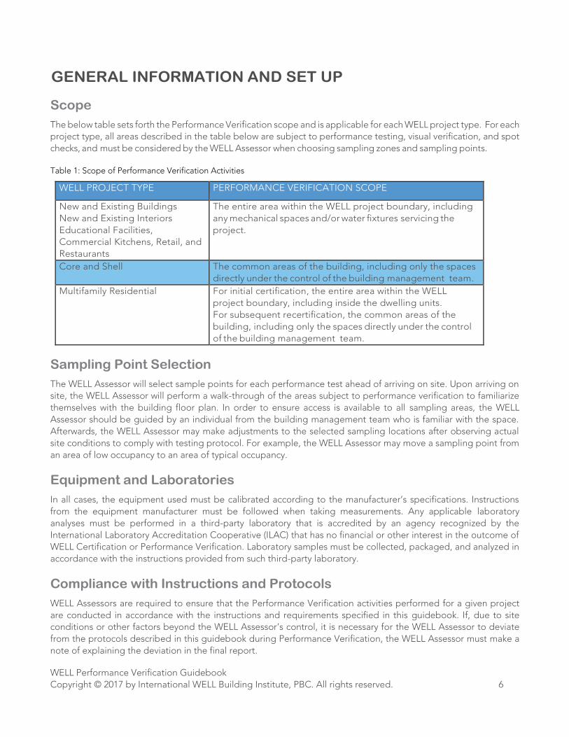
GENERAL INFORMATION AND SET UP
Scope
The below table sets forth the Performance Verification scope and is applicable for each WELL project type. For each
project type, all areas described in the table below are subject to performance testing, visual verification, and spot
checks, and must be considered by the WELL Assessor when choosing sampling zones and sampling points.
Table 1: Scope of Performance Verification Activities
WELL PROJECT TYPE PERFORMANCE VERIFICATION SCOPE
New and Existing Buildings
New and Existing Interiors
Educational Facilities,
Commercial Kitchens, Retail, and
Restaurants
The entire area within the WELL project boundary, including
any mechanical spaces and/or water fixtures servicing the
project.
Core and Shell The common areas of the building, including only the spaces
directly under the control of the building management team.
Multifamily Residential For initial certification, the entire area within the WELL
project boundary, including inside the dwelling units.
For subsequent recertification, the common areas of the
building, including only the spaces directly under the control
of the building management team.
Sampling Point Selection
The WELL Assessor will select sample points for each performance test ahead of arriving on site. Upon arriving on
site, the WELL Assessor will perform a walk-through of the areas subject to performance verification to familiarize
themselves with the building floor plan. In order to ensure access is available to all sampling areas, the WELL
Assessor should be guided by an individual from the building management team who is familiar with the space.
Afterwards, the WELL Assessor may make adjustments to the selected sampling locations after observing actual
site conditions to comply with testing protocol. For example, the WELL Assessor may move a sampling point from
an area of low occupancy to an area of typical occupancy.
Equipment and Laboratories
In all cases, the equipment used must be calibrated according to the manufacturer’s specifications. Instructions
from the equipment manufacturer must be followed when taking measurements. Any applicable laboratory
analyses must be performed in a third-party laboratory that is accredited by an agency recognized by the
International Laboratory Accreditation Cooperative (ILAC) that has no financial or other interest in the outcome of
WELL Certification or Performance Verification. Laboratory samples must be collected, packaged, and analyzed in
accordance with the instructions provided from such third-party laboratory.
Compliance with Instructions and Protocols
WELL Assessors are required to ensure that the Performance Verification activities performed for a given project
are conducted in accordance with the instructions and requirements specified in this guidebook. If, due to site
conditions or other factors beyond the WELL Assessor’s control, it is necessary for the WELL Assessor to deviate
from the protocols described in this guidebook during Performance Verification, the WELL Assessor must make a
note of explaining the deviation in the final report.
WELL Performance Verification Guidebook
Copyright © 2017 by International WELL Building Institute, PBC. All rights reserved. 7
PERFORMANCE TESTING PROTOCOL
The following protocol describes the performance testing requirements for each applicable parameter in the WELL
Building Standard – those marked as Performance Test or Spot Measurement in Appendix D of the standard. Parts
marked as Performance Test are validated solely through the on-site verification process, while those labeled Spot
Check are sampled on-site while also previously attested to by the project team during the document submission
process.
Performance testing protocol is outlined by Feature and Part. In cases where testing protocol is identical, Features
and Parts have been grouped.
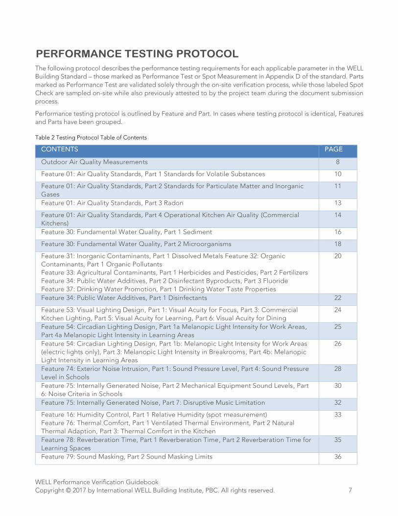
Table 2 Testing Protocol Table of Contents
CONTENTS PAGE
Outdoor Air Quality Measurements 8
Feature 01: Air Quality Standards, Part 1 Standards for Volatile Substances 10
Feature 01: Air Quality Standards, Part 2 Standards for Particulate Matter and Inorganic
Gases
11
Feature 01: Air Quality Standards, Part 3 Radon 13
Feature 01: Air Quality Standards, Part 4 Operational Kitchen Air Quality (Commercial
Kitchens)
14
Feature 30: Fundamental Water Quality, Part 1 Sediment 16
Feature 30: Fundamental Water Quality, Part 2 Microorganisms 18
Feature 31: Inorganic Contaminants, Part 1 Dissolved Metals Feature 32: Organic
Contaminants, Part 1 Organic Pollutants
Feature 33: Agricultural Contaminants, Part 1 Herbicides and Pesticides, Part 2 Fertilizers
Feature 34: Public Water Additives, Part 2 Disinfectant Byproducts, Part 3 Fluoride
Feature 37: Drinking Water Promotion, Part 1 Drinking Water Taste Properties
20
Feature 34: Public Water Additives, Part 1 Disinfectants 22
Feature 53: Visual Lighting Design, Part 1: Visual Acuity for Focus, Part 3: Commercial
Kitchen Lighting, Part 5: Visual Acuity for Learning, Part 6: Visual Acuity for Dining
24
Feature 54: Circadian Lighting Design, Part 1a Melanopic Light Intensity for Work Areas,
Part 4a Melanopic Light Intensity in Learning Areas
25
Feature 54: Circadian Lighting Design, Part 1b: Melanopic Light Intensity for Work Areas
(electric lights only), Part 3: Melanopic Light Intensity in Breakrooms, Part 4b: Melanopic
Light Intensity in Learning Areas
26
Feature 74: Exterior Noise Intrusion, Part 1: Sound Pressure Level, Part 4: Sound Pressure
Level in Schools
28
Feature 75: Internally Generated Noise, Part 2 Mechanical Equipment Sound Levels, Part
6: Noise Criteria in Schools
30
Feature 75: Internally Generated Noise, Part 7: Disruptive Music Limitation 32
Feature 16: Humidity Control, Part 1 Relative Humidity (spot measurement)
Feature 76: Thermal Comfort, Part 1 Ventilated Thermal Environment, Part 2 Natural
Thermal Adaption, Part 3: Thermal Comfort in the Kitchen
33
Feature 78: Reverberation Time, Part 1 Reverberation Time, Part 2 Reverberation Time for
Learning Spaces
35
Feature 79: Sound Masking, Part 2 Sound Masking Limits 36
WELL Performance Verification Guidebook
Copyright © 2017 by International WELL Building Institute, PBC. All rights reserved. 8
Outdoor Air Quality Measurements
In addition to indoor samples, the WELL Assessor must collect data on the outside air quality conditions.
Parameters Measured
• Carbon monoxide (CO)
• PM2.5
• PM10
• Ozone (O3)
Method of Measurement
• All parameters: direct reading instrument
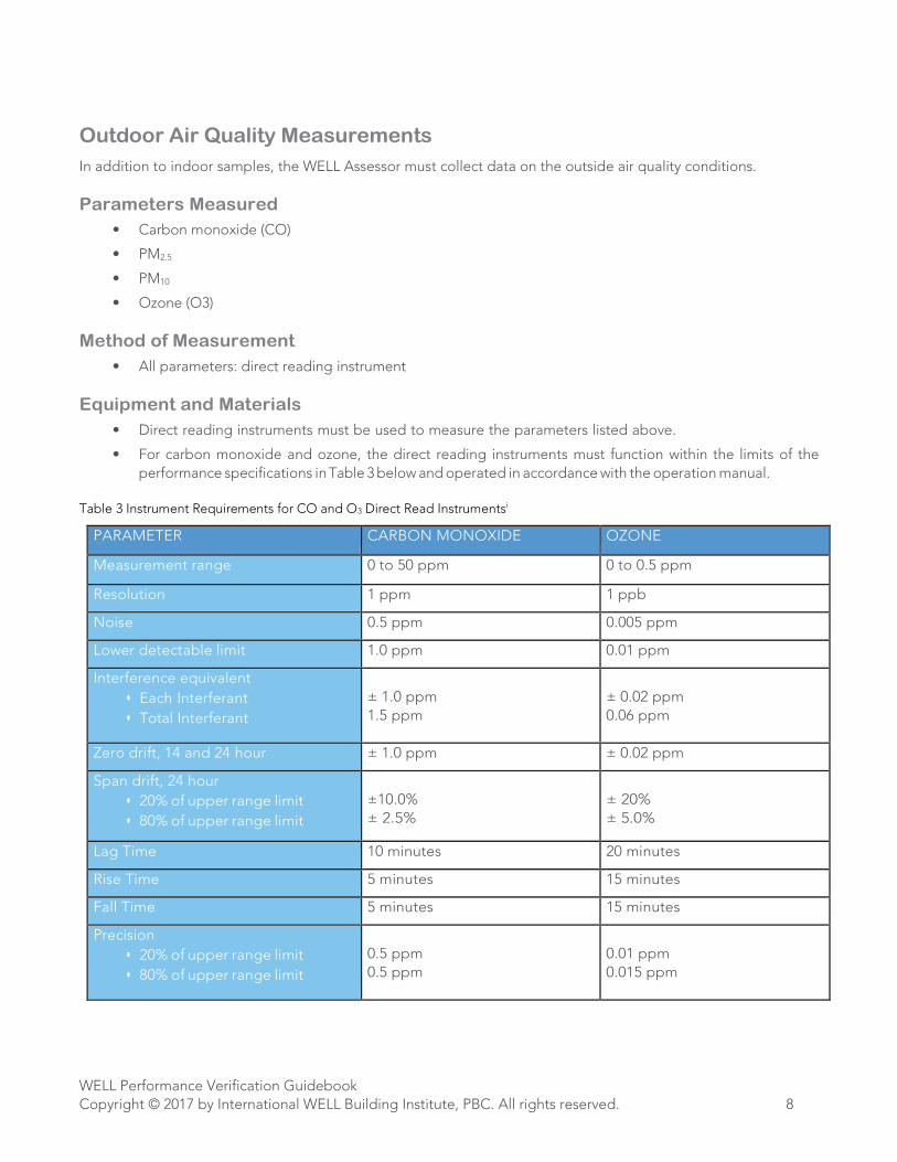
Equipment and Materials
• Direct reading instruments must be used to measure the parameters listed above.
• For carbon monoxide and ozone, the direct reading instruments must function within the limits of the
performance specifications in Table 3 below and operated in accordance with the operation manual.
Table 3 Instrument Requirements for CO and O3 Direct Read Instrumentsi
PARAMETER CARBON MONOXIDE OZONE
Measurement range 0 to 50 ppm 0 to 0.5 ppm
Resolution 1 ppm 1 ppb
Noise 0.5 ppm 0.005 ppm
Lower detectable limit 1.0 ppm 0.01 ppm
Interference equivalent
• Each Interferant
• Total Interferant
± 1.0 ppm
1.5 ppm
± 0.02 ppm
0.06 ppm
Zero drift, 14 and 24 hour ± 1.0 ppm ± 0.02 ppm
Span drift, 24 hour
• 20% of upper range limit
• 80% of upper range limit
±10.0%
± 2.5%
± 20%
± 5.0%
Lag Time 10 minutes 20 minutes
Rise Time 5 minutes 15 minutes
Fall Time 5 minutes 15 minutes
Precision
• 20% of upper range limit
• 80% of upper range limit
0.5 ppm
0.5 ppm
0.01 ppm
0.015 ppm
WELL Performance Verification Guidebook
Copyright © 2017 by International WELL Building Institute, PBC. All rights reserved. 9
For PM2.5
and PM10
, the sum of
• the lower end of the measurement ranges of the instrument and
• 3 times the on-screen resolution must be less than the WELL Building Standard threshold for the
parameter being measured.
Example 1:
WELL Building Standard threshold for PM2.5
: 15 µg/m3
Lower end of the measurement range of the instrument: 10 µg/m3 On-screen resolution on the device: 2 µg/m3
The sum of the lower end of the measurement range of the device and 3 times the on-screen resolution is 16. This
value exceeds the WELL Building Standard threshold for PM2.5
. Therefore, the instrument does not qualify for
measuring PM2.5
.
Example 2:
WELL Building Standard threshold for PM2.5
: 15 µg/m3
Lower end of the measurement range of the instrument: 10 µg/m3 On-screen resolution on the device: 1 µg/m3
The sum of the lower end of the measurement range of the device and 3 times the on-screen resolution is 13. This
value is below the WELL Building Standard threshold for PM2.5
. Therefore, the instrument qualifies for measuring
PM2.5
.
Sampling Points
• Measurements will be recorded at a representative outside air intake that supplies air to the project space.
• When access to an outside air intake serving the project space is not available, the measurements must be
recorded outside of the main entrance to the building containing the WELL project. Sampling points
outside the building entrance shall be within 25 feet of a major entrance and within the breathing zone (3
to 6 feet above the ground).
Duration of Measurement
• 15 minutes (5 minutes of acclimation time followed by 10 minutes of measurement time)
Additional WELL Methodology Requirements
• A total of three outdoor air measurements are required throughout the day:
o Morning (between 7 AM and 9 AM)
o Midday (between 11 AM and 3 PM)
o Evening (between 5 PM and 8 PM)
• At least three hours must separate each outdoor measurement.
• The WELL Assessor must also note any environmental conditions that could affect outdoor air quality
measurements (e.g., high traffic).
WELL Performance Verification Guidebook
Copyright © 2017 by International WELL Building Institute, PBC. All rights reserved. 10
Feature 01: Air Quality Standards, Part 1 Standards for Volatile
Substances
Parameters Measured
• Formaldehyde
• Total volatile organic compounds (TVOCs)
Method of Measurement
• Formaldehyde: chromatographic analysis of air collected onto a substrate (either diffusive or active collection)
in accordance with ISO 16000-3-2011, or formaldehyde samplers in accordance with ISO 16000-4-2011, or
methods in accordance with NIOSH 2016M, NIOSH 2017, NIOSH 3500, EPA TO-11, ASTM D5197 or EPA
Compendium Method IP-6.
• Total VOCs: chromatographic analysis of air collected onto a substrate (either diffusive or active collection)
in accordance with ISO 16000-6, EPA TO-1, TO-17, EPA Compendium Method IP-1, NIOSH 2549, EPA TO-15,
or OSHA Validation Guidelines for Air Sampling Methods Utilizing Chromatographic Analysis.
Equipment and Materials
• Laboratory materials and/or samplers must be prepared according to the referenced testing methodology
and meet the referenced testing methodology requirements.
• Air sampling pumps utilized in active collection measurements must be capable of meeting the air flow
rates prescribed by the referenced testing methodology, if applicable.
Sampling Points
• One sampling point in each major sampling zone (see Appendix A for details on major sampling zone
selection)
• Sampling points must be representative of typical occupied areas within the sampling zone
• Sampling points must be within the breathing zone (3 to 6 feet above the finished floor)
Duration of Measurement
• Active collection: Minimum of 2 continuous hours OR the duration of sampling volume prescribed by the
referenced testing methodology (120 min)
• Diffusive collection: duration of a typical workday (8 hours. / 480 min.) OR duration specified by sampling
kit manufacturer
Additional WELL Methodology Requirements
• Total VOCs: a minimum of one exposure field blank sample per day of sampling must be prepared and
analyzed.
• Formaldehyde: a minimum of one exposure field blank sample must be prepared and analyzed per day of
sampling.
• Testing should be done under regular project conditions. For naturally ventilated spaces, if the windows
are required to be opened to meet Feature 3 outside air requirements, then the windows should be open
during testing.

WELL Performance Verification Guidebook
Copyright © 2017 by International WELL Building Institute, PBC. All rights reserved. 11
Feature 01: Air Quality Standards, Part 2 Standards for Particulate
Matter and Inorganic Gases
Parameters Measured
• Carbon monoxide (CO)
• PM2.5
• PM10
• Ozone (O3)
Method of Measurement
• All parameters: direct reading instrument
Equipment and Materials
• Direct reading instruments must be used to measure the parameters listed above.
• For carbon monoxide and ozone, the direct reading instruments must function within the limits of the
performance specifications in the table below when operated in accordance with the operation manual.
Table 4 Requirements for CO and O3 Direct Reading Instrumentsii
PARAMETER CARBON MONOXIDE OZONE
Measurement range 0 to 50 ppm 0 to 0.5 ppm
Resolution 1 ppm 1 ppb
Noise 0.5 ppm 0.005 ppm
Lower detectable limit 1.0 ppm 0.01 ppm
Interference equivalent
• Each Interferant
• Total Interferant
± 1.0 ppm
1.5 ppm
± 0.02 ppm
0.06 ppm
Zero drift, 14 and 24 hour ± 1.0 ppm ± 0.02 ppm
Span drift, 24 hour
• 20% of upper range limit
• 80% of upper range limit
±10.0%
± 2.5%
± 20%
± 5.0%
Lag Time 10 minutes 20 minutes
Rise Time 5 minutes 15 minutes
Fall Time 5 minutes 15 minutes
Precision
• 20% of upper range limit
• 80% of upper range limit
0.5 ppm
0.5 ppm
0.01 ppm
0.015 ppm
WELL Performance Verification Guidebook
Copyright © 2017 by International WELL Building Institute, PBC. All rights reserved. 12
• For PM2.5
and PM10
, the sum of
a) the lower end of the measurement ranges of the instrument and
b) 3 times the on-screen resolution
must be less than the WELL Building Standard threshold for the parameter being measured.
Example 1:
WELL Building Standard threshold for PM2.5: 15 µg/m3
Lower end of the measurement range of the instrument: 10 µg/m3 On-screen resolution on the device: 2 µg/m3
The sum of the lower end of the measurement range of the device and 3 times the on-screen resolution is 16. This
value exceeds the WELL Building Standard threshold for PM2.5. Therefore, the instrument does not qualify for
measuring PM2.5.
Example 2:
WELL Building Standard threshold for PM2.5: 15 µg/m3
Lower end of the measurement range of the instrument: 10 µg/m3 On-screen resolution on the device: 1 µg/m3
The sum of the lower end of the measurement range of the device and 3 times the on-screen resolution is 13. This
value is below the WELL Building Standard threshold for PM2.5
. Therefore, the instrument qualifies for measuring
PM2.5
.
Sampling Points
• At least one sampling point in each major AND each minor sampling zone (refer to Appendix A for details on
major and minor sampling zone selection)
• Sampling points must be representative of typical occupied areas within the sampling zone
• Sampling points must be within the breathing zone (3 to 6 feet above the finished floor)
Duration of Measurement
• Major sampling points: 2 hours total (10 minutes of acclimation time followed by 1 hour and 50 minutes of
measurement time), with measurements recorded at least once every 5 minutes
• Minor sampling points: 30 minutes total (10 minutes of acclimation time followed by 20 minutes of
measurement time), with measurements recorded at least once every 5 minutes
Additional WELL Methodology Requirements
• The WELL Assessor should note whether the HVAC system (or any air treatment systems) turn on or off
during the data collection period
Reporting Notes
• The 50th percentile value collected during the measurement time at each sampling point is reported and
used to determine compliance with the WELL Building Standard requirements
WELL Performance Verification Guidebook
Copyright © 2017 by International WELL Building Institute, PBC. All rights reserved. 13
Feature 01: Air Quality Standards, Part 3 Radon
Parameters Measured
• Radon
Method of Measurement
• Passive Radon sampler
Equipment and Materials
• For charcoal sample kits, short-term radon test kits are permitted. Professional Note: Long-term test kits
are preferred if the building can be accessed outside of Performance Verification for placement or retrieval.
Sampling Points
• Measurements are only required in the lowest occupied level of the project site. If the project does not
contain the ground floor of the building (defined as the first aboveground floor), or any below-grade
floors, radon testing is not required.
• One radon sampler is required for every 2,000 square feet of floor plate on the lowest occupied level
• Radon samplers must be located:
• 0.91 m (3 ft.) from windows and exterior doors
• 20.3 cm 12 inches from exterior walls
• 50.8 cm (20 inches) above the finished floor
Duration of Measurement
• Minimum of 48 hours, or the entire length of the performance verification, whichever is longer.
WELL Performance Verification Guidebook
Copyright © 2017 by International WELL Building Institute, PBC. All rights reserved. 14
Feature 01: Air Quality Standards, Part 4 Operational Kitchen Air Quality
(Commercial Kitchens)
Parameters Measured
• Carbon monoxide (CO)
• PM2.5
• NO2
• Formaldehyde
Method of Measurement
• CO and PM2.5: direct reading instrument
• NO2: ASTM D1607
• Formaldehyde: chromatographic analysis of air collected onto a substrate (either diffusive or active
collection) in accordance with ISO 16000-3-2011, or formaldehyde samplers in accordance with ISO 16000-
4-2011, or methods in accordance with NIOSH 2016M, NIOSH 2017, NIOSH 3500, EPA TO-11, ASTM D5197
or EPA Compendium Method IP-6.
Equipment and Materials
• Direct reading instruments for must be used to measure CO and PM2.5.
• For carbon monoxide, the direct reading instruments must function within the limits of the performance-
specific Sampling Points
• Tests in Commercial Kitchens are independent of major and minor sampling zone designation. For
example, a small Restaurant with a Commercial Kitchen would include two major zones outside the kitchen
area and one test within the kitchen using this Feature 03, Part 4 methodology.
• Sampling points must be representative of typical occupied areas within the sampling zone
• Sampling points must be within the breathing zone (3 to 6 feet above the finished floor)
Duration of Measurement
• Active collection: Minimum of 2 continuous hours OR the maximum duration of sampling volume
prescribed by the referenced testing methodology (120 min)
• Diffusive collection: duration of a typical workday (8 hours/480 min) OR duration specified by sampling kit
manufacturer
Additional WELL Methodology Requirements
• The WELL Assessor should note whether the HVAC system (or any air treatment systems) turn on or off
during the data collection period.
• Formaldehyde: a minimum of one exposure field blank sample must be prepared and analyzed per day of
sampling.
• Testing should be done under regular project conditions. For naturally ventilated spaces, if the windows
are required to be opened to meet Feature 3 outside air requirements, then the windows should be open
during testing.
WELL Performance Verification Guidebook
Copyright © 2017 by International WELL Building Institute, PBC. All rights reserved. 15
Reporting Notes
• The 50th percentile value collected during the measurement time at each sampling point is reported and
used to determine compliance with the WELL Building Standard requirements.
WELL Performance Verification Guidebook
Copyright © 2017 by International WELL Building Institute, PBC. All rights reserved. 16
Feature 30: Fundamental Water Quality, Part 1 Sediment
Parameters Measured
• Turbidity
Method of Measurement
• Water samples are evaluated with a turbidimeter
Equipment and Materials
• The turbidimeter must function within the limits of the performance specifications in the below table when
operated in accordance with the operation manual.
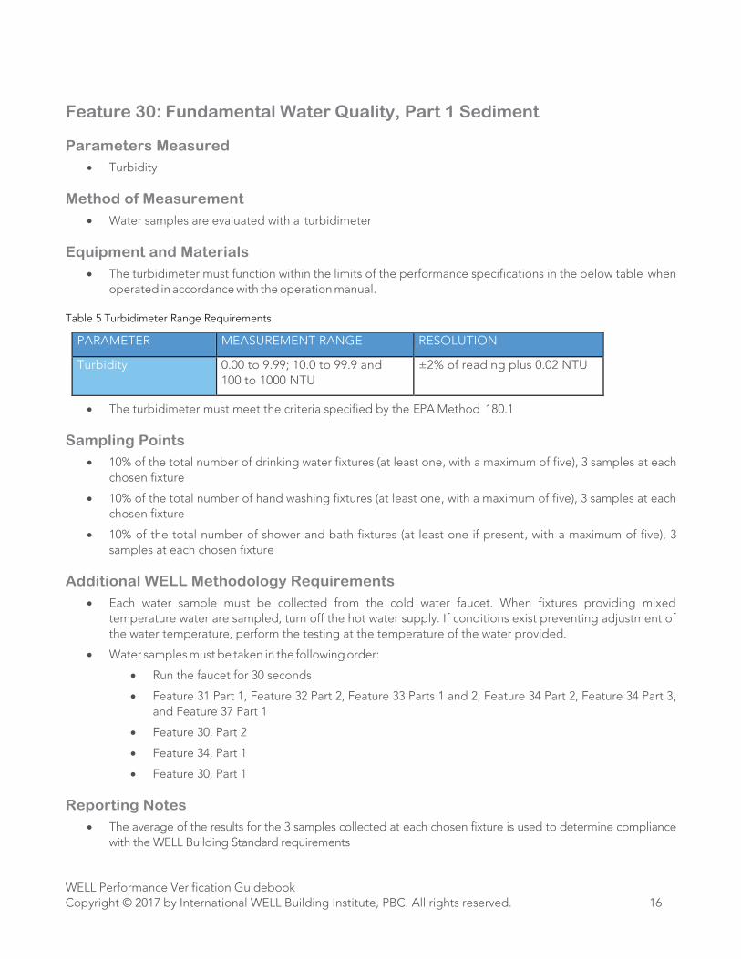
Table 5 Turbidimeter Range Requirements
PARAMETER MEASUREMENT RANGE RESOLUTION
Turbidity 0.00 to 9.99; 10.0 to 99.9 and
100 to 1000 NTU
±2% of reading plus 0.02 NTU
• The turbidimeter must meet the criteria specified by the EPA Method 180.1
Sampling Points
• 10% of the total number of drinking water fixtures (at least one, with a maximum of five), 3 samples at each
chosen fixture
• 10% of the total number of hand washing fixtures (at least one, with a maximum of five), 3 samples at each
chosen fixture
• 10% of the total number of shower and bath fixtures (at least one if present, with a maximum of five), 3
samples at each chosen fixture
Additional WELL Methodology Requirements
• Each water sample must be collected from the cold water faucet. When fixtures providing mixed
temperature water are sampled, turn off the hot water supply. If conditions exist preventing adjustment of
the water temperature, perform the testing at the temperature of the water provided.
• Water samples must be taken in the following order:
• Run the faucet for 30 seconds
• Feature 31 Part 1, Feature 32 Part 2, Feature 33 Parts 1 and 2, Feature 34 Part 2, Feature 34 Part 3,
and Feature 37 Part 1
• Feature 30, Part 2
• Feature 34, Part 1
• Feature 30, Part 1
Reporting Notes
• The average of the results for the 3 samples collected at each chosen fixture is used to determine compliance
with the WELL Building Standard requirements
WELL Performance Verification Guidebook
Copyright © 2017 by International WELL Building Institute, PBC. All rights reserved. 17
• When conditions exist preventing adjustment of the water temperature, perform the testing at the temperature
of the water provided and accompany the recorded testing data with an explanatory note indicating that the
temperature could not be adjusted and whether the water temperature was mild, warm, or hot.
WELL Performance Verification Guidebook
Copyright © 2017 by International WELL Building Institute, PBC. All rights reserved. 18
Feature 30: Fundamental Water Quality, Part 2 Microorganisms
Parameters Measured
• Total coliforms (including E. coli)
Method of Measurement
• Water samples are evaluated by a third party laboratory in accordance with EPA 1604, ISO 9308-1:2001.
Equipment and Materials
• Appropriate sampling vials must be obtained from a third party laboratory prior to Performance
Verification.
Sampling Points
• 10% of the total number of drinking water fixtures (at least one, with a maximum of five), 1 sample at each
chosen fixture
• NOTE: If there is no designated drinking water fixture, then water from the kitchen faucet or next most likely
source is used in its place.
• 10% of the total number of hand washing fixtures (at least one, with a maximum of five), 1 sample at each
chosen fixture
• 10% of the total number of shower and bath fixtures (at least one if present, with a maximum of five), 1
sample at each chosen fixture
• 5% of the total number of water fixtures used for cooking purposes for Commercial Kitchens, 1 sample at
each chosen fixture
Additional WELL Methodology Requirements
• Each water sample must be collected from the cold water faucet. When fixtures providing mixed
temperature water are sampled, turn off the hot water supply. If conditions exist preventing adjustment of
the water temperature, perform the testing at the temperature of the water provided.
• Water samples must be taken in the following order:
o Run the faucet for 30 seconds
o Feature 31 Part 1, Feature 32 Part 2, Feature 33 Parts 1 and 2, Feature 34 Part 2, Feature 34 Part 3, and
Feature 37 Part 1
o Feature 30, Part 2
o Feature 34, Part 1
o Feature 30, Part 1
• Follow all laboratory procedures for collecting and packaging the sample.
• Package and ship sample to third party testing laboratory per the laboratory’s instructions. Total coliforms
sampling analysis is time sensitive and the samples should be shipped to the laboratory overnight the same
day that they are collected, or couriered or driven to the laboratory on the same day that they are collected.
Sample design must take into account the fact that samples are not permitted to be shipped on a Friday,
due to the risk of delays in custody transfer and degradation of samples in storage.
WELL Performance Verification Guidebook
Copyright © 2017 by International WELL Building Institute, PBC. All rights reserved. 19
Reporting Notes
• When conditions exist preventing adjustment of the water temperature, perform the testing at the
temperature of the water provided but accompany the recorded testing data with an explanatory note
indicating that the temperature could not be adjusted and whether the water temperature was mild, warm,
or hot.
WELL Performance Verification Guidebook
Copyright © 2017 by International WELL Building Institute, PBC. All rights reserved. 20
Feature 31: Inorganic Contaminants, Part 1 Dissolved Metals
Feature 32: Organic Contaminants, Part 1 Organic Pollutants
Feature 33: Agricultural Contaminants, Part 1 Herbicides and Pesticides
Feature 33: Agricultural Contaminants, Part 2 Fertilizers
Feature 34: Public Water Additives, Part 2 Disinfectant Byproducts
Feature 34: Public Water Additives, Part 3 Fluoride
Feature 37: Drinking Water Promotion, Part 1 Drinking Water Taste
Properties
Parameters Measured
• Feature 31: Lead, Arsenic, Antimony, Mercury, Nickel, Copper
• Feature 32, Part 1: Styrene, Benzene, Ethyl benzene, Polychlorinated biphenyls, Vinyl chloride, Toluene,
Xylenes (total: m, p, and o), Tetrachloroethylene
• Feature 33, Part 1: Atrazine, Simazine, Glyphosate, 2,4-dichlorophenoxyacetic acid
• Feature 33, Part 2: Nitrate (as nitrogen)
• Feature 34, Part 2: Total trihalomethanes, Total halo acetic acids
• Feature 34, Part 3: Fluoride
• Feature 37: Aluminum, Chloride, Manganese, Sodium, Sulfate, Iron, Zinc, Total dissolved solids
Method of Measurement
• Water samples are evaluated by a third party laboratory.
Equipment and Materials
• Appropriate sampling vials must be obtained from a third party laboratory prior to Performance
Verification.
Sampling Points
• 10% of the total number of drinking water fixtures (at least one, with a maximum of five), one sample at
each chosen fixture.
• 5% of the total number of water fixtures used for cooking purposes for Commercial Kitchens, one sample
at each chosen fixture.
Additional WELL Methodology Requirements
• Each water sample must be collected from the cold water faucet. When fixtures providing mixed
temperature water are sampled, turn off the hot water supply. If conditions exist preventing adjustment of
the water temperature, perform the testing at the temperature of the water provided.
• Water samples must be taken in the following order:
o Run the faucet for 30 seconds
o Feature 31 Part 1, Feature 32 Part 2, Feature 33 Parts 1 and 2, Feature 34 Part 2, Feature 34 Part 3, and
Feature 37 Part 1
o Feature 30, Part 2
WELL Performance Verification Guidebook
Copyright © 2017 by International WELL Building Institute, PBC. All rights reserved. 21
o Feature 34, Part 1
o Feature 30, Part 1
• Follow all laboratory procedures for collecting and packaging the sample.
• Package and ship sample to third party testing laboratory per the laboratory’s instructions.
Reporting Notes
• When conditions exist preventing adjustment of the water temperature, perform the testing at the
temperature of the water provided but accompany the recorded testing data with an explanatory note
indicating that the temperature could not be adjusted and whether the water temperature was mild, warm,
or hot.
WELL Performance Verification Guidebook
Copyright © 2017 by International WELL Building Institute, PBC. All rights reserved. 22
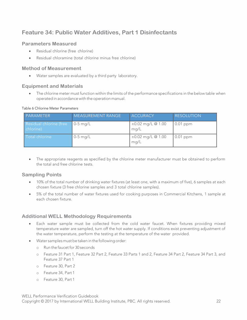
Feature 34: Public Water Additives, Part 1 Disinfectants
Parameters Measured
• Residual chlorine (free chlorine)
• Residual chloramine (total chlorine minus free chlorine)
Method of Measurement
• Water samples are evaluated by a third party laboratory.
Equipment and Materials
• The chlorine meter must function within the limits of the performance specifications in the below table when
operated in accordance with the operation manual.
Table 6 Chlorine Meter Parameters
PARAMETER MEASUREMENT RANGE ACCURACY RESOLUTION
Residual chlorine (free
chlorine)
0-5 mg/L ±0.02 mg/L @ 1.00
mg/L
0.01 ppm
Total chlorine 0-5 mg/L ±0.02 mg/L @ 1.00
mg/L
0.01 ppm
• The appropriate reagents as specified by the chlorine meter manufacturer must be obtained to perform
the total and free chlorine tests.
Sampling Points
• 10% of the total number of drinking water fixtures (at least one, with a maximum of five), 6 samples at each
chosen fixture (3 free chlorine samples and 3 total chlorine samples).
• 5% of the total number of water fixtures used for cooking purposes in Commercial Kitchens, 1 sample at
each chosen fixture.
Additional WELL Methodology Requirements
• Each water sample must be collected from the cold water faucet. When fixtures providing mixed
temperature water are sampled, turn off the hot water supply. If conditions exist preventing adjustment of
the water temperature, perform the testing at the temperature of the water provided.
• Water samples must be taken in the following order:
o Run the faucet for 30 seconds
o Feature 31 Part 1, Feature 32 Part 2, Feature 33 Parts 1 and 2, Feature 34 Part 2, Feature 34 Part 3, and
Feature 37 Part 1
o Feature 30, Part 2
o Feature 34, Part 1
o Feature 30, Part 1
WELL Performance Verification Guidebook
Copyright © 2017 by International WELL Building Institute, PBC. All rights reserved. 23
Reporting Notes
• To calculate residual chloramines, subtract the free chlorine value from the total chlorine value.
• The average of the results for the 3 samples collected at each chosen fixture is used to determine
compliance with the WELL Building Standard requirements.
• When conditions exist preventing adjustment of the water temperature, perform the testing at the
temperature of the water provided but accompany the recorded testing data with an explanatory note
indicating that the temperature could not be adjusted and whether the water temperature was mild, warm,
or hot.
WELL Performance Verification Guidebook
Copyright © 2017 by International WELL Building Institute, PBC. All rights reserved. 24
Feature 53: Visual Lighting Design Part 1: Visual Acuity for Focus
Part 3: Commercial Kitchen Lighting
Part 5: Visual Acuity for Learning
Part 6: Visual Acuity for Dining
Parameters Measured
• Ambient lighting illuminance
Measured Method of Measurement
• Lux meter
Equipment and Materials
• The lux meter must function within the limits of the performance specifications in the below table when
operated in accordance with the operation manual:
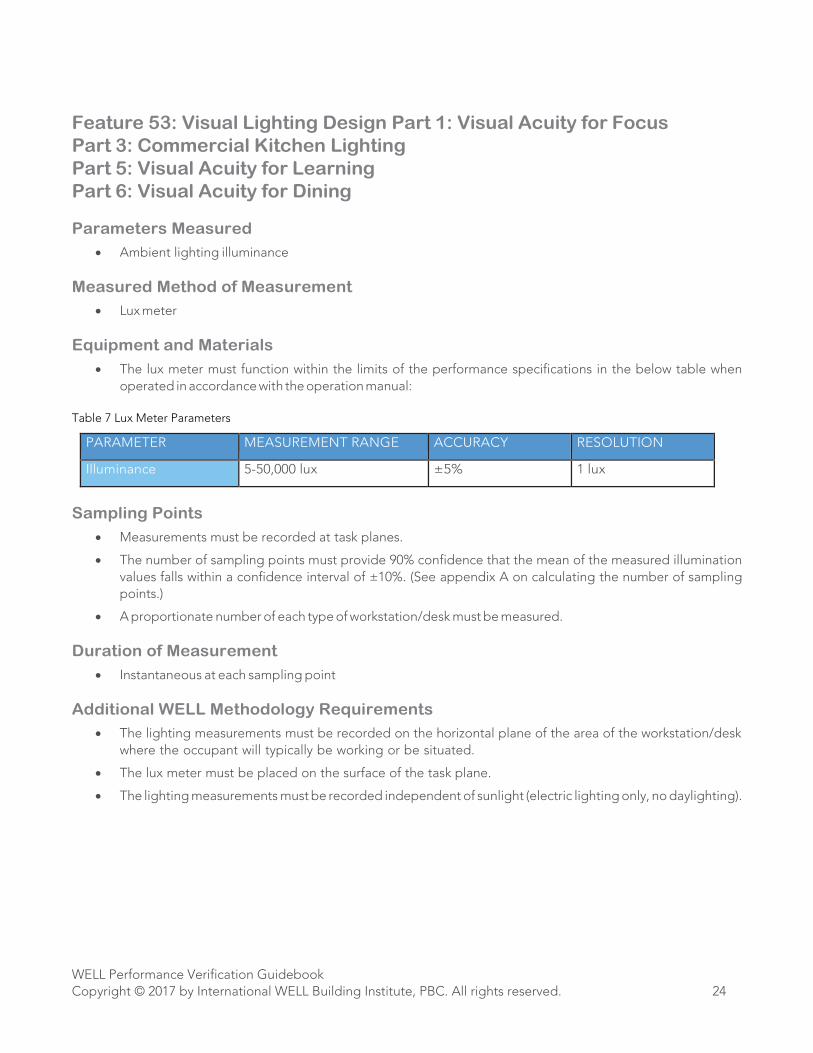
Table 7 Lux Meter Parameters
PARAMETER MEASUREMENT RANGE ACCURACY RESOLUTION
Illuminance 5-50,000 lux ±5% 1 lux
Sampling Points
• Measurements must be recorded at task planes.
• The number of sampling points must provide 90% confidence that the mean of the measured illumination
values falls within a confidence interval of ±10%. (See appendix A on calculating the number of sampling
points.)
• A proportionate number of each type of workstation/desk must be measured.
Duration of Measurement
• Instantaneous at each sampling point
Additional WELL Methodology Requirements
• The lighting measurements must be recorded on the horizontal plane of the area of the workstation/desk
where the occupant will typically be working or be situated.
• The lux meter must be placed on the surface of the task plane.
• The lighting measurements must be recorded independent of sunlight (electric lighting only, no daylighting).
WELL Performance Verification Guidebook
Copyright © 2017 by International WELL Building Institute, PBC. All rights reserved. 25
Feature 54: Circadian Lighting Design
Part 1a: Melanopic Light Intensity for Work Areas
Part 4a: Melanopic Light Intensity in Learning Areas
Parameters Measured
• Equivalent melanopic lux
Measured Method of Measurement
• Optical spectrometer
Equipment and Materials
• The optical spectrometer must function within the limits of the performance specifications in the below table
when operated in accordance with the operation manual.
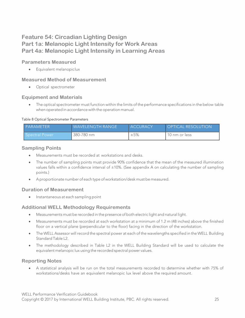
Table 8 Optical Spectrometer Parameters
PARAMETER WAVELENGTH RANGE ACCURACY OPTICAL RESOLUTION
Spectral Power 380-780 nm ±5% 10 nm or less
Sampling Points
• Measurements must be recorded at workstations and desks.
• The number of sampling points must provide 90% confidence that the mean of the measured illumination
values falls within a confidence interval of ±10%. (See appendix A on calculating the number of sampling
points.)
• A proportionate number of each type of workstation/desk must be measured.
Duration of Measurement
• Instantaneous at each sampling point
Additional WELL Methodology Requirements
• Measurements must be recorded in the presence of both electric light and natural light.
• Measurements must be recorded at each workstation at a minimum of 1.2 m (48 inches) above the finished
floor on a vertical plane (perpendicular to the floor) facing in the direction of the workstation.
• The WELL Assessor will record the spectral power at each of the wavelengths specified in the WELL Building
Standard Table L2.
• The methodology described in Table L2 in the WELL Building Standard will be used to calculate the
equivalent melanopic lux using the recorded spectral power values.
Reporting Notes
• A statistical analysis will be run on the total measurements recorded to determine whether with 75% of
workstations/desks have an equivalent melanopic lux level above the required amount.
WELL Performance Verification Guidebook
Copyright © 2017 by International WELL Building Institute, PBC. All rights reserved. 26
Part 1b: Melanopic Light Intensity for Work Areas (electric lights only)
Part 3: Melanopic Light Intensity in Breakrooms
Part 4b: Melanopic Light Intensity in Learning Areas
Parameters Measured
• Equivalent melanopic lux
Measured Method of Measurement
• Optical spectrometer
Equipment and Materials
• The optical spectrometer must function within the limits of the performance specifications in the below table
when operated in accordance with the operation manual.
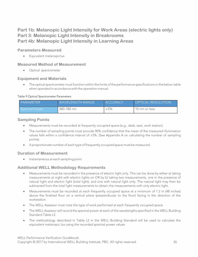
Table 9 Optical Spectrometer Parameters
PARAMETER WAVELENGTH RANGE ACCURACY OPTICAL RESOLUTION
Spectral Power 380-780 nm ±5% 10 nm or less
Sampling Points
• Measurements must be recorded at frequently occupied space (e.g., desk, seat, work station).
• The number of sampling points must provide 90% confidence that the mean of the measured illumination
values falls within a confidence interval of ±5%. (See Appendix A on calculating the number of sampling
points).
• A proportionate number of each type of frequently occupied space must be measured.
Duration of Measurement
• Instantaneous at each sampling point
Additional WELL Methodology Requirements
• Measurements must be recorded in the presence of electric light only. This can be done by either a) taking
measurements at night with electric lights on OR by b) taking two measurements, one in the presence of
natural light and electric light (total light), and one with natural light only. The natural light may then be
subtracted from the total light measurements to obtain the measurements with only electric light.
• Measurements must be recorded at each frequently occupied space at a minimum of 1.2 m (48 inches)
above the finished floor on a vertical plane (perpendicular to the floor) facing in the direction of the
workstation.
• The WELL Assessor must note the type of work performed at each frequently occupied space.
• The WELL Assessor will record the spectral power at each of the wavelengths specified in the WELL Building
Standard Table L2.
• The methodology described in Table L2 in the WELL Building Standard will be used to calculate the
equivalent melanopic lux using the recorded spectral power values
WELL Performance Verification Guidebook
Copyright © 2017 by International WELL Building Institute, PBC. All rights reserved. 27
Reporting Notes
• The calculated equivalent melanopic lux values for each sampling point will be compared against the
Vertical (Ev) targets for the 25-65 category in Table B1 of IES-ANSI RP-1-12 to determine compliance.
WELL Performance Verification Guidebook
Copyright © 2017 by International WELL Building Institute, PBC. All rights reserved. 28
Feature 74: Exterior Noise Intrusion
Part 1: Sound Pressure Level
Part 4: Sound Pressure Level in Schools
Parameters Measured
• Time-averaged, A-weighted, sound pressure level from outside noise intrusion (dBA)
Measured Method of Measurement
• Sound level meter
Equipment and Materials
• The sound level meter must function within the limits of the performance specifications in the below table
when operated in accordance with the operation manual.
Table 10 Sound Level Meter Parameters
PARAMETER BANDWIDTH ACCURACY RESOLUTION
Sound Level 20 Hz to 20 kHz ±0.5% at 1 kHz 0.1 dB
• The sound level meter must be capable of measuring the sound pressure level at each of the following
distinct octave band frequencies: 63 Hz, 125 Hz, 250 Hz, 500 Hz, 1 kHz, 2 kHz, 4 kHz, 8 kHz
Sampling Points
• Measurements are recorded in 10% of the total number of each regularly occupied room type in the project
(at least one of each room type).
• The number of sampling points per each chosen room is dependent on the total square footage of that room
(see table below). One measurement is recorded per sampling point.
Table 11 Number of Sampling Points Required Based on Square Footage
TOTAL ROOM SQUARE FOOTAGE NUMBER OF SAMPLING POINTS
<1,000 1
≥1,000 and < 5,000 2
≥5,000 and <10,000 3
≥10,000 and <15,000 4
≥15,000 and <20,000 5
≥20,000 6
Duration of Measurement
• 30 seconds at each sampling point
WELL Performance Verification Guidebook
Copyright © 2017 by International WELL Building Institute, PBC. All rights reserved. 29
Additional WELL Methodology Requirements
• The measurements must be performed when the space is unoccupied (e.g., prior to opening, lunch hour, or
after hours.)
• Avoid transient sounds (people talking, door closing, etc.) during the measurement periods.
• The HVAC system must be off during the measurement periods.
• Sound masking systems (if present) must be off for the duration of the measurement period.
• The sample points must be located at the location where an occupant would typically be situated within the
space.
• As much as possible, the sample points must be located 1 m (39 inches) from the window wall while still
located where an occupant would typically be situated.
• As much as possible, the sample points should be located farthest from sources of mechanical noise
including HVAC system ducts and elevators while still located where an occupant would typically be
situated.
• The sample points must be located at least 1.2 m (48 inches) above the finished floor.
• The distance between any two points of measurement must be at least 3 m (118 inches).
• If the windows are normally closed, the sound level measurements must occur with the windows closed. If the
windows are normally open, the sound level measurements must occur with the windows open.
Reporting Notes
• The time-averaged, A-weighted, sound pressure level recorded during the measurement period will be used
to determine compliance with the WELL Building Standard threshold.
WELL Performance Verification Guidebook
Copyright © 2017 by International WELL Building Institute, PBC. All rights reserved. 30
Feature 75: Internally Generated Noise
Part 2: Mechanical Equipment Noise
Part 6: Noise Criteria in Schools
Parameters Measured
• Noise criterion
Measured Method of Measurement
• Sound level meter
Equipment and Materials
• The sound level meter must function within the limits of the performance specifications in the below table
when operated in accordance with the operation manual.
Table 12 Sound Level Meter Parameters
PARAMETER BANDWIDTH ACCURACY RESOLUTION
Sound Level 20 Hz to 20 kHz ±0.5% at 1 kHz 0.1 dB
• The sound level meter must be capable of measuring the sound pressure level at each of the following
distinct octave band frequencies: 63 Hz, 125 Hz, 250 Hz, 500 Hz, 1 kHz, 2 kHz, 4 kHz, 8 kHz
Sampling Points
• 10% of the total number of each type of space specifically described in the WELL Building Standard,
Feature 75 Part 1 and Part 6, that are present in the project (e.g., conference rooms, open workspaces, and
classrooms) with at least one of each room type
Duration of Measurement
• 30 seconds at each sampling point
Additional WELL Methodology Requirements
• The measurements must be performed when the space is unoccupied (e.g., prior to opening, lunch hour,
or after hours)
• Avoid transient sounds (people talking, door closing, etc.) during the measurement.
• The HVAC system must be on during the measurement periods.
• Sound masking systems (if present) must be off during the measurement period.
• The sampling points must be located where an occupant would typically be situated within the space.
• As much as possible, sampling points should be located near sources of mechanical noise including HVAC
system ducts and elevators.
• As much as possible, sampling points should be located away from walls containing windows. The sampling
points must be located a minimum of 1.2 m (48 inches) above the finished floor.
• The distance between any two points of measurement must be at least 3 m (118 inches).
• Windows and doors in the sampling zone must be closed.
WELL Performance Verification Guidebook
Copyright © 2017 by International WELL Building Institute, PBC. All rights reserved. 31
• If the conditions specified above are violated during the measurement, the measurement must be halted,
data discarded, and restarted.
Reporting Notes
• The time-averaged sound pressure level measured at each of the following octave band frequencies is
plotted against noise criteria curves to determine the noise criterion: 63 Hz, 125 Hz, 250 Hz, 500 Hz, 1 kHz,
2 kHz, 4 kHz, and 8 k Hz.
• Note any existing intruding sounds that may interfere with an accurate measurement of noise criterion (e.g.,
traffic noise intrusion).

WELL Performance Verification Guidebook
Copyright © 2017 by International WELL Building Institute, PBC. All rights reserved. 32
Feature 75: Internally Generated Noise
Part 7: Disruptive Music Limitation
Parameters Measured
• Sound pressure level (dBA)
Measured Method of Measurement
• Sound level meter
Equipment and Materials
• The sound level meter must function within the limits of the performance specifications in the below table
when operated in accordance with the operation manual.
Table 13 Sound Level Meter Parameters
PARAMETER BANDWIDTH ACCURACY RESOLUTION
Sound Level 20 Hz to 20 kHz ±0.5% at 1 kHz 0.1 dB
• The sound level meter must be capable of measuring the sound pressure level at each of the following
distinct octave band frequencies: 63 Hz, 125 Hz, 250 Hz, 500 Hz, 1 kHz, 2 kHz, 4 kHz, 8 kHz
Sampling Points
• At least two (maximum of 4) and measured at a distance of 15 ft [4.5 m] outside of the entrance to the
space.
Duration of Measurement
• 30 seconds at each sampling point
Additional WELL Methodology Requirements
• The measurements must be performed when the space is unoccupied (e.g., prior to opening, lunch hour,
or after hours)
• Music must be off for one ambient measurement and music must be on for at least one measurement.
• Avoid transient sounds (people talking, traffic noise, etc.) during the measurement.
• The sampling points must be located where an occupant would typically be situated within the space.
• As much as possible, sampling points should be located away from walls and other building structures. The
sampling points must be located a minimum of 1.2 m (48 inches) above the ground.
• If the conditions specified above are violated during the measurement, the measurement must be halted,
data discarded, and restarted.
Reporting Notes
• The time-averaged sound pressure level measured at each of the following octave band frequencies is
plotted against measurements with and without music on: 63 Hz, 125 Hz, 250 Hz, 500 Hz, 1 kHz, 2 kHz, 4
kHz, and 8 kHz.
• Note any existing intruding sounds that may interfere with an accurate measurement of noise criterion (e.g.,
traffic noise).
WELL Performance Verification Guidebook
Copyright © 2017 by International WELL Building Institute, PBC. All rights reserved. 33
Feature 76: Thermal Comfort
Part 1: Ventilated Thermal Environment
Part 2: Natural Thermal Adaptation
Part 3: Thermal Comfort in the Kitchen
Parameters Measured
• Operative temperature
• Relative humidity
Measured Method of Measurement
• Direct reading instrument
Equipment and Materials
• The direct reading instrument must function within the limits of the performance specifications in the below
table when operated in accordance with the operation manual.
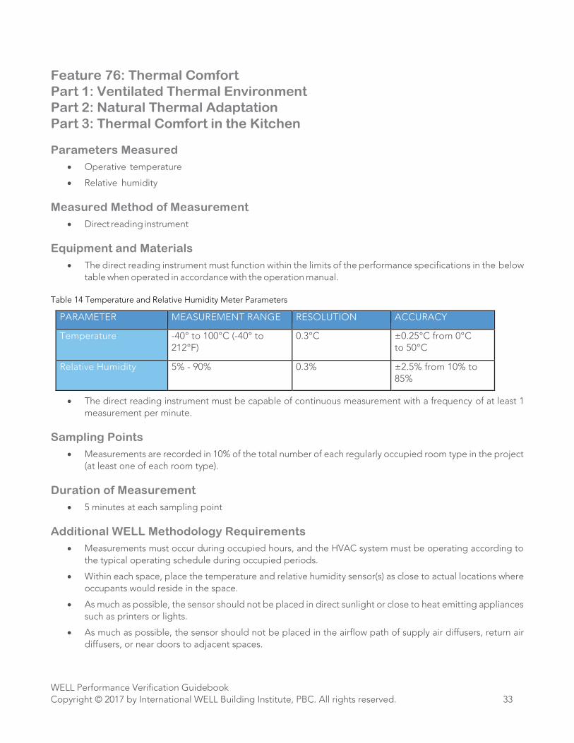
Table 14 Temperature and Relative Humidity Meter Parameters
PARAMETER MEASUREMENT RANGE RESOLUTION ACCURACY
Temperature -40° to 100°C (-40° to
212°F)
0.3°C ±0.25°C from 0°C
to 50°C
Relative Humidity 5% - 90% 0.3% ±2.5% from 10% to
85%
• The direct reading instrument must be capable of continuous measurement with a frequency of at least 1
measurement per minute.
Sampling Points
• Measurements are recorded in 10% of the total number of each regularly occupied room type in the project
(at least one of each room type).
Duration of Measurement
• 5 minutes at each sampling point
Additional WELL Methodology Requirements
• Measurements must occur during occupied hours, and the HVAC system must be operating according to
the typical operating schedule during occupied periods.
• Within each space, place the temperature and relative humidity sensor(s) as close to actual locations where
occupants would reside in the space.
• As much as possible, the sensor should not be placed in direct sunlight or close to heat emitting appliances
such as printers or lights.
• As much as possible, the sensor should not be placed in the airflow path of supply air diffusers, return air
diffusers, or near doors to adjacent spaces.
WELL Performance Verification Guidebook
Copyright © 2017 by International WELL Building Institute, PBC. All rights reserved. 34
• Individual comfort devices (such as space heaters or fans) must not be in operation in the immediate vicinity
of the sampling point. The temperature sensor must be placed between 0.6 m (24 inches) and 1.1 m (43
inches) above the finished floor.
• Testing will only occur in common spaces within 1 m [3.2 ft] of the exterior wall.
• The temperature sensor must be placed at least 1 m (39 inches) from walls, windows, and partitions.
• The distance between any two points of measurement must be at least 7.62 m [25 ft].
• If thermal comfort testing is interrupted during the sampling period, either by sensor disruption, irregular
gaps in normal occupancy, or modification to the HVAC operation, the measurements will be repeated the
following day provided conditions have normalized.
Reporting Notes
• The average space temperature or relative humidity collected at each measurement point will be used to
determine whether that sampling location complies with the requirements.
WELL Performance Verification Guidebook
Copyright © 2017 by International WELL Building Institute, PBC. All rights reserved. 35
Feature 78: Reverberation Time
Part 1: Reverberation Time
Part 2: Reverberation Time for Learning Spaces
Parameters Measured
• Reverberation time (RT 60)
Measured Method of Measurement
• Impulse response measured by a sound level meter
Equipment and Materials
• The sound level meter must function within the limits of the performance specifications in the below table
when operated in accordance with the operation manual.
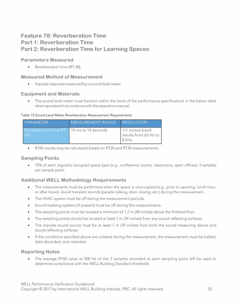
Table 15 Sound Level Meter Reverberation Measurement Requirements
PARAMETER MEASUREMENT RANGE RESOLUTION
Reverberation time (RT
60)
10 ms to 14 seconds 1/1 octave band
results from 63 Hz to
8 kHz
• RT60 results may be calculated based on RT20 and RT30 measurements.
Sampling Points
• 10% of each regularly occupied space type (e.g., conference rooms, classrooms, open offices), 3 samples
per sample point.
Additional WELL Methodology Requirements
• The measurements must be performed when the space is unoccupied (e.g., prior to opening, lunch hour,
or after hours). Avoid transient sounds (people talking, door closing, etc.) during the measurement.
• The HVAC system must be off during the measurement periods.
• Sound masking systems (if present) must be off during the measurements.
• The sampling points must be located a minimum of 1.2 m (48 inches) above the finished floor.
• The sampling points should be located at least 1 m (39 inches) from any sound-reflecting surfaces.
• The impulse sound source must be at least 1 m (39 inches) from both the sound measuring device and
sound reflecting surfaces.
• If the conditions specified above are violated during the measurement, the measurement must be halted,
data discarded, and restarted.
Reporting Notes
• The average RT60 value at 500 Hz of the 3 samples recorded at each sampling point will be used to
determine compliance with the WELL Building Standard threshold.
WELL Performance Verification Guidebook
Copyright © 2017 by International WELL Building Institute, PBC. All rights reserved. 36
Feature 79: Sound Masking
Part 2: Sound Masking Limits
Parameters Measured
• A-weighted time-averaged sound pressure level (dBA)
Measured Method of Measurement
• Sound level meter
Equipment and Materials
• The sound level meter must function within the limits of the performance specifications in the below table
when operated in accordance with the operation manual.
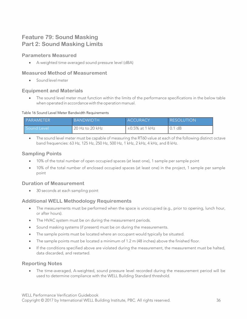
Table 16 Sound Level Meter Bandwidth Requirements
PARAMETER BANDWIDTH ACCURACY RESOLUTION
Sound Level 20 Hz to 20 kHz ±0.5% at 1 kHz 0.1 dB
• The sound level meter must be capable of measuring the RT60 value at each of the following distinct octave
band frequencies: 63 Hz, 125 Hz, 250 Hz, 500 Hz, 1 kHz, 2 kHz, 4 kHz, and 8 kHz.
Sampling Points
• 10% of the total number of open occupied spaces (at least one), 1 sample per sample point
• 10% of the total number of enclosed occupied spaces (at least one) in the project, 1 sample per sample
point
Duration of Measurement
• 30 seconds at each sampling point
Additional WELL Methodology Requirements
• The measurements must be performed when the space is unoccupied (e.g., prior to opening, lunch hour,
or after hours).
• The HVAC system must be on during the measurement periods.
• Sound masking systems (if present) must be on during the measurements.
• The sample points must be located where an occupant would typically be situated.
• The sample points must be located a minimum of 1.2 m (48 inches) above the finished floor.
• If the conditions specified above are violated during the measurement, the measurement must be halted,
data discarded, and restarted.
Reporting Notes
• The time-averaged, A-weighted, sound pressure level recorded during the measurement period will be
used to determine compliance with the WELL Building Standard threshold.

WELL Performance Verification Guidebook
Copyright © 2017 by International WELL Building Institute, PBC. All rights reserved. 37
VISUAL VERIFICATIONS AND SPOT CHECKS
The WELL Building Standard Appendix D Feature Types and Verification Methods indicates which Features and
Parts require visual verifications and spot checks. In addition, all Features, regardless of Appendix D, are potentially
subject to verification on-site: if a Feature’s documentation was approved in Documentation Review and Appendix
D does not list any on-site checks for the Feature, the WELL Assessor may still mark the Feature as pending
clarifications in the Performance Verification report if he/she identifies evidence while on-site that the building may
not be in compliance with the requirements of that Feature.
Visual Inspections
For Features and Parts that require visual verification, the requirements will be visually verified by the WELL Assessor
while on-site in all spaces/locations of the project where the Requirements are applicable.
For example, for Feature 8 Healthy Entrance Part 1 Permanent Entryway Walk-Off Systems, the WELL Assessor will
verify the requirements at all applicable project entrances.
Spot Checks
The WELL Building Standard Appendix D Feature Types and Verification Methods indicates which Features and
Parts require spot checks. For Features and Parts that require spot checks, the requirements will be verified by the
WELL Assessor while on-site in at least one part/location of the project where the requirements are applicable.
For example, for Feature 57 Low-Glare Workstation Design, Part 2 Daylight Management, the WELL Assessor will
verify the requirements at a sample of workstations/computer screens included in the project.
WELL Performance Verification Guidebook
Copyright © 2017 by International WELL Building Institute, PBC. All rights reserved. 38
SPECIAL CONSIDERATION FOR MULTIFAMILY RESIDENTIAL
For multifamily residential buildings, initial Performance Verification will involve sampling from randomly
determined locations in the entire building. However, the scope of Performance Verification during the
recertification process will be limited to components of the common areas only (the interiors of occupied living
spaces will not be subject to on-site sampling).
Tentative testing locations are typically selected by the WELL Assessor prior to arrival on site. However, these
tentative testing locations are subject to change once the WELL Assessor arrives on site, based on the observed
conditions.
Whenever a calculation results in a fractional sampling point, round up to the next whole number. Additionally,
please note that the number of sampling locations represents a minimum. The WELL Assessor may include
additional sampling points.
Project team need to determine how many different unit types there are based on the following criteria. Every
dwelling unit of each unit type must:
• Be under the same ownership and management
• Be part of the same construction contract
• Use the same heating and ventilation methods
• Use the same building materials, finishes, and furnishings throughout
Each unit of a given unit type may differ in layout and size (e.g. number of bedrooms, window placements, ceiling
heights, difference in area
Feature 01:
• Projects with 10 units or fewer: Two of each unit type
• Projects with more than 10 units: Three of each unit type with a minimum of 5% of units and a maximum
of 40 units
• At least two of each unit type or a minimum of 25% of each unit type must be ‘major’ sampling zones
Features 30/31/32/33/37:
• Projects with 20 units or fewer: One unit
• Projects with 21-100 units: 5% of units
• Projects with more than 100 units: Case by case basis
Features 53/54/74/75:
Sampling should be distributed between different unit types. At least one of each type of room described in the
feature in each unit is evaluated.
• Projects with 15 units or fewer: Four units
• Projects with more than 16-50 units: 25% of the units
• Projects with more than 51-100 units: 15% of the units
• Projects with more than 100 units: Case by case basis

WELL Performance Verification Guidebook
Copyright © 2017 by International WELL Building Institute, PBC. All rights reserved. 39
Feature 54 (special considerations):
Take four samples at orthogonal directions and use the highest value for certification purposes. Note that compliance
for both Part 1a and Part 1b will require testing with two brightness settings in the lighting system, or by using two
independently controllable fixtures.
WELL Performance Verification Guidebook
Copyright © 2017 by International WELL Building Institute, PBC. All rights reserved. 40
APPENDIX A
i . Sampling Zone Selection
Feature 1: Air Quality Standards Sampling Zone Selection
Sampling zones are areas of the project site selected for assessment by the WELL Assessor for performance testing
required in Feature 1 Air Quality Standards. Sampling zones are representative of the project site, and include all
categories of room types within the WELL project. Note that visual inspections and spot-checks and measurements
are not limited to specific sampling zones, and instead occur throughout the WELL project within the scope defined
in section II of this guidebook.
Sampling zones are defined as an entire floor or an area of a floor space measuring up to 25,000 square feet,
whichever area is smaller. A single sampling zone will never be larger than 25,000 square feet. Sampling zones are
contiguous and remain on one floor. Floors (if large enough) may contain more than one sampling zone but
sampling zones should not overlap. Sampling zones may contain multiple rooms and/or room types. The minimum
number of sampling zones required for any project is two.
If a floor plate is over 25,000 square feet, the additional space will be added as a sampling zone and all zones on
that floor plate will be designated in a way that results in similarly-sized sampling zones. For example, a 63,000-
square foot floor plate would include three sampling zones, each of approximately 21,000 square feet.
When delineating sampling zones, the WELL Assessor should use professional judgment (based on knowledge of
the space gained through prior review of floor plans and observations made during an initial walk-through) to draw
a zone that encompasses the centers of activity of the space.
Determining the Number of Sampling Zones
The number of sampling zones is dependent on the total number of floors and total square footage of the project
site. Within the project site, every 25,000 square feet or entire floor plate, whichever floor space is smaller, qualifies
as a sampling zone.
Selection of Major and Minor Sampling Zones
At least 25% of all sampling zones within a project must be selected as major sampling zones and each project
must have at least two major sampling zones. The remaining 75% of zones are minor zones. The distribution of
major zones should be representative of the project as a whole.

WELL Performance Verification Guidebook
Copyright © 2017 by International WELL Building Institute, PBC. All rights reserved. 41
ii . Number of Sample Points
Feature 53: Visual Lighting Design Part 1 Visual Acuity for Focus
Feature 54: Circadian Lighting Design Part 1 Melanopic Light Intensity for Work Areas
Assume a hypergeometric distribution of measurements.
E = Confidence Interval (Margin of error) = ±10% Confidence Level = 90%
Z = Z Score corresponding to 90% confidence level = 1.65
P = proportion of events in population = assume 0.5
Q = proportion of non-events in population = assume 0.5
N = total population size
Number of required sample points, 𝑛 =𝑁𝑧2𝑝𝑞
𝐸2(𝑁−1)+𝑧2𝑝𝑞=
68𝑁
𝑁+67
i. U.S. Environmental Protection Agency. Quality Assurance Handbook for Air Pollution Measurement
Systems. http://www3. epa.gov/ttnamti1/files/ambient/pm25/qa/QA-Handbook-Vol-II.pdf. Published May
2013. Accesses October 20, 2015.
ii. U.S. Environmental Protection Agency. Quality Assurance Handbook for Air Pollution Measurement
Systems. http://www3. epa.gov/ttnamti1/files/ambient/pm25/qa/QA-Handbook-Vol-II.pdf. Published May
2013. Accesses October 20, 2015.

International WELL Building Institute22 Little West 12th Street, New York, New York 10014
www.wellcertified.com