peristaltic pump assembly and operating instructions flex df4a
TRANSCRIPT

Peristaltic pumpDULCO®flex DF4a
Assembly and operating instructions
A2536
EN
Original operating instructions (2006/42/EC)Part no. 986513 BA DX 026 04/18 EN
Please carefully read these operating instructions before use. · Do not discard.The operator shall be liable for any damage caused by installation or operating errors.
The latest version of the operating instructions are available on our homepage.

In order to make it easier to read, this document uses the maleform in grammatical structures but with an implied neutral sense. Itis aimed equally at both men and women. We kindly ask femalereaders for their understanding in this simplification of the text.
Please read the supplementary information in its entirety.
Information
This provides important information relating to thecorrect operation of the unit or is intended to makeyour work easier.
Warning informationWarning information includes detailed descriptions of the haz‐ardous situation, see Ä Chapter 3.1 ‘Labelling of Warning Informa‐tion’ on page 10.The following symbols are used to highlight instructions, links, lists,results and other elements in this document:
Tab. 1: More symbolsSymbol Description
Action, step by step.
Outcome of an action.
Links to elements or sections of these instructions or other applicable documents.
n List without set order.
[Button] Display element (e.g. indicators).Operating element (e.g. button, switch).
‘Display /GUI’ Screen elements (e.g. buttons, assignment of function keys).
CODE Presentation of software elements and/or texts.
General non-discriminatory approach
Supplementary information
Supplemental directives
2

Table of contents1 About this product................................................................. 5
1.1 Nameplate.................................................................... 61.2 Construction and functional description........................ 61.3 Overview of equipment and control elements............... 7
2 Identity code.......................................................................... 83 Safety chapter..................................................................... 10
3.1 Labelling of Warning Information................................ 103.2 User qualification........................................................ 123.3 General safety information.......................................... 133.4 Intended use............................................................... 14
4 Storage and transport......................................................... 154.1 Storage....................................................................... 154.2 Transport.................................................................... 154.3 Packaging material..................................................... 15
5 Assembly and installation................................................... 165.1 Dimensional drawing.................................................. 175.2 Assembly.................................................................... 185.3 Installation, hydraulic.................................................. 195.4 Installation, electrical.................................................. 215.4.1 Opening the housing................................................ 215.4.2 Preparing for mains connection (equipment without
mains plug).............................................................. 215.4.3 Additional connections............................................. 225.4.4 Close the housing.................................................... 25
6 Commissioning................................................................... 267 Setting................................................................................. 28
7.1 Control unit................................................................. 287.1.1 LCD display............................................................. 287.1.2 LED.......................................................................... 297.1.3 Control keys............................................................. 297.2 Continuous displays.................................................... 317.2.1 Chemical pump........................................................ 317.2.2 Active carbon pump or flocculant pump................... 327.2.3 Setting options for the continuous display............... 337.3 Operating menu.......................................................... 347.3.1 Operating menu overview........................................ 367.3.2 Modifying the operating mode ( ‘MODE’ menu)....... 387.3.3 Changing parameters ( ‘SET’ menu)....................... 387.3.4 Changing the configuration ( ‘CONFIG’ menu)........ 427.3.5 Service menu ( ‘SERVICE’ menu)........................... 447.3.6 Reading system information ( ‘INFO’ menu)............ 457.3.7 Security-relevant settings ( ‘SECURITY’ menu)...... 467.3.8 Calibrating the pump (CALIBRATION menu).......... 48
8 Operation............................................................................ 499 Maintenance....................................................................... 5010 Troubleshooting.................................................................. 53
10.1 Errors without error messages.................................. 5310.2 Faults with error messages....................................... 53
Table of contents
3

10.3 Warning with error message..................................... 5410.4 All other faults........................................................... 54
11 Decommissioning and disposal.......................................... 5511.1 Use Parts Disposal/Declaration of Decontamina‐
tion............................................................................ 5612 Technical data..................................................................... 57
12.1 Performance data..................................................... 5712.2 Precision................................................................... 5712.3 Dimensions and weights........................................... 5712.4 Material specifications.............................................. 5812.5 Ambient conditions................................................... 5812.6 Degree of protection and safety requirements.......... 5912.7 Electrical data........................................................... 5912.8 Sound pressure level................................................ 60
13 Ordering information for spare parts/accessories............... 6114 Declaration of Conformity for Machinery............................. 6215 Overview of setting parameters.......................................... 6316 Index................................................................................... 67
Table of contents
4

1 About this productThe assembly and operating instructions for the peristaltic pumpDULCO®flex DF4a are targeted at people who, at the very least,have the qualifications of a trained person, see Ä Chapter 3.2‘User qualification’ on page 12. Should higher qualifications benecessary, then this fact is described at the start of a chapter.
The printed version of the assembly and operating instructions isnaturally not updated. We would therefore ask you to regularly visitthe manufacturer’s homepage www.prominent.com to find outabout the new electronic versions of the assembly and operatinginstructions. These versions may contain, among other things,information about new fault remedies or spare parts.
The peristaltic pump DULCO®flex DF4a is a pump designed formetering liquids. The feed chemical is pumped by the rotorsqueezing on the hose. No valves are needed for this, whichensures gentle handling of the feed chemical.
A2537
Fig. 1: DULCO®flex DF4aTypical applications include processes where only a low feed pres‐sure is required.The metering pump features several inputs for setting the capacity.The step motor means that the capacity can be set continuouslyvariably.The key features:n Capacity range 0.5 – 12 l/h, 4 ... 2 bar.n PharMed® hose material.n Step motor, speed-controlled.n Continuously variable adjustment of the capacity either man‐
ually or externally via contacts or analogue signal 0/4 ... 20 mAand 0 ... 10 V.
n Priming function (high-speed run).n Spring-mounted rollers for uniform roller pressure and
increased service life of the hose.n Selectable capacity adjustment, e.g. increase as required or
night set-back.n Capacity appears on the display in l/h.n Reverse direction of rotation, among other things useful for
backflushing.n Housing degree of protection IP 65.
The target group
Assembly and operating instructions
The peristaltic pump
About this product
5

1.1 Nameplate
A2547
Fig. 2: NameplateThe nameplate provides information on:n Manufacturer with address and phone numbern Place and country of origin,n Manufacturing date in week/yearn Type of pump with identity code [Type],n Electrical connection [EL. ANSCHLUSS] in Volts / Hertz, watts
and ampsn Serial number [SER.NR. / TN.]n Capacity [DOSIERLEISTUNGLEISTUNG] in bar and psi and/or
l/h and gphn [IP65] degree of protection.
1.2 Construction and functional descriptionThe pump comprises three main components:n Drive unit (step motor)n Liquid end (rotor, rollers and pump hose)n Control unitThe pump features a plastic housing. The plastic housing com‐prises an upper and lower part, which are screwed together. Thelower part contains the PCBs for the motor control. The upper partof the housing accommodates the motor and display PCB with dis‐play and keys.The liquid end is mounted at the front and is sealed by a screw-ontransparent cover. The pump hose can easily be replaced after thetransparent cover has been removed.The step motor drives the rotor. Two spring-mounted rollers at theends of the rotor press against the pump housing. The pump hoseruns along the inner curve of the dosing head.The rotary movement of the rotor alternately presses and releasesthe rollers in relation to the pump hose. The liquid is drawn in bysuction and pumped into the pressure hose.The pump is operated by the control unit. The required meteringlevel and operating mode are set on the control unit. Metering iscontrolled by the control unit or by an external contact, level and/orpause input.
About this product
6

1.3 Overview of equipment and control elements
P_DX_0032_SW_2
1
1312
11 10 9 8
765432
Fig. 3: Overview of DF4a equipment. A) Front view, B) Side view / Functional plug for “Level” socket1 Rotor2 Control keys3 LCD display4 Housing lower part5 Housing upper part6 Liquid end7 Transparent cover
8 Pressure connector9 “Level” socket, if required with functional plug for
the “Level” socket10 Leakage fitting with end cap11 Suction connector12 Hose rupture monitoring device13 Pump hose
About this product
7

2 Identity codeProduct range DULCO®flex DF4a
DF4a Applications
0 Chemical pump
A Metering of active carbon
F Metering of flocculants
Installation type
W Wall-mounted
Design
0 with ProMinent® logo
1 without ProMinent® logo
Type Pump capacity
bar l/h
04004 4.0 0.35
04015 4.0 1.50
03060 2.5 6.00
02120 2.0 12.00
Hose material
P PharMed®
Hydraulic connector
0 Standard
9 Special connection 10x4 discharge side
Operating voltage
U 100 - 240 VAC, 50/60 Hz
Cable and plug
0 without cable
1 with cable 2 m; open end
A with 2 m cable; standard European plug
B with 2 m cable; standard Swiss plug
Accessories
0 no accessories
2 with lip-seal metering valve PCB and 10 m PEmetering line
Hardware extension
0 none
Default language
00 language-neutral
Relay
1 Fault indicating relay (N/C)
Identity code
8

Product range DULCO®flex DF4a
3 Fault indicating relay (N/O)
Control version
8 manual + external contactand analogue 0/4-20 mA +0-10 V
C as 8 and CANopen
D as 8 and CANopen and CANconnector
Additional inputs
1 Pause + 2-stage level +AUX_1
2 Pause + 1-stage level +AUX_1 + AUX_2
Pause/level
0 Pause N/C + levelN/C
Certification
01 CE mark
Identity code
9

3 Safety chapter
3.1 Labelling of Warning InformationThese operating instructions provide information on the technicaldata and functions of the product. These operating instructions pro‐vide detailed warning information and are provided as clear step-by-step instructions.The warning information and notes are categorised according tothe following scheme. A number of different symbols are used todenote different situations. The symbols shown here serve only asexamples.
DANGER!Nature and source of the dangerConsequence: Fatal or very serious injuries.Measure to be taken to avoid this danger.Description of hazard– Denotes an immediate threatening danger. If
the situation is disregarded, it will result in fatalor very serious injuries.
WARNING!Nature and source of the dangerPossible consequence: Fatal or very serious inju‐ries.Measure to be taken to avoid this danger.– Denotes a possibly hazardous situation. If the
situation is disregarded, it could result in fatalor very serious injuries.
CAUTION!Nature and source of the dangerPossible consequence: Slight or minor injuries.Material damage.Measure to be taken to avoid this danger.– Denotes a possibly hazardous situation. If the
situation is disregarded, it could result in slightor minor injuries. May also be used as awarning about material damage.
NOTICE!Nature and source of the dangerDamage to the product or its surroundings.Measure to be taken to avoid this danger.– Denotes a possibly damaging situation. If the
situation is disregarded, the product or anobject in its vicinity could be damaged.
Introduction
Safety chapter
10

Type of informationHints on use and additional information.Source of the information. Additional measures.– Denotes hints on use and other useful informa‐
tion. It does not indicate a hazardous or dam‐aging situation.
Safety chapter
11

3.2 User qualification
WARNING!Danger of injury with inadequately qualified per‐sonnelThe operator of the system / equipment is respon‐sible for ensuring that the qualifications are ful‐filled.If inadequately qualified personnel work on the unitor loiter in the hazard zone of the unit, this couldresult in dangers that could cause serious injuriesand material damage.– All work on the unit should therefore only be
conducted by qualified personnel.– Unqualified personnel should be kept away
from the hazard zone.The pertinent accident prevention regulations, aswell as all other generally acknowledged safetyregulations, must be adhered to.
Training Definition
Instructed personnel An instructed person is deemed to be a person who has been instructed and,if required, trained in the tasks assigned to him and possible dangers thatcould result from improper behaviour, as well as having been instructed in therequired protective equipment and protective measures.
Trained user A trained user is a person who fulfils the requirements made of an instructedperson and who has also received additional training specific to the systemfrom the manufacturer or another authorised distribution partner.
Trained, qualified per‐sonnel
A trained, qualified employee is deemed to be a person who is able to assessthe tasks assigned to him and recognize possible hazards based on histraining, knowledge and experience, as well as knowledge of pertinent regula‐tions. A trained, qualified employee must be able to perform the tasksassigned to him independently with the assistance of drawing documentationand parts lists. The assessment of a person's technical training can also bebased on several years of work in the relevant field.
Electrical technician An electrical technician is able to complete work on electrical systems and rec‐ognise and avoid possible dangers independently based on his technicaltraining and experience as well as knowledge of pertinent standards and regu‐lations. An electrical technician must be able to perform the tasks assigned tohim independently with the assistance of drawing documentation, parts lists,terminal and circuit diagrams. The electrical technician must be specificallytrained for the working environment in which the electrical technician isemployed and be conversant with the relevant standards and regulations.
Service The Service department refers to service technicians, who have receivedproven training and have been authorised by the manufacturer to work on thesystem.
Safety chapter
12

3.3 General safety information
WARNING!Danger from hazardous substances!Possible consequence: Fatal or very serious inju‐ries.Please ensure when handling hazardous sub‐stances that you have read the latest safety datasheets provided by the manufacture of the haz‐ardous substance. The actions required aredescribed in the safety data sheet. Check thesafety data sheet regularly and replace, if neces‐sary, as the hazard potential of a substance can bere-evaluated at any time based on new findings.The system operator is responsible for ensuringthat these safety data sheets are available and thatthey are kept up to date, as well as for producingan associated hazard assessment for the worksta‐tions affected.
CAUTION!Warning of feed chemical spraying aroundFeed chemical can spray out of the hydraulic com‐ponents if they are tampered with or opened due topressure in the liquid end and adjacent parts of thesystem.Depressurise, drain and flush the hydraulic sectionprior to undertaking work on the system.
n The pump is not designed to meter gaseous media or solids.n Never use the pump outdoors without additional protection
(outer housing, weather protection roof).n Only allow trained and authorised personnel to operate the
pump.n You have a responsibility to adhere to the information con‐
tained in the operating instructions at the different phases ofthe unit's service life.
The transparent cover on the liquid end protects personnel fromthe rotating rotor and prevents feed chemical escaping in the eventof a hose rupture.
In the event of an emergency, disconnect the mains plug or pressthe emergency stop switch.If feed chemical escapes, ensure that the hydraulic environmentaround the pump is at atmospheric pressure as well. Refer to thematerial safety data sheet for the feed chemical.
Safety information
Protective equipment
Information in the event of an emer‐gency
Safety chapter
13

3.4 Intended usen Only use the pump to meter liquid feed chemicals.n Only use the system in accordance with the technical data and
specifications outlined in the operating instructions.n Only use the pump if it has been correctly installed and started
up.n All other uses or modifications are prohibited.
Safety chapter
14

4 Storage and transport4.1 Storage
User qualification: instructed user, see Ä Chapter 3.2 ‘User qualifi‐cation’ on page 12Permissible ambient temperature: - 10 °C ... +55 °C.Humidity: maximum 95% relative air humidity, non-condensing.Other ambient conditions: No dust, no direct sunlight.
4.2 TransportThe sensor should be transported in its original packaging and incompliance with the permissible environmental conditions. No fur‐ther special conditions have to be observed in relation to transport.
4.3 Packaging materialDispose of packaging material in an environmentally responsibleway. All packaging components carry the corresponding recyclingcode .
Storage and transport
15

5 Assembly and installationn User qualification: trained qualified personnel or electrical tech‐
nician, Ä Chapter 3.2 ‘User qualification’ on page 12
WARNING!Carry out mechanical and hydraulic assembly workbefore commencing the electrical installation.
OutdoorsThe unit is resistant to normal atmospheres inplant rooms.Always use a housing or weatherproof cover whenoperating the unit outdoors.
P_DX_0033_SW
136
17688
Fig. 4: DF4a drilling points - dimensions in mm (not true to scale).
Assembly and installation
16

5.1 Dimensional drawing
P_DX_0037_SW
22659
125,4
2916
2
165
Fig. 5: Dimensional drawing of DF4a - dimensions in mm (not true to scale)
Assembly and installation
17

5.2 Assemblyn User qualification: trained qualified personnel, Ä Chapter 3.2
‘User qualification’ on page 12
P_DX_0034_SW
5,2
Fig. 6: Wall-mounted, parked position - dimensions in mm (not trueto scale).1. Mark the drill holes on the wall - see Fig. 4.2. Drill the Ø 8 mm holes and position the rawlplugs supplied -
see Fig. 6.3. Screw a cheese-head screw into the upper drill hole. The
screw head should then have an approx. 5.2 mm gap fromthe wall.
4. Suspend the top of the unit into the screw head.
Carefully remove the upper part of the housingfrom the lower part of the housing to avoid tearingthe ribbon cable.
A2569
Fig. 7: 4 screws (arrows) on the upper part of the housing5. To do this, loosen the 4 screws (arrows) on the upper part of
the housing.
Assembly and installation
18

A2570
3
21
Fig. 8: Parked position6. Slide the upper part of the housing (1) with the side flaps (3)
up into the recesses in the lower part of the housing (2)(parked position).
7. Screw the right and left side of the unit to the wall using theremaining screws.
8. Close the housing, Ä Chapter 5.4.4 ‘Close the housing’on page 25
5.3 Installation, hydraulicn User qualification: trained qualified personnel, Ä Chapter 3.2
‘User qualification’ on page 12
CAUTION!Warning of escaping feed chemicalFeed chemical can escape in the event that thehose lines are incorrectly installed.– Only use original hoses with the specified hose
dimensions 6 x 4 mm or 10 x 4 mm.– Avoid reducing the hose sizes.– Only use hose lines capable of withstanding
twice the operating pressure of the peristalticpump.
1. Connect the discharge line to the right hose connector (1).2. Connect the suction line to the left hose connector (4).
Installing the suction and meteringlines:
Assembly and installation
19

ProMin
entR
A2563
5
32
4
1
Fig. 9: Assembling the suction and metering line3. Shorten the end of the hose at right angles.4. Unscrew the union nut (2) and slide the union nut over the
hose (3).5. Push the hose end over the hose connector (4) as far as the
stop.6. Tighten the union nuts.7. If you are only using a hose line and not a suction lance:
Shorten the free end of the suction line so that the end of thesuction line hangs just above the base of the feed chemicalstorage tank.
8. If necessary, feed a hose line from the leakage fitting (5)back into the feed chemical storage tank.
Assembly and installation
20

5.4 Installation, electricaln User qualification: trained electrical technician, Ä Chapter 3.2
‘User qualification’ on page 12
WARNING!Danger of electric shockThe operator must fit an RCD or another suitablemeasure to protect personnel and equipment.
WARNING!Unexpected start-up is possibleThe pump can start pumping and consequentlyfeed chemical may escape as soon as the pump isconnected to the mains/power supply.– Avoid the escape of feed chemical.– If you have not done so, immediately press
[STOP/START] or disconnect the pump fromthe mains voltage e.g. using an EmergencyStop switch.
– Refer to the material safety data sheet for yourfeed chemical.
Equipment with a mains plug is connected to the mains power by asuitable socket. Equipment without a mains plug needs to be elec‐trically installed, Ä Chapter 5.4.1 ‘Opening the housing’on page 21.
5.4.1 Opening the housing1. Allow the equipment to cool down before working on it.2. Loosen the 4 screws on the upper part of the housing, Fig. 7.3. Slide the upper part of the housing with the side flaps up into
the recesses in the lower part of the housing (parked posi‐tion), Fig. 8.
5.4.2 Preparing for mains connection (equipment without mains plug)Provide a suitable mains cable with appropriate fuse and circuitbreaker.1. Ensure that the mains power cable is de-energised and
remains so.2. Check that the supply cables have metric threaded connec‐
tors. Terminal area - Ä Chapter 12 ‘Technical data’on page 57.Use a screwdriver to break out the small drill hole at the farright on the underside of the back section.
3. Screw in the corresponding threaded connector and tighten it– do not tighten the clamping screw.
4. Insert the reducing insert into the threaded connectordepending on the cable cross-section used.
Assembly and installation
21

5. Cable ends without cable end sleeves can loosen over aperiod of time and come into contact with other cable ends.n Only use cables with suitable cable end sleeves (0.75
mm2).Guide the mains cable into the threaded connector.
6. Connect the mains cable to terminal block XP1 - see Fig. 10.7. Tighten the clamping screw so that the threaded connector is
moisture-proof.
P_DX_0035_SW1 2Fig. 10: Preparing the mains connection1 Break-out drill holes2 Terminal block XP1
5.4.3 Additional connectionsAdditional units can be connected to the metering pump’s terminalblocks - see Ä Chapter 5.4.3.1 ‘Wiring diagram’ on page 23.n Pause inputn Level input: Level fault, Level warning (only in the event that
the level input is operated with two stages).n Switched capacity change, for instance night setback (AUX1)
or increased capacity (AUX2)n Alarm relay.n External input for control by analogue signal.
Risk of short circuit
Assembly and installation
22

The external changeover terminal blocks for level input and pauseinput react differently depending on the delivery status. In the eventthat the pause input is factory-configured as a normally open con‐tact (N/C) (default: ‘ NORM.CLOSE’ ), then a contact jumper is pre-installed on the corresponding terminal block. This means that thepump can be installed and operated immediately.The contact jumper may need to be removed when wiring the unit.
A suction lance with a ProMinent® round plug can be inserteddirectly into the “Level” socket.
5.4.3.1 Wiring diagram
P_DX_0036_SW_2
Fig. 11: Wiring diagram for DF4aA Limit, Internal/External housing1 Input, mains voltage 100 ... 240 V2 Output, alarm relay3 Input, external contact (frequency)4 Input, external 0 ... 10 V5 Input, external 0/4 ... 20 mA6 Input, level warning or capacity change AUX_2
7 Input, level fault8 Input, level 2-stage* - see Fig. 129 Input, contact or capacity change ‘AUX_1’10 Input, pause* If you are using a suction lance with an open
lead.
Assembly and installation
23

If you are using a suction lance with an open lead or if you have aplug that does not fit, you can cut off this plug and connect thecable leads directly to the terminals, Fig. 12.
P_DX_0038_SW
bn bu bk
GND
AEr Wa
XK3 XK4
1 22 1
Fig. 12: Example: Terminal wiring diagram for ProMinent® 2-stage level switchEr Fault, level 2Wa Warning, level 1A Limit, Internal/External housing
bn Brown, cable colour, (Fault, level 2)bu Blue, cable colour, (Warning, level 1)bk Black, cable colour, (Earth GND)
5.4.3.2 Level inputUse a two-stage suction lance with round plug.
A suction lance with a ProMinent® round plug can be inserteddirectly into the “Level” socket.
Use a single-stage suction lance with round plug.
A suction lance with a ProMinent® round plug can be inserteddirectly into the “Level” socket.
Dismantle the “Level” socket on the pump housing to connect asuction lance with lead.Use an M12 threaded cable connector provided to guide the cablethrough and connect the leads in accordance with the wiring dia‐gram, Fig. 12
If no suction lance was connected, the functional plug must remaininserted at the “Level” socket as the pump will not otherwiseoperate.
Connection without round plug
a) Suction lance with pre-warning andround plug, identity codeDF4axxxXXXXXxxUxx000xx1x
a) Suction lance without pre-warningand round plug, identity codeDF4axxxXXXXXxxUxx000xx2x
c) Suction lance with lead
d) No suction lance
Assembly and installation
24

5.4.4 Close the housing1. Place the upper part of the housing onto the lower part of the
housing.2. Manually tighten the 4 screws, approx. 3.5 Nm.
WARNING!Danger of electric shockIP 65 degree of protection cannot be ensured if theseal is not properly fitted.– Close the housing leak-tight after all work.– Check that the seal is correctly fitted.
3. Check that the seal is correctly fitted.
Assembly and installation
25

6 Commissioningn User qualification: trained user Ä Chapter 3.2 ‘User qualifica‐
tion’ on page 12
WARNING!Danger from hazardous substances!Possible consequence: Fatal or very serious inju‐ries.Please ensure when handling hazardous sub‐stances that you have read the latest safety datasheets provided by the manufacture of the haz‐ardous substance. The actions required aredescribed in the safety data sheet. Check thesafety data sheet regularly and replace, if neces‐sary, as the hazard potential of a substance can bere-evaluated at any time based on new findings.The system operator is responsible for ensuringthat these safety data sheets are available and thatthey are kept up to date, as well as for producingan associated hazard assessment for the worksta‐tions affected.
CAUTION!Crushed fingersThe rotating rotor can crush fingers.– Only operate the pump with the transparent
cover fixed in place.
Only operate the pump once it has been properly installed. Thismeans:n The pump has been assembled properly, as described in
chapter Ä Chapter 5.2 ‘Assembly’ on page 18.n The pump has been hydraulically installed properly, as
described in chapter Ä Chapter 5.3 ‘Installation, hydraulic’on page 19.
n The pump has been electrically installed properly, as describedin chapter Ä Chapter 5.4 ‘Installation, electrical’ on page 21.
n A sufficient volume of feed chemical is available and thestorage tank is connected to the pump.
n The process into which the feed chemical is to be meteredshould be operating safely and properly (temperature, circula‐tion output etc. within normal parameters).
n The operating personnel has been selected and trained by theoperator, see Ä Chapter 3.2 ‘User qualification’ on page 12
Commissioning
26

1. Check that everything has been properly fitted.2. Set up the pump as is sensible and necessary for your
metering process, see chapters Ä Chapter 7.3.2 ‘Modifyingthe operating mode ( ‘MODE’ menu)’ on page 38 andÄ Chapter 7.3.1 ‘Operating menu overview’ on page 36.
Operatingmode
Property Typical application
‘MANUAL’ In ‘MANUAL’ operating mode, the pump works with aconstant capacity.
Metering of sauna oils or fra‐grances
‘ANALOG’ In ‘ANALOG’ operating mode, the pump works withthe circulation output of the circulating pump as a ref‐erence variable. The reference variable is controlledby the external input.
Metering of chemicals, e.g. floccu‐lants, active carbon.
‘CONTACT’ Contact signals are provided by the external input in‘CONTACT’ operating mode. The pump meters theset volume per contact ( ‘VOLUM’ menu).
Metering of chemicals, e.g.sodium-calcium hypochlorite,H2O2, acid. Controlled by a meas‐uring/control unit.
Press [Start/Stop] to start or stop the pump in the respectivemode. In stopped mode, ‘STOP’ appears in the second lineof the LCD display.
3. Press both [arrow keys] simultaneously to prime the feedchemical until the pump hose is filled.
4. Use [Start/Stop] to start the pump.
Commissioning
27

7 Setting7.1 Control unit
The unit is operated by the control unit on the right side of the unit.
P_DX_0031_SW
1
322
Fig. 13: Control unit1 LCD display2 LED3 Control keys
7.1.1 LCD displayThe LCD display consists of a two-line display. The brightness ofthe LCD display can be adjusted - see chapter entitled "Adjustingthe LCD contrast".
Tab. 2: The displayed symbols have the following meanings:Symbol Meaning
[P] is active.Press the key to move to the next parameter.
The [DOWN] and [UP] arrow keys are active.
The [DOWN] arrow key is active.The maximum value or the uppermost sub-menu has been reached.
The [UP] arrow key is active.The minimum value or the lowermost sub-menu has been reached.
Setting
28

7.1.2 LEDTab. 3: The unit LEDs (left) show the following information:LED Information
off No supply voltage
steady green Pump ready and stopped
flashing green Pump ready and running
steady red Fault, metering stopped
steady orange Level error; storage tank is empty; pump stopped
flashing orange Level warning
Tab. 4: The control LED (right) shows the following information (signals as soon as the unit is connected tothe mains/power supply):LED Information
green - short,red - 1 second,off
System OK
7.1.3 Control keys
Return to the continuous displayIf you press and hold down the key for 3 sec‐onds or do not press a key for 1 minute, then thepump exits the menu and returns to the continuousdisplay.
The control keys are designated as follows:
Tab. 5: Descriptions of the control keysKey Description
[START/STOP]
[DOWN]
[UP]
[P]
Setting
29

The control keys have different functions in the continuous display,in the operating menu and in the sub-menus:
Tab. 6: Function of the control keys in conjunction with the continuous displayKey Functions
DOWN
Lower / change the set value
UP
Increase / change the set value
Move to the next menu item
Tab. 7: Function of the control keys in conjunction with the operating menuKey Functions
DOWN
Move to the next sub-menu
UP
Move to the previous sub-menu
Open sub-menu (switch to the first item of the selected sub-menu).
Tab. 8: Function of the control keys in a menu item of a sub-menuKey Functions
DOWN
Lower / change the set value
UP
Increase / change the set value
Accept the set value and move to the next menu item of the sub-menu
Tab. 9: [P] key - additional generally-applicable functions:Pressing dura‐tion
Function
approx. 2 sec‐onds
Open the operating menu, only possible when the pump is stopped.
approx. 3 sec‐onds
Exit the operating menu without saving the set values and return to the continuous dis‐play
approx. 5 sec‐onds
Sets the contrast of the LCD display to the default value
approx. 10 sec‐onds
Restores the delivery state
A modified set value is only carried over if the set value has previ‐ously been confirmed by pressing [P].
Setting
30

7.2 Continuous displays7.2.1 Chemical pump
→
→
→
Display in MANUAL mode
Display in ANALOG mode
Display in STOP mode (calibrated)
Display in CONTACT mode
Concentration activated (calibrated)
Display in START mode (calibrated)
Fig. 14: Overview of continuous displays
Continuous display “ Manual” operating mode “ Contact” operating mode“ Analogue” operating mode
Metering volume
Capacity
Volume counter
Remaining volume
Signal current (at the contact input)
Concentration
Fig. 15: Continuous displays in STOP status
Setting
31

7.2.2 Active carbon pump or flocculant pump
>8 sec.
→
Display in MANUAL mode
Display in ANALOG mode
Display in STOP mode
Display in CONTACT mode
No input
Display in START mode
Display in START mode
Display in START mode
Fig. 16: Overview of continuous displays
Continuous display “ Manual” operating mode “ Contact” operating mode“ Analogue” operating mode
Capacity
Operating mode
Volume counter
Metered volume per contact
Concentration
Remaining volume
Flow volume (circulation)
Factor (pulse interval)
Fig. 17: Continuous displays in STOP status
Setting
32

7.2.3 Setting options for the continuous displayThe following parameters can be set directly on the continuous dis‐play. The parameters can be modified both in Metering mode aswell as in Stop mode.
Description Meaning Setting range Factory setting
‘DOS’ Capacity 0.1 ml/h ... 99.80 l/h 0.30 l/h
‘Manual’ Manual capacity 0.5% ... 100% 20%
‘FLOW’ Circulation capacity 1 m3/h ... 999 m3/h 200 m3/h
‘CONC’ Metering concentration 0.1 ml/m3 ... 99.9 ml/m3 1.5 ml/m3
The capacity ‘DOS’ is the product of the circulation capacity‘FLOW’ and metering concentration ‘CONC’ . If the capacity ischanged, the metering concentration is adjusted automatically.
The circulation capacity ‘FLOW’ specifies how many m3 per hourthe circulating pump pumps.
The metering concentration ‘CONC’ specifies how many ml per m3
are to be metered.
The metering concentration ‘CONC’ specifies how many ppm areto be metered.
You can change the metering concentration ‘CONC’ , the circula‐tion capacity ‘FLOW’ , the capacity ‘DOS’ and ‘MANUAL’ inMANUAL operating mode.‘MANUAL’ specifies the value of the capacity ‘DOS’ in %.
The metering concentration ‘CONC’ and the capacity ‘DOS’ mustbe set in ‘ANALOG’ operating mode. The external input analoguesignal specifies the value of the circulation capacity ‘FLOW’ . If thecirculation capacity ‘FLOW’ increases, the capacity ‘DOS’ auto‐matically rises so that the value of the metering concentration‘CONC’ remains the same.To change the operating mode of the metering pump - Ä Chapter7.3.2 ‘Modifying the operating mode ( ‘MODE’ menu)’ on page 38.
1. Press [P] as often as required until ‘DOS’ appears in the firstline of the LCD display.
ð ‘MANUAL’ also appears in the second row
2. Use the [arrow keys] to enter the required capacity.
ð The ‘MANUAL’ display shows the current capacity in %.
(Typical application: volume-proportional metering of flocculants inswimming pools)
The parameters and setting ranges
‘DOS’
‘FLOW’
‘CONC’ (with MANUAL andANALOG)
‘CONC’ (with CONTACT)
‘MANUAL’ operating mode
‘ANALOG’ operating mode
Setting the capacityWould you like to set the capacity inl/h?
Setting the final concentration
Setting
33

1. Press [P] as often as required until ‘FLOW’ appears in thefirst line of the LCD display.
2. Press and hold down [P] and use the [arrow keys] to enterthe circulation output.
ð ‘CONC’ appears in the LCD display.
3. Use the [arrow keys] to enter the required final concentration.
You can enter the required final concentration in ppm in‘CONTACT’ operating mode.This value is re-calculated in the event that the metered volume ismodified per contact.To change the operating mode of the metering pump - Ä Chapter7.3.2 ‘Modifying the operating mode ( ‘MODE’ menu)’ on page 38.
The capacity can be set for the active carbon and flocculant pumpat between 0.5 and 100% of the pump capacity and for the chem‐ical pump at between 0.5 and 100 l/h.In the ‘CONTACT’ display there is an additional lower case “m” ifthe memory function ( ‘MEMORY’ ) has been switched on and thereare contacts in the memory for processing.
The metered volume per contact can be set here in ml per contact.This value is re-calculated in the event that the final concentrationis modified.
You can set the pulse interval in litres per contact here.For example, an entry of 10.0 means 10 litres per contact.
7.3 Operating menu
Prerequisite:The pump is stopped.An access code is set.1. Press [P] for approx. 2 seconds.
ð The ‘CODE’ prompt appears.
2. Enter the access code ([arrow keys]) and press [P].ð The ‘MAIN’ input page of the operating menu appears.
Press [P] for approx. 3 seconds or wait 1 minute.
ð A continuous display appears.
The menus consists of menu items to modify parameters.
Would you like to set the final concen‐tration?
‘CONTACT’ operating mode
Capacity / ‘CONTACT’ operatingmode
Metered volume per ‘VOLUM’ contact
‘FACTOR’ pulse interval factor
In the operating menu you canaccess:
Exit the operating menu - withoutsaving entries
Operating menu structure
Setting
34

Tab. 10: The operating menu comprises the following menus (depending of the unit ordered and settings):1 ‘MODE’
2 ‘SET’
3 ‘CONFIG’
4 ‘SERVICE’
5 ‘INFO’
6 ‘SECURITY’
7 ‘CALIBRATION’
Setting
35

7.3.1 Operating menu overview
Fig. 18: Overview of DF4a operating menu
Setting
36

2.2.2.0
Fig. 19: Overview of DF4a operating menu1 when MODE = ANALOG2 when LEVEL MODE = LEVEL 1ST3 when MODE = CONTACT4 with application ACTIVE CARBON5 In the event of blocked access
Setting
37
7.3.2 Modifying the operating mode ( ‘MODE’ menu)There are two operating modes:n ‘MANUAL’n ‘ANALOG’n ‘CONTACT’ .The operating mode setting determines whether the capacity of thepump is to be manually set, controlled by the analogue input (circu‐lating output) or controlled by the contact input.In ‘MANUAL’ operating mode, the pump works with a constantcapacity, which can be set using the [arrow keys]. The currentcapacity is displayed in the continuous display.The circulation output is specified by the external input in‘ANALOG’ operating mode.Contact signals are provided by the external input in ‘CONTACT’operating mode. The pump meters the set volume per contact( ‘VOLUM’ menu).Press [Start/Stop] to start or stop the pump in the respective mode.In stopped mode, ‘STOP’ appears in the second line of the LCDdisplay.
The analogue signal is used to set the circulationoutput of the circulating pump and not the capacityof the peristaltic pump with the active carbon andflocculant pump.
7.3.3 Changing parameters ( ‘SET’ menu)7.3.3.1 Settings for ‘ANALOG’ operating mode ( ‘ANALOG’ sub-menu)
If ‘ANALOG’ operating mode is set - Ä Chapter 7.3.2 ‘Modifyingthe operating mode ( ‘MODE’ menu)’ on page 38, you have to setthe standard signal range (0/4... 20 mA or 0 ... 10 V) of the ana‐logue input and the corresponding circulation output.
CAUTION!Connecting the incorrect cable to the analogueinput can lead to unwanted results.Make sure when switching over to ‘ANALOG’operating mode that the right signal is pending atthe analogue input. If necessary, remove the signalcable before switching over to ‘ANALOG’ oper‐ating mode to rule out incorrect functions.
The minimum circulation output is set, which can be supplied by aminimum analogue signal (0/4 mA or 0 V) in the ‘ANALOG MIN’menu item.The maximum circulation output is set, which can be supplied by amaximum analogue signal (20 mA or 10 V) in the ‘ANALOG MAX’menu item.
7.3.3.2 Settings for Contact operating mode ( ‘CONCENTRAT’ sub-menu)The settings are only possible in “Contact” operating mode.
Setting
38

7.3.3.2.1 Unit LED signalsUnlike in ‘MANUAL’ and ‘ANALOG’ operating modes, the unitLED flashes with every contact signal.A contact frequency in excess of 10 Hz is displayed by a constantflashing frequency of 10 Hz. For this reason, the flashing frequencyfor frequencies over 10 Hz is merely an indication that contact sig‐nals are being input.
7.3.3.2.2 Operation without extended function ‘MEMORY’In Contact mode without the extended function ‘MEMORY’ , the setmetering volume ( ‘VOLUM’ ) is processed at the set capacity.Excessive incoming contact signals are not stored and are lost.
7.3.3.2.3 Operation with extended function ‘MEMORY’When the extended function ‘MEMORY’ is switched on, all contactsignals transmitted to the pump during the metering process arestored and subsequently processed.The stored contact signals can be deleted by disabling the memoryfunction or by changing the operating mode.A maximum of 100,000 contact signals can be stored. If more con‐tact signals are pending, an error message ( ‘EXTERN LIMIT’ )appears and the pump stops.
7.3.3.2.4 Special behaviour with extended function ‘MEMORY’(not with chemical pump)The contact signals are processed in accordance with the specifiedmetering volume and the specified capacity in Contact operatingmode.If the extended function ‘MEMORY’ is switched on, the pumpswitches over from Contact mode to Frequency mode in the eventthat the input frequency rises above 0.4 Hz - see .The input frequency corresponds to a set capacity in Frequencyoperating mode. This means with a factor of 1.0, the maximumcapacity is achieved at an input frequency of 3 Hz.Only when the value 0.2 Hz is undershot does the pump switchback from Frequency mode to Contact mode - see .
Metering process is automatically terminatedThe metering process is terminated in the eventthat no contacts are supplied for 2 to 3 secondsand simultaneously the contact memory is empty.
Frequency operation
Setting
39

A B C
P_DX_0030_SW
Fig. 20: A Contact mode, B Frequency mode, C Constant range
Possible settings:Manual capacity: 10%,Metering volume per contact: 2.5 ml/pFactor (pulse interval): 1.0Maximum capacity: 1.5 l/hThe 20 contact signals correspond to: 20 x 2.5 ml = 50 mlIf the contact signals are supplied rapidly (> 0.4 Hz), then the 50ml is processed at a capacity depending on the input frequency ofthe contact signals (Frequency mode).If the contact signals are supplied slowly (≤ 0.4 Hz), then the 50ml is processed at a manual capacity of 10% (Contact operatingmode).At 10% capacity, the metering pump needs at least 1 minute for2.5 ml. This means that the metering pump needs at least 20minutes for 50 ml.
Special behaviour with extendedfunction MEMORY
To reduce the post-rinse periodAlways work with a small metering volume per con‐tact signal in Frequency operating mode. This isdue to the fact that the post-rinse period is basedon the number of non-processed contact signalsmultiplied by the contact processing time.
To avoid sudden changes in speedConfigure a manual capacity of less than 10%when operating in Contact mode to avoid suddenchanges in speed when starting and stopping theunit.
Setting
40

The pump is equipped for contact water meter operation anddelivers 100% of its capacity at a contact frequency of 3 Hz (180contacts/min). The contact frequency at which the pump works at100% capacity can be modified by the ‘FACTOR’ parameter.
For example, 100% capacity is achieved at 2 Hz with a factor of1.5. Or the capacity is only reached at 6 Hz with a factor of 0.5 -see the following table:
Tab. 11: Capacity in % depending on the contact frequency and the parameter ‘FACTOR’Contact frequency ‘FACTOR’ parameter
Hz 0.5 1.0 1.5
0.2 3.3 6.7 10
0.3 5 10 15
0.4 6.6 13.3 20
0.5 8.3 16.7 25
0.6 10 20 30
1 16.6 33.3 50
2 33.3 66.7 100
3 50 100 100
4 66.7 100 100
5 83.3 100 100
6 100 100 100
10 100 100 100
Example
7.3.3.2.5 Other settingsPrerequisite: Metering operation is stopped.1. Press ‘P’ for approx. 2 seconds.
ð The ‘MAIN’ input page appears.
2. Press ‘DOWN’ as often as is needed until the ‘SET’ menuappears.
3. Press ‘P’ .ð The sub-menu ‘CONCENTRAT’ appears.
4. Enter the required concentration and press ‘P’ .ð The ‘MASS PERCENT’ sub-menu appears.
5. Enter the mass concentration of the feed chemical (seematerial safety data sheet for the feed chemical) and press‘P’ .ð The sub-menu ‘DENSITY’ appears.
6. Enter the mass density of the feed chemical (see materialsafety data sheet for the feed chemical) and press ‘P’ .ð The sub-menu ‘FACTOR’ appears.
Factor
Setting
41

The purpose of Factor mode is to convert theincoming pulses with a step-down (fraction) orsmall step-up to specific metering volumes.
7. Enter the required factor and press ‘P’ .8. Enable the Concentration function using ‘ON’ ([arrow keys])
and press ‘P’ .9. Enable/disable the function extension ‘MEMORY’ as
required with ‘ON’ ([arrow keys]) and press ‘P’ .10. Press ‘P’ for approx. 3 seconds.
ð A continuous display appears - the pump can berestarted.
7.3.3.3 Settings for switched capacity change (sub-menus ‘AUX_1’ / ‘AUX_2’ )With flocculant or active carbon pump:The switched capacity change is used to change the currentcapacity by a percentage value. This means that a capacitychange of 150% will lead to a capacity of 90% at a current capacityof 60%. It is impossible to achieve an absolute capacity of greaterthan 100%. The changed capacity appears on the LCD displaywhile the capacity change is being switched.If both capacity changes are activated (switched), then only thecapacity change with the lower value is performed. For example, if‘AUX_1’ has a capacity change of 10% and ‘AUX-2’ has acapacity change of 140%. If both are activated then only thecapacity change of 10% is performed.
The pump stops if the capacity falls below 0.5%.
With chemical pumps:The switched capacity change is used to change the currentcapacity by a fixed capacity. The changed capacity appears on theLCD display while the capacity change is being switched.If both capacity changes are activated (switched), then only thecapacity change with the lower value is performed.
7.3.4 Changing the configuration ( ‘CONFIG’ menu)You can configure the following in this menu:1 - Pause input ‘PAUSE’2 - Level function ‘LIMIT’3 - Relay function ‘RELAY’4 - Start-up behaviour of the motor ‘STARTCONTROL’5 - Pause delay timer ‘PAUSE DELAY’
Setting
42

7.3.4.1 Pause input configuration ( ‘PAUSE’ sub-menu)Switch input ‘Pause’ can be used to trigger a remote stop for thepump, without the need to disconnect the pump from the mains.You can set the standard position of the switch, which is connectedto the pause input, in the operating menu. The following settingsare possible:n ‘NORM. OPEN’ (N/C)n ‘NORM. CLOSE’ (N/O)
7.3.4.2 Level function configuration ( ‘LIMIT’ sub-menu)The level function contains a two-stage level input. Use of the two-stage level input enables a pre-warning when the metering reser‐voir is undershot and shut-down when the metering reservoir isempty.The set level mode determines whether the level input is used as atwo-stage or single-stage input.In single-stage level mode, you can use the switch needed for pre-warning in two-stage mode as a switch for changing capacityAUX_2, .
7.3.4.3 Relay function configuration ( ‘RELAY’ sub-menu)The relay can be configured as an alarm relay or, with the activecarbon pump, it can be used to control a solenoid valve for back‐flushing.The alarm is triggered when a certain event has occurred at thealarm relay. The alarm is switched by a relay.The alarm relay is set by default as normally closed N/C. Thismeans that, for example, a cable fracture or lack of voltage is reg‐istered as a fault. The following settings are possible for the alarmrelay:n ‘NORM. OPEN’ (N/C)n ‘NORM. CLOSE’ (N/O)A total of 3 alarm stages can be used. Each alarm stage uses dif‐ferent event types at which the alarm is triggered:
Alarm stage Event types used
‘LEVEL 1’ Serious fault (HW fault, hose fracture etc.)
‘LEVEL 2’ Serious fault (HW fault, hose fracture etc.) + level empty signal
‘LEVEL 3’ Serious fault (HW fault, hose fracture etc.) + level empty signal + level pre-warn‐ings and hose replacement warning
At LEVEL 3 the relay switches at warnings.
7.3.4.4 Configuring the start-up behaviour of the motor ( ‘STARTCONTROL’ sub-menu)This parameter determines how the motor behaves at start-up. Inthe event of low ambient temperatures, a gentle start-up helps toprotect the hose and the pump's drive unit. Set the parameter to‘ON’ . With ‘OFF’ the motor starts up normally and immediatelyachieves the required speed.
Setting
43

7.3.4.5 Configuring the pause delay timer ( ‘PAUSE DELAY’ )This setting menu enables pump metering to be delayed after aremote stop ( ‘PAUSE’ ).
7.3.5 Service menu ( ‘SERVICE’ menu)In the service menu you can:1 - Reset the counter ( ‘CLEAR COUNTER’ )2 - Set the backflushing parameters ( ‘REVERSE’ )3 - Apply hose functions ( ‘CHANGE TUBE’ )4 - Set the LCD contrast ( ‘LCD-CONTRAST’ )
7.3.5.1 Reset the counter ( ‘CLEAR COUNTER’ sub-menu)In the ‘CLEAR COUNTER’ sub-menu you can use ‘DOWN’ to setthe counter for the ( ‘QUANTITY’ ) metering volume to “0”.
7.3.5.2 Set backflushing parameters ( ‘REVERSE’ sub-menu)The active carbon pump has the option of occasionally back‐flushing the pump hose - when doing so, the rotor rotates in ananticlockwise direction. You can set the backflushing parameters inthe ‘REVERSE’ sub-menu.
A solenoid valve can be controlled by the relayoutput to open the backflushing line (configured as‘MV RELAY’ ).
It is possible to manually backflush in the ‘REVERSE-TIME’ sub-menu.If you have set a backflushing time of 0 seconds, then the motormoves until you press the two [arrow keys].If you have set a backflushing time of greater than 0 seconds,([arrow keys]), then the motor moves backwards in accordancewith this backflushing time. The residual time is indicated on thedisplay.Press [P] to cancel the backflushing time - the system then jumpsto the next menu item.The service interval counter does not increase with manual back‐flushing.
With automatic backflushing, the metering process is interruptedand the system backflushes for the specified time ( ‘REVERSE-TIME’ ).After backflushing, the system is automatically primed for 6 sec‐onds to refill the suction line.
You can set the backflushing interval in the ‘REV.-INTERVAL’sub-menu.
Manual backflushing
Automatic backflushing
Backflushing interval
Setting
44

The unit can only be backflushed after the pump has beenswitched on after a metering time of 1 minute.
We recommend leaving the maximum speed set so that thedeposits can be removed more effectively.You can set the backflushing speed in the ‘REVERSE FREQ.’sub-menu.
7.3.5.3 Using hose functions ( ‘CHANGE TUBE’ sub-menu)The ‘CHANGE TUBE’ function supports you when replacing thepump hose when pulling the pump hose into the right positionÄ ‘Replacing the pump hose’ on page 51.The pre-warning time ‘TUBE LIMIT’ for the next hose replacementcan be set. Once this time has elapsed, the operator is warned thata hose replacement is pending on the LCD display.
7.3.5.4 Setting the LCD contrast ( ‘LCD-CONTRAST’ sub-menu)In the ‘LCD-CONTRAST’ sub-menu, you can use the [arrow keys]to change the contrast of the LCD display.
7.3.6 Reading system information ( ‘INFO’ menu)You can read off the following system information:n Identity coden Node IDn Operating hours of motor and hosen Number of backflushing processes (only active carbon pump)n Housing interior temperaturen Software versionn Hardware version
1. Press [P] in the continuous display for approx. 2 seconds.
ð The ‘MAIN’ menu appears.
2. Use the [arrow keys] to enter the access code and press [P].3. Press [DOWN] as often as is needed until the ‘INFO’ menu
appears.
4. Press [P].ð The ‘IDENTCODE 1/2’ display shows the first half of the
identity code.
Backflushing speed
Reading the identity code
Setting
45

5. Press [P].ð The ‘IDENTCODE 2/2’ display shows the second half of
the identity code.
6. Press [P] for approx. 3 seconds.
ð A continuous display appears.
7.3.7 Security-relevant settings ( ‘SECURITY’ menu)The following security-relevant settings can be set:1 - Access level ( ‘ACCESS LEVEL’ )2 - Application ( ‘APPLICATION’ )3 - Hose type ( ‘TUBE TYPE’ )4 - Access code ( ‘CHANGE CODE’ )
7.3.7.1 Setting the access level (ACCESS LEVEL sub-menu)The following table shows what functions are protected by whichaccess level:
Access level Priming, Start/Stop Continuous dis‐plays
Operating menu ‘SECURITY’ sub-menu
‘LOCK ALL’ - X X -
‘ONLY MENU’ - - X -
‘NONE’ - - - X
In other words, the access code is requested prior to:n Making entries in the continuous displaysn Access to the operating menun Access to the ‘SECURITY’ menu with access level ‘NONE’
7.3.7.2 Setting the application ( ‘APPLICATION’ sub-menu)The following applications are available:n Chemical pumpn Flocculant pumpn Active carbon pump
7.3.7.3 Setting the hose type ( ‘TUBE TYPE’ sub-menu)This sub-menu can be used to adapt the pump to a modified hosetype.
Setting
46

If the hose type is changed, then the corre‐sponding rotor must also be used.
7.3.7.4 Setting the access code (CHANGE CODE sub-menu)You can activate, enter or change an access code in this sub-menu.The factory setting for the access code is 1111.Once you have set an access code, the access code then limitsaccess to operation, .You can input entries once the access code has been entered onthe prompt screen. If no keys are pressed, then the accessremains open for a further 3 minutes.
Setting
47

7.3.8 Calibrating the pump (CALIBRATION menu)Only calibrate the pump with water for reasons of safety and easeof use.Requirements:n The pump is stopped.n The suction hose hangs freely into a filled measuring tank or
into a tank filled with water standing on scales.1. Note down the liquid level of the weight.2. Press [P] in the continuous display for approx. 2 seconds.
ð The ‘MAIN’ menu appears.
3. Use the [arrow keys] to enter the access code and press [P].4. Press [DOWN] as often as is needed until the
‘CALIBRATION’ menu appears.
5. Press [P].ð The ‘CALIB. START’ sub-menu appears.
If you do not intend to carry out calibra‐tion, use the [arrow keys] to select ‘NO’ .
6. Press [P].ð The ‘CALIB. RUNS’ sub-menu appears and the pump
starts pumping.7. After the pump has achieved a sufficient number of rotations
(approx. 10 revolutions), press [P].ð The ‘CALIB. VALUE’ sub-menu appears and the pump
stops.8. Note down the new weight and/or the new liquid level.9. Divide the weight difference by 1 g/ml and/or subtract the two
liquid levels from each other.10. In the event that the specified value deviates from the value
indicated, use the [arrow keys] to enter the specified value inthe sub-menu and press [P].ð ‘EXIT’ appears and the calibration process is complete.
11. Press [P] once again.
ð A continuous display appears.
12. You can re-start the pump when you have reconnected thesuction hose.
Setting
48

8 OperationUser qualification: instructed user, see Ä Chapter 3.2 ‘User qualifi‐cation’ on page 12The pump can be started / stopped using:n [Start/Stop] keyn Pause inputn Mains switch
WARNING!Danger from hazardous substances!Possible consequence: Fatal or very serious inju‐ries.Please ensure when handling hazardous sub‐stances that you have read the latest safety datasheets provided by the manufacture of the haz‐ardous substance. The actions required aredescribed in the safety data sheet. Check thesafety data sheet regularly and replace, if neces‐sary, as the hazard potential of a substance can bere-evaluated at any time based on new findings.The system operator is responsible for ensuringthat these safety data sheets are available and thatthey are kept up to date, as well as for producingan associated hazard assessment for the worksta‐tions affected.
1. Stop the pump using ‘Stop/Start’ .2. Place the new feed chemical storage tank under the metering
pump and open the feed chemical storage tank.3. Carefully remove the suction assembly vertically out of the
old feed chemical storage tank.4. Insert the suction assembly into the new feed chemical
storage tank and screw the suction assembly in place.5. Start the pump using ‘Stop/Start’ .6. If necessary, press the two [arrow keys] simultaneously for
priming.
ð The pump primes.
Press the two [arrow keys] simultaneously for priming.
ð The pump primes.
Starting / stopping the pump
Replacing the feed chemical storagetank
Priming
Operation
49

9 Maintenancen User qualification: trained user, Ä Chapter 3.2 ‘User qualifica‐
tion’ on page 12
Determining the service life of the pump hoseAt the start of the pumping process, regularlycheck the pump hose for wear, several times a dayif necessary. The service life and thus the replace‐ment interval for the pump hose can be derivedfrom the collected information and experience.
The service life of the pump hose is between 200 and 2000 oper‐ating hours. The range comes from the different applications. Thepressing pressure of the slide shoe and/or the rollers on the pumphose has a direct impact on its service life.The following have a negative impact on the service life of thepump hose:n High back pressure,n High speed,n High temperature,n Abrasive feed chemicals,n Exposure to chemicals,n Long switching-on period.The higher for example the back pressure is, the more stronglydoes the pump hose have to be squeezed to prevent backflows. Ahigher temperature also shortens the service life of the pump hose.The service lives of the different types of hose also differ. The pri‐mary factor is the speed of the peristaltic pump, as the number ofsqueezes automatically determines the service life of the pumphose. The faster the rotor rotates, the greater the pump capacity.The pump hose is exposed to higher loads with high speeds. Todesign the peristaltic pump perfectly, it is therefore necessary tospecify precisely how often and for how long the peristaltic pumpwill be in operation. If there are reliable figures, it is possible todetermine the expected service life of the pump hose.
Interval Maintenance work
After extended periods of idleness Check the status and flow of the suction line and the discharge lineand rectify faults, if necessary.
approx. 6 months* Check:n Visual inspection of the liquid endn Leak-tightness of the pump hosen Leak-tightness of the hose connectionn Leak-tightness of the threaded connector
approx. annually * Replace the pump hose.
* Maintenance intervals may have to be shortened depending onthe feed chemicals used and operating conditions, and should bedefined by the operator.The power end is maintenance-free.
Expected service life of the pumphose
Maintenance
50

WARNING!Danger from hazardous substances!Possible consequence: Fatal or very serious inju‐ries.Please ensure when handling hazardous sub‐stances that you have read the latest safety datasheets provided by the manufacture of the haz‐ardous substance. The actions required aredescribed in the safety data sheet. Check thesafety data sheet regularly and replace, if neces‐sary, as the hazard potential of a substance can bere-evaluated at any time based on new findings.The system operator is responsible for ensuringthat these safety data sheets are available and thatthey are kept up to date, as well as for producingan associated hazard assessment for the worksta‐tions affected.
1. Stop metering operation by pressing the Start/Stop key.2. Use a suitable flushing medium to flush the pump, referring
to the material safety data sheet for the feed chemical.3. Use an on-site depressurisation option to depressurise the
pump.
ProMin
entR
STOPSTART P
ProMin
entR
STOPSTART P
A2564
1
4
32
Fig. 21: Replacing the pump hose4. Loosen the suction line (3), the discharge line (1) and, if
fitted, the leakage line (2) from the pump connectors.5. Loosen the fixing bolt on the transparent cover (4) and
remove the transparent cover.6. Pull the hose bearing (= plug-in lower part of the liquid end)
together with the hose forwards out of the liquid end.Press both [arrow keys] simultaneously when the rotor isturning.
ð The motor supports the rotor.
7. Slide the new hose bearing with the new pump hose into theliquid end.
Replacing the pump hose
A2561
Fig. 22: Hose bracket (= plug-in lowerpart of the liquid end)
Maintenance
51

8. Press [P] for approx. 2 seconds.
ð The ‘MAIN’ input page appears.
9. Press [DOWN] 4x ...
ð ... the ‘4.SERVICE’ menu appears.
10. Press [P] as often as needed ...
ð ... until ‘CHANGE TUBE’ appears.
11. Simultaneously press the [arrow keys].ð The motor turns slowly at least 2 1/2 times. In doing so,
the pump hose is moved into the correct position underthe rollers. At the same time, the DF4a resets the internaloperating hours counter.
12. Press [P] for approx. 3 seconds.
ð The ‘MAIN’ input page appears.
13. Close the transparent cover and manually tighten the fixingbolt.The pump may only be operated with the transparent coverclosed.
14. Connect the suction line, the discharge line and, if fitted, theleakage line to the pump connectors.
ð You can now restart the pump.
Maintenance
52

10 Troubleshootingn User qualification: trained user, Ä Chapter 3.2 ‘User qualifica‐
tion’ on page 12
10.1 Errors without error messagesFault description Cause Remedy
The pump is not working despitehaving been started and con‐nected to the mains voltage.
The black functional plug or thesuction lance plug is notinserted into the “Level” socket.
Insert the black functional plug or thesuction lance plug into the “Level”socket.
The pump no longer achieves fullpump capacity.
The pump hose has lost itselasticity.
Replace the pump hose -Ä ‘Replacing the pump hose’on page 51.
10.2 Faults with error messagesThe unit LED lights up red in the event of a fault. The pump isstopped.
Fault description Cause Remedy
‘LIMIT ERROR!’ Feed chemical storagetank empty.
Replace the feed chemical storage tank - Ä Chapter 8‘Operation’ on page 49.
‘TUBE LEAKAGE!’ Hose fracture or moisturein the dosing head
n Clean and dry the contacts.n Replace the pump hose - Ä ‘Replacing the pump
hose’ on page 51.n Use [Start/Stop] to start the pump.
‘ANALOG ERROR!’ Impermissible analoguesignal value (> 25 mA).
Check the analogue signal.
‘EXTERN LIMIT!’ Too high an analoguesignal value ( > 22 mA or> 10.5 V).
Check the analogue signal.
‘MOTOR LOST!’ Step motor not connectedor cable faulty.
Check the step motor connector.Observe the safety information, Ä Chapter 5.4 ‘Installa‐tion, electrical’ on page 21.
‘MOTORFAILURE!’
Step motor not connectedor step motor faulty.
Check the step motor connection, replace the stepmotor if necessary.Observe the safety information, Ä Chapter 5.4 ‘Installa‐tion, electrical’ on page 21.
‘SYSTEM ERROR!’ Processor error. Return the pump to the supplier for repair.
‘TEMP ERROR!’ Pump too hot/too cold. Lower/raise the temperature.
‘HARDWAREERROR!’
Component faulty. Perform several attempted starts. If this is unsuc‐cessful, return the pump to the supplier for repair.
‘SM DRVRERROR!’
Step motor driver faulty. Perform several attempted starts. If this is unsuc‐cessful, return the pump to the supplier for repair.
Troubleshooting
53

10.3 Warning with error messageThe unit LED lights up orange in the event of a warning. The pumpis not stopped.
Fault description Cause Remedy
‘LIMIT WARNING’ ! Feed chemical level warning Provide a storage tank filled with feed chemical.
‘TUBE WARNING!’ Specified operating time of pumphas elapsed
Replace the pump hose, Ä ‘Replacing thepump hose’ on page 51
‘MIN. WARNING!’ * Set metering volume < 0.5%. Check the setting parameters.
‘MAX. WARNING!’ * Set metering volume > 100% Check the setting parameters.
‘SPEED WARNING!’ The actual capacity exceeds theset metering output.
You can change the capacity in the‘CONTACT’ continuous display.
* The warning only appears if the warning has been set up in the‘CONFIG’ menu under ‘RELAY-LEVEL’ .
10.4 All other faultsInform Service or your ProMinent branch. You will find the currentcontact addresses on the manufacturer's homepage www.promi‐nent.com.
Troubleshooting
54

11 Decommissioning and disposaln User qualification: instructed user, see Ä Chapter 3.2 ‘User
qualification’ on page 12
WARNING!Danger from hazardous substances!Possible consequence: Fatal or very serious inju‐ries.Please ensure when handling hazardous sub‐stances that you have read the latest safety datasheets provided by the manufacture of the haz‐ardous substance. The actions required aredescribed in the safety data sheet. Check thesafety data sheet regularly and replace, if neces‐sary, as the hazard potential of a substance can bere-evaluated at any time based on new findings.The system operator is responsible for ensuringthat these safety data sheets are available and thatthey are kept up to date, as well as for producingan associated hazard assessment for the worksta‐tions affected.
1. Disconnect the peristaltic pump from the mains powersupply.
2. Allow the peristaltic pump to cool, if necessary.3. Depressurise the peristaltic pump, if necessary.4. Thoroughly clean the liquid end and the housing of chemicals
and dirt. Refer to the material safety data sheet for the feedchemical.
5. Adhere to the storage conditions if you are only decommis‐sioning the peristaltic pump temporarily, Ä Chapter 12.5‘Ambient conditions’ on page 58
Decommissioning
Decommissioning and disposal
55

11.1 Use Parts Disposal/Declaration of Decontaminationn User qualification: instructed user, see Ä Chapter 3.2 ‘User
qualification’ on page 12
WARNING!Danger from hazardous substances!Possible consequence: Fatal or very serious inju‐ries.Please ensure when handling hazardous sub‐stances that you have read the latest safety datasheets provided by the manufacture of the haz‐ardous substance. The actions required aredescribed in the safety data sheet. Check thesafety data sheet regularly and replace, if neces‐sary, as the hazard potential of a substance can bere-evaluated at any time based on new findings.The system operator is responsible for ensuringthat these safety data sheets are available and thatthey are kept up to date, as well as for producingan associated hazard assessment for the worksta‐tions affected.
NOTICE!The used part can only be accepted with a com‐pleted Declaration of DecontaminationPrinted copy also available as a download at:www.prominent.comA completed and signed "Declaration of Decon‐tamination" is required by law and in order to pro‐tect our staff, before your order can be processed.Ensure that the Declaration of Decontamination isattached to the outside of the package. Otherwisewe are unable to accept your delivery.
NOTICE!Regulations governing the disposal of used parts– Note the national regulations and legal stand‐
ards that currently apply in your country whendisposing of the product.
ProMinent GmbH, Heidelberg/Germany will take back clean usedparts.
Decommissioning and disposal
56

12 Technical data12.1 Performance dataTab. 12: DULCO®flex DF4aType Operating
pressure* ofPharMed®
Capacity* Speed Pumphoseouter Ø xinner Ø
Connectorsizeouter Ø xinner Ø
Suctionlift**
Priminglift**
Permissibleprimingpressure onthe suctionside**
- bar l/h rpm mm mm m m bar
04004 4.0 0.35 85 0.8 x 4.0 6x4 / 10x4 4 3 0.5
04015 3.0 1.50 85 1.6 x 4.8 6x4 / 10x4 4 3 0.5
03060 2.0 6.00 85 3.2 x 6.4 6x4 / 10x4 4 3 0.5
02120 1.5 12.00 85 4.8 x 8.0 6x4 / 10x4 4 3 0.5
* depends on the back pressure
** determined with water at 20 °C
12.2 PrecisionPrecision of pump capacity ±10% with a new pump hose.
12.3 Dimensions and weightsDimensions of the unit (W x H x D) 226 x 162 x 155mm, for otherdimensions, refer to the dimensional drawing.
Tab. 13: Dimensions of the threaded cable connectorsThreaded cable connector Terminal area Width across flats (AF)
M12x1.5 Ø 3.5 - Ø 6.0 mm AF 15
M16x1.5 Ø 5.0 - Ø 10 mm AF 19
M20x1.5 Ø 8.0 - Ø 13 mm AF 25
Value Parameter
Shipping weight (gross), approx. 2.4 kg
Device weight (net), approx. 1.9 kg
Dimensions
Weight
Technical data
57
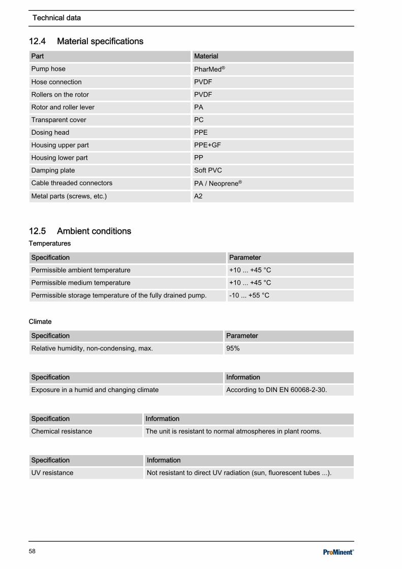
12.4 Material specificationsPart Material
Pump hose PharMed®
Hose connection PVDF
Rollers on the rotor PVDF
Rotor and roller lever PA
Transparent cover PC
Dosing head PPE
Housing upper part PPE+GF
Housing lower part PP
Damping plate Soft PVC
Cable threaded connectors PA / Neoprene®
Metal parts (screws, etc.) A2
12.5 Ambient conditions
Specification Parameter
Permissible ambient temperature +10 ... +45 °C
Permissible medium temperature +10 ... +45 °C
Permissible storage temperature of the fully drained pump. -10 ... +55 °C
Specification Parameter
Relative humidity, non-condensing, max. 95%
Specification Information
Exposure in a humid and changing climate According to DIN EN 60068-2-30.
Specification Information
Chemical resistance The unit is resistant to normal atmospheres in plant rooms.
Specification Information
UV resistance Not resistant to direct UV radiation (sun, fluorescent tubes ...).
Temperatures
Climate
Technical data
58

12.6 Degree of protection and safety requirements
Specification Information
Protection against contact and moisture IP 65 according to DIN EN 60529.
Specification Information
Protection class 1 - according to DIN EN 60335-1 (protective conductor connectionrequired).
12.7 Electrical data
Specification Parameter
Connection voltage 100…240 Volt
Mains frequency 50/60 Hz
Power consumption 0.4 ... 0.2 A
Power consumption approx. 24 watts
Switching-on duration 100%
Fuse value* 1.0 slow blow
* Type Schurter® series SPT
A unit fuse (short-circuit protection) is fitted.
Type: Micro-step control (16 micro-steps per step)
Specification Parameter
Switching-on duration 100%
Nominal voltage 24 Volt
Max. phase current at motor start-up* 1.9 A
Max. phase current in continuous operation* 1.7 A
* regulated
External inputs:Supply for external units: Rating +5 V / 50 mA, short circuit-proof
Input Specification Parameter
Contact input Input resistance: 15 kΩ against +5 V
Max. input frequency: 10 Hz
0 ... 20 mA input Input resistance: 120 Ω against GND
Degree of protection
Safety requirements
Overall unit
Control of the step motor
Inputs
Technical data
59

Input Specification Parameter
Filter time constants: 1 second
0 ... 10 V input Input resistance: 13 kΩ against +5 V
Filter time constants: 1 second
Tab. 14: Pause input:Input Specification Value
Contact input Input resistance: 15 kΩ against +5 V
Max. input frequency: 10 Hz
Tab. 15: ‘AUX_1’ input:Input Specification Value
Contact input Input resistance: 1 kΩ against +5 V
Max. input frequency: 10 Hz
Tab. 16: Level input deactivation:Input Specification Value
Contact input Input resistance: 15 kΩ against +5 V
Filter time constants: 2 seconds
0 ... 20 mA input Input resistance: 120 Ω against GND
Filter time constants: 1 second
Tab. 17: Level input prewarning / ‘AUX_2’ :Input Specification Value
Contact input Input resistance: 15 kΩ against +5 V
Max. input frequency: 10 Hz
Tab. 18: Alarm relay:Input Specification Value
Output relay output Type of contact: N/O contact, interference-suppressed withvaristor
Load capacity: 250 VAC, 3 A, 700 VA
Contact lifespan: > 105 switching operations in accordance withEN 60730-1
12.8 Sound pressure level< 60 dB (A) at maximum back pressure (water) according to DINEN 3743-1.
Outputs
Sound pressure level
Technical data
60

13 Ordering information for spare parts/accessoriesOrdering address for spare parts and accessories: The currentaddress for ordering spare parts and accessories can be found onthe manufacturer's homepage www.prominent.com.
A2561
Fig. 23: Pump hose for DF4a
Tab. 19: Pump hoses for DF4aType Material Colour Order no.
04004 PharMed® black 1034997
04015 PharMed® blue 1030722
03060 PharMed® orange 1030723
02120 PharMed® white 1030774
Tab. 20: Other partsProduct Order no.
Assembly material, complete, 3P Universal 815308
Mains cable Ordered using the identity code (“Cable andplug”)
Lip-seal metering valve PCB and 10 metre PE meteringline
Ordered using the identity code (“Accessories”)
Ordering information for spare parts/accessories
61

14 Declaration of Conformity for MachineryIn accordance with DIRECTIVE 2006/42/EC OF THE EUROPEANPARLIAMENT AND OF THE COUNCIL, Appendix I, BASICHEALTH AND SAFETY REQUIREMENTS, section 1.7.4.2. C.We,n ProMinent GmbHn Im Schuhmachergewann 5 - 11n D - 69123 Heidelberg, Germany,hereby declare that the product specified in the following, complieswith the relevant basic health and safety requirements of the ECDirective, on the basis of its functional concept and design and inthe version distributed by us.Any modification to the product not approved by us will invalidatethis declaration.
Tab. 21: Extract from the EC Declaration of ConformityDesignation of the product: Peristaltic pump, DULCOflex
Product type: DF4a
Serial number: see nameplate on the device
Relevant EC directives: Machinery Directive (2006/42/EC)Compliance with the protection targets of the Low Voltage Directiveaccording to Appendix I, No. 1.5.1 of the Machinery Directive(2006/42/EC)RoHS Directive (2011/65/EU)EMC Directive (2014/30/EU)
Harmonised standards applied,in particular:
EN ISO 12100: 2010EN 809: 1998 + A1: 2009 + AC: 2010EN 61010-1: 2010EN 50581: 2012EN 61000-6-2: 2005 + AC: 2005EN 61000-6-3: 2007 + A1: 2011 + AC: 2012
Date: 20.04.2016
You can download the Declaration of Conformity at www.promi‐nent.com.
Declaration of Conformity for Machinery
62

15 Overview of setting parameters
Parameter Meaning Setting range Factory setting
‘DOS’ Capacity 7.5 ml/h* ... 99.80 l/h* 0.30 l/h
AUX_1 / AUX_2 Manual capacity change 7.5 ml/h* ... 1.50 l/h* 0.75 l/h / 1.25 l/h
MODE Operating mode ‘MANUAL’ ,‘ANALOG’ ,‘CONTACT’
‘MANUAL’
‘ANALOG MODE’ Analogue operating mode 0 ... 20 mA,4 ... 20 mA,0 ... 10 V
0 ... 20 mA
‘ANALOG MIN.’ Capacity at 0/4 mA or 0 V 0.0 l/h ... 1.50 l/h* 0.75 l/h
‘ANALOG MAX.’ Capacity at 20 mA or 10 V 0.0 l/h ... 1.50 l/h* 1.25 l/h*
‘PAUSE’ Pause input ‘NORM.OPEN’ ,‘NORM.CLOSE’
(dependent on identitycode)
‘LIMIT MODE’ Level operating mode ‘LEVEL 1 ST.’ , ‘LEVEL2 ST.’
‘LEVEL 2 ST.’
‘LIMIT ERROR’ Level shut-off ‘NORM.OPEN’ ,‘NORM.CLOSE’
(dependent on identitycode)
‘LIMIT WARN’ Level warning ‘NORM.OPEN’ ,‘NORM.CLOSE’
(dependent on identitycode)
‘RELAY’ Relay output ‘NORM.OPEN’ ,‘NORM.CLOSE’
(dependent on identitycode)
‘RELAY-LEVEL’ Relay message level ‘LEVEL 1’ ,‘ LEVEL 2’ ,‘LEVEL 3’
‘LEVEL 1’
‘STARTCONTROL’ Start-up behaviour of thestep motor
‘ON’ / ‘OFF’ ‘OFF’
‘TUBE LIMIT’ Hose replacement,warning time
0 ... 20000 h 5000 h
‘LCD-CONTRAST’ Display contrast 0 ... 100% 38%
‘RELAY-MODE’ Relay operating mode ‘ALARM RELAY’ ,‘MV RELAY’
ALARM RELAY
‘ENTER CODE’ Enter access code 0000 ... 9999 1111
‘ACCESS LEVEL’ Level access protection NONE,LOCK MENU,LOCK ALL
NONE
‘APPLICATION’ Application CHEM-PUMP,FLOC DOSING,ACTIVE CARBON,
(dependent on identitycode)
* for the 1.5 l/h pump
Application as chemical pump
Overview of setting parameters
63

Parameter Meaning Setting range Factory setting
‘TUBE TYPE’ Hose dimensions 0.5 l/h,1.5 l/h,6.0 l/h,12.0 l/h
(dependent on identitycode)
‘CONCENTRAT.’ Concentration 0.01 ppm ... 9999 ppm 40.0 ppm
‘MASS PERCENT’ Mass percent 0.1 ... 100.0% 100.0%
‘DENSITY’ Density 0.50 ... 2.00 kg/l 1.0 kg/l
‘FACTOR’ Pulse interval factor 0.001 ... 1000 (l/p) 1.000 (l/p)
‘VOLUME /PULS’ Metering volume per con‐tact
0.001... 9999 ml/p 0.040 ml/p
‘MEMORY’ Contact memory OFF, ON OFF
‘CONC.-MODE’ Concentration mode OFF, ON OFF
‘PAUSE-DELAY’ Delay period after pause 0 s ... 9:59 m 0 s
* for the 1.5 l/h pump
Overview of setting parameters
64

Parameter Meaning Setting range Factory setting
‘CONC’ Metering concentration 0.01 ml/m³ ... 99.9 ml/m³ 1.5 ml/m³
‘FLOW’ Circulation capacity 0(1) m³/h – 999 m³/h 200 m³/h
‘DOS’ Capacity 7.5 ml/h* ... 99.80 l/h* 0.30 l/h
‘MANUAL’ Manual capacity 0.5% ... 100.0% 20%*
‘AUX_1 / AUX_2’ Manual capacity change 1% ... 150% 50% / 100%
‘MODE’ Operating mode MANUAL,ANALOG,CONTACT
MANUAL
‘ANALOG MODE’ Analogue operating mode 0 ... 20 mA,4 ... 20 mA,0 ... 10 V
0-20 mA
‘ANALOG MIN.’ Minimum circulationcapacity
0 m³/h‘(ANALOG_MAX.-1)’
0 m³/h
‘ANALOG MAX.’ Maximum circulationcapacity
‘(ANALOG_MIN+1’ ) 999m³/h
500 m³/h
‘PAUSE’ Pause input ‘NORM.OPEN’ ,‘NORM.CLOSE’
(dependent on identitycode)
‘LIMIT MODE’ Level operating mode ‘LEVEL 1 ST.’ , ‘ LEVEL2 ST.’
‘LEVEL 2 ST.’
‘LIMIT ERROR’ Level shut-off ‘NORM.OPEN’ ,‘NORM.CLOSE’
(dependent on identitycode)
‘LIMIT WARN’ Level warning ‘NORM.OPEN’ ,‘NORM.CLOSE’
(dependent on identitycode)
‘RELAY’ Relay output ‘NORM.OPEN’ ,‘NORM.CLOSE’
(dependent on identitycode)
‘RELAY-LEVEL’ Relay alert level ‘LEVEL 1’ ,‘LEVEL 2’ ,‘ LEVEL 3’
‘LEVEL 1’
‘STARTCONTROL’ Start-up behaviour of thestep motor
ON / OFF ‘OFF’
‘TUBE LIMIT’ Hose replacement, warningtime
0 ... 20000 h 5000 h
‘LCD-CONTRAST’ Display, contrast 0 ... 100% 38%
‘RELAY-MODE’ Relay operating mode ‘ALARM RELAY,’‘MV RELAY ’
ALARM RELAY
‘REVERSE-TIME’ Reverse run time (anti-clockwise)
0 s ... 30 m 6 s
‘REV.-INTERVAL’ Reverse interval time 0 h ... 2399 h 0 h
‘REVERSE FREQ’ Reverse speed 1% ... 100.0% 100%
* for the 1.5 l/h pump
Application as flocculant pump andactive carbon pump
Overview of setting parameters
65

Parameter Meaning Setting range Factory setting
‘REV.RUN COUNT’ Service interval counter 0 ... 32767 0
‘REV. TESTMODE’ Test operation for reversemode
OFF, ON OFF
‘ENTER CODE’ Enter access code 0000 ... 9999 1111
‘ACCESS LEVEL’ Level access protection NONE,LOCK MENU,LOCK ALL
NONE
‘APPLICATION’ Application CHEM-PUMP,FLOC DOSING,ACTIVE CARBON,
(dependent on identitycode)
‘TUBE TYPE’ Hose dimensions 0.5 l/h,1.5 l/h,6.0 l/h,12.0 l/h
(dependent on identitycode)
‘CONCENTRAT.’ Concentration 0.01 ppm ... 9999 ppm 40.0 ppm
‘MASS PERCENT’ Mass percent 0.1 ... 100.0% 100.0%
‘DENSITY’ Density 0.50 ... 2.00 kg/l 1.0 kg/l
‘FACTOR’ Pulse interval factor 0.001 ... 1000 (l/p) 1.000 (l/p)
‘VOLUME /PULS’ Metering volume per con‐tact
0.001 ... 9999 ml/p 0.040 ml/p
‘MEMORY’ Contact memory OFF, ON OFF
‘CONC.-MODE’ Concentration mode OFF, ON OFF
‘PAUSE-DELAY’ Delay period after pause 0 s ... 9:59 m 0 s
* for the 1.5 l/h pump
Overview of setting parameters
66

16 IndexAAccess code . . . . . . . . . . . . . . . . . . . . . . . . . . . . 47Access level . . . . . . . . . . . . . . . . . . . . . . . . . . . . 46ACCESS LEVEL . . . . . . . . . . . . . . . . . . . . . . . . . 46Accessories . . . . . . . . . . . . . . . . . . . . . . . . . . . . . 61Action, step by step . . . . . . . . . . . . . . . . . . . . . . . . 2Active carbon pump . . . . . . . . . . . . . . . . . . . . . . 46Ambient conditions . . . . . . . . . . . . . . . . . . . . . . . 58ANALOG . . . . . . . . . . . . . . . . . . . . . . . . . . . . 33, 38APPLICATION . . . . . . . . . . . . . . . . . . . . . . . . . . 46Applied harmonised standards . . . . . . . . . . . . . . 62Assembly . . . . . . . . . . . . . . . . . . . . . . . . . . . . . . 16Automatic backflushing . . . . . . . . . . . . . . . . . . . . 44AUX . . . . . . . . . . . . . . . . . . . . . . . . . . . . . . . . . . 42AUX_1 . . . . . . . . . . . . . . . . . . . . . . . . . . . . . . . . . 23AUX_2 . . . . . . . . . . . . . . . . . . . . . . . . . . . . . . . . . 23
BBackflushes . . . . . . . . . . . . . . . . . . . . . . . . . . . . . 45Backflushing interval . . . . . . . . . . . . . . . . . . . . . . 44Backflushing parameters . . . . . . . . . . . . . . . . . . . 44
CCalibration . . . . . . . . . . . . . . . . . . . . . . . . . . . . . . 48CALIBRATION . . . . . . . . . . . . . . . . . . . . . . . . . . 48Capacity . . . . . . . . . . . . . . . . . . . . . . . . . . . . 33, 34Capacity change . . . . . . . . . . . . . . . . . . . . . . . . . 23CHANGE CODE . . . . . . . . . . . . . . . . . . . . . . . . . 47CHANGE TUBE . . . . . . . . . . . . . . . . . . . . . . . . . 45Chemical pump . . . . . . . . . . . . . . . . . . . . . . . . . . 46Circulation capacity . . . . . . . . . . . . . . . . . . . . . . . 33CLEAR COUNTER . . . . . . . . . . . . . . . . . . . . . . . 44Climate . . . . . . . . . . . . . . . . . . . . . . . . . . . . . . . . 58Commissioning . . . . . . . . . . . . . . . . . . . . . . . . . . 26CONC . . . . . . . . . . . . . . . . . . . . . . . . . . . . . . . . . 33CONCENTRAT . . . . . . . . . . . . . . . . . . . . . . . . . . 38Concentration . . . . . . . . . . . . . . . . . . . . . . . . . . . 38CONFIG . . . . . . . . . . . . . . . . . . . . . . . . . . . . . . . 42Construction . . . . . . . . . . . . . . . . . . . . . . . . . . . . . 6CONTACT . . . . . . . . . . . . . . . . . . . . . . . . . . . . . . 34Continuous displays . . . . . . . . . . . . . . . . . . . . . . 31Control elements . . . . . . . . . . . . . . . . . . . . . . . . . . 7Control keys . . . . . . . . . . . . . . . . . . . . . . . . . . . . 29Control unit . . . . . . . . . . . . . . . . . . . . . . . . . . . . . 28Counter . . . . . . . . . . . . . . . . . . . . . . . . . . . . . . . . 44
COUNTER . . . . . . . . . . . . . . . . . . . . . . . . . . . . . 44
DDate, nameplate . . . . . . . . . . . . . . . . . . . . . . . . . . 6Decommissioning . . . . . . . . . . . . . . . . . . . . . . . . 55Decontamination declaration . . . . . . . . . . . . . . . . 56Degree of protection . . . . . . . . . . . . . . . . . . . . . . 59Designation of the product . . . . . . . . . . . . . . . . . 62Dimensional drawing . . . . . . . . . . . . . . . . . . . . . . 17Dimensions and weights . . . . . . . . . . . . . . . . . . . 57Disposal . . . . . . . . . . . . . . . . . . . . . . . . . . . . . . . 56DOS . . . . . . . . . . . . . . . . . . . . . . . . . . . . . . . . . . 33
EElectrical data . . . . . . . . . . . . . . . . . . . . . . . . . . . 59Emergency . . . . . . . . . . . . . . . . . . . . . . . . . . . . . 13Error messages . . . . . . . . . . . . . . . . . . . . . . . . . . 53
FFACTOR . . . . . . . . . . . . . . . . . . . . . . . . . . . . 34, 41Faults . . . . . . . . . . . . . . . . . . . . . . . . . . . . . . . . . 53Final concentration . . . . . . . . . . . . . . . . . . . . . . . 33Flocculant pump . . . . . . . . . . . . . . . . . . . . . . . . . 46FLOW . . . . . . . . . . . . . . . . . . . . . . . . . . . . . . . . . 33Frequency operation . . . . . . . . . . . . . . . . . . . . . . 39Functional description . . . . . . . . . . . . . . . . . . . . . . 6
GGeneral non-discriminatory approach . . . . . . . . . . 2
HHardware version . . . . . . . . . . . . . . . . . . . . . . . . 45Hose type . . . . . . . . . . . . . . . . . . . . . . . . . . . . . . 46
IIdentity code . . . . . . . . . . . . . . . . . . . . . . . . . . . . 45INFO . . . . . . . . . . . . . . . . . . . . . . . . . . . . . . . . . . 45Information in the event of an emergency . . . . . . 13Inputs, electrical . . . . . . . . . . . . . . . . . . . . . . . . . 59Installation . . . . . . . . . . . . . . . . . . . . . . . . . . . . . . 16Intended use . . . . . . . . . . . . . . . . . . . . . . . . . . . . 14
LLCD-CONTRAST . . . . . . . . . . . . . . . . . . . . . . . . 45LED . . . . . . . . . . . . . . . . . . . . . . . . . . . . . . . . 29, 39Level . . . . . . . . . . . . . . . . . . . . . . . . . . . . 24, 43, 59LEVEL relay . . . . . . . . . . . . . . . . . . . . . . . . . . . . 43
Index
67

LIMIT . . . . . . . . . . . . . . . . . . . . . . . . . . . . . . . . . . 43Links to elements or sections of these instruc‐tions or other applicable documents . . . . . . . . . . . 2
MMaintenance intervals . . . . . . . . . . . . . . . . . . . . . 50MANUAL . . . . . . . . . . . . . . . . . . . . . . . . . . . . . . . 33Manual backflushing . . . . . . . . . . . . . . . . . . . . . . 44Material specifications . . . . . . . . . . . . . . . . . . . . . 58Memory . . . . . . . . . . . . . . . . . . . . . . . . . . . . . . . . 39MEMORY . . . . . . . . . . . . . . . . . . . . . . . . . . . 34, 39Metering concentration . . . . . . . . . . . . . . . . . . . . 33Metering volume per contact . . . . . . . . . . . . . . . . 34MODE . . . . . . . . . . . . . . . . . . . . . . . . . . . . . . . . . 38More symbols . . . . . . . . . . . . . . . . . . . . . . . . . . . . 2
NNode ID . . . . . . . . . . . . . . . . . . . . . . . . . . . . . . . . 45Non-discriminatory approach . . . . . . . . . . . . . . . . 2
OOperating hours . . . . . . . . . . . . . . . . . . . . . . . . . 45Operating menu . . . . . . . . . . . . . . . . . . . . . . . . . 34Operating menu structure . . . . . . . . . . . . . . . . . . 34Operating mode . . . . . . . . . . . . . . . . . . . . . . . . . 38Operation . . . . . . . . . . . . . . . . . . . . . . . . . . . . . . 49Ordering information . . . . . . . . . . . . . . . . . . . . . . 61Outputs, electrical . . . . . . . . . . . . . . . . . . . . . . . . 60Overview of equipment . . . . . . . . . . . . . . . . . . . . . 7
PParameter . . . . . . . . . . . . . . . . . . . . . . . . . . . . . . 38Parked position . . . . . . . . . . . . . . . . . . . . . . . . . . 19Pause . . . . . . . . . . . . . . . . . . . . . . . . . . . . . . . . . 59PAUSE . . . . . . . . . . . . . . . . . . . . . . . . . . . . . . . . 43Performance data . . . . . . . . . . . . . . . . . . . . . . . . 57Precision . . . . . . . . . . . . . . . . . . . . . . . . . . . . . . . 57Priming . . . . . . . . . . . . . . . . . . . . . . . . . . . . . . . . 49Protective equipment . . . . . . . . . . . . . . . . . . . . . 13Pulse interval . . . . . . . . . . . . . . . . . . . . . . . . . . . 34Pump hose . . . . . . . . . . . . . . . . . . . . . . . . . . . . . 45
RRecycling . . . . . . . . . . . . . . . . . . . . . . . . . . . . . . 15Regulations governing the disposal of usedparts . . . . . . . . . . . . . . . . . . . . . . . . . . . . . . . . . . 56Relay . . . . . . . . . . . . . . . . . . . . . . . . . . . . . . . 43, 60RELAY . . . . . . . . . . . . . . . . . . . . . . . . . . . . . . . . 43
Relevant EC directives: . . . . . . . . . . . . . . . . . . . . 62Replacing the feed chemical storage tank . . . . . . 49Replacing the pump hose . . . . . . . . . . . . . . . . . . 51REV.-INTERVAL . . . . . . . . . . . . . . . . . . . . . . . . . 44REVERSE . . . . . . . . . . . . . . . . . . . . . . . . . . . . . . 44REVERSE FREQ. . . . . . . . . . . . . . . . . . . . . . . . . 45REVERSE-TIME . . . . . . . . . . . . . . . . . . . . . . . . . 44
SSafety chapter . . . . . . . . . . . . . . . . . . . . . . . . . . . 10Safety requirements . . . . . . . . . . . . . . . . . . . . . . 59SECURITY . . . . . . . . . . . . . . . . . . . . . . . . . . . . . 46Security-relevant settings . . . . . . . . . . . . . . . . . . 46Serial number . . . . . . . . . . . . . . . . . . . . . . . . . . . 62SERVICE . . . . . . . . . . . . . . . . . . . . . . . . . . . . . . 44SET . . . . . . . . . . . . . . . . . . . . . . . . . . . . . . . . . . . 38Setting . . . . . . . . . . . . . . . . . . . . . . . . . . . . . . . . . 28Setting parameters, overview . . . . . . . . . . . . . . . 63Software version . . . . . . . . . . . . . . . . . . . . . . . . . 45Sound pressure level . . . . . . . . . . . . . . . . . . . . . 60Start-up behaviour . . . . . . . . . . . . . . . . . . . . . . . . 43STARTCONTROL . . . . . . . . . . . . . . . . . . . . . . . . 43Storage . . . . . . . . . . . . . . . . . . . . . . . . . . . . . . . . 15Symbols . . . . . . . . . . . . . . . . . . . . . . . . . . . . . . . 28System information . . . . . . . . . . . . . . . . . . . . . . . 45
TTechnical data . . . . . . . . . . . . . . . . . . . . . . . . . . . 57Temperature . . . . . . . . . . . . . . . . . . . . . . . . . . . . 45Temperatures . . . . . . . . . . . . . . . . . . . . . . . . . . . 58Transport . . . . . . . . . . . . . . . . . . . . . . . . . . . . . . 15Troubleshooting . . . . . . . . . . . . . . . . . . . . . . . . . 53TUBE TYPE . . . . . . . . . . . . . . . . . . . . . . . . . . . . 46
UUser qualification . . . . . . . . . . . . . . . . . . . . . . . . . 12
VVOLUM . . . . . . . . . . . . . . . . . . . . . . . . . . . . . . . . 34
WWarning information . . . . . . . . . . . . . . . . . . . . . . 10Warnings . . . . . . . . . . . . . . . . . . . . . . . . . . . . . . . 53Wiring diagram . . . . . . . . . . . . . . . . . . . . . . . . . . 23
Index
68

69

70

71

986513, 3, en_GB
© 2018
ProMinent GmbHIm Schuhmachergewann 5 - 1169123 Heidelberg, GermanyGermanyTelephone: +49 6221 842-0Fax: +49 6221 842-419Email: [email protected]: www.prominent.com