petrol filling robot · pdf file · 2017-09-062.4 stepper motor controlling of...
TRANSCRIPT

2012/2013
Petrol Filling Robot
Prepared by:
Mohammed Zohud, Mais Mansour, Mustafa Abd_Allah, Hasan
Mohammed
Supervisor:
Dr.Nidal Farahat
A Graduation Project Submitted in Partial Fulfillment of the
Requirements of
Degree of B.Sc. In Mechatronics Engineering
Mechatronics Engineering Department
Engineering Faculty
An-Najah National University

1
Table of Contents
Abstract: ................................................................................................................................................. 3
List of figures1: ...................................................................................................................................... 5
1.1 Introduction ...................................................................................................................................... 6
1.2 Wheels design .................................................................................................................................. 6
1.2 Selection of horizontal plate and cartages material and design ....................................................... 8
1.3 Selection of screws and split nuts: ................................................................................................. 10
1.4 Selection of bearings, gears, and belts ........................................................................................... 11
1.5 Pulleys attachment to the shafts of the steppers: ........................................................................... 13
1.6 Robot workspace ............................................................................................................................ 15
List of figures2: .................................................................................................................................... 17
List of tables2:...................................................................................................................................... 18
2.1 Introduction .................................................................................................................................... 19
2.2 Motors selection ............................................................................................................................. 19
2.3 DC Motor controlling of direction and speed ................................................................................ 20
2.3.1 DC Motors - polarity/direction and PWM/speed .................................................................... 20
2.4 Stepper motor controlling of direction and speed .......................................................................... 25
2.5 Limit switches: ............................................................................................................................... 29
2.6 Analogue distance sensor ............................................................................................................... 31
2.7 Digital camera ................................................................................................................................ 34
List of tables3:...................................................................................................................................... 38
3.1 Image processing ........................................................................................................................... 39
3.1.1 Introduction ............................................................................................................................. 39
3.1.2 Definition of image and get the (X,Y) coordinate .................................................................. 39
3.1.3 Camera Calibration ................................................................................................................. 44
3.2 Calibration of stepper and DC motor with clock of the Arduino .................................................. 45
3.3 Arduino processor connections ...................................................................................................... 48
3.3.1 Introduction ............................................................................................................................. 48
3.3.2 Arduino wiring with sensors and actuators ............................................................................. 51
3.4 The working sequence analyses of the system .............................................................................. 53
3.4.1 The sequence of operation....................................................................................................... 53
3.4.2 Safety approach ....................................................................................................................... 54
3.5 Flow chart diagram ........................................................................................................................ 55
3.6 Applying code: ............................................................................................................................... 59

2
References: ........................................................................................................................................... 66
Appendices:.......................................................................................................................................... 68
1.1 OpenCV ...................................................................................................................................... 68
1.2 Work plan of project: Arrange of problems and points which we plan to do by the time: ........ 70

3
Abstract:
As we see nowadays there are so much fuel filling stations spread in all over the world. By using
petrol filling robot in these stations we can minimize the time, effort, and cost. The methodology relies
mainly to design robot which can take image of the car to track the fuel tank slot. Then robot will
reach to the tank slot and enter its gun inside it in order to fill fuel in tank. The study recommended
using VISA card automated with robot and a gripper for the robot, to enable opening the cover of the
tank and closes it, so we can use that alone without any worker.

4

5
List of figures: Figure 1. 1 Final robot design ................................................................................................................ 6
Figure 1. 2 a driving wheel type sliding over the aluminum rod track. ................................................. 7
Figure 1. 3 The driving shafts each one has a pulley, the tall one is for cartage 1 and the short one is
for cartage 2. .......................................................................................................................................... 8
Figure 1. 4 The horizontal plate ............................................................................................................. 8
Figure 1. 5 cartage 1 parts, a) the lower track base, b) the upper track base and c) the housing of
bases. ...................................................................................................................................................... 9
Figure 1. 6 Upper and lower bases of cartage 2. .................................................................................... 9
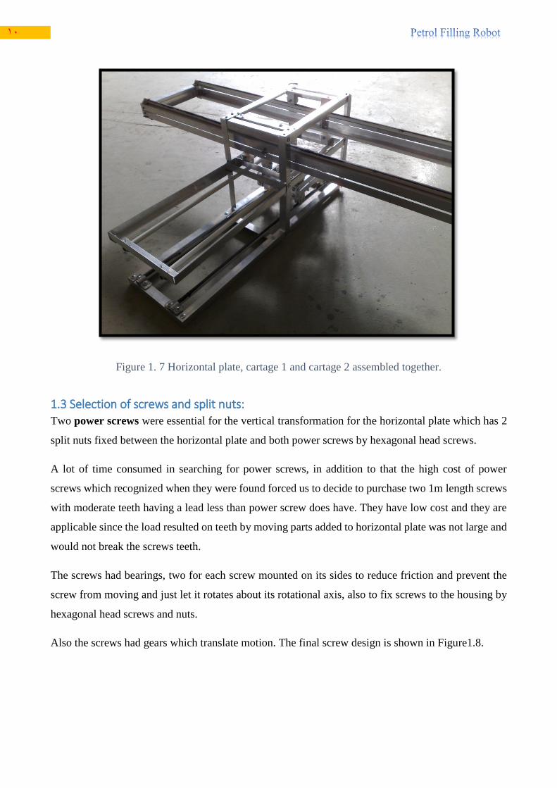
Figure 1. 7 Horizontal plate, cartage 1 and cartage 2 assembled together. .......................................... 10
Figure 1. 8 Two screws each one has a split nut, 2 ball bearings and two gears. ................................ 11
Figure 1. 9 Ball bearing. ...................................................................................................................... 11
Figure 1. 10 A gear on top of the screw acquires motion from the driving gear through a chain
between them. ...................................................................................................................................... 12
Figure 1. 11 Transmission of motion between gears at the screws bottoms through a chain attached
between them. ...................................................................................................................................... 12
Figure 1. 12 Belt used to rotate the cartages ........................................................................................ 13
Figure 1. 13 Adhesive making way. .................................................................................................... 13
Figure 1. 14 Adhesive filled between motors shafts and their pulleys. ............................................... 14
Figure 1. 15 A stepper mounted to cartage 1. ...................................................................................... 14
Figure 1. 16 Robot workspace ............................................................................................................. 15
Figure 1. 17 Robot workspace ............................................................................................................. 15
Figure 1. 18 2-megapixel web camera (2013) ..................................................................................... 34

6
Ch1 Mechanical Design
1.1 Introduction In this chapter we will show the final form of the mechanical design of the robot and its main parts
and will discuss the problems we faced during fixing them together in order to achieve the proper,
desired and soft movement, which is the main wish for a mechanical design.
In addition to that, we will show how the assembly ways for several parts were used (in details) and
of course the selections for every component used.
The resulted robot was a 3 degree of freedom robot (serial robot) with prismatic joints since wheels
and power screw where used in linear movement. The final mechanical design of the robot is shown
in Figure 1.1:
1.2 Wheels design Wheels were the first thing proper for design since the other components and parts design depends on
wheels size basically and its desired for the wheels to have a small size diameter and width to adjust
Figure 1. 1 Final robot design

7
the largest distance travelled in the three dimensions (workspace of the robot). They are needed to be
made from a plastic material (polyethylene) in order to have negligible weight since we are
recommended to have a large number of wheels (16 wheels).
Note that wheels must have a semicircular groove to make wheel itself capable to roll over a linear
rod which have a circular cross section.
Wheels were the first problem in mechanical design and the most dangerous since they waste a lot of
time to recognize either them available or not in markets. Unfortunately we did not find wheels that
have the desired design characteristics mentioned. So we decided to make wheels by our own hands
and purchase a polyethylene rod with 3 cm diameter and prepare a cutting tool which has semicircular
shape suitable for groove to be made and we made from the rod 16 wheel pieces using the Lathe
machine.
After we made wheels we drilled their centers and assembled it with its rotational screw and aluminum
cover with nuts. Figure 1.2 shows a driving wheel type capable to slide over an aluminum rod track.
Figure 1. 2 a driving wheel type sliding over the aluminum rod track.
Four wheels were driving ones and the rest were driven by them and each couple of driving wheels
were assembled by a rotating shaft (rod) that have a pulley at its center which attached to the stepper
motor by a belt. See Figure 1.3 which shows the rotating shafts for the driving wheels, one for cartage
1 and another shaft for cartage 2.

8
Figure 1. 3 The driving shafts each one has a pulley, the tall one is for cartage 1 and the short one is
for cartage 2.
1.2 Selection of horizontal plate and cartages material and design Horizontal plate was formed using 20*20 mm aluminum equal angle profiles, profiles were
assembled by screws in connection points between profiles using a drill, so the final horizontal plate
design was a rectangular shape that have 100 cm length, 25 cm width and 4 cm height. See Figure 1.4
which shows the horizontal plate from top view.
After that the four track rods were fixed on plate (two for each side) for moving wheels. Flat rubber
tapes were glued over track rods to force the wheels to move on the track without slipping.
Figure 1. 4 The horizontal plate
Cartage 1 and cartage 2 were formed in different measures and shapes, for each cartage, there were
eight wheels; two wheels were driven by the motor mounted on the cartage and six wheels were driven

9
by the driving wheels. The function of the six driven wheels was to keep cartage on the motion tracks
and to prevent cartage bend due to bending moments resulted, all wheels were fixed on the cartage
faces by screws using a drill. As shown in Figures 1.5 and 1.6, the cartage 1 and 2 parts are shown
separately, and Figure 1.7 shows cartage 1 and 2 assembled with the horizontal plate. For cartage 1,
the housing was 32 cm long, 20 cm wide and 30 cm hieght and the two bases were 66 cm long and 20
cm wide. Cartage 2 was 26 cm long and 16 cm wide.
Figure 1. 5 cartage 1 parts, a) the lower track base, b) the upper track base and c) the housing of
bases.
Figure 1. 6 Upper and lower bases of cartage 2.
11
Figure 1. 7 Horizontal plate, cartage 1 and cartage 2 assembled together.
1.3 Selection of screws and split nuts: Two power screws were essential for the vertical transformation for the horizontal plate which has 2
split nuts fixed between the horizontal plate and both power screws by hexagonal head screws.
A lot of time consumed in searching for power screws, in addition to that the high cost of power
screws which recognized when they were found forced us to decide to purchase two 1m length screws
with moderate teeth having a lead less than power screw does have. They have low cost and they are
applicable since the load resulted on teeth by moving parts added to horizontal plate was not large and
would not break the screws teeth.
The screws had bearings, two for each screw mounted on its sides to reduce friction and prevent the
screw from moving and just let it rotates about its rotational axis, also to fix screws to the housing by
hexagonal head screws and nuts.
Also the screws had gears which translate motion. The final screw design is shown in Figure1.8.

11
Figure 1. 8 Two screws each one has a split nut, 2 ball bearings and two gears.
1.4 Selection of bearings, gears, and belts Bearings are considered as 1 degree of freedom (1DOF) joints to which the rotating of the shaft
attached. And the rotational axis is vertical over its circular face and passes through its center. Bearings
main function was to reduce mechanical friction in order to make the horizontal plate move fast and
more efficiently.
We select a proper type of bearings (ball bearings) see Figure 1.9.
Figure 1. 9 Ball bearing.
Gears (chain rings) were selected to translate rotational motion of the DC motor into linear motion
of the horizontal plate through chains attached between each couple of chain rings. So the function
was that the DC motor start to rotate which cause the chain ring mounted on it (see Figure 1.10) starts
to rotate also. After that the rotational motion transmitted to the gear mounted on the top of a screw

12
and transmitted at the same time to the second screw through a chain attached between chain rings
fixed at screws bottoms shown in Figure 1.11. As a result, both of screws would rotate at the same
speed so the horizontal plate will move vertically up or down in efficient way without any inclination.
Figure 1. 10 A gear on top of the screw acquires motion from the driving gear through a chain
between them.
Figure 1. 11 Transmission of motion between gears at the screws bottoms through a chain attached
between them.
Belts were used to transmit rotational motion between stepper motors and their associated pulleys
attached at the drive shafts in the cartages. The traditional belt type was used which found in car

13
wheels since it can be made at any length and diameter, and its high flexibility, low maintenance and
durability distinguishes it from the other types of belts.
Figure 1. 12 Belt used to rotate the cartages
1.5 Pulleys attachment to the shafts of the steppers: Pulleys were fixed to their shafts using a strong adhesive called (POXIPOL) which was filled between
pulleys and their corresponding shafts; the adhesive was formed by mixing two deferent materials A
and B, the filling operation of the adhesive was quick due to fast manner in becoming hard (10
minutes).
Figure 1. 13 Adhesive making way.

14
Figure 1. 14 Adhesive filled between motors shafts and their pulleys.
After the adhesive has become hard the steppers were attached to the cartages.
Figure 1. 15 A stepper mounted to cartage 1.

15
1.6 Robot workspace The workspace of the robot is located within the Cartesian coordinate system, which has a values of
60, 45, and 60 cm as shown in Figure 1.16, the robot can reach any point located at its workspace.
Figure 1. 16 Robot workspace

16

17
List of figures:
Figure 2. 1 DC motor ........................................................................................................................... 19
Figure 2. 2 Bipolar stepper motor ........................................................................................................ 20
Figure 2. 3 Control the direction of rotation using relays .................................................................... 21
Figure 2. 4 Implemented circuit to control the direction of rotation for the DC motor ....................... 21
Figure 2. 5 PWM signal to control the speed of the DC motor ........................................................... 23
Figure 2. 6 Circuit diagram for opto-interrupter based encoder board. ............................................... 24
Figure 2. 7 Implemented encoder circuit ............................................................................................. 24
Figure 2. 8 Encoder circuit mounted on the DC motor ........................................................................ 25
Figure 2. 9 Produced voltage signal at the output of the encoder circuit. ............................................ 25
Figure 2 .11 Stepper motor control of direction of rotation ................................................................ 26
Figure 2. 11 Stepper drive circuit ........................................................................................................ 27
Figure 2. 12 Implemented stepper driver circuit .................................................................................. 28
Figure 2. 13 Stepper motor with drive circuit ...................................................................................... 28
Figure 2. 14 limiting the vertical motion two limit switches are used ................................................. 30
Figure 2. 15 limiting the perpendicular motion two limit switches are used ....................................... 30
Figure 2. 16 Lever operated limit switch ............................................................................................. 30
Figure 2. 17 Analogue distance sensor ................................................................................................ 31

18
List of tables: Table 2. 1 DC motor direction of rotation ........................................................................................... 22

19
Ch2 Motors
2.1 Introduction
Motors are essential parts in machines; they perform the mission of moving parts by convert the
electrical power to mechanical power, this conversion of power occurs by electromagnetic
phenomena, which states that the flowing current in the source circuit of the motor generates
magnetic field in the motor coils causing the motor shaft to moving in the form of torque(rotating),
which depends on the induced armature current, flux intensity, and other parameters related to motor
structure (number of turns, poles, connection type, etc…). Motors are classified in terms of various
objects including source type (AC/DC).
2.2 Motors selection
DC or AC motor types selection:
In our project we need to use motors for driving the mechanisms to satisfy the desired position of
the gun. It is better to use DC motors than AC motors, because the AC driving encoder for controlling
the motor more expensive and less accurate than DC motors types.
Our project includes three motors, one of them is a DC motor as shown in Figure 2.1, and the others
are stepper motors as shown in Figure 2.2. The DC motor found in Trucks windshield wipers is used
with encoder circuit for controlling the level of the gun in vertical direction, due to the relatively
large weight of robot components, and two stepper motors are chosen with theirs drive circuits for
monitoring the motion in perpendicular and horizontal directions, due to relatively small torque
needed to satisfy the motion.
Figure 2. 1 DC motor

21
Figure 2. 2 Bipolar stepper motor
DC motor is working on 60 watt DC input voltage (12 Vdc, 5 A) which can give a torque up to 5
N.m.
Stepper motor for cartage 1 is working on 24 watt DC input voltage (12 Vdc, 2 A) and for cartage 2
is working on 36 watt DC input voltage (12 Vdc, 3 A) and the produced torque equal to 2.6 N.m and
1.3 N.m respectively.
2.3 DC Motor controlling of direction and speed Usually microcontrollers are power supplied by low voltage power supply (DC voltage) and in the
meantime, it's required to control DC motors at the higher power consumption rate than controller can
provide, so not to burn out your microcontroller, you will need an intermediate device to convert
voltage levels and steer high current.
2.3.1 DC Motors - polarity/direction and PWM/speed
DC motors rotate direction depends on the polarity of its power supply (for example +/- forward, -/+
backward). So that by controlling the polarity of power supply applied to motor, we'll be able to
control rotation direction.
Simple way to make that is to use two relays with two transistors like in the Figure 2.3 bellow.
21
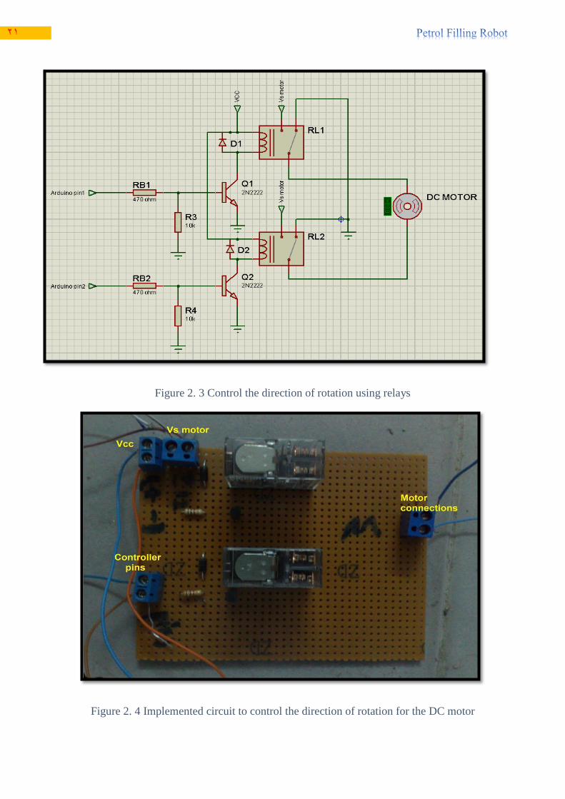
Figure 2. 3 Control the direction of rotation using relays
Figure 2. 4 Implemented circuit to control the direction of rotation for the DC motor

22
We use relays to control the direction of the DC motor instead of H-bridge, since the H-bridge circuit
contains many transistors which are extremely expensive (15 shekel for each one ) in comparison with
relays circuit (18 shekel for the whole circuit).
Protection in the circuit:
Relay 1 and Relay 2 provides a protection for output pins of the microcontroller (Arduino)
from a high DC supply voltage, which is required to operate the motor.
Protection diodes for relays coils: D1 and D2
Signal diodes are also used to protect transistors and ICs from the brief high voltage
produced when the relay coil is switched off. The above figure shows how a protection diode
is connected 'backwards' across the relay coil .The protection diodes allow the induced voltage
to drive a brief current through the coil (and diode), so the magnetic field dies away quickly
rather than instantly.
RB1 and RB2: resistors to limit the current at the base of the transistor.
R3 and R4: bleeder resistors to bleed off unwanted leakage through output pins of the
microcontroller.
The direction of rotation of the motor can be determined depending on the data received from Arduino
pins 1 and 2; the following table illustrates the direction of rotation of the motor.
Table 2. 1 DC motor direction of rotation
Arduino pin status Relay status Motor status
Pin no. 1 Pin no. 2 Rely no. 1 Relay no. 2
Off Off Off Off Off ( no rotation )
Off On Off On On ( anti-clock wise rotation)
On Off On Off On ( clock wise rotation)
On On On On Indeterminate

23
Speed control using PWM
Pulse Width Modulation, or PWM, is a technique for getting analog results with digital means. Digital
control is used to create a square wave, a signal switched between on and off. This on-off pattern can
simulate voltages in between full on (5 Volts) and off (0 Volts) by changing the portion of the time
the signal spends on versus the time that the signal spends off. The duration of "on time" is called the
pulse width. To get varying analog values, you change, or modulate, that pulse width. (2013)
The following diagram represents the PWM signal to control the speed of the motor
Figure 2. 5 PWM signal to control the speed of the DC motor
The duty cycle =
The frequency =
The Arduino's PWM frequency is about 500Hz, the time will be 2 milliseconds, and the duty cycle is
50 % (on half the time).
Position control of DC motor using encoder circuit
In this part we will show you a rotary encoder circuit, which consists of a disk with alternating opaque
and clear radial regions. In operation, a light source is positioned on one side of the disk, and a
photosensitive device, such as a photodiode is positioned on the other side of the disk. As the disk
rotates, the passage of the opaque and clear regions of the encoder disk alternately block and allow
light to impinge on the receiver, which produces corresponding voltage pulses. The rotational speed
of the encoder disk can be determined by counting pulses during a known time period. The angle of
rotation corresponds directly to the number of pulses, since the number of pulses per revolution is
constant.
Circuit Board – Optical Encoder Board

24
As we mentioned above, an optical encoder works by pairing some type of light emitting device with
a complementary light sensing device. Figure 2.6 below shows the circuit diagram for the optical
encoder system which it is used in our project.
Figure 2. 6 Circuit diagram for opto-interrupter based encoder board.
Description of operation:
If the current flows through the infrared diode on the emitter (E) side and passes through slots (holes)
in a disk, the photodiode is activated (ON) on the detector side and allows the current pass through.
If the light from the infrared diode is blocked, the photodiode on the detector side is deactivated (turn
off) and blocked the current from passing through.
Figure 2. 7 Implemented encoder circuit

25
The following diagram is taken from an Oscilloscope device which represents the signal produced at
the output of the encoder circuit when a shaft of a DC motor rotates.
The resolution of the incremental encoder depends on the number of slots in the disk. As shown from
the Figure 2.8 the disk has three slots, so that
Resolution =
* 100 % =
* 100% = 0.83 %
Figure 2. 9 Produced voltage signal at the output of the encoder circuit.
2.4 Stepper motor controlling of direction and speed
A stepper motor is a brushless, synchronous electric motor that converts digital pulses into mechanical
shaft rotation. Every revolution of the stepper motor is divided into a discrete number of steps, in
many cases 200 steps, and the motor must be sent a separate pulse for each step.
The stepper motor can only take one step at a time and each step is the same size. Since each pulse
causes the motor to rotate a precise angle. The motor's position can be controlled without any feedback
mechanism.
Figure 2. 8 Encoder circuit mounted on the DC motor

26
As the digital pulses increase in frequency, the step movement changes into continuous rotation, with
the speed of rotation directly proportional to the frequency of the pulses.
One of the ways used for controlling the direction of rotation is to use simple H-bridge circuit as
illustrated in Figure 2.9.
Figure 211 . Stepper motor control of direction of rotation
The circuit consists of four transistors for controlling the direction of stepper motor based on the
received voltage at the bases of transistors (Q1, Q2, Q3, and Q4)
Protection in the circuit:
D1, D2, D3, and D4: Protection diodes for relays: The protection diodes allow the induced
voltage to drive a brief current through the coil (and diode) so the magnetic field dies away
quickly rather than instantly.
RB1 and RB2, RB3, and RB4: resistors to limit the current at the base of the transistor.
R1, R2, R3, and R4: bleeder resistors to bleed off unwanted leakage through output pins of the
microcontroller.

27
Stepper motors widely controlled using special drivers instead of the simple way illustrated above;
the stepper drivers receive step (clock) and direction signals (reduces the required PINs used to
interface the circuit with the microcontroller) from the control system (Arduino) and convert them
into electrical signals to run the step motor; the conversion of step and direction are done by stepper
controller (L297) and dual full bridge driver (L298).
One pulse is required for every step of the motor shaft.
For controlling the direction and speed of stepper motor, the following technical circuit is used:
Figure 2. 11 Stepper drive circuit

28
Figure 2. 13 Stepper motor with drive circuit
Figure 2. 12 Implemented stepper driver circuit

29
The circuit function is to control the direction and the speed of the stepper by using two signal inputs
step (clock) and direction) instead of using four signal inputs; this will save the output pins of the
controller to be utilized in other tasks. (This will minimize the exerted Arduino pins.)
The direction of rotation is decided by taking a direction pin HIGH or LOW, and the speed is decided
by changing the duty cycle (frequency of the clock) of clock pin.
The circuit contains stepper controller (L297) and dual full bridge driver (L298). L297 is used to
transfer the received data from the microcontroller (Arduino) output pins into control signals (4 phase
drive signals) for L298 which actually drives the stepper motor.
The Stepper Motor Controller IC (L297) generates four phase drive signals for dual bridge diver
(L298) in microcontroller controlled applications. The motor can be driven in half step or in full step,
clock wise or counter clock wise, and in the required speed depending on applied logic on the stepper
controller pins.
The drive circuit able withstands high voltage and current due to the L298 is capable of driving up to
2A per coil.
2.5 Limit switches: They are small electrical switches which require physical contact and small operating force to close
the contact. When a circuit is closed, it allows the current to pass through to the device being powered.
Standardized limit switches are industrial control components manufactured with a variety of operator
types, including lever – operated, roller – operated, cam– operated.
In our filling robot there are six lever-operated limit switches to limit the movement in x, y, and z
directions. They work as an interrupt for the microcontroller inputs.
The limit switches locations in the robot are shown in the figures bellow.

31
The same for limiting the motion in horizontal axis, the limit switches are used
Figure 2. 14 limiting the vertical motion two limit switches are used
Figure 2. 15 limiting the perpendicular motion two limit switches are used
Figure 2. 16 Lever operated limit switch
31
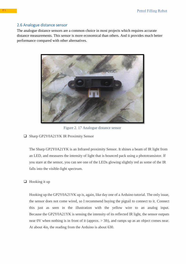
2.6 Analogue distance sensor The analogue distance sensors are a common choice in most projects which requires accurate
distance measurements. This sensor is more economical than others. And it provides much better
performance compared with other alternatives.
Sharp GP2Y0A21YK IR Proximity Sensor
The Sharp GP2Y0A21YK is an Infrared proximity Sensor. It shines a beam of IR light from
an LED, and measures the intensity of light that is bounced pack using a phototransistor. If
you stare at the sensor, you can see one of the LEDs glowing slightly red as some of the IR
falls into the visible-light spectrum.
Hooking it up
Hooking up the GP2Y0A21YK up is, again, like day one of a Arduino tutorial. The only issue,
the sensor does not come wired, so I recommend buying the pigtail to connect to it. Connect
this just as seen in the illustration with the yellow wire to an analog input.
Because the GP2Y0A21YK is sensing the intensity of its reflected IR light, the sensor outputs
near 0V when nothing is in front of it (approx. > 3ft), and ramps up as an object comes near.
At about 4in, the reading from the Arduino is about 630.
Figure 2. 17 Analogue distance sensor

32
What it is good/bad for
The GP2Y0A21YK is half the cost of the LV-EZ0, and incredibly simple to use, but there are
a few downfalls that make it unsuitable for sensing distance reliably. Unlike the LV-EZ0, its
output is not linear, so using this to read actual distance is difficult. Also because it is sensing
IR, I have seen the output value thrown off by a TV remote shined directly into it. And lastly,
once an object comes within 4in of the GP2Y0A21YK, the read values start to drop again
down to around 430 (reading from the arduino) when an object is in contact with the sensor.
(2013)
Calibration of sensor
Distance (cm) Voltage (v)
10 2.4
15 1.5
20 1.4
25 1.1
30 0.9
35 0.8
40 0.7
45 0.65
50 0.6
55 0.55
60 0.5
65 0.45
70 0.43
75 0.42
80 0.4

33
Figure 2. 18 output voltage versus distance
y = -0.00001x3 + 0.00248x2 - 0.14586x + 3.43696
y = 17.053x-0.861
R² = 0.9947
0
0.5
1
1.5
2
2.5
3
0 20 40 60 80 100
Vo
ltag
e (
V)
Distance (cm)
Voltage - Distance relationship
Series1
Poly. (Series1)
Power (Series1)

34
2.7 Digital camera A camera is a device that records images which can be stored directly, transmitted to another location,
or both. It is suitable type of camera for our project is waterproof camera as shown in figure 2.14.
Because it is 2-megapixel camera, resistant to low temperatures, and submerged conditions (12De5).
2-megapixel web camera (2013)
Figure 2. 19 connection of arduino with analogue distance sensor
Figure 2. 20 2-megapixel web camera

35

36

37
List of figures: Figure 3. 1 An image – an array or a matrix of pixels arranged in columns and rows. ....................... 39
Figure 3. 2 circle patern ....................................................................................................................... 44
Figure 3. 3 Distance vs clocks relationship for the stepper motor. ...................................................... 46
Figure 3. 4 Distance vs clocks relationship for DC motor. .................................................................. 48
Figure 3. 5 Arduino processor module ................................................................................................ 49
Figure 3. 6 Arduino schematic ............................................................................................................. 50
Figure 3. 7 Configuration system......................................................................................................... 51
Figure 3. 8 The real technical wiring between Arduino module and the peripherals. ......................... 53

38
List of tables: Table 3. 1 Comparison between programs available ........................................................................... 40
Table 3. 2 OpenCV documentations available in HTML .................................................................... 41
Table 3. 3 Structures for points, size, rectangles, and scalar tuples ..................................................... 43
Table 3. 4 OpenCV image types .......................................................................................................... 44
Table 3. 5 Data of distance and number of clocks for the stepper motor ............................................ 45
Table 3. 6 Data of distance and number of clock for DC motor .......................................................... 47
Table 3. 7 Summery about arduino ...................................................................................................... 49

39
Ch3 Control
3.1 Image processing
3.1.1 Introduction
Image processing is a method to convert an image into digital form and perform some operations on
it, in order to get an enhanced image or to extract some useful information from it. It is a type of signal
dispensation in which input is image, and output may be image or characteristics associated with that
image. Most image-processing techniques involve treating the image as a two-dimensional signal and
applying standard signal-processing techniques to it.
Image processing usually refers to digital image processing, but optical and analog image
processing also are possible.
In this case, digital computers are used to process the image. The image will be converted to digital
form using a scanner – digitizer and then process it. It is defined as the subjecting numerical
representations of objects to a series of operations in order to obtain a desired result.
The term digital image processing generally refers to processing of a two-dimensional picture by a
digital computer. In a broader context, it implies digital processing of any two-dimensional data. A
digital image is an array of real numbers represented by a finite number of bits. (2013)
3.1.2 Definition of image and get the (X,Y) coordinate
An image is an array, or a matrix, of square pixels (picture elements) arranged in columns and rows.
Figure 3. 1 An image – an array or a matrix of pixels
arranged in columns and rows.

41
What Is OpenCV?
OpenCV is an open source computer vision library available .The library is written in C and C++ and
runs under Linux, Windows and Mac OS X. There is active development on interfaces for Python,
Ruby, Matlab, and other languages. OpenCV was designed for computational efficiency and with a
strong focus on real-time applications. OpenCV is written in optimized C and C++.
OpenCV was designed to be portable. It was originally written to compile across Borland C++,
MSVC++, and the Intel compilers. This meant that the C and C++ code had to be fairly standard in
order to make cross-platform support easier.
What Is Computer Vision?
Computer vision is the transformation of data from a still or video camera into either a decision or a
new representation. All such transformations are done for achieving some particular goal.
This means you can take advantage of high speed implementations of functions commonly used in
Computer Vision/Image Processing. (2013)
The OpenCV library is obtained from Available on Sourceforge
http://sourceforge.net/projects/opencvlibrary
Table 3. 1 Comparison between programs available
MATLAB AForge OpenCV
Integrates computation,
visualization and programming
in a easy to use environment
C# library C/C++ library
Has huge array of provided
functions
Designed for developers and
researchers in the fields of
Computer Vision and Artificial
Intelligence
Open source
Great interface for displaying
and manipulating data while
debugging
Excellent documentation
Excellent for different
transforms and image
manipulation
Has Windows, Linux and Mac
versions
41
Excellent for math and
computation , algorithm
development, modeling,
simulation and prototyping
Easier than openCV and harder
than matlab
Has basic data structures for
matrix operation and image
processing
Excellent documentation Poor in matrix operations Code is highly optimized for
image processing
Very slow while processing
images
Can be used for real time
image processing
Fast and efficient
Bad documentation
Don’t handle errors
Hardly use for real time image
processing
Not fast and efficient as
openCV to process images
Can be recommended for any
complex real time image
processing
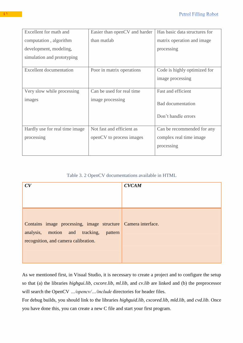
Table 3. 2 OpenCV documentations available in HTML
CV CVCAM
Contains image processing, image structure
analysis, motion and tracking, pattern
recognition, and camera calibration.
Camera interface.
As we mentioned first, in Visual Studio, it is necessary to create a project and to configure the setup
so that (a) the libraries highgui.lib, cxcore.lib, ml.lib, and cv.lib are linked and (b) the preprocessor
will search the OpenCV …/opencv/…/include directories for header files.
For debug builds, you should link to the libraries highguid.lib, cxcored.lib, mld.lib, and cvd.lib. Once
you have done this, you can create a new C file and start your first program.
42
These two headers are the most commonly used
1. highgui.h library is part of OpenCV, which could best be describes as a real time video capture
and object recognition library.
2. cv.h open cv library
Header files
#include <cv.h>
#include <cvaux.h>
#include <highgui.h>
#include <cxcore.h>
Functions used:
Function naming conventions
cvActionTargetMod(.....)
Action = the functionality (e.g. load, show)
Target = the target image area (e.g. contour, image)
Mod = optional modifiers (e.g. argument type)
Example:
cvLoadImage(...)
cvFitLine(...)
IplImage is the OpenCV construct with which you will deal the most. OpenCV uses this structure to
handle all kinds of images: single-channel, multichannel, integer-valued, floating-point-valued, et
cetera. We use the pointer that cvLoadImage() returns to manipulate the image and the image data
cvLoadImage() function is used to load the image, is a high-level routine that determines the file
format to be loaded based on the file name; it also automatically allocates the memory needed for the
image data structure. Note that cvLoadImage() can read a wide variety of image formats, including
BMP, DIB, JPEG, JPE, PNG, PBM, PGM, PPM,SR, RAS, and TIFF. (2013)
The simplest of these types is CvPoint. CvPoint is a simple structure with two integer members, x and
y. CvPoint has two siblings: CvPoint2D32f and CvPoint3D32f. The former has the same two members
x and y, which are both floating-point numbers. The latter also contains a third element, z.

43
CvSize is more like a cousin to CvPoint. Its members are width and height, which are both integers.
If you want floating-point numbers, use CvSize’s cousin CvSize2D32f.
CvRect is another child of CvPoint and CvSize; it contains four members: x, y, width, and height. (In
case you were worried, this child was adopted.)
Last but not least is CvScalar, which is a set of four double-precision numbers. When memory is not
an issue, CvScalar is often used to represent one, two, or three real numbers (in these cases, the
unneeded components are simply ignored). CvScalar has a single member val, which is a pointer to
an array containing the four double-precision floating-point numbers
Table 3. 3 Structures for points, size, rectangles, and scalar tuples
cvScalar() is a special case: it has three constructors. The first, called cvScalar(), takes one, two, three,
or four arguments and assigns those arguments to the corresponding elements of val[]. The second
constructor is cvRealScalar(); it takes one argument, which it assigns to val[0] while setting the other
entries to 0. The final variant iscvScalarAll(), which takes a single argument but sets all four elements
of val[] to that same argument. (2013)
Note that, there is no “vector” construct in OpenCV.
The routine that creates a new two-dimensional matrix has the following prototype:
cvMat* cvCreateMat ( int rows, int cols, int type ); . The easiest way to get at a member element of an
array is with the CV_MAT_ELEM() macro

44
Table 3. 4 OpenCV image types
3.1.3 Camera Calibration
Camera type is internet CAM 2 MPix. The function used for camera intrinsic and distortion
parameters:
cvCalibrateCamera2()
For circular tank slot, Use the OpenCV function Hough Circles to detect circles in an image. In the
circle case, we need three parameters to define a circle:
Where define the center position (green point) and is the radius, which allows us
to completely define a circle, as it can be seen below (2013)
Figure 3. 2 circle patern

45
3.2 Calibration of stepper and DC motor with clock of the Arduino We make calibration for the stepper and DC motor movement with the Arduino clock, to reach the
desired position which given in centimeters, by show the number of clock with distance move on the
computer. As we see in figure 3.3 and figure 3.4
Table 3. 5 Data of distance and number of clocks for the stepper motor
Distance(cm) # of clock
0 0
0.5 100
1 200
1.5 300
2 400
2.5 500
3 600
3.5 700
4 800
4.5 900
5 1000
5.5 1100
6 1200
6.5 1300
7 1400
7.5 1500
8 1600
8.5 1700
9 1800
9.5 1900

46
The yield equation for the relation between displacement and number of clock for the stepper motor
is:
One Clock= 200*distance.
10 2000
10.5 2100
Figure 3. 3 Distance vs clocks relationship for the stepper motor.
y = 200xR² = 1
0
500
1000
1500
2000
2500
0 2 4 6 8 10 12
# o
f cl
ock
distance(cm)
Distance Vs Clocks

47
Table 3. 6 Data of distance and number of clock for DC motor
Distance(cm) # of clock
0 0
0.5 250
1 500
1.5 750
2 1000
2.5 1250
3 1500
3.5 1750
4 2000
4.5 2250
5 2500
5.5 2750
6 3000
6.5 3250
7 3500
7.5 3750
8 4000
8.5 4250
9 4500
9.5 4750
10 5000

48
The yield equation for the relation between displacement and number of clock for the DC motor is:
One clock= 500*distance.
3.3 Arduino processor connections
3.3.1 Introduction
Arduino is an open-source electronics prototyping platform based on flexible, easy to use
hardware and software, Arduino can sense the environment by receiving input from a variety
of sensors and can affect it surroundings by controlling lights, motors and other actuators. Its
microcontroller is programmed by Arduino program language. As we see its module in
figure3.5.
y = 500xR ² =1
0
1000
2000
3000
4000
5000
6000
0 2 4 6 8 10 12
# o
f cl
ock
distance(cm)
Distance Vs Clocks
Figure 3. 4 Distance vs clocks relationship for DC motor.

49
Table 3. 7 Summery about arduino
Microcontroller ATmega328
Operating Voltage 5V
Input Voltage (recommended) 7-12V
Input Voltage (limits) 6-20V
Digital I/O Pins 14 (of which 6 provide PWM output)
Analog Input Pins 6
DC Current per I/O Pin 40 mA
DC Current for 3.3V Pin 50 mA
Flash Memory 32 KB (ATmega328) of which 0.5 KB used by bootloader
SRAM 2 KB (ATmega328)
EEPROM 1 KB (ATmega328)
Clock Speed 16 MHz
Figure 3. 5 Arduino processor module

51
Arduino processor has in its module a lot of chips and connections as we see in the Figure 3.6
Figure 3. 6 Arduino schematic

51
3.3.2 Arduino wiring with sensors and actuators
We attached some of the Arduino pins for the limit switches, analogue distance sensor, drivers of the
stepper motors, and H_bridge of the DC motor. As we see in the configuration system diagram in
figure 3.7
Figure 3. 7 Configuration system.

52
As we see in previous diagram the peripherals attached to the Arduino processor pins as following:
The driver1 attached to the digital output pin (0) which represent the clock pin, and to the
digital output pin (1) which represent the direction.
The driver2 attached to the digital output pin (2) which represent the clock pin, and to the
digital output pin (3) which represent the clock pin.
The H_bridge control pins attached to the output digital pin (4) and pin (5).
The encoder output attached to the digital input pin (6).
The limit switches attached to the input digital pins from pin (7) to the pin (12).
The emergency push button attached to the digital input pin (13).
The analog distance sensor attached to the analog input pin (A0).
The run button attached to the analog output pin (A1), because there are no digital output pin
available.
The serial cable attached to the special serial slot on the Arduino processor, it is used to transfer
and receive data from/to Arduino processor and computer.
Notes about configuration system diagram:
The driver1 wired with the stepper motor1, and the driver2 wired with the stepper
motor2, which control the direction and speed of the stepper motor.
The limit switches wired with VCC and resister (480Ω).
The serial cable used to program the Arduino processor, and transfer the coordinates to
it. Also to transfer the values of some variables for computer to show it.
The cameral connected with the computer.
We applied the technical wiring between Arduino processor and limit switches, drivers
of the stepper motors, H_bridge of the DC motor, encoder, analog distance sensor, and
serial communication with computer as we see in fig4.7. Also we used three power
supplies which are:
I. Power supply 12V, 2A to feed the driver circuit of the stepper motor.
II. Power supply 12V, 5A to feed the H_bridge of the DC motor. It is got from
the power supply of the computer.
Power supply 5V, 40mA to feed the limit switches, analog distance sensor, driver
circuits of the stepper motor, encoder, emergency push button, run button, and
H_bridge of the DC motor. It is got by Arduino module and enough to feed all of that
pieces, because the system work serially, not in synchronize way

53
3.4 The working sequence analyses of the system
3.4.1 The sequence of operation
The system work serially, which means it don’t move in parallel way to reach the desired position. So
the operation which applied to reach the coordinate of the fuel tank slut position done by as the
following steps:
a. The run button turns on, and then the camera will take picture for the fuel tank slut.
Figure 3. 8 The real technical wiring between Arduino module and the peripherals.

54
b. The opencv program will analyze the picture by comparing the slut of the fuel tank with the
saved pattern in its program, then send the coordinate of the center slut of the fuel tank in X
and Y coordinates to the Arduino processor by serial cable.
c. The Arduino processor send clock and direction to the driver circuit of the stepper motor1 to
move in X direction.
d. Then the DC motor will move in Y direction to reach the desired coordinate.
e. Then the stepper motor 2 will move in Z direction with feedback from the analog distance
sensor which fixed on the top of the gun, to give indication about how much the gun far away
from the slut of the fuel tank.
f. Then the stepper motor2 will move 10cm in Z direction, because the range of the analog
distance sensor limited between 10cm to 80cm.
g. Then the system will wait 30second to fill the fuel.
h. Then it will move to the reference position as illustrate in the following steps:
The stepper motor2 will move in Z direction to the backward till it reach to the limit
switch (l6).
The stepper motor1 will move in X direction to the left till it reach to the limit switch
(l2).
The DC motor will move in Y direction to the downward till it reach to the limit switch
(l44).
3.4.2 Safety approach
We used emergency push button which off all the system when it goes ON. It is important to stop the
system quickly as possible, if there are error happen in the operation sequence job of the robot or any
danger action happen. Also we used six limit switches which configure as the following:
i. Limit switch (l1) which stop the stepper motor1 if it reach to the maximum range in the left
most hand of the X axis.
ii. Limit switch (l2) which stop the stepper motor1 if it reach to the maximum range in the right
most hand of the X axis.
iii. Limit switch (l3) which stop the DC motor if it reach to the maximum range in the higher
position of the Y axis.
iv. Limit switch (l4) which stop the DC motor if it reach to the maximum range in the lower
position of the Y axis.
v. Limit switch (l5) which stop the stepper motor2 if it reach to the maximum range in the forward
direction of the Y axis.
vi. Limit switch (l6) which stop the stepper motor2 if it reach to the maximum range in the
backward direction of the Y axis.
Also we used analog distance sensor which give indication about the distance of the gun and
the fuel tank slut, and if anybody be in front of the gun while it move in the forward, then the
stepper motor2 will turn off before 10cm or less than. It is recommended to added safety
approach by camera, which give feedback where the gun goes to, and if there are any thing
strange or unfamiliar around the robot.

55
3.5 Flow chart diagram We used prefix to express about things in the flow chart, because there are a lot of variables
and component which make it complex and so large. The following is the definition for some
of prefix used:
Const: constant.
l: limit switch.
int: integer.
enc: encoder.
clk1: clock of the drive circuit of motor1.
d1: direction of the drive circuit of motor1
clk2: clock of the drive circuit of motor2.
d2: direction of the drive circuit of motor2.
c: control.
dis: distance.
M: motor.
L11, l22, l33, l44, l55, l66: are the variable where the status of the limit switches
saved in.

56
The flow chart:
Start
Define pins from 0 to 6 as
outputs
And pins from 7 to 13 as inputs
And pin A0 as input
Define limit switches(int l11=0; int l22=0; int
l33=0; int l44=0; int l55=0; int l66=0;) int x=0;
int y=0; int ix=0; int oy=0; int pz=0; int a=0; int
b=0; int q=0; int push=0;
const int clk1=0; const int d1=0; const int clk2=2;
const int d2=3; const int c1=4; const int c2=5;
const int enc=6; const int l1=7; const int l2=8;
const int l3=9; const int l4=10; const int l5=11;
const int l6=12; const int dis=A0;
Receive X and Y coordinate from computer
a=200*x; b=500*y;
ix<a &&
push==0 && run==1
r
yes No

57
Rotate right(M1)
ix++
L11==0 &&
push==0
Stop rotating(M1)
oy<b &&
push==0
Rotate upward(M3)
oy= digitalRead(enc);
L33==0 &&
Push==0
Stop rotating(M3)
q=analogRead(dis);
yes
yes
yes
No
No
No

58
q>0 &&
push==0
Rotate forward(M2)
L55==0 &&
push==0
Stop rotating(M2)
Wait 30 second
L66==0 &&
Push==0
Push==0 Rotate backward(M2)
Stop rotating(M2)
L44==0 &&
Push==0 Rotate downward(M3)
Stop rotating(M3)
yes
yes
yes
yes
No
No
No
No

59
3.6 Applying code:
We used Arduino C programming language to write the code, as we see in the following code:
//applying code
//initialization
const int clk1=0;
const int d1=0;
const int clk2=2;
const int d2=3;
const int c1=4;
const int c2=5;
const int enc=6;
const int l1=7;
const int l2=8;
const int l3=9;
const int l4=10;
L22==0&&
Push==0
Rotate left(M1) Stop rotating(M1)
End
yes No

61
const int l5=11;
const int l6=12;
const int dis=A0;
const int pus=13;
const int run=A1;
int l11=0;
int l22=0;
int l33=0;
int l44=0;
int l55=0;
int l66=0;
int push=0;
int x=0;
int y=0;
int ix=0;
int oy=0;
int pz=0;
void setup(){
//pins definition
pinMode(clk1,OUTPUT);
pinMode(d1,OUTPUT);
pinMode(clk2,OUTPUT);
pinMode(d2,OUTPUT);
pinMode(c1,OUTPUT);
pinMode(c2,OUTPUT);

61
pinMode(enc,INPUT);
pinMode(l1,INPUT);
pinMode(l2,INPUT);
pinMode(l3,INPUT);
pinMode(l4,INPUT);
pinMode(l5,INPUT);
pinMode(l6,INPUT);
pinMode(dis,INPUT);
pinMode(push,INPUT);
pinMode(run,INPUT);
Serial.begin(9600); //activate the serial communication
}
void loop(){
int runn=analogRead(run); //to start the system.
if(runn>=1000){
//stepper motor1 control"moving in x axis"
int a=200*x;
push=digitalRead(pus);
if(ix<a&&push==LOW){
do{
digitalWrite(d1,LOW);
digitalWrite(clk1,HIGH);
delay(2);
digitalWrite(clk1,LOW);
delay(2);
l11=digitalRead(l1);

62
push=digitalRead(pus);
ix++;}while(ix<a&&l11==LOW&&push==LOW);}
digitalWrite(clk1,LOW);
//DC motor control"moving in y axis"
int b=500*y;
oy=digitalRead(enc);
push=digitalRead(pus);
if(oy<b&&push==LOW){
do{
digitalWrite(c1,HIGH);
digitalWrite(c2,LOW);
l33=digitalRead(l3);
oy=digitalRead(enc);
push=digitalRead(pus);
}while(oy<b&&l33==LOW&&push==LOW);}
digitalWrite(c1,LOW);
digitalWrite(c2,LOW);
//stepper motor2 control"moving in z axis"
int q=analogRead(dis);
push=digitalRead(pus);
if(q>0&&push==LOW){
do{
digitalWrite(d2,HIGH);
digitalWrite(clk2,HIGH);
delay(2);

63
digitalWrite(clk2,LOW);
delay(2);
l55=digitalRead(l5);
push=digitalRead(pus);
}while(q>0&&l55==LOW&&push==LOW);}
do{
digitalWrite(clk2,HIGH);
delay(2);
digitalWrite(clk2,LOW);
delay(2);
l66=digitalRead(l6);
pz++;
push=digitalRead(pus);
}while(pz<2000&&l66==LOW&&push==LOW);
digitalWrite(clk2,LOW);
delay(30000);
//return to the reference position:
//return stepper motor2 in z axis
l66=digitalRead(l6);
push=digitalRead(pus);
if(l66==LOW&&push==LOW){
do{
digitalWrite(d2,HIGH);
digitalWrite(clk2,HIGH);
delay(2);
digitalWrite(clk2,LOW);

64
delay(2);
push=digitalRead(pus);
l66=digitalRead(l6);
}while(l66==LOW&&push==LOW);}
digitalWrite(clk2,LOW);
//return stepper motor1 in x axis
l22=digitalRead(l2);
push=digitalRead(pus);
if(l22==LOW&&push==LOW){
do{
digitalWrite(d1,HIGH);
digitalWrite(clk1,HIGH);
delay(2);
digitalWrite(clk1,LOW);
delay(2);
l22=digitalRead(l2);
push=digitalRead(pus);
}while(l22==LOW&&push==LOW);}
digitalWrite(clk1,LOW);
//return DC motor in y axis
l44=digitalRead(l4);
push=digitalRead(pus);
if(l44==LOW&&push==LOW){
do{
digitalWrite(c1,LOW);
65
digitalWrite(c2,HIGH);
push=digitalRead(pus);
}while(l44==LOW&&push==LOW);}
digitalWrite(c1,LOW);
digitalWrite(c2,LOW);}
//End

66
References:
(n.d.). Retrieved 4 4, 2013, from http://arduino.cc/en/Tutorial/PWM
(n.d.). Retrieved Dec 5, 2012, from http://www.pololu.com/catalog/product/136
(n.d.). Retrieved Dec 5, 2012, from http://www.pololu.com/catalog/product/136
(n.d.). Retrieved Dec 6, 2012, from http://en.wikipedia.org/wiki/Camera
(2013, Apr 12). Retrieved from http://arduino.cc/en/Tutorial/PWM
(2013, 4 5). Retrieved from http://www.pololu.com/catalog/product/1136
(2013, 4 14). Retrieved from http://www.geeky-gadgets.com/usb-mini-foldable-webcam/
(2013, Apr 1). Retrieved from
http://docs.opencv.org/modules/video/doc/motion_analysis_and_object_tracking.html
(2013, Apr 1). Retrieved from http://sourceforge.net/projects/opencvlibrary
(2013, Apr 2). Retrieved from http://opencv.willowgarage.com/documentation/index.html
(2013, Apr 1). Retrieved from
http://docs.opencv.org/2.4.5/doc/tutorials/imgproc/imgtrans/hough_circle/hough_circle.html#
hough-circle
(2013, Apr 1). Retrieved from http://docs.opencv.org/2.4.5/doc/user_guide/user_guide.html

67

68
Appendices:
1.1 OpenCV

69

71
1.2 Work plan of project: Arrange of problems and points which we plan to do by the time:
The overall robot system which we want to do in steps from left to right as we see in the.
Fig1: the overall system plan.
As we see in fig1 in the right hand we can see the simple figure for the robot which show the limit
switches, DC motor, stepper motor, analog distance sensor, controller, drivers, camera, and emergency
push button and its positions on the robot. Which help us to image it and don’t forget any piece. And
in the left side, we see the steps of our job which we will apply by the time, and below it is the initial
budget which we have.

71
The plan of job in three weeks as we see in fig2 and it is clear in the right hand the expression of the
colors.
Fig2: the plan to do in three weeks

72
As we see in fig3 the points which need to do in electrical side.
Fig3: the points planning to do in electrical side.
The problems we faced as we see in fig4.
Fig4: problem we faced.

73
The plan for three day which notes the points should to do as we see in fig5.
Fig5: plans for three days.