pexprt v71 l01 introduction
TRANSCRIPT

Page 01-1 PExprt v7.1 User’s Guide
PExprtPExprtPExprtPExprtDesign Software for Magnetic Components
7.17.17.17.1
User’s Guide

Page 01-2 PExprt v7.1 User’s Guide
9:00am
Introduction to PExprt (01,02,03,03a)
Example Problem #1
Inductor design with fixed gap
Example Problem #2
Winding Loss Recalculation (Eq,1D,2D)
BREAK
Example Problem #3
Core Loss Modeling
Example Problem #4
PExprt to Maxwell 2D Coupling (flux,J,E,C)
Example Problem #5
Influence of core gap on the winding losses
Lunch 12 noon – 1pm
1:00 pm
PExprt Additional Features (04,05)
Example Problem #6
Influence of the interleaving on the winding losses
Example Problem #7
Integrated Magnetics
BREAK
Example Problem #8
Buck Converter with Simplorer
Example Problem #9
Forward Converter with Simplorer
Example Problem #10
3ph to 6ph transformer with Simplorer
4:00 pm adjourn
Agenda

Page 01-3 PExprt v7.1 User’s Guide
PExprtIntroduction
PExprtPExprtPExprtPExprtDesign Software for Magnetic Components
7.17.17.17.1
User’s Guide

Page 01-4 PExprt v7.1 User’s Guide
Quick Overview of PExprt
• Design Software for transformers and inductors
• Includes standard libraries for cores, wires,
bobbins, insulators, and material
• Creates potential designs automatically that can
be analyzed and Modeled
Types
Inductors
Multi-winding transformers
Coupled inductors
Flyback components

Page 01-5 PExprt v7.1 User’s Guide
Magnetic Design, Modeling & Analysis
C2 Load42
50u 240m
a
p
c
ctr
BUCK_Converter
Diode_Characteristic
SMPS Library
FE
A
Inductor_2
ctrvs
vctrl
vref
C2
R1
vref
R2C1
R3C3
+-
PID_Cont1
ET1
MEAN VALUE
Inductor_Losses

Page 01-6 PExprt v7.1 User’s Guide
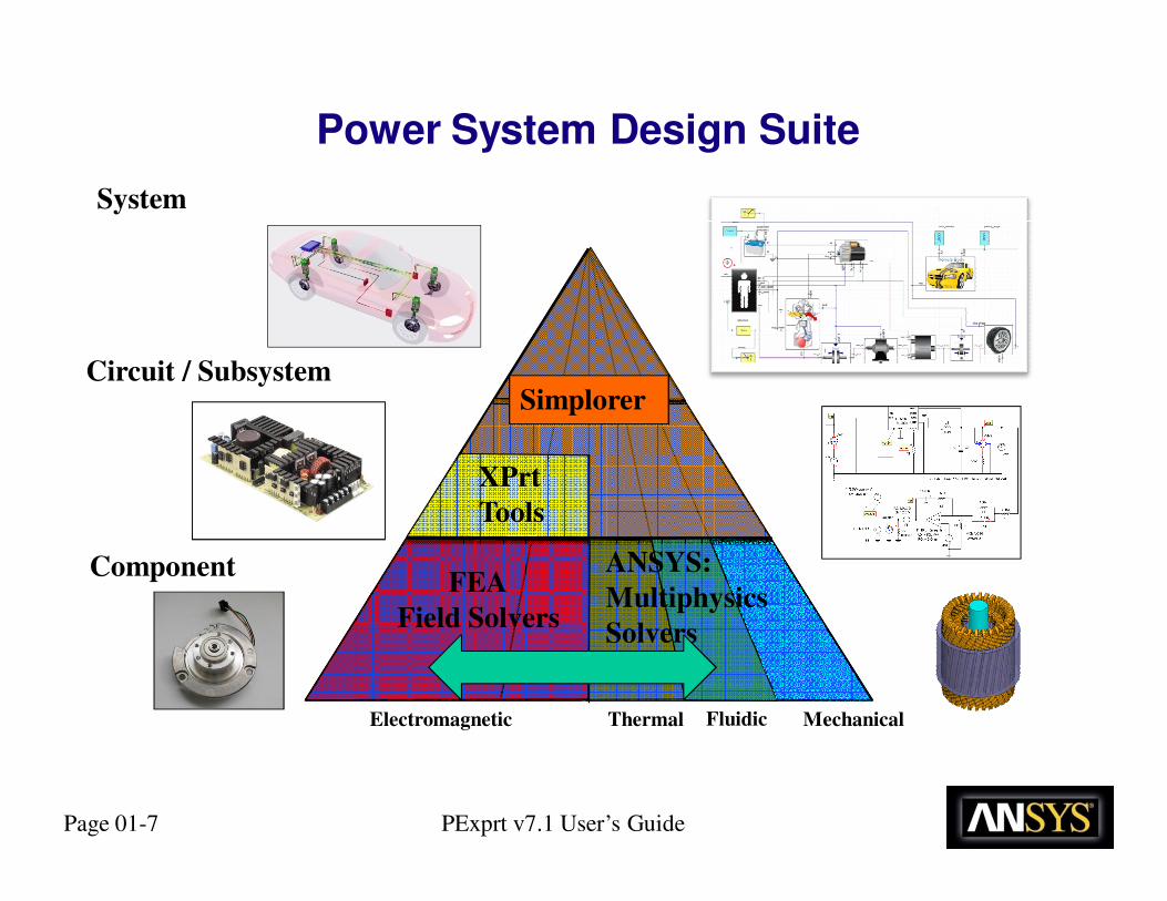
ANSYS offers the most complete solution for power systems design in the industry through its Power System Design Suite of tools
What is the Power System Design Suite of tools?
� Four combinable tools which assist engineers in designing and analyzing power systems, power supplies, and drives
� Integrates electromagnetic, circuit, and system engineering using a common desktop environment
The Power System Design Suite includes:
� PExprt – for transformer and inductor design
� Simplorer – for complete system/circuit analysis
� Maxwell 2D/3D – for finite element analysis
� Q3D Extractor – for parasitic extraction of interconnects, busbars, and cables
Power System Design Suite
Page 01-7 PExprt v7.1 User’s Guide
Power System Design Suite
ThermalElectromagnetic MechanicalFluidic
Component
Circuit / Subsystem
System
ANSYS:
Multiphysics
Solvers
XPrt
Tools
Simplorer
FEA
Field Solvers

Page 01-8 PExprt v7.1 User’s Guide
ANSYS SimplorerSystem Design
PP := 6
ICA:
A
A
A
GAIN
A
A
A
GAIN
A
JPMSYNCIA
IB
IC
Torque JPMSYNCIA
IB
IC
Torque
D2D
ANSYS Maxwell2D/3D FEA Analysis
HF/SIHFSS, Q3D, SIWave
RLCG Parasitics
ANSYS
MechanicalThermal/Stress
ANSYS CFDThermal
Model order Reduction
Co-simulation
Field Solution
FE Model Generation
OptimetricsLS-DSO
SCADE SuiteControl Systems
Embedded Design
Push Back Excitations
PExprtMagnetics
RMxprtMachine
Design

Page 01-9 PExprt v7.1 User’s Guide
Maxwell
Simplorer
ICA:
FML_INIT1
RLoad:=7.2
Engine
engine_ss
n := 3000*1.0 rpm
E1
Ra R := RLoad Ohm
Rb R := RLoad Ohm
Rc R := RLoad Ohm
V
+
V
VMphaseA
V
+
V
VMphaseB
V
+
V
VMphaseC
GeneratorMechanical Source
-180.23
179.07
-100.00
0
100.00
145.00m 150.00m146.00m 148.00m
2DGraphSel1
VMp...
VMp...
VMp...
PWR
Probe
PWR_Probe1DigViewSel1
Name Value
PWR_Probe1.VE [V] 114.18
Total_Power 5.43k
66.5
R1
2.0
EQUFML1
Total_Power := PWR_Probe1.S[0] *3
F1
F2
RMX
A
B
C
N
ROT1
ROT2
RMxprtLink11
0
4.10
2.00
0 250.00m100.00m
2DGraphSel2
E1.I [A]
▲Machines
▲RMxprt - Broad library of machine
topologies (Generators, Motors)
▲ Fully Parameterizable
▲Evaluate Machine Performance
▲Export to Maxwell 3D
▲ Export Circuit Model
▲ Simplorer
RMxprt
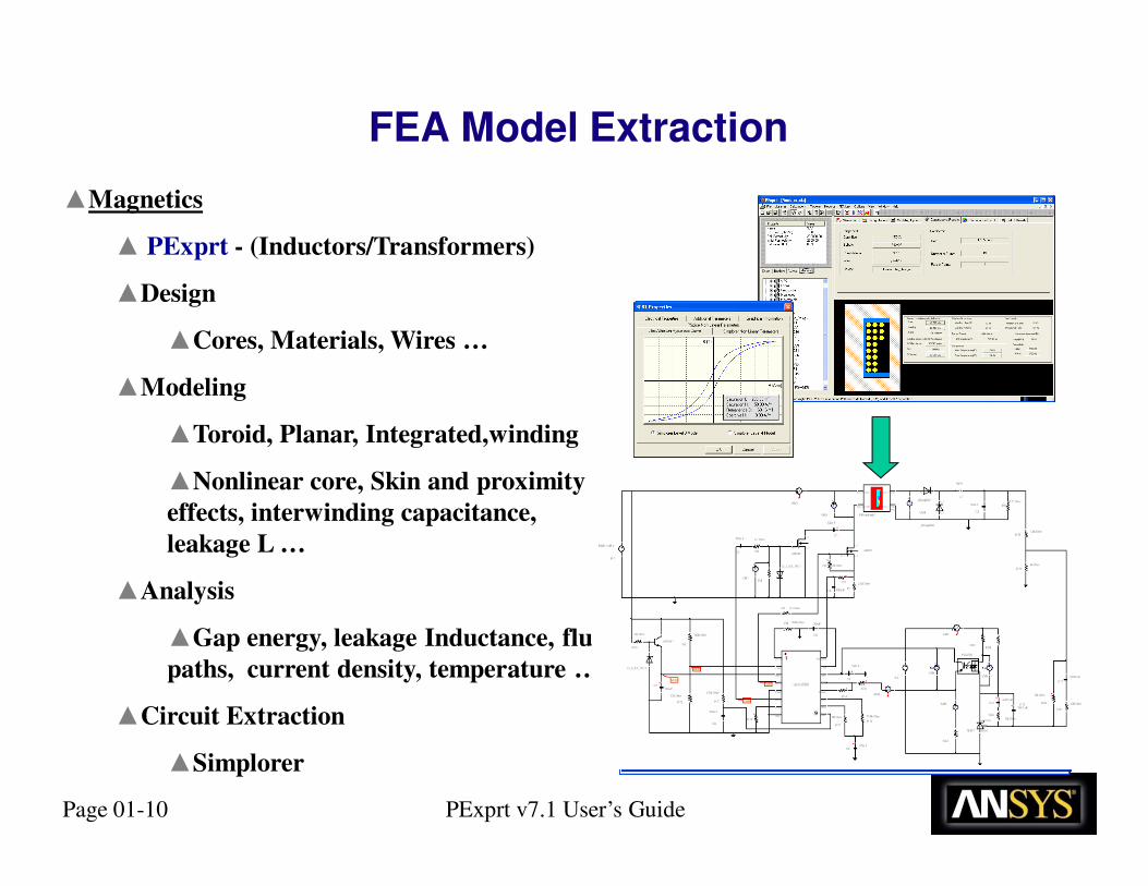
FEA Model Extraction
Page 01-10 PExprt v7.1 User’s Guide
▲Magnetics
▲ PExprt - (Inductors/Transformers)
▲Design
▲Cores, Materials, Wires …
▲Modeling
▲Toroid, Planar, Integrated,winding
▲Nonlinear core, Skin and proximity
effects, interwinding capacitance,
leakage L …
▲Analysis
▲Gap energy, leakage Inductance, flux
paths, current density, temperature …
▲Circuit Extraction
▲Simplorer
FEA Model Extraction

Page 01-11 PExprt v7.1 User’s Guide
▲Parasitics
▲ Q3D - 2D / 3D Geometry
▲ Circuit Boards, Busbar,
▲ Cables, connectors
▲ Package Parasitics
▲ Creates Z matrix with coupling
▲Circuit Extraction
▲ Simplorer
▲EMI/EMC analysis
▲CM, DM noise
FEA Model Extraction

Page 01-12 PExprt v7.1 User’s Guide
� 2D and 3D Finite Element Analysis of
� Electrical Machines
� Sensors
� Actuators
� Transformers
� RFID Systems
� Wireless Power Transfer� … and other electromagnetic and electromechanical
components
Modeling with Maxwell 2D, 3D

Page 01-13 PExprt v7.1 User’s Guide
▲Electo-Mechanical
▲Motors, Generators
▲Actuators …
▲Power Magnetics
▲Inductors, Transformers
▲Electrical Parasitics
▲PCB, Cables, bus bars
▲Thermal
▲IGBT package, CFD
▲Mechanical
▲Example Motor shafts
FEA Model Extraction Into Simplorer

Page 01-14 PExprt v7.1 User’s Guide
SimplorerSimplorer ®®
ANSYSANSYS ®® IcepakIcepak ®®
Model Model
ANSYSANSYS ®® MechanicalMechanical
ModelModel
SimplorerSimplorer®®
Temperature profile
Current profile
MaxwellMaxwell ® ® /RMxprt/RMxprt ®®
Model Model
Battery3
Battery4
Battery5
Battery0
Battery1
Battery2
Fluid Flow
Region
SimplorerSimplorer ®®
MaxwellMaxwell ®® coupled with ANSYScoupled with ANSYS ®® Mechanical Mechanical
Mapping Electromagnetic ForceMapping Power Loss
Thermal-Structural
ANSYSANSYS ®® Thermal Thermal
Model Model -- CFDCFD
High Power Inverter System

Page 01-15 PExprt v7.1 User’s Guide
0.00 2.50 5.00 7.50 10.00 12.50 15.00 17.50 20.00Time [ms]
-125.00
-100.00
-75.00
-50.00
-25.00
0.00
25.00
50.00
75.00
100.00
Y1 [V
]
Ansoft Corporation Basic_Inverter1BackEMFCurve Info
FEA1.EIT1TR
FEA1.EIT2TR
FEA1.EIT3TR
0.00 2.50 5.00 7.50 10.00 12.50 15.00 17.50 20.00Time [ms]
-200.00
-100.00
0.00
100.00
200.00
300.00
400.00
500.00
FE
A1
.TO
RQ
UE
Ansoft Corporation Basic_Inverter1TorqueCurve Info
FEA1.TORQUETR
Co-Simulation Maxwell

Page 01-16 PExprt v7.1 User’s Guide
Co-Simulation (3rd parties)
Mathcad
ModelSim® and QuestaSim® - This also allows Simplorer and its VHDL-AMS
capability to now include Verilog digital modeling.
0
22.60
10.00
20.00
0 100.00m50.00m
Motor Current
AM.I ...
Matlab/Simulink

Page 01-17 PExprt v7.1 User’s Guide
EQU
G(s)
Yt
x:= -4.7306
rating:= 10
a:= (t^(1.0/x)*rating)/(726.3^(1.0/x))
GS1
RTH1
DATAPAIRS1
CTH1
Θ
T1
RTH2therm
rload21
(S1.AC_Sim)? 1k: (S1.DC_Sim)? 1k: rload2_ctrl
TR
Probe
TR_Probe1
R2
EQU
XY
NL
XY1
NL1
I_main
sp
vset
vbus
vbus := VM1.V
D1
CONST
CONST GAIN
I LIMIT
VBUS
VSET
ERR
GAIN1
INTG1 SUM1 LIMIT1
+
V
VM1
I1
GAIN
GAIN2
engine2generator
INREG
OUTREG
GAIN
GAIN3
GAIN
GAIN4
VBUS<VSET
VBUS>=VSET
Circuit, Block, State
C code
VHDL-
AMS
FEA
Spice Import
EQUBLEquation Modeling Block
1k 10*node.V*t*f*L.I
# # i=f(v)pin
Co-Sim
(ie Simulink)
Magnetics
Simplorer’s Integrated Environment

Page 01-18 PExprt v7.1 User’s Guide
• Standard Format Allows Model Portability (IEEE standard)
– Different engineering groups within same company
– With Sub-Contractors
– Between different simulators
• Multi-level Modeling
– Different levels of abstraction of model behavior
• Multi-domain Modeling
– Electrical, Thermal, Magnetic, Mechanical, etc
• Mixed-signal Modeling
– Supports analog and digital modeling
Power of VHDL-AMS (Compatibility, Capability)

Page 01-19 PExprt v7.1 User’s Guide
heatout thermalin
rot1
c
b
a
Motor
rot1
c
b
a
m
p
Conv.c
b
aA
A
A
+
V
w
v
u
n
p
PWM Inv.
+
V
Θ
vf_full
ICA:
PWM signal
dead time
u_phase.i
w_phase.i
DC_link.v
fan
u_phase
w_phase
ctrl_5
ctrl_3
ctrl_6
ctrl_2
ctrl_1
ctrl_4
DC_link
c_freq:=650
c_rpm:=60*c_freq
mw
mu
mvst3
st6
st2
st5
st1
st4
EQU
Vmn
Vwu_mn := PI/(2.0*sqrt(2.0))*1.0/20.0m*INTEG(ABS(Vwu.V))
Vuv_mn := PI/(2.0*sqrt(2.0))*1.0/20.0m*INTEG(ABS(Vuv.V))
Vmn := (Vuv_mn + Vvw_mn + Vwu_mn)/3.0
Vvw_mn := PI/(2.0*sqrt(2.0))*1.0/20.0m*INTEG(ABS(Vvw.V))
DSP Program Model FPGA Program Model
PWM inverter Model PM Motor Model
TMS320C6701
Simplorer
RMxprt/Maxwell
VHDL-AMS
C code
Q
3
D
Motor Drive Example

Page 01-20 PExprt v7.1 User’s Guide
F1
F2
RMX
A
B
C
N
ROT 1
ROT 2
RMxprtLink1
Engine
engine_ss
n := 3000*1.0 rpm
E1
A
B
C
A
B
C
C
B
ATFR3P11
TFR3P22
+
V
VMphaseA
+
V
VMphaseB
+
V
VMphaseC
+
V
+
V
D1 D2 D3
D6D5D4
D7 D8 D9
D12D11D10
VM1
VM2Cout
3000u F
Lina 50u H Rina10m Ohm
Linb 50u H Rinb10m Ohm
Linc 50u H Rinc10m Ohm
M1
K := 0
+
VR_Load
1.4*100m
VMout
Louttop
5m H
Loutbot5m H
Generator
DC/DC Converter
Mechanical Actuator
AC/DC Conversion
+ V
TR
Probe
Am
plif
ier
Inp
ut,
Ou
tpu
t
VM
4.V
[V
]
4.00
6.00
5.00
195.00m 200.00m198.00m
Timet
Amplif ier Input, Output vs. Time
VM4....
Am
plif
ier
Inp
ut
Vo
ltag
e
E3
.V [
V]
-50.00m
50.00m
-25.00m
0
25.00m
195.00m 200.00m
Timet
Amplif ier Input Voltage vs. Time
E3.V [V]
RC
R := 1k Ohm
RE
R := 375 Ohm
Vcc
EMF := 12 V
R5
R := 365 Ohm
R2R := 140 Ohm
C2
C := 500u F
E3
AMPL := 10m V
FREQ := 1k Hz
TPERIO := Tend+1 s
C3
C := 1u F
C1C := 10n F
R3
R := 4k Ohm
R4
R := 13.7E+006 Ohm
VM4
TR_Probe1
BJT1
Electrical Loads
PW R
Probe
PWR_Probe1
0
5.50k
2.00k
4.00k
0 200.00m100.00m
2DGraphSel4
PWR_...
TFR3P21
0
28.00
10.00
20.00
0 200.00m100.00m
2DGraphSel6
VMou...
-200.00
200.00
0
158.41m 163.83m160.00m 162.00m
2DGraphSel7
VMph...
VMph... VMph...
A A
Winding current Amature force
Gap vs. time
D2D
ECE
N_1
N_2
N_3
N_4
icoil1 R6
R := 1500/1.8 Ohmforce1
igrav1
IS := 0.00545*9.807 A
D2D2LIMIT_TRB2MASS_TRB2
E4
S2
CTRL := t>=0.15
ECELink2
-5.00u
1.00m
500.00u
142.23m 196.50m
Probe4
N034...
0
16.00m
10.00m
0 200.00m100.00m
Probe5
icoil1...
-14.00
0
-5.00
0 200.00m100.00m
Probe6
force...
12v Bus
28v Bus
W
+ +
V
+
V
+
-
buck_vhdlams_dxn_ng
v gp
v gm
d1p d1m v mode
eoutm
eoutp
v loadm
v loadp
WM2
R1 VM3
rload
7.5
r487k
r1
166k
vref
4
r2
50k
c2
1479p
r3
7.45k
E5
AC_MAG 0
EMF 2.0 V
C42.5u
vopamp
E2
AC_MAG 0.0
(1/2.5)*vopamp.V
OPV54
AD := 50k V/V
F_TR := 5meg Hz
VOMIN -10
VOMAX 10
RO := 0 OhmE6
AC_MAG 1 0c1
440p
fs 200k
dutymax 1.0
l 0.53m
dutymin 0.01
R7
100meg
0
28.00
10.00
20.00
0 200.00m
Probe1
N025...
-68.00u
13.00
5.00
10.00
0 200.00m
Probe2
vout.V
PE
X
PExprtLink1
SSPC
PExprt
Simplorer
Simplorer
RMxprt
Maxwell
VHDL-AMS
Maxwell
VHDL-AMS
Power
of
ANSYS
Q3D

Page 01-21 PExprt v7.1 User’s Guide
Flyback Example
Q3DPExprt
Simplorer
Simplorer
Simplorer

Page 01-22 PExprt v7.1 User’s Guide
� PExprt® is an interactive, performance based design tool that produces
initial designs of magnetic components, such as transformers and
inductors.
� Designs can then be Modeled and Analyzed with the highest level of fidelity using FEA tools.
� Design Models can then be evaluated in the circuit using Simplorer
� Standard libraries of magnetic cores, bobbins, insulators, and conductors
allow you to define the model to your exact specifications.
� Using PExprt, you can design: inductors, multi-winding transformers, coupled inductors, and flyback components.
� Optimize constructive parameters, such as core size, core material, number of turns, air gap length, wire gauge, and winding stratagy.
PExprt - Introduction

Page 01-23 PExprt v7.1 User’s Guide
� Calculate performance parameters, such as
winding losses, core losses, flux density, DC and
AC resistance, Irms currents, magnetizing
inductance, leakage inductance, and temperature
rise.
� Consider complex effects, such as skin and
proximity effects, fringing flux near the air-gap for
energy calculations
� Calculate winding losses based on FEA field
solution and core losses.
� PExprt also includes the PEmag modeling module,
a powerful magnetic analysis module based on
finite element analysis. This module conducts a
detailed analysis of geometry, frequency, and
material
� Generate model netlists for SIMPLORER®,
electrical simulator to perform a complete system simulation of the entire device.
PExprt - Introduction

Page 01-24 PExprt v7.1 User’s Guide
▲Solves 2D and 3D electromagnetic
field problems using FEA
▲Five Solution Types: Electrostatic,
Magnetostatic, Eddy Current,
Transient Electric, Transient Magnetic
▲Determines R,L,C, forces, torques,
losses, saturation, time-induced
effects
▲Parameter extraction for:
▲Power Magnetics: Inductors,
Transformers
▲Machines: Motors, Generators,
Actuators
▲Electrical Parasitic: Cables,
vias, bus bars
Maxwell - Introduction

Page 01-25 PExprt v7.1 User’s Guide
▲Electrical Parasitic Extraction
▲ 2D / 3D Geometry
▲ Circuit Boards, Busbars
▲ Cables, Connectors
▲Interfaces with popular layout tools
▲Cadence
▲Mentor
▲Circuit Extraction
▲ Numerical Analysis (MoM)
Q3D Extractor - Introduction

Page 01-26 PExprt v7.1 User’s Guide
▲ Multi-domain, system simulator for designing
high performance systems
▲Three Basic Simulation Engines: Circuits,
Block Diagrams, State Machines
▲Mixed Signal – Mixed Mode Modeling
▲Digital / Analog
▲Magnetic, Mechanical, Thermal …
▲Integrated analysis with electromagnetic
simulation tools (Maxwell, PExprt, RMxprt, Q3D)
▲Analysis Types: AC, DC, Transient
▲Co-simulation with Maxwell and Simulink
▲Statistical Analysis and Optimization
▲VHDL-AMS Capability
SUM2_6
CONST
id_ref
G(s)
GS2
I
I_PART_id
GAIN
idLIMIT
yd
UL := 9
LL := -9
GAIN
P_PART_id
KP := 0.76
12
R1 R2 R3 R450
1k 1k50
C1 C2
3.3u
3.3u
V0 := 5 V0 := 0
N0005
N0003N0004
N0002
IMP = 0
IMP = 1IMP = 0
IMP = 1
IMP = 0 and RLine.I <= ILOW
IMP = 1 and RLine.I >= IUP
IMP = 0 and RLine.I >= IUP
IMP = 1 and RLine.I <= ILOW
SET: CS1:=-1SET: CS2:=-1SET: CS3:=-1SET: CS4:=-1
SET: CS1:=-1SET: CS2:=1SET: CS3:=-1SET: CS4:=-1
SET: CS1:=1SET: CS2:=-1SET: CS3:=-1SET: CS4:=-1
SET: CS1:=-1SET: CS2:=-1SET: CS3:=-1SET: CS4:=-1
Circuits
Block Diagrams
State Machines
Simplorer - Introduction