pg105 convection enhanced pirani gauge - stanford research
TRANSCRIPT
www.thinkSRS.com 1
(408)744-9040 Stanford Research Systems www.thinkSRS.com
PG105 Convection Enhanced Pirani Gauge
The SRS PG105 is a convection-enhanced Pirani gauge (CEPG) manufactured by Stanford Research Systems. When used with an IGC100 controller the PG105 provides a convenient, reliable and low-cost measurement of vacuum over a wide pressure range extending from atmosphere to 10-4 Torr.
This appendix provides a detailed description of the principle of operation, construction, gas dependence, calibration and fundamental strengths and weaknesses of the PG105 gauge head. Application examples and a few practical tips are provided along the way. Basic maintenance and troubleshooting information are also included.
Since it is not possible to cover this complex gauge in such a short note, a comprehensive list of references is provided at the end.
In This Application Note Principle of Operation 3 Construction 6 Calibration 8 Accuracy and Stability 9 Operation Below 10-3 Torr 10 Mounting Orientation 10 Mounting Recommendations 11
Handling 11 Location 11 Temperature 12 Vibration 12 Grounding 12 Compression fittings 12 1/8 NPT Fittings 12 Other Fittings 12
Contamination 13 Cleaning 14
Materials 14 Cleaning Procedure 14
Bakeout 15
Application Examples and Tips 15 Safety Considerations 17
Explosive Gases 17 Compression Mounts 17 Overpressure Risks 18 Grounding 18
Electrical Connection 19 PG105 Gauge Test Procedure 20 References 21
PG105 Convection Enhanced Pirani Gauge
Stanford Research Systems (408)744-9040 www.thinkSRS.com
2
PG105 Convection Enhanced Pirani Gauge
(408)744-9040 Stanford Research Systems www.thinkSRS.com
3
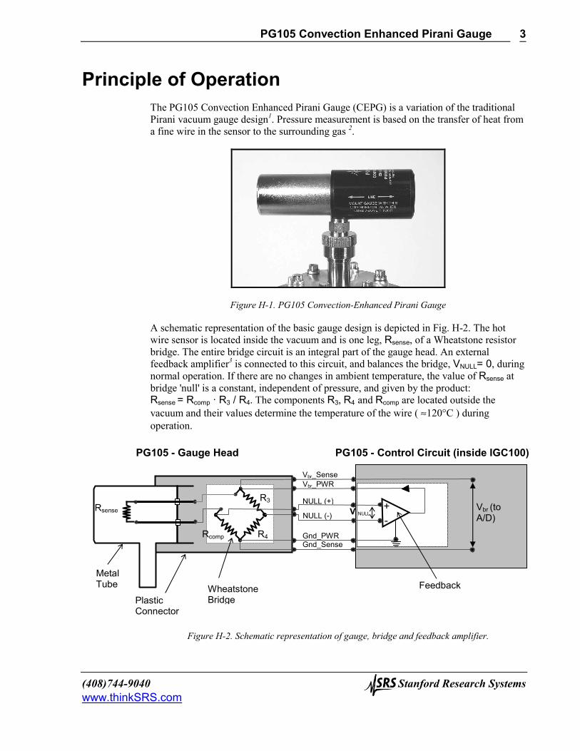
Principle of Operation The PG105 Convection Enhanced Pirani Gauge (CEPG) is a variation of the traditional Pirani vacuum gauge design1. Pressure measurement is based on the transfer of heat from a fine wire in the sensor to the surrounding gas 2.
Figure H-1. PG105 Convection-Enhanced Pirani Gauge
A schematic representation of the basic gauge design is depicted in Fig. H-2. The hot wire sensor is located inside the vacuum and is one leg, Rsense, of a Wheatstone resistor bridge. The entire bridge circuit is an integral part of the gauge head. An external feedback amplifier3 is connected to this circuit, and balances the bridge, VNULL= 0, during normal operation. If there are no changes in ambient temperature, the value of Rsense at bridge 'null' is a constant, independent of pressure, and given by the product: Rsense = Rcomp · R3 / R4. The components R3, R4 and Rcomp are located outside the vacuum and their values determine the temperature of the wire ( ≈120°C ) during operation.
Figure H-2. Schematic representation of gauge, bridge and feedback amplifier.
R3
R4
Rsense
Rcomp -+
Vbr_Sense Vbr_PWR
NULL (+)
NULL (-)
Gnd_PWR Gnd_Sense
V NULLVbr (to A/D)
Metal Tube
Plastic Connector
Wheatstone Bridge
Feedback
PG105 - Gauge Head PG105 - Control Circuit (inside IGC100)
PG105 Convection Enhanced Pirani Gauge
Stanford Research Systems (408)744-9040 www.thinkSRS.com
4
In a gaseous environment the hot wire loses heat in four ways4: (1) radiation, (2) conduction along the wire to the end supports (3) heat conduction by the gas molecules and (4) gas convection. The energy transfer by the gas is pressure-dependent and driven by the temperature difference between the wire and the outer walls. As the vacuum system pressure is decreased, there are fewer molecules in the system to conduct heat away from the wire causing the temperature and Rsense to increase. The increased resistance of Rsense unbalances the bridge causing a voltage differential between the NULL terminals, VNULL≠ 0. The bridge control circuit senses the NULL voltage change and decreases the voltage across the bridge, Vbr, until VNULL is again zero. Once the bridge voltage is decreased, the power dissipated by the sensor wire is decreased bringing the resistance of Rsense back to its original value. Obviously, the opposite set of events occurs when the pressure is increased. The bridge voltage, Vbr, is read by the controller and used as a non-linear measure of pressure. As with all Pirani gauges, the voltage output depends on pressure as well as the thermal conductivity of the surrounding gases (i.e. indirect pressure measurement) - the gas composition must be known in order to indicate pressures correctly.
IMPORTANT With a Pirani gauge, you need to know the gases you are pumping and calibrate the gauge for those gases before you can measure true vacuum levels.
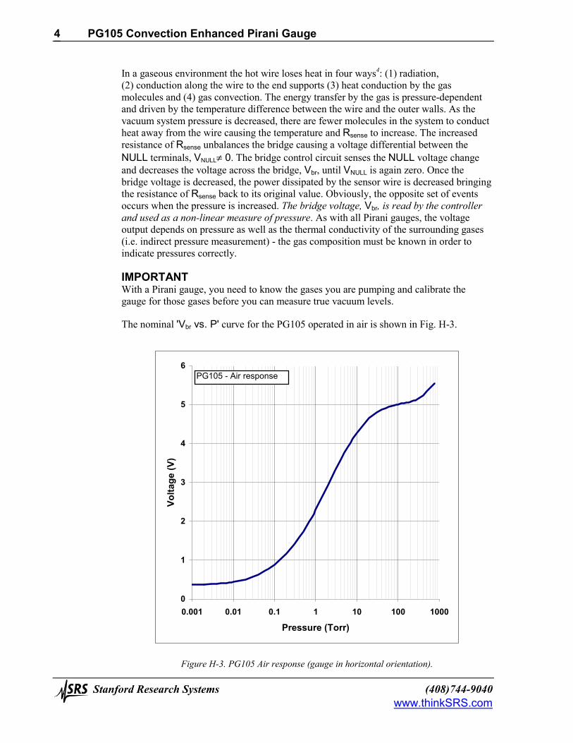
The nominal 'Vbr vs. P' curve for the PG105 operated in air is shown in Fig. H-3.
0
1
2
3
4
5
6
0.001 0.01 0.1 1 10 100 1000
Pressure (Torr)
Volta
ge (V
)
PG105 - Air response
Figure H-3. PG105 Air response (gauge in horizontal orientation).
PG105 Convection Enhanced Pirani Gauge
(408)744-9040 Stanford Research Systems www.thinkSRS.com
5
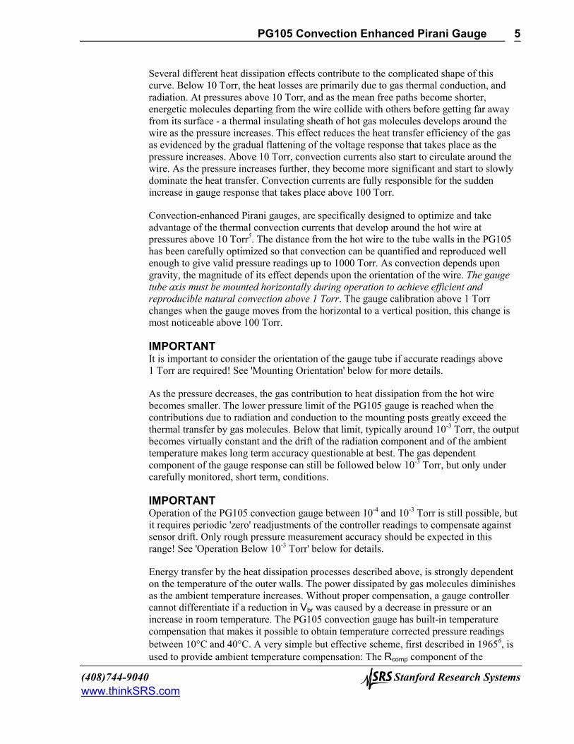
Several different heat dissipation effects contribute to the complicated shape of this curve. Below 10 Torr, the heat losses are primarily due to gas thermal conduction, and radiation. At pressures above 10 Torr, and as the mean free paths become shorter, energetic molecules departing from the wire collide with others before getting far away from its surface - a thermal insulating sheath of hot gas molecules develops around the wire as the pressure increases. This effect reduces the heat transfer efficiency of the gas as evidenced by the gradual flattening of the voltage response that takes place as the pressure increases. Above 10 Torr, convection currents also start to circulate around the wire. As the pressure increases further, they become more significant and start to slowly dominate the heat transfer. Convection currents are fully responsible for the sudden increase in gauge response that takes place above 100 Torr.
Convection-enhanced Pirani gauges, are specifically designed to optimize and take advantage of the thermal convection currents that develop around the hot wire at pressures above 10 Torr5. The distance from the hot wire to the tube walls in the PG105 has been carefully optimized so that convection can be quantified and reproduced well enough to give valid pressure readings up to 1000 Torr. As convection depends upon gravity, the magnitude of its effect depends upon the orientation of the wire. The gauge tube axis must be mounted horizontally during operation to achieve efficient and reproducible natural convection above 1 Torr. The gauge calibration above 1 Torr changes when the gauge moves from the horizontal to a vertical position, this change is most noticeable above 100 Torr.
IMPORTANT It is important to consider the orientation of the gauge tube if accurate readings above 1 Torr are required! See 'Mounting Orientation' below for more details.
As the pressure decreases, the gas contribution to heat dissipation from the hot wire becomes smaller. The lower pressure limit of the PG105 gauge is reached when the contributions due to radiation and conduction to the mounting posts greatly exceed the thermal transfer by gas molecules. Below that limit, typically around 10-3 Torr, the output becomes virtually constant and the drift of the radiation component and of the ambient temperature makes long term accuracy questionable at best. The gas dependent component of the gauge response can still be followed below 10-3 Torr, but only under carefully monitored, short term, conditions.
IMPORTANT Operation of the PG105 convection gauge between 10-4 and 10-3 Torr is still possible, but it requires periodic 'zero' readjustments of the controller readings to compensate against sensor drift. Only rough pressure measurement accuracy should be expected in this range! See 'Operation Below 10-3 Torr' below for details.
Energy transfer by the heat dissipation processes described above, is strongly dependent on the temperature of the outer walls. The power dissipated by gas molecules diminishes as the ambient temperature increases. Without proper compensation, a gauge controller cannot differentiate if a reduction in Vbr was caused by a decrease in pressure or an increase in room temperature. The PG105 convection gauge has built-in temperature compensation that makes it possible to obtain temperature corrected pressure readings between 10°C and 40°C. A very simple but effective scheme, first described in 19656, is used to provide ambient temperature compensation: The Rcomp component of the
PG105 Convection Enhanced Pirani Gauge
Stanford Research Systems (408)744-9040 www.thinkSRS.com
6
Wheatstone bridge is not a simple resistor as sketched in Fig. H-2, but rather a composite, temperature-sensitive, resistor network made up to have a temperature coefficient (R4/R3) times that of Rsense. A thin metal wire, with a high temperature coefficient of resistance, tightly wound around the outer diameter of the gauge tube, provides the temperature sensitive component of the network. The other components of the resistor network have relatively insignificant temperature coefficients and are carefully selected at the factory to trim the effective temperature coefficient of Rcomp to the required value. Under this simple bridge configuration, a constant temperature difference is maintained between the wire and the walls at all times, and bridge voltages are relatively unaffected by ambient temperature changes. In addition to compensating for ambient temperature variations, this compensation scheme also corrects for heating of the gauge envelope due to filament dissipation at high pressures. At atmospheric pressure, the dissipation of ≈1/8 Watt from the hot filament can cause a slow temperature rise of a few degrees Celsius at the tube’s outer wall. Temperature compensation is vital if the gauge output is to have any real meaning above 100 Torr. It also effectively reduces the time required to obtain accurate and stable pressure readings after a rapid pressure change.
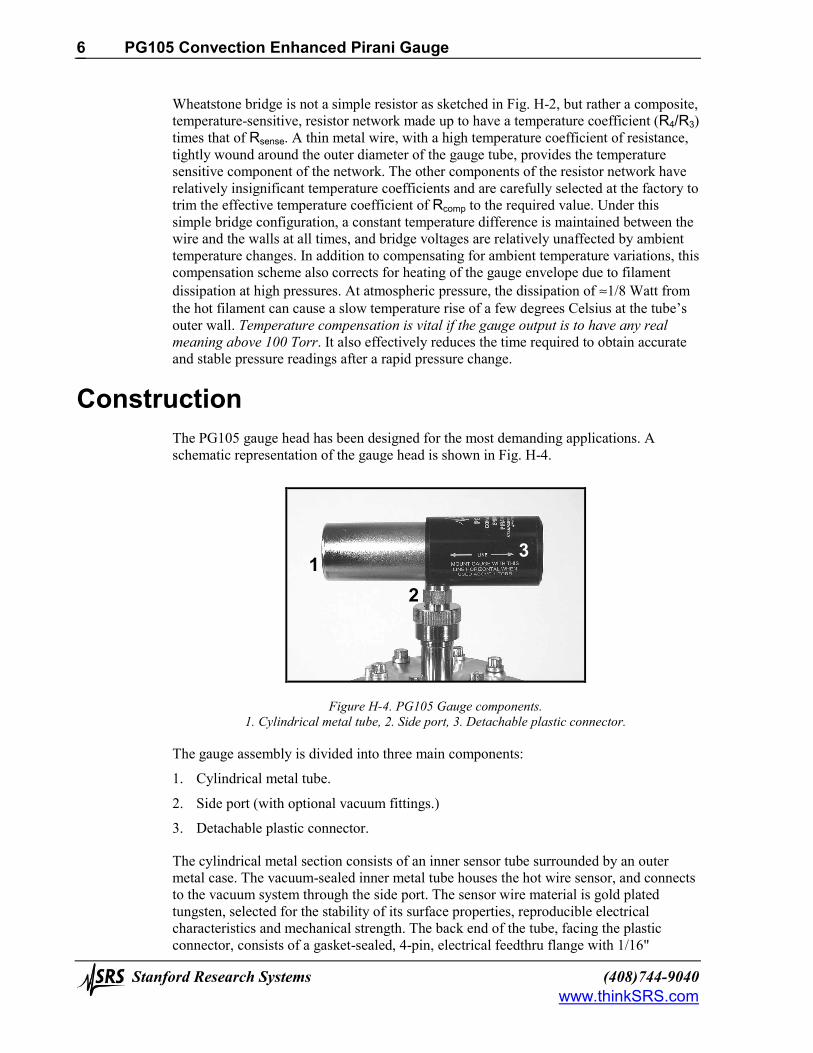
Construction The PG105 gauge head has been designed for the most demanding applications. A schematic representation of the gauge head is shown in Fig. H-4.
Figure H-4. PG105 Gauge components. 1. Cylindrical metal tube, 2. Side port, 3. Detachable plastic connector.
The gauge assembly is divided into three main components:
1. Cylindrical metal tube.
2. Side port (with optional vacuum fittings.)
3. Detachable plastic connector.
The cylindrical metal section consists of an inner sensor tube surrounded by an outer metal case. The vacuum-sealed inner metal tube houses the hot wire sensor, and connects to the vacuum system through the side port. The sensor wire material is gold plated tungsten, selected for the stability of its surface properties, reproducible electrical characteristics and mechanical strength. The back end of the tube, facing the plastic connector, consists of a gasket-sealed, 4-pin, electrical feedthru flange with 1/16"
1 3
2
PG105 Convection Enhanced Pirani Gauge
(408)744-9040 Stanford Research Systems www.thinkSRS.com
7
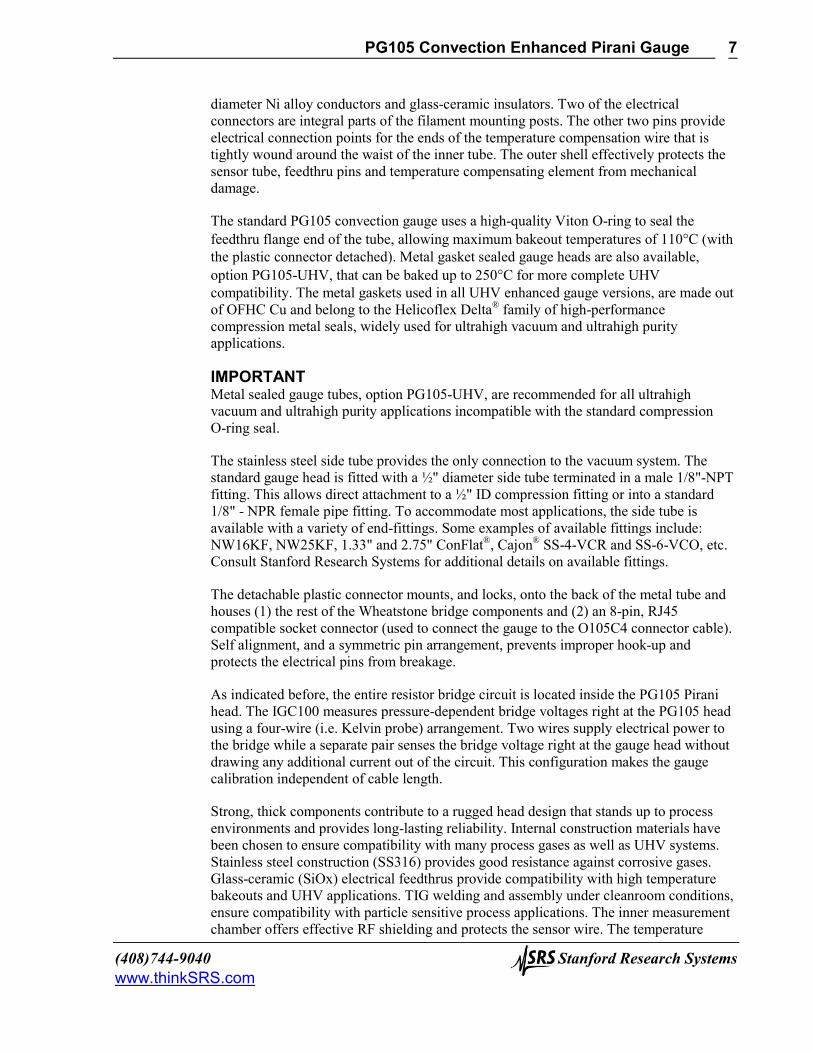
diameter Ni alloy conductors and glass-ceramic insulators. Two of the electrical connectors are integral parts of the filament mounting posts. The other two pins provide electrical connection points for the ends of the temperature compensation wire that is tightly wound around the waist of the inner tube. The outer shell effectively protects the sensor tube, feedthru pins and temperature compensating element from mechanical damage.
The standard PG105 convection gauge uses a high-quality Viton O-ring to seal the feedthru flange end of the tube, allowing maximum bakeout temperatures of 110°C (with the plastic connector detached). Metal gasket sealed gauge heads are also available, option PG105-UHV, that can be baked up to 250°C for more complete UHV compatibility. The metal gaskets used in all UHV enhanced gauge versions, are made out of OFHC Cu and belong to the Helicoflex Delta® family of high-performance compression metal seals, widely used for ultrahigh vacuum and ultrahigh purity applications.
IMPORTANT Metal sealed gauge tubes, option PG105-UHV, are recommended for all ultrahigh vacuum and ultrahigh purity applications incompatible with the standard compression O-ring seal.
The stainless steel side tube provides the only connection to the vacuum system. The standard gauge head is fitted with a ½" diameter side tube terminated in a male 1/8"-NPT fitting. This allows direct attachment to a ½" ID compression fitting or into a standard 1/8" - NPR female pipe fitting. To accommodate most applications, the side tube is available with a variety of end-fittings. Some examples of available fittings include: NW16KF, NW25KF, 1.33" and 2.75" ConFlat®, Cajon® SS-4-VCR and SS-6-VCO, etc. Consult Stanford Research Systems for additional details on available fittings.
The detachable plastic connector mounts, and locks, onto the back of the metal tube and houses (1) the rest of the Wheatstone bridge components and (2) an 8-pin, RJ45 compatible socket connector (used to connect the gauge to the O105C4 connector cable). Self alignment, and a symmetric pin arrangement, prevents improper hook-up and protects the electrical pins from breakage.
As indicated before, the entire resistor bridge circuit is located inside the PG105 Pirani head. The IGC100 measures pressure-dependent bridge voltages right at the PG105 head using a four-wire (i.e. Kelvin probe) arrangement. Two wires supply electrical power to the bridge while a separate pair senses the bridge voltage right at the gauge head without drawing any additional current out of the circuit. This configuration makes the gauge calibration independent of cable length.
Strong, thick components contribute to a rugged head design that stands up to process environments and provides long-lasting reliability. Internal construction materials have been chosen to ensure compatibility with many process gases as well as UHV systems. Stainless steel construction (SS316) provides good resistance against corrosive gases. Glass-ceramic (SiOx) electrical feedthrus provide compatibility with high temperature bakeouts and UHV applications. TIG welding and assembly under cleanroom conditions, ensure compatibility with particle sensitive process applications. The inner measurement chamber offers effective RF shielding and protects the sensor wire. The temperature
PG105 Convection Enhanced Pirani Gauge
Stanford Research Systems (408)744-9040 www.thinkSRS.com
8
compensation element is located outside the vacuum to reduce outgassing and preserve UHV compatibility. Gold plated tungsten sensor construction helps minimize calibration drift (see 'Contamination' section below). A very thin and long sensor wire is used to minimize heat loss to the end supports and minimize temperature gradients along its length. This is very important for operating below 10-3 Torr.
The following materials are exposed to the vacuum:
1. Type 316 stainless steel
2. Carpenter glass sealing "52" alloy™ (50.5% Ni/Fe alloy)
3. Gold plated tungsten
4. Glass ceramic (SiOx ceramic)
5. Viton (standard, O-ring sealed, heads only)
6. OFHC Copper (PG105-UHV heads only)
Note There is no brazing material in the ceramic feedthrus- the glass ceramic wets right on to the stainless steel. No solder or solder flux material is used inside the gauge tube.
Calibration Following factory assembly, each PG105 gauge tube is individually calibrated for nitrogen, and temperature compensated between 10° and 40°C. After calibration, each gauge tube is then individually tested to determine if selected pressure readouts fall within narrow limits before the unit is ready for shipment. Individual factory calibration of the gauge response provides true 'plug-and-play' convenience and eliminates the need to rezero the controller each time a new gauge tube is connected7. PG105 gauges and IGC100 controllers are completely interchangeable without any need for instrument adjustments! In order to assure that calibration does not change with use, all gauge tubes are baked at high temperature for an extended period of time before final calibration takes place.
It is important to understand that the pressure indicated by a PG105 convection gauge depends on (1) the type of gas, (2) the orientation of the gauge axis and (3) the gas density inside the gauge tube. As mentioned before, the PG105 gauge is factory calibrated and temperature compensated for nitrogen gas. However the response of the gauge for gases other than nitrogen is very well characterized and, with the proper calibration data (i.e. Vbr vs. P curve for the specific gas type), it is possible to obtain accurate pressure measurements for other gases.
IGC100 controllers are factory loaded with nitrogen and argon specific calibration curves compatible with all PG105 convection gauges8. The non-linear dependence of the bridge voltage on pressure is evident from Fig. H-3, and shows the need for detailed lookup tables to obtain accurate readings over the entire pressure range.
Note Gas correction curves and correction factors, used to convert 'nitrogen equivalent pressure' readings into true pressure readings for some common gases, can be found in

PG105 Convection Enhanced Pirani Gauge
(408)744-9040 Stanford Research Systems www.thinkSRS.com
9
the application note, 'Gas Correction Curves for PG105 Readings'. The conversion curves only apply when the pressure readings displayed by the controller are based on the nitrogen calibration curve and the gauge tube is mounted with its axis horizontal. Use the curves or correction factors (where applicable) to convert indicated (i.e. nitrogen equivalent) pressure readings into true pressures for all the gases included in the application note.
Users should generate their own conversion curves for gases, or mixtures of gases, not listed in the application note. A calibrated, gas-independent, capacitance manometer is recommended as a transfer standard.
WARNING! A serious danger of explosion can arise if the calibration data for one gas is applied without correction to measure pressures for a different gas (or gases) at or above atmospheric pressure. Please consult the 'Safety Considerations' section below for information on overpressure risks.
The calibration data loaded into all IGC100 controllers is based on the response of a new gauge free of contaminants. If a tube becomes contaminated or does not seem to read correctly, the front panel readings can often be readjusted using the ZERO and ATM adjustments in the Pirani Gauge calibration menu. Consult the IGC100 instructions for details on these two adjustment procedures.
Note The ZERO and ATM adjustments built into the IGC100 controller make it possible to accommodate considerable changes in PG105 calibration while retaining acceptable measurement accuracy.
Accuracy and Stability Very limited information exists in the vacuum literature on the accuracy, repeatability and long term stability of measurements made with thermal conductivity vacuum gauges. This is probably because most of the users that rely on these gauges for their applications do not require high accuracy pressure reports!
The measurement accuracy of all convection gauges (including the PG105) is pressure dependent and generally between 5% to 20% of the indicated pressure9. Accuracies not better than 25% should be expected from convection gauges used at atmospheric pressures10. Highest accuracies are usually observed between 1 and 10-2 Torr.
Because the pressure range where gas conduction cooling is predominant does not neatly overlap the pressure range where convection cooling occurs (see Fig. H-3), all convection enhanced Pirani gauges have limited sensitivity between 20 and 200 Torr11.
Only one relevant study on the long term performance of constant temperature Pirani gauges has appeared in the vacuum literature12. Over the six months of the study, the gauges tested showed reproducibilities within ±6% over the pressure range extending from 10-2 to 10 Torr. Similar stability should probably be expected from PG105 gauges

PG105 Convection Enhanced Pirani Gauge
Stanford Research Systems (408)744-9040 www.thinkSRS.com
10
used under controlled conditions. However, always remember that the operating environment conditions ultimately limit the long term performance of a vacuum gauge! Also remember that the ZERO and ATM adjustments built into the IGC100 controller often make it possible to accommodate slight changes in tube characteristics while still retaining acceptable reading accuracy.
Periodic comparison at several pressures against a reliable check standard is recommended to determine if gross changes in response have occurred, and to determine if readjustment, bakeout , cleaning or full replacement is necessary.
Operation Below 10-3 Torr Variations in ambient temperature and wire contamination are the two major sources of instability for readings below 10-3 Torr, where radiation and conduction to the mounting posts dominate the heat transfer process. The emissivity of a wire might vary from 0.05 for a clean wire to unity when contaminated. Power dissipation due to radiation is a function of the fourth power of the filament temperature. As a result, operation of the PG105 convection gauge below 10-3 Torr (where molecular conduction contributes as little as 1% of the total heat dissipation) is still possible, but it requires periodic ZERO readjustments of the controller readings to compensate against background drift.
Only rough pressure measurement accuracy should be expected below 10-3 Torr!
During fast pumpdown, thermal effects will prevent the PG105 gauge from providing immediate accurate pressure readings below 10-3 Torr. Readings in the 10-4 Torr range are valid only after a 15-20 minute period of thermal stabilization. ZERO adjustments of the controller readings should not be performed until full thermal stabilization has been accomplished.
IMPORTANT For accurate results in the 10-4 Torr range, ZERO readjustments of the controller readings should be performed periodically.
The peak-to-peak random noise for pressure measurements below 10-3 Torr is ±1.5x10⁻⁴ Torr (nom) for all IGC100 controllers.
Mounting Orientation Below 1 Torr The PG105 convection gauge will operate and report accurate pressures in any orientation.
Above 1 Torr The PG105 convection gauge will accurately read pressures only while mounted with its axis horizontal.
In both cases, it is recommended that the gauge be installed with the port oriented vertically downward to ensure that no system condensates or other liquids collect inside the gauge tube.
PG105 Convection Enhanced Pirani Gauge
(408)744-9040 Stanford Research Systems www.thinkSRS.com
11
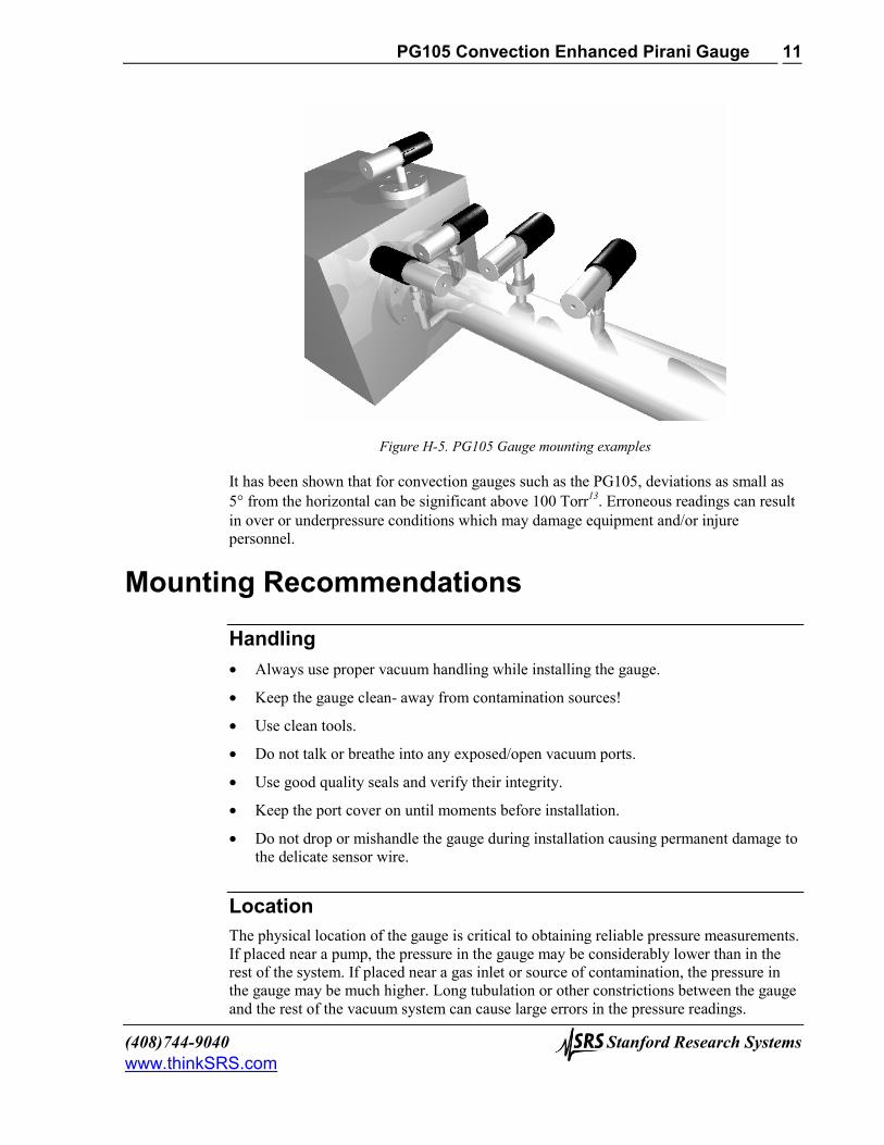
Figure H-5. PG105 Gauge mounting examples
It has been shown that for convection gauges such as the PG105, deviations as small as 5° from the horizontal can be significant above 100 Torr13. Erroneous readings can result in over or underpressure conditions which may damage equipment and/or injure personnel.
Mounting Recommendations
Handling • Always use proper vacuum handling while installing the gauge.
• Keep the gauge clean- away from contamination sources!
• Use clean tools.
• Do not talk or breathe into any exposed/open vacuum ports.
• Use good quality seals and verify their integrity.
• Keep the port cover on until moments before installation.
• Do not drop or mishandle the gauge during installation causing permanent damage to the delicate sensor wire.
Location The physical location of the gauge is critical to obtaining reliable pressure measurements. If placed near a pump, the pressure in the gauge may be considerably lower than in the rest of the system. If placed near a gas inlet or source of contamination, the pressure in the gauge may be much higher. Long tubulation or other constrictions between the gauge and the rest of the vacuum system can cause large errors in the pressure readings.
PG105 Convection Enhanced Pirani Gauge
Stanford Research Systems (408)744-9040 www.thinkSRS.com
12
Temperature Minimize temperature effects - locate the gauge away from internal and external heat sources. Whenever possible, choose an area where the ambient temperature is reasonably constant.
Vibration Mount PG105 gauges where they will not experience excessive vibrations. Vibration causes convection cooling of the sensor and results in high readings at the high pressure end. Damage to the filament is also possible.
Grounding Verify the proper electrical grounding of the vacuum port before connecting the PG105 gauge head to the vacuum system. The gauge envelope must be properly grounded during operation. If necessary, use a ground lug on a flange bolt to establish a dedicated connection to a facility ground. Alternatively, the gauge envelope may be grounded by using a metal hose clamp on the gauge connected to the system’s safety ground by a #12 AWG copper wire.
Compression fittings The standard PG105 gauge port is designed to fit any standard ½" compression fitting such as an Ultra-Torr® fitting. Do not use compression fittings for positive pressure applications!
1/8 NPT Fittings The threads on the standard PG105 side port will fit a standard 1/8" NPT female fitting. Wrap the gauge threads with Teflon tape and screw the gauge into the female fitting. Twist the gauge body by hand until the first sign of resistance is felt. Do not use the body of the gauge as its own wrench past this point. Instead, finish tightening with a ½" wrench applied to the nut built into the side tube until a proper seal is achieved. Do not overtighten as that might stress the tube port!
Other Fittings In addition to the standard tube, which provides a ½" compression port and a 1/8" NPT male thread, a variety of other mounting options are available. They include: NW16KF, NW25KF, 1.33" and 2.75" ConFlat®, Cajon® SS-4-VCR and SS-6-VCO, etc. Consult Stanford Research Systems for additional information on available fittings.
PG105 Convection Enhanced Pirani Gauge
(408)744-9040 Stanford Research Systems www.thinkSRS.com
13
Contamination Contamination of the sensor wire with pump oil or other films is the main source of calibration drifts in Pirani gauges.
Wire material and temperature14 play the most important role in the long-term performance of the PG105 convection gauge.
A gold-plated tungsten wire is used in all PG105 gauge tubes. This material was selected for the stability of its surface properties, reproducible electrical characteristics and mechanical strength. Gold plating minimizes wire contamination as caused by oxidation, corrosion and surface induced decomposition reactions. A shiny gold surface offers the low emissivity levels required to extend the low limit of the gauge into the sub-mTorr pressure range.
The temperature of the wire inside the PG105 gauge tube is approximately 120°C during operation. This temperature delivers optimal gauge response15 while, at the same time, it remains low enough to minimize contamination by surface induced decomposition of foreign materials, such as pump-oil vapors.
Care must be taken not to mount the PG105 tube in a way such that deposition of process vapor impurities may occur through direct line-of-sight access from the vacuum chamber to the interior of the gauge.
It is also recommended that the PG105 tube be installed with the side port oriented vertically downward to ensure that no system condensates or other liquids collect inside the gauge tube.
IMPORTANT PG105 gauges should not be used in the presence of fluorine or mercury vapors. Both gases can react with the gold plated sensor and change its emissivity and/or overall diameter irreversibly.
Surface contamination strongly affects both the emissivity and accommodation coefficient16 of the hot wire. Changes in emissivity affect the stability of the background, and effectively set the lower operating limit of a Pirani gauge during actual use. Periodic ZERO readjustments of the controller readings, to compensate against background drift, are required for operation in the millitorr and especially in the sub-millitorr range. Changes in surface properties result in changes in the efficiency of heat conduction by the gas molecules and cause calibration drifts. If, and when, contamination causes the PG105 calibration to change, the user can correct the pressure readings displayed by the IGC100 controller performing a quick ATM readjustment of the controller readings at atmospheric pressure.
The ZERO and ATM(mosphere) adjustments built into the IGC100 controller make it possible to accommodate considerable changes in tube characteristics while retaining acceptable measurement accuracy.

PG105 Convection Enhanced Pirani Gauge
Stanford Research Systems (408)744-9040 www.thinkSRS.com
14
Periodic gauge bakeouts provide an effective way to avoid serious contamination buildup problems. Maximum bakeout temperatures are 110°C for standard (i.e. O-ring sealed) heads, and 250°C for metal-gasket sealed tubes (option PG105-UHV). The plastic connector must be disconnected from the head during bakeouts. An overnight bakeout, at ≈200°C, is the only recommended cleaning procedure for PG105-UHV gauges in direct contact with ultra high vacuum environments.
The calibration of grossly contaminated convection gauges can sometimes be partially restored using the solvent-based cleaning procedure described in the next section. This cleaning procedure is mostly recommended for gauges heavily contaminated by hydrocarbon impurities originated from vacuum pumps.
Cleaning
WARNING! • This cleaning procedure should only be used on severely contaminated gauges, when
the ZERO and ATM controller adjustments can no longer correct for drifts in the calibration.
• Stanford Research Systems does not guarantee that this procedure will remove contamination from a PG105 convection gauge.
• Use this cleaning method as a last resort only!
WARNING! The fumes from acetone and isopropyl alcohol can be dangerous to health if inhaled and are highly flammable. Work in well ventilated areas and away from ignition sources!
Materials 1. Isopropyl alcohol or acetone, electronic grade or better.
2. Wash bottle with long thin neck.
Cleaning Procedure Disconnect the gauge from the electrical cable and from the vacuum system port. Physically disconnect the detachable plastic connector from the back of the gauge tube and store it in a safe and clean place.
Hold the metal gauge tube in a horizontal position with the side port pointing upwards at a 45° angle. Slowly fill the volume of the gauge with solvent using the wash bottle to squirt the liquid into the side tube. Let the solvent stand inside the gauge for at least 10 minutes. Do not shake the gauge, since that might cause damage to the sensor wire. To drain the gauge, position it horizontally with the side port facing downward. Slightly warming the gauge will help dry the gauge. Allow the gauge tube to dry overnight with

PG105 Convection Enhanced Pirani Gauge
(408)744-9040 Stanford Research Systems www.thinkSRS.com
15
the port facing downward. Before reinstalling the gauge in the system, be certain no solvent odor remains.
Viton O-rings soaked in organic liquids can outgas solvent molecules for extended periods of time. Solvent outgassing rates can be significantly diminished: (a) baking the gauge tube overnight in a vacuum oven between 100-110°C before gauge installation or (b) baking out the gauge while attached to the vacuum system and before reconnecting its plastic connector.
Bakeout
WARNING! The detachable plastic connector must be physically disconnected from the PG105 gauge head during bakeout.
Figure H-6. Side view of the PG105 gauge tube with the detachable plastic connector disconnected.
Periodic, overnight, gauge bakeouts provide an effective way to minimize contamination buildup problems. Maximum bakeout temperatures are 110°C for standard (i.e. Viton O-ring sealed) heads, and 250°C for metal-gasket sealed tubes (option PG105-UHV) used in UHV or low contamination applications.
An overnight bakeout, at 200-250°C, is the only recommended cleaning procedure for PG105-UHV gauges in direct contact with ultra high vacuum environments.
Application Examples and Tips Convection gauges, such as the PG105, are an accurate, fast and inexpensive means of measuring foreline and roughing line pressures, or moderate backfill pressures!
The PG105 convection enhanced Pirani gauge is the best choice for vacuum applications where conventional thermocouple and Pirani gauges are not suitable because of (1) limited range, (2) drift and (3) slow response. It is often selected as a cost effective alternative to a capacitance manometer17.

PG105 Convection Enhanced Pirani Gauge
Stanford Research Systems (408)744-9040 www.thinkSRS.com
16
The exceptionally wide measurement range of the PG105 makes it possible to continuously monitor the pumpdown of a vacuum system from atmospheric to the base pressure of most mechanical pumps without any blind spots. Convection gauges are found in virtually every modern semiconductor and thin film process system, for monitoring pumping system performance.
Convection gauges are the type of vacuum gauge most commonly encountered on loadlocks18 and are often used to tell when a chamber may be safe to open to atmosphere. Yet, a convection gauge alone may not be accurate enough to tell you when there is enough internal positive pressure to ensure a gentle flow of gas out of the chamber once you open the door. For this reason, many users combine their convection gauges with differential pressure devices called atmospheric pressure switches.
A response time of a few milliseconds makes the PG105 convection gauge ideally suited for protective functions, such as determining when BAG emission should be de-activated or turned off. They are also well suited to control valves, heaters, bakeout ovens and safety interlocks.
Gas dependence makes the PG105 useful as an inexpensive leak detector. By using a tracer gas whose thermal conductivity is very different from the gases in the vacuum system, leaks as small as 10-4 atm cc/sec can be sensed and located. Typical gases used for leak testing include hydrogen, helium, argon and freon. This can eliminate the need for a very expensive leak detector. Several applications of Pirani gauges to leak detection have been reported in the vacuum literature19.
The PG105 convection gauge is ideal for applications that operate between atmosphere and a few microns, and where gas composition is well known and repeatable! Convection gauges are usually found in pharmaceutical, food processing and lamp tube manufacturing process environments.
The all-metal interior construction of the PG105-UHV gauge makes it the best choice for applications requiring ultrahigh vacuum and/or ultrahigh purity compatibility. PG105-UHV gauges are often connected directly to high and ultrahigh vacuum chambers and used as cross-over gauges to protect the filaments of much more expensive ionization gauges.
PG105 gauges are not recommended for backfilling operations because of their gas dependence and risk of overpressure. For critical applications where repeatability and precision are required, a capacitance manometer gauge should be used to monitor and control the process pressure! This is particularly true if complex or changing gas mixtures are involved.
PG105 gauges are not recommended in contaminating environments because of their sensitivity to surface conditions.

PG105 Convection Enhanced Pirani Gauge
(408)744-9040 Stanford Research Systems www.thinkSRS.com
17
Safety Considerations Experience has proven all vacuum gauges remarkably safe. However, incorrect use of any pressure gauge can cause accidents. This section describes some very important safety considerations that must be taken into account during the selection, installation and operation of convection gauges20. The safety hazards related in this section apply to all commercially available convection enhanced Pirani gauges, and are not peculiar to the SRS PG105 convection gauge!
Consult Stanford Research Systems directly for any safety concerns related to PG105 convection gauges not addressed in this section.
Explosive Gases
WARNING! Do not use the PG105 convection gauge to measure the pressure of combustible or flammable gases.
Thermal conductivity gauges are dangerous in applications where explosive gas mixtures may be present. This situation could exist, for example, during the fill or vent cycle of a metallurgical hydrogen furnace, or during the regeneration process of a cryopump which had frozen a quantity of organic material and oxygen. The filament temperature must remain below the ignition point of the gas mixture being measured at all times. The hot wire inside the gauge tube normally operates at a low temperature ( ≈120°C); however, it is possible to experience brief thermal transients during turn on or circuit failure that could raise the temperature above the safe limit. The risk of explosion, resulting in expensive equipment damage and serious personnel injuries must be carefully considered during the gauge selection process. A capacitance manometer is always a safer alternative in the presence of combustible, flammable or explosive gases.
IGC100 users can turn their PG105 convection gauges off directly from the front panel, without the need to physically disconnect the gauge tube from the controller. The filament cools down very rapidly to ambient temperature as soon as the electrical power is removed from the bridge circuit.
Compression Mounts
WARNING! Do not use a compression fitting to attach a PG105 gauge tube to a vacuum system if positive (i.e. greater than ambient) pressures at the gauge head are possible during operation.
Positive pressures can forcefully eject the gauge head out of the fitting resulting in damaged equipment and/or injured personnel. A pressure relief valve or rupture disk should be installed in the system if the possibility of exceeding ambient pressure exists.
PG105 Convection Enhanced Pirani Gauge
Stanford Research Systems (408)744-9040 www.thinkSRS.com
18
In general, the pressure inside the PG105 convection gauge should never exceed 1000 Torr. No reliable measurements are obtained above that limit.
Overpressure Risks
WARNING! Using a PG105 convection gauge to backfill to atmospheric pressure should be avoided unless the gas-specific calibration curve for the backfilled gas is used to calculate and display pressures.
A serious danger can arise if the calibration data for one gas is applied without correction to measure pressures for a different gas (or gases) at or above atmospheric pressure. Argon provides an excellent example of how things can go very wrong. Applying the nitrogen calibration data to measure argon pressures provides a 'nitrogen equivalent' reading of only ≈25 Torr when the gauge is exposed to an atmosphere of Argon gas. The chamber could be seriously pressurized while the gauge controller continues to display <100Torr of 'nitrogen equivalent' pressure. An oblivious operator, looking for a 760 Torr pressure reading, might continue to increase the gas pressure leading to the possibility of a dangerous explosion. Reports of accidents caused by this effect have appeared in the vacuum literature21. Accidents such as these can occur only if a thermal conductivity gauge is used to measure pressures at the upper end of the range where the calibrations for different gases diverge widely. This is the one reason why many vacuum practitioners reserve their convection gauges for measuring foreline and roughing line pressures, or moderate backfill pressures only!
At pressures below a few Torr the danger of using the nitrogen (or argon) calibration to measure the pressures of an uncalibrated gas (or gases) disappears. The only problem left is the inaccuracy of the readings. However, it is generally possible to correct pressure readings for uncalibrated gases using lookup tables or even simple correction factors.
With systems that could be potentially backfilled to excessive pressures by failure of gauges or regulator valves the inclusion of a pressure relief valve or burst disk is the safest way to avoid over pressurization!
Grounding
WARNING! Verify the proper electrical grounding of the vacuum port before connecting the PG105 gauge head to the vacuum system.
The gauge envelope must be properly grounded during operation. If necessary, use a ground lug on a flange bolt to establish a dedicated connection to a facility ground. Alternatively, the gauge envelope may be grounded by using a metal hose clamp on the gauge connected by a #12 AWG copper wire to the system’s safety ground.
PG105 Convection Enhanced Pirani Gauge
(408)744-9040 Stanford Research Systems www.thinkSRS.com
19
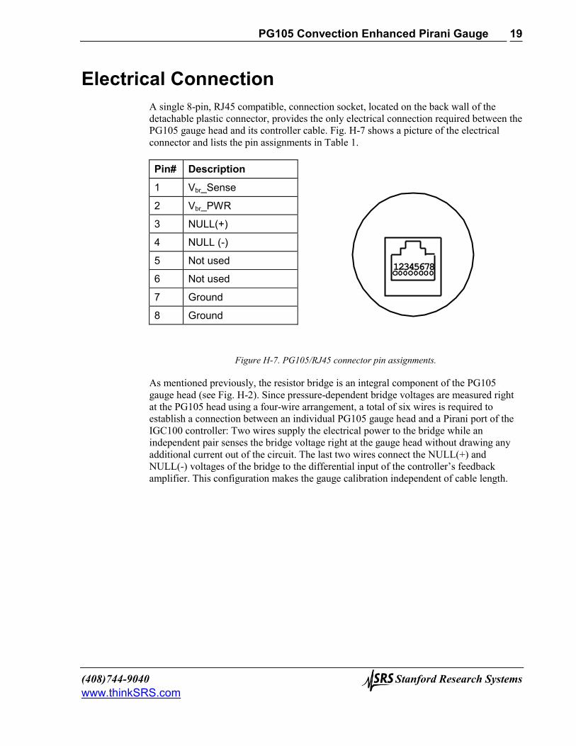
Electrical Connection A single 8-pin, RJ45 compatible, connection socket, located on the back wall of the detachable plastic connector, provides the only electrical connection required between the PG105 gauge head and its controller cable. Fig. H-7 shows a picture of the electrical connector and lists the pin assignments in Table 1.
Pin# Description
1 Vbr_Sense
2 Vbr_PWR
3 NULL(+)
4 NULL (-)
5 Not used
6 Not used
7 Ground
8 Ground
Figure H-7. PG105/RJ45 connector pin assignments.
As mentioned previously, the resistor bridge is an integral component of the PG105 gauge head (see Fig. H-2). Since pressure-dependent bridge voltages are measured right at the PG105 head using a four-wire arrangement, a total of six wires is required to establish a connection between an individual PG105 gauge head and a Pirani port of the IGC100 controller: Two wires supply the electrical power to the bridge while an independent pair senses the bridge voltage right at the gauge head without drawing any additional current out of the circuit. The last two wires connect the NULL(+) and NULL(-) voltages of the bridge to the differential input of the controller’s feedback amplifier. This configuration makes the gauge calibration independent of cable length.
12 3 4 5 6 7 8

PG105 Convection Enhanced Pirani Gauge
Stanford Research Systems (408)744-9040 www.thinkSRS.com
20
PG105 Gauge Test Procedure Breakage of the small diameter sensor wire located inside the tube is a common failure mechanism for all Pirani gauges. Fortunately it is very easy to test the PG105 gauges for electrical continuity, to determine the integrity of both the sensor and temperature compensation wires.
WARNING! Use an ohmmeter that cannot apply more than 0.1 V when the gauge is at vacuum or 2 V when at atmospheric pressure.
Figure H-8. Back view of the PG105 tube, with the plastic connector removed.
1. Disconnect the Detachable Plastic Connector from the PG105 gauge head. Four feedthru connector pins are now easily accessible from the back of the gauge tube as schematically represented in Fig. H-8.
2. Following the pin assignments of Fig. H-8, measure the resistance between pins 1 and 4 and between pins 2 and 3. The nominal wire resistances are:
Pins Wire Expected value (Ohms)
1 to 4 Sensor 20 – 22
2 to 3 Compensate 35 - 40 3. Gauge wires are not replaceable! Replace the gauge head if the wire resistance values
do not fall within the ranges specified above.
1 3
42

PG105 Convection Enhanced Pirani Gauge
(408)744-9040 Stanford Research Systems www.thinkSRS.com
21
References 1 Pirani, M., Deutsche Phys. Ges. 8 (1906) 686. The first report of the Pirani gauge by its inventor.
2 For one of the most complete discussions of Pirani Gauges consult: J.H. Leck, "Total and partial pressure measurement in vacuum systems", Chapter 2, titled "Thermal conductivity gauges", starting at page 39. Blackie & Son Ltd., Glasgow, England, 1989.
3 Two amplifier circuits are built into every IGC100 controller, to control up to two PG105 gauges simultaneously.
4 For theoretical derivations consult: J. M. Lafferty, "Foundations of vacuum science and technology", Wiley Interscience, 1998, NY, p. 404, section 6.8.1.
5 L. Heijne and A. T. Vink, "A Pirani gauge for pressures up to 1000 Torr and higher", Philips Technical Rev. 30 (1969) 166; see also: J. B. Johnson, "Convection Type Manometer", The Review of Scientific Instruments, 27(5) (1956) 303; and J. A. McMillan, et. al. "Wide Range Thermal Convection Manometer", The review of Scientific Instruments , 28(11) (1957) 881.
6 J. English, B. Fletcher and W. Steckelmacher, "A wide range constant-resistance Pirani gauge with ambient temperature compensation", J. Sci. Instrum. 42 (1965) 77; W. Steckelmacher and B. Fletcher, "Extension of range of thermal conductivity vacuum gauge to atmospheric pressure by natural convection", J. Phys. E, Sci. Instrum. 5 (1972) 405; W. Steckelmacher, "The high pressure sensitivity extension of thermal conductivity gauges", Vacuum 23 (9) (1973) 307.
7 Zero adjustment of the gauge should not be necessary unless readout accuracy is required below 1 mTorr or the gauge has been contaminated.
8 Consult R. E. Ellefson and A.P. Miller, "Recommended practice for calibrating vacuum gauges of the thermal conductivity type", J. Vac. Sci. Technol. A 18(5) (2000) 2568, for information on thermal gauge calibration and accuracy.
9 R.E. Ellefson, and A. P. Miller, "Recommended Practice for Calibrating Vacuum Gauges of the Thermal Conductivity Type", J. Vac. Sci. Technol. To be published sometime during the spring of the year 2000.
10 Vic Comello, "Simplify Rough Pumping With a Wide-Range Gauge", R&D Magazine, May 1999, p. 57.
11 See also U.S. patent #6,227,056 for more details.
12 K. F. Poulter, Mary-Jo Rodgers and K. W. Ascroft, "Reproducibility of the performance of Pirani Gauges", J. Vac. Sci. Technol. 17(2) (1980) 638.
13 McMillan, J. A. and Buch, T., Rev. Sci. Instr. 28 (1957) 881.
14 J. H. Leck, "The high temperature Pirani Gauge", J. Sci. Instr. 29 (1952) 258.
15 Consult the book by J. H. Leck mentioned above, p. 45, section 2.3.
PG105 Convection Enhanced Pirani Gauge
Stanford Research Systems (408)744-9040 www.thinkSRS.com
22
16 The accommodation coefficient provides a measure of the efficiency of energy transfer from the hot
wire to the gas molecules that collide with its surface. Its magnitude depends on (1) the gas, (2) the metal surface material, (3) contamination buildup on the wire surface, and (4) the temperatures involved. For more details consult: J.H. Leck, "Total and partial pressure measurement in vacuum systems", Chapter 2, titled "Thermal conductivity gauges", section 2.5., page 46. Blackie & Son Ltd., Glasgow, England.(1989).
17 Vic. Comello, "Using Thermal Conductivity Gauges", R&D Magazine, Vol. 38, Number 8, July 1997, p. 57. Useful article with application examples, and some tips.
18 Stephen Hansen, "Pressure measurement and control in loadlocks", Solid State Technology, October 1997, p. 151.
19 J. Blears and J. H. Leck, J. Sci. Instrum. 28, Suppl. 1, 20 (1951); W. Steckelmacher and D. M. Tinsley, Vacuum 12 (1962) 153; J. K. N. Sharma and A. C. Gupta, Vacuum 36 (1986) 279; C. C. Minter, Rev. Sci. Instrum. 29 (1958) 793.
20 R. N. Peacock, "Safety and health considerations related to vacuum gauging", J. Vac. Sci. Technol. A 11(4) (1993) 1627.
21 R. Chapman and J. P. Hobson, J. Vac. Sci. Technol. 16 (1979) 965, D. G. Bills, J. Vac. Sci. Technol. 16 (1979) 2109.