phase 2 ground investigation report for st …planningdocs.gloucester.gov.uk/webcache/802480/... ·...
TRANSCRIPT

36 Brunswick Road Gloucester GL1 1JJ
Report No. 3897/2
AG SASSOCIATION OF GEOTECHNICAL & GEOENVIRONMENTAL SPECIALISTS
Wilson Associates (Consulting) Limited
Registered O ice 36 Brunswick Road, Gloucester GL1 1JJ
Company No 6133365
PHASE 2 GROUND INVESTIGATION REPORT
FOR ST JAMES’ CLOSE, QUEDGELEY,
GLOUCESTER
PREPARED FOR GLOUCESTER CITY HOMES
Job No. 3897/2
Page No. ii
Report Production Record
Report No 3897/2
Site Name St James’ Close, Quedgeley, Gloucester
Client Gloucester City Homes
Report on Phase 2 Intrusive Investigation
Issue No. / Status 1 Final
Prepared by Timothy D Coe BSc(Hons) MSc FGS
Approved by David J Wilson BSc(Geol) CGeol FGS MIQ
Date 25 August 2015
Report Revision Record
Issue No. Date Revision Details
COPYRIGHT AND NON-DISCLOSURE NOTICE
The contents and layout of this report are subject to copyright owned by Wilson Associates (2015) save to the extent that copyright has been legally assigned by us to another party or is used by Wilson Associates under licence. To the extent that we own the copyright of this report, it may not be copied or used without our prior written agreement for any purpose other than the purpose indicated in this report. The methodology (if any) contained in this report is provided to you in confidence and must not be disclosed or copied to third parties without the prior written agreement of Wilson Associates. Disclosure of that information may constitute an actionable breach of confidence or may otherwise prejudice our commercial interests. Any third party who obtains access to this report by any means will, in any event, be subject to the Third Party Disclaimer set out below.
THIRD PARTY DISCLAIMER Any disclosure of this report to a third party is subject to this disclaimer. The report was prepared by Wilson Associates at the instruction of, and for use by, our client named on the front of the report. It does not in any way constitute advice to any third party who is able to access it by any means. Wilson Associates excludes to the fullest extent lawfully permitted all liability whatsoever for any loss or damage howsoever arising from reliance on the contents of this report. We do not however exclude our liability (if any) for personal injury or death resulting from our negligence, for fraud or any other matter in relation to which we cannot legally exclude liability. Legal re-assignment to another party can be arranged - please contact this Practice for further details.

Job No. 3897/2
Page No. iii
CONTENTS REPORT Page No. 1 INTRODUCTION 1
2 PROPOSED DEVELOPMENT 2
3 GROUND INVESTIGATION REPORT 2
Site Works 2 Laboratory Testing – Geotechnical 3 Laboratory Testing – Contamination 4 Discussion on Ground Conditions 5 Soakaway Feasibility 6
4 GEOTECHNICAL DESIGN REPORT 6
Foundation Design 7 Pavement Design 10 Soakaway Design 11 Recommendations for Monitoring During Construction 11 5 CONTAMINATION RISK ASSESSMENT AND SOIL WASTE CLASSIFICATION 11
Human Health 11 Water Supply Pipework 12 Landfill & Radon Gas 13 Controlled Waters 13 Remedial Options Appraisal 13 Waste Classification For Offsite Disposal Of Arisings 14 Caveats 15
6 REFINED CONCEPTUAL SITE MODEL 16 7 CONCLUSIONS AND RECOMMENDATIONS 17 8 REFERENCES 19
DRAWINGS No.
SITE LOCATION 3897/2//1 EXISTING SITE LAYOUT SHOWING INVESTIGATION LOCATIONS 3897/2/2 APPENDICES
1 CONTAMINATION STATUTORY FRAMEWORK/METHODOLOGY AND CERTIFIED CONTAMINATION TEST RESULTS
2 SITE PHOTOGRAPHS 3 BOREHOLE LOGS (INCLUDING PHOTOGRAPHS) 4 WASTE CLASSIFICATION WORKSHEET

Job No. 3897/2
Page No. 1
PHASE 2 GROUND INVESTIGATION REPORT FOR
ST JAMES’ CLOSE, QUEDGELEY, GLOUCESTER
PREPARED FOR GLOUCESTER CITY HOMES
1 INTRODUCTION 1.1 It is proposed to construct a residential development at the above site in the
Quedgeley district of Gloucester. A Phase 1 geo-environmental desk study was reported by this Practice under reference No. 3897 in July 2015 and to briefly summarise those findings, historical mapping suggests that the site has been at least partially developed since the earliest available mapping of 1884, with past site uses including residential dwellings and a depot. The preliminary Conceptual Site Model identified several potential pollutant linkages to future users as well as local receptors such as groundwater, most likely relating to the former depot, thus an intrusive Phase 2 investigation was recommended.
1.2 This report therefore comprises the result of Phase 2 intrusive investigation, the
primary objective of which was to ascertain the ground conditions for appropriate foundation, ground floor slab, external pavement and soakaway design. A preliminary quantitative contamination risk assessment with regard to potential impacts to human health and/or controlled waters has also been undertaken.
1.3 The geotechnical investigation has been carried out in general accordance with
Eurocode 7 ʻGeotechnical Designʻ, in particular BS EN 1997-1:2004 and 1997-2:2007 and BS EN ISO 14688-1:2002 and 14688-2:2004. The proposed development is considered to fall into the Geotechnical Category 2 classification, thus routine field and laboratory testing methods have been adopted. Reference has also been made to BS5930:2015 Code of Practice for Site Investigation, and National House Building Council (NHBC) Standards Chapter 4.2 – ʻBuilding Near Treesʼ.
1.4 The Geo-environmental assessment has been carried out in accordance with
BS10175:2011 “Code of Practice for the Investigation of Potentially Contaminated Sites” and EA document CLR 11 “Model Procedures for the Management of Land Contamination”.

Job No. 3897/2
Page No. 2
1.5 This report has been prepared in line with the agreed scope of works as set out
within our quotation TC/Q3897/2 dated 14 July 2015, with email instruction from Kelly Thomas of Gloucester City Homes, received 14 July 2015.
2 PROPOSED DEVELOPMENT 2.1 The site is to be redeveloped with a residential end use although no proposed
development layout or final ground levels were made available at the time of writing. 3 GROUND INVESTIGATION REPORT Site Works 3.1 The Phase 2 intrusive investigation took place on 27 July 2015 by windowless
sampling (small diameter) boreholes. The location of all exploratory hole positions were selected by this Practice in order to target any features highlighted by the desk study researches as well as obtain good coverage across the entire site. Positions were subsequently marked out on site (again by this Practice) using both on and off-site reference points, and are indicated on drawing 3897/2/2. As an added precaution, where possible nearby service covers were lifted to confirm service direction, a CAT electrical service scanner was deployed prior to all intrusive works and all positions were manually excavated up to 1.2m depth. No actual services (recorded or unrecorded) were encountered during the works.
3.2 A total of seven boreholes (WS1-WS7) were drilled to depths of up to 3.45m using a
Terrier 2002 window-sampling drilling rig. The boreholes were logged by a suitably qualified engineer from this Practice in accordance with Eurocode 7 (BS EN ISO 14688-1:2002 and 14688-2:2004), and representative disturbed samples taken for geotechnical and contamination testing as appropriate. In-situ standard penetration tests (SPT) were undertaken in accordance with BS EN ISO 22476-3:2005 to assess the relative density of the material penetrated and these results are indicated on the respective logs in Appendix 3.

Job No. 3897/2
Page No. 3
3.3 Preliminary percolation tests to assess ground suitability for the adoption of soakaway drains were performed as falling head tests in selected boreholes. Two individual tests were undertaken within boreholes WS1 and WS4, the results of which are presented with the respective logs in Appendix 3. The feasibility of soakaway system installation is discussed further in paragraphs 3.15-3.16 below. It should be recognised that these tests are not in strict accordance with the requirements of BRE 365 guidance and should be considered as a preliminary guide to soakaway potential only. It would be normal practice to base drain design upon the results of full-scale tests in trial pits, and with three tests undertaken per pit. This Practice would be happy to advise further and undertake such testing as required.
3.4 Upon completion of works, all boreholes were backfilled to surface using arisings
nominally compacted by hand and surface topsoil replaced. Laboratory Testing - Geotechnical 3.5 A number of disturbed samples were taken for routine geotechnical classification
testing, comprising moisture content and plasticity determinations, along with classification to the Unified Soil Classification Scheme (USCS) and NHBC Standards, plus acidity and sulphate analysis to BRE Special Digest 1 requirements. Results are tabulated below.
TABLE 1: INDEX TEST RESULTS AND CLASSIFICATION
BH No
Depth (m)
Samp e of
Mo sture Content
(%)
L qu d L m t (%)
P ast c L m t (%)
P ast c ty Index (%)
P ast c ty / USCS
Cons stency Index
<425um (%)
Mod f ed P ast c ty
Index (%)
Vo ume Change Potent a (NHBC)
WS1 1 5 CMF 23 67 21 46 CH 0 96 91 42 H gh
WS2 2 5 CMF 30 71 22 49 CV 0 84 98 48 H gh
WS3 0 6 CMF 27 60 19 41 CH 0 80 97 40 H gh
WS4 1 4 CMF 29 64 21 43 CH 0 81 98 42 H gh
WS5 0 9 CMF 22 64 21 43 CH 0 98 96 41 H gh
WS6 2 8 CMF 26 65 18 47 CH 0 83 97 46 H gh
WS7 1 2 CMF 24 61 20 41 CH 0 90 98 40 H gh
CMF = Charmouth Mudstone Formation

Job No. 3897/2
Page No. 4
TABLE 2: CHEMICAL TEST RESULTS AND CLASSIFICATION
BH No
Depth (m)
Samp e of
Tota su phate
SO4 (%)
Tota su phur
(%)
Tota potent a su phate
SO4 (%)
Ox d sab e Su ph des
SO4 (%)
pH va ue n so
Water so ub e
su phate SO4
(mg/ )
Des gn Su phate
C ass
Aggress ve Chem ca Concrete
C ass
WS1 1 5 CMF 6 2 2 1 6 3 0 10 7 7 1500 DS-3 AC-3
WS2 2 5 CMF 4 8 1 7 3 2 <0 01 7 5 1000 DS-4 AC-4
WS3 0 6 CMF 0 16 0 07 0 21 0 05 8 1 <50 DS-1 AC-1
WS4 1 4 CMF 0 05 <0 05 <0 15 <0 10 7 8 83 DS-1 AC-1
WS6 0 9 CMF 0 04 <0 05 <0 15 <0 11 8 0 <50 DS-1 AC-1
WS6 2 8 CMF 2 8 0 85 2 5 <0 01 8 1 1200 DS-3 AC-3
WS7 1 2 CMF 0 08 <0 05 <0 15 0 07 7 8 <50 DS-1 AC-1
CMF = Charmouth Mudstone Formation
Laboratory Testing - Contamination
3.6 The contamination sampling scheme was conducted in accordance with BS10175:2011, with the former depot targeted and all other sampling positions ʻnon-targetedʼ to provide general spatial coverage across the rest of the site.
3.7 Representative samples of made ground and natural undisturbed soil were taken
from the upper 1.0m of extracted ground. Those soils to be scheduled for organic analysis were sealed within amber glass jars to prevent loss of any volatiles during transit, whilst those for inorganic testing were placed in plastic tubs, all with chain of custody labelling. Samples were sent to UKAS accredited Scientific Analysis Laboratories in Manchester where analysis selectively comprised the following: • Toxic and phytotoxic metals
• pH
• Soil organic matter content
• Speciated polyaromatic hydrocarbons (PAH)
• Total petroleum hydrocarbons (TPH) (carbon range – C8-35)
3.8 The potential risk to groundwater resources was determined by leachate analysis of three representative samples of topsoil and natural CMF, with samples tested to

Job No. 3897/2
Page No. 5
determine the leachable content of toxic and phytotoxic metals and polyaromatic hydrocarbons.
3.9 The certified laboratory test results are presented as Appendix 1 and for
convenience these have also been summarised to facilitate comparison against assessment criteria. All results and their implications upon the preliminary CSM (as previously reported in WA report ref 3897) are further discussed in Sections 5 and 6.
Discussion On Ground Conditions
3.10 Ground conditions appear to be commensurate with geological mapping. Beneath a thin mantle of topsoil and/or hardstand and localised made ground, all boreholes encountered plastic clay, representing the upper weathered zone of the recorded Charmouth Mudstone Formation. A summary of all the observed strata is presented in Table 3 below.
TABLE 3: SUMMARY OF OBSERVED STRATA
Stratum Base Depth (m)
Notes
TOPSOIL: probab e f rm to st ff m d grey/dark brown organ c oca y sandy des ccated CLAY w th rare to occas ona coarse sand to f ne grave of charcoa and br ck p us many roots from over y ng grass
0 15-0 25 Encountered n a boreho es
MADE GROUND: most y recovered as probab e f rm dark brown sandy fr ab e CLAY w th rare f ne grave of br ck and charcoa and oca y w th cobb es of concrete
0 48-0 80 Encountered n
boreho es WS2-5 and WS7
CLAY: f rm grey p ast c CLAY often recovered w th many gypsum crysta s W th ncreas ng depth becom ng st ff and show ng a re ct mudstone fabr c Charmouth Mudstone Formation
>3 45 Encountered n
a boreho es to term na depth
Roots
Live Root Depth
(m) WS1 1 5m WS2 1 4m WS3 0 9m WS4 0 7m WS5 1 5m WS6 1 1m WS7 1 4m
Relict Root Depth
(m) WS1 1 9m
WS2 >3 45m WS3 1 7m WS4 2 2m WS5 2 0m WS6 2 4m WS7 1 9m
Perched/Groundwater A boreho es dry dur ng t me eft open

Job No. 3897/2
Page No. 6
3.11 Based upon on-site visual and olfactory examination of arisings there was nothing
encountered within boreholes to suggest the presence of obviously significantly contaminated subsoil, although it is recognised that the variability of near surface made ground poses a possible risk of elevated contaminants.
3.12 The underlying CMF is entirely cohesive in composition and index testing classifies
this undisturbed material as inorganic clay of high to very high plasticity and high volume change potential in accordance with NHBC Standards. Consistency index (CI) values range between 0.80 and 0.98 suggesting that the clay is normally hydrated, and our visual assessment confirms an apparent absence of current desiccation.
3.13 Water was not struck in any borehole and all remained dry during the length of time
that they remained open. The groundwater level is of course subject to seasonal fluctuation according to prevailing weather conditions, and the situation encountered and described above could potentially change in the future, especially in a period of seemingly ever-apparent but unpredictable climate change.
Soakaway Feasibility 3.14 Two percolation tests were undertaken as falling head tests within boreholes WS1
and WS4 with test zone depths of between 0.51m and 3.45m and testing periods of between 158 and 326 minutes.
3.15 Both tests recorded insufficient (negligible) water drainage to enable calculation of a
soil infiltration rate. It is considered that the cohesive geology beneath the entire site will not permit infiltration and would therefore appear to be unsuitable for the installation of a soakaway (SuDS) drainage system. This is consistent with our previous experience of testing within CMF material
4 GEOTECHNICAL DESIGN REPORT 4.1 The site investigation works achieved by the drilling of seven boreholes have proven
ground conditions beneath the site to be in accordance with recorded mapping. Beneath surface topsoil/hardstand and made ground deposits, clay representing the

Job No. 3897/2
Page No. 7
upper weathered zone of the recorded Charmouth Mudstone Group was encountered to terminal depth in all boreholes.
Foundation Design 4.2 The natural weathered soils of the CMF were identified as entirely cohesive, which
laboratory index test results have classified as being of high volume change potential, therefore (following NHBC guidance) a minimum foundation depth of 1.0m is required, or greater within the radius of influence of trees and obviously subject to those foundations also penetrating through any localised softer or disturbed deposits (including all made ground etc) to found in undisturbed natural material.
4.3 Consideration has been given as to whether any additional foundation deepening is
required (beyond the above recommendation) to account for potential tree root activity and site observations indicate that there are many trees located in and immediately surrounding the site. It is recommended that plot-specific foundation depths are calculated for those plots potentially affected by future root growth once a final proposed development layout is made available. Given the high volume change potential of the near surface subsoil, heave protection will be required.
4.4 It is assumed that strip foundations are likely to be the favoured foundation option
and the following is based on a 0.6m width foundation at minimum 1.0m depth and an assumed line load of 45kN/m run (allowing for suspended ground floor slabs).
4.5 Design calculations in Eurocode 7 (BS EN 1997-1) require the establishment of
design values for actions, ground properties and ground resistances, definition of the limits that must not be exceeded (usually a serviceability limit state), the setting up of calculation models for the relevant ultimate or serviceability limit state, and showing by such calculation that these limits will not be exceeded. Design values for such calculations are derived by applying partial factors to characteristic values for actions, ground properties and ground resistances, and based upon the foregoing geotechnical model and following the requirements of Design Approach 1, both Combination 1 and Combination 2 calculations have been undertaken. Calculation sheets can be presented upon request.
4.6 BS EN 1997-2:2007 and BS EN ISO 22475-1:2006 require quality class 1 samples
for determination of soil shear strength, and such samples can only be obtained by category A sampling methods. To avoid the costly complexities of such sampling in-

Job No. 3897/2
Page No. 8
situ tests can alternatively be undertaken, the borehole standard penetration test (SPT) being the most commonly adopted method. Field results are adjusted or ʻnormalisedʼ in accordance with Eurocode requirements (BS EN ISO 22476-9:2009), to enable the generation of characteristic values of undrained shear strength that can then be used for determination of bearing resistance as described above.
4.7 The results of the insitu SPTʼs are shown in Table 4 below and the normalised ʻNʼ
values shown are also presented as N60 versus depth in Figure 1. Undrained shear strength has subsequently been calculated which also takes account of plasticity index values.
TABLE 4: SUMMARY OF SPT RESULTS
Borehole No.
Penetration below existing ground level (m)
Charmouth Mudstone Formation
Recorded insitu N Value
(uncorrected)
N60 (corrected)
WS1 1.2 2.0 3.0
31 18 26
35 20 29
WS2 1.2 2.0 3.0
10 13 25
11 14 28
WS3 1.2 2.0 3.0
10 11 22
11 12 24
WS4 1.2 2.0 3.0
3 2
20
3 2
22
WS5 1.2 2.0 3.0
11 11 25
12 12 28
WS6 1.2 2.0 3.0
14 21 29
16 23 32
WS7 1.2 2.0 3.0
13 12 19
14 13 21

Job No. 3897/2
Page No. 9
FIG 1: SPT ʻN60ʼ VALUES -v- DEPTH
4.8 Taking a characteristic SPT N60 value of 8 at 1.0m depth, based on work by Stroud and Butler utilising plasticity index, the N60 of 8 equates to an undrained shear strength (Cu) value of 32kN/m2. Based on the foregoing the bearing resistance has been calculated to be approximately 83kN/m2, which exceeds the estimated bearing pressure indicating suitability. It should be noted that low SPT N values were recorded within borehole WS4 at 1.2m and 2.0m depths (compared with that recorded in all other boreholes). It is not immediately apparent why such low N values were recorded, particularly as no water was struck and arisings appeared similar to material recorded at similar depths elsewhere on site. Indeed hand shear vane testing undertaken on the recovered core did not suggest a ʻsoftʼ clay. Further investigation may be necessary within the vicinity of borehole WS4 to clarify and determine the extent of such soft clay (subject to proposed layout). Design bearing resistance is plotted against depth in Figure 2 below, so that values can be assigned to alternative founding depths as necessary.
Characteristic Value Line

Job No. 3897/2
Page No. 10
FIG 2: DESIGN BEARING RESISTANCE -v- DEPTH
4.9 Those dwellings located within the zone of influence of one or more trees will require
suspended ground floor slabs, which should incorporate a subfloor void of 150mm for insitu concrete, 225mm for a pre-cast concrete floor or 300mm for a suspended timber floor.
4.10 In view of the results of the acidity and soluble sulphate testing, buried concrete in
spread foundations up to 1.4m depth can be constructed with a classification of Design Sulphate Class DS-1 and Aggressive Chemical (AC) Class AC-1 in accordance with BRE Special Digest 1 (2005). For spread foundations exceeding this depth concrete design will need to be increased to DS-3 and AC-3.
4.11 Foundation excavations should remain stable and in the short term it is not
anticipated that groundwater will be encountered down to proposed founding depths. As always groundwater levels may vary seasonally, and may therefore be encountered at levels in variance to those recorded by this investigation.
Pavement Design 4.12 With regard to pavement design for external hardstand, a near surface plasticity
index value of 41% within the cohesive clay suggests a California Bearing Ratio (CBR) of approximately 2.5-3% at a 0.6m depth horizon. As always it is recommended that insitu testing be carried out closer to the time of construction to

Job No. 3897/2
Page No. 11
obtain a more accurate bearing ratio. The clay soil is not considered to be frost-susceptible, however the Local Authority should be able to advise based upon their previous experience in the area.
Soakaway Design
4.13 The results of the percolation tests suggest that the soils found beneath the site are
of inadequate permeability to be suitable for a soakaway (SUDS) drainage system, therefore an alternative method of stormwater removal will be required.
Recommendations for Monitoring of Ground Conditions During Construction 4.14 In view of the importance of founding on natural ground, a careful watch must be
maintained during all foundation excavations to ensure that this requirement has been satisfied. As previously discussed, the extent of soft clay recorded within borehole WS4 may also need to be determined (subject to proposed development layout).
4.15 Consideration should be given to access into/around the site since the surface soils
have the potential to be subject to softening during periods of sustained wet weather. 4.16 Due to the potential for cohesive soils to shrink and swell, inspection during
foundation excavations should ensure that no live roots or evidence of desiccation is visible at the founding horizon.
4.17 In the event of any doubt in the above matters, this Practice would be pleased to
attend site as instructed. 5 CONTAMINATION RISK ASSESSMENT AND SOIL WASTE
CLASSIFICATION Human Health 5.1 The contamination risk assessment has been carried out in general accordance with
the methodology described within Appendix 1. This has comprised testing of near-surface soils to assess their suitability for incorporation or retention into the

Job No. 3897/2
Page No. 12
development proposal. In view of the nature of the proposals Tier 1 risk modelling has adopted the ʻresidentialʼ land use scenario, including the pathway of direct ingestion via vegetables grown for consumption, and the ʻcritical receptorʼ is taken as a female resident of age class 1-6.
5.2 It will be seen from the laboratory test result summary sheet in Appendix 1 that there
were no exceedances of phytotoxic metals, TPH or PAH compounds above their respective Tier 1 GAC/SGV. Of all the samples tested, only three samples including both topsoil and made ground recorded elevated levels of either the toxic metal arsenic or lead.
5.3 Regarding arsenic, a value of 38mg/kg was recorded within near surface made
ground (WS4/0.3m) which very mildly exceeds the Tier 1 C4SL of 37mg/kg. Progression has been made to a Tier 2 site-specific assessment where statistical analysis using the CIEH statistical calculator has been used to determine an upper confidence limit (UCL) of 22mg/kg. Given that the UCL is lower than the C4SL this suggests that the arsenic within the subsoil does not present a risk that significant possibility of significant harm can occur to future site users, and that preconstruction mitigation/remedial action is not necessary to protect human health from arsenic contamination.
5.4 Regarding lead, values of 230mg/kg and 290mg/kg were recorded within near
surface topsoil and made ground (WS5/0.3m and WS6/0.2m respectively), both of which mildly exceed the Tier 1 C4SL of 200mg/kg. Usually progression is made to a Tier 2 site specific assessment using CLEA v1.06, however this is not possible for lead as this particular metal was never included by the EA and therefore recommendations have been made based upon Tier 1 criteria only, although a Tier 1 SGV of 450mg/kg has for many years been widely adopted. The results currently suggest that the near surface topsoil and made ground within the western half of the site is locally contaminated and that remedial action may be necessary dependent upon the proposed development layout. A remedial options appraisal has been discussed in more detail in Section 5.9-5.12.
Water Supply Pipework
5.5 In addition to the above, consideration has been given to the potential effects of
recorded concentrations on new water utility pipework. Given the absence of organic contaminants there ought to be no requirement for upgraded barrier pipework and

Job No. 3897/2
Page No. 13
the results of the contamination testing undertaken as part of this investigation would seem to support this. As always it is recommended that advice be sought from the local regulatory authority prior to ordering, since it is possible that their specific in-house thresholds may differ markedly from those within the most recent guidance by UK Water Industry Research (UKWIR) report “Guidance for the Selection of Water Supply Pipes to be used in Brownfield Sites” (2010). Once the development layout is known further testing of samples taken along the route of the incoming mains supply pipe would be prudent.
Landfill Gas and Radon Gas 5.6 It was previously established in the desk study researches that the site is not located
within influencing distance of active/closed landfill sites. The boreholes have since found no evidence of methanogenic material beneath the site and landfill gas protection measures are not therefore considered necessary within new development.
5.7 Consultation of the BRE Report BR211 “Radon: guidance on protective measures for
new buildings” (2007) suggests that no radon protection measures are required in new development at this site.
Controlled Waters 5.8 The risk to groundwater has been assessed by leachate analysis on representative
samples of topsoil and CMF, with samples selectively tested to determine the leachable content of toxic and phytotoxic metals, TPH and speciated PAH. It will be seen within Appendix 1 that there are no elevations above respective groundwater threshold values and on this basis it is considered that there is a low potential risk, and pre-construction remedial action to protect controlled waters/groundwater resources should not be necessary.
Remedial Options Appraisal 5.9 The application of a clean cover system placed above the contaminated topsoil has
been considered, with the intention of preventing or reducing human contact with the contaminated material. Given the recorded lead values of 230-290mg/kg, it is recommended that a clean cover system will need to be a minimum thickness of 284mm. In the absence of proposed final ground levels it is unclear at this stage

Job No. 3897/2
Page No. 14
whether the foregoing could be accommodated within the proposed development without the need for prior removal of ground.
5.10 The option of commissioning the laboratory to undertake bio-accessibility testing
on the contaminated soil has been considered, which rather than preventing or reducing human contact with the contaminated material instead looks to determine the fraction of the elevated contaminants that could be realistically absorbed by the human body, thereby potentially reducing the result to an acceptable level and permitting soils to remain insitu.
5.11 The option of soil removal has been considered, which as for the clean cover
system also has the intention of preventing or reducing human contact with the contaminated material. The contaminated topsoil will require removal from those areas of the site proposed as gardens or soft landscaping. Proposed final ground levels have not been provided prior to submission of this report so it is not clear whether the option of retaining contaminated soil on site could be accommodated within the development if placed beneath future building/hardstand. Should off-site disposal of this material be considered then the recommendations within Section 5.13-5.14 will apply.
5.12 Based on the above we recommend that bio-accessibility testing is undertaken with
the intention of potentially reducing the results to an acceptable level below the C4SL threshold and permit soils to remain insitu.
Waste Classification for Off-Site Disposal of Arisings
5.13 In accordance with current legislation all soil arisings generated for disposal as part
of this development site are by definition a "commercial waste" and will be classified as both a directive and a controlled waste. Should it be necessary to remove from site any surplus excavation arisings (topsoil or natural ground) then as per the European Waste Catalogue (EWC) these will be coded 1705, that is "soil (including excavated soil from contaminated sites), stones and dredging spoil".
5.14 In accordance with Technical Guidance Waste Management 2 (TGWM2, EA Version
3.0, May 2013) the contamination test results obtained for that material have been compared with respective threshold data as set out in TGWM2 in order that this specific waste stream In accordance with Technical Guidance Waste Management 2 (TGWM2, EA Version 3.0, May 2013) the contamination test results obtained for that

Job No. 3897/2
Page No. 15
material have been compared with respective threshold data as set out in TGWM2 in order that this specific waste stream can be classified. As shown in Appendix 4, this material would be classified as a "Non-hazardous Mirror Entry" under EWC Code 170504 (soil and stones that do not contain the tested dangerous substances above the respective threshold value). Such materials can therefore be disposed of at a suitably licensed "non-hazardous" landfill site, which will require the contamination test data undertaken as part of this investigation. Should you wish to consider disposal as inert waste (at a lower tipping rate) then Waste Acceptance Criteria (WAC) testing will also be necessary.
Caveats 5.15 In line with best industry practice the scope of contamination testing has been based
upon the site history, current land usage and actual findings, with reference where necessary to DoE Industry Profiles and DEFRA/EA guidance. To the best of our knowledge information concerning the land quality assessment is accurate at the date of issue, however subsurface conditions including ground contamination may vary spatially and with time. There may be conditions pertaining to the site not disclosed by the above sources of information, which might have a bearing upon the recommendations made, were such conditions known. We have however used our professional judgement in order to limit this during the investigation.
5.16 The conclusions and recommendations made in respect of land quality do not
address any potential risks to site operatives or ground workers during the construction stage. These issues should be addressed by the Principal Contractor in accordance with the relevant statutory procedures and regulations (CDM Regulations 2015).
5.17 It is important that these limitations be clearly recognised when the findings and
recommendations of this report are being interpreted. Additional assessment may be necessary should a significant delay occur between report date and implementation of the proposed scheme to which it relates.

Job No. 3897/2
Page No. 16
6 REFINED CONCEPTUAL SITE MODEL 6.1 In view of the above discussions the preliminary Conceptual Site model has been
refined as shown in Figure 3 and Table 5 below.
FIG 3: REFINED CONCEPTUAL SITE MODEL (NTS)
?
adjacentresidentialdwellings
proposedresidential
development
siteboundary
siteboundary
Topsoil/Made Ground
Charmouth MudstoneFormationS2
R1
R2
R3
P1P2
P3R5
R6
P2
P2R1
S1
TABLE 5: SUMMARY OF POTENTIAL / IDENTIFIED POLLUTANT LINKAGES
Ident f ed Sources Pathways Receptors
Comments Ref ned R sk Rat ng
Remed a / M t gat on Requ rements R1 R2 R3 R4 R5 R6
ON-SITE
S1
P1 X
Loca sed e evat on of the tox c meta ead (r sk greatest n proposed
gardens and soft andscaped POS)
Low
B o-access b ty test ng recommended to
m n m se/negate m t gat on measures adopted
P2 X X
P3
P4
P5
P6
P7
S2
P1
E evated su phate dent f ed w th n CMF h gh
Increased su phate protect on (DS-3 AC-3) necessary for
concrete foundat ons >1 4m depth
P2
P3
P4
P5 X
P6
P7
OFF-SITE
NONE
SOURCES S1 Loca sed e evat on of the tox c meta ead n topso and made ground
S2 Natura y e evated su phates n c ay
PATHWAYS
P1 D rect derma contact or ngest on v a so attached to vegetab es
P2 Inha at on of dust & vapours
P3 Permeat on nto new water supp y p pework
P4 Vert ca each ng of eachab e contam nants n unsaturated zone and atera m grat on n saturated zone
P5 D rect contact w th h gh su phate-bear ng c ay
P6 Landf gas m grat on through unsaturated zone and accumu at on w th n conf ned spaces
P7 Radon gas m grat on through unsaturated zone and accumu at on w th n conf ned spaces
RECEPTORS
R1 Future s te users (cr t ca user s fema e ch d age c ass 1-6)
R2 Potab e water supp y
R3 Groundwater (CMF s Secondary Und fferent ated aqu fer)
R4 Surface waters
R5 Concrete foundat ons
R6 Adjacent s te users

Job No. 3897/2
Page No. 17
7 CONCLUSIONS AND RECOMMENDATIONS
7.1 The foregoing discussions and recommendations are based upon the results of a geo-environmental desk study (as reported separately under WA ref 3897), followed by intrusive ground investigation comprising boreholes plus insitu testing and laboratory geotechnical and contamination testing. The boreholes appear to present a consistent pattern of subsoil conditions concordant with recorded geological mapping, comprising solid Charmouth Mudstone Formation beneath a thin veneer of superficial topsoil and made ground. As always a careful watch should be maintained for any anomalous conditions during site stripping and excavation, which should be reported back to this Practice for further investigation and assessment.
7.2 The intrusive investigation has proven a surface mantle of topsoil and made ground
up 0.8m depth, beneath which is the recorded undisturbed solid Charmouth Mudstone Formation, encountered as firm to stiff, plastic CLAY, with crystalline gypsum and locally containing live roots with evidence of relict desiccation. All boreholes remained dry and stable during the time that they were left open and it is not anticipated that the short-term stability of new foundation trenches will be affected.
7.3 Foundations will need to penetrate any near surface disturbed, softer or desiccated
ground to found within normally hydrated soil of the undisturbed Charmouth Mudstone Formation. Obviously subject to specific development details it is currently considered that conventional 0.45/0.6m wide strip foundations ought to be appropriate with deepening and heave protection required for those plots in proximity to existing trees. Suspended ground floor slabs will be required for buildings within the zone of influence of trees.
7.4 Buried concrete in spread foundations up to 1.4m depth can be constructed to
Design Sulphate Class DS-1 and Aggressive Chemical (AC) Class AC-1 in accordance with BRE Special Digest 1 (2005). For spread foundations exceeding this depth concrete design will need to be increased to DS-4 and AC-4.
7.5 In terms of proposed access roads a correlated CBR value of 2.5-3% has been
determined for the near surface clay. As always it is recommended that in-situ tests be undertaken closer to the time of construction.

Job No. 3897/2
Page No. 18
7.6 The soils found beneath the entire site are of inadequate permeability to be suitable for a soakaway (SUDS) drainage system, therefore an alternative method of surface-water removal will be required.
7.7 Contamination risk assessment has shown near-surface topsoil to be locally mildly
contaminated with the toxic metal lead, which poses a potential risk in terms of human health. Further assessment in the form of bio-accessibility testing is recommended to potentially reduce results to an acceptable level thereby permitting soils to remain insitu. Should off-site disposal of this material be considered, results to date suggest a "Non-hazardous Mirror Entry" (EWC Code 17-05-04) classification, therefore such materials can be disposed of at a suitably licensed "non-hazardous" landfill site. Note that WAC testing will be required if disposal as inert waste were to be considered.
7.8 There is no requirement for landfill gas protection measures, and in line with BRE
guidance, no radon protection measures are necessary within new construction at this site.
7.9 As ever a careful watch should be maintained during construction excavations in
case unexpected contamination may be exposed, in which case this Practice should be informed such that appropriate further assessment can be arranged.
7.10 Should planning consent be subject to certain conditions, this report and attachments
should be lodged with the local planning authority, such that they can update their records.
7.11 The above recommendations must not be used in respect of any development
differing in any way from the proposals described in this report, without reference back to this Practice or to another geotechnical specialist. This report is subject to our standard terms and conditions.

Job No. 3897/2
Page No. 19
8 REFERENCES
Geotechnical
BS EN 1997-1:2004 Geotechn ca Des gn - General Rulesʼ
BS EN 1997-2:2007 Geotechn ca Des gn - Ground Investigation & Testingʼ
Br t sh Standards Inst tute BS5930: 2015 Code of Practice of Site Investigations (2015)
Nat ona House Bu d ng Counc (NHBC) Standards: Chapter 4 2 Building Near Trees (2014)
BS EN 14688: ʻGeotechnical Investigation and Testing - Identification and Classification of Soil Part 1 Identification and Description (2002)
BS EN 14688: ʻGeotechnical Investigation and Testing - Identification and Classification of Soil Part 2 Principles for a Classificationʼ (2004)
BS EN 14689: ʻGeotechnical Investigation and Testing - Identification and Classification of Rock Part 1 Identification and Description (2003)
Br t sh Standards Inst tute BS 1377: ʻBritish Standard Methods of Test for Soils for Civil Engineering Purposesʼ, Parts 1 - 9 (1990)
H ghways Agency Inter m Adv ce Note 73/06 Rev 1 (2009) Des gn Gu dance for Road Pavement Foundat ons
Bu d ng Research Estab shment (BRE) Spec a D gest 1 Concrete in Aggressive Ground (2005)
Br t sh Geo og ca Survey (Eng and & Wa es) Sheet SO 81 SW (1975)
Bu d ng Research Estab shment (BRE) D gest 365 “Soakaway Design” (2007)
Department of Transport Ser es 600: Spec f cat on for Earthworks (1991)
Environmental
Br t sh Standards Inst tute BS 10175: ʻCode of Practice for the Investigation of Potentially Contaminated Sitesʼ (2011)
Env ronment Agency CLR 11: Model Procedures for the Management of Land Contamination
Env ronment Agency/Nat ona House Bu d ng Counc (NHBC) R&D 66 Gu dance for the Safe Deve opment of Hous ng on Land Affected by Contam nat on (2000)
Chartered Inst tute of Env ronmenta Hea th (CIEH)/Land Qua ty Management L m ted (LQM) The LQM/CIEH ʻGeneric Assessment Criteria for Human Health Risk Assessmentʼ (2nd Ed t on) Land Qua ty Press
Department of the Env ronment Transport & the Reg ons: ʻThe Environmental Protection Act 1990: Part IIAʼ (2000)
Construct on Industry Research & Informat on Assoc at on (CIRIA) 665: Assessing Risks Posed by Hazardous Ground Gases to Buildings (2007)
Bu d ng Research Estab shment (BRE): Radon Guidance on Protective Measures for New Buildings (2007)
Env ronment Agency: The R ver Bas n D str cts Typo ogy Standards & Groundwater thresho d va ues (Water Framework D rect ve) (Eng and & Wa es) D rect ons (2010)
The Water Supp y (Water Qua ty) Regu at ons 2000 (Amendment) Regu at ons (2007)
UK Water Industry Research L m ted (UKWIR) Gu dance for the Se ect on of Water Supp y P pes to be used n Brownf e d S tes (2010)
Techn ca Gu dance Waste Management 2 (TGWM2 EA Vers on 3 0 May 2013)
Bu d ng Research Estab shment (BRE)- Cover Systems for Land Regenerat on (2004)
Landmark H stor ca Mapp ng (Report No 68493069 1 1) 10 June 2015
Env ronment Agency (www env ronment-agency gov uk)
Hea th Protect on Agency (www hpa org uk)
Zet ca (www zet ca com)
Prev ous WA Phase 1 Geo-Env ronmenta Desk Study Report Ref: 3897 (10 Ju y 2015)

ST JAMES CLOSE, QUEDGELEY, GLOUCESTER GL2 4PL
SITE LOCATION (based on Microsoft Bing Mapping)
Drawing No.Job No. Scale: Date:3897/2 3897/2/1 NTS 18-08-15
THESITENN
Quedgeley

NN
P1
Number anddirection ofphotograph
(Appendix 2)
ST JAMES’ CLOSE, QUEDGELEY, GLOUCESTER
EXISTING SITE LAYOUT (based upon Quattro Design Architects drg. 3175/F/06, May 2015) SHOWING SITE WALKOVER ANNOTATIONS AND INVESTIGATION LOCATIONS
Drawing No.Job No. Scale: Date:3897/2 3897/2/2 1:500 18-08-15
willow 3N
o. (7
m)
Tesco Supermarket
SupermarketCar Park
St James’Church Yard
SCHOOL LANE
ResidentialBungalows
Grass
hawtho
rn (7
m)
copp
er be
ech (
7m)
copp
er be
ech (
8m)
hedgerow includinghawthorn (8m)
hawthorn (10m)
white willow(fallen)
hawthorn hedgerow
(4-5m)
hawthorn(5m)
elder (3m) conifer 2No.(10m)
pollardedcrack willow
stump
P1
P2
P5
P4
conifer(1m)
(8m)
elder (5m)
elder (5m)
(8m)
rowan (7m)
P3
WS1
WS2
WS3
WS4
WS5
WS6
WS7

Job No. 3897/2
APPENDIX 1
CONTAMINATION
STATUTORY FRAMEWORK / METHODOLOGY AND
CERTIFIED CONTAMINATION TEST RESULTS

Job No. 3897/2
Page No. 1 A1 CONTAMINATION RISK ASSESSMENT Statutory Framework A1.1 Part 2A of the Environmental Protection Act 1990 (inserted by Section 57 of the
Environment Act 1995) provides a regime for the control of specific threats to health or the environment from existing land contamination. In accordance with the Act and the statutory guidance document on the Contaminated Land (England) Regulations 2000, the definition of contaminated land is intended to embody the concept of risk assessment. Within the meaning of the Act, land is only ʼcontaminated landʼ where it appears to the regulatory authority, by reason of substances within or under the land, that:
• Significant harm is being caused or there is significant possibility of such harm
being caused; or • Pollution of controlled waters is being, or is likely to be, caused.
A1.2 In 2012 revised Statutory Guidance for Part 2A of the Environmental Protection Act
(1990) came into force for England and Wales. This introduced a new four category approach for classifying land affected by contamination to assist decisions by regulators in cases of Significant Possibility of Significant Harm (SPOSH) to specified receptors, including humans, and significant pollution of controlled waters.
Category 1 describes land which is clearly problematic e.g. because similar sites are known to have caused a significant problem in the past. The legal definition is where “there is an unacceptably high probability, supported by robust science-based evidence, that significant harm would occur if no action is taken to stop it”. Categories 2 and 3 cover land where detailed consideration is needed before deciding whether it may be contaminated land. Category 2 is defined as land where “there is a strong case for considering that the risks from the land are of sufficient concern that the land poses a significant possibility of significant harm”. Category 3 is defined as land where there is not the strong case described in the test for Category 2, and may include “land where the risks are not low, but nonetheless the authority considers that regulatory intervention under Part 2A is not warranted”. The decision basis is initially related to human health risks, and if this is not conclusive due to uncertainty over risks, wider socio-economic factors (e.g. cost, local perception etc).

Job No. 3897/2
Page No. 2
Category 4 describes land that is clearly not contaminated land, where there is no risk or the level or risk posed is low. This same 4 category system has also been introduced to assist in identifying whether there is a significant possibility of significant pollution of controlled waters. Part 2A states that normal levels of contaminants in soil should not be considered to cause land to qualify as contaminated land, unless there is a particular reason to consider otherwise. Following publication of the revised Statutory Guidance, DEFRA commissioned a research project to develop new Category 4 Screening Levels (C4SLs) to provide a simplified test for regulators to aid decision-making on when land was suitable for use and definitely not contaminated land under the statutory regime. The output from this research project was published by CL:AIRE in December 2013, with Policy Companion Documents published in England by DEFRA in March 2014 and the Welsh Government in May 2014. The culmination of this work was the development of a framework and methodology for deriving C4SLs and the publication of final C4SLs for use as new screening values for six common contaminants.
Once land has been determined as contaminated land, the enforcing authority must consider how it should be remediated and, where appropriate, it must issue a remediation notice to require such remediation. The enforcing authority for the purposes of remediation may be the local authority which determined the land, or the Environment Agency which takes on responsibility once land has been determined if the land is deemed to be a “special site”. The rules on what land is to be regarded as special sites, and various rules on the issuing of remediation notices, are set out in the Contaminated Land (England) Regulations 2006
A1.2 The UK guidance on the assessment of land contamination has developed as a
direct result of the introduction of the above two Acts. The technical guidance supporting the new legislation has been summarised in a number of key documents collectively known as the Contaminated Land Reports (CLRs), a proposed series of twelve documents. Seven were originally published in March 1994, four more were published in April 2002, while the last remaining guidance document (CLR 11 was published in 2004. In 2008 CLR reports 7 to 10 were withdrawn by the Department of Environment Food & Rural Affairs and the Environment Agency and updated versions of CLR 9 and 10 were produced in the form of Science Reports SR2 and SR3.

Job No. 3897/2
Page No. 3 A1.3 The guidance defines ʻriskʼ as the combination of:
• The probability, or frequency, of occurrence of a defined hazard (e.g. exposure of a property to a substance with the potential to cause harm); and
• The magnitude (including the seriousness) of the consequences. A1.4 For a risk of pollution or environmental harm to occur as a result of ground
contamination, all of the following elements must be present:
• A source, i.e. a substance that is capable of causing pollution or harm;
• A pathway, i.e. a route by which the contaminant can reach the receptor; and
• A receptor (or target), i.e. something which could be adversely affected by the contaminant.
A1.5 If any one of these elements is missing there can be no significant risk. If all are
present then the magnitude of the risk is a function of the magnitude and mobility of the source, the sensitivity of the receptor and the nature of the migration pathway.
A1.6 The presence of contamination is also a material issue in the determination of
planning applications, and where a change of use is proposed, especially on brownfield (former industrial) land, investigation, assessment and remediation of contamination is often a requirement of the Planning Authority. The presence of contamination may consequently require remedial action prior to redevelopment, in circumstances which would otherwise be unlikely to result in the determination of the land as contaminated land as defined in the above legislation.
Contamination Assessment Methodology A1.7 The guidance proposes a four-stage assessment process for identifying potential
pollutant linkages on a site. These stages are set out in the table below:

Job No. 3897/2
Page No. 4
No. Process Description
1 Hazard Identification Establishing contaminant sources, pathways and receptors (the preliminary conceptual site model).
2 Hazard Assessment Analysing the potential for unacceptable risks (what linkages could be present, what could be the effects).
3 Risk Estimation Trying to establish the magnitude and probability of the possible consequences (what degree of harm might result and to what receptors, and how likely is it).
4 Risk Evaluation Deciding whether the risk is unacceptable.
A1.8 Stages 1 and 2 develop a ʻpreliminary conceptual modelʼ based upon information
collated from desk studies and usually a site walkover inspection. The formation of a conceptual site model is an iterative process, and it should be updated and refined throughout each stage of the project to reflect any additional information obtained.
A1.9 The information gleaned from the desk studies and associated enquiries is presented
in a desk study report with recommendations, if necessary, for further work based upon the preliminary conceptual site model. CLR 8, together with specific DoE ʻIndustry Profilesʼ provides guidance on the nature of contaminants relating to specific industrial processes. Whilst it is acknowledged that CLR 8 has been withdrawn no replacement guidance has yet been published that lists the contaminants likely to be present on contaminated sites, thus CLR 8 guidance is still considered relevant.
A1.10 If the preliminary conceptual model identifies potential pollutant linkages, a Phase 2
site investigation is normally recommended, unless appropriate mitigation measures can be incorporated into the proposed development sufficient to negate the identified risks, subject to local planning authority approval. The number of exploratory holes and samples collected for analysis should be consistent with the size of the site and the level of risk envisaged. This will enable a contamination risk assessment to be conducted, at which point the preliminary conceptual model can be updated and relevant pollutant linkages identified.
Preliminary Risk Assessment
A1.11 By considering the various potential sources, pathways and receptors, a preliminary
assessment of potential risk is made based upon the likelihood of the occurrence and the severity of the potential consequence, the latter being a function of the

Job No. 3897/2
Page No. 5
sensitivity of the receptor. At Phase 1 desk study stage the qualitative risk assessment is based on the categories tabulated below.
Category Definition
Severe Acute risks to human health, catastrophic damage to buildings/property, major pollution to controlled waters
Moderate Chronic risk to human health, pollution of sensitive controlled waters, significant effects on sensitive ecosystems or species, significant damage to buildings or structures
Mild Pollution of non-sensitive waters, minor damage to buildings or structures
Minor Requirement for protective equipment during site works to mitigate health effects, damage to non-sensitive ecosystems or species
A1.12 The likelihood of an event (probability) takes into account both the presence of the hazard and receptor and viability of the pathway, and is based on the categories tabulated below.
Category Definition
Highly likely Pollutant linkage may be present, and risk is almost certain to occur in long term, or there is evidence of harm to the receptor
Likely Pollutant linkage may be present, and it is probable that the risk will occur over the long term
Possible Pollution linkage may be present, and there is a possibility of the risk occurring, although there is no certainty that it will do so
Unlikely Pollutant linkage may be present, but the circumstances under which harm would occur are improbable
A1.13 On this basis potential hazards are assigned a risk rating as shown below.
Probability (Likelihood)
Consequence
Severe Moderate Mild Minor
Highly likely very high high moderate low
Likely high moderate low/moderate low
Possible moderate low/moderate low very low
Unlikely low/moderate
low very low very low

Job No. 3897/2
Page No. 6 A1.14 At Phase 2 stage, quantitative assessment of human health risk posed by ground
contamination is achieved by comparison of soil concentrations with Tier 1 Generic Assessment Criteria (GAC) screening values developed by LQM (2009), C4SLʼs published by DEFRA (2014), and/or Soil Guideline Values as published by the Environment Agency (2009). The official Soil Guideline Values utilise a soil organic matter content of 6% which is considered to be higher than typical UK soils, however three sets of GACʼs have been developed for organic matter contents of 1%, 2.5% and 6%, thus the most appropriate set is selected based upon proven site conditions.
A1.15 Contaminant concentrations below the threshold screening values are considered
not to warrant further risk assessment. Concentrations of contaminants above these screening values require further consideration of potential pollutant linkages and may indicate potentially unacceptable risks to site users. Such exceedances may trigger a Tier 2 detailed quantitative risk assessment (DQRA) where site-specific parameters are used to derive site specific assessment criteria. It should be noted that exceedance of a screening value does not necessarily indicate that the site requires remediation.
A1.16 In order to assess any risk to controlled waters posed by contaminants within the
underlying soils and groundwater laboratory results have been screened against Level 1 criteria derived from the EA Environmental Quality Standards (EQS) values and the current UK Drinking Water Supply (Water Quality) Regulations (DWS), dependant upon the most vulnerable receptor. The EQS is usually an upper concentration set for the receiving watercourse and not the discharge itself. The DWS is established for compliance at the point of use or abstraction and not the source area.

Job No. 3897/2
Wilson Associates (Consulting) Limited Registered Office: 36 Brunswick Road, Gloucester GL1 1JJ Company No. 6133365
SUMMARY OF CONTAMINATION TESTING RESULTS
Arse
nic
Cad
miu
m
Chr
omiu
m
Lead
Mer
cury
Sele
nium
Nic
kel
Cop
per
Zinc
Arse
nic
Cad
miu
m
Chr
omiu
m
Lead
Mer
cury
Sele
nium
Nic
kel
Cop
per
Zinc
Tota
l Pet
role
um
Hyd
roca
rbon
s (T
PH) (
mg/
l)
WS1 0.1 topsoil (clay) 7.1 12 <1 39 50 <1 <3 22 28 140 29 17
WS1 0.5 CMF (clay) 7.1 12 <1 49 25 <1 <3 30 20 79 20 1.1
WS2 0.3 made ground (clay) 7.8 11 <1 24 53 <1 <3 16 21 91 9.9
WS2 0.7 CMF (clay) 8.0 18 1.0
WS3 0.4 made ground (clay) 8.0 16 <1 28 91 <1 <3 29 44 440 35 17
WS3 0.8 CMF (clay) 7.8 11 <1 41 28 <1 <3 24 22 97 15 <0.2 <0.02 <1 <0.3 <0.05 <0.5 <1 1.6 <2
WS4 0.3 made ground (sand/clay) 7.9 38 3 38 72 <1 <3 15 41 87 6.7
WS4 0.7 made ground (sand/clay) 7.9 7.5
WS5 0.3 made ground (clay) 8.0 21 6 48 230 <1 <3 35 96 310 <1 16
WS5 0.6 CMF (clay) 7.8 18 5 43 170 <1 <3 33 80 260 17
WS6 0.2 topsoil (clay) 7.7 16 9 37 290 <1 <3 30 300 1300 8.5 1.0 <0.02 1.0 5.2 <0.05 <0.5 <1 10 24 0.06
WS6 0.5 CMF (clay) 7.9 20
WS7 0.4 made ground (clay) 8.0 18 <1 30 74 <1 <3 30 48 150 <1 12
WS7 0.7 CMF (clay) 8.0 19 1.3
37 26 200
40 149 310
49 4.9 80
640 410 2330
79 220 630
168 880 1300
32 10 * 170 ♣ 450 170 350 130 * 1310 * 2570
43 1.8 80 120 230
640 230 * 5370 ♣ 750 3600 13000 1800 * 45000 * 572000
3 3000 2300 3800
0.53 35000 520 620
348 30000 72000 670000
22 161
50 0.08-0.25 4.7 7.2 20 1-28 8-125
50 5 150-250 20-250 1 50-200 1-28 75-500
10 5 50 25 1 10 50 2000 5000
CMF = Charmouth Mudstone Formation ♣ DEFRA/EA derived SGV *
SUMMARY OF POLYAROMATIC HYDROCARBON (PAH) TESTING RESULTS
TOTA
L PA
H (m
g/kg
)
Nap
htha
lene
Acen
apht
hyle
ne
Acen
apht
hene
Fluo
rene
Phen
anth
rene
Anth
race
ne
Fluo
rant
hene
Pyre
ne
Benz
o(a)
Anth
race
ne
Chr
ysen
e
Benz
o(b/
k)Fl
uora
nthe
ne
Benz
o(a)
Pyre
ne
Inde
no(1
23)
pery
lene
Dib
enzo
(ah)
Anth
race
ne
Benz
o(gh
i)Per
ylen
e
TOTA
L PA
H (m
g/l)
Nap
htha
lene
Acen
apht
hyle
ne
Acen
apht
hene
Fluo
rene
Phen
anth
rene
Anth
race
ne
Fluo
rant
hene
Pyre
ne
Benz
o(a)
Anth
race
ne
Chr
ysen
e
Benz
o(b/
k)Fl
uora
nthe
ne
Benz
o(a)
Pyre
ne
Dib
enzo
(ah)
Anth
race
ne
Inde
no(1
23)
pery
lene
Benz
o(gh
i)Per
ylen
e
WS1 0.1 topsoil (clay) 0.6 <0.1 <0.1 <0.1 <0.1 <0.1 <0.1 0.2 0.2 <0.1 <0.1 0.2 <0.1 <0.1 <0.1 <0.1
WS3 0.4 made ground (clay) 7.3 <0.1 <0.1 <0.1 <0.1 0.7 <0.1 1.8 1.6 0.5 0.6 1.1 0.5 0.2 <0.1 <0.1
WS5 0.3 made ground (clay) 2.3 <0.1 <0.1 <0.1 <0.1 0.2 <0.1 0.5 0.5 0.2 0.2 0.5 0.2 <0.1 <0.1 <0.1
WS6 0.2 topsoil (clay) 0.15 <0.01 <0.01 0.02 0.02 <0.01 <0.01 <0.01 <0.01 <0.01 <0.01 0.05 <0.01 <0.01 0.03 0.04
WS7 0.4 made ground (clay) 0.1 <0.1 <0.1 <0.1 <0.1 <0.1 <0.1 <0.1 <0.1 <0.1 <0.1 0.1 <0.1 <0.1 <0.1 <0.1
5
5.3
5.7
76
10
21
1.5 170 210 160 92 2300 260 560 3.10 6 5.6 0.83 3.2 0.76 44
4.1 28 34 27 16 380 52 110 2.5 2.6 3.5 0.6 1.8 0.76 70
200 (76)
84000 (86)
85000 (57)
64000 (31)
22000 530000 23000 54000 90 140 100 14 60 13 650
2.4 0.03 0.05 Sum of = 0.002
0.1 0.1 0.1 0.1 0.1 0.1 0.1 0.1 0.1 0.1 0.1 0.01 0.1 0.1 0.1UK Drinking Water Standards "The Water Supply (Water Quality) Regulations 2000"
CIEH GAC for commercial/industrial **
EA EQS "River Basin Districts Typology, Standards & Groundwater Threshold Values (Water Framework Directive) (England & Wales) Directions 2010"
LEACHATE
TOXIC METALS (µg/l)PHYTOTOXIC METALS (µg/l)
TIER 1: GENERIC ASSESSMENT CRITERIA
Soil Guideline Value (Residential with homegrown produce)
Sam
ple
of
Sam
ple
Dep
th
Sam
ple
Ref
Tota
l Pet
role
um H
ydro
carb
ons
(TPH
) (m
g/kg
)
Moi
stur
e @
105
C (%
)
SOILS
TOXIC METALS (mg/kg)PHYTOTOXIC
METALS (mg/kg)
pH
Soil
Org
anic
Mat
ter (
%)
EA EQS "River Basin Districts Typology, Standards & Groundwater Threshold Values (Water Framework Directive) (England & Wales) Directions 2010"
Soil Guideline Value (Commercial)
CIEH GAC for residential with plant uptake **
CIEH GAC allotments **
CIEH GAC for commercial/industrial **
Values in brackets indicate the solubility or vapour saturation imit (where this is exceeded by the GAC)
Generic SGV's calculated in-house using CLEA v1.06 based on standard parameters including sandy loam, pH =7, SOM = 6%, female and where appropriate a semi-detached house
C4SL (Residential with homegrown produce)
C4SL (Residential without homegrown produce)
C4SL (Allotments)
C4SL (Commercial)
C4SL (Public Open Space - near residential)
C4SL (Public Open Space - near residential)
C4SL (Public Open Space - parks)
C4SL (Public Open Space - parks)
C4SL (Residential with homegrown produce)
C4SL (Residential without homegrown produce)
C4SL (Allotments)
C4SL (Commercial)
Soil Guideline Value (Allotment)
LEACHATE (µg/l)
TIER 2: SITE SPECIFICUpper Confidence Limit [on true mean concentration, u] (CIEH Statistical Calculator)Site-Specific Assessment Criteria (SSAC’s) residential with homegrown produce
TIER 1: GENERIC ASSESSMENT CRITERIA
** Based on So l Organic Matter of 1% (CIEH 2009)
SOIL (mg/kg)
EA EQS "Environment Agency Guidance to Third Parties on Pollution of Controlled Waters for Part IIA of the 1990 Environmental Protection Act"
UK Drinking Water Standards "The Water Supply (Water Quality) Regulations 2000"
Sam
ple
Ref
Sam
ple
Dep
th (m
)
Sam
ple
of
Soil Guideline Value (Residential with homegrown produce)
Soil Guideline Value (Allotment)
Soil Guideline Value (Commercial)
CIEH GAC for residential with plant uptake **
CIEH GAC allotments **

Scientific Analysis Laboratories Ltd
Certificate of Analysis
Hadfield HouseHadfield Street
CornbrookManchester
M16 9FETel : 0161 874 2400Fax : 0161 874 2468
Report Number: 498135-1
Date of Report: 11-Aug-2015
Customer: Wilson Associates (Consulting) Limited36 Brunswick RoadGloucesterGL1 1JJ
Customer Contact: Mr Matt Green
Customer Job Reference: 3897Customer Purchase Order: 3897/MGCustomer Site Reference: St James Close
Date Job Received at SAL: 03-Aug-2015Date Analysis Started: 03-Aug-2015
Date Analysis Completed: 07-Aug-2015
The results reported relate to samples received in the laboratory and may not be representative of a wholebatch.Opinions and interpretations expressed herein are outside the scope of UKAS accreditationThis report should not be reproduced except in full without the written approval of the laboratoryTests covered by this certificate were conducted in accordance with SAL SOPsAll results have been reviewed in accordance with Section 25 of the SAL Quality Manual
Scientific Analysis Laboratories is a
limited company registered in England and
Wales (No 2514788) whose address is at
Hadfield House, Hadfield Street, Manchester M16 9FE
1549
Report checkedand authorised by :Natasha WildProject Manager
Issued by :Natasha WildProject Manager
Page 1 of 7
498135-1

SAL Reference 498135
Project Site St James Close
Customer Reference 3897
Soil Analysed as Soil
MCERTS Preparation
SAL Reference 498135 001 498135 002 498135 003 498135 004 498135 005 498135 006 498135 007
Customer Sample Reference WS1 WS1 WS2 WS2 WS3 WS3 WS4
Date Sampled 27-JUL-2015 27-JUL-2015 27-JUL-2015 27-JUL-2015 27-JUL-2015 27-JUL-2015 27-JUL-2015
Bottom Depth 0.1 0.5 0.3 0.7 0.4 0.8 0.3
Type Clay Clay Sandy Soil Clay Sandy Soil Clay Sandy Soil
Determinand Method TestSample LOD Units
Moisture @ 105 C T162 AR 0.1 % 17 20 9.9 18 17 15 6.7
Retained on 10mm sieve T2 M40 0.1 % <0.1 <0.1 <0.1 - <0.1 <0.1 <0.1
SAL Reference 498135
Project Site St James Close
Customer Reference 3897
Soil Analysed as Soil
MCERTS Preparation
SAL Reference 498135 008 498135 009 498135 010 498135 011 498135 012 498135 013 498135 014
Customer Sample Reference WS4 WS5 WS5 WS6 WS6 WS7 WS7
Date Sampled 27-JUL-2015 27-JUL-2015 27-JUL-2015 27-JUL-2015 27-JUL-2015 27-JUL-2015 27-JUL-2015
Bottom Depth 0.7 0.3 0.6 0.2 0.5 0.4 0.7
Type Sandy Soil Sandy Soil Sandy Soil Sandy Soil Clay Sandy Soil Clay
Determinand Method TestSample LOD Units
Moisture @ 105 C T162 AR 0.1 % 7.5 16 17 8.5 20 12 19
Retained on 10mm sieve T2 M40 0.1 % - <0.1 <0.1 <0.1 - <0.1 -
SAL Reference 498135
Project Site St James Close
Customer Reference 3897
Soil Analysed as Soil
Heavy Metals(9)
SAL Reference 498135 001 498135 002 498135 003 498135 005 498135 006
Customer Sample Reference WS1 WS1 WS2 WS3 WS3
Date Sampled 27-JUL-2015 27-JUL-2015 27-JUL-2015 27-JUL-2015 27-JUL-2015
Bottom Depth 0.1 0.5 0.3 0.4 0.8
Type Clay Clay Sandy Soil Sandy Soil Clay
Determinand Method TestSample LOD Units
Arsenic T6 M40 2 mg/kg 12 12 11 16 11
Cadmium T6 M40 1 mg/kg <1 <1 <1 <1 <1
Chromium T6 M40 1 mg/kg 39 49 24 28 41
Copper T6 M40 1 mg/kg 28 20 21 44 22
Lead T6 M40 1 mg/kg 50 25 53 91 28
Mercury T6 M40 1 mg/kg <1 <1 <1 <1 <1
Nickel T6 M40 1 mg/kg 22 30 16 29 24
Selenium T6 M40 3 mg/kg <3 <3 <3 <3 <3
Zinc T6 M40 1 mg/kg 140 79 91 440 97
Produced by Scientific Analysis Laboratories Ltd, Hadfield House, Hadfield Street, Cornbrook, Manchester, M16 9FE Page 2 of 7
498135-1

SAL Reference 498135
Project Site St James Close
Customer Reference 3897
Soil Analysed as Soil
Heavy Metals(9)
SAL Reference 498135 007 498135 009 498135 010 498135 011 498135 013
Customer Sample Reference WS4 WS5 WS5 WS6 WS7
Date Sampled 27-JUL-2015 27-JUL-2015 27-JUL-2015 27-JUL-2015 27-JUL-2015
Bottom Depth 0.3 0.3 0.6 0.2 0.4
Type Sandy Soil Sandy Soil Sandy Soil Sandy Soil Sandy Soil
Determinand Method TestSample LOD Units
Arsenic T6 M40 2 mg/kg 14 21 18 16 18
Cadmium T6 M40 1 mg/kg 3 6 5 9 <1
Chromium T6 M40 1 mg/kg 38 48 43 37 30
Copper T6 M40 1 mg/kg 41 96 80 300 48
Lead T6 M40 1 mg/kg 72 230 170 290 74
Mercury T6 M40 1 mg/kg <1 <1 <1 <1 <1
Nickel T6 M40 1 mg/kg 15 35 33 30 30
Selenium T6 M40 3 mg/kg <3 <3 <3 <3 <3
Zinc T6 M40 1 mg/kg 87 310 260 1300 150
SAL Reference 498135
Project Site St James Close
Customer Reference 3897
Soil Analysed as Soil
Miscellaneous
SAL Reference 498135 001 498135 002 498135 003 498135 004 498135 005 498135 006 498135 007
Customer Sample Reference WS1 WS1 WS2 WS2 WS3 WS3 WS4
Date Sampled 27-JUL-2015 27-JUL-2015 27-JUL-2015 27-JUL-2015 27-JUL-2015 27-JUL-2015 27-JUL-2015
Bottom Depth 0.1 0.5 0.3 0.7 0.4 0.8 0.3
Type Clay Clay Sandy Soil Clay Sandy Soil Clay Sandy Soil
Determinand Method TestSample LOD Units
Soil Organic Matter T287 M40 0.1 % - 1.1 - 1.0 - - -
pH T7 AR 7.1 7.1 7.8 8.0 8.0 7.8 7.9
SAL Reference 498135
Project Site St James Close
Customer Reference 3897
Soil Analysed as Soil
Miscellaneous
SAL Reference 498135 008 498135 009 498135 010 498135 011 498135 012 498135 013 498135 014
Customer Sample Reference WS4 WS5 WS5 WS6 WS6 WS7 WS7
Date Sampled 27-JUL-2015 27-JUL-2015 27-JUL-2015 27-JUL-2015 27-JUL-2015 27-JUL-2015 27-JUL-2015
Bottom Depth 0.7 0.3 0.6 0.2 0.5 0.4 0.7
Type Sandy Soil Sandy Soil Sandy Soil Sandy Soil Clay Sandy Soil Clay
Determinand Method TestSample LOD Units
Soil Organic Matter T287 M40 0.1 % - - - - - - 1.3
pH T7 AR 7.9 8.0 7.8 7.7 7.9 8.0 8.0
Produced by Scientific Analysis Laboratories Ltd, Hadfield House, Hadfield Street, Cornbrook, Manchester, M16 9FE Page 3 of 7
498135-1

SAL Reference 498135
Project Site St James Close
Customer Reference 3897
Soil Analysed as Soil
Wilson Sulphate Suite
SAL Reference 498135 015 498135 016 498135 017 498135 018 498135 019 498135 020 498135 021
Customer Sample Reference WS1 WS2 WS3 WS4 WS5 WS6 WS7
Date Sampled 27-JUL-2015 27-JUL-2015 27-JUL-2015 27-JUL-2015 27-JUL-2015 27-JUL-2015 27-JUL-2015
Bottom Depth 1.5 2.5 0.6 1.4 0.9 2.8 1.2
Determinand Method TestSample LOD Units
pH T7 AR 7.7 7.5 8.1 7.8 8.0 8.1 7.8
Sulphur (total) T21 M40 0.05 % 2.1 1.7 0.07 <0.05 <0 05 0.85 <0.05
(Water Soluble) SO4(2:1) expressed as SO4 T242 AR 10 mg/l 1800 1200 <10 100 <10 1500 <10
(Oxidisable) Sulphide Expressed as SO4 T194 M40 0.01 % 0.10 <0.01 0.05 <0.10 <0.11 <0.01 0.07
(Total Potential) SO4(Total) Expressed as SO4 T182 M40 0.15 % 6.3 3.2 0.21 <0.15 <0.15 2.5 <0.15
SO4(Total) T102 M40 0.01 % 6.2 4.8 0.16 0.05 0.04 2.8 0.08
SO4(2:1) as SO3 T82 AR 50 mg/l 1500 1000 <50 83 <50 1200 <50
SAL Reference 498135
Project Site St James Close
Customer Reference 3897
Soil Analysed as Soil
Total and Speciated USEPA16 PAH
SAL Reference 498135 001 498135 005 498135 009 498135 013
Customer Sample Reference WS1 WS3 WS5 WS7
Date Sampled 27-JUL-2015 27-JUL-2015 27-JUL-2015 27-JUL-2015
Bottom Depth 0.1 0.4 0.3 0.4
Type Clay Sandy Soil Sandy Soil Sandy Soil
Determinand Method TestSample LOD Units
Naphthalene T207 M105 0.1 mg/kg <0.1 <0.1 <0.1 <0.1
Acenaphthylene T207 M105 0.1 mg/kg <0.1 <0.1 <0.1 <0.1
Acenaphthene T207 M105 0.1 mg/kg <0.1 <0.1 <0.1 <0.1
Fluorene T207 M105 0.1 mg/kg <0.1 <0.1 <0.1 <0.1
Phenanthrene T207 M105 0.1 mg/kg <0.1 0.7 0.2 <0.1
Anthracene T207 M105 0.1 mg/kg <0.1 <0.1 <0.1 <0.1
Fluoranthene T207 M105 0.1 mg/kg 0.2 1.8 0.5 <0.1
Pyrene T207 M105 0.1 mg/kg 0.2 1.6 0.5 <0.1
Benzo(a)Anthracene T207 M105 0.1 mg/kg <0.1 0.5 0.2 <0.1
Chrysene T207 M105 0.1 mg/kg <0.1 0.6 0.2 <0.1
Benzo(b/k)Fluoranthene T207 M105 0.1 mg/kg 0.2 1.1 0.5 0.1
Benzo(a)Pyrene T207 M105 0.1 mg/kg <0.1 0.5 0.2 <0.1
Indeno(123-cd)Pyrene T207 M105 0.1 mg/kg <0.1 0.2 <0.1 <0.1
Dibenzo(ah)Anthracene T207 M105 0.1 mg/kg <0.1 <0.1 <0.1 <0.1
Benzo(ghi)Perylene T207 M105 0.1 mg/kg <0.1 0.2 <0.1 <0.1
PAH(total) T207 M105 0.1 mg/kg 0.6 7.3 2.3 0.1
Produced by Scientific Analysis Laboratories Ltd, Hadfield House, Hadfield Street, Cornbrook, Manchester, M16 9FE Page 4 of 7
498135-1

SAL Reference 498135
Project Site St James Close
Customer Reference 3897
Leachate Analysed as Water
Heavy Metals(9)
SAL Reference 498135 006 498135 011
Customer Sample Reference WS3 WS6
Date Sampled 27-JUL-2015 27-JUL-2015
Bottom Depth 0.8 0.2
Type Clay Sandy Soil
Determinand Method TestSample LOD Units
As (Dissolved) T281 10:1 0.2 µg/l <0.2 1.0
Cd (Dissolved) T281 10:1 0 02 µg/l <0.02 <0 02
Cr (Dissolved) T281 10:1 1 µg/l <1 1
Cu (Dissolved) T281 10:1 0.5 µg/l 1.6 10
Pb (Dissolved) T281 10:1 0.3 µg/l <0.3 5.2
Hg (Dissolved) T281 10:1 0 05 µg/l <0.05 <0 05
Ni (Dissolved) T281 10:1 1 µg/l <1 <1
Se (Dissolved) T281 10:1 0.5 µg/l <0.5 <0.5
Zn (Dissolved) T281 10:1 2 µg/l <2 24
SAL Reference 498135
Project Site St James Close
Customer Reference 3897
Soil Analysed as Soil
Total Petroleum Hydrocarbons
SAL Reference 498135 001 498135 005 498135 009 498135 013
Customer Sample Reference WS1 WS3 WS5 WS7
Date Sampled 27-JUL-2015 27-JUL-2015 27-JUL-2015 27-JUL-2015
Bottom Depth 0.1 0.4 0.3 0.4
Type Clay Sandy Soil Sandy Soil Sandy Soil
Determinand Method TestSample LOD Units
Total Petroleum Hydrocarbons T8 M105 1 mg/kg 29 35 <1 <1
SAL Reference 498135
Project Site St James Close
Customer Reference 3897
Leachate Analysed as Water
Total and Speciated USEPA16 PAH
SAL Reference 498135 011
Customer Sample Reference WS6
Date Sampled 27-JUL-2015
Bottom Depth 0.2
Type Sandy Soil
Determinand Method TestSample LOD Units
Acenaphthene T149 10:1 0.01 µg/l 0.02
Acenaphthylene T149 10:1 0.01 µg/l <0.01
Anthracene T149 10:1 0.01 µg/l <0.01
Benzo(a)Anthracene T149 10:1 0.01 µg/l <0.01
Benzo(a)Pyrene T149 10:1 0.01 µg/l <0.01
Benzo(b/k)Fluoranthene T149 10:1 0.01 µg/l 0.05
Benzo(ghi)Perylene T149 10:1 0.01 µg/l 0.04
Chrysene T149 10:1 0.01 µg/l <0.01
Dibenzo(ah)Anthracene T149 10:1 0.01 µg/l <0.01
Fluoranthene T149 10:1 0.01 µg/l <0.01
Fluorene T149 10:1 0.01 µg/l 0.02
Indeno(123-cd)Pyrene T149 10:1 0.01 µg/l 0.03
Naphthalene T149 10:1 0.01 µg/l <0.01
Phenanthrene T149 10:1 0.01 µg/l <0.01
PAH(total) T149 10:1 0.01 µg/l 0.15
Pyrene T149 10:1 0.01 µg/l <0.01
Produced by Scientific Analysis Laboratories Ltd, Hadfield House, Hadfield Street, Cornbrook, Manchester, M16 9FE Page 5 of 7
498135-1

Index to symbols used in 498135-1
Method Index
Accreditation Summary
SAL Reference 498135
Project Site St James Close
Customer Reference 3897
Leachate Analysed as Water
Total Petroleum Hydrocarbons
SAL Reference 498135 011
Customer Sample Reference WS6
Date Sampled 27-JUL-2015
Bottom Depth 0.2
Type Sandy Soil
Determinand Method TestSample LOD Units
Total Petroleum Hydrocarbons T81 10:1 0 01 mg/l 0.06
Value Description
AR As Received
10:1 Leachate
M105 Analysis conducted on an "asreceived" aliquot. Results arereported on a dry weight basis wheremoisture content was determined byassisted drying of sample at 105C
M40 Analysis conducted on sampleassisted dried at no more than 40C.Results are reported on a dry weightbasis.
M Analysis is MCERTS accredited
U Analysis is UKAS accredited
N Analysis is not UKAS accredited
Value Description
T287 Calc TOC/0.58
T182 Calc (TRL 447 T4.13)
T207 GC/MS (MCERTS)
T162 Grav (1 Dec) (105 C)
T194 Calc (TRL 447 T 4.11)
T242 2:1 Extraction/ICP/OES (TRL 447 T1)
T8 GC/FID
T82 ICP/OES (Sim)
T81 GC/FID (LV)
T21 OX/IR
T7 Probe
T102 ICP/OES (HCl extract)
T149 GC/MS (SIR)
T6 ICP/OES
T281 ICP/MS (Filtered)
T2 Grav
Determinand Method TestSample LOD Units Symbol SAL References
Soil Organic Matter T287 M40 0.1 % N 002,004,014
pH T7 AR M 001-014
Total Petroleum Hydrocarbons T81 10:1 0.01 mg/l U 011
Arsenic T6 M40 2 mg/kg M 001-003,005-007,009-011,013
Cadmium T6 M40 1 mg/kg M 001-003,005-007,009-011,013
Chromium T6 M40 1 mg/kg M 001-003,005-007,009-011,013
Copper T6 M40 1 mg/kg M 001-003,005-007,009-011,013
Lead T6 M40 1 mg/kg M 001-003,005-007,009-011,013
Mercury T6 M40 1 mg/kg M 001-003,005-007,009-011,013
Nickel T6 M40 1 mg/kg M 001-003,005-007,009-011,013
Selenium T6 M40 3 mg/kg M 001-003,005-007,009-011,013
Zinc T6 M40 1 mg/kg M 001-003,005-007,009-011,013
As (Dissolved) T281 10:1 0.2 µg/l U 006,011
Cd (Dissolved) T281 10:1 0.02 µg/l U 006,011
Produced by Scientific Analysis Laboratories Ltd, Hadfield House, Hadfield Street, Cornbrook, Manchester, M16 9FE Page 6 of 7
498135-1

Determinand Method TestSample LOD Units Symbol SAL References
Cr (Dissolved) T281 10:1 1 µg/l U 006,011
Cu (Dissolved) T281 10:1 0.5 µg/l U 006,011
Pb (Dissolved) T281 10:1 0.3 µg/l U 006,011
Hg (Dissolved) T281 10:1 0.05 µg/l U 006,011
Ni (Dissolved) T281 10:1 1 µg/l U 006,011
Se (Dissolved) T281 10:1 0.5 µg/l U 006,011
Zn (Dissolved) T281 10:1 2 µg/l U 006,011
Moisture @ 105 C T162 AR 0.1 % N 001-014
Retained on 10mm sieve T2 M40 0.1 % N 001-003,005-007,009-011,013
Naphthalene T207 M105 0.1 mg/kg M 001,005,009,013
Acenaphthylene T207 M105 0.1 mg/kg U 001,005,009,013
Acenaphthene T207 M105 0.1 mg/kg M 001,005,009,013
Fluorene T207 M105 0.1 mg/kg M 001,005,009,013
Phenanthrene T207 M105 0.1 mg/kg M 001,005,009,013
Anthracene T207 M105 0.1 mg/kg U 001,005,009,013
Fluoranthene T207 M105 0.1 mg/kg M 001,005,009,013
Pyrene T207 M105 0.1 mg/kg M 001,005,009,013
Benzo(a)Anthracene T207 M105 0.1 mg/kg M 001,005,009,013
Chrysene T207 M105 0.1 mg/kg M 001,005,009,013
Benzo(b/k)Fluoranthene T207 M105 0.1 mg/kg M 001,005,009,013
Benzo(a)Pyrene T207 M105 0.1 mg/kg M 001,005,009,013
Indeno(123-cd)Pyrene T207 M105 0.1 mg/kg M 001,005,009,013
Dibenzo(ah)Anthracene T207 M105 0.1 mg/kg M 001,005,009,013
Benzo(ghi)Perylene T207 M105 0.1 mg/kg M 001,005,009,013
PAH(total) T207 M105 0.1 mg/kg U 001,005,009,013
Acenaphthene T149 10:1 0.01 µg/l U 011
Acenaphthylene T149 10:1 0.01 µg/l U 011
Anthracene T149 10:1 0.01 µg/l U 011
Benzo(a)Anthracene T149 10:1 0.01 µg/l U 011
Benzo(a)Pyrene T149 10:1 0.01 µg/l U 011
Benzo(b/k)Fluoranthene T149 10:1 0.01 µg/l U 011
Benzo(ghi)Perylene T149 10:1 0.01 µg/l U 011
Chrysene T149 10:1 0.01 µg/l U 011
Dibenzo(ah)Anthracene T149 10:1 0.01 µg/l U 011
Fluoranthene T149 10:1 0.01 µg/l U 011
Fluorene T149 10:1 0.01 µg/l U 011
Indeno(123-cd)Pyrene T149 10:1 0.01 µg/l U 011
Naphthalene T149 10:1 0.01 µg/l U 011
Phenanthrene T149 10:1 0.01 µg/l U 011
PAH(total) T149 10:1 0.01 µg/l U 011
Pyrene T149 10:1 0.01 µg/l U 011
SO4(2:1) as SO3 T82 AR 50 mg/l N 015-021
(Total Potential) SO4(Total) Expressed as SO4 T182 M40 0.15 % N 015-021
SO4(Total) T102 M40 0.01 % N 015-021
(Water Soluble) SO4(2:1) expressed as SO4 T242 AR 10 mg/l N 015-021
(Oxidisable) Sulphide Expressed as SO4 T194 M40 0.01 % N 015-021
Sulphur (total) T21 M40 0.05 % N 015-021
pH T7 AR U 015-021
Total Petroleum Hydrocarbons T8 M105 1 mg/kg M 001,005,009,013
Produced by Scientific Analysis Laboratories Ltd, Hadfield House, Hadfield Street, Cornbrook, Manchester, M16 9FE Page 7 of 7
498135-1

Job No. 3897/2
APPENDIX 2
SITE PHOTOGRAPHS

Job No. 3897/2
Photograph P1
Photograph P2
Photograph P3
Photograph P4
Photograph P5

Job No. 3897/2
APPENDIX 3
BOREHOLE LOGS (INCLUDING PHOTOGRAPHS)

Wilson AssociatesConsulting Engineering Geologists & Geo-Environmental Engineers
KEY TO BOREHOLE LOG SYMBOLS
Symbol Explanation
D or J Small Disturbed Sample (tub or jar sample)
B Large Disturbed Sample
U Undisturbed Sample
W Water Sample
U70 Undisturbed Sample
Undrained Shear Strength Test (HSV)
90 Hand vane - direct reading in kN/m2
Standard Penetration Test (SPT)
15 SPT ‘N’ Value (BS EN ISO 22476-3:2005)
125/50 Where full test drive not completed, penetration (125mm) and blow count (50) recorded
NR No effective penetration
Water
Water struck
Water standing
Test/Core Range
TCRTotal Core Recovery - as percentage of core run. Where value significantly exceeds 100%,a note is given on remarks on log
SCRSolid Core Recovery - as percentage of core run. Note: assessment of solid core is basedon full diameter
RQDRock Quality Designation - the amount of solid core greater than 100mm expressed aspercentage of core run
Where SPT has been carried out at beginning of core run, disturbed section of coreexcluded from SCR and RQD assessment
Instrumentation
Bentonite Seal
Solid / Perforated Standpipe
Granular Response Zone
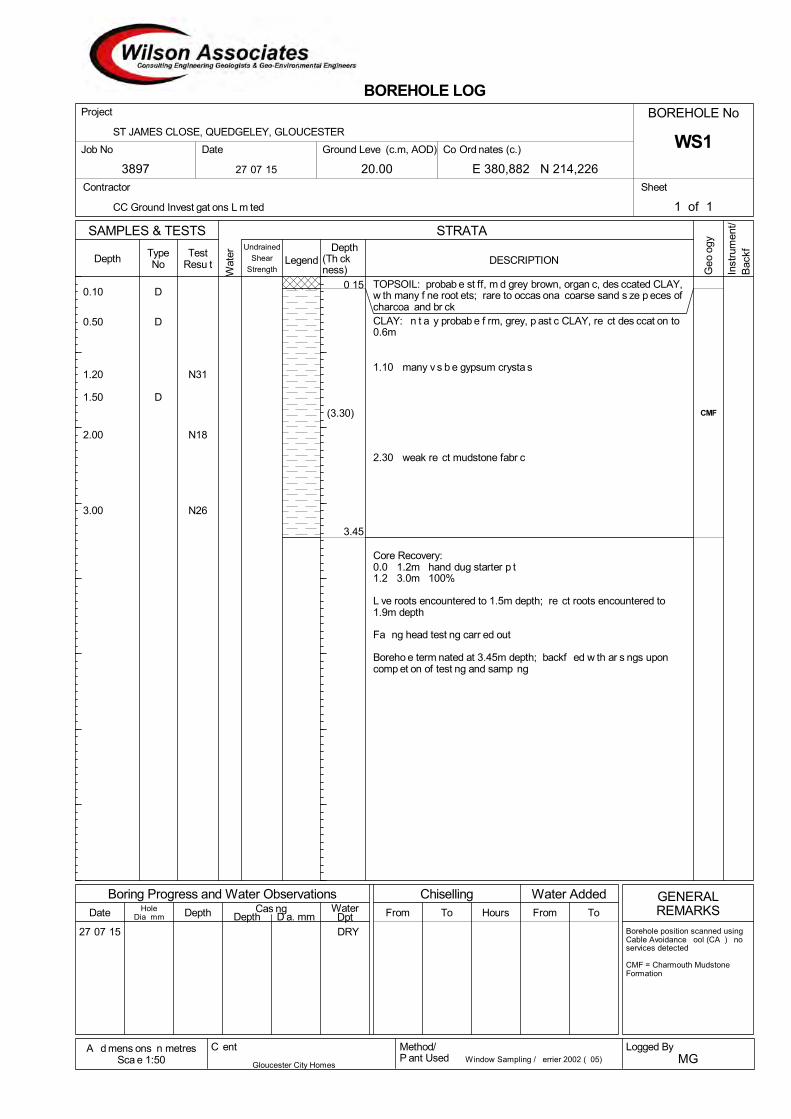
27 07 15
TOPSOIL: probab e st ff, m d grey brown, organ c, des ccated CLAY,w th many f ne root ets; rare to occas ona coarse sand s ze p eces ofcharcoa and br ckCLAY: n t a y probab e f rm, grey, p ast c CLAY, re ct des ccat on to0.6m
1.10 many v s b e gypsum crysta s
2.30 weak re ct mudstone fabr c
Core Recovery:0.0 1.2m hand dug starter p t1.2 3.0m 100%
L ve roots encountered to 1.5m depth; re ct roots encountered to1.9m depth
Fa ng head test ng carr ed out
Boreho e term nated at 3.45m depth; backf ed w th ar s ngs uponcomp et on of test ng and samp ng
0.10 D
0.50 D
1.20 N31
1.50 D
2.00 N18
3.00 N26
0 15
3.45
(3.30) CMF
Depth To To
Chiselling Water Added
DESCRIPTION(Th ckness)W
ater
Depth
1 of 1
Hours From
BOREHOLE No
DRY
HoleDia mm
Depth
BOREHOLE LOG
Boring Progress and Water ObservationsWater
Dpt
STRATA
From
Undrained
Shear
Strength
SAMPLES & TESTS
TypeNo
TestResu t
Date Cas ngD a. mm
Legend
Depth
Sheet
20.00
Date
Project
Contractor
A d mens ons n metresSca e 1:50
Method/P ant Used
C ent
GENERALREMARKS
Logged ByMG
WS1Job No
3897
Borehole position scanned usingCable Avoidance ool (CA ) noservices detected
CMF = Charmouth MudstoneFormation
Window Sampling / errier 2002 ( 05)
Co Ord nates (c.)
E 380,882 N 214,226
ST JAMES CLOSE, QUEDGELEY, GLOUCESTER
Ground Leve (c.m, AOD)
27 07 15
CC Ground Invest gat ons L m ted
Gloucester City Homes
Geo
ogy
Inst
rum
ent/
Bac
kf

FALLING HEAD TEST DATA
Client
Gloucester City Homes
Method/Plant Used
Window Sampling / Terrier 2002 (TO5)
Logged By
MG
Project
ST JAMES CLOSE, QUEDGELEY, GLOUCESTER
Borehole No.
WS1 Job No.
3897
Date
27-07-15
Ground Level (c.m AOD)
20.00
Co-Ordinates (c.)
E 380,882 N 214,226
Hole Dimensions: Diameter = 86mm Depth = 3.45
Elapsed Time (mins)
Depth to Water (m)
0 0.51
56 0.51 326 0.51

BOREHOLE PHOTOGRAPHS
Client Method/Plant Used Logged By Gloucester City Homes Window Sampling / Terrier 2002 (T05) MG
Project ST JAMESʼ CLOSE, QUEDGELEY, GLOUCESTER
Borehole No.
WS1 Job No. 3897
Date 27-07-2015
Hand-dug starter pit arisings
Borehole Core

27 07 15
TOPSOIL: probab e f rm, dark brown, organ c, sandy, fr ab e CLAY,w th med um f ne root etsMADE GROUND: probab e f rm, dark brown, sandy, fr ab e CLAY,w th rare fragments of br ck and charcoa0.40 0.45 2No. concrete cobb esCLAY: f rm to st ff, grey brown, p ast c CLAY, w th re ct des ccat onto 0.8m; v s b e gypsum crysta s throughout
1.30 1.80 occas ona mudstone thore cts
1.90 weak re ct mudstone fabr c v s b e
2.60 becom ng st ff
Core Recovery:0.0 1.2m hand dug starter p t1.2 3.0m 100%
L ve roots encountered to 1.4m depth; re ct roots encounteredthroughout
Boreho e term nated at 3.45m depth; backf ed w th ar s ngs uponcomp et on of test ng and samp ng
0.30 D
0.70 D
1.20 N10
2.00 N13
2.50 D
3.00 N25
0 15
0.48
3.45
55
68
86
80
65
90
105
(2.97) CMF
Depth To To
Chiselling Water Added
DESCRIPTION(Th ckness)W
ater
Depth
1 of 1
Hours From
BOREHOLE No
DRY
HoleDia mm
Depth
BOREHOLE LOG
Boring Progress and Water ObservationsWater
Dpt
STRATA
From
Undrained
Shear
Strength
SAMPLES & TESTS
TypeNo
TestResu t
Date Cas ngD a. mm
Legend
Depth
Sheet
20.00
Date
Project
Contractor
A d mens ons n metresSca e 1:50
Method/P ant Used
C ent
GENERALREMARKS
Logged ByMG
WS2Job No
3897
Borehole position scanned usingCable Avoidance ool (CA ) noservices detected
CMF = Charmouth MudstoneFormation
Window Sampling / errier 2002 ( 05)
Co Ord nates (c.)
E 380,845 N 214,205
ST JAMES CLOSE, QUEDGELEY, GLOUCESTER
Ground Leve (c.m, AOD)
27 07 15
CC Ground Invest gat ons L m ted
Gloucester City Homes
Geo
ogy
Inst
rum
ent/
Bac
kf

BOREHOLE PHOTOGRAPHS
Client Method/Plant Used Logged By Gloucester City Homes Window Sampling / Terrier 2002 (T05) MG
Project ST JAMESʼ CLOSE, QUEDGELEY, GLOUCESTER
Borehole No.
WS2 Job No. 3897
Date 27-07-2015
Borehole Core

27 07 15
TOPSOIL: probab e f rm to st ff, dark brown, des ccated, organ cCLAY, w th many f ne root ets; occas ona br ck and charcoafragmentsMADE GROUND: probab e f rm, dark brown, s ty, p ast c CLAY, w thrare who e br cks, f ne grave of concrete and 1No. meta rebarCLAY: f rm, grey, p ast c CLAY; re ct des ccat on fabr c to 0.8m
2.50 becom ng st ff w th gypsum crysta s v s b e
2.80 weak re ct mudstone fabr c v s b e
Core Recovery:0.0 1.2m hand dug starter p t1.2 3.0m 100%
L ve roots encountered to 0.9m depth; re ct roots encountered to1.7m depth
Boreho e term nated at 3.45m depth; backf ed w th ar s ngs uponcomp et on of test ng and samp ng
0.40 D
0.60 D
0.80 D
1.20 N10
2.00 N11
3.00 N22
0 15
0.55
3.45
60
65
83
81
96
(0.40)
(2.90) CMF
Depth To To
Chiselling Water Added
DESCRIPTION(Th ckness)W
ater
Depth
1 of 1
Hours From
BOREHOLE No
DRY
HoleDia mm
Depth
BOREHOLE LOG
Boring Progress and Water ObservationsWater
Dpt
STRATA
From
Undrained
Shear
Strength
SAMPLES & TESTS
TypeNo
TestResu t
Date Cas ngD a. mm
Legend
Depth
Sheet
20.00
Date
Project
Contractor
A d mens ons n metresSca e 1:50
Method/P ant Used
C ent
GENERALREMARKS
Logged ByMG
WS3Job No
3897
Borehole position scanned usingCable Avoidance ool (CA ) noservices detected
CMF = Charmouth MudstoneFormation
Window Sampling / errier 2002 ( 05)
Co Ord nates (c.)
E 380,844 N 214,231
ST JAMES CLOSE, QUEDGELEY, GLOUCESTER
Ground Leve (c.m, AOD)
27 07 15
CC Ground Invest gat ons L m ted
Gloucester City Homes
Geo
ogy
Inst
rum
ent/
Bac
kf

BOREHOLE PHOTOGRAPHS
Client Method/Plant Used Logged By Gloucester City Homes Window Sampling / Terrier 2002 (T05) MG
Project ST JAMESʼ CLOSE, QUEDGELEY, GLOUCESTER
Borehole No.
WS3 Job No. 3897
Date 27-07-2015
Hand-dug starter pit arisings
Borehole Core

27 07 15
TOPSOIL: probab e st ff, dark brown, organ c, des ccated CLAY, w thrare f ne grave s ze fragments of br ck, and many f ne rootsMADE GROUND: probab e f rm/ oose, m d brown, fr ab e, s ght ygrave y SAND/CLAY
CLAY: f rm, grey, p ast c CLAY
1.50 gypsum crysta s v s b e
2.65 becom ng st ff
Core Recovery:0.0 1.2m hand dug starter p t1.2 3.0m 100%
L ve roots encountered to 0.7m depth; re ct roots encountered to2.2m depth
Fa ng head test ng carr ed out
Boreho e term nated at 3.45m depth; backf ed w th ar s ngs uponcomp et on of test ng and samp ng
0.30 D
0.70 D
1.20 N3
1.40 D
2.00 N2
3.00 N20
0.20
0.80
3.45
52
4961
61839188
(0.60)
(2.65) CMF
Depth To To
Chiselling Water Added
DESCRIPTION(Th ckness)W
ater
Depth
1 of 1
Hours From
BOREHOLE No
DRY
HoleDia mm
Depth
BOREHOLE LOG
Boring Progress and Water ObservationsWater
Dpt
STRATA
From
Undrained
Shear
Strength
SAMPLES & TESTS
TypeNo
TestResu t
Date Cas ngD a. mm
Legend
Depth
Sheet
20.00
Date
Project
Contractor
A d mens ons n metresSca e 1:50
Method/P ant Used
C ent
GENERALREMARKS
Logged ByMG
WS4Job No
3897
Borehole position scanned usingCable Avoidance ool (CA ) noservices detected
CMF = Charmouth MudstoneFormation
Window Sampling / errier 2002 ( 05)
Co Ord nates (c.)
E 380,813 N 214,200
ST JAMES CLOSE, QUEDGELEY, GLOUCESTER
Ground Leve (c.m, AOD)
27 07 15
CC Ground Invest gat ons L m ted
Gloucester City Homes
Geo
ogy
Inst
rum
ent/
Bac
kf

FALLING HEAD TEST DATA
Client
Gloucester City Homes
Method/Plant Used
Window Sampling / Terrier 2002 (TO5)
Logged By
MG
Project
ST JAMES CLOSE, QUEDGELEY, GLOUCESTER
Borehole No.
WS4 Job No.
3897
Date
27-07-15
Ground Level (c.m AOD)
20.00
Co-Ordinates (c.)
E 380,813 N 214,200
Hole Dimensions: Diameter = 86mm Depth = 3.45
Elapsed Time (mins)
Depth to Water (m)
0 0.75
80 0.76 158 0.76

BOREHOLE PHOTOGRAPHS
Client Method/Plant Used Logged By Gloucester City Homes Window Sampling / Terrier 2002 (T05) MG
Project ST JAMESʼ CLOSE, QUEDGELEY, GLOUCESTER
Borehole No.
WS4 Job No. 3897
Date 27-07-2015
Hand-dug starter pit arisings
Borehole Core
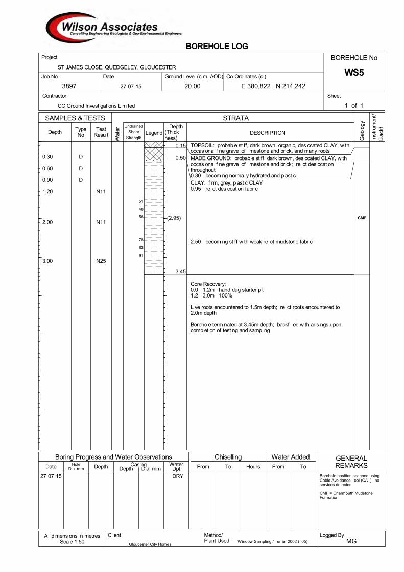
27 07 15
TOPSOIL: probab e st ff, dark brown, organ c, des ccated CLAY, w thoccas ona f ne grave of mestone and br ck, and many rootsMADE GROUND: probab e st ff, dark brown, des ccated CLAY, w thoccas ona f ne grave of mestone and br ck; re ct des ccat onthroughout0.30 becom ng norma y hydrated and p ast cCLAY: f rm, grey, p ast c CLAY0.95 re ct des ccat on fabr c
2.50 becom ng st ff w th weak re ct mudstone fabr c
Core Recovery:0.0 1.2m hand dug starter p t1.2 3.0m 100%
L ve roots encountered to 1.5m depth; re ct roots encountered to2.0m depth
Boreho e term nated at 3.45m depth; backf ed w th ar s ngs uponcomp et on of test ng and samp ng
0.30 D
0.60 D
0.90 D
1.20 N11
2.00 N11
3.00 N25
0 15
0.50
3.45
51
48
56
78
83
91
(2.95) CMF
Depth To To
Chiselling Water Added
DESCRIPTION(Th ckness)W
ater
Depth
1 of 1
Hours From
BOREHOLE No
DRY
HoleDia mm
Depth
BOREHOLE LOG
Boring Progress and Water ObservationsWater
Dpt
STRATA
From
Undrained
Shear
Strength
SAMPLES & TESTS
TypeNo
TestResu t
Date Cas ngD a. mm
Legend
Depth
Sheet
20.00
Date
Project
Contractor
A d mens ons n metresSca e 1:50
Method/P ant Used
C ent
GENERALREMARKS
Logged ByMG
WS5Job No
3897
Borehole position scanned usingCable Avoidance ool (CA ) noservices detected
CMF = Charmouth MudstoneFormation
Window Sampling / errier 2002 ( 05)
Co Ord nates (c.)
E 380,822 N 214,242
ST JAMES CLOSE, QUEDGELEY, GLOUCESTER
Ground Leve (c.m, AOD)
27 07 15
CC Ground Invest gat ons L m ted
Gloucester City Homes
Geo
ogy
Inst
rum
ent/
Bac
kf

BOREHOLE PHOTOGRAPHS
Client Method/Plant Used Logged By Gloucester City Homes Window Sampling / Terrier 2002 (T05) MG
Project ST JAMESʼ CLOSE, QUEDGELEY, GLOUCESTER
Borehole No.
WS5 Job No. 3897
Date 27-07-2015
Hand-dug starter pit arisings
Borehole Core

27 07 15
TOPSOIL: probab e f rm, dark brown, s ty, organ c, p ast c CLAY,w th bands of crushed br ck, and profuse roots from over y ng grassCLAY: f rm, grey, p ast c CLAY
2.50 becom ng st ff
2.80 weak re ct mudstone fabr c v s b e
Core Recovery:0.0 1.2m hand dug starter p t1.2 3.0m 100%
L ve roots encountered to 1.1m depth; re ct roots encountered to2.4m depth
Boreho e term nated at 3.45m depth; backf ed w th ar s ngs uponcomp et on of test ng and samp ng
0.20 D
0.50 D
1.20 N14
2.00 N21
2.80 D
3.00 N29
0.25
3.45
56
61
64
64
95
102
91
(3.20) CMF
Depth To To
Chiselling Water Added
DESCRIPTION(Th ckness)W
ater
Depth
1 of 1
Hours From
BOREHOLE No
DRY
HoleDia mm
Depth
BOREHOLE LOG
Boring Progress and Water ObservationsWater
Dpt
STRATA
From
Undrained
Shear
Strength
SAMPLES & TESTS
TypeNo
TestResu t
Date Cas ngD a. mm
Legend
Depth
Sheet
20.00
Date
Project
Contractor
A d mens ons n metresSca e 1:50
Method/P ant Used
C ent
GENERALREMARKS
Logged ByMG
WS6Job No
3897
Borehole position scanned usingCable Avoidance ool (CA ) noservices detected
CMF = Charmouth MudstoneFormation
Window Sampling / errier 2002 ( 05)
Co Ord nates (c.)
E 380,802 N 214,222
ST JAMES CLOSE, QUEDGELEY, GLOUCESTER
Ground Leve (c.m, AOD)
27 07 15
CC Ground Invest gat ons L m ted
Gloucester City Homes
Geo
ogy
Inst
rum
ent/
Bac
kf

BOREHOLE PHOTOGRAPHS
Client Method/Plant Used Logged By Gloucester City Homes Window Sampling / Terrier 2002 (T05) MG
Project ST JAMESʼ CLOSE, QUEDGELEY, GLOUCESTER
Borehole No.
WS6 Job No. 3897
Date 27-07-2015
Hand-dug starter pit arisings
Borehole Core

27 07 15
TOPSOIL: probab e f rm to st ff, dark brown, s ty, organ c, des ccatedCLAY, w th many f ne root etsMADE GROUND: probab e f rm to st ff, dark brown, s ty, des ccatedCLAY, w th many roots, and f ne grave of br ck and charcoathroughoutCLAY: f rm, st ff, grey, p ast c CLAY; re ct des ccat on fabr c to 0.8m
1.70 weak re ct mudstone fabr c
1.90 becom ng st ff
Core Recovery:0.0 1.2m hand dug starter p t1.2 3.0m 100%
L ve roots encountered to 1.4m depth; re ct roots encountered to1.9m depth
Boreho e term nated at 3.45m depth; backf ed w th ar s ngs uponcomp et on of test ng and samp ng
0.40 D
0.70 D
1.20 D1.20 N13
2.00 N12
3.00 N19
0.20
0.50
3.45
71
69
75
99
98
103
(2.95) CMF
Depth To To
Chiselling Water Added
DESCRIPTION(Th ckness)W
ater
Depth
1 of 1
Hours From
BOREHOLE No
DRY
HoleDia mm
Depth
BOREHOLE LOG
Boring Progress and Water ObservationsWater
Dpt
STRATA
From
Undrained
Shear
Strength
SAMPLES & TESTS
TypeNo
TestResu t
Date Cas ngD a. mm
Legend
Depth
Sheet
20.00
Date
Project
Contractor
A d mens ons n metresSca e 1:50
Method/P ant Used
C ent
GENERALREMARKS
Logged ByMG
WS7Job No
3897
Borehole position scanned usingCable Avoidance ool (CA ) noservices detected
CMF = Charmouth MudstoneFormation
Window Sampling / errier 2002 ( 05)
Co Ord nates (c.)
E 380,789 N 214,251
ST JAMES CLOSE, QUEDGELEY, GLOUCESTER
Ground Leve (c.m, AOD)
27 07 15
CC Ground Invest gat ons L m ted
Gloucester City Homes
Geo
ogy
Inst
rum
ent/
Bac
kf

BOREHOLE PHOTOGRAPHS
Client Method/Plant Used Logged By Gloucester City Homes Window Sampling / Terrier 2002 (T05) MG
Project ST JAMESʼ CLOSE, QUEDGELEY, GLOUCESTER
Borehole No.
WS7 Job No. 3897
Date 27-07-2015
Hand-dug starter pit arisings
Borehole Core


Job No. 3897/2
APPENDIX 4
WASTE CLASSIFICATION CALCULATIONS

Waste Classification Worksheet (October 2013)
Wilson Associates (Consulting) Limited Registered Office: 36 Brunswick Road, Gloucester GL1 1JJCompany No. 6133365
Job No:
Site Name:
Soil/Stratum:
SubstanceAtomic weight
Selected compound Molecular mass Concentration Category of danger Risk Phase H1 H2 H3a (iii) H5 H9 H13 H15
mg/kg % %
expl
osiv
e
oxid
isin
g
flam
mab
le
irrita
nt
irrita
nt
harm
ful
toxi
c
very
toxi
c
carc
enog
enic
cat
egor
y
1 an
d 2
carc
enog
enic
cat
egor
y
3
corro
sive
bur
ns
corro
sive
sev
ere
burn
s
infe
ctio
us
toxi
c re
prod
uctio
n ca
tego
ry
1 an
d 2
toxi
c re
prod
uctio
n ca
tego
ry
3
mut
agen
ic c
ateg
ory
1 an
d 2
mut
agen
ic c
ateg
ory
3
cont
act w
ith w
ater
, air
or
acid
rele
ases
toxi
c ga
ses
cont
act w
ith w
ater
, air
or
acid
rele
ases
ver
y to
xic
gase
s
sens
itizi
ng
dang
erou
s to
ozo
ne
very
toxi
c AN
D m
ay c
ause
lo
ng te
rm e
ffect
s
toxi
c AN
D m
ay c
ause
long
te
rm e
ffect
s
harm
ful a
nd m
ay c
ause
lo
ng te
rm e
ffect
s
ecot
oxic
: no
n-aq
uatic
en
viro
nmen
t
capa
ble
of y
ield
ing
anot
her
subs
tanc
e po
st d
ispo
sl
ARSENIC 74.92 38.00 0.0038 Arsenic trioxide 197.84 0.010034597 Carcinogenic Cat 1 R45 0.01003
T+ R28 0.01003
C R34 0.01003 0.01003
N R50/53 0.01003
CADMIUM 112.41 0 Cadmium chloride 183.32 0 Carcinogenic Cat 2 R45 0.00000
Mutagenic Cat 2 R46 0.00000
Reproduction Cat 2 R60, 61 0.00000
T+ R26 0.00000
T R25, 48/23/25 0.00000
N R50/53 0.00000
CHROMIUM 52 49.00 0.0049 Chromium (III) chromate 452 0.042592308 O R8 0.04259
Carcinogenic Cat 2 R45 0.04259
C R35/43 0.04259
N R50/53 0.04259
CHROMIUM 52 0 Chromium (VI) trioxide 100 0 Carcinogenic Cat 1 R45 0.00000
O R9 0.00000
Mutagenic Cat 2 R46 0.00000
Reproduction Cat 3 R62 0.00000
T+ R26 0.00000
T R24/25, 48, 23 0.00000
N R50-53 0.00000
C R35 R42/43 0.00000 0.00000
LEAD 207.2 290.00 0.029 Lead (II) sulphate 303.26 0.042444691 Reproduction Cat 1 R61 0.04244
Reproduction Cat 3 R62 0.04244
Xn R20/22/33 0.04244
N R50/53 0.04244
MERCURY 200.59 0 Mercury 200.59 0 T R23, 33 0.00000
N R50/53 0.00000
SELENIUM 78.96 0 Selenium 78.96 0 T R23/25 R33 0.00000
N R53 0.00000
BORON 10.81 0 Boron trifluoride 67.82 0 Reacts with water R14
T+ R26/28 0.00000
C R35 0.00000
COPPER 63.55 300.00 0.03 Copper sulphate 159.62 0.075351692 Xn R22 0.07535
Xi R36/38 0.07535
N R50/53 0.07535
NICKEL 58.69 35.00 0.0035 Nickel (II) sulphide 122.7 0.00731726 Carcinogenic Cat 3 R49 0.00732
Xn R43 0.00732 0.00732
N R50/53 0.00732
ZINC 65.38 1300.00 0.13 Zinc oxide 81.41 0.161873662 N R50/53 0.16187
BTEX 78.11 0 Benzene 78.11 0 Carcinogenic Cat 1 R45 0.00000
Mutagenic Cat 2 R46 0.00000
T R48/23/24/25 0.00000
N R51-53 0.00000
F R11 0.00000
Xi R36/38 0.00000
Xn R65 0.00000
BTEX 92.14 0 Toluene 92.14 0 F R11 0.00000
Reproduction Cat 3 R63 0.00000
Xn R48/20, 65
Xi R38 R67 0.00000
BTEX 106.17 0 Ethlybenzene 106.17 0 F R11 0.01003
Xn R20 0.00000
N R51-53 0.00000
BTEX 106.16 0 Xylenes 106.16 0 F R10 0.00000
N R51-53 0.00000
Xn R20/21 0.00000
Xi R38 0.00000
GRO 103.37 0 C5-C10 103.37 0 F+ R12 0.00000
Carcinogenic Cat 2 R45 0.00000
N R51-53 0.00000
Xn R65 0.00000
DRO 183.33 35.00 0.0035 C10-C25 183.33 0.0035 Carcinogenic Cat 3 R40 0.00350
N R51-53 0.00350
Xn R65 0.00350
MINERAL OIL 365 0 C25-C44 365 0 Carcinogenic Cat 2 R45 0.00000
Mutagenic Cat 2 R46 0.00000
N R51-53 0.00000
Reproduction Cat 3 R63 0.00000
Xn R65 0.00000
PAH 252 0.50 0.00005 benzo-a-pyrene 252 0.00005 Carcinogenic Cat 2 R45 0.00005
Mutagenic Cat 2 R46 0.00005
Xi R43 0.00005
Reproduction Cat 2 R60,R61 0.00005
N R50/53 0.00005
PAH 128 0 naphthalene 128 0 Carcinogenic Cat 3 R40 0.00000
Xn R22 0.00000
N R50/53 0.00000
PCB 337.91 0 PCB 337.91 0 N R33-50/53 0.00000
Total (%) 0.04 0.01 0.01 0.08 0.13 0.00 0.01 0.04 0.00 0.01 0.04 0.00 0.04 0.04 0.00 0.00 N/A N/A 0.01 0.00 0.16 0.00 0.00 N/A N/A
Threshold (%) Appendix C1 Appendix C2 Appendix C3 ≥5% ≥20% ≥25% ≥3% ≥0.1% ≥0.1% ≥1% ≥5% ≥1% Appendix C9 ≥0.5% ≥5% ≥0.1% ≥1%Appendix
C12Appendix
C12≥1%* ≥0.1% ≥0.25% ≥2.5% ≥25% N/A N/A
* =
T+ very toxic Xn harmful
T toxic O combustible
N ecotoxic C causes burns
F flammable Xi causes sensitisation
RECORDED CONCENTRATIONS OF ELEMENT GROUPS TESTED AND RESPECTIVE RISK PHRASES (as % of selected compound)
use 1% unless specific conc limits available
H6 H7 H8 H10 H12 H14
LEGEND
*Total Concentration
N.B. The total element concentration used in this analysis equates to the highest recorded concentration obtained from laboratory testing. The respective compound has been selected with reference to Table 3.2 of Part 3 of Annex VI of the CLP Regulation, 2009 (Directive 67/548/EEC).
H11
3897/2
St James Close, Quedgeley, GLOS
COMPOSITE (all soil types)
H4
HAZARD CLASS FOR RESPECTIVE RISK PHRASE