phase-lock techniques for phase and frequency control of...
TRANSCRIPT

Phase-Lock Techniques for Phase and Frequency Control of Semiconductor Lasers
Lee Center Workshop05/22/2009
Amnon YarivCalifornia Institute of Technology
Naresh Satyan, Wei Liang, Arseny VasilyevCaltech
George Rakuljic, Anthony KewitschTelaris Inc.
Support: DARPA Microsystems Technology OfficeCaltech Lee Center for Advanced Networking
Outline
• Semiconductor Laser Optical Phase-Lock Loops
• Coherence Cloning
• Coherent Power Combination
• Broadband Swept-Frequency Sources
• Chirp Multiplication using Four-Wave Mixing

A PLL is a negative feedback control system that forces the LO to track the frequency and phase of the reference signal when in lock
What is a Phase-Lock Loop?
Loop Filter
Local
Oscillator (LO)
Reference Oscillator
LO phase-lockedto reference
Phase error signal
Phase detector
Key elements: Phase detector, voltage controlled oscillator
RF Offset in a heterodyne loop (not shown) can provide additional controlover LO phase and frequency

OPLL basics
A. Yariv, Opt. Lett. 30, pp2191, 2006
RF Offset Signal
Loop Filter
Local Oscillator SCL
Master Oscillator
Output Waveform
Phase detector
Delay
RF Amplifier
~
,M Mω φ
,S Sω φ
,RF RFω φ
S M RF S M RFω ω ω φ φ φ= + = +
PLL Building Blocks
Electronic PLL Optical PLL (OPLL)Phase Detector (Mixer) PhotodetectorVoltage Controlled Oscillator (VCO)
Semiconductor Laser (Current Controlled Oscillator)
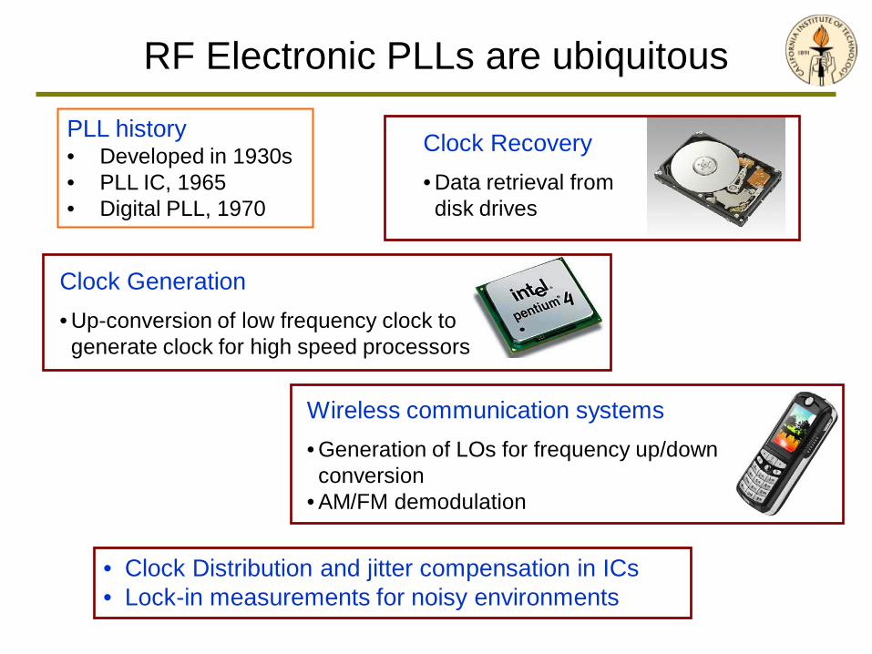
PLL history• Developed in 1930s• PLL IC, 1965• Digital PLL, 1970
RF Electronic PLLs are ubiquitous
Clock Generation• Up-conversion of low frequency clock to generate clock for high speed processors
Clock Recovery• Data retrieval from disk drives
• Clock Distribution and jitter compensation in ICs• Lock-in measurements for noisy environments
Wireless communication systems• Generation of LOs for frequency up/down conversion
• AM/FM demodulation

Phase-Lock OpticsKey applications enabled by phase-lock optics
Optical communication – utilize both phase and intensity of the optical wave• Superior utilization of available bandwidth in high speed networks• Robust modulation formats
Coherence Cloning – Sensor networks
Phase Controlled Apertures• Coherent power combination• Optical phased arrays – rapid beam steering, adaptive optics
Swept Frequency Lasers – electronically controllable chirp• Optical Ranging and LIDAR• 3D imaging and biometrics• Optical Coherence Tomography and biomedical imaging• Arbitrary waveform generation
RF and Terahertz Photonics• Generation and transmission of RF/THz signals on optical carriers• Swept THz sources for imaging / detection / spectroscopy

Phase locking of commercial SCLsHeterodyne OPLL
, S M RF S M RFω ω ω φ φ φ= + = +
Power spectrum of locked beat signal
Slave laser: Commercially available SCLMaster laser: High quality fiber laser
RF RFtω φ+
S Stω φ+
M Mtω φ+

Outline
• Semiconductor Laser Optical Phase-Lock Loops
• Coherence Cloning
• Coherent Power Combination
• Broadband Swept-Frequency Sources
• Chirp Multiplication using Four-Wave Mixing

Coherence cloning with OPLLs
Transfer coherence from high quality expensive fiber laser/solid state laser to a number of inexpensive SCLs using OPLLs
Slave laser frequency noise follows master laser within the loop bandwidth
Signal to noise ratio in coherent interferometric experiments using the phase-locked SCL is determined by the phase noise of the master laser
N. Satyan et al, IEEE J. Quantum Elect. July 2009 (In press)

Coherence of the master laser is cloned within the loop bandwidth.
Coherence Cloning
Power spectral density of laser frequency noise
N. Satyan et al, IEEE J. Quantum Elect. July 2009 (In press)

Outline
• Semiconductor Laser Optical Phase-Lock Loops
• Coherence Cloning
• Coherent Power Combination
• Broadband Swept-Frequency Sources
• Chirp Multiplication using Four-Wave Mixing

Combined Power, two OPLLs
Coherent power combination
94% combining efficiency
VCOs are used to provide RF offset signals to OPLLs
Advantages• Eliminate optical phase or frequency shifters• Fully electronic servo system of low cost and compact size
We have demonstrated power combination of five fiber amplified SCLs with total combined power of 110 W at Telaris Inc.
N. Satyan et al, IEEE J. Sel. Top. Quant. 15, 240-247 (2009)
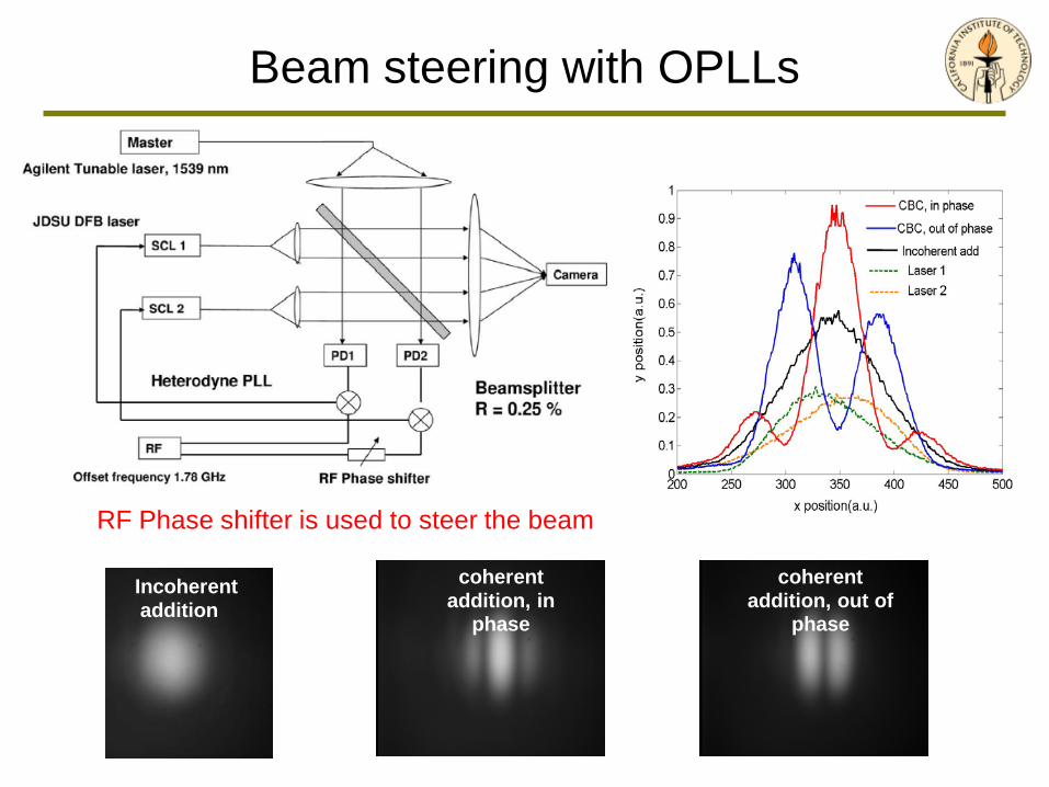
RF Phase shifter is used to steer the beam
Beam steering with OPLLs
Incoherentaddition
coherent addition, out of
phase
coherent addition, in
phase

Outline
• Semiconductor Laser Optical Phase-Lock Loops
• Coherence Cloning
• Coherent Power Combination
• Broadband Swept-Frequency Sources
• Chirp Multiplication using Four-Wave Mixing

Ranging using chirped optical waves
Time
Opt
ical
Fre
quen
cy ω
L
2πB0 tω ξ+ξτ
PDLaunched Reflected
0 tω ξ+ 0 ( )tω ξ τ+ −
( )cosi tξτ∝

RF Reference Oscillator ~
SCL Amplitude Controller
PD
Integrator
Output
Scope /Spectrum
Offset
MZI
Mixer
Rω
( )cos tξτ θ+
0( )L t tω ω ξ= +
τ
DC signal
Rω ξτ=
( )Li t tξ∝
Linear chirp system
Can electronically control the slope of the frequency chirp
Integrator + laser + MZI VCO in a PLL
N. Satyan et al, Optics Express 2009 (submitted)
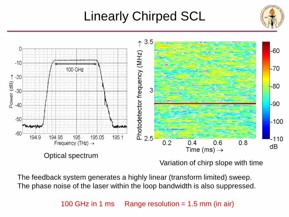
Linearly Chirped SCL
Optical spectrumVariation of chirp slope with time
100 GHz in 1 ms Range resolution = 1.5 mm (in air)
The feedback system generates a highly linear (transform limited) sweep.The phase noise of the laser within the loop bandwidth is also suppressed.

Range resolution measurements
Two targets: Reflections from front and back facet of acrylic plate(a) 5.44 mm (b) 4.29 mm (c) 2.25 mm (d) 1.49 mm
Can resolve down to targets 1.5 mm thick (ref. index = 1.5)
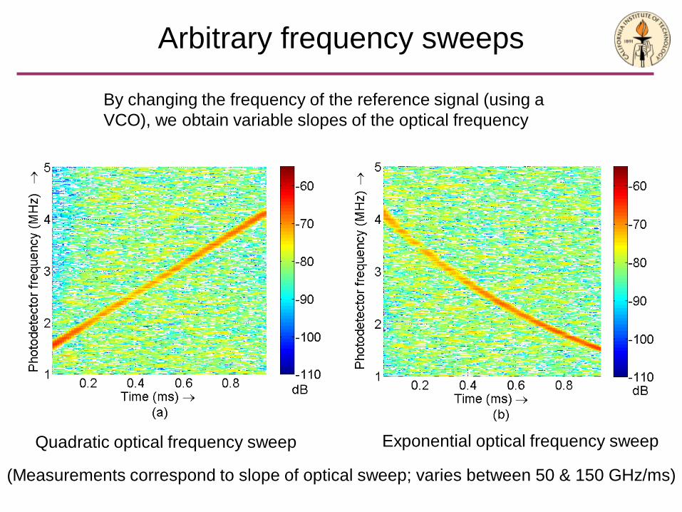
Arbitrary frequency sweeps
Quadratic optical frequency sweep Exponential optical frequency sweep
(Measurements correspond to slope of optical sweep; varies between 50 & 150 GHz/ms)
By changing the frequency of the reference signal (using a VCO), we obtain variable slopes of the optical frequency

Outline
• Semiconductor Laser Optical Phase-Lock Loops
• Coherence Cloning
• Coherent Power Combination
• Broadband Swept-Frequency Sources
• Chirp Multiplication using Four-Wave Mixing

Chirp multiplication by Four Wave Mixing
Fiber amplifier
HNLF
Optical filter
Reference signal ERef(t)
Chirped input Echirp(t)
Frequency swept output
Eout(t)
Optical frequency
2ω0 – ωR
Output
2B
ω0
Input
B
Reference
ωR
Use the four wave mixing process which gives ωout = 2 ωchirp – ωRef (next slide)Optically filter out other FWM outcomes
HNLF: Highly Non-Linear Fiber. Can also use PCF, or silicon waveguides for FWM.
(Other FWM outcome)
2ωR – ω0
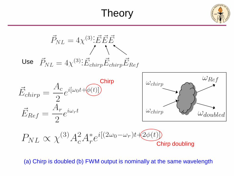
Theory
Use
Chirp
Chirp doubling
(a) Chirp is doubled (b) FWM output is nominally at the same wavelength

22 2 2
02 2 2 2NLPE n E n E
z c t c t tα µ ∂∂ ∂ ∂
= + +∂ ∂ ∂ ∂
( )( )( , ) + c.c2
i t zA zE z t e ω β−∝
( )2
22 *( ) ; 22
out i zNL in R in R out c in RP z A A e D
cω β λβ β β β ω ω
π− ∆∝ ∆ = − − = −
32 * 2(0) (0)2
z j zoutout in R
dA A j A A e edz
α βα γ − − ∆= − −
Theory-II
1. Non linear wave equation
2. Non linear polarization by FWM
3. Define normalized field amplitudes
4. Substitute the sum of input and reference E fields in (2), and look for the termsthat correspond to frequency slope doubling: 2out in Rω ω ω= −
5. Write down the growth equation for the generated field

( )
22 2( ) 2 2
22 2
4 sin1 211
out
LL
Lout in R L
LeeP P P ee
αα
ω α
α
βαγ
α α β
−−
−
−
∆ −
= ⋅ + + ∆ −
Dispersion limited bandwidth
Limited bandwidth due to dispersion
Power generated as a function of output bandwidth
Assuming a dispersion of 0.5 ps/nm.km (pessimistic, but guaranteed in commercial fiber)For 10 THz output BW, maximum fiber length = 1.25 m, Pin = PR = 1.9 W
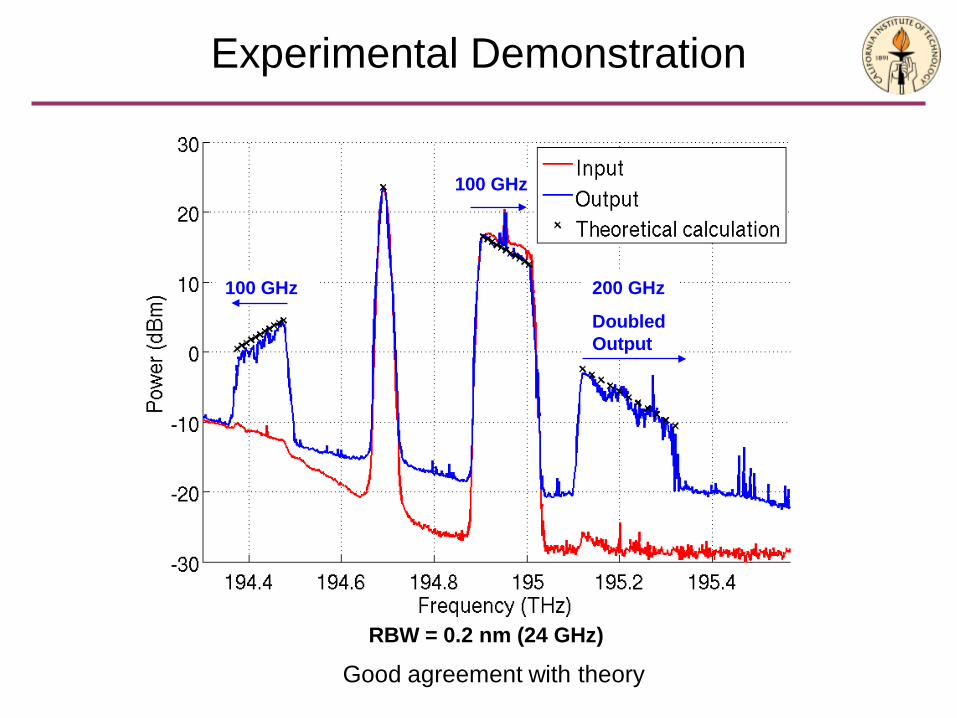
100 GHz
100 GHz
200 GHz
Doubled Output
RBW = 0.2 nm (24 GHz)
Experimental Demonstration
Good agreement with theory

Experimental Demonstration II
Original Sweep Doubled sweep
• Perfectly linear (transform-limited) doubled sweep• Additional noise due to ASE in the amplification stage after filtering
Measurement of slope of optical sweep

Dispersion Compensation
Suppose we periodically invert the sign of the dispersion D, and hence the sign of Δβ
,D L ,D L−
Δβ L = π
Aout(L)
Aout(2L)
Phase matched, Δβ = 0
Aout(L)
Aout(2L)
Aout(2L) = 2 Aout(L) for ALL frequencies can use much lower powers
Aout(L)
Arbitrary Δβ
Aout(2L)
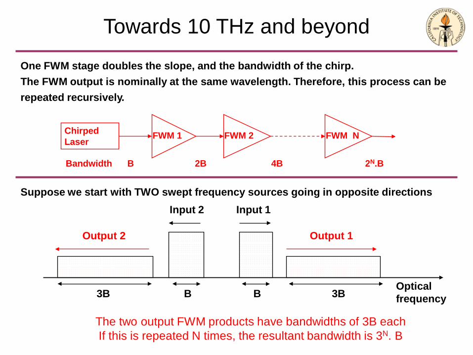
Towards 10 THz and beyond
One FWM stage doubles the slope, and the bandwidth of the chirp.The FWM output is nominally at the same wavelength. Therefore, this process can be repeated recursively.
Chirped Laser FWM 1 FWM 2 FWM N
Bandwidth B 2B 4B 2N.B
Suppose we start with TWO swept frequency sources going in opposite directions
Optical frequency
Output 2
Input 1Input 2
Output 1
BB 3B3B
The two output FWM products have bandwidths of 3B eachIf this is repeated N times, the resultant bandwidth is 3N. B

Universal Terahertz source
Applications of chirped SCLsFr
eque
ncy
Time
Freq
uenc
y
Time0
~1-10 THz
Freq
uenc
y
Time
~1-10 THz
Input CW laser
Swept laser
Need a suitable Terahertz mixer• Photoconductive mixers (Low Temperature Grown GaAs)• Difference Frequency Generation in crystals

Tuning the frequency of a semiconductor laser over THz spans at high speeds
Applications of chirped SCLs
Biological Imaging and OCTSolid state laser source with no moving partsPerfectly linear chirp for real time imaging
Laser ranging and biometricsLong coherence length for imaging at a distanceRapid frequency sweeps
Tunable source for fast spectroscopyBoth Infrared and Terahertz spectroscopyNarrow linewidth of SCL gives better spectral resolution
Terahertz imaging and detection3D (depth resolved) THz imaging using swept THz source
Arbitrary Waveform GenerationFull control over frequency content of waveformPossible to synthesize repetitive waveforms using cascaded OPLLs

Conclusion
Electronically controlled broadband swept-frequency (chirped) semiconductor laser sources and phase-controlled apertures have the potential of becoming new generic components;
Enabling a new spectrum of applications ranging from power combining and steerable optical beams to high resolution 3-D imaging, microscopy and Terahertz optics.

References
• N. Satyan, A. Vasilyev, G. Rakuljic, V. Leyva, and A. Yariv, “Precisely controllable broadband frequency sweeps using a semiconductor laser in an optoelectronic phase-lock loop”, Optics Express (Submitted).
• N. Satyan, W. Liang, A. Kewitsch, G. Rakuljic, and A. Yariv, "Coherent Power Combination of Semiconductor Lasers Using Optical Phase-Lock Loops" (Invited Paper), IEEE J. Selected Topics in Quantum Electronics, vol 15, pp. 240-247, 2009.
• N. Satyan, W. Liang and A. Yariv, "Coherence Cloning Using Semiconductor Laser Optical Phase-Lock Loops", IEEE J. Quantum Electronics, 2009 (In Press).
• N. Satyan, W. Liang, A. Yariv, A. Kewitsch, G. Rakuljic, F. Aflatouni, H. Hashemi, "Coherent power combination of semiconductor lasers using Heterodyne Optical Phase-Lock Loops”, IEEE Photonics Technology Letters, vol. 20, no. 11, pp. 897-899, 2008.
• W. Liang, N. Satyan, F. Aflatouni, A. Yariv, A. Kewitsch, G. Rakuljic, and H. Hashemi, “Coherent beam combining with multi-level optical phase lock loops”, JOSA B, vol. 24, pp. 2930-2939, 2007.
• W. Liang, N. Satyan, A. Yariv, A. Kewitsch, G. Rakuljic, F. Aflatouni, H. Hashemi, and J. Ungar, “Coherent Combining of High Power MOPA Semiconductor Lasers Using Optical Phase-Lock Loops (OPLLs)”, Optics Express, vol. 15, pp. 3201-3205, 2007.
• W. Liang, A. Yariv, A. Kewitsch, and G. Rakuljic, “Coherent combining of the output of two semiconductor lasers using optical phase-lock loops,” Opt. Lett., vol. 32, no. 4, pp. 370–372, 2007.
• A. Yariv, “Dynamic analysis of the semiconductor laser as a current controlled oscillator in the optical phased-lock loop: applications,” Opt. Lett., vol. 30, no. 17, pp. 2191–2193, 2005.