phase sensor . com electric...phase sensor mounting rings breaker ... the matter should be referred...
TRANSCRIPT

PHASE SENSOR MOUNTING
RINGS
BREAKER MOUNTED
INSTRUCTIONS
CONVERSION KITS For Installing the SST Solid State Overcurrent Trip Device on Low Voltage Power Circuit Breaker Types AK-75 and AK-100
PROGRAMMER MOUNTING BRACKETS
COMPARTMENT MOUNTED
PHASE SENSORS (3)
_.,: ','',[.·· �,�, /
,:o ' .
. .
"X" RELAY "W" RELAY \ / v
4TH-WIRE NEUTRAL SENSOR DISCONNECT BLOCKS
MOUNTING BRACKETS
PROGRAMMER UNIT
FLUX SHIFT TRIP DEVICE
Components of SST Conversion Kit for Drawout AK-75 and AK-1 00
GEI-86155
These instructions do not purport to cover all details or variatiOns in equipment nor to prov1de for every p ossible cont1ngency to be met in connection with installation, operation or maintenance. Should further informatiOn be desired or should particular problems anse which are not covered suffJCJently for the purchaser's purposes, the matter should be referred to the General Electric Company.
DISTRIBUTION EQUIPMENT DIVISION PLAINVILLE, CONNECTICUT USA GENERAL . ELECTRIC www .
Elec
tricalP
artM
anua
ls . c
om
www . El
ectric
alPar
tMan
uals
. com

2
CONVERTING AK-75/100 BREAKERS TO THE SST TRIP DEVICE
CONTENTS
I. INTRODUCTION
I. Introduction II. Breaker Disassembly
Ill. Front Frame Conversion IV. Back Frame Conversion V. Breaker Reassembly
VI. Equipment Modifications VII. Testing
These instructions cover installation of the SST solid state overcurrent trip device conversion kits on AK-75 and AK-100 frame breakers originally equipped with EC or Power Sensor type trip devices. Each kit contains the variety of material necessary to convert either type. The kits are designed specifically for use on the breakers listed in Table 1.
Kit installation is straightforward but does require careful workmanship and attention to these instructions. Familiarity with the breaker itself is highly desirable. The general approach is to first strip the breaker of its existing trip devices (either EC or Power Sensor), then install the SST components. Following this, the converted breaker is performance tested prior to restoring it to service.
For the majority of breaker models listed in Table 1, kit installation does not require any customized assembly work. However, some conversions may involve unusual mounting circumstances or accessory combinations which necessitate minor modification/relocation of a component(s). In most instances this supplementary work can be done on site.
Preparatory to beginning the conversion, the installer should verify that the correct kit, current sensors and programmer unit have been furnished - see Tables 2, 3 and 4. Whenever the Ground Fault trip element is furnished for breakers applied on 4-wire systems, note that, in addition to installing the kit on the breaker, an associated neutral sensor (CT) is required for separate mounting in the equipment. Insure also that retrofitted breakers are applied within their short circuit ratings; for example, assuming that as part of a conversion the
PAGE
2 5 5
11 15 20 24
breaker's trip elements are to be changed from Ll to LS, then the short time rating would govern the application.
For identification purposes, all kit materials are itemized on tile parts lists included with each kit. The item numbers on those parts lists correspond to the part numbers used on the illustrations herein. Any original breaker parts that are to be reused bear the designation RE.
As a service related consideration, the installation of SST kits provides an excellent opportunity to perform normal maintenance on the breaker proper, particularly while the front and back frames are separated. Such procedures are covered in Maintenance Manual GEK-7303; renewal parts are available as listed in Bulletin GEF-4395 (AK-75) and GEF-4396 (AK-100). Copies of these publications are included in each kit.
TOOLS REQUIRED
Socket Set Open End Wrenches Screwdrivers Allen Wrenches Tru-arc Pliers
NOTE
Pliers Electric Drill 6" Scale Crimping Tool
Although designed specifically for the breaker models in Table 1, these kits in many instances can be employed for conversion of the earlier AK-1-75/100 types. Undertaking such conversions should be a local decision and may involve additional modification depending upon the breaker's vintage and its accessory complement.
www . El
ectric
alPar
tMan
uals
. com
www . El
ectric
alPar
tMan
uals
. com

Table 1 - Convertible Breaker Models
A-C Breaker Type Trip Device Frame Drawout
Size Stationary EC Power (Amp) AKD AKD-5 Sensor
3000 NA AK-2-75 AK-2A-75 X NA AK-3-75 AK-3A-75 X
4000 NA AK-2-100 AK-2A-100 X NA AK-3-100 AK-3A-100 X
NA =No Kit Available
Table 2- Basic Conversion Kits for Breakers in Table 1
Table 3- Tapped Current Sensors
Basic Kit Cat. 343L697 - (Gp. No.)
Drawout With 4th-Wire W /0 4th-Wire Breaker Neutral Sensor Neutral Sensor
Type
Drawout Breaker
Type
Man. or Elec. Man. or Elec. AK-75 AK-75 G2 G1
AK-100 G4 G3 AK-100
TABLE 4 - Programmer Units
Trip Breaker Programmer Elements Frame Cat. No. (i)
None
UNITS WITHOUT GROUND FAULT
LS -
LST -
AK-75 Ll 14 AK-100 343L696G LIT 17
LSI -
LSIT -
UNITS WITH GROUND FAULT
LSG -
LSGT -
LIG 8 AK-75 LIGT 11
LSIG -
LSIGT -343L697G
LSG -
LSGT -
LIG 14 AK-100 LIGT 17
LSIG -
LSIGT -
Cat. No. Sensor Ampere Phase 4th-Wire
Range Sensors Neutral Sensor
1200-343L697G37 343L671G61 3000
1600-343L697G38 343L671G62 4000
Group No.
Short-time Pickup
1.75L-4L
37 39
--
38 40
19 21
--
20 22
23 25
--
24 26
3L-1 OL
13 16
--
15 18
7 10
--
9 12
13 16
--
15 18
CD Trip Element Abbreviations
L = Long Time S = Short Time I = Instantaneous G = Ground Fault
3 www . El
ectric
alPar
tMan
uals
. com
www . El
ectric
alPar
tMan
uals
. com

4
Fig. 1 - SST programmer unit mounted on AK-100 breaker.
if;_ Of Crank Bearing
V4-20 Tap 3-Holes
2.94
�a�� I I
B ear0j_ _ _j _ ---+--/
I I I I I I I I I I I
-'
4.625
-(�)-H---L-
Left side view of center channel
Fig. 2 - Drilling plan for programmer mounting bracket.
www . El
ectric
alPar
tMan
uals
. com
www . El
ectric
alPar
tMan
uals
. com

II. BREAKER DISASSEMBLY
WARNING: Before starting any work, disconnect the breaker from all power sources (primary and secondary) and place in a clean work area.
1 . Be sure the breaker is open.
2. Remove the arc quencher retaining bar.
3. Remove the arc quenchers, lifting them clear of the movable arcing contacts. Remove the two inter-phase barriers.
4. Separate the breaker front frame from its back frame. Refer to GEK-7303, Page 7. For Power Sensor-equipped breakers, see pp. 35-39 for additional information.
5. Remove the overcurrent trip devices, referring to Maintenance Manual GEK-7303 as follows:
• EC-1 B type, pp. 26-29.
• Power Sensor type, pp. 35-39.
Ill. FRONT FRAME CONVERSION
1 . Referring to Figs. 1 , 4 & 5, install the programmer mounting brackets 70 and 75 on the breaker's center channel.
Note 1 On some breakers the holes for mounting screws 71 and 73 already exist; if they do not, then layout, drill and tap the three holes per Fig. 2.
Note 2 On electrically operated AK-2/2A-breakers of the quick-close variety, it may be necessary to relocate the anti-pump relay "W" to make space for the SST programmer unit. On these breakers the "W" relay normally mounts on the left side of the center channel, sharing a common mounting bracket with control re�ay "X". Remove the "W" relay and relocate it to the upper left of the front frame as shown in the BEFORE and AFTER views of Fig. 3. In the process, remove the "X" relay, discard its original mounting bracket and then remount it in the same location using new bracket 207.
2. The next step is to mount the flux shift trip device, proceeding as follows: a. Layout and drill three (3) .209 DIA. mounting
holes in the left side of the front frame as shown in Fig. 6.
b. Mount the flux shift trip device assembly 40 to the side of the front frame per Figs. 5 and 6, being sure to position insulating sheet 41 and the connector support plate 50 next to the mounting base as indicated.
Note If the breaker is an AKU-50 fused type, take care to position the flux shift trip device sufficiently upward to avoid interference with the coil of the open fuse lockout (OFLO) device.
c. Identify the programmer wire harness (part 1 41 or 1 43) and mount its male connector (P2 on Fig. 6) to support plate 50 using screws 51 .
d. Insert the two sleeve-terminated ends of harness X (the leads from the flux shift trip device) into female connector P1 on the opposite end of the programmer harness -red wire into socket B, black wire into socket E. See Table 5 and the applicable harness connection diagram- Fig. 1 6 or 1 9.
Note Each kit contains a special Amp tool for removing leads from the connector sockets, should the need arise.
e. Mount trip paddle 45 onto the br�aker trip shaft per Fig. 6. Adjust the length of the trip rod on the flux shift trip device per Fig. 9. A front frame with flux shift trip device mounting completed is shown in Fig. 1 0.
3. Form harness X along with the programmer harness and wire tie them to the front frame per Fig. 5.
5 www . El
ectric
alPar
tMan
uals
. com
www . El
ectric
alPar
tMan
uals
. com

6
'--
/ /
I I -
I '
\ ,GJ., -,.._
X .__ I I -----
�---
cc
. I .
BEFORE
FRONT VIEWS OF BREAKER
..- ,
� - - � I l@l) \
...... _,
a� cc
=
X H. w I I I I I . ---- I • . I .
� AFTER
Fig. 3 - Remounting of "W" and "X" relays - required only on quickclose, electrically operated breakers equipped with EC trip devices.
Use loctite on these screws
71
70
Control Wiring
RE
NOTE: Installation of this new mounting bracket for the "X" relay is required only on quick-close, electrically operated breakers equipped with EC trip devices.
�
Center Channel
With the front and back frames separated, remove the "W" and "X" relays and their mounting brackets; install new mounting bracket 207 and remount the "X" relay. Relocate and remount the "W" relay per figs. 5 and 6 . SIDE VIEW FRONT VIEW
Fig. 4 - Installing SST programmer mounting bracket on center channel of front frame; remounting the "X" relay.
www . El
ectric
alPar
tMan
uals
. com
www . El
ectric
alPar
tMan
uals
. com

Connector
Tab "C"
BOTTOM VIEW OF PROGRAMMER
10 0 0 0 OSJ c=J
[am§l£J 1ooooo1§11 0
FRONT VIEW OF PROGRAMMER
New location for "W" relaysee fig. 6 also.
203, 204,
Mount programmer 175 into bracket "E" by inserting tab "C" into slot "D", then tighten screws "A".
205, 206 ---� ll-....L......,._.,-----..,
202, 203, ---"ill!l 204, 206
200
Bracket --+f-+---.., "E"
Slot "D"
52
Mounting 44
base of 43 Flux Shift 41 Trip Device 42
40
Tie leads from flux shift trip device to programmer harness
50
"W" Relay
Rubber Grommet and Flat Washers
�i", r/.J..._;.l_11
r � L, I I
�===� I P1 I L-, r-
""',_,J 1�\'/i--1
0
FRONT VIEW
Fig. 5 - Converted front frame
See fig. 4 . J 7 www .
Elec
tricalP
artM
anua
ls . c
om
www . El
ectric
alPar
tMan
uals
. com

8
Note: Crossbar side link is part of back frame assembly
Locate paddle on breaker trip shaft so that it horizontally centers on the trip rod
See fig. 9 on how to adjust trip rod
P 2 Connector -+-+------r-
Drill (3) .209 dia. holes
Relocated "W" Relay (when necessary)
7.56 R_e_f. ___ ---"�
r.0-.., fA' I [_ ___ _JV I
200
201
Drill (2) .257 dia. holes in link, tap for �6 x 18
Existing Holes
I Harness X
to Programmer
4�
�---/�'---------� Assemble P41 between P40 and CB Frame
Fig. 6 - Side view of front frame showing mounting of flux shift trip device.
www . El
ectric
alPar
tMan
uals
. com
www . El
ectric
alPar
tMan
uals
. com

Left side link on left pole
4
Actuator Bracket Buffer Stud
Fig. 7 - Flux shift trip device -reset linkage attachment.
1 . Actuator 2. Actuator arm 3. Trip rod 4. Trip rod adjuster end 5. Reset linkage 6. Actuator bracket 7. Mounting base
Fig. 8 - Flux shift trip device assembly with operating linkages.
9
www . El
ectric
alPar
tMan
uals
. com
www . El
ectric
alPar
tMan
uals
. com

10
SIDE VIEW
Trip paddle in "Mechanism Reset" position
Side link
ADJUSTMENTS: � 1 . Trip rod length: Adjust gap to 0.093" -+- 0.015"
using 0.093" diam. rod as shown.
2. Actuator bracket: As the crossbar travels be-tween the "breaker closed" and "breaker open" positions, the tang of the actuator bracket must clear the buffer stud. If insufficient clearance exists, loosen it's two mounting screws and rotate the bracket clockwise to take up mount-ing hole slack. Retighten screws.
.093"Dia. rod
Adjuster end
Trip rod in "Reset" position
Crossbar (Bkr. open)
Fig. 9 - Flux shift trip device adjustments.
Fig. 10 - Rear view of an AK-50 front frame showing mounting of the flux shift trip device. The arrangement on AK-75/1 00 units is identical. www . El
ectric
alPar
tMan
uals
. com
www . El
ectric
alPar
tMan
uals
. com

IV. BACK FRAME CONVERSION
1. Identify the crossbar side link on the left side of the breaker's left pole; layout, drill and tap the two .257 DIA. holes in it as shown in Fig. 6. These holes are used later to attach the trip device actuator bracket (Step V2).
2. Mount the three phase sensors (100) on the upper primary studs of the breaker as indicated in Figs. 11, 12 and 13. Position each sensor so that its leads will exit between the pole bases per Fig. 13, then tighten the rings.
3. Mount the three sensor terminal boards (TB1, TB2 and TB3) to the rear of the back frame as shown in Fig. 13, using hardware provided.
4. Form each sensor's leads downward between
the pole bases and thru the hole in its terminal board per Fig. 13, then wire tie and solder to the terminals as indicated. Be sure to position wire colors as shown.
5. On breakers being equipped with 4-wire ground fault, mount neutral sensor disconnect block 225 below the left pole on the rear surface of the back frame per Fig. 13; be sure to select the proper mounting bracket as instructed in Fig. 15.
6. Attach wire harness (part 140, 142, 150 or 151) to the back frame per view B of Fig. 16 or 19, whichever applies. On TB1, TB2 and TB3, position each tap lead (black) on the same selected amp rating. Form and tie per Fig. 14.
Fig. 11- SST current sensor mounting.
11 www . El
ectric
alPar
tMan
uals
. com
www . El
ectric
alPar
tMan
uals
. com

5
12
ALLOW SPACE FOR
PRIMARY l FINGERS
r-----------------------�
To mount sensor 100, engage �________,
its anti-turn lugs with notch in ring 113, then position on stud so that sensor leads exit as shown in Fig. 13.
1. SST phase sensor
STUD
2. EC-1 B trip device (before removal) 3. SST sensor tap terminal boards 4. Primary stud type typical of Power Sensor equipped breakers 5. Primary stud type typical of EC equipped breakers
Fig. 12 - Composite Rear View - SST Conversion of AK-100. The AK-75 conversion is similar.
2
100
-- 113
SIDE VIEW
www . El
ectric
alPar
tMan
uals
. com
www . El
ectric
alPar
tMan
uals
. com

109 110 112 119
RIGHT POLE
I
'114
MAKE ONE COMPLETE WRAP AND SOLDER IN PLACE (5 TERMINALS)
CENTER POLE
ROUTE LEADS BETWEEN POLE BASES
II I! I[ II II I
----
100
II 11
LEFT 11 POLE II
I I
108 --------++-- 1 09
225
When used, the 4th-wire neutral sensor disconnect block 225 mounts on top of tap terminal board 108 via its two lower mounting screws. The AKD-5 type mounting is illustrated. The arrangement for AKD types is identical except for use of a different mounting bracket - see Fig. 15.
110 111
Fig. 13- Typical AK-75/100 backframe conversion- rear view.
13 www . El
ectric
alPar
tMan
uals
. com
www . El
ectric
alPar
tMan
uals
. com

14
140 or 142 (AK-75)
150 or 151 (AK-100)
After rejoining front and back frames, engage connector P3 with mating connector P2 on front frame.
LEFT POLE (0A)
CENTER POLE (0 B)
When 4th-wire neutral disconnect is used, route leads to rear of breaker thru hole as shown.
I I I
01 1---'='-----1- _j
RIGHT POLE (0C)
i I II
I ···�·
-l 01
I I I I I
ol _ _J
Fig. 14 - Front view of converted AK-75/100 back frame showing sensor terminal boards and harness arrangement.
AKD-5 Type
As received in kit, block is assembled to the AKD-5 type bracket.
AKD Type
---239
For AKD installation, remove block from AKD-5 bracket and remount it on bracket 239.
Fig. 15 - Selection of mounting brackets for attaching the 4th-wire neutral sensor disconnect block to AK-75 & 100 drawout breakers.
I I i
www . El
ectric
alPar
tMan
uals
. com
www . El
ectric
alPar
tMan
uals
. com
'
V. BREAKER REASSEMBLY
1. Rejoin the front and back frames. Refer to GEK-7303 page 7 as necessary. Join harness connectors P2 & P3.
2. Referring to Figs. 6 and 7, attach the flux shift trip device actuator bracket to the left pole crossbar side link (previously drilled in Section IV). Be sure it clears the buffer stud as described in Fig. 9.
3. Install the programmer unit 175 into its mounting bracket on the breaker front frame as shown in Fig. 5. Join female connector P1 of the breaker harness to the male connector on the rear of the programmer.
CAUTION - To avoid shock hazard and possible damage to wire harness and sensor coils, insure that all harness connectors (P1, P2 and P3) are securely engaged before any attempt is made to energize the breaker.
Conversion of the breaker is now complete. Manually close and trip the breaker several times to insure proper mechanical operation. Use the maintenance handle to do this on electrically operated breakers. Recheck the flux shift trip device linkage and adjustments per Fig. 9.
Proceed next to Section VI -EQUIPMENT MODI FICATIONS. If these are not required, go directly to Section VII- TESTING.
15 www . El
ectric
alPar
tMan
uals
. com
www . El
ectric
alPar
tMan
uals
. com

16
FRONT VIEWS
P3
WHITE
PROGRAMMER HARNESS 141
I
FLUX SHIFT TRIP ACTUATOR
BACK FRAME _HARNESS
140 For AK- 75 150 For AK-1 00
TB1 LEFT POLE
WHITE
BLACK
TO PROGRAMMER
+ P1
HARNESS X
TB2 CENTER POLE
0 FRONT FRAME
t +
BACK FRAME
®
WHITE
BLACK
TB3 RIGHT POLE
Fig. 16 - Harness connections for drawout and stationary breakers used on 3-wire systems - with and without ground fault. For elementary diagrams see Figs. 1 7 and 18.
��1,
www . El
ectric
alPar
tMan
uals
. com
www . El
ectric
alPar
tMan
uals
. com

LEFT POLE CURRENT SENSOR
I � I
IA
I BREAKER I
BACK FRAME 1 �I I
I
P 3 I
I I
/ ' ' / ' / ' / ' ....
I I
I )===)===}---1-
P2
:r '--'-
..___ I I +-I I
P1 - - - -
,J WHITE ./L ' BLACK ./L '' WHITE ./L ' BLACK
WHITE / ' BLACK / '
RED L ! BLACK
'----
-
r--
A
c
D
F
H
K
B
E '--
,-----, I
(48V de)
(TO SCR ANODE)
I
I I I I
:_J-J--1--J r rr
FLUX SHIFT TRIP DEVICE
I I I I I ___
__ _, I --;---_j
LOAD I BREAKER
FRONT FRAME PROGRAMMER
UNIT
Fig. 17 - Elementary diagram - drawout breaker without ground fault.
LEFT POLE CURRENT SENSOR
I t lA I
I BREAKER I
BACK FRAME 1 �
P 3 I
I I I I I I I )===)===}---1- +-
P1
WHITE
BLACK
WHITE
BLACK
WHITE
BLACK
.-:-=-+-o-+-< �+0+--- ( 48V. de)
J.=��<>+-< f-+-0-+--. (TO SCR ANODE)
I I I I I _ y-_ f
__ Y / ___ : 11
1 t � � FLUX SHIFT I I I _____ _, I
r r r L_ :IP�E�VICE
-
LOAD BREAKER
FRONT FRAME
- -;---_j
PROGRAMMER UNIT
Fig. 18 - Elementary diagram- drawout breaker with 3-wire ground fault.
17
www . El
ectric
alPar
tMan
uals
. com
www . El
ectric
alPar
tMan
uals
. com

FRONT VIEWS
Both leads have ring terminals.
� .... ------1' .. -- - --'
BLACK .��' WHITE \\ .. .... ......... .. "'\\ j"J( -.--r"J.CI
1 \:)1 1 1 �1 1 TAP I ICOMI I I I I I I I I I I I __ .J __ • __ J
Secondary disconnect block for 4th-wire neutral sensor-mounts on rear of back frame.
P3
PROGRAMMER HARNESS 1 43
/
t
TO PROGRAMMER
+ P1
HARNESS X
FLUX SHIFT TRIP ACTUATOR
BACK FRAME HARNESS , ___ 1 42 For AK-75
1 51 For AK-100
TB1 LEFT POLE
TB2 CENTER POLE
0 FRONT FRAME
+ t
BACK FRAME
®
TB3 RIGHT POLE
Fig. 19 - Harness connections for drawout breakers equipped with 4- wire ground fault. For elementary diagram see Fig. 20.
1 8 www . El
ectric
alPar
tMan
uals
. com
www . El
ectric
alPar
tMan
uals
. com

�A �B �C
BREAKER I I I BACK FRAME A A A
--------... r -LEFT POLE CURRENT SENSOR
I • I
IA
I
P3 P2 P1 -I-------,
,------WHITE
BLACK
WHITE
BLACK
WHITE
NEUTRAL I SENSOR 1
DISCONNECT I ----1 BLACK
I I
EQUIPMENT /� MOUNTED I NEUTRAL � SENSOR 1
IN
I
WHITE
BLACK
I I I � (48V dc)
I l>==y=)==f)---�-l-� Z�osD�� I
I_ -i-��- _j : i���XD������ �--�-----� r r r ---�---------�
4-WIRE LOAD
BREAKER PROGRAMMER FRONT FRAME UNIT
Fig. 20 - Elementary diagram- drawout breaker with 4-wire ground fault.
Table 5 - SST Harness Wire Table
TO PROGRAMMER FROM
Harness Connector Wire TO
Socket Color Number 1
MALE
� A White
TB1 (</>A) c Black
D White TB2 (</>B) F Black
H White TB3 (cf>C) K Black
8 Red Flux Shift E Black Trip Device
L White 4th-wire Neutral
Disconnect Block N Black when used HARNESS CONNECTOR
19
www . El
ectric
alPar
tMan
uals
. com
www . El
ectric
alPar
tMan
uals
. com

VI. EQUIPMENT MODIFICATIONS
The following modifications are required ONLY in conjunction with breakers being equipped with 4-wire Ground Fault trip elements.
1. Mount the neutral sensor in the outgoing neutral lead, normally in the equipment's bus or cable compartment. Be sure to observe the sensor's LINE & LOAD directional markings. See Fig. 21 for the sensor's bar drilling plan. Check to insure that the neutral and phase sensors match, i.e., have the same ampere range.
--------- 10.75 -1-.032
2. Mount the 4th-wire neutral sensor stationary disconnect block 226 inside the breaker compartment at the lower rear as shown in Figs. 23 & 24, whichever applies. Be careful to select the correct mounting bracket (part 227, 228 or 229).
3. Connect the neutral sensor to disconnect block 226 per Fig. 25 wiring instructions.
75lr---+
�-
-
1
_
.7
_
5-
--�-----f,:@ U ___ © ,.!-: -
+-
�--
-
1
-
.75
-
,_
t----,---r �-r 1/1 $--$ ! EI�.OM : -$-�$- l I � . 1 [;14000 I I 1 ::9. O
�
6_ & : JJ:)1600 : . : : - ; � ���� - i ?I ··' - �' I T J ---+-i-----+Hf+---1-
\.V "V I �� I t___._�:@ - - -----�: �---ll'---1-:..t.::t-'/ _j -z625 HOLES
3.84
12.25 cL >-1-0 � ��,--------�__1
-- -i __ I
I I I
I
; I
I ---�- - I
I I
,) I I "1;..*-�------- �==!ltft·HoiE LOA.qjj==�--------�. I 1- -1 I
I
I l I l
�---------'11--_ �-� - - -- � �----- �-,!!: ______ ...., ___l
Sensor Cat. No.
3.92
343L671G61 343L671G62
Fig. 21- Outline of SST 4th-wire neutral sensors (from Outline Dwg. 5688227).
20
Amperes
1200-3000 1600-4000
3.42
www . El
ectric
alPar
tMan
uals
. com
www . El
ectric
alPar
tMan
uals
. com
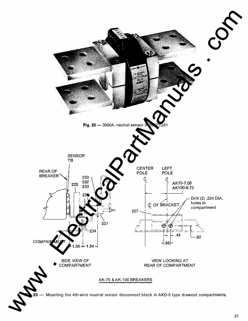
Fig. 22- 3000A. neutral sensor 343L671 G61
REAR OF
SENSOR TB
BREAKER� I
SIDE VIEW OF COMPARTMENT
CENTER LEFT POLE POLE
l d ��;�o�s���rill (2) .224 DIA .. I ¢ OF BRACKET holes in 't. compartment
227 I ---..__r====I=-:::::F-i-=1
VIEW LOOKING AT REAR OF COMPARTMENT
AK-75 & AK-100 BREAKERS
Fig. 23 - Mounting the 4th-wire neutral sensor disconnect block in AKD-5 type drawout compartments.
21
www . El
ectric
alPar
tMan
uals
. com
www . El
ectric
alPar
tMan
uals
. com

22
REAR OF ! BREAKER\!
I I
SENSOR TB
REAR OF COMPARTMENT
CENTER POLE
<t LEFT POLE
<t
.44
239 BRACKET 1----------1 2.62 ------1
Side View of Compartment
I I
REAR OF I
BREAKERi
SENSOR TB
23(1 BRACKET ._, ------12.62
Side View of Compartment
AK-75 BREAKERS
REAR OF COMPARTMENT
238
View Looking at Rear of Compartment
CENTER LEFT POLE POLE
c f---9.75 Drill (2) .281 DIA. holes in compartment
1 -12 .50 s;:,::::tl
AK-100 BREAKERS
-.44
View Looking at Rear of Compartment
Fig. 24 - Mounting the 4th-wire neutral sensor disconnect block in AKD type drawout compartments.
www . El
ectric
alPar
tMan
uals
. com
www . El
ectric
alPar
tMan
uals
. com

INSTALLATION NOTES
• Observe LINE and LOAD markings when making bus or cable connections.
• Bond sensor on LINE side only.
• Maintain polarity of sensor secondary leads when connecting to breaker, i.e., TAP to TAP, COM to COM.
Run secondary leads together and tie to prevent loops. Use #14 wire size minimum.
Stationary disconnect block in drawout breaker compartment .
Tap Com
Neutral ...---- Sensor t-------1
__, .28r-
#5 Binding head screw
#6 Pan head screw
Front view looking into breaker compartment. --$--�
Tap Common
4th-Wire neutral sensor stationary disconnect block .
Spring loaded butt contacts.
Fig. 25 - Connecting the 4th-wire neutral sensor.
23 www . El
ectric
alPar
tMan
uals
. com
www . El
ectric
alPar
tMan
uals
. com

24
VII. TESTING
Before reinstalling the breaker to service, perform steps 1, 2 & 3 below:
1. Megger breaker primary circuit using a 1 OOOV megger.
2. Verify that all tap leads have been properly connected to the terminal boards by checking the tap-to-tap resistances of each current sensor against the values in Table 6. These data apply both to phase and neutral sensors.
Table 6- Sensor Resistance Values
Tap Tap Breaker Terminal Lead
(AMP) Color
1200 Black 1600 Yellow
AK-75 2000 Red 3000 Green
1600 Black 2000 Yellow
AK-100 3000 Red 4000 Green
Resistance in ohms between COMMON
terminal (white lead) and TAP
terminal
13.4-15.7 18.3-21.5 23.5-27.6 37.7-44.3
18.1-21.2 23.1-27.2 37.0-43.4 52.4-61.5
MALE END
3. Perform either of the following tests:
A - When available, portable test sets TAK-TS1 or TAK-TS2 should be used to check the breaker and its trip device for proper operation. Instruction manuals GEK-64454 and GEK-73300-1 respectively apply.
B
FEMALE END
Using a single-phase, high current-low voltage test set, test each trip element (L, S, I, G) to assure proper protective device operation. Compare results with applicable timecurrent characteristic curves reproduced on pages pages 26 & 27.
NOTE:
When high-current testing units equipped with a ground fault trip element, the latter must be deactivated by using Ground Fault Defeat Cable Catalog #TGFD as shown in Fig. 26 below. If this defeat cable is not available, the breaker can be tested by connecting two poles in series such that the currents are in opposing directions.
Any SST Programmer Unit with Ground Fault Element
Fig. 26 - Cabling diagram with Ground Fault Defeat Cable. inserted be-tween breaker harness and SST Programmer Un1t - for use during single-phase, high current-low voltage testing.
www . El
ectric
alPar
tMan
uals
. com
www . El
ectric
alPar
tMan
uals
. com

TABLE 7 -TRIP CHARACTERISTICS -SST CONVERSION KITS
Applicable time-current Curves: GE5-6033B, 6034A, 6035B
Frame Breaker Sensor Taps Frame Size (X) (Am-Type
peres) (Amperes)
AK-15 225 70,100,150,225 70,100,150,225
AK-25 600 or 200,300,400,600 300,400,600,800
AK-50 1600 or 600,800,1200,1600
AKT-50 2000 800,1200,1600,2000
AK-75 3000 1200,1600,2000,3000
AK-100 4000 1600,2000,3000,4000 NOTES <D
<D x = Sensor ampere tap = trip rating ® Pickup tolerance = ± 10%
SST Programmer Adjustment Range (Set Points)
Ground Fault Long Time Short Time
Pickup
(Multiple) of X
.5, .6, .8, 1, 1.5, 2 (X)
.25, .3, .4, .5, .6, .7 (X) .2, .25, .3,
.4, .5, .6 (X) .2, .22, .25,
.3, ;35, .37 (X) .18, .2, .22,
.25, .27, .3 (X) <ID
Pickup Delay DelaJ Pickup Band
(L) Ban (Multiple) (Multiple)
(Seconds) of X (Seconds) ofL
Maximum Maximum 1.75, 2, 0.30 22 2.25, 2.5,
3, 4 (L) lntermed. .6, .7, .8, lntermed.
0.165 .9, 1, 1.1 10 or (X)
Minimum Minimum 3,4, 5, 6, 0.065 4 8, 10 (L)
@) (g) <ID <ID @Time delay at lower limit of band@ 6L @ Time delay at lower limit of band
DelaJ Ban
(Seconds)
Maximum 0.35
lntermed. 0.21
Minimum 0.095
@)
lnstan· taneous Pickup (Multiple)
ofL
4, 5, 6, 8, 10, 12 (L)
<ID
25 www . El
ectric
alPar
tMan
uals
. com
www . El
ectric
alPar
tMan
uals
. com

26
� MULTIPLES OF LONG-TIME PICKUP (L) .5 .I .7 .1. I 2 ' 4 • I 7 I 111 .. .. .. SO to 7Dtoto! ! II I ! I !!I !!I I ! i ! un�
"'
1100 ... 100 700 ... "' ...
...
, ..
100 .. 10 " .. .. " � 40
"' 0 iii: i' 0 ,_
0 • 7 I
I .I
I
4
.2
I 08 07 08 .
'
.0 '
.0 I
� \ IV
.� A v
.\ r\' \['\ � [\( '\ IV
Mi nimum Total Cle aring Time
"' � -
� �\ � y� Long-time
Delay Bands
.1' 'II
��� �8 � � �\ � '!:��'\ '\� '!.
� $ � A \\
l
I* 1\
IO:I I'< '-� 3
� 4!: 51 low-range "' 6L Short-time Pickup Points ;:;
Maximum Total Clearing Time
1\
1/
/ High·range Short-time � f:: IOL Pickup Points
::!
Maximum
� d
';'. r. Short·time lnterme !.ate_.; Delay Bands
T't--.lli- v Minimum v
Instantaneous Pickup Points
/I'>.
/ Application Determines
� 1/ v v End of Curve
� L lV L / v v v / v :--.. ,/
5 .I .7 811 5 • 11110 " 30 40 50 10 701010!
MULTIPLES OF LONG-TIME PICKUP (L)
NOTES: 1. Short·time-deloy element is optional. The lnston-toneous element may be omitted. 2. For 50 Hertz operation of the following breakers equipped with Ground Trip element, the Short-t1me and Instantaneous pickup settings should not ex· c .. d thefollowing maximums to ovoid ground error signals possible due to sensor saturation.
Sensor Tap Max. Pickup Breaker Setting Setting
..... (Amperes) (Amperes)
AK/AKR·SO 1200 1-4,000 1600 18,000
AKT/AKRT·SO 1600 16,000 2000 20,000
GENERAL . ELECTRIC I AK/AKR LOW-VOLTAGE POWER CIRCUIT BREAKERS
S S rM SOLID-STATE OVERCURRENTTRIP DEVICE l GES-60338 X- Current Sensor Taps (Amperet)
AK·l5
AK·25 AKR-30
AK AKR·SO
AKT AKRT 50
AK·75
AKR-75
AK AKR-100
70 100, 150 225 70, 100. 150. 225 or 200. 300. 400. 600
100 150, 225. 300 or 300.400,600.800
300 400. 600. 800 or 600. 800. 1200. 1600
800. 1200. 1600. 2000 1200. 1600. 2000. 3000
1200. 1600 2000. 3200 1600. 2000. 3000, 4000
Long-time-delay, Short-time-delay and Instantaneous Time-current Curves
Curve• c:�pply Cit 50/60 Herb: From - 20C to + 70C Progretmmer Ambient
I'K:KUI' ,...._,Set hints L�..._., .6 . . 7 .. 8 . . 9, 1.0 8 1.1 multiplet of current1en1ortop teft•"l (X). (Settift�l hifhtr thon 100% of the frome sore do not ii'ICr-th.-conti""'-currM�trotinl)· IMrt ...... : 1.75, 2, 2.25. 2.5, 3 I 4 w 3, 4, 5. 6, 8 I 10 multiplet of Long·ti- pickup Mtti"' (l). for SO HI. operotion. - Note 7 1........._:4, 5, 6, 1, 10112multiplel olloft8·hmepockup :��=a. p-otion.- Not. 2.
.._. ......... ....,...._.: M.x. Int. I Min. 1·7fldMI GENERAL ELECTRIC CO., CIRCUIT PROTECTIVE DEVICES DEPT., PLAINVILLE, CONN. 06062
1 ... ... ... "' ... ... ...
...
201
I .. .. 10
I
I
" 10 " .. "
"
.I
.I .7 .I .. .4
.2
.I
"
..
,0
www . El
ectric
alPar
tMan
uals
. com
www . El
ectric
alPar
tMan
uals
. com

1000
BOO 100
100
too 500
000
JOO
200
100
10
"
10
10 "' Q 50
� .. � "' JO
i 20
�
0 1
•
1
' . '
2
. 8
1 . 5
. '
'
•
8
1
•
' . '
.02
1
1 .2 4 .• .•
Ground Fault Pickup Points
AKT-50 AKRT-50
>< "'!
�l ... "!
>< "': ><
� >< "!
�Maximum
Intermediate p �1----11'
Ground Fault _"l. N 1"1--Delay Bands ........._ Minimum l>i>
I ' • .• .•
NOH 4th w"e Grou"d �enlor lap must be set some 01 phost" sensor lop
GENERAL . ELECTRIC J X = Current Sensor Taps {Amperes)
AKT AKRT 50 800. 1200. 1600. 2000
AK 75
AKR 75
AK AKR-1 00
1200 1600 2000. 3000
1200 1600 2000 3200
1600 2000, 3000. 4000
MULTIPLES OF CURRENT SENSOR TAP {X) I_, . 2 .. .. .. , I
1 I .1 . 2 4 .. .•
Ground Fault Ground Fault Pickup Points Pickup Points
AK-75 AKR-75
>< � "'!
J1 � "'! � r'P- � II-'� � "!
>< � "':
-
>s � ....... l"o. ""' '<.,. t'----1'- ">< ------- I'-- " k"" �t- K � ��� > � "--I'- I"-
1 1 ' .. . 8 ..
I .1 . 2 .•
0
I', I',
I'-I'-I'-
Ground Fault Pickup Points
AK-100
AKR-100
"'-- -
:
11: ' i
� �
� ><
� -�
I'-''-. I'-
"'-..
�
� I" � "'-..
� 1'---- �
r-+--
1
.. ..
.. -+
t ..
-1----..
::x:P.
X
,, 1
1
I 000 ..
DO
DO
DO
DO
. 7 •
5 • 00
, 0 0
2 00
00 0 9 .
1 •
' . '
2
10 . 8
1
8
5
•
'
2
1 •
.. 1 •
' . '
'
1
09
06
D1
06
05
04
OJ
02
0\
I ' • • I I �- .2 . • • •] MULTIPLES OF CURRENT SENSOR TAP (X)
AK/ AKR LOW-VOLTAGE POWER CIRCUIT BREAKERS
SSTTM SOLID-STATE OVERCURRENTTRIP DEVICE
Ground Trip Time-current Curves
Curves opply at 50/60 Hertr from - 20C ta + 70( Proirammer Ambienl
I --- --- 1
GES-60358 I Programmer Set Points
Ground Fault Pickup: AKT AKRT 50 2x 2Sx 3x 4x Sx & 6:x
AK-75 2x 22x 25:x J,. 35,. & 4x
AKR-75 2x 22x 25x Jx 35x 15 37x
AK AKR-100 18x 2:x 22x 25x 27x & 3:x
Where X =-- sensor tap seHmq Ground Fault Delay Bands
Max1mum Intermediate & M1n1mum
GENERAL ELECTRIC CO., CIRCUIT PROTECTIVE DEVICES DEPT., PLAINVILLE, CONN. 06062
27
www . El
ectric
alPar
tMan
uals
. com
www . El
ectric
alPar
tMan
uals
. com

579PS5
DISTRIBUTION EQUIPMENT DIVISION PLAINVILLE, CONN. 06062
GENERAL . ELECTRIC
www . El
ectric
alPar
tMan
uals
. com
www . El
ectric
alPar
tMan
uals
. com