phd thesis, yuanjing zheng, endelig version, klar til print
TRANSCRIPT

TECHNICAL UNIVERSITY OF DENMARK
DEPARTMENT OF CHEMICAL AND BIOCHEMICAL ENGINEERING
Ph.D. Thesis, June 2011
Mercury Removal from Cement Plants by Sorbent Injection
upstream of a Pulse Jet Fabric Filter
Yuanjing Zheng

I
Preface
This thesis is written for partial fulfillment of the requirements to obtain the
Ph.D. degree at the Technical University of Denmark. The work has been carried out
at the CHEC (Combustion and Harmful Emission Control) Research Centre at the
Department of Chemical and Biochemical Engineering under the supervision of Prof.
Anker Degn Jensen from CHEC, Department Manager Christian Windelin and
Flemming Jensen from FLSmidth A/S. The project is financially supported by the
Industrial PhD programme of the Danish Ministry of Science, Technology and
Innovation, Danish Advanced Technology Foundation as part of the Research
Platform on New Cement Production Technology.
I would like to thank my supervisors, particularly Anker Degn Jensen, for
their support, fruitful discussion and comments. Technician Thomas Wolfe and
department workshop are gratefully acknowledged for help building the fixed-bed
reactor system. I am very grateful to Mr. Peter Paone from FLSmidth A/S for reading
part of the manuscript. Student Jacob Clement Nielsen is acknowledged for
performing some of the screening tests. Thanks to all the other people at CHEC and
FLSmidth, not mentioned here, for their great help received during my study.
Finally, I would like to thank my family and friends for their support and
encouragement.
Yuanjing Zheng
Kgs. Lyngby, June 2011
II
Abstract
There are growing concerns over mercury emissions due to their toxicity,
volatility, persistence, and bioaccumulation in the environment. Mercury emissions
from cement plants are being regulated by environmental agencies in most countries.
Among the available technologies for mercury removal from flue gas, sorbent
injection upstream of a polishing fabric filter is considered as the most promising and
suitable technology for cement plant application. Cement plants are quite different
from power plants and waste incinerators regarding the flue gas composition,
temperature, gas and solid residence time, and inherent material circulation. Thus
knowledge obtained from mercury removal in power plants and incinerators might
not be applied to cement plants directly and fundamental investigation under well
controlled cement kiln condition is imperative.
Tests in simulated cement kiln flue gas show that the red brass converter
developed for waste incinerator application does not work properly for either
elemental or total mercury measurement. Sodium sulfite converter is developed and
optimized for oxidized mercury reduction and total mercury measurement. The
response time of the sulfite converter is short, which makes it appropriate for
dynamic measurement of mercury adsorption and oxidation by sorbents.
Screening tests of sorbents for mercury removal from cement plants have
been conducted in the fixed-bed reactor system using simulated cement kiln flue gas
with elemental mercury and mercury chloride sources. The tested sorbents include
commercial activated carbons, commercial non-carbon sorbents, and cement
materials. With elemental mercury present in the flue gas, no mercury adsorption or
oxidation by non-carbon based sorbents and cement materials is observed. Generally
larger amount of adsorbed mercury is obtained with sorbents that have larger mercury
oxidation capacity. While all the non-carbon based sorbents and cement materials
show some adsorption of mercury chloride. Among the tested sorbents the Darco Hg

III
activated shows the best performance of adsorption of both elemental and oxidized
mercury and is recommended as the reference sorbent for fundamental investigation.
Parametric studies of mercury adsorption by activated carbon have been
conducted in the fixed-bed reactor regarding the effects of adsorption temperature,
flue gas rate, mercury level, carbon particle size, carbon load, and flue gas
composition. The mercury adsorption isotherm follows Henry’s law for the applied
mercury inlet levels in this project. Henry’s constant and heat of adsorption are
derived for model input. The mercury adsorption capacity does not change with O2,
CO, and NO levels in the flue gas, but decreases when CO2, H2O, SO2, and NO2
concentrations increase. Slight promoting effects of HCl on mercury adsorption are
observed with HCl in the flue gas up to 20 ppmv. Larger mercury adsorption capacity
is obtained when HCl is removed from the gas. Similar adsorption behaviors of
mercury chloride and elemental mercury by Darco Hg activated carbon are observed
using simulated cement kiln flue gas, due to the effective catalytic oxidation of
elemental mercury by the activated carbon.
Mathematical models are developed to simulate mercury adsorption by a
single carbon particle, fixed carbon bed, in the duct and fabric filter. The developed
fixed bed model can reasonably simulate the mercury breakthrough curve of the fixed
carbon bed. Comparison with fabric filter model simulations and experimental data
from slipstream tests at a cement plant shows that the developed two-stage model is a
valuable tool and can reasonably predict the mercury removal from cement plants by
carbon injection upstream of a fabric filter.

IV
Resumé (summary in Danish)
Der er voksende bekymringer over kviksølvemissioner grundet disses
giftighed, flygtighed, bestandighed og biologisk akkumulation i miljøet.
Kviksølvemissioner fra cementfabrikker reguleres i de fleste lande af miljøorganer.
Blandt de tilgængelige teknologier til fjernelse af kviksølv fra røggas anses
sorbentinjektion opstrøms for et posefilter for den mest lovende og velegnede
teknologi til anvendelse på cementfabrikker. Cementfabrikker er temmelig forskellige
fra kraftværker og affaldsforbrændingsanlæg med hensyn til røggassammensætningen,
temperatur, opholdstid af gas og faststof samt iboende materialecirkulation. Derfor
kan viden opnået fra kviksølvfjernelse i kraftværker og affaldsforbrændingsanlæg
ikke anvendes direkte på cementfabrikker og fundamental undersøgelse under
velkontrollerede forhold svarende til cementfremstilling brændingsovn er essentielt.
Test i simuleret røggas fra cementbrændingsovn viser, at en kommerciel
konverter udviklet til anvendelse på affaldsforbrændingsanlægs ikke virker godt for
hverken elementær kviksølvmåling eller total kviksølvmåling. Som en del af
projektet er der udviklet en natriumsulfitkonverter til reduktion af oxyderet kviksølv
samt total kviksølvmåling. Sulfit konverterens responstid er kort hvilket gør den
velegnet til dynamisk måling af kviksølv adsorption og oxidation med sorbenter.
Screeningsforsøg af sorbenter til fjernelse af kviksølv fra cementfabrikker er
udført i et fixed bed reaktorsystem ved brug af simuleret røggas fra cementsovne med
både elementært kviksølv samt kviksølvklorid. De testede sorbenter inkluderer
kommercielle aktivt kul- og kommercielle ikke-kulstofsorbenter samt
cementmaterialer. Med elementært kviksølv tilstede i røggassen blev hverken
kviksølvadsorption eller -oxidation observeret med de ikke kulstofbaserede sorbenter
og cementmaterialer. Generelt opnås større adsorberet mængde kviksølv med
sorbenter der har større kviksølvoxidationskapacitet. Alle de ikke-kulstofbaserede
sorbenter og cementmaterialer viser nogen adsorption af kviksølvklorid. Blandt de
testede sorbenter udviser Darco Hg aktivt kul den bedste evne til adsorption af både
V
elementært og oxideret kviksølv og anbefales som referencesorbent i den
fundamentale undersøgelse.
Parameterstudier af kviksølvadsorption med aktivt kul er blevet udført i en
fixed bed reaktor med hensyn til effekter af adsorptionstemperatur, røggasmængde,
kviksølvniveau, kulstofpartikelstørrelse, kulstofbelastning og røggassammensætning.
I dette projekt følger kviksølvadsorptionsisotermen Henrys lov for den anvendte
koncentration af kviksølv. Henrys konstant og adsorptionsvarmen er fundet til
indsættelse i model. Kviksølvadsorptionskapaciteten ændres ikke som følge af O2,
CO og NO niveauer i røggassen, men falder når CO2, H2O, SO2, og NO2
koncentrationerne stiger. En mindre positiv effekt af HCl på kviksølvadsorption er
observeret med HCl i røggassen op til 20 ppmv. Større kviksølv adsorptionskapacitet
opnås når HCl fjernes fra gassen. Lignende adsorptionsmønster for kviksølvklorid og
elementært kviksølv med Darco Hg aktivt kul er observeret ved brug af simuleret
røggas fra cementsovne, på grund af den effektive katalytiske oxidation af elementært
kviksølv med det aktive kul.
Matematiske modeller er udviklet til at simulere kviksølvadsorption på en
enkel kulpartikel, i en fixed bed af aktivt kul, i kanalen og i posefilteret. Den
udviklede fixed bed model med god nøjagtighed simulere kviksølv
gennembrydningskurven for fixed bed forsøgen. Sammenligning af posefiltermodel
simuleringer med eksperimentelle data fra slipstrømstests på en cementfabrik viser at
den udviklede to-trins model er et værdifuldt værktøj der på fornuftigvis kan
forudsige kviksølvfjernelsen fra cementfabrikker med kulstofinjektion opstrøms for et
posefilter.

VI
Table of contents
Preface ........................................................................................................................... I
Abstract.........................................................................................................................II
Resumé (summary in Danish)..................................................................................... IV
Table of contents......................................................................................................... VI
1. Introduction............................................................................................................... 1
1.1 Project background ............................................................................................. 1
1.2 Project objectives................................................................................................ 3
1.3 Outline of the thesis ............................................................................................ 3
1.4 References........................................................................................................... 4
2. Mercury emissions and transformations in cement plants........................................ 6
2.1 Cement production processes ............................................................................. 6
2.2 Mercury contents in fuels and cement raw materials ....................................... 12
2.3 Mercury emissions............................................................................................ 14
2.3 Mercury transformation during combustion ..................................................... 15
2.3.1 Mercury transformation in coal combustion flue gas ................................ 17
2.3.2 Mercury transformation within cement kiln system.................................. 23
2.4 Conclusions....................................................................................................... 27
2.5 Further work ..................................................................................................... 28
2.6 References......................................................................................................... 28
3. Review of technologies for mercury removal from flue gas .................................. 32
3.1 Introduction....................................................................................................... 32
3.2 Mercury avoidance technology......................................................................... 33
3.2.1 Coal cleaning ............................................................................................. 33
3.2.2 Cement raw material cleaning ................................................................... 33
3.2.3 Fuel switching............................................................................................ 34
3.3 Mercury removal by powdered activated carbon injection .............................. 35
3.3.1 Parameters affecting mercury removal by activated carbon injection....... 35
3.3.2 Tests of mercury sorbents in lab-scale fixed-bed reactors......................... 38
3.3.3 Sorbent injection in power plants .............................................................. 49
3.3.5 Carbon surface chemistry and mechanisms of mercury capture on carbons
............................................................................................................................ 58
3.3.6 Processing and reuse of mercury laden activated carbon .......................... 63
3.3.7 Applicability of sorbent injection in cement plants ................................... 65

VII
3.4 Mercury removal by activated carbon bed ....................................................... 65
3.5 Mercury control by flue gas desulphurization systems .................................... 67
3.6 Mercury removal by sodium tetrasulfide injection........................................... 68
3.7 Enhanced mercury removal by oxidation ......................................................... 69
3.8 Mercury removal by roaster process................................................................. 72
3.9 Conclusions....................................................................................................... 73
3.10 Further research requirement .......................................................................... 75
3.11 Abbreviations.................................................................................................. 75
3.12 References....................................................................................................... 76
4. Experimental methods and materials ...................................................................... 86
4.1 Description of the fixed-bed reactor system..................................................... 86
4.1.1 Gas mixing system..................................................................................... 88
4.1.2 Mercury vapor addition system ................................................................. 88
4.1.3 Humidifier for water vapor addition.......................................................... 90
4.1.4 Low temperature furnace and fixed-bed reactor........................................ 92
4.1.5 Mercury analysis system............................................................................ 93
4.2 Converter and sorbent materials ..................................................................... 100
4.3 Flue gas composition ...................................................................................... 103
4.4 Sorbent load in fixed-bed test ......................................................................... 103
4.5 Experimental procedure.................................................................................. 105
4.6 Sorbent characterization ................................................................................. 106
4.6.1 Scanning electron microscopy ................................................................. 106
4.6.2 Particle size distribution........................................................................... 107
4.6.3 Analysis of mercury in sorbent................................................................ 108
4.7 References........................................................................................................... 108
Appendix............................................................................................................... 110
4A Check of mercury analyzer ............................................................................. 110
4B Water addition verification ............................................................................. 112
5. Dynamic measurement of mercury adsorption and oxidation on activated carbon in
simulated cement kiln flue gas.................................................................................. 117
5.1 Review of gaseous mercury measurement technology................................... 117
5.2 Performance test of the mercury analyzer ..................................................... 119
5.3 Performance test of the red brass converter.................................................... 121
5.4 Performance of the sulfite converter............................................................... 125
5.5 Examples of dynamic measurement of mercury adsorption and oxidation on
activated carbon .................................................................................................... 131
5.6 Suggestions for practical application of the converter.................................... 132
5.7 Conclusions..................................................................................................... 133

VIII
5.8 References....................................................................................................... 134
6. Effects of bed dilution and carbon load on mercury adsorption capacity of activated
carbon........................................................................................................................ 137
6.1 Introduction..................................................................................................... 137
6.2 Effects of carbon load ..................................................................................... 137
6.3 Effects of bed dilution..................................................................................... 141
6.4 Effects of sand load......................................................................................... 143
6.5 Effects of carbon loading location .................................................................. 144
6.6 Effects of bed materials .................................................................................. 145
6.7 Effects of carbon type and particle size .......................................................... 146
6.8 Tests with only Portland cement..................................................................... 147
6.9 Conclusions..................................................................................................... 148
6.10 References..................................................................................................... 149
7. Screening tests of mercury sorbents ..................................................................... 151
7.1 Introduction..................................................................................................... 151
7.2 Sorbent properties and compositions.............................................................. 153
7.3 SEM-EDX analysis of fresh sorbents ............................................................. 157
7.4 Baseline test .................................................................................................... 160
7.5 Screening tests in nitrogen.............................................................................. 160
7.6 Screening tests in simulated cement kiln flue gas with elemental mercury
source .................................................................................................................... 162
7.7 Screening tests in simulated cement kiln flue gas with HgCl2 source............ 166
7.8 Conclusions..................................................................................................... 170
7.9 References....................................................................................................... 172
8. Fundamental investigation of elemental mercury adsorption by activated carbon in
simulated cement kiln flue gas.................................................................................. 176
8.1 Introduction..................................................................................................... 176
8.2 Effect of adsorption temperature .................................................................... 177
8.3 Isotherm tests .................................................................................................. 179
8.4 Effect of carbon particle size .......................................................................... 183
8.5 Effect of flue gas flow rate ............................................................................. 185
8.6 Effects of flue gas compositions..................................................................... 186
8.6.1 Effect of CO2 ........................................................................................... 186
8.6.2 Effect of O2 .............................................................................................. 188
8.6.3 Effect of H2O ........................................................................................... 189
8.6.4 Effect of CO............................................................................................. 192
8.6.5 Effect of SO2............................................................................................ 193
8.6.6 Effect of HCl............................................................................................ 195

IX
8.6.7 Effect of NO............................................................................................. 197
8.6.8 Effect of NO2 ........................................................................................... 198
8.7 Conclusions..................................................................................................... 201
8.8 References....................................................................................................... 202
9. Fundamental investigation of mercury chloride adsorption by activated carbon in
simulated cement kiln flue gas.................................................................................. 206
9.1 Introduction..................................................................................................... 206
9.2 Effect of temperature ...................................................................................... 207
9.3 Effect of flue gas composition ........................................................................ 210
9.4 Conclusions..................................................................................................... 212
9.5 References....................................................................................................... 213
10. Simulation of mercury adsorption by fixed carbon bed ..................................... 215
10.1 Adsorption equilibrium................................................................................. 215
10.2 Transport consideration in adsorption process ............................................. 216
10.2.1 External transport................................................................................... 216
10.2.2 Internal transport.................................................................................... 218
10.3 Modeling of adsorption in a single particle .................................................. 220
10.4 Fixed bed adsorption model.......................................................................... 226
10.5 Conclusions................................................................................................... 239
10.6 List of symbols.............................................................................................. 239
10.7 References..................................................................................................... 241
11. Simulation of mercury removal by activated carbon injection upstream of a fabric
filter........................................................................................................................... 243
11.1 Common assumptions for mercury removal in the duct and fabric filter ..... 243
11.2 Duct model.................................................................................................... 246
11.3 Model for the filter cake ............................................................................... 253
11.4 Fabric filter model ........................................................................................ 257
11.5 Two-stage model........................................................................................... 263
11.6 Conclusions................................................................................................... 269
11.7 List of symbols.............................................................................................. 270
11.8 References..................................................................................................... 271
12. Concluding remarks............................................................................................ 273
13. Suggestions for further work .............................................................................. 277

1
1
Introduction
1.1 Project background
There are growing concerns over mercury emissions due to its toxicity, volatility,
persistence, and bioaccumulation in the environment. According to an inventory of
global mercury emissions to the atmosphere from anthropogenic sources by Pacyna et al.
[1], the largest emissions of mercury are from combustion of fossil fuels. Mercury
emissions from cement and mineral production are the second largest anthropogenic
sources.
While mercury emissions from waste incinerators and power plants have been
and continue to be regulated by the authorities in many countries, strict mercury emission
limits for cement plants are also established by different countries [2-6]. U.S.
Environmental Protection Agency (EPA) recently set the nation’s first limits on mercury
emissions from existing cement kilns and strengthened the limits for new kilns [7-9]. The
mercury emission limit for existing and new cement plants is 55 and 21 pound/million
tons of clinker, respectively. These emission limits correspond to 10 and 4 µg/Nm3.
When fully implemented in 2013, EPA estimates the annual mercury emissions will be
reduced about 92% [8]. It is estimated that few cement kilns in U.S. can achieve this new
mercury emission limit without some changes to the system, either through operational
adjustment or use of add-on technology.
Mercury is present in both cement raw materials used for kiln feed and fuels used
in the cement production process. Due to rising energy costs and ever stricter energy and
environmental regulations, alternative fuel technology is becoming an important factor in
controlling costs. To gain a competitive edge, many cement and mineral producers
worldwide have set ambitious targets for increasing their future usage of alternative fuels

2
- both waste-derived fuel and biomass. High mercury containing alternative fuels such as
chemical waste, domestic waste and sewage sludge are also incinerated in cement plants
and high mercury emission problems have been encountered. To ensure that the mercury
emission limit is met, FLSmidth has initiated research on mercury removal from cement
plants.
Due to the extremely low concentration range of mercury in the flue gas, mercury
emission control techniques are technically challenging and expensive. Currently,
activated carbon injection upstream of a particulate control device such as fabric filter
has been shown to have the best potential to remove both elemental and oxidized
mercury from the flue gas for combustion facilities not equipped with a wet flue gas
desulphurization plant [10]. This also applies to cement plants where typically no wet
flue gas desulphurization unit is installed. In cement plant application sorbent will be
injected upstream of a polishing filter instead of an existing filter in order to separate
carbon from the cement materials and save the disposal cost of sorbent and cement
materials mixture.
Although activated carbon is the most studied sorbent for capturing mercury from
power plant flue gas, mercury adsorption by activated carbon is not clearly understood
yet, and research and development efforts are still needed before carbon injection may be
considered as a commercial technology for wide use [2]. New sorbents need to be
developed, the sorbent costs need to be reduced and the amount of carbon injected needs
to be kept to a certain level to minimize the cost. Furthermore, mercury adsorption
stability by sorbents needs to be proved.
Extensive research has been carried out to reduce mercury emissions from coal
combustion and waste incineration, but very little efforts have been concentrated on
mercury removal in cement plants. The mercury removal not only depends on the sorbent
but also on the speciation of mercury, flue gas composition and temperature, and the
system configuration. The mercury emissions and gas stream characteristics from coal
combustion and waste incineration are quite different from those from cement kilns [4].
Thus knowledge obtained from mercury removal in power plants and incinerators might

3
not be applied to cement plant directly. Non-carbon based cement-friendly sorbent is
desired so that the mercury containing sorbent can be used in cement production instead
of costly disposal.
Despite the considerable experimental research that has been carried out to date,
few models for mercury adsorption by activated carbon injection in power plant or
incinerator flue gas have been proposed. A comprehensive model is desired to estimate
appropriate design and operating strategies that would lead to efficient and economic
control of mercury.
1.2 Project objectives
The overall goal of this project is to develop and advance improved mercury control
technologies using sorbent injection upstream of a pulse jet fabric filter for cement plant.
Specific objectives are as follows:
1. To obtain updated knowledge of mercury control technologies relevant to cement
plant by comprehensive literature review.
2. To develop an experimental lab setup and screen sorbents for capturing mercury
from cement kiln flue gas.
3. To test and develop thermal catalytic converters for oxidized mercury reduction and
total mercury measurement.
4. To develop an understanding of sorbent chemistry and provide mechanistic
understanding and kinetic rates for sorbents of interest.
5. To develop mathematic models that can describe mercury removal in fixed-bed and
predict mercury removal efficiency in cement plant by injecting sorbent upstream of a
fabric filter.
1.3 Outline of the thesis
The thesis starts with a chapter (Chapter 2) on introduction of cement production
process and mercury emission and transformation in cement kiln systems. Then in
Chapter 3 available knowledge on mercury removal technologies from flue gas is

4
reviewed and the applicability of the reviewed technologies in cement kilns is analyzed.
Properties and performance of typical sorbents are also presented.
Experimental methods and materials are presented in Chapter 4. Chapter 5
particularly deals with the test of a red-brass based converter and development of a
sulfite-based oxidized mercury reduction unit for total gaseous mercury measurement.
Effects of bed dilution and carbon load on equilibrium mercury adsorption capacity of
the activated carbon are investigated in chapter 6. Screening tests of different sorbent
materials in the fixed-bed reactor under simulated cement kiln flue gas are reported in
Chapter 7. Chapter 8 deals with fundamental investigation of mercury adsorption by
activated carbon in simulated cement kiln flue gas using elemental mercury source.
Mercury adsorption mechanism and kinetics by the activated carbon will be reported.
The fundamental investigation of mercury chloride adsorption by the activated carbon in
simulated cement kiln flue gas will be reported in Chapter 9.
Chapters 10 and 11 will deal with simulations of mercury adsorption by the
activated carbon. Chapter 10 focuses on simulation of mercury adsorption by a single
carbon particle and a fixed carbon bed. Simulation of mercury adsorption by activated
carbon injection upstream of a fabric filter is the topic of Chapter 11. Validation of the
developed duct-fabric filter two-stage model by available pilot-scale data is reported.
Finally, conclusions from the project are presented in Chapter 12. Suggestions for
further work are given in Chapter 13.
1.4 References
[1] E.G. Pacyna, J.M. Pacyna, F. Steenhuisen, S. Wilson, Global anthropogenic mercury
emission inventory for 2000, Atmospheric Environment. 40 (2006) 4048-4063.
[2] The European Parliament and the Council of the European Union, Union directive
2000/76/EC on the incineration of waste, 2000.
[3] J. Werther, Gaseous emissions from waste combustion, Journal of Hazardous Materials. 144
(2007) 604-613.
[4] G. Ebertsch and S. Plickert, German contribution to the review of the reference document on
best available techniques in the cement and lime manufacturing industries, Part I: Lime
manufacturing industries, 2006.

5
[5] German Cement Works Association, Environmental protection in cement manufacture, VDZ
activity report 2003-2005.
[6] Canadian Council of Ministers of the Environment, Canada-wide standards for mercury
emissions, 2000.
[7] U.S. EPA, EPA sets first national limits to reduce mercury and other toxic emissions from
cement plants, http://yosemite.epa.gov/opa/admpress.nsf, accessed September 6, 2010.
[8] U.S. EPA, Fact sheet, Final amendments to national air toxics emission standards and new
source performance standards for Portland cement manufacturing, 2010.
[9] U.S. EPA, National emission standards for hazardous air pollutants from the Portland cement
manufacturing industry and standards of performance for Portland cement plant, 40 CFR Parts 60
and 63, EPA-HQ-OAR-2007-0877, FRLRIN 2060-AO42; EPA-HQ-OAR-2002-0051, FRLRIN
2060-AO15, http://www.epa.gov /ttn/oarpg/t1/fr_notices/portland _cement_fr_080910.pdf,
accessed January/17, 2011.
[10] J.H. Pavlish, E.A. Sondreal, M.D. Mann, E.S. Olson, K.C. Galbreath, D.L. Laudal, S.A.
Benson, Status review of mercury control options for coal-fired power plants, Fuel Processing
Technology. 82 (2003) 89-165.

6
2
Mercury emissions and transformations in cement
plants
Knowledge of mercury emissions, speciation, and transformation in cement
plants is important for understanding the transport and fate of mercury released to air
pollution control systems. In this chapter cement production processes are first
introduced and compared with power plants and waste incinerators regarding the flue gas
composition, temperature, residence time, and inherent material circulation. Then
mercury contents in fuels and raw materials applied in cement production and mercury
emission from Portland cement plants are presented. Finally mercury transformations in
combustion flue gas and cement kiln system are reviewed.
2.1 Cement production processes
Although cement production also involves combustion, the flue gas temperature
and residence time in cement kilns are quite different from power plants and waste
incinerators. To help understand the mercury chemistry in the cement kiln systems, a
brief description of the cement production process is necessary. Differences regarding the
gas temperature, residence time, flue gas composition, and material cycles among cement
kilns, power plants and waste incinerators are discussed below.
Depending on how the raw material is handled before being fed to the rotary kiln,
the processes can be categorized as dry, semi-dry, semi-wet and wet processes [1].
Presently, about 78% of Europe's cement production is from dry process kilns [1], about
16% of production is by semi-dry/semi-wet process kilns, and approximate 6% of cement
production is from wet process kilns. Today, all new plants are based on the dry process
and many old wet plants are either replaced or converted to the dry or semi-dry process.

7
In the dry process the feed material enters the kiln in a dry, powdered form.
Production of cement can be subdivided into the areas of supply of raw materials,
burning of cement clinker in the rotary kiln, and final cement production by adding
interground additives [2].
Raw materials for the manufacture of Portland cement clinker consist basically of
limestone and aluminosilicates. At times, certain corrective materials such as bauxite,
iron ore, and sand are used to compensate the specific chemical shortfalls in the raw mix
composition. Apart from natural raw materials, waste materials containing lime,
aluminate, silicate, and iron are also used as raw materials substitutes.
Figure 2.1 illustrates a typical dry cement production process [2].The mixture of
raw materials is milled in a raw mill and dried by the hot kiln flue gas. In a downstream
electrostatic precipitator (ESP) or fabric filter (FF), the raw meal is separated and
subsequently transported to raw meal silos. The raw meal is fed into the kiln system,
which is comprised of a tower of cyclone preheaters. The calcination process can almost
be completed before the raw material enters the kiln if part of the fuel is added in a
precalciner, which is located between the kiln and the preheater.

8
Figure 2.1. Sketch of a dry cement production process [2].
In the burning of cement clinker it is necessary to maintain material temperatures
of up to 1450°C to ensure the sintering reactions required [1]. This is achieved by
applying peak combustion temperatures of about 2000°C with the main burner flame.
Figure 2.2 shows the gas temperature in the kiln system as a function of residence time
and comparison with the gas temperature profiles in a pulverized coal-fired boiler and
waste incinerator [1,3,4]. The combustion gases from the main kiln burner remain at
temperatures above 1200°C for at least 5-10 seconds. An excess of oxygen, typically 2-4
vol.%, is also required in the combustion gases of the rotary kiln as the clinker needs to
be burned under oxidizing conditions. The residence time of the solid materials in the
rotary kiln is 20-30 min and up to 60 min depending on the length of the kiln. The hot
flue gas flows through the rotary kiln and preheater in opposite direction to the solids.
The burning conditions in kilns with precalciner firing depend on the precalciner design.

9
Gas temperatures from a precalciner burner are typically around 1100°C, and the gas
residence time in the precalciner is approximately 3 seconds. In the cyclone preheater
zone, the gas temperatures typically range from approximately 880-890°C at the inlet of
the bottom preheater cyclone to 350°C at the exit of the top preheater and can have a
residence time of 10 to 25 s. The post-preheater zone consists of the cooler, the mill dryer
and the air pollution control device, with gas temperature typically in the range from
approximately 350-90°C from the top of the preheater to the exit stack outlet.
Fig. 2.2. Gas temperature and retention time profiles in a cyclone preheater/precalciner
kiln system, pulverized coal-fired boiler, and waste incinerator. Data are from [1,3,4].
Generally the gas temperature and residence time in a kiln system is much higher
and longer than those in a pulverized coal-fired boiler and waste incinerator. The
temperature profile in the waste incinerator shown in Figure 2.2 is in the region from the
furnace exit to the boiler exit [4] and the gas temperature is much lower than those from
cement kiln and pulverized coal-fired boiler.
The clinker leaving the rotary kiln is cooled down by grate or planetary coolers.
After cooling, the clinker is ground with a small amount of gypsum to produce Portland
cement, which is the most common type of cement. In addition, blended cements are

10
produced by intergrinding cement clinker with materials like fly ash, granulated blast
furnace slag, limestone, natural or artificial pozzolanas [5].
Table 2.1 compares the flue gas compositions among coal-fired power plant,
waste incinerator and cement kiln. The major difference between cement kiln flue gas
and other flue gases is the larger water and CO2 content in the kiln flue gas. The oxygen
content in the kiln gas is lower than in coal combustion and waste incineration flue gas.
The emission of HCl from cement kilns is normally much lower than those from waste
incinerators. This could be due to the fact that the environment in cement plants is
effective for absorbing acid gasses [6], such as a range of gas temperatures from 100 to
1650°C, gas residence time of about 30s, high levels of turbulence, high concentrations
of alkaline solids including sodium and potassium oxides, and freshly created CaO in
high concentrations. Therefore, gaseous species such as HCl or HF are nearly completely
captured by the inherent and efficient alkaline sorption effect of the cement kiln system
[1].
Table 2.1 Typical flue gas compositions in coal-fired boiler, waste incinerator, and
cement kiln before air pollution control device (APCD).
Pulverized coal-fired boiler [1,7-10,10,11]
Waste incinerator [7,8]
Cement kiln [7-9,12]
O2 (vol.%) 4-6 6-15 2-4 CO2 (vol.%) 10-16 5-14 14-33 H2O (vol.%) 5-12 10-18 5-35 CO (ppmv) 10-100 10-100 600-2600 NO (ppmv) 100-1000 100-1000 475-1900 NO2 (ppmv) 5-50 5-50 25-100 N2O (ppmv) <1-5 <1 <1 SO2 (ppmv) 100-2000 100-300 10-2500 SO3 (ppmv) 10-40 0-30 HCl (ppmv) 1-100 400-1000 1-25 Flue gas temperature at APCD inlet (°C)
135-180 180-230 85-230

11
Cement kilns also differ from conventional boilers and incinerators in having the
dust recycles in the kiln systems. There are two material cycles in the cement kiln system,
i.e., the internal and external cycle. Because of the countercurrent flow of combustion
products and solids in cement kilns, volatile elements such as mercury, alkalis, sulphur
and chlorine evaporated from the solids at the hot end of the kiln near the combustion
zone are carried to the cold end by the combustion gases. Some of the volatile
compounds pass through the entire system and exit in vapor phase through the stack.
However, as the flue gas cools, some volatile compounds may adsorb/condense onto dust
particles and surrounding walls in the cooler regions of the kiln system. With the raw
meal, they are reintroduced to the hot zone thus establishing the internal cycle of volatile
elements.
The external cycle comprises the mass flows that include the raw mill and dust
collectors downstream of the preheater. A small part of the circulating elements leaves
the kiln with the exhaust gas dust and is precipitated in the dedusting device of the
system. The collected cement kiln dust (CKD) often is blended into the raw meal for
reintroduction, or part of it is fed directly to the cement mill to lower the alkali content of
the clinker and meet product specifications. The CKD typically accounts for about 7% of
the solid flow in cement plant with a precalciner [13].
With excessive input of volatile elements, the installation of a kiln gas bypass
system may become necessary in order to extract part of the circulating elements from
the kiln system. This bypass dust, which is usually highly enriched in alkalis, sulphur or
chloride, is cooled down and then passed through a dust collector before being
discharged.
The operation modes of the cement plants are important for understanding
mercury transformations in the kiln systems as presented in section 2.3. There are two
operation modes [2], i.e., compound operation (raw-mill-on) and direct operation (raw-
mill-off), as shown in figure 2.3. Usually these modes are run alternately. The raw mill
operates typically 80-90% of the time the kiln operates [14]. During compound operation

12
the dust-containing off-gas from the cyclone preheater is used for drying and transporting
the raw meal from the raw mill. Water injection in the cooler is not applied to cool down
the gas. The raw meal and fly dust from the kiln system are collected by the ESP or FF
and passed on to the raw meal silo. During direct operation, the raw mill is not used. The
dust-containing off-gas from the kiln is cooled down in the off-gas cooler by the injection
of water and subjected to subsequent dedusting in the ESP or FF.
Figure 2.3. Operation models in cement production [2].
These different modes of operation considerably influence the temperatures and
material flows between the mill, kiln system, and dust filter. These changes also affect
the trace element mass flows in the plant. Increased off-gas temperature during direct
operation causes higher mercury emission level than in the compound mode [2].
Moreover, regular alternation of the operation modes results in weekly cycles of mercury
flows in the cement plant, as discussed in section 2.2.
2.2 Mercury contents in fuels and cement raw materials
A comprehensive analysis of mercury content in 291 raw material samples from
57 cement plants in Canada and U.S. was conducted by Hills and Stevenson [15]. Table
2.2 shows the mercury contents in the fuels and raw materials applied in cement
production. There is a wide range of mercury level in both fuels and cement raw
materials. The reported average mercury content in the raw materials except for fly ash
and recycled cement kiln dust is less than 80 ppb. In terms of fuel sources, the majority
of studies reported that the average and maximum levels of mercury in coal, tire-derived

13
fuel, and petroleum coke are under 0.2 and 1 ppm, respectively. Fly ash has a high
mercury content and application of fly ash in cement production results in increased
mercury input to the cement kiln and potentially higher mercury emissions. Process
changes in cement plants such as substitution with alternative fuels may result in more
plants needing solutions for mercury emission control.
Table 2.2. Mercury contents in raw materials and fuels for cement production. All on dry
weight basis.
Material/fuel Category Sample number
Average (ppm)
Minimum (ppm)
Maximum (ppm)
Limestone [15] 90 0.017 <0.001 0.391 Sand [15] 34 0.029 <0.001 0.556 Clay [15] 28 0.052 0.001 0.270 Shale [15]
Primary raw materials
17 0.057 0.002 0.436 Slag [15] 10 0.012 0.002 0.054 Bottom ash [15] 12 0.048 0.003 0.382 Iron ore [15] 12 0.078 0.002 0.672 Fly ash [15]
Secondary raw materials
16 0.205 0.002 0.685 Recycled cement kiln dust (CKD) [15]
19 1.530 0.005 24.56
Petroleum Coke [16] 290 0.050 0.010 0.200 Sub-bituminous coal [16] 2137 0.070 0.010 0.900 Lignite coal [16] 320 0.110 0.020 0.430 Bituminous [16] 6198 0.120 0.000 1.120 Anthracite coal [16]
Regular fuels
13 0.160 0.120 0.210 Tire-derived fuel [16] 30 0.097 0.050 0.400 Tire samples from German cement plants [17]
- 0.170 0.100 0.430
Sewage sludge [18-20]
Secondary fuels
- 1.880 0.600 56.00
In bituminous coals, mercury is generally associated with pyrite (FeS2) and
cinnabar (HgS), while in sub-bituminous coals mercury is largely associated with the
organic fraction [21]. There is no correlation between the mercury content and the pyrite
content in the limestone, which suggests that the mercury in the limestone is not
14
associated primarily with the sulphide phase [21]. In cement production, most of the
mercury is from the kiln feed rather than the fuels when considering the amount of fuels
and raw materials used [22].
2.3 Mercury emissions
The U.S. Portland cement association summarized 50 mercury emission tests in
the U.S. during 1989-1996 [23]. All the mercury emission data for long dry, preheater,
and precalciner kilns were essentially obtained with the raw-mill-on operating mode. The
emission data are only for plants not burning hazardous waste. The information on
mercury speciation is not available. The mercury emission concentrations varied from
0.02 μg/Nm3 to 385.6 μg/Nm3 with a mean value of 28.0 μg/Nm3 @dry, 7% O2 and a
standard deviation of 62.7 μg/Nm3. The maximum mercury concentration was three
times higher than the second highest value.
The U.S. Portland cement association has later gathered and analyzed mercury
emissions and process data from 645 stack tests in 42 cement plants up to 2007 [24]. The
mercury emissions include particle-bound mercury (Hgp), elemental mercury (Hg0), and
oxidized mercury (Hg2+). The mercury emissions and speciation from cement kilns can
vary over time and depend on raw materials and fuels used, and process operation. The
average mercury speciation percentages for cement plants with preheater or precalciner
not firing waste are 5% Hgp, 56% Hg2+, 39% Hg0 for raw-mill-on mode [24], and 4%
Hgp, 62% Hg2+, 34% Hg0 during raw-mill-off mode.
Large variations of mercury speciation during raw-mill-on and -off modes have
been observed in some plants with higher mercury emission during the raw-mill-off
period [25]. Measurements at Ash Grove’s Durkee plant showed that the average
mercury concentration during raw-mill-on and raw-mill-off period was 410 and 2250
μg/Nm3, respectively [25]. The larger mercury emission during raw-mill-off period is
probably due to high flue gas temperature and lack of mercury adsorption by cement raw
materials. Due to the high mercury emission, the Ash Grove’s Durkee plant has

15
volunteered to install a sorbent injection process for removing at least 75% of the
mercury [26].
The complex mercury mitigation cycles within the cement kiln system make it
difficult to obtain an equilibrium state due to the periodical shut down of raw mills for
maintenance. It typically takes weeks to reach long term equilibrium of the mercury
emission [27].
The German cement manufacturing association has reported mercury emission
results from 216 measurements on 44 kilns [28]. Twenty of the results were below the
detection limit. Most of the measurements were below 40 μg/Nm3. Only six of the results
were 60 μg/Nm3 or higher.
The emitted elemental mercury from Powder River Basin (PRB) coal-fired power
plants ranges from approximately 10 to100 μg/Nm3 [29]. Mercury concentrations in the
flue gas from municipal solid waste combustion (200 to 1000 μg/Nm3) are one to two
orders of magnitude higher than for coal combustion sources (5 to 20 μg/Nm3) [30,31].
Mercury levels in cement kiln flue gas are generally closer to those found in coal-fired
boilers and lower than those found in waste incinerators.
Pacyna et al. [32] presented an inventory of global mercury emissions to the
atmosphere from anthropogenic sources for the year 2000. The largest emissions of
mercury to the global atmosphere are from combustion of fossil fuels, mainly coal in
utility, industrial, and residential boilers. Emissions of mercury from coal combustion are
between one and two orders of magnitude higher than emissions from oil combustion.
Various industrial processes account for additional 30% of mercury emissions from
anthropogenic sources worldwide in 2000. Mercury emissions from cement and mineral
production are the second largest anthropogenic sources.
2.3 Mercury transformation during combustion
Knowledge of mercury transformations in combustion flue gas is important for
selection of the mercury control technology and understanding the fate and behavior of
mercury from combustion processes. Major chemical forms of mercury from combustion

16
sources are oxidized mercury and elemental mercury [33,34]. Another form is particulate
mercury, which is the portion of mercury deposited on fine particles. Oxidized mercury
species, such as HgCl2 and HgO, are easily removed by existing wet type air pollution
control devices like flue gas desulphurization (FGD), due to its water-soluble property.
Also particulate mercury is readily removed by the main dust removal control devices
such as ESPs and FFs. On the other hand, elemental mercury is difficult to control
because of its high vapor pressure and insolubility in water.
Table 2.3 presents properties of selected mercury compounds. Metallic mercury is
a heavy, silvery-white liquid metal at typical ambient temperatures and pressures, and it
vaporizes under those conditions. Mercurous (Hg+1) and mercuric (Hg+2) mercury form
numerous inorganic and organic chemical compounds, but the mercurous mercury is
rarely stable under ordinary environmental conditions [23]. The solubility of the mercury
compounds varies greatly from negligible (Hg2Cl2, HgS) to very soluble (HgCl2).
Mercuric sulfate reacts with water to produce yellow insoluble basic mercuric subsulfate
and sulfuric acid.
Table 2.3. Properties of selected mercury compounds [23,35,36]. n.a.: not available
Name Molar
weight
(g/mol)
Melting
point
(C)
Boiling
point
(C)
Decomposition
/sublimate
temperature
(C)
Density
(g/cm3)
Aqueous
solubility
(g/l at 25C)
Hg0 Elemental
mercury
200.59 -38.8 356.7 n.a. 13.53 5.610-7
Hg2Cl2 Mercurous
chloride
472.09 525 n.a. 383 7.15 0.002
HgCl2 Mercuric
chloride
271.50 277 302 n.a. 5.43 28.6
Hg2SO4 Mercurous
sulphate
497.24 n.a. n.a. n.a. 7.56 0.51
HgSO4 Mercuric
sulphate
296.66 n.a. n.a. 450 6.47 decomposes

17
Name Molar
weight
(g/mol)
Melting
point
(C)
Boiling
point
(C)
Decomposition
/sublimate
temperature
(C)
Density
(g/cm3)
Aqueous
solubility
(g/l at 25C)
HgS Mercury
sulfide
232.66 n.a. 446-
583
580 8.10 insoluble
HgO Mercuric
oxide
216.59 n.a. 356 500 11.14 insoluble
Hg2Br2 Mercurous
bromide
560.99 405 n.a. 340-350 7.31 3.910-4
HgBr2 Mercuric
bromide
360.44 237 322 n.a. 6.03 slightly
soluble
Hg2I2 Mercurous
iodide
654.98 n.a. n.a. 140 7.70 Slightly
soluble
HgI2 Mercuric
iodide
454.40 259 350 n.a. 6.36 0.06
Hg2F2 Mercurous
fluoride
439.18 n.a. n.a. 570 8.73 decomposes
HgF2 Mercuric
fluoride
238.59 645 650 645 8.95 soluble,
reacts
Hg2(NO3)2 Mercurous
nitrate
525.19 n.a. n.a. 70 (dihydrate) 4.80
(dihydrate)
slightly
soluble, reacts
Hg(NO3)2 Mercuric
nitrate
324.7 79 n.a. n.a. 4.3 0 soluble
2.3.1 Mercury transformation in coal combustion flue gas
Figure 2.4 illustrates the potential mercury transformation paths during coal
combustion [33]. All forms of mercury in the coal decompose in the combustion flame to
form Hg0(g) [30,33]. In the post combustion section where the gas temperature decreases,
Hg0(g) may remain as a monatomic species or react to form inorganic mercurous and
mercuric compounds. The principal oxidized forms of mercury in coal combustion flue
gas are assumed to be Hg2+ compounds. Oxidation of mercury via halogenation does not
reach equilibrium under conditions of rapid quenching [4,7]. The degree of oxidation of
mercury via gas-phase reactions therefore depends on the cooling rate of the flue gas.

18
After mercury chlorination, the resulting HgCl2(g) may remain in the flue gas or adsorb
onto inorganic and carbonaceous ash particles entrained in the flue gas. In addition to
HCl(g) and Cl2(g), O2(g) and NO2(g) are potential mercury oxidants in the flue gas
[30,33].
Figure 2.4. Potential mercury transformation during coal combustion and subsequently in
the resulting flue gas, modified after [33].
Many parameters can potentially affect the formation of various mercury species
throughout a combustion system [30], including fuel type and composition, combustion
environment, heat transfer/cooling rate, residence time at lower temperatures during
convective cooling, configuration of APCD, and operating practices.
As a starting point, the distribution of mercury species in coal combustion flue
gas can be calculated using thermodynamic equilibrium calculations. Senior et al. [3]
calculated the equilibrium mercury speciation in the flue gas from Pittsburgh bituminous
coal combustion. Typical results from 227 to 827C are shown in figure 2.5. At
temperatures below 150C condensed HgSO4 is the only preferred specie (not shown in
figure 2.5). Similar observations were also observed by Frandsen et al. [37]. As
illustrated in figure 2.5, below 450C all of the mercury is predicted to exist as HgCl2.
Above about 700C 99% of mercury is predicted to exist as gaseous elemental mercury.
19
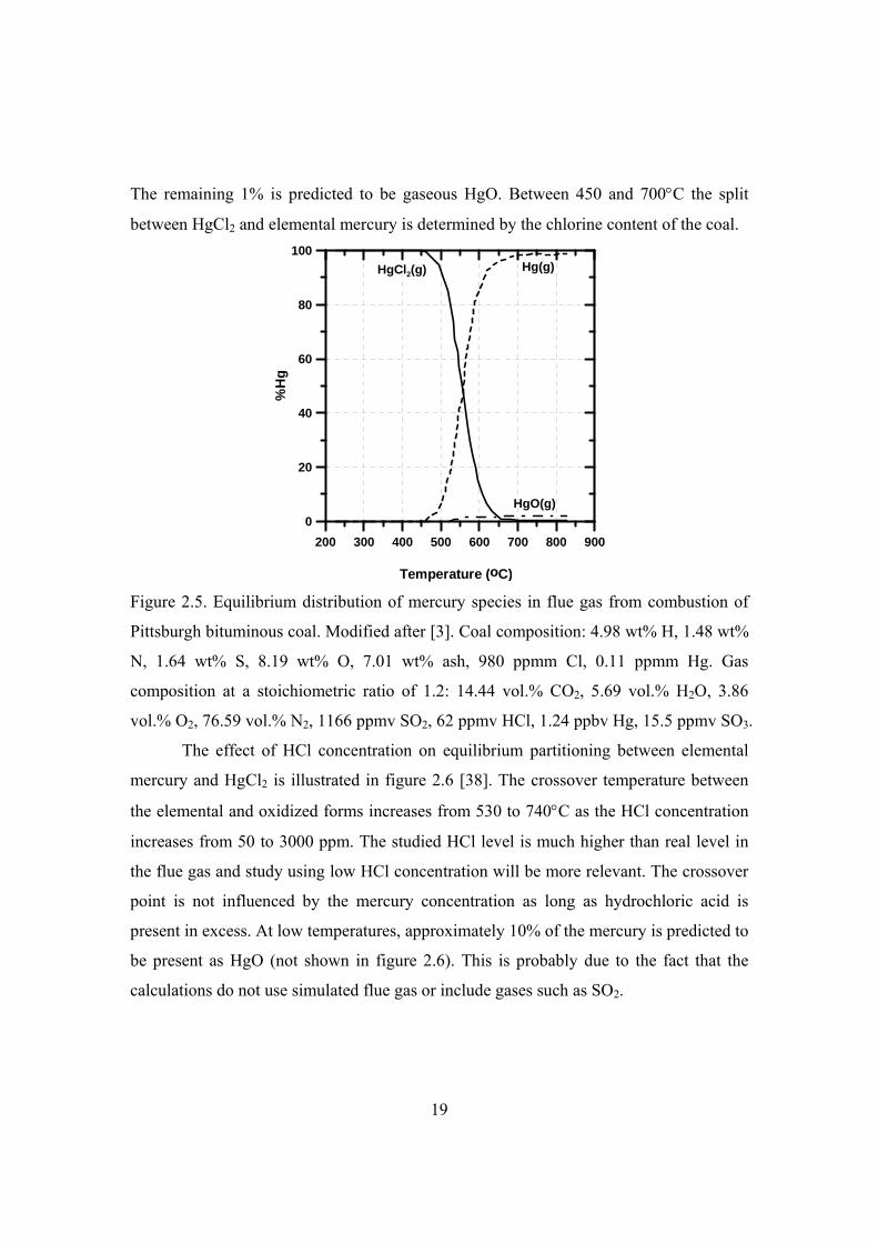
The remaining 1% is predicted to be gaseous HgO. Between 450 and 700C the split
between HgCl2 and elemental mercury is determined by the chlorine content of the coal.
200 300 400 500 600 700 800 900
Temperature (oC)
0
20
40
60
80
100
%H
gHgCl2(g) Hg(g)
HgO(g)
Figure 2.5. Equilibrium distribution of mercury species in flue gas from combustion of
Pittsburgh bituminous coal. Modified after [3]. Coal composition: 4.98 wt% H, 1.48 wt%
N, 1.64 wt% S, 8.19 wt% O, 7.01 wt% ash, 980 ppmm Cl, 0.11 ppmm Hg. Gas
composition at a stoichiometric ratio of 1.2: 14.44 vol.% CO2, 5.69 vol.% H2O, 3.86
vol.% O2, 76.59 vol.% N2, 1166 ppmv SO2, 62 ppmv HCl, 1.24 ppbv Hg, 15.5 ppmv SO3.
The effect of HCl concentration on equilibrium partitioning between elemental
mercury and HgCl2 is illustrated in figure 2.6 [38]. The crossover temperature between
the elemental and oxidized forms increases from 530 to 740C as the HCl concentration
increases from 50 to 3000 ppm. The studied HCl level is much higher than real level in
the flue gas and study using low HCl concentration will be more relevant. The crossover
point is not influenced by the mercury concentration as long as hydrochloric acid is
present in excess. At low temperatures, approximately 10% of the mercury is predicted to
be present as HgO (not shown in figure 2.6). This is probably due to the fact that the
calculations do not use simulated flue gas or include gases such as SO2.

20
Figure 2.6. Equilibrium distribution of elemental mercury and mercury chloride for
different HCl concentrations [38]. Other gas concentrations include 7.4% O2, 6.2% CO2,
12.3% H2O and N2 as balance.
The high levels of mercury oxidation are most strongly correlated with high
chlorine concentrations in the coal [33]. Iron is thought to catalyze the oxidation and
subsequent capture of mercury [30]. Calcium likely reacts with chlorine and sulphur
during the combustion process and thereby reduces its ability to promote the oxidation of
mercury [33]. The high percentages of elemental mercury typically found in emissions
from lignite and subbituminous coal combustion can likely be attributed to their high
calcium and low chlorine contents.
Full-scale measurements showed that elemental mercury was dominant in the
stack of coal-fired power plants, while oxidized mercury was dominant in the stack of
incinerators [34,39]. This could be due to the formation of mercury compounds in
furnaces and APCDs configuration differences between them. For the study of mercury
removal by sorbent injection upstream of dust collectors, it is important to know the
mercury speciation at the APCD inlet rather than at the stack. The data of mercury
speciation in the flue gas at the inlets of APCDs are very scattered [25,40-43]. This is
again due to different parameters that potentially affect the mercury speciation. Therefore,

21
to develop a mercury control system for a specific plant, measurement of the mercury
speciation at the APCDs’ inlet is necessary.
There is disagreement in the publications on the relative importance of mercury
halogenation in the flue gas by chlorine and bromine. Most literatures suggest that
chlorine plays the most important role in oxidation of mercury [30,33]. However,
research by Vosteen et al. [44] shows that the critical species for the halogenation of
mercury in the flue gases is not chlorine, but rather bromine. The stable form of the
halogens at high combustion temperatures are HCl and HBr. On cooling of the gases, the
diatomic and molecular form of the halogens become stable according to the Deacon
type of reactions [33,44]:
2 2 24 2 2HCl O H O Cl (Chlorine-Deacon-reaction) (R2.1)
2 2 24 2 2HBr O H O Br (Bromine-Deacon-reaction) (R2.2)
The kinetics of the bromine-Deacon-reaction is more favorable [33,44]. Moreover,
molecular chlorine is consumed during boiler passage by SO2 through the chlorine
Griffin reaction:
2 2 2 3 2SO Cl H O SO HCl (Chlorine-Griffin-reaction) (R2.3)
In contrast to chlorine, the bromine-Griffin-reaction is not thermodynamically
favored at temperatures above 100C, because the Gibbs free reaction enthalpy of the
bromine-Griffin-reaction is strongly positive within the whole boiler temperature range.
Therefore, SO2 is not consuming Br2 during boiler passage. To summarize, the primary
reason that bromine is a much more effective mercury oxidizer than chlorine is that HBr
dissociates much more extensively into reactive atomic species than HCl at typical post-
flame conditions [45].
The world average Cl contents in coals for bituminous and lignite coals are,
respectively, 340±40 and 120±20 ppm [46]. The typical bromine content in the coal is
about 1-10 ppm [33,44,47]. Although the chlorine content in the coal is far higher than
the bromine content in the coal, the amount of molecular bromine Br2 in the flue gas may
be many times higher than the amount of Cl2 in the flue gas downstream the combustion
zone [44]. Recently, Niksa [45,48] also stated that homogeneous chemistry with bromine

22
species is much faster than with chlorine species because the bromine atom
concentrations at the furnace exit are three to four orders of magnitude greater. There
might be ample supply of Br2 to oxidize the typical amounts of mercury in the coal flue
gases through direct mercury bromination:
22 HgBrBrHg (Direct Hg bromination) (R2.4)
Based on this knowledge, direct bromine injection into the flue gas has been proposed
and patented to enhance mercury capture by fly ash or sorbents, or mercury oxidation
followed by removal in wet flue gas desulphurization (FGD) unit [44,49]. However, the
higher concentration of Br2 in the post-combustion zone is not verified by full-scale
investigation due to the lack of Br2 and Cl2 measurements.
The arguments on the relative importance of mercury adsorption by bromine are
supported by simulation and full-scale demonstration in power plants [45,50].
Simulations with only homogeneous reaction mechanism by Niksa et al. [45] show that
50% mercury oxidation is obtained for a typical thermal history along a power plant gas
cleaning system with 10 ppmv Br in the flue gas. In contrast, no mercury oxidation is
achieved by 20 ppmv HCl in the flue gas. Homogeneous mercury oxidation by bromine
begins as the flue gas cools below 600C and accelerates sharply when the temperature
drops to below 300C. At the furnace exit, bromine atoms are present in concentrations
that are comparable to HBr levels, in contrast to the much lower concentrations of
chlorine atoms at these conditions.
Liu et al. [50] estimated that a 50% mercury oxidation could be obtained by
injecting 52 ppm Br2 in the flue gases without fly ash for a reaction time of 15 s at 137°C.
Laboratory study of Br2 in the simulated flue gas showed that fly ash in the flue gas
significantly promoted the oxidation of Hg0 by Br2 and the unburned carbon in the fly
ash played a major role in the promotion primarily through the rapid adsorption of Br2
[50]. Hg0 oxidation in the gas phase was found to be less important than fly ash-induced
oxidation by Br2. However, there is an increasing concern on the stability of bromine
impregnated in the AC, added to fuels, or injected directly to the flue gas, which could

23
lead to downstream pollution and pipeline corrosion due to the strong acidic nature of
bromine.
2.3.2 Mercury transformation within cement kiln system
Larsen et al. [51] made a thermodynamic calculation of potential mercury species
distribution in a cement kiln preheater. In order to get closer to a preheater environment,
chloride as well as sulphide and sulphate compounds were included in the oxygen-
containing system. Detailed compositions of the solid and flue gas can be found in the
figure caption. The alkaline dust was represented by CaO in the calculations, which is in
excess compared to the acidic components such as HCl and SO2. Figure 2.7 illustrates the
equilibrium distribution of mercury species as a function of temperature when the
mercury input in the solid is in ppmm level. The dominant species below 180°C is
oxidized mercury in forms of HgO and HgCl2, while all mercury compounds
thermodynamically preferred above 200°C are gas-phase species and the main species is
Hg0(g).

24
Figure 2.7. Equilibrium distribution of mercury species as a function of temperature in
the preheater environment with mercury input in the range of ppmm [51].
Thermodynamic calculation input: solid: 5.00 kmol CaO, 0.000025 kmol HgCl2,
0.000025 kmol HgSO4, 0.000025 kmol HgS, 0.000025 kmol Hg, gas: 0.03 kmol HCl, 1
kmol H2O,1 kmol O2, 30.00 kmol CO2, 0.05 kmol SO2, 67.95 kmol N2.
Figure 2.8 illustrates the equilibrium distribution of mercury species as a function
of temperature when the mercury input is in ‰ level. Presence of CaO and HCl are not
included in the calculation assuming that HCl can be captured by large amount CaO in
the cement raw materials. The results are completely different from the calculation with
ppmm level of mercury input in the solid. The dominant species below 200°C is HgSO4,
while a certain amount of HgCl2(g) is formed above 200°C. The HgSO4(g) decomposes
at around 450°C, thus the dominant species above 450°C are Hg0(g) and HgCl2(g).

25
Fig. 2.8. Equilibrium distribution of mercury species as a function of temperature in the
preheater environment with mercury input in the range of ‰ [51]. Thermodynamic
calculation input: solid: 0.025 kmol HgCl2, 0.025 kmol HgSO4, 0.025 kmol HgS, 0.025
kmol Hg, gas: 1 kmol H2O,1 kmol O2,30.00 kmol CO2, 0.05 kmol SO2, 97.95 kmol N2.
General conclusions from thermodynamic calculations for a preheater
representative environment are [51]: HgS will most probably be converted to other
mercury species when entering the preheater, provided the reaction rates are sufficiently
high compared to residence time. Mercury species are preferentially gas-phase
compounds at temperatures above about 400°C. In a CaO rich environment, the
thermodynamically preferred mercury species above 300°C is Hg0(g). This may be
primarily because CaO acts as an HCl drain. Calculation indicates that the
thermodynamically favored mercury species present at the extraction point for a typical
kiln by-pass is Hg0(g).
Detailed experimental information of mercury transformation in cement kiln
system has not been reported. Although cement production also involves combustion, the

26
flue gas composition, temperature and residence time in cement kiln are quite different
from power plants and waste incinerators as explained earlier. When looking at mercury
chemistry in cement kilns, these factors should be taken into consideration.
Schreiber et al. [22] investigated the fate and inherent control of mercury in
cement kiln systems using material balance studies and comprehensive stack tests that
were conducted over the past two decades. They concluded that mercury does not simply
volatilize out from combusted fuels and heated kiln feed materials and leave directly out
of the stack. The cement kiln systems have some inherent ability to control mercury stack
emissions.
Besides adsorption of mercury on the raw material, as shown earlier, new
mercury compounds such as mercury silicates might be formed through reaction of
mercury with silicate in the raw material and exit the system with the clinker product.
The formation of complex silicates in a kiln system is possible due to the high silica
content in the raw feed (typically 13-15 wt.%) and sufficient residence time for reactions
to take place as vaporized mercury cycles through a kiln system. Edgarbaileyite is the
first reported structure to contain both Hg and Si [52,53]. It has the stoichiometry
Hg6Si2O7 with all of the Hg occurring within the structure as (Hg2)2+ dimers. Although
the mineral data of Edgarbaileyite is available, it has not been possible to identify the
thermodynamic properties of the mineral. A chemical equilibrium study was conducted
to estimate probable conditions for the formation of mercury silicates in high temperature
systems [54]. Results from the study suggest that HgSiO3 may form over a temperature
range of 225 to 325°C. However, the equilibrium calculations also indicate that mercury
silicate formation may be inhibited by the presence of chlorine and sulfur. It is reported
by the European cement association that volatile metals are retained in the clinker to a
very small extent only [1]. Unfortunately, there are no laboratory studies to date that
confirm that mercury silicates are stable above temperatures of 325°C. Fundamental
research is required to identify formation of mercury silicates in the cement kiln systems.

27
2.4 Conclusions
Cement plants are quite different from power plants and waste incinerators
regarding the flue gas composition, temperature, residence time, and inherent material
circulation. The flue gas temperature and residence time in a kiln system are much higher
and longer than those in a pulverized coal-fired boiler and waste incinerator. There are
larger water and CO2 contents in the cement kiln flue gas.
In cement production the raw materials contain mercury – often at much higher
levels than in the fuels. The flue gas mercury level is highly dependent on the type of fuel
and raw materials. The mercury concentrations in the flue gas from cement kilns are
typically in the range of 1-50 μg/m3. Instead of fuel, cement raw materials are the
dominant sources of mercury in the cement kiln flue gas. Higher mercury emissions,
however, are observed for cement plants firing waste.
The mercury emissions and speciation from cement kilns can vary over time and
depend on raw materials and fuels used, and process operation. The average mercury
speciation percentages for cement plants with preheater or precalciner not firing waste
are 5% Hgp, 56% Hg2+, 39% Hg0 for raw-mill-on mode, and 4% Hgp, 62% Hg2+, 34%
Hg0 during raw-mill-off mode.
Mercury transformations in combustion flue gas have been investigated
intensively to get an understanding of the transport and fate of mercury into to air
pollution control systems. All forms of mercury in the fuel decompose in the combustion
flame to form Hg0(g), which is oxidized to Hg2+ in the post combustion section. Mercury
halogenation by chlorine and bromine is the dominant mercury transformation
mechanism in coal combustion flue gas. The resulting HgCl2(g) may remain in the flue
gas or adsorb onto inorganic and carbonaceous ash particles entrained in the flue gas
stream. Equilibrium calculations and experiments show that bromine is a much more
effective mercury oxidizer than chlorine.
The cement kiln systems have some inherent ability to retain mercury in the solid
materials. The mercury evaporated from the solids at the hot end of the kiln is carried to
the cold end by the combustion gases. As the flue gas cools, some mercury may

28
adsorb/condense onto dust particles in the cooler regions of the kiln system. When the
plant is running in raw-mill-on mode, the kiln gas containing volatilized mercury is used
to sweep the mill of the finely ground raw feed particles and some mercury is adsorbed
by the fine particulates. However, the adsorbed mercury is either carried back to the kiln
hot zone or added to the kiln system together with the raw meal, thus forming mercury
cycles in the kiln system.
2.5 Further work
There is limited literature regarding mercury characteristics, emissions, and
removal from cement kilns. Essentially all of the published data and information apply to
waste incinerators and coal-fired boilers, all of which have mercury emissions and gas
stream characteristics that are quite different from those from cement kilns. Therefore,
comprehensive studies on mercury chemistry in the cement kiln and mercury removal
from cement plants are imperative.
The inherent recycle of mercury in the kiln system should be further investigated.
The interactions between mercury and cement raw materials play an important role in
understanding of mercury chemistry in the cement kiln system. Research is required to
break the mercury cycle in the kiln system, regenerate and implement beneficial
utilization of removed mercury-contained CKD. These treatment systems minimize net
CKD generation by removing mercury, alkalies and other contaminants and returning
treated dust to the system without compromising product quality.
2.6 References
[1] CEMBUREAU, the European Cement association, Best available technologies for the cement
industry, 1999.
[2] M. Achternbosch, K.R. Bräutigam, M. Gleis, N. Hartlieb, C. Kupsch, U. Richers, P.
Stemmermann, Heavy metals in cement and concrete resulting from the co-incineration of wastes
in cement kilns with regard to the legitimacy of waste utilisation, Wissenschaftliche Berichte,
FZKA 6923, 2003.
[3] C.L. Senior, A.F. Sarofim, T. Zeng, J.J. Helble, R. Mamani-Paco, Gas-phase transformations
of mercury in coal-fired power plants, Fuel Process Technol. 63 (2000) 197-213.

29
[4] D. Shin, S. Choi, J. Oh, Y Chang, Evaluation of polychlorinated dibenzo-p-
dioxin/dibenzofuran (PCDD/F) emission in municipal solid waste incinerators, Environ. Sci.
Technol. 33 (1999) 2657-2666.
[5] K.H. Karstensen, Formation, release and control of dioxins in cement kilns, Chemosphere. 70
(2008) 543-560.
[6] M. V. Seebach and D. Gossman, Cement kilns sources of chlorides not HCl emissions,
http://www.gcisolutions.com/CK&HCL.htm, accessed June 1, 2008.
[7] C. Senior, A. Sarofim and E. Eddings, Behaviour and measurement of mercury in cement
kilns, presented at the IEE-IAS/PCA 45th Cement Industry Technical Conference, Dallas, Texas,
May 4-9 2003.
[8] B. Hall, P. Schager, O. Lindqvist, Chemical-reactions of mercury in combustion flue-gases,
Water Air and Soil Pollution. 56 (1991) 3-14.
[9] Donaldson Membranes, Reducing emissions: Filtering chloride emissions with a bypass cycle,
Filtr. Sep. 45 (2008) 36-37.
[10] H.F. Johnstone, Reactions of sulfur compounds in boiler furnaces, Industrial and
Engineering Chemistry. 23 (1931) 620-624.
[11] A.A. Presto, E.J. Granite, Impact of sulfur oxides on mercury capture by activated carbon,
Environ. Sci. Technol. 41 (2007) 6579-6584.
[12] E. Worrell, L. Price, N. Martin, C. Hendriks, L.O. Meida, Carbon dioxide emissions from
the global cement industry, Annu. Rev. Energy Environ. 26 (2001) 303-329.
[13] C. Senior, C.J. Montgomery, A. Sarofim, Transient model for behaviour of mercury in
Portland cement kilns, Ind Eng Chem Res. 49 (2010) 1436-1443.
[14] Department of Environmental Quality State of Oregon, Ash Grove mercury reduction,
advisory committee’s report, 2007.
[15] L.M. Hills and R.W. Stevenson, Mercury and lead content in raw materials, PCA R&D
Serial No. 2888, 2006.
[16] L.M. Hills, Mercury and lead content in fuels: A literature review, PCA R&D Serial No.
2887, 2006.
[17] S. Sprung, W. Rechenberg, Levels of heavy metals in clinker and cement, Zement-Kalk-
Gips. 47 (1998) 183.
[18] J. Jensen, S. Jepsen, The production, use and quality of sewage sludge in Denmark, Waste
Management. 25 (2005) 239-247.
[19] D. Fytili, A. Zabaniotou, Utilization of sewage sludge in EU application of old and new
methods-A review, Renewable and Sustainable Energy Reviews. 12 (2008) 116-140.
[20] L.E. Åmand, B. Leckner, Metal emissions from co-combustion of sewage sludge and
coal/wood in fluidized bed, Fuel. 83 (2004) 1803-1821.
[21] C. Senior and E. Eddings, Evolution of mercury from limestone, PCA R&D Serial No. 2949,
2006.

30
[22] R.J. Schreiber, C.D. Kellett and N. Joshi, Inherent mercury controls within the Portland
cement kiln system, PCA R&D Serial No. 2841, 2005.
[23] V.C. Johansen and G.J. Hawkins, Mercury speciation in cement kilns: A literature review,
PCA R&D Serial No. 2567, 2003.
[24] R.J. Schreiber and C.D. Kellett, Compilation of mercury emissions data, PCA R&D Serial
No. SN3091, 2009.
[25] Schreiber & Yonley Associates, Mercury emissions test report, Ash Grove Cement
Company Durkee, Oregon, Project No. 060204, 2007.
[26] Scott Learn, Cement plant cuts deal on mercury, http://legacy.lclark.edu/
org/nedc/objects/Ash_Grove.pdf, accessed May 10, 2010.
[27] Ravi Narayan, Mercury monitoring challenges facing the cement industry,
http://www.cemtrex.com/component/content/article/5-monitoring/125-mercury-monitoring-
challenges-facing-the-cement-industry.html, accessed July/22, 2010.
[28] German Cement Works Association, Activity report 1999-2001, 2001.
[29] C. Mones, Removal of elemental mercury from a gas stream facilitated by a non-thermal
plasma device, Final report on jointly sponsored research, task 34 under DE-FC26-98FT40323,
2006.
[30] J.H. Pavlish, E.A. Sondreal, M.D. Mann, E.S. Olson, K.C. Galbreath, D.L. Laudal, S.A.
Benson, Status review of mercury control options for coal-fired power plants, Fuel Processing
Technology. 82 (2003) 89-165.
[31] T.R. Carey, C.F. Richardson, R. Chang, F.B. Meserole, M. Rostam-Abadi, S. Chen,
Assessing sorbent injection mercury control effectiveness in flue gas streams, Environ. Prog. 19
(2000) 167-174.
[32] E.G. Pacyna, J.M. Pacyna, F. Steenhuisen, S. Wilson, Global anthropogenic mercury
emission inventory for 2000, Atmospheric Environment. 40 (2006) 4048-4063.
[33] K.C. Galbreath, C.J. Zygarlicke, Mercury transformations in coal combustion flue gas, Fuel
Processing Technology. 65-66 (2000) 289-310.
[34] K.S. Park, Y.C. Seo, S.J. Lee, J.H. Lee, Emission and speciation of mercury from various
combustion sources, Powder Technology. 180 (2008) 151-156.
[35] R.H. Perry, D.W. Green, J.O. Maloney, (Eds.), Perry’s chemical engineers’ handbook, 7th
Ed. The McGraw-Hill Companies, Inc., 1997.
[36] Wikipedia, Category: Mercury compounds, http://en.wikipedia.org/wiki/Category:
Mercury_compounds, accessed September 8, 2010.
[37] F. Frandsen, K. Dam-Johansen, P. Rasmussen, Trace elements from combustion and
gasification of coal—An equilibrium approach, Progress in Energy and Combustion Science. 20
(1994) 115-138.
[38] R.N. Sliger, J.C. Kramlich, N.M. Marinov, Towards the development of a chemical kinetic
model for the homogeneous oxidation of mercury by chlorine species, Fuel Process Technol. 65-
66 (2000) 423-438.

31
[39] A. Licata, R. Beittel and T. Ake, Multi-pollutant emissions control & strategies: Coal-fired
power plant mercury control by injecting sodium tetrasulfide, Institutes of Clean Air Companies
(ICAC) Forum 2003, Nashville, TN, October 14-15, 2003.
[40] S.J. Lee, Y. Seo, H. Jang, K. Park, J. Baek, H. An, K. Song, Speciation and mass distribution
of mercury in a bituminous coal-fired power plant, Atmospheric Environment. 40 (2006) 2215-
2224.
[41] X. Yang, Y. Zhuo, Y. Duan, L. Chen, L. Yang, L. Zhang, Y. Jiang, X, Xu, Mercury
speciation and its emissions from a 220 MW pulverized coal-fired boiler power plant in flue gas,
Korean Journal of Chemical Engineering. 24 (2007) 711-715.
[42] S. Tang, X. Feng, J. Qiu, G. Yin, Z. Yang, Mercury speciation and emissions from coal
combustion in Guiyang, southwest China, Environmental Research. 105 (2007) 175-182.
[43] M.B. Chang, H.T. Wu, C.K. Huang, Evaluation on speciation and removal efficiencies of
mercury from municipal solid waste incinerators in Taiwan, The Science of The Total
Environment. 246 (2000) 165-173.
[44] B.W. Vosteen, R. Kanefke, H. Köser, Bromine-enhanced mercury abatement from
combustion flue gases-Recent industrial applications and laboratory research, VGB PowerTech.
86 (2006) 70.
[45] S. Niksa, C.V. Naik, M.S. Berry, L. Monroe, Interpreting enhanced Hg oxidation with Br
addition at Plant Miller, Fuel Process Technol. 90 (2009) 1372-1377.
[46] Y.E. Yudovich, M.P. Ketris, Chlorine in coal: A review, International Journal of Coal
Geology. 67 (2006) 127-144.
[47] S.V. Vassilev, G.M. Eskenazy, C.G. Vassileva, Contents, modes of occurrence and origin of
chlorine and bromine in coal, Fuel. 79 (2000) 903-921.
[48] S. Niksa, B. Padak, B. Krishnakumar, C.V. Naik, Process Chemistry of Br Addition to
Utility Flue Gas for Hg Emissions Control, Energy Fuels. 24 (2010) 1020-1029.
[49] M. Holmes and J. Pavlish, Mercury information clearinghouse, Quarter 3- Advanced and
developmental mercury control technologies, July 2004.
[50] S. Liu, N. Yan, Z. Liu, Z. Qu, H.P. Wang, S. Chang, M. Charles, Using bromine gas to
enhance mercury removal from flue gas of coal-fired power plants, Environ. Sci. Technol. 41
(2007) 1405-1412.
[51] M.B. Larsen, I. Schmidt, P. Paone, J. Salmento, A. Petersen and A.W. Jørgensen, Mercury
in cement production-A literature review, FLSmidth internal report, 2007.
[52] R.J. Angel, G. Cressey, A. Criddle, Edgarbaileyite, Hg6Si2O7: The crystal structure of the
first mercury silicate, American Mineralogist. 75 (1990) 1192.
[53] A.C. Robert, M. Bonardi, Erd, Richard C, Edgarbaileyite: the first known silicate of mercury,
from California and Texas, The Mineralogical Record. 21 (1990) 215.
[54] T.M. Owens, C.Y. Wu, P. Biswas, An equilibrium analysis for reaction of metal compounds
with sorbents in high temperature systems, Chem. Eng. Commun. 133 (1995) 31-52.

32
3
Review of technologies for mercury removal from
flue gas
This chapter reviews the available technologies for mercury removal from flue
gas, and the applicability of the technologies in cement plant is discussed. Focus is put on
mercury removal by sorbent injection. Tests of sorbents in lab-scale fixed-bed reactors,
slipstream pilot-scale reactors and full-scale plants are reported.
3.1 Introduction
The options for mercury control include mercury avoidance by coal and raw
material cleaning, mercury removal by sorbent injection upstream of existing air
pollution control devices (APCDs), and enhanced mercury removal by oxidation.
Differences in fuel type and composition and pollution control devices make it necessary
to develop customized solutions for each plant. The suitable mercury control method for
a specific plant depends on the plant’s configuration, fuel types, and existing flue gas
controls used for other pollutants. In addition, the complicated chemistry and multiple
mechanisms governing mercury speciation in combustion facilities makes it necessary to
investigate mercury emission control technologies at conditions relevant to each specific
plant [1]. Mercury control technologies applied in power plants and waste incinerators
are reviewed in this section and the applicability of these technologies in cement plants is
discussed.

33
3.2 Mercury avoidance technology
3.2.1 Coal cleaning
Physical coal cleaning is used primarily to reduce the ash and pyritic sulfur
content of coal [2-4]. Approximately 75% of the U.S. Eastern and Midwestern
bituminous coals undergo physical coal cleaning prior to shipment to power plants. Less
than 20% of the western coals, such as Powder River basin (PRB) coal and Colorado
bituminous coals, are cleaned [5].
Ash and pyritic sulfur are removed due to the difference in the densities of these
materials compared to the organic constituents in the coal. Mercury present in a sulfide
form also has a high density and can be removed during physical coal cleaning.
Reduction in mercury levels in coals ranging from 10% up to 78% have been reported
[3,6,7]. The average mercury reduction resulting from physical coal cleaning is estimated
to be in the range of 20% to 37% [6,8]. The cost of waste water treatment is very high.
As most of the mercury is from the raw material in cement production, the extent of
mercury removal through coal cleaning is expected to be very limited.
3.2.2 Cement raw material cleaning
Two methods are proposed in the patents for removing mercury from cement raw
materials, i.e., washing and gasification prior to feeding to the kiln [9,10]. By water
washing the water-soluble mercury in the raw materials is removed. In the gasification
process, raw materials are introduced into a heating furnace and mercury and its
compounds contained in the raw materials are gasified. The resulting gas is introduced
into an activated carbon adsorption tower, mercury and its compounds are adsorbed and
separated. However, no results on the mercury removal efficiency by raw material
cleaning are reported in the publications. Due to large amount of raw materials applied in
the cement production, the cost of raw material cleaning is expected to be extremely high
and this technology appears not suitable for mercury removal from cement plants.

34
3.2.3 Fuel switching
The use of tire-derived fuels (TDF) and substitution of coal and petroleum coke
with natural gas could potentially result in a modest reduction in the mercury emissions
due to the replacement of mercury-containing fossil fuels with low mercury fuels. Co-
firing of TDF with a subbituminous coal in a 55 kw pilot-scale pulverized coal
combustor had a significant effect on mercury speciation in the flue gas [11]. With 100%
coal firing, there was only 16.8% oxidized mercury in the flue gas compared to 47.7%
when 5 wt.% TDF was co-fired and 84.8% when 10% TDF was co-fired. The
significantly enhanced mercury oxidation may be the result of additional homogeneous
gas phase reactions between elemental mercury and the additional chlorine from TDF
combustion. The chlorine content in TDF is about 600 ppmm. However, co-firing of
TDF in the pilot-scale combustor with a hybrid filter for mercury removal demonstrated
only limited improvement on mercury-emission control by the hybrid filter without
sorbent injection. The enhanced mercury oxidation from co-firing TDF has potential in
mercury emission control for power plants equipped with a wet flue gas desulphurization
unit, since oxidized mercury is easily captured in the scrubber. Typically, kilns using
TDF have a replacement rate no greater than 30% of the total fuel requirement. Richards
et al. [12] summarized the available air emissions data for cement plants firing TDF and
literature applicable to cement kilns and concluded that the variability in mercury
concentrations and speciation overshadowed any beneficial impact on emissions due to
the firing of TDF.
Natural gas firing in boilers that are presently being fired with coal results in
direct and significant reductions in mercury. However, as mentioned previously the fuel
is usually not the dominant source of mercury in cement kiln flue gas. The limestone and
possibly other raw materials in the kiln feed provide most of the mercury that is
evaporated and emitted. Accordingly, the substitution of solid fuels would have only
limited impact.

35
3.3 Mercury removal by powdered activated carbon injection
Powdered activated carbon (PAC) injection systems are well established as
commercial air pollution control processes for a variety of volatile organic compounds,
dioxin-furan, and heavy metals control applications [5]. The following three versions of
PAC processes are being considered for widespread use in coal-fired power plants [6]: (1)
PAC injection upstream of the existing dust collector system; (2) Gas cooling followed
by PAC injection upstream of the existing dust collector system; (3) Gas cooling of the
effluent gas stream of the existing dust collector system followed by PAC injection
upstream of a second dust collector for removal of the adsorbent.
The activated carbon particles remain suspended in the moving gas stream for
periods of one to three seconds. They then deposit onto the dust cake formed on the filter
bags. Additional mercury capture takes place when the mercury-containing gas stream
passes through the sorbent-containing dust cake. Electrostatic precipitators (ESPs) are
rarely used as the downstream polishing dust collector because the precipitated activated
carbon is partially isolated from the gas stream once it reaches the collection plate
surface.
3.3.1 Parameters affecting mercury removal by activated carbon
injection
There are a large number of variables that affect the adsorption of mercury on
powdered activated carbon. These include [5]: mercury speciation and concentration,
sorbent physical and chemical properties such as particle size distribution, pore structure
and distribution, and surface characteristics, gas temperature, flue gas composition,
sorbent concentration, mercury-sorbent contact time, and adequacy of sorbent dispersion
into the mercury containing gas stream.
Due to the differences of these variables among plants, there are large variations
in the reported PAC injection rates and mercury removal efficiencies in various studies
and commercial systems [13]. Therefore, it does not make sense to compare the mercury
36
removal efficiencies and sorbent injection rates without considering the actual conditions
in the specific plants.
Mercury speciation determines the mercury capture capacity of sorbents at a
given temperature. Pavlish and others [13] concluded that virgin activated carbon has a
higher rate of capture for mercuric chloride than for elemental mercury. Ho and others
[14] reported that sulphur-impregnated activated carbons have enhanced rates of
elemental mercury capture.
Pavlish et al. [13] conducted a detailed review on possible rate-controlling
mechanisms for mercury removal by sorbent injection. The overall reaction rates may be
limited by mass transfer from the bulk gas to the sorbent surface, the equilibrium
adsorption capacity, and the rates of reactions occurring on the sorbent surface.
All adsorption processes, especially those dependent on physisorption operate
more effectively at low temperatures due to the large adsorption capacity at low
temperatures. Adsorption processes for flue gas cleaning usually are operated in the
temperature range of 150°C to 200°C. The pilot plant studies of PAC injection indicate
that the mercury removal efficiency is strongly dependent on the gas temperatures [5].
Efficiencies of 10% to 70% have been measured at 170°C, and removals of 90% to 99%
have been measured at 100°C. Mercury capture takes place by both physisorption and
chemisorption [13]. With increasing temperature, physical adsorption decreases due to
the nature of exothermal adsorption process whilst chemisorption might be enhanced on
kinetics [15].
Mercury competes with a variety of gases for the adsorption sites on the activated
carbon. Water vapor is important because it is present at concentrations many orders of
magnitude above mercury. At moisture levels above 5% to 10%, moisture competition
can be significant. There are indications that high moisture levels in the flue gas will
suppress the capture of mercury by activated carbon [5,16]. It was postulated that water
molecules are able to fill micropores, thereby blocking adsorption sites for mercury.
Although it is agreed that water plays an important role in the mechanism of
mercury capture, there is disagreement in the literature about the effect of water on

37
mercury removal. Pavlish et al. [13] reported that reintroducing water into flue gas in a
lab-scale reactor at 135C after a period of sorption testing on dry flue gas resulted in an
immediate release of mercury from the activated carbon. However, in another lab-scale
study [17] the presence of moisture on the carbon surface was reported to promote
mercury bonding. About 75–85% reduction in Hg0 adsorption capacity was observed
when the carbon samples’ moisture at a level of 2 wt.% was removed by heating at
110C prior to the Hg0 adsorption experiments at room temperature. These observations
suggest that the moisture adsorbed on activated carbons plays a critical role in retaining
Hg0. It was postulated that adsorbed H2O is closely associated with surface oxygen
complexes and the removal of the H2O from the carbon surface by low-temperature heat
treatment reduces the number of active sites that can chemically bond Hg0 or eliminates
the reactive surface conditions that favor Hg0 adsorption [17]. Liu et al. [18] found that
the mercury adsorption capacity of sulfur impregnated activated carbon did not change
significantly when 5 vol.% water was added to the dry gas at 140C, however, the
adsorption capacity decreased 25% when the water content in the gas increased to 10
vol.%. These observations indicate that it is important to investigate the sorbent using the
same water vapor content as in the full-scale plant flue gas or in a wide range of moisture
content. Further investigations of the effect of water on mercury adsorption are desired to
reveal the dominating effects.
Miller et al. [19] and Ochiai et al. [20] conducted full factorial design
experiments in fixed-bed reactors to determine the relative effects of SO2, HCl, NO, and
NO2 on the elemental mercury capture ability of commercial activated carbons. Without
acid gases present, upon exposure to a baseline gas mixture of 6% O2, 12% CO2, 8%
H2O, and N2, the lignite activated carbon sorbent provided only about 10–20% initial
mercury capture of Hg0 for about 30 min and then fast breakthrough at 107°C [19,20].
Adding 50 ppmv HCl alone with the baseline gas improves the mercury adsorption
significantly [19,20]. It was also found out that adding NO or NO2 alone with the
baseline gas also improves the mercury adsorption capacity significantly. The mercury
capture increases from 10-20% for about 30 min using the baseline gas to 90-100% for
38
more than 2-6 h when 300 ppmv NO or 20 ppmv NO2 was added one at a time to the
baseline gases at 107°C.
When 1600 ppmv SO2 is added to the baseline gas the mercury adsorption
capacity will not be changed or only improved slightly [19,21]. Addition of 20 ppm SO3
to the gas reduced mercury capture by nearly 80%, and higher SO3 concentrations led to
further reductions in the mercury capture [21-23]. The competition between SO3 and
mercury for binding sites on the surface of activated carbon decreases the mercury
adsorption capacity.
The combination of 1600 ppmv SO2 and 20 ppmv NO2 additions resulted in
significant different mercury breakthrough profile compared to adding NO2 alone [19,20].
A highly significant interaction between SO2 and NO2 caused a rapid breakthrough of
mercury and is the controlling mechanism responsible for poor sorbent performance. The
detailed mechanism of SO2 and NO2 interaction is presented in section 3.3.5.2.
3.3.2 Tests of mercury sorbents in labscale fixedbed reactors
A good sorbent is expected to have high mercury adsorption capacity and fast
kinetics. A sorbent with good capacity but slow kinetics is not a good choice as it takes
mercury compound molecules too long time to reach the particle interior [24]. On the
other hand, a sorbent with fast kinetics but low capacity is not good either as a large
amount of sorbent is required for a given mercury removal. To satisfy these two
requirements, the sorbent must have a reasonably high surface area or micropore volume
and a pore network of relatively large pores for the transport of molecules to the interior.
3.3.2.1 Carbonbased sorbents
As mentioned previously mercury capture is very sensitive to the flue gas
composition and temperature, and for this reason only the mercury capture capacities of
sorbents tested under simulated flue gas conditions are reported and compared here.
Extensive research has been conducted to study the sorbent mercury capture capacity
mainly using lab-scale fixed-bed reactors [25-36]. The mercury sorbents can be divided

39
into three groups, i.e., virgin carbon sorbents, chemically treated carbons, and non-
carbon based sorbents. The majority of the publications focused on elemental mercury
capture and only few studies investigated capture of HgCl2.
Typical properties of selected sorbents are reported in table 3.1. Coal source and
ash content relate to the composition of the coal and characterize the state of the carbon
such as fixed carbon/volatile ratio [37,38]. High ash content reduces the overall activity
of the activated carbon. Particle surface area is a measure of adsorption capacity and
describes the available surface for mercury adsorption. Pore size and distribution is an
indicator of sorbent quality, with smaller pores preferred. Particle size is used to describe
the degree of sorbent physical preparation. The mean particle size and distribution of
particle size are important parameters for evaluating mercury removal rate and pressure
drop. Smaller size provides faster rate of adsorption and results in larger pressure drop.
Content of bromine/chlorine/sulfur is considered as an indicator of the chemical
characteristics of sorbent responsible for mercury adsorption. Bulk density reflects a
gross approximation of the processing or surface area of a given carbon. The most
investigated sorbents in the literature is Darco FGD, which is a commercial lignite based
powdered activated carbon and is developed for heavy metal removal from incinerators
and power plants.
Table 3.1. Properties of selected sorbents.
Sorbents Sources Ash (wt%)
Sulfur (wt%)
Surface area (m2/g)
Pore volume (cm3/g)
Average pore size (nm)
Mass mean particle size(µm)
Bulk density (g/cm3)
Porosity Reference
Norit Darco FGD
Lignite coal 28.2-32.1
0.86-1.1
481-600
0.535-0.610
3.2 6.8-15 0.51 0.49-0.58
[25-27,29-32,35,39]
Norit Darco Insul
Lignite coal, based on Darco FGD, fine, chemically treated
700 6 0.32 [33,34]
Norit Darco Hg
Lignite coal 1.2 600 16-19 0.51 [40,41]
Norit Darco Hg-LH
Lignite coal, bromine treated
1.2 550 16-19 0.60 [41,42]
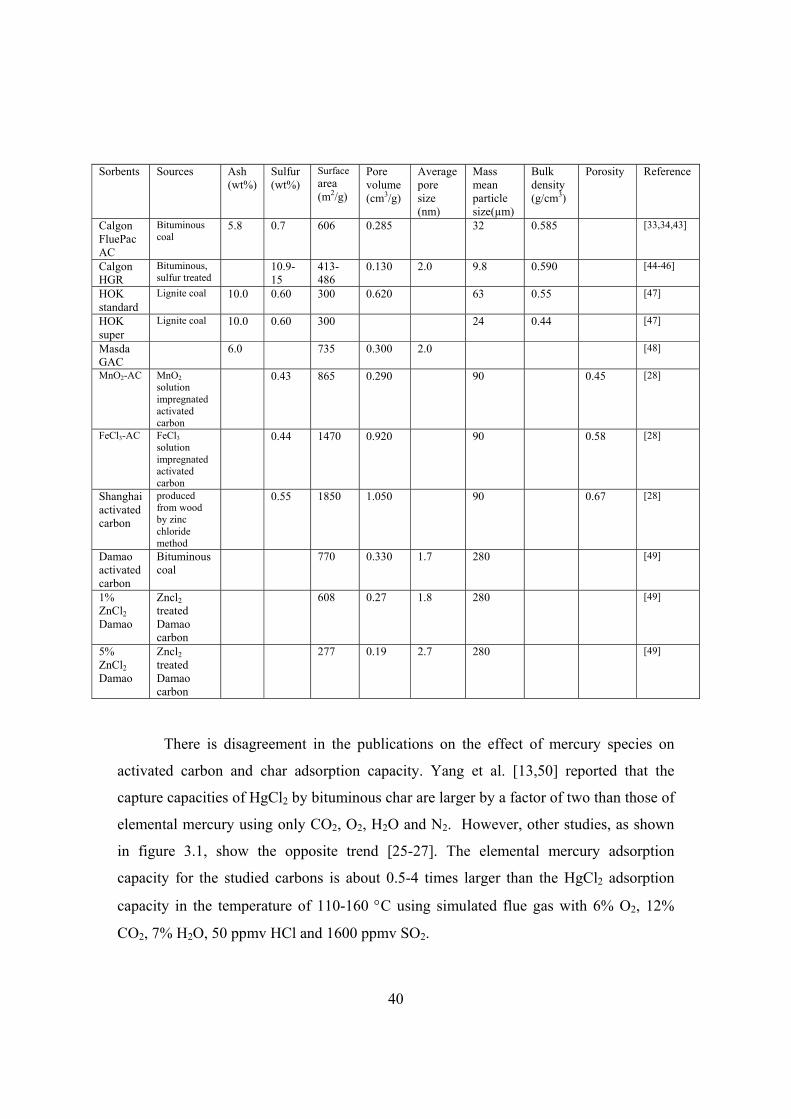
40
Sorbents Sources Ash (wt%)
Sulfur (wt%)
Surface area (m2/g)
Pore volume (cm3/g)
Average pore size (nm)
Mass mean particle size(µm)
Bulk density (g/cm3)
Porosity Reference
Calgon FluePac AC
Bituminous coal
5.8 0.7 606 0.285 32 0.585 [33,34,43]
Calgon HGR
Bituminous, sulfur treated
10.9-15
413-486
0.130 2.0 9.8 0.590 [44-46]
HOK standard
Lignite coal 10.0 0.60 300 0.620 63 0.55 [47]
HOK super
Lignite coal 10.0 0.60 300 24 0.44 [47]
Masda GAC
6.0 735 0.300 2.0 [48]
MnO2-AC MnO2 solution impregnated activated carbon
0.43 865 0.290 90 0.45 [28]
FeCl3-AC FeCl3 solution impregnated activated carbon
0.44 1470 0.920 90 0.58 [28]
Shanghai activated carbon
produced from wood by zinc chloride method
0.55 1850 1.050 90 0.67 [28]
Damao activated carbon
Bituminous coal
770 0.330 1.7 280 [49]
1% ZnCl2 Damao
Zncl2 treated Damao carbon
608 0.27 1.8 280 [49]
5% ZnCl2 Damao
Zncl2 treated Damao carbon
277 0.19 2.7 280 [49]
There is disagreement in the publications on the effect of mercury species on
activated carbon and char adsorption capacity. Yang et al. [13,50] reported that the
capture capacities of HgCl2 by bituminous char are larger by a factor of two than those of
elemental mercury using only CO2, O2, H2O and N2. However, other studies, as shown
in figure 3.1, show the opposite trend [25-27]. The elemental mercury adsorption
capacity for the studied carbons is about 0.5-4 times larger than the HgCl2 adsorption
capacity in the temperature of 110-160 C using simulated flue gas with 6% O2, 12%
CO2, 7% H2O, 50 ppmv HCl and 1600 ppmv SO2.

41
0
500
1000
1500
2000
2500
3000
Ad
so
rpti
on
cap
aci
ty,
g H
g/H
gC
l 2/g
-car
bo
n
45
g/m
3 H
g0 ,
Dar
co F
GD
[26
, 27]
54 g
/m3
Hg
0 ,la
b A
C f
rom
hig
h S
co
al [
25]
59
g/m
3 H
g0 ,
Dar
co F
GD
[25
]
60 g
/m3
Hg
Cl 2
,Dar
co F
GD
[2
5]
61
g/m
3 H
gC
l 2,la
b A
C f
rom
hig
h S
co
al [
25]
Figure 3.1. Effect of mercury speciation on mercury adsorption capacity on activated
carbon. Adsorption temperature is 135C and data are from [25-27]. Simulated flue gas
with 6% O2, 12% CO2, 7% H2O, 50 ppmv HCl and 1600 ppmv SO2.
Generally, the mercury adsorption capacities of carbon sorbents decrease when
the gas temperature is increased [13,50]. However, tests of Darco FGD at 100-135C
(see figure 3.2) from different studies are not in agreement with the trend. This is
probably due to the short exposure time for the test at 100C and the presence of SO3 in
the simulated gas for test at 120C. The adsorption capacity at 100C was measured after
2 h and before the complete breakthrough, while other tests were run until the complete
breakthrough of the sorbent bed was obtained. As discussed previously, the presence of
SO3 in the flue gas will decreases the sorbents’ mercury adsorption capacity. This
observation again illustrates the difficulty of analyzing the results from different studies
that are not conducted under the same conditions.
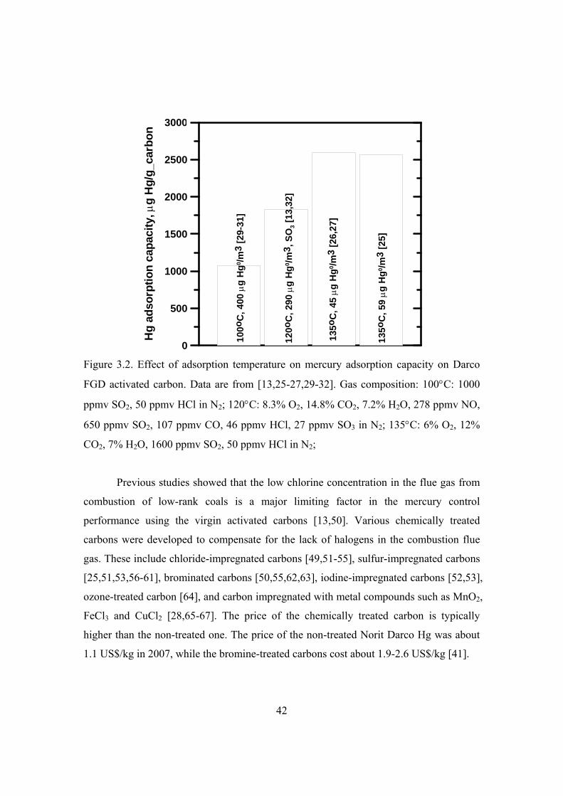
42
0
500
1000
1500
2000
2500
3000
Hg
ad
sorp
tio
n c
apac
ity,
g
Hg
/g_c
arb
on
100
oC
, 40
0 g
Hg
0 /m
3 [2
9-31
]
120
oC
, 29
0 g
Hg
0 /m
3 , S
O3 [
13,3
2]
135
oC
, 45
g
Hg
0/m
3 [2
6,27
]
135
oC
, 59
g
Hg
0/m
3 [2
5]
Figure 3.2. Effect of adsorption temperature on mercury adsorption capacity on Darco
FGD activated carbon. Data are from [13,25-27,29-32]. Gas composition: 100C: 1000
ppmv SO2, 50 ppmv HCl in N2; 120C: 8.3% O2, 14.8% CO2, 7.2% H2O, 278 ppmv NO,
650 ppmv SO2, 107 ppmv CO, 46 ppmv HCl, 27 ppmv SO3 in N2; 135C: 6% O2, 12%
CO2, 7% H2O, 1600 ppmv SO2, 50 ppmv HCl in N2;
Previous studies showed that the low chlorine concentration in the flue gas from
combustion of low-rank coals is a major limiting factor in the mercury control
performance using the virgin activated carbons [13,50]. Various chemically treated
carbons were developed to compensate for the lack of halogens in the combustion flue
gas. These include chloride-impregnated carbons [49,51-55], sulfur-impregnated carbons
[25,51,53,56-61], brominated carbons [50,55,62,63], iodine-impregnated carbons [52,53],
ozone-treated carbon [64], and carbon impregnated with metal compounds such as MnO2,
FeCl3 and CuCl2 [28,65-67]. The price of the chemically treated carbon is typically
higher than the non-treated one. The price of the non-treated Norit Darco Hg was about
1.1 US$/kg in 2007, while the bromine-treated carbons cost about 1.9-2.6 US$/kg [41].

43
Chlorine impregnation of a virgin activated carbon using dilute solutions of
hydrogen chloride leads to increases in fixed-bed capture of both elemental mercury and
mercuric chloride by a factor of 2-3 for a simulated flue gas without HCl, but with 7.1%
O2, 6.9% H2O, 3.4% CO2, 4.5 ppmv CO, 200 ppmv NOx and 500 ppmv SO2 [51]. It is
not reported how the chlorine impregnated carbon behaviors if HCl is present in the gas.
Coal-derived activated carbon from high-organic-sulfur coals was reported to
have a greater equilibrium Hg0 adsorption capacity than that prepared from low-organic-
sulfur coal when tested using a simulated flue gas with 6% O2, 7% H2O, 12% CO2, 50
ppmv HCl, and 1600 ppmv SO2 [25]. At 135C the equilibrium Hg0 adsorption capacity
of carbon derived from high-organic-sulfur coal, which contained 3.7 wt % total sulfur
and 2.9 wt% organic sulfur is 2718 µg Hg0/g_carbon, on the other hand the equilibrium
Hg0 adsorption capacity of carbon prepared from low-organic-sulfur coal with 1.2 wt%
total sulfur and 0.7 wt% organic sulfur was only 1304 µg Hg0/g_carbon. When the low-
organic-sulfur coal-derived activated carbon is impregnated with elemental sulphur at
600°C, its equilibrium Hg0 adsorption capacity is comparable to the adsorption capacity
of the activated carbon from the high-organic-surfur coal. Elemental sulphur-
impregnated carbons enhance elemental mercury removal due to the formation of
mercury sulphide on the carbon surface [68]. A portion of the inherent organic sulphur
in the starting coal, which remained in the activated carbon, plays an important role in
adsorption of elemental mercury. Besides organic sulphur, the surface area and
micropore area of the activated carbon also influence Hg0 adsorption capacity [25]. The
HgCl2 adsorption capacity is not as dependent on the surface area and concentration of
sulphur in the activated carbon as for adsorption of Hg0.
Another method for modifying carbon surfaces is oxidation, using reagents that
include oxygen, ozone, hydrogen peroxide, nitric acid, and permanganate [64]. Ozone
treatment of carbon surfaces leads to large increases in the elemental mercury capture
capacity by more than a factor of 100 when tested in Argon gas, but the activity is easily
destroyed by exposure to air, to water vapor, or by mild heating at 120C [64]. Freshly
ozone-treated carbon surfaces are shown to form labile C–O containing oxidizing groups,

44
which are likely to be epoxides or secondary ozonides. However, this ability fades with
aging. The finding opens the possibility of in-situ carbon ozonolysis to create fresh,
super-active sorbents with the additional benefit of sorbent hydrophilicity useful in
certain applications. Ozone treatment of fly ash carbon has been reported to inhibit the
adsorption of commercial surfactants in concrete paste, thus mitigating the known
negative effects of carbon on ash utilization [69-73]. Therefore, the enhanced mercury
removal could be a co-benefit of the ozone treatment.
3.3.2.2 Noncarbon sorbents
For cement plant application a non-carbon sorbent is more attractive if the used
sorbent can be added to the final cement product or can be separated and regenerated.
Carbon can deteriorate the cement quality if the used carbon is not separated from the
cement materials by installing an expensive polishing filter. As inspiration to cement
plant application, research on development of non-carbon sorbents that do not adversely
impact sales of fly ash as a coal combustion byproduct for Portland cement and concrete
production are reported in this section.
Chemically synthesized manganese oxides powder has been demonstrated in
power plants to remove mercury, NOx and SO2 from flue gas [74-77]. The reacted
sorbent can be regenerated by a wet chemical process if the sorbent is injected just before
the added polishing fabric filter [74-77]. The simplified capture reactions for these
pollutants are suggested as following:
02Hg + MnO Mn*Hg complex (R3.1)
x 2 3 2NO + MnO Mn(NO ) (R3.2)
x 2 4SO + MnO MnSO (R3.3)
Non-carbonaceous materials or mineral oxides including silica gel, alumina,
molecular sieves, zeolites, and montmorillonite have been modified with various
functional groups such as amine, amide, thiol, urea, and additives such as elemental
sulfur, sodium sulfide, and sodium polysulfide to examine their potential as sorbents for
the removal of mercury vapor at coal-fired utility power plants [78]. A number of sorbent
45
candidates such as amine-silica gel, urea-silica gel, thiol-silica gel, amide-silica gel,
sulfur-alumina, sulfur-molecular sieve, sulfur-montmorillonite, sodium sulfide-
montmorillonite, and sodium polysulfide-montmorillonite, were synthesized and tested in
a lab-scale fixed-bed system under an argon flow for screening purposes at 70°C and
140°C. Several functionalized silica materials used for effective control of heavy metals
in the aqueous phase showed insignificant adsorption capacities for mercury control in
the gas phase, suggesting that mercury removal mechanisms are different in these two
phases. Among the synthesized samples, sodium polysulfide-impregnated
montmorillonite showed a moderate adsorption capacity at 70°C.
The commercial Amended Silicates sorbent uses silicate minerals as substrate
particles on which a chemical reagent with a strong affinity for mercury and mercury
compounds is impregnated [79,80]. A phyllosilicate substrate, for example, vermiculite
or montmorillonite, is used as an inexpensive support to a thin layer for a polyvalent
metal sulfide, ensuring that more of the metal sulfide is engaged in the sorption process.
The sorbent is prepared by ion exchange between the silicate substrate material and a
solution containing one or more of a group of polyvalent metals including tin, iron,
titanium, manganese, zirconium, and molybdenum. Controlled addition of sulfide ions to
the exchanged silicate substrate produces the sorbent. The silicates provide a low-cost
substrate material with average particle size of a few microns and extended surface area
for the amendment process. Due to their high silicate content, they have been proven
compatible with the continued sale of fly ash as a pozzolan material for concrete and
cement production. The price of the Amended Silicates sorbent is about 2.2-4.4 US$/kg
[81], which is comparable to the price of the chemically treated carbons [41]. However,
the performance data of the Amended Silicates sorbent are rarely reported due to the
concern of intelligent property.
A comparison between Darco FGD activated carbon and Ca(OH)2 indicated that
non-carbon-based sorbents with relatively high Ca contents can be fairly effective HgCl2
sorbents [29,30]. The Ca-based sorbents exhibited HgCl2 removal as high as half of the
removal shown by the Darco FGD activated carbon when 100 mg sorbent was tested in a

46
bench-scale fixed-bed reactor using simulated flue gas containing 10% CO2, 7% O2, 5%
H2O, and 173 ppmv SO2 [29,30]. However, the carbon-based sorbent showed superior
efficiency of elemental removal compared to Ca-based sorbent.
Full-scale investigations in coal-fired power plants have observed mercury
capture by unburned carbon in the fly ash [82]. Mercury removal by fly ash has also been
extensively studied to find a solution to the expensive mercury sorbents [36,83-87]. As
shown in figure 3.3, the amount of carbon in the fly ash has a strong effect on mercury
adsorption capacity of the fly ash. The mercury adsorption capacity increases with
carbon content in the fly ash, however, it is not directly proportional to the carbon
content. The mercury adsorption capacity of Nixon fly ash with 2% residual carbon is
about 30% of the commercial activated carbon Darco G60 [86].
0 10 20 30 40
Carbon content in the fly ash (%)
0
100
200
300
400
500
600
700
800
900
Ad
sorb
ed H
g (
g H
g/1
06 g
ash
) Nixon, 2% CCherokee, 8.7% CClark, 32.7% CHuntington, 35.9% C
Figure 3.3. Mercury adsorption capacity on fly ashes with different carbon content. Data
are from [86]. The applied adsorption temperature is 121C and elemental mercury
concentration is 4 mg/m3 with nitrogen as balance gas.
Dunham et al. [85] investigated 16 fly ash samples from a variety of sources and
coal types in a fixed-bed reactor at 121-177C using elemental mercury or HgCl2 in
simulated flue gas mixtures of O2, SO2, NO, NO2, H2O and HCl. While many of the ash

47
samples oxidized elemental mercury to HgCl2 in a range of 15-85%, not all of the
samples that oxidized mercury also captured elemental mercury. However, no capture of
elemental mercury was observed without accompanying oxidation. In general, oxidation
of elemental mercury increased with increasing amount of magnetite (Fe3O4) in the ash.
However, one high-carbon subbituminous ash with no magnetite showed considerable
mercury oxidation that may have been due to the carbon. Dunham et al. [85] suggested
that an iron oxide with a spinel-type structure is active in fly ash with respect to mercury
oxidation. Surface area as well as the nature of the surface, such as the oxygen
functionality and presence of halogen species appeared to be important for oxidation and
adsorption of elemental mercury. For the applied gas composition in Dunham’s study
[85], the capacity of the ash samples for HgCl2 was similar to that for elemental mercury.
There was a good correlation between the capacity for HgCl2 and the surface area. The
correlation between HgCl2 and loss on ignition was not as strong, suggesting that it is
not the carbon content alone but also properties of the ash, such as surface area, that
influence capture of HgCl2.
Based on the research of interactions between mercury and fly ash, carbon that
remains in pulverized coal fly ash could be used as an inexpensive adsorbent for mercury
removal. The fly ash would be injected into the flue gas prior to the particulate control
device [86,88] similarly to the way in which activated carbon is used, thus eliminating
large capital and sorbent costs. Due to the low carbon content and small mercury
adsorption capacity of fly ash, however, a large amount of fly ash may be required.
Another alternative to activated carbon might be the use of noble metal-based
sorbent. Noble metals such as gold and silver form reversible amalgams with mercury
[89]. A class of magnetic zeolite composites with supported silver nanoparticles has been
tested for elemental mercury removal from power plant flue gas [89]. Gaseous mercury is
captured by the sorbent and the mercury-laden sorbent particles are collected by an
existing dust collector and separated from the fly ash by magnetic separation. After mild
heat treatment to release captured mercury the sorbent is regenerated for the next cycle of
mercury capture. The technology is still in early stage and research is required regarding
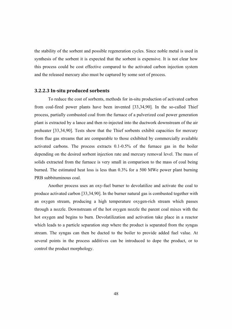
48
the stability of the sorbent and possible regeneration cycles. Since noble metal is used in
synthesis of the sorbent it is expected that the sorbent is expensive. It is not clear how
this process could be cost effective compared to the activated carbon injection system
and the released mercury also must be captured by some sort of process.
3.2.2.3 Insitu produced sorbents
To reduce the cost of sorbents, methods for in-situ production of activated carbon
from coal-fired power plants have been invented [33,34,90]. In the so-called Thief
process, partially combusted coal from the furnace of a pulverized coal power generation
plant is extracted by a lance and then re-injected into the ductwork downstream of the air
preheater [33,34,90]. Tests show that the Thief sorbents exhibit capacities for mercury
from flue gas streams that are comparable to those exhibited by commercially available
activated carbons. The process extracts 0.1-0.5% of the furnace gas in the boiler
depending on the desired sorbent injection rate and mercury removal level. The mass of
solids extracted from the furnace is very small in comparison to the mass of coal being
burned. The estimated heat loss is less than 0.3% for a 500 MWe power plant burning
PRB subbituminous coal.
Another process uses an oxy-fuel burner to devolatilize and activate the coal to
produce activated carbon [33,34,90]. In the burner natural gas is combusted together with
an oxygen stream, producing a high temperature oxygen-rich stream which passes
through a nozzle. Downstream of the hot oxygen nozzle the parent coal mixes with the
hot oxygen and begins to burn. Devolatilization and activation take place in a reactor
which leads to a particle separation step where the product is separated from the syngas
stream. The syngas can then be ducted to the boiler to provide added fuel value. At
several points in the process additives can be introduced to dope the product, or to
control the product morphology.

49
3.3.3 Sorbent injection in power plants
Many activated carbons have been tested in U.S. power plants. Table 3.2 presents
the tested sorbents and applied APCDs and coals. The mercury removal efficiencies are
not included in the table due to various mercury removal efficiencies obtained at
complicated test conditions. Instead the mercury removal efficiencies as a function of
sorbent injection rate are shown in figures.
The most studied sorbents are Darco FGD, Darco Hg, and Darco Hg-LH. The
Darco Hg is formerly known as Darco FGD manufactured specifically for the removal of
mercury in coal fired utility flue gas emission streams [80], while Darco Hg-LH is
bromine impregnated. Although the mercury levels at the inlet of ACPDs are generally
similar, the extents of mercury removal by the existing APCDs without sorbent injection
are quite different. This is due to fact that different ranks of coal and APCD
configurations are applied by different power plants.
Without looking at the detailed data of the specific plants, it is difficult to
evaluate the sorbent performance by comparing the mercury removal efficiency.
However, some trends can be observed by comparing the results obtained under similar
conditions. Figure 3.4 compares the mercury removal at Holcomb and Stanton power
station by injection of Darco Hg-LH upstream of SDA and baghouse. At Holcomb and
Stanton power station the byproduct from SDA is disposed and therefore activated
carbon is injected before the SDA and baghouse. Figure 3.5 illustrates the mercury
removal by Darco FGD injection upstream of a new added so-called COHPAC compact
hybrid particle collector. COHPAC is an EPRI-patented design that places a high air-to-
cloth ratio fabric filter downstream of an existing ESP to improve overall particulate
collection efficiency. The results of mercury removal by Darco Hg injection upstream of
cold-side ESP are presented in figure 3.6. Up to 80 mg/m3 activated carbon is applied for
systems with FF, while up to 320 mg/m3 carbon is injected upstream of cold-side ESP.
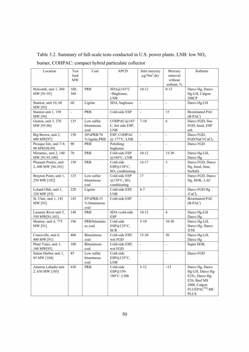
50
Table 3.2. Summary of full-scale tests conducted in U.S. power plants. LNB: low NOx
burner, COHPAC: compact hybrid particulate collector
Location Test load MW
Coal APCD Inlet mercury g/Nm3,dry
Mercury removal without
sorbent, %
Sorbents
Holcomb, unit 1, 360 MW [91-93]
180, 360
PRB SDA@143C +Baghouse, LNB
10-12 0-13 Darco Hg, Darco Hg-LH, Calgon 208CP
Stanton, unit 10, 60 MW [93]
60 Lignite SDA, baghouse - - Darco Hg-LH
Stanton unit 1, 150 MW [94]
- PRB Cold-side ESP - 15 Brominated PAC (B-PAC)
Gaston, unit 3, 270 MW [95,96]
135 Low sulfur bituminous coal
COHPAC@143C, hot side ESP, LNB
7-10 6 Darco FGD, fine FGD, Insul, ESP ash
Big Brown, unit 2, 600 MW[97]
150 30%PRB/70% lignite,PRB
ESP, COHPAC @ 177C, LNB
- - Darco FGD, FGD/NaCl/CaCl2
Presque Isle, unit 7-9, 90 MW[98,99]
90 PRB Polishing baghouse
- - Darco FGD
Meramec, unit 2, 140 MW [91,93,100]
70 PRB Cold-side ESP @160C, LNB
10-12 15-30 Darco Hg-LH, Darco Hg
Pleasant Prairie, unit 2, 600 MW [96,101]
150 PRB Cold-side ESP@138C, SO3 conditioning
16-17 5 Darco FGD, Darco Hg, Insul, lime, Sorbalit
Brayton Point, unit 1, 250 MW [102]
125 Low sulfur bituminous coal
Cold-side ESP @138C, SO3 conditioning
17 - Darco FGD, Darco Hg, HOK, LAC
Leland Olds, unit 1, 220 MW [93]
220 Lignite Cold-side ESP, LNB
6-7 - Darco FGD Hg /CaCl2
St. Clair, unit 1, 145 MW [93]
145 85%PRB/15% bituminous coal
Cold-side ESP - - Brominated PAC (B-PAC)
Laramie River unit 3, 550 MW[91,103]
140 PRB SDA+cold-side ESP
10-12 4 Darco Hg-LH Darco Hg
Monroe, unit 4, 775 MW [91]
196 PRB/bituminous coal
Cold-side ESP@125C, SCR
5-10 10-30 Darco Hg-LH, Darco Hg, Darco XTR
Conesville, unit 6, 400 MW [91]
400 Bituminous coal
Cold-side ESP, wet FGD
15-30 50 Darco Hg-LH, Darco Hg
Plant Yates, unit 1, 100 MW[93]
100 Bituminous coal
Cold-side ESP, wet FGD
- - Super HOK
Salem Harbor unit 1, 85 MW [104]
85 Low sulfur bituminous coal
Cold-side ESP@125C, LNB
- - Darco FGD
Ameren Labadie unit 2, 630 MW [105]
630 PRB Cold-side ESP@150-180C. LNB
5-12 <15 Darco Hg, Darco Hg-LH, Darco Hg-E25c, Darco Hg-E26, Basf MS 2000, Calgon FLUEPACTM-MC PLUS

51
As shown in figure 3.4 and 3.5, mercury can be efficiently removed by activated
carbon injection upstream of SDA/baghouse or a polishing baghouse. When 32 mg/m3
Darco Hg-LH in SDA/baghouse system and Darco Hg in polishing baghouse system are
applied, about 80% of mercury can be removed. Further increase of the carbon injection
rate above 32 mg/m3 results in a slow increase of the mercury removal efficiency. The
mercury removal efficiency in SDA/baghouse system by Darco Hg-LH is larger than that
by Darco Hg. This is due to the applied Darco Hg-LH sorbent, which is bromine
impregnated and has larger mercury adsorption capacity than Darco FGD. The waste
disposal cost of sorbent injection upstream of SDA/baghouse is expected to be higher
since used activated carbon cannot be separated from the desulphurization product and
regenerated. Tests at Gaston power station showed that carbon injection significantly
increased the cleaning frequency of the COHPAC baghouse [95,96]. At an injection
concentration of 32 mg/m3 the cleaning frequency increased from 0.5 to 2
pulses/bag/hour, most likely due to the small particle size of the PAC causes a high
pressure drop.
0 20 40 60 80 100
PAC injection rate, mg/m3
0
10
20
30
40
50
60
70
80
90
100
Mer
cury
rem
ova
l eff
icie
ncy
, %
Stanton, lignite, Darco Hg-LHHolcomb, PRB, Darco Hg-LHHolcomb, PRB, Darco Hg
Figure 3.4. Mercury removal as a function of injection rate of Darco Hg-LH sorbent in
power plants using SDA and baghouse as APCDs. Data are from [91-93].

52
0 20 40 60 80
PAC injection rate, mg/m3
0
10
20
30
40
50
60
70
80
90
100
Mer
cury
rem
ova
l eff
icie
ncy
, %
Gaston, bituminousBig Brown, 30%PRB/70%lignitePresque Isle, PRB
Figure 3.5. Mercury removal as a function of injection rate of Darco FGD sorbent in
power plants by sorbent injection upstream of a polishing baghouse. Data are from [95-
99].
As shown in figure 3.6, much more than 32 mg/m3 Darco Hg activated carbon are
required to obtain 80% mercury removal by carbon injection upstream of cold-side ESP,
where the flue gas temperature is about 125-160C. This is due to the short contact time
between mercury vapor and injected carbon in the ESP and mercury is mainly captured
during the carbon particle in-flight period. When bromine treated carbons B-PAC and
Darco Hg-LH is used, the mercury removal efficiency across the cold side ESP increases
significantly.

53
0 50 100 150 200 250 300 350
PAC injection rate, mg/m3
0
10
20
30
40
50
60
70
80
90
100
Mer
cury
rem
ova
l eff
icie
ncy
, %
Pleasant, PRB,Darco Hg
Brayton, bituminous,Darco HgMeramec, PRB,Darco Hg
Leland Olds, lignite,Darco Hg
Monroe,PRB,SCR bypass, Darco Hg
Stanton unit 1, PRB, B-PAC
Meramec, PRB, Darco Hg-LH
Figure 3.6. Mercury removal as a function of injection rate of Darco Hg sorbent in power
plant by sorbent injection upstream of a cold side ESP. Data are from [91,93,96,100,101].
Tests at Pleasant Prairie showed that there was no significant effect on mercury
removal with PAC injection when SO3 was used as flue gas conditioning agent to obtain
optimal dust resistivity and improve ESP performance [96,101]. The level of applied SO3
at Pleasant Prairie was not reported. However, tests at Labadie unit 2 showed that the
presence of SO3 in the flue gas can decrease mercury capture by activated carbon [105].
The applied SO3 concentration in the flue gas at Labadie unit 2 was about 5-10 ppmv.
This is probably due to the competitive adsorption between Hg and SO3 since both
mercury and SO3 bind to the Lewis acid base sites on the activated carbon surface
[21,22].
In some plants burning PRB coals, it was observed that when the carbon injection
rate was increased above 160 mg/m3 the mercury removal efficiency by the cold side
ESP leveled off at about 60% [91,93,96,100,101]. At Brayton Point plant bituminous
coal was fired and the mercury removal increased with carbon injection rates in all the
tested ranges up to 320 mg/m3 reaching 90% mercury removal [102]. This is probably
due to the fact that at the Brayton Point the predominant species of mercury is in the

54
oxidized form since there is a significant amount of HCl present in the flue gas from
Brayton [102], in contrast to Pleasant Prairie where the majority of vapor phase mercury
was in the elemental form.
3.3.4 Sorbent injection tests at cement plant
There are very limited studies on mercury removal by sorbent injection in cement
plants. In 2007 a six-week test was conducted at Ash Grove Cement Company’s Durkee
plant using a slipstream fabric filter after the main bag filter [106,107].
The overall goal of the tests at Durkee was to perform a parametric test on a
slipstream of actual flue gas to obtain an understanding of how various operating and
design parameters are likely to impact mercury control in the Durkee plant. The
evaluated parameters included activated carbon type, filter bag type, powdered activated
carbon injection rate, and filter air-to-cloth ratio.
The slipstream filter had twelve 152 mm3658 mm bags, corresponding to a
filtration area of 21 m2. The filter chamber and inlet duct were insulated and heated to
maintain a temperature of about 138°C. Mercury concentrations at the filter inlet and
outlet were measured by a Horiba/Nippon Instruments Corporation DM-6B, as well as
the Ontario hydro method. The tested carbons include Darco Hg, Darco Hg e-11, Darco
Hg LH, and Envergex e-sorb e11. The last two carbons are chemically treated. The
Darco Hg is prepared from lignite coal and the Darco Hg e-11 is a coarser version of the
Darco Hg. The particle size of the Darco Hg e-11 carbon is not reported. The test
duration for each parametric study was only about one hour. The flue gas compositions
are not publically reported and baghouse cleaning cycle is unknown.
Figure 3.7 shows the mercury removal efficiency as a function of PAC injection
rate for different carbons. For the Darco Hg and Darco Hg e-11, the mercury removal
efficiency increases only slightly from 80-90% to 90-95% when the PAC injection rate is
further increased above 48 mg/m3. The mercury removal efficiencies by the untreated
carbons are generally larger than those by the treated carbons when low injection rates
are applied. Treated carbons (Darco Hg LH and Envergex) have been shown to perform
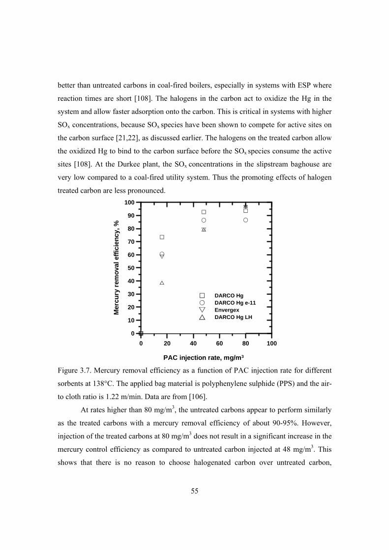
55
better than untreated carbons in coal-fired boilers, especially in systems with ESP where
reaction times are short [108]. The halogens in the carbon act to oxidize the Hg in the
system and allow faster adsorption onto the carbon. This is critical in systems with higher
SOx concentrations, because SOx species have been shown to compete for active sites on
the carbon surface [21,22], as discussed earlier. The halogens on the treated carbon allow
the oxidized Hg to bind to the carbon surface before the SOx species consume the active
sites [108]. At the Durkee plant, the SOx concentrations in the slipstream baghouse are
very low compared to a coal-fired utility system. Thus the promoting effects of halogen
treated carbon are less pronounced.
0 20 40 60 80 100
PAC injection rate, mg/m3
0
10
20
30
40
50
60
70
80
90
100
Mer
cury
rem
ova
l eff
icie
ncy
, %
DARCO HgDARCO Hg e-11EnvergexDARCO Hg LH
Figure 3.7. Mercury removal efficiency as a function of PAC injection rate for different
sorbents at 138°C. The applied bag material is polyphenylene sulphide (PPS) and the air-
to cloth ratio is 1.22 m/min. Data are from [106].
At rates higher than 80 mg/m3, the untreated carbons appear to perform similarly
as the treated carbons with a mercury removal efficiency of about 90-95%. However,
injection of the treated carbons at 80 mg/m3 does not result in a significant increase in the
mercury control efficiency as compared to untreated carbon injected at 48 mg/m3. This
shows that there is no reason to choose halogenated carbon over untreated carbon,
56
particularly in light of the higher price and potential concerns associated with the use and
disposal of halogen-treated materials.
The trend of mercury removal efficiency of Darco Hg e-11 is similar to that of
finer Darco Hg, but the Hg removal results were lower by 10%–15%. This was most
likely caused by the larger particle sizes leading to more severe diffusion limitation.
Three bag types were tested, namely, polyphenylene sulphide (PPS), membrane
and fiberglass with membrane, while other conditions of the baghouse are the same. The
primary aim of testing different bag types is to investigate whether retention of carbon
particles on the bag surface can enhance the mercury removal efficiency. The
comparison of the performance of the tree bag types is presented in figure 3.8. At PAC
injection rate above 48 mg/m3 of Darco Hg all three bag types perform quite similarly at
138°C. Considering the uncertainty caused by the variability between the inlet and the
outlet mercury measurements, it is likely that the bags are performing essentially the
same at these conditions [108]. Then the only controlling factor for choosing the bag
type is the working temperature. The flue gas temperature in the bag filter area of the
cement process varies a lot and can exceed 200°C. Among the tested bag types, only the
membrane/fiberglass bag can withstand continuous operating temperatures at 260°C and
is therefore recommended.

57
0 20 40 60 80 100
PAC injection rate, mg/m3
0
10
20
30
40
50
60
70
80
90
100
Mer
cury
rem
ova
l eff
icie
ncy
, %
PPSmembrane/fiberglassMembrane
Figure 3.8. Effects of bag material on mercury removal efficiency at 138°C. The applied
air-to-cloth ratio is 1.22 m/min and the sorbent is Darco Hg. Data are from [106].
The effect of air-to-cloth ratio on mercury removal was tested using the
membrane/fiberglass bag. It is reported that at a PAC injection rate of 16 mg/m3 the
mercury removal efficiency increased with increasing the air-to-cloth ratio in the range of
1.2-3.0 m/min and when the injection rates were higher than 48 mg/m3 the mercury
removal efficiency increases only slightly with further increasing the injection rate since
the mercury removal efficiency is higher than 90% [106]. The increase of mercury
removal efficiency with filtration velocity might be due to the fast accumulation of
carbon on the bag surface. However, care must be taken when discussing the observation.
The cleaning control of the bags was not specified. It is unknown whether the bags were
cleaned at a fixed time interval or defined pressure drop over the filter. Most of the tests
were conducted for a period of only about 20 min, while only several tests were run for
up to 1-2 h.
Injection of Darco Hg before the fabric filter with membrane/fiberglass was also
tested in the raw-mill-off operating period. The mercury concentration at the filter inlet
during the raw-mill-on period was about 485 µg/Nm3, but increased to about 2600

58
µg/Nm3 during raw-mill-off operating period. Using an air-to-cloth ratio of 2.4 m/min,
moderate mercury removal efficiencies of 52% and 58% were obtained at PAC injection
rates of 48-80 mg/m3, respectively. A mercury removal efficiency of 88% was achieved
when the PAC injection rate was increased to 160 mg/m3.
Based on the parametric study at 138C, design parameters for the full-scale
sorbent injection upstream of a polishing filter at Durkee cement plant were
recommended. The untreated carbon, fiberglass with membrane bag type, and air-to-
cloth ratio of 1.8-2.4 m/min were suggested. The proposed sorbent injection rate is 48
mg/m3 and 80 mg/m3 for the raw-mill-on and raw-mill-off operation period, respectively.
The estimated mercury removal efficiency is 90% during raw-mill-on conditions and
60% during raw-mill-off conditions. The weighted mercury removal efficiency expected
is about 77% on annual average.
3.3.5 Carbon surface chemistry and mechanisms of mercury capture on
carbons
3.3.5.1 Carbon surface chemistry
The surface chemistry of carbons determines their moisture content, catalytic
properties, acid-base character, and adsorption of polar species. It is related to the
presence of heteroatoms other than carbon within the carbon matrix. The most common
heteroatoms are oxygen, nitrogen, phosphor, hydrogen, chlorine, and sulphur [109].
During preparation of carbon and particularly during cooling and storage, carbon
materials are in contact with the ambient air so that elements such as H and O are fixed
on the surface, leading to oxygenated chemical functional groups [110]. Several
structures of oxygen functional groups have been proposed as shown in table 3.3.
Functional groups can be acidic, basic, or neutral in character. Surface oxygen groups on
carbon materials decompose upon heating by releasing CO and CO2 at different
temperatures. A CO2 peak results from carboxylic acids at low temperatures, or lactones
at higher temperatures; carboxylic anhydrides originate both a CO and a CO2 peak;
phenols, ethers, carbonyls, and quinones originate a CO peak.

59
Table 8. Surface oxygen groups on carbon and their decomposition by TPD, after
[110,111].
Group name Decomposition product
Decomposition temperature (C)
Carboxyl CO2 100-400
Lactone CO2 190-650 Carboxylic anhydrides CO+CO2 350-627 Phenolic CO 600-700 Ether CO 700 Carbonyl CO 700-980 Quinone CO 700-980
Besides oxygenated functions, nitrogenated functions can be introduced on
carbon surface by reaction of a carbon with a nitrogen-containing reactant or preparation
of a carbon from a nitrogen-containing precursor [110].
3.3.5.2 Mechanisms of mercury capture on carbons
In order to understand the mercury capture mechanisms, it is important to
understand the chemical and physical nature of the mercury-sorbent interaction. X-ray
absorption fine structure (XAFS) spectroscopy and X-ray photoelectron spectroscopy
(XPS) are techniques that have been previously used to determine information about the
speciation and binding of mercury on a variety of materials [112,113]. XAFS spectra can
be defined by two regions which include X-ray absorption near-edge spectroscopy
(XANES) and extended X-ray absorption fine structure (EXAFS) spectroscopy. XANES
spectra provide information on the oxidation state and characteristics of the first neighbor
coordination environment. EXAFS spectroscopy provides more robust information on
the identity of nearest-neighboring elements, coordination values, and interatomic bond
distances.
XAFS spectroscopy was used to distinguish between elemental and oxidized
mercury in the sorbents by comparing the XAFS spectrum. Elemental mercury exhibits a

60
single peak only in the first-derivative of the mercury XANES spectrum, whereas most
mercuric compounds exhibit a two-peak spectrum [112]. The sorbents were tested for
mercury capture at temperatures lower than 200°C. The studied sorbents included
carbonaceous materials and inorganic-based material, such as lime-derived sorbents and
zeolites.
The XANES data imply that the capture of elemental mercury must involve an
oxidation process, either in the gas phase before interacting with the sorbent, or
simultaneously as the Hg0 atom interacts with the sorbent [112]. This is consistent with
the fact that all Hg-sorbed materials examined exhibit the characteristic dual inflection
point structure in their XANES spectra that is indicative of the formation of Hg–anion
chemical bonds. The anion could be virtually any available electronegative species, as
evidence has been seen for the formation of Hg–I, Hg–Cl, Hg–S, Hg–O, and Hg-Br
[112,113]. Modeling of mercury capture by activated carbon using density functional
theory shows that the mercury binding energies increase with the addition of the
following halogen atoms, F>Cl>Br>I [114]. Data from S and Cl XANES spectra, as well
as from the Hg XAFS data, strongly support the hypothesis that interaction of acidic
species (HCl, HNO3, H2SO4, HBr, etc.) in the flue gas with the sorbent surface is an
important mechanistic process that is responsible for creation of active sites for mercury
capture by chemisorption. The mechanisms of elemental mercury capture on the carbon
sorbents likely consist of surface-enhanced oxidation of the elemental mercury via
interaction with surface-bound halide species with subsequent binding by surface halide
or sulphate species [113].
The catalytic effects of carbon sorbents for mercury capture were investigated by
Olson et al. [115]. The studied carbons were lignite- and bituminous-derived carbon and
catalytic carbon, which were available commercially with enhanced catalytic
functionality for aqueous reactions such as decomposition of peroxides. Catalytic
carbons are produced by recarbonization of urea or ammonia-treated oxidized activated
carbons or by impregnation of nitrogen-containing polymers and pitches [115]. Without
acid gases in the gas stream at 150C, 50% mercury breakthrough was observed after 8

61
min for the catalytic carbon, while less than 1 min for the lignite- and bituminous-derived
carbons. Thus, a catalytic chemisorption mechanism predominates for the sorption of
mercury at these conditions.
The mercury adsorption capacity of the sorbent is inversely proportional to the
temperatures in a studied range of 50-150°C, indicating that a preliminary physisorption
step with mercury associating with a surface site takes place [115]. The chemisorption of
Hg0 is likely a multistep reaction. When the temperature is increased, the rate of each
chemical reaction step increases and the exothermic physisorption of Hg0 at non-
oxidizing binding sites will decrease. If the sorption process includes a preliminary
physisorption equilibration where Hg0 binds and desorbs at the active site, the
equilibration will show a negative temperature effect on the overall reaction rate, since
desorption is favored at higher temperatures. Although chemisorption may account for
the main sorption of mercury, the extent to which increasing the temperature may affect
the sorption rate cannot be predicted.
A detailed mechanism has been proposed to explain the effects of SO2 and NO2
as shown in figure 3.9 [116]. In the presence of NO2, Hg0 is catalytically oxidized on the
carbon surface to form the nonvolatile nitrate Hg(NO3)2, which is bound to basic sites on
the carbon. The Lewis base site refers to the zigzag carbon atom positioned between
aromatic rings [117]. Capture continues until the binding sites are used up and
breakthrough occurs. In the presence of SO2, some of the catalytic sites are converted to
a sulfate form where Hg(NO3)2 is no longer formed. Mercury is still oxidized on the
surface with NO2 acting as the oxidizing agent, but the product formed is a labile sulfur
compound, mercury bisulfate [Hg(SO4H)2]. The bisulfate in turn reacts with NO3- to
form a stable but volatile acidic form of the mercuric nitrate. The emission of Hg(NO3)2
or the hydrate Hg(NO3)2H2O has been confirmed by solvent trapping and gas
chromatography analysis. Sulfurous acid that accumulates from the hydration of SO2
converts the previously formed nonvolatile basic mercuric nitrate into the volatile form,
which explains the slow release of previously captured mercury over time in the presence
of NO2 and SO2.

62
Figure 3.9. Proposed heterogeneous model for mercury capture on carbon showing
potential impact of acid gases [116].
Sulphur trioxide can be present in power plant flue gas through one of the
following paths [21]: (1) During combustion, coal-S is converted to SO2 and a small
fraction of the sulfur is further oxidized to SO3. During combustion of high-sulfur coals,
a minor part of the sulfur is converted to SO3, leading to flue gas concentrations in the
range of 1-40 ppm. (2) SO3 is sometimes added to a level above 10 ppm to flue gas
upstream of an ESP as a conditioning agent and to improve ESP performance. SO3 and
H2SO4 have a low vapor pressure and can condense on fly ash and this reduces the
resistivity of the ash and allows it to be removed more efficiently by the ESP. (3) SO2
can be oxidized to SO3 by SCR catalysts installed for NOx reduction [118-120]. SCR
catalysts typically contain vanadium oxides, which are known catalysts for the oxidation
of SO2 to SO3 and Hg to HgCl2.
The inhibiting effect of SO3 on mercury capture by activated carbon injection has
been observed in full-scale power plant tests [21,121]. Possible mechanisms for the SO3
effect on mercury capture by activated carbon are postulated by Presto and Granite
[21,22]. In addition to removing mercury, activated carbon is also used as catalyst for
oxidation of SO2 to sulphuric acid [122,123]and as SO2 sorbent. There is competitive
adsorption between Hg and SO3 since both mercury and SO3 bind to the Lewis acid base

63
sites on the activated carbon surface. The adsorption of SO3 could be favored both
kinetically and thermodynamically. The concentration of SO3 in flue gas is typically in
the range of 1-40 ppm and this is orders of magnitude larger than typical mercury
concentrations. The bond formed between the S6+ species, such as sulfuric acid and
sulfates, and the carbon surface is stronger than the bond between mercury and the
surface. SO2 can oxidize to sulphate and form a chemical bond with the carbon surface
with a heat of adsorption of >80 kJ/mol. Some activated carbon catalysts for converting
SO2 to H2SO4 are self-poisoned by SO3 or sulfate buildup on the surface. A similar
phenomenon might explain the inhibiting effect of SO3 on mercury capture.
3.3.6 Processing and reuse of mercury laden activated carbon
The existing production capacity for powdered activated carbon is only 10% of
the capacity required for full implementation of the activated carbon injection technology
to control mercury emissions [124]. The mercury sorption capacity of the activated
carbon is very low, about 1-4 mg of mercury per gram of sorbent, depending on the
mercury concentration in the flue gas [125]. This implies that 250 to 1000 g of activated
carbon are needed to remove 1 g of mercury in the flue gas. Therefore, a large quantity of
spent sorbents contaminated with various forms of mercury is produced.
Presently the PAC with adsorbed mercury must be disposed after use. In addition
to the purchase expense, the disposal of this material is also quite costly. There are strict
regulations for disposal of mercury-containing wastes [126]. Hazardous wastes
containing less than 260 mg/kg of total mercury are required to be treated to 0.20 mg/L,
measured using the toxicity characteristic leaching procedure (TCLP) for mercury
residues from retorting, and 0.025 mg/L TCLP for all other low mercury wastes. Wastes
that contain greater than 260 mg/kg total mercury are required to undergo roasting or
retorting in a thermal processing unit capable of volatilizing mercury and subsequently
condensing the volatilized mercury for recovery.
To reduce the PAC purchase expense and disposal cost of mercury-containing
PAC, a process has been developed to regenerate the used PAC and recover mercury
[124]. To separate PAC from the fly ash, PAC is injected between the main filter and the

64
polishing FF. The collected PAC is periodically removed from the filter and regenerated
in nitrogen process gas and is directed to a multiple activated carbon column gas
treatment system to remove the gaseous mercury from the cooled process gas stream.
After passing through the sulphur impregnated carbon columns, the carrier gas is injected
into the flue gas stream ahead of the carbon injection site. In this way only a small
amount of carbon with high mercury content requires disposal.
An inert atmosphere is required for the tray desorption furnace to avoid
significant losses of the PAC material during mercury desorption. Using a desorption
temperature of 550°C and a duration of 30 minutes, the PAC can be recycled at least 10
times without significant degradation of the adsorption characteristics in nitrogen [124].
It is unknown whether the cycled sorbent works satisfactorily in the real flue gas.
There are only few studies on the mercury desorption from exposed sorbents. It is
worth noting that mercury desorption is relevant both to recover the mercury and to
detoxify the adsorbing material in order to avoid its stabilization before land-filling or to
allow its reuse.
A study of mercury desorption in nitrogen from sulphur impregnated activated
carbon showed that the adsorption rate was faster than the desorption rate [59]. Mercury
desorption from sorbents is strongly affected by desorption temperature, with faster
desorption at high temperature and the mercury-sorbent pair. The desorption rate is
relatively fast initially and then levels off close to zero at a certain concentration of
mercury in sorbents.
Desorption of mercury from activated carbon and fly ash mixture was also carried
out in a fluidized bed reactor at temperatures up to 500°C [127]. All the mixtures had
constant mercury content, i.e., no mercury desorption was observed, until a critical
temperature was reached and then with rapidly decreasing mercury content as the
temperature was increased to higher levels. The critical temperature was found to be a
linear function of carbon contents in the mixtures, increasing from 330°C at 17% carbon
to 370°C at 33% carbon. The temperature at which all of the mercury was removed was
in the 450 to 500°C range.

65
3.3.7 Applicability of sorbent injection in cement plants
As PAC systems are adapted for control of boilers, it will be possible to evaluate
the feasibility of these control techniques for cement kiln applications having
approximately the same mercury concentrations. Considering the differences between
boiler and kiln applications the possible application of PAC systems to cement kilns
appears to be considerably more challenging than to coal-fired boilers.
Powdered activated carbon injection systems do not appear to be appropriate
upstream of a cement kiln fabric filter system. Cement kilns must recycle a major portion
of the collected dust. Some kilns use the fabric filter system as an integral part of the raw
material processing system. Recycling the mercury laden activated carbon would result
in the revolatilization of the large majority of the mercury. Disposal of the activated
carbon containing cement kiln dust (CKD) also would be complicated because it might
be classified as a hazardous waste due to the presence of mercury.
Due to these issues, a powdered activated carbon injection system would have to
be installed downstream of the main kiln fabric filter to avoid the CKD recycling and
disposal issues. A second fabric filter would have to be installed after the main fabric
filter. The activated carbon injection system would have to be positioned to provide one
to two seconds residence time prior to entering the second fabric filter. The temperature
of this system would have to be controlled to less than 200C to ensure proper mercury
adsorption and reduce the risk of activated carbon fires in the fabric filter or solids
handling system.
3.4 Mercury removal by activated carbon bed
Fixed and moving bed systems for mercury and dioxin-furan control are also used
in Europe [5]. In both types of systems, contaminant-laden gas is forced through a bed of
granular activated carbon.
One of the fixed bed systems used Sorbalit sorbent instead of activated carbon.
The Sorbalit sorbent consists of Portland cement, lime, carbon, and sulfur compounds
such as sublimed sulfur, Na2S, NaHS, and Na2S4 [16].

66
The quantity of mercury that can be retained on the sorbent at equilibrium is
important. The sorbent can be used at levels that approach the saturation capacity of the
sorbent at the operating gas temperature and gas stream conditions. However, the control
system must have the capability to remove the sorbent on at least a semi-continuous basis.
In fixed bed systems, the activated carbon must be replaced with fresh carbon at a
rate that is dependent primarily on the rate of approach to the mercury saturation level,
and the rate of static pressure increase. Spent carbon can be disposed of by combustion if
the unit is equipped with a wet scrubbing system. The combustion process destroys the
organic compounds captured in the carbon, and the wet scrubber collects the heavy
metals and acid gases. In this case, however, the elemental mercury might not be
removed due the insolubility of elemental mercury in the water. Another disposal option
is to dispose the carbon in a landfill. Because of the adsorbed pollutants, this waste may
require disposal as a hazardous waste. Another option is to heat the carbon and desorb
the pollutants from the carbon.
Slipstream tests of the activated carbon bed have been recently conducted in
several U.S. power plants [128]. Direct adaptation of existing carbon bed technology to
mercury removal from utility power plant flue gas is very costly because of the large flue
gas volumes and low mercury concentrations involved [129]. A thorough engineering
and economic analysis would be necessary to determine the feasibility of modifications
that reduce bed size and the amount of carbon in the bed. The effectiveness of the
modified beds for mercury removal under various flue gas conditions needs to be
determined. Furthermore, the tradeoff between gas velocity to the bed, bed sorbent size
and bed thickness, pressure drop, mercury and ash collection effectiveness, and bed
lifetime should be examined.
For cement plant application, the fixed bed activated carbon systems could not be
installed upstream of the main kiln bag filter or ESP. The high dust loadings in these
locations would quickly blind both types of beds and result in very high activated carbon
usage rates and disposal requirements. Accordingly, it would be necessary to install these
systems downstream of the main particulate matter control system. Similar to the power

67
plant application, installing a fixed bed carbon system in a cement plant will also be very
costly.
3.5 Mercury control by flue gas desulphurization systems
Dry and wet scrubbers, commonly used in large scale combustion systems for
SO2 and HCl control can be simultaneously used for mercury retention, taking advantage
of the same sorbents used for sulphur or adding a new material for mercury [130-133].
Wet scrubbing systems predominately collect oxidized mercury [5,131]. In the purge
stream, mercuric chloride is collected as a precipitated solid along with the calcium
sulfate. When used as stand alone systems, they have the capability to achieve moderate-
to-high removal efficiencies for oxidized mercury. They are entirely ineffective in the
removal of the highly insoluble elemental mercury.
There are limited number of lime-based scrubbing systems used primarily for
particulate and SO2 control at lime kilns. There are presently only few cement kilns in the
United States equipped with wet SO2 scrubbing systems [5].
The stability of oxidized mercury captured in the flue gas desulphurization (FGD)
systems has been investigated and it was found that the captured oxidized mercury can be
reduced by aqueous phase reactions to form elemental mercury [6]. The insoluble
elemental mercury is rapidly released to the gas stream. Occurrence of mercury in FGD-
gypsum may threaten its re-use for wallboards since mercury can be released during the
heating steps in wallboard manufacturing [131].
Spray dryer absorbers (SDA) with a Ca(OH)2 slurry have been used for sulfur
dioxide and hydrogen chloride control at waste incinerators and coal-fired boilers. SDA
has been applied recently to cement kilns to control HCl that contributes to secondary
plume formation [5].
SDA systems would have to be installed after the main particulate matter control
system to ensure that captured mercury remains with a solid waste product and is not
recycled to the feed end of the kiln. With respect to fossil fuel fired boilers, the reported
mercury removal efficiencies by SDA systems are in the range of 50% to 60% for eastern

68
bituminous coals and 0% to 20% for western lignite and subbituminous coals [5]. The
difference is caused by the lower fraction of oxidized mercury for the lignite coals. With
respect to cement kilns, it appears unlikely that SDA systems will be more effective than
inherent adsorption in cement kiln systems.
3.6 Mercury removal by sodium tetrasulfide injection
Sodium tetrasulfide (Na2S4) has been used as a sorbent to remove mercury from
flue gas in a number of waste-to-energy plants [1]. This technology should not be
confused with sodium sulfide Na2S that was tried in both Europe and U.S. without
success [134]. The shortcomings of Na2S are that it can leave a strong odor of hydrogen
sulfide (H2S) in the ash and it does not control all species of Hg. The major advantages of
the Na2S4 technology are that it controls elemental as well as ionic forms of Hg.
An aqueous Na2S4 solution is injected into the flue gas duct and such a system
can easily be retrofitted to an existing flue gas cleaning plant [134]. The sodium
tetrasulfide reacts with vapor phase mercury to form solid mercuric sulfide (HgS), which
is a solid at temperatures below about 580°C, and is insoluble [134]. By converting
vapor-phase mercury to an insoluble solid, it may be removed in a FF or ESP. Sodium
tetrasulfide can react with both oxidized and elemental mercury in accordance with the
following simplified reactions [134]:
2 4 2 2 3Na S HgCl HgS NaCl S (R3.4)
Hg S HgS (R3.5)
Decomposition of Na2S4 by an acid such as HCl can provide excess elemental
sulfur. It can also generate an alternate form of ionic sulfur, H2S, for reaction with
oxidized mercury as shown in the following reactions:
2 4 22 3 2Na S HCl H S S NaCl (R3.6)
2 2 2HgCl H S HgS HCl (R3.7)
In the absence of HCl, carbon dioxide may act as an acid for decomposition:
2 4 2 2 2 32 2 3 2Na S CO H O H S S NaHCO (R3.8)

69
Therefore, it is possible to eliminate both the elemental and ionic forms of mercury in the
flue gas.
However, H2S will still be produced in the process as shown in R3.6 and R3.8.
The problem of H2S odor in the ash cannot be avoided. This process is not suitable to
mercury removal from cement plant due to the presence of sodium, which could
deteriorate the cement quality.
3.7 Enhanced mercury removal by oxidation
Oxidation pretreatment systems may convert elemental mercury to oxidized
mercury upstream of wet scrubber systems and even upstream of conventional particulate
matter control systems. Once in the oxidized form, mercury is captured in these air
pollution control systems at efficiencies approaching 85% [5]. The oxidation
pretreatment systems must be able to withstand the gas stream conditions upstream of the
air pollution control system used for capture of the oxidized mercury. Oxidation
pretreatment systems are only effective for the vapor phase mercury that is not adsorbed
on particle surfaces.
Selective non-catalytic reduction (SNCR) and selective catalytic reduction (SCR)
systems are used in coal-fired boilers and waste incinerators for the control of nitrogen
oxides. The impact of SNCR systems on the chemical form of mercury in a gas stream
appears to be minimal [5].
SCR systems use a catalyst to react ammonia and nitrogen oxides to provide
nitrogen and water. SCR systems are used extensively for coal-fired boilers and waste
incinerators. Full-scale tests have been performed in four U.S. power plants and the
results are presented in table 3.4 [135,136]. Significant oxidation of elemental mercury
across the SCR was observed in plant 2 and 4. While slight mercury oxidation over SCR
was experienced in pant 1 and 3. General conclusions from these tests are the oxidation
effect was quite variable and appears to be coal-specific and possibly catalyst-specific. In
particular, the catalyst type, space velocity, and catalyst age may all be important
variables. Plant 1 burns PRB coal with lower chlorine content and the catalyst is older.

70
More than 90% of the mercury in the flue gas at plant 1 is elemental mercury at the SCR
inlet. One possible explanation for the relatively low oxidation rate of the SCR at plant 3
is the relatively high space velocity, which is nearly double the space velocity compared
to other plants. In addition, the total inlet mercury concentration was more than twice the
levels seen at the other test sites.
Table 3.4. Test conditions and results of mercury oxidation over SCR catalyst in four U.S.
power plants. Data are from [135,136].
Plant 1 2 3 4 Coal PRB
subbituminous
Ohio bituminous high-sulfur
Pennsylvania bituminous low-to-medium sulfur
Kentucky bituminous medium-sulfur
Hg in coal (ppmm) 87 168 400 131 Cl in coal (ppmm) <60 573-1910 721-1420 357-1160 Catalyst vendor Cormetech Siemens KWH Cormetech Catalyst type Honeycomb Plate Honeycomb Honeycomb Catalyst age (h) 8000 2500 3600 3600 SCR space velocity (h-1)
1800 2125 3930 2275
Oxidized Hg increase over SCR (%)
From 8 to 18 From 48 to 91
From 55 to 65 From 9 to 80
Tests were also carried out at two Danish power plants equipped with Topsøe
DNX SCR catalysts and firing bituminous coal with different Cl-levels (0.01 to 0.13%)
[137]. The tests show a high degree of Hg0 oxidation over the SCR catalyst, ranging from
53 to more than 90% depending on operating conditions (load, coal type) and the
sampling method. Furthermore, it is shown that high coal chlorine results in higher Hg0
conversion over the SCR reactor than low chlorine coal.
The effects of different gases on mercury oxidation over SCR catalysts have been
studied [138-143]. Hydrogen halogens (HF, HCl, HBr, and HI) promote mercury
oxidation over the SCR catalyst [141]. It is HCl and not Cl2 that is the major source of
chlorine that dominates the Hg0 oxidation process within the typical SCR temperature

71
range (300-350°C) in a real flue-gas atmosphere [139], while NH3 shows a small
detrimental effect. Adding 2000 ppmv SO2 to baseline gases that contain 6% O2, 12%
CO2, 8% H2O, 550 ppmv NH3, 600 ppmv NO, 18.5 ppmv NO2 without HCl only
increases the mercury oxidation over SCR from 3% using baseline gases to 7% with
2000 ppmv SO2 [139,142].
Adding 50 ppmv SO3 to the baseline gases improves the mercury oxidation to
20% [139,142]. Adding 50 ppmv HCl to the baseline gases without SO2/SO3 results in
71% oxidized mercury in flue gas across the SCR compared to 45% mercury oxidation
when 50 ppmv SO3 was further added to the flue gas. With 50 ppmv HCl and 2000 ppmv
SO2 were added to the baseline gases, mercury oxidation recovered to 64%. The
combination of 2000 ppmv SO2/50 ppmv SO3 and 50 ppmv HCl showed a 63% mercury
oxidation. These observations indicate that both SO2 and SO3 had a negative effect on
mercury–chlorine oxidation over the SCR as a result of slower mercury oxidation by the
sulfated site compared to that of the chlorinated site. The extent of the mitigating effect
by the 2000 ppmv SO2 was not as severe as the 50 ppmv SO3 since the concentration of
SO3 derived through SO2 oxidation over SCR was much lower than the 50 ppmv SO3.
There is possible competition between HCl, SO2, and SO3 over the SCR catalyst.
Conventional SCR catalyst with higher mercury oxidation capacity has been
closely related to higher oxidation of SO2 to SO3 [144]. Higher SO2 oxidation in coal-
fired applications can cause negative downstream impacts such as air heater fouling, flue
duct corrosion and visible stack plumes. The SO2 to SO3
conversion is designed to be less
than 1.5% at SCR operating conditions. Research has been focused on developing new
SCR catalyst that has higher oxidation rate of elemental mercury and very low SO2 to
SO3 conversion [144].
Two studies have demonstrated that ultraviolet radiation in the presence of solid
titanium dioxide (TiO2) results in the photocatalytic conversion of elemental mercury to
HgO when HCl is not present in the gas [6,145,146]. The TiO2 is readily available as a
major component of conventional SCR catalysts. Accordingly, the combination of
ultraviolet light and SCR catalysts could in principle be used to oxidize elemental

72
mercury. Compared to lab-scale study where ultraviolet light can be readily applied,
application of ultraviolet light in monolith catalyst could be a technical challenge.
The application of SCR systems to cement kilns continues to be precluded by
problems associated with alkali metal and arsenic related catalyst poisoning, SO2
oxidation to SO3, particulate matter loadings that can be 5 to 20 times higher than coal-
fired boiler high dust systems, and non-ideal temperature ranges for SCR catalysts
[147,148]. For these reasons, it is unlikely that an SCR system will be used for the
control of nitrogen oxides and oxidation of elemental mercury in cement plants in the
near future.
3.8 Mercury removal by roaster process
Recently a new process for mercury removal from the cement kiln flue gas by a
roaster was invented and patented [149-151]. As mentioned earlier recycled cement kiln
dust from the main bag filter has high mercury content. The mercury flow in the
collected cement kiln dust is about 60% of the mercury inlet to the cement kiln [152].
This indicates that dust captured in the main baghouse acts as a natural sorbent for
mercury. This mercury enriched dust is taken to the new mercury roaster process for
cleaning before the dust is returned to the system. Figure 3.10 illustrates an example of a
mercury roaster installation. The baghouse dust is fed to a roasting system which uses a
heat source (for example kiln bypass gas, cooler vent gas, or hot gas generator) to heat
the dust above the boiling point of mercury compounds. While the mercury is still in the
gas phase, the gas stream enters a hot ESP which removes most of the cleaned dust. This
dust is taken back to the blending silo to be part of the kiln feed. After the ESP, the gas
stream is cooled below the mercury boiling point so that the mercury can condense on
the dust particles that were not captured in the ESP and additional sorbent is added to the
gas stream here to capture the mercury. The cleaned gas after the baghouse is vented to
the atmosphere. Depending on the type of applied sorbents the mercury enriched
dust/sorbent collected in the baghouse can be transported to the finish mill area to be

73
added to the cement or disposed as waste. The air and sorbent flow rates are expected to
be smaller than what would be seen with a full carbon injection system.
Figure 3.10. Sketch of the roaster process [149].
It should be pointed out that the process is still under development. Information is
lacking on the achievable mercury removal efficiency and operating cost. Since most
dust is removed by the ESP it appears that sorbent is still required for capture the
mercury evaporated from the roaster. Calcium chloride may be required to oxidize the
elemental mercury and enhance mercury capture by the sorbent. It is unclear how
effectively the elemental mercury can be oxidized and how much calcium chloride is
required.
3.9 Conclusions
Mercury can be removed from the flue gas by fuel cleaning and switching, raw
material cleaning, sorbent injection, sorbent bed, oxidation by catalyst and subsequent
removal by wet scrubber, spray drier absorber, and roaster process with smaller sorbent
injection system. Presently sorbent injection is considered as the most promising and
developed mercury removal technology. Mercury removal by sorbent injection can be
affected by many factors such as mercury speciation and concentration, flue gas
74
composition and temperature, mercury vapor-sorbent contacting time, sorbents and
sorbent dispersion, etc. Due to the high moisture level and lack of carbonaceous particles
in the cement kiln flue gas, and release of the captured mercury during recirculation to
the kiln, the application of sorbent injection to cement kilns will be more challenging and
the obtained knowledge from coal-fired power plants and waste incinerators cannot be
applied to cement kiln directly. The PAC injection system should be installed
downstream of the main kiln fabric filter and upstream of a new added polishing fabric
filter to avoid the cement kiln dust recycling and increased disposal issues.
Powdered activated carbon is the most widely used sorbent for mercury removal
from flue gas. However, there is a lack of fundamental investigation of mercury
adsorption by activated carbon in simulated cement kiln flue gas. Even for power plant
application, mercury capture kinetics is not available in most of the publications and
many of the studies were carried out in air or nitrogen without acid gases presence. The
majority of the publications focused on elemental mercury capture and only few studies
investigated capture of HgCl2 which is a major mercury species. To reduce the cost of
sorbent and possible disposal expense, non-carbon based and concrete/cement friendly
sorbents such as Amended SilicateTM have been developed. Other developments include
regeneration and recirculation of sorbents and in-situ generation of activated carbon. The
performance of these sorbents needs to be proved in the full-scale application.
The carbon-oxygen surface complexes and flue gas composition play an
important role in mercury removal by activated carbon injection. Both physisorption and
chemisorption are involved in mercury capture by carbons. The mechanisms of elemental
mercury capture on the carbons consist of surface-catalyzed oxidation of the elemental
mercury via interaction with surface-bound halide species with subsequent binding by
surface halide or sulphate species. Co-presence of SO2 and NO2 in the flue gas results in
a poor performance of carbons. There is competitive adsorption between Hg and SO3
since both mercury and SO3 bind to the Lewis acid base sites on the activated carbon
surface.
75
3.10 Further research requirement
Activated carbon injection is a promising technology, but further research is
needed to provide the best sorbent with effective mercury capture at a low cost.
Investigation of mercury capture by the activated carbon using simulated cement kiln
flue gas is imperative to evaluate whether the activated carbon is also a promising
sorbent for cement plant application. Lab-scale tests are desired to obtain kinetics and
study the effects of different operating parameters.
More focus is needed on developing alternative sorbents. Fly ash and cement raw
materials such as clay and silica might be used as cement-friendly sorbents and
alternatives for activated carbon. A better understanding of mercury removal by fly ash
and other cement-friendly sorbents is therefore needed. Fundamental investigation on the
regeneration of the sorbents and enhancement of the sorbents by adding chemical agents
during regeneration is required. Focus should be put on desorption temperature,
separation and purification of collected mercury compounds and possible regeneration
cycle of the sorbents. Possibility of regenerating the sorbent by hot flue gas from the kiln
system and in-situ enhancement of the sorbent should be investigated.
3.11 Abbreviations
APCD: Air pollution control device
CKD: Cement kiln dust
COHPAC: Compact hybrid particulate collector
ESP: Electrostatic precipitator
EXAFS: Extended X-ray absorption fine structure
FF: Fabric filter
FGD: Flue gas desulphurization
LNB: Low NOx burner
PAC: Powdered activated carbon
PPS: Polyphenylene sulphide
PRB: Powder River Basin

76
SCR: Selective catalytic reduction
SDA: Spray dryer absorber
SNCR: Selective non-catalytic reduction
TCLP: Toxicity characteristic leaching procedure
TDF: Tire-derived fuel
XAFS: X-ray absorption fine structure
XANES: X-ray absorption near-edge spectroscopy
XPS: X-ray photoelectron spectroscopy
3.12 References
[1] A. Licata, R. Beittel and T. Ake, Multi-pollutant emissions control & strategies: Coal-fired
power plant mercury control by injecting sodium tetrasulfide, Institutes of Clean Air Companies
(ICAC) Forum 2003, Nashville, TN, October 14-15, 2003.
[2] F. Rubiera, S.T. Hall, C.L. Shah, Sulfur removal by fine coal cleaning processes, Fuel. 76
(1997) 1187-1194.
[3] D. Akers, R. Dospoy, Role of coal cleaning in control of air toxics, Fuel Processing
Technology. 39 (1994) 73-86.
[4] R.J. Conzemius, C.D. Chriswell, G.A. Junk, The partitioning of elements during physical
cleaning of coals, Fuel Processing Technology. 19 (1988) 95-106.
[5] J. Richards, Capabilities and limitations of available control technologies for mercury
emissions from cement kilns, PCA R&D Serial No. 2748a, 2005.
[6] T.D. Brown, D.N. Smith, R.A. Hargis Jr., W.J. O'Dowd, Mercury measurement and its
control: What we know, have learned, and need to further investigate, EM: Air and Waste
Management Association's Magazine for Environmental Managers. (1999) 47-50.
[7] D.J. Akers, Coal cleaning controls HAP emissions, Power Eng. 100 (1996) 33.
[8] U.S. EPA, Mercury study report to congress, EPA-452/R-97-003, 1997.
[9] N. Yoshiyuki and T. Haruhiko, Method of producing cement, Patent, JP2007326750, 2007.
[10] T. Junichi, U. Yasuhiro and Y. Osamu, Method of treating exhaust gas from cement kiln,
Patent, JP2003192407, 2003.
[11] Y. Zhuang, S.J. Miller, Impact of supplemental firing of tire-derived fuel (TDF) on mercury
species and mercury capture with the advanced hybrid filter in a western subbituminous coal flue
gas, Energy Fuels. 20 (2006) 1039-1043.
[12] J. Richards, D. Goshaw, D. Speer and T. Holder, Air emissions data summary for Portland
cement pyroprocessing operations firing tire-derived fuels, PCA R&D Serial No. 3050, 2008.

77
[13] J.H. Pavlish, E.A. Sondreal, M.D. Mann, E.S. Olson, K.C. Galbreath, D.L. Laudal, S.A.
Benson, Status review of mercury control options for coal-fired power plants, Fuel Processing
Technology. 82 (2003) 89-165.
[14] T.C. Ho, P. Yang, T.H. Kuo, J.R. Hopper, Characteristics of mercury desorption from
sorbents at elevated temperatures, Waste Management. 18 (1998) 445-452.
[15] R. Yan, D.T. Liang, L. Tsen, Y.P. Wong, Y.K. Lee, Bench-scale experimental evaluation of
carbon performance on mercury vapour adsorption, Fuel. 83 (2004) 2401-2409.
[16] J.J. Cudahy, R.W. Helsel, Removal of products of incomplete combustion with carbon,
Waste Manage. 20 (2000) 339-345.
[17] Y.H. Li, C.W. Lee, B.K. Gullett, The effect of activated carbon surface moisture on low
temperature mercury adsorption, Carbon. 40 (2002) 65-72.
[18] W. Liu, R.D. Vidic, T.D. Brown, Impact of flue gas conditions on mercury uptake by sulfur-
impregnated activated carbon, Environ. Sci. Technol. 34 (2000) 154-159.
[19] S.J. Miller, G.E. Dunham, E.S. Olson, T.D. Brown, Flue gas effects on a carbon-based
mercury sorbent, Fuel Processing Technology. 65-66 (2000) 343-363.
[20] R. Ochiai, M.A. Uddin, E. Sasaoka, S. Wu, Effects of HCl and SO2 concentration on
mercury removal by activated carbon sorbents in coal-derived flue gas, Energy & Fuels. 23 (2009)
4734.
[21] A.A. Presto, E.J. Granite, Impact of sulfur oxides on mercury capture by activated carbon,
Environ. Sci. Technol. 41 (2007) 6579-6584.
[22] A.A. Presto, E.J. Granite, A. Karash, Further investigation of the impact of sulfur oxides on
mercury capture by activated carbon, Ind Eng Chem Res. 46 (2007) 8273-8276.
[23] J. Jarvis, F. Meserole, SO3 effect on mercury control, Power Eng. 112 (2008) 54-60.
[24] D.D. Do, Adsorption analysis: equilibria and kinetics, Imperial College Press, 1998.
[25] H.C. Hsi, S. Chen, M. Rostam-Abadi, M.J. Rood, C.F. Richardson, T.R. Carey, R. Chang,
Preparation and evaluation of coal-derived activated carbons for removal of mercury vapor from
simulated coal combustion flue gases, Energy Fuels. 12 (1998) 1061-1070.
[26] M. Rostam-Abadi, S.G. Chen, H.C. Hsi, M. Rood, R. Chang, T.R. Carey, B., Hargrove, C.
Richardson, W. Rosenhoover, F. Meserole, Novel vapor phase mercury sorbents, Proceedings of
the EPRI-DOE-EPA Combined Utility Air Pollutant Control, Washington, DC, Aug 25–29, 1997.
[27] T.R. Carey, O.W. Hargrove Jr, C.F. Richardson, R. Chang and F.B. Meserole, Factors
affecting mercury control in utility flue gas using sorbent injection, Proceedings of the Air &
Waste Management Association's 90th Annual Meeting, Toronto, Ontario, Canada, June 8-13,
1997.
[28] C.X. Hu, J.S. Zhou, Z.Y. Luo, S. He, G.K. Wang, K.F. Cen, Effect of oxidation treatment on
the adsorption and the stability of mercury on activated carbon, Journal of Environmental
Sciences-China. 18 (2006) 1161-1166.
[29] B. Ghorishi and B.K. Gullett, Fixed-bed control of mercury: Role of acid gases and a
comparison between carbon-based, calcium-based, and coal fly ash sorbents, Proceedings of the

78
EPRI/DOE/EPA Combined Utility Air Pollutant Control Symposium, Washington, DC, August
25–29,1997.
[30] S.B. Ghorishi and C.B. Sedman, Combined mercury and sulfur oxides control using
calcium-based sorbents, Proceedings of the EPRI-DOE-EPA Combined Utility Air Pollutant
Control Symposium, Washington, DC, August 25–29, 1997.
[31] S.B. Ghorishi and B.K. Gullett, An experimental study on mercury sorption by activated
carbons and calcium hydroxide, The Fifth Annual North American Waste-to-Energy Conference,
Research Triangle Park, NC, 22-25 April, 1997.
[32] N. Hutson, C. Singer, C. Richardson, J. Karwowski and C. Sedman, Practical applications
from observations of mercury oxidation and binding mechanisms, EPRI-DOE-EPA-AWMA
Combined Power Plant Air Pollutant Control Mega Symposium, Washington DC, August 30 -
September 2, 2004.
[33] E.J. Granite, M.C. Freeman, R.A. Hargis, W.J. O'Dowd, H.W. Pennline, The thief process
for mercury removal from flue gas, J. Environ. Manage. 84 (2007) 628-634.
[34] W.J. O’Dowd, H.W. Pennline, M.C. Freeman, E.J. Granite, R.A. Hargis, C.J. Lacher, A.
Karash, A technique to control mercury from flue gas: The thief process, Fuel Processing
Technology. 87 (2006) 1071-1084.
[35] R. Bhardwaj. Impact of temperature and flue gas components on mercury speciation and
uptake by activated carbon sorbents. Master thesis. Master, University of Pittsburgh, 2007.
[36] M.M. Maroto-Valer, Y. Zhang, E.J. Granite, Z. Tang, H.W. Pennline, Effect of porous
structure and surface functionality on the mercury capacity of a fly ash carbon and its activated
sample, Fuel. 84 (2005) 105-108.
[37] J.E. Cichanowicz, R. Stewart, K. Baldrey, Powdered activated carbon (PAC)
characterization tests for coal-fired utility application, Power Plant Air Pollutant Control
"MEGA" Symposium 2008, Baltimore, MD, August 25-28, 2008.
[38] Carbochem, Activated carbon 101, http://www.carbochem.com/activatedcarbon101.html,
accessed September 21, 2010.
[39] Norit Americas Inc., Datasheet of Darco FGD powdered activated carbon, 2008.
[40] Norit Americas Inc., Datasheet of Norit Darco Hg activated carbon, 2007.
[41] K. Dombrowski, Evaluation of low-ash impact sorbent injection technologies at a Texas
lignite/PRB fired power plant. Presented at the DOE/NETL Mercury Control Technology
Conference, Pittsburgh, PA, USA, December 11-13, 2007.
[42] Norit Americas Inc., Datasheet of Norit Darco Hg-LH activated carbon, 2007.
[43] Calgon, Data sheet of FluePac-MC plus powdered activated carbon, 2010.
[44] S.H. Lee, Y.J. Rhim, S.P. Cho, J.I. Baek, Carbon-based novel sorbent for removing gas-
phase mercury, Fuel. 85 (2006) 219-226.
[45] Y. Shin, G. Fryxell, W. Um, K. Parker, S. Mattigod, R. Skaggs, Sulfur-Functionalized
Mesoporous Carbon, Advanced Functional Materials. 17 (2007) 2897-2901.

79
[46] J.W. Graydon, X. Zhang, D.W. Kirk, C.Q. Jia, Sorption and stability of mercury on
activated carbon for emission control, J. Hazard. Mater. 168 (2009) 978-982.
[47] J. Wirling, J. Jablonski, Safety aspects in the use of carbonaceous sorbents during waste gas
treatment, Metallurgical Plant and Technology. 3 (2007) 144.
[48] R. Yan, Y.L. Ng, D.T. Liang, C.S. Lim, J.H. Tay, Bench-scale experimental study on the
effect of flue gas composition on mercury removal by activated carbon adsorption, Energy Fuels.
17 (2003) 1528-1535.
[49] H. Zeng, F. Jin, J. Guo, Removal of elemental mercury from coal combustion flue gas by
chloride-impregnated activated carbon, Fuel. 83 (2004) 143-146.
[50] H. Yang, Z. Xu, M. Fan, A.E. Bland, R.R. Judkins, Adsorbents for capturing mercury in
coal-fired boiler flue gas, Journal of Hazardous Materials. 146 (2007) 1-11.
[51] S.B. Ghorishi, R.M. Keeney, S.D. Serre, B.K. Gullett, W.S. Jozewicz, Development of a Cl-
impregnated activated carbon for entrained-flow capture of elemental mercury, Environ. Sci.
Technol. 36 (2002) 4454-4459.
[52] S.J. Lee, Y. Seo, J. Jurng, T.G. Lee, Removal of gas-phase elemental mercury by iodine-
and chlorine-impregnated activated carbons, Atmospheric Environment. 38 (2004) 4887-4893.
[53] E.J. Granite, H.W. Pennline, R.A. Hargis, Novel sorbents for mercury removal from flue gas,
Ind. Eng. Chem. Res. 39 (2000) 1020-1029.
[54] R.D. Vidic, D.P. Siler, Vapor-phase elemental mercury adsorption by activated carbon
impregnated with chloride and chelating agents, Carbon. 39 (2001) 3-14.
[55] Z. Mei, Z. Shen, T. Yuan, W. Wang, H. Han, Removal of vapor-phase elemental mercury by
N-doped CuCoO4 loaded on activated carbon, Fuel Processing Technology. 88 (2007) 623-629.
[56] H.C. Hsi, M.J. Rood, M. Rostam-Abadi, S. Chen, R. Chang, Effects of sulfur impregnation
temperature on the properties and mercury adsorption capacities of activated carbon fibers
(ACFs), Environ. Sci. Technol. 35 (2001) 2785-2791.
[57] S. Vitolo, M. Seggiani, Mercury removal from geothermal exhaust gas by sulfur-
impregnated and virgin activated carbons, Geothermics. 31 (2002) 431-442.
[58] K.D. Henning, K. Keldenicht, K. Knoblauch, J. Degel, Impregnated activated carbon for
mercury removal, Gas Separation & Purification. 2 (1988) 20-22.
[59] D. Karatza, A. Lancia, D. Musmarra, C. Zucchini, Study of mercury absorption and
desorption on sulfur impregnated carbon, Experimental Thermal and Fluid Science. 21 (2000)
150-155.
[60] W. Liu, R.D. Vidic, T.D. Brown, Optimization of high temperature sulfur impregnation on
activated carbon for permanent sequestration of elemental mercury vapors, Environ. Sci. Technol.
34 (2000) 483-488.
[61] J.A. Korpiel, R.D. Vidic, Effect of sulfur impregnation method on activated carbon uptake
of gas-phase mercury, Environ. Sci. Technol. 31 (1997) 2319-2325.
[62] S. Lee, J. Lee, T.C. Keener, Novel sorbents for mercury emissions control from coal-fired
power plants, Journal of the Chinese Institute of Chemical Engineers. 39 (2008) 137-142.

80
[63] C.A. Lockert, Q. Zhou, Y. Zhang and S. Nelson Jr., Further progress toward concrete-
friendlyTM mercury sorbents, Air Quality V Symposium, Washington, DC, September 19-21,
2005.
[64] S. Manchester, X. Wang, I. Kulaots, Y. Gao, R.H. Hurt, High capacity mercury adsorption
on freshly ozone-treated carbon surfaces, Carbon. 46 (2008) 518-524.
[65] Z. Mei, Z. Shen, Q. Zhao, W. Wang, Y. Zhang, Removal and recovery of gas-phase element
mercury by metal oxide-loaded activated carbon, Journal of Hazardous Materials. 152 (2008)
721-729.
[66] S. Lee, J. Lee, T.C. Keener, Bench-scale studies of in-duct mercury capture using cupric
chloride-impregnated carbons, Environ. Sci. Technol. 43 (2009) 2957-2962.
[67] S. Lee, J. Lee, T.C. Keener, The effect of methods of preparation on the performance of
cupric chloride-impregnated sorbents for the removal of mercury from flue gases, Fuel. 88 (2009)
2053-2056.
[68] J.A. Korpiel, R.D. Vidic, Effect of sulfur impregnation method on activated carbon uptake
of gas-phase mercury, Environ. Sci. Technol. 31 (1997) 2319-2325.
[69] X. Chen, M. Farber, Y. Gao, I. Kulaots, E.M. Suuberg, R.H. Hurt, Mechanisms of surfactant
adsorption on non-polar, air-oxidized and ozone-treated carbon surfaces, Carbon. 41 (2003)
1489-1500.
[70] Y. Gao, I. Külaots, X. Chen, R. Aggarwal, A. Mehta, E.M. Suuberg, et al., Ozonation for the
chemical modification of carbon surfaces in fly ash, Fuel. 80 (2001) 765-768.
[71] K.H. Pedersen, A.D. Jensen, M.S. Skjøth-Rasmussen, K. Dam-Johansen, A review of the
interference of carbon containing fly ash with air entrainment in concrete, Progress in Energy and
Combustion Science. 34 (2008) 135-154.
[72] K.H. Pedersen, M.C. Melia, A.D. Jensen, K. Dam-Johansen, Post-treatment of fly ash by
ozone in a fixed bed reactor, Energy and Fuels. 23 (2009) 280-285.
[73] K.H. Pedersen, A.D. Jensen, M. Berg, L.H. Olsen, K. Dam-Johansen, The effect of
combustion conditions in a full-scale low-NOx coal fired unit on fly ash properties for its
application in concrete mixtures, Fuel Process Technol. 90 (2009) 180-185.
[74] C.A. Wocken, Evaluation of Enviroscrub's multipollutant PahlmanTM process for mercury
removal at facility burning subbituminous coal, final plant report, 05-EERC-04-04, 2004.
[75] R.M. Boren, NETL/DOE mercury control technology R&D program review- mercury
removal results from two coal-fired utility boilers, 2004.
[76] E.S. Tavoulareas and W. Jozewicz, Multipollutant emission control technology options for
coal-fired power plants, EPA-600/R-05/034, 2005.
[77] R. Keeth, S. Peterson and M. Reed, Status of multi-pollutant process development:
LoTOxTM/BOC, GSATM/FLS, PahlmaniteTM, Cost projections, 1004245, 2003.
[78] J.Y. Lee, Y. Ju, T.C. Keener, R.S. Varma, Development of cost-effective noncarbon
sorbents for Hg0 removal from coal-fired power plants, Environ. Sci. Technol. 40 (2006) 2714-
2720.

81
[79] M. Holmes and J. Pavlish, Mercury information clearinghouse, Quarter 3- Advanced and
developmental mercury control technologies, July 2004.
[80] J.R. Butz, T.E. Broderick and C.S. Turchi, Amended Silicates™ for Mercury Control,
project final report, DOE Award Number: DE-FC26-04NT41988, 2006.
[81] ADA Technologies Inc, Arsenic removal technologies, http://www.adatech.com/default.asp,
accessed April 20, 2010.
[82] J.C. Hower, C.L. Senior, E.M. Suuberg, R.H. Hurt, J.L. Wilcox, E.S. Olson, Mercury
capture by native fly ash carbons in coal-fired power plants, Progress in Energy and Combustion
Science. 36 (2010) 510.
[83] D. Karatza, A. Lancia, D. Musmarra, Fly ash capture of mercuric chloride vapors from
exhaust combustion gas, Environ. Sci. Technol. 32 (1998) 3999-4004.
[84] Z. Li, X. Sun, J. Luo, J.Y. Hwang, J.C. Crittenden, Unburned carbon from fly ash for
mercury adsorption: II. Adsorption isotherms and mechanisms, Journal of Minerals & Materials
Characterization & Engineering. 1 (2002) 76.
[85] G.E. Dunham, R.A. DeWall, C.L. Senior, Fixed-bed studies of the interactions between
mercury and coal combustion fly ash, Fuel Processing Technology,. 82 (2003) 197-213.
[86] S.D. Serre, G.D. Silcox, Adsorption of elemental mercury on the residual carbon in coal fly
ash, Ind. Eng. Chem. Res. 39 (2000) 1723-1730.
[87] D.J. Hassett, K.E. Eylands, Mercury capture on coal combustion fly ash, Fuel. 78 (1999)
243-248.
[88] W.D. Owens, A.F. Sarofim, D.W. Pershing, The use of recycle for enhanced volatile metal
capture, Fuel Processing Technology. 39 (1994) 337-356.
[89] J. Dong, Z. Xu, S.M. Kuznicki, Mercury removal from flue gases by novel regenerable
magnetic nanocomposite sorbents, Environ. Sci. Technol. 43 (2009) 3266-3271.
[90] Lawrence E. Bool III, Jurron Bradley and David R. Thompson, A novel process for onsite
production of mercury sorbents, http://www.icac.com/files/public/Clearwater_2006_Bool_.pdf,
accessed June 30, 2008.
[91] S. Sjostrom, Evaluation of sorbent injection for mercury control: Topical report for DTE
Energy’s Monroe Station, DOE Award Number DE-FC26-03NT41986, Report Number
41986R16, 2006.
[92] S. Sjostrom, Evaluation of sorbent injection for mercury control: Topical report for
Sunflower Electric’s Holcomb Station, DE-FC26-03NT41986, Topical Report No. 41986R07,
2005.
[93] A.P. Jones, J.W. Hoffmann, D.N. Smith, T.J. Feeley, J.T. Murphy, DOE/NETL's Phase II
Mercury Control Technology Field Testing Program: Preliminary Economic Analysis of
Activated Carbon Injection, Environ. Sci. Technol. 41 (2007) 1365-1371.
[94] A.P. Jones, J.W. Hoffmann, D.N. Smith, T.J. Feeley and J.T. Murphy, DOE/NETL's Phase
II mercury control technology field test program: Updated economic analysis of activated carbon
injection, 2007.

82
[95] ADA-ES, Field test program to develop comprehensive design, operating, and cost data for
mercury control systems: Final site report for E.C. Gaston Unit 3 sorbent injection into COHPAC
for mercury control, DE-FC26-00NT41005, Topical Report No. 41005R11, 2003.
[96] J. Bustard, M. Durham, T. Starns, C. Lindsey, C. Martin, R. Schlager, K. Baldrey, Full-scale
evaluation of sorbent injection for mercury control on coal-fired power plants, Fuel Processing
Technology. 85 (2004) 549-562.
[97] J. Pavlish, Baghouse balance-of-plant effects at TXU’s Big Brown Station during field
testing of sorbent injection for Hg control, 10th Annual Electric Utilities Environmental
Conference, Tucson, Arizona, January 23, 2007.
[98] S. Derenne, P. Sartorelli, D. Johnson, R. Stewart, C.J. Bustad, S. Sjostrom, D. Muggli, T.
Starns, T. McMahon, F. Sudhoff, R. Chang, R. Utter, J. Cummings, TOXECON™ retrofit for
mercury and multi-pollutant control, 2006 Symposium on Western Fuels, Denver, 24-26 October,
2006.
[99] S.T. Derenne, TOXECON™ retrofit for mercury and multi-pollutant control on three 90-MW
coal fired boilers. Quarterly technical progress report, 1st January-31st March 2008, Report No.
41766R08, 2008.
[100] S. Sjostrom, Evaluation of sorbent injection for mercury control: Topical report for
AmerenUE’s Meramec Station Unit 2, DE-FC26-03NT41986, Topical Report No. 41986R09,
2005.
[101] ADA-ES, Field test program to develop comprehensive design, operating, and cost data for
mercury control systems: Final site report for Pleasant Prairie Power Plant Unit 2 sorbent
injection into a cold-side ESP for mercury control, DE-FC26-00NT41005, Topical Report No.
41005R12, 2003.
[102] ADA-ES, Field test program to develop comprehensive design, operating, and cost data for
mercury control systems: Final site report for Brayton Point Generating Station Unit 1 sorbent
injection into a cold-side ESP for mercury control, DE-FC26-00NT41005, Topical Report No.
41005R21, 2005.
[103] S. Sjostrom, Evaluation of sorbent injection for mercury control: Topical report for Basin
Electric Power Cooperative’s Laramie River Station, DE-FC26-03NT41986, Topical Report No.
41986R11, 2006.
[104] ADA-ES, Field test program to develop comprehensive design, operating, and cost data for
mercury control systems: Final site report for PG&E NEG Salem Harbor Station Unit 1 sorbent
injection into a cold-side ESP for mercury control, U.S. DOE Cooperative Agreement No. DE-
FC26-00NT41005, 2004.
[105] S. Sjostrom, M. Dillon, B. Donnelly, J. Bustard, G. Filippelli, R. Glesmann, T. Orscheln,
S.,Wahlert, R. Chang, A. O’Palko, Influence of SO3 on mercury removal with activated carbon:
Full-scale results, Fuel Process Technol. 90 (2009) 1419-1423.
[106] L. Hayes-Gorman, Regulating mercury emissions: Ash Grove Cement in Durkee, Air
toxics summit 2008, Boise, Idaho, 4-7 August, 2008.

83
[107] Schreiber & Yonley Associates, Mercury emissions test report, Ash Grove Cement
Company Durkee, Oregon, Project No. 060204, 2007.
[108] M.L. Jones, J.P. Kay, B.M. Pavlish and K.C. Galbreath, Mercury control slipstream
baghouse at Ash Grove’s Durkee cement facility, 2007.
[109] I.I. Salame, T.J. Bandosz, Surface chemistry of activated carbons: Combining the results of
temperature-programmed desorption, Boehm, and potentiometric titrations, Journal of Colloid
and Interface Science. 240 (2001) 252-258.
[110] J. Lahaye, The chemistry of carbon surfaces, Fuel. 77 (1998) 543-547.
[111] J.L. Figueiredo, M.F.R. Pereira, M.M.A. Freitas, J.J.M. Órfão, Modification of the surface
chemistry of activated carbons, Carbon. 37 (1999) 1379-1389.
[112] F.E. Huggins, N. Yap, G.P. Huffman, C.L. Senior, XAFS characterization of mercury
captured from combustion gases on sorbents at low temperatures, Fuel Processing Technology.
82 (2003) 167-196.
[113] N.D. Hutson, B.C. Attwood, K.G. Scheckel, XAS and XPS characterization of mercury
binding on brominated activated carbon, Environ. Sci. Technol. 41 (2007) 1747-1752.
[114] B. Podak, M. Brunetti, A. Lewis, J. Wilcox, Mercury binding on activated carbon, Environ.
Prog. 25 (2006) 319-326.
[115] E.S. Olson, S.J. Miller, R.K. Sharma, G.E. Dunham, S.A. Benson, Catalytic effects of
carbon sorbents for mercury capture, Journal of Hazardous Materials. 74 (2000) 61-79.
[116] G.E. Dunham, E.S. Olson and S.J. Miller, Impact of flue gas constituents on carbon
sorbents, McLean, VA, September 19-21, 2000.
[117] E.S. Olson, B.A. Mibeck, S.A. Benson, J.D. Laumb, C.R. Crocker, G.E. Dunham, et al.,
The mechanistic model for flue gas-mercury interactions on activated carbons: The oxidation site,
Prepr. Pap. -Am. Chem. Soc. , Div. Fuel Chem. 49 (2004) 279-280.
[118] Y. Zheng, A.D. Jensen, J.E. Johnsson, Deactivation of V2O5-WO3-TiO2 SCR catalyst at a
biomass-fired combined heat and power plant, Applied Catalysis B: Environmental. 60 (2005)
253-264.
[119] Y. Zheng, A.D. Jensen and J.E. Johnsson, DTU final report of EU project (NNE5-2001-
00164), Influences from Biofuel (Co-)Combustion on Catalytic Converters in Coal-fired Power
Plants, 2004.
[120] A. Yilmaz, L. Hindiyarti, A.D. Jensen, P. Glarborg, P. Marshall, Thermal dissociation of
SO3 at 1000-1400 K, Journal of Physical Chemistry a. 110 (2006) 6654-6659.
[121] J. Jarvis, F. Meserole, SO3 Effect on Mercury Control, Power Eng. 112 (2008) 54-60.
[122] A.A. Lizzio, J.A. DeBarr, Mechanism of SO2 removal by carbon, Energy & Fuels. 11
(1997) 284-291.
[123] F.H. Yang, R.T. Yang, Ab initio molecular orbital study of the mechanism of SO2
oxidation catalyzed by carbon, Carbon. 41 (2003) 2149-2158.
[124] D.L. Nickels and T. Weyand, Processing and reuse of activated carbon used to adsorb
mercury from power plant flue gases. Final report, Contract#: 2447-PMET-DOE-0350, 2004.

84
[125] T.C. Ho, P. Yang, T.H. Kuo, J.R. Hopper, Characteristics of mercury desorption from
sorbents at elevated temperatures, Waste Management. 18 (1998) 445-452.
[126] U.S. EPA, Land disposal restrictions for mercury-containing wastes,
http://www.epa.gov/epaoswer/hazwaste/mercury/regs.htm, accessed April 16, 2008.
[127] E.K. Levy, C. Kiely and Z. Yao, Investigation of fly ash and activated carbon obtained
from pulverized coal boilers, DE–FG26-03NT41796, Final report, 2006.
[128] T. Machalek, C. Richardson, J. Noblett, Field investigations of fixed-bed sorbents for
mercury capture from coal-fired flue gas, Power Plant Air Pollutant Control "MEGA"
Symposium 2008, Baltimore, MD, August 25-28, 2008.
[129] R. Change, G.R. Offen, Mercury emission control technologies: An EPRI synopsis, Power
Engineering. 99 (1995).
[130] M. Dίaz-Somoano, S. Unterberger, K.R.G. Hein, Mercury emission control in coal-fired
plants: The role of wet scrubbers, Fuel Processing Technology. 88 (2007) 259-263.
[131] C.L. Kairies, K.T. Schroeder, C.R. Cardone, Mercury in gypsum produced from flue gas
desulfurization, Fuel. 85 (2006) 2530-2536.
[132] S. Niksa, N. Fujiwara, The impact of wet flue gas desulfurization scrubbing on mercury
emissions from coal-fired power stations, J. Air Waste Manage. Assoc. 55 (2005) 970-977.
[133] P.S. Nolan, K.E. Redinger, G.T. Amrhein, G.A. Kudlac, Demonstration of additive use for
enhanced mercury emissions control in wet FGD systems, Fuel Processing Technology. 85 (2004)
587-600.
[134] A. Licata, W. Schuettenhelm and M. Klein, Mercury controls for MWCs using the sodium
tetrasulfide process, 8th Annual North American Waste-to-Energy Conference, Nashville, TN,
May 22, 2000.
[135] D.L. Laudal, J.S. Thompson, J.H. Pavlish, L. Brickett, P. Chu, R.K. Srivastava, J. Kilgroe,
C.W. Lee, Mercury speciation at power plants using SCR and SNCR control technologies, EM:
Air and Waste Management Association's Magazine for Environmental Managers. (2003) 16-22.
[136] Thomas J. Feeley, Lynn A. Brickett and James T. Murphy, Evaluation of the effect of SCR
NOx control technology on mercury speciation, http://www.netl.doe.gov/technologies/coalpower
/ewr/pubs/SCRHgPaperFinal030503.pdf, accessed September 9, 2010.
[137] H.G. Pedersen, L.S. Pedersen, H. Rostgaard and K. Pedersen, Oxidation of mercury on
DNX catalysts. Proceedings of the Air Quality V: Mercury, Trace Elements, SO3, and Particulate
Matter Conference, Arlington, VA, Sept 19–21, 2005.
[138] S. Eswaran, H.G. Stenger, Understanding mercury conversion in selective catalytic
reduction (SCR) catalysts, Energy & Fuels. 19 (2005) 2328-2334.
[139] Y. Cao, B. Chen, J. Wu, H. Cui, J. Smith, C.K. Chen, P. Chu, W. Pan, Study of mercury
oxidation by a selective catalytic reduction catalyst in a pilot-scale slipstream reactor at a utility
boiler burning bituminous coal, Energy & Fuels. 21 (2007) 145-156.
[140] H. Kamata, S. Ueno, T. Naito, A. Yukimura, Mercury oxidation over the V2O5(WO3)/TiO2
commercial SCR catalyst, Ind Eng Chem Res. 47 (2008) 8136-8141.
85
[141] Y. Cao, Z. Gao, J. Zhu, Q. Wang, Y. Huang, C. Chiu, B. Parker, P. Chu, W. Pan, Impacts
of halogen additions on mercury oxidation in a slipstream selective catalyst reduction (SCR)
reactor when burning sub-bituminous coal, Environ. Sci. Technol. 42 (2008) 256-261.
[142] Y. Zhuang, J. Laumb, R. Liggett, M. Holmes, J. Pavlish, Impacts of acid gases on mercury
oxidation across SCR catalyst, Fuel Processing Technology. 88 (2007) 929-934.
[143] S. Straube, T. Hahn, H. Koeser, Adsorption and oxidation of mercury in tail-end SCR-
DeNOx plants—Bench scale investigations and speciation experiments, Applied Catalysis B:
Environmental. 79 (2008) 286-295.
[144] K. Kai, Y. Nagai, Y. Kato, W. Gretta and H. Kikkawa, SCR catalyst with high mercury
oxidation and low SO2 to SO3 conversion, Baltimore, MD, August 28-31, 2006, .
[145] S.H. Jeon, Y. Eom, T.G. Lee, Photocatalytic oxidation of gas-phase elemental mercury by
nanotitanosilicate fibers, Chemosphere. 71 (2008) 969-974.
[146] Y. Li, C. Wu, Kinetic study for photocatalytic oxidation of elemental mercury on a SiO2-
TiO2 nanocomposite, Environ. Eng. Sci. 24 (2007) 3-12.
[147] Robert J. Schreiber, Christa O. Russell and Jeff Evers, Evaluation of suitability of selective
catalytic and selective non-catalytic reduction for use in Portland cement industry,
http://www.dep.state.pa.us/dep/DEPUTATE/airwaste/aq/transport/comments/CEMEX_Attachme
nt.pdf, accessed June 3, 2008.
[148] U. Leibacher, NOx elimination by the SCR process for cement kiln systems, ZKG
International. 49 (1996) 43.
[149] FLSmidth A/S, New patent-pending system for mercury control, http://ehighlights.
flsmidth.com/node/257, accessed June 30, 2009.
[150] P. Paone, Mercury reduction technologies in cement production, presented at 7th Colloquia
of managers and technicians of cement plants, Palacio de Congresos, Malaga, Spain, 17-19,
September 2009, .
[151] P. Paone, Mercury removal systems for the cement industry, presented at 2008 profit-
production technology seminar, Lehigh Country Club, Allentown, Pennsylvania, USA, 2 October,
2008.
[152] T.L. Mlakar, M. Horvat, T. Vuk, A. Stergaršek, J. Kotnik, J. Tratnik, F. Vesna, Mercury
species, mass flows and processes in a cement plant, Fuel. 89 (2010) 1936.

86
4
Experimental methods and materials
To provide a simple means for screening the performance of candidate sorbents
and derive mercury capture kinetics for promising sorbents in a mercury-laden simulated
cement kiln flue gas, a fixed-bed reactor system was designed and built in this project. In
this chapter the entire reactor setup will be described. Furthermore, the choice of some of
the core parts, i.e., the mercury vapor generator, humidifier for water vapor addition and
mercury analysis system are described in more details. Materials and methods applied in
this project are also presented.
4.1 Description of the fixedbed reactor system
Tests of the oxidized mercury converter and sorbents were conducted in a fixed-
bed reactor system as illustrated in figure 4.1. A photo of the system is shown in figure
4.2. Main equipments in the reactor system include a gas mixing system with water vapor
addition by a humidifier and mercury source in a calibration gas generator to simulate the
cement kiln flue gas, a low temperature oven with a glass reactor, mercury analysis
system, and mercury traps for exhaust gas treatment. To avoid mercury condensation and
accumulation in the system, all the gas lines before the analyzer are heated to 150C. All
temperatures including temperatures of heated lines, ovens, reactors, converter, and
analytical cell in mercury analyzer are sampled. The mercury source, reactor and hot
panel are located in a dedicated ventilation hood.

87
MFC
MFC
MFC
MFC
MFC
MFC
MFC
MFC
Flow meter
Vent Vent
Vent
N2
N2
CO2
O2
HCl
SO2
NOx
N2
Reactor
Analyzer
Evaporator
Hg source
Filter
Filter
Rotameter
Heat trace
Converter
Distributionbox
Air
Figure 4.1. Sketch of the fixed-bed reactor system for converter and sorbent tests.
Figure 4.2. Photo of the fixed-bed reactor system.

88
4.1.1 Gas mixing system
The gas mixing system consists of valves and mass flow controllers for adding
different gases to simulate cement kiln flue gas. Gas addition includes carrier nitrogen to
the mercury source, carrier nitrogen to humidifier, CO2, O2, HCl, SO2, NO, NO2 and
balance nitrogen. The addition of the gases is controlled by the mass flow controllers and
the actual flow rate of each gas is measured by a bubble flow meter.
4.1.2 Mercury vapor addition system
Mercury sources are added using a commercial calibration gas generator from
VICI Metronics, Dynacalibrator Model 150-06e-C with a gas flow capacity up to 750
ml/min. The Model 150 calibration gas generator is a constant temperature system
designed to generate precise ppm or ppb concentrations of chemical compounds in a gas
stream, using a permeation tube as the trace gas source. Figure 4.3 shows a picture and
sketch of the calibration gas generator. A passivated glass-coated permeation chamber
houses the permeation device, with measured inert carrier gas nitrogen sweeping the
calibration gas/vapor from the chamber. A digital temperature controller maintains the
chamber temperature at a set point with an accuracy of ±0.01°C and a wide range of
temperature settings (5°C above ambient to 110°C).
Figure 4.3. Left: picture of the calibration gas generator. Right: sketch of the calibration
gas generator [1].
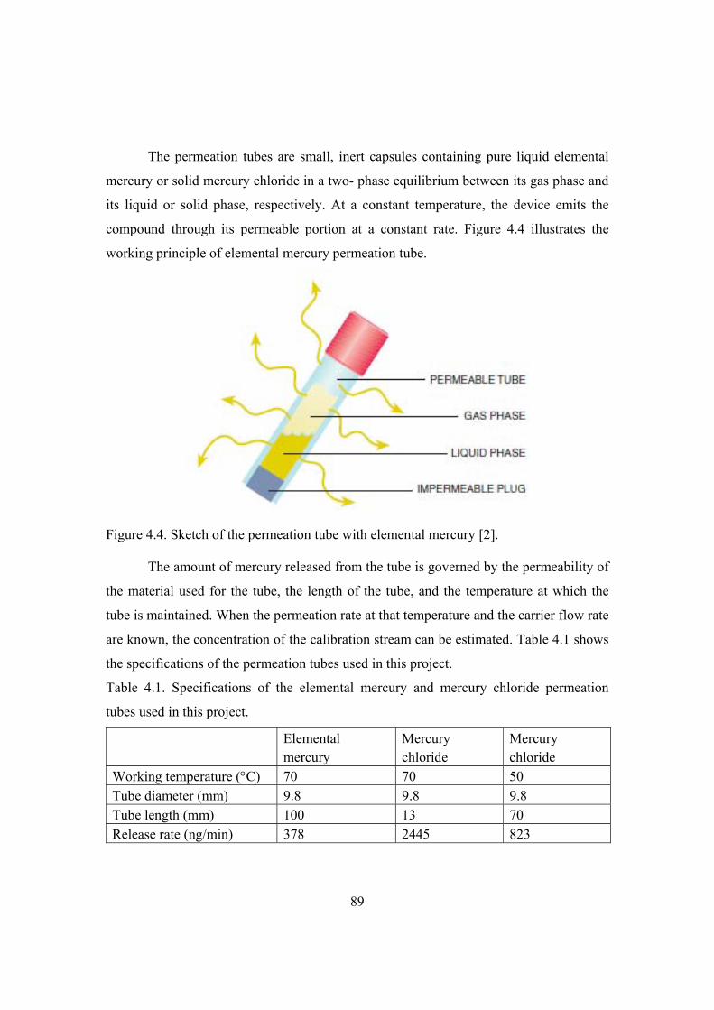
89
The permeation tubes are small, inert capsules containing pure liquid elemental
mercury or solid mercury chloride in a two- phase equilibrium between its gas phase and
its liquid or solid phase, respectively. At a constant temperature, the device emits the
compound through its permeable portion at a constant rate. Figure 4.4 illustrates the
working principle of elemental mercury permeation tube.
Figure 4.4. Sketch of the permeation tube with elemental mercury [2].
The amount of mercury released from the tube is governed by the permeability of
the material used for the tube, the length of the tube, and the temperature at which the
tube is maintained. When the permeation rate at that temperature and the carrier flow rate
are known, the concentration of the calibration stream can be estimated. Table 4.1 shows
the specifications of the permeation tubes used in this project.
Table 4.1. Specifications of the elemental mercury and mercury chloride permeation
tubes used in this project.
Elemental mercury
Mercury chloride
Mercury chloride
Working temperature (C) 70 70 50 Tube diameter (mm) 9.8 9.8 9.8 Tube length (mm) 100 13 70 Release rate (ng/min) 378 2445 823

90
It is difficult to control the release rate of the mercury chloride tube to a similar
value as the elemental mercury tube. The originally supplied mercury chloride tube has a
release rate that is five times larger than the quoted tube at 70C. After several trials
VICI can provide a tube with a release rate of 823 ng/min at 50C.
4.1.3 Humidifier for water vapor addition
The water vapor is not removed before mercury analyzer and mercury
concentration is therefore measured on a wet basis. Thus it is important to get a precise
control of the water addition.
Survey and quotation of water vapor addition methods and equipments were
carried out to get a reliable water vapor addition device. Current water addition methods
include direct liquid injection, bubblers, porous membrane contactor and non-porous
membrane contactor. The first three methods are already applied in CHEC. However,
recent studies show that fluctuation is a main problem [3,4]. Due to the small amount of
water injected in the direct injection method, it is difficult to control such small flow rate.
Water condensation test of the bubbler evaporator shows that the water saturation
fluctuates and cannot reach the calculated level [3,4]. This method is low cost, but has
inaccuracies due to the temperature of the gas and liquid, operating pressure, and liquid
level.
Porous membrane contactor uses Nafion selective permeable membrane tube and
water to continuously humidify gas streams. The producer suggests recirculation of the
water at 4% of the gas flow [5]. It is difficult to find such a small pump that works at
temperatures above 50C. Flow with greater pressure needs to be flowing inside tubes to
prevent tubing collapse. CHEC has made an evaporator using the membrane tube.
However, a lot of humidity fluctuation has been observed and the reasons have not been
identified [3,4]. Swedish company Cellkraft produces commercial evaporator using the
membrane tube [6]. The system uses similar design of CHEC’s membrane evaporator,
but has a water trap to remove water droplet. The water tank is heated from outside and
there is an integrated heating tape for the gas lines. The water level in the tank is

91
controlled and automatically filled. The producer can provide calibration curve and
guarantee for water droplet free and working properly at small carrier gas flow rate of
300 ml/min. The evaporator system without a dew point sensor costs about 64,000 DKK.
American company Rasirc produces a water vapor addition unit using the non-
porous membrane tube and integrated water temperature, level and dew point control
[7,8]. The unit purifies and controls water vapor addition for a wide range of flow rates
and process pressures. The membrane excludes particles, micro-droplet, volatile gases
and other opposite charged species and ensures only water vapor is added. Figure 4.5
illustrates the configuration of the Rasirc humidifier. Carrier gas to be humidified flows
into the humidification unit. The water is heated to match the desired dew point
temperature or humidification level. Water diffuses across the membrane to saturate the
gas to be humidified. Temperature of the humidified gas is measured and fed back to a
temperature controller to adjust the humidification level. Internal pressure control
maintains independence from variations in downstream process pressures which allows
operation into atmospheric and vacuum pressure environments. The unit with integrated
humidity sensor costs about 50,000 DKK. The Rasirc humidifier has been widely used in
the fabrication of semiconductors, nanotechnology, photovoltaics, fuel cells and other
applications [8]. After comparison, a Rasirc RHS-IP-3-HT humidifier with an internal
dew point sensor to regulate the dew point of the saturated gas was purchased.
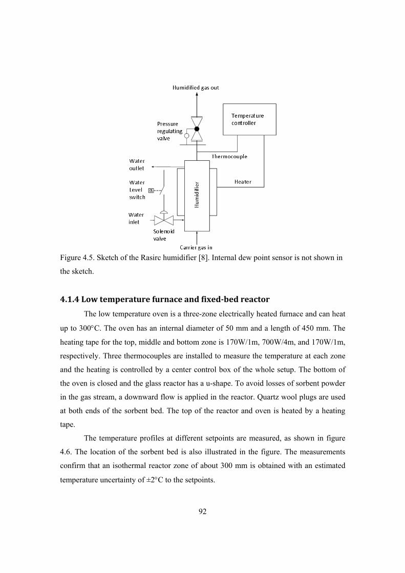
92
Figure 4.5. Sketch of the Rasirc humidifier [8]. Internal dew point sensor is not shown in
the sketch.
4.1.4 Low temperature furnace and fixedbed reactor
The low temperature oven is a three-zone electrically heated furnace and can heat
up to 300C. The oven has an internal diameter of 50 mm and a length of 450 mm. The
heating tape for the top, middle and bottom zone is 170W/1m, 700W/4m, and 170W/1m,
respectively. Three thermocouples are installed to measure the temperature at each zone
and the heating is controlled by a center control box of the whole setup. The bottom of
the oven is closed and the glass reactor has a u-shape. To avoid losses of sorbent powder
in the gas stream, a downward flow is applied in the reactor. Quartz wool plugs are used
at both ends of the sorbent bed. The top of the reactor and oven is heated by a heating
tape.
The temperature profiles at different setpoints are measured, as shown in figure
4.6. The location of the sorbent bed is also illustrated in the figure. The measurements
confirm that an isothermal reactor zone of about 300 mm is obtained with an estimated
temperature uncertainty of ±2C to the setpoints.

93
0 50 100 150 200 250 300 350 400
Distance to oven bottom (mm)
0
50
100
150
200
250
300
Ov
en t
emp
erat
ure
(oC
)
Setpoint: 250 oCSetpoint: 200 oCSetpoint: 150 oCSetpoint: 120 oC Sorbent bed
position
Figure 4.6. Temperature profile of the low temperature reactor oven.
The glass reactor applied in this project is shown in figure 4.7. The reactor has an
outer diameter of 20 mm (internal diameter of 18 mm) and a glass fiber porous plate to
hold sorbent sample. With the dimension of the reactor shown in figure 4.7, the sorbent
bed is located in the middle height of the low temperature furnace.
Figure 4.7. Pictures with dimensions for the glass reactor.
4.1.5 Mercury analysis system
The mercury analysis system consists of a Lumex RA-915 AMFG elemental
mercury analyzer, a gas distribution box and a oxidized mercury converter. Figure 4.8
illustrates the sketch of the analysis system. A photo of the analysis system is presented
in Figure 4.9.
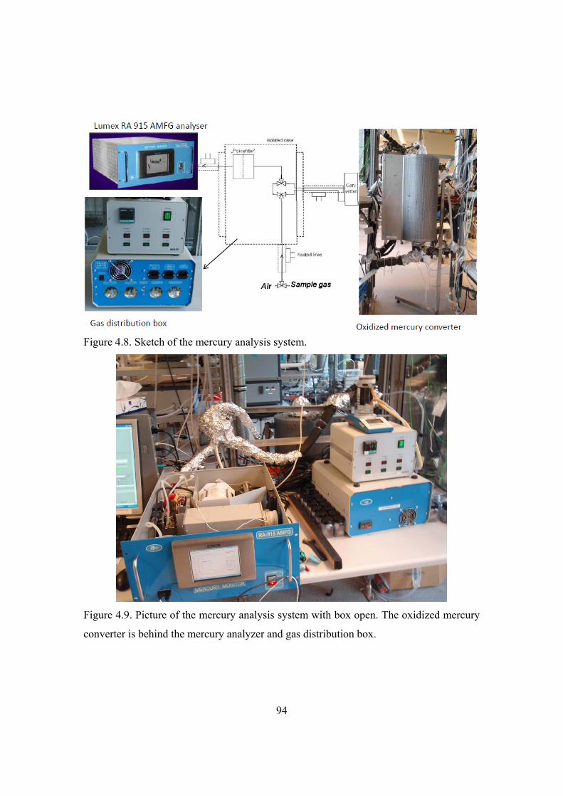
94
Figure 4.8. Sketch of the mercury analysis system.
Figure 4.9. Picture of the mercury analysis system with box open. The oxidized mercury
converter is behind the mercury analyzer and gas distribution box.
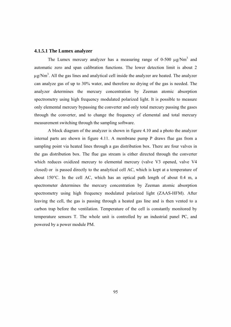
95
4.1.5.1 The Lumex analyzer
The Lumex mercury analyzer has a measuring range of 0-500 g/Nm3 and
automatic zero and span calibration functions. The lower detection limit is about 2
g/Nm3. All the gas lines and analytical cell inside the analyzer are heated. The analyzer
can analyze gas of up to 30% water, and therefore no drying of the gas is needed. The
analyzer determines the mercury concentration by Zeeman atomic absorption
spectrometry using high frequency modulated polarized light. It is possible to measure
only elemental mercury bypassing the converter and only total mercury passing the gases
through the converter, and to change the frequency of elemental and total mercury
measurement switching through the sampling software.
A block diagram of the analyzer is shown in figure 4.10 and a photo the analyzer
internal parts are shown in figure 4.11. A membrane pump P draws flue gas from a
sampling point via heated lines through a gas distribution box. There are four valves in
the gas distribution box. The flue gas stream is either directed through the converter
which reduces oxidized mercury to elemental mercury (valve V3 opened, valve V4
closed) or is passed directly to the analytical cell AC, which is kept at a temperature of
about 150°C. In the cell AC, which has an optical path length of about 0.4 m, a
spectrometer determines the mercury concentration by Zeeman atomic absorption
spectrometry using high frequency modulated polarized light (ZAAS-HFM). After
leaving the cell, the gas is passing through a heated gas line and is then vented to a
carbon trap before the ventilation. Temperature of the cell is constantly monitored by
temperature sensors T. The whole unit is controlled by an industrial panel PC, and
powered by a power module PM.
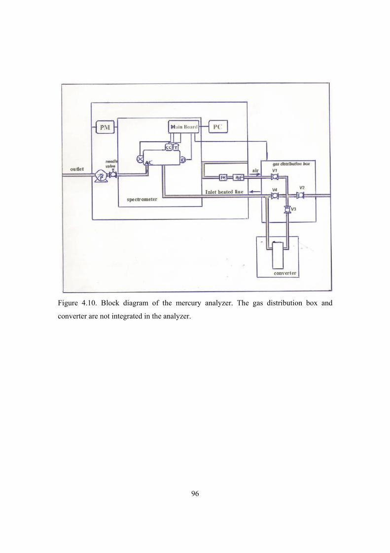
96
Figure 4.10. Block diagram of the mercury analyzer. The gas distribution box and
converter are not integrated in the analyzer.

97
Figure 4.11. Photo of the analyzer internal parts.
The measurement principle of the analyzer is illustrated in figure 4.12 [9]. A
mercury electronic discharge lamp is placed in a strong magnetic field H, by which the
mercury resonance line at 254 nm is split into the three polarized Zeeman components -,
, and +. Only the -components of the electromagnetic radiation will be registered by
the photo detector D. - and + are separated by a polarization modulator. As long as
mercury vapor is absent in the multipath cell, the intensities of both -components are
equal. When mercury is admitted to the cell, the difference in intensities between the two
-components increases as a function of the mercury concentration. As the spectral shift
between the -components is significantly smaller than the widths of molecular
absorption bands and scattering spectra, background absorption by interfering
compounds can be neglected.

98
Figure 4.12. Illustration principle of the Zeeman atomic absorption spectrometry using
high frequency modulated polarized light (ZAAS-HFM) [9].
Sample gas connection to the analyzer is maintained at ambient pressure, with
any excess flow vented to the atmosphere. Heated inlet and outlet lines are connected to
the analytical cell inside the analyzer by means of 6 mm Swagelok-type fittings. The
analyzer requires between 1 and 12 l/min of sample gas at all times and the flow can be
controlled by the needle valve before the pump.
4.1.5.2 Gas distribution box
The gas distribution box contains valves for switching the gas and air to the
analyzer and converter. The valves are controlled by the sampling software. The box is
heat traced and isolated. There is a switch valve before the gas distribution box. Addition
of air or sample gas to the analysis system can be selected.

99
4.1.5.3 The oxidized mercury converters
Two converters are used in this project. Originally Lumex supplied a low
temperature converter for the red brass catalyst. Figure 4.13 shows a picture of the
converter with a glass container loaded with red brass chips. The converter is designed to
work at 180C and the highest temperature is about 250C. The glass container has an
outer diameter of 20 mm and can hold about 20 g red brass chips.
Figure 4.13. Picture of the low temperature converter with a glass container loaded with
20 g red brass chips.
Later a high temperature converter was used for the sulfite based converter
material. The high temperature oven is a three-zone electrically heated furnace with a
quartz reactor, which has an inner diameter of 17 mm and can hold up to 30 g sulfite-
based converter pellets. The converter is a fixed-bed reactor made of quartz as shown in
figure 4.14. The inner and bottom tubes of the reactor were removable. The sulfite-based
pellets are placed on the porous quartz plate. The converter temperature is measured
below the porous quartz plate by a thermocouple shielded in a quartz tube.

100
Figure 4.14. Sketch of the high temperature converter with quartz reactor in the furnace.
4.2 Converter and sorbent materials
The red brass chips are obtained through Lumex. The idea of using red brass at
low temperature is to bind free halogens in the flue gas and thus prevent back reaction
into mercury halides and corrosion problem caused by SO2 oxidation at high
temperatures [10]. Figure 4.15 shows picture of the red brass chips which have a
thickness of about 0.5 mm and are rolled to a diameter of about 2 mm and a length of
about 10 mm.
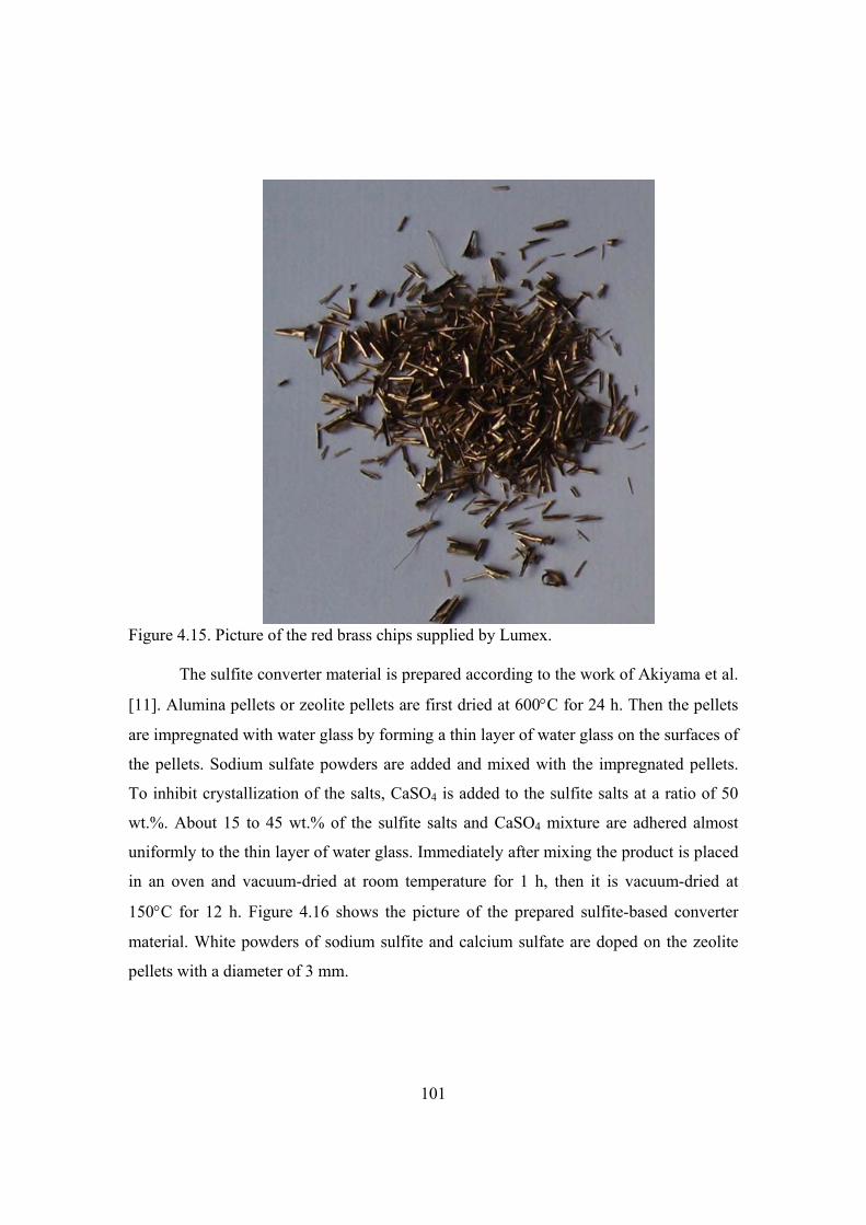
101
Figure 4.15. Picture of the red brass chips supplied by Lumex.
The sulfite converter material is prepared according to the work of Akiyama et al.
[11]. Alumina pellets or zeolite pellets are first dried at 600C for 24 h. Then the pellets
are impregnated with water glass by forming a thin layer of water glass on the surfaces of
the pellets. Sodium sulfate powders are added and mixed with the impregnated pellets.
To inhibit crystallization of the salts, CaSO4 is added to the sulfite salts at a ratio of 50
wt.%. About 15 to 45 wt.% of the sulfite salts and CaSO4 mixture are adhered almost
uniformly to the thin layer of water glass. Immediately after mixing the product is placed
in an oven and vacuum-dried at room temperature for 1 h, then it is vacuum-dried at
150C for 12 h. Figure 4.16 shows the picture of the prepared sulfite-based converter
material. White powders of sodium sulfite and calcium sulfate are doped on the zeolite
pellets with a diameter of 3 mm.

102
Figure 4.16. Picture of the prepared sulfite-based converter material.
To be able to quantify the oxidized mercury reduction efficiency, the oxidized
mercury is produced by passing the flue gas with known concentration of elemental
mercury to the reactor with 4 g catalyst for selective catalytic reduction of NOx. The
catalyst piece was cut from a corrugated-type monolith obtained from Haldor Topsøe
A/S. The catalyst is based on a fiber reinforced titania (TiO2) carrier, which is
impregnated by vanadium (V2O5) and tungsten (WO3). The vanadium loading (3 wt.%
V2O5) was uniformly distributed across the wall thickness of the monolith [12,13]. The
efficiency of the converter is evaluated by the recovery extent of measured total mercury
through the SCR catalyst and converter compared to the elemental mercury level at the
inlet of the SCR catalyst.
The most investigated sorbents in this project is Darco Hg activated carbon,
which is a commercial lignite based powdered activated carbon and is developed for
heavy metal removal from incinerators and power plants. The Darco Hg carbon has a
bulk density of 0.51 g/cm3 and a surface area of about 600 m2/g. The average particle

103
size is 16 m and the porosity is about 58% [14-22]. Properties of other sorbents are
presented in the chapter of sorbent screening.
4.3 Flue gas composition
The total flow rate through the reactor is 2.75 Nl/min of which about 2 Nl/min is
passed through the analyzer. The typical composition of the simulated cement kiln flue
gas applied in this work includes 21% CO2, 6% O2, 1% H2O, 10 ppmv HCl, 1000 ppmv
NO, 23 ppmv NO2, and 1000 ppmv SO2. The applied mercury concentration is about
160-180 µg/Nm3 by keeping the elemental mercury and mercury chloride source at 70ºC
and 50ºC, respectively, and using 0.275 Nl/min nitrogen as carrier gas. The water level in
the simulated flue gas is lower than real level in the cement kiln flue gas. This is due to
the limitation of the humidifier. Although the humidifier can add water vapor relatively
precisely, it is not robust. The membrane can be easily broken and the unit cannot stand
high over pressure. After short period of operation, the unit was repaired twice by
changing the membrane and installing of a pressure release valve. It seems that the unit
can run properly only for short period. Another reason is the fluctuation measurement of
the mercury analyzer with more than 5% water in the simulated flue gas. Therefore it is
decided to use 1% water in most of the tests by adding water through a bubbling bottle.
In few cases high water contents are used to cover a wide range of water level in the
simulated flue gas.
4.4 Sorbent load in fixedbed test
For the applied reactor in this project, at least 500 mg activated carbon is need to
form a fixed-bed covering the cross area of the reactor. The amount of the sorbent sample
is determined by the sample saturation time. Literature reported that approximately 600
mg of sorbent initially was placed into the reactor; however, the samples were reduced
from 600 mg to between 100 and 150 mg after it was observed that extremely long
durations (up to weeks) would be required to saturate the larger quantity of sorbent [23].
To avoid channeling the sorbent sample is usually mixed with some inert materials such

104
as sand and glass beads. Application of dilution by sand powder can also accelerate the
tests. The reaction gas flows downward through the bed to minimize the chance of
selective flow or channeling through the bed. Reactor sizes and sample dilutions applied
in the literature are reviewed and summarized in table 4.2.
Table 4.2. Reported reactor sizes, flow rates and sorbent sample loads in the literature.
Sorbent loading Reactor
size
ID (mm)
Flow rate
(Nl/min)
Superficial
velocity (cm/s)
@150C
References
50 mg fly ash mixed with 3 g
glass beads, 2.5 mm bed
thickness, additional 57.5 mm
glass beads upstream to the bed
for better flow distribution
35 3.2 8.7 [24]
0.2-0.6 g sample (copper
compound based sorbents and
commercial proprietary sorbents)
held by a glass wool plug, 16 mm
bed thickness
4 0.15 30.8 [25]
20-30 mg sorbent (Norit FGD
carbon and functionalized silica)
in 6 g silica, glass fiber filter at
two ends
12.7 0.91 18.4 [26]
0.61 g Darco G60 carbon with 3 g
glass beads, 4 mm bed length
35 2.8 7.5 [27]
20 mg activated carbon mixed
with 1 g sand
6.35 0.17 13.8 [28]
5 mg carbon on 3 g glass beads, 4
mm bed thickness
35 4.2 7.52 [29]
20 mg carbon in 10 g sand,
supported by quartz wool
12.7 1 20.3 [30]
10-100 mg sorbent mixed with 2
g sand, bed thickness of about 5
mm, quartz wool at two ends
18 2.75 22.1 This work

105
4.5 Experimental procedure
An experimental procedure is developed for sorbent tests and measures are taken to
avoid mercury accumulation in the system. The detailed procedure is as following:
The mercury source is maintained at the operating temperature with carrier gas through all the time.
Increase the sulfite converter temperature setpoints from 100C to 500C.
Check the temperatures of mercury source, heated lines, low temperature oven,
gas distribution box and analyzer, set the low temperature reactor oven to desired
temperature.
Weight desired amount of sorbent and mix with 2g sand powder, load the sample
to the glass reactor.
Check and measure the flow rates of different gases.
When the converter temperature reaches 500C for about 30 min, change the
mercury analyzer measurement mode from elemental to total mercury
measurement.
Switch the valve before the glass reactor to bypassing the reactor position; add
gases except mercury to the system.
Add the gases to the mercury analyzer to check whether there is some mercury
accumulated in the hot system; if there is some mercury detected, wait the
mercury reading decreases to zero value and then switch mercury source to the
system.
Start the test and data sampling, make note in the sampling program, measure the
mercury inlet concentration for at least 30 min to ensure that the glass reactor is
heated for about 1 h and stable reactor temperature is obtained.
Switch the gases to fixed sorbent bed, make note in the sampling program.
After full mercury breakthrough is observed for 30 min, switch air to the analyzer
system while keeping simulated flue gas to the reactor, and switch the mercury
analyzer to measure elemental mercury.
106
When the elemental mercury measurement mode is ready, switch the simulated
flue gas to the analysis system.
After 20 min, switch the simulated flue gas to bypass the reactor and measure the
inlet mercury concentration for another 20 min.
Stop the test, switch air to the analysis system, switch mercury source to the
carbon trap and ventilation, and stop other gases.
Remove the reactor from the oven and remove the sample after the reactor is
cooled, store the sample in a closed plastic bottle with label.
At the end of the day, turn all gases off except nitrogen and H2O when elemental
mercury source is applied and add also HCl when mercury chloride is applied to
flush the system overnight. Decrease the converter temperature to 100C, to
ensure the mercury analyzer is in elemental mercury measurement mode and air
is added to the analysis system.
Always keep the whole reactor system hot.
4.6 Sorbent characterization
4.6.1 Scanning electron microscopy
Scanning electron microscopy with energy-dispersive X-ray spectroscopy (SEM-
EDX) analysis is used to understand mercury capture mechanisms by different powder
sorbent. The main goals of the SEM-EDX analysis is to study the sorbents’ topography
(surface features), morphology (shape and size), and composition. Morphology study
will be used to identify particle agglomeration and compare with particle size
measurement.
The SEM-EDX analysis is conducted at Center for Electron Nanoscopy, DTU.
Micrographs and EDX analysis of carbon samples are carried out using Quanta FEGSEM
200F. The carbon samples are not coated, while the non-carbon samples are coated with
14 nm carbon and analyzed on Inspect ‘S’ SEM. The FEGSEM is a high resolution
flexible microscope with field emission gun (FEG). The Inspect ‘S’ is a scanning
electron microscope with a tungsten filament electron source. To support the surface

107
information obtained by the imaging detectors both SEMs are equipped with Oxford
Instruments INCA EDX analyzer which gives possibilities to analyze chemical elements
position on the sample surface in single spots or over a selected area. The microscope can
operate in as well high- and low vacuum as in environmental mode. A typical working
distance of 10 mm is applied.
A thin layer of sample powders is spread on a double sided conductive carbon
table. If particles are piled on each other charge-up easily takes place, causing them to
move during observation. A low accelerating voltage of 5 kV is applied during imaging
on the FEGSEM to obtain detailed information on the particle surface and minimize
specimen charging problem.
4.6.2 Particle size distribution
The particle size distributions of the sorbent powders are analyzed by a Malvern
Mastersizer S analyzer using laser diffraction. The technique of laser diffraction is based
around the principle that particles passing through a laser beam will scatter light at an
angle that is directly related to their size. Large particles scatter light at narrow angles
with high intensity [31], whereas small particles scatter at wider angles but with low
intensity. The analyzer consists of a laser to provide a source of coherent, intense light of
fixed wavelength, a sample presentation system to ensure that the material under test
passes through the laser beam as a homogeneous stream of particles in a known,
reproducible state of dispersion, and a series of detectors which are used to measure the
light pattern produced over a wide range of angles.
Based on previous analysis experience at CHEC, the samples are dispersed either
in ethanol or distilled water for one minute before measurement to avoid agglomeration
and the result is the average of 5 measurements.

108
4.6.3 Analysis of mercury in sorbent
Mercury content in the exposed sorbent is analyzed by a DMA-80 analyzer from
Milestone at FLSmidth Dania lab. 100 mg of powder sample is first weighted and loaded
in a sample boat. The boats are transported automatically into the furnace. The sample is
initially dried and then thermally decomposed in a continuous flow of oxygen.
Combustion products are carried off and further decomposed in a hot catalyst bed [32].
Mercury vapors are trapped on a gold amalgamator and subsequently desorbed for
quantization. The mercury content is determined using an atomic absorption
spectrophotometer at 254 nm. The instrument determines the absolute amount of Hg and
then the software calculates its concentration in the sample.
4.7 References
[1] VICI Metronics Inc., Dynacalibrator® Model 150 calibration gas generator brochure, 2008.
[2] VICI Metronics Inc., Dynacal permeation tubes, 2011.
[3] B. Maribo-Mogensen and J. Christensen, Internal steam reforming in solid oxide fuel cells,
Bachelor, Department of Chemical and Biochemical Engineering, Technical University of
Denmark, 2008.
[4] A.F. Castells. Steam reforming kinetics over Ni-YSZ used as anode material for solid fuel
cells, Master, Department of Chemical and Biochemical Engineering, Technical University of
Denmark, 2009.
[5] Perma Pure, MHTM-series humidifier user manual, http://www.permapure.com /PDF%20Files
/MH%20Manual.pdf, accessed March/20, 2009.
[6] Cellkraft AB, P-series humidifier manual, http://www.cellkraft.se/humidity_and_steam/P-
Series.html, accessed March 20, 2009.
[7] RASIRC, RASIRC RainmakerTM humidification system manual, http://www.rasirc.com
/resources/datasheets/datasheet_RASIRC_RainMaker_HS.pdf, accessed March 20, 2009.
[8] Jeffrey Spiegelman, RainMaker humidification system for precise delivery of water vapor
into atmospheric and vacuum applications, http://www.rasirc.com/resources/whitepapers
/whitepaper_RHS.pdf, accessed March 20, 2009.
[9] Lumex Ltd, RA-915 AMFG automatic mercury monitor for flue gas operational manual,
2009.
[10] R. Kanefke, H. Köser, B. Vosteen, F. Kristina, B. Frank, S. Raik, Method for the production
of elemental mercury from mercury compounds, patent WO 2008/064667 A2, 2008.

109
[11] S. Akiyama, J. Kato, F. Koga, K. Ishikawa, Catalysts for reducing mercury, a mercury
conversion unit, and an apparatus for measuring total mercury in combustion exhaust gas by
using the same, patent US2007/0232488 A1, 2007.
[12] Y. Zheng, A.D. Jensen, J.E. Johnsson, Deactivation of V2O5-WO3-TiO2 SCR catalyst at a
biomass-fired combined heat and power plant, Applied Catalysis B: Environmental. 60 (2005)
253-264.
[13] Y. Zheng, A.D. Jensen, J.E. Johnsson, J.R. Thøgersen, Deactivation of V2O5-WO3-TiO2
SCR catalyst at biomass fired power plants: Elucidation of mechanisms by lab- and pilot-scale
experiments, Applied Catalysis B: Environmental. 83 (2008) 186-194.
[14] H.C. Hsi, S. Chen, M. Rostam-Abadi, M.J. Rood, C.F. Richardson, T.R. Carey, R. Chang,
Preparation and evaluation of coal-derived activated carbons for removal of mercury vapor from
simulated coal combustion flue gases, Energy & Fuels. 12 (1998) 1061-1070.
[15] M. Rostam-Abadi, S.G. Chen, H.C. Hsi, M. Rood, R. Chang, T.R. Carey, B. Hargrove, C.
Richardson, W. Rosenhoover, F. Meserole, Novel vapor phase mercury sorbents, Proceedings of
the EPRI-DOE-EPA Combined Utility Air Pollutant Control, Washington, DC, Aug 25–29,1997.
[16] T.R. Carey, O.W. Hargrove Jr, C.F. Richardson, R. Chang and F.B. Meserole, Factors
affecting mercury control in utility flue gas using sorbent injection, Proceedings of the Air &
Waste Management Association's 90th Annual Meeting, Toronto, Ontario, Canada, June 8-13,
1997.
[17] B. Ghorishi and B.K. Gullett, Fixed-bed control of mercury: Role of acid gases and a
comparison between carbon-based, calcium-based, and coal fly ash sorbents, Proceedings of the
EPRI/DOE/EPA Combined Utility Air Pollutant Control Symposium, Washington, DC, August
25–29,1997.
[18] S.B. Ghorishi and C.B. Sedman, Combined mercury and sulfur oxides control using
calcium-based sorbents, Proceedings of the EPRI-DOE-EPA Combined Utility Air Pollutant
Control Symposium, Washington, DC, August 25–29, 1997.
[19] S.B. Ghorishi and B.K. Gullett, An experimental study on mercury sorption by activated
carbons and calcium hydroxide, The Fifth Annual North American Waste-to-Energy Conference,
Research Triangle Park, NC, 22-25 April, 1997.
[20] N. Hutson, C. Singer, C. Richardson, J. Karwowski and C. Sedman, Practical applications
from observations of mercury oxidation and binding mechanisms, EPRI-DOE-EPA-AWMA
Combined Power Plant Air Pollutant Control Mega Symposium, Washington DC, August 30 -
September 2, 2004.
[21] Norit Americas Inc., Datasheet of Darco FGD powdered activated carbon, 2008.
[22] R. Bhardwaj. Impact of temperature and flue gas components on mercury speciation and
uptake by activated carbon sorbents. Master thesis. University of Pittsburgh, 2007.
[23] D.J. Hassett, K.E. Eylands, Mercury capture on coal combustion fly ash, Fuel. 78 (1999)
243-248.

110
[24] D. Karatza, A. Lancia, D. Musmarra, Fly ash capture of mercuric chloride vapors from
exhaust combustion gas, Environ. Sci. Technol. 32 (1998) 3999-4004.
[25] J.W. Portzer, J.R. Albritton, C.C. Allen, R.P. Gupta, Development of novel sorbents for
mercury control at elevated temperatures in coal-derived syngas: results of initial screening of
candidate materials, Fuel Processing Technology. 85 (2004) 621-630.
[26] J.Y. Lee, Y. Ju, T.C. Keener, R.S. Varma, Development of cost-effective noncarbon
sorbents for Hg0 removal from coal-fired power plants, Environ. Sci. Technol. 40 (2006) 2714-
2720.
[27] D. Karata, A. Lancia, D. Musmarra, F. Pepe, Adsorption of metallic mercury on activated
carbon, Symposium (International) on Combustion. 26 (1996) 2439-2445.
[28] G. Skodras, I. Diamantopoulou, G. Pantoleontos, G.P. Sakellaropoulos, Kinetic studies of
elemental mercury adsorption in activated carbon fixed bed reactor, Journal of Hazardous
Materials. 158 (2008) 1-13.
[29] D. Karatza, A. Lancia, D. Musmarra, C. Zucchini, Study of mercury absorption and
desorption on sulfur impregnated carbon, Experimental Thermal and Fluid Science. 21 (2000)
150-155.
[30] T.R. Carey, O.W. Hargrove Jr, C.F. Richardson, R. Chang, F.B. Meserole, Factors affecting
mercury control in utility flue gas using activated carbon, Journal of the Air & Waste
Management Association. 48 (1998) 1166.
[31] Malvern Instruments Ltd, Understanding how laser diffraction works,
http://www.malvern.com/LabEng/technology/laser_diffraction/laser_diffraction.htm, accessed
January/3, 2011.
[32] Milestone Srl, DMA-80: Principle of operation, http://www.milestonesrl.com
/analytical/products-mercury-determination-dma-80-and-dma-803-principle-of-operation.html,
accessed January 6, 2011.
[33] A. Ocklind. Calculation from gas dewpoint to water content, 2009.
[34] R.H. Perry, D.W. Green, J.O. Maloney, (Eds.), Perry’s chemical engineers’ handbook, 7th
ed. The McGraw-Hill Companies, Inc., 1997.
Appendix
4A Check of mercury analyzer
Since many valves and fittings are used in the mercury analysis system, it is
important to make a leakage test of the system. Lumex service technicians performed the
leakage test. The Lumex analyzer cannot stand high pressure and the system therefore
cannot be tested by plugging the system and checking the pressure change. Instead, flow
rates at the gas distribution box, converter, and analyzer are measured simultaneously
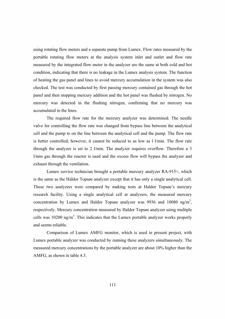
111
using rotating flow meters and a separate pump from Lumex. Flow rates measured by the
portable rotating flow meters at the analysis system inlet and outlet and flow rate
measured by the integrated flow meter in the analyzer are the same at both cold and hot
condition, indicating that there is no leakage in the Lumex analysis system. The function
of heating the gas panel and lines to avoid mercury accumulation in the system was also
checked. The test was conducted by first passing mercury contained gas through the hot
panel and then stopping mercury addition and the hot panel was flushed by nitrogen. No
mercury was detected in the flushing nitrogen, confirming that no mercury was
accumulated in the lines.
The required flow rate for the mercury analyzer was determined. The needle
valve for controlling the flow rate was changed from bypass line between the analytical
cell and the pump to on the line between the analytical cell and the pump. The flow rate
is better controlled; however, it cannot be reduced to as low as l l/min. The flow rate
through the analyzer is set to 2 l/min. The analyzer requires overflow. Therefore a 3
l/min gas through the reactor is used and the excess flow will bypass the analyzer and
exhaust through the ventilation.
Lumex service technician brought a portable mercury analyzer RA-915+, which
is the same as the Haldor Topsøe analyzer except that it has only a single analytical cell.
These two analyzers were compared by making tests at Haldor Topsøe’s mercury
research facility. Using a single analytical cell at analyzers, the measured mercury
concentration by Lumex and Haldor Topsøe analyzer was 9936 and 10080 ng/m3,
respectively. Mercury concentration measured by Haldor Topsøe analyzer using multiple
cells was 10200 ng/m3. This indicates that the Lumex portable analyzer works properly
and seems reliable.
Comparison of Lumex AMFG monitor, which is used in present project, with
Lumex portable analyzer was conducted by running these analyzers simultaneously. The
measured mercury concentrations by the portable analyzer are about 10% higher than the
AMFG, as shown in table 4.3.

112
Table 4.3. Comparison of mercury measurement by the portable Lumex RA-915+ and
the Lumex AMFG analyzer applied in this project.
Concentration measured by portable analyzer, g/Nm3
Concentration measured by AMFG analyzer, g/Nm3
Ratio of portable/AMFG
249 220 1.13 217 201 1.08 153 137 1.11
Lumex said that the difference is caused by different conditions used during
calibration at the factory and test at CHEC lab. The gas lines before the analyzer at the
factory was not heated and the analytical cell was tested at a temperature which was
50C lower than at CHEC lab. Since comparison with Haldor Topsøe analyzer shows
that the portable analyzer works properly, the AMFG is calibrated using linearity test. A
factor of 1.10 was used as the calibration coefficient.
4B Water addition verification
To verify the water addition stability and accuracy condensation tests are
conducted. The configuration of the test system is shown in figure 4.17. A water column
of a height of about 500 mm is hanged 1 m above the humidifier as water source. The top
of the water column is open. A stop valve is installed below the water column to allow
disconnection of the water column for weight measurement. Nitrogen is used as the
carrier gas. The water level in the humidifier is always kept at full level by a liquid level
switch and a micro pump. The gas line between the humidifier and the condensation
water bottle is heated at 110C to avoid water condensation in the gas line. The water
bath temperature is kept at 4C. The condensation bottle is filled with some water to
enhance the heat exchange and capture of water. It takes about 70 min for the humidifier
to reach the desired dew point. During this period the gas is bypassed to the water bath
and passes through a water bottle before ventilated. When the desired dew point is
reached and stabilized, the water tank is disconnected for weight measurement. The gas
is still running through the humidifier and water is continuously added. During the

113
measuring of the water tank weight about 80 mm water inside the ¼’’ Teflon tube is
added and the corresponding weight is about 1 g. When the water tank is connected back
there will be an 80 mm air plug inside the Teflon tube. This means that 1 g water is not
added and should be deducted from the theoretical calculation for comparison with the
measured water addition. The amount of water added can be evaluated either by
measuring weight change of the water tank or weight of water collected in the
condensation bottles.
Figure 4.17. Sketch of the condensation test system.
When the dew point is reached and stabilized, the dew point reading of the
saturated gas is changing about 0.1C from the set point. This indicates that the relative
humidity of the gas is quite stable and close to 100%.
To calculate the amount of water added the saturated water vapor pressure at
given dew point should be calculated first. Table and figure of saturated water vapor
pressure can be readily found in text book. The saturated water vapor pressure can be
calculated by using the empirical expression from Cellkraft, which is a Swedish
membrane humidifier produce [6,33]:
114
3 5 2 7 3 9 4 13 5
16 6 18 7 22 8 25 9
10.4592 4.05 10 4.18 10 3.69 10 1.02 10 8.65 10
9.04 10 2.00 10 7.79 10 1.91 10 3968.06 /( 39.57)
slnP T T T T T
T T T T T
(4.1) where the water saturated water vapor pressure Ps is in MPa, T is in K.
Partial pressures of the gases are proportional to the gas flow rates:
2 2
2 2
H O H O
N N
P F
P F (4.2)
2 2tot H O NP P P (4.3)
where T is the desired dew point of the gas, 82 C, 355.15 K 3 5 2 7 3
9 4 13 5 16 6 18 7
22 8 25 9
10.4592 4.05 10 355.15 4.18 10 355.15 3.69 10 355.15
1.02 10 355.15 8.65 10 355.15 9.04 10 355.15 2.00 10 355.15
7.79 10 355.15 1.91 10 355.15 3968.06 /( 355.15 39.5
slnP
7) 2.9686 (4.4) and 513.76sP mbar
With room temperature of 25C, carrier nitrogen flow, 0.3l/min, equals 0.275 Nl/min,
one can calculate:
Water addition rate (g/min):
(18 / 22.4) 0.275 (513.76 /1013.25)0.227
1 513.76 /1013.25
Water flow rate (Nl/min):
0.275 (513.76 /1013.25)0.283
1 513.76 /1013.25
The water vapor pressure can also be calculated using Antoine equation [34]:
10 8.07131 1730.63/(233.426 )sPlog T (4.5)
where Ps is in Torr (1 mmHg), T is in C.
10 8.07131 1730.63 /(233.426 82) 2.5847sPlog
then 512.35sP mbar
Calculated water addition rate (g/min):
(18 / 22.4) 0.275 (512.35 /1013.25)0.226
1 513.76 /1013.25
Water flow rate (Nl/min):

115
0.275 (512.35 /1013.25)0.281
1 513.76 /1013.25
Table 4.4 presents the calculated water addition rates and flow rates at different
dew points. Calculations using Cellkraft equation and Antoine equation give almost the
same results.
Table 4.4. Calculated water addition rate and flow rate at different dew points. Cellkraft equation Antoine equation Dew point (C)
H2O addition rate (g/min)
H2O flow rate (Nl/min)
H2O addition rate (g/min)
H2O flow rate (Nl/min)
82 0.227 0.283 0.226 0.281 77 0.156 0.194 0.155 0.193 72 0.112 0.139 0.111 0.138 63 0.064 0.080 0.064 0.080 4 0.002 0.002 0.002 0.002
The comparison between the measured water addition and calculated water
addition is presented in table 4.5. For the first two tests only one condensation bottle is
used and about 1/3 of the bottle is filled with water. The water collected in the
condensation bottle is only 50-60% of the calculated value. This is probably due to the
short gas residence time in the condensation bottle and small amount of water filled in
the condensation bottle. The amount of water added by water tank weight measurement
is reasonably in agreement with the calculation. Later more water is filled in the bottle
and two or four bottles are connected in series. Then the amounts of water added by
measuring the water tank weight change and water collected in the bottle are similar and
about 90-95% of the calculated values. For the four bottle in-series tests the weight
change of each bottle is measured. Almost all the water is collected in the first bottle and
the water collected in other bottles is negligible. The test results show that the humidifier
works well.

116
Table 4.5. Comparison between the measured water addition and calculated water
addition.
Dew point (C) 82 82 82 82 82 82 N2 flow (ml/min) 300 300 300 300 300 400 Room temp. (C) 24.9 24.7 26.3 25.7 24.9 24.9 Duration (min) 450 318 368.5 240 143 120 Calculated water addition (g) 100.25 70.55 82.17 52.52 28.89 35.12 Measured water addition through tank weight (g)
102.4 63.5 74.10 47.7 27.6 31.8
Measured/calculated (%) 102 90 90.5 90.8 95.5 90.6 Measured water addition through collection in water bottle (g)
61.48 36.27 73.99 47.08 - 32.32
Water bottle number 1 1 2 2 4 2 Measured/calculated (%) 61.4 51.4 90.3 89.6 - 92

117
5
Dynamic measurement of mercury adsorption and
oxidation on activated carbon in simulated cement
kiln flue gas
This chapter starts with a review of available gaseous mercury measurement
technologies. Pros and cons of the technologies will be discussed. Then tests of the
commercial red brass converter in simulated cement kiln flue gas are presented. Finally
development of sulfite-based converter for oxidized mercury reduction in simulated
cement kiln flue gas is reported. Suggestions for practical applications of the sulfite
converter in both lab and cement plants are presented.
5.1 Review of gaseous mercury measurement technology
Presently, the accepted methods for mercury measurement are wet-chemistry
procedures such as EPA methods 29 and 101 A for total mercury measurement and the
Ontario Hydro method for total mercury and speciation measurement [1,2]. These
methods often have 2-week or more turn-around time for results. The sorbent trap
method was developed to shorten the analysis time of the collected samples. These
methods can only provide an average mercury concentration over a 1-2 hour period, and
cannot characterize the variability in mercury emissions due to process and operating
changes with time.
To obtain an understanding of the process of mercury removal by sorbent
injection upstream of a fabric filter, it is necessary to study them under more controlled
conditions such as in a laboratory scale setup, for example using a fixed bed reactor. In
such experiments it is also necessary to use a continuous emission monitor (CEM) to
118
obtain knowledge of uptake of total and speciated mercury in simulated flue gas to fully
evaluate the control technologies under development. Fixed-bed experiments have been
used by many laboratories to test the relative effectiveness of different mercury sorbents.
The critical assumption of this experimental method is that the performance of a sorbent
over a long exposure time (hours) reflects the filtration/reaction on bags, where the
sorbent contacts the flue gas for about 25 minutes [1]. Therefore, it is preferable to verify
this assumption by supplementing the final mercury content data with breakthrough data
obtained using a CEM.
Real- or near-real-time mercury emission measurement can in principle be
obtained depending on the applied detection method. Generally, real-time measurements
can be achieved by analyzers using cold vapor atomic absorption spectroscopy. The cold
vapor atomic fluorescence spectrophotometer collects mercury in flue gas on alternating
gold traps and thermally desorbs the mercury in about five minute intervals allowing for
semi-continuous measurements [3].
Available commercial mercury analyzers can only measure elemental mercury.
The measurement of total mercury as well as mercury speciation can only be achieved
indirectly. For this purpose, all oxidized mercury is reduced to its elemental form by a
converter system. It should be noted that the technology for the analytical part of the
detection system is somehow matured and provides accurate and sensitive detection of
elemental mercury [3]. The conversion unit, on the other hand, is a subject of continuing
research and improvement efforts [2].
The converter can be based either on wet chemistry or dry conversion. In a wet-
chemistry conversion unit the Hg2+ is converted to Hg0 via a liquid phase reducing agent,
often stannous chloride (SnCl2), prior to entering the analysis unit. There is interference
with SO2, which can affect the reduction of Hg2+ when using SnCl2 [2,4,5]. Furthermore,
the wet chemicals themselves are very corrosive and need frequent replenishment.
For on-line measurements, a dry converter is usually preferred over a wet
chemical converter for the reasons mentioned above [6]. Several dry converter types
exist. In a pure thermal conversion unit, the flue gas is heated to reduce all Hg2+ to Hg0.

119
However, reoxidation of the reduced mercury before reaching the analysis unit is a
concern. Furthermore, the required temperature depends on the HCl concentration in the
gas. In case of a thermocatalytic conversion, the potential short lifetime of the catalyst is
an issue due to the possible poisoning by acidic gases in the sample gas [2,4,5].
Compared to mercury measurements in power plants and waste incinerators, there
is a lack of experience related to continuous measurement of mercury emissions from
cement kilns. Furthermore, the experience gained from power plant and waste incinerator
may not be applied directly to cement plant due to the different process conditions and
flue gas compositions [7]. In this work a commercial red brass converter, which is
developed for application in waste incinerators, is tested in simulated cement kiln flue
gas and an improved sodium sulfite-based converter is developed and tested.
5.2 Performance test of the mercury analyzer
The analyzer has an internal mercury source for span calibration. However, the
span calibration is conducted at an elemental mercury concentration of about 16 g/Nm3,
which is much lower than typical mercury concentration of about 180 g/Nm3 applied in
this project. If the linearity of the analyzer is poor then the measured mercury
concentration at typical mercury levels in this project could be wrong. To check the
analyzer linearity some tests were conducted. The carrier nitrogen flow rate through the
mercury source was kept at 275 Nml/min. Firstly, the mercury concentration in the outlet
gas from the mercury source was calculated using the measured mercury concentration in
the mixed gas and applied flow rates. Then part of the gas from the outlet of mercury
source was bypassed to ventilation and more nitrogen was added to the empty reactor to
dilute the mercury-contained gas and keep the total flow through the reactor at 2.75
Nl/min. Figure 5.1 shows the comparison between the measured and calculated mercury
concentration in the mixed gas. Very good agreement is obtained between the measured
and calculated mercury concentration, confirming that the linearity of the analyzer is
good.

120
0 50 100 150 200 250
Calculated Hg concentration (g/Nm3)
0
50
100
150
200
250
Me
asu
reed
Hg
co
nce
ntr
atio
n (g
/Nm
3 )
Figure 5.1. Linearity of the Lumex mercury analyzer. Measured elemental mercury
concentration is compared with the calculated values in the range of 0-250 g/Nm3.
The effects of different gases on elemental mercury measurement were
investigated by adding gases separately. Figure 5.2 shows the measured mercury
concentration under different conditions. Nitrogen, water, and CO2 were used as baseline
gas. Further addition of O2, SO2, NOx and HCl step by step to the baseline gases gives
the same mercury level. This indicates that these gases at the applied level do not have
influence on elemental mercury measurement. The consistent mercury concentration also
implies no mercury oxidation in the lines.

121
0 10 20 30 40 50 60 70
Time (min)
-40
0
40
80
120
160
200
240H
g c
on
cen
trat
ion
(g
/Nm
3 )Baselinegas
air to analyzer
Baselinegas,O2
Baselinegas,SO2
Baselinegas,NOX
Baselinegas,HCl
Baseline gasO2, SO2, NOX,HCl
Figure 5.2. Effects of different gases on elemental mercury measurement bypassing the
converter.
5.3 Performance test of the red brass converter
The red brass chips are obtained through the analyzer supplier Lumex. The
typical composition of red brass includes 85% Cu, 5% Sn, 5% Zn and 5% Pb [8]. The
idea of using red brass at low temperature is to bind free halogens in the flue gas and thus
prevent back reaction into mercury halides as illustrated in following reaction [9]:
2 2Cl Cu CuCl (5R1)
The red brass converter is designed to convert Hg2+ to Hg0 at low temperatures of
120-250C to minimize the corrosion problem caused by SO2 oxidation at high
temperatures [9]. The principle of the converter is to convert oxidized mercury according
to following reaction:
2 2HgCl Me Hg MeCl (5R2)
where Me could be Cu, Sn, Zn, and Pb that are contained in the red brass.

122
The performance of the red brass converter on elemental mercury measurement
was first investigated. Test of the converter at 180C in nitrogen atmosphere with only
elemental mercury shows that the converter works well, since measurements through and
bypass of the converter give the same mercury concentrations and the response time is
short. However, tests of the converter using simulated flue gas and elemental mercury
show that the performance of the converter degrades as a function of time. After short
term exposure to the simulated flue gas the measured mercury level through the
converter starts to decrease and is lower than that measured bypassing the converter.
Detailed investigations were then conducted to study the possible effects of gases
on Hg0 measurement through the converter. The applied gas concentrations are: 15 ppmv
HCl, 1000 ppmv NO, 30 ppmv NO2, 1000 ppmv SO2, 1% H2O. Figure 5.3 shows the
measured Hg0 through the converter after adding different gases. When HCl, SO2 and
NOx is added alone with water, the measured Hg0 after the converter are the same as the
inlet. However, when HCl is added either with SO2 or NOx the measured Hg0 through the
converter decreases with time, indicating that the catalyst surface is modified and starts
to adsorb mercury or oxidize it to HgCl2.

123
0 60 120 180 240 300 360 420 480
Time (min)
0
50
100
150
200
250
300
Hg
co
nce
ntr
atio
n (g
/Nm
3 ) N2+Hg+H2O
N2+Hg+H2O+NOx
N2+Hg+H2O+HCl N2+Hg+H2O+SO2
N2+Hg+H2O+HCl+SO2
N2+Hg+H2O+HCl+SO2
+NOx
N2+Hg+H2O+HCl+NOx
N2+Hg+H2O+SO2+NOx
Figure 5.3. Measured elemental mercury concentration through the converter with 20 g
red brass chips at 180C after adding different gases.
Besides reaction with mercury chloride, copper in the red brass can also react
with other gases and form oxidized copper compounds. Possible reactions include:
22 2Cu O CuO (5R3)
2 22CuO HCl CuCl H O (5R4)
2 2 42 2 2CuO SO O CuSO (5R5)
Similar reactions could also take place for metals such as Sn, Zn and Pb contained in the
red brass. It has been reported that NO2 is a very good oxidizing agent for preparing ZnO
from metallic zinc through the reaction [10]
2NO Zn NO ZnO (5R6)
A similar reaction might take place between NO2 and copper. Copper chloride and
copper sulfate have been used as promoters to improve mercury oxidation and adsorption
by different sorbents [11-15]. These possible reactions might explain why elemental

124
mercury adsorption and oxidation takes place on the red brass chips in the simulated
cement kiln flue gas.
The oxidized mercury is added and produced by passing gases to the reactor with
4 g SCR catalyst plate at 150C. Oxidation of Hg0 by the SCR system has been reported
in both power plants[16,17] and in bench-scale tests [18-21]. The oxidation of mercury
by the SCR catalyst is fast and about 70% mercury oxidation is obtained when 4g SCR
catalyst is exposed to the simulated flue gas with15 ppmv HCl, 1% H2O, 1000 ppmv NO,
30 ppmv NO2 and 1000 ppmv SO2 at 150C. Figure 5.4 shows the result for using only
15 ppmv HCl, 1% H2O and with N2 as balance. It takes about 5 h for the converter to
obtain full oxidized mercury reduction, indicating that red brass converter cannot be used
for dynamic measurement.
0 2 4 6 8 10 12
Time (hour)
0
40
80
120
160
200
240
Hg
co
nce
ntr
atio
n (g
/Nm
3 )
Hg0, bypass reactor
Hg0 through reactor with SCR
Hgtotal through converter
Figure 5.4. Measured total mercury concentration using 4g SCR catalyst at 150C and
2.75 Nl/min flue gas containing only 15 ppmv HCl and 1% H2O, 20 g red brass in the
converter at 180C.
Based on these tests it was suggested by the supplier that the converter material
reaches stability only after a period of several hours of operation under the gas mixture
investigated in this project [22]. Tests were then conducted by conditioning the converter

125
with gases excluding Hg0 addition. Detailed results are shown in figure 5.5. After
conditioning the red brass catalyst with 15 ppmv HCl, 1000 ppmv SO2, 500 ppmv NO,
15 ppmv NO2 and 1% H2O for 40 h, the measured mercury level through the converter is
about 90 g/Nm3 compared to Hg0 inlet level of 210 g/Nm3. Furthermore, the measured
mercury concentration through the converter keeps decreasing with time. The results
show that the red brass converter does not work for the present conditions.
0 1 2 3 4 5
Time (hour)
0
40
80
120
160
200
240
Hg
co
nce
ntr
atio
n (g
/Nm
3 )
Hgtotal through converter
Hg0 bypassconverter
Figure 5.5. Measured total mercury concentration after passing SCR reactor with 4g SCR
catalyst at 150C. 20 g red brass in the converter at 180C was preconditioned by 2.75
Nl/min flue gas containing 15 ppmv HCl, 1000 ppmv SO2, 1% H2O, 500 ppmv NO, 15
ppmv NO2 for 40 h.
5.4 Performance of the sulfite converter
The principle of the sulfite converter is that oxidized mercury such as HgCl2 can
be reduced to Hg0 through following reaction [23]:
122 2 3 2 22HgCl Na SO Hg NaCl SO O (5R7)

126
It is reported that 95% or more HgCl2 reduction efficiency can be obtained at
300-500C [23]. It is not stated in the patent for which gas composition this conversion
was obtained and for how long. Thus a fundamental investigation of the sulfite converter
under simulated cement kiln flue gas is necessary. The effect of converter temperature on
Hg0 recovery was tested and the results are illustrated in table 5.1. With 5 g sulfite
compounds at 350C, full mercury recovery can only be obtained for 1 h. Then the Hg0
recovery decreases with time and drops to 43% after another 3.5 h. For 10 g sulfite
compounds at 450C, full mercury recovery was obtained for 2 h. Then the mercury
recovery decreased with time and dropped to 87% after another 4 h.
Fast deactivation of sodium sulfite can take place at high temperatures [23].
Sodium sulfite is water soluble and can recrystallize when water is present in the gas.
When recrystallization occurs, the resistance of a layer of the sodium sulfite to gas
transport is increased and the oxidized mercury reduction efficiency may be reduced. The
higher the temperature the more recrystallization of sodium sulfite may take place. To
minimize the deactivation, the converter was first tested at 250C. However, only about
50% mercury recovery was obtained immediately after switching gas to the converter
and the Hg0 recovery kept decreasing to 36% after another 1.5 h. Then the converter
temperature was increased to 500C. The mercury concentration after the converter
increased sharply to 180% of the inlet elemental mercury level right after increasing the
converter temperature. This is probably due to the fact that mercury is first adsorbed on
the converter material at 250C and then desorbs at high temperatures. Full mercury
recovery was obtained for 1 h and then the mercury recovery decreased slowly to 88%
after another 13 h.
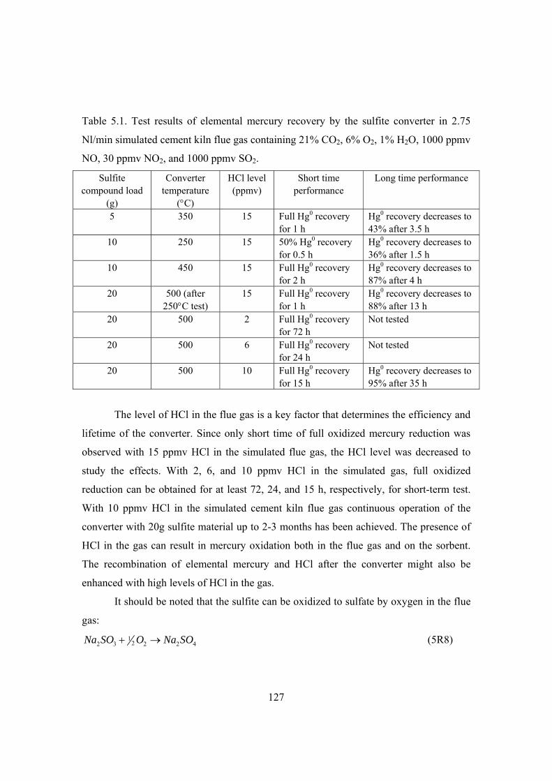
127
Table 5.1. Test results of elemental mercury recovery by the sulfite converter in 2.75
Nl/min simulated cement kiln flue gas containing 21% CO2, 6% O2, 1% H2O, 1000 ppmv
NO, 30 ppmv NO2, and 1000 ppmv SO2.
Sulfite compound load
(g)
Converter temperature
(C)
HCl level (ppmv)
Short time performance
Long time performance
5 350 15 Full Hg0 recovery for 1 h
Hg0 recovery decreases to 43% after 3.5 h
10 250 15 50% Hg0 recovery for 0.5 h
Hg0 recovery decreases to 36% after 1.5 h
10 450 15 Full Hg0 recovery for 2 h
Hg0 recovery decreases to 87% after 4 h
20 500 (after 250C test)
15 Full Hg0 recovery for 1 h
Hg0 recovery decreases to 88% after 13 h
20 500 2 Full Hg0 recovery for 72 h
Not tested
20 500 6 Full Hg0 recovery for 24 h
Not tested
20 500 10 Full Hg0 recovery for 15 h
Hg0 recovery decreases to 95% after 35 h
The level of HCl in the flue gas is a key factor that determines the efficiency and
lifetime of the converter. Since only short time of full oxidized mercury reduction was
observed with 15 ppmv HCl in the simulated flue gas, the HCl level was decreased to
study the effects. With 2, 6, and 10 ppmv HCl in the simulated gas, full oxidized
reduction can be obtained for at least 72, 24, and 15 h, respectively, for short-term test.
With 10 ppmv HCl in the simulated cement kiln flue gas continuous operation of the
converter with 20g sulfite material up to 2-3 months has been achieved. The presence of
HCl in the gas can result in mercury oxidation both in the flue gas and on the sorbent.
The recombination of elemental mercury and HCl after the converter might also be
enhanced with high levels of HCl in the gas.
It should be noted that the sulfite can be oxidized to sulfate by oxygen in the flue
gas:
122 3 2 2 4Na SO O Na SO (5R8)

128
To study the effects of sodium sulfite oxidation to sulfate on oxidized mercury reduction
efficiency, the sulfite pellets were first exposed to 12% O2 at 350C for 18 h. Figure 5.6
shows that the maximum Hg0 recovery is about 90% after preconditioning by oxygen and
slowly decreases with time. This indicates that the sodium sulfite was partly oxidized to
sodium sulfate during preconditioning by oxygen. The formed sulfate is not active for
reduction of oxidized mercury to elemental mercury. Normally the analyzer is running all
the time to avoid damage of the lamp by restarting of the analyzer. When the experiment
is not run, air is added to the analyzer. The test of oxygen precondition indicates that the
converter should be closed to avoid oxidation of the sulfite compound when the
experiment is not running. Instead the analyzer is running in Hg0 measurement mode
with air to the analyzer, bypassing the converter.
0 30 60 90 120
Time (min)
0
40
80
120
160
200
Hg
co
nce
ntr
atio
n (g
/Nm
3 ) Hgtotal bypassreactor Hgtotal through reactor
Hg0 inlet
Figure 5.6. Test of 20 g sodium sulfite converter materials at 350C using 2.75 Nl/min
simulated flue gas with 15 ppmv HCl. The sulfite pellets were pre-conditioned by 12%
O2 for 18 h. Oxidized mercury is produced by passing gases through 4 g SCR catalyst at
150C.

129
The dynamics of the converter were investigated by studying the response time of
mercury measurement to the change of mercury addition and switching between the
reactor and bypass. This was carried out by step up and step down tests [7]. The
dynamics of Hg0 measurement bypassing the converter were first investigated. The steps
of the dynamics test are illustrated in figure 5.7 Air was used as zero gas and added to the
analyzer directly until a stable reading was achieved for about 5 min. Then air addition
was stopped and Hg0 in simulated flue gas was added bypassing the reactor with SCR
catalyst and the sulfite converter to measure the Hg0 inlet level. After a stable reading of
the inlet Hg0 level was obtained for about 10 min, zero air was added to the analyzer and
step down test of Hg0 measurement was finished when stable reading was obtained. The
95% response time of both step up and down is less than 0.5 min for elemental mercury
measurement bypassing the sulfite converter. The step change is very similar to that seen
in the elemental measurement shown in figure 5.2.
0 30 60 90 120
Time (min)
0
20
40
60
80
100
120
140
Hg
co
nce
ntr
atio
n (g
/Nm
3 )
BypassSCR
Air to converter, gas to SCR
ThroughSCR
Air to converter
BypassSCR
BypassSCRstop Hgaddition
Figure 5.7. Response of total mercury measurement with elemental Hg inlet level of 112
g/Nm3. 20 g sodium sulfite converter materials is used in the converter at 500C using
2.75 Nl/min simulated flue gas with 10 ppmv HCl. Oxidized mercury is produced by
passing gases through 4 g SCR catalyst at 150C.

130
Then the measurement was switched to total mercury measurement through the
converter. The Hg0 in the simulated flue gas was added to the reactor with SCR catalyst
and the converter. The step up test of total mercury measurement was finished when
stable mercury measurement through the converter was achieved for 50 min. Then air
was added to the converter for a step down test. The dynamic tests were conducted at
different Hg0 inlet levels of 41, 112, and 150 µg/Nm3. Figure 5.7 shows the response of
both Hg0 measurement bypassing the converter and SCR catalyst and total mercury
measurement through the SCR catalyst and converter with a Hg0 inlet level of 112
µg/Nm3. Close look at the response for step change in figure 5.8 shows that the response
of mercury measurement is very fast for both step up and down tests. The 95% response
time for step up and down change is 1.5 and 0.6 min, respectively.
34 36 38 40 42 44 46 48 50
Time (min)
0
20
40
60
80
100
120
Hg
co
nce
ntr
atio
n (g
/Nm
3)
78 80 82 84 86
Time (min)
95% step down change
95% step up change
0.60 min1.50 min
Figure 5.8. Close look of the response time test shown in figure 5.7. Left: step up test by
switching gas addition to the sulfite converter from air to simulated flue gas with
oxidized mercury produced by SCR catalyst. Right: step down test by switching gas
addition to the sulfite converter from simulated flue gas with oxidized mercury produced
by SCR catalyst to air.

131
5.5 Examples of dynamic measurement of mercury adsorption and
oxidation on activated carbon
Commercial activated carbons, Darco Hg and HOK standard were investigated in
simulated cement kiln flue gas at 150C. Figure 5.9 shows the mercury profiles for the
Darco Hg activated carbon. The experiments are conducted twice using separate total and
elemental mercury measurement. Comparison of the elemental and total mercury
measurement shows that both adsorption and oxidation of mercury by the carbon occur.
After mercury breakthrough is achieved, the mercury oxidation is stable at about 92%.
0 0.5 1 1.5 2 2.5 3 3.5
Time (hour)
0
40
80
120
160
200
Gas
eou
s H
g (g
/Nm
3 )
Gaseous Hgtotal
Gaseous Hg0
bypassreactor
throughreactor
Figure 5.9. Total and elemental mercury profile of 30 mg Darco Hg activated carbon
mixed with 2 g sand at 150C using 2.75 Nl/min simulated cement kiln flue gas with 10
ppmv HCl, two separate tests and measurements.
Rather than running the test of the same carbon twice as shown in figure 5.9, it is
possible to run the test once and evaluate both the mercury adsorption and oxidation by
the carbon. The mercury breakthrough was first obtained by measuring total mercury
through the converter, then zero air is added to the converter and the analyzer was
changed to Hg0 measurement mode. During this period mercury in simulated gas was
still added to the sorbent to avoid possible desorption of mercury from the carbon. When

132
the analyzer was running for Hg0 measurement, gases after the reactor were switched to
the analyzer to measure Hg0. Figure 5.10 illustrates the mercury adsorption and oxidation
by HOK standard carbon at 150C. In this case 57% mercury oxidation was observed.
Both the tests of Darco Hg and HOK in simulated cement kiln flue gas show that the
sulfite converter and analysis system are capable of following the transient mercury
outlet concentration in a satisfactory way.
0 1 2 3 4 5
Time (min)
0
40
80
120
160
200
Gas
eou
s H
g (g
/Nm
3 )
bypassreactorHgtotal
through reactor Hgtotal
Gas to reactor, air to analyzerchange from Hgtotal to Hg0 measurement
through reactor Hg0
Figure 5.10. Total and elemental mercury profile of 30 mg HOK standard activated
carbon mixed with 2 g sand at 150C using 2.75 Nl/min simulated cement kiln flue gas
with 10 ppmv HCl.
5.6 Suggestions for practical application of the converter
The conditions in full-scale application are much more demanding than in the lab-
scale investigation. In this work no particles in the gas stream were applied. On the other
hand, the dust load in the flue gas between the raw mill and filter could be up to 800-
1000 g/Nm3. The sampling probe needs to be able to separate the particles from the flue
gas efficiently to avoid plugging of probe. Adsorption of mercury by the dust and probe
should be minimized by high sampling flow rate and high filter temperature.

133
The HCl content in the cement kiln flue gas can be up to 20-25 ppmv [24]. As
found in this work, the full Hg0 recovery can only be maintained for short period when
more than 10 ppmv HCl is present in the flue gas. It is therefore necessary to remove HCl
before or in the converter. Lime pellets can be used together with the sulfite compounds
and the converter temperature should be high enough to avoid mercury adsorption on the
lime pellets. Alternatively, large amount of converter material might be used.
Compared to power plants and incinerators, the emission levels of CO and
volatile organic compounds such as hydrocarbons are higher in cement plants. The
emission level of volatile organic compound in the stack gas of cement kilns is usually
between 10 and 100 mg/Nm3, with a few excessive cases up to 500 mg/Nm3[25]. The CO
concentration in the stack gas can be as high as 1000 mg/Nm3, even exceeding 2000
mg/Nm3 in some cases. High levels of CO and hydrocarbons in the flue gas will cause
fast contamination of the windows in the analytical cells and interruption of the mercury
measurement [22]. Measures such as dilution should be applied to minimize the problem.
The sulfite material should be kept in a closed box to avoid oxidation by air and
moisture. It is important that the sulfite powders are adhered uniformly to the surface of
the thin layer of water glass on the zeolite pellets. Thoroughly mixing the water glass
with zeolite pellets in a plastic container can improve the sulfite converter performance.
In this way, the sulfite converter can work well up to months, as observed in this work.
For both lab-scale and full-scale application of the analysis system, it is important
to avoid cold parts in the system. All the connections, Teflon lines and gas contacting
parts in the analyzer before the spectrometry should be heated above 150C. When the
converter is not used, the converter temperature should be decreased to 100C. The
converter should be closed to avoid deactivation of the converter material due to
oxidation of sulfite to sulphate by air.
5.7 Conclusions
To be able to perform dynamic measurement of mercury adsorption by sorbents,
red brass chips and sulfite converter were investigated in simulated cement kiln flue gas

134
in a fixed-bed reactor system. The converter with red brass chips works only when
measuring elemental mercury in nitrogen (i.e., without carrying out actual conversion)
and does not work properly even when only elemental mercury was added to the
simulated flue gas. The red brass is poisoned or oxidized within a short time and adsorbs
elemental mercury. When oxidized mercury was produced by passing gases through a
separate reactor with an SCR catalyst, the red brass converter cannot fully reduce HgCl2
to elemental mercury under any relevant condition.
Sodium sulfite converter material was prepared by dry impregnation of sodium
sulfite and calcium sulfate powders on zeolite pellets using water glass as binder. The
optimal operating temperature of the sulfite converter is 500C. The level of HCl in the
flue gas is a key factor that determines the efficiency and lifetime of the converter. Full
elemental mercury recovery can only be obtained for short period with 15 ppmv HCl in
the simulated gas, but the sulfite converter works well at 500C with up to 10 ppmv HCl
in the simulated cement kiln flue gas. When the converter is not used, the converter
temperature was decreased to 100C without air passing through to avoid deactivation of
the converter material by oxidation of the sodium sulfite to sodium sulfate. The response
time of the sulfite converter is short and typically within at most two minutes, which
makes it appropriate for not too fast dynamic measurements, as verified by dynamic
mercury adsorption tests on commercial activated carbons Darco Hg and HOK standard
in a fixed-bed reactor. Suggestions for practical application of the sulfite converter in
cement plant with high dust load are provided.
5.8 References
[1] R.J. Schreiber and C.D. Kellett, Compilation of mercury emissions data, PCA R&D Serial No.
SN3091, 2009.
[2] D.L. Laudal, J.S. Thompson, J.H. Pavlish, L.A. Brickett, P. Chu, Use of continuous mercury
monitors at coal-fired utilities, Fuel Processing Technology. 85 (2004) 501-511.
[3] J. Wu, Y. Du and W. Pan, J. Ren, P. He, W. Wang, M. Shen, X. Leng, Y. Jin, Z. Dai, L. Zhao,
X. Ming, Y. Cao, W. Pan, Study on different measurement methods of mercury emission in the

135
coal-fired power station, 3rd International Conference on Bioinformatics and Biomedical
Engineering, Beijing, China, June 11-13, 2009.
[4] V. Schmid, Continuous monitoring of mercury emissions from stationary sources, 2002.
[5] M. Holmes and J. Pavlish, Mercury information of clearinghouse, Quarterly 2–mercury
measurement, 2004.
[6] J. Wang, Z. Xiao, O. Lindqvist, On-line measurement of mercury in simulated flue gas, Water,
Air, & Soil Pollution. 80 (1995) 1217-1226.
[7] M.L. Jones, D.L. Laudal and J.H. Pavlish, Mercury emission monitoring for the cement
industry, Cement Industry Technical Conference Record, 2008 IEEE, Miami, Florida, May 18-22,
2008.
[8] Wikipedia, Brass, http://en.wikipedia.org/wiki/Brass, accessed December 7, 2010.
[9] R. Kanefke, H. Köser, B. Vosteen, F. Kristina, B. Frank, S. Raik, Method for the production
of elemental mercury from mercury compounds, patent WO 2008/064667 A2, 2008.
[10] J.A. Rodriguez, T. Jirsak, J. Dvorak, S. Sambasivan, D. Fischer, Reaction of NO2 with Zn
and ZnO: Photoemission, XANES, and density functional studies on the formation of NO3, The
Journal of Physical Chemistry B. 104 (2000) 319-328.
[11] S. Lee, J. Lee, T.C. Keener, Bench-scale studies of in-duct mercury capture using cupric
chloride-impregnated carbons, Environ. Sci. Technol. 43 (2009) 2957-2962.
[12] S. Lee, J. Lee, T.C. Keener, The effect of methods of preparation on the performance of
cupric chloride-impregnated sorbents for the removal of mercury from flue gases, Fuel. 88 (2009)
2053-2056.
[13] A. Makkuni, R.S. Varma, S.K. Sikdar, D. Bhattacharyya, Vapor phase mercury sorption by
organic sulfide modified bimetallic iron-copper nanoparticle aggregates, Ind Eng Chem Res. 46
(2007) 1305-1315.
[14] D.E. Meyer, S.K. Sikdar, N.D. Hutson, D. Bhattacharyya, Examination of sulfur-
functionalized, copper-doped iron nanoparticles for vapor-phase mercury capture in entrained-
flow and fixed-bed systems, Energy & Fuels. 21 (2007) 2688-2697.
[15] D.E. Meyer, N. Meeks, S. Sikdar, N.D. Hutson, D. Hua, D. Bhattacharyya, Copper-doped
silica materials silanized with bis-(triethoxy silyl propyl)-tetra sulfide for mercury vapor capture,
Energy Fuels. 22 (2008) 2290-2298.
[16] D.L. Laudal, J.S. Thompson, J.H. Pavlish, L. Brickett, P. Chu, R.K. Srivastava, J. Kilgroe,
C.W. Lee, Mercury speciation at power plants using SCR and SNCR control technologies, EM:
Air and Waste Management Association's Magazine for Environmental Managers. (2003) 16-22.
[17] H.G. Pedersen, L.S. Pedersen, H. Rostgaard and K. Pedersen, Oxidation of mercury on DNX
catalysts. Proceedings of the Air Quality V: Mercury, Trace Elements, SO3, and Particulate
Matter Conference, Arlington, VA, Sept 19–21, 2005.

136
[18] S. Straube, T. Hahn, H. Koeser, Adsorption and oxidation of mercury in tail-end SCR-
DeNOx plants—Bench scale investigations and speciation experiments, Applied Catalysis B:
Environmental. 79 (2008) 286-295.
[19] Y. Zhuang, J. Laumb, R. Liggett, M. Holmes, J. Pavlish, Impacts of acid gases on mercury
oxidation across SCR catalyst, Fuel Processing Technology. 88 (2007) 929-934.
[20] Y. Cao, Z. Gao, J. Zhu, Q. Wang, Y. Huang, C. Chiu, B. Parker, P. Chu, W. Pan, Impacts of
halogen additions on mercury oxidation in a slipstream selective catalyst reduction (SCR) reactor
when burning sub-bituminous coal, Environ. Sci. Technol. 42 (2008) 256-261.
[21] H. Kamata, S. Ueno, T. Naito, A. Yukimura, Mercury oxidation over the V2O5(WO3)/TiO2
commercial SCR catalyst, Ind Eng Chem Res. 47 (2008) 8136-8141.
[22] R. Moeseler. Issues about red brass converter, personal communication, Lumex Analytical
GmbH, 2010.
[23] S. Akiyama, J. Kato, F. Koga, K. Ishikawa, Catalysts for reducing mercury, a mercury
conversion unit, and an apparatus for measuring total mercury in combustion exhaust gas by
using the same, patent US2007/0232488 A1, 2007.
[24] C. Senior, A. Sarofim and E. Eddings, Behavor and measurement of mercury in cement
kilns, presented at the IEE-IAS/PCA 45th Cement Industry Technical Conference, Dallas, Texas,
May 4-9 2003.
[25] CEMBUREAU, the European Cement association, Best available technologies for the
cement industry, 1999.
137
6
Effects of bed dilution and carbon load on
mercury adsorption capacity of activated
carbon
This chapter reports the effects of bed dilution and carbon load on the equilibrium
mercury adsorption capacity of the activated carbon. The mercury adsorption capacity
per unit mass of the activated carbon decreases when the carbon load is increased.
Detailed investigations are conducted to reveal the cause.
6.1 Introduction
Most of the studies on mercury adsorption use bed dilution [1-9], while only few
investigations apply pure sorbent bed [10-14] when the mercury sorbents are evaluated in
fixed-bed reactors. The sorbent beds are often diluted with inert particles to suppress
other potential disturbing effects such as axial dispersion and bypassing [15,16]. Low-
surface-area materials such as glass beads and sand/quartz powder are preferred as
diluting solids because of their relative inertness and good heat transfer properties. The
effects of sorbent load on the mercury adsorption capacity of the sorbent are rarely
reported in the literature.
6.2 Effects of carbon load
The direct result of the fixed-bed test is the mercury adsorption breakthrough
curve. The percentage breakthrough is determined as a function of time by normalizing
the measured total mercury concentration at the outlet of the sorbent bed to the inlet
mercury concentration.
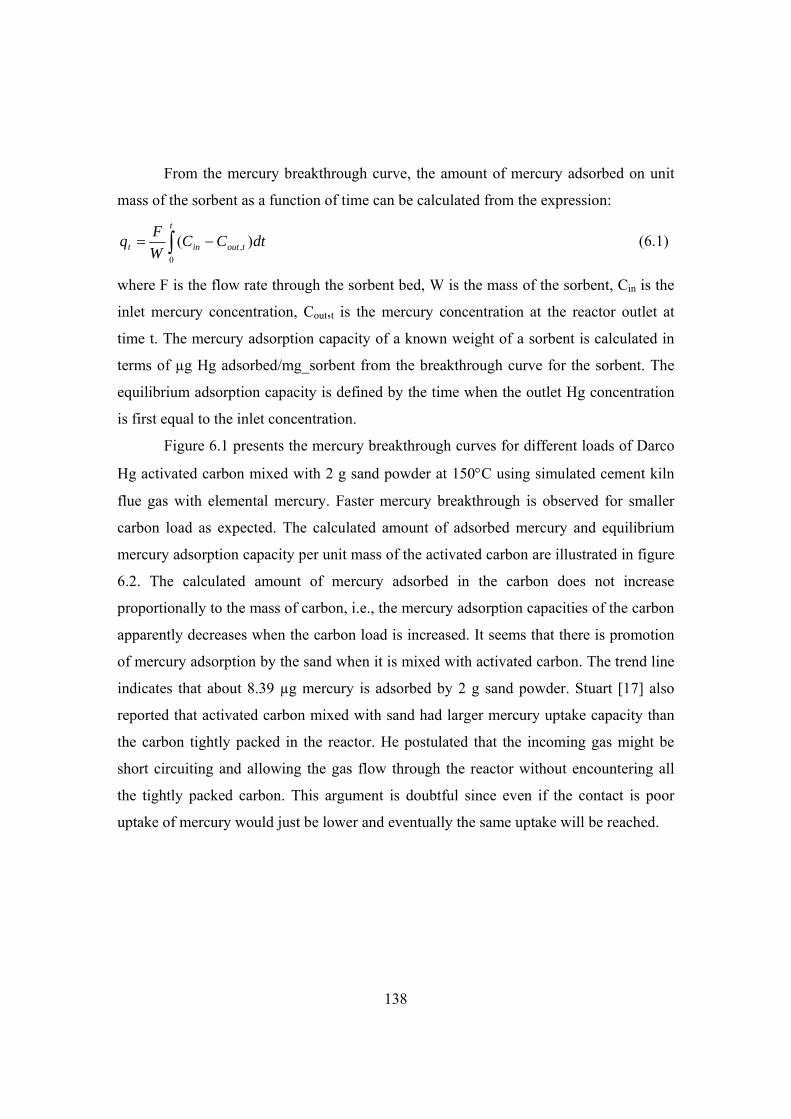
138
From the mercury breakthrough curve, the amount of mercury adsorbed on unit
mass of the sorbent as a function of time can be calculated from the expression:
t
toutint dtCCW
Fq
0
, )( (6.1)
where F is the flow rate through the sorbent bed, W is the mass of the sorbent, Cin is the
inlet mercury concentration, Cout,t is the mercury concentration at the reactor outlet at
time t. The mercury adsorption capacity of a known weight of a sorbent is calculated in
terms of µg Hg adsorbed/mg_sorbent from the breakthrough curve for the sorbent. The
equilibrium adsorption capacity is defined by the time when the outlet Hg concentration
is first equal to the inlet concentration.
Figure 6.1 presents the mercury breakthrough curves for different loads of Darco
Hg activated carbon mixed with 2 g sand powder at 150C using simulated cement kiln
flue gas with elemental mercury. Faster mercury breakthrough is observed for smaller
carbon load as expected. The calculated amount of adsorbed mercury and equilibrium
mercury adsorption capacity per unit mass of the activated carbon are illustrated in figure
6.2. The calculated amount of mercury adsorbed in the carbon does not increase
proportionally to the mass of carbon, i.e., the mercury adsorption capacities of the carbon
apparently decreases when the carbon load is increased. It seems that there is promotion
of mercury adsorption by the sand when it is mixed with activated carbon. The trend line
indicates that about 8.39 µg mercury is adsorbed by 2 g sand powder. Stuart [17] also
reported that activated carbon mixed with sand had larger mercury uptake capacity than
the carbon tightly packed in the reactor. He postulated that the incoming gas might be
short circuiting and allowing the gas flow through the reactor without encountering all
the tightly packed carbon. This argument is doubtful since even if the contact is poor
uptake of mercury would just be lower and eventually the same uptake will be reached.

139
0 1 2 3 4 5 6
Time (hour)
0
0.2
0.4
0.6
0.8
1
1.2
Co
ut/C
in
A B C D
A: 10 mgB: 30 mgC: 60 mgD: 100 mg
Figure 6.1. Mercury breakthrough curves of different Darco Hg activated carbon loads
mixed with 2 g sand powder and tested at 150C using 2.75 Nl/min simulated flue gas
with 170 µg/Nm3 elemental mercury, 1000 ppmv NO, 23 ppmv NO2, 1000 ppmv SO2, 10
ppmv HCl, 1 vol.% H2O, 6 vol.% O2, and 21 vol.% CO2.
0 20 40 60 80 100 120
Carbon load in 2 g sand (mg)
0
10
20
30
40
50
Ad
sorb
ed H
g (g
)
0
0.2
0.4
0.6
0.8
1
1.2H
g A
dso
rpti
on
cap
acit
y (
g H
g/m
g_c
arb
on
)
Adsorbed Hg
Adsorbed HgY=0.3797X+8.3921,R2=0.99Adsorption capacity
Figure 6.2. Calculated amount of adsorbed mercury and equilibrium mercury adsorption
capacity of Darco Hg activated carbon mixed with 2 g sand powder and tested at 150C
with different carbon loads using 2.75 Nl/min simulated flue gas with 170 µg/Nm3
elemental mercury, 1000 ppmv NO, 23 ppmv NO2, 1000 ppmv SO2, 10 ppmv HCl, 1
vol.% H2O, 6 vol.% O2, and 21 vol.% CO2.

140
To investigate whether the oxidation of elemental mercury could influence the
mercury adsorption capacity, mercury adsorption by different carbon loads using HgCl2
source are conducted. As shown in figure 6.3, similar trends as tests with elemental
mercury source are observed. This implies that the decrease of mercury adsorption
capacity with increased carbon load in the sand is not caused by the oxidation of
elemental mercury.
0 10 20 30 40 50 60 70 80
Carbon load (mg)
0
5
10
15
20
25
30
35
Ad
sorb
ed m
ercu
ry (g
)
0
0.2
0.4
0.6
0.8
1
1.2
1.4
1.6
1.8
2
Hg
ad
sorp
tio
n c
apac
ity
(g
Hg
/mg
_ca
rbo
n)
Adsorbed HgAdsorbed Hg Y=0.426X+6.739,R2=0.96Adsorption capacity
Figure 6.3. Calculated amount of adsorbed mercury and equilibrium mercury adsorption
capacity of Darco Hg activated carbon mixed with 2 g sand powder and tested at 150C
with different carbon loads using 2.75 Nl/min simulated flue gas with 170 µg/Nm3
mercury from HgCl2 source, 1000 ppmv NO, 23 ppmv NO2, 1000 ppmv SO2, 10 ppmv
HCl, 1 vol.% H2O, 6 vol.% O2, and 21 vol.% CO2.
One possible cause of the decrease of mercury adsorption capacity with increased
carbon load could be the wall effect. Carbon particles separate from sand powders during
loading the sample to the reactor. A layer of carbon particles deposits on the sample
holder. Later these carbon particles are loaded to the reactor by knocking the sample
holder. During loading of the sample to the reactor, carbon particles stick on the reactor
wall. A quartz wool plug is used to move the carbon particles that adhere on the reactor
wall to the top of the carbon bed. As a result some carbon particles are loaded to the area

141
close to the reactor wall. More carbon particles adhere on the reactor wall when larger
carbon load is applied.
Another reason might be the leakage of the system and mercury adsorption by the
quartz wool and sand powder. However, leakage tests of the system at different stages of
the project show that the system is tight. The pressure drop over the carbon bed is about 5
mbar. The deviation of the flow rates at the reactor inlet and outlet to the flow rate after
the gas mixing panel is within 2.2%. Tests with empty reactor, reactor with quartz wool,
and sand powder do not show any adsorption of either elemental mercury or mercury
chloride.
6.3 Effects of bed dilution
Negative deviation of conversion caused by dilution of the catalyst bed with inert
particles in gas-solid systems has been reported [15,16]. Dilution of activated carbon by
inert sand powder is applied in this work; it is therefore relevant to evaluate the possible
effects caused by the dilution. The extent of negative effect depends on the amount of
dilution, the reaction/adsorption kinetics, the particles and reactor geometry, and the
degree of segregation of carbon and sand. Since the mercury removal fraction by the
carbon bed changes with time, the dilution effect as a relative measure of the deviation
in the conversion can be calculated for different time:
( ) ( )( ) undiluted diluted
undiluted
x t x tt
x
(6.2)
where xdiulted(t) and xundiluted(t) is the mercury removal fraction at time t for diluted and
undiluted bed, respectively.
For practical application the relative deviation in conversion can be estimated
from observable parameters [15,16] :
( )( ) ( )
1 2p diluted
bed
d x tbt
b h
(6.3)
where b is the volume of inert sand as fraction of total volume of solids, dp is carbon
particle diameter, and hbed is the bed height.
For 10 mg Darco Hg carbon mixed with 2 g sand, the b is calculated as:

142
3
6 3
/ 2 10 /16020.98
/ / 10 10 / 510 2 10 /1602sand sand
carbon carbon sand sand
mb
m m
Figure 6.4 presents the calculated relative deviation in mercury adsorption as a
function of time for different loads of Darco Hg carbon tested at 180C in simulated
cement kiln flue gas. Larger relative deviation in short period is observed for smaller
carbon loads, i.e., larger dilution ratio. However, the area under the relative deviation
curve and above the zero deviation appears to be similar for different carbon loads. This
indicates that the influence of bed dilution on the equilibrium mercury adsorption
capacity of the carbon is similar. Therefore the decrease of mercury adsorption capacity
with increase of carbon loads is probably not caused by the bed dilution.
0 0.5 1 1.5 2 2.5
Time (hour)
-0.01
0
0.01
0.02
0.03
0.04
0.05
0.06
0.07
0.08
Rel
ativ
e d
evia
tio
n,
A
B
C
A: 10 mg carbon, b=0.98B: 30 mg carbon, b=0.96C: 60 mg carbon, b=0.91
Figure 6.4. The calculated relative deviation as a function of time for tests at 180C
with different carbon loads using 2.75 Nl/min simulated flue gas with 170 µg/Nm3
mercury from HgCl2, 1000 ppmv NO, 23 ppmv NO2, 1000 ppmv SO2, 10 ppmv HCl, 1
vol.% H2O, 6 vol.% O2, and 21 vol.% CO2.
Tests using same dilution ratio, i.e., 10 mg carbon is mixed with 2 g sand, 30 mg
carbon with 6 g sand, 60 mg carbon with 12 g sand, are also performed at 180C using
simulated cement kiln flue gas with HgCl2. Figure 6.5 shows the calculated amount of
adsorbed mercury and equilibrium mercury adsorption capacity of the activated carbon.

143
Similar mercury adsorption capacity is still not obtained for different carbon loads, which
behaves as with 2 g sand.
0 10 20 30 40 50 60 70 80
Carbon load (mg)
0
5
10
15
20
25
30
Ad
sorb
ed m
ercu
ry (g
)
0
0.2
0.4
0.6
0.8
1
Hg
ad
sorp
tio
n c
ap
acit
y (
g H
g/m
g_c
arb
on
)
Adsorbed HgAdsorbed HgY=0.3777X+7.0386,R2=0.97Adsorption capacity
Figure 6.5. Calculated amount of adsorbed mercury and equilibrium mercury adsorption
capacity of Darco Hg activated carbon mixed with sand powder using same dilution rate
and tested at 180C with different carbon loads using 2.75 Nl/min simulated flue gas
with 170 µg/Nm3 mercury from HgCl2 source, 1000 ppmv NO, 23 ppmv NO2, 1000
ppmv SO2, 10 ppmv HCl, 1 vol.% H2O, 6 vol.% O2, and 21 vol.% CO2.
6.4 Effects of sand load
If the mercury adsorption by activated carbon is promoted by the sand mixing, it
would be interesting to investigate the effects of sand load on the promotion of mercury
adsorption capacity of the carbon by running tests with different masses of sand. Table
6.2 presents the calculated amount of adsorbed mercury and equilibrium mercury
adsorption capacity of 10 mg Darco Hg activated carbon mixed with different amounts of
sand powder at 150C in simulated cement kiln flue gas with HgCl2. When the sand load
is above 20 mg the mercury adsorption capacities of the Darco Hg do not increase further
and level off at a value of about 1.135 µg Hg/mg_carbon. This also indicates that the
repeatability of the experiment is reasonable.

144
Table 6.2. Calculated amount of adsorbed mercury and equilibrium mercury adsorption
capacity of 10 mg Darco Hg activated carbon mixed with different amounts of sand
powder and tested at 150C using 2.75 Nl/min simulated flue gas with HgCl2 source,
1000 ppmv NO, 23 ppmv NO2, 1000 ppmv SO2, 10 ppmv HCl, 1 vol.% H2O, 6 vol.% O2,
and 21 vol.% CO2.
Sand load (g) Hg inlet (µg/Nm3) Adsorbed Hg (µg) Adsorption capacity (µg Hg/mg_carbon)
0 164 5.06 0.506 0.01 161 9.81 0.981 0.02 160 11.36 1.136 0.05 166 11.48 1.148 0.10 164 11.07 1.107 0.25 166 12.17 1.217 0.5 174 10.50 1.050 1 217 10.24 1.024 2 183 12.24 1.224 2 163 11.80 1.180 4 206 11.29 1.129
6.5 Effects of carbon loading location
The carbon sample was separated from the sand powder with quartz wool plug to
test possible effect of carbon loading location. Different locations of the carbon sample
are applied to investigate whether the promotion of mercury adsorption is caused by the
preconditioning of the gas by the sand. When the carbon is on top of the sand, the flue
gas first contacts the carbon powder. However, as shown in figure 6.6, the equilibrium
mercury adsorption capacity is almost the same when the carbon sample is loaded on top
of and under the sand powder. This implies that the promotion of mercury adsorption
only occurs when the carbon is mixed with sand powder. The slightly larger mercury
adsorption capacity with sand powder in the reactor compared to only carbon in the
reactor might be due to the improved contact of carbon with gas flow.

145
0
0.1
0.2
0.3
0.4
0.5
0.6
0.7
Hg
ad
sorp
tio
n c
apac
ity
(g
Hg
/mg
-ca
rbo
n)
No
san
d
Car
bo
n o
n t
op
San
d o
n t
op
Figure 6.6. Equilibrium mercury adsorption capacity of 10 mg Darco Hg activated
carbon on top of and under 1 g sand powder at 150C using 2.75 Nl/min simulated flue
gas with 170 µg/Nm3 mercury from HgCl2 source, 1000 ppmv NO, 23 ppmv NO2, 1000
ppmv SO2, 10 ppmv HCl, 1 vol.% H2O, 6 vol.% O2, and 21 vol.% CO2.
6.6 Effects of bed materials
Different bed materials are applied to investigate the possible effects of bed
materials on the mercury adsorption capacity of activated carbon. The investigated bed
materials include sand powder, fine quartz powder, and glass beads and the mean
diameters of these materials are 215, 2, and 180 µm, respectively. Baseline tests with
only fine quartz powder and glass beads show that fine quartz powder is inert for
mercury adsorption and the mercury adsorption by the glass beads is negligible. Figure
6.7 compares the mercury adsorption capacity of Darco Hg activated carbon tested with
different bed materials. The mercury adsorption capacity of Darco Hg carbon tested with
fine quartz powder is much smaller than those with sand powder and glass beads. The
fine quartz powder behaves like paste and might hinder the contact of gas with the
carbon particles. Inconsistent mercury adsorption capacity is still obtained when different
amounts of carbon are mixed with 2 g sand powder, fine quartz powder, and glass beads.

146
0
0.2
0.4
0.6
0.8
1
1.2
1.4
Hg
ad
sorp
tio
n c
ap
aity
(g
Hg
/mg
_c
arb
on
)
10 mg carbon in 2 g bed material
30 mg carbon in 2 g bed material
San
d p
ow
der
Fin
e q
uar
tz p
ow
der
Gla
ss b
ead
s
San
d p
ow
der
Fin
e q
uar
tz p
ow
de
r
Gla
ss b
ead
s
Figure 6.7. Equilibrium mercury adsorption capacity of Darco Hg activated carbon
mixed with different bed materials and tested at 150C using 2.75 Nl/min simulated flue
gas with 170 µg/Nm3 mercury from HgCl2 source, 1000 ppmv NO, 23 ppmv NO2, 1000
ppmv SO2, 10 ppmv HCl, 1 vol.% H2O, 6 vol.% O2, and 21 vol.% CO2.
6.7 Effects of carbon type and particle size
To study the effects of carbon type and particle size on the mercury adsorption
capacity, commercial activated carbon pellets of Norit RB4 are crushed and sieved to
size of 165 and less than 32 µm in diameter. Figure 6.8 shows the mercury adsorption
capacity obtained with different carbon loads, carbon types and particle size. Inconsistent
mercury adsorption capacity at different carbon loads is observed for both Darco Hg and
Norit RB4 carbons with different sizes. The effects of carbon load are much smaller for
Norit RB4 carbon.

147
0 10 20 30 40 50 60 70 80
Carbon load (mg)
Darco Hg, 16 m
Norit RB 4, 165 m
Norit RB 4, <32 m
0
0.2
0.4
0.6
0.8
1
1.2
1.4
1.6
1.8
2
Hg
ad
sorp
tio
n c
apac
ity
(g
Hg
/mg
_car
bo
n)
Figure 6.8. Equilibrium mercury adsorption capacity as a function of carbon loads for
Darco Hg activated carbon and Norit RB4 with different sizes mixed with 2 g sand
powder and tested at 150C using 2.75 Nl/min simulated flue gas with 170 µg/Nm3
mercury from HgCl2 source, 1000 ppmv NO, 23 ppmv NO2, 1000 ppmv SO2, 10 ppmv
HCl, 1 vol.% H2O, 6 vol.% O2, and 21 vol.% CO2. 6.8 Tests with only Portland cement
Instead of using sorbent and sand mixture, 1-4 g Portland cement is tested at
150C with HgCl2 in the simulated cement kiln flue gas. Figure 6.9 shows that the
adsorbed mercury is proportional to the cement load and the equilibrium mercury
adsorption capacity of the cement is similar for different cement loads.

148
1 2 3 4 5
Portland cement load (g)
2
3
4
5
6
7
8
9
10
Ad
sorb
ed H
g (g
)
0
0.0005
0.001
0.0015
0.002
0.0025
Hg
ad
sorp
tio
n c
apac
ity
(g
Hg
/mg
_cem
ent)
Adsorbed HgAdsorption capacity
Figure 6.9. Calculated amount of adsorbed mercury and equilibrium mercury adsorption
capacity as a function of Portland cement load at 150C using 2.75 Nl/min simulated flue
gas with 170 µg/Nm3 mercury from HgCl2 source, 1000 ppmv NO, 23 ppmv NO2, 1000
ppmv SO2, 10 ppmv HCl, 1 vol.% H2O, 6 vol.% O2, and 21 vol.% CO2. 6.9 Conclusions
Inconsistent mercury adsorption capacity of activated carbon is observed at
different carbon loads when mixed with sand. Smaller mercury adsorption capacity is
obtained with larger carbon load. Tests with elemental mercury and mercury chloride,
different carbon type and particle sizes show the same trend. Effects of bed dilution at
fixed carbon load on the equilibrium mercury adsorption capacity appear to be limited.
The mercury adsorption capacity of activated carbon obtained using sand and
carbon mixture is larger than that obtained with only activated carbon. The mercury
adsorption capacity with 10 mg carbon increases with sand load up to 20 mg and then
levels off when the sand load is further increased.
Similar mercury adsorption capacities are obtained with different Portland cement
loads in the reactor. This implies that the inconsistent mercury adsorption capacity of
carbon obtained using different carbon loads might be due to possible adsorption of

149
mercury by sand when it is mixed with carbon, rather than the failure of the experimental
setup. The sand powder alone is inert for mercury adsorption, while after modification
with chemical reagent it can be used for mercury adsorption [18,19]. In-situ analysis
technology is required to reveal whether mercury is adsorbed by the sand when it is
mixed with activated carbon.
The problem of inconsistent mercury adsorption capacity was encountered in the
late stage of the project when performing a fundamental parametric study. Although
detailed tests are conducted to reveal the cause, the problem is not solved due to the lack
of analysis techniques and time. It is impossible to repeat and run all the tests with only
large carbon load within the time schedule of the project. For a full-scale application in
the cement plant it is impossible to exclude all the cement materials in the flue gas even
with a polishing filter. Instead of providing actual kinetics data relevant to full-scale
application conditions, this work aims at evaluation the effects of different operating
parameters and mathematical model development. Therefore, mercury adsorption
kinetics obtained using 10 mg activated carbon mixed with 2 g sand powder is used in
the following chapters dealing with parametric study and model development. It may be
argued that it is difficult to state what the real capacity is if it depends on the mixing
condition. In reality there will always be least 20 mg diluter with the sorbent and this is
where it has stabilized.
6.10 References
[1] S. Sjostrom, T. Ebner, T. Ley, R. Slye, C. Richardson, T. Machalek, M. Richardson, R.
Chang, Assessing sorbents for mercury control in coal-combustion flue gas, J. Air & Waste
Manage. Assoc. 52 (2002) 902.
[2] S.J. Lee, Y. Seo, J. Jurng, T.G. Lee, Removal of gas-phase elemental mercury by iodine- and
chlorine-impregnated activated carbons, Atmospheric Environment. 38 (2004) 4887-4893.
[3] D. Karatza, A. Lancia, D. Musmarra, Fly ash capture of mercuric chloride vapors from
exhaust combustion gas, Environ. Sci. Technol. 32 (1998) 3999-4004.
[4] J.W. Portzer, J.R. Albritton, C.C. Allen, R.P. Gupta, Development of novel sorbents for
mercury control at elevated temperatures in coal-derived syngas: results of initial screening of
candidate materials, Fuel Processing Technology. 85 (2004) 621-630.

150
[5] J.Y. Lee, Y. Ju, T.C. Keener, R.S. Varma, Development of cost-effective noncarbon sorbents
for Hg0 removal from coal-fired power plants, Environ. Sci. Technol. 40 (2006) 2714-2720.
[6] D. Karata, A. Lancia, D. Musmarra, F. Pepe, Adsorption of metallic mercury on activated
carbon, Symposium (International) on Combustion,. 26 (1996) 2439-2445.
[7] G. Skodras, I. Diamantopoulou, G. Pantoleontos, G.P. Sakellaropoulos, Kinetic studies of
elemental mercury adsorption in activated carbon fixed bed reactor, Journal of Hazardous
Materials. 158 (2008) 1-13.
[8] D. Karatza, A. Lancia, D. Musmarra, C. Zucchini, Study of mercury absorption and
desorption on sulfur impregnated carbon, Experimental Thermal and Fluid Science. 21 (2000)
150-155.
[9] T.R. Carey, O.W. Hargrove Jr, C.F. Richardson, R. Chang, F.B. Meserole, Factors affecting
mercury control in utility flue gas using activated carbon, Journal of the Air & Waste
Management Association. 48 (1998) 1166.
[10] R. Yan, Y.L. Ng, D.T. Liang, C.S. Lim, J.H. Tay, Bench-scale experimental study on the
effect of flue gas composition on mercury removal by activated carbon adsorption, Energy &
Fuels. 17 (2003) 1528-1535.
[11] R. Yan, D.T. Liang, L. Tsen, Y.P. Wong, Y.K. Lee, Bench-scale experimental evaluation of
carbon performance on mercury vapour adsorption, Fuel. 83 (2004) 2401-2409.
[12] G.E. Dunham, R.A. DeWall, C.L. Senior, Fixed-bed studies of the interactions between
mercury and coal combustion fly ash, Fuel Processing Technology. 82 (2003) 197-213.
[13] B.A.F. Mibeck, E.S. Olson, S.J. Miller, HgCl2 sorption on lignite activated carbon: Analysis
of fixed-bed results, Fuel Process Technol. 90 (2009) 1364-1371.
[14] G.E. Dunham, S.J. Miller, Mercury capture by an activated carbon in a fixed-bed bench-
scale system, Environmental Progress. 17 (1998) 203.
[15] R.J. Berger, J. Pérez-Ramírez, F. Kapteijn, J.A. Moulijn, Catalyst performance testing: the
influence of catalyst bed dilution on the conversion observed, Chem. Eng. J. 90 (2002) 173-183.
[16] R.J. Berger, J. Pérez-Ramírez, F. Kapteijn, J.A. Moulijn, Catalyst performance testing: bed
dilution revisited, Chemical Engineering Science. 57 (2002) 4921-4932.
[17] J.L. Stuart. Development of an experimental system to study mercury uptake by activated
carbon under simulated flue gas conditions, Master thesis, University of Pittsburgh, 2002.
[18] M. Holmes and J. Pavlish, Mercury information clearinghouse, Quarter 3- Advanced and
developmental mercury control technologies, July 2004.
[19] J.R. Butz, T.E. Broderick and C.S. Turchi, Amended Silicates™ for Mercury Control,
project final report, DOE Award Number: DE-FC26-04NT41988, 2006.

151
7
Screening tests of mercury sorbents
This chapter first deals with screening of mercury sorbents in simulated cement
kiln flue gas using elemental mercury source. Then screening tests using mercury
chloride source are reported. The results are used to suggest promising sorbents for
application in cement plant and provide explanation of mercury adsorption in cement
production by cement materials.
7.1 Introduction
Sorbents are screened in the laboratory using simulated flue gas before field-
testing in actual flue gas. The purpose of these laboratory tests is to evaluate a number of
sorbents at conditions similar to those expected at typical cement plants. These test
results then are used to determine the most appropriate samples for large scale tests.
Basing on the screen tests, promising sorbents will be further investigated in the lab in
detail to obtain adsorption kinetics and study the influence of different operational
parameters. The fixed bed tests are not intended to simulate the conditions where a
sorbent is injected continuously upstream of a fabric filter but they provide a good
indication of sorbent effectiveness, providing the exposure conditions are similar.
Screening measurements are used to evaluate mercury capture effectiveness, oxidation
potential, and capacity for the selected sorbents.
16 sorbent materials are collected and compared. The selected sorbents are tested
in the fixed-bed reactor with continuous mercury measurement, following closely the
experimental procedure as described in chapter 4.
The empty reactor, quartz wool plug, and sand for sorbent dilution are tested first
to investigate whether there is some mercury adsorption by the empty reactor, quartz

152
wool and sand powder. Then the sorbents are tested in the simulated cement kiln flue gas
using either elemental mercury or mercury chloride source to study whether the sorbents
behavior differently using different mercury sources.
During mercury adsorption tests, the elemental Hg can be fully or partially
oxidized because of reactions between the elemental Hg, sorbent, and flue gas
components. Then the extent of mercury oxidation is calculated by comparing the
measured elemental mercury after breakthrough and the inlet level of added elemental
mercury.
The direct result of the fixed-bed test is the mercury adsorption breakthrough
curve. The percentage breakthrough is determined as a function of time by normalizing
the measured total mercury concentration at the outlet of the sorbent bed to the inlet
mercury concentration.
From the mercury breakthrough curve, the amount of mercury adsorbed on unit
mass of the sorbent as a function of time can be calculated from the expression:
,0( )
t
t in out t
Fq C C dt
W (7.1)
where F is the flow rate through the sorbent bed, W is the mass of the sorbent, Cin is the
inlet mercury concentration, Cout,t is the mercury concentration at the reactor outlet at
time t.
The mercury adsorption capacity of a known weight of a sorbent is calculated in
terms of µg Hg adsorbed/g_sorbent material from the breakthrough curve for the sorbent.
The area under the inlet mercury concentration line and a breakthrough curve is used to
determine how much mercury is adsorbed by the sorbent. By material balance, the area
between the curve and the line provides the information on the total mercury adsorbed
onto a sorbent if the entire bed reaches equilibrium with mercury vapor. The equilibrium
adsorption capacity is defined by the time when the outlet Hg concentration is first equal
to the inlet concentration.
Previous bench-scale studies have reported performance of the sorbents in terms
of the adsorption capacity and/or the time taken for complete breakthrough of Hg from a
sorbent [1-13]. However, the final application of the sorbent injection is in a full-scale

153
plant where the sorbent is injected in the duct and captured either in a fabric filter, where
the contact time of mercury with carbon particles is very short. Therefore, the adsorption
rate within these time scales is the most important parameter when evaluating sorbent
performance.
The amount of mercury adsorbed at time t (mt) can be calculated using
12,( ). .t t t in out t tm m C C F t (7.2)
where 2)( ,,, 21 ttouttoutttout CCC
The adsorption rate at each time step is calculated using
t t tt
m mrate
dt
(7.3)
The initial rate is evaluated as the slope of the cumulative adsorption curve in the
first 25 min.
7.2 Sorbent properties and compositions
The collected sorbent candidates include both commercial sorbents and cement
materials. Virgin activated carbon Dacro Hg, formerly known as Darco FGD [14] is
prepared from lignite coal and has been widely studied in the literature [1,2,5-7,15-24]
and is therefore tested here as a reference sorbent. Darco Hg-LH is Darco Hg treated with
bromine and developed for application with low chlorine concentration in the flue gas
from combustion of low-rank coals. Activated Lignite HOK is produced according to the
so-called rotary-hearth furnace process [25-27]. Unlike activated carbon, activated
Lignite HOK is produced as mass product with an annual output of 200,000 tons at a
much lower price than that of activated carbon. HOK is the most widely used sorbent for
waste incinerator flue gas cleaning in Europe. Sorbalit is a mixture of reagents, surface-
active substances and chemical additives [28]. Reagents are calcium based compounds
such as CaCO3, CaO and Ca(OH)2. Examples of surface-active substances are activated
carbon, aluminum oxide and zeolite. Chemical additives are sulfur and sulfur compounds
such as Na2S, NaHS, Na2S4. Sorbalit can be produced with carbon contents ranging from
4% to 65%. Minsorb DM and ME are non-carbon based sorbent and for removal of

154
dioxin/furan and mercury, respectively [29,30]. The hydrated lime is standard Sorbacal
product used for SO2 and SO3 removal [31].
Cement materials are obtained from FLSmidth Dania lab. Clay contains
essentially hydrous aluminum silicates, with minor amount of magnesium, iron, alkalies
or alkaline earths [32]. Cement kiln dust is a fine-grained solid material with high
alkaline content removed from the cement kiln exhaust gas by filters. The cement kiln
dust contains mainly incompletely reacted raw material, including a raw mix at various
stages of burning, and particles of clinker. The primary constituents are silicates, calcium
oxide, carbonates, potassium oxide, sulfates, chlorides, various metal oxides, and sodium
oxide [33].
The kaolin sample is from Prolabo Merck. Hydroxyapatite has a formula of
Ca5(PO4)3(OH) and has been used as sorbent to removal of heavy metals from waste
incinerators [34]. Initial tests show that hydroxyapatite is a new promising sorbent for
heavy metal removal from waste incineration flue gas [34]. Hydroxyapatite is chemically
similar to the mineral component of bones and suitable for biomedical application.
Properties of the sorbents are presented in table 7.1. Carbon-based sorbents have
much larger surface area than the non-carbon based sorbents and cement raw materials.
The volume median diameter D(v,0.5) is the diameter where 50% of the distribution is
above and 50% is below. D(v,0.9) diameter means that 90% of the volume distribution is
below this value. Similarly D(v,0.1) diameter means that 10% of the volume distribution
is below this value. Generally the cement materials have a smaller particle size than the
commercial sorbents. The cement materials are the cheapest due to the availability of
large quantity in the cement plant and saving of transport cost. The bromine treated
Darco Hg-LH carbon is much more expensive than the virgin activated carbons and non-
carbon sorbents. The high price of hydroxyapatite is because it is pharmaceutical grade.
Table 7.1. Properties of sorbents studied in this work.
Sorbent D(v,0.1) m
D(v,0.5) m
D(v,0.9) m
BET area
Bulk density
Price USD/kg

155
m2/g g/cm3 Darco Hg 1.27 15.99 43.07 600 0.51 1-2 Darco Hg-LH 1.12 15.36 44.70 550 0.60 2-4 HOK standard 63 300 0.55 1-2 HOK super 24 300 0.44 1-2 Sorbalit 0.85 12.60 52.24 58.5 0.42 1-2 Minsorb DM 6.76 52.02 168.95 120 0.60 1-2 Minsorb ME 3.20 39.17 177.07 70 1.10 1-2 Hydrated lime 0.30 3.35 13.15 21.5 0.35 0.2 Saklei fly ash 3.77 36.15 115.07 0.7 - 0.1 Gypsum 1.63 18.78 62.20 18.5 - 0.1-0.15 Raw meal 0.30 9.47 77.56 1.8 - 0.1 Portland cement 0.32 16.16 46.10 1.8 - 0.1-0.2 Cement kiln dust 0.33 3.36 63.93 6.5 - 0.05 Clay 0.36 9.73 58.40 15.2 - 0.1 Kaolin 1.24 5.60 20.65 13.0 - 0.1-0.2 Hydroxyapatite 0.20 3.80 47.99 70.2 - 160
Table 7.2 presents chemical composition of some selected sorbents. The
compositions of HOK carbons and Minsorb sorbents are from the literature published by
the manufacture and the product datasheet [26,27,29,30]. The compositions of Darco
carbons and Sorbalit are obtained by averaging 10-20 spot analyses of the samples by
SEM-EDX. Compositions of other materials are obtained by inductively coupled plasma
(ICP) spectrometry. The Darco carbons have larger ash content than the HOK carbons.
SEM-EDX analyses show that the Darco Hg-LH has a bromine content of about 7.8 wt%.
The main elements of Sorbalit are C and Ca, in agreement with the statement by the
producer [28]. Minsorb ME has larger Al and Fe contents than Minsorb DM. Ca is the
main element in the raw meal. Kaolin and Saklei fly ash from bituminous coal
combustion have similar composition with large Al and Si contents.

156
Table 7.2 Chemical composition of selected sorbents. All in wt%
Sorbent Moisture Ash C Cl S K Na Mg Ca Fe Al Si Reference Darco Hg <8 32 65 0.1 1.5 - 0.2 0.8 5.2 0.9 0.5 6.6 [1] Darco Hg-LH <12 - 56 0.2 2.9 - 3.2 0.7 4.6 0.9 0.7 1.0 HOK standard 0.5 10 89 - 0.6 - 0.8 2.6 - - - [26,27] HOK super 0.5 10 89 - 0.6 - 0.8 2.6 - - - [26,27] Sorbalit - - 27 0.2 - 0.2 0.2 28 0.1 - - Minsorb DM <8 - - 3.0 0.2 0.8 0.3 12 5.7 2.1 6.4 23.3 [29] Minsorb ME <8 - - 2-5 0.1 0.5 0.1 1.8 2.1 14.0 18.6 18.7 [30] Saklei fly ash - - 2.5 - 0.1 0.5 0.1 0.6 3.5 2.1 18.1 23.4 Raw meal - - - - 0.4 0.6 0.2 1.2 31.4 1.6 1.7 6.3 Kaolin - - - - - 1.3 - 0.2 - 0.6 20.1 22.8

157
7.3 SEMEDX analysis of fresh sorbents
The main goals of the SEM-EDX analysis is to study the sorbents’ topography
(surface features), morphology (shape and size), and composition. Morphology study
will be used to identify particle agglomeration and compare with particle size
measurement.
Figure 7.1 shows a typical micrograph of the fresh Darco Hg carbon which
has various single carbon particles of irregular surface with different shape and
brightness. Close observation of the big particles at higher magnification shows that
there are many small floc-like particles agglomerated on the big particle. Images at
lower magnification (not shown in figure 7.1) show that most of the particles are
within the range of 5-30 m and this is in reasonable agreement with the particle size
measurements by laser diffraction. However, it should be noted that these SEM
pictures provide only semi-quantitative results of particle sizing since the technique
uses two-dimension information to infer a three-dimensional quantity
Figure 7.1. SEM micrographs of the fresh Darco Hg activated carbon at different
magnifications. Scale bar from left to right is 10 and 5 m, respectively.
Figure 7.2 illustrates the difference in information provided by secondary
electron (SE) image and backscattered electron (BSE) image. The SE image is
superior for displaying surface detail and particle morphology but does not generally
show chemical heterogeneity. EDX analysis shows that in the BSE image the small
bright spots in the left (area 7) have high iron content, the bright spot in the center on

158
the big particle (area 4) and big bright particle on the up-right corner (area 1) have
high silica content. Area 5 has high content of calcium and the particle is crystal-like.
The carbon particles have similar brightness level as the carbon substrate on the
carbon table and are not clearly seen in the BSE image.
Figure 7.2. SE (left) and BSE (right) images of the fresh Darco Hg sorbent at the
same location. Positions for SEM-EDX analysis are marked on the BSE image. Scale
bar is 30 m. As shown in figure 7.3 the morphology of the fresh Darco Hg-LH is very
similar to that of the fresh Darco Hg and this is not surprised since the Darco Hg-LH
is prepared from Darco Hg by a brominating process.
Figure 7.3. SE images of fresh Darco Hg-LH activated carbon. Scale bar is 5 m.

159
Compared to the fresh Darco Hg activated carbon there are high contents of
Na, S, and Br in the Darco Hg-LH sample. The average molar ratio of Na/Br is about
1.74, while the molar ratio of Na/(0.5S+Br) is about 1.18, suggesting the sample is
brominated by exposing to NaBr and Na2SO4/Na2SO3/Na2S compounds instead of to
HBr or Br2.
The SE images of fresh Sorbalit sorbent are presented in figure 7.4. The
particles are much less porous than the carbon particles. A thin layer of small crystal-
like flakes agglomerate on the big particles. The small dots on the background are
from the carbon table for sample holding.
Figure 7.4. SE images of fresh Sorbalit sorbent. Scale bar is 5 m.
The SE images of the fresh Minsorb ME sorbent are shown in figure 7.5. The
particle size is generally lager than carbon particle size and in agreement with the
particle size measurement by the laser diffraction.

160
Figure 7.5. SE images of fresh Minsorb ME sorbent. Scale bar is 50 m.
7.4 Baseline test
As a starting point, baseline tests of the empty glass reactor, quartz wool plug
and sand powder are conducted first to investigate whether mercury can be adsorbed
by these parts and materials. Tests are conducted in both nitrogen and simulated
cement kiln flue gas with either elemental mercury or mercury chloride sources. In all
cases, simultaneous mercury breakthroughs are observed indicating no mercury
adsorption is adsorbed by these materials. The mercury exposed sand powder is
analyzed for mercury content in the sample. No mercury is detected in the exposed
sand, which again verifies that no mercury adsorption by the sand takes place.
7.5 Screening tests in nitrogen
Preliminary tests of some sorbents were conducted by mixing 5-10 mg
sorbent with 2 g sand in nitrogen using elemental mercury source. Only elemental
mercury was measured due to the fact that the problem of converter for total mercury
measurement was not solved at that time. Tests at 150C show that instantaneous
mercury breakthrough was observed for all the sorbents except the bromine treated
Darco Hg-LH carbon. As shown in figure 7.6, even in nitrogen the bromine treated

161
Darco Hg-LH carbon can both oxidize and adsorb some mercury. Compared to
instantaneous mercury breakthrough observed by the non-treated Darco Hg carbon,
mercury adsorption by the Darco Hg-LH carbon is due to the promoting effects of
bromine in the Darco Hg-LH carbon. Part of the mercury is probably oxidized on the
Darco Hg-LH carbon by the bromine compounds. However, most of the mercury is
still in the form of elemental mercury. Figure 7.6 also shows the breakthrough curve
of 10 mg Darco Hg tested in nitrogen at 150C with HgCl2 source and total mercury
measurement. In contrast to test using elemental mercury source, it takes about 15 h
to reach the breakthrough. These tests indicate that mercury oxidation is an important
step during mercury adsorption by the sorbent. Elemental mercury needs to be
oxidized first either in the gas phase or on the sorbent before being adsorbed by the
sorbent.
0 2 4 6 8 10 12 14 16 18
Time (hour)
0
0.4
0.8
1.2
Gas
eou
s H
g, C
ou
t/Cin
12
1, Hg0 source, 230 g/Nm3, 5 mgDarco Hg-LH, Hg0 measurement2, HgCl2 source, 209 g/Nm3, 10 mgDarco Hg, Hgtotal measurement
Figure 7.6. Mercury breakthrough curves at 150 C for 5 mg Darco Hg-LH carbon
tested in N2 with elemental source and elemental mercury measurement and 10 mg
Darco Hg carbon tested in N2 with HgCl2 source and total mercury measurement. 2 g
sand as bed mixing material.

162
7.6 Screening tests in simulated cement kiln flue gas with
elemental mercury source
Total mercury measurement was conducted using the sulfite-based converter
to obtain mercury breakthrough curves using elemental mercury source in the
simulated cement kiln flue gas. Figure 7.7 illustrates the screening results of 30 mg
different sorbents in 2 g sand at 150C. From the mercury breakthrough curves, the
amount of adsorbed mercury by the sorbent and the average initial adsorption rate for
the first 25 min are calculated and presented in table 7.3. The extents of mercury
oxidation by different sorbents are illustrated in figure 7.8.
0 1 2 3 4 5 6
Time (hour)
0
0.2
0.4
0.6
0.8
1
1.2
Co
ut/C
in
A B C DE
F
A:Minsorb ME, 169g/Nm3 Hg0
B: Darco Hg, 180g/Nm3 Hg0
C: HOK super, 167g/Nm3 Hg0
D: Sorbalit, 164g/Nm3 Hg0
E: HOK standard, 171g/Nm3 Hg0
F: Darco Hg-LH, 167g/Nm3 Hg0
Figure 7.7. Mercury breakthrough profiles for 30 mg sorbets in 2 g sand tested at
150C in simulated cement kiln flue gas with 164-180 µg Hg0/Nm3, 1000 ppmv NO,
23 ppmv NO2, 10 ppmv HCl, 1000 ppmv SO2, 1 vol.% H2O, 21 vol.% CO2, and 6
vol.% O2.

163
0
20
40
60
80
100
Me
rcu
ry o
xid
ati
on
(%
)
Dar
co H
g 1
6 m
Dar
co H
g-L
H 1
5 m
HO
K S
up
er, 2
4 m
HO
K S
tan
dar
d 6
3
m
So
bal
it s
up
er 1
3 m
Min
sorb
M
E 4
0 m
Figure 7.8. Percentages of mercury oxidation by 30 mg sorbets in 2 g sand tested at
150C in simulated cement kiln flue gas with 160-170 µg Hg0/Nm3, 1000 ppmv NO,
23 ppmv NO2, 10 ppmv HCl, 1000 ppmv SO2, 1 vol.% H2O, 21 vol.% CO2, and 6
vol.% O2.
Table 7.3. Mercury 99% breakthrough time, adsorbed mercury and initial adsorption
rates for 30 mg sorbets in 2 g sand tested at 150C in simulated cement kiln flue gas
with 160-170 µg Hg0/Nm3, 1000 ppmv NO, 23 ppmv NO2, 10 ppmv HCl, 1000 ppmv
SO2, 1 vol.% H2O, 21 vol.% CO2, and 6 vol.% O2.
Sorbent 99% breakthrough
time (min)
Adsorbed Hg (µg Hg/g_sorbent)
Initial adsorption rate (µg Hg/g_sorbent/h)
Hydroxyapatite 0 0 0 Minsorb DM 0 0 0 Minsorb ME 28 31 70
Sorbalit 110 270 310 HOK super 111 632 690
HOK standard 164 699 560 Darco Hg 90 726 890
Darco Hg-LH 320 1305 690
164
Neither mercury adsorption nor oxidation is observed by 30 mg non-carbon
based sorbents Minsorb DM, hydroxyapatite, and cement materials at 150C. The
bromine treated carbon Darco Hg-LH has larger adsorption capacity but smaller
adsorption rate compared to the non-treaded Darco Hg carbon. As shown in figure
7.8 and table 7.3, there is a clear trend between the extent of mercury oxidation and
amount of adsorbed mercury. Generally larger amount of adsorbed mercury is
obtained with sorbents that have larger mercury oxidation capacity. The initial
adsorption rate of coarse HOK standard carbon is slightly smaller than the fine HOK
super due to the larger diffusion resistance within the larger carbon particles. Sorbalit,
which is a mixture of lime and carbon, shows poorer performance than the carbons.
Minsorb ME, which is aluminumsilicates based sorbent shows the poorest
performance among the tested commercial sorbents despite that it has much larger
surface area than the Sorbalit sorbent. This is probably due to its capacity for mercury
oxidation is much smaller than the Sorbalit sorbent.
The adsorption of mercury in the Darco Hg carbon is attempted by analyzing
the mercury content in the exposed carbon sample. Table 7.4 compares the measured
and calculated mercury contents in the carbons from the breakthrough curve. The
calculated mercury contents are much larger than the measured values for the carbon
and sand mixtures. The analysis of mercury content in the sample uses only 100 mg
of the sample for analysis and one reason for the disagreement could be that the
sample analyzed might not be representative. Only 30 mg carbon is mixed with 2 g
sand and the carbon may separate from the sand. This is often observed during
loading the sample to the reactor. To ensure most of the carbon is loaded to the
reactor, the sample holder is shaken to remove the carbon deposited on the sample
holder and a big quartz wool plug is used to clean carbon deposited on the reactor
wall and move the carbon to the fixed-bed bed. The carbon particle might deposit on
the container wall and therefore the analyzed sample could contain relatively more
sand powder. The mercury content in the carbon is calculated from the measured
mercury level in the carbon-sand mixture and the carbon-sand mixing ratio. Since no
mercury adsorbed by the sand powder, analysis using non-representative carbon-sand
mixture could result in small mercury content in the carbon.

165
Table 7.4. Comparison of measured and calculated mercury contents in the carbons
from the breakthrough curve. Flue gas composition: 141-183 µg Hg0/Nm3, 1000
ppmv NO, 23 ppmv NO2, 10 ppmv HCl, 1000 ppmv SO2, 1 vol.% H2O, 21 vol.%
CO2, and 6 vol.% O2.
Sorbent description Measured Hg in carbon (ppmm)
Calculated results from breakthrough (ppmm)
30 mg Darco Hg in 2g sand, 150°C, 141 µg/Nm3 Hg in flue gas
2.22 5.96
30 mg Darco Hg in 2g sand, 150°C, 183 µg/Nm3 Hg in flue gas
2.27 13.14
30 mg Darco Hg in 2g sand, 150°C. 143 µg/Nm3 Hg in flue gas
1.49 7.06
500 mg Darco Hg, 200°C, 160 µg/Nm3 Hg in flue gas
46.79 50.87
To check whether the method for calculating the mercury content in the
carbon is reasonable, a new test was performed by using only carbon sample to avoid
the problem of non-representative sample caused by carbon-sand mixing. As shown
in table 7.4, the measured mercury content in the carbon is about 92% of the
calculated value from the breakthrough curve. This reasonable agreement between the
measured and calculated value confirms that the method of calculating mercury
content in the carbon from the breakthrough curve works to a satisfactory extent.
To be able to observe some mercury adsorption by the cement materials, the
adsorption temperature was decreased to 75C. However, still no mercury adsorption
was observed by 30 mg cement materials at 75C. Then the sorbent load is increased
to 2 g. Among the tested cement materials only raw meal shows some mercury
adsorption as shown in figure 7.9. This can to some extent explain the low mercury
emission from cement plants during raw mill-on period. The dust load in the flue gas
after the raw mill could be up to 800-1000 g/m3 and therefore noticeable amount of
mercury could be adsorbed by the raw meal both in and after the raw mill.

166
0 30 60 90 120 150
Time (min)
0
20
40
60
80
100
120
140
160
180
Gas
eou
s H
g (g
/Nm
3 )
0
0.0004
0.0008
0.0012
0.0016
Cal
cula
ted
Hg
in s
orb
ent
(mg
Hg
/g_s
orb
ent)
Gaseous Hgtotal
Calculated Hg in sorbent
bypassreactor through reactor
Figure 7.9. Mercury breakthrough profile and calculated mercury adsorption in 2 g
cement raw meal tested at 75C in simulated cement kiln flue gas with 160-170 µg
Hg0/Nm3, 1000 ppmv NO, 23 ppmv NO2, 10 ppmv HCl, 1000 ppmv SO2, 1 vol.%
H2O, 21 vol.% CO2, and 6 vol.% O2.
7.7 Screening tests in simulated cement kiln flue gas with HgCl2
source
The collected sorbents are also tested in simulated cement kiln flue gas with
HgCl2 source. Figure 7.10 shows the mercury breakthrough curves for 10 mg
sorbents in 2 g sand at 150C using simulated cement kiln flue gas with170±10
µg/Nm3 mercury from HgCl2 source. The 99% breakthrough time, calculated amount
of adsorbed mercury by the sorbent from the breakthrough curve, and the average
initial adsorption rate for the first 25 min are presented in table 7.5.

167
Figure 7.10. Mercury breakthrough profiles of 10 mg sorbents tested in 2g sand at
150C in simulated cement kiln flue gas with HgCl2 source. The inlet mercury level
is 170±10 µg/Nm3, other gases include 1000 ppmv NO, 23 ppmv NO2, 10 ppmv HCl,
1000 ppmv SO2, 1 vol.% H2O, 21 vol.% CO2, and 6 vol.% O2.
Table 7.5. Mercury 99% breakthrough time, adsorbed mercury and initial adsorption
rates for 10 mg sorbets in 2 g sand tested at 150C in simulated cement kiln flue gas
using HgCl2 source. The inlet mercury level is 170±10 µg/Nm3, other gases include
1000 ppmv NO, 23 ppmv NO2, 10 ppmv HCl, 1000 ppmv SO2, 1 vol.% H2O, 21
vol.% CO2, and 6 vol.% O2.
Sorbent 99%
breakthrough time (min)
Adsorbed Hg (µg Hg/g_sorbent)
Initial adsorption rate (µg Hg/g_sorbent/h)
Hydroxyapatite 0 0 - Minsorb DM 5 12 - Minsorb ME 49 363 780
Sorbalit 86 429 730 HOK standard 74 1021 1390
HOK super 55 1153 2170 Darco Hg 43 1224 2510
Darco Hg-LH 52 1290 2510

168
The hydroxyapatite sorbent still does not adsorb any mercury even using the
mercury chloride source. This means that the mercury adsorption by hydroxyapatite
is not only limited by its ability of oxidizing mercury, but also other properties. The
Minsorb DM sorbent shows low adsorption of HgCl2 compared to no adsorption of
elemental mercury. Minsorb ME and Sorbalit show similar mercury adsorption in
terms of mercury adsorption capacity and initial adsorption rate. All the carbons show
similar mercury adsorption capacity; while the HOK standard has the smallest initial
adsorption rate. Compared to similar initial adsorption rate of elemental mercury, the
initial adsorption rate of HgCl2 for HOK super is about 50% larger than the HOK
standard. The elemental mercury adsorption capacity of Darco Hg-LH is about 79%
larger and initial Hg0 adsorption rate is about 23% smaller in comparison with the
virgin Darco Hg carbon. Similar HgCl2 adsorption capacity and initial adsorption rate
of Darco Hg and Darco Hg-LH indicate that Darco Hg is a better choice at least for
removing HgCl2 from cement kiln flue gas.
Cement materials were also tested for HgCl2 capture from simulated cement
kiln flue gas using a sorbent load of 2 g without mixing with sand powder. Figure
7.11 presents the mercury breakthrough curves of 2 g cement materials tested at
150C using simulated cement kiln flue gas with170±10 µg/Nm3 mercury from
HgCl2 source. The 99% breakthrough time and calculated amount of adsorbed
mercury by the sorbent from the breakthrough curve are given in table 7.7. The
fluctuation of some breakthrough curves is due to the aging of the sulfite-based
converter material. After changing the converter material used for about 3 months
smooth mercury breakthrough is obtained again.

169
Figure 7.11. Mercury breakthrough profiles of 2 g cement materials tested at 150C
in simulated cement kiln flue gas with HgCl2 source. The inlet mercury level is
170±10 µg/Nm3, other gases include 1000 ppmv NO, 23 ppmv NO2, 10 ppmv HCl,
1000 ppmv SO2, 1 vol.% H2O, 21 vol.% CO2, and 6 vol.% O2. Data of 10 mg Darco
Hg carbon in 2 g sand are shown for comparison.
Table 7.7. Mercury breakthrough time and adsorbed mercury for 2 g cement materials
tested at 150C in simulated cement kiln flue gas using HgCl2 source. The inlet
mercury level is 170±10 µg/Nm3, other gases include 1000 ppmv NO, 23 ppmv NO2,
10 ppmv HCl, 1000 ppmv SO2, 1 vol.% H2O, 21 vol.% CO2, and 6 vol.% O2.
Sorbents Breakthrough time (min) Adsorbed Hg (µg Hg/g_sorbent)
Hydrated lime 11 0.60 Clay 14 0.90
Kaolin 23 1.77 Cement kiln dust 60 1.81
Gypsum 49 1.73 Raw meal 54 0.90
Saklei fly ash 38 1.01 Portland cement 60 2.28
0 0.2 0.4 0.6 0.8 1
Time (hour)
0
0.2
0.4
0.6
0.8
1
1.2
Gas
eou
s H
g (
Co
ut/C
in)
A BC
FE
D
A: 2 g hydrated limeB: 2 g clayC: 2 g kaolinD: 10 mg Darco Hg in 2 g sandE: 2 g cement kiln dustF: 2 g gypsum
0 0.2 0.4 0.6 0.8 1
Time (hour)
0
0.2
0.4
0.6
0.8
1
1.2
Gas
eou
s H
g (
Co
ut/C
in)
G
H
I
D
D: 10 mg Darco Hg in 2 g sandG: 2 g raw mealH: 2 g Portland cementI: 2 g Saklei fly ash

170
Compared to null adsorption of elemental mercury at temperature as low as
75C, all the tested cement materials show some adsorption of mercury chloride
at150C. The lack of ability for mercury oxidation is probably the main limitation for
these materials to be used for mercury removal from flue gas, which contains both
elemental and oxidized mercury. 2 g of kaolin, cement kiln dust, gypsum, and
Portland cement adsorb similar amount of mercury chloride as 10 mg Minsorb ME
and Sorbalit commercial sorbents. Raw meal, hydrated lime, clay, Saklei fly ash have
similar mercury adsorption capacities which are about half of the capacities of kaolin,
cement kiln dust, gypsum, and Portland cement. These results can further explain low
mercury emission from the cement plant during raw mill-on period, as about 55-65 %
of the mercury in the cement kiln flue gas is oxidized mercury [35]. Considering the
low cost and abundance of the cement materials, injection of cement materials for
mercury control in cement plant is feasible provided that the elemental mercury in the
flue gas can be oxidized by adding an oxidant. However, raw meal, hydrated lime,
clay, cement kiln dust, and kaolin have to be recycled to the kiln in the cement
production and the adsorbed mercury will be released again in the hot zone. If these
materials are not recycled the disposal cost will be high since larger amount of these
materials have to be used compared to activated carbon for same amount of mercury
removal. Gypsum and Saklei fly ash can be added to the final cement product and the
release of captured mercury and high disposal cost are avoided. This also applied for
the Portland cement. However, the stability of mercury in the final cement product
requires further investigation.
7.8 Conclusions
Screening tests of sorbents for mercury removal from cement plants have
been conducted in the fixed-bed reactor system. The tested sorbents include
commercial activated carbons, commercial non-carbon sorbents, and cement
materials. Screening measurements are used to evaluate initial mercury capture rate,
oxidation potential, and capacity for the selected sorbents. The amount of mercury
adsorbed is calculated from the mercury breakthrough curve and the initial mercury

171
adsorption rate is further evaluated for application regarding sorbent injection
upstream of a fabric filter.
Baseline tests of empty reactor, quartz wool plug, and sand powder show that
no mercury adsorption is observed either in nitrogen or simulated cement kiln flue
gas with elemental mercury or mercury chloride source.
Initial tests of sorbent in nitrogen with elemental mercury at 150C find that
only the bromine treated Darco Hg-LH activated carbon shows some mercury
adsorption among the collected sorbents. However, the virgin Darco Hg carbon
adsorbs mercury chloride in nitrogen. This indicates that mercury oxidation is an
important factor for mercury adsorption by the sorbents. Elemental mercury needs to
be oxidized either in the flue gas or on the sorbent.
Tests a collection of sorbents (30 mg in 2 g sand) at 150C in simulated
cement kiln flue gas with elemental mercury show that no mercury adsorption or
oxidation takes place on the non-carbon based sorbents Minsorb DM, hydroxyapatite,
and cement materials. The mercury adsorption capacity of bromine treated carbon
Darco Hg-LH is 79% larger than the non-treated Darco Hg carbon, but the initial
adsorption rate is 23% smaller. Generally a larger amount of adsorbed mercury is
obtained with sorbents that have larger mercury oxidation capacity. A lower amount
of mercury is adsorbed by the HOK carbon compared to Darco Hg carbon, probably
be due to both the smaller surface area and mercury oxidation capacity of the HOK
carbon. The initial adsorption rate of coarse HOK standard carbon is slightly lower
than the fine HOK super due to the larger diffusion resistance within the larger HOK
standard carbon particles. Sorbalit shows poorer performance than the carbons, while
Minsorb ME shows the poorest performance among the tested commercial sorbents
despite that it has much larger surface area than the Sorbalit sorbent. Among the
tested sorbents Darco Hg has the largest initial adsorption rate of elemental mercury.
The collected sorbents are also tested in simulated cement kiln flue gas with
mercury chloride using 10 mg sorbents in 2 g sand at 150C. The hydroxyapatite
sorbent still does not adsorb any mercury. The Minsorb DM sorbent shows negligible
adsorption of HgCl2 compared to no adsorption of elemental mercury. Minsorb ME
and Sorbalit show similar mercury adsorption of about 400 µg Hg/g_sorbent. All the

172
carbons show similar mercury adsorption capacity; while the HOK standard has the
smallest initial adsorption rate. Similar HgCl2 adsorption capacity and initial
adsorption rate of Darco Hg and Darco Hg-LH indicate that Darco Hg is a better
choice at least for removing HgCl2 from cement kiln flue gas.
Compared to non-observable adsorption of elemental mercury on 30 mg
sample at temperature as low as 75C, all the tested cement materials show some
adsorption of mercury chloride at 150C using a sorbent load of 2 g. Similar amount
of mercury chloride adsorption is observed by 2 g of kaolin, cement kiln dust,
gypsum, Portland cement, and 10 mg Minsorb ME, Sorbalit commercial sorbents.
Among the tested sorbents the Darco Hg activated shows the best
performance of adsorption of both elemental and oxidized mercury, with the largest
initial adsorption rate and second largest mercury adsorption capacity and a lower
price than the treated carbon. Therefore, the Darco Hg carbon is recommended as the
reference sorbent for a fundamental investigation of mercury adsorption in simulated
cement kiln flue gas and large-scale tests. Adsorption by cement materials at larger
load can explain the phenomena of low mercury emission from the cement plant
during raw mill-on period, when larger amount of cement materials are present in the
flue gas at relative low temperature. Considering the low cost and abundance of the
cement materials, injection of cement materials for mercury control in cement plant is
feasible provided that the elemental mercury in the flue gas can be oxidized by
adding of oxidant. Compared to raw meal, clay, kaolin, and cement kiln dust, gypsum,
Saklei fly ash, and Portland cement are more preferred due to avoidance of captured
mercury release in the kiln and high disposal cost since these materials will be added
to the finished cement product. However, the stability of mercury in the exposed
cement materials requires further investigation to study whether it will be released
from the final cement product.
7.9 References
[1] H.C. Hsi, S. Chen, M. Rostam-Abadi, M.J. Rood, C.F. Richardson, T.R. Carey, R. Chang,
Preparation and evaluation of coal-derived activated carbons for removal of mercury vapor
from simulated coal combustion flue gases, Energy & Fuels. 12 (1998) 1061-1070.

173
[2] M. Rostam-Abadi, S.G. Chen, H.C. Hsi, M. Rood, R. Chang, T.R. Carey, B. Hargrove, C.
Richardson, W. Rosenhoover, F. Meserole, Novel vapor phase mercury sorbents,
Proceedings of the EPRI-DOE-EPA Combined Utility Air Pollutant Control, Washington,
DC, Aug 25–29, 1997.
[3] T.R. Carey, O.W. Hargrove Jr, C.F. Richardson, R. Chang and F.B. Meserole, Factors
affecting mercury control in utility flue gas using sorbent injection, Proceedings of the Air &
Waste Management Association's 90th Annual Meeting, Toronto, Ontario, Canada, June 8-13,
1997.
[4] C.X. Hu, J.S. Zhou, Z.Y. Luo, S. He, G.K. Wang, K.F. Cen, Effect of oxidation treatment
on the adsorption and the stability of mercury on activated carbon, Journal of Environmental
Sciences-China. 18 (2006) 1161-1166.
[5] B. Ghorishi and B.K. Gullett, Fixed-bed control of mercury: Role of acid gases and a
comparison between carbon-based, calcium-based, and coal fly ash sorbents, Proceedings of
the EPRI/DOE/EPA Combined Utility Air Pollutant Control Symposium, Washington, DC,
August 25–29, 1997.
[6] S.B. Ghorishi and C.B. Sedman, Combined mercury and sulfur oxides control using
calcium-based sorbents, Proceedings of the EPRI-DOE-EPA Combined Utility Air Pollutant
Control Symposium, Washington, DC, August 25–29, 1997.
[7] S.B. Ghorishi and B.K. Gullett, An experimental study on mercury sorption by activated
carbons and calcium hydroxide, The Fifth Annual North American Waste-to-Energy
Conference, Research Triangle Park, NC, 22-25 April, 1997.
[8] N. Hutson, C. Singer, C. Richardson, J. Karwowski and C. Sedman, Practical applications
from observations of mercury oxidation and binding mechanisms, EPRI-DOE-EPA-AWMA
Combined Power Plant Air Pollutant Control Mega Symposium, Washington DC, August 30
- September 2, 2004.
[9] E.J. Granite, M.C. Freeman, R.A. Hargis, W.J. O'Dowd, H.W. Pennline, The thief process
for mercury removal from flue gas, J. Environ. Manage. 84 (2007) 628-634.
[10] W.J. O’Dowd, H.W. Pennline, M.C. Freeman, E.J. Granite, R.A. Hargis, C.J. Lacher, K.
Andrew, A technique to control mercury from flue gas: The thief process, Fuel Processing
Technology. 87 (2006) 1071-1084.
[11] R. Bhardwaj. Impact of temperature and flue gas components on mercury speciation and
uptake by activated carbon sorbents . Master thesis. University of Pittsburgh, 2007.
[12] M.M. Maroto-Valer, Y. Zhang, E.J. Granite, Z. Tang, H.W. Pennline, Effect of porous
structure and surface functionality on the mercury capacity of a fly ash carbon and its
activated sample, Fuel. 84 (2005) 105-108.
[13] S. Eswaran, H.G. Stenger, Z. Fan, Gas-phase mercury adsorption rate studies, Energy &
Fuels. 21 (2007) 852-857.
[14] J.R. Butz, T.E. Broderick and C.S. Turchi, Amended Silicates™ for Mercury Control,
project final report, DOE Award Number: DE-FC26-04NT41988, 2006.
174
[15] J.H. Pavlish, E.A. Sondreal, M.D. Mann, E.S. Olson, K.C. Galbreath, D.L. Laudal, S.A.
Benson, Status review of mercury control options for coal-fired power plants, Fuel
Processing Technology. 82 (2003) 89-165.
[16] T.R. Carey, O.W. Hargrove Jr, C.F. Richardson, R. Chang, F.B. Meserole, Factors
affecting mercury control in utility flue gas using activated carbon, Journal of the Air &
Waste Management Association. 48 (1998) 1166.
[17] N. Hutson, C. Singer, C. Richardson and J. Karwowski, Practical applications from
observations of mercury oxidation and binding mechanisms, The fifth mega symposium on
air pollutant controls for power plants, Washington, DC, August, 2004.
[18] S. Sjostrom, Evaluation of sorbent injection for mercury control: Topical report for DTE
Energy’s Monroe Station, DOE Award Number DE-FC26-03NT41986, Report Number
41986R16, 2006.
[19] S. Sjostrom, Evaluation of sorbent injection for mercury control: Topical report for
Sunflower Electric’s Holcomb Station, DE-FC26-03NT41986, Topical Report No. 41986R07,
2005.
[20] S. Sjostrom, Evaluation of sorbent injection for mercury control: Topical report for
AmerenUE’s Meramec Station Unit 2, DE-FC26-03NT41986, Topical Report No. 41986R09,
2005.
[21] S. Sjostrom, Evaluation of sorbent injection for mercury control: Topical report for
Basin Electric Power Cooperative’s Laramie River Station, DE-FC26-03NT41986, Topical
Report No. 41986R11, 2006.
[22] ADA-ES, Field test program to develop comprehensive design, operating, and cost data
for mercury control systems: Final site report for E.C. Gaston Unit 3 sorbent injection into
COHPAC for mercury control, DE-FC26-00NT41005, Topical Report No. 41005R11, 2003.
[23] ADA-ES, Field test program to develop comprehensive design, operating, and cost data
for mercury control systems: Final site report for Brayton Point Generating Station Unit 1
sorbent injection into a cold-side ESP for mercury control, DE-FC26-00NT41005, Topical
Report No. 41005R21, 2005.
[24] ADA-ES, Field test program to develop comprehensive design, operating, and cost data
for mercury control systems: Final site report for PG&E NEG Salem Harbor Station Unit 1
sorbent injection into a cold-side ESP for mercury control, U.S. DOE Cooperative Agreement
No. DE-FC26-00NT41005, 2004.
[25] J. Wirling, Implementation of process-integrated waste gas cleaning using activated
lignite, A&WMA specialty conference on hazardous waste combustors, Kansas City, Kansas,
March 28-30, 2001, .
[26] J. Wirling, Adsorptive waste gas cleaning in an industrial-scale coal-fired power plant,
A&WMA specialty conference on mercury emissions, Chicago, Illinos, August 21-23, 2001, .
[27] J. Wirling, J. Jablonski, Safety aspects in the use of carbonaceous sorbents during waste
gas treatment, Metallurgical Plant and Technology. 3 (2007) 144.
175
[28] A. Licata, M. Babu and L. Nethe, Acid gases, mercury, and dioxin from MWCs,
National Waste Processing Conference Proceedings ASME, Boston, Massachusetts, June 5-8,
1994.
[29] Lhoist Group, Data sheet of Minsorb® DM sorbent, 2010.
[30] Lhoist Group, Data sheet of Minsorb® ME sorbent, 2010.
[31] Lhoist Group, Sorbacal flue gas treatment, http://www.sorbacal.com/, accessed January
25, 2011.
[32] J.I. Bhatty, F.M. Miller, S.H. Kosmatka, (Eds.), Innovations in Portland cement
manufacturing, Portland Cement Association, Skokie, Illinois, U.S.A, 2004.
[33] U.S. EPA, Materials characterization paper in support of the proposed rulemaking:
Identification of nonhazardous secondary materials that are solid waste-cement kiln dust
(CKD), 2010.
[34] C. Verwilghen, S. Rio, J. Ramaroson, A. Nzihou and P. Sharrock, The use of
hydroxyapatite for the removal of heavy metals from industrial flue gas PART B:
Investigation in pilot scale, DustConf 2007, Maastricht, The Netherlands, April 23-24, 2007.
[35] R.J. Schreiber and C.D. Kellett, Compilation of mercury emission data, PCA R&D
Serial No. SN3091, 2009.

176
8
Fundamental investigation of elemental
mercury adsorption by activated carbon in
simulated cement kiln flue gas
This chapter reports a fundamental investigation of elemental mercury
adsorption by Darco Hg activated carbon in simulated cement kiln flue gas. The
investigation includes the effects of temperature and gas composition on mercury
adsorption kinetics and equilibrium uptake.
8.1 Introduction
The investigation is mainly conducted using 10 mg Darco Hg mixed with 2 g
sand in simulated cement flue gas of a baseline composition of 1000 ppmv NO, 23
ppmv NO2, 1000 ppmv SO2, 10 ppmv HCl, 1 vol.% H2O, 21 vol.% CO2, 6 vol.% O2.
Table 8.1 shows the investigated parameters and the tested ranges. The idea of using
wide range of parameters is to simulate possible cement kiln flue gas composition
and derive kinetics correlations that can be used to predict mercury adsorption by
activated carbon under different conditions. The isotherms and kinetics are obtained
using different adsorption temperatures, mercury inlet levels, and gas composition.
The percentages of mercury oxidation are also investigated by measuring the
elemental mercury level after the complete mercury breakthrough is obtained and
comparison with inlet elemental mercury concentration.
Another commercial carbon, Norit RB4, is also investigated to the study the
effects of carbon particle size. The granular Norit RB4 has a diameter of 4 mm and
length of 10 mm, respectively. The Norit RB4 pellet has a surface area of 1060-1320
m2/g, a microporous volume of 0.41-0.54 cm3/g, 0.8% of water, and 5.6% of ash [1,2].
The pellets are crushed and sieved for studying the effects of particle size.

177
Table. 8.1. Parameters for lab-scale fundamental investigation of elemental mercury
adsorption by the activated carbon.
Parameters Baseline values Range tested Flue gas rate (Nl/min) 2.75 1.1-2.75 Adsorption temperature (C) 150 75-250 Gas composition Hg0 (µg/Nm3) 160-170 0-170 NO (ppmv) 1000 100-1000 NO2 (ppmv) 23 0-100 SO2 (ppmv) 1000 100-1000 HCl (ppmv) 10 0-20 CO (ppmv) 0 0-1000 H2O (vol.%) 1 0-15 CO2 (vol.%) 21 1-31 O2 (vol.%) 6 1-16
8.2 Effect of adsorption temperature
Figure 8.1 shows the effect of adsorption temperature on mercury
breakthrough profiles after the carbon bed. As expected, faster mercury breakthrough
is obtained at higher adsorption temperature. This pronounced effect of temperature
on the mercury adsorption capacity of the activated carbon evidences a physical
adsorption mechanism between the mercury and Darco Hg carbon. Physical
adsorption from the gas phase is accompanied by a decrease in free energy of the
system [3,4]. The gaseous molecules in the adsorbed state have fewer degrees of
freedom than in the gaseous state. This results in a decrease in entropy during
adsorption. Using the thermodynamic relationship:
G H T S (8.1)
It follows that the term ΔH, which is the heat of adsorption, must be negative
indicating that adsorption is always an exothermic process, respective of the nature of
the forces involved in the adsorption process.

178
0 0.5 1 1.5 2 2.5 3 3.5 4
Time (hour)
0
0.2
0.4
0.6
0.8
1
1.2
Gas
eou
s H
g, C
ou
t/Cin
1 2 3
1: 150oC2:120oC3:75oC
Figure 8.1. Effect of adsorption temperature on mercury breakthrough of 10 mg
Darco Hg mixed with 2 g sand using 2.75 Nl/min simulated flue gas with 160-170 µg
Hg0/Nm3,1000 ppmv NO, 23 ppmv NO2, 10 ppmv HCl, 1000 ppmv SO2, 1 vol.%
H2O, 21 vol.% CO2, and 6 vol.% O2.
The effect of temperature on the extent of mercury oxidation by the Darco Hg
carbon is present in figure 8.2. The adsorption temperature does not affect the
oxidation of mercury by the Darco Hg carbon. The mercury oxidation is always
larger than 92% and the average mercury oxidation percentage is about 97% in the
studied temperature range of 75-250C.

179
50 100 150 200 250 300
Temperature (0C)
0
10
20
30
40
50
60
70
80
90
100
110
Mer
cury
oxi
dat
ion
(%
)
Figure 8.2. Effect of adsorption temperature on mercury oxidation by 10 mg Darco
Hg mixed with 2 g sand using 2.75 Nl/min simulated flue gas with 160-170 µg
Hg0/Nm3,1000 ppmv NO, 23 ppmv NO2, 10 ppmv HCl, 1000 ppmv SO2, 1 vol.%
H2O, 21 vol.% CO2, and 6 vol.% O2.
8.3 Isotherm tests
In order to simulate the performance of a given sorbent, the adsorption
equilibrium information such as the isotherm and characteristics of the sorbent must
be known. The adsorption isotherm is the most extensively employed method for
representing the equilibrium states of an adsorption system [3,4]. It can give useful
information regarding the adsorbate, the adsorbent, and the adsorption process. It
helps in the determination of the heat of adsorption, and the relative absorbability of a
gas on a given adsorbent.
Sorbent equilibrium data can be generated by conducting adsorption
breakthrough tests in the fixed-bed reactor. Figure 8.3 illustrates the mercury
breakthrough curves of 10 mg Norit Hg activated carbon tested at 120C with
different elemental mercury inlet levels. The time necessary for saturation of 10 mg
carbon is in the order of 0.6-1.2 h for the elemental mercury inlet level of 27-95
µg/Nm3. It takes longer time to reach the complete breakthrough when the mercury
inlet level is lower. This is in agreement with the observation by Karatza et al. [5] that

180
the saturation time decreased when the inlet mercury level was increased from 1 to
5.5 mg/m3. The driving force of mercury adsorption is the difference between the
amount of adsorbed mercury by unit carbon at a particular mercury inlet
concentration and the theoretical amount of mercury that could be adsorbed by unit
carbon at that concentration and this driving force disappears when the adsorption
gradually approaches its equilibrium state. Initially the rate of adsorption is large as
the whole carbon surface is bare but as more and more of the surface becomes
covered by the mercury molecules, the available bare surface decreases and so does
the rate of adsorption. The driving force theory can therefore explain the sigmoidal
shape of the breakthrough curve. The driving force for higher mercury inlet level is
larger at the initial stage of the adsorption (the first 12 min as shown in figure 8.3)
and becomes smaller and similar for all the applied mercury inlet levels due to the
accumulation of mercury in the carbon. As a result, faster mercury breakthrough is
obtained for larger mercury inlet concentration.
0 0.2 0.4 0.6 0.8 1 1.2
Time (hour)
0
0.2
0.4
0.6
0.8
1
1.2
Ga
seo
us
Hg
, C
ou
t/Cin
1 2 3
1: 95 g/Nm3 Hg0
2: 57 g/Nm3 Hg0
3: 27 g/Nm3 Hg0
Figure 8.3. Effect of elemental mercury inlet level on mercury breakthrough of 10 mg
Darco Hg mixed with 2 g sand tested at 120C using 2.75 Nl/min simulated flue gas
with 1000 ppmv NO, 23 ppmv NO2, 10 ppmv HCl, 1000 ppmv SO2, 1 vol.% H2O, 21
vol.% CO2, and 6 vol.% O2. The isotherm studies are conducted at 75, 100, 120, and 150C. As shown in
figure 8.4 there is a linear correlation between the amounts of mercury adsorbed on
the unit mass of carbon and the inlet mercury concentrations. For the mercury levels
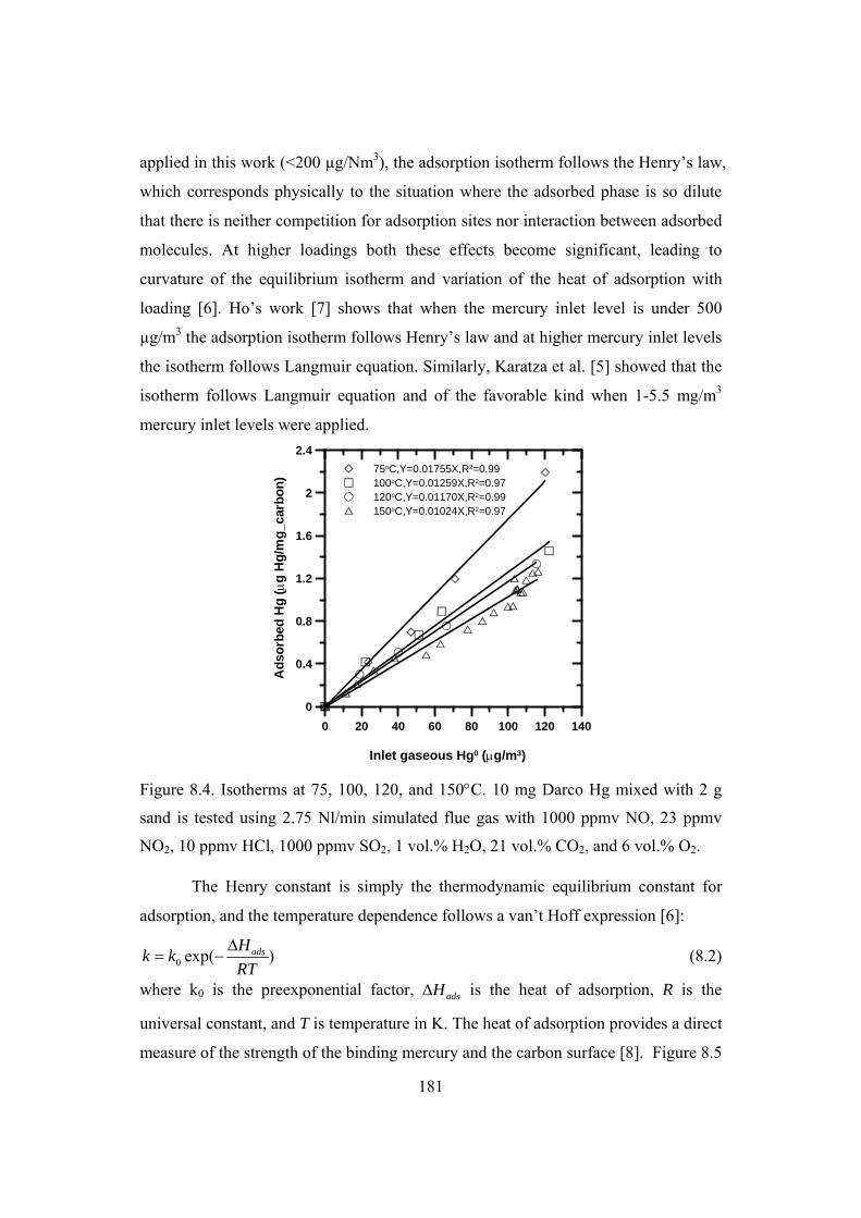
181
applied in this work (<200 µg/Nm3), the adsorption isotherm follows the Henry’s law,
which corresponds physically to the situation where the adsorbed phase is so dilute
that there is neither competition for adsorption sites nor interaction between adsorbed
molecules. At higher loadings both these effects become significant, leading to
curvature of the equilibrium isotherm and variation of the heat of adsorption with
loading [6]. Ho’s work [7] shows that when the mercury inlet level is under 500
µg/m3 the adsorption isotherm follows Henry’s law and at higher mercury inlet levels
the isotherm follows Langmuir equation. Similarly, Karatza et al. [5] showed that the
isotherm follows Langmuir equation and of the favorable kind when 1-5.5 mg/m3
mercury inlet levels were applied.
0 20 40 60 80 100 120 140
Inlet gaseous Hg0 (g/m3)
0
0.4
0.8
1.2
1.6
2
2.4
Ad
sorb
ed H
g (g
Hg
/mg
_car
bo
n)
75oC,Y=0.01755X,R2=0.99100oC,Y=0.01259X,R2=0.97120oC,Y=0.01170X,R2=0.99150oC,Y=0.01024X,R2=0.97
Figure 8.4. Isotherms at 75, 100, 120, and 150C. 10 mg Darco Hg mixed with 2 g
sand is tested using 2.75 Nl/min simulated flue gas with 1000 ppmv NO, 23 ppmv
NO2, 10 ppmv HCl, 1000 ppmv SO2, 1 vol.% H2O, 21 vol.% CO2, and 6 vol.% O2.
The Henry constant is simply the thermodynamic equilibrium constant for
adsorption, and the temperature dependence follows a van’t Hoff expression [6]:
0 exp( )adsHk k
RT
(8.2)
where k0 is the preexponential factor, adsH is the heat of adsorption, R is the
universal constant, and T is temperature in K. The heat of adsorption provides a direct
measure of the strength of the binding mercury and the carbon surface [8]. Figure 8.5

182
plots lnk as a function of the reciprocal of temperature. Since adsorption is
exothermic, the Henry constant decreases with temperature. There is a linear relation
between lnk and 1/T and from the slope and intercept the calculated value for k0 and
adsH is 0.869 m3/g and -8543 J/mol, respectively. In the work of Karatza et al. [5] a
heat of adsorption of -22000 J/mol was found for Darco G60 activated carbon tested
in nitrogen. The Darco G60 carbon has surface area of 600 m2/g and is typically used
for treating fine chemicals and pharmaceutical intermediates [9]. Calculated binding
energy of elemental mercury on activated carbon at room temperature using density
functional theory and fused-benzene ring cluster approach is -18100 J/mol [10].
Effects of other flue gas constituents have not been considered in the simulations. The
derived heat of adsorption for Darco Hg carbon in simulated cement kiln flue gas is
about half of both the experimental data for Darco G60 in nitrogen and theoretical
calculation of binding energy of elemental mercury on activated carbon in nitrogen at
room temperature.
0.0022 0.0024 0.0026 0.0028 0.003
1/T (1/K)
-4.8
-4.6
-4.4
-4.2
-4
ln(k
)
DataY=1027.4881X-7.0484R2=0.93
Figure 8.5. Plot of lnk as a function of 1/T. The Henry’s constants k are derived from
isotherms at 75, 100, 120, and 150C. 10 mg Darco Hg mixed with 2 g sand is tested
using 2.75 Nl/min simulated flue gas with 1000 ppmv NO, 23 ppmv NO2, 10 ppmv
HCl, 1000 ppmv SO2, 1 vol.% H2O, 21 vol.% CO2, and 6 vol.% O2.
The oxidation of mercury by the Darco Hg carbon seems not to be affected by
the elemental mercury inlet level, as shown in figure 8.6. The mercury oxidation is

183
always larger than 90% and the average mercury oxidation percentage is about 96%
in the studied elemental mercury inlet level of 18-180 µg/Nm3. While almost no
mercury oxidation takes place on the activated carbon tested in nitrogen. It is
expected that the heat of adsorption is different for elemental mercury and oxidized
mercury adsorption by the carbon. This might explain the difference between the
derived heat of adsorption from this work and both the experimental data for Darco
G60 in nitrogen and theoretical calculation of binding energy of elemental mercury
on activated carbon in nitrogen.
0 40 80 120 160 200
Hg inlet concentration (g/Nm3)
0
10
20
30
40
50
60
70
80
90
100
110
Mer
cury
oxi
dat
ion
(%
)
Figure 8.6. Effect of elemental mercury inlet level on mercury oxidation by 10 mg
Darco Hg mixed with 2 g sand tested at 150C using 2.75 Nl/min simulated flue gas
with 1000 ppmv NO, 23 ppmv NO2, 10 ppmv HCl, 1000 ppmv SO2, 1 vol.% H2O, 21
vol.% CO2, and 6 vol.% O2. 8.4 Effect of carbon particle size
The Darco Hg carbon has a mean diameter of only 16 µm. To be able to
observe the influence of carbon particle size on mercury adsorption, the Norit RB4
pellets are crushed and sieved to fractions having mean diameter of 38, 98, 165, and
325 µm. Figure 8.7 presents the mercury breakthrough curves for crushed Norit RB4
carbon with different particle sizes tested at 150C using simulated cement kiln flue
gas. Figure 8.8 further illustrates the effect of carbon particle size on the percentage
of mercury oxidation and initial adsorption rate. Faster mercury breakthrough is

184
observed for smaller carbon particle. The final mercury adsorption capacity is the
same at a value of 0.725 µg Hg/mg_carbon, which is about 65% of the Darco Hg
adsorption capacity at 150C. Higher mercury oxidation and initial adsorption rate are
also observed for smaller carbon particles.
0 0.2 0.4 0.6 0.8 1 1.2 1.4 1.6
Time (hour)
0
0.2
0.4
0.6
0.8
1
1.2G
aseo
us
Hg
(C
ou
t/Cin)
1 2 3
1: 38 m2: 98 m3: 325 m
Figure 8.7. Effect of particle size on mercury breakthrough for 10 mg crushed Norit
pellets in 2 g sand tested at 150C using 2.75 Nl/min simulated flue gas with 160-170
µg Hg0/Nm3, 1000 ppmv NO, 23 ppmv NO2, 10 ppmv HCl, 1000 ppmv SO2, 1 vol.%
H2O, 21 vol.% CO2, and 6 vol.% O2.
0 50 100 150 200 250 300 350
Carbon particle size (m)
0
10
20
30
40
50
60
70
80
90
100
Mer
cury
oxi
dat
ion
(%
)
0
0.5
1
1.5
2
Mer
cury
ad
sorp
tio
n r
ate
(g
Hg
/mg
_ca
rbo
n/h
)
Hg oxidationAdsorption rate for first 25 min
0 2 4 6 8
Thiele modulus

185
Figure 8.8. Effects of particle size on mercury oxidation and initial adsorption rate for
10 mg crushed Norit RB4 pellets in 2 g sand tested at 150C using 2.75 Nl/min
simulated flue gas with 160-170 µg Hg0/Nm3, 1000 ppmv NO, 23 ppmv NO2, 10
ppmv HCl, 1000 ppmv SO2, 1 vol.% H2O, 21 vol.% CO2, and 6 vol.% O2.
The observation on effect of carbon particle size can be quantified using the
well-known Thiele modulus, expressed for the first order kinetics as [11]:
e
paoxp D
SkR
(8.3)
where Rp is the carbon particle radius, kox is the oxidation rate constant for the first
order reaction, Sa is the surface area per unit mass of carbon, p is the carbon particle
density, and De is the effective diffusivity. The Thiele modulus is defined as the ratio
of an intrinsic reaction rate in the absence of mass transfer limitations to the rate of
diffusion into the particle under specified conditions. When the carbon particle size
increases, Thiele modulus becomes larger. For the smallest particle size of 38 µm the
calculated Thiele modulus is about 1. For the larger particles the Thiele modulus are
much larger than 1, indicating that the mercury oxidation by the large particles might
be limited by the internal diffusion resistance. Similar trends are observed for the
mercury oxidation percentage and initial adsorption rate, which again indicates that
mercury oxidation is an important step in elemental adsorption by the activated
carbon.
8.5 Effect of flue gas flow rate
The effect of flue gas flow rate on mercury breakthrough profile is presented
in figure 8.9. With larger flue gas flow rate the active carbon is saturated and reach
the equilibrium capacity in shorter time. The initial mercury breakthrough time,
which is defined as time when the mercury concentration after the carbon bed starts
to increase, decreases when the flow rate is increased. The final adsorption capacities
for all tested flow rates are almost the same.
A higher superficial velocity is associated with a higher total mercury input,
resulting in a faster consumption of the sorption capacity of the activated carbon and

186
corresponding higher mercury outlet concentration. While a higher superficial
velocity enhances the mass transfer rate and the corresponding mercury sorption rate.
0 0.4 0.8 1.2 1.6 2
Time (hour)
0
0.2
0.4
0.6
0.8
1
1.2
Gas
eou
s H
g C
ou
t/Cin
2750 Nml/min1830 Nml/min1100 Nml/min
Figure 8.9. Effect of flue gas flow rate on mercury breakthrough of 10 mg Darco Hg
mixed with 2 g sand tested at 150C using 2.75 Nl/min simulated flue gas with 160-
170 µg Hg0/Nm3, 1000 ppmv NO, 23 ppmv NO2, 10 ppmv HCl, 1000 ppmv SO2, 1
vol.% H2O, 21 vol.% CO2, and 6 vol.% O2.
8.6 Effects of flue gas compositions
Most of the previous work conducted the tests either in nitrogen or added
single gas to the baseline gas of either only N2 or a mixture of CO2, O2, H2O and N2
[5,11-19]. Some studies use simulated flue gas that does not contain all the relevant
gases, especially the acid gases [20-26]. It is more reasonable to change ranges of the
relevant gases instead of completely removing the gases from the baseline to simulate
the real flue gas. In this work, the concentration of relevant gas component is varied
while the concentrations of the other flue gas components remain at the baseline
values.
8.6.1 Effect of CO2
The effects of CO2 concentration in the flue gas on mercury adsorption
capacity of Darco Hg carbon at 150C are illustrated in figure 8.10. The mercury

187
adsorption capacity slightly decreases when the CO2 level in the gas is increased from
1 to 31 vol.%. The negative effects of CO2 in the flue gas on mercury adsorption by
the virgin activated carbon were also observed by Yan et al. [13]. The decrease of the
adsorption capacity in the presence of CO2 is probably due to the reduction in the
active sites for mercury adsorption due to the competitive adsorption of CO2 and
mercury on the carbon. The weak effect of CO2 on mercury adsorption might due to
the fact that significant CO2 adsorption on the activated carbon only occur at low
temperature (<50C) and high pressure [27-32].
The observation on the effects of CO2 is different from tests using a gas
mixture of Hg, N2, and CO2, which shows that the mercury adsorption capacity on
activated carbon does not change when the CO2 level is increased from 0 to, 5 and 15
vol.% [24]. Under such gas conditions CO2 in the gas behaves as an inert gas, i.e., it
neither impacts adsorption capacity of activated carbon nor does it affects the
oxidation of mercury. Tests in this work show that the mercury oxidation percentage
is about 94% for CO2 level in the gas less than 21 vol.%, while only 82% mercury
oxidation is obtained at a CO2 level of 31 vol.%.
0 5 10 15 20 25 30 35
CO2 level in gas (%)
0
0.2
0.4
0.6
0.8
1
1.2
1.4
Mer
cury
ad
sorp
tio
n c
apac
ity
(g
_Hg
/mg
_car
bo
n)
Data
Y=1.3779X-0.066
R2=0.72
Figure 8.10. Effect of CO2 concentration in the flue gas on mercury adsorption
capacity of 10 mg Darco Hg mixed with 2 g sand tested at 150C using 2.75 Nl/min

188
simulated flue gas with 160-170 µg Hg0/Nm3, 1000 ppmv NO, 23 ppmv NO2, 10
ppmv HCl, 1000 ppmv SO2, 1 vol.% H2O, and 6 vol.% O2.
8.6.2 Effect of O2
Figure 8.11 shows the effects of oxygen concentration in the flue gas on the
mercury adsorption capacity of Darco Hg at 150C. The mercury adsorption capacity
hardly changes with increasing the oxygen level from 1 vol.% to 16 vol.% when
taking the experimental uncertainty into account. In all the cases the mercury
oxidation by the carbon is about 97%.
0 4 8 12 16 20
O2 level in gas (%)
0
0.2
0.4
0.6
0.8
1
1.2
Mer
cury
ad
sorp
tio
n c
apac
ity
(g
_Hg
/mg
_car
bo
n)
Figure 8.11. Effect of O2 concentration in the flue gas on mercury adsorption capacity
of 10 mg Darco Hg mixed with 2 g sand tested at 150C using 2.75 Nl/min simulated
flue gas with 160-170 µg Hg0/Nm3, 1000 ppmv NO, 23 ppmv NO2, 10 ppmv HCl,
1000 ppmv SO2, 1 vol.% H2O, and 21 vol.% CO2.
The effects of oxygen level in the gas on mercury adsorption by activated
carbon were investigated using a gas mixture of Hg, N2, and O2 at 140C in the
literature [24]. When the oxygen concentration was increased from 0 to 3 vol.%, the
mercury adsorption capacity on the studied activated carbon remained almost
unchanged. The mercury adsorption capacity increased by 16 and 33% when the
oxygen level was further increased to 6 and 9 vol.%, respectively.

189
The possibility of carbon-oxygen complexes formation during the fixed-bed
test and their impact on mercury adsorption was investigated [24]. Pretreatment of the
unoxidized carbon by air for 7 days had no impact on the mercury adsorption
performance of the carbon. The air can oxidize carbon surface and increases its acidic
surface functional group content. However, these changes have no impact on the
performance of active carbon for mercury adsorption.
Thermodynamic calculations of mercury-oxygen reactions suggest that about
30% of the mercury could be present as HgO(g) at 200C, while at lower
temperatures HgO(s) is the dominant form, when acid gases such HCl and NOx are
not present in the gas [33,34]. This could lead to very high mercury adsorption
capacity as it is not adsorption of mercury but precipation of HgO(s) on the carbon
that takes place. However, the exact temperature range at which HgO(s) is the
dominant form was not reported. Homogenous gas phase reaction of mercury with
oxygen in an atmosphere of N2, O2, and Hg was investigated by Hall et al [34].
Results suggest that a homogeneous gas phase reaction between oxygen and
elemental mercury is not an important factor in flue gas reaction processes. The
enhanced mercury adsorption in the presence of oxygen can be explained by the
conversion of mercury to mercuric oxides as there is no reaction between oxygen and
mercury in the absence of activated carbon surface.
When HCl is present in the gas even at ppmv level, compared to vol.% level
of oxygen, elemental mercury will be mainly oxidized to HgCl2 instead of HgO as
shown by the thermodynamic calculations presented in chapter 2 [35,36]. Oxygen
was found to be a weak oxidant of mercury [37]. This could explain the weak effect
of oxygen on the mercury adsorption by Darco Hg carbon tested in simulated flue gas
in this work.
8.6.3 Effect of H2O
The effect of water in the flue gas on the mercury breakthrough profile and
mercury adsorption capacity of Darco Hg at 150C is shown in figure 8.12 and 8.13,
respectively. The presence of water in the flue gas generally accelerates the mercury
breakthrough and therefore decreases the amount of mercury adsorbed on the carbon.

190
The mercury adsorption capacity is increased significantly when water is removed
from the simulated flue gas. The mercury adsorption capacity of Darco Hg carbon
tested without water in the flue gas is about 5.5 times of that with 1 vol.% water in
the gas. However, this result is not practically important since full-scale flue gas
always contains water in percentage level [38]. Compared to CO2, the effects of H2O
in the flue gas on mercury adsorption are more pronounced. The mercury oxidation
percentage is about 97% for water level in the range of 0-15 vol.%, however, the
mercury oxidation decreases to 68% when 25 vol.% of water is added to the flue gas.
As a result the mercury adsorption capacity of Darco Hg with 25 vol.% water is only
about 44% of that with 1 vol.% water in the flue gas.
0 1 2 3 4 5 6
Time (hour)
0
0.2
0.4
0.6
0.8
1
1.2
Gas
eou
s H
g, C
ou
t/Cin
1 2 3
1: 8% H2O2:1% H2O3:0% H2O
Figure 8.12. Effects of water concentration in the flue gas on mercury breakthrough
profile of 10 mg Darco Hg mixed with 2 g sand tested at 150C using 2.75 Nl/min
simulated flue gas with 160-170 µg Hg0/Nm3, 1000 ppmv NO, 23 ppmv NO2, 10
ppmv HCl, 1000 ppmv SO2, 6 vol.% O2, and 21 vol.% CO2.

191
0 5 10 15 20 25 30
H2O level in gas (%)
0
0.2
0.4
0.6
0.8
1
1.2
Mer
cury
ad
sorp
tio
n c
apac
ity
(g
_Hg
/mg
_car
bo
n)
Data
Y=1.1277X-0.261
R2=0.98
Figure 8.13. Effects of water concentration in the flue gas on mercury adsorption
capacity of 10 mg Darco Hg mixed with 2 g sand tested at 150C using 2.75 Nl/min
simulated flue gas with 160-170 µg Hg0/Nm3, 1000 ppmv NO, 23 ppmv NO2, 10
ppmv HCl, 1000 ppmv SO2, 6 vol.% O2, and 21 vol.% CO2. The regressed equation
of mercury adsorption capacity is not valid for H2O level of zero.
Tests in N2, Hg, and H2O at 140C show that the mercury adsorption capacity
of sulfur impregnated activated carbon does not change significantly when the water
content in the gas is increased from 0 to 5 vol.% [24]. While the adsorption capacity
decreases about 25% when the water content is further increased to 10 vol.%. This is
in contrast to tests with simulated flue gas in this work, as the mercury adsorption
capacity always decreases with water addition in the flue gas.
The negative effects of water presence in the gas on mercury adsorption by
the carbon could be due to the competitive adsorption of water on the carbon. Water
adsorption on carbon has been studied by several researchers [39-42]. Due to the
strong chemisorption of water molecules with the acidic oxygen functional group on
the carbon, the initial water adsorption occurs at the functional groups, and further
water adsorption will occur on top of the chemisorbed water molecules via hydrogen
bonding [42].

192
8.6.4 Effect of CO
Unlike most other combustion processes, organic constituents in the raw
material for clinker production result in CO emissions, even under optimized
combustion conditions. In the preheater, these organic components in the raw
material are liberated, part of them being emitted with the exhaust gas. The carbon
monoxide concentration in the exhaust gas from cement rotary kiln systems ranges
between 0.1 and 5 g/Nm³ (80-4000 ppmv) [43]. There is no reported investigation on
possible effect of CO on mercury adsorption by the activated carbon.
The effect of CO concentration in the flue gas on the mercury adsorption
capacity of Darco Hg carbon at 150C is illustrated in figure 8.14. Similar to the
effects of oxygen, the mercury adsorption capacity is not affected by the presence of
CO in the range of 0-1000 ppmv.
0 200 400 600 800 1000 1200
CO level in the gas (ppmv)
0
0.2
0.4
0.6
0.8
1
1.2
1.4
Mer
cury
ad
sorp
tio
n c
apac
ity
(g
Hg
/mg
_car
bo
n)
Figure 8.14. Effects of CO concentration in the flue gas on mercury adsorption
capacity of 10 mg Darco Hg mixed with 2 g sand tested at 150C using 2.75 Nl/min
simulated flue gas with 160-170 µg Hg0/Nm3, 1000 ppmv NO, 23 ppmv NO2, 10
ppmv HCl, 1000 ppmv SO2, 1 vol.% H2O, 6 vol.% O2, and 21 vol.% CO2.
As shown in figure 8.15, there is a slight decrease of mercury oxidation
percentage when the CO level in the flue gas is increased. The mercury oxidation
decreases from 98% when less than 100 ppmv CO is present in the flue gas to 85%

193
with 1000 ppmv CO in the flue gas. This is probably because oxidized mercury is
reduced at higher CO levels.
0 200 400 600 800 1000
CO level in flue gas (ppmv)
0
10
20
30
40
50
60
70
80
90
100
110
Mer
cury
oxi
dat
ion
(%
)
Figure 8.15. Effects of CO concentration in the flue gas on mercury oxidation by 10
mg Darco Hg mixed with 2 g sand tested at 150C using 2.75 Nl/min simulated flue
gas with 160-170 µg Hg0/Nm3, 1000 ppmv NO, 23 ppmv NO2, 10 ppmv HCl, 1000
ppmv SO2, 1 vol.% H2O, 6 vol.% O2, and 21 vol.% CO2.
8.6.5 Effect of SO2
The effect of SO2 in the flue gas on mercury breakthrough profile and
adsorption capacity of Darco Hg at 150C is presented in figure 8.16 and 8.17,
respectively. There are strong effects of SO2 in the flue gas on the mercury adsorption
by the activated carbon. The mercury adsorption capacity decreases when the SO2
level in the flue gas is increased. The mercury adsorption capacity of Darco Hg
carbon tested with 100 ppmv SO2 in the flue gas is about 4 times of that tested with
1000 ppmv SO2 in the flue gas. Dunham et al. [44] also found that the mercury
adsorption capacity of activated carbon is inversely affected by SO2 in the flue gas
with reductions in adsorption capacity noted at concentrations as low as 100 ppmv
SO2. The mercury oxidation is not affected by changing the SO2 level in the flue gas
and is about 97% for SO2 added in the range of 100-1000 ppmv.

194
0 0.5 1 1.5 2 2.5 3 3.5
Time (hour)
0
0.2
0.4
0.6
0.8
1
1.2
Gas
eou
s H
g, C
ou
t/Cin
1 2
3 4
1: 1000 ppmv SO2
2: 500 ppmv SO2
3: 300 ppmv SO2
4: 100 ppmv SO2
Figure 8.16. Effects of SO2 concentration in the flue gas on mercury breakthrough
profile of 10 mg Darco Hg mixed with 2 g sand tested at 150C using 2.75 Nl/min
simulated flue gas with 160-170 µg Hg0/Nm3, 1000 ppmv NO, 23 ppmv NO2, 10
ppmv HCl, 1 vol.% H2O, 6 vol.% O2, and 21 vol.% CO2.
0 200 400 600 800 1000 1200
SO2 level in gas (ppmv)
0
1
2
3
4
5
Mer
cury
ad
sorp
tio
n c
apac
ity
(g
_Hg
/mg
_car
bo
n)
Data,Hg
Y=69.176X-0.592
R2=0.99
Figure 8.17. Effects of SO2 concentration in the flue gas on mercury adsorption
capacity of 10 mg Darco Hg mixed with 2 g sand tested at 150C using 2.75 Nl/min
simulated flue gas with 160-170 µg Hg0/Nm3, 1000 ppmv NO, 23 ppmv NO2, 10
ppmv HCl, 1 vol.% H2O, 6 vol.% O2, and 21 vol.% CO2. The regressed equation of
mercury adsorption capacity is valid for SO2 level higher than 100 ppmv.

195
Without the presence of NOx in the gas, the mercury adsorption capacity of
activated carbon is also reported to decrease when the SO2 concentration increases
[38]. This might be explained by the oxidation of SO2 to SO3 on the activated carbon
and the inhibiting effect of SO3 on mercury capture by activated carbon injection has
been observed in full-scale power plant tests [45,46]. In addition to removing
mercury, activated carbon is also used as catalyst for oxidation SO2 to sulphuric acid
and as SO2 sorbent [47,48]. There is competitive adsorption between Hg and SO3
since both mercury and SO3 bind to the Lewis base sites on the activated carbon
surface [45,49]. Some activated carbon catalysts for converting SO2 to H2SO4 are
self-poisoned by SO3 or sulfate buildup on the surface. Therefore, a similar
phenomenon might explain the inhibiting effect of SO3 on mercury capture.
Previous results demonstrated that the oxidation of SO2 on carbon particles
was greatly enhanced by the presence of trace quantities of gaseous NO2 [50-53].
NO2 is an efficient oxidant for SO2 sorbed on carbon. According to the mechanisms
of flue gas and mercury interactions on activated carbon proposed by Dunham et al.
[44] and Olson et al. [54], sulfurous acid that accumulates from the hydration of SO2
converts the previously formed nonvolatile basic mercuric nitrate into the volatile
form. This results in the slow release of previously captured mercury over time in the
presence of NO2 and SO2.
8.6.6 Effect of HCl
Figure 8.18 illustrates the effects of HCl in the flue gas on the mercury
adsorption capacity of Darco Hg tested at 150C. There are weak effects of HCl
concentration in the flue gas on mercury adsorption capacity when 0.5-20 ppmv HCl
is added to the flue gas. The mercury adsorption capacity increases gradually when
the HCl level is increased from 0.5 to 5 ppmv and then it levels off when the HCl
level is further increased. The mercury oxidation percentage is about 97% for all the
tested HCl levels except that only 87% mercury oxidation is obtained when 0.5 ppmv
HCl is added to the gas.

196
0 4 8 12 16 20 24
HCl level in gas (ppmv)
0
0.2
0.4
0.6
0.8
1
1.2
1.4
Mer
cury
ad
sorp
tio
n c
apac
ity
(g
_Hg
/mg
_car
bo
n)
Data
Y=0.9728X0.071
R2=0.82
Figure 8.18. Effects of HCl concentration in the flue gas on mercury adsorption
capacity of 10 mg Darco Hg mixed with 2 g sand tested at 150C using 2.75 Nl/min
simulated flue gas with 160-170 µg Hg0/Nm3, 1000 ppmv NO, 23 ppmv NO2, 1000
ppmv SO2, 1 vol.% H2O, 6 vol.% O2, and 21 vol.% CO2. The regressed equation of
mercury adsorption capacity is valid for HCl level higher than 0.5 ppmv.
Strong promoting effects of HCl on mercury adsorption by activated carbon
in the simulated flue gas without NOx at 135C have been reported by Carey et al.
[38]. Addition of HCl to the simulated gases of 1600 ppmv SO2, 6% O2, 12% CO2
and 7% H2O results in an increase of equilibrium adsorption capacity for elemental
mercury from 0 at 0 ppmv HCl to a value approaching 3 µg Hg/mg_carbon in the
range of 50–100 ppmv HCl. The adsorption capacity does not change significantly
above 50 ppm HCl.
When NOx is included the simulated flue gas, the promoting effects of HCl on
adsorption capacity of activated carbon becomes less pronounced. Mercury can be
adsorbed by the carbon without HCl presence in the gas, provided that NOx is present.
To study whether mercury can be adsorbed by the activated carbon in the absence of
HCl, one test was conducted by removing HCl from the baseline flue gas applied in
this work. Figure 8.19 shows the mercury breakthrough curve for 10 mg Darco Hg in
2 g sand at150C.

197
0 0.4 0.8 1.2 1.6
Time (hour)
0
0.2
0.4
0.6
0.8
1
1.2
Gas
eou
s H
g, C
ou
t/Cin
10 ppmv HCl
0 ppmv HCl
Figure 8.19. Comparison of mercury breakthrough curves with 0 and 10 ppmv HCl in
the simulated flue gas, 10 mg Darco Hg mixed with 2 g sand and tested at 150C
using 2.75 Nl/min simulated flue gas with 160-170 µg Hg0/Nm3, 1000 ppmv NO, 23
ppmv NO2, 1000 ppmv SO2, 1 vol.% H2O, 6 vol.% O2, and 21 vol.% CO2.
Figure 8.19 compares the mercury breakthrough curves of 0 and 10 ppmv
HCl in the simulated cement kiln flue gas. Test without HCl in the gas shows that
large amount of mercury is adsorbed on the carbon and mercury breakthrough is not
obtained after 10 h (not shown in figure 8.19). This might be due to the fact that
HgCl2 will form when HCl is present in the gas and on the other hand HgO or HgSO4
will form when HCl is not present through following reactions:
HgOOHg 22 2 (8R1)
NOHgONOHg 2 (8R2)
422 HgSOSOOHg (8R3)
HgO(s) is easily captured by the carbon since it might condense on the carbon at the
applied adsorption temperature of 150C.
8.6.7 Effect of NO
As shown in figure 8.20, changing of NO concentration in the simulated flue
gas does not affect the adsorption capacity of Darco Hg tested at 150C. The mercury

198
oxidation extent by the Darco Hg carbon is about 98% for tested NO in the range of
100-1000 ppmv.
0 200 400 600 800 1000 1200
NO level in gas ( ppmv)
0
0.2
0.4
0.6
0.8
1
1.2
Mer
cury
ad
sorp
tio
n c
apac
ity
(g
_Hg
/mg
_car
bo
n)
Figure 8.20. Effects of NO concentration in the flue gas on mercury adsorption
capacity of 10 mg Darco Hg mixed with 2 g sand tested at 150C using 2.75 Nl/min
simulated flue gas with 160-170 µg Hg0/Nm3, 10 ppmv HCl, 23 ppmv NO2, 1000
ppmv SO2, 1 vol.% H2O, 6 vol.% O2, and 21 vol.% CO2.
Strong promoting effects of NO on mercury adsorption by the activated
carbon have been reported when 300 ppmv NO was added to baseline gas with 8
vol.% H2O, 6 vol.% O2, and 12 vol.% CO2 at 107C [5,11-19]. Liu et al. [24] reported
that adding 500 ppmv NO to nitrogen did not change the mercury adsorption by the
activated carbon at 140C. Fan et al. [55] proposed that the promoting effects of NO
on mercury adsorption by the activated carbon is due to the reaction of NO with O2 to
form NO2 and active O atoms that could further react with elemental mercury. Thus
the effects of NO on mercury adsorption depend on the presence of other acid gases
in the flue gas. With HCl and NO2 presence in the gas the effects of NO are less
significant.
8.6.8 Effect of NO2
The effect of NO2 in the flue gas on mercury breakthrough profile and
adsorption capacity of Darco Hg at 150C is presented in figure 8.21 and 8.22,

199
respectively. The mercury oxidation by the Darco Hg carbon is about 98% for tested
NO2 in the range of 0-100 ppmv. Dunham et al. [44] also found that the mercury
adsorption capacity of activated carbon is inversely proportional to the concentrations
of NO2 in the simulated flue gas. A decrease in the mercury adsorption capacity of
activated carbon was observed at concentrations as low as 2.5 ppmv NO2. The
negative effects of NO2 are again due to the interaction between NO2 and SO2, as
discussed in section 8.6.5.
0 0.2 0.4 0.6 0.8 1 1.2
Time (hour)
0
0.2
0.4
0.6
0.8
1
1.2
Gas
eou
s H
g, C
ou
t/Cin
1 2 3
1: 100 ppmv NO2
2: 23 ppmv NO2
3: 5 ppmv NO2
Figure 8.21. Effects of NO2 concentration in the flue gas on mercury breakthrough
curves of 10 mg Darco Hg mixed with 2 g sand tested at 150C using 2.75 Nl/min
simulated flue gas with 160-170 µg Hg0/Nm3, 10 ppmv HCl, 1000 ppmv NO, 1000
ppmv SO2, 1 vol.% H2O, 6 vol.% O2, and 21 vol.% CO2.

200
0 20 40 60 80 100 120
NO2 level in gas (ppmv)
0
0.2
0.4
0.6
0.8
1
1.2
1.4
1.6
Mer
cury
ad
sorp
tio
n c
apac
ity
(g
_Hg
/mg
_car
bo
n)
Data
Y=2.0685X-0.199
R2=0.89
Figure 8.22. Effects of NO2 concentration in the flue gas on mercury adsorption
capacity of 10 mg Darco Hg mixed with 2 g sand tested at 150C using 2.75 Nl/min
simulated flue gas with 160-170 µg Hg0/Nm3, 10 ppmv HCl, 1000 ppmv NO, 1000
ppmv SO2, 1 vol.% H2O, 6 vol.% O2, and 21 vol.% CO2. The regressed equation of
mercury adsorption capacity is not valid when NO2 is not presented in the gas.
Table 8.2 summarizes the regressed equations of Darco Hg carbon mercury
adsorption capacity as a function of flue gas composition at 150C. From these
equations it is possible estimate mercury adsorption capacity in a wide range of glue
gas composition.
Table 8.2 Summary of regressed equations of Darco Hg carbon mercury adsorption
capacity as a function of flue gas composition at 150C.
Gases Concentration unit Concentration range Equations CO2 % >0 Y=1.3779X-0.066 H2O % >0 Y=1.1277X-0.261 SO2 ppmv ≥100 Y=69.176X-0.592 HCl ppmv ≥0.5 Y=0.9728X0.071 NO2 ppmv >0 Y=2.0685X-0.199

201
8.7 Conclusions
A parametric study of elemental mercury adsorption by activated carbon has
been conducted in the fixed-bed reactor by mixing 10 mg Darco Hg carbon with 2 g
sand and using simulated cement kiln flue gas. Equilibrium mercury adsorption
capacity, initial adsorption rate and mercury oxidation percentage are evaluated.
Increasing adsorption temperature results in decreased equilibrium mercury
adsorption capacity of the activated carbon. The mercury adsorption isotherm follows
Henry’s law for the applied mercury inlet levels in this project at all tested
temperatures. All these are consistent with a physical adsorption mechanism. The
derived heat of adsorption is -8543 J/mol for elemental mercury adsorption by Darco
Hg activated carbon in simulated cement kiln flue gas.
The effects of carbon particle size were investigated using the crushed Norit
RB4 pellets. Higher mercury oxidation and initial adsorption rate are observed for
smaller carbon particles, while the equilibrium mercury adsorption capacity is the
same.
The effects of flue gas composition are investigated by varying the
concentrations of relevant gases instead of complete removal of the single gas from
the baseline to simulate the real flue gas. The mercury adsorption capacity does not
change with changes in the O2, CO, and NO levels in the flue gas. The mercury
adsorption capacity decreases when CO2, H2O, SO2, and NO2 concentrations in the
flue gas increase. The following correlation between mercury adsorption capacity and
these gas concentrations are obtained at 150C: mercury adsorption capacity is
proportional to CCO2-0.066, CH2O
-0.261, CSO2-0.592, CNO2
-0.199. The decrease of mercury
adsorption capacity is due to the competition for active site with mercury by CO2 and
H2O, and conversion of the previously formed nonvolatile basic mercuric nitrate into
the volatile form by interactions between SO2 and NO2.
Slight promoting effects of HCl on mercury adsorption are observed when
HCl concentration is varied in the range of 0.5-20 ppmv. A larger mercury adsorption
capacity is obtained when HCl is removed from baseline gas. This might due to the
fact that HgCl2 will form when HCl is present in the gas while HgO(s) will form

202
when HCl is not present. HgO is more easily captured by the carbon since it
condenses on the carbon at the applied adsorption temperature of 150C.
Significant mercury oxidation is observed by the activated carbon. Even for
10 mg carbon typically an oxidation level of 94-97% is found. Increasing CO and
water level in the flue gas causes a slight decrease of mercury oxidation. Larger
mercury oxidation percentage is obtained with smaller carbon particle size. All these
observations indicate that mercury oxidation by HCl, when this is present in the gas,
is an important step in elemental adsorption by the activated carbon.
8.8 References
[1] A.J. Cruz, J. Pires, A.P. Carvalho, D.C. Brotas, Adsorption of acetic acid by activated
carbons, zeolites, and other adsorbent materials related with the preventive conservation of
lead objects in museum showcases, Journal of Chemical & Engineering Data. 49 (2004) 725-
731.
[2] A. Bagreev, T.J. Bandosz, H2S adsorption/oxidation on unmodified activated carbons:
importance of prehumidification, Carbon. 39 (2001) 2303-2311.
[3] D.D. Do, Adsorption analysis: equilibria and kinetics, Imperial College Press, 1998.
[4] R.C. Bansal, M. Goyal, Activated carbon adsorption, CRC Press, 2005.
[5] D. Karatza, A. Lancia, D. Musmarra, F. Pepe, Adsorption of metallic mercury on
activated carbon, Symp. Int. Combust. 26 (1996) 2439-2445.
[6] H.G. Karge, J. Weitkamp, (Eds.), Molecular sieves-science and technology, volume 7,
Adsorption and diffusion,Springer-Verlag Berlin Heidelberg, 2008.
[7] T.C. Ho, N. Kobayashi, Y. Lee, J. Lin, J.R. Hopper, Experimental and kinetic study of
mercury adsorption on various activated carbons in a fixed-bed adsorber, Environ. Eng. Sci.
21 (2004) 21-27.
[8] D.M. Ruthven, Principles of adsorption and adsorption processes, John Wiley & Sons,
Inc., 1984.
[9] D.O. Cooney, A.L. Hines, Extractive purification of activated carbon. 1. Effect of acid
normality, volume, and repeated contact, Industrial & Engineering Chemistry Process Design
and Development. 22 (1983) 208-211.
[10] B. Padak, M. Brunetti, A. Lewis, J. Wilcox, Mercury binding on activated carbon,
Environmental Progress. 25(2006) 319-326.
[11] G. Skodras, I. Diamantopoulou, G. Pantoleontos, G.P. Sakellaropoulos, Kinetic studies
of elemental mercury adsorption in activated carbon fixed bed reactor, Journal of Hazardous
Materials. 158 (2008) 1-13.
[12] S.J. Miller, G.E. Dunham, E.S. Olson, T.D. Brown, Flue gas effects on a carbon-based
mercury sorbent, Fuel Processing Technology. 65-66 (2000) 343-363.

203
[13] R. Yan, Y.L. Ng, D.T. Liang, C.S. Lim, J.H. Tay, Bench-scale experimental study on the
effect of flue gas composition on mercury removal by activated carbon adsorption, Energy
Fuels. 17 (2003) 1528-1535.
[14] I. Diamantopoulou, G. Skodras, G.P. Sakellaropoulos, Sorption of mercury by activated
carbon in the presence of flue gas components, Fuel Process Technol. 91 (2010) 158-163.
[15] R. Yan, D.T. Liang, L. Tsen, Y.P. Wong, Y.K. Lee, Bench-scale experimental
evaluation of carbon performance on mercury vapour adsorption, Fuel. 83 (2004) 2401-2409.
[16] J.A. Korpiel, R.D. Vidic, Effect of sulfur impregnation method on activated carbon
uptake of gas-phase mercury, Environ. Sci. Technol. 31 (1997) 2319-2325.
[17] S. Lee, Y. Park, Gas-phase mercury removal by carbon-based sorbents, Fuel Process
Technol. 84 (2003) 197-206.
[18] S.J. Lee, Y. Seo, J. Jurng, T.G. Lee, Removal of gas-phase elemental mercury by iodine-
and chlorine-impregnated activated carbons, Atmospheric Environment. 38 (2004) 4887-
4893.
[19] D. Karatza, A. Lancia, D. Musmarra, C. Zucchini, Study of mercury absorption and
desorption on sulfur impregnated carbon, Experimental Thermal and Fluid Science. 21 (2000)
150-155.
[20] H.C. Hsi, S. Chen, M. Rostam-Abadi, M.J. Rood, C.F. Richardson, T.R. Carey, R.
Chang, Preparation and evaluation of coal-derived activated carbons for removal of mercury
vapor from simulated coal combustion flue gases, Energy Fuels. 12 (1998) 1061-1070.
[21] S.B. Ghorishi and B.K. Gullett, An experimental study on mercury sorption by activated
carbons and calcium hydroxide, The Fifth Annual North American Waste-to-Energy
Conference, Research Triangle Park, NC, 22-25 April, 1997.
[22] S. Eswaran, H.G. Stenger, Z. Fan, Gas-phase mercury adsorption rate studies, Energy
Fuels. 21 (2007) 852-857.
[23] R. Ochiai, M.A. Uddin, E. Sasaoka, S. Wu, Effects of HCl and SO2 concentration on
mercury removal by activated carbon sorbents in coal-derived flue gas, Energy & Fuels. 23
(2009) 4734.
[24] W. Liu, R.D. Vidic, T.D. Brown, Impact of flue gas conditions on mercury uptake by
sulfur-impregnated activated carbon, Environ. Sci. Technol. 34 (2000) 154-159.
[25] G.E. Dunham, S.J. Miller, Mercury capture by an activated carbon in a fixed-bed bench-
scale system, Environmental Progress. 17 (1998) 203.
[26] S. Lee, J. Lee, T.C. Keener, Novel sorbents for mercury emissions control from coal-
fired power plants, Journal of the Chinese Institute of Chemical Engineers. 39 (2008) 137-
142.
[27] M. Molina-Sabio, A.M.A. Muñecas, F. Rodríguez-Reinoso, B. McEnaney, Adsorption
of CO2 and SO2 on activated carbons with a wide range of micropore size distribution,
Carbon. 33 (1995) 1777-1782.

204
[28] T.C. Drage, O. Kozynchenko, C. Pevida, M.G. Plaza, F. Rubiera, J.J. Pis, C.E. Snape, S.
Tennison, Developing activated carbon adsorbents for pre-combustion CO2 capture, Energy
Procedia. 1 (2009) 599-605.
[29] M.G. Plaza, S. García, F. Rubiera, J.J. Pis, C. Pevida, Post-combustion CO2 capture with
a commercial activated carbon: Comparison of different regeneration strategies, Chem. Eng.
J. 163 (2010) 41-47.
[30] C. Shen, C.A. Grande, P. Li, J. Yu, A.E. Rodrigues, Adsorption equilibria and kinetics
of CO2 and N2 on activated carbon beads, Chem. Eng. J. 160 (2010) 398-407.
[31] Y. Sun, Y. Wang, Y. Zhang, Y. Zhou, L. Zhou, CO2 sorption in activated carbon in the
presence of water, Chemical Physics Letters. 437 (2007) 14-16.
[32] B. Guo, L. Chang, K. Xie, Adsorption of carbon dioxide on activated carbon, Journal of
Natural Gas Chemistry. 15 (2006) 223-229.
[33] B. Hall, O. Lindqvist, E. Ljungstroem, Mercury chemistry in simulated flue gases related
to waste incineration conditions, Environ. Sci. Technol. 24 (1990) 108-111.
[34] B. Hall, P. Schager, J. Weesmaa, The homogeneous gas phase reaction of mercury with
oxygen, and the corresponding heterogeneous reactions in the presence of activated carbon
and fly ash, Chemosphere. 30 (1995) 611-627.
[35] C.L. Senior, A.F. Sarofim, T. Zeng, J.J. Helble, R. Mamani-Paco, Gas-phase
transformations of mercury in coal-fired power plants, Fuel Process Technol. 63 (2000) 197-
213.
[36] R.N. Sliger, J.C. Kramlich, N.M. Marinov, Towards the development of a chemical
kinetic model for the homogeneous oxidation of mercury by chlorine species, Fuel Process
Technol. 65-66 (2000) 423-438.
[37] Niksa, S. and J. J. Helble, Interpreting laboratory test data on homogeneous mercury
oxidation in coal-derived exhausts. EPA-DOE-EPRI Combined Power Plant Air Pollution
Control Symposium: The Mega Symposium and the A&WMA Specialty Conference on
Mercury Emissions: Fate, Effects, and Control, Chicago, Illinois, August 2001.
[38] T.R. Carey, O.W. Hargrove Jr, C.F. Richardson, R. Chang, F.B. Meserole, Factors
affecting mercury control in utility flue gas using activated carbon, Journal of the Air &
Waste Management Association. 48 (1998) 1166.
[39] M.M. Dubinin, V.V. Serpinsky, Isotherm equation for water vapor adsorption by
microporous carbonaceous adsorbents, Carbon. 19 (1981) 402-403.
[40] M.M. Dubinin, Water vapor adsorption and the microporous structures of carbonaceous
adsorbents, Carbon. 18 (1980) 355-364.
[41] F. Stoeckli, T. Jakubov, A. Lavanchy, Water adsorption in active carbons described by
the Dubinin-Astakhov equation, Journal of the Chemical Society, Faraday Transactions. 90
(1994) 783-786.
[42] D.D. Do, H.D. Do, A model for water adsorption in activated carbon, Carbon. 38 (2000)
767-773.

205
[43] ECRA (European cement research academy), Carbon monoxide formation and burn-out
during the clinker burning process, News letter 2, 2008.
[44] G.E. Dunham, E.S. Olson and S.J. Miller, Impact of flue gas constituents on carbon
sorbents, McLean, VA, September 19-21, 2000.
[45] A.A. Presto, E.J. Granite, Impact of sulfur oxides on mercury capture by activated
carbon, Environ. Sci. Technol. 41 (2007) 6579-6584.
[46] J. Jarvis, F. Meserole, SO3 Effect on Mercury Control, Power Eng. 112 (2008) 54-60.
[47] E. Raymundo-Piñero, D. Cazorla-Amorós, C. Salinas-Martinez de Lecea, A. Linares-
Solano, Factors controlling the SO2 removal by porous carbons: relevance of the SO2
oxidation step, Carbon. 38 (2000) 335-344.
[48] E. Raymundo-Piñero, D. Cazorla-Amorós, A. Linares-Solano, Temperature programmed
desorption study on the mechanism of SO2 oxidation by activated carbon and activated
carbon fibres, Carbon. 39 (2001) 231-242.
[49] A.A. Presto, E.J. Granite, A. Karash, Further investigation of the impact of sulfur oxides
on mercury capture by activated carbon, Ind Eng Chem Res. 46 (2007) 8273-8276.
[50] W.R. Cofer III, D.R. Schryer, R.S. Rogowski, The enhanced oxidation of SO2 by NO2
on carbon particulates, Atmospheric Environment (1967). 14 (1980) 571-575.
[51] W.R. Cofer III, D.R. Schryer, R.S. Rogowski, The oxidation of SO2 on carbon particles
in the presence of O3, NO2 and N2O, Atmospheric Environment (1967). 15 (1981) 1281-1286.
[52] W.R. Cofer III, D.R. Schryer, R.S. Rogowski, Oxidation of SO2 by NO2 and O3 on
carbon: Implications to tropospheric chemistry, Atmospheric Environment (1967). 18 (1984)
243-245.
[53] J.A. Rodriguez, T. Jirsak, J. Dvorak, S. Sambasivan, D. Fischer, Reaction of NO2 with
Zn and ZnO: Photoemission, XANES, and density functional studies on the formation of NO3,
The Journal of Physical Chemistry B. 104 (2000) 319-328.
[54] E.S. Olson, B.A. Mibeck, S.A. Benson, J.D. Laumb, C.R. Crocker, G.E. Dunham, et al.,
The mechanistic model for flue gas-mercury interactions on activated carbons: The oxidation
site, Prepr. Pap. -Am. Chem. Soc. , Div. Fuel Chem. 49 (2004) 279-280.
[55] X. Fan, C. Li, Zeng Guangming, Z. Gao, L. Chen, W. Zhang, et al., Removal of gas-
phase element mercury by activated carbon fiber impregnated with CeO2, Energy & Fuels. 24
(2010) 4250-4254.

206
9
Fundamental investigation of mercury
chloride adsorption by activated carbon in
simulated cement kiln flue gas
This chapter deals with a fundamental investigation of mercury chloride
adsorption by the Darco Hg activated carbon in simulated cement kiln flue gas. The
results are compared with tests using elemental mercury.
9.1 Introduction
Compared to research on elemental mercury adsorption [1-13], there are few
studies on mercury chloride adsorption by activated carbon [1,2,14-16]. Some of
these studies conducted tests using simulated flue gases containing 1600 ppmv SO2,
50 ppmv HCl, 12 vol.% CO2, 7 vol.% H2O, 6 vol.% O2, but without NOx [1,2,14].
Carey et al. [15] performed tests using simulated flue gas with 1600 ppmv SO2, 1-50
ppmv HCl, 10-12 vol.% CO2, 8 vol.% H2O, 6 vol.% O2, and 200-400 ppmv NOx. The
research [15] focused on a comparison of mercury adsorption capacity obtained in a
fixed-bed reactor using simulated flue gas and real power plant flue gas. Mibeck et al.
[16] investigated the effects of acid gases by adding 1600 ppmv SO2, 50 ppmv HCl,
400 ppmv NO, and 20 ppmv NO2 alone or in combination to baseline gas of 12 vol.%
CO2, 8 vol.% H2O, 6 vol.% O2. Only breakthrough curves are presented, neither
adsorption capacity nor kinetics is reported in their work.
In this work, mercury chloride adsorption capacity and kinetics are
investigated by varying the relevant gas concentrations and operating parameters.

207
9.2 Effect of temperature
The effect of temperature on mercury chloride adsorption is investigated by
applying the same conditions as for the study with elemental mercury source reported
in chapter 8. The breakthrough curves using HgCl2 source are compared with those
obtained with elemental mercury at 100, 120, and 150C, as illustrated in figure 9.1-3.
In contrast to the breakthrough curve obtained with elemental mercury, the
breakthrough curve of mercury chloride often has an introduction period. It takes
some time to reach the lowest outlet mercury concentration after switching the flue
gas with mercury chloride to the carbon bed. While the outlet mercury decreases to
the lowest value almost simultaneously after switching the flue gas with elemental
mercury to the carbon bed. This phenomenon is also observed by Mibeck et al. [16].
They also reported that about 90-95% of mercury after the carbon bed is oxidized
mercury. Measurement in this work shows that all the mercury after the carbon bed is
oxidized mercury, i.e., no reduction takes place.
0 0.2 0.4 0.6 0.8 1
Time (hour)
0
0.2
0.4
0.6
0.8
1
1.2
Ga
se
ou
s H
g, C
ou
t/Cin
Hg0, 170g/Nm3 Hg, 1.183 g Hg/mg_carbon
HgCl2, 183g/Nm3 Hg, 1.224 g Hg/mg_carbon
Figure 9.1. Comparison of breakthrough curves obtained using mercury chloride and
elemental mercury source for 10 mg Darco Hg carbon mixed with 2 g sand tested at
150C using 2.75 Nl/min simulated flue gas with 1000 ppmv NO, 23 ppmv NO2,
1000 ppmv SO2, 10 ppmv HCl, 1 vol.% H2O, 6 vol.% O2, and 21 vol.% CO2.
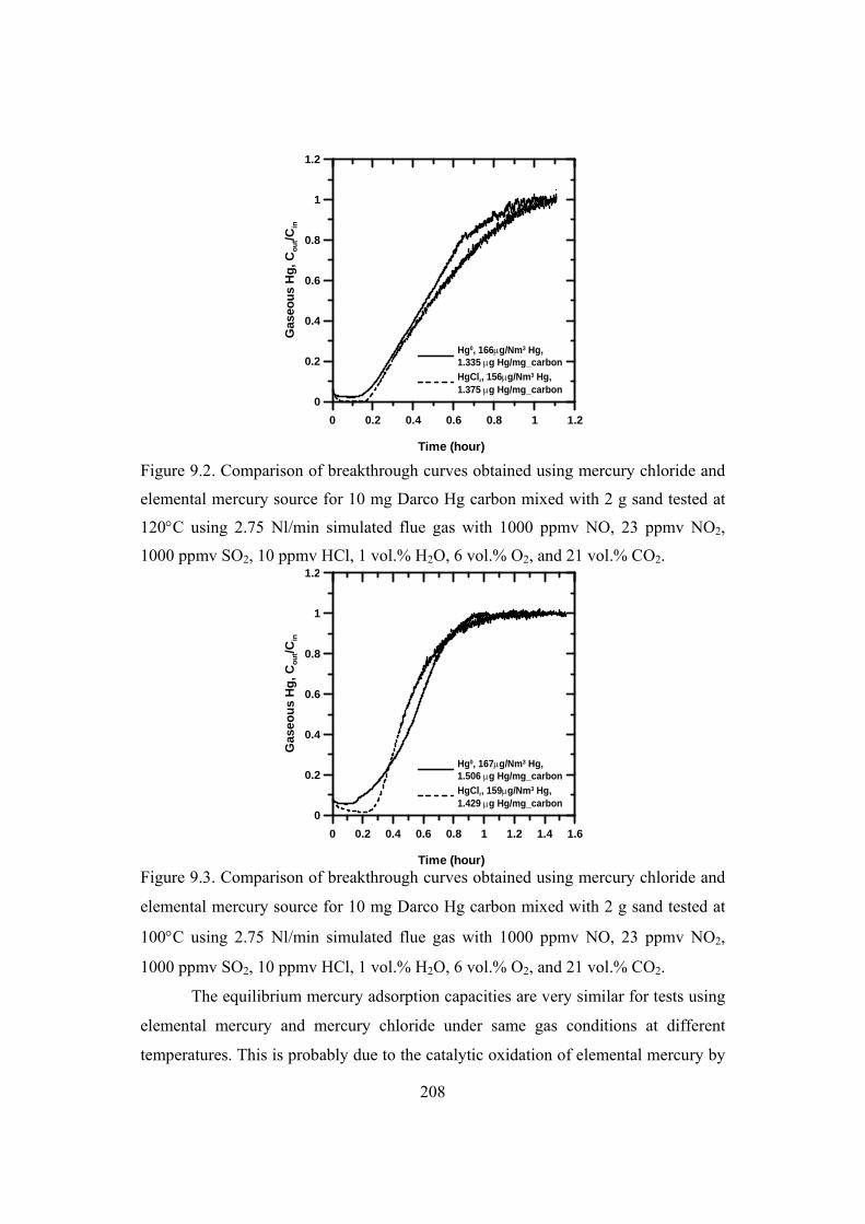
208
0 0.2 0.4 0.6 0.8 1 1.2
Time (hour)
0
0.2
0.4
0.6
0.8
1
1.2
Gas
eou
s H
g, C
ou
t/Cin
Hg0, 166g/Nm3 Hg, 1.335 g Hg/mg_carbon
HgCl2, 156g/Nm3 Hg, 1.375 g Hg/mg_carbon
Figure 9.2. Comparison of breakthrough curves obtained using mercury chloride and
elemental mercury source for 10 mg Darco Hg carbon mixed with 2 g sand tested at
120C using 2.75 Nl/min simulated flue gas with 1000 ppmv NO, 23 ppmv NO2,
1000 ppmv SO2, 10 ppmv HCl, 1 vol.% H2O, 6 vol.% O2, and 21 vol.% CO2.
0 0.2 0.4 0.6 0.8 1 1.2 1.4 1.6
Time (hour)
0
0.2
0.4
0.6
0.8
1
1.2
Ga
seo
us
Hg
, C
ou
t/Cin
Hg0, 167g/Nm3 Hg, 1.506 g Hg/mg_carbon
HgCl2, 159g/Nm3 Hg, 1.429 g Hg/mg_carbon
Figure 9.3. Comparison of breakthrough curves obtained using mercury chloride and
elemental mercury source for 10 mg Darco Hg carbon mixed with 2 g sand tested at
100C using 2.75 Nl/min simulated flue gas with 1000 ppmv NO, 23 ppmv NO2,
1000 ppmv SO2, 10 ppmv HCl, 1 vol.% H2O, 6 vol.% O2, and 21 vol.% CO2.
The equilibrium mercury adsorption capacities are very similar for tests using
elemental mercury and mercury chloride under same gas conditions at different
temperatures. This is probably due to the catalytic oxidation of elemental mercury by
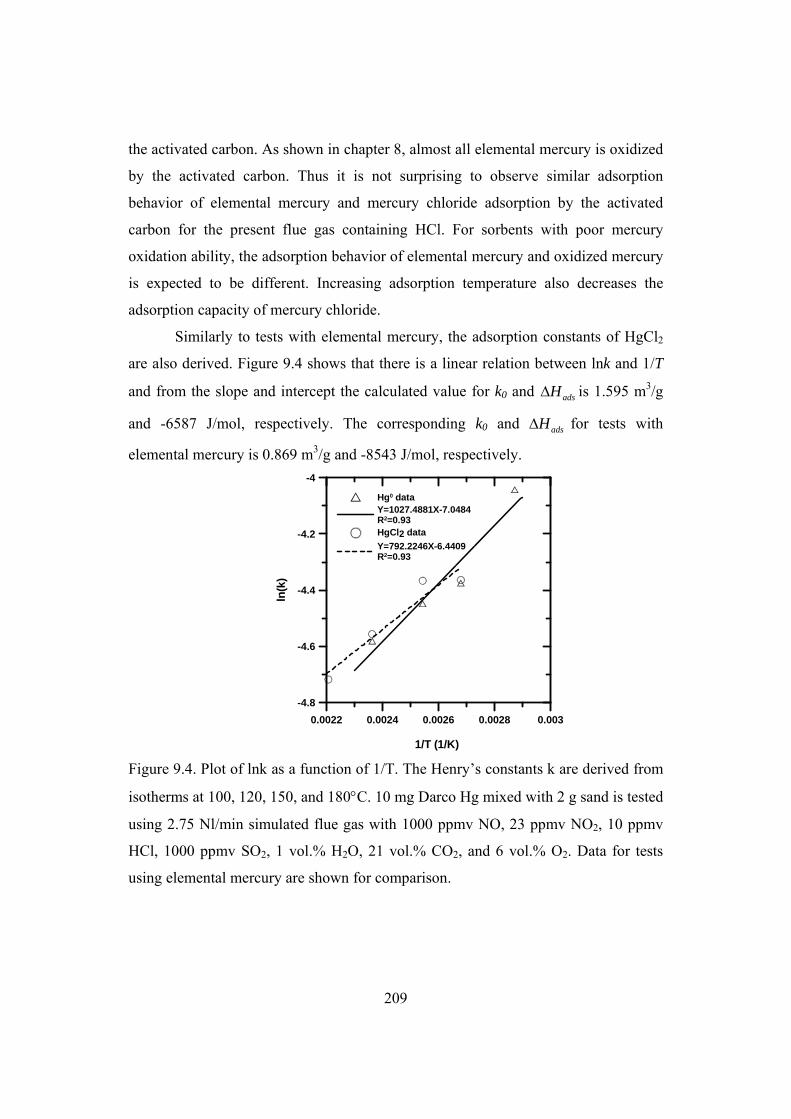
209
the activated carbon. As shown in chapter 8, almost all elemental mercury is oxidized
by the activated carbon. Thus it is not surprising to observe similar adsorption
behavior of elemental mercury and mercury chloride adsorption by the activated
carbon for the present flue gas containing HCl. For sorbents with poor mercury
oxidation ability, the adsorption behavior of elemental mercury and oxidized mercury
is expected to be different. Increasing adsorption temperature also decreases the
adsorption capacity of mercury chloride.
Similarly to tests with elemental mercury, the adsorption constants of HgCl2
are also derived. Figure 9.4 shows that there is a linear relation between lnk and 1/T
and from the slope and intercept the calculated value for k0 and adsH is 1.595 m3/g
and -6587 J/mol, respectively. The corresponding k0 and adsH for tests with
elemental mercury is 0.869 m3/g and -8543 J/mol, respectively.
0.0022 0.0024 0.0026 0.0028 0.003
1/T (1/K)
-4.8
-4.6
-4.4
-4.2
-4
ln(k
)
Hg0 dataY=1027.4881X-7.0484R2=0.93HgCl2 data
Y=792.2246X-6.4409R2=0.93
Figure 9.4. Plot of lnk as a function of 1/T. The Henry’s constants k are derived from
isotherms at 100, 120, 150, and 180C. 10 mg Darco Hg mixed with 2 g sand is tested
using 2.75 Nl/min simulated flue gas with 1000 ppmv NO, 23 ppmv NO2, 10 ppmv
HCl, 1000 ppmv SO2, 1 vol.% H2O, 21 vol.% CO2, and 6 vol.% O2. Data for tests
using elemental mercury are shown for comparison.

210
9.3 Effect of flue gas composition
Since negligible effects of CO2, O2, CO, and NO on elemental mercury
adsorption by the activated carbon are observed and preliminary tests of mercury
chloride adsorption by the activated carbon shows similar behavior as elemental
mercury, only effects of H2O, SO2, HCl, and NO2 on mercury chloride adsorption by
the Darco Hg activated carbon are investigated. The effects of H2O, SO2, HCl, and
NO2 on equilibrium adsorption capacity of mercury chloride are presented in figure
9.5-8, respectively. Data for tests using elemental mercury are shown for comparison.
0 5 10 15 20 25 30
H2O level in gas (%)
0
0.2
0.4
0.6
0.8
1
1.2
1.4
Mer
cury
ad
sorp
tio
n c
apac
ity
(g
_Hg
/mg
_car
bo
n)
Data,Hg0
Y=1.1277X-0.261
R2=0.98Data, HgCl2
Y=1.2389X-0.240
R2=0.98
Figure 9.5. Effects of water in the flue gas on mercury chloride adsorption capacity of
10 mg Darco Hg carbon mixed with 2 g sand tested at 150C using 2.75 Nl/min
simulated flue gas with 1000 ppmv NO, 23 ppmv NO2, 1000 ppmv SO2, 10 ppmv
HCl, 6 vol.% O2, and 21 vol.% CO2.

211
0 200 400 600 800 1000 1200
SO2 level in gas (ppmv)
0
1
2
3
4
5
Mer
cury
ad
sorp
tio
n c
apac
ity
(g
_Hg
/mg
_car
bo
n)
Data,Hg0
Y=69.176X-0.592
R2=0.99Data,HgCl2
Y=58.23X-0.565
R2=0.99
Figure 9.6. Effects of SO2 in the flue gas on mercury chloride adsorption capacity of
10 mg Darco Hg carbon mixed with 2 g sand tested at 150C using 2.75 Nl/min
simulated flue gas with 1000 ppmv NO, 23 ppmv NO2, 10 ppmv HCl, 6 vol.% O2, 1
vol.% H2O, and 21 vol.% CO2.
0 4 8 12 16 20 24
HCl level in gas (ppmv)
0
0.2
0.4
0.6
0.8
1
1.2
1.4
1.6
Mer
cury
ad
sorp
tio
n c
apac
ity
(g
_Hg
/mg
_car
bo
n)
Data,Hg0
Y=0.9728X0.071
R2=0.82Data,HgCl2Y=0.9162X0.1158
R2=0.76
Figure 9.7. Effects of HCl in the flue gas on mercury chloride adsorption capacity of
10 mg Darco Hg carbon mixed with 2 g sand tested at 150C using 2.75 Nl/min
simulated flue gas with 1000 ppmv NO, 23 ppmv NO2, 1000 ppmv SO2, 6 vol.% O2,
1 vol.% H2O, and 21 vol.% CO2.

212
0 20 40 60 80 100 120
NO2 level in gas (ppmv)
0
0.2
0.4
0.6
0.8
1
1.2
1.4
1.6
Mer
cury
ad
sorp
tio
n c
apac
ity
(g
_Hg
/mg
_car
bo
n)
Data, Hg0
Y=2.0685X-0.199
R2=0.89Data, HgCl2
Y=2.0732X-0.197
R2=0.88
Figure 9.8. Effects of NO2 in the flue gas on mercury chloride adsorption capacity of
10 mg Darco Hg carbon mixed with 2 g sand tested at 150C using 2.75 Nl/min
simulated flue gas with 1000 ppmv NO, 1000 ppmv SO2, 10 ppmv HCl, 6 vol.% O2,
1 vol.% H2O, and 21 vol.% CO2.
The adsorption capacity of mercury chloride is slightly larger than the
elemental mercury when the water content in the flue gas is above 1 vol.%. Almost
the same tendency of adsorption capacity as a function of SO2, HCl, and NO2
concentration in the flue gas is observed for mercury chloride and elemental mercury.
This is again due to the high oxidation rate of elemental mercury by the Darco Hg
carbon.
9.4 Conclusions
Similar adsorption behaviors of mercury chloride and elemental mercury by
Darco Hg activated carbon are observed using simulated cement kiln flue gas at
different temperatures. Increasing adsorption temperature also decreases the
adsorption capacity of mercury chloride.
The effects of H2O, SO2, HCl, and NO2 on mercury chloride adsorption by
Darco Hg are investigated by varying their concentrations in the baseline gas.
Compared to elemental mercury adsorption, a slightly larger adsorption capacity of
mercury chloride is obtained when the water content in the flue gas is above 1 vol.%.

213
The dependence of mercury chloride adsorption capacity on SO2, HCl, and NO2
concentrations in the flue gas is the same as elemental mercury adsorption capacity.
The similar behavior of mercury chloride and elemental mercury is due to the
effective catalytic oxidation of elemental mercury by the activated carbon in the
presence of HCl.
9.5 References
[1] H.C. Hsi, S. Chen, M. Rostam-Abadi, M.J. Rood, C.F. Richardson, T.R. Carey, R. Chang,
Preparation and evaluation of coal-derived activated carbons for removal of mercury vapor
from simulated coal combustion flue gases, Energy & Fuels. 12 (1998) 1061-1070.
[2] M. Rostam-Abadi, S.G. Chen, H.C. Hsi, M. Rood, R. Chang, T.R. Carey, B., Hargrove, C.
Richardson, W. Rosenhoover, F. Meserole, Novel vapor phase mercury sorbents,
Proceedings of the EPRI-DOE-EPA Combined Utility Air Pollutant Control, Washington,
DC, Aug 25–29, 1997.
[3] T.R. Carey, O.W. Hargrove Jr, C.F. Richardson, R. Chang and F.B. Meserole, Factors
affecting mercury control in utility flue gas using sorbent injection, Proceedings of the Air &
Waste Management Association's 90th Annual Meeting, Toronto, Ontario, Canada, June 8-13,
1997.
[4] C.X. Hu, J.S. Zhou, Z.Y. Luo, S. He, G.K. Wang, K.F. Cen, Effect of oxidation treatment
on the adsorption and the stability of mercury on activated carbon, Journal of Environmental
Sciences-China. 18 (2006) 1161-1166.
[5] B. Ghorishi and B.K. Gullett, Fixed-bed control of mercury: Role of acid gases and a
comparison between carbon-based, calcium-based, and coal fly ash sorbents, Proceedings of
the EPRI/DOE/EPA Combined Utility Air Pollutant Control Symposium, Washington, DC,
August 25–29, 1997.
[6] S.B. Ghorishi and C.B. Sedman, Combined mercury and sulfur oxides control using
calcium-based sorbents, Proceedings of the EPRI-DOE-EPA Combined Utility Air Pollutant
Control Symposium, Washington, DC, August 25–29, 1997.
[7] S.B. Ghorishi and B.K. Gullett, An experimental study on mercury sorption by activated
carbons and calcium hydroxide, The Fifth Annual North American Waste-to-Energy
Conference, Research Triangle Park, NC, 22-25 April, 1997.
[8] N. Hutson, C. Singer, C. Richardson, J. Karwowski and C. Sedman, Practical applications
from observations of mercury oxidation and binding mechanisms, EPRI-DOE-EPA-AWMA
Combined Power Plant Air Pollutant Control Mega Symposium, Washington DC, August 30
- September 2, 2004.
[9] E.J. Granite, M.C. Freeman, R.A. Hargis, W.J. O'Dowd, H.W. Pennline, The thief process
for mercury removal from flue gas, J. Environ. Manage. 84 (2007) 628-634.

214
[10] W.J. O’Dowd, H.W. Pennline, M.C. Freeman, E.J. Granite, R.A. Hargis, C.J. Lacher, A.
Karash, A technique to control mercury from flue gas: The thief process, Fuel Processing
Technology. 87 (2006) 1071-1084.
[11] R. Bhardwaj. Impact of temperature and flue gas components on mercury speciation and
uptake by activated carbon sorbents . Master thesis. Master, University of Pittsburgh, 2007.
[12] M.M. Maroto-Valer, Y. Zhang, E.J. Granite, Z. Tang, H.W. Pennline, Effect of porous
structure and surface functionality on the mercury capacity of a fly ash carbon and its
activated sample, Fuel. 84 (2005) 105-108.
[13] S. Eswaran, H.G. Stenger, Z. Fan, Gas-phase mercury adsorption rate studies, Energy &
Fuels. 21 (2007) 852-857.
[14] T.R. Carey, O.W. Hargrove Jr, C.F. Richardson, R. Chang, F.B. Meserole, Factors
affecting mercury control in utility flue gas using activated carbon, Journal of the Air &
Waste Management Association. 48 (1998) 1166.
[15] T.R. Carey, C.F. Richardson, R. Chang, F.B. Meserole, M. Rostam-Abadi, S. Chen,
Assessing sorbent injection mercury control effectiveness in flue gas streams, Environ. Prog.
19 (2000) 167-174.
[16] B.A.F. Mibeck, E.S. Olson, S.J. Miller, HgCl2 sorption on lignite activated carbon:
Analysis of fixed-bed results, Fuel Process Technol. 90 (2009) 1364-1371.

215
10
Simulation of mercury adsorption by fixed
carbon bed
To properly understand an adsorption process, two basic ingredients, i.e.,
equilibrium and transport processes must be investigated. Understanding of the
adsorptive capacity is within the domain of equilibrium, and understanding of the
diffusion resistance is within the domain of transport process. These two aspects are
first introduced in this chapter. The remaining part of this chapter deals with
mathematical models describing the behavior of isothermal adsorption of mercury in
a carbon particle and a fixed carbon bed including adsorption isotherm, mass balance
for the gas phase and mass balance inside the adsorbent.
10.1 Adsorption equilibrium
A summary of commonly used isotherm equations for pure gas adsorption is
given in the following table 10.1. Considering the typical mercury level in the flue
gas of ppb level, the simple Henry’s law is able to describe the isotherm well, as
shown in chapter 8.

216
Table 10.1. Summary of commonly used isotherm equations for pure gas adsorption
[1].
Isotherm Equation Remarks Henry law C KC Low pressure range
Langmuir
1s
bCC C
bC
Has Henry law limit and finite saturation limit
Frendlich 1/nFC K C Does not have Henry law
limit and no saturation limit Langmuir-Frendlich 1/
1/
( )
1 ( )
n
s n
bCC C
bC
Does not have Henry law limit, but has finite saturation limit
Toth 1/[1 ( ) ]s t t
bCC C
bC
Has Henry law limit and finite saturation limit
Unilan 1( )
2 1
ss
s
C be CC ln
s be C
Has Henry law limit and finite saturation limit
K: Henry constant; C: gaseous adsorbate concentration; C: adsorbed concentration in
the sorbent; Cs: saturation adsorbed concentration in the sorbent; b: Langmuir
constant; KF: Frendlich constant; s: heterogeneity parameter
10.2 Transport consideration in adsorption process
Adsorption of an adsorbate molecule on to the porous surface of an adsorbent
include following steps [2]:
1. External (or interphase) mass transfer of the adsorbate from the bulk fluid by
convection through a thin film or boundary layer.
2. Internal (intraphase) mass transfer of the adsorbate by pore diffusion from the
outer surface of the adsorbent to the inner surface of the internal porous structure.
3. Surface diffusion along the porous surface.
4. Adsorption of the adsorbate onto the porous surface.
10.2.1 External transport
Rates of convection mass and heat transfer between the outer surface of a
particle and the surrounding bulk fluid during an adsorption process are given,
respectively, by [2]:
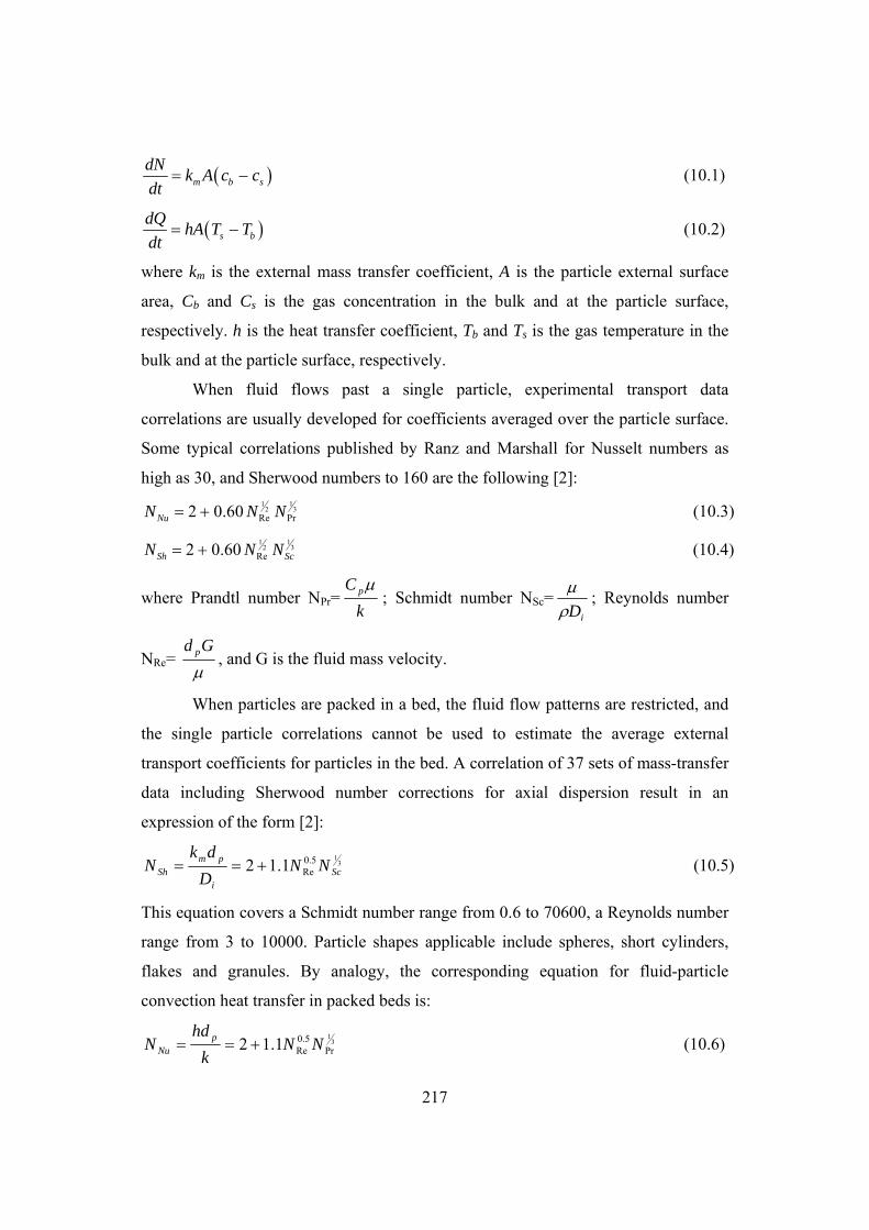
217
m b s
dNk A c c
dt (10.1)
s b
dQhA T T
dt (10.2)
where km is the external mass transfer coefficient, A is the particle external surface
area, Cb and Cs is the gas concentration in the bulk and at the particle surface,
respectively. h is the heat transfer coefficient, Tb and Ts is the gas temperature in the
bulk and at the particle surface, respectively.
When fluid flows past a single particle, experimental transport data
correlations are usually developed for coefficients averaged over the particle surface.
Some typical correlations published by Ranz and Marshall for Nusselt numbers as
high as 30, and Sherwood numbers to 160 are the following [2]: 11
32Re Pr2 0.60NuN N N (10.3)
1132
Re2 0.60Sh ScN N N (10.4)
where Prandtl number NPr=k
C p ; Schmidt number NSc=iD
; Reynolds number
NRe= Gd p , and G is the fluid mass velocity.
When particles are packed in a bed, the fluid flow patterns are restricted, and
the single particle correlations cannot be used to estimate the average external
transport coefficients for particles in the bed. A correlation of 37 sets of mass-transfer
data including Sherwood number corrections for axial dispersion result in an
expression of the form [2]:
315.0
Re1.12 Sci
pmSh NN
D
dkN (10.5)
This equation covers a Schmidt number range from 0.6 to 70600, a Reynolds number
range from 3 to 10000. Particle shapes applicable include spheres, short cylinders,
flakes and granules. By analogy, the corresponding equation for fluid-particle
convection heat transfer in packed beds is:
31
Pr5.0
Re1.12 NNk
hdN p
Nu (10.6)

218
When these equations are used with beds packed with non-spherical particles, dp, is
the equivalent diameter of a spherical particle.
10.2.2 Internal transport
Porous particles in most cases have a sufficiently high effective thermal
conductivity so that temperature gradients within the particle are negligible. In
contrast, internal mass transfer within the particle must be considered. In sorption
processes, transport is from the exterior to the interior for adsorption and from the
interior to the exterior for desorption processes. The flux of mercury transported to
the carbon particle can be expressed as:
dr
dCDN eA (10.7)
where De is the effective diffusion coefficient. There are basically three modes of
transport of molecules inside a porous medium: Knudsen diffusion, molecular
diffusion, and surface diffusion [1].
10.2.2.1 Molecular Diffusion
When the adsorbate is in a macropore or in the fluid phase, the frequency of
collision with a surface is minimal and transport of the molecule occurs via
intermolecular collisions only. This mode of transport is due to a partial pressure
gradient of a continuum fluid mixture.
For binary gas mixtures at low pressure (<10 atm), the diffusion coefficient is
inversely proportional to the pressure, increases with increasing temperature and is
almost independent of composition for a given gas pair. For nonpolar gases the
prediction of the Chapman-Enskog kinetic theory is usually preferred for diffusion
coefficient calculation [1]:
(10.8)
where DAB is in cm2/s, T in K, P in atm, MW in g/mol. AB and D,AB are
characteristic molecular properties that are based on the Lennard-Jones potential
3 1 1
2,
( )0.0018583 A BMW MW
ABAB D AB
TD
P

219
parameters of the individual species in the system. MWA and MWB are molecular
weights of species A and B. The molecular collision diameter, AB, is calculated as
the arithmetic average of the two species:
12 ( )AB A B (10.9)
D,AB is a dimensionless function of temperature and the intermolecular potential
field for a molecular of A and B. The interaction is described by the individual
Lennard-Jones 12-6-potentials, A and B, in accordance with following equation:
.AB A Bk k k
(10.10)
D,AB can be calculated according to:
, 0.15610
1.06036 0.19300 1.03587 1.76474
( ) exp(0.47635 ) exp(1.52996 ) exp(3.89411 )D AB
AB AB AB AB
kT kT kT kT
(10.11)
where k is the Boltzmann’s constant.
The Lennard-Jones potential parameter for N2 can be easily found while for
elemental mercury only few data are available. Table 10.2 lists the Lennard-Jones
potential parameter for N2 and elemental mercury.
Table 10.2. Lennard-Jones potential parameter for N2 and elemental mercury [3].
(Å) /k (K) N2 3.681 91.5 Hg 3.23 627
10.2.2.2 Knudsen Diffusion
This diffusion process occurs when the mean free path of the adsorbate is
much larger than the diameter of the channel in which the diffusing molecules reside.
This normally occurs at very low pressure and channels of small size, usually of order
of 10 nm to 100 nm [1]. The flow is induced by collision of gaseous molecules with
the pore wall.
829700
3g
K
R Tr TD r
MW MW (10.12)
where r is the pore radius in cm, T in K, MW in g/mol, Dk, in cm2/s.

220
10.2.2.3 Surface Diffusion
In most cases, the surface diffusion coefficient is unknown as the heat of
adsorption is not available. Furthermore, the surface diffusivity is a strong function of
the amount of mercury adsorbed and the sorbent surface coverage is low due to the
low mercury level in the flue gas, it is therefore reasonable to assume that the surface
diffusion resistance can be neglected.
10.3 Modeling of adsorption in a single particle
The final aim of this project is to develop a mathematical model that can
simulate mercury adsorption by a carbon cake on the fabric filter bags. A single
particle model is the core and starting points of the filter model. The single particle
model can be used to study how an adsorption process would vary with parameters
such as particle size, bulk concentration, pressure, temperature, pore size, and
adsorption affinity. Analytical solution of the single particle model is available when
linear adsorption isotherm is used. However, the single particle model works only at
constant gas atmosphere. The gas concentration changes in time for both the fixed-
bed and fabric filter adsorption processes. Therefore a numerical solution of the
single particle model is required in order to incorporate it to fixed-bed and fabric
filter models.
Do [1] has made a detailed description of the single particle adsorption model
using linear isotherm. Both analytical solution and numerical solution using
orthogonal collocation method with subroutines in MATLAB are provided in his
book. Fixed-bed and fabric filter models in this work are further developed on the
basis of the single particle model.
Since the mercury level in the flue gas is very low, the adsorption system can
be treated as isothermal. Mass balance around a thin shell element in the particle
gives [1]:
1(1 ) ( )s
p p e s
CC CD r
t t r r r
(10.13)

221
where p is the porosity of the particle, C is gaseous mercury concentration, C is the
mercury concentration in the adsorbed phase, De is the pore diffusivity, and s is the
particle shape factor (s=0, 1, and 2 for slab, cylinder, and sphere, respectively).
The free molecules of mercury in the pore space and the adsorbed mercury
molecules at any point within a particle are assumed in equilibrium with each other.
The local linear isotherm takes the form:
C KC (10.14)
where K is the Henry constant.
Substituting the local equilibrium into the mass balance equation, we can
obtain [1]:
2 1( )
(1 )se
app sp p
DC CD C r
t K r r r
(10.15)
with initial condition: t=0, C=Ci, (10.16)
and typical boundary conditions:
0, 0C
rr
(10.17)
, ( )p
p e m bRr R
Cr R D k C C
r
(10.18)
For slab object R is the half thickness, while for cylindrical and spherical objects, R is
their respective radius. Cb is the concentration of the adsorbate in the bulk
surrounding the particle, km is the external mass transfer coefficient.
An analytical solution of the concentration distribution within the particle is
given in the form of an infinite series [1]. The solution is only valid for a particle
surrounded by a gas atmosphere not changing in time. To get a numerical solution,
equation 10.15 is written in a dimensionless form by defining following non-
dimensional variables and parameters:
20 0 0
; ; ; ;app b ib i
p p
D t C CC ry x y y
C R R C C
1( )s
s
y yx
x x x
(10.19)
Initial condition: =0, y=yi (10.20)

222
Boundary conditions:
0, 0y
xx
(10.21)
)(;1 yyBix
yx b
(10.22)
where Bi is the Biot number epm DRk .
The problem has symmetry at x=0, and it is useful to utilize this by making
the transformation of u=x2, and the differential equation becomes [1]:
2
24 2( 1)
y y yu s
u u
(10.23)
The equation is solved by the orthogonal collocation method [4]. The domain u(0,1)
is represented by n interior collocation points. Taking the boundary point (u=1) as the
(n+1)-th point, we have a total of n+1 interpolation points. The first and second
derivatives at these interpolation points are related to the functional values at all
points as given below:
1n
ij jji
yA y
u
(10.24)
2 1
2
n
ij jji
yB y
u
(10.25)
The matrices A and B are constant matrices once n+1 interpolation points have been
chosen. The mass balance equation is valid at any point within the u domain.
Evaluating the equation at the ith interior collocation point we get:
1
1
ni
ij jj
yC y
(10.26)
For i=1, 2,…n, where
4 2(1 )ij i ij ijC u B s A (10.27)
Numerical calculation of the average gaseous mercury concentration inside the
particle is obtained by:
1
0
1( ) ( , ) ( 1) ( , ) s
V
C t C t x dV s C t x x dsV
(10.28)

223
1 1
2
0
( 1)( ) ( , )
2
ssC t C t x u du
(10.29)
The integration is evaluated by Radau quadrature [1,4]:
1 11 1
2
10 0
1( , ) (1 ) ( , ) ; 0;
2
s n
k kk
sC t x u du u u C t x du w C
(10.30)
where the weight factors wk are the Radau quadrature weights.
The calculated Radau quadratue weights from the program are normalized [4]:
( , )k
k
wW
I (10.31)
( , ) ( 1) ( 1) 2 10
( 2) 1 2
sI for and
s
(10.32)
2
1k kw Ws
(10.33)
1 1 12
10
( 1)( ) ( , )
2
s n
k kk
sC t C t x u du W C
(10.34)
The boundary condition at the particle surface becomes:
1; ( )2 b
y Biu y y
u
(10.35)
1
1, 11
( )2
N
n j j b nj
BiA y y y
(10.36)
From which we can solve for the concentration at the boundary in terms of other
dependent variables [1]:
1,1
1
1, 1
2
21
n
b n j jj
n
n n
y A yBi
yA
Bi
(10.37)
The mass balance equation together with initial and boundary conditions are solved
numerically by combination of collocation and Runge-Kutta methods using
MATLAB [1]. Both the analytical solution and numerical solution give the same
results for the single particle adsorption model using local linear isotherm [1].
The developed model is used to simulate mercury adsorption by a single
Darco Hg activated carbon particle exposed to elemental mercury at 150C in
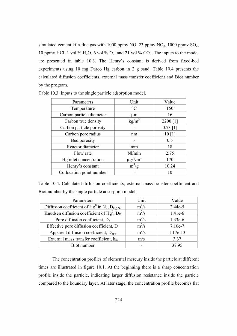
224
simulated cement kiln flue gas with 1000 ppmv NO, 23 ppmv NO2, 1000 ppmv SO2,
10 ppmv HCl, 1 vol.% H2O, 6 vol.% O2, and 21 vol.% CO2. The inputs to the model
are presented in table 10.3. The Henry’s constant is derived from fixed-bed
experiments using 10 mg Darco Hg carbon in 2 g sand. Table 10.4 presents the
calculated diffusion coefficients, external mass transfer coefficient and Biot number
by the program.
Table 10.3. Inputs to the single particle adsorption model.
Parameters Unit Value Temperature C 150
Carbon particle diameter µm 16 Carbon true density kg/m3 2200 [1]
Carbon particle porosity - 0.73 [1] Carbon pore radius nm 10 [1]
Bed porosity - 0.5 Reactor diameter mm 18
Flow rate Nl/min 2.75 Hg inlet concentration µg/Nm3 170
Henry’s constant m3/g 10.24 Collocation point number - 10
Table 10.4. Calculated diffusion coefficients, external mass transfer coefficient and
Biot number by the single particle adsorption model.
Parameters Unit Value Diffusion coefficient of Hg0 in N2, DHg,N2 m2/s 2.44e-5 Knudsen diffusion coefficient of Hg0, DK m2/s 1.41e-6
Pore diffusion coefficient, Dp m2/s 1.33e-6 Effective pore diffusion coefficient, De m2/s 7.10e-7
Apparent diffusion coefficient, Dapp m2/s 1.17e-13 External mass transfer coefficient, km m/s 3.37
Biot number - 37.95
The concentration profiles of elemental mercury inside the particle at different
times are illustrated in figure 10.1. At the beginning there is a sharp concentration
profile inside the particle, indicating larger diffusion resistance inside the particle
compared to the boundary layer. At later stage, the concentration profile becomes flat

225
until the mercury concentration reaches the bulk level at all positions inside the
particle when the adsorption equilibrium is obtained.
Figure 10.1. Simulated mercury concentration profile inside the particle at different
time. The corresponding time for each curve from bottom to top is 0.06, 0.29, 0.77,
2.20, 5.40, 14.04, 33.84, 94.32, 323.64, 1425.24, 3600 s, respectively. Inputs to the
model are given in table 10.3.
The amount of elemental mercury adsorbed as a function of time for different
particle sizes is illustrated in figure 10.2. The calculated external mass transfer
coefficient, Biot number, and time for equilibrium adsorption are given in the table
10.5. The larger the particle is, the larger the Biot numbers are. This indicates that the
larger particle has larger internal mass transfer resistance. As a result, it takes the
larger particle longer time to reach the equilibrium. For a 16 µm particle it takes 7.2
min to reach the equilibrium, while for a 100 µm particle it takes more than four
hours.

226
Figure 10.2. Simulated amount of mercury adsorbed in the Darco Hg carbon particle
as a function of time for particles with different diameters.
Table 10.5. Calculated external mass transfer coefficient, Biot number, and simulated
equilibrium approach time for Darco Hg carbon with different particle sizes.
d=5 m d=16 m d=50 m d=100 m d=200 m d=300 m External
mass transfer coefficient,
km (m/s)
10.26 3.37 1.18 0.64 0.36 0.26
Biot number 36.14 37.95 41.48 45.15 50.73 55.24 99%
equilibrium approach time (h)
0.01 0.12 0.89 4.28 17.04 36.41
10.4 Fixed bed adsorption model
In this project a plug flow model with linear equilibrium isotherm, external
and intraparticle mass transfer resistances is developed. Due to the low level of

227
mercury applied in this project the system can be treated as isothermal. The plug-flow
model means that the fluid velocity profile is uniform at all radial positions, a fact
which generally involves turbulent flow conditions. In addition, it is assumed that the
fixed-bed adsorption reactor is packed randomly with adsorbent particles. The
adsorption process is supposed to be very fast relative to the convection and diffusion
effects; subsequently, local equilibrium will exist inside the adsorbent particles [5].
If the solid particles are small, the axial diffusion effects can be ignored and
the main mode of transport in the mobile fluid phase is by convection [6]. Consider a
section of the fixed bed column with a length of z, cross section area of A, and bed
porosity of b, as shown in figure 10.3, a mass balance of the mercury contained in
both phase, we get [6]:
t
qzA
t
CzAtzzACvtzACv bb
)1(),(),( 00 (10.38)
where v0 is the superficial fluid velocity. Dividing through by Az and taking limit,
we get the overall balance of the mercury [6]:
0 (1 ) 0b b
C C qv
z t t
(10.39)
q is the volume-average mercury loading per unit volume of porous pellet,
Figure 10.3. Sketch of a fixed-bed absorber.
Using the void velocity u, we get:
10b
b
C C qu
z t t
(10.40)

228
q can be expressed as [2]:
23
0
3 PR
P
q r qdrR
(10.41)
where Rp is the radius of the carbon particle.
Equation 10.40 gives the concentration of the mercury in the bulk gas as a
function of time and location in the bed. The concentration of mercury in the gas
within the pores of a carbon particle is obtained by solving equation 10.13.
The simultaneous solution of equation 10.13 and10.41 is a hard task, which
can be avoided by using the tank-in-series method. The fixed-bed is divided into N
equal size well-mixed tanks and the mercury mass balance in the bulk gas phase for
each tank can be written as:
(10.42)
where Vi is the volume of each tank, F is the flow rate through the bed, Cbin,i and Cb,i
is the inlet and outlet mercury concentration in tank i, respectively, Np is the particle
number in tank i, As is the outer surface area of one particle, Cs,i is the gaseous
mercury concentration at the particle surface in tank i. Giving the bed cross area A,
bed height h, total mass of sorbent in the bed M, void velocity u, particle radius Rp,
and density p, the above equation can be expressed as:
(10.43)
Further arranging equation 10.43 into:
,, , , ,
3( ) ( )
(1 )b i m
bin i b i b i s ib p p p
dC MkuNC C C C
dt h R Ah
(10.44)
Initial condition:
t=0, C=0, Cbin,i=Cb0, all tanks (10.45)
t>0 Cbin= Cb0, tank 1 (10.46)
Boundary conditions:
0, 0C
rr
(10.47)
,, ( )e m b iRr R
Cr R D k C C
r
(10.48)
,, , , ,( )b i
b i bin i b i m p s b i s i
dCV FC FC k N A C C
dt
,, , , ,
3( ) ( )
(1 )b i
b b bin i b i m b i s ip p p
dCAh Mu A C C k C C
N dt NR
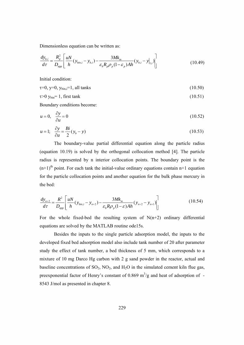
229
Dimensionless equation can be written as:
(10.49)
Initial condition:
=0, y=0, ybin,i=1, all tanks (10.50)
>0 ybin= 1, first tank (10.51)
Boundary conditions become:
0, 0y
uu
(10.52)
1; ( )2 b
y Biu y y
u
(10.53)
The boundary-value partial differential equation along the particle radius
(equation 10.19) is solved by the orthogonal collocation method [4]. The particle
radius is represented by n interior collocation points. The boundary point is the
(n+1)th point. For each tank the initial-value ordinary equations contain n+1 equation
for the particle collocation points and another equation for the bulk phase mercury in
the bed:
(10.54)
For the whole fixed-bed the resulting system of N(n+2) ordinary differential
equations are solved by the MATLAB routine ode15s.
Besides the inputs to the single particle adsorption model, the inputs to the
developed fixed bed adsorption model also include tank number of 20 after parameter
study the effect of tank number, a bed thickness of 5 mm, which corresponds to a
mixture of 10 mg Darco Hg carbon with 2 g sand powder in the reactor, actual and
baseline concentrations of SO2, NO2, and H2O in the simulated cement kiln flue gas,
preexponential factor of Henry’s constant of 0.869 m3/g and heat of adsorption of -
8543 J/mol as presented in chapter 8.
2,
, , , 1,
3( ) ( )
(1 )pb i m
bin i b i b i iapp b p p p
Rdy MkuNy y y y
d D h R Ah
22
, 2 2 1
3( ) ( )
(1 )n m
bin i n n napp b p
dy MkR uNy y y y
d D h R Ah

230
A parameter study of the model was first conducted to evaluate the effect of
collocation point number inside the carbon particle and tank number on the mercury
breakthrough curve of the carbon bed. Figure 10.4 illustrates the effects of collocation
point number inside the carbon particle on the mercury breakthrough curve of 10 mg
Darco Hg carbon tested at 75C with 90 µg/Nm3 mercury in the simulated cement
kiln flue gas. Reasonable agreement between the simulation and experimental data is
already obtained using one collocation point inside the carbon particle. Simulations
using 2, 5, and 10 collocation points generate the same mercury breakthrough curve.
Generally more accurate solutions can be obtained using more collocation points.
Since the simulation can be done within 30 s, a collocation point of 10 is used as
default input to the program.
Figure 10.4. Effects of collocation point number inside the carbon particle on the
simulated mercury breakthrough curves of 10 mg Darco Hg mixed with 2 g sand
tested at 75C using 2.75 Nl/min simulated flue gas with 90 µg Hg0/Nm3, 10 ppmv
HCl, 1000 ppmv NO, 1000 ppmv SO2, 23 ppmv NO2, 1 vol.% H2O, 6 vol.% O2, and
21 vol.% CO2. A tank number of 20 is applied in the simulation.

231
Figure 10.5 presents the effects of applied tank number in the simulation on
the predicted mercury breakthrough curve of 10 mg Darco Hg carbon tested at 75C
with 90 µg/Nm3 mercury in the simulated cement kiln flue gas. Better agreement
between the simulation and experimental data is obtained when larger tank number is
applied. When the tank number is above 20, the produced breakthrough profile is
almost the same.
Figure 10.5. Effects of applied tank number on the simulated mercury breakthrough
curves of 10 mg Darco Hg mixed with 2 g sand tested at 75C using 2.75 Nl/min
simulated flue gas with 90 µg Hg0/Nm3, 10 ppmv HCl, 1000 ppmv NO, 1000 ppmv
SO2, 23 ppmv NO2, 1 vol.% H2O, 6 vol.% O2, and 21 vol.% CO2. A collocation point
number of 10 inside the carbon particle is applied in the simulation.
Validation and parametric study of mercury adsorption by the activated
carbon is conducted by simulation and comparison with the experimental data as
shown in figure 10.6-10.12. The developed fixed bed model can reasonably simulate
the effects of temperature, mercury inlet concentration, flow gas rate, carbon particle
size, and SO2, H2O, NO2 level in the flue gas on the mercury breakthrough curve of
fixed bed with 10 mg carbon in 2g sand powder. Isotherm study of crushed Norit

232
RB4 pellets is not performed and the Henry’s constant for Norit RB4 carbon is
calculated by comparing the equilibrium adsorption capacity with Darco Hg carbon at
the same conditions.
Figure 10.6. Comparison of simulation and experimental data for effect of adsorption
temperature on mercury breakthrough of 10 mg Darco Hg mixed with 2 g sand using
2.75 Nl/min simulated flue gas with 90 µg Hg0/Nm3,1000 ppmv NO, 23 ppmv NO2,
10 ppmv HCl, 1000 ppmv SO2, 1 vol.% H2O, 21 vol.% CO2, and 6 vol.% O2.
The model can clearly simulate the effect of adsorption temperature on
mercury breakthrough curve of the carbon bed, i.e., faster mercury breakthrough is
obtained at higher adsorption temperature. The Henry constants at each temperature
are calculated from the derived preexponential factor and heat of adsorption. The best
agreement between the simulation and experimental data is obtained for adsorption
test at 75C as shown in figure 10.6.

233
Figure 10.7. Comparison of simulation and experimental data for effect of elemental
mercury inlet level on mercury breakthrough of 10 mg Darco Hg mixed with 2 g sand
tested at 120C using 2.75 Nl/min simulated flue gas with 1000 ppmv NO, 23 ppmv
NO2, 10 ppmv HCl, 1000 ppmv SO2, 1 vol.% H2O, 21 vol.% CO2, and 6 vol.% O2.
Figure 10.7 shows that the best agreement between the simulation and
experimental data regarding the effects of mercury inlet level is the mercury
breakthrough curve of 57 µg/Nm3 mercury level. The simulation slightly overpredicts
the mercury adsorption with 95 µg/Nm3 and underpredicts the mercury adsorption for
tests with 27 µg/Nm3 in the flue gas. When taking the experimental uncertainty into
account, the simulation is acceptable as the average uncertainty of the equilibrium
mercury adsorption capacity is about ±10%.

234
Figure 10.8. Comparison of simulation and experimental data for effect of flue gas
flow rate on mercury breakthrough of 10 mg Darco Hg mixed with 2 g sand tested at
150C using 2.75 Nl/min simulated flue gas with 160-170 µg Hg0/Nm3, 1000 ppmv
NO, 23 ppmv NO2, 10 ppmv HCl, 1000 ppmv SO2, 1 vol.% H2O, 21 vol.% CO2, and
6 vol.% O2.
Figure 10.8 illustrates that there are good agreements between the simulations
and experimental data regarding the initial mercury breakthrough time when the
mercury concentration after the carbon bed starts to increase and the model correctly
predicts that. The model overpredicts the effect of changing gas flow especially for
high flow rates.

235
Figure 10.9. Comparison of simulation and experimental data for effect of particle
size on mercury breakthrough for 10 mg crushed Norit RB4 pellets in 2 g sand tested
at 150C using 2.75 Nl/min simulated flue gas with 160-170 µg Hg0/Nm3, 1000 ppmv
NO, 23 ppmv NO2, 10 ppmv HCl, 1000 ppmv SO2, 1 vol.% H2O, 21 vol.% CO2, and
6 vol.% O2.
There are good agreements between the simulations and experimental data for
the effect of particle size for Norit RB4 over the size range of 38-325 µm, as
illustrated in figure 10.9.

236
Figure 10.10. Comparison of simulation and experimental data for effect of SO2
concentration in the flue gas on mercury breakthrough profile of 10 mg Darco Hg
mixed with 2 g sand tested at 150C using 2.75 Nl/min simulated flue gas with 160-
170 µg Hg0/Nm3, 1000 ppmv NO, 23 ppmv NO2, 10 ppmv HCl, 1 vol.% H2O, 6
vol.% O2, and 21 vol.% CO2.

237
Figure 10.11. Comparison of simulation and experimental data for effect of water
concentration in the flue gas on mercury breakthrough profile of 10 mg Darco Hg
mixed with 2 g sand tested at 150C using 2.75 Nl/min simulated flue gas with 160-
170 µg Hg0/Nm3, 1000 ppmv NO, 23 ppmv NO2, 10 ppmv HCl, 1000 ppmv SO2, 6
vol.% O2, and 21 vol.% CO2.

238
Figure 10.12. Comparison of simulation and experimental data for effect of NO2
concentration in the flue gas on mercury breakthrough curves of 10 mg Darco Hg
mixed with 2 g sand tested at 150C using 2.75 Nl/min simulated flue gas with 160-
170 µg Hg0/Nm3, 10 ppmv HCl, 1000 ppmv NO, 1000 ppmv SO2, 1 vol.% H2O, 6
vol.% O2, and 21 vol.% CO2.
Figure 10.10 and 10.11 show that there are good agreements between the
simulations and experimental data on the effects of SO2 and H2O levels in the
simulated cement kiln flue gas. The model slightly overpredicts the mercury
adsorption rate with 100 and 5 ppmv NO2 in the flue gas and slightly underpredicts
the mercury adsorption with 23 ppmv NO2 as shown in figure 10.12. The effects of
these gases on the mercury adsorption capacity are evaluated by the derived
correlations between mercury adsorption capacity and gas concentrations, as
presented in chapter 8.
239
10.5 Conclusions
Mathematical models for mercury adsorption by a single carbon particle and a
fixed carbon bed are developed. Local equilibrium within the carbon particle is
assumed and the adsorption system is assumed to be isothermal due to the low
mercury concentration presented in the flue gas. The models account for both the
external and internal mass transfer resistances. The orthogonal collocation method is
used to solve mercury diffusion and adsorption inside a sorbent particle. The fixed-
bed model is solved by a tank-in-series method.
Henry’s constant obtained from fixed-bed investigation of mercury adsorption
by activated carbon in the simulated cement kiln flue gas is used as input to the
models. The single particle model can simulate the mercury concentration profile and
amount of adsorbed mercury inside the carbon particle as a function of adsorption
time.
The developed fixed bed model can reasonably simulate the effects of
adsorption temperature, mercury inlet concentration, flow gas rate, carbon particle
size, and SO2, H2O, NO2 level in the flue gas on the mercury breakthrough curve of
fixed bed with 10 mg carbon in 2 g sand powder. The developed models are useful
tools for understanding the mercury adsorption by the activated carbon and
interpretation of the experimental results.
10.6 List of symbols
A: carbon particle external surface area (m2) A: cross area of the fixed-bed (m2) A: matrix in equation 10.24 As: outer surface area of one carbon particle (m2) b: Langmuir equilibrium constant (m3/g) B: matrix in equation 10.25 Bi: dimensionless Biot number C: gaseous mercury concentration (µg/m3) C: matrix in equation 10.26 Cb: gas bulk mercury concentration (µg/m3) Cbo: initial gas bulk mercury concentration (µg/m3) Cb,i: outlet mercury concentration in tank i (µg/m3)

240
Cbin,i: inlet mercury concentration in tank i (µg/m3) Ci: initial mercury concentration (µg/m3) Cs,i : gaseous mercury concentration at the particle surface in tank i (µg/m3) cp: specific heat (J/(kg.K) Cs: gaseous mercury concentration at the particle surface (µg/m3) Cµ: adsorbed mercury concentration in the sorbent (µg/m3) Cµs: saturated concentration of adsorbed mercury in the sorbent (µg/m3) DAB: binary molecular diffusion coefficient (m2/s) Dapp: apparent diffusion coefficient (m2/s) De: effective diffusion coefficient (m2/s) Di: molecular diffusion coefficient (m2/s) Dk: Knudsen pore diffusion coefficient (cm2/s) dp: particle diameter (m) F: gas flow rate (m3/s) G: fluid mass velocity (kg/(m2.s)) h: heat transfer coefficient (W/(m2.K)) h: bed height (m) k: thermal conductivity (W/(m.K)) k : the Boltzmann’s constant (J/K) K: Henry’s constant KF: Frendlich constant km: gas film mass transfer coefficient (m/s) M: carbon load in the fixed-bed (mg) MW: mole weight (g/mol) n: exponent in isotherm equations of Frendlich, and Langmuir-Frendlich n: number of interior collocation points N: amount of transported mercury in equation 10.1 (µg) N: tank number Np: carbon particle number in the tank NPr: Prandtl number NSc: Schmidt number NRe: Reynolds number P: pressure (atm) q: mercury concentration in the sorbent (µg/m3) Q: heat (W) r: radial coordinate (m) r: pore radius (cm) Rg: universal gas constant, 8.314 (J/(mol.K)) Rp: sorbent particle radius (m) s: heterogeneity parameter in Unilan isotherm equation

241
s: the particle shape factor (s=0, 1, and 2 for slab, cylinder, and sphere, respectively) t: exponent in isotherm equations of Toth t: time (s) T: temperature (K) Tb : gas temperature in the bulk (K) Ts: gas temperature at the particle surface (K) u: dimensionless parameter, u=x2 u: void velocity (m/s) v0: superficial fluid velocity (m/s) Vi: volume of the tank (m3) Vp: volume of the carbon particle (m3) wk: Radau quadratue weight Wk: normalized Radau quadratue weight x: dimensionless radius y: dimensionless mercury concentration yb: dimensionless gas bulk mercury concentration (µg/m3) yi: dimensionless initial mercury concentration (µg/m3) z: axial coordinate (m) Greek symbols : parameter defined by equation 10.31 : parameter defined by equation 10.31 AB: Lennard-Jones 12-6-potentials for specie A and B b: bed void fraction p: sorbent particle porosity p: sorbent particle density (kg/m3) µ: dynamic viscosity (kg/(m.s)) AB : molecular collision diameter (Å) D,AB: dimensionless parameter in equation 10.8 and 10.11 Hads: heat of adsorption (J/mol) : dimensionless time 10.7 References
[1] D.D. Do. Adsorption analysis: equilibria and kinetics, Imperial College Press, 1998.
[2] J.D. Seader, E.J. Henley, Separation process principles, John Wiley & Sons, Inc. 1998.
[3] P.J. Gardner, P. Pang, S.R. Preston, Binary gaseous-diffusion coefficients of mercury and
of zinc in hydrogen, helium, argon, nitrogen, and carbon-dioxide, J. Chem. Eng. Data. 36
(1991) 265-268.

242
[4] J. Villadsen, M.L. Michelsen, Solutions of differential equation models by polynomial
approximation, Prentice-Hall, Inc., 1978.
[5] D.M. Ruthven, Principles of adsorption and adsorption processes, John Wiley & Sons,
Inc., 1984.
[6] R.G. Rice, D.D. Do. Applied mathematics and modelling for chemical engineers, John
Wiley & Sons, Inc, 1995.
243
11
Simulation of mercury removal by activated
carbon injection upstream of a fabric filter
This chapter deals with the development of a two-stage model for simulation
of mercury removal by carbon injection upstream of a fabric filter. First the
development of duct-fabric filter models is presented, and then the models are
compared with available experimental data from pilot-scale investigation.
11.1 Common assumptions for mercury removal in the duct and
fabric filter
Mercury removal by the sorbent injection upstream of a fabric filter consists
of two stages, i.e., the duct and filter sections as illustrated in figure 11.1. Powdered
sorbent such as activated carbon is metered to the injection point at a rate
proportional to the gas stream flow. Once dispersed, mercury species diffuse to the
particle surface and migrate into pores of the activated carbon particle. The carbon
particles remain suspended in the moving gas stream in the duct for periods of one to
three seconds. It then deposits onto the carbon cake formed on the filter bags.
Additional mercury capture takes place when the mercury-containing gas stream
passes through the carbon cake. The carbon cake grows with filtration time and after
a certain time the pressure drop across the filter reaches its threshold value and the
cleaning process is initiated by pulse injection of compressed air. A fraction of the
filter bags is periodically cleaned to relieve the pressure drop across the fabric filter.

244
Figure 11.1. Sketch of the mercury removal process by carbon injection upstream of a
fabric filter.
A mathematical model is a useful tool to simulate the mercury capture and
evaluate the mercury removal efficiency for various operational conditions. An
advanced model can provide a rational basis for describing and characterizing the
effectiveness of mercury removal by sorbent injection and provide guidelines for
developing new types of sorbents and improve of the process.
To make the mathematics tractable, following assumptions are made:
1. The relevant mercury species in the gas phase is assumed to be either
elemental mercury or mercuric chloride. Elemental mercury is much more difficult to
remove if the sorbent cannot oxidize it. As shown in chapter 8 and 9, similar
adsorption behavior of elemental mercury and mercury chloride by activated carbon
is observed since significant oxidation of mercury by the activated carbon occurs if
HCl is present in the gas above few ppmv. This is the case in most practical systems
and will be assumed here.
2. Activated carbon particles are spherical, uniform in size and uniformly
dispersed in the duct and filter cake.

245
3. The temperature is constant and uniform through the system. Mercury
adsorption heat effects are neglected due to the trace level mercury concentrations.
The adsorption equilibrium is described by Henry’s law as shown in chapter 8.
4. Both the gas and the solid flow rates are constant. In reality, there are changes
of both differential pressures over the filter bag and cake porosity with time. The
cleaned section of the filter by pulse jet would have less hydraulic resistance,
resulting in a larger fraction of the flow diverted to this section. There would be a
dynamic redistribution of the flow as the cake grows on the filter bag surface. Flora et
al. [1] evaluated the effect of the dynamic redistribution of flow on removal of
mercury using activated carbon injection in a fabric filter system. The magnitude of
this impact is small compared with the potential impact caused by uncertainties in the
isotherm and mass transfer parameters. When the differential pressure over the bag
increases the system fan speed will be increased correspondingly to maintain the
same filtration velocity. It is therefore reasonable to assume constant gas flow
through the filter cake.
5. Mercury adsorption on the duct walls and filter fabric is negligible.
Equilibrium conditions are reached between the gas phase and walls/fabric so that no
net exchange of mercury is present.
6. Removal of mercury from the bulk gas phase is caused solely by adsorption
on the activated carbon.
7. A mass transfer boundary layer causes resistance to mass transfer from the
bulk gas phase to the activated carbon particle external surface, and mass transfer
within the carbon particle is controlled by pore diffusion.
8. Since the mercury level in the flue gas is very low and the surface diffusivity
is a strong function of the amount of mercury adsorbed, it is reasonable to assume
that the surface diffusion resistance can be neglected.
9. The free gaseous mercury molecules in the pore and the adsorbed mercury
molecules at any point within a particle are in equilibrium with each other. The local
adsorption kinetics is much faster than the diffusion process into the particle.
246
11.2 Duct model
Part of the mercury is removed in the duct section. Simulation of mercury
removal in the duct is presented in this section taking into account relevant
mechanisms.
The flue gas is assumed to travel in plug flow along the duct. To verify
whether the slip velocity between the activated carbon particles and the gas is
relevant, Scala evaluated the terminal velocity of the particles for the particle sizes of
interest, e.g., less than 100 m [2-4]. Results indicated that terminal velocities are
always more than one order of magnitude lower than typical flue gas velocity so that
it is reasonable to assume that particles travel at the same velocity as the flue gas. The
particle Reynolds number was always smaller than one, justifying the assumption of
Stokes regime.
Mass balance around a thin shell element in the spherical particle gives:
22
1(1 ) ( )p p p e
CC CD r
t t r r r
(11.1)
where p is the porosity of the particle, C is the gaseous mercury concentration, C is
the adsorbed mercury per unit mass of the particle, p is the particle density and De is
the effective diffusivity.
The local linear isotherm takes the form:
C KC (11.2)
where K is the Henry’s constant.
Substituting the local equilibrium into the mass balance equation, we can get:
2 22
1( )
(1 )e
appp p p
DC CD C r
t K r r r
(11.3)
Assuming plug flow and no slip velocity, mercury adsorption in the duct can be
treated as a batch adsorber. Assuming perfect mixing, the mass balance of mercury in
the bulk phase is:
p
bR
dCV A J
dt (11.4)
where V is the volume of the adsorber, Cb is the concentration of mercury in the
adsorber, A is the total exterior surface area of all carbon particles in the adsorber, and
247
pRJ is the mass transfer into the carbon particle per unit interfacial area. If the
particles are spheres, the total exterior surface area is
3
(1 )p
p p p
mA
R
(11.5)
where mp is the mass of the particles and Rp is the particle radius. Equation 11.4 can
be rearranged into:
33( )
(1 ) (1 ) (1 )p p p
pb mbR R R
p p p p p p p p p
mdC k1 3J J C C
dt V R R R
(11.6)
where is the carbon load in the flue gas (kg/m3), km is the external mass transfer
coefficient, pR
C is the gaseous mercury concentration at the carbon particle surface.
Initial condition: t=0, C=0, Cb=Cb0, (11.7)
Boundary conditions:
0, 0C
rr
(11.8)
,
, ( )p
p
p e m bRR t
Cr R D k C C
r
(11.9)
Equations 11.3 and 11.6 are written in a dimensionless form by defining the
following non-dimensional variables and parameters:
20 0
; ; ; ;app bb
b p p b
D t CC ry x y
C R R C
where y is the interparticle gas concentration.
22
1( )
y yx
x x x
(11.10)
2
1 1
33( ) ( )
(1 ) (1 )p m pb m
b bp p p app p p app
R k Rdy ky y y y
d R D D
(11.11)
Initial condition: =0, y=0, yb=1 (11.12)
Boundary conditions become:
0, 0y
xx
(11.13)

248
1; ( ) ( )m pb b
e
k Ryx y y Bi y y
x D
(11.14)
The problem of diffusion and adsorption in the carbon particle has symmetry at x=0,
and it is useful to utilize this by making the transformation of u=x2, and the
differential equation becomes:
2
24 6
y y yu
u u
(11.15)
Boundary conditions become:
0, 0y
uu
(11.16)
1; ( )2 b
y Biu y y
u
(11.17)
The equation is solved by the orthogonal collocation method [5]. The domain
u(0,1) is represented by n interior collocation points. Taking the boundary point
(u=1) as the (n+1)-th point, we have a total of n+1 interpolation points. The first and
second derivatives at these interpolation points are related to the functional values at
all points as given below:
1n
ij jji
yA y
u
(11.18)
2 1
2
n
ij jji
yB y
u
(11.19)
The matrices A and B are constant matrices once n+1 interpolation points have been
chosen. The mass balance equation is valid at any point within the u domain.
Evaluating the equation at the ith interior collocation point we get:
1
1
ni
ij jj
yC y
(11.20)
For i=1, 2,…n+1, where
4 6ij i ij ijC u B A (11.21)
, 1 11
ni
ij j i n nj
yC y C y
(11.22)
The boundary condition at the carbon particle surface is:

249
1
1, 11
( )2
n
n j j b nj
BiA y y y
(11.23)
From which we can solve for the concentration at the boundary in terms of other
dependent variables [6]:
1,1
1
1, 1
2
21
n
b n j jj
n
n n
y A yBi
yA
Bi
(11.24)
Including the equation for the bulk phase mercury,
22 1
3( )
(1 )m pn
n np p app
k Rdyy y
d D
(11.25)
n+1 initial-value ordinary differential equations are solved simultaneously by
MATLAB routine ode15s.
The developed duct model is very similar to that developed by Scala [2-4].
The main difference between the models is that Scale used Langmuir isotherm and
dynamic adsorption, i.e., local equilibrium is not assumed.
The model input parameters are listed in table 11.1 for simulation of mercury
adsorption by injection of Darco Hg activated carbon into the duct. The Henry’s
constant is derived from fixed-bed investigation as presented in chapter 8. When the
gas composition is different from the baseline test, the effect of individual gas on the
mercury adsorption is evaluated using correlations derived from chapter 8. Since full-
scale data are not available for comparison it is the intention here to test the model
ability instead of simulating the full-scale application. The simulation results are
analyzed by selecting a set of operating variables as a base case for computations and
to assess the influence of the relevant input variables on the process by varying them
one at a time.
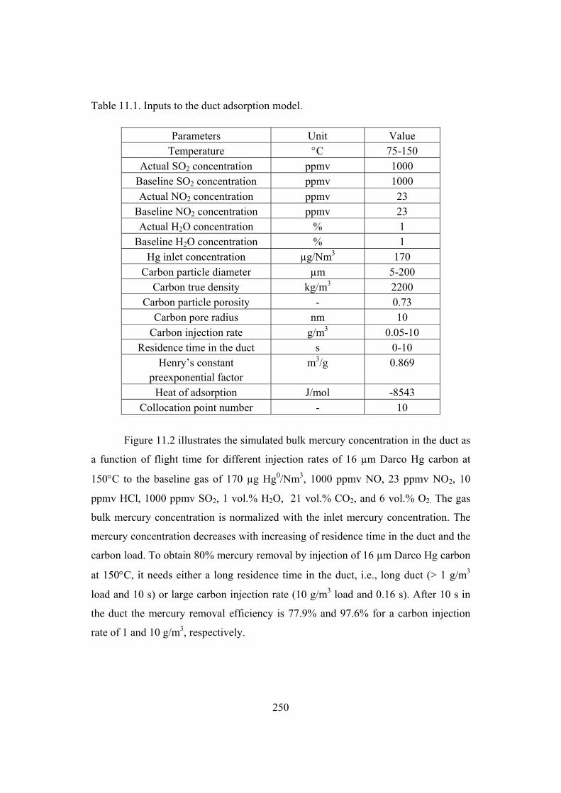
250
Table 11.1. Inputs to the duct adsorption model.
Parameters Unit Value Temperature C 75-150
Actual SO2 concentration ppmv 1000 Baseline SO2 concentration ppmv 1000 Actual NO2 concentration ppmv 23
Baseline NO2 concentration ppmv 23 Actual H2O concentration % 1
Baseline H2O concentration % 1 Hg inlet concentration µg/Nm3 170
Carbon particle diameter µm 5-200 Carbon true density kg/m3 2200
Carbon particle porosity - 0.73 Carbon pore radius nm 10
Carbon injection rate g/m3 0.05-10 Residence time in the duct s 0-10
Henry’s constant preexponential factor
m3/g 0.869
Heat of adsorption J/mol -8543 Collocation point number - 10
Figure 11.2 illustrates the simulated bulk mercury concentration in the duct as
a function of flight time for different injection rates of 16 µm Darco Hg carbon at
150C to the baseline gas of 170 µg Hg0/Nm3, 1000 ppmv NO, 23 ppmv NO2, 10
ppmv HCl, 1000 ppmv SO2, 1 vol.% H2O, 21 vol.% CO2, and 6 vol.% O2. The gas
bulk mercury concentration is normalized with the inlet mercury concentration. The
mercury concentration decreases with increasing of residence time in the duct and the
carbon load. To obtain 80% mercury removal by injection of 16 µm Darco Hg carbon
at 150C, it needs either a long residence time in the duct, i.e., long duct (> 1 g/m3
load and 10 s) or large carbon injection rate (10 g/m3 load and 0.16 s). After 10 s in
the duct the mercury removal efficiency is 77.9% and 97.6% for a carbon injection
rate of 1 and 10 g/m3, respectively.

251
Figure 11.2. Simulated gaseous mercury concentration as a function of residence time
in the duct and carbon injection rate. Darco Hg carbon with a diameter of 16 µm is
injected at 150C to simulated cement kiln flue gas with 170 µg Hg0/Nm3, 1000
ppmv NO, 23 ppmv NO2, 10 ppmv HCl, 1000 ppmv SO2, 1 vol.% H2O, 21 vol.%
CO2, and 6 vol.% O2.
The effects of carbon particle size on mercury concentration in the duct are
illustrated in figure 11.3. The gas bulk mercury concentration decreases faster for
smaller carbon particles during the first 2 s in the duct and a larger mercury removal
is obtained by smaller carbon particles at all residence time, indicating that diffusion
resistance is relevant for mercury adsorption on carbon particles. Decreasing the
particle size from 16 to 5 µm can increase the mercury removal efficiency from 77.9
to 87.6% using an injection rate of 1 g/m3 at 150C. The improvement of mercury
removal efficiency by further lowering the particle size is less pronounced (not shown
in figure 11.3).

252
Figure 11.3. Simulated gaseous mercury concentration as a function of residence time
in the duct and carbon particle size. 1 g/m3 Darco Hg carbon is injected at 150C to
simulated cement kiln flue gas with 170 µg Hg0/Nm3, 1000 ppmv NO, 23 ppmv NO2,
10 ppmv HCl, 1000 ppmv SO2, 1 vol.% H2O, 21 vol.% CO2, and 6 vol.% O2.
The effects of particle size on mercury removal can be explained by Biot
numbers for different particle sizes as shown in table 10.5. Calculations show that the
larger the particle is, the smaller external mass transfer coefficient, the larger the Biot
numbers are. This indicates that the larger particle has relatively larger internal
transfer resistance. As a result, it takes the larger particle longer time to reach the
equilibrium. In all the cases calculated here, the Biot numbers are much larger than
36, indicating that the internal diffusional resistance is much larger than the external
mass transfer resistance.
The effects of temperature on mercury removal in the duct are presented in
figure 11.4. Similar mercury outlet concentrations are observed for injection 0.5 g/m3
Darco Hg carbon with a size of 16 µm for the first 2 s in the duct, and then lower
mercury outlet concentrations are obtained with lower flue gas temperature and
longer residence time in the duct.
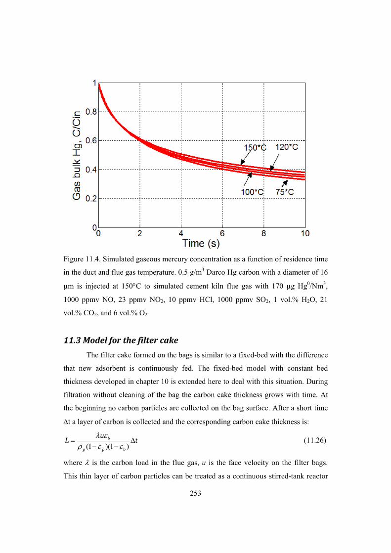
253
Figure 11.4. Simulated gaseous mercury concentration as a function of residence time
in the duct and flue gas temperature. 0.5 g/m3 Darco Hg carbon with a diameter of 16
µm is injected at 150C to simulated cement kiln flue gas with 170 µg Hg0/Nm3,
1000 ppmv NO, 23 ppmv NO2, 10 ppmv HCl, 1000 ppmv SO2, 1 vol.% H2O, 21
vol.% CO2, and 6 vol.% O2.
11.3 Model for the filter cake
The filter cake formed on the bags is similar to a fixed-bed with the difference
that new adsorbent is continuously fed. The fixed-bed model with constant bed
thickness developed in chapter 10 is extended here to deal with this situation. During
filtration without cleaning of the bag the carbon cake thickness grows with time. At
the beginning no carbon particles are collected on the bag surface. After a short time
t a layer of carbon is collected and the corresponding carbon cake thickness is:
(1 )(1 )b
p p b
uL t
(11.26)
where is the carbon load in the flue gas, u is the face velocity on the filter bags.
This thin layer of carbon particles can be treated as a continuous stirred-tank reactor

254
(CSTR). The bed volume is AL, the mass of carbon in the tank
is (1 ) (1 )(1 )b p b p p bM V AL . The mass balance for mercury in the bulk
phase in the tank becomes:
3(1 )( ) ( )
p
b b mbin b b R
b p
dC kuC C C C
dt L R
(11.27)
The dimensionless equation can be written as:
2
1
3(1 )( ) ( )pb b m
bin b bapp b p
Rdy kuy y y y
d D L R
(11.28)
n+1 collocation points are used for the carbon particle. The bulk phase mercury
balance equation becomes:
2
22 2 1
3(1 )( ) ( )pn b m
bin n n napp b p
Rdy kuy y y y
d D L R
(11.29)
Initial and boundary conditions:
=0, y=0, ybin=1 (11.30)
0, 0y
uu
(11.31)
)(2
;1 12
nn yyBi
u
yu (11.32)
Theses n+1 equations are solved in a time interval of [0 t] by MATLAB
routine ode15s. After another t, another layer of carbon with thickness of L is
formed on the bag surface and on top of the first layer and is termed as tank 2. Now
the system contains 2(n+1) initial-value ordinary differential equations which are
solved simultaneously in a time interval of [0 t] by MATLAB routine ode15s. The
initial conditions for equations in tank 1 are the calculated concentration from last t
interval. The initial conditions for tank 2 are y=0, ybin,2=1. At >0, ybin,1= yb,2. The
cycle is conducted to the desired filtration time. Here it is assumed that the carbon
particles are injected just at the filter inlet. The combination of duct injection and
filter cake model will be presented in section 11.5. In the later case the carbon
particles arriving in the filter will have already adsorbed mercury with some radial
profile, i.e., y0.

255
Simulation of mercury removal by the fixed-bed with moving boundary is
performed using the conditions from the Durkee pilot plant study [7,8]. The inputs to
the model are given in table 11.2. The flue gas temperature is taken from the field test
report [7,8] and the flue gas compositions are supplied by Paone [9]. Other gas
concentrations are the same as the baseline gas. The effects of CO2 and HCl are not
accounted for since the effects of these gases are less pronounced compared to SO2,
NO2 and H2O. Referring to results from chapter 8, when the CO2 level in the flue gas
is above 21 vol.%, which is used in baseline test and deriving of the adsorption
kinetics, the mercury adsorption capacity of the carbon is only slightly decreased.
With HCl in the gas up to 15 ppmv, the mercury adsorption capacity is almost not
affected by changing the HCl level in the gas. Large adsorption capacity is obtained
without HCl in the gas.
Table 11.2. Inputs to the filter cake model.
Parameters Unit Value Temperature C 138
Actual SO2 concentration ppmv 5 Baseline SO2 concentration ppmv 1000 Actual NO2 concentration ppmv 5
Baseline NO2 concentration ppmv 23 Actual H2O concentration % 15
Baseline H2O concentration % 1 Hg inlet concentration µg/Nm3 200
Carbon particle diameter µm 16 Carbon true density kg/m3 2200
Carbon particle porosity - 0.73 Carbon pore radius nm 10
Carbon injection rate mg/m3 8-80 Filtration time s 1500
Air to cloth ratio m/min 1.2 Time for new cake layer min 0.5-5
Henry’s constant preexponential factor
m3/g 0.869
Heat of adsorption J/mol -8543 Collocation point number - 10

256
The effect of the time for new carbon layer addition t on the mercury
removal efficiency of the fabric filter is illustrated in figure 11.5. Generally the more
frequently the new layer is added the larger mercury removal efficiency is obtained
for filtration time less than 1200 s. Smoother mercury removal efficiency curve will
be obtained using a smaller time interval for adding a carbon layer. For short
filtration time the new carbon layer should be added very fast in the simulation,
otherwise the simulated mercury removal efficiency will be smaller due to the delay
of new carbon layer addition. For filtration time larger than 1200 s same mercury
removal efficiency is predicted with 5 min interval for new carbon layer addition as
with smaller time interval. However, the computation time of the program is
considerably reduced using an interval of 5 min compared to 1 min.
0 300 600 900 1200 1500 18000
10
20
30
40
50
60
70
Time (s)
Mer
cury
rem
ova
l, %
30 s60 s120 s300s
Figure 11.5. Simulated effects of new cake layer addition frequency on the mercury
removal efficiency of a fabric filter without cleaning of the bags. 16 mg/m3 Darco Hg
carbon with a diameter of 16 µm is injected at 138C to simulated cement kiln flue
gas with 200 µg Hg0/Nm3, 1000 ppmv NO, 5 ppmv NO2, 10 ppmv HCl, 5 ppmv SO2,
15 vol.% H2O, 21 vol.% CO2, and 6 vol.% O2.

257
Figure 11.6 presents the simulated mercury removal efficiency by a fabric
filter without cleaning of the bags as a function of filtration time and injection rate of
carbon. Every minute a layer of carbon is added to the bag surface. As expected,
larger mercury removal efficiency is obtained with higher carbon injection rate. The
mercury removal efficiency increases fast with time after initiating carbon injection
up to 600 s and then it slowly increases with filtration time.
Figure 11.6. Simulated mercury removal efficiency by a fabric filter without cleaning
of the bags as a function of filtration time and injection rate of carbon. Darco Hg
carbon with a diameter of 16 µm is injected at 138C to simulated cement kiln flue
gas with 200 µg Hg0/Nm3, 1000 ppmv NO, 5 ppmv NO2, 10 ppmv HCl, 5 ppmv SO2,
15 vol.% H2O, 21 vol.% CO2, and 6 vol.% O2. t= 1 min.
11.4 Fabric filter model
In reality the filter bags are periodically cleaned. Therefore the filter cake
model needs to be extended with periodical cleaning of the bags in order to simulate
mercury adsorption in the bag filter. Assuming the cleaning cycle interval is tclean,
fraction of filter cleaned per cycle is fclean. After first tclean, the carbon cakes on the

258
bag surface have different exposure time to mercury and the mercury removal
efficiency is the average of the mercury removal efficiency in different sections of the
filter. Table 11.3 illustrates the carbon cake life time in different sections of the fabric
filter and the calculation of average mercury removal efficiency across the filter as a
function of filtration time. Pulse duration is selected as 0.1 second. Symbol * means a
pulse with 0.1/60 min and indicates that a fraction of the filter bags is cleaned.
Table 11.3 Illustration of carbon cake lifetime for different filter sections due to
periodic cleaning of bags. Here tclean=25 min; fclean=0.1.
Filtration time (min)
Exposure time of different filter sections
Average mercury removal efficiency
0 0 0 0-25 10@[0 25]
[0 25]
25 10@[25] [25]
25* 1@[0], 9@[25] [ 25 ]
9
10
25*-50 1@[0 25], 9@[0 50] [ 0 25 ] [ 0 50 ]
19
1 0
50 1@[25], 9@[50] [ 25 ] [50 ]
19
10
50* 1@[0], 1@[25], 8@[50] [ 2 5 ] [ 5 0 ]
18
1 0
50*-75 1@[0-25], 1@[0 50], 8@[0 75]
[ 0 2 5 ] [ 0 5 0 ] [ 0 7 5 ]
18
1 0
75 1@[25], 1@[50], 8@[75] [ 25 ] [50 ] [ 75 ]
18
10
75* 1@[0], 1@[25], 1@[50], 7@[75]
[ 2 5 ] [ 5 0 ] [ 7 5 ]
17
10
75*-100 1@[0 25], 1@[0 50], 1@[ 0 75], 7@[0 100] [ 0 25 ] [ 0 50 ] [ 0 75 ] [ 0 100 ]
17
10
100 1@[25], 1@[50], 1@[75], 7@[100] [ 25 ] [ 50 ] [ 75 ] [100 ]
17
10
100* 1@[0], 1@[25], 1@[50], 1@[75], 6@[100] [ 25 ] [50 ] [ 75 ] [100 ]
16
10
100*-125 1@[0 25], 1@[0 50], 1@[0 75], 1@[0 100],
6@[0 125]
[0 25] [0 50 ] [0 75] [0 100 ]
[0 125]
1
610
125 1@[25], 1@[50], 1@[75], 1@[100],
6@[125]
[25] [50] [75] [100]
[125]
1
610
125* 1@[0], 1@[25], 1@[50], 1@[75], 1@[100],
5@[125]
[25] [50] [75] [100]
[125]
1
510

259
Filtration time (min)
Exposure time of different filter sections
Average mercury removal efficiency
125*-150 1@[0 25], 1@[0 50], 1@[0 75], 1@[0 100], 1@[0 125], 5@[0 150]
[0 25] [0 50] [0 75] [0 100]
[0 125] [0 150]
1
510
150 1@[25], 1@[50], 1@[75], 1@[100], 1@[125], 5@[150]
[25] [50] [75] [100]
[125] [150]
1
510
150* 1@[0], 1@[25], 1@[50], 1@[75], 1@[100], 1@[125], 4@[150]
[25] [50] [75] [100]
[125] [150]
1
410
150*-175 1@[0 25], 1@[0 50], 1@[0 75], 1@[0 100], 1@[0 125], 1@[0 150],
4@[0 175]
[0 25] [0 50] [0 75] [0 100]
[0 125] [0 150] [0 175]
1
410
175 1@[25], 1@[50], 1@[75], 1@[100], 1@[125], 1@[150],
4@[175]
[25] [50] [75] [100]
[125] [150] [175]
1
410
175* 1@[0],1@[25], 1@[50], 1@[75], 1@[100], 1@[125], 1@[150],
3@[175]
[25] [50] [75] [100]
[125] [150] [175]
1
310
175*-200 1@[0 25], 1@[0 50], 1@[0 75], 1@[0 100], 1@[0 125], 1@[0 150], 1@[0 175],3@[0 200]
[0 25] [0 50] [0 75] [0 100]
[0 125] [0 150] [0 175] [0 200]
1
310
200 1@[25], 1@[50], 1@[75], 1@[100], 1@[125], 1@[150], 1@[175], 3@[200]
[25] [50] [75] [100]
[125] [150] [175] [200]
1
310
200* 1@[0], 1@[25], 1@[50], 1@[75], 1@[100], 1@[125], 1@[150], 1@[175], 2@[200]
[25] [50] [75] [100]
[125] [150] [175] [200]
1
210
200*-225 1@[0 25], 1@[0 50], 1@[0 75], 1@[0 100], 1@[0 125], 1@[0 150], 1@[0 175], 1@[0 200],
2@[0 225]
[0 25] [0 50] [0 75] [0 100]
[0 125] [0 150] [0 175] [0 200]
[0 225]
1
102
225 1@[25], 1@[50], 1@[75], 1@[100], 1@[125], 1@[150], 1@[175], 1@[200],
2@[225]
[25] [50] [75] [100]
[125] [150] [175] [200]
[225]
1
102
225* 1@[0], 1@[25], 1@[50], 1@[75], 1@[100], 1@[125], 1@[150], 1@[175], 1@[200],
1@[225]
[25] [50] [75] [100]
[125] [150] [175] [200]
[225]
1
10

260
225*-250 1@[0 25], 1@[0 50], 1@[0 75], 1@[0 100], 1@[0 125], 1@[0 150], 1@[0 175], 1@[0 200], 1@[0 225], 1@[0 250]
[0 25] [0 50] [0 75] [0 100]
[0 125] [0 150] [0 175] [0 200]
[0 225] [0 250]
1
10
250 1@[25], 1@[50], 1@[75], 1@[100], 1@[125], 1@[150], 1@[175], 1@[200], 1@[225], 1@[250]
[25] [50] [75] [100]
[125] [150] [175] [200]
[225] [250]
1
10
250* 1@[0], 1@[25], 1@[50], 1@[75], 1@[100], 1@[125], 1@[150], 1@[175], 1@[200],
1@[225]
[25] [50] [75] [100]
[125] [150] [175] [200]
[225]
1
10
250*-275 1@[0 25], 1@[0 50], 1@[0 75], 1@[0 100], 1@[0 125], 1@[0 150], 1@[0 175], 1@[0 200], 1@[0 225], 1@[0 250]
[0 25] [0 50] [0 75] [0 100]
[0 125] [0 150] [0 175] [0 200]
[0 225] [0 250]
1
10
275 1@[25], 1@[50], 1@[75], 1@[100], 1@[125], 1@[150], 1@[175], 1@[200], 1@[225], 1@[250]
[25] [50] [75] [100]
[125] [150] [175] [200]
[225] [250]
1
10
275* 1@[0], 1@[25], 1@[50], 1@[75], 1@[100], 1@[125], 1@[150], 1@[175], 1@[200],
1@[225]
[25] [50] [75] [100]
[125] [150] [175] [200]
[225]
1
10
… … …
The filter cake model is run for time interval of [0 250] min. The calculated
mercury removal efficiencies at different time are used to calculate the corresponding
average mercury removal efficiency across the whole fabric filter.
The input parameters from Durkee slipstream tests listed in table 11.2 are
again used as model inputs to the fabric filter model. Other inputs include a bag
cleaning interval of 25 min and a cleaning fraction of 0.1. It is assumed that a new
sorbent layer is accumulated on the filter bag every 5 min.
Figure 11.7 shows the simulated mercury removal efficiency if the filter was
running without periodical cleaning up to 4 h. Compared to the short filtration time of
25 min as shown in figure 11.5, the mercury removal efficiency reaches a stable value
after about 1 h for the applied injection rates of powdered activated carbon. This

261
behavior is due to the growing thickness of the carbon cake. Fresh carbon is
continuously injected to the filter, providing increased mercury adsorption. At long
times, the inner layers of the carbon cake, consisting of almost fully spent carbon,
gives negligible contribution to the process so that asymptotic conditions are reached.
Figure 11.7. Simulated mercury removal efficiency by 1/10 of the fabric filter without
cleaning of the bags as a function of filtration time and injection rate of carbon. Darco
Hg carbon with a diameter of 16 µm is injected at 138C to simulated cement kiln
flue gas with 200 µg Hg0/Nm3, 1000 ppmv NO, 5 ppmv NO2, 10 ppmv HCl, 5 ppmv
SO2, 15 vol.% H2O, 21 vol.% CO2, and 6 vol.% O2. t=5 min, Air to cloth ratio
ufilter= 1.2 m/min.
Figure 11.8 presents the simulated mercury removal efficiency across the
fabric filter with periodical cleaning 10% of the bags every 25 min. When 10% of the
bags is cleaned the mercury removal efficiency decreases. At the beginning the
mercury removal efficiency decreases slightly and it decreases more at later stage.
This is due to the fact that more carbon is collected on the filter bag and is removed
by pulse cleaning. The model assumes that all the carbon collected on the bag is
completely removed from the bag surface and the corresponding mercury removal
efficiency for this fraction of bags drops to zero when the pulse cleaning is initiated.
The mercury removal efficiency across the whole filter reaches a stable level after all
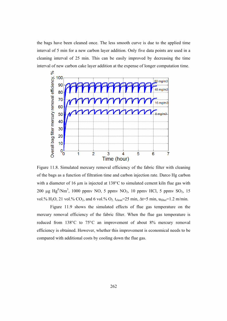
262
the bags have been cleaned once. The less smooth curve is due to the applied time
interval of 5 min for a new carbon layer addition. Only five data points are used in a
cleaning interval of 25 min. This can be easily improved by decreasing the time
interval of new carbon cake layer addition at the expense of longer computation time.
Figure 11.8. Simulated mercury removal efficiency of the fabric filter with cleaning
of the bags as a function of filtration time and carbon injection rate. Darco Hg carbon
with a diameter of 16 µm is injected at 138C to simulated cement kiln flue gas with
200 µg Hg0/Nm3, 1000 ppmv NO, 5 ppmv NO2, 10 ppmv HCl, 5 ppmv SO2, 15
vol.% H2O, 21 vol.% CO2, and 6 vol.% O2. tclean=25 min, t=5 min, ufilter=1.2 m/min.
Figure 11.9 shows the simulated effects of flue gas temperature on the
mercury removal efficiency of the fabric filter. When the flue gas temperature is
reduced from 138C to 75C an improvement of about 8% mercury removal
efficiency is obtained. However, whether this improvement is economical needs to be
compared with additional costs by cooling down the flue gas.

263
0 1 2 3 4 5 6 70
10
20
30
40
50
60
70
80
Time (hour)
Ove
rall
bag
filte
r m
ercu
ry r
emov
al e
ffici
ency
, %1234
1: 75 degree C2: 100 degree C3: 115 degree C4: 138 degree C
Figure 11.9. Simulated effects of flue gas temperature on mercury removal efficiency
of the fabric filter. 16 mg/m3 Darco Hg carbon with a diameter of 16 µm is injected to
simulated cement kiln flue gas with 200 µg Hg0/Nm3, 1000 ppmv NO, 5 ppmv NO2,
10 ppmv HCl, 5 ppmv SO2, 15 vol.% H2O, 21 vol.% CO2, and 6 vol.% O2. tclean=25
min, t=5 min, ufilter= 1.2 m/min.
11.5 Twostage model
Models developed in previous sections simulate mercury removal by separate
parts of the full-scale process. In this section mercury adsorption in the duct section is
coupled with the fabric filter section. First the duct model is run. The mercury
concentrations inside the particle and the bulk mercury concentration at the end of the
duct are used as initial conditions for the fabric filter model. Then the fabric filter
model is run to desired filtration time. The model inputs are the same as the fabric
filter model. A flight time of 1 s in the duct is applied.
Figure 11.10 shows the simulated mercury removal efficiency in the duct
section at Durkee cement plant. When a smaller carbon injection rate is applied the
mercury removal efficiency after 1 s in the duct is negligible. As shown in figure

264
11.10, about 2% mercury removal is obtained when 16 mg/m3 Darco Hg carbon is
injected. However, at larger carbon injection rates the mercury removal efficiency
after 1 s in the duct is noticeable. Therefore, high mercury removal efficiency can be
obtained by increasing the residence time of carbon particles in the duct, i.e., by
applying long duct, provided that there is enough space in the plant and large carbon
injection rate is applied.
Figure 11.10. Simulated mercury removal efficiency in the duct as a function of
residence time and injection rate of carbon. Darco Hg carbon with a diameter of 16
µm is injected at 138C to simulated cement kiln flue gas with 200 µg Hg0/Nm3,
1000 ppmv NO, 5 ppmv NO2, 10 ppmv HCl, 5 ppmv SO2, 15 vol.% H2O, 21 vol.%
CO2, and 6 vol.% O2.
Figure 11.11 compares the simulated and measured mercury removal
efficiency of the fabric filter at Durkee slipstream plant. Generally there is good
agreement between the simulation and pilot-scale data. This indicates that the
adsorption kinetics derived from 10 mg Darco Hg carbon in 2 g sand is reasonable
and the developed model is a useful tool to simulate and optimize the carbon injection
process.

265
0 10 20 30 40 50 60 70 80 90 100
Activated carbon injection rate (mg/m3)
0
10
20
30
40
50
60
70
80
90
100
Mer
cury
rem
ova
l ove
r th
e fi
lter
(%
)
ModelData
Figure 11.11. Comparison of simulated and measured mercury removal efficiency of
the fabric filter at Durkee slipstream plant. Darco Hg carbon with a diameter of 16
µm is injected at 138C to simulated cement kiln flue gas with 200 µg Hg0/Nm3,
1000 ppmv NO, 5 ppmv NO2, 10 ppmv HCl, 5 ppmv SO2, 15 vol.% H2O, 21 vol.%
CO2, and 6 vol.% O2. tclean=25 min, t=5 min, ufilter= 1.2 m/min.
The overall mercury removal efficiency of the sorbent injection system refers
to mercury removal from the carbon injection point to the fabric filter outlet and can
be evaluated as following:
100 (1 (1 %)(1 %))total duct filter (11.33)
Table 11.4 summarizes the calculated mercury removal efficiencies in the duct, fabric
filter and the whole carbon injection system for different carbon injection rates. The
contribution of mercury removal in the duct is much smaller to the mercury removal
in the whole carbon injection system. However, data regarding overall mercury
removal for the Durkee slipstream plant are not available for comparison.

266
Table 11.4 Simulated mercury removal efficiencies in the duct, fabric filter and the
whole carbon injection system for different carbon injection rates. Darco Hg carbon
with a diameter of 16 µm is injected at 138C to simulated cement kiln flue gas with
200 µg Hg0/Nm3, 1000 ppmv NO, 5 ppmv NO2, 10 ppmv HCl, 5 ppmv SO2, 15
vol.% H2O, 21 vol.% CO2, and 6 vol.% O2. Carbon particle residence time in the
duct is 1 s. Every five minute a layer of carbon is added to the bag surface. Air to
cloth ration is 1.2 m/min.
Carbon load (mg/m3)
Mercury removal in duct (%)
Mercury removal in fabric filter (%)
Total Mercury removal (%)
8 1.0 54.0 54.5 16 2.0 69.6 70.2 48 5.9 86.0 86.9 80 9.7 90.3 91.2
The applied carbon injection rate for mercury control is much smaller than the
typical dust load in the flue gas for particulate emission control process. Therefore,
the pressure drop over the fabric filter is expected to increase slowly with filtration
time for mercury control process. It is then feasible to extend the bag cleaning
interval, i.e., use less frequent cleaning of the bags. Figure 11.12 illustrates the
simulated effects of bag cleaning frequency on the mercury removal efficiency of the
fabric filter. The mercury removal efficiency slightly increases when the bag cleaning
interval is increased. Extending the bag cleaning interval from 25 min to 100 min
results in a 1.3% improvement of mercury removal efficiency. A longer bag cleaning
cycle results in longer retention time of the carbon particles on the bags, which allows
the carbon particles to adsorb more mercury from the flue gas.

267
25 50 75 100 125
Bag cleaning interval (min)
86
86.4
86.8
87.2
87.6
88
Hg
rem
ova
l eff
icie
nc
y, %
Figure 11.12. Simulated effects of bag cleaning frequency on mercury removal
efficiency of the fabric filter. 48 mg/m3 Darco Hg carbon with a diameter of 16 µm is
injected at 138C to simulated cement kiln flue gas with 200 µg Hg0/Nm3, 1000
ppmv NO, 5 ppmv NO2, 10 ppmv HCl, 5 ppmv SO2, 15 vol.% H2O, 21 vol.% CO2,
and 6 vol.% O2. tclean=25 min, t=5 min, ufilter= 1.2 m/min.
The only carbon injection system for mercury control from cement production
is operated at Ash Grove’s Durkee cement plant [10]. Instead of continuous injection
of powdered activated carbon, the fabric filter works in fixed-bed adsorber mode.
During the first run period, the activated carbon was added to the system through the
first day and removed from the system through the eighth day. The average removal
efficiency during those intervening 6 days was 92.8% [10]. However, the carbon
injection rate and duration in the first day is not reported.
Simulations are performed to simulate the fabric filter fixed-bed operation
mode. Firstly activated carbon is injected at high load for 30 min to form a carbon
cake on the bags. Then the activated carbon injection is stopped and the fabric filter
works as a fixed-bed adsorber. When the initial mercury breakthrough occurs or the
mercury emission limit is reached, the bags are cleaned by pulse-jet compressed air
and later activated carbon is injected again. The injection-adsorption-cleaning cycle is
repeated. The carbon injection without bag cleaning period is simulated by the filter
cake model and the fixed-bed adsorption period is simulated by the fixed-bed model.

268
Figure 11.13 shows the simulated mercury breakthrough curves of the fabric
filter injected with 0.5-2.0 g/m3 Darco Hg carbon for 30 min. The actual carbon
injection rate at full-scale test is not available and high carbon injection rates are
tested here to show the effect. The initial mercury breakthrough time for carbon load
of 0.5, 1.0, 1.5, and 2.0 g/m3 is 17.9, 35.7, 53.6, and 71.5 h, respectively. This means
that about 100% mercury removal efficiency is obtained within the initial mercury
breakthrough periods. With an activated carbon injection of 1-2 g/m3 for 30 min, the
fabric filter can work for 53.6 to 71.5 h before the initial breakthrough occurs. This
means that the activated carbon injection is only required 2-3 times per week. This is
in agreement with the information obtained from Paone [9] on practice of the Durkee
sorbent injection plant. However, the actual carbon injection rate and duration at
Durkee plant are unknown and are required for validation of the simulation.
0 50 100 150 200 250 300 350 4000
0.2
0.4
0.6
0.8
1
1.2
Time (hour)
Gas
eous
mer
cury
out
let
(Cou
t/C
in)
A
A: 0.5 g/m3B: 1.0 g/m3C: 1.5 g/m3D: 2.0 g/m3
CB D
Figure 11.13. Simulated mercury breakthrough curves of fabric filter injected with
large carbon loads for 30 min and then in fixed-bed operation mode. Darco Hg
carbon with a diameter of 16 µm is injected at 138C to simulated cement kiln flue
gas with 200 µg Hg0/Nm3, 1000 ppmv NO, 5 ppmv NO2, 10 ppmv HCl, 5 ppmv SO2,
15 vol.% H2O, 21 vol.% CO2, and 6 vol.% O2.

269
To compare with mercury removal by continuous injection of carbon,
simulations are conducted by injection of the same total amount of carbon within the
initial mercury breakthrough period. The corresponding carbon injection rate is 14
mg/m3 and the simulated mercury removal efficiency is only 66.8%. The fabric filter
works more efficiently for mercury removal in fixed-bed operation model than
continuous injection of carbon for the same total amount of carbon injected. This is
probably due to the larger amount of carbon accumulated on the bags in the fixed-bed
operation mode. The fixed-bed operation model is limited by the pressure drop over
the fabric filter. It is expected that a larger pressure drop over the filter and power
consumption of the system is required when a large carbon injection rate is applied in
a reasonable period.
11.6 Conclusions
The developed single particle and fixed-bed adsorption models are further
extended to duct and fabric filter models to simulate mercury removal by carbon
injection upstream of a fabric filter. The fabric filter model is accounted for by adding
a new carbon layer on the bag surface after a short time and treating each layer as a
well mixed tank. Finally the duct model and fabric filter model are coupled to a two-
stage model. The mercury concentrations inside the particle and the bulk mercury
concentration at the end of the duct are used as initial conditions for the fabric filter
model. The models are based on materials balances in both gaseous and adsorbed
phase along the duct length/growing filter cake and inside the carbon particles. The
models account for adsorption kinetics, both the external and internal mass transfer
resistances, accumulation of carbon layer on the bags, and periodical cleaning of the
bags.
Henry’s constant obtained from fixed-bed investigation of mercury adsorption
by activated carbon in the simulated cement kiln flue gas is used as input to the
models. The effects of SO2, H2O, NO2 levels in the flue gas on mercury removal are
accounted by using correlations derived from the fixed-bed investigation.
Duct model simulations indicate that large carbon loading in the flue gas are
required to obtain high mercury removal efficiency due to the short residence time.

270
To minimize the carbon feed rate it is advisable to lower the operating temperature.
Improvements in the mercury removal efficiency can be obtained also by increasing
the in-duct particle residence time and decreasing the carbon particle size.
In contrast to the in-duct removal process, simulations of mercury adsorption
in the fabric filter show that higher mercury removal efficiency can be achieved with
moderate carbon consumption due to the effective gas/carbon contact on the filter
bags. The effects of carbon load, temperature, frequency of new carbon layer addition
and bag cleaning on mercury removal efficiency are simulated. The fabric filter
model can predict the mercury removal profile with jagged nature because of the
intermittent partial cleaning of the bags. Comparison with simulation and
experimental data from Durkee cement plant slipstream tests shows that the
developed two-stage model can reasonably predict the mercury removal from cement
plants by carbon injection upstream of a fabric filter.
Minor benefits can be obtained by increasing the cleaning cycle time of the
fabric filter compartments. The fabric filter works more efficiently on mercury
removal when it is operated as fixed-bed adsorbed by injection of high carbon load in
short time and then stopping carbon injection and cleaning of the bags.
11.7 List of symbols
A: total exterior surface area of all particles in the adsorber (m2) A: matrix in equation 11.18 B: matrix in equation 11.19 Bi: dimensionless Biot number C: gaseous mercury concentration (µg/m3) C: matrix in equation 11.20 and 11.21 Cb: gas bulk mercury concentration (µg/m3) Cbo: initial gas bulk mercury concentration (µg/m3) Cbin: inlet mercury concentration in tank (µg/m3) Cµ: adsorbed mercury concentration in the sorbent (µg/m3) Dapp: apparent diffusion coefficient (m2/s) De: effective diffusion coefficient (m2/s) fclean: fraction of bags cleaned per pulse cleaning J: mercury flux (µg/m2) K: Henry’s constant

271
km: gas film mass transfer coefficient (m/s) L: thickness of carbon cake (m) mp: mass of carbon particle in the adsorber (g) M: carbon load in the tank (mg) n: number of interior collocation points r: radial coordinate (m) Rp: carbon particle radius (m) t: time (s) tclean: time interval for bag cleaning (25) u: dimensionless parameter, u=x2 u: face velocity on the filter bags (m/s) ufilter: air to cloth ratio (m/min) V: volume of the adsorber (m3) Vb: volume of the adsorber (m3) x: dimensionless radius y: dimensionless mercury concentration yb: dimensionless gas bulk mercury concentration (µg/m3) ybin: dimensionless inlet mercury concentration in tank (µg/m3) Greek symbols b: bed void fraction p: carbon particle porosity p: carbon particle density (kg/m3) : dimensionless time : carbon load in the flue gas (kg/m3) : mercury removal efficiency (%)
11.8 References
[1] J.R.V. Flora, R.A. Hargis, W.J. O'Dowd, A. Karash, H.W. Pennline, R.D. Vidic, The role
of pressure drop and flow redistribution on modeling mercury control using sorbent injection
in baghouse filters, J. Air Waste Manage. Assoc. 56 (2006) 343-349.
[2] F. Scala, Simulation of mercury capture by activated carbon injection in incinerator flue
gas. 1. In-duct removal, Environ. Sci. Technol. 35 (2001) 4367-4372.
[3] F. Scala, Simulation of mercury capture by activated carbon injection in incinerator flue
gas. 2. Fabric filter removal, Environ. Sci. Technol. 35 (2001) 4373-4378.
[4] F. Scala, Modeling mercury capture in coal-fired power plant flue gas, Ind Eng Chem Res.
43 (2004) 2575-2589.
[5] J. Villadsen, M.L. Michelsen, Solutions of differential equation models by polynomial
approximation, Prentice-Hall, Inc., 1978.

272
[6] D.D. Do, Adsorption analysis: equilibria and kinetics, Imperial College Press, 1998.
[7] L. Hayes-Gorman, Regulating mercury emissions: Ash Grove Cement in Durkee, Air
toxics summit 2008, Boise, Idaho, 4-7 August, 2008.
[8] Schreiber & Yonley Associates, Mercury emissions test report, Ash Grove Cement
Company Durkee, Oregon, Project No. 060204, 2007.
[9] P. Paone, Personal communication about flue gas compositions and temperature for pilot-
scale sorbent injection tests at Ash Grove Durkee plant and FLSmidth Mineral Lab, 2010.
[10] Curtis D. Lesslie, Mail to U.S.EPA about initial results of Ash Grove's Durkee sorbent
injection system, http://www.whitehouse.gov/sites/default/files/omb/assets/ oira_2060/2060_
07292010-3.pdf, visited March 21, 2011.

273
12
Concluding remarks
To develop and get a better understanding of mercury removal from cement
plant by sorbent injection upstream of a pulse jet fabric filter, this project has focused
on four areas: comprehensive review of mercury emission from cement plants and
analysis applicability of available technologies for mercury removal from cement
plants, test and development of thermal catalytic converters for oxidized mercury
reduction and dynamic total mercury measurement, screening tests and fundamental
investigation of mercury adsorption by sorbents in simulated cement kiln flue gas,
and development of mathematic models that can describe mercury removal by fixed-
bed and carbon injection upstream of a fabric filter.
Cement plants are quite different from power plants and waste incinerators
regarding the flue gas composition, temperature, residence time, and inherent
material circulation. Instead of fuel, cement raw materials are the dominant sources of
mercury in the cement kiln flue gas. The mercury emissions and speciation from
cement kilns can vary over time and depend on raw materials and fuels used, and
process operation. Among the available technologies for mercury removal from flue
gas, sorbent injection upstream of a polishing fabric filter is considered as the most
promising and suitable technology for cement plant application.
To be able to perform dynamic measurement of mercury adsorption by
sorbents, a red brass chips and sulfite converter were investigated in simulated
cement kiln flue gas. The red brass converter works only when measuring elemental
mercury in nitrogen and does not work properly even when only elemental mercury is
added to the simulated flue gas. The red brass converter cannot fully reduce HgCl2 to
elemental mercury under any relevant condition.
The sodium sulfite converter material was prepared by dry impregnation of
sodium sulfite and calcium sulfate powders on zeolite pellets using water glass as
274
binder. The sulfite converter works well at 500C when less than 10 ppmv HCl is
present in the simulated cement kiln flue gas. The response time of the sulfite
converter is short and typically within at most two minutes, which makes it
appropriate for not too fast dynamic measurements.
Inconsistent mercury adsorption capacity of activated carbon is observed at
different carbon loads in 2 g sand. A smaller mercury adsorption capacity is obtained
with larger carbon load. Tests with elemental mercury and mercury chloride, different
carbon type and particle sizes show the same trend. Effects of bed dilution on the
equilibrium mercury adsorption capacity appear to be limited.
Screening tests of sorbents for mercury removal from cement plants have
been conducted in the fixed-bed reactor system using simulated cement kiln flue gas
with elemental mercury and mercury chloride source. The tested sorbents include
commercial activated carbons, commercial non-carbon sorbents, and cement
materials. Screening measurements are used to evaluate initial mercury capture rate,
oxidation potential, and capacity for the selected sorbents.
The sorbents don’t adsorb any mercury when tested with elemental mercury
in nitrogen. Tests of a range of 30 mg collected non-carbon based sorbents and
cement materials as sorbents in 2 g sand at 150C in simulated cement kiln flue gas
with elemental mercury do not show any mercury adsorption or oxidation. Generally
a larger amount of adsorbed mercury is obtained with sorbents that have larger
mercury oxidation capacity. While all the non-carbon based sorbents and cement
materials show some adsorption of mercury chloride. This indicates that mercury
oxidation is an important factor for mercury adsorption by the sorbents. Elemental
mercury needs to be oxidized either in the flue gas with HCl or on the sorbent.
Among the tested sorbents the Darco Hg activated shows the best performance of
adsorption of both elemental and oxidized mercury and is recommended as the
reference sorbent for fundamental investigation.
A parametric study of elemental mercury adsorption by activated carbon has
been conducted in the fixed-bed reactor by mixing 10 mg Darco Hg carbon with 2 g
sand. Increasing adsorption temperature results in decreased equilibrium mercury
adsorption capacity of the activated carbon. The mercury adsorption isotherm follows
275
Henry’s law for the applied mercury inlet levels in this project. The derived heat of
adsorption is -8540 J/mol for elemental mercury adsorption by Darco Hg activated
carbon in simulated cement kiln flue gas. Higher mercury oxidation and initial
adsorption rate are also observed for smaller carbon particles, while the equilibrium
mercury adsorption capacity is the same.
The mercury adsorption capacity does not change with O2, CO, and NO levels
in the flue gas, but decreases when CO2, H2O, SO2, and NO2 concentrations increase.
The decrease of mercury adsorption capacity is due to the competition for active site
with mercury by CO2 and H2O, and conversion of the previously formed nonvolatile
basic mercuric nitrate into the volatile form by interactions between SO2 and NO2.
Slight promoting effects of HCl on mercury adsorption are observed when HCl
concentration is varied in the range of 0.5-20 ppmv. Larger mercury adsorption
capacity is obtained when HCl is removed from baseline gas because HgO(s) is
formed on the carbon.
Similar adsorption behaviors of mercury chloride and elemental mercury by
Darco Hg activated carbon are observed using simulated cement kiln flue gas. This is
due to the effective catalytic oxidation of elemental mercury by the activated carbon.
Mathematical models are developed to simulate mercury adsorption by a
single carbon particle, fixed carbon bed, in the duct and fabric filter. Orthogonal
collocation method is used to solve mercury diffusion and adsorption inside a carbon
particle. The fixed-bed model is solved by tank-in-series method. The fabric filter
model is accounted for by adding a new carbon layer on the bag surface after a short
time as a well mixed tank. The two-stage duct-fabric filter model accounts for
adsorption kinetics, both the external and internal mass transfer resistances,
accumulation of carbon layer on the bags, and periodical cleaning of the bags.
Henry’s constant obtained from fixed-bed investigation are used as input to
the models. The developed fixed bed model can reasonably simulate the effects of
adsorption temperature, mercury inlet concentration, flow gas rate, carbon particle
size, and SO2, H2O, NO2 level in the flue gas on the mercury breakthrough curve of
the fixed carbon bed.

276
Duct model simulations indicate that a large carbon load is required to obtain
a high mercury removal efficiency due to the short residence time. Simulations of
mercury adsorption in the fabric filter show that higher mercury removal efficiency
can be achieved with moderate carbon consumption due to the effective gas/carbon
contact on the filter bags. The effects of carbon load, temperature, frequency of new
carbon layer addition and bag cleaning on mercury removal efficiency are simulated.
The fabric filter model can predict the mercury removal profile with jagged nature
because of the intermittent partial cleaning of the bags. Comparison with simulation
and experimental data from Durkee cement plant slipstream tests shows that the
developed two-stage model can reasonably predict the mercury removal from cement
plants by carbon injection upstream of a fabric filter.

277
13
Suggestions for further work
This work has investigated the mercury removal by carbon injection upstream
of a fabric filter under more controlled conditions using a fixed bed reactor. Pilot or
full-scale tests are desired to demonstrate the ability of the studied sorbents and
technology to control emissions of mercury from cement plant over a typical range of
operating conditions for an extended period of time and to further validate the
developed models. The condition in full-scale application is much more demanding
than in the lab-scale investigation. Further development and test of the sulfite
converter is required for dynamic measurement of mercury in large scale
investigation. A sampling probe is needed to separate the particles from the flue gas
efficiently without plugging. Adsorption of mercury by the dust and probe should be
minimized by high sampling flow rate and high heating temperature.
The problem of inconsistent mercury adsorption capacity for different carbon
loads could not be solved within the project. More thorough investigation is
necessary to reveal the cause. New analysis technology is required to reveal whether
mercury is adsorbed by the sand when it is mixed with activated carbon.
This project investigates only mercury removal by the activated carbon. In the
future multipollutants control by the activated carbon should be studied by measuring
also other harmful species such as SO2 and NOx. When more than one component is
involved in the adsorption system, adsorption equilibrium involving competition
between molecules of different types is needed for the understanding of the system as
well as for the design purposes.
To reduce the sorbent cost, regeneration of used sorbents should be
investigated. Recycling sorbent collected by the fabric filter to the injection process
also requires more investigation. Modification of cement materials by additives that

278
can oxidize mercury is attractive. However, the influence of the additives on the
cement quality needs to be investigated.
Models developed in this work assume that all the particles have a uniform
size. It is interesting to take the particle size distribution into account in the more
advanced model. The developed fabric filter model does not include pressure drop
over the filter. It is useful to incorporate the pressure development of the fabric filter
and pulse jet cleaning instead of assuming a constant bag cleaning interval. Current
models assume local equilibrium inside the carbon particle, simulation with a full
kinetics description of the adsorption process is necessary to investigate whether this
assumption is reasonable.