photogrammetry and ground-based laser scanning ... positioning and measurement technologies and...
TRANSCRIPT

TS26 Positioning and Measurement Technologies and Practices II - Laser Scanning and Photogrammetry Alberto Guarnieri, Antonio Vettore and Fabio Remondino TS26.4 Photogrammetry and Ground-based Laser Scanning: Assessment of Metric Accuracy of the 3D Model of Pozzoveggiani Church FIG Working Week 2004 Athens, Greece, May 22-27, 2004
1/15
Photogrammetry and Ground-based Laser Scanning: Assessment of Metric Accuracy of the 3D Model of Pozzoveggiani Church
Alberto GUARNIERI, Antonio VETTORE, Italy and Fabio REMONDINO,
Switzerland
Key words: Bundle Adjustment, Reconstruction, Laser Scanner, Registration SUMMARY Among the plenty of works so far presented on the use of laser scanning for cultural heritage survey, it can be noted that some geometric related issues have been not yet solved for. Most effort has been spent to achieve visually pleasant 3D models, mainly for VR applications, but only a few works addressed the metric and geometric accuracy of generated 3D models. According to such remark, in this paper we report the results from the comparison between digital photogrammetry and laser scanning techniques applied to the survey of the outside of the ancient church of Pozzoveggiani, located in the sourrounding of Padua (Italy). To this aim, the work was carried out according to three different stages. Firstly a classic topographic/photogrammetric survey was performed: digital color images were acquired with a prosumer digital camera and then post-processed using a photogrammetric bundle adjustment and a commercial software (PhotoModeler). In the second stage the church has been fully surveyed with a ground-based laser scanner, Mensi GS100 and corresponding model was generated employing Polyworks as modeling software. Then, in the third stage the metric accuracy of both the 3D models has been assessed by comparing the coordinates of common points. To this end a set of check points were measured on the walls of the church by a total station, in order to provide a common reference system. Comparisons were based on natural targets only in order to evaluate the performance of the whole 3D modeling framework, from data acquisition to model generation, when working in a worst case scenario, i.e. when no retroreflective targets can be used.
TS26 Positioning and Measurement Technologies and Practices II - Laser Scanning and Photogrammetry Alberto Guarnieri, Antonio Vettore and Fabio Remondino TS26.4 Photogrammetry and Ground-based Laser Scanning: Assessment of Metric Accuracy of the 3D Model of Pozzoveggiani Church FIG Working Week 2004 Athens, Greece, May 22-27, 2004
2/15
Photogrammetry and Ground-based Laser Scanning: Assessment of Metric Accuracy of the 3D Model of Pozzoveggiani Church
Alberto Guarnieri, Antonio Vettore, Italy and Fabio Remondino, Switzerland
1. INTRODUCTION Photogrammetry deals since many years with the 3D reconstruction of objects from one or more images. It provides for accurate sensor calibration and object modeling using analog or digital imageries, it is very portable and many commercial software is available for image processing and 3D modeling. Laser scanning technology seems to be a very promising alternative for many kind of surveying applications. Airborne and ground-based laser scanners allow to acquire very quickly a huge amount of 3D data which can be often profitably combined with color high-resolution digital images to provide a 3D representation of the environment where we live. As a major advantage of this approach, real objects can be represented more adequately than through a single picture or collection of pictures, by providing a higher level of detail together with a good metric accuracy. These models are currently used for cultural heritage, industrial, land management or also medical applications. In the cultural heritage field, 3D models represent an interesting tool for as-built documentation and interactive visualization purposes, e.g. to create virtual reality environments. In some cases (El-Hakim, 2001) 3D models obtained by laser scanning were used to fill a virtual environment with real objects, in order to get a faithful copy of a real environment, such as the interior of a museum or historical building. Nowaday, the use of laser scanner based 3D models in VR systems (i.e. a cave) opens new perspectives both for entertainment applications and for scientific research, though a different information content is required. Indeed, while in the former case the interest is pointed mainly towards to the visual appealing (viewing quality) of the model, for scientific applications the geometric accuracy of the 3D plays the main role, regardless the size and shape complexity of surveyed object. Among the plenty of works so far presented on the use of laser scanning for cultural heritage survey, it can be noted that some geometric related issues have been not yet solved for. Most effort has been spent to achieve visually pleasant 3D models, mainly for VR applications, but only a few works addressed the metric and geometric accuracy of generated 3D models. According to such remark, in this paper we report the results from the comparison between digital photogrammetry and laser scanning techniques applied to the survey of the outside of the ancient church of Pozzoveggiani, located in the sourrounding of Padua (Italy). This little church boasts a simple geometry composed by both planar and curved surfaces, allowing to compare easily the results about the application of different surveying techniques and last but not least, a clear view of the church is available all around it, thus removing the problem of shadowing effects due to obstructions. Therefore these features made the church a good candidate for our test.

TS26 Positioning and Measurement Technologies and Practices II - Laser Scanning and Photogrammetry Alberto Guarnieri, Antonio Vettore and Fabio Remondino TS26.4 Photogrammetry and Ground-based Laser Scanning: Assessment of Metric Accuracy of the 3D Model of Pozzoveggiani Church FIG Working Week 2004 Athens, Greece, May 22-27, 2004
3/15
The presented work has been accomplished in three different stages. Firstly a classic topographic/photogrammetric survey was carried out: digital color images were acquired with a pre-calibrated prosumer digital camera, Nikon COOLPIX 5700 and then post-processed using a photogrammetric bundle adjustment and a commercial modeling software. In the second stage the church has been fully surveyed with a ground-based laser scanner, Mensi GS100 and the corresponding model was generated employing Polyworks/Modeler (Innovmetric) as modeling software. Then, in order to assess the metric accuracy, resulting 3D models were compared each other, considering the photogrammetric one as ground truth. To this end a topographic network was established with a total station, in order to provide a common reference system. Comparisons were based on natural targets only in order to evaluate the performance of the whole 3D modeling framework, from data acquisition to model generation, when working in a worst case scenario, i.e. when no retroreflective targets can be used. 2. TECHNIQUES FOR 3D OBJECT MEASUREMENT The methods to recover 3D shapes and models can be generally divided into two classes: − systems based on objects measurements; − systems that do not use measurements. 2.1 Systems Based on Measurements These techniques (Figure 1) can be mainly divided in 2 categories: − methods based on active sensor: since many years structured light (Maas, 1992; Gartner
et al, 1995; Sablatnig et al., 1997), coded light (Wahl, 1984) or laser light (Sequeira et al., 1999) are used for the measurements of objects. Nowadays many commercial solutions are available, based on triangulation, time-of-flight, continuous wave or reflectivity measurements.
− methods based on passive sensores (image-based approaches): they use 2D image measurements to recover 3D object information (e.g. photogrammetry) or they estimate surface normals instead of 3D data like shape from shading (Horn et al., 1989), shape from texture (Kender, 1978), shape from specularity (Healey et al., 1987), shape from contour (medical applications) (Meyers et al., 1992; Minoru et al., 1993; Ulupinar et al. 1995), shape from 2D edge gradients (Winkelbach et al., 2001).
Passive image-based methods acquire 3D measurements from single images or multi-stations; they use projective geometry or perspective camera model; they are very portable and the sensors are not expensive. On the other hand, 3D active sensors (mainly laser scanners) are becoming a common approach for objects or scenes recording and a standard source for geometric input data. They provide for millions of points and often also for the associated colour. But these sensors are quite expensive, designed for specific applications and depend on the reflective characteristics of the surface. A review of optical methods and active range sensors for 3D measurements is presented in (Beraldin et al., 2000; Chen et al, 2000; Blais, 2003).
TS26 Positioning and Measurement Technologies and Practices II - Laser Scanning and Photogrammetry Alberto Guarnieri, Antonio Vettore and Fabio Remondino TS26.4 Photogrammetry and Ground-based Laser Scanning: Assessment of Metric Accuracy of the 3D Model of Pozzoveggiani Church FIG Working Week 2004 Athens, Greece, May 22-27, 2004
4/15
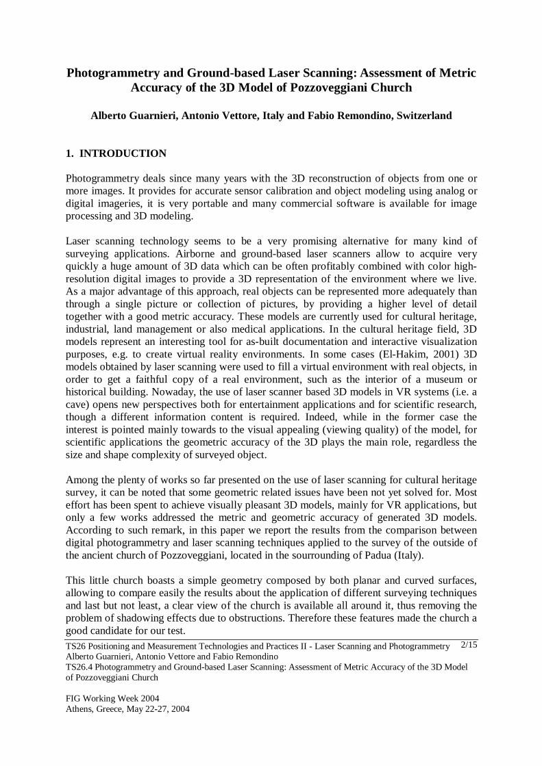
(a) (b) (c) (d) Figure 1: A photogrammetric point cloud generated with a matching algorithm between 5 images (a).
A bundle adjustment solution for multi-image photogrammetric measurement (b) (http://www.photomodeler.com). Laser scanner results with an Optech range sensor (c) (http://www.optech.com). 3D modeling of a castle with a Mensi laser scanner (d) (http://www.mensi.com).
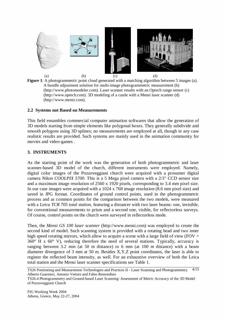
2.2 Systems not Based on Measurements This field ensambles commercial computer animation softwares that allow the generation of 3D models starting from simple elements like polygonal boxes. They generally subdivide and smooth polygons using 3D splines; no measurements are employed at all, though in any case realistic results are provided. Such systems are mainly used in the animation community for movies and video-games . 3. INSTRUMENTS As the starting point of the work was the generation of both photogrammetric and laser scanner-based 3D model of the church, different instruments were employed. Namely, digital color images of the Pozzoveggiani church were acquired with a prosumer digital camera Nikon COOLPIX 5700. This is a 5 Mega pixel camera with a 2/3" CCD sensor size and a maximum image resolution of 2560 x 1920 pixels, corresponding to 3.4 mm pixel size. In our case images were acquired with a 1024 x 768 image resolution (8.6 mm pixel size) and saved in JPG format. Coordinates of ground control points, used in the photogrammetric process and as common points for the comparison between the two models, were measured with a Leica TCR 705 total station, featuring a distancer with two laser beams: one, invisible, for conventional measurements to prism and a second one, visible, for reflectorless surveys. Of course, control points on the church were surveyed in reflectorless mode. Then, the Mensi GS 100 laser scanner (http://www.mensi.com) was employed to create the second kind of model. Such scanning system is provided with a rotating head and two inner high speed rotating mirrors, which allow to acquire a scene with a large field of view (FOV = 360° H x 60° V), reducing therefore the need of several stations. Typically, accuracy is ranging between 3.2 mm (at 50 m distance) to 6 mm (at 100 m distance) with a beam diameter divergence of 3 mm at 50 m. Besides X,Y,Z point coordinates, the laser is able to register the reflected beam intensity, as well. For an exhaustive overview of both the Leica total station and the Mensi laser scanner specifications see Table 1.
TS26 Positioning and Measurement Technologies and Practices II - Laser Scanning and Photogrammetry Alberto Guarnieri, Antonio Vettore and Fabio Remondino TS26.4 Photogrammetry and Ground-based Laser Scanning: Assessment of Metric Accuracy of the 3D Model of Pozzoveggiani Church FIG Working Week 2004 Athens, Greece, May 22-27, 2004
5/15
(a) Leica TCR 705 (b) Mensi GS100
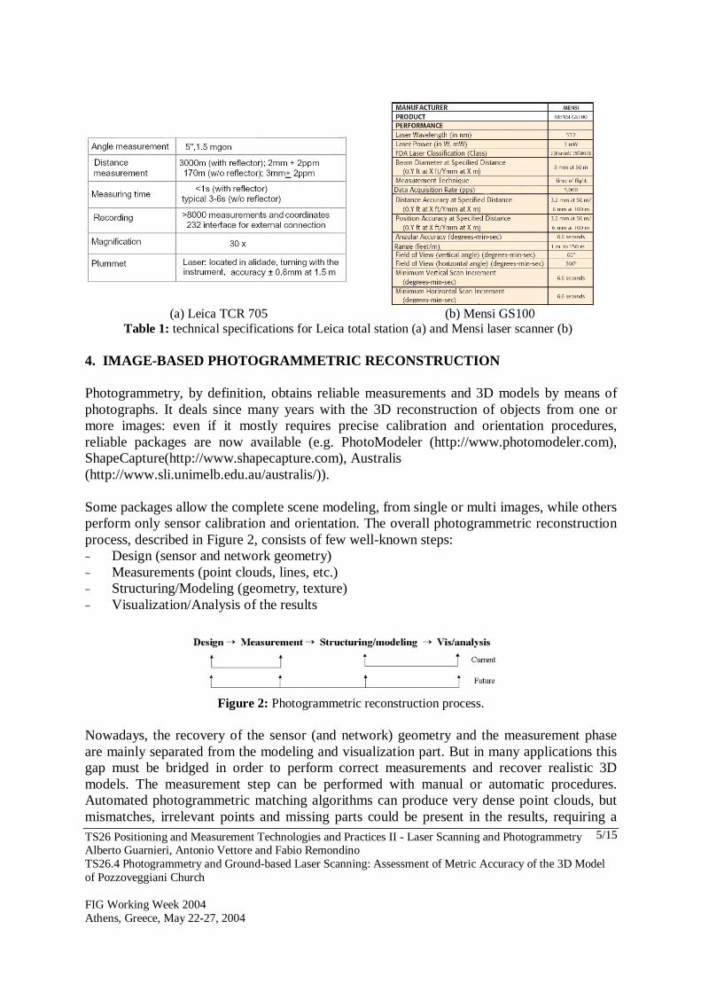
Table 1: technical specifications for Leica total station (a) and Mensi laser scanner (b) 4. IMAGE-BASED PHOTOGRAMMETRIC RECONSTRUCTION Photogrammetry, by definition, obtains reliable measurements and 3D models by means of photographs. It deals since many years with the 3D reconstruction of objects from one or more images: even if it mostly requires precise calibration and orientation procedures, reliable packages are now available (e.g. PhotoModeler (http://www.photomodeler.com), ShapeCapture(http://www.shapecapture.com), Australis (http://www.sli.unimelb.edu.au/australis/)). Some packages allow the complete scene modeling, from single or multi images, while others perform only sensor calibration and orientation. The overall photogrammetric reconstruction process, described in Figure 2, consists of few well-known steps: − Design (sensor and network geometry) − Measurements (point clouds, lines, etc.) − Structuring/Modeling (geometry, texture) − Visualization/Analysis of the results
Figure 2: Photogrammetric reconstruction process.
Nowadays, the recovery of the sensor (and network) geometry and the measurement phase are mainly separated from the modeling and visualization part. But in many applications this gap must be bridged in order to perform correct measurements and recover realistic 3D models. The measurement step can be performed with manual or automatic procedures. Automated photogrammetric matching algorithms can produce very dense point clouds, but mismatches, irrelevant points and missing parts could be present in the results, requiring a
TS26 Positioning and Measurement Technologies and Practices II - Laser Scanning and Photogrammetry Alberto Guarnieri, Antonio Vettore and Fabio Remondino TS26.4 Photogrammetry and Ground-based Laser Scanning: Assessment of Metric Accuracy of the 3D Model of Pozzoveggiani Church FIG Working Week 2004 Athens, Greece, May 22-27, 2004
6/15
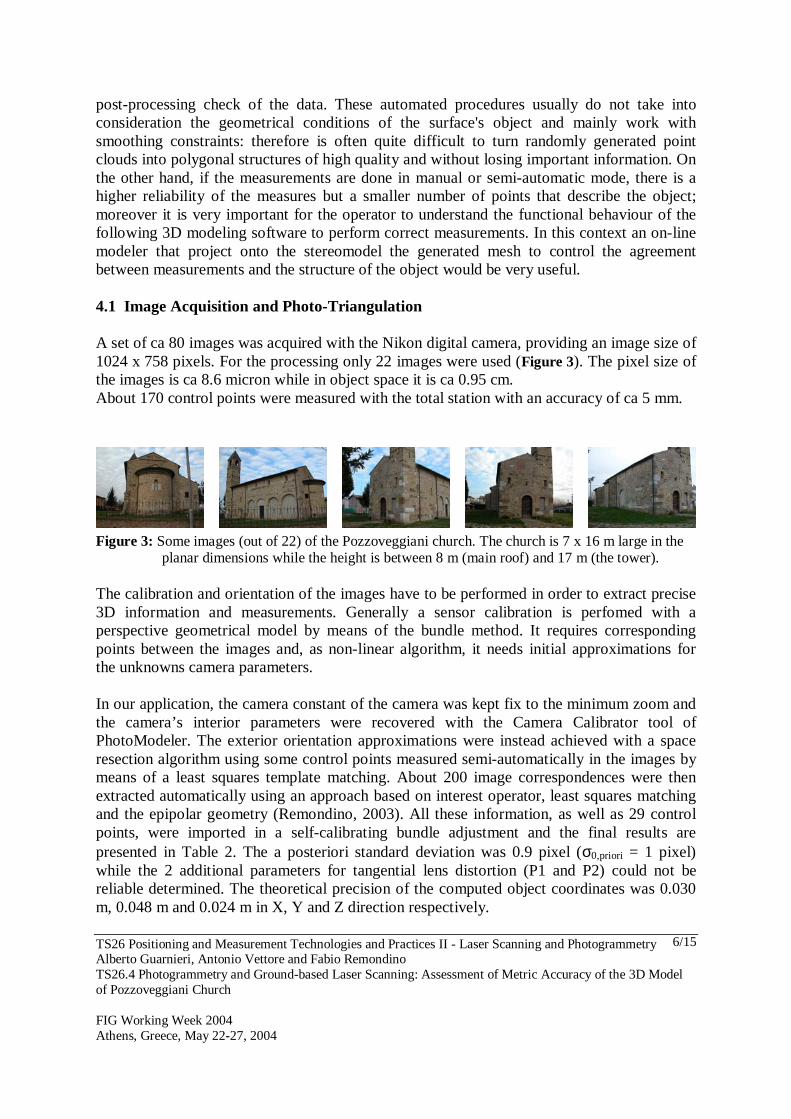
post-processing check of the data. These automated procedures usually do not take into consideration the geometrical conditions of the surface's object and mainly work with smoothing constraints: therefore is often quite difficult to turn randomly generated point clouds into polygonal structures of high quality and without losing important information. On the other hand, if the measurements are done in manual or semi-automatic mode, there is a higher reliability of the measures but a smaller number of points that describe the object; moreover it is very important for the operator to understand the functional behaviour of the following 3D modeling software to perform correct measurements. In this context an on-line modeler that project onto the stereomodel the generated mesh to control the agreement between measurements and the structure of the object would be very useful. 4.1 Image Acquisition and Photo-Triangulation A set of ca 80 images was acquired with the Nikon digital camera, providing an image size of 1024 x 758 pixels. For the processing only 22 images were used (Figure 3). The pixel size of the images is ca 8.6 micron while in object space it is ca 0.95 cm. About 170 control points were measured with the total station with an accuracy of ca 5 mm.
Figure 3: Some images (out of 22) of the Pozzoveggiani church. The church is 7 x 16 m large in the
planar dimensions while the height is between 8 m (main roof) and 17 m (the tower). The calibration and orientation of the images have to be performed in order to extract precise 3D information and measurements. Generally a sensor calibration is perfomed with a perspective geometrical model by means of the bundle method. It requires corresponding points between the images and, as non-linear algorithm, it needs initial approximations for the unknowns camera parameters. In our application, the camera constant of the camera was kept fix to the minimum zoom and the camera’s interior parameters were recovered with the Camera Calibrator tool of PhotoModeler. The exterior orientation approximations were instead achieved with a space resection algorithm using some control points measured semi-automatically in the images by means of a least squares template matching. About 200 image correspondences were then extracted automatically using an approach based on interest operator, least squares matching and the epipolar geometry (Remondino, 2003). All these information, as well as 29 control points, were imported in a self-calibrating bundle adjustment and the final results are presented in Table 2. The a posteriori standard deviation was 0.9 pixel (σ0,priori = 1 pixel) while the 2 additional parameters for tangential lens distortion (P1 and P2) could not be reliable determined. The theoretical precision of the computed object coordinates was 0.030 m, 0.048 m and 0.024 m in X, Y and Z direction respectively.
TS26 Positioning and Measurement Technologies and Practices II - Laser Scanning and Photogrammetry Alberto Guarnieri, Antonio Vettore and Fabio Remondino TS26.4 Photogrammetry and Ground-based Laser Scanning: Assessment of Metric Accuracy of the 3D Model of Pozzoveggiani Church FIG Working Week 2004 Athens, Greece, May 22-27, 2004
7/15
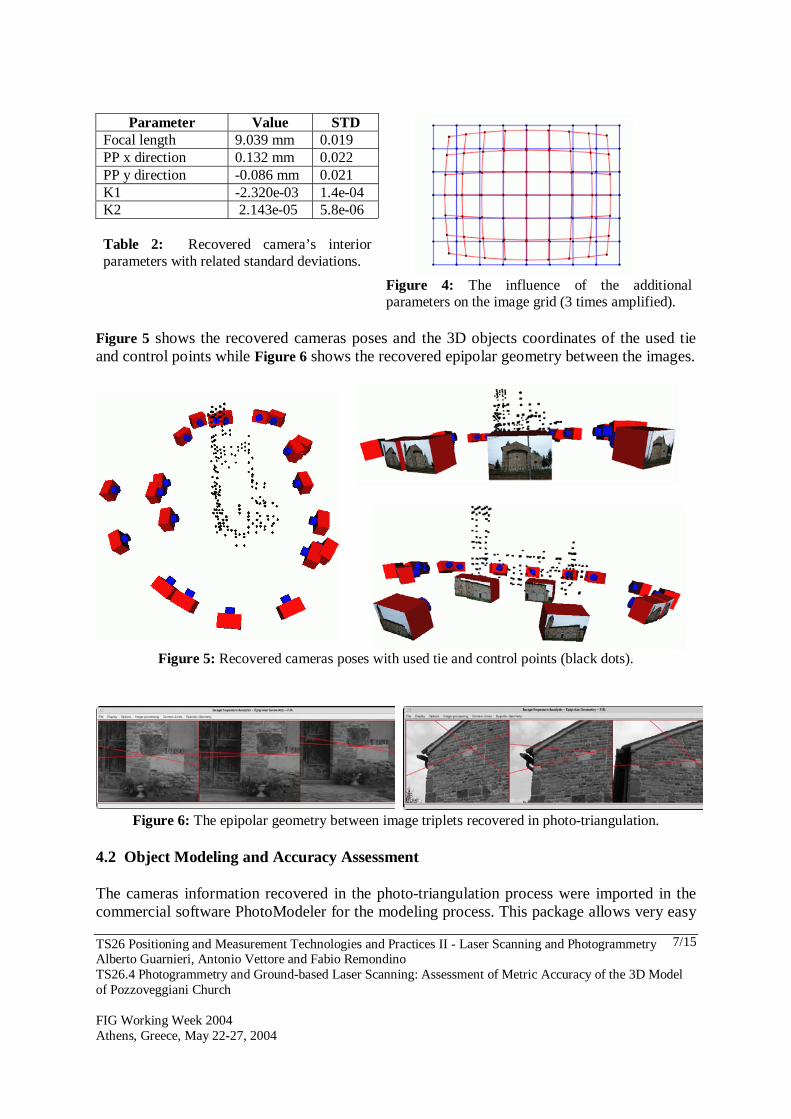
Parameter Value STD
Focal length 9.039 mm 0.019 PP x direction 0.132 mm 0.022 PP y direction -0.086 mm 0.021 K1 -2.320e-03 1.4e-04 K2 2.143e-05 5.8e-06 Table 2: Recovered camera’s interior parameters with related standard deviations.
Figure 4: The influence of the additional parameters on the image grid (3 times amplified).
Figure 5 shows the recovered cameras poses and the 3D objects coordinates of the used tie and control points while Figure 6 shows the recovered epipolar geometry between the images.
Figure 5: Recovered cameras poses with used tie and control points (black dots).
Figure 6: The epipolar geometry between image triplets recovered in photo-triangulation. 4.2 Object Modeling and Accuracy Assessment The cameras information recovered in the photo-triangulation process were imported in the commercial software PhotoModeler for the modeling process. This package allows very easy

TS26 Positioning and Measurement Technologies and Practices II - Laser Scanning and Photogrammetry Alberto Guarnieri, Antonio Vettore and Fabio Remondino TS26.4 Photogrammetry and Ground-based Laser Scanning: Assessment of Metric Accuracy of the 3D Model of Pozzoveggiani Church FIG Working Week 2004 Athens, Greece, May 22-27, 2004
8/15
image measurements and 3D objects reconstruction with simple clicks. The user can manually define lines, edges, curves and surfaces and the generated 3D model can then be exported for further visualization. The results of the modeling are presented in Figure 7 as wireframe or colored shaded model and in Figure 8 as textured model. An analysis of the recovered object coordinates with respect to some check points measured with the total station was also performed. 21 check points well distribuited all over the church were compared with the recovered object coordinates and the differences are reported in Table 3.
Analysis with respect to # RMS X (m) RMS Y (m) RMS Z (m) Control points 29 0.006 0.009 0.010 Check points 21 0.017 0.027 0.022
Table 3: Summary of control and check point analysis for the recovered object points.
Figure 7: Wireframe model including points and lines manually measured in PhotoModeler (upper
images). Colored shaded 3D model from different view points (lower images).
TS26 Positioning and Measurement Technologies and Practices II - Laser Scanning and Photogrammetry Alberto Guarnieri, Antonio Vettore and Fabio Remondino TS26.4 Photogrammetry and Ground-based Laser Scanning: Assessment of Metric Accuracy of the 3D Model of Pozzoveggiani Church FIG Working Week 2004 Athens, Greece, May 22-27, 2004
9/15
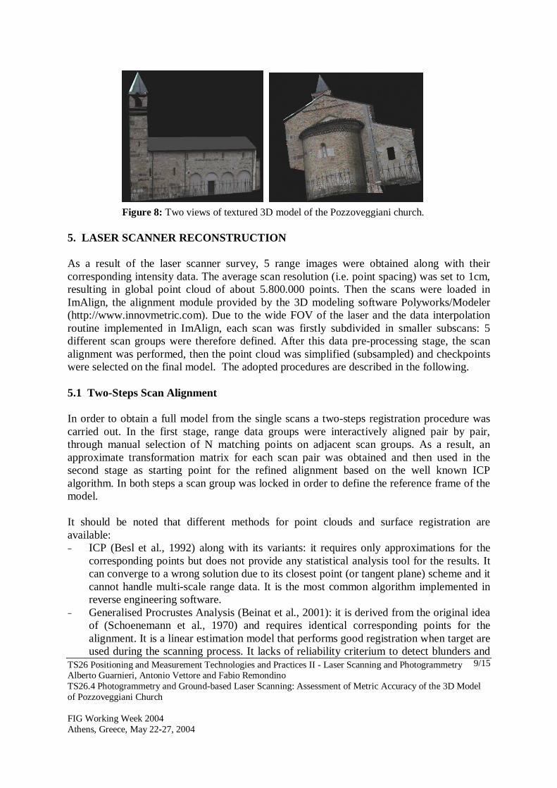
Figure 8: Two views of textured 3D model of the Pozzoveggiani church.
5. LASER SCANNER RECONSTRUCTION As a result of the laser scanner survey, 5 range images were obtained along with their corresponding intensity data. The average scan resolution (i.e. point spacing) was set to 1cm, resulting in global point cloud of about 5.800.000 points. Then the scans were loaded in ImAlign, the alignment module provided by the 3D modeling software Polyworks/Modeler (http://www.innovmetric.com). Due to the wide FOV of the laser and the data interpolation routine implemented in ImAlign, each scan was firstly subdivided in smaller subscans: 5 different scan groups were therefore defined. After this data pre-processing stage, the scan alignment was performed, then the point cloud was simplified (subsampled) and checkpoints were selected on the final model. The adopted procedures are described in the following. 5.1 Two-Steps Scan Alignment In order to obtain a full model from the single scans a two-steps registration procedure was carried out. In the first stage, range data groups were interactively aligned pair by pair, through manual selection of N matching points on adjacent scan groups. As a result, an approximate transformation matrix for each scan pair was obtained and then used in the second stage as starting point for the refined alignment based on the well known ICP algorithm. In both steps a scan group was locked in order to define the reference frame of the model. It should be noted that different methods for point clouds and surface registration are available: − ICP (Besl et al., 1992) along with its variants: it requires only approximations for the
corresponding points but does not provide any statistical analysis tool for the results. It can converge to a wrong solution due to its closest point (or tangent plane) scheme and it cannot handle multi-scale range data. It is the most common algorithm implemented in reverse engineering software.
− Generalised Procrustes Analysis (Beinat et al., 2001): it is derived from the original idea of (Schoenemann et al., 1970) and requires identical corresponding points for the alignment. It is a linear estimation model that performs good registration when target are used during the scanning process. It lacks of reliability criterium to detect blunders and
TS26 Positioning and Measurement Technologies and Practices II - Laser Scanning and Photogrammetry Alberto Guarnieri, Antonio Vettore and Fabio Remondino TS26.4 Photogrammetry and Ground-based Laser Scanning: Assessment of Metric Accuracy of the 3D Model of Pozzoveggiani Church FIG Working Week 2004 Athens, Greece, May 22-27, 2004
10/15
gross errors but it can handle global and simultaneous registrations and not only simple pairwise registrations.
− Least squares 3D surface matching (Gruen et al., 2004): it is a generalization of the least squares 2D image matching concept; it can handle any kind of 3D surface and it has good tools for accuracy and reliability checks. As non-linear estimation model, it requires good approximations of the unknowns.
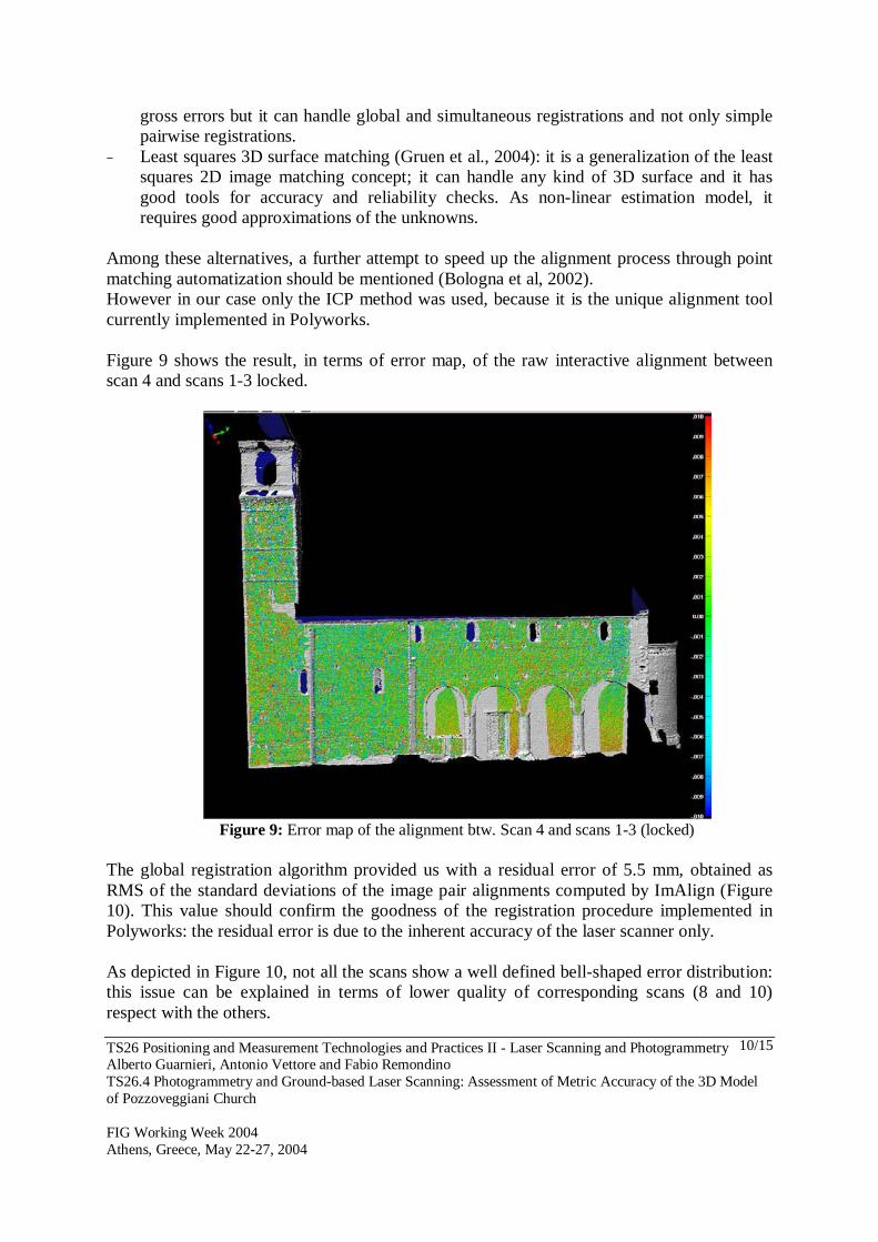
Among these alternatives, a further attempt to speed up the alignment process through point matching automatization should be mentioned (Bologna et al, 2002). However in our case only the ICP method was used, because it is the unique alignment tool currently implemented in Polyworks. Figure 9 shows the result, in terms of error map, of the raw interactive alignment between scan 4 and scans 1-3 locked.
Figure 9: Error map of the alignment btw. Scan 4 and scans 1-3 (locked)
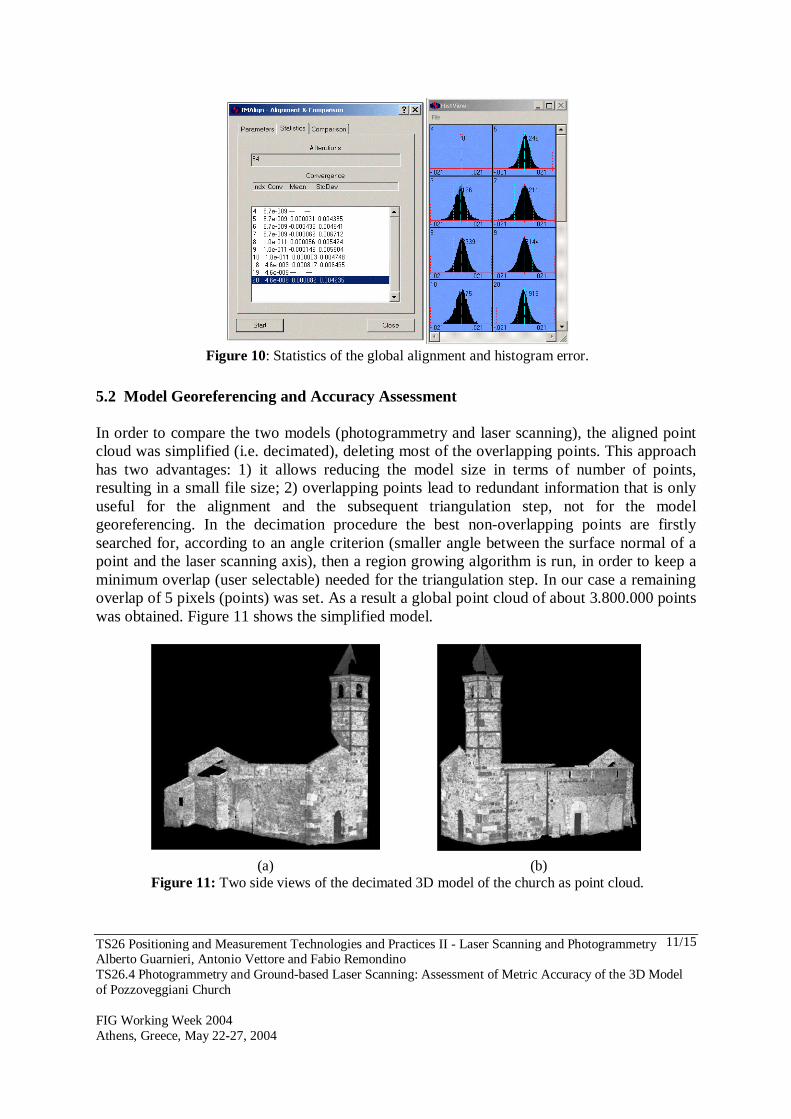
The global registration algorithm provided us with a residual error of 5.5 mm, obtained as RMS of the standard deviations of the image pair alignments computed by ImAlign (Figure 10). This value should confirm the goodness of the registration procedure implemented in Polyworks: the residual error is due to the inherent accuracy of the laser scanner only. As depicted in Figure 10, not all the scans show a well defined bell-shaped error distribution: this issue can be explained in terms of lower quality of corresponding scans (8 and 10) respect with the others.
TS26 Positioning and Measurement Technologies and Practices II - Laser Scanning and Photogrammetry Alberto Guarnieri, Antonio Vettore and Fabio Remondino TS26.4 Photogrammetry and Ground-based Laser Scanning: Assessment of Metric Accuracy of the 3D Model of Pozzoveggiani Church FIG Working Week 2004 Athens, Greece, May 22-27, 2004
11/15
Figure 10: Statistics of the global alignment and histogram error.
5.2 Model Georeferencing and Accuracy Assessment In order to compare the two models (photogrammetry and laser scanning), the aligned point cloud was simplified (i.e. decimated), deleting most of the overlapping points. This approach has two advantages: 1) it allows reducing the model size in terms of number of points, resulting in a small file size; 2) overlapping points lead to redundant information that is only useful for the alignment and the subsequent triangulation step, not for the model georeferencing. In the decimation procedure the best non-overlapping points are firstly searched for, according to an angle criterion (smaller angle between the surface normal of a point and the laser scanning axis), then a region growing algorithm is run, in order to keep a minimum overlap (user selectable) needed for the triangulation step. In our case a remaining overlap of 5 pixels (points) was set. As a result a global point cloud of about 3.800.000 points was obtained. Figure 11 shows the simplified model.
(a) (b)
Figure 11: Two side views of the decimated 3D model of the church as point cloud.
TS26 Positioning and Measurement Technologies and Practices II - Laser Scanning and Photogrammetry Alberto Guarnieri, Antonio Vettore and Fabio Remondino TS26.4 Photogrammetry and Ground-based Laser Scanning: Assessment of Metric Accuracy of the 3D Model of Pozzoveggiani Church FIG Working Week 2004 Athens, Greece, May 22-27, 2004
12/15
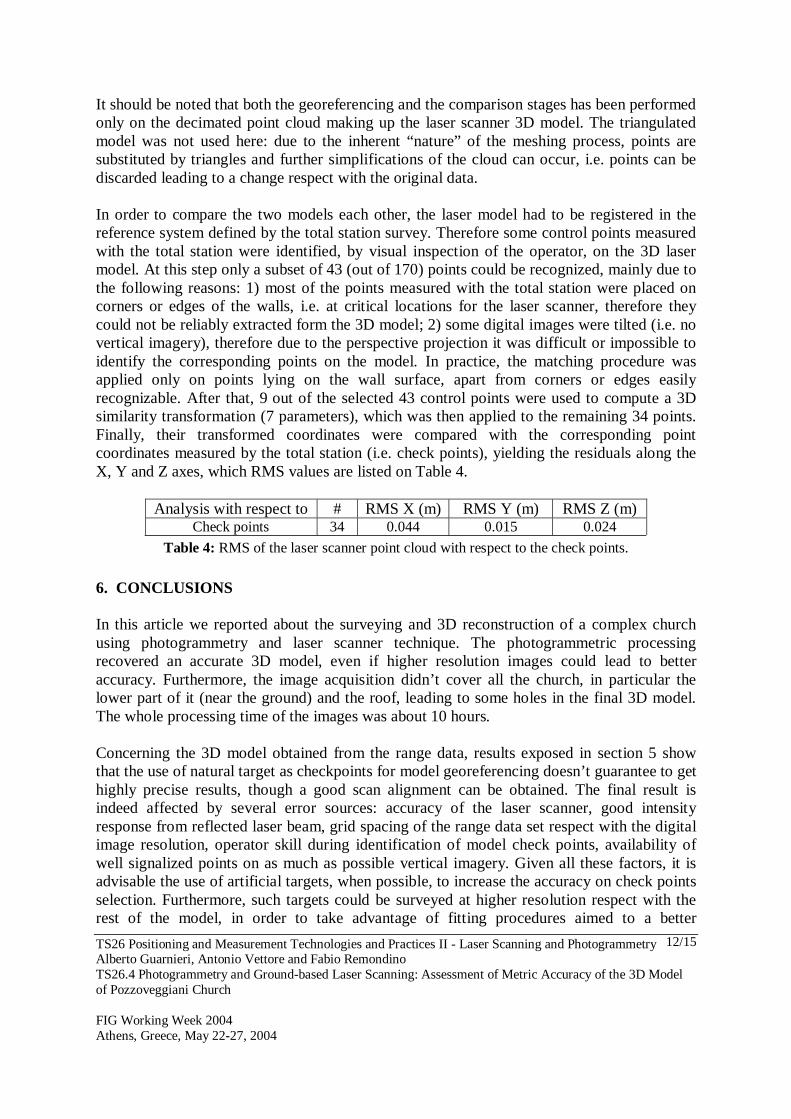
It should be noted that both the georeferencing and the comparison stages has been performed only on the decimated point cloud making up the laser scanner 3D model. The triangulated model was not used here: due to the inherent “nature” of the meshing process, points are substituted by triangles and further simplifications of the cloud can occur, i.e. points can be discarded leading to a change respect with the original data. In order to compare the two models each other, the laser model had to be registered in the reference system defined by the total station survey. Therefore some control points measured with the total station were identified, by visual inspection of the operator, on the 3D laser model. At this step only a subset of 43 (out of 170) points could be recognized, mainly due to the following reasons: 1) most of the points measured with the total station were placed on corners or edges of the walls, i.e. at critical locations for the laser scanner, therefore they could not be reliably extracted form the 3D model; 2) some digital images were tilted (i.e. no vertical imagery), therefore due to the perspective projection it was difficult or impossible to identify the corresponding points on the model. In practice, the matching procedure was applied only on points lying on the wall surface, apart from corners or edges easily recognizable. After that, 9 out of the selected 43 control points were used to compute a 3D similarity transformation (7 parameters), which was then applied to the remaining 34 points. Finally, their transformed coordinates were compared with the corresponding point coordinates measured by the total station (i.e. check points), yielding the residuals along the X, Y and Z axes, which RMS values are listed on Table 4.
Analysis with respect to # RMS X (m) RMS Y (m) RMS Z (m) Check points 34 0.044 0.015 0.024
Table 4: RMS of the laser scanner point cloud with respect to the check points.
6. CONCLUSIONS In this article we reported about the surveying and 3D reconstruction of a complex church using photogrammetry and laser scanner technique. The photogrammetric processing recovered an accurate 3D model, even if higher resolution images could lead to better accuracy. Furthermore, the image acquisition didn’t cover all the church, in particular the lower part of it (near the ground) and the roof, leading to some holes in the final 3D model. The whole processing time of the images was about 10 hours. Concerning the 3D model obtained from the range data, results exposed in section 5 show that the use of natural target as checkpoints for model georeferencing doesn’t guarantee to get highly precise results, though a good scan alignment can be obtained. The final result is indeed affected by several error sources: accuracy of the laser scanner, good intensity response from reflected laser beam, grid spacing of the range data set respect with the digital image resolution, operator skill during identification of model check points, availability of well signalized points on as much as possible vertical imagery. Given all these factors, it is advisable the use of artificial targets, when possible, to increase the accuracy on check points selection. Furthermore, such targets could be surveyed at higher resolution respect with the rest of the model, in order to take advantage of fitting procedures aimed to a better
TS26 Positioning and Measurement Technologies and Practices II - Laser Scanning and Photogrammetry Alberto Guarnieri, Antonio Vettore and Fabio Remondino TS26.4 Photogrammetry and Ground-based Laser Scanning: Assessment of Metric Accuracy of the 3D Model of Pozzoveggiani Church FIG Working Week 2004 Athens, Greece, May 22-27, 2004
13/15
identification of the target center. However, it should be noted that some laser scanners can show an unexpected behavior when dealing with retro-reflective targets, which leads to macroscopic measurement errors. Therefore great care must be taken in choosing the appropriate kind of target. The whole processing time of the range data images required 7-8 hours. Anyway this value should be considered as an estimate, since it can vary from model to model. Indeed it depends on several factors like: number of scans to be aligned, object shape complexity, availability of intensity data, scans provided as binary or ASCII files. In our case for example, range data were provided by Mensi as ASCII file, i.e. as sets of unorganized points. Therefore an appropriate routine was run in order to retrieve the information about the point normals and to convert the data in organized (interpolated) point clouds, as requested to be properly managed by Polyworks. Beside this, another very time consuming procedure was the identification on the aligned model of the checkpoints, as described in previous sections. Both modeling processes have their advantages and disadvantages, as demonstrated in the previous sections. A good solution could be the combination of the methods, as suggested in (Guidi et al., 2003), as each one has attributes and elements that complement one another. REFERENCES Beinat, A., Crosilla, F., 2001: Generalized Procrustes Analysis for size and shape 3-D object
reconstruction. In Gruen, Kahmen (Eds), V Optical 3-D Measurement Techniques, pp. 345-352, Vienna, Austria
Beraldin, J.A, Blais, F, et al., 2000: Active 3D sensing. Scuola Normale Superiore Pisa, Centro di Ricerche Informatiche per I Beni Culurali, Quaderni 10, 21 pp
Blais, F., 2003: A review of 20 years of range sensor development. Videometrics VII, Proc. of SPIE Electronic Imaging., Vol. 5013, pp. 62-76
Bologna R., Guarnieri A., Minchilli M., Vettore A., 2002: Automatic registration of 3D views, Proceedings of the ISPRS Comm. V Symposium “Close Range Imaging-Long-Range Vision”, 2-6 September, Corfù, Greece.
Chen, F., et al., 2000: Overview of three-dimensional shape measurement using optical methods. Optic. Eng., Vol. 39, pp. 10-22
El-Hakim S. F., 2001. 3D Modeling of Complex Environments. Videometrics and Optical Methods for 3D Shape measurement, Proceedings of SPIE , vol 4309.
Gartner, H., Lehle, P., Tiziani, H.J., 1995: New, high efficient, binary codes for structured light methods. SPIE Proceedings, Vol. 2599, pp. 4-13
Gruen, A., Akca, D., 2004: Least squares 3D surface matching. Int. Arch. of Photogrammetry and Remote Sensing, Vol. 34(5/W16), Dresden, Germany
Guidi G., Beraldin J.-A., Ciofi S., Atzeni C., 2003: Fusion of range camera and photogrammetry: a systematic procedure for improving 3D models metric accuracy. IEEE Trans. on Systems, Man, and Cybernetics.
Healey, G., Binford, T.O., 1987: Local Shape from Specularity. Proc. ICCV, London Horn, B.K.P., Brooks, M.J., 1989: Shape from Shading. MIT Cambridge Kender, J.R., 1978: Shape from Texture. Proc. DARPA IU Workshop
TS26 Positioning and Measurement Technologies and Practices II - Laser Scanning and Photogrammetry Alberto Guarnieri, Antonio Vettore and Fabio Remondino TS26.4 Photogrammetry and Ground-based Laser Scanning: Assessment of Metric Accuracy of the 3D Model of Pozzoveggiani Church FIG Working Week 2004 Athens, Greece, May 22-27, 2004
14/15
Maas, H.G., 1992: Robust Automatic Surface Reconstruction with Structured Light. Int. Archives of Photogrammetry and Remote Sensing, Vol. 24(B5), pp. 102-107
Minoru, A., Nakamura T., 1993: Cylindrical Shape from Contour and Shading without Knowledge of Lighting Conditions or Surface Albedo. IPSJ Journal, Vol. 34(5)
Meyers, D., et al., 1992: Surfaces from contours. ACM Transactions on Graphics, Vol. 11(3), pp.228–258
Remondino, F., 2003: 3D reconstruction of static human body with a digital camera. In El-Hakim, Gruen, Walton (Eds), Videometrics VII, Proc. of SPIE Electronic Imaging, Vol. 5013, pp. 38-45, Santa Clara, CA, USA
Sablatnig, R., Menard, C., 1997: 3D Reconstruction of Archaeological Pottery using Profile Primitives. Sarris N., Strintzis M.G. (Eds) Proc. of International Workshop on Synthetic-Natural Hybrid Coding and Three-Dimensional Imaging, pp. 93-96
Schoenemann, P.H., Carroll. R. M., 1970: Fitting one matrix to another under choice of a central dilation and a rigid motion. Psychometria, Vol. 35(2)
Sequeira V., Ng K., et al. 1999: Automated reconstruction of 3D models from real environments. ISPRS Journal for Photogrammetry and Remote Sensing, 54(1), pp. 1-22
Ulupinar F., Nevatia R., 1995: Shape from Contour: Straight Homogeneous Generalized Cylinders and Constant Cross Section Generalized Cylinders. Trans. PAMI, Vol. 17(2)
Wahl, F.M., 1984: A Coded Light Approach for 3-Dimensional Vision. IBM Research Report, RZ 1452
Winkelbach, S., Wahl, F.M., 2001: Shape from 2D Edge Gradient. Pattern Recognition, Lecture Notes in Computer Science 2191, Springer
BIOGRAPHICAL NOTES Alberto Guarnieri graduated in 1998 at the Faculty of Electronic Engineering, University of Padua, Italy. With a dissertation on “ Mobile Mapping Systems for GIS applications”. Since 2002 he is a PhD Student by CIRGEO (Interdept. Research Center for Cartography, Photo-grammetry, Remote Sensing and GIS, University of Padua, Italy). The topic of his work is the 3D modeling with ground-based laser scanning, both for long-range and close-range applications. He is interested in the development of low cost mobile mapping systems, as well. Fabio Remondino graduated in 1998 in Environmental Engeneering at the T.U. of Milan, Italy. Since 2000 he is a PhD student at the Institute of Geodesy and Photogrammetry (ETH Zurich, Switzerland). The topic of his work is 'Character Animation and Understanding from Sequences of Images' but he also working on the 3D Reconstruction of the Bamiyan Buddhas, Afghanistan. His main interests are image sequences analisys, 3D objects reconstruction, camera calibration and orientation. Currently he is also serving as webmaster of the International Society of Photogrammetry and Remote Sensing (ISPRS). Antonio Vettore graduated in Civil Engineering, University of Padua in 1976 and then in 1987 he received the PhD in Geodetic and Tophographic Sciences, University of Bologna. Since 2004 he is Full Professor in Topography at the University of Padua, where he is teaching Topography and Photogrammetry at the Faculty of Agricultural Sciences and at the

TS26 Positioning and Measurement Technologies and Practices II - Laser Scanning and Photogrammetry Alberto Guarnieri, Antonio Vettore and Fabio Remondino TS26.4 Photogrammetry and Ground-based Laser Scanning: Assessment of Metric Accuracy of the 3D Model of Pozzoveggiani Church FIG Working Week 2004 Athens, Greece, May 22-27, 2004
15/15
Faculty of Engineering. He is a member of the two SIFET working groups "Movement and control" and "Advanced analysis methods in geodesy and mapping". He has published more than 80 papers in the fields of topography and photogrammetry. Visiting research (1999) at the Virtual Information Technology Group, Institute for Information Technology, National Research Council of Canada (NRC), he is also member of the Working Group WG 5.3, IAG, "Kinematic and Integrated Positioning Systems". He is the head of the Interdept. Research Center CIRGEO, by the University of Padua, which he founded in 2000. CONTACTS Alberto Guarnieri CIRGEO – Interd. Research Center for Cartography, Photogrammetry, Remote Sensing and GIS University of Padua 35020 Legnaro (Padova) ITALY Tel. + 39 049 827 2688 Email: [email protected] Fabio Remondino Institute of Geodesy and Photogrammetry ETH Hoenggerberg 8093 Zurich SWITZERLAND Tel. + 41 1 633 3058 Fax + 41 1 633 1101 Email: [email protected] Web site: http://www.photogrammetry.ethz.ch Prof. Antonio Vettore CIRGEO – Interdept. Research Center for Cartography, Photogrammetry, Remote Sensing and GIS University of Padua 35020 Legnaro (Padova) ITALY Tel. + 39 049 827 2688 Fax + 39 049 827 2686 Email: [email protected]