physical layer simulations of the ieee 802.11b wireless lan ...1029318/...the report begins with a...
TRANSCRIPT

Magnus Lindgren
Physical Layer Simulations of the IEEE 802.11b Wireless LAN-standard
2001:066
MASTER'S THESIS
Civilingenjörsprogrammet Elektroteknik
Institutionen för SystemteknikAvdelningen för Signalbehandling
2001:066 • ISSN: 1402-1617 • ISRN: LTU-EX--01/066--SE

Physical Layer Simulations of the IEEE 802.11bWireless LAN-standard
Magnus [email protected]
12th February 2001
a brand new world

Abstract
The purpose of this report is to investigate the coexisting possibilities be-tween Wireless Local Area Networks (W-LAN), defined by IEEE 802.11b,and BlueTooth at the unlicenced ISM band. The ISM band is situated at2.4000-2.4835 GHz and there are several applications, for example Blue-Tooth, using this spectrum.
A physical layer simulator of the W-LAN (defined by IEEE 802.11b)has been constructed in Matlab in order to simulate the radio interface.Both the 5.5 Mbps and the 11 Mbps modes have been implemented, butthe slower basic and enhanced access rates, i.e. 1 Mbps and 2 Mbps, arenot implemented. According to the IEEE specification the W-LAN shouldtransmit the data in frames, but the preamble and the header are not im-plemented. Only the part which contains the data to be transmitted isimplemented. So, the synchronisation issue and other issues, like redun-dancy check, are not studied in this report.
The performance of the W-LAN when it is interfered by another W-LAN (also IEEE 802.11b) at adjacent channels is investigated. An existingBlueTooth physical layer simulator has been used to evaluate the W-LAN’sperformance in terms of bit error rate when interfered by a BlueTooth unit.The performance degradation of the BlueTooth system when interfered ofa W-LAN is also simulated.
The simulations show that both wireless systems can coexist with eachother in the ISM band, but they both experience performance degradation.At a bit error rate of 10−5 (corresponding to the W-LAN sensitivty level)for the W-LAN the Carrier-to-Interferer (C/I) ratio is 4 dB with BlueToothas interferer. At a bit error rate of 10−3 (corresponding to the BlueToothsensitivity level) for the BlueTooth system the C/I ratio is 4 dB with a W-LAN as interferer. So, both systems seem to require the same C/I ratio toobtain a bit-error rate corrresponding to their respective sensitivity levels.
2

Contents1 Introduction 7
1.1 Spread spectrum . . . . . . . . . . . . . . . . . . . . . . . . 71.2 ISM band . . . . . . . . . . . . . . . . . . . . . . . . . . . . 71.3 Introduction to the report . . . . . . . . . . . . . . . . . . . 8
2 BlueTooth 8
3 W-LAN 93.1 IEEE 802.11 standard . . . . . . . . . . . . . . . . . . . . . 10
3.1.1 IEEE 802.11 Physical Layer . . . . . . . . . . . . . . 103.1.2 IEEE 802.11 Medium Access Control Layer . . . . . 11
4 IEEE 802.11b Physical Layer 114.1 PPDU Frame . . . . . . . . . . . . . . . . . . . . . . . . . . 124.2 Long PLCP . . . . . . . . . . . . . . . . . . . . . . . . . . . 12
4.2.1 Long Sync . . . . . . . . . . . . . . . . . . . . . . . . 134.2.2 Long SFD . . . . . . . . . . . . . . . . . . . . . . . . 134.2.3 Long Signal . . . . . . . . . . . . . . . . . . . . . . . 134.2.4 Long Service . . . . . . . . . . . . . . . . . . . . . . 144.2.5 Long Length . . . . . . . . . . . . . . . . . . . . . . 144.2.6 Long CRC . . . . . . . . . . . . . . . . . . . . . . . 14
4.3 Short PLCP . . . . . . . . . . . . . . . . . . . . . . . . . . . 154.3.1 Short Sync . . . . . . . . . . . . . . . . . . . . . . . 154.3.2 Short SFD . . . . . . . . . . . . . . . . . . . . . . . 154.3.3 Short Signal . . . . . . . . . . . . . . . . . . . . . . . 16
4.4 Scrambler . . . . . . . . . . . . . . . . . . . . . . . . . . . . 164.5 Modulation . . . . . . . . . . . . . . . . . . . . . . . . . . . 16
4.5.1 Modulation for 1 and 2 Mbps . . . . . . . . . . . . . 164.5.2 Spreading codes and CCK Modulation for 5.5 and
11 Mbps . . . . . . . . . . . . . . . . . . . . . . . . . 164.5.3 CCK modulation for 5.5 Mbps . . . . . . . . . . . . 174.5.4 CCK modulation for 11 Mbps . . . . . . . . . . . . . 184.5.5 PBCC Modulation for 5.5 and 11 Mbps . . . . . . . 19
4.6 Spectrum mask . . . . . . . . . . . . . . . . . . . . . . . . . 214.7 Sensitivity . . . . . . . . . . . . . . . . . . . . . . . . . . . . 214.8 Channel placement . . . . . . . . . . . . . . . . . . . . . . . 21
5 Physical Layer Simulator 225.1 Modulation . . . . . . . . . . . . . . . . . . . . . . . . . . . 235.2 Pulse shaping . . . . . . . . . . . . . . . . . . . . . . . . . . 235.3 Sample point . . . . . . . . . . . . . . . . . . . . . . . . . . 235.4 Channel . . . . . . . . . . . . . . . . . . . . . . . . . . . . . 245.5 Lowpass filtering . . . . . . . . . . . . . . . . . . . . . . . . 24
3

6 Simulations and results 256.1 Spectrum of the implemented transmitter . . . . . . . . . . 256.2 Sensitivity of the implemented receiver . . . . . . . . . . . . 266.3 802.11b simulations . . . . . . . . . . . . . . . . . . . . . . . 28
6.3.1 802.11b disturbed by another 802.11b . . . . . . . . 296.3.2 802.11b disturbed by BlueTooth . . . . . . . . . . . 29
6.4 BlueTooth simulation . . . . . . . . . . . . . . . . . . . . . 306.4.1 BlueTooth disturbed by 802.11b . . . . . . . . . . . 30
6.5 Combining results . . . . . . . . . . . . . . . . . . . . . . . 32
7 Conclusions 327.1 Conditions for the simulations . . . . . . . . . . . . . . . . . 327.2 Discussion of the obtained results . . . . . . . . . . . . . . . 337.3 Limitations and future work . . . . . . . . . . . . . . . . . . 34
A Appendix 36
4
AcknowledgementI would like to thank Jonas Strandell, my tutor at A Brand New World, BoMagnusson, A Brand New World, and Frank Sjoberg, my tutor at LuleaUniversity of Technology, for their help with this project.
5

List of AcronymsACK = ACKnowledgment packetAWGN = Additive White Gaussian NoiseBER = Bit Error RateBT = BlueToothCCK = Complementary Code KeyingC/I = Carrier-to-InterfererCRC = Cyclic Redundancy CheckCSMA/CA = Carrier Sense Multiple Access with Collision AvoidanceCTS = Clear To SendDBPSK = Differential Binary Phase Shift KeyingDSSS = Direct Sequence Spread SpectrumDQPSK = Differential Quadrature Phase Shift KeyingETSI = European Telecommunications Standards InstituteFCC = Federal Communications Commission (USA)FCS = Frame Check SequenceFEC = Forward Error CorrectionFER = Frame Error RateFHSS = Frequency Hopping Spread SpectrumHR/DSSS = High Rate Direct Sequence Spread SpectrumIR = Infra RedISM band = Industrial, Scientific, and Medical- bandMAC = Medium Access ControlMKK = Radio Equipment Inspection and Certification Institute (Japan)OFDM = Orthogonal Frequency Division MultiplexingPBCC = Packet Binary Convolutional CodePHY = Physical LayerPLCP = Physical Layer Convergence ProcedurePMD = Physical Medium DependentPPDU = PHY Protocol Data UnitsPSDU = PLCP Service Data UnitsPTS = Post och Tele Styrelsen (Sweden)RTS = Ready To SendSFD = Start Frame DelimiterU-NII band = Unlicenced National Information Infrastructure -bandW-LAN = Wireless Local Area Network
6

1 IntroductionThe purpose of this Master Thesis is to investigate the possibility for Wire-less Local Area Network (W-LAN), defined by standard IEEE 802.11b [3,4], to coexist with BlueTooth (BT) [2] in the unlicenced band at 2.45 GHz.The IEEE 802.11b is a standard already in use (and expanding) and withthe predicted very big market for BlueTooth, it is critical to investigatethe coexistance between these systems. In this report the focus is on howwell IEEE 802.11b handles other IEEE 802.11b and BlueTooth interferers,but it also includes a small part on how well BlueTooth handles an IEEE802.11b W-LAN as an interferer. To be able to evaluate this issue an IEEE802.11b simulator were developed in Matlab, and with help of an alreadyexisting BlueTooth simulator, constructed by Jonas Strandell at A BrandNew World in Sweden AB, this problem could be investigated.
1.1 Spread spectrumBoth the W-LAN and the BlueTooth system uses spread spectrum tech-nique, i.e. the modulation uses a large bandwidth when transmitting atthe ISM band. The spread spectrum technique [1] was developed duringthe 1940’s by the US military, mainly because of its resistance to jamming.There are essentially two different spread spectrum techniques, frequencyhopping and direct sequence spread spectrum.
The frequency hopping technique does what the name says, it changesthe transmitting frequency within a certin bandwidth in a psuedorandommanner. There can be very many different possible narrow frequency bandsto transmit in and an enemy would have trouble to eavesdrop the trans-mission. In public use the advantage is that if there is a jammer at aspecific frequency it will not affect the whole transmission, only lower theperformance of the system. Of course the receiver must know the frequencypsuedorandom hop pattern to be able to receive the signal successfully.
The direct sequence technique spreads the whole signal to be transmit-ted over a large bandwidth with a PN code consisting of +1 and -1 in apsuedorandom manner. In the receiver the received signal is despread withthe same PN code and the original signal is received. When the receivedsignal is despreaded all narrowband jamming sources are spread over alarge bandwidth, so also this technique is also resistant to jammers.
1.2 ISM bandThe use of the radio spectrum is regulated in every country by a regula-tor, in Sweden it is PTS, in Europe it is ETSI, in Japan it is MKK, andin North America it is FCC. These regulators defines every allocation ofradio bandwidth, e.g. TV, radio, telecommunications and military com-munications. They have also allocated some specific frequency bands to beused in a more flexible way, mainly to short range radio communications.
7

These bands are unlicenced, which means that a user can use them with-out having to register or to pay licence feas. In order to avoid abuse ofthese unlicenced bands a set of rules has been formed. These rules specifythings such as, maximum transmit power, out of band emissions, spreadspectrum, etc. The rules varies for each specific unlicenced band. Prod-ucts must be certified to conform to the rules of the intended band to beallowed to transmit.
The ISM band was originally designed and reserved for Industrial, Sci-entific, and Medical use, and is (almost) allocated at the same frequnciesall over the world. It is located at 2.4000-2.4835 GHz (US, Japan, andalmost the whole of Europe) and has been released to be an unlicencedband. To be allowed to transmit in this band, spread spectrum modula-tion must be used. Many products, such as W-LAN, BlueTooth, and alsomicrowave ovens, use this band. This creates a disturbed environment inwhich the products must be able to coexist.
1.3 Introduction to the reportThe report begins with a breif introduction to BlueTooth in Chapter 2 andW-LANs in Chapter 3. The Physical Layer (PHY) of the IEEE 802.11bstandard (W-LAN) is described more detailed in Chapter 4. All buildingblocks of the developed IEEE 802.11b PHY simulator are described. Theconditions of the simulations, and the simulations and results are presentedin Chapter 6. Finally, conclusions are drawn from the presented results andfuture work is suggested.
2 BlueToothIn this chapter BlueTooth is described briefly, the main part of the ma-terial was found in a whitepaper about BlueTooth [2]. The developmentof BlueTooth started in 1994 when Ericsson Mobile Communications ini-tiated a study in order to find a low power and a low cost radio interface.The intended use was between mobile phones and its accessories in orderto replace cables between these products. They had hard requirementsregarding size, capacity, power consumption, price and global uniformity.Ericsson soon realised that they needed partners to develop this techniqueand in 1998 a Special Interest Group (SIG) was formed with Intel, IBM,Toshiba and Nokia. Today more than 1300 companies are members of theSIG and are therefore licensed to manufacture BlueTooth devices.
BlueTooth’s purpose has expanded over the years, from cable replace-ment to beeing able to create small radio LANs. The range of a BT productis 10 m or less in the case with 1 mW maximum transmitted power, andit is 100 m or less with 100 mW maximum transmitted power. Whenevertwo, or more, BT products come in range of each other they can set up anad-hoc connection.
8

Ad-hoc connectivity differs from cellular radio architecture in whichterminals are connected to a base station. A base station controls theportable units and connects them to a wired net, i.e. the portable unitscan be connected to each other through a base station or base stations. Inan ad-hoc system there is no difference between radio units, that is, thereare no base stations. There is no wired infrastructure to connect differentportable units. The idea is that the radio units should be able to operateand communicate directly with each other. One could say that the unitsshould be able to communicate by them self, without the control of basestations. The units will provide the coverage and backbone of the specificsystem. One example of an ad-hoc radio system is a walky-talky system.
When BT products creates an ad-hoc connection, one of the BT prod-ucts will become the master and the other one, or ones, will be slaves.There is room for up to 7 slaves under one master. The master and itsslaves formes a piconet. Many piconet connections coexisting in the samearea are called scatter nets or scatter ad-hoc nets. There can only be onemaster which controls its slaves radio traffic to prevent packet collisions.
Before a BT device has joined a piconet it is in standby mode, whichmeans that it ”wakes up” every 1.28 seconds to listen for messages.
BT uses Frequency Hopping Spread Spectrum modulation at the ISMband. The hopping rate is up to 1600 hops per second depending on whichtype of data packets that are transmitted. There are 79 possible 1 MHzwide channels at the ISM band that a BT application is hopping betweenin an psuedo random pattern.
3 W-LANA Wireless Local Area Network consists of one or more access points whichis connected to a wired LAN. The mobile wireless clients get access to thewired LAN through the access points. This calls for a different controland function of the network, the access points and clients mainly consistof two parts, a radio modem and a controller. The radio modem is calledPhysical Layer (PHY) and the control function is called Medium AccessControl (MAC).
The Physical Layer handles the transmission of data between the accesspoint and the wireless client, i.e. the PHY handles everything from theantenna to the received and demodulated decoded bits. The PHY Layeris controlled by the MAC Layer.
The Medium Access Control layer controls and regulates the usage ofthe medium with a channel access mechanism. This mechanism dividesthe use of the radio channel between different users, regulating the userstransmissions and avoiding collisions between data packets.
9

3.1 IEEE 802.11 standardIn the following sections the different alternatives of Physical Layers andthe Medium Access Control Layer of the IEEE 802.11 standard are de-scribed.
3.1.1 IEEE 802.11 Physical Layer
The Physical Layer handles the transmission of data between nodes. IEEE802.11 specifies five different Physical Layers (e.g. different modulationtechniques)
• Direct Sequence Spread Spectrum (DSSS)
• Frequency Hopping Spread Spectrum (FHSS)
• Infrared (IR)
• High Rate Direct Sequence Spread Spectrum (HR/DSSS)
• Orthogonal Frequency Division Multiplexing (OFDM)
DSSS is a modulation technique where the ”data” is multiplied witha Spreading Sequence (PN Sequence), of much higher frequency than thedata, which ”spreads” the signal over a wider bandwidth. A bandwidthof 25 MHz is used, which makes room for three different non-overlappinglocations of the DSSS spectrum within the ISM band. The bit rate for thistechnique is 1 or 2 Mbps.
FHSS is a modulation technique where the data packets are transmittedin different frequency channels according to a psuedo random frequencyhopping scheme. The transmissions are spread over frequency with time,this way the data is spread over a large bandwidth. In this case there are79 channels each 1 MHz wide within the ISM band and a hop rate of 2.5hops per second is used. Also for this technique, the bit rate is 1 or 2Mbps.
IR is a modulation technique where the data is sent with infrared light(wavelength 850 to 950 nm) and requires line of sight. This technique isintended for indoor use only.
HR/DSSS occupies about the same spectrum as DSSS and it uses Com-plementary Code Keying (CCK) [4] as modulation. As the name implies,the data rate is higher than for the original DSSS, 5.5 to 11 Mbps instead of1 to 2 Mbps. But the higher bit rates requires higher SNR, which reducesthe range. It is backward compatible with the original DSSS system. TheIEEE 802.11b standard uses this CCK modulation and operates in the ISMband. CCK modulation is based on complementary codes and was choosenover other modulations for its superior performance regarding multipathand its good autocorrelation and cross-correlation properties.
OFDM is a modulation technique which uses several orthogonal sub-carriers to send symbols parallel with each other. This way the symboltime can be longer to counteract delay spread and still achieve high bit
10

rates. The bit rate and signal strength can be adapted to get maximumperformance in the system, giving the good subcarriers more bits and feweron the bad ones. The main drawbacks of an OFDM system are the vulner-ability to frequency offsets and synchronization errors. The IEEE 802.11astandard uses OFDM modulation and operates in the U-NII band (Unli-cenced National Information Infrastructure) allocated at 5 GHz, and thebit rate is up to 54 Mbps. This standard is very similar to ETSI’s Hiper-LAN II standard [8].
3.1.2 IEEE 802.11 Medium Access Control Layer
The Medium Access Control layer controls the transmissions and avoidscollisions between data packets. The IEEE 802.11 standard specifies a Car-rier Sense Multiple Access with Collision Avoidance (CSMA/CA) protocolas channel access mechanism. When a node wants to transmit a packet itfirst listens to ensure that no other node is transmitting. If the channel isfree, the node transmits its packet. Otherwise a random ”backoff factor”is chosen to determine the amount of time the node must wait until it canlisten to hear if the channel is free. When the backoff counter reaches zeroand the channel is clear the node transmits its packet. This minimisescollision between packets since the probability for two nodes to choose thesame backoff factor is small. This is needed because a transmitting nodecannot hear if any other node is transmitting since its own signal will drownany other signal arriving at the same time. Whenever a packet is to betransmitted the transmitting node first sends out a Ready To Send (RTS)packet containing information on the length of the packet. If the receivingnode hears the RTS, it will respond with a short Clear To Send (CTS)packet. After this exchange (handshake), the transmitting node sends itspacket. When a packet is received successfully the receiving node respondswith an ACKnowledgement (ACK) packet. A Cyclic Redundancy Check(CRC) is used to determine if a packet is received successfully. This back-and-forth handshaking is necessary to avoid the ”hidden node” problem.
The hidden node problem occurs when node A can hear node B but notnode C, and node C can hear node B but not node A. The problem can beseen in Figure 1. Consequently, node B can hear them both but node Aand C do not know that the other one exist. Node C is transmitting datato node B and node A want to start to transmit data to node B. Whennode A sends its RTS packet to node B, node B will not hear, or at leastnot respond, node A’s RTS packet. This way the hidden node problem issolved.
4 IEEE 802.11b Physical LayerSince the focus of this project is to develop a Physical Layer Simulatorbased on the IEEE 802.11b High Rate Direct Sequence Spread Spectrum
11

����A
-�Range of Node A
����B
-� Range of Node B
����C
-� Range of Node C
Figure 1: The Hidden Node Problem. Node A can not hear Node C and viceversa, both Node A and C can hear Node B, and Node B can hear both Node Aand C. The Hidden Node Problem occurs when Node A and Node C both want totransmitt data to Node B at the same time.
(HR/DSSS) specification [3], [4], a brief discription of the building blocksof the Physical Layer are described in the following sections.
4.1 PPDU FrameThe PHY Protocol Data Units (PPDU) frame contains all the necessarysynchronisation information etc. to be able to successfully receive the data.There are two different headers and preambles defined in the IEEE 802.11bstandard: the Long Physical Layer Convergence Procedure (Long PLCP)and the Short PLCP. The Long PLCP interoperates with the ”older” 1and 2 Mbps DSSS specification. The Short PLCP is optional and is in-tended for applications when maximum throughput is desired and wheninteroperability with other equipment, which is not using Short PLCP, isnot in consideration. The PLCP Service Data Units (PSDU) field con-tains the data that should be transmitted. This field can be modulatedwith four diffrent rates, 1 Mbps, 2 Mbps, 5.5 Mbps or 11 Mbps. In the 1or 2 Mbps choise the modulation are 1 Mbps DBPSK Barker or 2 MbpsDQPSK Barker, respectively. In the 5.5 or 11 Mbps choise the modula-tion is either CCK or the optional PBCC. These techniques are furtherdescribed in Section 4.5. A PPDU frame consist of one PLCP Preamble,one PLCP Header, and one PSDU, as can be viewed in Table 1.
PLCP Preamble PLCP Header PSDU144 (or 72) bits 48 bits variable # of bits
Table 1: Building blocks of a PPDU frame.
4.2 Long PLCPThe building blocks of the Long PLCP Preamble can be seen in Table 2,and the building blocks of the Long PLCP Header are shown in Table 3.When using the Long PLCP, Preamble and Header are both modulated
12
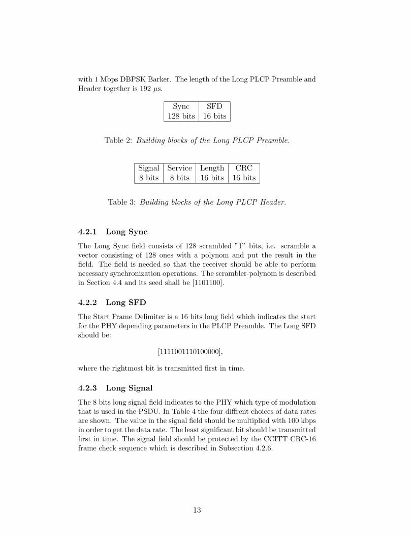
with 1 Mbps DBPSK Barker. The length of the Long PLCP Preamble andHeader together is 192 µs.
Sync SFD128 bits 16 bits
Table 2: Building blocks of the Long PLCP Preamble.
Signal Service Length CRC8 bits 8 bits 16 bits 16 bits
Table 3: Building blocks of the Long PLCP Header.
4.2.1 Long Sync
The Long Sync field consists of 128 scrambled ”1” bits, i.e. scramble avector consisting of 128 ones with a polynom and put the result in thefield. The field is needed so that the receiver should be able to performnecessary synchronization operations. The scrambler-polynom is describedin Section 4.4 and its seed shall be [1101100].
4.2.2 Long SFD
The Start Frame Delimiter is a 16 bits long field which indicates the startfor the PHY depending parameters in the PLCP Preamble. The Long SFDshould be:
[1111001110100000],
where the rightmost bit is transmitted first in time.
4.2.3 Long Signal
The 8 bits long signal field indicates to the PHY which type of modulationthat is used in the PSDU. In Table 4 the four diffrent choices of data ratesare shown. The value in the signal field should be multiplied with 100 kbpsin order to get the data rate. The least significant bit should be transmittedfirst in time. The signal field should be protected by the CCITT CRC-16frame check sequence which is described in Subsection 4.2.6.
13

Bit choise Bit choise Rate(Hex) (Binary) (Mbps)X’0A’ 00001010 1X’14’ 00010100 2X’37’ 00110111 5.5X’6E’ 01101110 11
Table 4: The Signal fields data rate choices.
4.2.4 Long Service
Three bits in the Service field support the high rate extension, bit b2, b3,and b7, as can be seen in Table 5. Bit b2 indicates whether the transmitfrequency and symbol clocks are derived from the same oscillator, bit b3indicates which modulation method which is used, and bit b7 is used withthe Length field if necessary. All other bits (b0, b1, b4, b5, b6) shall beset to 0. The leftmost bit (b0) should be transmitted first in time, andthe Service field should be protected by the CCITT CRC-16 frame checksequence which is described in Subsection 4.2.6.
b0 b1 b2 b3 b4 b5 b6 b7
Res Res Locked Mod. selec- Res Res Res LengthClocks Bit tion Bit Exten-0 = not 0 = CCK tion Bit
1 = locked 1 = PBCC
Table 5: The Service field.
4.2.5 Long Length
The Length field should be an unsigned 16 bits integer (calculated in octets)that indicates the number of microseconds required to transmit/receive thePSDU. With data rates over 8 Mbps there can be an ambiguity when aninteger describes how many octets that has been transmitted. If so, theLength Extention Bit in the Service field should be used. The least signif-icant bit should be tranmitted first in time. The Length field should beprotected by the CCITT CRC-16 frame check sequence which is describedin Subsection 4.2.6.
4.2.6 Long CRC
The Cyclic Redundacy Check (CCITT CRC-16 FCS) should be the ’1’-complement to the reminder that has been generated by modulo 2 division
14

of the fields to be protected by the polynom:
x16 + x12 + x5 + 1
The processing of the protected bits take place in transmit order and theCRC routine should be done before scrambling of the data bits. The Signal,Service, and Length fields should all be protected by the CCITT CRC-16frame check sequence together, i.e. run all fields to be protected throughthe CRC routine and put the result in the CRC field.
4.3 Short PLCPThe building blocks of the Short PLCP Preamble can be seen in Table 6,and the building blocks of the Short PLCP Header is the same as for theLong PLCP Header, which can be viewed in Table 3. The Short PLCPPreamble is modulated with 1 Mbps Barker and the Header is modulatedwith 2 Mbps DQPSK Barker. The PSDU is modulated with either 2 MbpsDQPSK Barker, 5.5 or 11 Mbps CCK. The length of the Short PLCPPreamble and Header together is 96 µs.
Sync SFD56 bits 16 bits
Table 6: Building blocks of the Short PLCP Preamble.
Only the fields which are different from their Long versions are de-scribed below.
4.3.1 Short Sync
The Short Synchronisation field consists of 56 scrambled ”0” bits. Theseed to the scrambler shall be [0011011]. The scrambler is described inSection 4.4.
4.3.2 Short SFD
The Short SFD field consists of the time reverse of the Long PLCP SFD.
[0000110001011111],
where the rigthmost bit is to be transmitted first in time. When the ShortSFD is the time reverse of the Long SFD a receiver not configured to usethe shorter PLCP Preamble and Header will not detect this SFD.
15

4.3.3 Short Signal
The Short Signal field have three diffrent choises of data rates, 2, 5.5, and11 Mbps, which are shown as the three lower alternatives in Table 4. Thevalue in the signal field should be multiplied with 100 kbps in order to getthe data rate. The least significant bit should be transmitted first in time.The signal field should be protected by the CCITT CRC-16 frame checksequence.
4.4 ScramblerThe polynomial G(z) = z−7+z−4+1 should be used to scramble/descrambledata bits in the High Rate mode. The data is scrambled before modula-tion and descrambled after demodulation. The scrambler shall be initiatedwith the proper seed described in Subsection 4.2.1 for the Long PLCP andin Subsection 4.3.1 for the Short PLCP.
4.5 ModulationThere are four diffrent modulation formats and data rates specified forIEEE 802.11b High Rate PHY. The basic access rate is 1 Mbps and isbased on DBPSK and the enhanced access rate is 2 Mbps and is basedon DQPSK. The extended Direct Sequence specification (802.11b) definestwo additional data rates, the high rate access rates for 5.5 and 11 Mbpsbased on Complementary Code Keying (CCK). There is also an optionalPacket Binary Convolutional Code mode (PBCC), which uses a 64-statebinary convolutional code (BCC) and the data rate for this modulation is5.5 or 11 Mbps. Systems implementing PBCC must support CCK in orderto be interoperable with other 802.11b W-LAN systems.
4.5.1 Modulation for 1 and 2 Mbps
The basic access rate based on DBPSK is defined in Table 7 and theenhanced access rate based on DQPSK is defined in Table 8. The PN codesequence for both 1 and 2 Mbps is the following 11-chip Barker sequence:
[+1,−1,+1, +1,−1, +1, +1, +1,−1,−1,−1], (1)
where the leftmost chip is to be transmitted first in time.The first chip should be aligned exactly with the start of a symbol and
the symbol should be exactly 11 chips long.
4.5.2 Spreading codes and CCK Modulation for 5.5 and 11Mbps
Complementary Code Keying [4] is a kind of Direct Sequence Spread Spec-trum modulation where the information lies in the spreading code. The
16

Bit input Phase change (+jω)0 01 π
Table 7: 1 Mbps DBPSK
Dibit pattern (d0,d1) Phase change (+jω)d0 is first in time
00 001 π
210 π11 3π
2 (-π2 )
Table 8: 2 Mbps DQPSK
spreading code has a length of 8 chips and the chip rate is 11 Mchips/s.The symbol duration is exactly 8 complex chips long. The following for-mula is used to derive the CCK code words in order to spread both 5.5and 11 Mbps:
c = {ej(ϕ1+ϕ2+ϕ3+ϕ4), ej(ϕ1+ϕ3+ϕ4), ej(ϕ1+ϕ2+ϕ4),−ej(ϕ1+ϕ4),
ej(ϕ1+ϕ2+ϕ3), ej(ϕ1+ϕ3),−ej(ϕ1+ϕ2), ej(ϕ1)} = (2)
= {c0, c1, ..., c7},
where c is the CCK code word and c0 is transmitted first in time.How the terms ϕ1, ϕ2, ϕ3 and ϕ4 should be choosen are defined in
Subsection 4.5.3 for the 5.5 Mbps rate and in Subsection 4.5.4 for the 11Mbps rate. This modulation is a kind of Hadamard transform [5] where ϕ1is added to all chips, ϕ2 to all odd chips, ϕ3 to all odd pairs of chips, andϕ4 to all odd quads of chips. Since ϕ1 is differentially modulated and thatϕ1 is added to all chips, the CCK code word will rotate its phase with theproper amount relative to the phase of the preceding symbol. Note thatthe last chip (c0) specifies the phase of the symbol.
In order to optimize the sequence correlation properties and minimizeDC offsets in the codes, the fourth and seventh chip (c3 and c6) are rotated180 degrees as can be seen in Equation (2). This can be seen as a covercode for Complementary Code Keying.
4.5.3 CCK modulation for 5.5 Mbps
In this mode the bit rate is 5.5 Mbps and the chip rate is 11 Mchips/s.This gives 0.5 bit per chip or 4 bits per symbol. The first two bits (d0,d1)encode ϕ1 based on DQPSK modulation. The phase change ϕ1 is relativeto the preceeding phase ϕ1 and even and odd symbols are rotated π radians
17
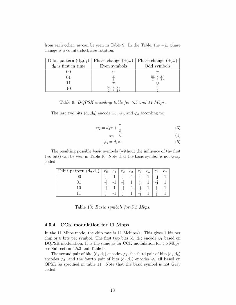
from each other, as can be seen in Table 9. In the Table, the +jω phasechange is a counterclockwise rotation.
Dibit pattern (d0,d1) Phase change (+jω) Phase change (+jω)d0 is first in time Even symbols Odd symbols
00 0 π01 π
23π2 (-π
2 )11 π 010 3π
2 (-π2 ) π
2
Table 9: DQPSK encoding table for 5.5 and 11 Mbps.
The last two bits (d2,d3) encode ϕ2, ϕ3, and ϕ4 according to:
ϕ2 = d2π +π2
(3)
ϕ3 = 0 (4)
ϕ4 = d3π. (5)
The resulting possible basic symbols (without the influence of the firsttwo bits) can be seen in Table 10. Note that the basic symbol is not Graycoded.
Dibit pattern (d2,d3) c0 c1 c2 c3 c4 c5 c6 c7
00 j 1 j -1 j 1 -j 101 -j -1 -j 1 j 1 -j 110 -j 1 -j -1 -j 1 j 111 j -1 j 1 -j 1 j 1
Table 10: Basic symbols for 5.5 Mbps.
4.5.4 CCK modulation for 11 Mbps
In the 11 Mbps mode, the chip rate is 11 Mchips/s. This gives 1 bit perchip or 8 bits per symbol. The first two bits (d0,d1) encode ϕ1 based onDQPSK modulation. It is the same as for CCK modulation for 5.5 Mbps,see Subsection 4.5.3 and Table 9.
The second pair of bits (d2,d3) encodes ϕ2, the third pair of bits (d4,d5)encodes ϕ3, and the fourth pair of bits (d6,d7) encodes ϕ4 all based onQPSK as specified in table 11. Note that the basic symbol is not Graycoded.
18

Dibit pattern (di,di+1) Phasedi is first in time
00 001 π
210 π11 3π
2 (-π2 )
Table 11: Basic symbol for 11 Mbps.
-Scrambleddata in
M
BCC1/2 rateencoder
-(y1 y0)
C
QPSKCoverMap
-QPSK Signal
I,Q
Cover
Code
6
S
Cover Sequence
Figure 2: PBCC Modulator scheme. The scrambled data is 1/2 rate BCC encodedand mapped into QPSK symbols with help of a cover code.
4.5.5 PBCC Modulation for 5.5 and 11 Mbps
This optional coding scheme uses a 64-state Binary Convolutional Code(BCC) and a cover sequence. Firstly, the scrambled data is fed through aconvolutional encoder. Secondly, the output of this convolutional encoderis mapped into a signal constellation, either BPSK or QPSK. In this stagea psuedo-random cover sequence is also added, and the output from theconvolutional encoder and the cover code determinds together to whichsymbol the scrambled data is to be mapped into.
The transfer function matrix of the 64-state BCC is:
G = [D6 + D4 + D3 + D + 1, D6 + D5 + D4 + D3 + D2 + 1]. (6)
The convolutional encoder should start at all-zero-state and also end inall-zero-state, the last in order to keep the reliability throughout the trans-mission. To achieve all-zero-state at the end of a frame, one octet of allzeros should be appended after the last bit of the frame prior to trans-mission. This octet shall then be discarded in each received frame. Inputto the BCC is the scrambled data and then a cover code is applied whichmaps the code to the appropiate symbol, as can be seen in Figure 2.
In Figure 3 the encoder block diagram is shown. The output from thisbinary convolutional coder is mapped to a signal constellation using either
19

input
x- z−1 - z−1 - z−1 - z−1 - z−1 - z−1`
?
`?
`?
`?
`?
`6` 6 6 6
-����+ -����
+ -����+ -����
+ -����+ -
y1
outputs
-����+ -����
+ -����+ -����
+ -y0
Figure 3: The binary convolutional encoder.
the 5.5 Mbps (BPSK) or the 11 Mbps (QPSK) rate. In the 5.5 Mbps modethe output pair of the BCC is taken serially (y0 first) to produce two BPSKsymbols. In the 11 Mbps mode the output pair of the BCC produces oneQPSK symbol. This gives a throghput of 1/2 bit per symbol in the BPSKmode, and 1 bit per symbol in the QPSK mode.
The last chip of the Preamble and Header (i.e. the CRC) determinesthe phase of the first chip of the PSDU, where (y1 y0)=(0 0) indicatesthe same phase and the other three combinations should be defined withrespect to this reference phase as can be viewed in Figure 4.
The output of the BCC is to be mapped to either BPSK or QPSK withhelp of a psuedo-random cover sequence. This cover sequence output is ei-ther s=0 or s=1 and all mapping alternatives are shown in Figure 4. Notethat this is an absolute phase table, not differetial as in CCK. The coversequence is generated from a 16-bit seed sequence (0011001110001011),where the leftmost bit is first in time. This seed sequence is used to gener-ate a 256 bits long cover sequence that is used in the mapping of the PSKsymbol. The current binary value, in time, of this cover sequence is takenas s in Figure 4. The 256 bits long cover sequence is generated as follows:The first 16 bits is the seed, the second 16 bits is the seed cyclically rotatedthree bits to the left (time direction), the third 16 bits is the seed cyclicallyrotated six bits to the left, and so on 16 times. This yields a 256 bits longcover sequence. If the PPDU contains more than 256 data bits the coversequence is simply repeated the appropriate number of times. An exam-ple of the cover sequence with (0,0,1,1,0,0,1,1,1,0,0,0,1,0,1,1)=(c0, ..., c15)follows below:
c0, c1, c2, c3, c4, c5, c6, c7, c8, c9, c10, c11, c12, c13, c14, c15
c3, c4, c5, c6, c7, c8, c9, c10, c11, c12, c13, c14, c15, c0, c1, c2
c6, c7, c8, c9, c10, c11, c12, c13, c14, c15, c0, c1, c2, c3, c4, c5
...
c13, c14, c15, c0, c1, c2, c3, c4, c5, c6, c7, c8, c9, c10, c11, c12
20

BPSK mode1/2 bit/symbol
S=0 b 0
b1
S=1b0
b 1
QPSK mode1 bit/symbol
(y1 y0)
S=0
b 10
b 00
b11
b01
S=1
b 11
b 10
b01
b00
Figure 4: The Cover Code mapping scheme. The Cover Codes present value, S,determines to which signal constellation to map the data into.
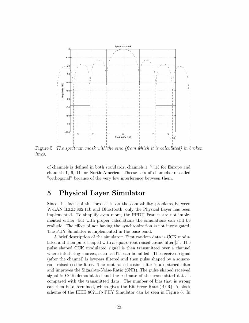
4.6 Spectrum maskThe IEEE standard specifies a Spectrum Mask that the spectrum of thetransmitted signal must not exceed. The levels specified are 0 dB from themain lobe of a sinc, -30 dB from the first lobe of a sinc, and -50 dB fromthe second lobe of a sinc. This gives the levels 0 dB within [-11 11]MHz,-43.3 dB within [-22 -11] and [11 22]MHz, and -67.8 dB within [-∞ -33]and [33 ∞]MHz. In Figure 5 this spectrum mask can be seen as the solidlines.
4.7 SensitivityThe sensitivity of a W-LAN within the IEEE 802.11b standard should beat least -76 dBm with a Frame Error Rate (FER) of 8 ∗ 10−2. The frameshould have 1024 octets in the PSDU field and the modulation should be11 Mbps CCK.
4.8 Channel placementThe IEEE 802.11b standard specifies where in the ISM band the differentchannels are allocated. There are different allocations for Europe andNorth America. Europe has 13 operating chanels and North America has11 operating channels. Channel number ”1” is allocated at 2412 MHz(center frequency) and there are 5 MHz spacing between every channel inboth standards meaning that the European allocation stops at 2472 MHzand the American allocation stops at 2462 MHz. Since the channels are 22MHz wide they overlap each other and for that reason an ”orthogonal” set
21
−3 −2 −1 0 1 2 3
x 107
−100
−90
−80
−70
−60
−50
−40
−30
−20
−10
0Spectrum mask
Frequency [Hz]
Am
plitu
de [d
B]
Figure 5: The spectrum mask with the sinc (from which it is calculated) in brokenlines.
of channels is defined in both standards, channels 1, 7, 13 for Europe andchannels 1, 6, 11 for North America. Theese sets of channels are called”orthogonal” because of the very low interference between them.
5 Physical Layer SimulatorSince the focus of this project is on the compability problems betweenW-LAN IEEE 802.11b and BlueTooth, only the Physical Layer has beenimplemented. To simplify even more, the PPDU Frames are not imple-mented either, but with proper calculations the simulations can still berealistic. The effect of not having the synchronization is not investigated.The PHY Simulator is implemented in the base band.
A brief description of the simulator: First random data is CCK modu-lated and then pulse shaped with a square-root raised cosine filter [5]. Thepulse shaped CCK modulated signal is then transmitted over a channelwhere interfering sources, such as BT, can be added. The received signal(after the channel) is lowpass filtered and then pulse shaped by a square-root raised cosine filter. The root raised cosine filter is a matched filterand improves the Signal-to-Noise-Ratio (SNR). The pulse shaped receivedsignal is CCK demodulated and the estimate of the transmitted data iscompared with the transmitted data. The number of bits that is wrongcan then be determined, which gives the Bit Error Rate (BER). A blockscheme of the IEEE 802.11b PHY Simulator can be seen in Figure 6. In
22

-datain
CCKencode
- RRCFilter
6
Channeladding noise andother interference
- LPFilter
- RRCFilter
- CCKdecode
-dataout
Figure 6: IEEE 802.11b Pyhsical Layer Simulator block scheme.
the following sections the different building blocks of this PHY Simulatorare described in more detail.
5.1 ModulationOnly the High Rate mode with CCK modulation (5.5 and 11 Mbps) wasimplemented. The CCK code is created according to the standard spec-ified above (Subsections 4.5.3, 4.5.4). In the demodulation of the CCKcodewords the signal is sampled and the values from a whole codewordare compared with a table containing all possible codewords. The mostlikely received codeword is chosen with respect to minimum distance. Forevery possible codeword in the table, the corresponding databits are readoff from another table.
The optional PBCC modulation was implemented but due to extremelylong simulation times, no simulations with accuracy was performed. Thelong simulation times comes from that PBCC uses a 64-state binary convo-lutional code. The PBCC modulation is fast but the PBCC demodulationis very slow.
5.2 Pulse shapingTo achieve a transmitted signal that conforms with the specified spectrummask, the signal must be pulse shaped. To solve this problem a square-rootraised cosine filter, in both the transmitter and receiver, was implemented.The filters have a roll-off factor of 0.35 and a window size of [-4, 4] symbolintervals. The impulse response of the filter is shown in Figure 7.
5.3 Sample pointThe pulseshaping filters and the lowpass filter all introduces delays to thetransmitted signal and to be able to demodulate the received signal sucess-fully the correct sample point must be determined. In order to solve this
23

0 10 20 30 40 50 60 70−0.1
−0.05
0
0.05
0.1
0.15
0.2
0.25
0.3
0.35
0.4Pulseshaped symbol
Figure 7: The square-root raised cosine pulseshaped symbol in the time domain.
problem the eyepattern was plotted and the sample point could be deter-mined. As can be seen in Figure 8 the sample point is a little bit off theoptimal value, but this was the closest sample since the delay introducedby the filters is not an integer multiple of the sampling interval. The sam-ple point is fairly close to the optimal value so this should however notaffect the performance to much.
5.4 ChannelThe channel simulates the air interface where different interfering sourcescan be added to the transmitted signal. Interfering sources can be Blue-Tooth transmitters or other IEEE 802.11b sources. AWGN can also beadded to the transmitted signal. The channel is an ideal, linear channelwithout multipath. The amplitudes and the locations in the spectrum ofthe interfering source can be altered in order to achieve relevant simula-tions.
5.5 Lowpass filteringIn order to filter out the interesting part of the received spectra a lowpassfilter was designed in Matlab. The filter represents the analogue selectivebandpass filter (22 MHz) of the receiver. It is a fourth order Butterworth
24

0.5 0.6 0.7 0.8 0.9 1 1.1 1.2 1.3 1.4 1.5
−1.5
−1
−0.5
0
0.5
1
1.5
DPoint
time (second)
ampl
itude
Eye−Pattern Diagram
Figure 8: Eyepattern and sample point of the lowpass filtered pulseshaped receivedsymbol.
filter with a 3 dB cut-off frequency at 11 MHz and the filter coefficientsare as follows:
numerator = [0.0102, 0.0408, 0.0613, 0.0408, 0.0102],
denominator = [1.0000,−1.9684, 1.7359,−0.7245, 0.1204].
6 Simulations and resultsThis chapter presents the simulations and the corresponding results. Dueto the complicated calculations, the computer ran out of memory if thenumber of transmitted bits exceeded a certin threshold. In almost all sim-ulations the threshold was 100 kbit but this still gives a satisfying accuracy.The sampling frequency was 88 MHz in all simulations.
6.1 Spectrum of the implemented transmitterIn order to test if the pulseshaping filter fulfills the specification, the spec-trum of the pulseshaped signal was calculated 100 times and then themean spectrum was plotted together with the specified spectrum mask,see Figure 9. We can see that the specification is not completely fulfilled.The specification was hard to fulfill with resonable parameters in the pulseshaping filter but the parameters in Section 5.2 are a good choice withrespect to both simulation times and the IEEE 802.11b spectrum mask.
25

−3 −2 −1 0 1 2 3
x 107
−100
−90
−80
−70
−60
−50
−40
−30
−20
−10
0Spectrum mask
Frequency [Hz]
Am
plitu
de [d
B]
Figure 9: The spectrum of the pulseshaped signal and the spectrum mask.
In Figure 10 the spectrum from both the pulseshaped and the nonpulseshaped signal can be viewed. As can be seen the pulseshaped signalhas much more efficient spectrum, i.e. there is almost no energy where itis not needed.
6.2 Sensitivity of the implemented receiverSensitivity is a measure of how good the receiver is. AWGN is used toinvestigate which signal strengt the received signal must have when the re-ceiver detects a defined FER or BER. To be able to measure the sensitivitywithout constructing PPDU frames, the FER was converted to BER ac-cording to the calculations below. The probability that a frame is detectedcorrectly is:
PFrameCorrect = (Pc)1 ∗ (Pc)2 ∗ ... ∗ (Pc)N = (Pc)N , (7)
where Pc is the probability that a bit is correct and N is the total numberof transmitted bits.
The probabilty that a bit is wrong is:
Pb = 1− Pc ↔ Pc = 1− Pb, (8)
where Pb is the probability that a bit is wrong.
26

−4 −3 −2 −1 0 1 2 3 4
x 107
−100
−80
−60
−40
−20
0Spectrum of received non pulseshaped CCK code
Frequency [Hz]
Am
plitu
de [d
B]
−4 −3 −2 −1 0 1 2 3 4
x 107
−100
−80
−60
−40
−20
0Spectrum of received pulseshaped CCK code
Frequency [Hz]
Am
plitu
de [d
B]
Figure 10: The spectrum of the non pulseshaped and pulseshaped signal.
Equation (7) and (8) gives the final equation:
Pb = 1− (1− PFrameWrong)1N , (9)
where Pb is expressed in terms of the probability of frame errors.Accordig to the specification 1024 octets in the PSDU field should be
used to measure the sensitivity. 1024 octets in the PSDU field gives 8192bits to transmit. The bits in the Preamble and Header are protected harder(see Subsection 4.2.6 and Section 4.4) and these fields together consists ofonly 192 bits. Therefore those bits has been removed from the calculation.With the specified FER (see Section 4.7) and with 8192 bits, the BER is:
Pb = 1− (1− PFrameWrong)1N = 1− (1− 8 ∗ 10−2)
18192 = 1.0178 ∗ 10−5,(10)
which is rounded to 1.0∗10−5 for safety and due to that the Preamble andHeader bits was ignored.
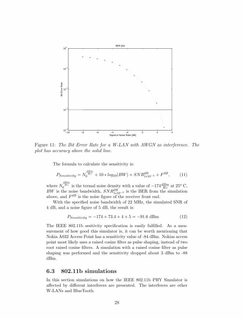
A simulation with the IEEE 802.11b simulator and AWGN were con-ducted in Matlab in order to control whether the sensitivity criteria wasfulfilled. Long computation times limited the simulation length to 100kbit. The rule of thumb ”10x bits gives an accuracy of 10−(x−2)” gives,with 100kb, an accuracy of 10−3. In Figure 11 the result can be viewedwith accuracy above the horisontal line. The simulation indicates that aSNR of more than 4 dB is required to give a FER of less than 8 ∗ 10−2
for a BER of less than 1.0 ∗ 10−5. It is worth mentioning that the lowpassfilter affect the AWGN created in Matlab, and the calculations to obtainthe correct SNR can be found in Appendix A.
27
−10 −8 −6 −4 −2 0 2 410
−4
10−3
10−2
10−1
100
BER plot
Signal to Noise Ratio [dB]
Bit
Err
or R
ate
Figure 11: The Bit Error Rate for a W-LAN with AWGN as interference. Theplot has accuracy above the solid line.
The formula to calculate the sensitivity is:
PSensitivity = NdBmHz
0 + 10 ∗ log10(BW ) + SNRdB1∗10−5 + F dB, (11)
where NdBmHz
0 is the termal noise density with a value of −174dBmHz at 25o C,
BW is the noise bandwidth, SNRdB1∗10−5 is the BER from the simulation
above, and F dB is the noise figure of the receiver front end.With the specified noise bandwidth of 22 MHz, the simulated SNR of
4 dB, and a noise figure of 5 dB, the result is:
PSensitivity = −174 + 73.4 + 4 + 5 = −91.6 dBm (12)
The IEEE 802.11b sesitivity specification is easily fulfilled. As a mea-surement of how good this simulator is, it can be worth mentioning thatNokia A032 Access Point has a sensitivity value of -84 dBm. Nokias accesspoint most likely uses a raised cosine filter as pulse shaping, instead of tworoot raised cosine filters. A simulation with a raised cosine filter as pulseshaping was performed and the sensitivity dropped about 3 dBm to -88dBm.
6.3 802.11b simulationsIn this section simulations on how the IEEE 802.11b PHY Simulator isaffected by different interferers are presented. The interferers are otherW-LANs and BlueTooth.
28

6.3.1 802.11b disturbed by another 802.11b
The interference between different W-LANs has been simulated in Matlabwith the interfering W-LAN at the same channel and at four other differentchannels (each 5 MHz apart) that partly shares the same spectrum. Twosimulations between the defined ”orthogonal” channels in the specification,i.e. channel 6 (North America) and channel 7 (Europe). To be able tocompare the simulations and as a measure of how disturbed the receivergets, the Carrier-to-Interference ratio (C/I) is read off at the same BER.The choosen value of the bit error rate, to read off the C/I ratio, is 1∗10−5.Since 100 kbits were transmitted full confidience is not attained at thislevel, so the C/I value is approximate. The reason this level of the BER ischosen is that the sensitivity of a IEEE 802.11b W-LAN is defined at thislevel, and hence has this level an acceptable level of errors. Of course theinterfering source and the original source had different sets of random bitstransmitted. The result of these simulations can be seen in Table 12 andthe C/I plot between channel 1 and 3 can be seen in Figure 12.
If there is no AWGN added to the signal, both W-LANs operates at thesame channel, and both W-LANs is synchronus, the one which is strongerin amplitude is demodulated without errors. This is correct due to thesignal constellations decision rules detects the stronger one. Since thatoccurs, the interfering W-LAN were set to a different time to start at.In all these simulations the interfering W-LAN synchronization (samplepoint) was set to start two samples before the W-LAN to be interfered,100 kbits was transfered, and no AWGN was used.
Distance between channels (MHz) 0 5 10 15 20 25 30C/I in dB
at BER=1 ∗ 10−5 5 3 -4 -40 -54 -60 -63
Table 12: C/I ratio between different W-LAN’s allocated at different channels. Itis 5 MHz between the center frequency of every channel.
6.3.2 802.11b disturbed by BlueTooth
To measure BlueTooth’s interfering effect on the IEEE 802.11b W-LAN,simulations in Matlab were conducted. Two simulations of a frequencyhopping BT inteferer were made, one with 5.5 Mbps and one with 11Mbps in order to measure how the bitrate affects the W-LANs toleranceto interferance. Also in these simulations 100 kbit were transmitted. TheBT linksimulator was slightly modified, a frequency hopping scheme wereadded in order to ”spend” the appropriate time within the bandwidth ofthe W-LAN. An IEEE 802.11b W-LAN uses 22 MHz of the ISM bands83.5 MHz, this is about 26% of the ISM band. Therefore the BT hopping
29

−10 −9 −8 −7 −6 −5 −410
−5
10−4
10−3
10−2
10−1
100
C/I plot
Carrier to Interferer Ratio [dB]
Bit
Err
or R
ate
Figure 12: The Bit Error Rate for a W-LAN interfered by another W-LAN.Channel 1 vs. channel 3, i.e. 10 MHz apart.
scheme was constructed so it spent about 26% of its time in the bandwidthof the W-LAN to be interfered. A plot of these three simulations can beseen in Figure 13.
6.4 BlueTooth simulationIn this section a simulation of how the BlueTooth PHY simulator is affectedby the IEEE 802.11b PHY simulator is presented.
6.4.1 BlueTooth disturbed by 802.11b
To measure the IEEE 802.11b W-LAN’s interfering effect on BlueTooth,simulations in Matlab were conducted. In order to keep the sampling fre-quency of the simulation as small as possible the BT signal only hopswithin the bandwidth of the W-LAN. To simulate hops outside the band-width of the W-LAN, the W-LAN’s signal is set to zero about 75% of thetime. This way the sampling frequency can be kept low and the result isrealistic. In this simulation 1 Mbits were transmitted and that gives, withthe rule of tumb, an accuracy to 10−4. The interfering W-LAN was run inthe 11 Mbps mode. The result of this simulation can be seen in Figure 14.
30

−4 −3 −2 −1 0 1 2 310
−4
10−3
10−2
10−1
W−LAN interfered by BlueTooth
Carrier to Interferer Ratio [dB]
Bit
Err
or R
ate
Figure 13: Carrier-to-Interferer ratio plot. Two cases: 1) 5.5 Mbps W-LAN vs.Frequency Hopping BlueTooth (dots) 2) 11 Mbps W-LAN vs. Frequency HoppingBlueTooth (crosses).
−2 −1 0 1 2 3 4 5 610
−4
10−3
10−2
10−1
C/I [dB]
Bit
Err
or R
ate
BlueTooth with a W−LAN as an interferer
Figure 14: The Bit Error Rate for BlueTooth interfered by a W-LAN.
31

−2 −1 0 1 2 3 4 5 610
−4
10−3
10−2
10−1
W−LAN interfered by BlueTooth and vice versa
Carrier to Interferer Ratio [dB]
Bit
Err
or R
ate
Figure 15: Carrier-to-Interferer ratio plot. Two cases: 1) BlueTooth interferedby a 11 Mbps W-LAN transmitter (dotted line with crosses) 2) 11 Mbps W-LANinterfered by a BlueTooth transmitter (solid line with circles).
6.5 Combining resultsTo be able to compare the simulation of a 11 Mbps W-LAN interfered by aBlueTooth transmitter and the simulation of a BlueTooth system interferedby a 11 Mbps W-LAN, their respective results are plotted in Figure 15.
7 ConclusionsIn the following sections the conditions for the simulations, a discussion ofthe obtained results, and ideas to future work are presented.
7.1 Conditions for the simulationsThe developed simulator is a simplified version of the IEEE 802.11b stan-dard. Firstly, only the Physical layer is simulated, and secondly, only thedata is transfered, i.e. the preamble and header are not implemented. How-ever, this is still very close to reality. The preamble and header is protectedharder by lower bitrate (better Processing Gain), scrambled data, and byredundance check. The data to be transmitted has no protection, i.e. nocoding, within the IEEE 802.11b standard. The protection of the databitsdepends on higher layers, for example if TCP/IP is used. The effect ofnot having the synchronisation is not investigated. The channel has beena non fading linear channel to which different interferers have been added.
32

To be able to compare the different simulations, the C/I or SNR valueis read off at the same BER value. The choosen BER value is 1 ∗ 10−5
since the sensitivity of a IEEE 802.11b W-LAN is defined at this level, andhence has this level an acceptable level of errors. Since the simulationswere made with 100 kbit, full confidence is not attained at this BER sothe SNR or C/I value is approximate. The simulation investigating howmuch BlueTooth is interfered by a W-LAN is read off at a BER = 1∗ 10−3
since the sensitivity for BlueTooth is defined at that level.
7.2 Discussion of the obtained resultsIn this section a discussion of the obtained results are presented:
• W-LAN in an AWGN enviromentThe sensitivity specification of this W-LAN simulator is measured inpresence of AWGN and the specification was easily fulfilled. WithAWGN as disturbance the approximate SNR value at a BER = 10−5
is 5 dB.
• W-LAN disturbed by another W-LANThe disturbing effect of an interfering W-LAN decreases drastically asthe overlapping between the channels is decreased. When the centerfrequencies of the channels are 10 MHz apart the C/I ratio is -4 dBand with 15 MHz spacing the C/I ratio is -40 dB, both at BER =1∗10−5. The significant drop at this point is expected because of thesingle sided pulse shaped signal is smaller than 7.5 MHz and hencethe interference decreaces drastically. The IEEE standard defines 25MHz spacing between center frequncies in North America to attain”ortogonality” and it seemes as a good choice, the C/I value in thiscase is -60 dB. The IEEE standard defines the European spacingbetween channels to be 30 MHz, and in this case the C/I value is-63 dB. When the W-LANs center frequncies are over 20 MHz apartthe C/I ratio is smaller than -54 dB at BER = 1 ∗ 10−5. To beable to compare the interference of a W-LAN with the interferenceof BlueTooth and AWGN the simulation with W-LANs at the samechannel is used. With both W-LANs at the same channel the C/Iratio at BER = 1 ∗ 10−5 is 5 dB.
• W-LAN disturbed by BlueToothIn these simulations frequency hopping BlueTooth was used as inter-ferer. The frequency hopping scheme was constructed so the Blue-Tooth interferer spent about 26% of its time in the W-LAN’s band-width. A narrow band interferer (as BT is) affects the W-LAN in11 Mbps mode more. This is because the processing gain is smallerin this case, which makes it more sensitive to disturbance. The pro-cessing gain is the band width divided with the speed of the data,which gives in the 5.5 Mbps case a processing gain of 2, and in the
33

11 Mbpsk case a processing gain of 1. With the 11 Mbps W-LANand the frequency hopping BlueTooth as interferer the C/I ratio ata BER = 1 ∗ 10−5 is 4 dB and with the 5.5 Mbps W-LAN the C/Iratio is 1 dB.
• BlueTooth disturbed by W-LANThe BlueTooth simulation had a 11 Mbps W-LAN as interferer andthe BlueTooth was run without Forward Error Correction. At a BER= 1 ∗ 10−3 the C/I ratio is 4 dB (the approximate C/I value at BER= 1 ∗ 10−5 is 8 dB).
For W-LAN it is the worst case to have another W-LAN at the same chan-nel as an interferer but it is only small differencies to the other interferingsources and this is resonable because of the similarities in modulation etc.The W-LAN handles the BlueTooth interference better in the 5.5 Mbpsmode than in the 11 Mbps mode. With the 11 Mbps mode W-LAN inter-fered by BlueTooth the BER is very similar to the same 11 Mbps modeW-LAN disturbed by AWGN. Both the W-LAN system and the BlueToothsystem seems to require the same C/I ratio (4 dB) to obtain their sensitiv-ity levels (1 ∗ 10−5 respectively 1 ∗ 10−3). The BlueTooth system handlesthe interference from the W-LAN better when the C/I ratio is equal, butthe 11 Mbps W-LAN’s BER decreases faster, as the C/I ratio increases,than the BlueTooth systems BER. At C/I = 2 dB the W-LAN has equalBER as the BlueTooth system, and for C/I ratios bigger than 2 dB theW-LAN has smaller BER than the BlueTooth system.
7.3 Limitations and future workIn this section the limitations and future work of this project are presented.
• Traffic ScenarioThe simulations in this report have constant transmitting W-LANand BlueTooth transmitters, this is however not likely to be the casein a real life scenario. It is more likely that the transmissions arebursty depending on the data traffic at the time. When this occursthe performance of the system increases to the limit the noise gives.Therefore, the average performance of coexisting systems that sendstheir transmissions in bursts should be better than the perfomanceof coexisting systems that sends their transmissions constantly.
• Future workIn order to examine the performance degradation (due to interferers)more accurate the whole frame with preamble, header, and synchro-nization should be buildt up. It would also be interesting to look athow a fading channel and antenna diversity affects the performance.It would be good to use another programming language than Mat-lab because of slow calculations. Perhaps C-programming or to writeC-mex code in Matlab would suit this purpose better.
34
To be able to investigate the coexistens between W-LAN’s and BlueToothdevices a full traffic scenario must be considered. However, the obtainedresults indicates that coexistance is possible. The interference is also de-pending on the environment, range to basestations, traffic load, and thepower transmitted.
35

A AppendixThe AWGN created in Matlab is affected by the lowpass filtering andtherefor the correct SNR value must be calculated in the simulations withAWGN. This is performed by calculating the signal effect of a received sig-nal with AWGN and the signal effect of a received signal without AWGN,both after the lowpass filter, and with these signal effects calculate theeffect the lowpass filter has on the AWGN. This is possible since the noiseand the signal are independant and the calculation is as follows:
σ2n = σ2
s − σ2s+n, (13)
where σ2n is the signal effect of the noise (AWGN), σ2
s is the signal effectof the received signal without AWGN, and σ2
s+n is the signal effect of thereceived signal with AWGN.
After the calculation of the noise effect, the SNR is easily determinedas follows:
SNRdB = 10 ∗ log10(σ2
s
σ2n). (14)
The simulations gives that the SNR grows about 6 dB after lowpass filter-ing.
The signal effect of the noise can also be calculated theoretically asfollows:
σ2n−prior = No ∗BWn (15)
σ2n−after = No ∗BWLP , (16)
where BWn is the bandwidth of the original noise, and where BWLP is thebandwidth of the lowpass filtered noise. No is the noise spectral densityand is the same in both equations.
The bandwidth of the noise depends on the sampling frequency. Hence,BWn = Fs
2 and the filtred noise has the same bandwidth as the filter,BWLP = Fc=Cut-off frequency. In the simulations the sampling frequencyis 88 MHz and the cut-off frequency of the lowpass filter is 11 MHz. Thisgives that the relation between these equations is:
BWn
BWLP=
Fs2Fc
=4411
= 4. (17)
This gives the teoretical change after lowpass filtering:
10 ∗ log10(BWn
BWLP) = 10 ∗ log10(4) = 6.02 dB. (18)
The simulations gives a SNR value about 6 dB larger after lowpassfiltering and theoretically it is 6.02 dB larger after lowpass filtering.
36

References[1] R.L. Peterson, R.E. Ziemer, D.E. Borth, 1995, Introduction
to spread spectrum communicationsPrentice-Hall. ISBN 0-02-431623-7
[2] AU-system, January 2000 BlueTooth White Paper 1.1http://www.ausys.se/publications/btwp0007.pdf (01-01-10)
[3] IEEE Std 802.11Information technology-Telecommunications and informa-tion exchange between systems-Local and metropolitan areanetworks-Specific requirements-Part 11: Wireless LANMedium Access Control (MAC) and Physical Layer (PHY)specificationshttp://grouper.ieee.org/groups/802/11/ (01-01-10)
[4] IEEE Std 802.11b/D7.0(Draft Supplement to IEEE Std 802.11 1999 Edition)DRAFT Supplement to STANDARD [for] InformationTechnology-Telecommunications and information exchangebetween systems-Local and metropolitan area networks-Specific requirements-Part 11: Wireless LAN Medium Ac-cess Control (MAC) and Physical Layer (PHY) specifica-tions: Higher speed Physical Layer (PHY) extension in the2.4 GHz band.http://grouper.ieee.org/groups/802/11/ (01-01-10)
[5] John G. Proakis, Digital communicationsMcGraw-Hills. ISBN 0-07-051726-6
[6] Wireless-Nets, January 2000 Interference Potential BetweenBluetooth and IEEE 802.11, by Jim Geierhttp://www.wireless-nets.com/whitepaper interference.htm(01-01-10)
[7] Several W-LAN and W-PAN coexistance articles, at IEEE802.15 WPAN Task Group 2 (TG2)http://grouper.ieee.org/groups/802/15/pub/TG2.html(01-01-10)
[8] ETSI HIPERLAN/2 standardhttp://www.etsi.org/technicalactiv/hiperlan2.htm(01-01-22)
37