piling technical guidance steel sheet · pdf filepiling direction self-moving procedure saddle...
TRANSCRIPT

STEE
L SH
EET
PILE
S
RETA
ININ
G W
ALL
SV
INYL
PIL
ING
CORN
ER P
ILES
COFF
ERDA
MS
PERM
AN
ENT
BASE
MEN
TS
STEE
L BE
ARI
NG
FOU
NDA
TIO
NS
VIB
RATO
RY P
ILIN
G
TEM
PORA
RY S
HEE
T PI
LIN
GM
ARI
NE
WO
RKS
COM
POSI
TE P
ILES
GRO
UN
D A
NCH
ORS
VIB
RATI
ON
FRE
E PI
LIN
G
JET
FILT
ER W
EEP
HO
LES
STEE
L SH
EET
PILE
S
RETA
ININ
G W
ALL
SV
INYL
PIL
ING
CORN
ER P
ILES
COFF
ERDA
MS
PERM
AN
ENT
BASE
MEN
TS
STEE
L BE
ARI
NG
FOU
NDA
TIO
NS
VIB
RATO
RY P
ILIN
G
TEM
PORA
RY S
HEE
T PI
LIN
GM
ARI
NE
WO
RKS
COM
POSI
TE P
ILES
GRO
UN
D A
NCH
ORS
VIB
RATI
ON
FRE
E PI
LIN
G
JET
FILT
ER W
EEP
HO
LES
STEE
L SH
EET
PILE
S
RETA
ININ
G W
ALL
SV
INYL
PIL
ING
CORN
ER P
ILES
COFF
ERDA
MS
PERM
AN
ENT
BASE
MEN
TS
STEE
L BE
ARI
NG
FOU
NDA
TIO
NS
VIB
RATO
RY P
ILIN
G
TEM
PORA
RY S
HEE
T PI
LIN
GM
ARI
NE
WO
RKS
COM
POSI
TE P
ILES
GRO
UN
D A
NCH
ORS
VIB
RATI
ON
FRE
E PI
LIN
G
JET
FILT
ER W
EEP
HO
LES
STEE
L SH
EET
PILE
S
RETA
ININ
G W
ALL
SV
INYL
PIL
ING
CORN
ER P
ILES
COFF
ERDA
MS
PERM
AN
ENT
BASE
MEN
TS
STEE
L BE
ARI
NG
FOU
NDA
TIO
NS
VIB
RATO
RY P
ILIN
G
TEM
PORA
RY S
HEE
T PI
LIN
GM
ARI
NE
WO
RKS
COM
POSI
TE P
ILES
GRO
UN
D A
NCH
ORS
VIB
RATI
ON
FRE
E PI
LIN
G
JET
FILT
ER W
EEP
HO
LES
STEE
L SH
EET
PILE
S
RETA
ININ
G W
ALL
SV
INYL
PIL
ING
CORN
ER P
ILES
COFF
ERDA
MS
PERM
AN
ENT
BASE
MEN
TS
STEE
L BE
ARI
NG
FOU
NDA
TIO
NS
VIB
RATO
RY P
ILIN
G
TEM
PORA
RY S
HEE
T PI
LIN
GM
ARI
NE
WO
RKS
COM
POSI
TE P
ILES
GRO
UN
D A
NCH
ORS
VIB
RATI
ON
FRE
E PI
LIN
G
JET
FILT
ER W
EEP
HO
LES
SILENT & VIBRATION FREE
PILING TECHNICAL GUIDANCE

1. Safetyn No machine instability.n Fully hydraulic clamping system.n Remote control operation.n Eliminates ‘working at height’.
2. Environmentaln Vibration free.n Noise free.n Minimise influence on surrounding environment.n Minimise temporary works.n Effective for pile extraction allowing re-use.
3. Qualityn Accurate pile alignment and installation tolerances.n Pre-formed quality controlled steel pile product.n Various aesthetical finishes available.
4. Programmen Self-walking system reduces construction programme.n No limitation on working hours.n ‘One-Stop’ construction method.
5. Costn Reduced temporary works (temporary platforms, earth works, road diversions).n Minimal labour requirement.n Maximise off-site design and fabrication.
2
“As one of the UK’s leading driven steel piling contractors, Sheet Piling (UK) Ltd has built its reputation on solid foundations.”
THE FIVE PRINCIPAL BENEFITS OF PILE PRESS-IN TECHNOLOGY
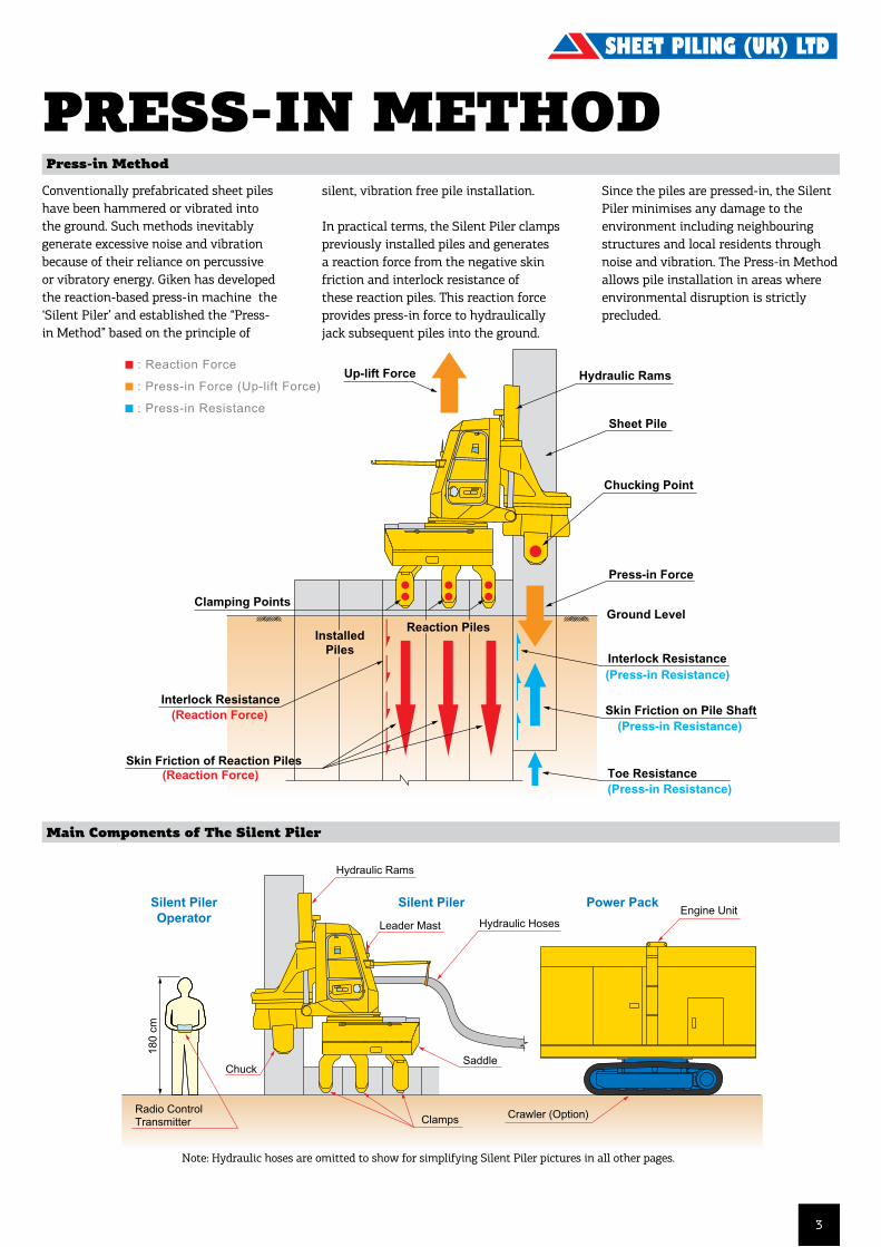
Press-in Method
Conventionally prefabricated sheet piles have been hammered or vibrated into the ground. Such methods inevitably generate excessive noise and vibration because of their reliance on percussive or vibratory energy. Giken has developed the reaction-based press-in machine the ‘Silent Piler’ and established the “Press-in Method” based on the principle of
PRESS-IN METHOD
Giken advocates and promotes the "Construction Revolution" to establish a new
standard which surpasses the convention of the current construction industry. The
fundamental concept of our Construction Revolution is the environmentally friendly
"Press-in Method" that hydraulically installs piles silently and without vibration by
static load making use of the "Reaction Force" principle.
Conventionally prefabricated piles have been pounded or vibrated into the ground. Such methods
inevitably generate excessive noise and vibration because of their reliance on percussive or
vibratory energy. Giken has developed the reaction-based press-in machine the "Silent Piler"
and established the "Press-in Method" based on the principle of non-pollutive pile installation.
In practical terms, the Silent Piler grasps previously installed piles and derives reaction force from
the negative skin friction and interlock resistance of these reaction piles. This reaction force
provides press-in force to hydraulically jack subsequent piles into the ground. Since the piles are
pressed-in, the Silent Piler does not cause any damage to the environment including neighboring
structures and local residents through noise and vibration. The Press-in Method allows pile
installation in areas where environmental disruption is strictly precluded.
Remarks: Hydraulic hoses are omitted to show for simplifying Silent Piler pictures in all other pages.
ClampsRadio Control Transmitter
Engine Unit
Chuck
Silent PilerOperator
Silent Piler Power Pack
180
cm
Saddle
Crawler (Option)
Hydraulic Hoses
Hydraulic Rams
Leader Mast
Specifications are available atGiken's corporate homepage.
downloaded from Giken's corporate home page athttp://www.giken-smp.com/
Copyright © Giken Seisakusho Co., Ltd. All Rights Reserved. Ver. 2.1 / 15 Feb. 2001
Chucking Point
Ground Level
Skin Friction of Reaction Piles
(Press-in Resistance)
(Press-in Resistance)
Skin Friction on Pile Shaft
Clamping Points
(Reaction Force)
InstalledPiles
(Press-in Resistance)
Interlock Resistance
Toe Resistance
Press-in Force
Sheet Pile
Hydraulic RamsUp-lift Force
(Reaction Force)Interlock Resistance
Reaction Piles
: Reaction Force
: Press-in Force (Up-lift Force)
: Press-in Resistance
silent, vibration free pile installation.
In practical terms, the Silent Piler clamps previously installed piles and generates a reaction force from the negative skin friction and interlock resistance of these reaction piles. This reaction force provides press-in force to hydraulically jack subsequent piles into the ground.
Main Components of The Silent Piler
Note: Hydraulic hoses are omitted to show for simplifying Silent Piler pictures in all other pages.
Since the piles are pressed-in, the Silent Piler minimises any damage to the environment including neighbouring structures and local residents through noise and vibration. The Press-in Method allows pile installation in areas where environmental disruption is strictly precluded.
3
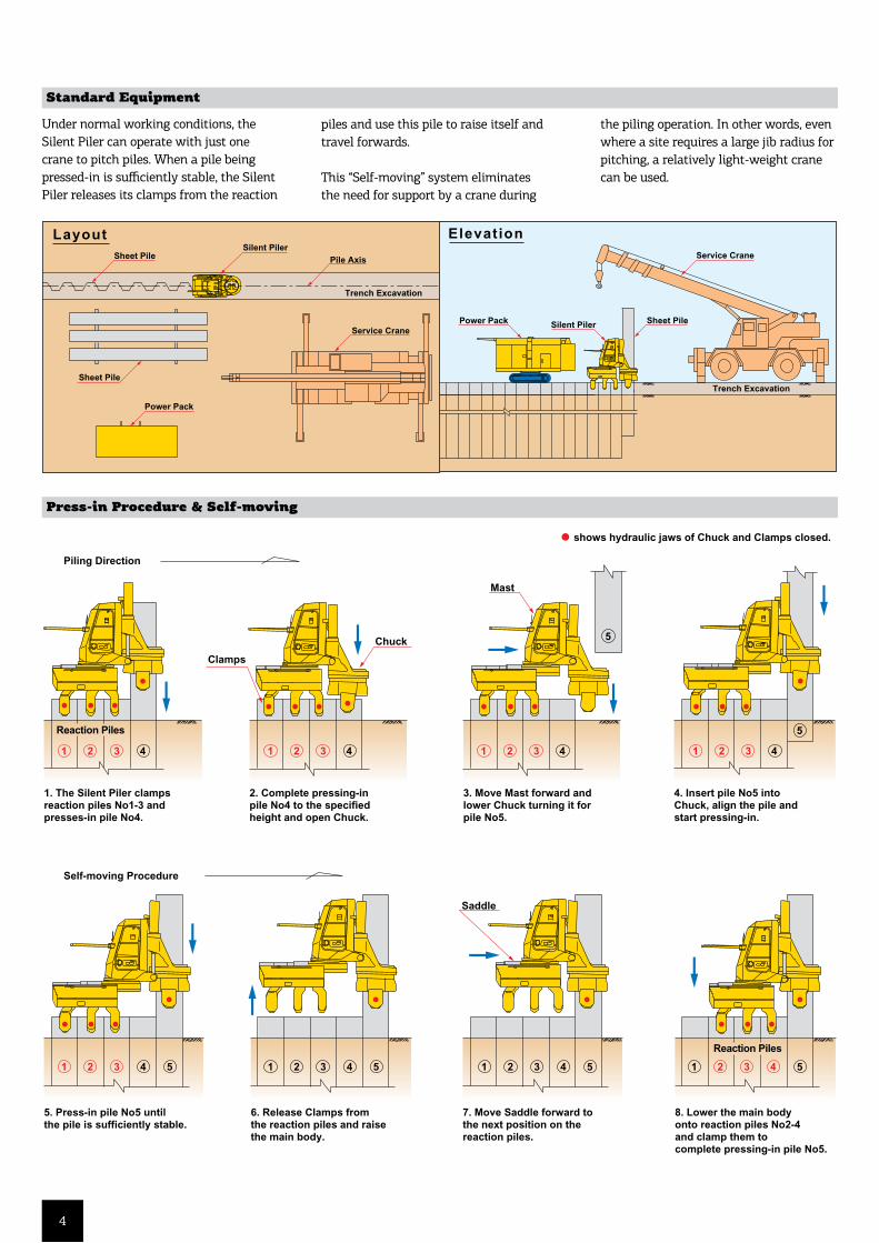
Standard Equipment
Under normal working conditions, the Silent Piler can operate with just one crane to pitch piles. When a pile being pressed-in is sufficiently stable, the Silent Piler releases its clamps from the reaction
piles and use this pile to raise itself and travel forwards.
This “Self-moving” system eliminates the need for support by a crane during
the piling operation. In other words, even where a site requires a large jib radius for pitching, a relatively light-weight crane can be used.
downloaded from Giken's corporate home page athttp://www.giken-smp.com/
Copyright © Giken Seisakusho Co., Ltd. All Rights Reserved. Ver. 2.1 / 15 Feb. 2001
Under normal working conditions, the Silent Piler can operate with just one crane to pitch piles. When a pile being pressed-in is
sufficiently stable, the Silent Piler releases its clamps from the reaction piles and use this pile to raise itself and travel forwards.
This "Self-moving" system eliminates the need for support by a crane during the piling operation. In other words, even where a site
requires a large jib radius for pitching, a relatively light-weight crane can be used.
Power Pack
Sheet PileSilent Piler
Pile Axis
Sheet Pile
Service Crane
Service Crane
Sheet PilePower Pack Silent Piler
Trench Excavation
Trench Excavation
ElevationLayout
shows hydraulic jaws of Chuck and Clamps closed.
Piling Direction
Self-moving Procedure
Saddle
Mast
Chuck
Reaction Piles
8. Lower the main body onto reaction piles No2-4 and clamp them to complete pressing-in pile No5.
7. Move Saddle forward to the next position on the reaction piles.
6. Release Clamps from the reaction piles and raise the main body.
5. Press-in pile No5 until the pile is sufficiently stable.
4. Insert pile No5 into Chuck, align the pile and start pressing-in.
3. Move Mast forward and lower Chuck turning it for pile No5.
2. Complete pressing-in pile No4 to the specified height and open Chuck.
1. The Silent Piler clamps reaction piles No1-3 and presses-in pile No4.
Reaction Piles
421 3
421 3 5 421 3 5 421 3 5
5
5
421 3 5
421 3 421 3 421 3
Clamps
Press-in Procedure & Self-moving
downloaded from Giken's corporate home page athttp://www.giken-smp.com/
Copyright © Giken Seisakusho Co., Ltd. All Rights Reserved. Ver. 2.1 / 15 Feb. 2001
Under normal working conditions, the Silent Piler can operate with just one crane to pitch piles. When a pile being pressed-in is
sufficiently stable, the Silent Piler releases its clamps from the reaction piles and use this pile to raise itself and travel forwards.
This "Self-moving" system eliminates the need for support by a crane during the piling operation. In other words, even where a site
requires a large jib radius for pitching, a relatively light-weight crane can be used.
Power Pack
Sheet PileSilent Piler
Pile Axis
Sheet Pile
Service Crane
Service Crane
Sheet PilePower Pack Silent Piler
Trench Excavation
Trench Excavation
ElevationLayout
shows hydraulic jaws of Chuck and Clamps closed.
Piling Direction
Self-moving Procedure
Saddle
Mast
Chuck
Reaction Piles
8. Lower the main body onto reaction piles No2-4 and clamp them to complete pressing-in pile No5.
7. Move Saddle forward to the next position on the reaction piles.
6. Release Clamps from the reaction piles and raise the main body.
5. Press-in pile No5 until the pile is sufficiently stable.
4. Insert pile No5 into Chuck, align the pile and start pressing-in.
3. Move Mast forward and lower Chuck turning it for pile No5.
2. Complete pressing-in pile No4 to the specified height and open Chuck.
1. The Silent Piler clamps reaction piles No1-3 and presses-in pile No4.
Reaction Piles
421 3
421 3 5 421 3 5 421 3 5
5
5
421 3 5
421 3 421 3 421 3
Clamps
4
downloaded from Giken's corporate home page athttp://www.giken-smp.com/
Copyright © Giken Seisakusho Co., Ltd. All Rights Reserved. Ver. 2.1 / 15 Feb. 2001
When you begin a job, there are usually no piles in the ground from which to start off. The Silent Piler is set up on a "Reaction Stand".
An appropriate amount of counterweight, determined by the ground conditions and length of piles, is placed on the Reaction Stand. The
first pile is then pressed-in deriving reaction force from this combined weight. As each of the initial piles is driven, the Silent PIler moves
forward and clamps onto that pile, thus increasing the available reaction force. The initial press-in phase is completed when all the initial
piles have been installed and the Piler has moved off the Reaction Stand onto these piles.
1
4
2
5
3
6
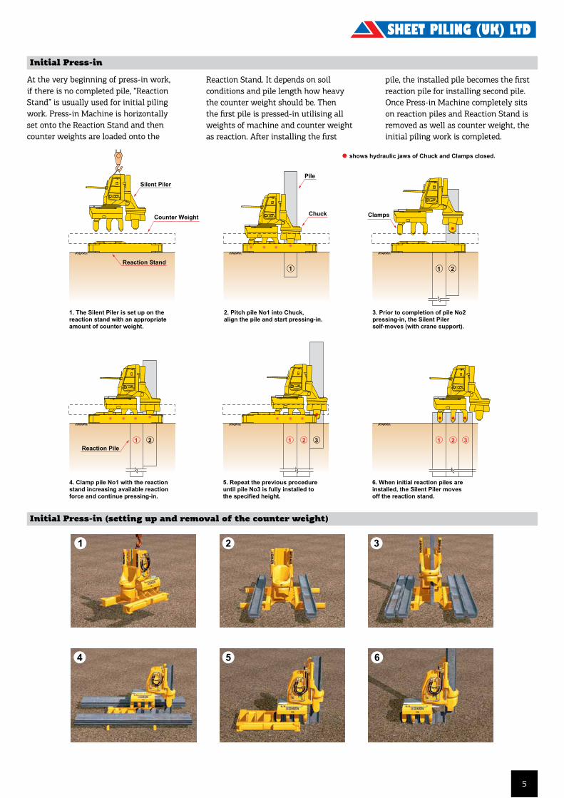
shows hydraulic jaws of Chuck and Clamps closed.
1
32121
2. Pitch pile No1 into Chuck, align the pile and start pressing-in.
1. The Silent Piler is set up on the reaction stand with an appropriate amount of counter weight.
5. Repeat the previous procedure until pile No3 is fully installed to the specified height.
4. Clamp pile No1 with the reaction stand increasing available reaction force and continue pressing-in.
Silent Piler
Reaction Stand
Reaction Pile
Counter WeightChuck
Pile
21
321
3. Prior to completion of pile No2 pressing-in, the Silent Piler self-moves (with crane support).
6. When initial reaction piles are installed, the Silent Piler moves off the reaction stand.
Clamps
Initial Press-in
At the very beginning of press-in work, if there is no completed pile, “Reaction Stand” is usually used for initial piling work. Press-in Machine is horizontally set onto the Reaction Stand and then counter weights are loaded onto the
Reaction Stand. It depends on soil conditions and pile length how heavy the counter weight should be. Then the first pile is pressed-in utilising all weights of machine and counter weight as reaction. After installing the first
downloaded from Giken's corporate home page athttp://www.giken-smp.com/
Copyright © Giken Seisakusho Co., Ltd. All Rights Reserved. Ver. 2.1 / 15 Feb. 2001
When you begin a job, there are usually no piles in the ground from which to start off. The Silent Piler is set up on a "Reaction Stand".
An appropriate amount of counterweight, determined by the ground conditions and length of piles, is placed on the Reaction Stand. The
first pile is then pressed-in deriving reaction force from this combined weight. As each of the initial piles is driven, the Silent PIler moves
forward and clamps onto that pile, thus increasing the available reaction force. The initial press-in phase is completed when all the initial
piles have been installed and the Piler has moved off the Reaction Stand onto these piles.
1
4
2
5
3
6
shows hydraulic jaws of Chuck and Clamps closed.
1
32121
2. Pitch pile No1 into Chuck, align the pile and start pressing-in.
1. The Silent Piler is set up on the reaction stand with an appropriate amount of counter weight.
5. Repeat the previous procedure until pile No3 is fully installed to the specified height.
4. Clamp pile No1 with the reaction stand increasing available reaction force and continue pressing-in.
Silent Piler
Reaction Stand
Reaction Pile
Counter WeightChuck
Pile
21
321
3. Prior to completion of pile No2 pressing-in, the Silent Piler self-moves (with crane support).
6. When initial reaction piles are installed, the Silent Piler moves off the reaction stand.
Clamps
Initial Press-in (setting up and removal of the counter weight)
pile, the installed pile becomes the first reaction pile for installing second pile. Once Press-in Machine completely sits on reaction piles and Reaction Stand is removed as well as counter weight, the initial piling work is completed.
5

Curve Installation
Chuck rotation, mast revolution and clamp right-left mechanisms are equipped on the press-in machine main body. These functions enable to install piles on curved or complicated alignments. The minimal piling radius differs from the pile sections and press-in machine models.
Corner Installation
The press-in machine (U-Piler) has “Corner Four (C4)” function which can install 2 piles for both sides on perpendicular alignment from a machine position. The 2 piles are installed on the pile alignment and the other 2 piles are installed as dummy piles for reaction piles. This Corner 4 function make piling work at narrow site condition safe and efficient for cofferdam works.
For further information on , please access http://www.giken-smp.com/ or contact your nearest Giken office ;
U. S. A Giken America Corporation Tel. +1-407-380-3232 Fax +1-407-380-9411
The Netherlands Giken Europe B.V. Head Office Tel. +31-(0)36-532-8128 Fax +31-(0)36-532-7477
U. K. Giken Europe B.V. London Office Tel. +44-(0)20-8461-6620 Fax +44-(0)20-8461-6621
Germany Giken Europe B.V. Berlin Office Tel. +49-(0)30-4702-3380 Fax +49-(0)30-4702-3382
Singapore Giken Seisakusho Asia Pte., Ltd. Tel. +65-863-0330 Fax +65-863-1141
Japan Giken Seisakusho Co., Ltd. Tel. +81-(0)3-3528-1630 Fax +81-(0)3-3527-6055
downloaded from Giken's corporate home page athttp://www.giken-smp.com/
Copyright © Giken Seisakusho Co., Ltd. All Rights Reserved. Ver. 2.1 / 15 Feb. 2001
Through the use of the revolving mechanism of the Chuck and Mast, the Silent Piler can construct a
curve or other complicated configurations. The minimum radius of the curve varies according to the
pile specifications and Silent Piler model.
The "Corner Four (C4)" function allows the Silent Piler to install up to two piles at right angles to and
on each side of the proposed corner position. Once sufficient numbers of reaction piles are installed,
a service crane simply lifts the Silent Piler off the initial line onto the new line.
L2 L1 R1 R2
Auxiliary techniques are primarily used to enable piles to be pressed into difficult ground conditions.
Additionally, they can be utilized as a means to significantly improve productivity and hence costs,
as well as optimizing the sheet pile section required. Water jetting is effected by means of either a
high strength steel jetting pipe (lance) or by utilizing the newly developed high pressure flexible
hose supplied from a reel system (Super Jet Reel) atop the Silent Piler, attached to the inner face
of the sheet pile.
Effect of water jetting :1. Water jetting loosens granular soils and softens cohesive soils at the pile toe locally and temporarily to reduce toe resistance.
2. Water jetting lubricates the surface of pile to reduce skin friction.
Water jetting does not1. create large voids in the soil.
2. have any long term effects on soil strength.
Minimun radius
PRESS-IN METHOD
For further information on , please access http://www.giken-smp.com/ or contact your nearest Giken office ;
U. S. A Giken America Corporation Tel. +1-407-380-3232 Fax +1-407-380-9411
The Netherlands Giken Europe B.V. Head Office Tel. +31-(0)36-532-8128 Fax +31-(0)36-532-7477
U. K. Giken Europe B.V. London Office Tel. +44-(0)20-8461-6620 Fax +44-(0)20-8461-6621
Germany Giken Europe B.V. Berlin Office Tel. +49-(0)30-4702-3380 Fax +49-(0)30-4702-3382
Singapore Giken Seisakusho Asia Pte., Ltd. Tel. +65-863-0330 Fax +65-863-1141
Japan Giken Seisakusho Co., Ltd. Tel. +81-(0)3-3528-1630 Fax +81-(0)3-3527-6055
downloaded from Giken's corporate home page athttp://www.giken-smp.com/
Copyright © Giken Seisakusho Co., Ltd. All Rights Reserved. Ver. 2.1 / 15 Feb. 2001
Through the use of the revolving mechanism of the Chuck and Mast, the Silent Piler can construct a
curve or other complicated configurations. The minimum radius of the curve varies according to the
pile specifications and Silent Piler model.
The "Corner Four (C4)" function allows the Silent Piler to install up to two piles at right angles to and
on each side of the proposed corner position. Once sufficient numbers of reaction piles are installed,
a service crane simply lifts the Silent Piler off the initial line onto the new line.
L2 L1 R1 R2
Auxiliary techniques are primarily used to enable piles to be pressed into difficult ground conditions.
Additionally, they can be utilized as a means to significantly improve productivity and hence costs,
as well as optimizing the sheet pile section required. Water jetting is effected by means of either a
high strength steel jetting pipe (lance) or by utilizing the newly developed high pressure flexible
hose supplied from a reel system (Super Jet Reel) atop the Silent Piler, attached to the inner face
of the sheet pile.
Effect of water jetting :1. Water jetting loosens granular soils and softens cohesive soils at the pile toe locally and temporarily to reduce toe resistance.
2. Water jetting lubricates the surface of pile to reduce skin friction.
Water jetting does not1. create large voids in the soil.
2. have any long term effects on soil strength.
Minimun radius
SHEET PILING VIDEOS
Vibration Free Piling (HD)
To watch these videos please visit our website: https://www.sheetpilinguk.com/about/useful-videos/
Vibration Free Piling Press
Corner Sheet Piling
Initial Setup
Initial Set Up - Reaction Stand Water Jetting Sheet Piles
6

7
Power PackEngine Unit Type EU 300
Power Source Diesel Engine (Tier 111B)
Rated Output 230 kW (313 PS)
Fuel Tank 500 L
Hydraulic Oil 490 L
Noise Level at 7m 69 dB (A)
Weight 6,400 kg
Reaction StandWeight 1,900 kg
F201 SILENT PILERSilent Piler
Power Pack
Reaction Stand
F201 Silent PilerSilent Pile Range U Profile 600 mm
Max. Installation Force 1,500 kN
Max Extraction Force 1,600 kN
Stroke 850 mm
Pressing-in Speed 1.4 - 30.0 m/min
Drawing-out Speed 1.1 - 23.2 m/min
Operation Radio Control
Movement Self-moving
Power Unit Type EU 300 Crawler Unit
Silent Piler Weight 11,120 kg
Super Jet Reel Weight 820 kg
Total Machine Weight 11,940 kg
6
The above specifications are subject to alteration without prior notice
5
Su
per
Cru
sh M
od
e
400mm wide 500mm wide 600mm wide F201 Specifications
Reaction Stand
2020
4650
490
5600
At Transportation 3450
Reaction Stand (with Leveling Jack)
Mass 1900 kg
Power Unit
1800
1960 3975
2350 18
0554
5
2110
Power Unit
Diesel Engine
230 kW(313 ps)/1800 min-1
204 kW(278 ps)/1600 min-1
179 kW(243 ps)/1400 min-1
500 L
Piler ECO Oil 490 L
1.4 km/h
6400 kg (with 20m Hose)
EU300 I3
Power Source
Rated Output
Fuel Tank Capacity
Hydraulic Reservoir
Moving Speed
Mass
Power Mode
Eco Mode
Super Eco Mode
F201-C400 F201-C500 F201-C600
F201-400 F201-500 F201-600
F201-400 F201-500 F201-600
Chuck Mass
Standard Mode ChuckSheet Pile Width Super Crush Mode Chuck
2850 kg 3400 kg
2550 kg
500, 600 mm
400 mm 2900 kg
Leveling Jack
Wat
er J
etti
ng
Mo
de
Sta
nd
ard
Mo
de
Dimensions & Specifications
MA
X 41
40
At Transportation 3675
MA
X 41
40
At Transportation 3835
MA
X 41
40
At Transportation 3835
Piler Jet Reel
Applicable pile length
Mass
Standard 17.0 m (Max. 27.0 m)
820 kg
JR28
Max. Press-in Force
Max. Extraction Force
Stroke
Press-in Speed
Extraction Speed
Control System
Mass(Main Body & Hose Reel)
800 kN
900 kN
850 mm
0.5 ~ 4.5 m/min
1.1 ~ 9.4 m/min
Radio Control
for 400mm wide sheet pile 13160 kg
for 500, 600mm wide sheet pile 13660 kg
Hose Reel
2810 kg
Pile AugerApplicable pile length(Standard)
Mass
Total Mass
Max 24 m*
1850 kg
for 400mm wide sheet pile 9050 kg
for 500, 600mm wide sheet pile 10050 kg
for 400mm wide sheet pile 10900 kg
for 500, 600mm wide sheet pile 11900 kg
PA22
HR17C
Auger Motor
Casing Auger
At Transportation 2985
2785
MA
X 41
80
2650
At Transportation 3170
2970
MA
X 41
80
2650
Piler Jet ReelJR28
MA
X 41
80
2650
At Transportation 3000
2590
● Super Crush Mode
Max. Press-in Force
Max. Extraction Force
Stroke
Press-in Speed
Extraction Speed
Control System
Mass(Main Body & Piler Jet Reel)
1500 kN
1600 kN
850 mm
1.4 ~ 30.0 m/min
1.1 ~ 23.2 m/min
Radio Control
for 400mm wide sheet pile 10820 kg
for 500, 600mm wide sheet pile 11120 kg
● Water Jetting Mode
Max. Press-in Force
Max. Extraction Force
Stroke
Press-in Speed
Extraction Speed
Control System
Mass(Main Body)
1500 kN
1600 kN
850 mm
1.4 ~ 30.0 m/min
1.1 ~ 23.2 m/min
Radio Control
for 400mm wide sheet pile 10000 kg
for 500, 600mm wide sheet pile 10300 kg
● Standard Mode
2785
2650 MA
X 35
00
for 400mm wideStandard Mode Chuck
for 500-600 mm wideStandard Mode Chuck
for 500-600 mm wideStandard Mode Chuck
MAX
3500
2650
1095
2590 2970
2650 MA
X 35
00
Piler Jet Reel is an optional item
At Extraction
AtTransportation
*Max 30m in special mode
Mass(Standard) (including Hose Reel Bracket)
AtTrans-portation
Hose Reel
Auger Motor
for 400mm wideCasing Auger
for 500,600mm wideCasing Auger
for 500,600mm wideCasing Auger
1265
1200
At T
rans
por
tatio
n 28
35
3350
470
3250
0(F
or s
heet
pile
leng
th 2
4m)
1450
1295
2000
1265
1200
At T
rans
por
tatio
n 28
35
3510
3250
0(F
or s
heet
pile
leng
th 2
4m)
1450
1295
2000
470
1265
1200
At T
rans
por
tatio
n 28
35
3510
3250
0(F
or s
heet
pile
leng
th 2
4m)
1450
1295
2000
470
for 400mm wideSuper CrushMode Chuck
for 500-600mm wideSuper CrushMode Chuck
for 500-600mm wideSuper CrushMode Chuck
1095
1095
7 8
1
2
3
4
5
6
7
0 10 20 30 40 50
*Extrapolated SPT-N Value when over 50.
▼ Borehole Log
Emergency Land Slide Remedial Works
F201 Project Data Sheet
SandyGRAVEL
Gravelmixed SAND
LAVA
U S
heet
Pile
SPⅢ L
= 7
.0 m
F201 Demonstration Test
Project
Location
Period
Silent Piler
Type of Sheet Pile
Pile Length
Emergency Channel Construction Works
Oshima Town, Tokyo
March 2014 ~ May 2014
F201
U Sheet Pile SP Ⅲ7.0 m
:
:
:
:
:
:
Project
Location
Period
Silent Piler
Type of Sheet Pile
Pile Length
Cofferdam Test Piling
Dong Gang Business District, Dalian China
November 2013 ~ December 2013
F201
U Sheet Pile SP Ⅳ12m (Standard Mode)
12m, 24m (Super Crush Mode)
:
:
:
:
:
:
150
75
Refusal
Refusal
Refusal
Refusal
Refusal
Roller Holder
Pile RollerPile Roller
Accessories
Standard Accessories
Optional Accessories
Auger Head ReplacementAttachment *
Casing Scraper *
Casing Scraper
Casing
Hose Roller
Hose Roller
Cable HangerCable Hanger
Pile Laser
Piler Jet Reel (JR28)
Piler Stage Chuck Stage *
Auger Head *
Pile Roller Module Box
* Available for Super Crush Mode only.
■ 400mm wide ■ 500-600mm wide
φ400 Twin Blades
φ580 Twin Blades (Retractable) φ685 Triple Blades
φ540 Twin Blades
φ450 Triple Blades φ540 Triple Blades
φ330 Twin Blades φ450 Twin Blades
*
* for 600mm wide only
φ540 Triple Blades
1
2
3
4
5
6
7
8
9
10
11
12
13
14
15
16
17
18
19
20
21
22
23
▼ Borehole Log
MUD
Muddy CLAY
Fine SAND
ModeratelyWeathered DIABASE
U S
heet
Pile
SPⅣ
L =
24.
0 m
6
The above specifications are subject to alteration without prior notice
5
Su
per
Cru
sh M
od
e
400mm wide 500mm wide 600mm wide F201 Specifications
Reaction Stand
2020
4650
490
5600
At Transportation 3450
Reaction Stand (with Leveling Jack)
Mass 1900 kg
Power Unit
1800
1960 3975
2350 18
0554
5
2110
Power Unit
Diesel Engine
230 kW(313 ps)/1800 min-1
204 kW(278 ps)/1600 min-1
179 kW(243 ps)/1400 min-1
500 L
Piler ECO Oil 490 L
1.4 km/h
6400 kg (with 20m Hose)
EU300 I3
Power Source
Rated Output
Fuel Tank Capacity
Hydraulic Reservoir
Moving Speed
Mass
Power Mode
Eco Mode
Super Eco Mode
F201-C400 F201-C500 F201-C600
F201-400 F201-500 F201-600
F201-400 F201-500 F201-600
Chuck Mass
Standard Mode ChuckSheet Pile Width Super Crush Mode Chuck
2850 kg 3400 kg
2550 kg
500, 600 mm
400 mm 2900 kg
Leveling Jack
Wat
er J
etti
ng
Mo
de
Sta
nd
ard
Mo
de
Dimensions & Specifications
MA
X 41
40
At Transportation 3675
MA
X 41
40
At Transportation 3835
MA
X 41
40
At Transportation 3835
Piler Jet Reel
Applicable pile length
Mass
Standard 17.0 m (Max. 27.0 m)
820 kg
JR28
Max. Press-in Force
Max. Extraction Force
Stroke
Press-in Speed
Extraction Speed
Control System
Mass(Main Body & Hose Reel)
800 kN
900 kN
850 mm
0.5 ~ 4.5 m/min
1.1 ~ 9.4 m/min
Radio Control
for 400mm wide sheet pile 13160 kg
for 500, 600mm wide sheet pile 13660 kg
Hose Reel
2810 kg
Pile AugerApplicable pile length(Standard)
Mass
Total Mass
Max 24 m*
1850 kg
for 400mm wide sheet pile 9050 kg
for 500, 600mm wide sheet pile 10050 kg
for 400mm wide sheet pile 10900 kg
for 500, 600mm wide sheet pile 11900 kg
PA22
HR17C
Auger Motor
Casing Auger
At Transportation 2985
2785
MA
X 41
80
2650
At Transportation 3170
2970
MA
X 41
80
2650
Piler Jet ReelJR28
MA
X 41
80
2650
At Transportation 3000
2590
● Super Crush Mode
Max. Press-in Force
Max. Extraction Force
Stroke
Press-in Speed
Extraction Speed
Control System
Mass(Main Body & Piler Jet Reel)
1500 kN
1600 kN
850 mm
1.4 ~ 30.0 m/min
1.1 ~ 23.2 m/min
Radio Control
for 400mm wide sheet pile 10820 kg
for 500, 600mm wide sheet pile 11120 kg
● Water Jetting Mode
Max. Press-in Force
Max. Extraction Force
Stroke
Press-in Speed
Extraction Speed
Control System
Mass(Main Body)
1500 kN
1600 kN
850 mm
1.4 ~ 30.0 m/min
1.1 ~ 23.2 m/min
Radio Control
for 400mm wide sheet pile 10000 kg
for 500, 600mm wide sheet pile 10300 kg
● Standard Mode
2785
2650 MA
X 35
00
for 400mm wideStandard Mode Chuck
for 500-600 mm wideStandard Mode Chuck
for 500-600 mm wideStandard Mode Chuck
MAX
3500
2650
1095
2590 2970
2650 MA
X 35
00
Piler Jet Reel is an optional item
At Extraction
AtTransportation
*Max 30m in special mode
Mass(Standard) (including Hose Reel Bracket)
AtTrans-portation
Hose Reel
Auger Motor
for 400mm wideCasing Auger
for 500,600mm wideCasing Auger
for 500,600mm wideCasing Auger
1265
1200
At T
rans
por
tatio
n 28
35
3350
470
3250
0(F
or s
heet
pile
leng
th 2
4m)
1450
1295
2000
1265
1200
At T
rans
por
tatio
n 28
35
3510
3250
0(F
or s
heet
pile
leng
th 2
4m)
1450
1295
2000
470
1265
1200
At T
rans
por
tatio
n 28
35
3510
3250
0(F
or s
heet
pile
leng
th 2
4m)
1450
1295
2000
470
for 400mm wideSuper CrushMode Chuck
for 500-600mm wideSuper CrushMode Chuck
for 500-600mm wideSuper CrushMode Chuck
1095
1095

Super Jet Reel and Crawlerare optional equipment.
Silent Piler
Power Pack
Reaction Stand
U Profile500, 525, 600 mm
Max. Installation Force 1 500 kNMax. Extraction Force 1 600 kNStroke 800 mmPressing-in Speed 1.4 - 22.7 m/minDrawing-out Speed 2.2 - 17.6 m/minOperation Radio ControlMovement Self-moving Silent Piler 9 400 kg Super Jet Reel 620 kg (Optional)Total Weight 10 020 kg
Engine Unit Type EU 200Power Source Diesel EngineRated Output 147 kW (200 PS)Fuel Tank 350 LHydraulic Oil 550 LNoise Level at 7m 69 dB (A)Weight 4 900 kgCrawler Type GT1 (Optional)Crawler Operation Remote ControlPower Source 2 Pumps x 2 MotorsMoving Speed 1.4 km/hWeight 1 000 kgTotal Weight 5 900 kg
Weight 2 000 kg
Power Pack
Reaction Stand
* Specifications are subject to alteration without prior notice.
For further information on The Giken Silent Piler, please consult your nearest Giken office ;
U. S. A Giken America Corporation Tel. +1-407-380-3232 Fax +1-407-380-9411
The Netherlands Giken Europe B.V. Head Office Tel. +31-(0)36-532-8128 Fax +31-(0)36-532-7477
U. K. Giken Europe B.V. London Office Tel. +44-(0)20-8461-6620 Fax +44-(0)20-8461-6621
Germany Giken Europe B.V. Berlin Office Tel. +49-(0)30-4702-3380 Fax +49-(0)30-4702-3382
Singapore Giken Seisakusho Asia Pte., Ltd. Tel. +65-863-0330 Fax +65-863-1141
Japan Giken Seisakusho Co., Ltd. Tel. +81-(0)3-3528-1630 Fax +81-(0)3-3527-6055
Sheet Pile Range
Weight
1705
1600 2100
4150
570
1780
2350
2120
5060
520
3380
6210
2570
335535
70
Max
. 404
5
1145
2570 (600 mm pile)26
00
475
2850
Hose Extraction Position
Transportation Position
600mm
U ProfileSteel Sheet Pile
SuperJet Reel
Metric Unit
downloaded from Giken's corporate home page athttp://www.giken-smp.com/
Copyright © Giken Seisakusho Co., Ltd. All Rights Reserved. Ver. 1.0
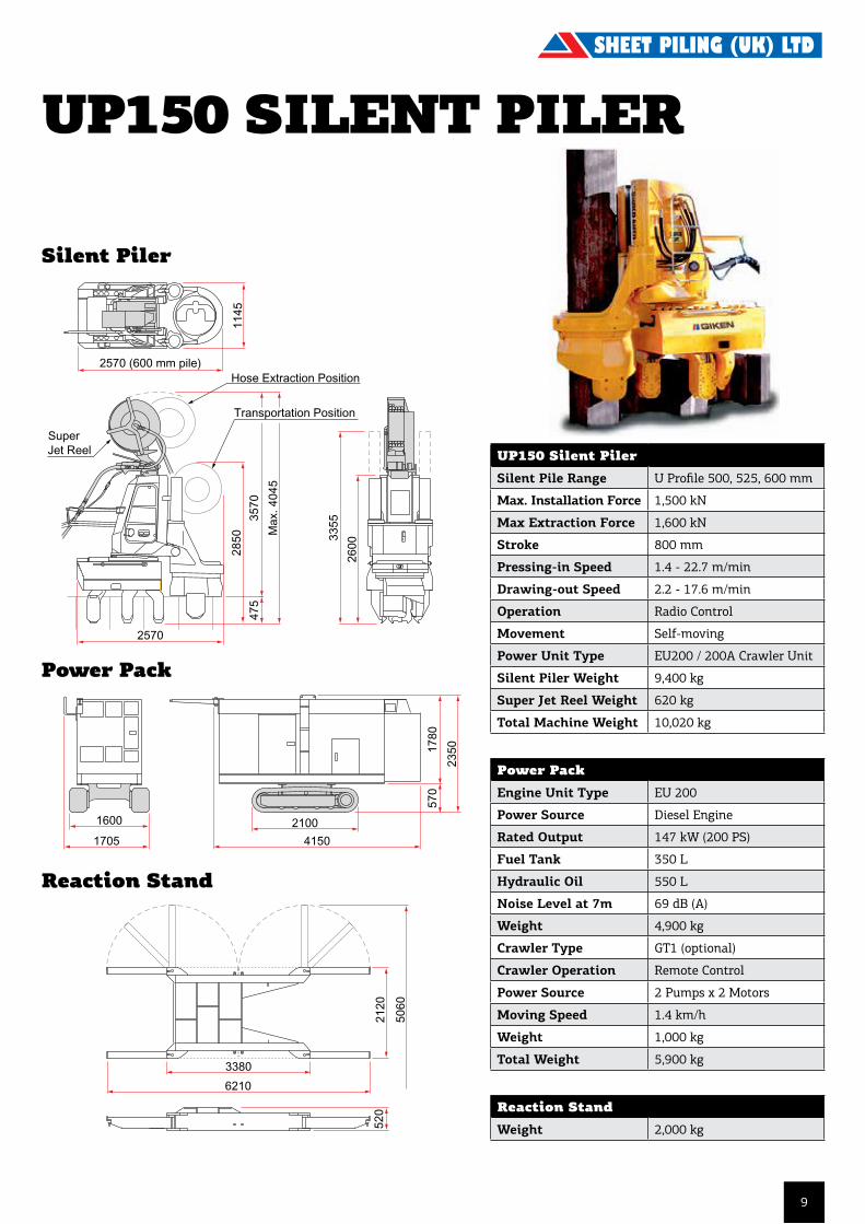
Power PackEngine Unit Type EU 200
Power Source Diesel Engine
Rated Output 147 kW (200 PS)
Fuel Tank 350 L
Hydraulic Oil 550 L
Noise Level at 7m 69 dB (A)
Weight 4,900 kg
Crawler Type GT1 (optional)
Crawler Operation Remote Control
Power Source 2 Pumps x 2 Motors
Moving Speed 1.4 km/h
Weight 1,000 kg
Total Weight 5,900 kg
Reaction StandWeight 2,000 kg
SW100 SILENT PILERSilent Piler
Power Pack
Reaction Stand
Super Jet Reel and Crawlerare optional equipment.
Silent Piler
Power Pack
Reaction Stand
U Profile500, 525, 600 mm
Max. Installation Force 1 500 kNMax. Extraction Force 1 600 kNStroke 800 mmPressing-in Speed 1.4 - 22.7 m/minDrawing-out Speed 2.2 - 17.6 m/minOperation Radio ControlMovement Self-moving Silent Piler 9 400 kg Super Jet Reel 620 kg (Optional)Total Weight 10 020 kg
Engine Unit Type EU 200Power Source Diesel EngineRated Output 147 kW (200 PS)Fuel Tank 350 LHydraulic Oil 550 LNoise Level at 7m 69 dB (A)Weight 4 900 kgCrawler Type GT1 (Optional)Crawler Operation Remote ControlPower Source 2 Pumps x 2 MotorsMoving Speed 1.4 km/hWeight 1 000 kgTotal Weight 5 900 kg
Weight 2 000 kg
Power Pack
Reaction Stand
* Specifications are subject to alteration without prior notice.
For further information on The Giken Silent Piler, please consult your nearest Giken office ;
U. S. A Giken America Corporation Tel. +1-407-380-3232 Fax +1-407-380-9411
The Netherlands Giken Europe B.V. Head Office Tel. +31-(0)36-532-8128 Fax +31-(0)36-532-7477
U. K. Giken Europe B.V. London Office Tel. +44-(0)20-8461-6620 Fax +44-(0)20-8461-6621
Germany Giken Europe B.V. Berlin Office Tel. +49-(0)30-4702-3380 Fax +49-(0)30-4702-3382
Singapore Giken Seisakusho Asia Pte., Ltd. Tel. +65-863-0330 Fax +65-863-1141
Japan Giken Seisakusho Co., Ltd. Tel. +81-(0)3-3528-1630 Fax +81-(0)3-3527-6055
Sheet Pile Range
Weight
1705
1600 2100
4150
570
1780
2350
2120
5060
520
3380
6210
2570
335535
70
Max
. 404
5
1145
2570 (600 mm pile)
2600
475
2850
Hose Extraction Position
Transportation Position
600mm
U ProfileSteel Sheet Pile
SuperJet Reel
Metric Unit
downloaded from Giken's corporate home page athttp://www.giken-smp.com/
Copyright © Giken Seisakusho Co., Ltd. All Rights Reserved. Ver. 1.0
SW100 Silent PilerSilent Pile Range U Profile 500, 525, 600 mm
Max. Installation Force 1,000 kN
Max Extraction Force 1,100 kN
Stroke 750 mm
Pressing-in Speed 1.5 - 35.2 m/min
Drawing-out Speed 3.2 - 27.5 m/min
Operation Radio Control
Movement Self-moving
Power Unit Type EU200 / 200A Crawler Unit
Silent Piler Weight 8,200 kg
Super Jet Reel Weight 550 kg
Total Machine Weight 8,750 kg
8
Super Jet Reel and Crawlerare optional equipment.
Silent Piler
Power Pack
Reaction Stand
U Profile500, 525, 600 mm
Max. Installation Force 1 500 kNMax. Extraction Force 1 600 kNStroke 800 mmPressing-in Speed 1.4 - 22.7 m/minDrawing-out Speed 2.2 - 17.6 m/minOperation Radio ControlMovement Self-moving Silent Piler 9 400 kg Super Jet Reel 620 kg (Optional)Total Weight 10 020 kg
Engine Unit Type EU 200Power Source Diesel EngineRated Output 147 kW (200 PS)Fuel Tank 350 LHydraulic Oil 550 LNoise Level at 7m 69 dB (A)Weight 4 900 kgCrawler Type GT1 (Optional)Crawler Operation Remote ControlPower Source 2 Pumps x 2 MotorsMoving Speed 1.4 km/hWeight 1 000 kgTotal Weight 5 900 kg
Weight 2 000 kg
Power Pack
Reaction Stand
* Specifications are subject to alteration without prior notice.
For further information on The Giken Silent Piler, please consult your nearest Giken office ;
U. S. A Giken America Corporation Tel. +1-407-380-3232 Fax +1-407-380-9411
The Netherlands Giken Europe B.V. Head Office Tel. +31-(0)36-532-8128 Fax +31-(0)36-532-7477
U. K. Giken Europe B.V. London Office Tel. +44-(0)20-8461-6620 Fax +44-(0)20-8461-6621
Germany Giken Europe B.V. Berlin Office Tel. +49-(0)30-4702-3380 Fax +49-(0)30-4702-3382
Singapore Giken Seisakusho Asia Pte., Ltd. Tel. +65-863-0330 Fax +65-863-1141
Japan Giken Seisakusho Co., Ltd. Tel. +81-(0)3-3528-1630 Fax +81-(0)3-3527-6055
Sheet Pile Range
Weight
1705
1600 2100
4150
570
1780
2350
2120
5060
520
3380
6210
2570
335535
70
Max
. 404
5
1145
2570 (600 mm pile)
2600
475
2850
Hose Extraction Position
Transportation Position
600mm
U ProfileSteel Sheet Pile
SuperJet Reel
Metric Unit
downloaded from Giken's corporate home page athttp://www.giken-smp.com/
Copyright © Giken Seisakusho Co., Ltd. All Rights Reserved. Ver. 1.0
Super Jet Reel and Crawlerare optional equipment.
Silent Piler
Power Pack
Reaction Stand
U Profile500, 525, 600 mm
Max. Installation Force 1 500 kNMax. Extraction Force 1 600 kNStroke 800 mmPressing-in Speed 1.4 - 22.7 m/minDrawing-out Speed 2.2 - 17.6 m/minOperation Radio ControlMovement Self-moving Silent Piler 9 400 kg Super Jet Reel 620 kg (Optional)Total Weight 10 020 kg
Engine Unit Type EU 200Power Source Diesel EngineRated Output 147 kW (200 PS)Fuel Tank 350 LHydraulic Oil 550 LNoise Level at 7m 69 dB (A)Weight 4 900 kgCrawler Type GT1 (Optional)Crawler Operation Remote ControlPower Source 2 Pumps x 2 MotorsMoving Speed 1.4 km/hWeight 1 000 kgTotal Weight 5 900 kg
Weight 2 000 kg
Power Pack
Reaction Stand
* Specifications are subject to alteration without prior notice.
For further information on The Giken Silent Piler, please consult your nearest Giken office ;
U. S. A Giken America Corporation Tel. +1-407-380-3232 Fax +1-407-380-9411
The Netherlands Giken Europe B.V. Head Office Tel. +31-(0)36-532-8128 Fax +31-(0)36-532-7477
U. K. Giken Europe B.V. London Office Tel. +44-(0)20-8461-6620 Fax +44-(0)20-8461-6621
Germany Giken Europe B.V. Berlin Office Tel. +49-(0)30-4702-3380 Fax +49-(0)30-4702-3382
Singapore Giken Seisakusho Asia Pte., Ltd. Tel. +65-863-0330 Fax +65-863-1141
Japan Giken Seisakusho Co., Ltd. Tel. +81-(0)3-3528-1630 Fax +81-(0)3-3527-6055
Sheet Pile Range
Weight
1705
1600 2100
4150
570
1780
2350
2120
5060
520
3380
6210
2570
335535
70
Max
. 404
5
1145
2570 (600 mm pile)26
00
475
2850
Hose Extraction Position
Transportation Position
600mm
U ProfileSteel Sheet Pile
SuperJet Reel
Metric Unit
downloaded from Giken's corporate home page athttp://www.giken-smp.com/
Copyright © Giken Seisakusho Co., Ltd. All Rights Reserved. Ver. 1.0
Power PackEngine Unit Type EU 200
Power Source Diesel Engine
Rated Output 147 kW (200 PS)
Fuel Tank 350 L
Hydraulic Oil 550 L
Noise Level at 7m 69 dB (A)
Weight 4,900 kg
Crawler Type GT1 (optional)
Crawler Operation Remote Control
Power Source 2 Pumps x 2 Motors
Moving Speed 1.4 km/h
Weight 1,000 kg
Total Weight 5,900 kg
Reaction StandWeight 2,000 kg
UP150 SILENT PILER
Silent Piler
Power Pack
Reaction Stand
UP150 Silent PilerSilent Pile Range U Profile 500, 525, 600 mm
Max. Installation Force 1,500 kN
Max Extraction Force 1,600 kN
Stroke 800 mm
Pressing-in Speed 1.4 - 22.7 m/min
Drawing-out Speed 2.2 - 17.6 m/min
Operation Radio Control
Movement Self-moving
Power Unit Type EU200 / 200A Crawler Unit
Silent Piler Weight 9,400 kg
Super Jet Reel Weight 620 kg
Total Machine Weight 10,020 kg
9

Super Jet Reel and Crawlerare optional equipment.
Silent Piler
Power Pack
Reaction Stand
AZ13, 18, 26, 36, 48H1200, 1700, 2500, 3600
Max. Installation Force 1 000 kNMax. Extraction Force 1 200 kNStroke 700 mmPressing-in Speed 1.5 - 35.2 m/minDrawing-out Speed 2.6 - 27.5 m/minOperation Radio ControlMovement Self-moving Silent Piler 11 450 kg Super Jet Reel 680 kg (Optional)Total Weight 12 130 kg
Engine Unit Type EU 200Power Source Diesel EngineRated Output 147 kW (200 PS)Fuel Tank 350 LHydraulic Oil 550 LNoise Level at 7m 69 dB (A)Weight 4 900 kgCrawler Type GT1 (Optional)Crawler Operation Remote ControlPower Source 2 Pumps x 2 MotorsMoving Speed 1.4 km/hWeight 1 000 kgTotal Weight 5 900 kg
Weight 2 100 kg
Power Pack
Reaction Stand
* Specifications are subject to alteration without prior notice.
For further information on The Giken Silent Piler, please consult your nearest Giken office ;
U. S. A Giken America Corporation Tel. +1-407-380-3232 Fax +1-407-380-9411
The Netherlands Giken Europe B.V. Head Office Tel. +31-(0)36-532-8128 Fax +31-(0)36-532-7477
U. K. Giken Europe B.V. London Office Tel. +44-(0)20-8461-6620 Fax +44-(0)20-8461-6621
Germany Giken Europe B.V. Berlin Office Tel. +49-(0)30-4702-3380 Fax +49-(0)30-4702-3382
Singapore Giken Seisakusho Asia Pte., Ltd. Tel. +65-863-0330 Fax +65-863-1141
Japan Giken Seisakusho Co., Ltd. Tel. +81-(0)3-3528-1630 Fax +81-(0)3-3527-6055
Sheet Pile Range
Weight
1705
1600 2100
4150
570
1780
2350
5650
2200
527
7220
3880
Hose Extraction Position
3130
2865
475
2590
Max
. 408
0
3605
1260
3390 (Transportation)
3570 (AZ26)3560 (H2500)
3570 (AZ26)
Transportation Position SuperJet Reel
Z ProfileSteel Sheet Pile
AZSection
HoeschSection
downloaded from Giken's corporate home page athttp://www.giken-smp.com/
Copyright © Giken Seisakusho Co., Ltd. All Rights Reserved. Ver. 1.0
Power PackEngine Unit Type EU 200
Power Source Diesel Engine
Rated Output 147 kW (200 PS)
Fuel Tank 350 L
Hydraulic Oil 550 L
Noise Level at 7m 69 dB (A)
Weight 4,900 kg
Crawler Type GT1 (optional)
Crawler Operation Remote Control
Power Source 2 Pumps x 2 Motors
Moving Speed 1.4 km/h
Weight 1,000 kg
Total Weight 5,900 kg
Reaction StandWeight 2,100 kg
ZP100 SILENT PILERSilent Piler
Reaction Stand
Super Jet Reel and Crawlerare optional equipment.
Silent Piler
Power Pack
Reaction Stand
AZ13, 18, 26, 36, 48H1200, 1700, 2500, 3600
Max. Installation Force 1 000 kNMax. Extraction Force 1 200 kNStroke 700 mmPressing-in Speed 1.5 - 35.2 m/minDrawing-out Speed 2.6 - 27.5 m/minOperation Radio ControlMovement Self-moving Silent Piler 11 450 kg Super Jet Reel 680 kg (Optional)Total Weight 12 130 kg
Engine Unit Type EU 200Power Source Diesel EngineRated Output 147 kW (200 PS)Fuel Tank 350 LHydraulic Oil 550 LNoise Level at 7m 69 dB (A)Weight 4 900 kgCrawler Type GT1 (Optional)Crawler Operation Remote ControlPower Source 2 Pumps x 2 MotorsMoving Speed 1.4 km/hWeight 1 000 kgTotal Weight 5 900 kg
Weight 2 100 kg
Power Pack
Reaction Stand
* Specifications are subject to alteration without prior notice.
For further information on The Giken Silent Piler, please consult your nearest Giken office ;
U. S. A Giken America Corporation Tel. +1-407-380-3232 Fax +1-407-380-9411
The Netherlands Giken Europe B.V. Head Office Tel. +31-(0)36-532-8128 Fax +31-(0)36-532-7477
U. K. Giken Europe B.V. London Office Tel. +44-(0)20-8461-6620 Fax +44-(0)20-8461-6621
Germany Giken Europe B.V. Berlin Office Tel. +49-(0)30-4702-3380 Fax +49-(0)30-4702-3382
Singapore Giken Seisakusho Asia Pte., Ltd. Tel. +65-863-0330 Fax +65-863-1141
Japan Giken Seisakusho Co., Ltd. Tel. +81-(0)3-3528-1630 Fax +81-(0)3-3527-6055
Sheet Pile Range
Weight
1705
1600 2100
4150
570
1780
2350
5650
2200
527
7220
3880
Hose Extraction Position
3130
2865
475
2590
Max
. 408
0
3605
1260
3390 (Transportation)
3570 (AZ26)3560 (H2500)
3570 (AZ26)
Transportation Position SuperJet Reel
Z ProfileSteel Sheet Pile
AZSection
HoeschSection
downloaded from Giken's corporate home page athttp://www.giken-smp.com/
Copyright © Giken Seisakusho Co., Ltd. All Rights Reserved. Ver. 1.0
ZP100 Silent PilerSilent Pile Range Z Profile 630 mm
Max. Installation Force 1,000 kN
Max Extraction Force 1,200 kN
Stroke 700 mm
Pressing-in Speed 1.5 - 35.2 m/min
Drawing-out Speed 2.6 - 27.5 m/min
Operation Radio Control
Movement Self-moving
Power Unit Type EU200 Crawler Unit
Silent Piler Weight 11,450 kg
Super Jet Reel Weight 680 kg
Total Machine Weight 12,130 kg
Super Jet Reel and Crawlerare optional equipment.
Silent Piler
Power Pack
Reaction Stand
AZ13, 18, 26, 36, 48H1200, 1700, 2500, 3600
Max. Installation Force 1 000 kNMax. Extraction Force 1 200 kNStroke 700 mmPressing-in Speed 1.5 - 35.2 m/minDrawing-out Speed 2.6 - 27.5 m/minOperation Radio ControlMovement Self-moving Silent Piler 11 450 kg Super Jet Reel 680 kg (Optional)Total Weight 12 130 kg
Engine Unit Type EU 200Power Source Diesel EngineRated Output 147 kW (200 PS)Fuel Tank 350 LHydraulic Oil 550 LNoise Level at 7m 69 dB (A)Weight 4 900 kgCrawler Type GT1 (Optional)Crawler Operation Remote ControlPower Source 2 Pumps x 2 MotorsMoving Speed 1.4 km/hWeight 1 000 kgTotal Weight 5 900 kg
Weight 2 100 kg
Power Pack
Reaction Stand
* Specifications are subject to alteration without prior notice.
For further information on The Giken Silent Piler, please consult your nearest Giken office ;
U. S. A Giken America Corporation Tel. +1-407-380-3232 Fax +1-407-380-9411
The Netherlands Giken Europe B.V. Head Office Tel. +31-(0)36-532-8128 Fax +31-(0)36-532-7477
U. K. Giken Europe B.V. London Office Tel. +44-(0)20-8461-6620 Fax +44-(0)20-8461-6621
Germany Giken Europe B.V. Berlin Office Tel. +49-(0)30-4702-3380 Fax +49-(0)30-4702-3382
Singapore Giken Seisakusho Asia Pte., Ltd. Tel. +65-863-0330 Fax +65-863-1141
Japan Giken Seisakusho Co., Ltd. Tel. +81-(0)3-3528-1630 Fax +81-(0)3-3527-6055
Sheet Pile Range
Weight
1705
1600 2100
4150
570
1780
2350
5650
2200
527
7220
3880
Hose Extraction Position
3130
2865
475
2590
Max
. 408
0
3605
1260
3390 (Transportation)
3570 (AZ26)3560 (H2500)
3570 (AZ26)
Transportation Position SuperJet Reel
Z ProfileSteel Sheet Pile
AZSection
HoeschSection
downloaded from Giken's corporate home page athttp://www.giken-smp.com/
Copyright © Giken Seisakusho Co., Ltd. All Rights Reserved. Ver. 1.0
10
Super Jet Reel and Crawlerare optional equipment.
Silent Piler
Power Pack
Reaction Stand
AZ13, 18, 26, 36, 48H1200, 1700, 2500, 3600
Max. Installation Force 1 000 kNMax. Extraction Force 1 200 kNStroke 700 mmPressing-in Speed 1.5 - 35.2 m/minDrawing-out Speed 2.6 - 27.5 m/minOperation Radio ControlMovement Self-moving Silent Piler 11 450 kg Super Jet Reel 680 kg (Optional)Total Weight 12 130 kg
Engine Unit Type EU 200Power Source Diesel EngineRated Output 147 kW (200 PS)Fuel Tank 350 LHydraulic Oil 550 LNoise Level at 7m 69 dB (A)Weight 4 900 kgCrawler Type GT1 (Optional)Crawler Operation Remote ControlPower Source 2 Pumps x 2 MotorsMoving Speed 1.4 km/hWeight 1 000 kgTotal Weight 5 900 kg
Weight 2 100 kg
Power Pack
Reaction Stand
* Specifications are subject to alteration without prior notice.
For further information on The Giken Silent Piler, please consult your nearest Giken office ;
U. S. A Giken America Corporation Tel. +1-407-380-3232 Fax +1-407-380-9411
The Netherlands Giken Europe B.V. Head Office Tel. +31-(0)36-532-8128 Fax +31-(0)36-532-7477
U. K. Giken Europe B.V. London Office Tel. +44-(0)20-8461-6620 Fax +44-(0)20-8461-6621
Germany Giken Europe B.V. Berlin Office Tel. +49-(0)30-4702-3380 Fax +49-(0)30-4702-3382
Singapore Giken Seisakusho Asia Pte., Ltd. Tel. +65-863-0330 Fax +65-863-1141
Japan Giken Seisakusho Co., Ltd. Tel. +81-(0)3-3528-1630 Fax +81-(0)3-3527-6055
Sheet Pile Range
Weight
1705
1600 2100
4150
570
1780
2350
5650
2200
527
7220
3880
Hose Extraction Position
3130
2865
475
2590
Max
. 408
0
3605
1260
3390 (Transportation)
3570 (AZ26)3560 (H2500)
3570 (AZ26)
Transportation Position SuperJet Reel
Z ProfileSteel Sheet Pile
AZSection
HoeschSection
downloaded from Giken's corporate home page athttp://www.giken-smp.com/
Copyright © Giken Seisakusho Co., Ltd. All Rights Reserved. Ver. 1.0
Power Pack

STILL WORKER ZU-100 WP-150 WP-100
MAX pressing in force 1,000 kN 1,500 kN 1,000 kN
MAX drawing out force 1,100 kN 1,600 kN 1,100 kN
Stroke 750 mm 800 mm 750 mm
Pressing in speed 3.0-36.0 m/min 1.8-23.0 m/min 3.0-36.0 m/min
Drawing out speed 2.4-28.0 m/min 1.9-18.0 m/min 2.4-28.0 m/min
Tilting device +/- 5 degrees +/- 5 degrees +/- 5 degrees
Mast rotation 180 degrees 180 degrees 180 degrees
Applicable sheet piles Z profile U profile U profile AZ12 to 50 400 mm, 500 mm, 400 mm, 500 mm, AZ17-700 to 600 mm 600 mm AZ41-700, AZ12-700R to AZ14-700R, AZ36-700N to AZ46-700N, H1105 to H3806, PZC13 to PZC39, PZ22 & PZ35
U profile L703 to 755, AU14 to AU26, PU12 to PU32, PU11R to PU15R, L603 to L607N
Operation system Wireless radio control Wireless radio control Wireless radio control & cable remote control & cable remote control & cable remote control
Moving system Self-moving Self-moving Self-moving
Greases Biodegradable Biodegradable Biodegradable greases greases greases
Weight 12,200 kg 9,500 kg 7,400 kg
REACTION STAND ZU-100 WP-150 WP-100
Length (L1) 4,000 mm 3,200 mm 3,200 mm
Length (L2) 6,385 mm 5,465 mm 5,465 mm
Width (W1) 2,200 mm 2,000 mm 2,000 mm
Width (W2) 4,640 mm 4,220 mm 4,220mm
Height 462 mm 475 mm 475 mm
Weight 2,400 kg 1,700 kg 1,700 kg
HYDRAULIC POWER UNIT TE-200C
Power Diesel engine, CAT C7 ACERT, in line 6, direct injection
Output rating 168 kw/1,800 min -1
Pump Variable capacity pump: 790 litres/min
Pressure rating 35 MPa max
Fuel oil tank 350 litres
Hydraulic oil tank 500 litres
Weight 5,500 kg
NB Specifications are subject to alteration without prior notice
ZU-100Still Worker ZU-100 can press-in both Z piles and U piles simply by exchanging the clamps.Z pile range: 559 mm to 708 mmU pile range: 600 mm to 750 mm
WP-100 & WP-150WP-100 and WP-150 can press 400 mm, 500 mm and 600 mm wide U piles.
ZU-100 Still Worker
Specification
Still Worker ZU-100
Still Worker WP-100
Still Worker WP-150
WP-100& WP-150 power unit TE-200C with mobile crawler
ZU-100 power unit TE-200C
ZU & WP Reaction Stands
2490 (400 mm sheet pile)2570 (500 mm sheet pile)2650 (600 mm sheet pile)
2470
0 (P
ile L
engt
h-21
m)
Power PackEngine Unit Type CAT C7
Power Source Diesel Engine
Rated Output 168 kW
Fuel Tank 350 L
Hydraulic Oil 500 L
Noise Level at 7m 69 dB (A)
Weight 5,500 kg
Reaction StandWeight 2,400 kg
ZU100 SILENT PILERSilent Piler
Power Pack
Reaction Stand
ZU100 Silent PilerSilent Pile Range U Profile 600 - 750 mm
Z Profile 585 - 700 mm
Max. Installation Force 1,000 kN
Max Extraction Force 1,100 kN
Stroke 750 mm
Pressing-in Speed 3.0 - 36.0 m/min
Drawing-out Speed 2.4 - 28.0 m/min
Operation Radio Control
Movement Self-moving
Power Unit Type TE - 200C
Silent Piler Weight 12,200 kg
11
2248
2581
1075
3320
2570
2390
3140
1300
1360
3359
1879
1660
2469
3960 1660
1375
2469
143361
4000
2351
2200
1251
1224
6448
400462403 62
12
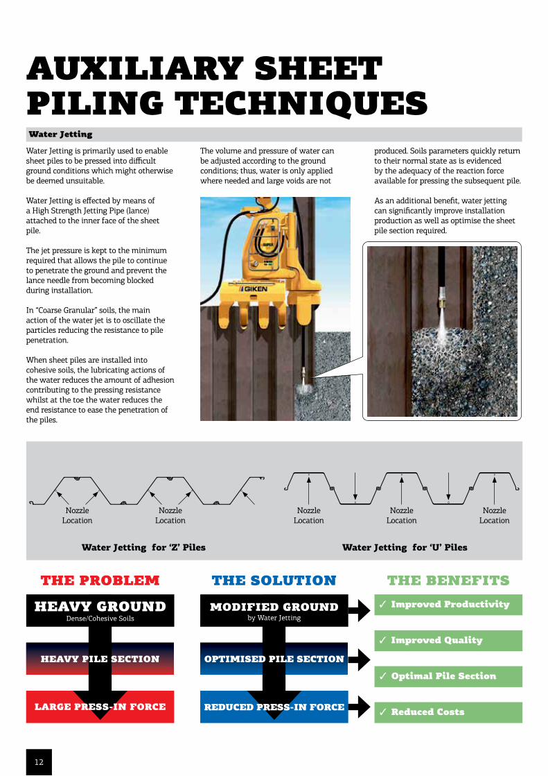
Water Jetting
Water Jetting is primarily used to enable sheet piles to be pressed into difficult ground conditions which might otherwise be deemed unsuitable.
Water Jetting is effected by means of a High Strength Jetting Pipe (lance) attached to the inner face of the sheet pile.
The jet pressure is kept to the minimum required that allows the pile to continue to penetrate the ground and prevent the lance needle from becoming blocked during installation.
In “Coarse Granular” soils, the main action of the water jet is to oscillate the particles reducing the resistance to pile penetration.
When sheet piles are installed into cohesive soils, the lubricating actions of the water reduces the amount of adhesion contributing to the pressing resistance whilst at the toe the water reduces the end resistance to ease the penetration of the piles.
AUXILIARY SHEET PILING TECHNIQUES
=
+
=
+
HEAVY GROUND
HEAVY PILE SECTION
LARGE PRESS-IN FORCE
MODIFIED GROUND
REDUCED PRESS-IN FORCE
3 Improved Productivity
3 Reduced Costs
3 Improved Quality
3 Optimal Pile Section
OPTIMISED PILE SECTION
THE PROBLEM THE SOLUTION THE BENEFITS
Dense/Cohesive Soils by Water Jetting
For further information on , please access http://www.giken-smp.com/ or contact your nearest Giken office ;
U. S. A Giken America Corporation Tel. +1-407-380-3232 Fax +1-407-380-9411
The Netherlands Giken Europe B.V. Head Office Tel. +31-(0)36-532-8128 Fax +31-(0)36-532-7477
U. K. Giken Europe B.V. London Office Tel. +44-(0)20-8461-6620 Fax +44-(0)20-8461-6621
Germany Giken Europe B.V. Berlin Office Tel. +49-(0)30-4702-3380 Fax +49-(0)30-4702-3382
Singapore Giken Seisakusho Asia Pte., Ltd. Tel. +65-863-0330 Fax +65-863-1141
Japan Giken Seisakusho Co., Ltd. Tel. +81-(0)3-3528-1630 Fax +81-(0)3-3527-6055
downloaded from Giken's corporate home page athttp://www.giken-smp.com/
Copyright © Giken Seisakusho Co., Ltd. All Rights Reserved. Ver. 2.1 / 15 Feb. 2001
Through the use of the revolving mechanism of the Chuck and Mast, the Silent Piler can construct a
curve or other complicated configurations. The minimum radius of the curve varies according to the
pile specifications and Silent Piler model.
The "Corner Four (C4)" function allows the Silent Piler to install up to two piles at right angles to and
on each side of the proposed corner position. Once sufficient numbers of reaction piles are installed,
a service crane simply lifts the Silent Piler off the initial line onto the new line.
L2 L1 R1 R2
Auxiliary techniques are primarily used to enable piles to be pressed into difficult ground conditions.
Additionally, they can be utilized as a means to significantly improve productivity and hence costs,
as well as optimizing the sheet pile section required. Water jetting is effected by means of either a
high strength steel jetting pipe (lance) or by utilizing the newly developed high pressure flexible
hose supplied from a reel system (Super Jet Reel) atop the Silent Piler, attached to the inner face
of the sheet pile.
Effect of water jetting :1. Water jetting loosens granular soils and softens cohesive soils at the pile toe locally and temporarily to reduce toe resistance.
2. Water jetting lubricates the surface of pile to reduce skin friction.
Water jetting does not1. create large voids in the soil.
2. have any long term effects on soil strength.
Minimun radius
Water Jetting for ‘Z’ Piles Water Jetting for ‘U’ Piles
Nozzle Location
Nozzle Location
Nozzle Location
Nozzle Location
Nozzle Location
The volume and pressure of water can be adjusted according to the ground conditions; thus, water is only applied where needed and large voids are not
produced. Soils parameters quickly return to their normal state as is evidenced by the adequacy of the reaction force available for pressing the subsequent pile.
As an additional benefit, water jetting can significantly improve installation production as well as optimise the sheet pile section required.

13
Pre-Augering
If dense soils are anticipated, then pre-augering of the sheet pile line in advance of sheet pile installation, to reduce the in-situ ground density, can enable piles to be driven into ground conditions that might otherwise be deemed unsuitable.
Selective Sheet Piling (UK) LTd Telescopic Leader Rigs can be fitted with the MBDA 3000/MBDA 4200 auger motor. A 450mm/600mm diameter auger flight is attached to the auger motor and the ground is then augered through the dense soils. The auger flights are rotated into the ground in one direction and counter-rotated out of the ground leaving the soil in place without flighting the material. Only a small amount of spoil is generated to displace the volume of the auger flight itself.
Use of pre-augering reduces the in-situ density of the soils and prevents a large pressure bulb from forming during driving. The depth of pre-augering is dependant on both method of installation and ground conditions anticipated. Pre-augering can also help identify underground obstructions in advance of pile installation and the system minimises disturbance to the surrounding subsoil.
=
+
=
+
HEAVY GROUND
HEAVY PILE SECTION
LARGE INSTALLATION FORCE
MODIFIED GROUND
REDUCED INSTALLATION FORCE
3 Improved Productivity
3 Reduced Noise and Ground-bourne vibration
3 Improved Quality
3 Optimal Pile Section
OPTIMISED PILE SECTION
THE PROBLEM THE SOLUTION THE BENEFITS
Dense/Cohesive Soils or Boulders/Rock by Pre-Augering
Technical Data Unit 3000 4200-2* BA2200Torque daNm 3000 2100 2200Revolutions (max.) min-1 70 120 50Hydraulic flow rate l/min 450 540 220Required oil quantity per rotation l 6,3 4,4 4,4
Required hydraulic power at auger drive kW 225 270 60Static extraction force (max.) kN 200 200 200Nominal oil pressure MPa 30 30 32Total weight (incl. cardanic joint) kg 1350 1400 600Transport weight kg 1580 1630 700Hexagon connection (SW - M Socket/Female) mm 80 100 80
Dimensions (mm) 3000 4200-2* BA2200H - Height/with swivel 2260/2015 2225/2050 1180B - Width/with swivel 690/910 690/910 710T - Depth 950 970 510R - Guide to drilling axle 600 600 N/AS - Locking to bottom 1970 1970 1050Transport dimensions (without swivel) height (h)/width (b)/depth (t)
2470/1020/1120 2470/1020/1120 N/A
2 3
Bohrantriebe MDBA Auger Drives MDBAAuger Drives MDBA Bohrantriebe MDBA
S
b tB
SH
RT
RT
H
B
hh
tb
H H
B B
20030
9901200
80
DN 65
1730/1600620/850
845525
1440
1855/920/1025
20030
13501580
80
DN 100
2260/2050690/910
950600
1970
2470/1020/1120
20030
14001630
100
DN 100
2225/2050690/910
970600
1970
2470/1020/1120
210070
3104,4
155
11001403102,2
155
300070
4506,3
225
15001203803,1
190
360070
5407,5
270
18001204603,8
230
20030
14001630
100
DN 100
2225/2050690/910
970600
1970
2470/1020/1120
30030
18002030
120
DN 100
2575/2120690/910
970600
2230
2970/1020/1120
420060
5408,8
270
21001205404,4
270
630040
54013,2270
320080
5206,6
260
20030
14001630
100
DN 100
2225/2050690/910
970600
1970
2470/1020/1120
30030
18002030
120
DN 100
2575/2120690/910
970600
2230
2970/1020/1120
420060
5408,8
270
21001205404,4
270
630040
54013,2270
320080
5206,6
260
Technical data MDBA 2100 2100-2* 3000 3000-2* 3500 3500-2*TorqueRevolutions max.Hydraulic flow rateRequired oil quantity per rotationRequired hydr. power at auger driveStatic extraction force max.Nominal oil pressureTotal weight (incl. cardanic joint)Transport weightHexagon connection(SW - M Socket/female)
Concrete swivel (optional)Inner diameter
DimensionsH Height/with swivelB Width/with swivelT DepthR Guide to drilling axleS Locking to bottomTransport dimensions without swivel
Height (h)/width (b)/depth (t)
daNmmin-1
l/minlkWkNMPakgkgmm
mm
mmmmmmmmmm
mm
Technical data MDBA 4200 4200-2* 6000-2 6000-2*daNmmin-1
l/minlkWkNMPakgkgmm
mm
mmmmmmmmmm
mm
TorqueRevolutions max.Hydraulic flow rateRequired oil quantity per rotationRequired hydr. power at auger driveStatic extraction force max.Nominal oil pressureTotal weight (incl. cardanic joint)Transport weightHexagon connection SW - M Socket/female)
Concrete swivel (optional)Inner diameter
DimensionsH Height/with swivelB Width/with swivelT DepthR Guide to drilling axleS Locking to bottomTransport dimensions without swivel
Height (h)/width (b)/depth (t)
DrehmomentDrehzahl max.hydraulischer VolumenstromÖlbedarf pro Umdrehunghydraulische Eckleistungstatische Zugkraft max.ArbeitsdruckGesamtgewicht (inkl. Kardangelenk)Transportgewicht6-kant Anschluss (SW - M als Muffe)
Betonierdurchführung (optional)Durchgangsdurchmesser
MaßeH Höhe/mit BetonieranschlussB Breite/mit BetonieranschlussT TiefeR Führung bis BohrachseS Verriegelung bis UnterkanteTransportmaße ohne Betonieranschluss
Höhe (h)/Breite (b)/Tiefe (t)
Technische Daten MDBA 2100 2100-2* 3000 3000-2* 3500 3500-2*daNmmin-1
l/minlkWkNMPakgkgmm
mm
mmmmmmmmmm
mm
* Motor mit Ventil für zwei Geschwindigkeiten. Die zusätzlich zu den Standardwerten aufgeführten Werte gelten für den Schnell-gang. Das Modell MDBA 6000-2 ist nur mit Ventil für zwei Geschwindigkeiten erhältlich.
Technische Daten MDBA 4200 4200-2* 6000-2 6000-2*daNmmin-1
l/minlkWkNMPakgkgmm
mm
mmmmmmmmmm
mm
DrehmomentDrehzahl max.hydraulischer VolumenstromÖlbedarf pro Umdrehunghydraulische Eckleistungstatische Zugkraft max.ArbeitsdruckGesamtgewicht (inkl. Kardangelenk)Transportgewicht6-kant Anschluss (SW - M als Muffe)
Betonierdurchführung (optional)Durchgangsdurchmesser
MaßeH Höhe/mit BetonieranschlussB Breite/mit BetonieranschlussT TiefeR Führung bis BohrachseS Verriegelung bis UnterkanteTransportmaße ohne Betonieranschluss
Höhe (h)/Breite (b)/Tiefe (t)
* hydraulic motor including two-speed valve. Additional specifications refer to the high speed motion. The MDBA 6000-2 isavailable with two speed valve only.
MBDA 4200-2*
3
H1
B
T
H2
h
R
b
H
BA 1200
DBA 3200 DBA 3200
mit Betonierkopf (Option) /with concrete swivel (option)
H1
H2
TB
t
RDV
BA 2200
H1 H2
TB
H1 H2
TB
Auger Drives and Casing TwisterMaße / Dimensions BA, DBA
BA 1200 BA 2200 DBA 3200DBA 3200
(Option Betonieren / option concreting)
H1 mm 1480 1390 2180 2285H2 mm 1290 1205 1995 2020B mm 515 710 880 1220T mm 440 540 560 560Transportmaße (inkl. Transportgestell)/transport dimensions (incl. transport frame)Höhe / height mm 1270 1565 2600 2840Breite / width mm 800 900 1250 1410Tiefe / depth mm 710 710 850 850
Maße / Dimensions RDVRDV 400-660 RDV 500-820
H mm 735 735R mm 400 - 660 500 - 820Transportmaße/transport dimensionsh mm 945 945b mm 915 1065t mm 790 940
BA2200
2 3
Bohrantriebe MDBA Auger Drives MDBAAuger Drives MDBA Bohrantriebe MDBA
S
b tB
SH
RT
RT
H
B
hh
tb
H H
B B
20030
9901200
80
DN 65
1730/1600620/850
845525
1440
1855/920/1025
20030
13501580
80
DN 100
2260/2050690/910
950600
1970
2470/1020/1120
20030
14001630
100
DN 100
2225/2050690/910
970600
1970
2470/1020/1120
210070
3104,4
155
11001403102,2
155
300070
4506,3
225
15001203803,1
190
360070
5407,5
270
18001204603,8
230
20030
9901200
80
DN 65
1730/1600620/850
845525
1440
1855/920/1025
20030
13501580
80
DN 100
2260/2050690/910
950600
1970
2470/1020/1120
20030
14001630
100
DN 100
2225/2050690/910
970600
1970
2470/1020/1120
210070
3104,4
155
11001403102,2
155
300070
4506,3
225
15001203803,1
190
360070
5407,5
270
18001204603,8
230
20030
14001630
100
DN 100
2225/2050690/910
970600
1970
2470/1020/1120
30030
18002030
120
DN 100
2575/2120690/910
970600
2230
2970/1020/1120
420060
5408,8
270
21001205404,4
270
630040
54013,2270
320080
5206,6
260
20030
14001630
100
DN 100
2225/2050690/910
970600
1970
2470/1020/1120
30030
18002030
120
DN 100
2575/2120690/910
970600
2230
2970/1020/1120
420060
5408,8
270
21001205404,4
270
630040
54013,2270
320080
5206,6
260
Technical data MDBA 2100 2100-2* 3000 3000-2* 3500 3500-2*TorqueRevolutions max.Hydraulic flow rateRequired oil quantity per rotationRequired hydr. power at auger driveStatic extraction force max.Nominal oil pressureTotal weight (incl. cardanic joint)Transport weightHexagon connection(SW - M Socket/female)
Concrete swivel (optional)Inner diameter
DimensionsH Height/with swivelB Width/with swivelT DepthR Guide to drilling axleS Locking to bottomTransport dimensions without swivel
Height (h)/width (b)/depth (t)
daNmmin-1
l/minlkWkNMPakgkgmm
mm
mmmmmmmmmm
mm
Technical data MDBA 4200 4200-2* 6000-2 6000-2*daNmmin-1
l/minlkWkNMPakgkgmm
mm
mmmmmmmmmm
mm
TorqueRevolutions max.Hydraulic flow rateRequired oil quantity per rotationRequired hydr. power at auger driveStatic extraction force max.Nominal oil pressureTotal weight (incl. cardanic joint)Transport weightHexagon connection SW - M Socket/female)
Concrete swivel (optional)Inner diameter
DimensionsH Height/with swivelB Width/with swivelT DepthR Guide to drilling axleS Locking to bottomTransport dimensions without swivel
Height (h)/width (b)/depth (t)
DrehmomentDrehzahl max.hydraulischer VolumenstromÖlbedarf pro Umdrehunghydraulische Eckleistungstatische Zugkraft max.ArbeitsdruckGesamtgewicht (inkl. Kardangelenk)Transportgewicht6-kant Anschluss (SW - M als Muffe)
Betonierdurchführung (optional)Durchgangsdurchmesser
MaßeH Höhe/mit BetonieranschlussB Breite/mit BetonieranschlussT TiefeR Führung bis BohrachseS Verriegelung bis UnterkanteTransportmaße ohne Betonieranschluss
Höhe (h)/Breite (b)/Tiefe (t)
Technische Daten MDBA 2100 2100-2* 3000 3000-2* 3500 3500-2*daNmmin-1
l/minlkWkNMPakgkgmm
mm
mmmmmmmmmm
mm
* Motor mit Ventil für zwei Geschwindigkeiten. Die zusätzlich zu den Standardwerten aufgeführten Werte gelten für den Schnell-gang. Das Modell MDBA 6000-2 ist nur mit Ventil für zwei Geschwindigkeiten erhältlich.
Technische Daten MDBA 4200 4200-2* 6000-2 6000-2*daNmmin-1
l/minlkWkNMPakgkgmm
mm
mmmmmmmmmm
mm
DrehmomentDrehzahl max.hydraulischer VolumenstromÖlbedarf pro Umdrehunghydraulische Eckleistungstatische Zugkraft max.ArbeitsdruckGesamtgewicht (inkl. Kardangelenk)Transportgewicht6-kant Anschluss (SW - M als Muffe)
Betonierdurchführung (optional)Durchgangsdurchmesser
MaßeH Höhe/mit BetonieranschlussB Breite/mit BetonieranschlussT TiefeR Führung bis BohrachseS Verriegelung bis UnterkanteTransportmaße ohne Betonieranschluss
Höhe (h)/Breite (b)/Tiefe (t)
* hydraulic motor including two-speed valve. Additional specifications refer to the high speed motion. The MDBA 6000-2 isavailable with two speed valve only.
MBDA 3000
Pre-Augering for ‘Z’ Piles - 450dia
Pre-Augering for ‘Z’ Piles - 600dia
Pre-Augering for ‘U’ Piles - 450dia
Pre-Augering for ‘U’ Piles - 600dia
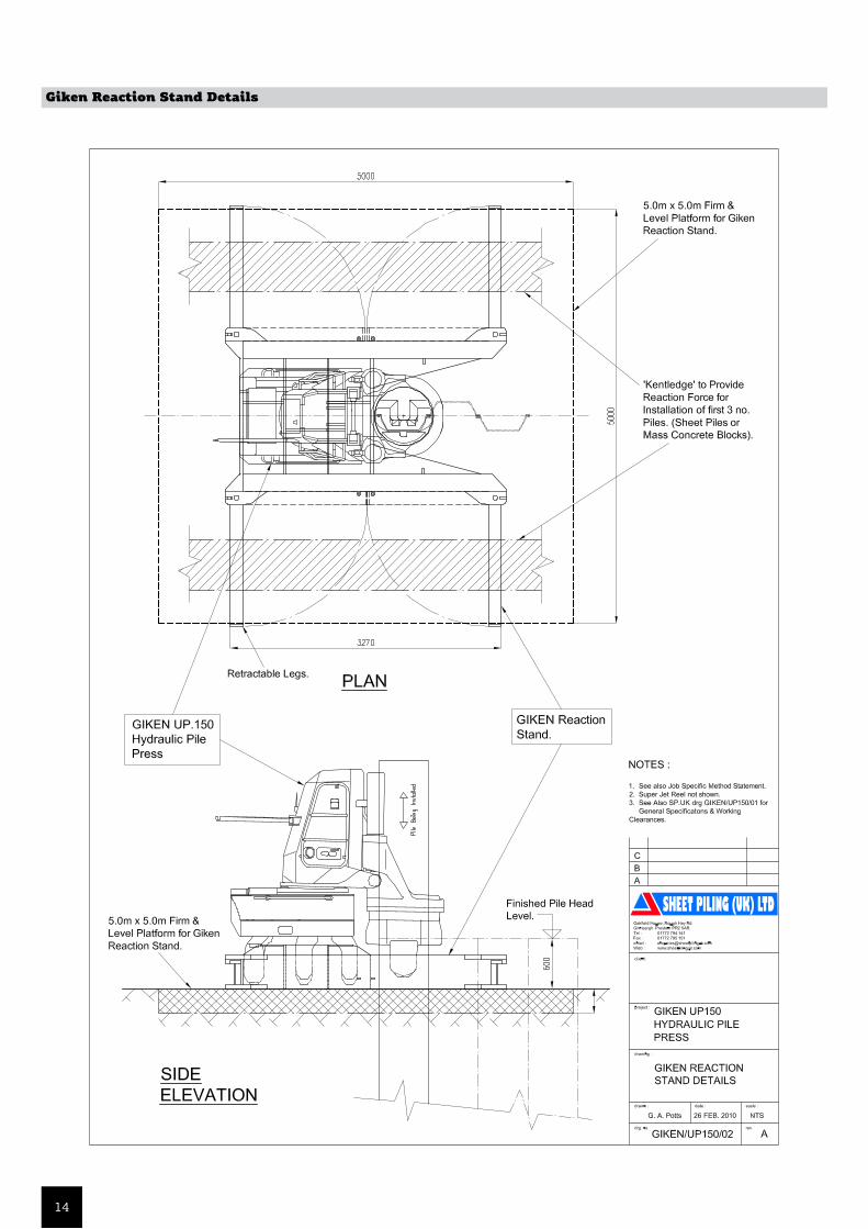
Giken Reaction Stand Details
14

General Details and Clearances
15

STEE
L SH
EET
PILE
S
RETA
ININ
G W
ALL
SV
INYL
PIL
ING
CORN
ER P
ILES
COFF
ERDA
MS
PERM
AN
ENT
BASE
MEN
TS
STEE
L BE
ARI
NG
FOU
NDA
TIO
NS
VIB
RATO
RY P
ILIN
G
TEM
PORA
RY S
HEE
T PI
LIN
GM
ARI
NE
WO
RKS
COM
POSI
TE P
ILES
GRO
UN
D A
NCH
ORS
VIB
RATI
ON
FRE
E PI
LIN
G
JET
FILT
ER W
EEP
HO
LES
STEE
L SH
EET
PILE
S
RETA
ININ
G W
ALL
SV
INYL
PIL
ING
CORN
ER P
ILES
COFF
ERDA
MS
PERM
AN
ENT
BASE
MEN
TS
STEE
L BE
ARI
NG
FOU
NDA
TIO
NS
VIB
RATO
RY P
ILIN
G
TEM
PORA
RY S
HEE
T PI
LIN
GM
ARI
NE
WO
RKS
COM
POSI
TE P
ILES
GRO
UN
D A
NCH
ORS
VIB
RATI
ON
FRE
E PI
LIN
G
JET
FILT
ER W
EEP
HO
LES
STEE
L SH
EET
PILE
S
RETA
ININ
G W
ALL
SV
INYL
PIL
ING
CORN
ER P
ILES
COFF
ERDA
MS
PERM
AN
ENT
BASE
MEN
TS
STEE
L BE
ARI
NG
FOU
NDA
TIO
NS
VIB
RATO
RY P
ILIN
G
TEM
PORA
RY S
HEE
T PI
LIN
GM
ARI
NE
WO
RKS
COM
POSI
TE P
ILES
GRO
UN
D A
NCH
ORS
VIB
RATI
ON
FRE
E PI
LIN
G
JET
FILT
ER W
EEP
HO
LES
STEE
L SH
EET
PILE
S
RETA
ININ
G W
ALL
SV
INYL
PIL
ING
CORN
ER P
ILES
COFF
ERDA
MS
PERM
AN
ENT
BASE
MEN
TS
STEE
L BE
ARI
NG
FOU
NDA
TIO
NS
VIB
RATO
RY P
ILIN
G
TEM
PORA
RY S
HEE
T PI
LIN
GM
ARI
NE
WO
RKS
COM
POSI
TE P
ILES
GRO
UN
D A
NCH
ORS
VIB
RATI
ON
FRE
E PI
LIN
G
JET
FILT
ER W
EEP
HO
LES
STEE
L SH
EET
PILE
S
RETA
ININ
G W
ALL
SV
INYL
PIL
ING
CORN
ER P
ILES
COFF
ERDA
MS
PERM
AN
ENT
BASE
MEN
TS
STEE
L BE
ARI
NG
FOU
NDA
TIO
NS
VIB
RATO
RY P
ILIN
G
TEM
PORA
RY S
HEE
T PI
LIN
GM
ARI
NE
WO
RKS
COM
POSI
TE P
ILES
GRO
UN
D A
NCH
ORS
VIB
RATI
ON
FRE
E PI
LIN
G
JET
FILT
ER W
EEP
HO
LES
AddressOakfield House
Rough Hey RoadGrimsargh
Preston Lancashire
PR2 5ARUnited Kingdom
Telephone+44 (0)1772 79 41 41
Facsimile+44 (0)1772 79 51 51
Websitewww.sheetpilinguk.com