pine mountain publication
TRANSCRIPT
Micro-Friction Stir Welding of Aluminum Alloys:Process Characterization and Optimization of Parameters
Scott Gordon,1Stephen Liu1
1CSM-CWJCR, Golden, Colorado, U.S.A.Alex Landau2
2Ben Gurion University,Beer Sheva, Israel
Abstract
Friction stir welding (FSW) of similar and dissimilar thin–gauge aluminum alloys was investigated. A variety of tools were designed to produce sound welds . The principal welding parameters: tool geometry, rotational speed, linear velocity and temperature were monitored for a variety of plate thicknesses. An attempt to gain further knowledge in the effects of welding parameters and tool geometry on dissimilar aluminum alloy welds had been carried out on plates of thickness less then one millimeter.Metallographic analysis of the dissimilar metal micro-friction stirred welds (FSW) revealed a slightly different nugget morphology as compared to the well established FSW. Scanning electron microscopy (SEM) and energy dispersive spectroscopy (EDS) were used to examine the morphology and determine the chemical composition of the welds, by monitoring the Cu and Mg distribution in the dissimilar alloy welds. Defect-free welds with minimal softening in the adjacent thermal mechanically-affected zone (TMAZ) and heat-affected zone (HAZ) were obtained.
1.Introduction
Since its invention in 1991 at The Welding Institute (Thomas et al. 1991), friction stir welding (FSW) has undergone significant development and gained great acceptance. FSW has become commonly used for joining low melting temperature alloys such as aluminum, although ongoing research on welding iron, Inconel, and NiAl alloys has been reported (Nandan et al, 2007, Sato et al. 2008, Fuller et al 2007). This process is particularly suitable for joining dissimilar materials (Steuwer et al. 2006), precipitation hardened and metal matrix materials that would otherwise be considered unweldable using conventional welding methods (Marzoli et al. 2006). The solid-state welding process has now been implemented into the aerospace, rail, shipbuilding, and automotive industries (Smith et al.).Contact between the material being welded and the spinning shoulder on the tool generates heat. The localized heating of the shoulder allows for the material that is both in contact and in close proximity with the pin to be deformed and transported around the pin (Mishra, Ma 2005). There are two main heat sources intrinsic to FSW. First, there is friction from the contact between the tool and the base material. Second, temperature of the base metal also rises as a result of the deformation around the tool. Unlike conventional
arc welding processes, the heat generation cannot be considered as axisymmetric. Consideration of both the rotational and translational velocities leads to the definition of the retreating side (RS) and advancing side (AS) in a weld. (Elangovan 2007). The AS has resultant vectors from the tool rotation and advancement of the material that point in opposite directions, while on the retreating side they point in the same direction. As expected, each side experiences a different thermal experience. There are several process variables that affect the weld nugget and bead formation in FSW. Besides tool geometry, rotational speed (ω), travel speed (υ), and pressure (P) are the three other parameters that have the greatest effects on welding. Several researchers (Colegrove, Shercliff 2005, Nandan et al. 2007, Vilac et al. 2005, Zhang et al. 2007) have attempted to model how these variables affect welding. Wei suggested a simplified equation to describe the process heat input as follows.
(1)
Where e is the energy input, P is pressure, R is the rotational speed, V is the travel speed, and C is a constant dependent on the tool geometry and the friction coefficient between the tool and the material being welded (Wei et al. 2007). Equation 1 is comparable to the heat input equation for arc welding,
(2)
where V is voltage, I is current, and s is the travel speed. The finished welds have different regions that can be characterized as function of the different processing conditions during welding. They are the stir zone (SZ), the thermal mechanically-affected zone (TMAZ), the heat-affected zone (HAZ), and the base material (BM). Examples of these regions are shown in Figure 1.1. The stir zone is characterized by the most mechanical working caused by sticking and direct contact with the pin. The TMAZ experiences both thermal and mechanical effects, i.e. heating of the material and plastic deformation caused by the tool. Yet, the tool has no direct contact with this region. The heat-affected zone is the region in which process heat caused microstructural changes such as grain coarsening and formation and dissolution of precipitates. Mechanical properties may be deteriorated in this region.
Figure 1.1. Transverse cross-section of FSW on 1 mm-thick AA2024 plate showing the different regions of the weld.

As shown by Zhang et al, the material flow around the pin is not symmetrical. The flow behavior changes around the pin as the travel speed and rotational speed change (Zhang et at. 2007). Material flow during FSW has been studied using pre-embedded tungsten markers that can later be observed using radiographic methods (Schneider et al. 2006). Realizing that several velocity fields exist during welding, their combined input would cause the material to not only flow from the front of the pin to the rear, but also with a vertical displacement component. At higher temperatures the material in close proximity to the pin becomes more plasticized; when this material is swept around the pin to a colder region, it solidifies1. While this hot material yields, the adjacent (bulk) material is not strained. When both the bulk material and the high temperature material cool down, the material next to the pin then becomes sticky attempting to drag along with it the bulk material to result in a period of high strain. Since new material is continuously entering into the stir zone, heat generation is not always constant, resulting in asymmetric flow. The hot-cold-hot cycle repeats, giving way to the oscillating stir zone.Tool shoulder-to-pin diameter ratios play an important role in SZ development (Williamson et al. 2006). Tools with shoulder-to-pin diameter ratios close to 1 (one) do not produce a TMAZ and do not adequately preheat and soften the material before the tool advances. Tools with very large shoulder-to-pin diameter ratios may preheat and soften too much the material, resulting in the material not sticking to the pin. As an empirical suggestion, tools with shoulder-to-pin diameter ratios close to 2 or 3 are more favorable than those outside this range to induce plastic flow around the pin, provided there is sufficient heat input. Without sufficient heat input, inadequate plastic flow occurs with the formation of voids. When the heat generated by the shoulder is low, the contribution of heat from plastic strain is large. On the other hand, when the shoulder begins to produce more heat, the contribution from plastic strain then decreases (Heurtier et al. 2006). For example, when operating at high rotational speeds the material around the pin softens due to the higher heat input from the shoulder but the TMAZ decreases in thickness. As result, the weld nugget will have similar dimensions to those of the pin. In contrast, when operating at the lower end of the heat input scale, i.e. lower rotational speeds, the TMAZ is comparatively large but the material may not be fluid enough to be swept around the pin. The FSW flow field can be divided into three regions. (1) Near the crown surface of the weld, material from the retreating side is dragged across the weld centerline and deposited on the advancing side. (2) In the majority of the welds (except in the case of welding thin sheets, wherein the first region mentioned may contain
1 This term does not refer to the classic solidification of a liquid. Rather, this is the hardening of a plasticized, soft material that flows in the same manner as a highly viscous fluid under the influence of a rotating pin,
the greater part of the whole thickness), all of the material intersecting the pin travels around the retreating side and is deposited behind the tool, being transported backward from its original position by no more than one pin diameter.(3) Near the bottom of the pin, at the weld root, some material is ‘‘stirred’’ in a pattern similar to that which is observed under the shoulder, but on a smaller scale. The flow in this region is complicated due to constraint from the backing plate. The most important material flow is that described in number two from the list above (Reynolds 2008).There is a point on the advancing side where the material flow velocity becomes stagnant leading to a pile up of the material. As the bottom of the pin is approached these opposing velocity fields become more evident as compared to the mid or top section of the weld. The material flow close to the top of the pin or bottom of the shoulder has the highest velocity with the least amount of opposition due to the increased amount of heat that is generated closer to the shoulder (Colegrove and Shercliff, 2005).Defects originate as a result of improper flow or geometry. Geometric defects occur when either the tool geometry is not sufficient to penetrate the entire thickness of the material or the seam is not properly tracked by the tool during welding. It is believed that the optimum welding parameters provide conditions where there is balance between sticking and slipping of the material around the pin. The material produces almost a whipping flow. Flow-related defects occur when welding is conducted outside the proper processing window, i.e. welding conditions that are either too hot or too cold. Under cold processing conditions with slip, the resulting defect is either a surface defect or wormhole. The loss of material on the retreating side of the stir zone (below the pin) or the retreating side close to the shoulder surface results in a wormhole, lack of surface fill or volumetric defect on the AS. The appearance of these defects is a direct result of the lifting of the sheet, or sheet separation, and can be observed as a flash or raised crown, depending on the amount of forging force. During the welding of sheet material in a lap configuration under hot conditions, the material in the TMAZ on the retreating side is forced upwards causing the thinning of sheets. A critical total mass of material must move from the front of the tool to the rear of the tool through the extrusion zone to maintain mass balance and prevent void formations (Arbegast 2008).The relative velocity between the work piece and the tool increases as the distance from the tool increases. More heat is generated further away from the center of the shoulder. The same can be said about the heat generation rate below the pin. The non-uniform heating is a result of the difference in relative velocities along different angular locations on the pin surface. Local differences in heat generation do not lead to large variations in localized temperatures because of the rapid recirculation of plasticized material along the pin surface (Nandan et al. 2007).
2. Experimental Procedure and Setup
2

Section 2 describes the experimental setup and procedures for this research work. Machining and heat treatment of the tools, design and building of the fixture, friction stir welding of the specimens, and monitoring of the temperature of the welds are all discussed in detail. 2.1 ToolsThe tools were made using an H-13 tool steel and heat treated to 49 HRC. Several different tools that have proportional shoulder-to-pin diameter ratios of 3:1 and 5:1 were produced. Furthermore, the tools were also scaled down from a 18 mm shoulder and 6 mm pin to a 3 mm shoulder and 1 mm pin. In this report, the tools are identified using the following designation: pin length-shoulder diameter-pin diameter, with dimensions given in mm. The tools produced in this work were 3-9-3, 2-6-2, 0.75-6-2, 1-5-1, and 1-3-1. 2.2 Base PlatesAA2024-T3 (Al-Cu-Mg) and AA5083-O (Al-Mg-Mn-Cr) alloys were used for the welding experiments. The plates had width-by-length dimensions of approximately 100 x 125mm. 2.3 Welding FixturesSeveral welding fixtures were built in this work. The one used in most experiments described in this work featured spring loaded thermocouples embedded in a stainless steel substrate.
Figure 2.4. Welding fixture holding aluminum plate before welding.
2.4 Operating Variables: Tool, Load, Rotational Speed, and Travel SpeedFor tool rotation and travel, a 2 HP Bridgeport vertical mill with an adjustable speed traveling bed was used. 2.5 Instrumentation An IO Tech Personal DAQ/55 system with software installed on a Dell Inspiron 1150 Laptop was used to record the temperature evolution during welding. 2.6 Welding Procedure Two groups of tests were performed. These are the plunge test (without travel) and the welding tests (with travel). Plunge TestBefore any bead-on-plate or butt welds could begin, a plunge test was done to acquire temperature data for each tool. The tool was preset to a plunge depth of 0.125mm above the bottom of the shoulder and the rotational speed was varied. After verifying the maximum temperature for each tool and rotational speed, the tool with a rotational speed that reached 350°C was chosen for welding. The tools with the 9 mm, 6
mm, and 5 mm shoulder were able to produce the 350°C above 1850 rpm while the tool with the 3 mm shoulder was not. Starting with a higher heat input was thought to be logical to help avoid breaking the tool under the higher stresses during lower heat input welding. Welding Welding was done in both the bead-on-plate and butt configurations with rotational speed between 1800 and 4100 rpm. Travel speed varied between 150 and 250 mm/min. A specific tool was selected for each plate thickness and the desired depth of penetration. 2.7 Sample Preparation and CharacterizationThe welds were cut transverse to the welding direction in a region that did not display visual surface defects. The samples were then mounted in Bakelite® and ground from 240 to 600 grit. Polishing began with a 6 μm diamond suspension and ended with 1 μm Al2O3 slurry. For a final polish of 0.05μm, colloidal silica was used.Several different etching techniques were used to reveal different features within the weld. A modified Keller’s reagent was used for both the AA2024 and the AA5083 alloy. 2.8 MicroscopyOptical microscopy examination was performed using an Olympus PMG-3 microscope with both normal and polarized light. Pax-It imaging software was used to capture the images. Light micrographs were taken from the different zones of the weld at magnifications between 50X and 1000X. The 50X micrographs were taken of the complete welds to include the base material, HAZ, and TMAZ.2.9 Hardness Measurements Hardness measurements were taken at the center of the welds in both transverse and vertical directions. Vickers hardness measurements were made using a 50-gmf load and a dwell time of 5 seconds. Indentations were made every 0.25 mm, with starting and ending approximately 4 mm before and after the center of the weld in the horizontal direction, and every 0.125 mm in the vertical direction, starting and ending 0.125 mm from the top and bottom of the weld. Note when delineated on hardness plots, the determination or inference of the HAZ and TMAZ boundaries is subjective because the procedure was based on subtle changes in the different microstructures.
3. Results and Discussion
To determine the specific effects of each of the variables, i.e. tool geometry, rotational speed, travel speed, plate thickness, and alloy type, the results of several tests will be discussed in the following. 3.1 Plunge TestsPlunge tests were done on AA5083 plates ranging in thickness between 1 and 3 mm to gather temperature data for the different tools. Rotational speed was increased from 720 to 4100 rpm at increments of 500 rpm. In general, the maximum temperatures increased with increasing rotational speed. For tools with the same diameter pins, shoulder size proved to be a more important variable. Larger shoulder diameters resulted in
3

higher temperatures and faster heating rates. Again, the rate at which the temperature increased was also greater. For the 1 mm pin with 3 mm shoulder and a rotational speed of 4100 rpm, the maximum temperature reached was around 300oC. The 3 mm pin with 9 mm shoulder required only 1850 rpm to heat the plate up to almost 400oC. Based on the temperatures recorded in the plunge tests, 350°C was chosen as the target temperature for welding the aluminum alloys in the present experiments. This temperature was selected because dynamic recrystallization usually occurs at temperatures greater than half the melting temperature of the alloy. This temperature was also selected to reduce the chances of breaking the tool during travel. A tool with a 9 mm shoulder and 3 mm pin could reach 350oC at 1300 rpm. For the 6 mm shoulder and 2 mm pin, 1850 rpm was necessary, and for the 5 mm shoulder with 1 mm pin, 2400 rpm would be required. In contrast, the 1 mm pin with 3 mm shoulder was not able to heat the plate up to 350oC. Even at 4100 rpm, the temperature reached only just over 300°C. 3.2 Weld TestsSeveral bead-on-plate and butt welds were made on AA5083, AA2024, AA7075, and AA6061 coupons of various thicknesses. Both similar and dissimilar alloy joint configurations were used. Again, temperature and hardness data were collected. Light microscopy was used to examine the weld microstructures. Bead-on-plate weld - 2.3 mm Thick AA5083-O Plate Bead-on-plate welds were produced on a 2.3 mm thick AA5083-O plate with the 2-6-2 tool. Note that 2-6-2 refers to pin length-shoulder diameter-pin diameter in millimeters. The rotational speed was 1850 rpm and the travel speed was 150 mm/min. The maximum temperature reached during the plunge phase was 285°C at the first thermocouple and fell to 240°C by the time the tool reached the last thermocouple, located 90 mm from the start. The top surface of the beginning portion of the weld exhibited semi-rough swirl marks (or surface ripples). The underside of the weld displayed a round protrusion at the start of the weld because of the initial plunging. Once the weld travel began, the extrusion decreased in size, eventually to the width of the pin. However, the impression remains clearly noticeable. Formed during the plunge phase, the protrusion in the beginning of the weld is smaller than the diameter of the shoulder because the tool and plate were not completely heated to a steady-state temperature. Within this transient stage the material under the tool may be overheated due to relatively long initial dwell time. This behavior extended along the length of the weld for approximately 25 mm until the protrusion narrowed to the width of the pin. At the location where the protrusion (ridge) subsided on the bottom, a flash was produced on the retreating side of the top surface. A schematic drawing, Figure 3.1, is provided to show the measurement of the ridge. Figure 3.2 is a 50X magnification optical micrograph of the transverse cross-section of the weld. The dotted lines delineate the different zones of the weld, which are clearly visible. The upper two-thirds of the weld cross-section had a V-shaped morphology and the bottom part was straight with near-
vertical interfaces. The average grain size in the base metal was approximately 50 µm in length by 10 μm in width. The grains in the stir zone range from less than 1 μm in the beginning of the weld on the advancing side to the 50 μm size in the base material on the retreating side.
Figure 3.1. A schematic drawing illustrating the measurement of the size of the ridge.
Figure 3.2. Optical micrograph of AA5083 alloy taken at 50X magnification.
The area in Figure 3.2 delineated by a circle in the lower portion on the advancing side of the stir zone shows a small tunnel defect. An internal swirl or band-like formation indicated in Figure 3.3 can be seen adjacent to the defect in the stir zone. The swirl was a vortex within the stir zone caused by the material flow around the pin, from the top and then pushed downward by the pin, shoulder and threads, and from the bottom because of the constraint of the backing. The material would then meet at a point close to “X” indicated on the photomicrograph. This point is also furthest away from the shoulder in the vertical direction and experiences the lowest temperature. At this point, the material has traveled at least one full revolution from the starting point. If there is insufficient plasticity because of the low temperature, material flow can be limited resulting in non-bonding defect.
4

Figure 3.3. Optical micrograph of the region adjacent to the discontinuity for a bead-on plate weld using 2.3-mm AA5083 plate taken at 50X magnification.The advancing side of the weld displayed maximum hardness values of around 95 HV while the hardness at the retreating side was equivalent to that of the base material, at approximately 90 HV. Even though noticeable, the hardness in the HAZ was not drastically different from that of the base material, higher only by about 5 to 10%. The hardness just below the shoulder and around the base of the pin had higher values than the center of the weld. Since this is not a full-penetration weld the hardness values of the material directly below the stir zone and of the un-stirred base material fell dramatically to well below that of the original base materials. Bead-on-plate weld - 1.3 mm Thick AA5083-O PlateDecrease in Plate Thickness, Increase in Rotational Speed and Travel Speed Bead-on-plate weld was performed on 1.3-mm thick AA5083-O plate with the 1-5-1 tool at 2400 rpm and 200 mm/min. Different from that observed in the plunge test, the underside of the weld displayed no sign of abnormality. The swirl marks or surface ripples caused by the shoulder appeared smooth and shiny along the length of the weld, except for the last 20 mm of the weld where the surface became rough. A large flash extended the length of the weld until the rough surface began. An indentation caused by the tool shoulder of approximately 0.15 to 0.2 mm was observed on the surface of the weld. The indentation appeared to decrease at the end of the weld when the roughness started. A transverse cross-sectional micrograph taken at 50X magnification is shown in Figure 3.4. The weld exhibited a stir zone that had a wide “V” morphology starting from the edge of the shoulder and continuing essentially in a straight line to the bottom of the pin. The different zones are approximately delineated by the line traces drawn according to microstructural examination. On the advancing side and around approximately the bottom 20 percent of the stir zone, the change in slope of the SZ/TMAZ interface provides some indications of the indentation of the pin. The grains in the stir zone measured around 1 μm in diameter on the advancing side, as shown in Figure 3.5, which is an enlarged view of the white dot in Figure 3.4. The cross-sectional view in Figure 3.4 shows that this weld experienced a balanced heating and stirring.
Figure 3.4. Transverse cross-section of FSW on 1.3-mm thick AA5083 plate using the 1-5-1 tool.
Plate-to-Plate Butt Welding – 1.5-mm Thick AA2024-T3 PlateTwo sets of welds were performed on 1.5 mm thick AA2024-T3 plates using the 0.75-6-2 tool at 2400 rpm and 200 mm/min and also at 1850 rpm and 150 mm/min. A tool with a larger shoulder and wider pin was chosen for these welds to accommodate for possible joint and setup mismatch of the plates. The pin length was reduced to 0.75 mm to produce a full penetration weld on a 1 mm thick material, but a partial penetration in thicker sheets. The 1.5 mm plate was chosen to observe the behavior of the stir zone below the pin because the effects were not as easily observed on the thinner welds. Two issues arise when a tool is too long: first, a defect will form on the bottom side of the weld when the pin is too close to the backing; second, the welded plates tend to become welded to the backing. This behavior is analogous to the melt-through during fusion welding processes.
Figure 3.5. Optical micrograph of the advancing side stir zone in bead-on-plate weld on 1.3-mm thick AA5083 plate taken at 200X magnification. Welding Parameters: 2400 rpm and 200 mm/minAt a rotational speed of 2400 rpm and travel speed of 200 mm/min, there was a large flash that extended nearly the entire length of the weld and a deformed ridge formed on the underside. As the flash increased or decreased in size so did the ridge on the underside. The surface appeared to be defect free by visual inspection. The swirl marks caused by the shoulder appeared to be smooth and shiny along the entire length of the weld.
5
Band or wave formation
Tunnel Defect X

Figure 3.6. Transverse cross-section of FSW on 1.5-mm thick AA2024 plate using the 0.75-6-2 tool. Keller’s reagent was used to etch the surface. 50X magnification.
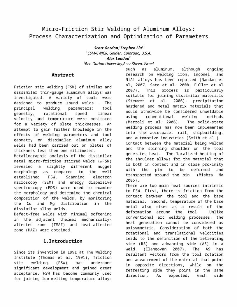
The stir zone appears to have a wedge or “V” shape as shown in Figure 3.6. The grains in the advancing side of the stir zone and directly below the shoulder were approximately 1 μm in size and progressively became larger, up to the 30 to 50 μm grain size when approaching the retreating side. The AA2024 base material had approximately 30 to 50 μm elongated grains with 2-10 μm constituent particles on the grain boundaries as shown in Figure 3.7.
Figure 3.7. Typical microstructure of the AA2024 base material, 1000X magnification. Keller’s reagent was used to etch the surface.
Figure 3.8. Advancing side TMAZ and SZ, 500X magnification. The dotted line marks the interface.
Figure 3.9. Rounded constituent particles surrounded by a matrix of 1-5 μm grain in the advancing side of the SZ. 500X magnification.
Figure 3.8 shows that the interface of the SZ and the TMAZ was not a definite boundary. Instead, the greater deformation in the SZ resulted in grain refinement that exhibited different etching behavior which helped to delineate the SZ-TMAZ transition. Note that this transition was gradual and the demarcation of the boundary could be subjective. The constituent particles within the stir zone were considerably smaller near the advancing side interface and increased in size through the retreating side as shown in Figure 3.9. The dark region at the bottom of the stir zone in Figure 3.6 consists of two regions. The upper half of the region was formed because of direct contact with the rotating pin and stirring of the material. The lower half of the region was caused by the sticking and flowing of the material below the pin. The boundary between the dark region and the light region in the stir zone in Figure 3.6 correlates well with the decrease in hardness at approximately 0.8 mm from the bottom of the weld in Figure 3.10. This area of decreased hardness was caused by the reentrant material flow.
Figure 3.10. Microhardness plot along the centerline of the weld on 1.5 mm AA2024 plate welded with 0.75-6-2 tool at 2400 rpm and 200 mm/min. The top of the weld is on the right-hand side of the plot. Indention was made at 50-gmf for 5 seconds and taken from the center line of the weld.
6
SZ
TMAZ

Figure 3.11. Transverse cross-section of FSW on 1.5-mm thick AA2024 plate using the 0.75-6-2 tool.
Welding Parameters: 1850 rpm and 150 mm/minThe weld made using 1850 rpm and 150 mm/min was not defect free. A large surface opening along the advancing side extended well over half the length of the weld. On the retreating side there was a large flash on the top and a large ridge on the bottom similar to the one shown in Figure 3.1. A dark void in the stir zone was also found as illustrated in Figure 3.11. The large void on the advancing side of the weld is actually a tunnel pore. The transverse cross-section of this weld exhibited a different morphology than that of the weld made using tool rotational speed of 2400 rpm and travel speed of 200 mm/min. The weld nugget did not have the same wedge or “V” appearance as shown in Figure 3.6. The welds produced with lower restraint had an interface profile on the advancing side similar to that of the vertical profile of the pin. Without sufficient restraint on the retreating side the material was allowed to be pushed to the retreating side caused by an irregular mass flow balance. Observed under light microscopy, the nugget had a similar grain size and constituent particle distributions as in the other welds.
Figure 3.12. Longitudinal microhardness plot for the weld on 1.5-mm thick AA2024 plate welded with 0.75-6-2 tool at 1850 rpm and 150 mm/min. Indention was made at 50 gmf for 5 seconds. Hardness data was taken laterally from the mid section of the material slightly above the defect on the advancing side.
The transverse hardness profiles do not show a smooth and constant profile as shown in Figure 3.12. The relatively large variations in hardness were caused by a lack of heat input. When there is insufficient heat input a cavity usually forms on the advancing side behind the pin and close to the base material. During welding using parameters that border on low heat input values, the cavity expands and contracts as the material is swept around the pin. When there is not enough material to flow around the pin, the cavity expands and a void
forms. When there is sufficient material flow around the pin, the back up of material in the cavity causes a compressive force resulting in further plastic deformation of the base material. These periodic back up of material, pressure build up and release in the weld nugget causes the fluctuations in the hardness readings. The hardness values in the HAZ on both the advancing and retreating side in Figure 3.12 vary in a cyclic manner. Bead-on-Plate and Butt Weld – 1 mm Thick AA2024-T3 PlateBead-on-plate and butt welds were produced on 1-mm thick AA2024-T3 plate using the 0.75-6-2 tool at 2400 rpm and 200 mm/min. Both welds had a significant number of surface defects that extended almost the entire length of the weld. Decreasing the material thickness caused several problems. The first of these problems was the resistance of the material to deformation during stirring. The thinner materials seemed to be more easily lifted away from the backing than the thicker plates due to the extrusion of the stir zone material towards the bottom surface. The bottom-side ridge was formed along with the retreating side plate being pushed upward. As a result a defect formed that was visible on the top surface of the weld in conjunction with the ridge as shown in Figures 3.13a and 3.13b. A fixture that holds the plates at a distance closer to the tool shoulder would reduce the effects of this problem.
Bead-on-Plate Weld - 1 mm Thick AA2024 PlateFor the BOP weld, the cross-sectional area as shown in Figure 3.14 appeared to be similar in morphology to that of the 1.5 mm thick AA2024 plate weld shown in Figure 3.6. The nugget showed no internal defects at this cross-section location. Surface defects were observed only at the start and end of the weld.
Figures 3. 13a. & 3.13b. Top and bottom surface of the 1.0-mm AA2024 BOP plate weld. Figure 3.13a displays an abnormally rough surface at the beginning of the weld which also corresponds to the material being pushed up from the bottom.
Figure 3.14. Transverse cross-section of FSW on 1.0-mm thick AA2024 plate BOP weld using 0.75-6-2 tool.
7
Figure 3.18. Longitudinal microhardness plot for the weld on 1.5-mm thick AA2024 plate
welded with 0.75-6-2 tool at 1850 rpm and 150 mm/min. Indention was made at 50 gmf for 5
seconds. Hardness data was taken laterally from the mid section of the material slightly
above the defect on the advancing side.
a. b.
RS
Ridge RS
AS

Even though only slight changes, the hardness data shows a decreasing trend from the advancing side to the retreating side of the stir zone, Figures 3.15 and 3.16. The variations in hardness in the TMAZ and HAZ of this weld were less than those of the welds completed with lower heat input parameters, e.g. 1.5-mm thick plate at 1850 RPM and 150 mm/min. As the heat input is greater, these hardness variations decrease to a smooth line (see arrows in Figures 3.15 and 3.16). This decrease in hardness scatter is caused by the more uniform stir and flow of the material around the pin, from the advancing side to the retreating side, along with smaller fluctuations in pressure associated with the material flow around the pin. The plasticized material in the TMAZ acts as buffer absorbing the shock of the between the pin and the unaffected base material since this latter behaves more like a rigid body. When comparing the advancing side hardness data of the BOP weld on 1 mm thick AA2024 plate, Figure 3.15, to the 1.5 mm thick AA2024 plate-to-plate weld hardness data, Figure 3.12, the plate-to-plate hardness profile is much smoother. The heat input of this weld was greater for two reasons: first, the material thickness is less, and second, the rotational speed was faster. By changing these parameters, the extent of stirring was increased, thus causing a buffer layer of plasticized material around the pin to absorb a majority of the shock. Since the stirring in this weld was greater than that in the 1.5-mm thick AA2024 plate weld, Figure 3.16 shows a region just above the bottom of pin with a deviation in hardness. With a higher material velocity along with a faster cooling rate, dislocations have less time to become mobile resulting in a region of increased hardness. In friction stir welding, the heat extraction of a plate-to-plate weld differs considerably from that experienced by a bead-on-plate weld. The bead-on-plate welds are expected to have a more uniform heat extraction whereas the plate-to-plate welds tend to extract heat differently in the two coupons. Different temperature gradients will be established on each side of the joint until the stirring or heat input is high enough to substantially decrease the differences in thermal conditions in the two coupons.
Figure 3.15. Longitudinal microhardness profile for 1 mm AA2024 BOP weld welded with 0.75-6-2 tool at 2400 rpm and 200 mm/min. Indention was made at 50 gmf for 5 seconds.
Figure 3.16. Vertical microhardness plot for 1 mm AA2024 welded with 0.75-6-2 tool at 2400 rpm and 200 mm/min. Indention was made at 50 gmf for 5 seconds.
Butt Weld - 1 mm Thick AA2024 PlateThe photomicrograph in Figure 3.17 shows no indications of internal defects at that cross-section (68 mm from the start of the weld). The bead morphology was similar to that of the weld on the 1.5 mm thick AA2024 plate with the welding parameters of 1850 rpm and 150 mm/min parameters as shown in Figure 3.11. This weld also exhibited a vertical interface between the stir zone and the base material.
Figure 3.17. Transverse cross-section of FSW on 1-mm thick AA2024 plate using 0.75-6-2 tool.
The hardness profile in Figure 3.18 shows a smooth curve that decreases as the stir zone is approached. This is unlike the varying hardness profile as shown in Figure 3.12. The retreating side is however a little different; for the most part there is a smooth curve except in the region close to the stir zone. Since this is a butt weld, there are individual thermal zones for each of the two coupons. There is more heat generated on the advancing side of the weld while the retreating side of the weld is slightly cooler. Although there are no large variations in hardness, there is a slight fluctuation where the material from the top portion of the weld meets the reentrant material for the bottom of the stir zone. Extracting samples from different regions within the weld and using TEM to evaluate them could help to determine what microstructural changes that cause these fluctuations in hardness, i.e. precipitant growth, dislocation density, etc.
8
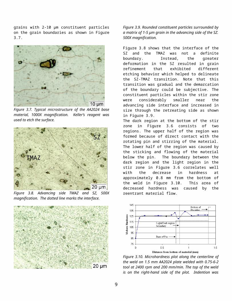
Figure 3.18. Longitudinal microhardness plot for 1mm AA2024 plate welded with 0.75-6-2 tool at 2400 rpm and 200 mm/min. Indention was made at 50-gmf for 5 seconds. Data points were taken horizontally from the mid section of the material.
Dissimilar Metal WeldingButt Weld – 1 mm Thick AA2024 Plate to 1.5 mm Thick AA5083 PlateThe dissimilar metal, dissimilar thickness weld was completed with the 0.75-6-2 tool at 2400 rpm and 200 mm/min. The AA2024 plate was on the advancing side of the weld. A large flash, approximately 1/3 the diameter of the tool, formed along the entire length of the weld and through-thickness surface defects were observed over 50% of the weld length. During welding, the pin of the tool almost came into contact with the surface of the backing substrate. There were regions on the bottom side of the weld where the pin had protruded through, leaving a void because the material had lifted away. A transverse cross-sectional micrograph was taken at 32 mm from the start of the weld as shown in Figure 3.19. Along the advancing side there was a tunneling defect observed. This cross-section was taken between two linear surface defects that were visually identified. Since the specimen was taken between these two surface defects it is reasonable to believe that the tunnel defect migrated from the top surface to an internal location depending on the heat input. The restraining pressure was not sufficient for the mass flow balance to produce a sound weld. In the region where restraining pressure was adequate, the bead morphology is similar to that of the weld on 1.5 mm thick AA2024 plate with the welding parameters of 1850 rpm and 150 mm/min parameters as shown in Figure 3.11.
Figure 3.19. Transverse cross-section of FSW on 1mm AA2024 – 1.5 mm AA5083using 0.75-6-2 tool.
Several features could be easily identified within the weld. There were streaks (bands) at the interface between the AA2024 (left) plate and the AA5083 (right) plate as shown in
Figure 3.19. The material flow at the bottom and below the pin showed vortices and non-uniform stirring. The hardness profile, shown in Figure 3.20, shows a slight spike in hardness at locations close to -3 mm and 2.5 mm from the weld center. This spike correlates with the diameter of the shoulder. The increase in hardness is caused by the downward pressure of the shoulder resulting in mechanical working of the material. The decreasing trend in hardness when approaching the stir zone can be attributed to the combined heat generation from both the shoulder and the pin that promoted softening. Although there are some fluctuations in hardness within the HAZ on both the advancing and retreating side, their magnitude is relatively small. Within the stir zone there is a decrease in hardness as the retreating side is approached caused by the mixing of the harder AA2024 with the softer AA5083 material. This gradient is not abrupt suggesting possibly two reasons for this change, first, there is some mixing of the two materials; second, the differences in grain size between the advancing side and retreating side. As shown in Figure 3.21 the region close to the shoulder has lower hardness than that closer to the bottom of the pin. This observation correlates well with the SEM image, Figure 3.23, where the region with the darker shade of grey is the softer AA5083 material. The mixing of these two materials can more easily be observed in the SEM image. Not much mixing of the two materials occurred within the upper and lower regions of the stir zone, while there is a very small amount of mixing beneath the pin. EDS showed that there was not much difference in copper concentration in the copper-rich region of the stir zone and the base material. The upper region of the weld is predominantly AA5083 and the lower regions of the weld are comprised mainly of AA2024 alloy.
Figure 3.20. Longitudinal micro-hardness plot for 1 mm AA2024-1.5 mm AA5083. Indention was made at 50 gmf load for 5 seconds. Data points were taken from the mid section of the weld.
9

Figure 3.21. Vertical micro-hardness plot for 1mm AA2024-1.5mm welded toAA5083 welded with 0.75-6-2 tool at 2400 rpm and 200 mm/min. Indention was made at 50 gmf for 5 seconds.
Figure 3.22. SEM image taken at 23X. Light grey region is AA2024 and the dark grey is the AA5083. Dashed line approximately delineates the pin and shoulder.
Several more welds were produced using AA7075 and AA6061 plates. These welds were produced using the 0.6-6-2 tool at 2750 rpm as shown in Figure 3.23a and 2300 rpm, Figure 3.23b. Since the travel speed used was on the lower end, the operating window for these materials would be narrow. The beginning and end of the welds displayed some signs of surface flaws and a rough surface appearance. However, the mid section of this region appeared to be smooth and defect free. Face bending of the weld to greater than 90 degrees from flat revealed surface flaws but the midsection of the weld proved to be sound. Comparing these two welds, the coupon with the AA7075 plate on the advancing side appeared to fail slightly more than when the AA6061 was placed on the advancing side.
Figure 3.23 1 mm thick plates welded at (a) 2750 rpm, (b) 2300 rpm and 200 mm/min
Finally, 0.63 mm thick AA6061 plates were welded in a butt configuration using a 0.1-3-1 tool. Initially, several attempts were made but resulted in welds with linear surface defects along almost the entire length of the weld. An observation was made that the fit-up between the plates was not tight and there was a small, almost unnoticeable, ridge along the bottom. The gap was caused by the corner not being square because the coupons were sheared. The plates were then machined square and some additional clamping was used. The result was a weld that appeared to be defect free for a majority of the length of the coupon. Figure 3.24 is a transverse cross-section of the weld. The weld was made at 3440 rpm and 240 mm/min. An increase in travel speed would help to eliminate the defect at the end of the weld.
Figure 3.24 0.63 mm thick plates welded at 3440 rpm 240 mm/min.
4. Summary
The FSW process was able to produce sounds welds in this research program. The tool design was able to withstand the wear and temperature of the welding process. After several iterations a fixture capable of restraining the thin plates was produced. Metallographic techniques were developed specific to the dissimilar aluminum alloy welds. To produce a defect-free micro-friction stir weld, proper welding parameters consisting of the correct ratios of travel speed, rotational speed, and pressure must be used. Excessive plunge and tool overheating, compounded with an increased volume of material entering the stir zone, cause the formation of a flash and the tunnel defect. When the rotational speed is too high, the same effects can be seen. When the heat input is too low, tool breakage may occur. Several welds did not show the distinct swirl marks made from the tool shoulder. Instead, the swirls faded away into a coarse, rough surface. This behavior can be attributed to recrystallization because the recrystallization temperature is either approached or exceeded. These parameters border the high heat input parameters. As the rotational speed is further increased, the material in close proximity to the pin may become overheated. The volume of the material that is transported around the pin becomes too great for the region behind the pin to support. In conjunction with the upward flow of the high temperature material reentering the void behind the advancing side of the pin a high temperature, high pressure region is formed. The combination of high pressure and high flow velocity of the material, along with a low viscosity, promotes an upward flow resulting in the expulsion of the material from under the
10
a.
b.

shoulder and swept towards the retreating side. Conservation of material explains the appearance of the flash since materials is “lost” beneath the shoulder. The shoulder depth plays an important role; not only does it provide heat but it restricts the flow of material away from the surface. Joint configuration affects the amount of backing pressure and heat extraction. At low heat input values, the bead-on-plate as compared to the butt configuration yielded welds that had less defects and stir zones within which stirring could be observed. Slower rotational speed for the travel speed chosen would produce defect-free welds. The defects that form at the beginning of the welds can be attributed to the excessive heating during the plunge phase of the welding. A shorter dwell time should be sufficient to eliminate them. Defects formed at the end of the weld when the coupons become overheated from the excess heat during welding. Three possible solutions are proposed to eliminate these defects, first, reduce the rotational speed, second, increase the travel speed, and third, use an external cooling source, e.g. water-cooled copper blocks. The processing window for μFSW is smaller than that of FSW of thicker sections. Small variations of tool geometry, plate geometry, or process parameters will cause greater fluctuations in the process than in conventional FSW of thicker plates. Strict control of these parameters is critical for optimizing the process and producing defect-free welds.
References
[1] Arbegast, William J. A flow-partitioned deformation zone model for defect formation during friction stir welding. Scripta Materialia 58 (2008) 372–376
[2] Charit, Indrajit., Mishra, Rajiv S., Mahoney Murray W.,. Multi-sheet structures in 7475 aluminum by friction stir welding in concert with post-weld superplastic forming, Scripta Materialia 47 631–636 (2002)
[3] Colegrove, P.A., Shercliff, H.R. 3-Dimensional CDF Modelling of Flow round a threaded friction stir welding tool profile, Journal of Materials Processing Technology 169 320-327 (2005)
[4] Elangovan, K., Balasubramanian, V. Influences of pin profile and rotational speed of the tool on the formation of friction stir processing zone in AA2219 aluminium alloy, Materials Science and Engineering A xxx xxx–xxx (2007)
[5] Fuller, M.D. Swaminathan, S., Zhilyaev, A.P., McNelley, T.R. Microstructural transformations and mechanical properties of cast NiAl bronze: Effects of fusion welding and friction stir processing. Materials Science and Engineering A xxx (2007) xxx–xxx[6] Heurtier, P., Jones, M.J., Desrayaud, C., Driver, J.H., Montheillet, F., Allehaux, D. Mechanical and thermal modeling of friction stir welding, Journal of Materials processing Technology 171 348-358 (2006)
[7] Lee, W.B., Yeon, Y.M., Jung, S.B. The joint properties of dissimilar formed Al alloys by friction stir welding according to the fixed location of materials, Scripta Materialia 49 (2003) 423-428
[8] Marzoli, L.M.,. Strombeck, A.v, Dos Santos, J.F., Gambaro, C., Volpone, L.M.. Friction stir welding of an AA6061/Al2O3/20p reinforced alloy, Composites Science and Technology 66 363–371(2006)
[9] Maryaa, Manuel., Hector, Louis G., Verma, Ravi., Tong, Wei. Microstructural effects of AZ31 magnesium alloy on its tensile deformation and failure behaviors, Materials Science and Engineering A 418 341–356 (2006)
[10] Mishra, R.S., Ma, Z.Y., Friction Stir welding and Processing, Materials Science and Engineering R50 1-78 (2005)
[11] Nandan, R., Roy, G.G., Lienert, T.J., Debroy, T. Three-dimensional heat and material flow during friction stir welding of mild steel. Acta Materialia 55 883–895 (2007) [12] Sato, Y.S., Arkom, P., Kokawa, H., Nelson, T.W., Steel, R.J. Effect of microstructure on properties of friction stir welded Inconel Alloy 600, Materials Science and Engineering A 477 250–258 (2008)
[13] Schneider, Judy, Beshears, Ronald, Nunes Jr, Arthur C., Interfacial sticking and slipping in the friction stir welding process, Materials Science and Engineering A 435–436 297–304 (2006)
[14] Smith, C. B., Hinrichs, J. F., Ruehl, P. C., Friction stir and friction spot welding- Lean, Mean and Green, Friction Stir Link Inc
[15] Reynolds, A.P.. Flow visualization and simulation in FSW, Scripta Materialia 58 338–342 (2008)
[16] Steuwer, A., Peel, M.J., Withers, P.J. Dissimilar friction stir welds in AA5083-AA 6082: The effect of process parameters on residual stress, Materials Science and Engineering A xxx xxx-xxx (2006)
[17] Thomas, W.M., Nicholas, E.D., Needham, J.C., Murch, M.G., Temple-Smith, P., Dawes, C.J. Friction-stir butt welding, GB Patent No. 9125978.8, International Patent No. PCT/GB92/02203, (1991)
[18] Thomas, W.M., Nicholas, E.D., Smith, S.D. in: S.K. Das, J.G. Kaufman, T.J. Lienert (Eds.), Aluminum 2001—Proceedings of the TMS 2001 Aluminum Automotive and Joining Sessions, TMS 213 (2001)
[19] Vilac, Pedro., Quintino, Lu´ısa., dos Santos, Jorge F. iSTIR—Analytical thermal model for friction stir welding,
11

Journal of Materials Processing Technology 169 452–465 (2005)
[20] Williamson, Keith M., Abdel-Salam, Tarek. A moving boundary formulation for recursive plastic heat release during friction stir welding, Journal of Materials Processing Technology 180 49–52 (2006)
[21] Wei, Shitong., Hao, Chuanyong., Chen, Jichun. Study of friction stir welding of 01420 aluminum–lithium alloy, Materials Science and Engineering A 452–453 170–177 (2007)
[22] Zhang, H.W., Zhang, Z., Chen, J.T., 3D modeling of material flow in friction stir welding under different process parameters, Journal of Materials Processing Technology 183 62–70 (2007)
12