plan
DESCRIPTION
Scalable Distributed Data Structures & High-Performance Computing Witold Litwin Fethi Bennour CERIA University Paris 9 Dauphine http://ceria.dauphine.fr/. Plan. Multicomputers for HPC What are SDDSs ? Overview of LH* Implementation under SDDS-2000 Conclusion. Multicomputers. - PowerPoint PPT PresentationTRANSCRIPT

Scalable Distributed Data Structures &
High-Performance Computing
Witold Litwin Fethi Bennour
CERIAUniversity Paris 9 Dauphine
http://ceria.dauphine.fr/

2
PlanPlan
• Multicomputers for HPC • What are SDDSs ? • Overview of LH*• Implementation under SDDS-2000• Conclusion

3
MulticomputersMulticomputers
• A collection of loosely coupled computers– Mass-produced and/or preexisting hardware
– share nothing architecture• Best for HPC because of scalability
– message passing through high-speed net (Mb/s)
• Network multicomputers– use general purpose nets & PCs
• LANs: Fast Ethernet, Token Ring, SCI, FDDI, Myrinet, ATM…
– NCSA cluster : 1024 NTs on Myrinet by the end of 1999
• Switched multicomputers– use a bus, or a switch
– IBM-SP2, Parsytec...

4
Why Multicomputers ?Why Multicomputers ?• Unbeatable price-performance ratio for HPC.
– Cheaper and more powerful than supercomputers.– especially the network multicomputers.
• Available everywhere.
• Computing power.– file size, access and processing times, throughput...
• For more pro & cons :– IBM SP2 and GPFS literature.– Tanenbaum: "Distributed Operating Systems", Prentice Hall, 1995.– NOW project (UC Berkeley).– Bill Gates at Microsoft Scalability Day, May 1997.– www.microoft.com White Papers from Business Syst. Div.– Report to the President, President’s Inf. Techn. Adv. Comm., Aug 98.

5
Client
Server
Typical Network Multicomputer

6
Why SDDSsWhy SDDSs
• Multicomputers need data structures and file systems
• Trivial extensions of traditional structures are not best
hot-spots scalability parallel queries distributed and autonomous clients distributed RAM & distance to data
For a CPU, data on a disk are as far as those at the Moon for a human (J. Gray, ACM Turing Price 1999)

7
What is an SDDS ?
Data are structuredrecords with keys objects with OIDs
more semantics than in Unix flat-file model abstraction most popular with applications parallel scans & function shipping
Data are on servers– waiting for access
Overflowing servers split into new servers– appended to the file without informing the clients
Queries come from multiple autonomous clients– Access initiators
– Not supporting synchronous updates
– Not using any centralized directory for access computations
8
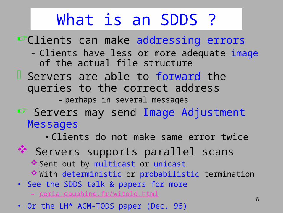
Clients can make addressing errors– Clients have less or more adequate image of the actual file
structure
Servers are able to forward the queries to the correct address
– perhaps in several messages
Servers may send Image Adjustment Messages• Clients do not make same error twice
Servers supports parallel scans Sent out by multicast or unicast With deterministic or probabilistic termination
• See the SDDS talk & papers for more – ceria.dauphine.fr/witold.html
• Or the LH* ACM-TODS paper (Dec. 96)
What is an SDDS ?

9
A server can be unavailable for access without service interruption
Data are reconstructed from other serversData and parity servers
Up to k servers can failAt parity overhead cost of about 1/k
Factor k can itself scale with the file Scalable availability SDDSs
High-Availability SDDS

10
An SDDSAn SDDS
Clients
growth through splits under inserts
Servers

11
An SDDSAn SDDS
Clients
growth through splits under inserts
Servers

12
An SDDSAn SDDS
Clients
growth through splits under inserts
Servers

13
An SDDSAn SDDS
Clients
growth through splits under inserts
Servers

14
An SDDSClient Access
Clients

15
Clients
An SDDSClient Access

16
Clients
IAM
An SDDSClient Access

17
Clients
An SDDSClient Access

18
Clients
An SDDSClient Access

19
Known SDDSsKnown SDDSs
DS
Classics

20
Known SDDSsKnown SDDSs
Hash
SDDS(1993)
LH* DDH
Breitbart & al
DS
Classics

21
Known SDDSsKnown SDDSs
Hash
SDDS(1993)
1-d tree
LH* DDH
Breitbart & al RP* Kroll & Widmayer
DS
Classics

22
Known SDDSsKnown SDDSs
Hash
SDDS(1993)
1-d tree
LH* DDH
Breitbart & al RP* Kroll & Widmayer
m-d trees
k-RP*dPi-tree
DS
Classics

23
Known SDDSsKnown SDDSs
Hash
SDDS(1993)
1-d tree
LH* DDH
Breitbart & al RP* Kroll & Widmayer
m-d trees
DS
Classics
SecurityLH*s
k-RP*dPi-tree
Nardelli-tree
LH*m, LH*g
H-Avail.

24
Known SDDSsKnown SDDSs
Hash
SDDS(1993)
1-d tree LH* DDH
Breitbart & alRP*
Kroll & WidmayerBreitbart & Vingralek
m-d trees
DS
Classics
H-Avail.
LH*m, LH*gSecurity
LH*s
k-RP*dPi-tree
Nardelli-tree
s-availabilityLH*SA
LH*RS http://192.134.119.81/SDDS-bibliograhie.html
SDLSA
Disk

25
LH* (A classic)LH* (A classic)
• Scalable distributed hash partitionning– generalizes the LH addressing schema
• variants used in Netscape products, LH-Server, Unify, Frontpage, IIS, MsExchange...
• Typical load factor 70 - 90 %• In practice, at most 2 forwarding messages
– regardless of the size of the file
• In general, 1 m/insert and 2 m/search on the average
• 4 messages in the worst case

26
LH* bucket servers LH* bucket servers
For every record c, its correct address a results from the LH addressing rulea hi(c)
if n = 0 then exit elseif a < n then a h i+1 ( c) ;end
(i, n) = the file state, known only to the LH*-coordinator
Each server a keeps only track of the function hj used to access it:
j = i or j = i+1

27
LH* clientsLH* clients
• Each client uses the LH-rule for address computation, but with the client image (i’, n’) of the file state.
• Initially, for a new client (i’, n’) = 0.

28
LH* Server Address Verification and Forwarding
LH* Server Address Verification and Forwarding
– Server a getting key c, a = m in particular, computes :
a' := hj (c) ;
if a' = a then accept c ;
else a'' := hj - 1 (c) ;
if a'' > a and a'' < a' then a' := a'' ;
send c to bucket a' ;

29
Client Image AdjustmentClient Image Adjustment
• The IAM consists of address a where the client sent c and of j (a)
if j > i' then i' := j - 1, n' := a +1 ;
if n' 2^i' then n' = 0, i' := i' +1 ;
• The rule guarantees that client image is within the file
• Provided there is no file contractions (merge)

30
LH* : file structure LH* : file structure
j = 4
0
j = 4
1
j = 3
2
j = 3
7
j = 4
8
j = 4
9
n = 2 ; i = 3
n' = 0, i' = 0 n' = 3, i' = 2 Coordinator
Client Client
servers

31
LH* : file structureLH* : file structure
j = 4
0
j = 4
1
j = 3
2
j = 3
7
j = 4
8
j = 4
9
n = 2 ; i = 3
n' = 0, i' = 0 n' = 3, i' = 2 Coordinator
Client Client
servers

32
LH* : splitLH* : split
j = 4
0
j = 4
1
j = 3
2
j = 3
7
j = 4
8
j = 4
9
n = 2 ; i = 3
n' = 0, i' = 0 n' = 3, i' = 2 Coordinator
Client Client
servers

33
LH* : splitLH* : split
j = 4
0
j = 4
1
j = 3
2
j = 3
7
j = 4
8
j = 4
9
n = 2 ; i = 3
n' = 0, i' = 0 n' = 3, i' = 2 Coordinator
Client Client
servers

34
LH* : splitLH* : split
j = 4
0
j = 4
1
j = 4
2
j = 3
7
j = 4
8
j = 4
9
n = 3 ; i = 3
n' = 0, i' = 0 n' = 3, i' = 2 Coordinator
Client Client
servers
j = 4
10

35
LH* : addressingLH* : addressing
j = 4
0
j = 4
1
j = 4
2
j = 3
7
j = 4
8
j = 4
9
n = 3 ; i = 3
n' = 0, i' = 0 n' = 3, i' = 2 Coordinateur
Client Client
servers
j = 4
10
15

36
LH* : addressingLH* : addressing
j = 4
0
j = 4
1
j = 4
2
j = 3
7
j = 4
8
j = 4
9
n = 3 ; i = 3
n' = 0, i' = 0 n' = 3, i' = 2 Coordinateur
Client Client
servers
j = 4
10
15

37
LH* : addressingLH* : addressing
j = 4
0
j = 4
1
j = 4
2
j = 3
7
j = 4
8
j = 4
9
n = 3 ; i = 3
n' = 0, i' = 3 n' = 3, i' = 2 Coordinateur
Client Client
servers
j = 4
10
15
a =7, j = 3

38
LH* : addressingLH* : addressing
j = 4
0
j = 4
1
j = 4
2
j = 3
7
j = 4
8
j = 4
9
n = 3 ; i = 3
n' = 0, i' = 0 n' = 3, i' = 2 Coordinateur
Client Client
servers
j = 4
10
9

39
LH* : addressingLH* : addressing
j = 4
0
j = 4
1
j = 4
2
j = 3
7
j = 4
8
j = 4
9
n = 3 ; i = 3
n' = 0, i' = 0 n' = 3, i' = 2 Coordinateur
Client Client
servers
j = 4
10
9
40
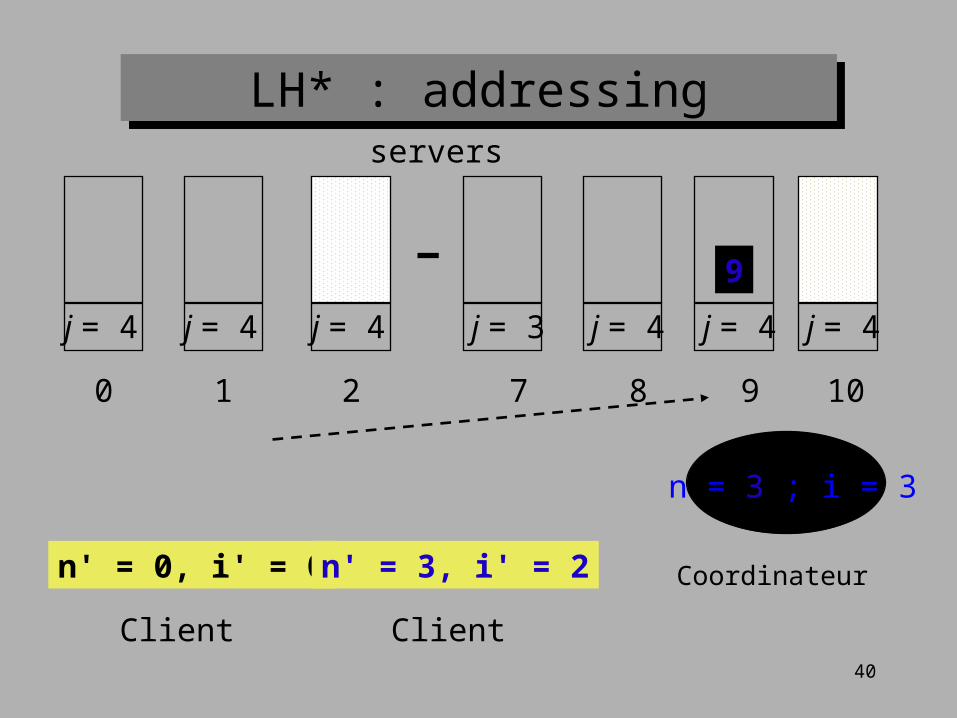
LH* : addressingLH* : addressing
j = 4
0
j = 4
1
j = 4
2
j = 3
7
j = 4
8
j = 4
9
n = 3 ; i = 3
n' = 0, i' = 0 n' = 3, i' = 2 Coordinateur
Client Client
servers
j = 4
10
9

41
LH* : addressingLH* : addressing
j = 4
0
j = 4
1
j = 4
2
j = 3
7
j = 4
8
j = 4
9
n = 3 ; i = 3
n' = 1, i' = 3 n' = 3, i' = 2 Coordinateur
Client Client
servers
j = 4
10
9
a = 9, j = 4
42
ResultResult
• The distributed file can grow to even whole Internet so that :– every insert and search are done in four
messages (IAM included)– in general an insert is done in one message
and search in two message
43
SDDS-2000Prototype Implementation of LH* and of RP* on Wintel
multicomputer
• Architecture Client/Server• TCP/IP Communication (UDP and TCP) with
Windows Sockets • Multiple threads control• Processes synchronization (mutex, critical section,
event, time_out, etc)• Queuing system• Optional Flow control for UDP messaging

44
Send Request
Receive Response
Return Response
Client Image process.
SDDS-2000 : Client Architecture
Interface : Applications - SDDS
send Request
Socket
Network
Response
Request
ReceiveResponse
file i n
..... .....
Client Image
Update
Server Address
ReceiveRequest
ReturnResponse
Id_Req Id_App ... .....
Queuing system
Request Response
Applications
Server

45
SDDS-2000 : Server Architecture
Bucket SDDS
Insertion Search Update Delete
W.Thread 1 W.Thread 4…
Request Analyse
Queuing system
Listen Thread
Socket
Client
Network
client Request
Response
Response
Listen Thread
Queuing system
Work Thread
Local process
Forward
Response

46
LH*LH : RAM buckets
.
.
.
LH bucket
LH* bucket
A recorddynamic array
04
data 1 2 data 2 6 dataX 8 data3 -1 dataY -1
0 1 2 3 4 5 6 7 8 9

47
Measuring conditions
LAN of 4 computers interconnected by a 100 Mb/s Ethernet
F.S : Fast Server : Pentium II 350 MHz & 128 Mo RAM F.C : Fast Client : Pentium II 350 MHz & 128 Mo RAM S.C : Slow Client : Pentium I 90 Mhz & 48 Mo RAM S.S : Slow Server : Pentium I 90 Mhz & 48 Mo RAM The measurements result from 10.000 records & more. UDP Protocol for insertions and searches TCP Protocol for splitting

48
Best performances of a F.S : configuration
F.S
J=0
S.C(3)
S.C(1)
100 Mb/s
UDP communication
Bucket 0 S.C(2)

49
Fast Server Average Insert time
0
0,5
1
1,5
2
0 5000 10000 15000 20000
Inserts
Tim
e (
ms)
1 S.C 2 S.C
•Inserts without ack
• 3 clients create lost messages
best time: 0,44 ms

50
Fast ServerAverage Search time
1,96
0,97
0,66
0
0,5
1
1,5
2
2,5
0 1 2 3 4
Number of clients
Tim
e (
ms
)
•The time measured include the search process + response return •More than 3 clients, there are a lot of lost messages•Whatever is the bucket capacity (1000,5000, …, 20000 records),
0,66 ms is the best time

51
Performance of a Slow ServerConfiguration
S.S
J=0S.C100 Mb/s
wait
UDP communication
Bucket 0

52
Slow ServerAverage Insert time
•Measurements on server without ack
• S.C to S.S (with wait)
•We don’t need a 2nd client
2,3 ms is the best & constant time
0
1
2
3
4
5
0 5000 10000 15000 20000
Records
Tim
e (
ms
)

53
•Measurements on server
•S.C to S.S (with wait)
•We don’t need a 2nd client
3,3 ms is the best time
0
1
2
3
4
5
0 5000 10000 15000 20000
Records
Tim
e (
ms
)
Slow ServerAverage Search time

54
Insert time into up to 3 buckets Configuration
F.S
J=2
S.S
J=1
S.C100 Mb/s
S.S
J=2
Bucket 0
Bucket 1
Bucket 2
UDP communication
Batch 1,2,3, …
55
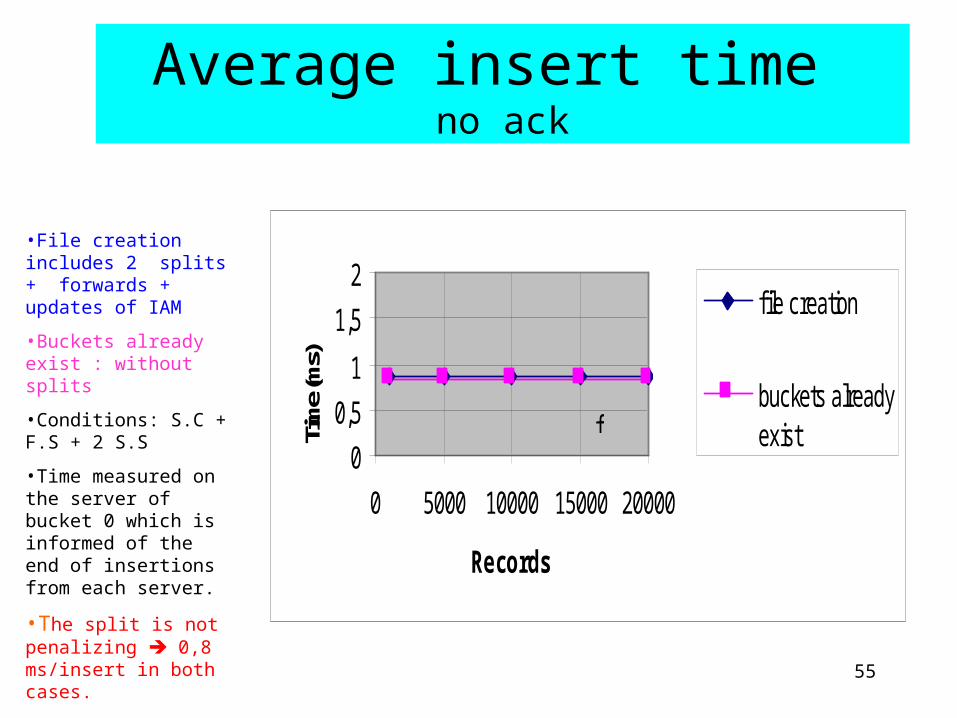
Average insert time no ack
•File creation includes 2 splits + forwards + updates of IAM
•Buckets already exist : without splits
•Conditions: S.C + F.S + 2 S.S
•Time measured on the server of bucket 0 which is informed of the end of insertions from each server.
•The split is not penalizing 0,8 ms/insert in both cases.
0
0,5
1
1,5
2
0 5000 10000 15000 20000
Records
Tim
e (m
s)f ile creation
buckets alreadyexistf

56
Average search time in 3 Slow Servers Configuration
S.S
J=2
S.S
J=1
F.C100 Mb/s
S.S
J=2
Bucket 0
Bucket 1
Bucket 2
UDP communication
Batch 1,2,3, …

57
The average key search time Fast Client & Slow Servers
3,3
1,57
1,08
3,3
1,571,43
0
0,5
1
1,5
2
2,5
3
3,5
0 1 2 3 4
Number of buckets
Tim
e (
ms
)
Balanced charge Non balanced charge
Records are sent in batch system : 1,2,3,…. 10000
•Balanced charge (load) : The 3 buckets receive the same number of records
•Non balanced charge : The bucket 1 receives more than the others
•conclusion : The curve is linear a good parallelism

58
ExtrapolationSingle 700 Mhz P3 server
Search time
Insertion time
Processor
Pentium II 350 Mhz Pentium 90 Mhz/ 4
F.S = 0,66 ms S.S = 3,3 ms* 5
F.S = 0,44 ms S.S = 2,37 ms* 5

59
Search time
Insertion time
Processor
Pentium II 350 Mhz Pentium 90 Mhz/ 4Pentium III 700 Mhz / 2
F.S = 0,66 ms S.S = 3,3 ms* 5
F.S = 0,44 ms S.S = 2,37 ms* 5
ExtrapolationExtrapolation
Single 700 Mhz P3 server

60
Search time
Insertion time
Processor
Pentium II 350 Mhz Pentium 90 Mhz/ 4Pentium III 700 Mhz / 2
F.S = 0,66 ms S.S = 3,3 ms* 5<= 0,33 ms * 2
F.S = 0,44 ms S.S = 2,37 ms* 5
ExtrapolationExtrapolation
Single 700 Mhz P3 server

61
Search time
Insertion time
Processor
Pentium II 350 Mhz Pentium 90 Mhz/ 4Pentium III 700 Mhz / 2
F.S = 0,66 ms S.S = 3,3 ms* 5<= 0,33 ms * 2
F.S = 0,44 ms S.S = 2,37 ms* 5<= 0,22 ms * 2
ExtrapolationExtrapolation
Single 700 Mhz P3 server

62
Extrapolation : Search time on fast P3 servers
The client is F.C
3 servers are 350 Mhz.P3: search time is 0,216 ms/ key
3 servers are 700 Mhz.: search time is 0,106 ms/ key
0
0,5
1
1,5
2
2,5
3
3,5
0 1 2 3 4
Number of buckets
Tim
e (m
s)
90 Mhz Extrapolation 350 Mhz
Extrapolation 700 Mhz

63
Extrapolation : Search time in file scaling to 100 servers
00,30,60,91,21,51,82,12,4
0 50 100
Number of servers
Tim
e (
ms) P. 90 Mhz
P. 350 Mhz
P. 700 Mhz

64
RP* schemesRP* schemes
• Produce 1-d ordered files– for range search
• Uses m-ary trees– like a B-tree
• Efficiently supports range queries– LH* also supports range queries
• but less efficiently
• Consists of the family of three schemes– RP*N RP*C and RP*S

65
Fig. 1 RP* design trade-offs
RP*N
RP*C
RP*S
No index all multicast
+ client index limited multicast
+ servers index optional multicast
RP* schemesRP* schemes

66
theofand
to
a
ofand
the
of
toa
of
of
and
the
of
to
a
of
in
that
is
and
theto
a
of
in
thatof
in
is
of
in
and
theto
a
of
in
that
of
in
it
of
in
i
is
and
theto
a
of
that
of
is
of
in
iin
infor
it
RP* file expansion
for
for
for
0 1 2 3
0 0
0 0
0
1
1
1
1 2
2

67
Comparison between LH*LH & RP*N
RP* LH*
Insertion in a 1 bucket without ack : 1 F.S & 1 S.C 0,81 1
Insertion in a 1 bucket without ack : 1 F.S & 2 S.C 0,75 0,44
Random search : F.S & 1 S.C 2,02 2,05
Random search : F.C & 1 S.S 4,62 3,3
Random search : F.C & 2 S.S 2,83 1,57
time/record (ms)

68
Scalable Distributed Log Structured Array (SDLSA)
• Intended for high-capacity SANs of IBM Ramac Virtual Arrays (RVAs) or Enterprise Storage Servers (ESSs)– One RVA contains up to 0.8 TB of data
– One EES contains up to 13 TB of data
• Reuse of current capabilities :– Transparent access to the entire SAN, as if it were one RVA or EES
– Preservation of current functions, • Log Structured Arrays
– for high-availability without small-write RAID penalty
• Snapshots
• New capabilities– Scalable TB databases
• PB databases for an EES SAN
– Parallel / distributed processing
– High-availability supporting an entire server node unavailability

69
Gross Architecture
SDLSA-bucket
SDLSA-bucket
SDLSA-bucket
SDLSA-bucket
Disk-bucket
RAM-bucket
Disk-bucket
RAM-bucket
Disk-bucket
RAM-bucket
Disk-bucket
RAM-bucket
SDLSA-client
SDLSA-client
SDRVA
RVA

70
Scalable Availability SDDS
• Support unavailability of k server sites• The factor k increases automatically with the file.
– Necessary to prevent the reliability decrease
• Moderate overhead for parity data– Storage overhead of O (1/k)
– Access overhead of k messages per data record insert or update
• Do not impare search and parallel scans– Unlike trivial adaptations of RAID like schemes.
• Several schemas were proposed around LH*– Different properties to best suit various applications – See http://ceria.dauphine.fr/witold.html

71
SDLSA : Main features
• LH* used as global addressing schema• RAM buckets split atomically• Disk buckets split in lazy way
– A record (logical track) moves only when • The client access it (update, or read)• It is garbage collected
– Atomic split of TB disk bucket would take hours
• The LH*RS schema is used for the high-availability
• Litwin W. Menon, J. Scalable Distributed Log Structured Arrays. CERIA Res. Rep. 12, 1999 http://ceria.dauphine.fr/witold.html

72
Conclusion
• SDDSs should be highly useful for HPC– Scalability– Fast access perfromance– Parallel scans & function shipping– High-availability
• SDDSs are available on network multicomputers– SDDS-2000
• Access performance prove at least an order of magnitude faster than to traditional files– Should reach two orders (100 times improvement) for 700 Mhz P3 – Combination of fast net & distributed RAM
73
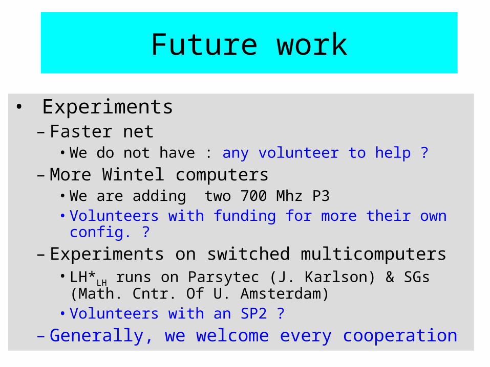
Future work
• Experiments– Faster net
• We do not have : any volunteer to help ?
– More Wintel computers• We are adding two 700 Mhz P3• Volunteers with funding for more their own config. ?
– Experiments on switched multicomputers• LH*LH runs on Parsytec (J. Karlson) & SGs (Math. Cntr. Of
U. Amsterdam)• Volunteers with an SP2 ?
– Generally, we welcome every cooperation

74
Thank You for Your Attention
Sponsored byHP Laboratories
IBM Almaden ResearchMicrosoft Research

75