plane table survey
TRANSCRIPT

GOVERNMENT ENGINEERING COLLEGE, BHAVNAGAR.
Civil Engineering Department

SURVEYING
• Topic:- Plane Table Surveying
CONTENTS
• Introduction.• Plane Table and Accessories.• Setting up the Plane Table in the Field.• Plane Tabling Methods.• Adjustments Of the Plane Table.• Errors in Plane Tabling.• Merits and Demerits.

INTRODUCTION
• Plane Tabling is a graphical method of surveying in which the field work and plotting are done simultaneously.
• Useful to fill in details between stations fixed by triangulation or theodolite traversing.
• Particularly adapted for small scale or medium scale mapping in which great accuracy in detail is not required.
• It is ideally suited to filling in details on a map already prepared and available on the drawing sheet.

PLANE TABLE ACCESSORIES
• Plane Table• Alidade• Spirit Level• Compass• Plumbing Fork• Drawing Paper

PLANE TABLE
• The plane table is a well-seasoned, good quality drawing board, varying size from 45 cm to 75 cm.
• A drawing sheet can be placed and fixed on this table.• There are three types of Plane Table:-
• Simple Plane Table• Johnson’s Plane Table• Coast Survey Table

PLANE TABLE

ALIDADE
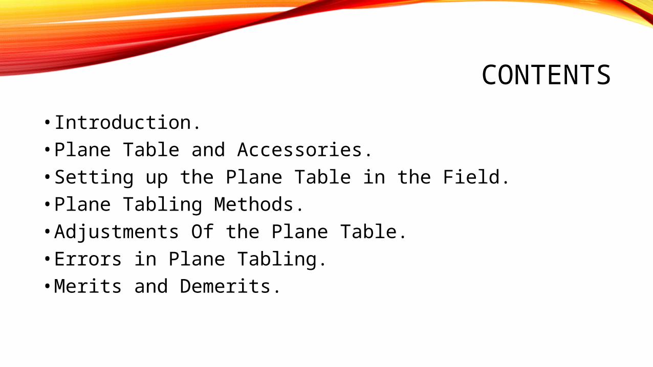
• An Alidade is a sighting instrument.
• There are Two types of Alidade:-• Plane Alidade• Telescopic Alidade

PLANE ALIDADE
• Consists of a metal (brass or gunmetal) or boxwood straight edge or ruler about 50 cm long.
• The beveled (ruling or working) edge of the alidade is called the fiducial edge.
• It consists of two vanes at the ends, the vanes are hinged and can be folded when the alidade is not in use.
• One of the sight vanes is provided with a narrow slit and the other with a central vertical wire or hair.
• One of the vanes known as sight vane is provided with a narrow slit with three holes, one at the top, one at the bottom and one in the middle.

PLANE ALIDADE
• The other vane which is known as object vane, is open and carried a hair or a fine thread or a thin wire stretched between the top and bottom of the slit.
• With the help of the slit, a definite line of sight may be established parallel to the ruling edge of the alidade.
• The length of the ruling edge should be equal to the smaller side of the plane table.
• A plane alidade can be used only when the elevations of the of the objects are low.

PLANE ALIDADESight Vane
Object Vane
Fiducial Edge
PLANE ALIDADE

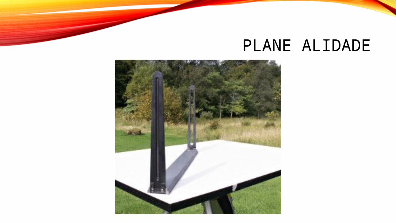
TELESCOPIC ALIDADE
• The alidade which is fitted with a telescope is known as a telescopic alidade.
• It is used to take inclined sights.• It increases the range and accuracy of the sights.• It consists of a small telescope with a level tube.• A graduated scale is mounted on the horizontal axis.• One side of the metal ruler is used as the working edge
along which lines are drawn.• The angles of elevation or depression can be read on the
vertical circle.
TELESCOPIC ALIDADE
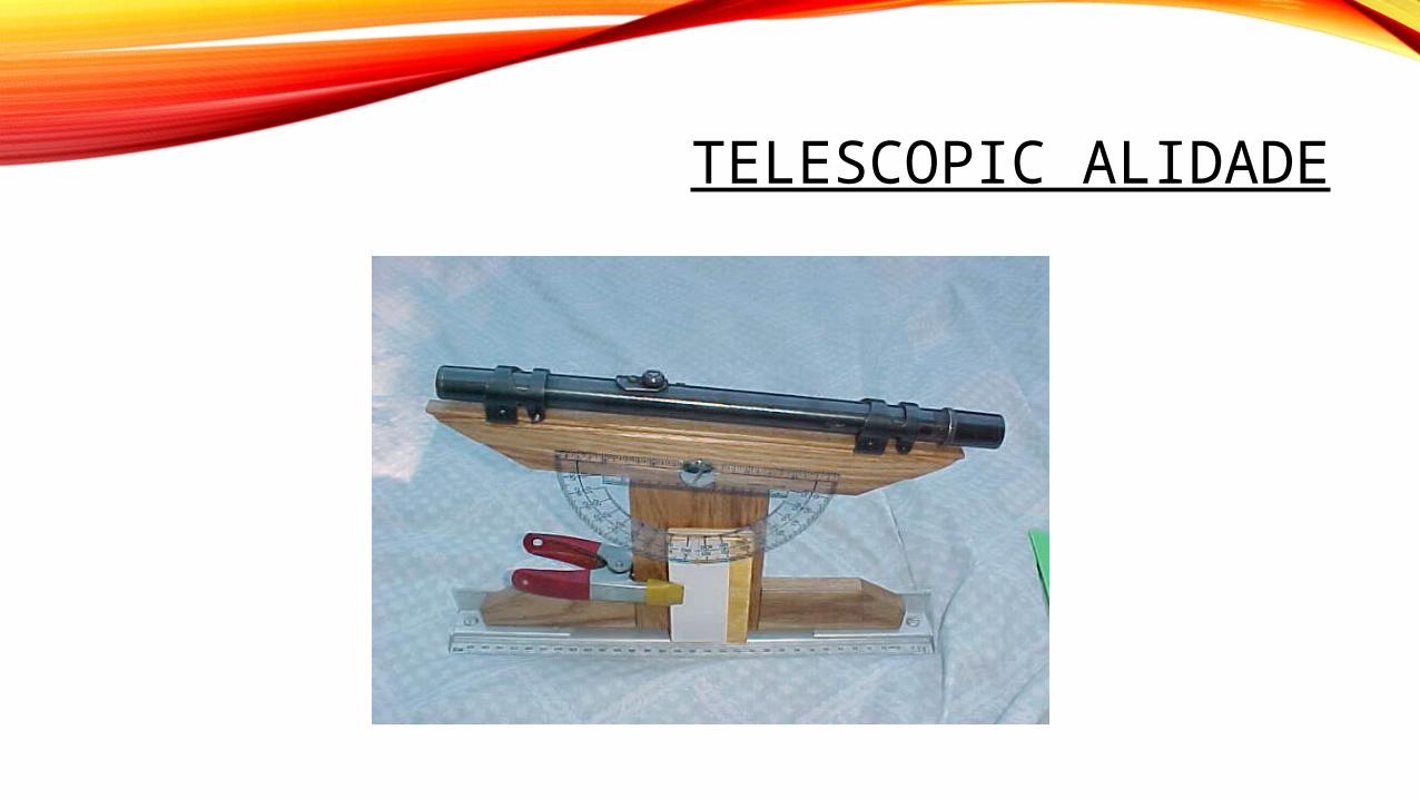
SPIRIT LEVEL
• It consists of a small metal tube which contains a small bubble.
• The spirit level may also be circular but its base must be flat so that it can be laid on the table.
• The table is truly level when the bubble remains central all over the table.

SPIRIT LEVEL
THE MAGNETIC COMPASS
• A box compass consists of a magnetic needle pivoted at its centre freely.
• It is used for orienting the plane table to magnetic north.
• The edges of the box compass are straight and the bottom is perfectly flat.

THE MAGNETIC COMPASS

PLUMBING FORK
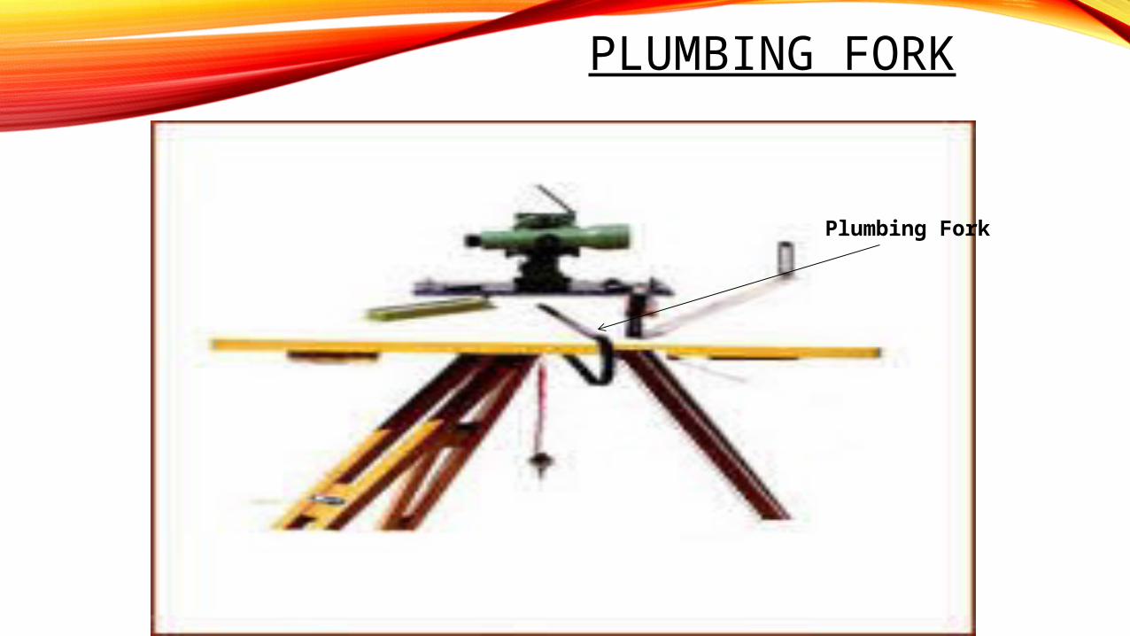
• The plumbing fork consists of a hair pin-shaped brass frame, having two equal arms.
• One end has a pointer while a plumb bob is attached the other end.
• It is used in large scale survey for accurate centering of the station location on the table over its ground position.

PLUMBING FORK
• It is also used for transferring the location of the instrument station on the sheet on to the ground.
• The fork is placed with its upper arm lying on the top of the table and the lower arm below it. The table is said to be centered when the plumb bob hangs freely over ground mark.
PLUMBING FORK
Plumbing Fork

SETTING UP THE PLANE TABLE
Setting up the Plane Table in the Field.• The table should be set up at a convenient height. (say about
1m). The legs of the tripod should be spread well apart, and firmly fixed into the ground in such a way that the table is approximately level.
Levelling the table• In this operation, the table top is made truly horizontal. For
rough and small scale work, leveling can be done by eye estimation whereas for accurate and large scale work, leveling achieved with an ordinary spirit level. The leveling is specially important in hilly terrain where some of the control points are situated at higher level and some other at lower level. The dislevelling of the plane table, throws the location of the point considerably out of its true location.

SETTING UP THE PLANE TABLE
Centring the table:• The table should be so placed over the station on the ground
that the point plotted on the sheet corresponding to the station occupied should be exactly over the station on the ground. This operation is known as the centering of the table. This may be done using a plumbing fork or U frame.
Orienting the plane table:• The operation of keeping the table at each of the successive
stations parallel to the position which it occupied at the first station is known as orientation. It is necessary when the instrument has to be set up at more than one station.

SETTING UP THE PLANE TABLE
ORIENTING THE PLANE TABLE:
• There are two methods of orienting the table:1. Orientation by the Magnetic Needle2. Orientation by Back sighting

ORIENTING BY MAGNETIC NEEDLE
• This method is used when it is not possible to bisect the previous station from the new station. This method is not much reliable and prone to errors due to variations of magnetic field.

ORIENTING BY BACKSIGHTING
• In this method the table is orientated by back sighting through the ray which is drawn from the previous station. This is the most accurate and reliable method of orientation of plane table.

METHODS OF PLANE TABLING
There are four methods of surveying with the plane table: a) Radiation Methodb) Intersection Methodc) Traversing Methodd) Resection Method

RADIATION METHOD
• In this method the objects are located by radiating lines from the point, and measuring the distance with chain or tape with suitable scale.
• It is chiefly used for locating the details from the station, which have been established previously by other methods triangulation, or traversing.

A
C
B
F
E
a
b c
d
e
f
P
RADIATION METHOD

INTERSECTION METHOD
• In this method the point is fixed on the plane by the intersection of the rays drawn from the two instrument stations.
• The line joining the stations is called Base line.
• The method requires only the linear measurements of this line.

A
B C
D
p
F
P Q
BASE LINE
d
cba
f e
q
E
INTERSECTION METHOD

TRAVERSING METHOD
• This is similar to that of Compass Survey or Transit Traversing.
• It is used for running survey lines between stations, which have been previously fixed by other methods of survey, to locate the topographic details.
• It is also suitable for the survey of roads, rivers, etc.

A
B
CD
a b
cd
eE
a
a
b
a
b
c
a b
cd
TRAVERSING METHOD
RESECTION METHOD
• This method is used for establishing the instrument stations only.
• A Characteristic feature of this resection is that the objective is to plot the station occupied by the table on the sheet rather than obtaining other station or plotting the details.
• After fixing the stations, details are located either by radiation or intersection.

A C
RESECTION METHOD
a c
B
a
b
c

ADJUSTMENT OF THE PLANE TABLE
• The surface of the board should be perfectly plane.• The vertical axis of the instrument is the line through the
centre of the ball and socket arrangement or the levelling head or any other arrangement provided. When this axis is vertical, the plane of the board should be horizontal.
• The ruling or fiducial edge of the alidade should be straight.
• The sight vanes of the alidade should be perpendicular to the base of the ruler.

ERRORS IN PLANE TABLING Following precautionary measures should be taken while
performing field work:o The table must be accurately oriented once the table is shifted.o The alidade should be correctly centred on the station point on
paper.o The expansion and contraction of paper should be taken care
off.oThe table should accurately centred.o The rays should be accurately drawn through the station
points.o Table should be sufficiently clamped.o The board should be horizontal.o The objects should be accurately sighted
MERITS OF PLANE TABLINGi) It is most suitable for preparing small-scale maps.
ii) It is most rapid.
iii) The field book is not necessary as plotting is done in the field concurrently with the field work, and hence the mistakes in booking the field notes are avoided.
iv) The surveyor can compare the plotted work with the actual features of the area surveyed and thus can ascertain if it represents them properly.
v) It is particularly advantageous in magnetic areas where compass survey is not reliable.
vi) It is less costly than a theodolite survey.
vii)No great skill is required to prepare a satisfactory map.

DEMERITS OF PLANE TABLING
i) It is not suitable for work in a wet climate.ii) It is heavy, cumbersome and awkward to carry.iii) There are several accessories to be carried, and,
therefore, they are likely to be lost.iv) It is not intended for accurate work.v) If the survey is to be re-plotted to a different scale or
quantities are to be computed, it is a great inconvenience in absence of the field notes.

THANK YOU FOR BEARING
By, Nitin Charel – 130210106011 Kartik Hingol – 130210106030 Bhavik Shah – 130210106049 Digvijay Solanki – 130210106055