planning a network upgrade - pearson europe, middle east & africa
TRANSCRIPT
CHAPTER 3
Planning a Network Upgrade
ObjectivesAfter completing this chapter, you should be able to answer the following questions:
■ Why is proper planning necessary when youperform a network upgrade?
■ What is a site survey, and why is it necessary?
■ What steps are involved in performing a site survey?
■ What is structured cabling?
■ What factors must you consider when upgradingLAN and internetworking devices?
Key TermsThis chapter uses the following key terms. You can find the definitions in the glossary.
site survey 50
SWOT 55
failure domain 64
Cisco IOS 65
Integrated Services Router (ISR) 65
Fault tolerance 68
04_2109_ch03.qxd 4/8/08 3:31 PM Page 49
As businesses grow and evolve, they may outgrow their existing network and require a networkupgrade. To help ensure a smooth transition, a careful look at both the current network and the newnetwork requirements is necessary. This will help determine what new equipment and configurationsare necessary to ensure that the new network fully supports both the current and future needs of thecompany or organization.
Part II of this book includes the corresponding labs for this chapter.
Common IssuesWhen a small company grows rapidly, the original network that supported the company often cannotkeep pace with the expansion. Employees at the company may not realize how important it is to properlyplan for network upgrades. In many cases, the business may just add various network hardware devices,of varying quality, from different manufacturers, and different network connection technologies, toconnect new users. Often this causes a degradation in the quality of the network as each new user ordevice is added. If this continues, at some point the network is unable to properly support the typesand level of network traffic that the users generate. Only when the network starts to fail do most smallbusinesses look for help to redesign the network. An ISP or managed service provider may be calledin to provide advice and to install and maintain the network upgrade.
Before a network upgrade can be properly designed, an onsite technician is dispatched to perform asite survey to document the existing network structure. It is also necessary to investigate and documentthe physical layout of the premises to determine where new equipment can be installed.
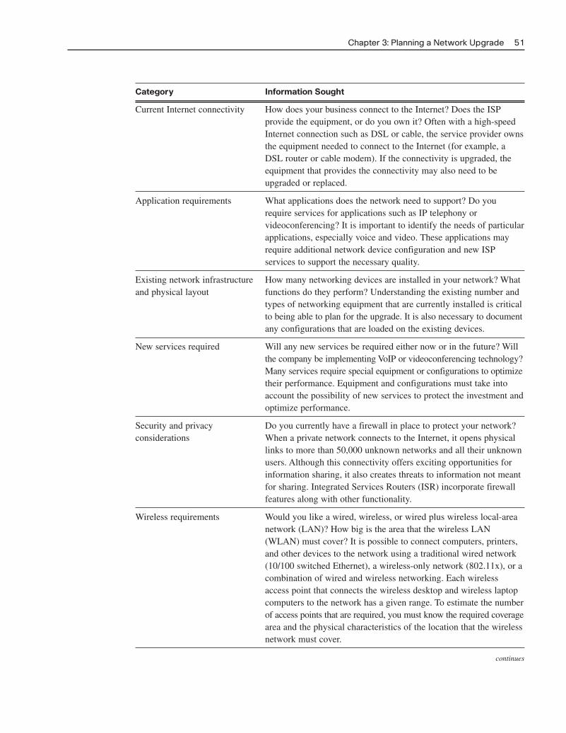
Site SurveyA site survey can give the network designer a substantial amount of information and create a properstarting point for the project. It shows what is already on site and indicates what is needed. A salesrepresentative may accompany the technician to the site to interview the customer as well. A propersite survey gathers as much information as possible about the current business and its projectedgrowth. This information is gathered from different people in an attempt to accurately forecast the cur-rent and future network requirements. Table 3-1 lists the information sought in a site survey.
Table 3-1 Site Survey Information
Category Information Sought
Number of users and How many network users, printers, and servers will the network types of equipment support? To determine the number of network users the network
must support, be sure to consider how many users will be added over the next 12 months, and how many network printers and network servers the network has to accommodate.
Projected growth What is the expected growth in the company or organization? Will the company be hiring new employees who must be provided with access to network resources? Will a new branch office be opened that will require connectivity? A network is a long-term investment. Planning for future growth now can save a great deal of time,money, and frustration in the future.
50 Working at a Small-to-Medium Business or ISP, CCNA Discovery Learning Guide
04_2109_ch03.qxd 4/8/08 3:31 PM Page 50
Category Information Sought
Current Internet connectivity How does your business connect to the Internet? Does the ISP provide the equipment, or do you own it? Often with a high-speed Internet connection such as DSL or cable, the service provider owns the equipment needed to connect to the Internet (for example, a DSL router or cable modem). If the connectivity is upgraded, the equipment that provides the connectivity may also need to be upgraded or replaced.
Application requirements What applications does the network need to support? Do you require services for applications such as IP telephony or videoconferencing? It is important to identify the needs of particular applications, especially voice and video. These applications may require additional network device configuration and new ISP services to support the necessary quality.
Existing network infrastructure How many networking devices are installed in your network? What and physical layout functions do they perform? Understanding the existing number and
types of networking equipment that are currently installed is critical to being able to plan for the upgrade. It is also necessary to document any configurations that are loaded on the existing devices.
New services required Will any new services be required either now or in the future? Will the company be implementing VoIP or videoconferencing technology? Many services require special equipment or configurations to optimize their performance. Equipment and configurations must take into account the possibility of new services to protect the investment and optimize performance.
Security and privacy Do you currently have a firewall in place to protect your network? considerations When a private network connects to the Internet, it opens physical
links to more than 50,000 unknown networks and all their unknown users. Although this connectivity offers exciting opportunities for information sharing, it also creates threats to information not meant for sharing. Integrated Services Routers (ISR) incorporate firewall features along with other functionality.
Wireless requirements Would you like a wired, wireless, or wired plus wireless local-area network (LAN)? How big is the area that the wireless LAN (WLAN) must cover? It is possible to connect computers, printers,and other devices to the network using a traditional wired network (10/100 switched Ethernet), a wireless-only network (802.11x), or a combination of wired and wireless networking. Each wireless access point that connects the wireless desktop and wireless laptop computers to the network has a given range. To estimate the number of access points that are required, you must know the required coverage area and the physical characteristics of the location that the wireless network must cover.
continues
Chapter 3: Planning a Network Upgrade 51
04_2109_ch03.qxd 4/8/08 3:31 PM Page 51
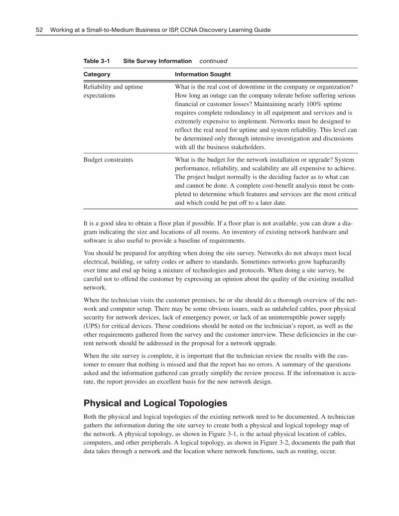
Table 3-1 Site Survey Information continued
Category Information Sought
Reliability and uptime What is the real cost of downtime in the company or organization? expectations How long an outage can the company tolerate before suffering serious
financial or customer losses? Maintaining nearly 100% uptime requires complete redundancy in all equipment and services and is extremely expensive to implement. Networks must be designed to reflect the real need for uptime and system reliability. This level can be determined only through intensive investigation and discussions with all the business stakeholders.
Budget constraints What is the budget for the network installation or upgrade? System performance, reliability, and scalability are all expensive to achieve. The project budget normally is the deciding factor as to what can and cannot be done. A complete cost-benefit analysis must be com-pleted to determine which features and services are the most critical and which could be put off to a later date.
It is a good idea to obtain a floor plan if possible. If a floor plan is not available, you can draw a dia-gram indicating the size and locations of all rooms. An inventory of existing network hardware andsoftware is also useful to provide a baseline of requirements.
You should be prepared for anything when doing the site survey. Networks do not always meet localelectrical, building, or safety codes or adhere to standards. Sometimes networks grow haphazardlyover time and end up being a mixture of technologies and protocols. When doing a site survey, becareful not to offend the customer by expressing an opinion about the quality of the existing installednetwork.
When the technician visits the customer premises, he or she should do a thorough overview of the net-work and computer setup. There may be some obvious issues, such as unlabeled cables, poor physicalsecurity for network devices, lack of emergency power, or lack of an uninterruptible power supply(UPS) for critical devices. These conditions should be noted on the technician’s report, as well as theother requirements gathered from the survey and the customer interview. These deficiencies in the cur-rent network should be addressed in the proposal for a network upgrade.
When the site survey is complete, it is important that the technician review the results with the cus-tomer to ensure that nothing is missed and that the report has no errors. A summary of the questionsasked and the information gathered can greatly simplify the review process. If the information is accu-rate, the report provides an excellent basis for the new network design.
Physical and Logical TopologiesBoth the physical and logical topologies of the existing network need to be documented. A techniciangathers the information during the site survey to create both a physical and logical topology map ofthe network. A physical topology, as shown in Figure 3-1, is the actual physical location of cables,computers, and other peripherals. A logical topology, as shown in Figure 3-2, documents the path thatdata takes through a network and the location where network functions, such as routing, occur.
52 Working at a Small-to-Medium Business or ISP, CCNA Discovery Learning Guide
04_2109_ch03.qxd 4/8/08 3:31 PM Page 52
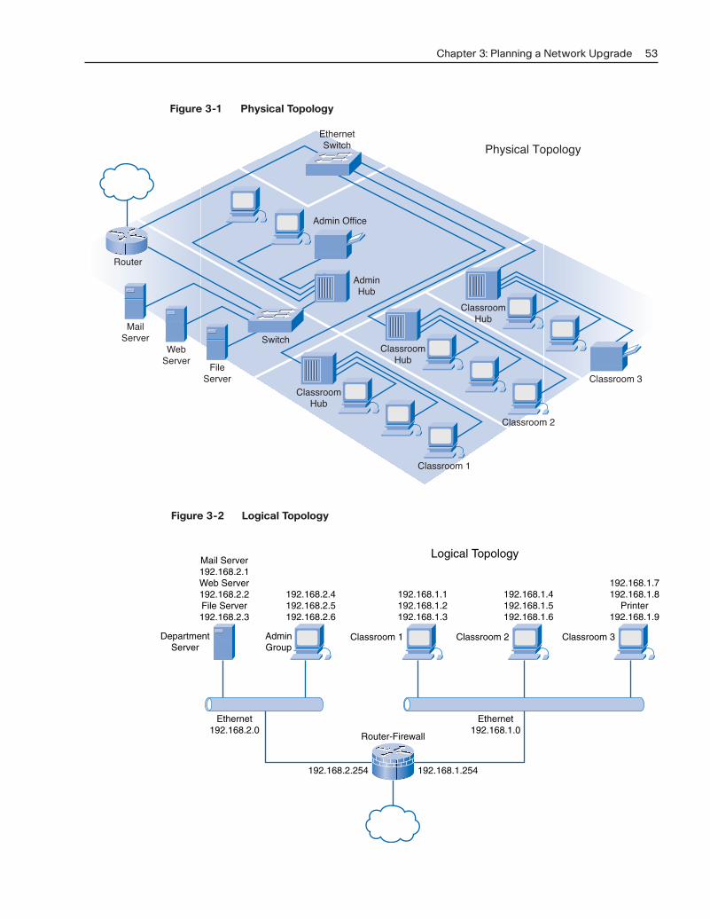
Figure 3-1 Physical Topology
Chapter 3: Planning a Network Upgrade 53
EthernetSwitch Physical Topology
Switch
AdminHub
Admin Office
MailServer
WebServer
FileServer Classroom 3
ClassroomHub
ClassroomHub
Classroom 1
Classroom 2
ClassroomHub
Router
Figure 3-2 Logical Topology
192.168.1.254192.168.2.254
Logical TopologyMail Server192.168.2.1Web Server192.168.2.2File Server192.168.2.3
192.168.2.4192.168.2.5192.168.2.6
DepartmentServer
AdminGroup
Ethernet192.168.2.0
Ethernet192.168.1.0
Router-Firewall
192.168.1.1192.168.1.2192.168.1.3
Classroom 1
192.168.1.4192.168.1.5192.168.1.6
Classroom 2
192.168.1.7192.168.1.8
Printer192.168.1.9
Classroom 3
04_2109_ch03.qxd 4/8/08 3:31 PM Page 53
In a wired network, the physical topology map consists of the wiring closet, as well as the wiring tothe individual end-user stations. In a wireless network, the physical topology consists of the wiringcloset and any access points that may be installed. Because there are no wires, the physical topologycontains the wireless signal coverage area.
The logical topology generally is the same for both a wired and wireless network. It includes the namingand Layer 3 addressing of end stations, router gateways, and other network devices, regardless of thephysical location. It indicates the location of routing, network address translation, and firewall filtering.
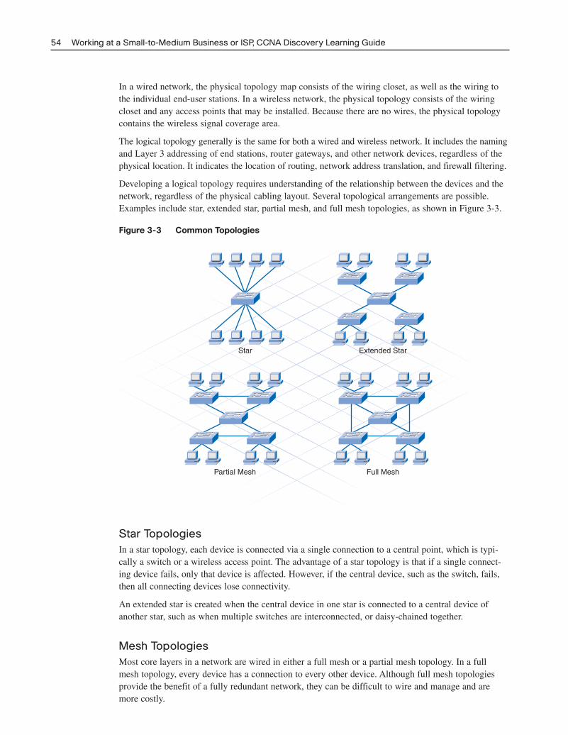
Developing a logical topology requires understanding of the relationship between the devices and thenetwork, regardless of the physical cabling layout. Several topological arrangements are possible.Examples include star, extended star, partial mesh, and full mesh topologies, as shown in Figure 3-3.
Figure 3-3 Common Topologies
54 Working at a Small-to-Medium Business or ISP, CCNA Discovery Learning Guide
Star TopologiesIn a star topology, each device is connected via a single connection to a central point, which is typi-cally a switch or a wireless access point. The advantage of a star topology is that if a single connect-ing device fails, only that device is affected. However, if the central device, such as the switch, fails,then all connecting devices lose connectivity.
An extended star is created when the central device in one star is connected to a central device ofanother star, such as when multiple switches are interconnected, or daisy-chained together.
Mesh TopologiesMost core layers in a network are wired in either a full mesh or a partial mesh topology. In a fullmesh topology, every device has a connection to every other device. Although full mesh topologiesprovide the benefit of a fully redundant network, they can be difficult to wire and manage and aremore costly.
Star Extended Star
Partial Mesh Full Mesh
04_2109_ch03.qxd 4/8/08 3:31 PM Page 54
A partial mesh topology is used for larger installations. In a partial mesh topology, each device is connected to at least two other devices. This arrangement creates sufficient redundancy, without thecomplexity of a full mesh.
Implementing redundant links through partial or full mesh topologies ensures that network devicescan find alternative paths to send data in the event of a failure.
Network Requirements DocumentationAlong with creating the topology maps for the existing network, it is necessary to obtain additionalinformation about the hosts and networking devices that are currently installed in the network. Recordthis information on a brief inventory sheet. In addition to currently installed equipment, document anyplanned growth that the company anticipates in the near future. This information helps the networkdesigner determine what new equipment is required and the best way to structure the network to support the anticipated growth.
The inventory sheet of all the devices installed on the network includes the following:
■ Device name
■ Date of purchase
■ Warranty information
■ Location
■ Brand and model
■ Operating system
■ Logical addressing information
■ Connection information
■ Security information
Creating Network Diagrams (3.1.3)
In this activity, you create a logical diagram and inventory list for a network. Use file d2-313 on theCD-ROM that accompanies this book to perform this activity using Packet Tracer.
Planning the Network UpgradeExtensive planning should go into a network upgrade. As with any project, a need is first identified, andthen a plan outlines the upgrade process from beginning to end. A good project plan helps identify anystrengths, weaknesses, opportunities, and threats. This is called a SWOT analysis. The plan shouldclearly define the tasks and the order in which tasks are completed.
Some common examples of good planning include
■ Sports teams following game plans
■ Builders following blueprints
■ Ceremonies or meetings following agendas
Chapter 3: Planning a Network Upgrade 55
Packet Tracer Activity
04_2109_ch03.qxd 4/8/08 3:31 PM Page 55

Network UpgradesA network that is a patchwork of devices strung together using a mixture of technologies and protocolsusually indicates poor or no initial planning. These types of networks are susceptible to downtime andare extremely difficult to maintain and troubleshoot. Unfortunately, this type of network is often encounteredas small businesses experience rapid, unexpected growth. Even larger organizations often experienceunplanned growth in their networks when they acquire or merge with other organizations. Organizationsthat experience a controlled rate of growth can properly plan their network to avoid problems and givetheir users an acceptable level of service.
The planning of a network upgrade begins after the initial site survey and report are complete. It consistsof five distinct phases:
■ Phase 1: Requirements gathering
■ Phase 2: Selection and design
■ Phase 3: Implementation
■ Phase 4: Operation
■ Phase 5: Review and evaluation
The next sections describe each phase in greater detail.
Phase 1: Requirements GatheringAfter all the information has been gathered from the customer and the site visit, the design team at theISP analyzes the information to determine network requirements and then generates an analysis report.If insufficient information is available to properly determine the best network upgrade path to follow,this team may request additional information.
Phase 2: Selection and DesignWhen the analysis report is complete, devices and cabling are selected. The design team creates multipledesigns and shares them with other members on the project. This allows team members to view theLAN from a documentation perspective and evaluate trade-offs in performance and cost. It is duringthis step that any weaknesses of the design can be identified and addressed. Also during this phase,prototypes are created and tested. A successful prototype is a good indicator of how the new networkwill operate.
Phase 3: ImplementationIf the first two steps are done correctly, the implementation phase may be performed without incident.If tasks were overlooked in the earlier phases, they must be corrected during implementation. A goodimplementation schedule must allow time for unexpected events and also schedules events to keep disruption of the customer’s business to a minimum. Staying in constant communication with the customer during the installation is critical to the project’s success.
Phase 4: OperationWhen the network implementation phase is complete, the network moves into a production environment.In this environment, the network is considered live and performs all the tasks it has been designed toaccomplish. If all steps up to this point have been properly completed, very few unexpected incidentsshould occur when the network moves into the operation phase.
56 Working at a Small-to-Medium Business or ISP, CCNA Discovery Learning Guide
04_2109_ch03.qxd 4/8/08 3:31 PM Page 56

Phase 5: Review and EvaluationAfter the network is operational, the design and implementation must be reviewed and evaluated againstthe original design objectives. This is usually done by members of the design team with assistance fromthe network staff. This evaluation includes costs, performance, and appropriateness for the environment.For this process, the following items are recommended:
■ Compare the user experience with the goals in the documentation, and evaluate whether thedesign is right for the job.
■ Compare the projected designs and costs with the actual deployment. This ensures that futureprojects will benefit from the lessons learned on this project.
■ Monitor the operation, and record changes. This ensures that the system is always fully documentedand accountable.
It is important that, at each phase, careful planning and review occur to ensure that the project goessmoothly and the installation is successful. Onsite technicians are often included in all phases of theupgrade, including planning. This allows them to gain a better understanding of the expectations andlimitations of the network upgrade and to give the end users a much-improved level of service.
Activity 3-1: Network Planning Phases (3.2.1)
In this activity, you determine at which phase of the network planning process certain events occur.Use file d2ia-321 on the CD-ROM that accompanies this book to perform this interactive activity.
Physical EnvironmentBefore selecting equipment and determining the design of the new network, the network designermust examine the existing network facilities and cabling. This is part of the initial site survey. Thefacilities include the physical environment, the telecommunication room, and the existing networkwiring. A telecommunications room or wiring closet in a small, single-floor network is usually calledthe main distribution facility (MDF). Figure 3-4 shows a small office environment with a single MDF.
Figure 3-4 Main Distribution Facility
Chapter 3: Planning a Network Upgrade 57
AdministrativeManager
TemporaryWorker Film EditorOffice Area for Mobile
Workers
Conference/Lounge Area
TelecommunicationsRoom
04_2109_ch03.qxd 4/8/08 3:31 PM Page 57
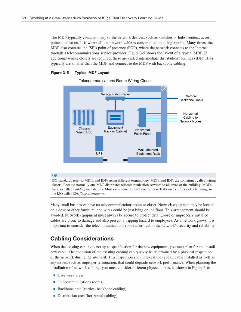
The MDF typically contains many of the network devices, such as switches or hubs, routers, accesspoints, and so on. It is where all the network cable is concentrated in a single point. Many times, theMDF also contains the ISP’s point of presence (POP), where the network connects to the Internetthrough a telecommunications service provider. Figure 3-5 shows the layout of a typical MDF. If additional wiring closets are required, these are called intermediate distribution facilities (IDF). IDFstypically are smaller than the MDF and connect to the MDF with backbone cabling.
Figure 3-5 Typical MDF Layout
58 Working at a Small-to-Medium Business or ISP, CCNA Discovery Learning Guide
Telecommunications Room Wiring Closet
Vertical Patch Panel
EquipmentRack or Cabinet
ChassisWiring Hub
HorizontalPatch Panel
VerticalBackbone Cable
HorizontalCabling to
Network Nodes
Wall-MountedEquipment RackUPS
TipISO standards refer to MDFs and IDFs using different terminology. MDFs and IDFs are sometimes called wiringclosets. Because normally one MDF distributes telecommunication services to all areas of the building, MDFsare also called building distributors. Most environments have one or more IDFs on each floor of a building, sothe ISO calls IDFs floor distributors.
Many small businesses have no telecommunications room or closet. Network equipment may be locatedon a desk or other furniture, and wires could be just lying on the floor. This arrangement should beavoided. Network equipment must always be secure to protect data. Loose or improperly installedcables are prone to damage and also present a tripping hazard to employees. As a network grows, it isimportant to consider the telecommunications room as critical to the network’s security and reliability.
Cabling ConsiderationsWhen the existing cabling is not up to specification for the new equipment, you must plan for and installnew cable. The condition of the existing cabling can quickly be determined by a physical inspectionof the network during the site visit. This inspection should reveal the type of cable installed as well asany issues, such as improper termination, that could degrade network performance. When planning theinstallation of network cabling, you must consider different physical areas, as shown in Figure 3-6:
■ User work areas
■ Telecommunications rooms
■ Backbone area (vertical backbone cabling)
■ Distribution area (horizontal cabling)
04_2109_ch03.qxd 4/8/08 3:31 PM Page 58
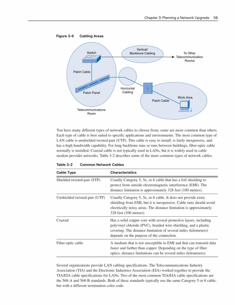
Figure 3-6 Cabling Areas
Chapter 3: Planning a Network Upgrade 59
HorizontalCabling
Vertical/Backbone Cabling To Other
TelecommunicationRooms
Patch CableWork Area
Switch
Patch Cable
Patch Panel
TelecommunicationsRoom
You have many different types of network cables to choose from; some are more common than others.Each type of cable is best suited to specific applications and environments. The most common type ofLAN cable is unshielded twisted-pair (UTP). This cable is easy to install, is fairly inexpensive, andhas a high bandwidth capability. For long backbone runs or runs between buildings, fiber-optic cablenormally is installed. Coaxial cable is not typically used in LANs, but it is widely used in cablemodem provider networks. Table 3-2 describes some of the more common types of network cables.
Table 3-2 Common Network Cables
Cable Type Characteristics
Shielded twisted-pair (STP) Usually Category 5, 5e, or 6 cable that has a foil shielding to protect from outside electromagnetic interference (EMI). The distance limitation is approximately 328 feet (100 meters).
Unshielded twisted-pair (UTP) Usually Category 5, 5e, or 6 cable. It does not provide extra shielding from EMI, but it is inexpensive. Cable runs should avoid electrically noisy areas. The distance limitation is approximately 328 feet (100 meters).
Coaxial Has a solid copper core with several protective layers, including polyvinyl chloride (PVC), braided wire shielding, and a plastic covering. The distance limitation of several miles (kilometers) depends on the purpose of the connection.
Fiber-optic cable A medium that is not susceptible to EMI and that can transmit data faster and farther than copper. Depending on the type of fiber optics, distance limitations can be several miles (kilometers).
Several organizations provide LAN cabling specifications. The Telecommunications IndustryAssociation (TIA) and the Electronic Industries Association (EIA) worked together to provide theTIA/EIA cable specifications for LANs. Two of the most common TIA/EIA cable specifications arethe 568-A and 568-B standards. Both of these standards typically use the same Category 5 or 6 cable,but with a different termination color code.
04_2109_ch03.qxd 4/8/08 3:31 PM Page 59

Three different types of UTP cables are commonly encountered in the network environment:
■ Straight-through cables have the same pinout on both ends. They normally are used to connectdissimilar devices, such as a switch and a computer or a switch and a router.
■ Crossover cables have the transmit pins on one end connected to the receive pins on the other end.This type of cable is used to connect like devices, such as two computers, two switches, or tworouters. Crossover cables can also be used to connect a computer directly to a router interface.
■ A console cable or a rollover cable has the pinouts on each end reversed. Normally it is used toconnect the serial port of a computer to the console port of a router or switch to perform the initialconfiguration. Figure 3-7 shows typical uses of these cables.
Figure 3-7 Typical Uses of Cables
60 Working at a Small-to-Medium Business or ISP, CCNA Discovery Learning Guide
Category 5 or 6 Crossover Cables
Category 5 or 6 Straight-Through Cables
Console Cable
Another type of cable that is common in networks is a serial cable. A serial cable typically is used toconnect the router to an Internet connection. This Internet connection may be to the phone company,the cable company, or a private ISP.
Structured CableWhen designing a structured cabling project, the first step is to obtain an accurate floor plan. Thefloor plan allows the technician to identify possible wiring closet locations, cable runs, and whichelectrical areas to avoid.
After the technician has identified and confirmed the locations of network devices, it is time to drawthe network on the floor plan. Some of the more important items to document include the following:
■ Patch cable: A short cable from the computer to the wall plate in the user work area.
■ Horizontal cable: A cable from the wall plate to the IDF in the distribution area.
■ Vertical cable: A cable from the IDF to the MDF in the organization’s backbone area.
■ Backbone cable: The part of a network that handles the major traffic.
■ Location of wiring closet: An area to concentrate the end-user cable to the hub or switch.
■ Cable management system: A series of trays and straps used to guide and protect cable runs.
■ Cable labeling system: A proper labeling system or scheme that identifies cables.
■ Electrical considerations: The premises should have adequate outlets to support the electricalrequirements of the network equipment.
04_2109_ch03.qxd 4/8/08 3:31 PM Page 60
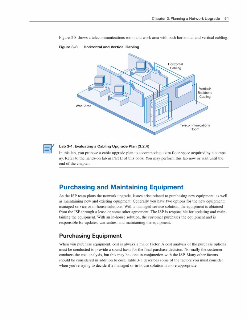
Figure 3-8 shows a telecommunications room and work area with both horizontal and vertical cabling.
Figure 3-8 Horizontal and Vertical Cabling
Chapter 3: Planning a Network Upgrade 61
HorizontalCabling
Vertical/BackboneCabling
TelecommunicationsRoom
Work Area
Lab 3-1: Evaluating a Cabling Upgrade Plan (3.2.4)
In this lab, you propose a cable upgrade plan to accommodate extra floor space acquired by a compa-ny. Refer to the hands-on lab in Part II of this book. You may perform this lab now or wait until theend of the chapter.
Purchasing and Maintaining EquipmentAs the ISP team plans the network upgrade, issues arise related to purchasing new equipment, as wellas maintaining new and existing equipment. Generally you have two options for the new equipment:managed service or in-house solutions. With a managed service solution, the equipment is obtainedfrom the ISP through a lease or some other agreement. The ISP is responsible for updating and main-taining the equipment. With an in-house solution, the customer purchases the equipment and isresponsible for updates, warranties, and maintaining the equipment.
Purchasing EquipmentWhen you purchase equipment, cost is always a major factor. A cost analysis of the purchase optionsmust be conducted to provide a sound basis for the final purchase decision. Normally the customerconducts the cost analysis, but this may be done in conjunction with the ISP. Many other factorsshould be considered in addition to cost. Table 3-3 describes some of the factors you must considerwhen you’re trying to decide if a managed or in-house solution is more appropriate.
04_2109_ch03.qxd 4/8/08 3:31 PM Page 61
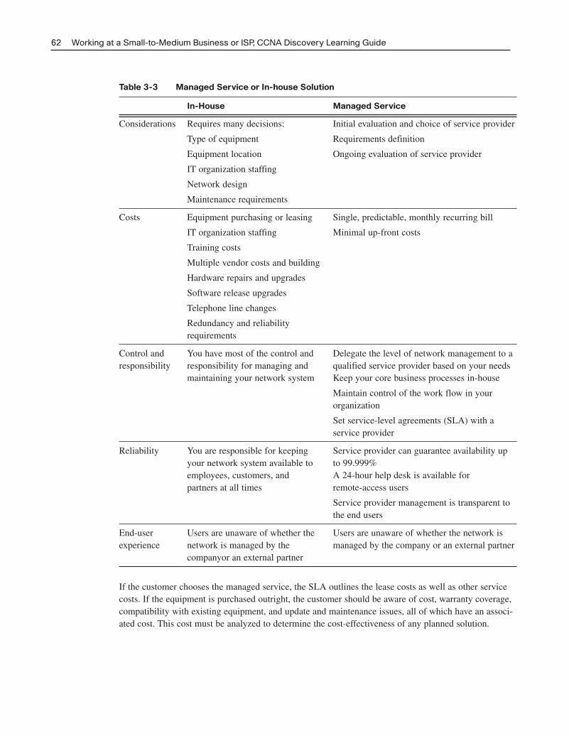
Table 3-3 Managed Service or In-house Solution
In-House Managed Service
Considerations Requires many decisions: Initial evaluation and choice of service provider
Type of equipment Requirements definition
Equipment location Ongoing evaluation of service provider
IT organization staffing
Network design
Maintenance requirements
Costs Equipment purchasing or leasing Single, predictable, monthly recurring bill
IT organization staffing Minimal up-front costs
Training costs
Multiple vendor costs and building
Hardware repairs and upgrades
Software release upgrades
Telephone line changes
Redundancy and reliability requirements
Control and You have most of the control and Delegate the level of network management to a responsibility responsibility for managing and qualified service provider based on your needs
maintaining your network system Keep your core business processes in-house
Maintain control of the work flow in your organization
Set service-level agreements (SLA) with a service provider
Reliability You are responsible for keeping Service provider can guarantee availability upyour network system available to to 99.999%employees, customers, and A 24-hour help desk is available for partners at all times remote-access users
Service provider management is transparent to the end users
End-user Users are unaware of whether the Users are unaware of whether the network is experience network is managed by the managed by the company or an external partner
companyor an external partner
If the customer chooses the managed service, the SLA outlines the lease costs as well as other servicecosts. If the equipment is purchased outright, the customer should be aware of cost, warranty coverage,compatibility with existing equipment, and update and maintenance issues, all of which have an associ-ated cost. This cost must be analyzed to determine the cost-effectiveness of any planned solution.
62 Working at a Small-to-Medium Business or ISP, CCNA Discovery Learning Guide
04_2109_ch03.qxd 4/8/08 3:31 PM Page 62
Selecting Network DevicesAfter the customer requirements have been analyzed, the design staff recommends the appropriate network devices to connect and support the new network functionality. Modern networks use a varietyof devices for connectivity. Each device has certain capabilities to control the flow of data across anetwork. A general rule is that the higher the device is in the OSI model, the more intelligent it is. Thismeans that a higher-level device can better analyze the data traffic and forward it based on informationnot available at lower layers. For example, a Layer 1 hub can only forward data out all ports, a Layer 2switch can filter the data and only send it out the port connected to the destination based on MACaddress, and a Layer 3 router can decide which traffic to forward or block based on the logical address.
As switches and routers evolve, the distinction between them becomes blurred. One simple distinctionremains: LAN switches provide connectivity within an organization’s LAN, whereas routers are neededto interconnect local networks or to form a wide-area network (WAN) environment.
In addition to switches and routers, other connectivity options are available for LANs. Wireless accesspoints allow computers and other devices, such as handheld Internet Protocol (IP) phones, to wirelesslyconnect to the network or share broadband connectivity. Firewalls guard against network threats andprovide application security, network control and containment, and secure connectivity technologies.ISRs combine the functionality of switches, routers, access points, and firewalls in the same networkingdevice.
Selecting LAN DevicesAlthough both a hub and a switch can provide connectivity at the access layer of a network, switchesshould be chosen for connecting devices to a LAN. Switches generally are more expensive than hubs,but the enhanced performance makes them cost-effective. A hub generally is chosen as a networkingdevice within a very small LAN, within a LAN that requires low throughput requirements, or whenfinances are limited. A hub may also be installed in a network when all network traffic is to be monitored.Hubs forward all traffic out all ports, whereas switches microsegment the network. Connecting a network-monitoring device to a hub allows the monitoring device to see all network traffic on that segment.Some switches do provide the ability to monitor all network traffic through a special port, but this isnot a universal feature.
When selecting a switch for a particular LAN, network designers need to consider a number of factors,including the following:
■ Speed and types of ports/interfaces
■ Expandability
■ Manageability
■ Cost
Speed and Types of Ports/InterfacesChoosing Layer 2 devices that can accommodate increased speeds allows the network to evolve withoutyour having to replace the central devices. It is a good idea to purchase the fastest ports available withinthe budgeted funds. A bit of extra money spent now can save a great deal of time and expense later,when it is time to upgrade the network again.
The same can be stated about the number and types of network ports. Network designers must carefullyconsider how many UTP and fiber ports are needed. It is important to estimate how many additionalports will be required to support network expansion in the future.
Chapter 3: Planning a Network Upgrade 63
04_2109_ch03.qxd 4/8/08 3:31 PM Page 63
ExpandabilityNetworking devices come in both fixed and modular physical configurations. Fixed configurations havea specific number and type of ports or interfaces and cannot be expanded. Modular devices have expansionslots that provide the flexibility to add new modules as requirements evolve. Most modular devicescome with a basic number of fixed ports as well as expansion slots.
A typical use of an expansion slot is to add fiber-optic modules to a device that was originally configuredwith a number of fixed UTP ports. Modular switches can be a cost-effective approach to scaling LANs.
ManageabilityA managed switch provides control over individual ports or over the switch as a whole. Typical controlsinclude the ability to monitor operation and change the settings for a device. A managed device can bemonitored for performance and security and typically provides enhancements to the monitoring andsecurity features. For example, with a managed switch, ports can be turned on or off as required tocontrol access. In addition, administrators can control which computers or devices are allowed to connectto a port.
CostThe cost of a switch is determined by its capacity and features. The switch capacity includes the numberand types of ports available and the overall throughput. Other factors that impact the cost are the switch’snetwork management capabilities, embedded security technologies, and optional advanced switchingtechnologies.
Using a simple cost-per-port calculation, it may appear initially that the best option is to deploy onelarge switch at a central location. However, this apparent cost savings may be offset by the expensefrom the longer cable lengths required to connect every device on the LAN to one central switch.Compare this option with the cost of deploying a number of smaller switches connected by a few longcables to a central switch.
Deploying a number of smaller devices instead of a single large device also has the benefit of reducingthe size of the failure domain. A failure domain is the area of the network affected when a piece ofnetworking equipment malfunctions or fails.
Exploring Different LAN Switch Options (3.3.3)
In this activity, you determine which types of interfaces are required to connect a new company switchto a router, Linksys wireless router, and hosts. Use file d2-333 on the CD-ROM that accompanies thisbook to perform this activity using Packet Tracer.
Selecting Internetworking DevicesAfter the LAN switches have been selected, it is time to determine which router is appropriate for thecustomer. A router is a Layer 3 device. It performs all tasks of devices in lower layers and selects thebest route to the destination network based on Layer 3 information. Routers are the primary devicesused to interconnect networks. Each port on a router connects to a different network and routes packetsbetween the networks. Routers can break up broadcast domains and collision domains.
64 Working at a Small-to-Medium Business or ISP, CCNA Discovery Learning Guide
Packet Tracer Activity
04_2109_ch03.qxd 4/8/08 3:31 PM Page 64
You must consider a number of factors when selecting a router. It is necessary to match the router’scharacteristics to the network’s requirements. Factors for choosing a router include
■ The type of connectivity required
■ Features available
■ Cost
ConnectivityRouters are used to interconnect networks that use different technologies. They can have both LAN andWAN interfaces. The router’s LAN interfaces connect to the LAN medium. This medium typically isUTP cabling, but modules can be added to the router to allow the use of fiber-optic cable and othertypes of media. Depending on the series or model of router, there can be multiple interface types forconnecting LAN and WAN cabling. It is important to anticipate an organization’s future connectivityrequirements and purchase a router that will serve the organization well into the future.
FeaturesIt is necessary to match the router’s characteristics to the network’s requirements. After analysis, thebusiness may need a router with specific features in addition to basic routing. Many routers providefeatures such as the following:
■ Security
■ Quality of service (QoS)
■ Voice over IP (VoIP)
■ Network Address Translation (NAT)
■ Dynamic Host Configuration Protocol (DHCP)
■ Wireless access
■ Virtual private network (VPN)
■ Intrusion detection
Most of these services are contained in the Cisco IOS that manages the router hardware and resources.Although normally these are software features, the hardware must be able to support the IOS required.
CostWhen you select internetwork devices, budget is an important consideration. Routers can be expensive.Additional modules, such as fiber optics, can increase the costs. To keep costs as low as possible, themedium used to connect to the router should be supported without the purchase of additional modules.
An Integrated Services Router (ISR) is a relatively new technology that combines multiple servicesinto one device. Before the ISR, multiple devices were required to meet the needs of data, wired andwireless, voice and video, firewall, and VPN technologies. The ISR was designed with multiple servicesto accommodate the demands of small to medium-sized businesses and branch offices of large organizations.An ISR is designed for ease of use. It can quickly and easily enable end-to-end protection for users,applications, network endpoints, and wireless LANs. The cost of an ISR normally is less than if theindividual devices are purchased separately.
Chapter 3: Planning a Network Upgrade 65
04_2109_ch03.qxd 4/8/08 3:31 PM Page 65
Exploring Internetworking Devices (3.3.4)
In this activity, you determine and install the correct modules in the 1841 ISR to provide network con-nectivity. In addition, you select the correct cables to connect various network devices to the 1841ISR. Use file d2-334 on the CD-ROM that accompanies this book to perform this activity usingPacket Tracer.
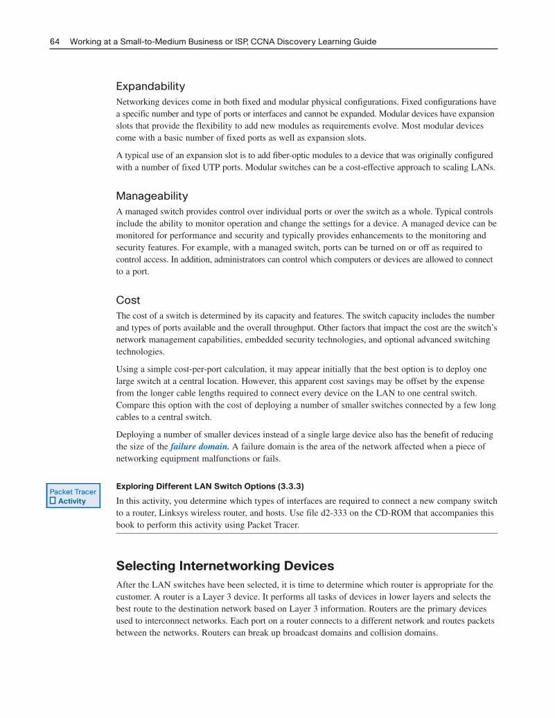
Network Equipment UpgradesMany small networks were initially built using a low-end integrated router to connect wireless andwired users. This type of device is designed to support small networks, usually consisting of a few wiredhosts and possibly four or five wireless devices. When a small business outgrows the capabilities of itsexisting network devices, it must upgrade to more-capable devices. The devices used in this courseand book are the Cisco 1841 ISR and the Cisco 2960 switch, as shown in Figure 3-9.
Figure 3-9 Cisco 1841 ISR and 2960 Switch
66 Working at a Small-to-Medium Business or ISP, CCNA Discovery Learning Guide
Packet Tracer Activity
Cisco 1841 ISR
Cisco 2960 Switch
The Cisco 1841 ISR is designed to be a branch office or medium-sized business router. As an entry-level multiservice router, it offers a number of different connectivity options. It is modular in designand can deliver multiple security services.
The Cisco Catalyst 2960 series Intelligent Ethernet switches are a family of fixed-configuration,standalone devices that provide Fast Ethernet and Gigabit Ethernet connectivity to the desktop. Theseswitches can provide the high speeds and high-density switching capabilities that the smaller ISRswith integrated switching cannot. They are therefore a good option when upgrading networks builtwith either hubs or small ISR devices.
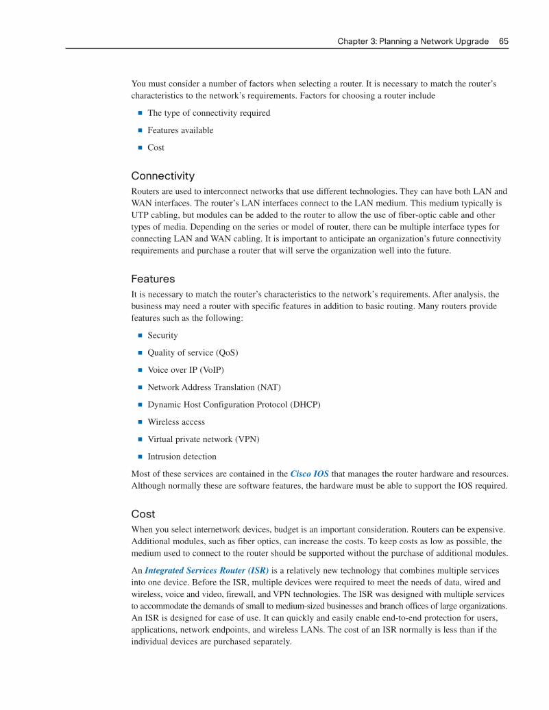
The Catalyst 2960 family of switches, shown in Figure 3-10, provides entry-level, enterprise-class,fixed-configuration switching that is optimized for access layer deployments. They provide both FastEthernet and Gigabit Ethernet to the desktop and are ideal for entry-level enterprise, mid-market, andbranch-office environments. These compact switches often are deployed outside the wiring closet.
04_2109_ch03.qxd 4/8/08 3:31 PM Page 66
Figure 3-10 Cisco Catalyst 2960 Family of Switches
Chapter 3: Planning a Network Upgrade 67
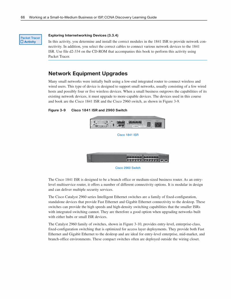
A failure of any of theseswitches affects only thedirectly connected PCs.
The failure of either one of these central switches does not stop network operation.
Reliability and AvailabilityPurchasing network devices and the installation of cabling for a network upgrade is only the begin-ning. Networks must be both reliable and available. Reliability is usually achieved by adding redun-dant components to the network, such as two routers instead of one. In this case, alternative data pathsare created, so if one router experiences problems, the data can take an alternative route to arrive atthe destination. For better reliability, all devices and connections should have complete redundancy.Unfortunately, this is extremely expensive in most environments. Therefore, the network design teammust determine the level of redundancy to incorporate to achieve the necessary reliability. Figure 3-11shows redundancy in a switched network.
Figure 3-11 Redundancy in a Switched Network
04_2109_ch03.qxd 4/8/08 3:31 PM Page 67
Availability is the amount of time the network is ready and able to deliver the necessary services. Anyincrease in reliability improves availability. Ensuring a higher level of availability requires not onlyredundancy but also equipment and software that have been engineered to provide this level of serv-ice. As an example of availability, telephone systems require “five 9s” of uptime. This means that thetelephone system must be available 99.999% of the time. Telephone systems cannot be down, orunavailable, more than .001% of the time.
Fault tolerance systems typically are used to improve network reliability. Fault tolerance systemsinclude devices such as UPSs, multiple AC power supplies, hot-swappable devices, and multiple inter-face cards. When one device fails, the redundant or backup system takes over to ensure minimal lossof reliability.
IP Addressing PlanPlanning for the network installation must include planning the logical addressing. Changing theLayer 3 IP addressing is a major issue when upgrading a network. If the network’s structure ischanged in the upgrade, the IP address scheme and network information may need to be altered toreflect the new structure.
When developing the addressing scheme, you must consider every device that requires an IP address,now and in the future. Some devices require addresses to carry out their functionality, and others onlyrequire an IP address to allow them to be accessed and configured across the network. Hosts and net-work devices that require an IP address include
■ User computers
■ Administrator computers
■ Servers
■ Other end devices such as printers, IP phones, and IP cameras
■ Router LAN interfaces
■ Router WAN (serial) interfaces
■ Standalone switches
■ Wireless access points
For example, if a new router is introduced to the network, new local networks, or subnets, are created.These new subnets need to have the proper IP address and subnet mask calculated. Sometimes, thismeans having to assign a totally new addressing scheme to the entire network.
After all the planning and design phases are complete, the upgrade proceeds to the implementationphase, in which the actual network installation begins.
68 Working at a Small-to-Medium Business or ISP, CCNA Discovery Learning Guide
04_2109_ch03.qxd 4/8/08 3:31 PM Page 68

Chapter 3: Planning a Network Upgrade 69
SummaryNetworks often experience unexpected growth and develop in a disorganized manner. When this hap-pens, network performance degrades slowly with each new device added. At some point, the networkno longer can support the traffic being generated by the users, so a network upgrade is required.
Whether the network upgrade is forced or planned, the upgrade process must be conducted in anorganized manner. The upgrade plan must consider the strengths and weaknesses of and opportunitiesand threats posed by the network installation.
A network upgrade has five phases:
■ Requirements gathering
■ Equipment selection and network design
■ Implementation
■ Operation
■ Review and evaluation
Documentation must include the physical and logical topology of the existing network, along with acomplete inventory sheet of all equipment. This includes the location and layout of any telecommuni-cations rooms as well as existing network wiring. Customer network requirements are gatheredthrough surveys and interviews.
Cabling has four physical areas to consider: work areas, distribution area, telecommunications room,and backbone. Structured cabling projects deal with the placement of cables, the location of wiringclosets, cable management, and electrical considerations.
When new equipment is used in a network upgrade, you have two purchase options: managed serviceand in-house. Both of these present many advantages and have serious limitations. The choicedepends on the current business strengths and weaknesses.
Cost and expandability are two of the most important considerations when upgrading network devices.Generally, a device that functions at a higher OSI layer is considered a more intelligent device.
Activities and LabsThis summary outlines the activities and labs you can perform to help reinforce important conceptsdescribed in this chapter. You can find the activity and Packet Tracer files on the CD-ROM accompanyingthis book. The complete hands-on labs appear in Part II.
Interactive Activity on the CD:
Interactive Activity 3-1: Network Planning Phases (3.2.1)
Packet Tracer Activities on the CD:
Creating Network Diagrams (3.1.3)
Exploring Different LAN Switch Options (3.3.3)
Exploring Internetworking Devices (3.3.4)
Packet Tracer Activity
04_2109_ch03.qxd 4/8/08 3:31 PM Page 69

70 Working at a Small-to-Medium Business or ISP, CCNA Discovery Learning Guide
Hands-on Lab in Part II of this book:
Lab 3-1: Evaluating a Cabling Upgrade Plan (3.2.4)
Check Your UnderstandingComplete the review questions to check your understanding of the topics and concepts in this chapter.Answers are listed in Appendix A, “Check Your Understanding and Challenge Questions Answer Key.”
1. What is the purpose of a site survey? (Select all that apply.)
A. To determine what network resources are currently in place.
B. To accurately forecast the current and future network requirements.
C. To repair any malfunctioning network equipment.
D. To ensure that all purchased networking equipment is still properly installed and functioning.
2. What should a site survey technician do if he or she finds nonstandard network installations during the survey process?
A. Report the condition to management to make sure that the previous contractor does not getrehired.
B. Inform management that they are in violation of standards and must pay you to correct the situation, or you will have to report them.
C. Ignore the situation, and proceed with the survey.
D. Report the condition to management, pointing out that this often happens when networks growunexpectedly.
3. What should be done as a first step after the technician completes the site survey?
A. Use the information contained in the site survey documents to determine the customer’s net-work requirements.
B. Review the site survey with the customer to make sure that nothing has been missed andeverything is accurate.
C. Use the information contained in the site survey documents to determine how long the plannednetwork upgrade will take.
D. Ask the technician to summarize the site survey documentation, summarizing only the important facts.
4. What should be contained on a logical topology diagram? (Select all that apply.)
A. Location of all networking devices
B. Physical location of cabling runs
C. IP address information of all devices
D. Device names
E. Location of wiring closets
04_2109_ch03.qxd 4/8/08 3:31 PM Page 70

Chapter 3: Planning a Network Upgrade 71
5. What information should you record about devices when performing a network inventory? (Select all that apply.)
A. Device name, brand, and model
B. Physical location
C. Operating system
D. Logical addressing information
E. Connection information
F. Security information
6. What is the correct sequence of steps when performing a network upgrade?
1. Review and evaluation
2. Implementation
3. Operation
4. Requirements gathering
5. Selection and design
A. 1, 2, 3, 4, 5
B. 4, 5, 1, 2, 3
C. 4, 5, 2, 3, 1
D. 4, 1, 5, 3, 2
E. 1, 4, 5, 2, 3
7. What is the name of the location where all network cable is concentrated in a single point?
A. IDF
B. ISP
C. IXP
D. MDF
E. MFD
8. What type of cable typically is used to connect a workstation network interface card (NIC) to thewall outlet?
A. STP
B. UTP
C. Coaxial
D. Fiber-optic
9. Which of the following direct connections normally would require a crossover cable? (Select allthat apply.)
A. A PC connected to another PC
B. A PC connected to a switch
C. A PC connected to a router
D. A switch connected to a router
E. A router connected to another router
10. What factors should you consider when selecting an internetworking device?
04_2109_ch03.qxd 4/8/08 3:31 PM Page 71

72 Working at a Small-to-Medium Business or ISP, CCNA Discovery Learning Guide
Challenge Questions and ActivitiesThese questions require a deeper application of the concepts covered in this chapter. You can find theanswers in Appendix A.
1. A small company is trying to decide if it should install and manage its own network solution or ifit should invest in a managed solution from its local ISP. The company currently is having financialdifficulties and does not have an internal IT department. What suggestion would you make, and why?
2. You have asked two new network technicians to recommend a switch for a new department withinthe company. The department will have 27 users and four networked printers. All devices currentlyconnect at 100 Mbps. The first technician recommends a switch that has 48 10/100-Mbps ports.The second technician recommends a slightly more expensive switch that has 48 10/100/1000-Mbpsports and two fiber-optic uplink ports. Which technician has made the better recommendation,and why?
04_2109_ch03.qxd 4/8/08 3:31 PM Page 72