plant procedures manual - volume 13 package no. 2004-263
TRANSCRIPT
ENERGYXNORTHWEST
People *Vision * Solutions
INTEROFFICE MEMORANDUM
DATE: April 22, 2004
TO: Distribution - n
FROMt: Procedure Control, Administrative Services, (901A)
SUBJECT: PLANT PROCEDURES MANUAL - VOLUME 13PACKAGE NO. 2004-263
REFERENCE:The following Procedure(s) have been revised/approved and are to be inserted in your controlled copy ofthe Manual and the superseded revisions are to be removed and destroyed:
13.8.1 25 EMERGENCY DOSE PROJECTION SYSTEM OPERATIONS13.10.3 20 TECHNICAL MANGER AND STAFF DUTIES13.10.4 28 RADIATION PROTECTION MANAGER DUTIES13.10.7 21 PLANT ADMINISTRATIVE MANAGER DUTIES13.11.3 23 SITE SUPPORT MANAGER AND STAFF DUTIES13.11.7 28 RADIOLOGICAL EMERGENCY MANGER DUTIES
Also included in this package are EDITORIAL CHANGES, please replace pages located in yourmanual with the attached pages:
Procedure Rev Title/Comments
13.12.20 4 16
To verify receipt or cancellation of the subject Procedure(s), please sign, date and return this receiptto Procedure Control, MD 901A within TEN (10) WORKING DAYS of the date of this IOM.
Energy NorthwestProcedure Control (Mail Drop 901A)
PO Box 968Richland, WA 99352
Date Signature of Manual Holder Controlled Copy Number
A-oY5
1 III III IIIITII III 11*13.8.1*
ENERGY USE CURRENT REVISION
NORTHWESTPeople *Vision* Solutions
COLUMBIA GENERATING STATION
PLANT PROCEDURES MANUAL
PROCEDURE NUMBER APPROVED BY DATE
*13.8.1 SLS - Revision 25 04/22/04VOLUME NAME
EMERGENCY PLAN IMPLEMENTING PROCEDURESSECTION
OFFSITE DOSE CALCULATIONSTITLE
EMERGENCY DOSE PROJECTION SYSTEM OPERATIONS
TABLE OF CONTENTS
1.0 PURPOSE ...................
2.0 REFERENCES ................
3.0 DEFINITIONS ................
4.0 PROCEDURE ................
4.1 General Instructions ........4.2 Dose Estimation Using QEDPS .4.3 Dose Estimation Using EDPS . .4.4 Historical Dose Projections ...
5.0 ATTACHMENTS ..............
5.1 EDPS User Guidance .......
Page
. 2
. 2
. 2
. 4
. 4.5
. 7.8
.9
10
PROCEDURE NUMBER REVISION PAGE
13.8.1 25 1 of 23
1.0 PURPOSE
This procedure provides instructions for the use of the computerized Emergency DoseProjection System (EDPS) to predict offsite dose rates, integrated doses and radioactivematerial deposition for locations within the 10-mile Plume Emergency Planning Zone (EPZ)and the 50-mile Ingestion EPZ. Actual manipulation of system display terminals is describedin the Emergency Dose Projection System Users Manual referred to as the Users Manual.
{R1594}
2.0 REFERENCES
2.1 10 CFR 50 .47(b) {R1594}
2.2 GI2-03-020, Elimination of Requirements for Post Accident Sampling System{C-1 1714}
2.3 Emergency Dose Projection System Users Manual
2.4 FSAR, Chapter 13.3, Emergency Plan, Section 5.3
2.5 NUREG 1228, Source Term Estimation During Incident Response to Severe NuclearPower Plant Accidents
2.6 PPM 13.1.1, Classifying the Emergency
2.7 PPM 13.2.1, Emergency Exposure Levels/Protective Action Guides
2.8 PPM 13.2.2, Determining Protective Action Recommendations
3.0 DEFINITIONS
3.1 Contours - Lines on the output map(s) connecting points of equal dose/doserate/deposition.
3.2 Delta T - The temperature difference between two sensors located at different elevationson a meteorological tower.
3.3 EDPS (Puff) - A dose projection computer program which employs all the designcapabilities of multi-meteorology station data, variable source term via iterative dataentry, full release time specification and a full output map selection. EDPS will computedose/dose rate/deposition based on effluent monitor releases or reactor conditions out to50 miles. EDPS provides the opportunity to modify the source term, reactor power, andrelease rates. EDPS will accept data from up to 50 meteorology stations to morerealistically model the radioactive release via the puff dispersion model.
PROCEDURE NUMBER REVISION PAGE
13.8.1 25 2 of 23
3.4 EDPS (Plume) - The EDPS Plume model accepts only a constant wind speed, directionand stability class from Columbia Generating Station per release. Additional data areignored. Otherwise, EDPS (Plume) has similar capabilities as EPDS (Puff) model does.
3.5 Grid Points - EDPS calculations are based on two grid coordinate systems, both centeredon the reactor building. For the polar grid, doses are calculated at 10 degree intervals on6 concentric circles around the reactor. For the Cartesian grid, doses are calculated at961 uniformly-spaced locations on the model domain (0-10 or 0-50 miles).
3.6 OEDPS - Quick EDPS is a fully defaulted, single entry screen EDPS subprogramdesigned for quick execution during the early stage of the plume phase and for EALcalculations. Many of the input options are defaulted with text and map output available.QEDPS uses plant monitor data or field team data to calculate offsite doses.
3.7 Release Height - The assumed calculation release height. The effective release height isground-level which is indicated in EDPS by entering 1 meter (or foot).
3.8 Source Term - The quantity and radionuclide makeup of the material in the release. Thesource term used in EDPS is based on NUREG-1228.
3.9 Stability Class - Values from A to G representing ranges of Delta T which in turnrepresent atmospheric mixing estimations. The NRC definitions of these ranges are usedto define the stability classes used in EDPS.
3.10 Radioactive Release - A radioactive release is in progress when effluent monitors indicatean increase in radiation levels from normal readings for plant operating conditions orwhen field teams detect environmental radiation 10 times greater than normalbackground, AND the increased levels are attributable to the emergency event.
3.11 Radioactive Release Termination - A radioactive release is terminated when the followingcriteria have been met:
1. The source of the release has been isolated;2. The effluent monitors are trending downward;3. The Environmental Field Teams can no longer track the plume.
PROCEDURE NUMBER REVISION PAGE
13.8.1 25 3 of 23
4.0 PROCEDURE
4.1 General Instructions
1. If in a declared emergency and an offsite dose or dose rate projection is needed,or if so directed, operate QEDPS or EDPS.
2. If necessary, boot up the PC at the work station. Log onto the LAN using youruser ID and password:
NOTE: The PC assigned to the DOE representative at the JIC may be relocatedto the Alternate EOF and used for dose projections. If relocated, it must beconnected to the LAN to access PDIS.
3. Start PDIS by double-clicking on the appropriate PDIS icon on the Windowsdesktop. Minimize PDIS, and start QEDPS or EDPS.
* When both programs are running, window back and forth for dataselection and dose projection input.
4. Access the Rad Status screen by pulling down the EOP menu from the PDISmenu bar. Select Rad Status to obtain key radiation monitor data,meteorological, and effluent data.
* Other PDIS pulldown menus may be selected to view other plantparameters or trends as desired.
5. Use either the QEDPS or EDPS based on the following considerations:
a. In the Control Room and TSC, use QEDPS to estimate doses.
b. In the EOF dose assessment area:
1) Use QEDPS to estimate initial offsite doses when plantmonitoring data are available.
2) Use QEDPS to estimate offsite doses during quickly changingmeteorology or release conditions.
3) When sufficient dose assessment staff are available, then theEDPS may be run along with QEDPS. EDPS results may belower because of additional parameters supplied when enteringEDPS data.
PROCEDURE NUMBER REVISION PAGE
13.8.1 25 4 of 23
4) Once the release has stabilized or is decreasing, then sole use ofEDPS is appropriate with constant meteorological conditions.
5) Use of the EDPS Puff model at the end of the Early (plume)phase, in the Intermediate phase, or with variable meteorologicalconditions, is appropriate.
6. Refer to Attachment 5.1 as a guide through EDPS. For more detail consult theEDPS Users Manual.
7. Real time radiological and meteorological data is used by QEDPS and EPDS bydefault. Historical dose projections are estimated in Section 4.5.
8. Review dose projection printouts, note any qualifying factors, as appropriate,initial for release and brief the RPM or REM, as appropriate, on the doseprojection.
9. Refer to PPM 13.2.2 for Protective Action Recommendation (PAR) guidelines.
4.2 Dose Estimation Using OEDPS {C-1 1714}
1. Verify that system is operational by turning on the surge protector, CPU,monitor, and printer, if necessary.
NOTE: In the event of a loss of SM-7, power to the stack monitor chiller unitsis lost and causes the stack monitors to be out of service. If there is a loss ofSM-7, verification of an offsite release from the reactor building must beconfirmed by the Environmental Field Teams.
2. Activate QEDPS by double clicking the QEDPS icon.
a. The Monitoring/Field Data screen lists the Plant Monitors and FieldTeam options used to calculate a release. Readings for all monitorslisted are normally available on the Rad Status screen in PDIS for use inthe TSC or EOF.
b. Select monitor to be used for the calculations from Columbia GeneratingStation and enter data in appropriate blocks.
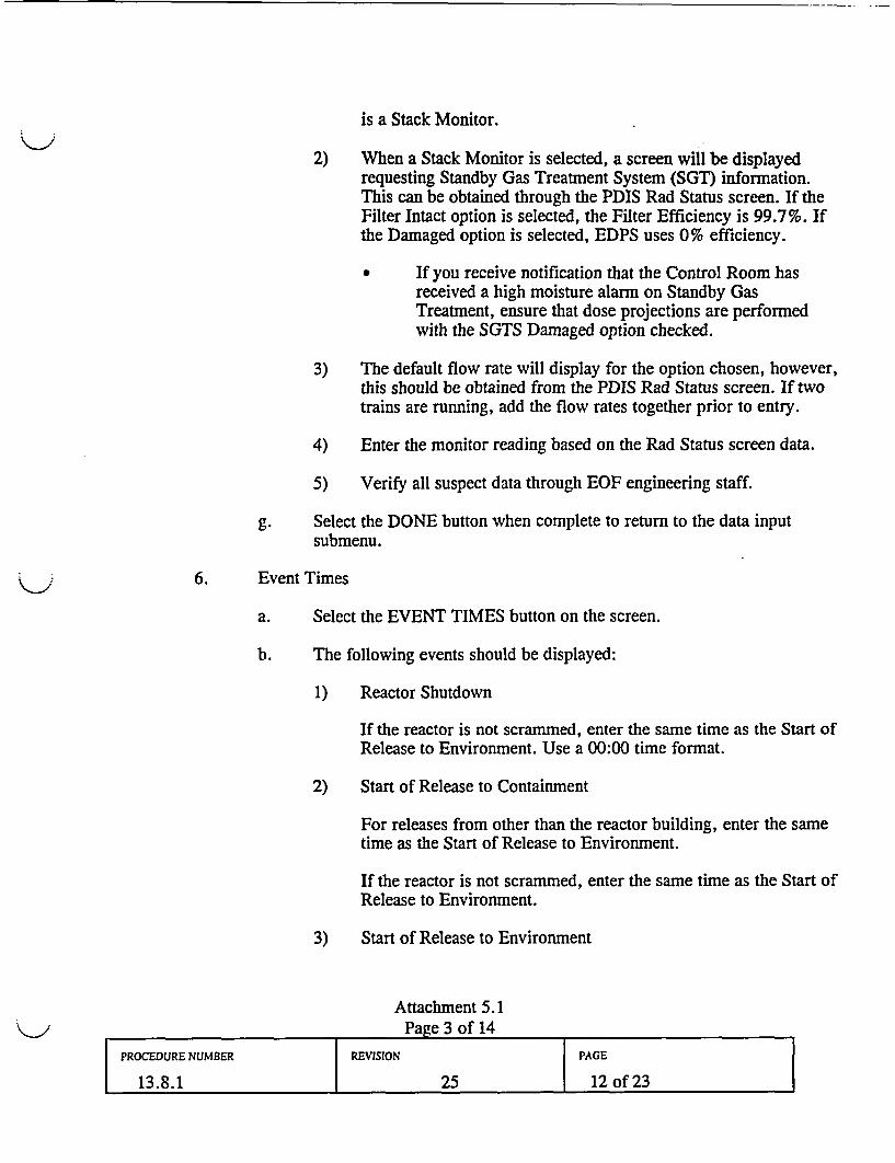
1) If the release path is out the Reactor Building, the primary choiceis a Stack Monitor.
2) When a Stack Monitor is selected, a screen will be displayedrequesting Standby Gas Treatment System (SGT) information.
* If you receive notification that the Control Room has
PROCEDURE NUMBER REVISION PAGE
13.8.1 25 5 of 23
received a high moisture alarm on Standby GasTreatment, ensure that dose projections are performedwith the SGTS Damaged option checked.
3) The default flow rate will display for the option chosen. Actualvalues will need to be entered. If two trains of SGT are running,enter the total for both trains.
4) Enter the monitor reading.
5) In the EOF, all suspect data should be verified through EOFengineering staff.
c. Dose Estimation for Unmonitored Release Paths or if Instrumentation isOut of Service or Offscale.
1) Obtain field team data in the form of iodine air sample results ordose rates from the Field Team Coordinator.
2) On the Windows Desktop, select the Excel air sample iconcorresponding to the units of the air sample.
3) Enter the cartridge and background readings, and press the tabkey to perform the calculation.
4) Select field team data type from the QEDPS menu and enter fieldteam sample results or dose rate values in the popup whenprompted.
5) Use closed window readings when calculating dose projectionsusing field team dose rate meter data.
3. Projected Release Duration
a. If End of Release is not known, a default value of the time of the releaserounded up to the next hour plus two hours should be used.
EXAMPLE: Release has lasted for 25 minutes. Round 25 minutes upto 1 hour and add 2 hours to give a release duration of 3 hours.
b. Time since Reactor Shutdown
If the reactor is not scrammed, leave the value set to zero.
4. Enter Meteorology information. Stability class is entered as an alpha character
PROCEDURE NUMBER REVISION PAGE
13.8.1 25 6 of 23
A-G. Meteorological parameters from the primary met tower are normallyavailable on the Radiological Parameters screen. If the primary met towerparameters are not available, use instructions in Attachment 5.1, step 2.2.4.k.3.
5. Select RUN to calculate doses.
6. Select PRINT to produce a paper output with emergency worker doseadjustment factor included.
7. Click on MAP to produce a projected plume map with TEDE and thyroid CDEvalues. If another dose projection is desired, click on RETURN.
NOTE: When returning from the Centerline Dose Results table, you mayarchive the results by clicking Yes when prompted. Results are archived in afile called Qarchive found in the subdirectory called Output, which is a part ofthe subdirectory QEDPS. Results are appended to the existing file and can beviewed with any text editor.
8. Compare doses and dose rates at 1.2 and 10 miles with EALs (PPM 13.1.1Table 4) and protective action guidelines (PPM 13.2.1).
9. To perform another dose calculation, click on RETURN. Previous entries areretained. Enter the new values and select RUN.
10. Label and sign printed data for distribution. Forward to the REM for approvalduring the plume phase. In the Control Room the Shift Manager has approvalauthority. The Washington Senior State Official approves release data fordistribution during the ingestion phase. Maintain a binder of all originalprintouts.
11. When finished in QEDPS, select QUIT.
4.3 Dose Estimation Using EDPS
1. Verify that the system is operational by turning on the surge protector, CPU,monitor, and printer, as necessary.
2. Activate EDPS by double-clicking on the EDPS icon.
3. Starting at the bottom of the Log On screen, enter your name and click on yourlocation, then exit this screen via the OK button. These actions will identifyyour model outputs.
4. An understanding of the following is necessary to successfully execute theprograms:
PROCEDURE NUMBER REVISION PAGE
13.8.1 25 7 of 23
a. At several points in the program when a subprogram begins execution, ablack window appears. Press Enter (Return) and, if necessary, click onthe X in the upper right to continue.
b. Use the reactor power level default value of 100% unless the reactor hasbeen operating at a different power level for some time. Radioactivedecay correction of the source term depends on the interval betweenReactor Shutdown Time and Start of Release to Environment, which areentered on the EVENT TIMES screen.
c. Ensure that the plant is the first weather station selected in themeteorology module and that data are entered. The PLUME modelrequires input from only one set of meteorological data from the plant.
d. If the meteorology data times entered do not occur prior to or the sameas the Start of Release to Environment, then you will get zero dose onyour map contours window (ZMAX=0).
e. Maps and text output may be made for any 15-minute time interval(display time) in the exposure period.
f. If you get a page fault or any other error message, go back to the mainscreen and click on FILES then NEXT RUN to restart at the beginningof data input.
4.4 Historical Dose Projections
I1. Contact the PDIS Analyst in the EOF to obtain historical values for thefollowing computer points if the release is from the Reactor Building:
X406, Low Range Stack Monitor, PRM-RE-1AX407, Intermediate Range Stack Monitor, PRM-RE-lBX392, High Range Stack Monitor, PRM-RE-1CF146, Delta TF145, Wind direction at 33'F144, Wind speed at 33'
Contact the PDIS Analyst to obtain additional values as necessary:X198, Turbine Building Exhaust FlowX409, Turbine Building Low Range MonitorX394, Turbine Building Intermediate Range MonitorX366, Radwaste Building Exhaust FlowX408, Radwaste Building Low Range MonitorX393, Radwaste Intermediate Range MonitorX466, SGTS Al
PROCEDURE NUMBER REVISION PAGE
13.8.1 25 8 of 23
X356, SGTS A2X452, SGTS BIX371, SGTS B2
2. Enter the appropriate values and click RUN, PRINT or MAP as instructed.
5.0 ATTACHMENTS
5.1 EDPS User Guidance
PROCEDURE NUMBER REVISION PAGE
13.8.1 25 9 of 23
EDPS USER GUIDANCE
1.0 DATA ENTRY OVERVIEW
1.1 The EDPS Main Window provides a snapshot of the flow of data required to generate adose projection.
1.2 An arrow points toward the module(s) that are available for data entry.
1.3 As information is entered into the various modules, a check mark will display next to thecompleted module.
1.4 The EDPS system will highlight the normal sequence throughout the program by puttinga small box around the current field requiring a response.
1.5 Use of the Tab key is the recommended method for entering numerical data.
1.6 Use of the left mouse button is the recommended method for navigation through theprogram.
2.0 DATA ENTRY
2.1 Input Source Term Data
1. At the "Logon as EDPS Master Terminal" screen:
a. Select location for performing a dose projection.
b. Enter your name and select "OK" to continue.
2. At the EDPS Main Window screen, select "Files" and "Next Run" to reset theprogram.
3. Select Scenario Description on the EDPS Main window to begin entering data.
4. Title/Model/Height/Power
a. Select the Title/Height/Bldg Wake/Power submenu.
b. Type in a Run Title for the dose projection being performed. Example:Run 1
Attachment 5.1Page 1 of 14
PROCEDURE NUMBER REVISION PAGE
13.8.1 25 10 of 23
c. Choose the desired Transport Model. In general:
1) For most projections, select the Puff model.
* The Plume model should be selected if the projection isfor a near site vicinity map.
2) In the Intermediate (Ingestion) Phase, use the Puff Model
d. Choose Wake Effects or No Wake Effects.
The building wake option should be selected to allow building wake tobe accounted for in the rate of diffusion.
e. Enter 1 meter as Effective Release Height.
f. Enter the Reactor Power level at which the plant was operating prior toshutdown. The default value is 100%. If the plant was shutdown forseven days or longer, use 0% for power.
g. When the above data are entered, select the DONE button on the screen.
5. Source Term
a. Select the Source Term submenu.
b. Select the Source Term option from the display which will be used toperform the projection.
c. When plant monitoring data are available, Monitoring Data is thedesired option.
d. If the effluent monitors are out of service, refer to Section 4.0 of thisattachment for dose calculations based on plant conditions or sampleanalysis. QEDPS should also be used to complete the dose projectionsbased on field team results.
e. The Monitoring Data screen lists the Plant Monitors used to calculate arelease. Readings for all monitors listed are normally available on theRad Status screen in PDIS.
f. Select monitor to be used for the calculation and enter data inappropriate blocks.
1) If the release path is out the Reactor Building, the primary choice
Attachment 5.1Page 2 of 14
PROCEDURE NUMBER REVISION PAGE
13.8.1 25 11 of 23
is a Stack Monitor.
2) When a Stack Monitor is selected, a screen will be displayedrequesting Standby Gas Treatment System (SGT) information.This can be obtained through the PDIS Rad Status screen. If theFilter Intact option is selected, the Filter Efficiency is 99.7%. Ifthe Damaged option is selected, EDPS uses 0% efficiency.
If you receive notification that the Control Room hasreceived a high moisture alarm on Standby GasTreatment, ensure that dose projections are performedwith the SGTS Damaged option checked.
3) The default flow rate will display for the option chosen, however,this should be obtained from the PDIS Rad Status screen. If twotrains are running, add the flow rates together prior to entry.
4) Enter the monitor reading based on the Rad Status screen data.
5) Verify all suspect data through EOF engineering staff.
g. Select the DONE button when complete to return to the data inputsubmenu.
6. Event Times
a. Select the EVENT TIMES button on the screen.
b. The following events should be displayed:
1) Reactor Shutdown
If the reactor is not scrammed, enter the same time as the Start ofRelease to Environment. Use a 00:00 time format.
2) Start of Release to Containment
For releases from other than the reactor building, enter the sametime as the Start of Release to Environment.
If the reactor is not scrammed, enter the same time as the Start ofRelease to Environment.
3) Start of Release to Environment
Attachment 5.1
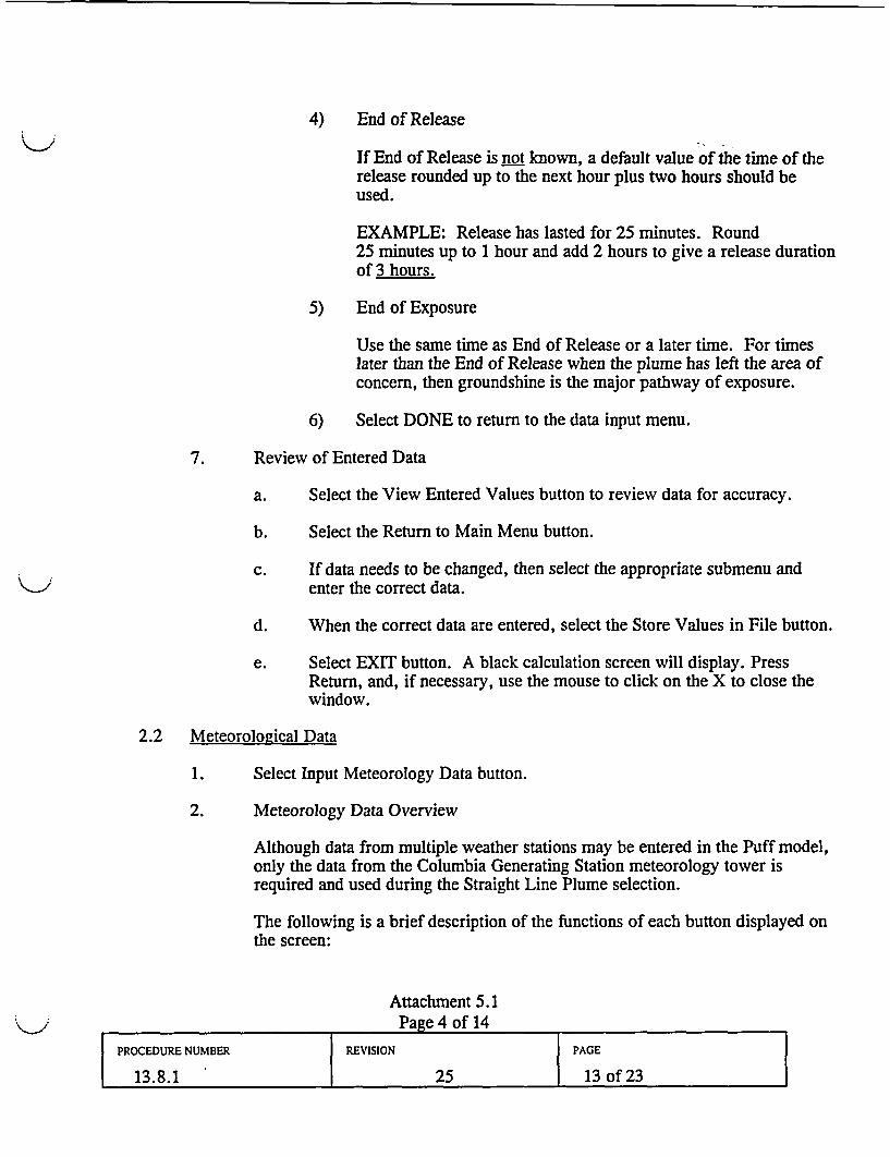
4) End of Release
If End of Release is not known, a default value of the time of therelease rounded up to the next hour plus two hours should beused.
EXAMPLE: Release has lasted for 25 minutes. Round25 minutes up to 1 hour and add 2 hours to give a release durationof 3 hours.
5) End of Exposure
Use the same time as End of Release or a later time. For timeslater than the End of Release when the plume has left the area ofconcern, then groundshine is the major pathway of exposure.
6) Select DONE to return to the data input menu.
7. Review of Entered Data
a. Select the View Entered Values button to review data for accuracy.
b. Select the Return to Main Menu button.
c. If data needs to be changed, then select the appropriate submenu andenter the correct data.
d. When the correct data are entered, select the Store Values in File button.
e. Select EXIT button. A black calculation screen will display. PressReturn, and, if necessary, use the mouse to click on the X to close thewindow.
2.2 Meteorological Data
1. Select Input Meteorology Data button.
2. Meteorology Data Overview
Although data from multiple weather stations may be entered in the Puff model,only the data from the Columbia Generating Station meteorology tower isrequired and used during the Straight Line Plume selection.
The following is a brief description of the functions of each button displayed onthe screen:
Attachment 5.1Page 4 of 14
PROCEDURE NUMBER REVISION PAGE
13.8.1 25 13 of 23
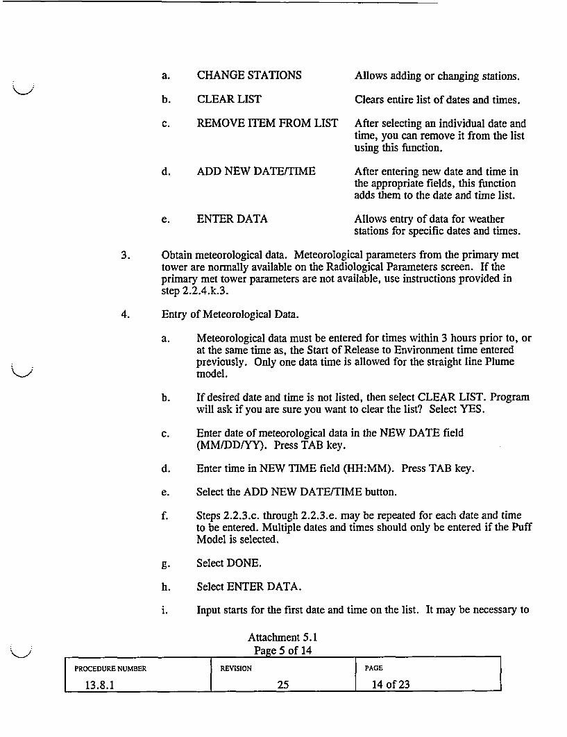
a. CHANGE STATIONS Allows adding or changing stations.
b. CLEAR LIST
c. REMOVE ITEM FROM LIST
d. ADD NEW DATE/TIME
e. ENTER DATA
Clears entire list of dates and times.
After selecting an individual date andtime, you can remove it from the listusing this function.
After entering new date and time inthe appropriate fields, this functionadds them to the date and time list.
Allows entry of data for weatherstations for specific dates and times.
3. Obtain meteorological data. Meteorological parameters from the primary mettower are normally available on the Radiological Parameters screen. If theprimary met tower parameters are not available, use instructions provided instep 2.2.4.k.3.
4. Entry of Meteorological Data.
a. Meteorological data must be entered for times within 3 hours prior to, orat the same time as, the Start of Release to Environment time enteredpreviously. Only one data time is allowed for the straight line Plumemodel.
b. If desired date and time is not listed, then select CLEAR LIST. Programwill ask if you are sure you want to clear the list? Select YES.
c. Enter date of meteorological data in the NEW DATE field(MM/DD/YY). Press TAB key.
d. Enter time in NEW TIME field (HH:MM). Press TAB key.
e. Select the ADD NEW DATE/TIME button.
f. Steps 2.2.3.c. through 2.2.3.e. may be repeated for each date and timeto be entered. Multiple dates and times should only be entered if the PuffModel is selected.
g. Select DONE.
h. Select ENTER DATA.
i. Input starts for the first date and time on the list. It may be necessary to
Attachment 5.1Page 5 of 14
PROCEDURE NUMBER REVISION PAGE
13.8.1 25 14 of 23
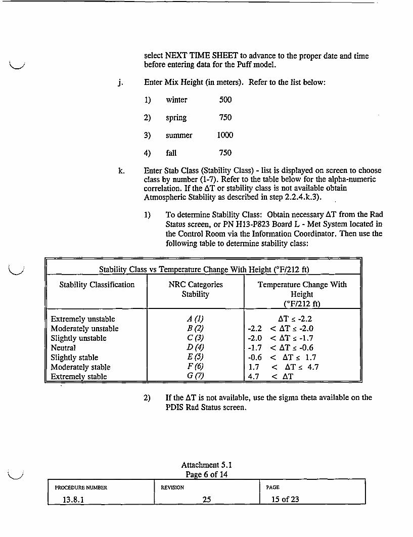
select NEXT TIME SHEET to advance to the proper date and timebefore entering data for the Puff model.
j. Enter Mix Height (in meters). Refer to the list below:
1) winter
2) spring
500
750
10003) summer
4) fall 750
k. Enter Stab Class (Stability Class) - list is displayed on screen to chooseclass by number (1-7). Refer to the table below for the alpha-numericcorrelation. If the AT or stability class is not available obtainAtmospheric Stability as described in step 2.2.4.k.3).
1) To determine Stability Class: Obtain necessary AT from the RadStatus screen, or PN H13-P823 Board L - Met System located inthe Control Room via the Information Coordinator. Then use thefollowing table to determine stability class:
Stability Class vs Temperature Change With Height (°F/212 ft)
Stability Classification NRC Categories Temperature Change WithStability Height
(0F/212 ft)
Extremely unstable A (1) AT • -2.2Moderately unstable B (2) -2.2 < AT • -2.0Slightly unstable C (3) -2.0 < AT • -1.7Neutral D (4) -1.7 < AT • -0.6Slightly stable E (5) -0.6 < AT • 1.7Moderately stable F(6) 1.7 < AT • 4.7Extremely stable G (7) 4.7 < AT
2) If the AT is not available, use the sigma theta available on thePDIS Rad Status screen.
Attachment 5.1Page 6 of 14
PROCEDURE NUMBER REVISION PACE
13.8.1 25 15 of 23
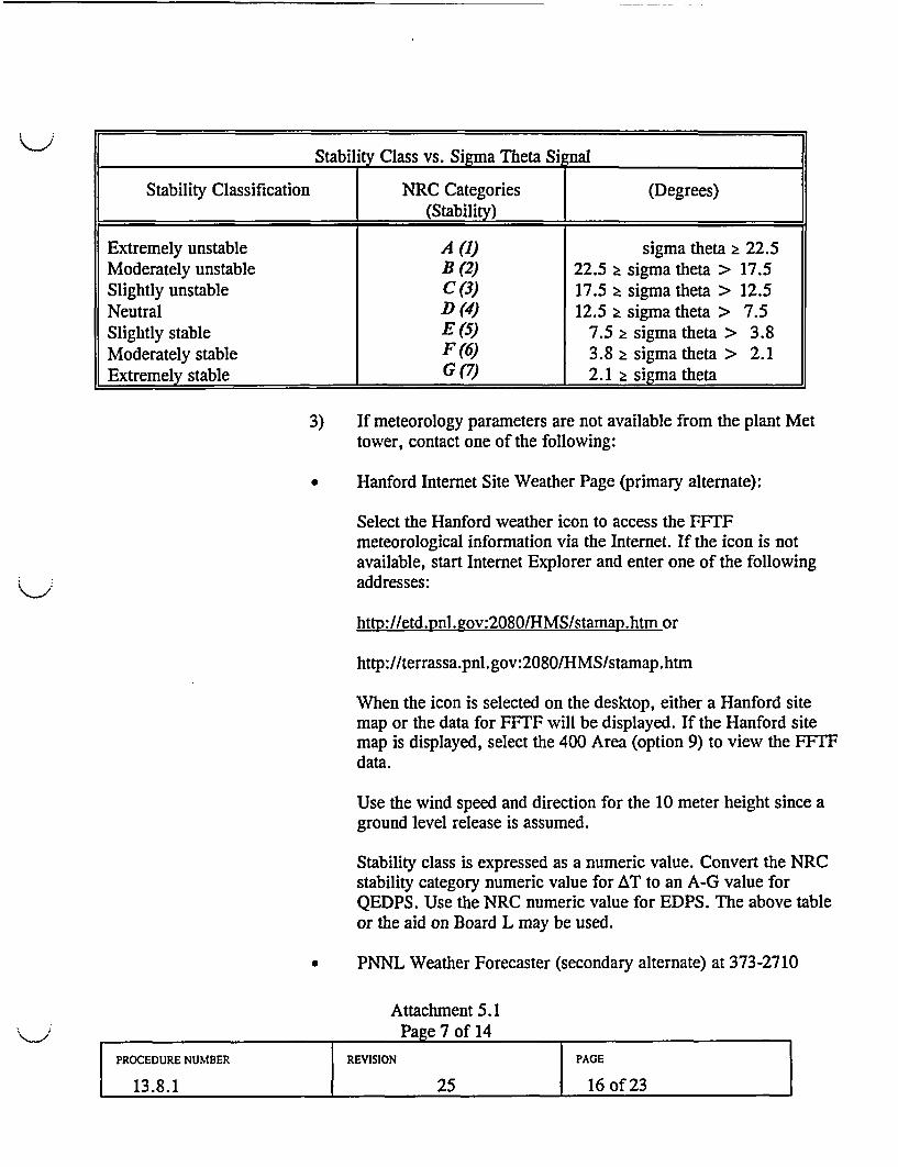
Stability Class vs. Sigma Theta Signal
Stability Classification | NRC Categories (Degrees)l_ (Stability)
Extremely unstable A (1) sigma theta 2 22.5Moderately unstable B (2) 22.5 2 sigma theta > 17.5Slightly unstable C (3) 17.5 2 sigma theta > 12.5Neutral D (4) 12.5 2 sigma theta > 7.5Slightly stable E (5) 7.5 2 sigma theta > 3.8Moderately stable F (6) 3.8 2 sigma theta > 2.1Extremely stable G (7) 2.1 2 sigma theta
3) If meteorology parameters are not available from the plant Mettower, contact one of the following:
* Hanford Internet Site Weather Page (primary alternate):
Select the Hanford weather icon to access the FFTFmeteorological information via the Internet. If the icon is notavailable, start Internet Explorer and enter one of the followingaddresses:
http://etd.pnl.-gov:2080/HMS/stamap.htm or
http://terrassa.pnl .gov:2080/HMS/stamap .htm
When the icon is selected on the desktop, either a Hanford sitemap or the data for FFTF will be displayed. If the Hanford sitemap is displayed, select the 400 Area (option 9) to view the FFTFdata.
Use the wind speed and direction for the 10 meter height since aground level release is assumed.
Stability class is expressed as a numeric value. Convert the NRCstability category numeric value for AT to an A-G value forQEDPS. Use the NRC numeric value for EDPS. The above tableor the aid on Board L may be used.
* PNNL Weather Forecaster (secondary alternate) at 373-2710
Attachment 5.1Page 7 of 14
PROCEDURE NUMBER REVISION PAGE
13.8.1 25 16 of 23
Request wind speed, direction, and differential temperature forthe FFTF met tower. If this information is not available from thePNNL forecaster, contact the National Weather Service.
Telephone the National Weather Service Forecaster (tertiaryalternate) at one of the following locations:
1-541-276-4493 Pendleton, Oregon1-206-526-6083 Seattle, Washington
Request the following met data for the Hanford weather station:Wind speed, wind direction, and atmospheric stability, which youwill need to convert to a NRC stability category of 1-7. Thenumeric stability category is the format that ERDS sends to NRC.The National Weather Service does not provide a temperaturedifferential. The NWS will describe the stability category asneutral, moderately stable, etc.
Wind speed obtained from the NWS is in knots. Convert knots tomiles per hour using the following conversion:1 knot = 1.15 statute mile per hour
1. Wind Dir (Wind Direction) - enter direction from which wind isblowing. Data point is normally available on the PDIS Rad Statusscreen.
m. Wind Spd (Wind Speed) - enter wind speed in miles per hour (mph).Data point is normally available on the PDIS Rad Status screen.
n. Precip (Precipitation) - a list is displayed at left of screen to assist inproper entry. Select the appropriate choice.
o. Select Next Time Sheet button if additional dates and times areavailable. When data for all stations have been entered, program willdisplay a message stating it is complete.
p. After data has been entered, select DONE.
2.3 Select MODEL DOMAIN button on EDPS Main Window
1. During the Plume phase, the 0-10 Mile option should be selected. The 0-50 Mileoption should only be selected if the released material has exceeded 10 miles,based on actual duration of the release.
Attachment 5.1Page 8 of 14
PROCEDURE NUMBER REVISION PAGE
13.8.1 25 17 of 23
2. Select DONE button.
2.4 Process Meteorological Data
1. Select PROCESS METEOROLOGICAL DATA button.
2. A black calculation window will appear behind the menu. Press Return whencalculations are complete and close the window by selecting X if necessary.
3. Press the Enter key to return to the EDPS Main Menu.
2.5 Transport Calculation
1. Select TRANSPORT CALCULATION. This module calculates the dispersionfor each grid point.
2. A black calculation window will appear behind the menu. Press Return whencalculations are complete and close the window by selecting X if necessary.
2.6 Choose CALCULATE DOSES Option
1. Select Calculate Doses.
2. For the Plume transport model, use a Display Time value which is equal orprior to End of Release in order to view plume dose rate data. Use of a DisplayTime after the End of Release will produce dose rates due only to groundshinefrom deposition.
3. For the Puff transport model, the Display Time feature allows the puff to beportrayed on the map and in the tabular output at different stages of itsprogression downwind.
4. Change Display Time, if desired. After reviewing data, select the OK button.
5. A black calculation window will appear behind the menu. Press Return whencalculations are complete and close the window by selecting X if necessary.
3.0 DATA OUTPUT
3.1 The EDPS Main Menu should now have check marks beside all options except VIEWDOSE MAP and VIEW TABULAR OUTPUT.
3.2 Select VIEW TABULAR OUTPUT to view the dose projection data
Attachment 5.1Page 9 of 14
PROCEDURE NUMBER REVISION PAGE
13.8.1 25 18 of 23
1. Compare dose projection data at 1.2 miles with the EALs (PPM 13.1.1 Table4).
2. Compare dose projection data with protective action guidelines (PPM 13.2.2).
3. Print the dose projection data by selecting File on the menu bar. Then, selectPrint, and Complete Document.
4. Program may display a screen concerning Print destination and Port. SelectOK.
5. To exit, select File in menu bar and Exit on the pull down menu.
6. Dose Assessor and REM signatures are required if the printed output is leavingMUDAC during the plume phase. The Washington Senior State Officialapproves data for release during the ingestion phase.
3.3 To enter new values and recalculate, select Files/Next Run.
3.4 Select VIEW DOSE MAP button
1. This module has several options:
a. Files Allows viewing of any map files on the computer.
b. Map Allows selection of the map used for the projection.
c. Dose Allows selection of the type of dose to be mapped.
d. Print Allows map printing.
2. Choose Map.
a. If the Plume model was selected, use only the following:
1) Vicinity map (Straight Line Plume Model)
2) 10 mile map (Straight Line Plume Model)
b. For the Puff model:
NOTE: Do not select Option 5 or 6 if running the Puff model.
1) Use any of the following map options:
1) 10 mile map (B&W)
Attachment 5.1Page 10 of 14
2) 10 mile map (color)3) 50 mile map (B&W)4) 50 mile map (color)
2) If printing the maps, select the black and white maps ONLY.
3. Choose Dose to select the type of dose to display and contour values.
a. Contour options:
1) Clear Map Before Plot (This should normally be checked).
2) Recompute Contours (Choose this if manually entering contourlevels).
3) Manually Enter Contour Levels (You may specify contourvalues, however, default values have been entered).
* To print a map showing a projected Plume boundary of100 micro R, select 1.00 E -04 only.
4) During the ingestion phase, manual contour lines may beentered to project the 500 pR (relocation boundary), 20 AR and0.4 yR (food control boundary). To select the correct value,enter the following:
5e-4 for 500 uR2e-5 for 20 pR4e-7 for 0.4 AR
* Select the ground shine projection option when calculating thefood control and relocation boundaries.
b. In the Plume phase, choose:
1) Total Effective Dose Equivalent (TEDE) (rem).
2) Acute Thyroid Dose CDE (rem).
c. Map displays with contour lines drawn.
1) The value of each contour line is displayed in the upper leftcorner of the map.
Attachment 5.1Page 11 of 14
PROCEDURE NUMBER REVISION PAGE
13.8.1 25 20 of 23
2) The map may be moved on the screen by clicking on a locationon the map with the left mouse button and dragging it. (If mapis dragged towards upper left, the contour values willdisappear.)
4. Map Printing
a. For 10 mile maps:
1) Select Print from menu bar.
2) Select Print map from pull down menu.
3) Enter name of person authorizing release. This will normallybe the REM during the plume phase. The Washington SeniorState Official approves data release during the ingestion phase.
4) Select OK to print map.
5) Computer will display message when printing is complete.
6) Different maps may be drawn and printed by starting atStep 3.4.3 and entering a different selection at 3.4.3.a., andrepeating the steps through 3.4.4.b).
7) To EXIT from Map printing:
* Select Files in menu bar.
* Select Exit on pull down menu.
b. 50 mile maps:
1) Select Print from menu bar.
2) Select Print map from pull down menu.
3) Enter name of person authorizing release. This will normallybe the REM during the plume phase. The Washington SeniorState Official approves data release during the ingestion phase.
4) Select OK to print map.
Attachment 5.1Page 12 of 14
PROCEDURE NUMBER REVISION PAGE
13.8.1 25 21 of 23
5) To EXIT from Map printing:
(1) Select Files in menu bar.
(2) Select Exit on pull down menu.
5. Distribution of Maps and Data
a. Any dose projection maps or data printouts selected for distribution tooffsite agencies shall have REM and Emergency Director review andapproval.
b. Maps selected for distribution should always be accompanied by thedata. This is very important because the plume projected on the map isnot closed and without the data sheet, the plume may be misinterpreted.
4.0 OTHER SOURCE TERM OPTIONS
4.1 Dry Well Leakage/Failure
1. Identify the condition/status for the following parameters and choose theappropriate option:
a. Core Condition
b. Containment Sprays
c. Release Path
d. Dry Well Leak Rate
2. Select DONE button.
4.2 Wet Well Leakage/Failure
1. Identify the condition/status for the following parameters and choose theappropriate option:
a. Core Condition
b. Wet Well
Attachment 5.1Page 13 of 14
PROCEDURE NUMBER REVISION PAGE
13.8.1 25 22 of 23
c. Release Path
d. Wet Well Leak Rate
2. Select DONE button.
4.3 Containment Bypass
1. Identify the condition/status for the following parameters and choose theappropriate option:
a. Core Condition
b. Release Path
c. Leak Rate
2. Select DONE button.
4.4 Gross Reactor Release - Specified Mix
1. Base these entries on approved plant sample analyses.
2. Enter the Gross Release Rate in Ci/sec (or Bq/sec).
3. Enter the specific percentage of the Release for the listed radionuclides.
4. Select DONE button when complete.
4.5 Isotopic Release Rates
1. Base these entries on approved plant sample analyses.
2. This section allows for entry of the Activity Release Rate (Ci/sec or Bq/sec) for50 different isotopes.
3. After entry is complete, select DONE button.
4.6 Return to Section 2.1, Input Source Term Data, of this attachment to continue enteringdata when an additional dose projection calculation is needed.
Attachment 5.1Page 14 of 14
PROCEDURE NUMBER REVISION PAGE
13.8.1 25 23 of 23
lii 13111 11 IIID 11111111111l*13 .10.3*
X ENERGY USECUR__ENTREV_NORTHWEST
People*Vision * Solutions
COLUMBIA GENERATING STATIONPLANT PROCEDURES MANUAL
NUMBER APPROVED BY DATE
*13.10.3 SLS - Revision 20 04/22/04
VOLUME NAME
EMERGENCY PLAN IMPLEMENTING PROCEDURES
SECTION
PLANT EMERGENCY FACILITIES
TITLE
TECHNICAL MANAGER AND STAFF DUTIES
TABLE OF CONTENTS
Page
1.0 PURPOSE ................................... 2
2.0 REFERENCES ................................... 2
3.0 RESPONSIBILITIES ................................... 2
4.0 PROCEDURE ................................... 3
4.1 Technical Manager ................................... 3
5.0 ATTACHMENTS ................................... 8
5.1 TSC Electrical Engineer Duties ................................... 95.2 TSC Mechanical Engineer Duties ................................ 115.3 TSC Core Thermal Engineer Duties ............................... 135.4 TSC Computer Engineer Duties ................................. 16
NUMBER REVISION PAGE
13.10.3 20 lofl17
1.0 PURPOSE
This procedure provides instructions and guidance for activities of the Technical Manager andengineering staff in the Technical Support Center (TSC) during an emergency.
2.0 REFERENCES
2.1 FSAR Chapter 13.3, Emergency Plan, Sections 2 & 3
2.2 OER SIL324R6, BWR Emergency Support Program
2.3 PPM 5.7.1, Severe Accident Guidelines
2.4 Technical Memorandum 2113, Technical Support Guidelines for Electrical Engineer
2.5 Technical Memorandum 2114, Technical Support Guidelines for Technical Manager
2.6 Technical Memorandum 2115, Technical Support Guidelines for Mechanical Engineer
2.7 Technical Memorandum 2116, Technical Support Guidelines for Trending Forecaster
2.8 Technical Memorandum 2117, Technical Support Guidelines for Core ThermalEngineer
2.9 PPM 13.1.1, Classifying the Emergency
2.10 PPM 13.10.6, Plant/NRC Liaison Duties
2.11 PPM 13.13.4, After Action Reporting
2.12 Work Release Order C-0875
2.13 Repair Team Briefing/Debriefing, 25560
2.14 Technical Support Center (TSC) Briefing Guidelines, 25860
3.0 RESPONSIBILITES
The Technical Manager is responsible for overall direction and supervision of the TSCengineering staff in parameter trending, system operational assessment following EOP/ACP,or Severe Accident Guideline (SAG) implementation, and trouble shooting. The manager isalso responsible for coordinating engineering support from the EOF or from assistingcontractor or vendor organizations.
The Technical Manager should structure the engineering staff by recommending a variety ofaccident assessment and evaluation activities that may be undertaken to mitigate emergencyconditions that may include:
NUMBER REVISION PAGE
13.10.3 20 2 of 17
* Evaluation of events which have or are occurring to gain understanding of the event
* Investigation of aspects which are not understood or that deviate from the expected
* Assessment of events or transients which may adversely affect accident mitigationefforts
* Development of plans that involve the analysis of potential system or componentfailures
* Development of contingency plans to manage failures as they occur
* General trending of critical plant parameters, assessment of inoperable systems orcomponents and problem solving
Technical Support Guidelines (TSGs) Technical Memoranda may be used to aid indevelopment of mitigation strategies.
The term mitigation refers to those activities identified by the engineering staff which areintended to mitigate or minimize the consequences of the particular accident and may includecooling the Reactor, maintaining or regaining containment integrity and terminating orreducing any radioactive release to the environment.
The Technical Manager will confer and support mitigation, reentry and recovery efforts withthe TSC Manager, Operations Manager and Maintenance Manager in the TSC and coordinateOSC implementation of mitigation plans via the Maintenance Manager.
4.0 PROCEDURE
4.1 Technical Manager
4.1.1
4.1.2
4.1.3
Upon notification of an Alert, Site Area, or General Emergency, or if sodirected, proceed to the Technical Support Center (TSC).
Obtain an electronic dosimeter and log in on the emergency RWP.
Present your keycard to the TSC cardreader located by the outer hallwayaccess door to establish electronic Personnel Accountability.
NUMBER REVISION PAGE
13.10.3 20 3 of 17
4.1.4 Enter your name on the TSC Accountability Log located on the table justinside the TSC to establish manual Personnel Accountability.
4.1.5 Write your name on the TSC staffing board in the space next to youremergency position.
4.1.6 If you leave the TSC temporarily, inform the TSC Manager of yourdestination and approximate time of return. Note your destination on theTSC Personnel Accountability Log.
4.1.7 Determine if plant computerized system displays are operating and directthe TSC Computer Engineer to activate any that are not.
4.1.8 Assess engineering staffing and augment as necessary. Your minimumstaffing should consist of:
1 Core/Thermal Engineer1 Mechanical Engineer1 Electrical Engineer1 Computer Engineer
Descriptions of staff duties are contained in Attachments 5.1 through 5.4.
4.1.9 Request the assistance of the Plant Administrative Manager if additionalengineering personnel must be contacted.
4.1.10 As engineering staff become available, assign an individual to monitor thecomputerized plant system displays and trend or plot critical plantparameters that you determine are significant to the emergency event.
4.1.11 Evaluate available data related to the event to:
* Determine what has or is happening including its overall effecton plant operations
* Ascertain if the events that have occurred or are occurring arecompletely understood
* Investigate aspects of the event that are not completelyunderstood or that don't make sense
* Identify any anomalies in trends or data and determine theircause
NUMBER REVISION PAGE
13.10.3 20 4 of 17
4.1.12 Based on the evaluation of events:
* Assign available engineers to assess the event in their areas ofexpertise
* Follow implementation of ACPs/EOPs, and SAGs
* Use TSGs to support EOP and SAG implementation asappropriate
* Refer to and implement Technical Memorandum 2114,Technical Support Guideline actions when required
* Monitor transients or evolutions and evaluate their effect onaccident mitigation objectives
* Recommend preventative actions to avoid the anticipatedoccurrence, or
* Recommend contingency actions should the anticipatedoccurrence be unavoidable
* Assess inoperable systems or components crucial to accidentmitigation and determine corrective actions or alternativemethods to restore lost capabilities
* Monitor trends and determine their potential consequences toaccident mitigation objectives
* When in Severe Accident Management conditions or theRecovery phase and when requested by the EOF EngineeringManager, direct the Core/Thermal Engineer to perform a coredamage evaluation using TM 2117.
4.1.13 Remain aware of plant conditions and critical parameters and assignificant changes occur confer with the TSC Operations Manager sotheir impact on Emergency Action Level (EAL) initiating conditionscontained in PPM 13.1.1 can be assessed.
4.1.14 When the need to re-man Ashe Substation is identified after a siteevacuation, contact the EOF Site Support Manager to determine if theAshe operators are present at the ENOC Offsite Assembly Area. Ifpresent, request their return to the site. Coordinate with Health Physicsfor possible coverage, and with Security for site access.
NUMBER REVISION PAGE
13.10.3 20 5 of 17
4.1.15 If the Ashe operators are not present at the Offsite Assembly Area, directthe EOF Site Support Manager to contact the Dittmer Control Center andrequest that a team be assembled to respond to the site. The team shouldbe directed to report to the Offsite Assembly Area to arrange for HPcoverage if needed for the return to the site, to receive a briefing of theevent, and identify safe access routes.
4.1.16 With your staff, evaluate plant situations collectively and provide accidentmitigation conclusions and recommendations promptly for discussionjointly with the TSC Manager, Operations Manager and MaintenanceManager to determine:.
* Preventative or corrective action tasks that need to be pursued ormay be deferred
* Priority to be assigned tasks that need to be pursued
* Impact the prioritized task may have on other tasks beingperformed
* Need for an engineering staff member to accompany and advisethe OSC team performing the task
4.1.17 Caution your staff to take the most recent plant design modifications intoaccount when evaluating mitigation actions and identifying tasks.
4.1.18 When tasks are selected, assist the Maintenance Manager with outliningtask descriptions and special work instructions or procedure requirementsthat will need to be transmitted to the OSC Manager for taskimplementation.
4.1.19 Monitor the Team Tracking board to observe team progress on tasksselected, or review completed Repair Team Briefing/Debriefing(Form 25560) received by the Maintenance Manager from the OSC.
4.1.20 Determine if EOF engineering assistance may be required and coordinatethat support with the EOF Engineering Manager.
4.1.21 Periodically inform the EOF Engineering Manager of TSC prioritizedactions.
NUMBER REVISION PAGE
13.10.3 20 6 of 17
4.1.22 If General Electric (GE) emergency support is required under provisionsof Energy Northwest contract work release order No. C-0875, determinethe extent of support to be requested such as:
a. Dedicated telephone communications with the GE TechnicalSupport Center in San Jose.
b. Dispatch local GE service personnel to the site (TSC or EOF) toestablish dedicated telephone communications with San Jose.
c. Dispatch a GE team of technical personnel to the site (TSC orEOF). A 24 hour response time is anticipated.
4.1.23 Once the extent of GE emergency support has been identified:
a. Contact the EOF Engineering Manager and request that GE benotified of the need for their services.
b. Brief the TSC Manager and TSC staff on the arrangements madefor GE response.
4.1.24 If contractor or vendor assistance is required coordinate response with theSite Support Manager in the EOF for logistical and point of controlarrangements.
4.1.25 If prolonged operations for the emergency are anticipated, determinerelief shift staffing from the Emergency Response Organization (ERO)list in the Emergency Telephone Directory and coordinate call out withthe Plant Administrative Manager.
4.1.26 Coordinate site departure of relieved personnel in accordance with normalor evacuation instructions that are in effect at the time.
4.1.27 Continuously reevaluate priorities for the engineering staff and redirectthe staff's effort as necessary.
4.1.28 As required, provide technical and engineering expertise for response toinquiries from regulatory agencies.
4.1.29 Monitor, and have your staff monitor, updates to the plant status boardsin the TSC for timeliness and accuracy and offer corrections whereneeded.
4.1.30 When requested, conduct TSC briefings of technical and engineeringactivities. Refer to the Technical Manager's portion of the TechnicalSupport Center (TSC) Briefing Guidelines (25860) located in the TSC.
4.1.31 Upon shift change brief your relief on responsibilities, duties, currentstatus of the plant emergency conditions, and status of work beingperformed.
NUMBER REVISION PAGE
13.10.3 20 7 of 17
4.1.32 Upon shift change or termination of the emergency:
a. Prepare an individual After Action Report in accordance withPPM 13.13.4.
b. Collect the individual After Action Reports and attachmentsprepared by your staff.
c. Review the reports and attachments then deliver them to the TSCManager.
5.0 ATTACHMENTS
5.1 TSC Electrical Engineer Duties
5.2 TSC Mechanical Engineer Duties
5.3 TSC Core Thermal Engineer Duties
5.4 TSC Computer Engineer Duties
NUMBER REVISION PAGE
13.10.3 20 8 of 17

Duties of: TSC Electrical Engineer
Assignment Location: Technical Support Center (TSC)
Reports to: Technical Manager
Activation Level: Alert or higher classification
Responsibilities:
1. Upon notification of an Alert, Site Area, or General Emergency, or if so directed, proceed tothe Technical Support Center (TSC). Obtain appropriate dosimetry.
2. Present your keycard to the TSC cardreader located by the outer hallway access door toestablish electronic Personnel Accountability.
3. Enter your name on the TSC Accountability Log located on the table just inside the TSC toestablish manual Personnel Accountability.
4. Write your name on the TSC staffing board in the space next to your emergency position.
5. If you leave the TSC temporarily, inform the Technical Manager of your destination andapproximate time of return. Note your destination on the TSC Personnel Accountability Log.
6. Obtain a briefing from the Technical Manager on the status of emergency conditions.
7. Follow EOP/ACP implementation.
8. From TSC status boards, computerized system displays and most recent prints, drawings,technical manuals, vendor literature, etc., evaluate data related to the event and:
* Assess the event in your area of expertise
* Monitor transients or evolutions and evaluate their effect on accident mitigationobjectives
* Recommend preventative actions to avoid the anticipated occurrence
* Recommend contingency action should the anticipated occurrence be unavoidable
* Assess inoperable systems or components crucial to accident mitigation and determinecorrective actions or alternative methods to restore lost capabilities
* Monitor trends and determine their potential consequences to accident mitigationobjectives.
Attachment 5.1Page 1 of 2
NUMBER REVISION PAGE
13.10.3 l 20 9 of 17
9. Use the data to collectively discuss with the TSC Engineering staff conclusions andrecommendations that determine:
* Preventative or corrective action tasks that need to be pursued or may be deferred
* Priority to be assigned tasks that need to be pursued
* Impact the prioritized task may have on other tasks being performed
* Special work instructions, procedure requirements, tools or equipment needed toperform tasks
* Need for an engineering staff member to accompany and advise an OSC team sent toperform the task
10. Monitor the Team Tracking board in the TSC to observe team progress on selected tasks, orreview completed Repair Team Briefing/Debriefing (Form 25560) when they are receivedfrom the OSC.
11. Provide input for development and review of proposed recovery actions and assist withdevelopment of special procedures that may be required.
12. Implement the actions of Technical Memorandum 2113, Technical Support Guidelines asapplicable:
Tab 2, System Status EvaluationTab 3, System Dependency Matrix
* Tab 4, Support System Dependency Matrix* Tab 5, Component Cooling Survey
13. Upon shift change brief your relief on responsibilities, duties, current status of plantemergency conditions, and status of work being performed. Provide a phone number whereyou can be reached for questions related to your TSC duties.
14. Upon shift change or termination of the emergency:
a. Prepare an individual After Action Report in accordance with PPM 13.13.4.
b. Attach pertinent logs, notes, etc., to your After Action Report and deliver it to theTechnical Manager.
Attachment 5.1Page 2 of 2
NUMBER REVISION PAGE
13.10.3 20 10 of 17

Duties of: TSC Mechanical Engineer
Assignment Location: Technical Support Center (TSC)
Reports to: Technical Manager
*Activation Level: Alert or higher classification
Responsibilities:
1. Upon notification of an Alert, Site Area, or General Emergency, or if so directed, proceed tothe Technical Support Center (TSC). Obtain appropriate dosimetry.
2. Present your keycard to the TSC cardreader located by the outer hallway access door toestablish electronic Personnel Accountability.
3. Enter your name on the TSC Accountability Log located on the table just inside the TSC toestablish manual Personnel Accountability.
4. Write your name on the TSC staffing board in the space next to your emergency position.
5. If you leave the TSC temporarily, inform the Technical Manager of your destination andapproximate time of return. Note your destination on the TSC Personnel Accountability Log.
6. Obtain a briefing from the Technical Manager on the status of emergency conditions.
7. Follow EOP/ACP implementation.
8. From TSC status boards, computerized system displays and most recent prints, drawings,technical manuals, vendor literature, etc., evaluate data related to the event and:
* Assess the event in your area of expertise
* Monitor transients or evolutions and evaluate their effect on accident mitigationobjectives
* Recommend preventative actions to avoid the anticipated occurrence
* Recommend contingency action should the anticipated occurrence be unavoidable
* Assess inoperable systems or components crucial to accident mitigation and determinecorrective actions or alternative methods to restore lost capabilities
* Monitor trends and determine their potential consequences to accident mitigationobjectives.
Attachment 5.2Page 1 of 2
NUMBER REVISION PAGE
13.10.3 20 11 of 17

9. Use the data to collectively discuss with the TSC Engineering staff conclusions andrecommendations that determine:
* Preventative or corrective action tasks that need to be pursued or may be deferred
* Priority to be assigned tasks that need to be pursued
* Impact the prioritized task may have on other tasks being performed
* Special work instructions, procedure requirements, tools or equipment needed toperform tasks
* Need for an engineering staff member to accompany and advise an OSC team sent toperform the task
10. Monitor the Team Tracking board in the TSC to observe team progress on selected tasks, orreview completed Repair Team Briefing/Debriefing (Form 25560) when they are receivedfrom the OSC.
11. Provide input for development and review of proposed recovery actions and assist withdevelopment of special procedures that may be required.
12. Implement the actions of Technical Memorandum 2115, Technical Support Guidelines asapplicable:
* Tab 2, System Status Evaluation* Tab 3, System Dependency Matrix* Tab 4, Support System Dependency Matrix* Tab 5, Component Cooling Survey
13. Upon shift change brief your relief on responsibilities, duties, current status of plantemergency conditions, and status of work being performed. Provide a phone number whereyou can be reached for questions related to your TSC duties.
14. Upon shift change or termination of the emergency:
a. Prepare an individual After Action Report in accordance with PPM 13.13.4.
b. Attach pertinent logs, notes, etc., to your After Action Report and deliver it to theTechnical Manager.
Attachment 5.2Page 2 of 2
NUMBER REVISION PAGE
13.10.3 20 12 of 17
Duties of: TSC Core Thermal Engineer
Assignment Location: Technical Support Center (TSC)
Reports to: Technical Manager
Activation Level: Alert or higher classification
Responsibilities:
1. Upon notification of an Alert, Site Area, or General Emergency, or if so directed, proceed tothe Technical Support Center (TSC). Obtain appropriate dosimetry.
2. Present your keycard to the TSC cardreader located by the outer hallway access door toestablish electronic Personnel Accountability.
3. Enter your name on the TSC Accountability Log located on the table just inside the TSC toestablish manual Personnel Accountability.
4. Write your name on the TSC staffing board in the space next to your emergency position.
5. If you leave the TSC temporarily, inform the Technical Manager of your destination andapproximate time of return. Note your destination on the TSC Personnel Accountability Log.
6. Obtain a briefing from the Technical Manager on the status of emergency conditions.
7. Follow EOP/ACP implementation.
8. From TSC status boards, computerized system displays and most recent prints, drawings,technical manuals, vendor literature, etc., evaluate data related to the event and:
* Assess the event in your area of expertise
* Monitor transients or evolutions and evaluate their effect on accident mitigationobjectives
* Recommend preventative actions to avoid the anticipated occurrence
* Recommend contingency action should the anticipated occurrence be unavoidable
* Assess inoperable systems or components crucial to accident mitigation and determinecorrective actions or alternative methods to restore lost capabilities
* Monitor trends and determine their potential consequences to accident mitigationobjectives.
Attachment 5.3Page 1 of 3
NUMBER REVISION PAGE
13.10.3 20 13 of 17
9. Use the data to collectively discuss with the TSC Engineering staff conclusions andrecommendations that determine:
* Preventative or corrective action tasks that need to be pursued or may be deferred* Priority to be assigned tasks that need to be pursued* Impact the prioritized task may have on other tasks being performed* Special work instructions, procedure requirements, tools or equipment needed to
perform tasks* Need for an engineering staff member to accompany and advise an OSC team sent to
perform the task
10. Monitor the Team Tracking board in the TSC to observe team progress on selected tasks, orreview completed Repair Team Briefing/Debriefing (Form 25560) when they are receivedfrom the OSC.
11. Provide input for development and review of proposed recovery actions and assist withdevelopment of special procedures that may be required.
12. Implement the actions of Technical Memorandum 2117, Technical Support Guidelines asapplicable:
* Tab 2, Estimate RPV Injection Flow* Tab 3, Confirm Reactor Shutdown* Tab 4, Identify RPV Breach* Tab 5, Assess Fuel Damage* Tab 6, Assess Source Term and Release Path* Tab 7, SAG Branch Determination
NOTE: Core damage assessment is a Severe Accident Management and Recovery Phase activity andtypically is not necessary when in the Plume Phase of an accident. Emergency Action Levels havebeen established to declare a General Emergency based on 1 Rem TEDE or 5 Rem CDE Thyroiddose at the site boundary.
13. Implement the actions of Technical Memorandum 2116, Technical Support Guidelines asapplicable:
* Tab 2, Control Parameter Assessment (CPA)* Tab 3, Trend CPA Data Forecast Projected Values* Tab 4, Feedback on Survivability of Instruments* Tab 5, Containment Flooding Related Impacts
Attachment 5.3Page 2 of 3
NUMBER REVISION PAGE
13.10.3 20 14 of 17
14. Upon shift change brief your relief on responsibilities, duties, current status of plantemergency conditions, and status of work being performed. Provide a phone number whereyou can be reached for questions related to your TSC duties.
15. Upon shift change or termination of the emergency:
a. Prepare an individual After Action Report in accordance with PPM 13.13.4.b. Attach pertinent logs, notes, etc., to your After Action Report and deliver it to the
Technical Manager.
Attachment 5.3Page 3 of 3
| NUMBER REVISION PAGE
13.10.3 20 15 of 17
Duties of: TSC Computer Engineer
Assignment Location: Technical Support Center (TSC)
Reports to: TSC Technical Manager
Activation Level: Alert or higher classification
Responsibilities:
1. Upon notification of an Alert, Site Area, or General Emergency, or if so directed, proceed tothe Technical Support Center (TSC). Obtain appropriate dosimetry.
2. Present your keycard to the TSC cardreader located by the outer hallway access door toestablish electronic Personnel Accountability.
3. Enter your name on the TSC Accountability Log located on the table just inside the TSC toestablish manual Personnel Accountability.
4. Write your name on the TSC staffing board in the space next to your emergency position.
5. If you leave the TSC temporarily, inform the Technical Manager of your destination andapproximate time of return. Note your destination on the TSC Personnel Accountability Log.
6. Obtain a briefing from the Technical Manager on the status of emergency conditions.
NOTE: Computer activation steps can be performed without waiting for TSC activation.
7. Log in to the PPC and PDIS computers. (PPC - Plant Process Computer, PDIS - Plant DataInformation System)
8. If the Plant/NRC Liaison has not arrived, verify ERDS status and log on as necessary usinginstructions contained on PPM 13.10.6, Attachment 4.1.
9. Periodically verifly that the ERDS link with NRC is functioning per Attachment 4.1 of PPM13.10.6.
Attachment 5.4Page 1 of 2
NUMBER REVISION PAGE
13.10.3 20 16 of 17
10. As requested, provide the following:
* activate the PDIS Real Time Print Monitor function and select a print frequency ofrequested parameters once every ten (10) minutes.
* Plant Status Report.
* PPCRS Emergency Menu.
* Assist the TSC engineering staff by generating appropriate computer displays and editsneeded to perform accident or event analysis.
* Periodically verify the correct operation of the PPC nodes, and PDIS.
11. In the event of TSC or Plant computer hardware or software problems, request assistancefrom the Computer System Engineer, or from the Maintenance Manager for I&C computerrepair expertise. 1
12. Upon shift change brief your relief on responsibilities, duties, current status of plantemergency conditions, and status of work being performed. Provide a phone number whereyou can be reached after leaving the site for questions related to your TSC duties.
13. Upon shift change or termination of the emergency:
a. Prepare an individual After Action Report in accordance with PPM 13.13.4.
b. Attach pertinent logs, notes, etc., to your After Action Report and deliver it to theTechnical Manager.
Attachment 5.4Page 2 of 2
NUMBER REVISION PAGE
13.10.3 20 17 of 17
I 1104111I Ifl I DI11 Un*13 .10 .4*
ENERGY USE
e NORTHWESTPeople* Vision* Solutions
COLUMBIA GENERATING STATION
PLANT PROCEDURES MANUAL
NUMBER APPROVED BY DATE
*13.10.4 SLS - Revision 28 04/22/04
VOLUME NAME
EMERGENCY PLAN IMPLEMENTING PROCEDURESSECTION
PLANT EMERGENCY FACILITIESTITLE
RADIATION PROTECTION MANAGER DUTIES
TABLE OF CONTENTS
Page
1.0 PURPOSE ................................ 2
2.0 REFERENCES ............................... 2
3.0 PROCEDURE ............................... 3
3.1 Radiation Protection Manager Responsibilities ........................ 3
4.0 ATTACHMENTS ............................... 8
4.1 Radiation Monitor Startup Checklist ............................... 94.2 Health Physics Network (HPN) Communicator Duties .................. 10
NUMBER REVISION PAGE
13.10.4 28 1 of 12
1.0 PURPOSE
This procedure describes the emergency responsibilities and duties of the Radiation ProtectionManager. The Radiation Protection Manager (RPM) is responsible for directing Plant HealthPhysics staff, assessing radiological conditions, reviewing radiological data and providingrecommendations concerning radiation protection measures to the TSC Manager. TheRadiation Protection Manager, upon activation of the TSC, is responsible for ProtectiveAction Decisions (PADs) within the Protected Area and, when the TSC Manager is theEmergency Director, is responsible for PARs outside the Protected Area until relieved by theRadiological Emergency Manager.
2.0 REFERENCES
2.1 FSAR Chapter 13.3, Emergency Plan, Section 2
2.2 10CFR50.72, Immediate Notification Requirements for Operating Nuclear PowerReactors
2.3 PPM 2.10.12, Technical Support Center HVAC
2.4 PPM 12.10.1, Sample Station Operation
2.5 PPM 13.2.1, Emergency Exposure Levels/Protective Action Guides
2.6 PPM 13.2.2, Process for Determining Protective Action Recommendations andProtective Action Decisions
2.7 PPM 13.5.1, Evacuation
2.8 PPM 13.7.5, Offsite Assembly Area Operations
2.9 PPM 13.8.1, Emergency Dose Projection System Operations
2.10 PPM 13.11.7, Radiological Emergency Manager Duties
2.11 PPM 13.13.1, Reentry Operations
2.12 PPM 13.13.4, After Action Reporting
2.13 PPM 13.14.1, Nearby Nuclear Facility Emergencies/Request for Assistance
| NUMBER REVISION PAGE
I 13.10.4 28 2 of 12
REFERENCES, cont'd
2.14 Emergency Response Log, 23895
2.15 Technical Support Center (TSC) Briefing Guidelines, 25860
2.16 PERA 202-2918-01, TSC Access and Habitability Control
2.17 PERA 203-0396-01, On-call Emergency Planner Considerations
NUMBER REVISION PAGE
13.10.4 28 3 of 12
3.0 PROCEDURE
3.1 Radiation Protection Manager Responsibilities
3.1.1 Upon notification of an Alert or higher emergency, or if directed, log in onTES, obtain an electronic dosimeter, and proceed to the Technical SupportCenter (TSC).
NOTE: If you desire, a qualified RPM on the ERO list may be contacted viathe EOF Manpower Scheduler to respond as Assistant RPM.
3.1.2 Present your keycard to the TSC cardreader located by the outer hallwayaccess door to establish electronic Personnel Accountability.
3.1.3 Enter your name on the TSC Accountability Log located on the table justinside the TSC to establish manual Personnel Accountability.
3.1.4 Write your name on the TSC staffing board in the space next to youremergency position.
3.1.5 If you leave the TSC temporarily, inform the TSC Manager of yourdestination and approximate time of return. Note your destination on theTSC Personnel Accountability Log.
3.1.6 Establish TSC habitability:
* If necessary based on radiological conditions, contact HP Lead in theOSC to dispatch an HP Tech to establish/monitor TSC habitability.Once TSC habitability is established, the HP Tech may be released tothe OSC.
* Ensure both TSC vestibule doors are closed to maintain TSCenvironmental integrity.
NOTE: It may be necessary to establish the vestibule door as thecontamination control boundary if radiological conditions prevent theuse of the IPMs.
NOTE: A radioactive release is in progress when effluent monitorsindicate an increase in radiation levels from normal readings for plantoperating conditions or when field teams detect environmentalradiation 10 times greater than normal background, AND the increasedlevels are attributable to the emergency event.
NUMBER REVISION PAGE
13.10.4 28 4 of 12
NOTE: A radioactive release is terminated when the following criteriahave been met:
1. The source of the release has been isolated;2. The effluent monitors are trending downward;3. The Environmental Field Teams can no longer track the plume.
When a radiological release has started, inform the EmergencyDirector. Ensure a step-off-pad and frisker are set up at the vestibuledoor. Post the "Release in Progress" sign above the 10 Mile EPZ mapand inform the TSC staff.
* Set up a swing gate and post the south TSC entrance door as "NoEntry", and Radiological Controlled Area boundary.
* Direct the Admin Support staff to require visitors, support personnelor other non-TSC staff to obtain dosimetry, frisk, key card into theTSC, and sign in on the manual accountability log to maintain TSChabitability.
* Verify the TSC normal or emergency ventilation system operation.Note and refer any local annunciators that indicate problems to theOperations Manager and Maintenance Manager.
4. Refer to the local TSC HVAC annunciator panel in the TSCEquipment Room.
a) If the TSC HVAC is operating in the normal mode, thereshould be no alarms on the annunciator panel, TSC-1.
b) If the TSC HVAC is operating in the emergency mode,alarm drop 1-2, FAZ SIGNAL ALARM PLANTEMERGENCY IN PROGRESS, should be in alarm.
c) All control switches on TSC Control Panel TSC-1 shouldbe in the ON or AUTO position unless otherwise tagged.
NOTE: If the TSC ventilation monitor is inoperable, request an HPTechnician to set up suitable air monitoring equipment in the TSC.Manual TSC HVAC operation may be necessary to maintain TSChabitability per PPM 2.10.12.
* Request an HP Technician to activate the TSC ventilation radiationmonitor per Attachment 4.1.
3.1.7 Monitor the status of TSC habitability and advise the TSC Manager of any
NUMBER REVISION PAGE
13.10.4 28 5 of 12
change that may require evacuating or relocating the TSC.
3.1.8 If the following conditions exist:
a. TSC general area radiation levels exceed 5 mrem/hr as indicated bythe TSC radiation monitor or Victoreen area radiation monitor, or
b. TSC unidentified airborne radioactivity exceeds 0.3 DAC: (0.3 DACequates to approximately 750 ccpm on a 40 ftf air sample in the field).
* Immediately notify the TSC Manager of the condition
* Direct surveillance of airborne activity be increased to once perhour and results reported to you
* Direct dose rates in the area be determined approximately every15 minutes and results reported to you
* Direct that projected accumulated doses for TSC personnel beevaluated and appropriate stay times be established
3.1.9 If the emergency worker dose limit is projected to exceed 5 REM over thecourse of the event for TSC staff, inform the TSC Manager so that plans toevacuate the TSC are initiated.
3.1.10 Refer to PPM 13.2.1 when guidance on increasing exposure limits foremergency workers or recommending Potassium Iodide (KI) is appropriate.
3.1.11 When contacted by the REM for HPC staffing, contact the OSC HP Lead forpersonnel.
3.1.12 Following declaration of a Site Area Emergency, use the guidance providedin PPM 13.5.1 to recommend to the TSC Manager the appropriateevacuation routes and assembly areas for a Site evacuation.
a. Support Health Physics Center staffing by dispatching an HPTechnician to the HPC when requested.
b. Assist the Plant Admin Manager in completing the Protected AreaEvacuation announcement form.
3.1.13 Following implementation of a Protected Area evacuation, ensure HPcoverage is provided at the designated plant exit location portal monitor, andat the Protected Area exit point in accordance with PPM 13.5.1.
3.1.14 If evacuation of onsite personnel is ordered by the TSC Manager, determinehazardous areas to avoid and safe routes for evacuees.
3.1.15 Determine if radiological monitoring is required for personnel leaving siteand coordinate locations for setting up monitor activities with the REM.
NUMBER REVISION PAGE
13.10.4 28 6 of 12
3.1.16 Review radiological data and provide briefings to the TSC Manager onrecommendations for radiological protection measures.
NOTE: An HPN phone is also located in the EOF. An HPN communicatorin the EOF may be designated by arrangement with the RadiologicalEmergency Manager, after EOF activation.
3.1.17 If the NRC Operations Center requests event information on the TSC'sHealth Physics Network (HPN) phone, designate a knowledgeable HPperson to implement Attachment 4.2, HPN Communicator Duties.
3.1.18 If the TSC is activated before the EOF:
a. Determine if the TSC needs to relieve the Control Room ofresponsibility for offsite dose assessment calculations.
b. Determine if Protective Action Recommendations (PARs) for thepublic based on offsite dose projections need to be recommended to theTSC Manager.
c. When required, coordinate initial radiological field team actions on oroffsite.
d. Until relieved, perform the duties of the Radiological EmergencyManager (REM) contained in PPM 13.11.7.
3.1.19 When the designated REM arrives, provide briefing and turnover on thefollowing:
* Current plant status and conditions that could cause offsite radiologicalrelease.
* Significant radiological conditions and hazardous areas on and offsite.
* Dose projection results to this point, if any, including discussion ofwhether any of the documentation results for those dose projectionsneed to be forwarded to offsite agencies and if so, who will arrange forthem to be sent.
* Current status of any protective action decisions made by offsiteagencies on PARs.
3.1.20 Review plant radiological data and provide necessary in plant direction toHealth Physics personnel through the Lead Health Physics person in theOperations Support Center.
3.1.21 When it is determined that a PASS sample should be obtained, direct theMaintenance Manager to dispatch a PASS team. Refer to PPM 12.10.1 and
NUMBER REVISION PAGE
13.10.4 28 7 of 12
consider the following when requesting the taking of a PASS sample:
* Conditions allow taking a PASS sample.
* Location for taking the sample.
* Whether sample or samples to be taken are reactor coolant and/orcontainment atmosphere.
* Radiation levels in areas where samples are to be collected.
3.1.22 Implement the actions and guidance of PPM 13.2.1 when it becomesnecessary to increase exposure guides/limits for Plant emergency workers.
* Declaration of an Alert or higher emergency classificationautomatically waives Energy Northwest administrative exposureholdpoints.
* The individuals' occupational dose is subtracted from the EmergencyWorker dose limit of 5 rem.
* Request for exposure limits above 5 rem TEDE is approved by theEmergency Director. The Emergency Director may verbally delegatethis responsibility to the RPM or REM as applicable.
* If an Emergency Exposure Request is authorized, follow guidance inPPM 13.2.1.
3.1.23 As necessary, request augmenting Health Physics personnel to support plantradiological assessment and protection measures via the Plant AdminManager.
3.1.24 Assess the need to recommend radiological protection, respiratoryprotection, sheltering or evacuation for personnel within the Protected Area.
3.1.25 Periodically, contact the Security Supervisor in the Central Alarm Station(CAS) to determine any habitability concerns. Ensure the SecuritySupervisor is kept informed of radiological conditions and protective actionsfor Security Force personnel.
3.1.26 As requested, provide periodic TSC update briefings on radiologicalconcerns. Refer to the Radiation Protection Manager's portion of theTechnical Support Center (TSC) Briefing Guidelines (Form 25860), locatedin the TSC.
3.1.27 When plant conditions make it necessary, periodically direct that:
NUMBER REVISION PAGE
13.10.4 28 8 of 12
a. Plant areas where food is stored or consumed be surveyed.
b. Plant drinking water samples be collected and analyzed.
3.1.28 When the recovery phase is entered, provide Radiation Protection andALARA assistance with developing plans and procedures.
a. As required, direct appropriate staff to perform whole body countingand internal dose assessment.
3.1.29 Refer incoming media calls to the Joint Information Center.
3.1.30 Assist the Emergency Director and on-call Emergency Planner incoordinating an Energy Northwest response to a request for assistance ornotification of a DOE emergency.
3.1.31 Upon shift change, fully brief your relief as to events which have transpiredand status of work being performed.
3.1.32 Upon shift change or termination of the emergency:
a. Prepare individual After Action Report in accordance withPPM 13.13.4.
b. Deliver After Action Reports of you and your staff to the TSCManager.
4.0 ATTACHMENTS
4.1 Radiation Monitor Startup Checklist
4.2 Health Physics Network (HPN) Communicator Duties
NUMBER REVISION PAGE
13.10.4 28 9 of 12
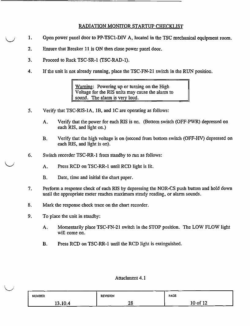
RADIATION MONITOR STARTUP CHECKLIST
1. Open power panel door to PP-TSC1-DIV A, located in the TSC mechanical equipment room.
2. Ensure that Breaker 11 is ON then close power panel door.
3. Proceed to Rack TSC-SR-1 (TSC-RAD-1).
4. If the unit is not already running, place the TSC-FN-21 switch in the RUN position.
Wa|ing: Powering up or turning on the HighVoltage for the RIS units may cause the alarm tosound. The alarm is very loud.
5. Verify that TSC-RIS-IA, 1B, and IC are operating as follows:
A. Verify that the power for each RIS is on. (Bottom switch (OFF-PWR) depressed oneach RIS, and light on.)
B. Verify that the high voltage is on (second from bottom switch (OFF-HV) depressed oneach RIS, and light is on).
6. Switch recorder TSC-RR-1 from standby to run as follows:
A. Press RCD on TSC-RR-1 until RCD light is lit.
B. Date, time and initial the chart paper.
7. Perform a response check of each RIS by depressing the NOR-CS push button and hold downuntil the appropriate meter reaches maximum steady reading, or alarm sounds.
8. Mark the response check trace on the chart recorder.
9. To place the unit in standby:
A. Momentarily place TSC-FN-21 switch in the STOP position. The LOW FLOW lightwill come on.
B. Press RCD on TSC-RR-1 until the RCD light is extinguished.
Attachment 4.1
NUMBER REVISION PAGE
13.10.4 28 l0 ofl12
Duties: Health Physics Network (HPN) Communicator
Assigned Location: Technical Support Center (TSC)
Report To: Radiation Protection Manager (RPM)
Activation Level: Alert or Higher Classification
Responsibilities:
1. Upon assignment, obtain a briefing from the RPM on the current status of the emergency andthe known or anticipated radiological conditions and/or releases.
2. Activate the TSC extension of the HPN phone, introduce yourself to the NRC communicatorand provide information you have on the current status of onsite and offsite radiologicalconditions.
3. After assuming this responsibility, observe the requirements of 1OCFR50.72(c)(3) bymaintaining continuous communications when requested by the NRC. If you leave the phonefor any reason, find someone to maintain the phone in your absence.
4. Maintain a log of your communications with the NRC on the Emergency Response Log,(Form -23895).
5. Notify the RPM when you require assistance with resolving NRC information requests orwhen you are asked to make commitments you do not feel you are authorized to make.
6. As conditions allow, brief the RPM on the status of HPN communications with the NRC.
7. Ensure transmissions you relay are distinct and understood. Avoid the use of acronymsunless you are sure they are understood and ensure the correct letters of acronyms areunderstood by using phonetic spelling to clarify, i.e., "B" as in Bravo or "D" as in Delta.
8. Ensure data you transmit to the NRC represents factual information only. Avoid speculativeinformation or editorializing on data and do not engage in problem solving discussions.
Attachment 4.2Page 1 of 2
NUMBER REVISION PAGE
13.10.4 28 11 of 12
9. When relieved of HPN Communicator duties by an EOF Communicator:
a. Brief your relief on the status of the plant radiological conditions and on pertinentinformation you have given to the NRC communicator.
b. Obtain an acknowledgment from the EOF HPN Communicator that they are ready toassume HPN communications.
c. Obtain permission from NRC to discontinue communications from the TSC.
d. Notify the RPM you have been relieved.
e. Submit all logs of your communications with the NRC to the RPM.
10. Upon shift change, brief your relief on responsibilities, duties and the current status of HPNcommunications with the NRC.
11. Upon shift change or termination of the emergency:
a. Prepare an individual After Action Report. Refer to PPM 13.13.4.
b. Deliver After Action Report and logs to the RPM.
Attachment 4.2Page 2 of 2
NUMBER REVISION PAGE
13.10.4 28 12 of 12
1IJI 3ll IGII IIIGI 7I I1n *13.10.7*l
X NEGYUSECUkETREVISION( NORTHWESTPeople*Vision * Solutions
COLUMBIA GENERATING STATIONPLANT PROCEDURES MANUAL
NUMBER |APPROVED BY |DATE
*13.10.7 |SLS - Revision 21 04/22/04
VOLUME NAME
EMERGENCY PLAN IMPLEMENTING PROCEDURESSECTION
PLANT EMERGENCY FACILITIESTITLE
PLANT ADMINISTRATIVE MANAGER DUTIES
TABLE OF CONTENTS
Page
PURPOSE ...................................
REFERENCES ................................
PROCEDURE ................................
3.1 Plant Administrative Manager Responsibilities ............3.2 TSC Relocation ................................
4.0 ATTACHMENTS ...................................
4.1 Technical Support Center Status Board/Information Coordinator4.2 Technical Support Center Administrative Support Staff ......
. 3
. 8
. 9
1011
NUMBER REVISION PAGE
13.10.7 21 1 of 14
1.0 PURPOSE
This procedure describes the emergency responsibilities and duties of the Plant AdministrativeManager in the Technical Support Center. These duties include administrative and logisticalsupport in the procurement of critical supplies, equipment, and personnel scheduling for theplant emergency and recovery response. The Plant Administrative Manager will coordinatewith the Emergency Operations Facility Site Support Manager for resources needed to supportonsite emergency operations.
2.0 REFERENCES
2.1 FSAR, Chapter 13.3, Emergency Plan, Section 2.0
2.2 PPM 13.13.4, After Action Reporting
2.3 PPM 13.14.1, Nearby Nuclear Facility Emergencies/Requests for Assistance
2.4 PPM 13.5.1, Evacuation
2.5 PPM 13.5.5, Personnel Accountability, Search and Rescue
2.6 PPM 13.10.3, Technical Manager and Staff Duties
2.7 PPM 13.11.3, Site Support Manager and Staff Duties
2.8 PPM 13.11.18, Information Coordinator Duties
2.9 Emergency Classification or Other Emergency Message, 26045
2.10 Columbia Generating Station Public Address Emergency Message Format - ProtectedArea Evacuation, 26050
2.11 Columbia Generating Station Public Address Emergency Message Format -SiteEvacuation, 26051
2.12 Emergency Response Log, 23895
2.13 Classification Notification Form, 24075
2.14 Technical Support Center (TSC) Briefing Guidelines, 25860
2.15 TSC Staffing Chart, 26062
2.16 Columbia Generating Station OSC Staffing Chart, 26063
NUMBER REVISION PAGE
13.10.7 21 2 of 14
3.0 PROCEDURE
3.1 Plant Administrative Manager Responsibilities
3.1.1 Upon notification of an Alert, Site Area Emergency, or General Emergency, orif so directed, proceed to the Technical Support Center (TSC).
3.1.2 Log into TES and obtain dosimetry.
3.1.3 Present your keycard to the TSC cardreader located by the outer hallway accessdoor to establish electronic Personnel Accountability.
3.1.4 Enter your name on the TSC Accountability Log to establish manual PersonnelAccountability.
3.1.5 Enter your name on the TSC staffing board in the space next to youremergency position.
3.1.6 If not already out, obtain the Plant Administrative Manager emergencyresponse basket from the TSC Emergency Equipment Cabinet and ensure theAdmin Support positions are appropriately staffed.
3.1.7 If you leave the TSC temporarily, inform the TSC Manager of your destinationand approximate time of return. Note your destination on the TSC PersonnelAccountability Log.
3.1.8 Obtain a briefing from the TSC Manager, the Technical Manager or theOperations Manager on the current status of the plant and the actions beingtaken to mitigate the emergency.
3.1.9 Assure early establishment of Center accountability by ensuring TSC personnelpresent key cards to the card reader, and manual accountability log iscompleted and personnel have signed in on the staffing chart. Using form26062, designate extra responders as second shift personnel.
3.1.10 Determine if ERO personnel present for all TSC and OSC positions:
* Compare the individuals to the positions listed on forms 26062, TSCStaffing Chart, and 26063, OSC Staffing Chart. If all positions arefilled, inform the TSC Manager, EOF Manager, and the OSC Managerthat personnel present for all positions.
* Ensure TSC staff have signed in on the TSC sign in board.
NUMBER REVISION PAGE
13.10.7 21 3 of 14
* For unfilled positions, notify the TSC Manager and OSC Manager ofpositions which have not been contacted. Obtain a copy of theEmergency Phone Directory and begin contacting qualified respondersfor the open positions.
3.1.11 Manage the activities of the administrative support staff in the TSC to includethe duties of TSC Personnel Accountability, Facsimile and Records Assistance,and TSC Phone Communications.
NOTE: Public address announcements that direct protective actions, such asSite evacuation, are an Emergency Director responsibility.
3.1.12 When directed by the Emergency Director, make emergency PAannouncements in the plant and direct the Secondary Alarm Station Officer tomake emergency announcements over maintenance and security radio channelsper the steps on form 26045, Emergency Classification or Other EmergencyMessage.
* If PA announcements require an action to be taken, sound the AlertingTone. If no action is required, omit the use of the Alerting Tone.
* PA announcements following emergency classifications should be madeas soon as possible and should occur within about five minutes of theannouncement in the TSC. Announcements should include theclassification, the time of the classification, a brief description of theclassification, applicable protective actions, and follow the format onform 26045.
* Update announcements should occur as directed by the TSC Managerand should include as a minimum hazardous areas to avoid, theclassification, and evacuations until complete.
3.1.13 When notified of a Site Evacuation, confer with the Radiation ProtectionManager to determine if special evacuation routes are necessary and makeappropriate PA announcements.
* PA announcements for Site evacuations should be integrated with theannouncement for the Site Area Emergency. At Site Area Emergencyan evacuation of the Protected Area must take place to ensureaccountability within 30 minutes of the PA announcement. The PAannouncement should use form 26051, Columbia Generating StationPublic Address Emergency Message Format - Evacuation.
3.1.14 When notified of a site evacuation, confer with the RPM for appropriateactions to take. A Site evacuation is an automatic action at Site AreaEmergency.
NUMBER REVISION PAGE
13.10.7 21 4 of 14
* PA announcements for Site evacuation should occur as soon as possiblefollowing identification of the need to evacuate. PA announcementsshould use form 26051, Columbia Generating Station Public AddressEmergency Message Format - Site Evacuation.
3.1.15 Direct administrative staff to compile a TSC staffing report on form 26062 andan OSC staffing report on form 26063, and fax them to the Site SupportManager at the EOF.
3.1.16 Coordinate with the Site Support Manager in the Emergency OperationsFacility (EOF) to:
* Call out the ERO for all emergency centers in the event of asimultaneous failure of the Dialogic autodialer system and the radiopaging system, making it impossible to contact the ERO normally.Refer to the Part B Notification Checklist to summon the on call EROteam for each center.
Establish relief schedules to provide continuous personnel support forthe plant, as needed.
* Provide transportation, food, and other logistical support for plantemergency personnel.
Arrange for required training of Energy Northwest or offsite agencypersonnel responding to support emergency or recovery operations.
* Obtain necessary offsite support services and equipment.
* Obtain assistance necessary for making offsite deliveries to the site.
3.1.17 If it becomes necessary for the TSC to initiate relief shift staffing, use theEmergency Manpower Schedule, (26094) to establish a relief shift schedule fortwo 12 hour shifts, with start times of 0600 and 1800 or other hours, asdirected by the Emergency Director, at 24 hours duration. Establish three 12hour shift staffing when additional staff becomes available.
Team B should be contacted to relieve Team A, Team C contacted to relieveTeam B, Team D contacted to relieve Team C, and Team A contacted torelieve Team D.
Prior to contacting ERO members, determine from the RadiologicalProtection Manager and Security if any hazardous or security conditionsrequire special response instructions to responding personnel. Considerationmay need to be given for responding personnel to assemble at a remotelocation so that pool transportation or monitoring escort may be arranged.
NUMBER PAGE
13.10.7 21 5 of 14
* Maintain a projected 36 hour schedule until the emergency isterminated.
* Identify safe access routes to the plant.
* When it is determined that a shift change is required, activate theautodialer and initiate an on the fly message to the ERO using theManpower Schedule Message (26095).
CAUTION: If you initiate a scenario and a scenario is already running,select the STOP option from the menu to cancel the running scenariobefore you activate the new scenario.
1) Dial 9-375-1809 when prompted by the Remote ActivationModule. Enter the password and pound sign.
2) Enter 1000 for the scenario number, and press the pound key.This will activate the pagers and phones.
3) Read the prepared message on form 26095 when prompted.Press the pound key when done.
4) Press "3" to start the scenario. Press the pound sign to end thecall.
* Approximately two hours prior to shift change, initiate an informationalannouncement:
1) Contact the autodialer at 9-375-1809. When prompted by theRemote Activation Module, enter the password and the poundsign.
2) Enter 1010 for the scenario number, and press the pound key.This will not activate the pagers or phones.
3) Record your announcement.
4) Press "3" to start the scenario. Press the pound sign to end thecall.
* Review the final (one hour after start of notification) autodialer reportfor unfilled positions. If positions are unfilled, refer to the EmergencyPhone Directory for qualified responders and contact them via thetelephone.
NUMBER REVISION PAGE
13.10.7 21 6 of 14
3.1.18 As appropriate, ensure requests for procedure TCNs are reviewed andapproved in accordance with plant procedure requirements, or approved by aLicensed Senior Reactor Operator in accordance with 1OCFR50.54(x)requirements.
3.1.19 Arrange Plant Operations Committee (POC) meetings asnecessary and ensure meeting records are included with the Final After ActionReport.
3.1.20 When necessary, provide the necessary administrative support for procedurewriting during reentry/recovery operations.
3.1.21 If prolonged emergency operations are anticipated or additional staff resourcesare needed, refer to the ERO Phone List located in the Emergency PhoneDirectory and determine what Emergency Response Organization (ERO)members are qualified to provide shift relief along with a home phone numberwhere they can be reached.
3.1.22 When necessary, obtain the necessary equipment and personnel to provideadministrative support for writing special procedures during emergency orrecovery operations and coordinate procedures requiring prior NRC approvalthrough the TSC Plant/NRC Liaison position.
3.1.23 Keep the TSC Manager briefed on the status of administrative supportactivities. Refer to the Plant Administrative Manager's portion of theTechnical Support Center (TSC) Briefing Guidelines (25860) located in theTSC.
3.1.24 Refer incoming media calls to the Joint Information Center (JIC).
3.1.25 Upon shift change, fully brief your relief on duties, responsibilities and currentstatus of work being performed.
3.1.26 Upon shift change or termination of the emergency:
a. Prepare an individual After Action Report. Refer to PPM 13.13.4.
b. Collect the individual After Action Reports prepared by staff personnel.
c. Deliver all After Action Reports to the TSC Manager.
d. At termination of the event, provide the TSC Manager withadministrative support in compiling TSC After Action Reports anddeveloping a summary report of TSC performance.
NUMBER REVISION PAGE
13.10.7 21 7 of 14
3.2 TSC Relocation
3.2.1 If the TSC functions can no longer be implemented from the TSC, the TSCstaff will relocate to the Control Room or other location as designated by theTSC Manager. Announce to the TSC staff that the following supplies shouldbe taken with them to the alternate location:
Position specific proceduresAccountability LogsOSC and TSC staffing chartsFax log and received faxesFlip chart tablets and markersHard hat, safety glasses, and hearing protection
3.2.2 Prior to departure, contact the TSC RPM and determine the safe access route tothe alternate location. Direct the TSC staff to use the safe access route.
3.2.3 Coordinate responsibility for PA announcements with the Control RoomSupervisor and Incident Advisor/STA.
3.2.4 If relocating to the Control Room, prior to departure, determine if the TSCManager has informed the Shift Manager of the arrival of TSC personnel. Ifnot, contact the Shift Manager and inform him of the pending arrival.
3.2.5 If relocating to the Control Room, remind TSC staff to:
* Proceed to the Control Room promptly.* Upon arrival at the Control Room, check in with the Shift Manager and
assemble at the drawing table towards the rear of the Control Room.* Do not disrupt emergency response activities in progress by Control
Room staff.
I
NUMBER REVISION PAGE
13.10.7 21 8 of 14
4.0 ATTACHMENTS
4.1 Technical Support Center Status Board/Information Coordinator
4.2 Technical Support Center Administrative Support Staff
NUMBER REVISION PAGE
13.10.7 21 9of14
Duties of: Technical Support Center Status Board/Information Coordinator
Assignment Location: Technical Support Center
Report to: Plant Administrative Manager
Activation Level: Alert, or Higher Classification
Responsibilities
1. Log into TES and obtain dosimetry.
2. Present your keycard to the TSC cardreader located by the outer hallway access door toestablish electronic personnel accountability.
3. Write your name on the TSC staffing board in the space next to your emergency position.
4. Enter your name on the TSC Accountability Log located in the divider in the table just insidethe TSC.
5. Transmit and/or request data, as appropriate, per PPM 13.11.18 or at the direction of theTSC Manager.
6. Maintain assigned status board(s) that include, but are not limited to:
a. Significant eventsb. Plant statusc. Emergency Classification
7. Retain a copy of plant status information forms you generate and attach them to your AfterAction Report.
8. Assist with other administrative duties as directed by TSC Manager or Plant AdministrativeManager.
9. Refer incoming media calls to the Joint Information Center (JIC).
10. Upon shift change, fully brief your relief on responsibilities, duties, and the current status ofwork being performed.
11. Upon shift change or termination of the emergency:
a. Prepare an individual After Action Report. Refer to PPM 13.13.4.b. Deliver After Action Reports, and all logs to the Plant Administrative
Manager.
Attachment 4.1
NUMBER REVISION PAGE
13.10.7 21 10 of 14
Duties of: Technical Support Center Administrative Support Staff
Assignment Location: Technical Support Center
Report to: Plant Administrative Manager
Activation Level: Alert, or Higher Classification
Responsibilities
1. Log into TES and obtain dosimetry.
2. Present your keycard to the TSC cardreader located by the outer hallway access door toestablish electronic personnel accountability.
3. Write your name on the TSC staffing board in the space next to your emergency position.
4. Enter your name on the TSC Accountability Log located in the divider in the table just insidethe TSC.
a. After the TSC is staffed, check the log against the wall staffing board to ensure allTSC personnel have signed in at both locations.
5. Ensure the Emergency Response Supply Cabinet is open. If necessary, obtain the padlock keyfrom the red key case on the side of the cabinet.
6. Obtain your Emergency Response position ID and an Emergency Phone Directory from thecabinet.
7. Advise the Plant Administrative Manager of your arrival and, if required, assist withpreparing the TSC for activation.
8. Perform the following TSC Administrative Support Staff functions as necessary:
NOTE: Should delays be encountered in performing assigned duties because of heavy workactivity, request additional assistance from the Plant Administrative Manager, or ask otherTSC staff members to assist if they are able.
Attachment 4.2Page 1 of 4
NUMBER REVISION PAGE
13.10.7 21 11 of 14
a. TSC Personnel Accountability
1) Place the Personnel Accountability Log located on the Admin Support Staffdesk on the table at the entrance to the TSC and ensure personnel entering theTSC enter their name on the form.
2) When necessary, direct TSC personnel to obtain temporary dosimetry orkeycard into the TSC.
3) Ensure that TSC personnel leaving the TSC:
Obtain briefing from the RPM in the TSC on radiological conditionsthat affect areas or routes they will be in;
* Are properly logged out, and logged in when they return.
4) If KI is taken by personnel in the TSC, record the action on the AccountabilityLog.
b. TSC Phone Assistance
1) Assist the TSC staff with incoming telephone traffic by answering phones whenTSC members are not available. Take down basic information from callers orobtain a call back number.
2) If a phone message is received that contains information you deem important,announce it loudly so that impacted TSC staff are aware.
c. TSC Facsimile Assistance
1) Upon arrival, check the dedicated receive facsimile machine and ensure thetoggle switch located on the fax is set to 207 (the dedicated fax number).Ensure that the correct time and date are set on both receive and send faxmachines.
2) Make a copy of documents provided to you for faxing and return the original tothe person requesting you to fax.
3) Log all incoming and outgoing faxes into the Fax Log Book located on yourdesk.
a) Number all incoming and outgoing faxes beginning with No. 1 and writethe documents log number in the upper right corner of the document.
Attachment 4.2Page 2 of 4
NUMBER REVISION PAGE
13.10.7 21 12 of 14
4) For outgoing faxes, attach the confirmation slip to the document and file.
5) For incoming faxes, log and make a copy for files, and route as addressed. Ifnot addressed, deliver to the Plant Administrative Manager for routingdirections.
6) For incoming CNFs and news releases, copy the:
TSC Manager
Operations Manager
Technical Manager
Maintenance Manager
Radiation Protection Manager
Plant Administrative Manager
Plant/NRC Liaison
Chemistry/Effluent Manager
TSC Information Coordinator
All NRC personnel, if present
7) Route outgoing fax messages as addressed or distributed in accordance with theFax Outgoing Distribution Guide.
8) When a CNF is originated from the TSC by the TSC Manager, transmit it tothe following agencies or emergency centers, using group dial feature, asappropriate:
Benton County EOCFranklin County EOCState of Washington EOCDOE-RLSCCEOFOSCJIC
If the group dial feature fails to operate, send the fax to each locationseparately in the order listed above.
Attachment 4.2Page 3 of 4
NUMBER REVISION PAGE
13.10.7 21 13 of 14
d. TSC Records Assistance
1) Distribute copies of the Emergency Response Log (23895) for use by the TSCstaff to record their emergency activities.
2) Perform record searches, retrievals, or other administrative support tasks at therequest of the Plant Administrative Manager or TSC staff.
NOTE: All PPMs located in the TSC are Level One Controlled.
3) When required, inspect and provide verification for the most up to daterevision of records/drawings required for TSC emergency operations. If copiesare made from these procedures, initial and date the cover sheet in the upperright corner.
4) Perform other functions within the scope of administrative support duties asassigned by the Plant Administrative Manager.
5) Refer incoming calls to the Joint Information Center.
6) Upon shift change, brief your relief on your work responsibilities, duties, andthe current status of work being performed.
7) Upon shift change or termination of the emergency:
* Distribute copies of After Action Reports (Attachment 6.1 of PPM13.13.4) to the TSC staff.
* Prepare an individual After Action Report. Refer to PPM 13.13.4.
* Deliver your After Action Report, with pertinent logs attached, to thePlant Administrative Manager.
Attachment 4.2Page 4 of 4
NUMBER REVISION PAGE
13.10.7 21 14 of 14
IIII 1 l itll l h l iD ll illllll 1111*13 .11. 3*
X E NERGY |USECUkRENT REVSIUlN
NORTHWEST IPeople Vision Solutions
COLUMBIA GENERATING STATIONPLANT PROCEDURES MANUAL
PROCEDURE NUNIBER |APPROVED BY |DATE
*13.11.3 SLS - Revision 23 04/22/04
VOLUME NAME
EMERGENCY PLAN IMPLEMENTING PROCEDURES
SECTION
EMERGENCY OPERATIONS FACILITY
TITLE
SITE SUPPORT MANAGER AND STAFF DUTIES
TABLE OF CONTENTS
1.0 PURPOSE ............................................
2.0 REFERENCES .........................................
3.0 PROCEDURE .........................................
3.1 Site Support Manager Duties ...........................
4.0 ATTACHMENTS .......................................
4.1 Manpower Scheduler Duties ............................4.2 EOF Administrative Support Staff Duties ...................4.3 Telecommunications Manager Duties ......................4.4 General Emergency Airspace or Airport Closure Request.4.5 Site Support Manager Briefing Guidelines ...................
Page
.... 2
.... 2
.... 2
.... 6
.... 1
... 10
... 13... 14... 15
PROCEDURE NUMBER REVISION PAGE
13.11.3 23 1 of 15
1.0 PURPOSE
This procedure describes responsibilities and duties of the Site Support Manager. The SiteSupport Manager provides support to the plant and secures assistance and supplies during theemergency and recovery phases. The Site Support Manager supervises the EOF InformationCoordinator, the Telecommunications Manager, Manpower Scheduler, and the EOF AdminSupport Staff.
2.0 REFERENCES
2.1 FSAR, Chapter 13.3, Emergency Plan, Section 4.4.2.2
2.2 OER SIL324R6, BWR Emergency Support Program
2.3 PPM 13.4.1, Emergency Notifications
2.4 PPM 13.5.1, Evacuation
2.5 PPM 13.11.18, Information Coordinator Duties
2.6 PPM 13.13.4, After Action Reporting
2.7 Emergency Response Log, Form 23895
2.8 Classification Notification Form, Form 24075
2.9 EOF Staffing and Organization Chart, Form 26061
2.10 Emergency Manpower Schedule, Form 26094
2.11 Manpower Schedule Message, Form 26095
3.0 PROCEDURE
3.1 Site Support Manager Duties
3.1.1 Report to the EOF when notified of an Alert, Site Area or General Emergency,or if directed.
3.1.2 Notify the EOF Manager of your availability.
3.1.3 Maintain an Emergency Response Log (23895) of the actions you take.
PROCEDURE NUMBER REVISION PAGE
13.11.3 23 2 of 15
3.1.4 Determine if ERO personnel have been notified for all EOF positions:
* Obtain the Dialogic printout available in the Logistics Area.
* Compare the list of individuals indicating they are responding to thepositions listed on the EOF Staffing Chart. If all positions areresponding, inform the EOF Manager that personnel have been notifiedfor all EOF positions.
* For unfilled positions, obtain a copy of the Emergency Phone Directoryand begin contacting qualified responders for the open positions. Notifythe EOF Manager of any positions which cannot be contacted.
3.1.5 In the event of a simultaneous failure of the Dialogic autodialer and the radiopaging system, direct the Manpower Scheduler to coordinate with the TSC PlantAdmin Manager to call out the ERO using the Part B Notification Checklist tosummon the on call ERO team for each center.
3.1.6 Ensure that the Significant Events Status Board and other appropriate displayssuch as the classification, plant status, and Emergency Classification/ProtectiveAction Status display are maintained by the Information Coordinator.
3.1.7 As personnel arrive for center activation, complete an EOF Staffing andOrganization Chart (26061) for all first shift responders. Complete a secondstaffing chart for second shift Essential personnel. Distribute copies to EOFManagers.
3.1.8 Compile a copy of staffing and organization charts received from the JIC, TSCand OSC and forward them to the Manpower Scheduler.
NOTE: All requests for outside assistance must first be approved by theEmergency Director.
3.1.9 Obtain outside assistance, equipment or personnel as directed by the EmergencyDirector. Coordinate deliveries with the Security Manager and the RadiologicalEmergency Manager.
a. When contacted by the TSC Technical Manager to determine if AsheSubstation operators are present at the Offsite Assembly Area, contact theJIC HP Spokesperson. If present, request that Ashe operators bereturned to the site. Coordinate arrival at the site with HP coverage ifnecessary and Security for site access.
b. When requested by the TSC Technical Manager, contact Dittmer ControlCenter to request BPA personnel for emergency response at ColumbiaGenerating Station. Request that a team be assembled and dispatched tothe Offsite Assembly Area to arrange for HP coverage if needed, receivea briefing of the event, and how to respond to the site.
PROCEDURE NUMBER REVISION PAGE
13.11.3 - 23 3 of 15
3.1.10 Assign and supervise administrative support staff as they arrive.
3.1.11 If Site evacuees need transportation, coordinate with the Plant Admin Managerin the TSC to make a public address announcement to direct the evacuees to theappropriate assembly area.
a. Arrange transportation for evacuation of personnel, if needed. Conferwith the Security Manager and Radiological Emergency Manager toidentify an on site assembly area for evacuees to meet theirtransportation.
b. Contact Construction & Maintenance Services to obtain a vehicle totransport evacuees to the Offsite Assembly Area.
3.1.12 If the state or county is not represented at the EOF, request the State and CountyLiaison to obtain information on county response actions from the EnergyNorthwest representative at the Washington State, Benton, and Franklin CountyEmergency Operations Centers (EOC).
NOTE: The SCC provides Part C notifications of plant emergency classificationlevels until relieved of this responsibility.
3.1.13 Contact the Security Communications Center (SCC) Duty Officer and assumeresponsibility for making the Part C Notifications in accordance withPPM 13.4.1.
a. Make the Part C notifications as required for the appropriate eventclassifications by providing information on items 2-6 on the CNF, asrequested (phone numbers are located in the Emergency Phone Directoryunder Offsite Notification Checklist).
3.1.14 Keep the EOF Manager informed of offsite agencies' decisions, requests, andoffers of assistance that are brought to your attention.
3.1.15 When the Site is evacuated, contact the FFTF Control Room and inform themof this action. This is a courtesy call and no action is required of FFTF at thistime. Refer to the Emergency Phone Directory, Offsite Agency tab, for thephone number.
3.1.16 At General Emergency, recommend an airspace or airport closure request withthe Federal Aviation Administration (FAA), Attachment 4.4.
a. Copy the completed Attachment 4.4 airspace closure request form andprovide it per the distribution list on the Attachment.
b. If airspace or airport closure occurs, and you become aware that aircraftproviding support for emergency operations may need airspace or airport
PROCEDURE NUMBER REVISION PAGE
13.11.3 23 4 of 15
access, request exceptions with the FAA.
3.1.17 Support EOF briefings per Attachment 4.5.
3.1.18 Coordinate the obtaining of resources needed to support emergency operationsthat include, but are not limited to:
NOTE: The on call procurement person should be contacted to assist withprocurement and purchasing services. Refer to the Emergency Phone Directoryfor the roster.
a. Administrative services and equipment
b. Accommodations and transportation for responding offsite personnel,including GE personnel responding to the site under the BWR EmergencySupport Program.
c. Finance and purchasing services
d. Commissary services
e. Emergency Response Organization shift relief (for prolongedemergencies)
f. Labor Relations or Human Resources services
g. Legal or insurance services
h. Facility Services
3.1.19 Coordinate with the Plant Administrative Manager on providing personnel,equipment, training, or other administrative resource support for the plant staff.
3.1.20 Coordinate delivery of food and other services with the Security Manager,Radiological Emergency Manager, and the JIC Support Manager.
3.1.21 Discuss relief shift scheduling with the Emergency Director, and arrange forEmergency Response Organization (ERO) relief staffing, if necessary, accordingto instructions outlined in Attachment 4.1.
3.1.22 When preparing to enter the recovery phase, compile the recovery action listsdeveloped by the TSC and OSC, which identify short and long term recoveryitems. Forward these action lists to the EOF Manager for input into the masterrecovery plan.
3.1.23 Refer any calls from the media to the Joint Information Center.
PROCEDURE NUMBER REVISION PAGE
13.11.3 23 5 of 15
3.1.24 Brief your relief on items of note that happened during your shift and on statusof ongoing work.
3.1.25 Upon shift change or termination of the emergency:
a. Prepare an individual after action report. Refer to PPM 13.13.4.
b. Collect the individual after action reports prepared by staff personnel.
c. Deliver all individual after action reports and Emergency Response Logsto the Assistant EOF Manager.
3.1.26 Participate as a member of the After Action Report Committee chaired by theAssistant EOF Manager when required.
4.0 ATTACHMENTS
4.1 Manpower Scheduler Duties
4.2 EOF Administrative Support Staff Duties
4.3 Telecommunications Manager Duties
4.4 General Emergency Airspace or Airport Closure Request
4.5 Site Support Manager Briefing Guidelines
PROCEDURE NUMBER REVISION PAGE
13.11.3 23 6 of 15
Duties of: Manpower Scheduler
Assigned Location: Emergencv Operations Facility (EOF)
Report To: Site Support Manager
Activation Level: Alert, or Higher Classification
Responsibilities
1. On arrival at the EOF, sign in on the staffing board and report your availability to the SiteSupport Manager.
2. Maintain an Emergency Response Log (23895) of the actions you take.
3. Assist the Site Support Manager with preparing an EOF Staffing and Organization Chart forfor all first shift responders. Complete a second staffing chart for second shift Essentialpersonnel. Obtain completed charts from other emergency centers, and compiling charts fordistribution to EOF Managers. Distribute completed EOF staffing charts to the TSC, OSC, andJIC.
4. Assist the Site Support Manager with contacting and obtaining resources to support theEmergency Response Organization (ERO).
5. Fill open positions in the emergency centers by contacting qualified individuals.
a. Refer to the Emergency Phone Directory, Part B Notifications section. This should bebehind a tab titled, "ERO".
b. Locate the applicable emergency center position for qualified individuals' phone andpager numbers.
c. Confirm the individual contacted meets fitness for duty requirements.
6. When directed by the Site Support Manager, initiate actions for staffing relief shifts.
NOTE: Plant Operations and Security are on rotating schedules. Additional ERO positionswill be coordinated by Operations and Security management.
a. Contact the Plant Administrative Manager in the TSC and determine Plant Operationsand Control Room shift change requirements for the current on-shift staff. This shouldinclude identification of the crew relieving the on-shift crew and the time of the shiftchange.
Attachment 4.1Page 1 of 3
PROCEDURE NUMBER REVISION PAGE
13.11.3 23 7 of 15
b. Contact the Security Manager in the EOF and determine Security shift changerequirements for the current on-shift staff. This should include identification of the crewrelieving the on-shift crew and the time of the shift change.
7. In the event of a simultaneous failure of the Dialogic autodialer and radio paging system, andwhen directed by the Site Support Manager, coordinate with the TSC Plant Admin Manager tocall out the ERO using the Part B Notification Checklist to summon the on call ERO team foreach center.
8. Contact the REM to:
* Identify safe access routes to the plant.
* When it is determined that a shift change is required, activate the autodialer at 9-375-1809 and initiate an on the fly message to the ERO using the Manpower ScheduleMessage (26171), and the following instructions:
CAUTION: If you initiate a scenario and a scenario is already running, select the STOP optionfrom the menu to cancel the running scenario before you activate the new scenario.
Team B should be contacted to relieve Team A, Team C contacted to relieve Team B, Team Dcontacted to relieve Team C, and Team A contacted to relieve Team D.
a) Call the autodialer at 375-1809. When prompted by the Remote Activation Module, enterINFO (4636) as the password and the pound sign.
b) Enter 1000 for the scenario number, and press the pound key. This will activate thepagers and phones.
c) Read the prepared message on form 26171 when prompted. Press the pound key whendone.
d) The dialer will prompt you for verification.
9. Approximately two hours prior to shift change, initiate an informational announcement(scenario 1010).
a) Prior to contacting ERO members, determine from the Radiological Emergency Manager(REM) and Security Manager if any hazardous or security conditions require specialresponse instructions to responding personnel. Consideration may need to be given forresponding personnel to assemble at a remote location so that pool transportation ormonitoring escort may be arranged.
Attachment 4.1
PROCEDURE NUMBER REVISION PAGE
13.11.3 23 8 of 15
Page 2 of 3
b) Contact the autodialer at 9-375-1809. When prompted by the Remote Activation Module,enter the password (INFO) and the pound sign.
c) Enter 1010 for the scenario number, and press the pound key. This will not activate thepagers or phones.
d) Record your announcement.
e) The dialer will prompt you for verification.
10. Review the final (one hour after the start of notification) autodialer report for unfilledpositions. If positions are unfilled, refer to the Emergency Phone Directory for qualifiedresponders and contact them via the telephone.
11. Notify the Site Support Manager or the JIC Support Manger, as appropriate, of any EROpositions you are unable to fill.
12. Furnish a copy of the compiled list of relief/supplemental staff to center managers.
13. When contacted with requests for information about employees involved with the emergency:
* Take a call back number and message, and forward the message and number to theindividual.
- Refer to the Emergency Phone Directory for individual center assignment andphone number.
* Refer emergency messages to personnel as needed.
* Refer to the autodialer report to determine ERO personnel present.
14. Refer any calls from the media to the Joint Information Center (372-5100).
15. Brief your relief on items of note that happened during your shift and on status of ongoingwork.
16. On shift change or termination of the emergency:
a. Prepare an individual After Action Report. Refer to PPM 13.13.4.
b. Deliver all After Action Reports and logs to the Site Support Manager.
Attachment 4.1Page 3 of 3
PROCEDURE NUMBER REVISION PAGE
13.11.3 23 9 of 15
Duties of: EOF Administrative Support Staff
Assigned Location: Emergency Operations Facility EOF
Report To: Site Support Manager
Activation Level: Alert, or Higher Classification
Responsibilities
1. On arrival at the EOF, sign in on the staffing board and advise the Site Support Manager ofyour availability.
2. As necessary, assist with preparing the EOF for operations and answer phones for EOF staffthat have not arrived. Take down basic information from callers or get a number for the EOFstaff member to call back.
3. Check the EOF facsimile machines to ensure power is on and the date and time is correctly set.Set facsimile time with the EOF's 24-hour clock time.
4. Install batteries in the Crash phone headsets and distribute to positions around the horseshoearea.
5. Check operability of cordless microphones and distribute the primary microphone to the EOFManager, and the backup to the Information Coordinator.
6. Distribute the position supply baskets from the cabinet to their locations.
7. Make a copy of PPM 13.11.3, Site Support Manager and Staff Duties, and distribute theattachments to the Manpower Scheduler and Admin Support Staff.
8. Make a copy of PPM 13.11.18 for the EOF Information Coordinator.
9. Perform general support tasks for EOF staff which includes:
a. Take or deliver messages, or assist with log keeping.
NOTE: Emergency center staffing and organization charts that identify the EROpositions and the personnel staffing those positions can be obtained from the Site SupportManager.
b. Provide facsimile transmittal and EOF distribution services for emergency-relateddocuments.
c. During drills, stamp all outgoing documents with "Drill Use" prior to distribution orfaxing.
Attachment 4.2Page 1 of 3
PROCEDURE NUMBER REVISION PAGE
13.11.3 23 10 of 15
1) When you receive a Classification Notification Form (CNF) (24075) that isoriginated by the EOF, transmit the CNF using the group dial according to thedistribution list located at the facsimile machine or obtain direction from the SiteSupport Manager.
2) Notify the Site Support Manager immediately if there are any malfunctions orother delays in transmitting the CNF.
3) For all other document transmittals or distributions, ask for direction from theSite Support Manager if needed.
4) Retain all originals of facsimile documents, with facsimile activity reports.
5) Maintain a log of incoming and outgoing facsimile documents by sequentialnumber and description.
c. Locate and replenish EOF office supplies
NOTE: If you must leave the EOF area of the Kootenai Building to obtain supplies,check with the Radiological Emergency Manager (REM) first to obtain information onany hazardous areas to avoid.
d. Provide duplicating services.
e. Verify or duplicate procedures for EOF staff use.
NOTE: Volume 13 Plant Procedure Manuals (PPMs) located in the EOF procedurebookcase on the south wall are Level 1 Control copies. EOF Library PPM manuals areLevel 2 Control. Before use, they must be verified using Passport DocumentManagement System or verified from a Level 1 source such as the TSC or ControlRoom.
f. Assist with distributing food or beverage services to EOF personnel.
g. Assist with calls to ERO relief/supplemental personnel if requested.
NOTE: An ERO Phone Directory which lists home phone numbers for ERO personneland an Energy Northwest Directory containing work phone numbers are included in theEmergency Phone Directories.
10. Refer any calls from the Media to the Joint Information Center (JIC).
Attachment 4.2Page 2 of 3
PROCEDURE NUMBER REVISION PAGE
13.11.3 23 11 of 15
11. Provide administrative assistance to EOF PIO as requested.
12. On shift change or termination of the event:
a. Brief your relief on items of note that happened during your shift and on status ofongoing work.
b. Prepare an After Action Report. Refer to PPM 13.13.4.
c. Deliver your After Action Report and any logs to the Site Support Manager.
13. At event termination, assist with collating EOF staff after action documentation and returningthe EOF to ready configuration.
Attachment 4.2Page 3 of 3
PROCEDURE NUMBER REVISION PAGE
13.11.3 23 12 of 15
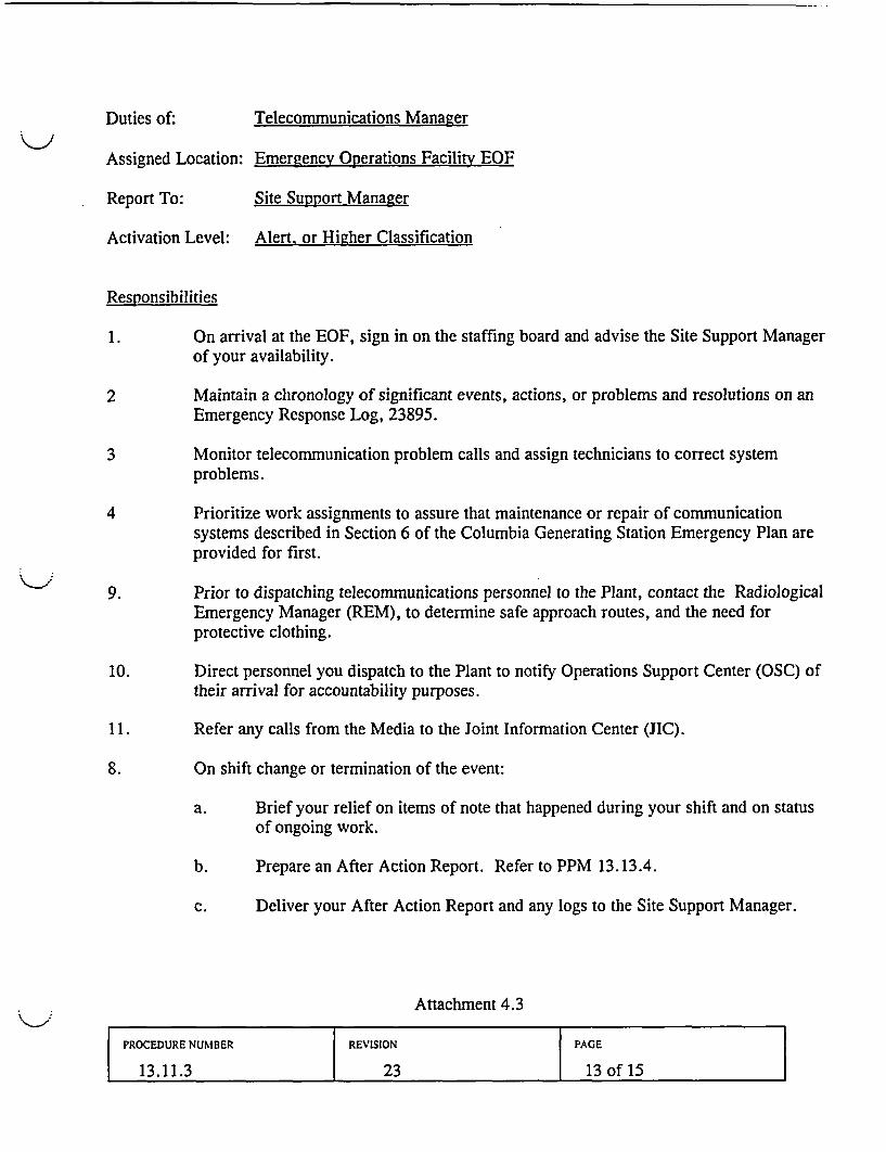
Duties of: Telecommunications Manager
Assigned Location: Emergencv Operations Facility EOF
Report To: Site Support Manager
Activation Level: Alert, or Higher Classification
Responsibilities
1. On arrival at the EOF, sign in on the staffing board and advise the Site Support Managerof your availability.
2 Maintain a chronology of significant events, actions, or problems and resolutions on anEmergency Response Log, 23895.
3 Monitor telecommunication problem calls and assign technicians to correct systemproblems.
4 Prioritize work assignments to assure that maintenance or repair of communicationsystems described in Section 6 of the Columbia Generating Station Emergency Plan areprovided for first.
9. Prior to dispatching telecommunications personnel to the Plant, contact the RadiologicalEmergency Manager (REM), to determine safe approach routes, and the need forprotective clothing.
10. Direct personnel you dispatch to the Plant to notify Operations Support Center (OSC) oftheir arrival for accountability purposes.
11. Refer any calls from the Media to the Joint Information Center (JIC).
8. On shift change or termination of the event:
a. Brief your relief on items of note that happened during your shift and on statusof ongoing work.
b. Prepare an After Action Report. Refer to PPM 13.13.4.
c. Deliver your After Action Report and any logs to the Site Support Manager.
Attachment 4.3
PROCEDURE NUMBER REVISION PAGE
13.11.3 23 13 of 15
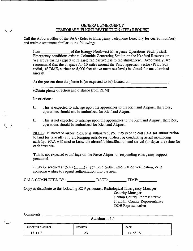
GENERAL EMERGENCYTEMPORARY FLIGHT RESTRICTION (TFR) REOUEST
Call the Auburn office of the FAA (Refer to Emergency Telephone Directory for current number)and make a statement similar to the following:
I am of the Energy Northwest Emergency Operations Facility staff.Emergency conditions exist at Columbia Generating Station on the Hanford Reservation.We are releasing (expect to release) radioactive gas to the atmosphere. Accordingly, werecommend that the airspace for 10 miles around the Pasco approach vector (Pasco 305radial, 18 DME, surface to 5,000 feet above mean sea level) be closed for unauthorizedaircraft.
At the present time the plume is (or expected to be) located at:
(Obtain plume direction and distance from REM)
Restrictions:
O This is expected to infringe upon the approaches to the Richland Airport, therefore,operations should not be authorized for Richland Airport.
O This is not expected to infringe upon the approaches to the Richland Airport, therefore,operations should be authorized for Richland Airport.
NOTE: If Richland airport closure is authorized, you may need to call FAA for authorizationto land (or take off) aircraft bringing outside responders, or conducting aerial monitoringactivity. FAA will need to know the aircraft's identification and arrival (or departure) time foreach instance.
This is not expected to infringe on the Pasco Airport or responding emergency supportpersonnel.
I may be reached at (509) L ) if you need further information verification, or ifsomeone wishes to request authorization into the area.
CALL COMPLETED BY: DATE: TIME:
Copy & distribute to the following EOF personnel: Radiological Emergency ManagerSecurity ManagerBenton County RepresentativeFranklin County RepresentativeDOE Representative
Comments:Attachment 4.4
PROCEDURE NUMBER REVISION PAGE
13.11.3 23 14 of 15
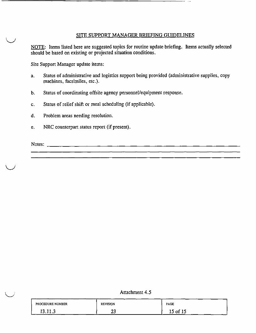
SITE SUPPORT MANAGER BRIEFING GUIDELINES
NOTE: Items listed here are suggested topics for routine update briefing. Items actually selectedshould be based on existing or projected situation conditions.
Site Support Manager update items:
a. Status of administrative and logistics support being provided (administrative supplies, copymachines, facsimiles, etc.).
b. Status of coordinating offsite agency personnel/equipment response.
c. Status of relief shift or meal scheduling (if applicable).
d. Problem areas needing resolution.
e. NRC counterpart status report (if present).
Notes:
Attachment 4.5
PROCEDURE NUMBER REVISION PAGE
13.11.3 23 15 of 15
*13.11.7*
S ENERGY USECUTREVISONNORTHWEST
People -Vision *-Solutions
COLUMBIA GENERATING STATION
PLANT PROCEDURES MANUAL
NUMBER APRVDBY DATE
*13.11.7 SLS - Revision 28 04/22/04
VOLUME NAME
EMERGENCY PLAN IMPLEMENTING PROCEDURES
SECTION
EMERGENCY OPERATIONS FACILITY
TITLE
RADIOLOGICAL EMERGENCY MANAGER DUTIES
TABLE OF CONTENTSPage
1.0 PURPOSE ....................................... 2
2.0 REFERENCES ..................................... 2
3.0 PROCEDURE ...................................... 4
4.0 ATTACHMENTS ..................................... 11
4.1 Checklist for Radiological Emergency Manager Duties ................... 124.2 Dose Projection Health Physicist Duties ............................. 184.3 Comparison of Field Data with Dose Projections ....................... 204.4 Health Physics Network (HPN) Communicator Duties .................... 214.5 Health Physics Center (HPC) Staff ................................ 224.6 Health Physics Center Staff Radiological Sample Tracking Instructions .... ..... 244.7 Typical Setup for HP Center Receiving Area .......................... 264.8 Radiological Emergency Manager Briefing Guidelines .................... 274.9 Total Population Within the 10 Mile EPZ ............................ 284.10 EOF HVAC Automatic and Manual Operation .294.11 Dose Assessment Center Leadership Transfer .31
NUMBER REVISION PAGE
13.11.7 28 1 of 31
1.0 PURPOSE
This procedure describes the emergency responsibilities and duties of the EmergencyOperations Facility (EOF) Radiological Emergency Manager (REM), including oversight of:Environmental Field Team activities; dose projection activities; Protective ActionRecommendation (PAR) coordination with the Emergency Director; coordinating any offsitemonitoring and decontamination activities; Health Physics Center (HPC) activities; andcoordination of offsite reentry and Ingestion Pathway activities with Washington StateDepartment of Health (WADOH) personnel. As necessary, portions of the REM duties maybe delegated to staff members.
Upon arrival of WADOH representatives and/or the U.S. Department of Energy, RichlandField Office (DOE/RL) representatives, certain REM duties will be administered according tothe jurisdictional authority of each agency, with the REM ensuring full cooperation andsupport to all agencies.
2.0 REFERENCES
2.1 FSAR, Chapter 13.3, Emergency Plan, Sections 2 and 6
2.2 PPM 1.9.14, Onsite Medical Emergencies
2.3 PPM 11.2.9.31, Operation of MG DMC-100 and DMC-2000 Electronic Dosimeters
2.4 PPM 13.2.1, Emergency Exposure Levels/Protective Actions Guides (PAGs)
2.5 PPM 13.2.2, Determining Protective Action Recommendations
2.6 PPM 13.5.1, Evacuation
2.7 PPM 13.7.5, Offsite Assembly Area Operations
2.8 PPM 13.8.1, Emergency Dose Projection System Operations
2.9 PER 201-2601, Honeywell Control Systems {P183283}
NUMBER REVISION PAGE
13.11.7 28 2 of 31

REFERENCES, (cont'd)
2.10 PPM 13.9.1, Environmental Field Monitoring Operations
2.11 PPM 13.9.5, Environmental Sample Collection
2.12 PPM 13.9.8, River Evacuation Monitoring
2.13 PPM 13.13.3, Intermediate Phase MUDAC Operations
2.14 PPM 13.13.4, After Action Reporting
2.15 Emergency Response Log, 23895
2.16 Ten Mile EPZ Field Team Summary Map, 25130
NUMBER REVISION PAGE
13.11.7 28 3 of 31
3.0 PROCEDURE
3.1 When notified of an Alert, Site Area Emergency or General Emergency, or if directed,report to the EOF and sign in on the EOF staffing board.
3.2 Obtain your procedure book from the bookcase and supply drawer from the EOFsupply cabinet.
3.3 Notify the EOF Manager (or the TSC Manager if EOF Manager not yet present) ofyour availability.
NOTE: MUDAC may be declared operational with less than minimum staffing,however, doing so does not satisfy minimum staffing requirements of the EmergencyPlan. Contact the Manpower scheduler to fill open positions.
3.4 Inform the EOF Manager when MUDAC is operational (capable of performing doseassessment and field monitoring functions).
NOTE: At an Alert or higher emergency, a Security Officer will be dispatched to theEOF HPC to lock down the Kootenai Building and assist with EOF access control.
3.5 At Alert or higher, direct activation of the ENOC Offsite Assembly Area.
3.6 Contact the RPM and request three HP Technicians to respond to the EOF. Dispatchthe Technicians to the Health Physics Center (HPC) to begin setting up the HPC perAttachment 4.7.
Upon completion of HPC set up, direct two of the Technicians to the ENOCOffsite Assembly Area to set up the Offsite Assembly Area per PPM 13.7.5.Direct the third HP to initiate EOF habitability monitoring.
3.7 Ensure appropriate radiological monitoring equipment (dose rate and air sampling) ispositioned in the lower level south end Kootenai Building near the EOF and periodicdose rate and airborne surveys are performed as necessary.
3.8 Establish and maintain contact with the RPM in the TSC for a briefing on the status ofthe emergency, and to provide assistance in radiological assessment, mitigationactivities, or dose assessments.
3.9 When dose assessment is fully functional, assume responsibility for offsite doseprojections from the RPM in the TSC, or the STA in the Control Room.
3.10 Provide an initial briefing on the emergency using Attachment 4.8 to the offsite agencyrepresentatives.
NUMBER REVISION PAGE
13.11.7 28 4 of 31
3.11 In the event of a Site evacuation, assist the RPM with coordinating Health Physics (HP)monitoring and decontamination services at the evacuation assembly area.
* Refer to PPM 13.5.1 for Site evacuation routes.
* Refer to PPM 13.7.5 for Alternate Assembly Area set up instructions.
3.12 If assistance is requested by Washington State Department of Health, provide forradiological monitoring of Columbia River evacuees per PPM 13.9.8.
3.13 If plant conditions indicate the possibility of an offsite release or a Site Area Emergencyis declared, direct the Site Support Manager to call in an additional REM to assist inREM responsibilities.
3.14 If the determination is made to evacuate the Site, determine if radiological hazards existor are suspected. Determine evacuation routes and hazardous routes to avoid. Refer toPPM 13.5.1.
3.15 Provide periodic updates on radiological conditions and evacuation actions.
3.16 In the event of an evacuation, contact the JIC HP Spokesperson and request that the HPTechnicians at the Offsite Assembly Area be informed that evacuees have been directedto report to the ENOC.
3.17 If conditions indicate the need for road closure, evacuation, or other protectivemeasures, coordinate the safe placement of Energy Northwest or local law enforcementagency roadblocks with the Security Manager.
NOTE: Security no longer maintains dosimetry in road block kits for responders, andwill direct personnel needing dosimetry to the EOF, except for fire and ambulancepersonnel who will obtain dosimetry at the vehicle trap.
3.18 When notified that personnel must pass through road blocks into radiological hazardareas, determine and implement necessary radiological monitoring and protectiveclothing requirements.
NOTE: The Energy Northwest administrative exposure hold point (2 rem TEDE) isautomatically waived for Energy Northwest emergency workers at Alert or higheremergency classifications and increased to 5 rem TEDE.
NOTE: A radioactive release is in progress when effluent monitors indicate an increasein radiation levels from normal readings for plant operating conditions or when fieldteams detect environmental radiation 10 times greater than normal background, ANDthe increased levels are attributable to the emergency event.
NUMBER REVISION PAGE
13.11.7 28 5 of 31
NOTE: A radioactive release is terminated when the following criteria have been met:
1. The source of the release has been isolated;2. The effluent monitors are trending downward;3. The Environmental Field Teams can no longer track the plume.
3.19 If a confirmed radioactive release is in progress, the following steps should be taken:
* Notify the Emergency Director that a radioactive release is confirmed.
1. Determine the advisability of sheltering or evacuating any manned Site facility.Determine and direct implementation of radiological protective actions for EOFpersonnel, based on radiological conditions.
2. Refer to PPM 13.2.2, Section 4.3, Offsite PARs Based on Projected Doses, todetermine offsite PARs and act as the Protective Action Decision Groupspokesperson in proposing PARs to the EOF Manager (Emergency Director).
3. Provide the Emergency Director with updated dose projection results.Information provided should include dose, dose rate, and the basis for the timeused for the dose estimates.
4. Notify the Emergency Director and the State and County Technical Liaisons ifdose rates exceed 250 mRem/hr thyroid, or air sample results exceed 1.4E-7pCi/cc Iodine 131. Ensure that this information is marked on the CNF.
5. Consult with the Field Team Coordinator to ensure the following:
A. Dispatch field teams to traverse at designated distances (i.e., 1.2, 5, and10 miles) and verify dose rate levels above 100 uRem/hr.
B. Upon identification of a radioactive plume, commence air samplingactivities.
C. Identify plume centerline and boundaries (i.e., 100 pRem/hr).
3.20 Determine individual available doses:
1. Obtain Field Team member exposure history.
2. Obtain Field Team member current external exposure from the DRD reading.
3. Calculate a dose adjustment factor using QEDPS:
A. If the dose adjustment factor is 5 or greater, a dose adjustment factor of5 should be implemented.
NUMBER REVISION PAGE
13.11.7 28 6 of331
B. Provide the dose adjustment factor to the Field Team Coordinator for usein establishing field team exposure limits.
NOTE: Refer to PPM 13.2.1 for guidance on recommendingadministration of Potassium Iodide (KI) for emergency workers. Beaware that criteria for recommending KI for State, County and DOEpersonnel are different from those for Energy Northwest personnel.
C. EOF Manager (as Emergency Director) authorization is required forissuance of KI.
4. Multiply the dose adjustment factor by the external exposure to determinecurrent total exposure.
5. Subtract the calculated total exposure from the allowable exposure to identifyavailable dose.
3.21 Advise the Field Team Coordinator when protective actions need to be taken by fieldteams, such as KI
3.22 Review Field Team summary and dose projection summary maps for the plume EPZ,and when applicable, the ingestion EPZ. Have copies transmitted to the JIC, Countyand State emergency centers.
3.23 Continually assess offsite radiological releases and determine the need to recommend tothe Emergency Director to provide authorization to exceed Protective Action Guides(PAGs) for offsite emergency workers, in accordance with PPM 13.2.1, or generalpublic Protective Action Recommendations (PARs) in accordance with PPM 13.2.2.
3.24 Brief all EOF personnel of impending PAR declarations prior to issuing the PAR.
3.25 As necessary, complete radiological release-related portions of the CNF for PARmodifications.
3.26 Provide PAR updates to the EOF Information Coordinator for transmittal on theInformation Coordinator's network.
3.27 Conduct periodic briefing sessions of the MUDAC staff on pertinent information fromincoming hard copy communications and changes in emergency status.
3.28 Act as a conduit for information flow between MUDAC, HPC personnel, and the mainEOF area, and provide input into EOF briefings on status and activities of doseassessment, field monitoring activities, EOF habitability, etc., per Attachment 4.8.
1. If you receive notification that the Control Room has received a highmoisture alarm on Standby Gas Treatment, ensure that dose projectionsare performed with the SGTS Damaged option checked.
NUMBER REVISION PAGE
13.11.7 28 7 of 31
3.29 Distribute MUDAC generated hard copy dose projection information (map and datasheets) to State and County Emergency Operations Centers (EOCs), and retain a copyfor MUDAC records.
3.30 When relief from the Health Physics Network (HPN) is requested by the RPM, select acommunicator and direct that they maintain the EOF HPN line in accordance withAttachment 4.4. Consider calling in an additional Dose Projection Health Physicist tofill this position.
3.31 If the following conditions exist:
* EOF general area radiation levels exceed 5 mrem/hr as indicated by the EOFradiation monitor, or;
* EOF unidentified airborne radioactivity exceeds 0.3 DAC (0.3 DAC equates toapproximately 750 ccpm on a 40 ft3 air sample in the field), then:
1. Immediately notify the EOF Manager and staff of the condition;
2. Direct surveillance of airborne activity be increased to once perhour and results reported to you;
3. Direct dose rates in the area be determined approximately every15 minutes and results reported to you;
4. Direct that projected accumulated doses for the EOF personnel beevaluated and appropriate stay times be established;
5. Prohibit eating or drinking in the EOF until advised of resolutionof the EOF airborne activity problem.
3.32 If the EOF is activated and ventilation system problems are experienced, notify theConstruction and Maintenance Services on-duty supervisor at x6063 to put the EOFHVAC system into the EOF recirculation mode (mode 3) and skip Step 3.33.
{P183283}
3.33 Dispatch a Health Physics Technician to the Kootenai Building penthouse to determineif the following conditions exist if the plume is over the Kootenai Building:
* Kootenai Building intake air activity exceeds 100 mRem/hr, or;
* Kootenai Building return air activity exceeds 50 mRem/hr, then:
a. Immediately notify EOF Manager and staff of the condition.
NUMBER REVISION PAGE
13.11.7 28 8 of 31
b. Ensure EOF ventilation system is in proper operating mode perAttachment 4.10;
c. Request the Site Support Manager to notify Facilities to assist, if needed.
3.34 If necessary, contact the TSC Chemistry/Effluent Manager for support of field teamsample analysis.
3.35 As required, direct appropriate staff to perform the following tasks per Attachment 4.5:
1. Prepare, issue and collect direct reading dosimeters and TLDs for emergencyresponse personnel.
2. Contact the Training department to determine if respirator training, medicalqualifications, and fit testing for emergency support personnel, vendors, andcontractors who must enter areas requiring respiratory protection is current.
3.36 If questioned by State or County officials, provide briefings that explain EOFradiological survey data and dose projection activities that determined EnergyNorthwest recommendations for protective actions.
1. If Washington State Radcon teams are not available, and establishment ofan offsite survey or remote decontamination location is required tohandle potentially contaminated personnel, make arrangements for thenecessary personnel and equipment.
3.37 If injured or contaminated personnel require offsite medical attention, refer toPPM 1.9.14.
3.38 If additional Energy Northwest personnel resources are needed for Environmental FieldTeams, dose assessment or other EOF radiological duties, request the Site SupportManager obtain those resources.
3.39 Assist the Site Support Manager as necessary to establish second shift personnel fordose assessment area staff, environmental field teams and HPC staff.
3.40 If offsite radiological resources are needed, inform the EOF Manager.
3.41 Determine disposition of Environmental Field Team samples gathered pursuant toPPM 13.9.5:
1. In consultation with representatives of DOH for samples outside the HanfordReservation.
2. In consultation with representatives of DOE-RL for samples on the HanfordReservation.
NUMBER REVISION PAGE
13.11.7 28 9 of 31
3.42 Upon notification of transfer of plant Post Accident Sample System (PASS) samples,brief HPC Staff on anticipated radiation levels and necessary protective measures.
3.43 Ensure that the Field Teams identify the trailing edge of the radioactive plume toconfirm that the release has ended (i.e., LT 100 pRem/hr).
3.44 When emergency activities have resulted in stabilizing the plant, and radiologicalconditions are progressing from the early phase to the intermediate phase, refer toAttachment 4.11 to transfer MUDAC leadership to the Washington State Department ofHealth (WADOH) Representative, and:
1. Implementing PPM 13.13.3, Intermediate Phase MUDAC Operations.
2. Arranging additional support with the Site Support Manger to fulfill allresponsibilities of MUDAC during this phase.
3.45 Estimate the total population exposure as a result of the radiological release. Considertotal dose from EDPS, duration, and length of exposure. Refer to Attachment 4.9.
3.46 Coordinate use of Energy Northwest radiological equipment and manpower resources,authorized by the EOF Manager, to provide assistance to the state in establishingrelocation centers, food control zones, or other reentry and recovery activities.
3.47 Refer all calls from media to the JIC.
3.48 Upon shift change, turn over chronological logs and brief your relief on the currentstatus of the emergency, radiological activities, and status of work being performed.
3.49 Upon termination of the event, direct Field Team members to inventory their field teamkits per the appropriate Work Order attachment located in Field Team Cabinet #1.Direct Field Team members to attach a completed EPIP 13.9.1 Attachment 5.9 to theirAfter Action Report to identify consumed items for replacement.
3.50 Request the Field Team Dispatcher to direct Field Team members to return theirequipment to standby status, such as:
Turn off GPS unitsReturn air samplers to the cabinetInventory kits per step 3.50 above, and reseal when done.Field Team vehicles refueled and cleaned out.
NUMBER REVISION PAGE
13.11.7 28 10 of 31
3.51 Upon shift change or termination of the emergency:
1. Prepare an individual After Action Report. Refer to PPM 13.13.4
2. Collect individual After Action Reports prepared by staff personnel.
3. Deliver all After Action Reports and accompanying sheets to the EOF Manager.
4.0 ATTACHMENTS
4.1 Checklist for Radiological Emergency Manager Duties
4.2 Dose Projection Health Physicist Duties
4.3 Comparison of Field Data with Dose Projections
4.4 Health Physics Network (HPN) Communicator Duties
4.5 Health Physics Center (HPC) Staff
4.6 Health Physics Center Staff Radiological Sample Tracking Instructions
4.7 Typical Setup for HP Center Receiving Area
4.8 Radiological Emergency Manager Briefing Guidelines
4.9 Total Population Within the 10 Mile EPZ
4.10 EOF HVAC Automatic and Manual Operation
4.11 Dose Assessment Center Leadership Transfer Guide
NUMBER REVISION PAGE
13.11.7 28 11 of31l
CHECKLIST FOR RADIOLOGICAL EMERGENCY MANAGER DUTIES
A. Report to the EOF, sign in on the staffing board, obtain your procedure book and supply drawer.
B. Notify the EOF Manager (or the TSC Manager if EOF Manager not yet present) of youravailability.
C. Inform the EOF Manager when MUDAC is operational.
D. Contact the RPM and request three HP Technicians to respond to the EOF. Dispatch theTechnicians to the Health Physics Center (HPC) to begin setting up the HPC per Attachment 4.7.
Upon completion of HPC set up, direct two of the Technicians to the ENOC OffsiteAssembly Area to set up the Offsite Assembly Area per PPM 13.7.5. Direct the third HP toinitiate EOF habitability monitoring.
E. Establish and maintain contact with the RPM for a briefing on the status of the emergency, and toprovide assistance in radiological assessment, mitigation activities, or dose assessment.
F. When dose assessment is fully functional, assume responsibility for offsite dose projections from theTSC or Control Room.
G. At Site Area Emergency, request the TSC to complete the appropriate PA announcement for the Siteevacuation.
H. In the event of an evacuation, notify the HP Technicians at the Offsite Assembly Area that evacueeshave been directed to report to the ENOC.
I. In the event of an evacuation, assist the RPM with coordinating HP monitoring and decontaminationservices at the evacuation assembly area.
* Refer to PPM 13.5.1 for Site evacuation routes.
* Refer to PPM 13.7.5 for Offsite Assembly Area set up instructions.
Attachment 4.1Page 1 of 6
NUMBER REVISION PAGE
13.11.7 28 12 of31
J. When radiological conditions require evacuation of the Columbia River, indicating the potential forcontaminated boaters, or, if requested, provide for radiological monitoring of Columbia Riverevacuees per 13.9.8.
K. If plant conditions indicate the possibility of an offsite release or a site area emergency is declared,direct the Site Support Manager to call in an additional REM to assist in REM responsibilities.
L. If the determination is made to evacuate the Site, determine if radiological hazards exist or aresuspected. Determine evacuation routes and hazardous routes to avoid. Refer to PPM 13.5.1.
M. In the event of an evacuation, contact the JIC HP Spokesperson and request that the HP Techniciansat the Offsite Assembly Area be informed that evacuees have been directed to report to the ENOC.
N. If conditions indicate the need for road closure, evacuation, or other protective measures, coordinatethe safe placement of Energy Northwest or local law enforcement agency roadblocks with theSecurity Manager.
0. When notified that personnel must pass through road blocks into radiological hazard areas,determine and implement necessary radiological monitoring and protective clothing requirements.
P. A radioactive release is in progress when effluent monitors indicate an increase in radiation levelsfrom normal readings for plant operating conditions or when field teams detect environmentalradiation 10 times greater than normal background, AND the increased levels are attributable to theemergency event.
Q. If a confirmed radioactive release is in progress, the following steps should be taken:
* Determine the advisability of sheltering or evacuating any manned Site facility. Determineand direct implementation of radiological protective actions for EOF personnel, based onradiological conditions.
* Refer to PPM 13.2.2, Section 4.3, Offsite PARs Based on Projected Doses, to determineoffsite PARs and act as the Protective Action Decision Group spokesperson in proposingPARs to the EOF Manager (Emergency Director).
* Provide the Emergency Director with updated dose projection results. Information providedshould include dose, dose rate, and the basis for the time used for the dose estimates.
* Notify the Emergency Director and the State and County Technical Liaisons if dose ratesexceed 250 mRem/hr thyroid, or air sample results exceed 1.4E-7 ,uCi/cc Iodine 131. Ensurethat this information is marked on the CNF.
Attachment 4.1Page 2 of 6
NUMBER REVISION PAGE
13.11.7 28 13 of 31
R. Consult with the Field Team Coordinator to ensure the following:
* Dispatch field teams to traverse at designated distances (i.e., 1.2, 5, and 10 miles) and verifydose rate levels above 100 grem/hr.
* Upon identification of a radioactive plume, commence air sampling activities.
* Identify plume centerline and boundaries (i.e., 100 zRemlhr).
* Determine the need for a dose adjustment factor based on dose projection results or reportsfrom Field Team members indicating potential inhalation concern. The dose adjustmentfactor provides an internal component which should be multiplied by the dosimeter readingto give an estimate of total exposure.
S. Using QEDPS, calculate a dose adjustment factor:
* If the dose adjustment factor is 5 or greater, a dose adjustment factor of 5 should beimplemented.
* Provide the dose adjustment factor to the Field Team Coordinator for use in establishingfield team exposure limits.
NOTE: Refer to PPM 13.2.1 for guidance on recommending administration of Potassium Iodide(KI) for emergency workers. Be aware that criteria for recommending KI for State, County andDOE personnel are different from those for Energy Northwest personnel.
* EOF Manager (as Emergency Director) authorization is required for issuance of KI.
T. Advise the Field Team Coordinator when protective actions need to be taken by field teams, such asKI.
U. Review Field Team summary and dose projection summary maps for the plume EPZ, and whenapplicable, the ingestion EPZ. Have copies transmitted to the JIC, County and State emergencycenters.
V. Continually assess offsite radiological releases and determine the need to recommend to theEmergency Director to provide authorization to exceed Protective Action Guides (PAGs) for offsiteemergency workers, in accordance with PPM 13.2.1, or general public Protective ActionRecommendations (PARs) in accordance with PPM 13.2.2.
W. Brief all EOF personnel of impending PAR declarations prior to issuing the PAR.
X. As necessary, complete radiological release-related portions of the CNF for PAR modifications.Attachment 4.1
Page 3 of 6
NUMBER REVISION PAGE
13.11.7 28 14 of 31

Y. Provide PAR updates to the EOF Information Coordinator for transmittal on the InformationCoordinator's network.
Z. Conduct periodic briefing sessions of the MUDAC staff on pertinent information from incominghard copy communications and changes in emergency status.
AA. Act as a conduit for information flow between MUDAC, HPC personnel, and the main EOF area,and provide input into EOF briefings on status and activities of dose assessment, field monitoringactivities, EOF habitability, etc., per Attachment 4.8.
AB. If necessary, contact the TSC Chemistry/Effluent Manager for support of field team sampleanalysis.
AC. Distribute MUDAC generated hard copy dose projection information (map and data sheets) to Stateand County Emergency Operations Centers (EOCs), and retain a copy for MUDAC records.
AD. When relief from the Health Physics Network (HPN) is requested by the RPM, select acommunicator and direct that they maintain the EOF HPN line in accordance with Attachment 4.4.Consider calling in an additional Dose Projection Health Physicist to fill this position.
AE. If the following conditions exist:
* EOF general area radiation levels exceed 5 mRemlhr as indicated by the EOF radiationmonitor, or;
* EOF unidentified airborne radioactivity exceeds 0.3 DAC (0.3 DAC equates toapproximately 750 ccpm on a 40 ft3 air sample in the field),
Then:
* Immediately notify the EOF Manager and staff of the condition;
* Direct surveillance of airborne activity be increased to once per hour and resultsreported.
* Direct dose rates in the area be determined approximately every 15 minutes andresults reported.
* Direct that projected accumulated doses for the EOF personnel be evaluated andappropriate stay times be established;
* Prohibit eating or drinking in the EOF until advised of resolution of the EOFairborne activity problem.
Attachment 4.1Page 4 of 6
NUMBER REVISION PAGE
13.11.7 28 15 of 31
AF. Dispatch a Health Physics Technician to the Kootenai Building penthouse to determine if thefollowing conditions exist if the plume is over the Kootenai Building:
* Kootenai Building intake air activity exceeds 100 mRem/hr, or;
* Kootenai Building return air activity exceeds 50 mRem/hr, then:
A. Immediately notify EOF Manager and staff of the condition.
B. Ensure EOF ventilation system is in proper operating mode per Attachment4.10.
C. Request the Site Support Manager to notify Facilities to assist, if needed.
AG. If the emergency worker dose limit of 5 rem is projected to be exceeded over the course of the eventfor the EOF staff, inform the EOF Manager so plans to evacuate the EOF and activate the AlternateEOF may be initiated.
AH. As required, direct appropriate staff to perform the following tasks in accordance with Attachment4.5:
* Prepare, issue, and collect direct reading dosimeters and TLDs for emergency responsepersonnel.
* Contact the Training department to determine if respirator training, medical qualifications,and fit testing for emergency support personnel, vendors, and contractors who must enterareas requiring respiratory protection are current.
Al. If questioned by State or County officials, provide briefings that explain EOF radiological surveydata and dose projection activities that determined Energy Northwest recommendations forprotective actions.
AJ. If Washington State Radcon teams are not available, and establishment of an offsite survey orremote decontamination location is required to handle potentially contaminated personnel, makearrangements for the necessary personnel and equipment.
AK. If injured or contaminated personnel require offsite medical attention, refer to PPM 1.9.14.
AL. If additional Energy Northwest personnel resources are needed for Environmental Field Teams,dose assessment or other EOF radiological duties, request the Site Support Manager obtain thoseresources.
AM. Assist the Site Support Manager as necessary to establish second shift personnel for dose assessmentarea staff, environmental field teams and HPC staff.
Attachment 4.1Page 5 of 6
NUMBER REVISION PAGE
13.11.7 28 16 of 31

AN. If offsite radiological resources are needed, inform the EOF Manager.
AO. Determine disposition of Environmental Field Team samples gathered pursuant to PPM 13.9.5:
A. In consultation with representatives of DOH for samples outside the HanfordReservation.
B. In consultation with representatives of DOE-RL for samples on the HanfordReservation.
AP. Upon notification of transfer of PASS samples, brief HPC staff on anticipated radiation levels andnecessary protective measures.
AQ. Ensure field teams identify the back edge of the radioactive plume to confirm the release has ended(i.e., LT 100 pRem/hr).
AR. When emergency activities have resulted in stabilizing the plant, and radiological conditions areprogressing from the early phase to the intermediate phase, refer to Attachment 4.11 to transferMUDAC leadership to the Washington State Department of Health (WADOH) Representative, and:
Implementing PPM 13.13.3, Intermediate Phase MUDAC Operations.
* Arranging additional support with the Site Support Manager to fulfill all responsibilities ofMUDAC during this phase.
AS. Estimate the total population exposure as a result of the radiological release. Consider total dosefrom EDPS, duration and length of exposure. Refer to Attachment 4.9.
AT. Coordinate the use of Energy Northwest radiological equipment and manpower resources,authorized by the EOF Manager, to provide assistance to the State in establishing relocation centers,food control zones, or other reentry and recovery activities.
AU. Refer all calls from the media to the Joint Information Center.
AV. Upon shift change, turn over chronological logs and brief your relief on the current status of theemergency, radiological activities, and status of work being performed.
Attachment 4.1Page 6 of 6
NUMBER REVISION PAGE
13.11.7 28 17 of 31
Duties of: Dose Projection Health Physicist
Assigned Location: Meteorology and Unified Dose Assessment Center (MUDAC)
Report to: Radiological Emergency Manager (REM)
Responsibilities:
NOTE: A radioactive release is in progress when effluent monitors indicate an increase in radiationlevels from normal readings for plant operating conditions or when field teams detect environmentalradiation 10 times greater than normal background, AND the increased levels are attributable to theemergency event.
1. When it has been determined that a radioactive release has started, inform the Emergency Director.
2. Activate the Emergency Dose Projection System (EDPS) PCs, printers, the LAN and PDISterminals. Keep the REM updated on the status of the systems and important information that couldaffect dose projections.
3. Activate the RSTAT summary display (a PDIS form display of TDAS signals from the STARSystem) and determine if there are elevated readings from monitors that may indicate a release inprogress. PDIS may be used to retrieve past TDAS readings. Contact the EOF PDIS Analyst toretrieve historical data.
4. Perform plume tracking and dose projection functions to keep the EOF staff informed of the plumeprojection. Maintain close contact with the REM and Information Coordinator for the current plantcondition.
5. Obtain the latest weather forecast (refer to the EDPS User's Manual) from the National WeatherService or PNNL Weather Forecaster, and ensure the Meteorological Information board is updated.Advise the REM and Field Team Coordinator of weather conditions which may affect plumedirection, deposition, or dispersion.
NOTE: Phone numbers of the weather services are located in the Emergency Phone Directory inthe Offsite Agency Section and PPM 13.8.1.
6. Review dose projection results and inform the REM of projections approaching EAL and PARlimits.
7. Complete a dose projection for the REM's consideration.
a. Verify operability of SGTS based on flow rate or engineering input.
Attachment 4.2Page 1 of 2
NUMBER REVISION PAGE
13.11.7 28 18 of 31
Duties of: Dose Projection Health Physicist (Contd.)
b. Follow the guidance in PPM 13.8.1 concerning default entries and estimates for the doseprojection models.
NOTE: 1.2 miles is the distance used for the site boundary and is the basis for EAL andPAR decisions.
c. Make dose estimates for at least the distances of 1.2 miles, 2 miles, 5 miles, and 10 miles.
8. Coordinate and verify radiation conditions and equipment status with the Radiation DetectionSystems Engineer.
9. Compare field team measurements to dose projection estimates using the guidance inAttachment 4.3, including terrain knowledge, weather conditions and sampling theory.
10. If there are significant, unexplainable differences between field samples and dose projections,consult with the REM regarding appropriate adjustments to be made.
11. Inform the Field Team Coordinator, REM, and staff of significant, verifiable changes in releaserates, meteorology, or Emergency Worker Dose Adjustment Factors.
K) 12. As requested, provide completed Dose Projection Summary Maps for the REM to review.
13. Label and validate by signature, printed data or maps for distribution, and maintain a copy of allauthorized projections and maps.
14. When the transition to ingestion phase has been completed, generate an EDPS dose projection mapfor the 500 ,uR and 0.4,uR isopleths. Refer to PPM 13.8.1, Attachment 5.1 for guidance on contouroptions.
15. During shift change, brief your relief on the current status of work in progress, and ensure that theyunderstand the basis for the current dose projection and field team readings.
16. Prepare and deliver to the REM all After Action Reports, logs, authorized projections and analysesas requested.
17. Retain a copy of completed dose projection worksheets, display outputs or maps you generate andattach them to your After Action Report.
18. Assist the HPN Coordinator in obtaining answers to NRC queries.
Attachment 4.2Page 2 of 2
NUMBER REVISION PAGE
13.11.7 28 19 of 31
COMPARISON OF FIELD DATA WITH DOSE PROJECTIONS
1. Exposure Rate Readings
a. Using QEDPS, input field team air sample results or dose rate into the code and compareresultant TEDE values at various distances with TEDE values from a projection based onplant monitor readings.
b. Compare exposure rate measurements reported by field teams to a projected External DoseRate for the same downwind distance.
c. Consider the following in making your comparison:
1) The time that the field measurement was made vs. the time that the projected releasewould reach the downwind distance based on wind speed.
2) If release rates change significantly, then consider the time it would take the lower orhigher effluent concentrations to reach the field team measurement location based onwind speed.
3) Changes in sampling time, wind speed, wind direction, and stability class will causefield team readings to differ from dose projections.
2. Iodine Concentrations
a. Using QEDPS, input field team air sample results and compare resultant Thyroid CDEvalues at various distances with Thyroid CDE from a projection based on plant monitorreadings.
1) To convert field team air sample results to pcuries/cc, select either the particulate orcartridge icon on the Windows Desktop. When the program is active, enter the fieldteam results to calculate the necessary value.
2) Compare the Thyroid CDE rate based on field team data to a projected Thyroid CDErate for the same downwind distance.
b. Consider the items from Step I.C of this Attachment when making your comparison.
Attachment 4.3
NUMBER REVISION PAGE
13.11.7 28 20 of 31
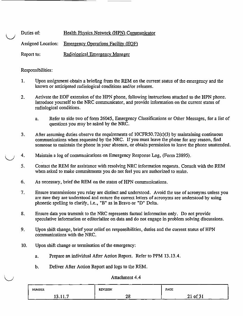
Duties of: Health Physics Network (HPN) Communicator
Assigned Location: Emergency Operations Facility (EOF)
Report to: Radiological Emergency Manager
Responsibilities:
1. Upon assignment obtain a briefing from the REM on the current status of the emergency and theknown or anticipated radiological conditions and/or releases.
2. Activate the EOF extension of the HPN phone, following instructions attached to the HPN phone.Introduce yourself to the NRC communicator, and provide information on the current status ofradiological conditions.
a. Refer to side two of form 26045, Emergency Classifications or Other Messages, for a list ofquestions you may be asked by the NRC.
3. After assuming duties observe the requirements of 10CFR50.72(c)(3) by maintaining continuouscommunications when requested by the NRC. If you must leave the phone for any reason, findsomeone to maintain the phone in your absence, or obtain permission to leave the phone unattended.
4. Maintain a log of communications on Emergency Response Log, (Form 23895).
5. Contact the REM for assistance with resolving NRC information requests. Consult with the REMwhen asked to make commitments you do not feel you are authorized to make.
6. As necessary, brief the REM on the status of HPN communications.
7. Ensure transmissions you relay are distinct and understood. Avoid the use of acronyms unless youare sure they are understood and ensure the correct letters of acronyms are understood by usingphonetic spelling to clarify, i.e., "B" as in Bravo or "D" Delta.
8. Ensure data you transmit to the NRC represents factual information only. Do not providespeculative information or editorialize on data and do not engage in problem solving discussions.
9. Upon shift change, brief your relief on responsibilities, duties and the current status of HPNcommunications with the NRC.
10. Upon shift change or termination of the emergency:
a. Prepare an individual After Action Report. Refer to PPM 13.13.4.
b. Deliver After Action Report and logs to the REM.
Attachment 4.4
NUMBER REVISION PAGE
13.11.7 28 21 of 31
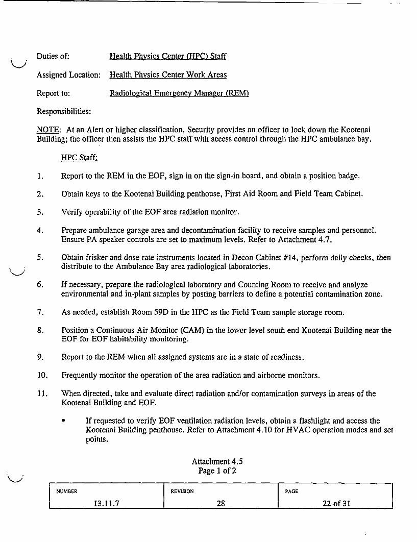
Duties of: Health Physics Center (HPC) Staff
Assigned Location: Health Physics Center Work Areas
Report to: Radiological Emergency Manager (REM)
Responsibilities:
NOTE: At an Alert or higher classification, Security provides an officer to lock down the KootenaiBuilding; the officer then assists the HPC staff with access control through the HPC ambulance bay.
HPC Staff:
1. Report to the REM in the EOF, sign in on the sign-in board, and obtain a position badge.
2. Obtain keys to the Kootenai Building penthouse, First Aid Room and Field Team Cabinet.
3. Verify operability of the EOF area radiation monitor.
4. Prepare ambulance garage area and decontamination facility to receive samples and personnel.Ensure PA speaker controls are set to maximum levels. Refer to Attachment 4.7.
5. Obtain frisker and dose rate instruments located in Decon Cabinet #14, perform daily checks, thendistribute to the Ambulance Bay area radiological laboratories.
6. If necessary, prepare the radiological laboratory and Counting Room to receive and analyzeenvironmental and in-plant samples by posting barriers to define a potential contamination zone.
7. As needed, establish Room 59D in the HPC as the Field Team sample storage room.
8. Position a Continuous Air Monitor (CAM) in the lower level south end Kootenai Building near theEOF for EOF habitability monitoring.
9. Report to the REM when all assigned systems are in a state of readiness.
10. Frequently monitor the operation of the area radiation and airborne monitors.
11. When directed, take and evaluate direct radiation and/or contamination surveys in areas of theKootenai Building and EOF.
If requested to verify EOF ventilation radiation levels, obtain a flashlight and access theKootenai Building penthouse. Refer to Attachment 4.10 for HVAC operation modes and setpoints.
Attachment 4.5Page 1 of 2
NUMBER REVISION PAGE
13.11.7 28 22 of 31
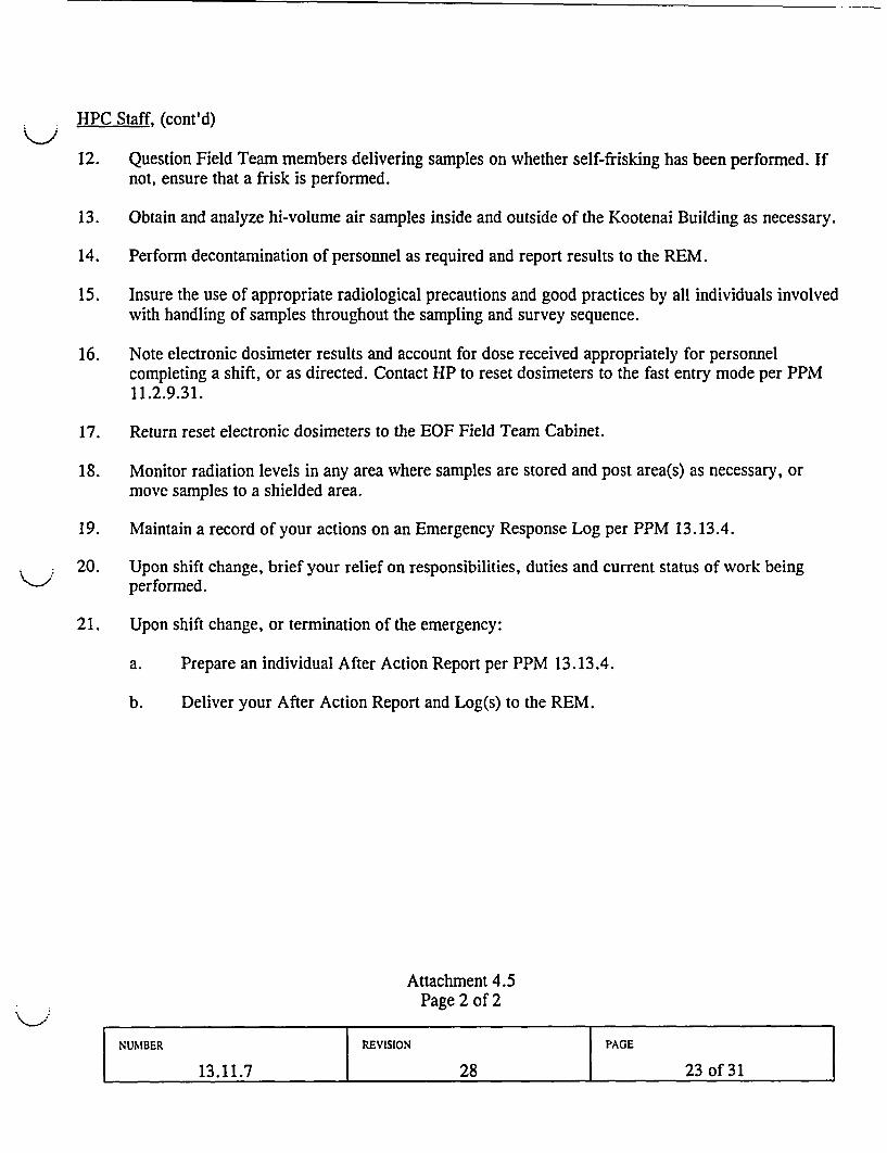
HPC Staff, (cont'd)
12. Question Field Team members delivering samples on whether self-frisking has been performed. Ifnot, ensure that a frisk is performed.
13. Obtain and analyze hi-volume air samples inside and outside of the Kootenai Building as necessary.
14. Perform decontamination of personnel as required and report results to the REM.
15. Insure the use of appropriate radiological precautions and good practices by all individuals involvedwith handling of samples throughout the sampling and survey sequence.
16. Note electronic dosimeter results and account for dose received appropriately for personnelcompleting a shift, or as directed. Contact HP to reset dosimeters to the fast entry mode per PPM11.2.9.3 1.
17. Return reset electronic dosimeters to the EOF Field Team Cabinet.
18. Monitor radiation levels in any area where samples are stored and post area(s) as necessary, ormove samples to a shielded area.
19. Maintain a record of your actions on an Emergency Response Log per PPM 13.13.4.
20. Upon shift change, brief your relief on responsibilities, duties and current status of work beingperformed.
21. Upon shift change, or termination of the emergency:
a. Prepare an individual After Action Report per PPM 13.13.4.
b. Deliver your After Action Report and Log(s) to the REM.
Attachment 4.5Page 2 of 2
NUMBER REVISION PAGE
13.11.7 28 23 of 31

HEALTH PHYSICS CENTER STAFFRADIOLOGICAL SAMPLE TRACKING INSTRUCTIONS
1. Receive, survey, sort and catalog samples as they are delivered by Environmental Field Teams.
2. Adhere to appropriate radiological precautions and good practices in the handling of samplesthroughout the sampling and survey sequence.
3. Question Field Team members delivering samples on whether self-frisking has been performed by,or under the supervision of a qualified HP member, and if not, perform a frisk.
4. For receipt and handling of PASS samples ensure that appropriate cautions are in place and that allpersonnel are properly dressed out for all aspects of survey and handling procedures.
5. Perform radiation and contamination surveys on all incoming samples. Rebag all samples which arecontaminated on the outer surface. Sort and store samples based on radiation levels to controlexposures in the ambulance bay.
6. Ensure sample identification data is on the outside of the sample bag and the date, time and surveyresults are on Sample Identification Form.
7. Place the sample in storage and note the storage location on the Sample Identification Form andenter the storage date and time on the Sample Receipt Log, page 2 of this attachment.
8. When analysis of a specific sample is requested, retrieve sample and the appropriate copies of theSample ID Form.
9. Record the new location (lab where sample is being analyzed) on the Sample ID form and the dateand time of transfer on the Sample Receipt Log.
10. Send the sample to the lab or other assigned destination with the accompanying white and canarypages.
11. Refile the pink page of the Sample Identification Form in the HP Center file.
12. When samples are returned to the storage area, retrieve Sample Identification Form from HP Centerfile.
13. Note storage location on the white, canary and pink pages and enter the new storage date and timeon the Sample Receipt Log.
14. Return the canary and pink copies to the HP Center file and return the white copy with the sampleback to storage.
Attachment 4.6Page 1 of 2
NUMBER REVISION PAGE
13.11.7 28 24 of 31
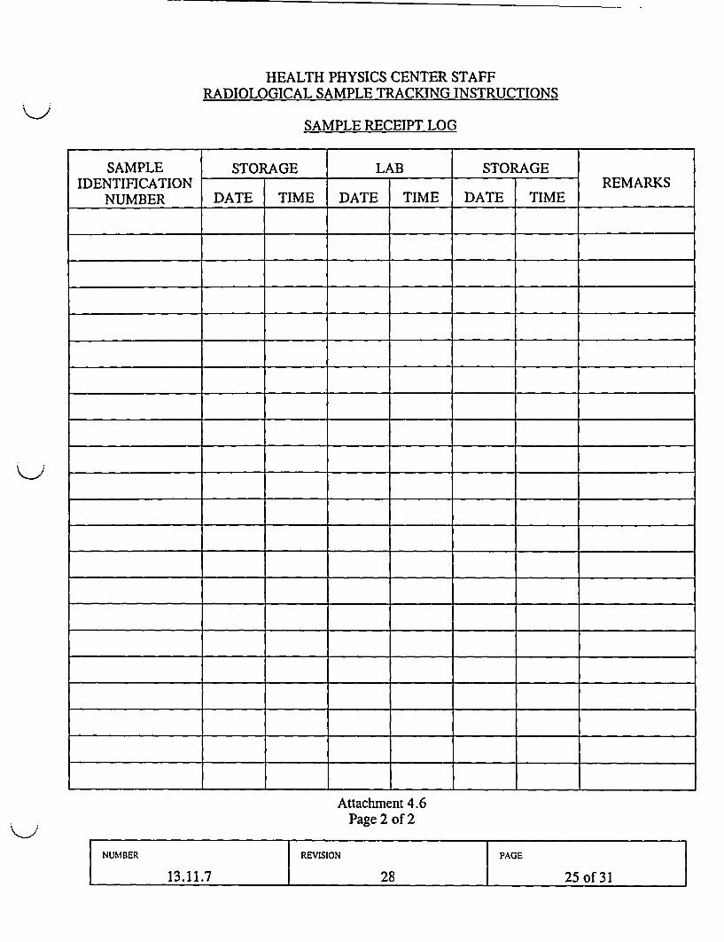
HEALTH PHYSICS CENTER STAFFRADIOLOGICAL SAMPLE TRACKING INSTRUCTIONS
SAMPLE RECEIPT LOG
SAMPLE STORAGE LAB STORAGEIDENTIFICATION REMARKS
NUMBER DATE TIME DATE TIME DATE TIME
Attachment 4.6Page 2 of 2
NUMBER REVISION PAGE
13.11.7 28 - 25 of331

TYPICAL SET-UP FOR HP CENTER RECEIVING AREA
.ROOM 59D(DE-CON AREA) FTSAMPLE
STORAGEI I .I_
ISAMPLE1 I
\- ,1
I ,- I I
SINK
I,
PROTECTIVECLOTHINGDRUM
w
0-C
PU-
rm
p |ROLLP DOOR
/ PLANT PERSONNEL, IFIPELD TEAMS. jSAMPLE
COURIERS. OFFsTE I DELIVERY/ | AGENCYPERSONNEL,
/IvLEGEND:
I ------ INDICATES WHERE TO PLACE ROPE BARRIERS
2. INDICATES WHERE TO POST SIGNS
3. INDICATES WHERE TO POST CAUTION TAPE 892z
*_Doc 200
------------------- Q
b
Attachment 4.7
NUMBER REVISION PAGE
13.11.7 28 26 of 31
RADIOLOGICAL EMERGENCY MANAGER BRIEFING GUIDELINES
NOTE: Items listed here are suggested topics for routine update briefing. Items actually selected should beused based on existing or projected plant or radiological conditions.
Radiological Emergency Manager (REM) update items:
a. Current release rate, recent trends, prognosis.
b. Offsite dose projection results and most recent follow-up messages to offsite authorities.
c. Energy Northwest (and offsite agency) field team survey results and their comparison to doseprojection model results.
d. Dose projection comparison with state or other agency results.
e. Current and forecast meteorology on wind direction, shifts.
f. Status of offsite protective action implementation.
g. EOF habitability survey results and any protective actions or safe routes necessary for emergencyworkers outside the EOF.
h. Problem areas needing resolution.
i. NRC counterpart status report (if present).
Notes:
Attachment 4.8
NUMBER REVISION PAGE
13.11.7 28 27 of331
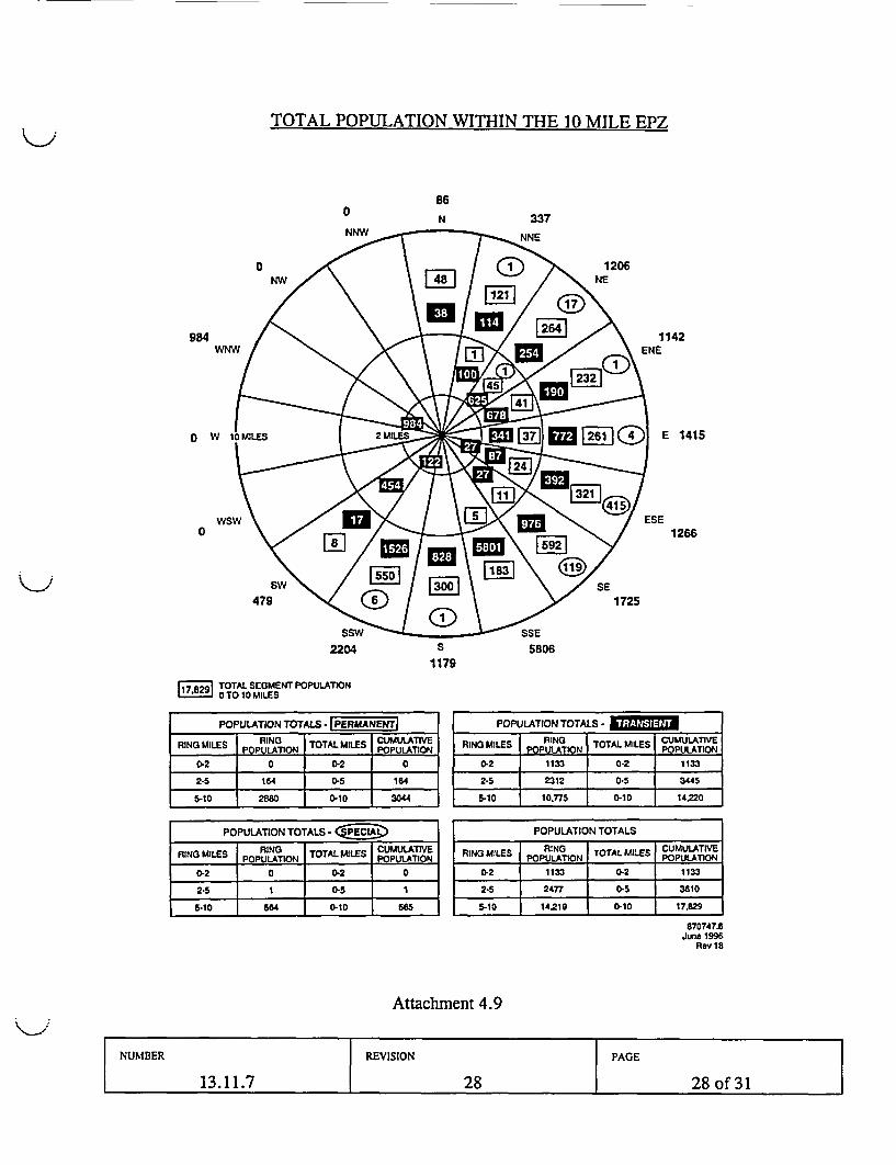
TOTAL POPULATION WITHIN THE 10 MILE EPZ
0
NNW
86
N 337
984
0 1
0
1142ENE
E 1415
ESE1266
2204 S 58061179
17.829 TOTAL SEGMENT POPULATION0 TO 10 MILES
POPULATION TOTALS* PERMANENTRIN u~s RING 1TOTAL MILES I CUMULATIVE
RIN3 MILES POPULATION TOTAL POPULATION
02 0 0.2 0
2-5 164 j 0-5 164
POPULATION TOTALS - -
RING MILES RING TOTAL MILES CUMULATIVE____ _ POUAINPOPULATION
0-2 1133 0-2 1133
2-5 2312 0-5 3445
5-10 10,775 0-10 14.2205-10 2W 1 0-10 30
POPULATION TOTALS - (!3
RING MILES POPUNATION TOTAL MILES CPUULATIOE
0-2 0 0.2 0
2-5 1 0.5 1
5-10 564 0.10 5
POPULATION TOTALS
RNG MtLES | RING TOTAL MILES | CUMULATIVERNGMILES POPULATION _ ____ POPULATION
0-2 1133 0-2 1133
2-5 2477 0-5 3610
5-10 14.219 0-10 17,B29
870747.8June 1996
Rev 18
Attachment 4.9
NUMBER REVISION PAGE
13.11.7 28 28 of331
EOF HVAC AUTOMATIC AND MANUAL OPERATION
Normal Operation:
The HVAC panel in Room 121 will indicate as follows:
AHU-1: off AHU-2: off Misc.: offEOF ISOL.: off AD4B: off SF3: lighted
MODE 1 - Kootenai Building Isolation
If outside air activity causes the intake air radiation monitor on AHU-1 to trip at 100 mR/hr,the HVAC panel in Room 121 will indicate as follows:
AHU-1: lighted AHU-2: lighted Misc.: lightedEOF ISOL.: off AD4B: off SF3: lighted
This configuration isolates the Kootenai Building and recirculates first floor air through HEPAfilters.
MODE 2 - EOF Isolation
If return air activity causes the return air radiation monitor on AHU-1 to trip at 50 mR/hr, theHVAC panel in Room 121 will indicate as follows:
AHU-1: lighted AHU-2: lighted Misc.: lightedEOF ISOL.: lighted AD4B: lighted* SF3: off
off**
In this configuration, the EOF is sealed off from the rest of the Kootenai Building. Fan SF-3recirculates EOF air through HEPA filters.
* Chem Lab exhaust hood is OFF.** Chem Lab exhaust hood is ON.
MODE 3 - EOF Stagnation
If the SF-3 return air radiation monitor trips at 50 mR/hr, SF-3 will stop and the EOF willremain isolated as in Mode 2. The SF-3 light on the Room 121 panel will be ON.
Attachment 4.10Page 1 of 2
NUMBER REVISION PAGE
13.11.7 28 29 of 31
EOF HVAC AUTOMATIC AND MANUAL OPERATION (Contd.)
MANUAL OPERATION
CAUTION: Due to the potential for airborne contamination and arearadiation, HP surveys of the following areas should be performed priorto entry.
Modes 1 & 2:
Obtain EOF HVAC key (1 F 8) from EOF key locker. Enter stairwell on 2nd floor eastside by Auditorium entrance.
At top of stairs, continue left 1800, facing east wall. Above handrail at your left aretwo radiation indicators. Above the indicators, the gray box contains the switches forModes 1 and 2.
NOTE: In the event that the auto-trip function fails to de-energize SF-3 on high radiation inthe recirculation fan plenum (Mode 3), the manual disconnect switch is available to interruptpower to this fan.
Mode 3:
Enter SF-3 fan room, room 123. Radiation indicator is inside large gray cabinet onnorth wall next to door facing Room 121. Disconnect switch for SF-3 is around otherside of fan from radiation indicator, on north wall. Throw this switch to OFF to stopSF-3.
Attachment 4.10Page 2 of 2
NUMBER REVISION PAGE
13.11.7 28 30 of 31
DOSE ASSESSMENT CENTER LEADERSHIP TRANSFER GUIDE
Transfer of MUDAC leadership from Energy Northwest to the State of Washington occurs followingconclusion of the Plume phase. The transfer signals the beginning of the ingestion pathway orintermediate phase.
Prior to the transfer, the following conditions should be met:
1. Plant conditions are stable
2. The immediate emergency has been mitigated
3. No further threat of a radioactive release exists that could exceed Protective ActionGuidelines (PAGs) to the public
4. The plume has dispersed and no longer threatens to exceed PAGs.
The following documentation should be provided to the Washington State Health Liaison during thetransfer:
1. Classification Notification Forms (CNFs) identifying PARs and notifications onPotassium Iodide (KI)
2. Emergency dose projection results
* Include both the data sheet and map projections
3. Airspace closure requests
Conduct a briefing with the Washington State Health Liaison addressing the following:
1. Status and duration of the release
2. Air sample results
3. Meteorological conditions, including wind speed
Direction: Stability:
4. Current field team deployment:
5. Offsite Protective Action Decisions (evacuations, etc.)
Attachment 4.11
NUMBER REVISION PAGE
13.11.7 28 31 of 31

DATE: 04/22/04
EDITORIAL
13. 12.20
b. If not already done by Support Manager, change the ABC switch positions onthe two Digital Call Recorders on the Support Manager's desk to MessageNumber 2. Dial 5100 and 5011 to verify that the message requests callers tostay on the line.
c. Assign team members to phone positions and provide copies ofAttachment 4.3. 1, Phone Team Member.
d. Ensure that as many phone team members as possible participate in the initialJIC staff briefing as scheduled by the JIC Manager or provided by speakerphone. If members cannot participate, provide them a briefing of theinformation covered.
e. Ensure that copies of news releases that have been issued are available to phoneteam members.
NOTE: Activation of phone lines should occur as soon as possible afterdistribution of first news release, broadcast of EBS messages, and receipt ofinformation of potential interest to the public and media. The Phone TeamSupervisor should notify the JIC Manager as soon as one or more teammembers is ready to receive calls.
f. When several team members have reported and operation is set up, activatephone lines, then report activation to the Information Manager.
g. Assign one or two members to monitor TV and radio broadcasts. See B.2.f.See also Attachment 4.2.1.
2. Ongoing Actions
CAUTION: Do NOT display Protective ActionRecommendations to the Phone Team. Display onlyProtective Action Decisions.
a. Record on white board key information from news conferences, EmergencyAlerting System messages, or other official sources needed by team membersto respond to phone inquiries, then, as necessary, provide hard copy to phoneteam members. Avoid details that should not be included in Phone Teamresponses. Ensure all times are in civilian, not military, format.
b. When possible, observe and evaluate TV or radio news broadcasts formisinformation and promptly report misinformation to Information Manager,giving station, time, and newscaster.
c. Conduct team member briefings whenever events change or new informationhas developed. If desired, deactivate'all but one phone for short periods oftime to conduct the briefing.
Attachment 4.3Page 2 of 5
PROCEDURE NUMBER REVISION PAGE
13.12.20 4 16 of 22