plasma-assisted cleaning by metastable-atom...
TRANSCRIPT

Plasma-assisted cleaning by metastable-atom neutralizationWayne M. Lytle, Daniel Andruczyk, and David N. Ruzic Citation: Journal of Vacuum Science & Technology B 31, 011603 (2013); doi: 10.1116/1.4770500 View online: http://dx.doi.org/10.1116/1.4770500 View Table of Contents: http://scitation.aip.org/content/avs/journal/jvstb/31/1?ver=pdfcov Published by the AVS: Science & Technology of Materials, Interfaces, and Processing Articles you may be interested in Surface oxidation of GaN(0001): Nitrogen plasma-assisted cleaning for ultrahigh vacuum applications J. Vac. Sci. Technol. A 32, 051401 (2014); 10.1116/1.4886956 Cleaning of diamond nanoindentation probes with oxygen plasma and carbon dioxide snow Rev. Sci. Instrum. 80, 126102 (2009); 10.1063/1.3266972 Cleaning of extreme ultraviolet lithography optics and masks using 13.5 nm and 172 nm radiation J. Vac. Sci. Technol. B 23, 247 (2005); 10.1116/1.1849220 Formation and removal of composite halogenated silicon oxide and fluorocarbon films deposited on chamberwalls during plasma etching of multiple film stacks J. Vac. Sci. Technol. B 20, 1939 (2002); 10.1116/1.1502698 Mechanical analysis of the PLASMAX particle removal process for optical and next-generation lithography masks J. Vac. Sci. Technol. B 18, 3221 (2000); 10.1116/1.1314369
Redistribution subject to AVS license or copyright; see http://scitation.aip.org/termsconditions. Download to IP: 128.174.163.244 On: Mon, 13 Oct 2014 23:54:17

Plasma-assisted cleaning by metastable-atom neutralization
Wayne M. Lytle,a) Daniel Andruczyk,b) and David N. RuzicDepartment of Nuclear, Plasma and Radiological Engineering, Center for Plasma Materials Interaction,University of Illinois, Illinois 61801
(Received 2 April 2012; accepted 26 November 2012; published 26 December 2012)
Plasma-assisted cleaning by metastable atomic neutralization (PACMAN) is a process that can
clean hydrocarbon from extreme ultraviolet photo masks and dissolve hydrocarbon particles. It was
developed with semiconductor manufacturing and cleaning in mind. The PACMAN process works
by utilizing helium metastable atoms to break apart the contamination to be cleaned. As helium
metastables interact with the contaminant surface, bonding electrons from the surface are “stolen”
by the metastable helium resulting in “holes” where a bonding electron used to be. In this way, the
structure of the contamination is compromised and allows for the removal either through desorption
of CxHy molecules or by chain scission of the hydrocarbon backbone. A model of the helium
metastable density within the processing chamber has been developed in addition to experimental
measurements of the metastable density at the sample surface. Cleaning efficiency has been linked
to both helium metastable density as well as electric field in the plasma sheath. Electric field
calculations in the plasma sheath reveal that an electric field pointing into the plasma is needed for
achieving high cleaning rates of hydrocarbons since it pins the holes that are created to the surface
and stops the hydrocarbon bonds from re-forming. Operating the PACMAN process in this fashion
allows for cleaning rates of approximately 1.2� 107 6 5.1� 105 nm3/min from a particle without
causing damage to the surrounding structure of the sample being cleaned. Carbon contamination in
the form of carbon films on lithographic material has been shown to clean at rates of approximately
11.4 6 0.3 nm/min. VC 2013 American Vacuum Society. [http://dx.doi.org/10.1116/1.4770500]
I. INTRODUCTION
One of the critical issues still facing the implementation
of extreme ultraviolet lithography (EUVL) into mainstream
manufacturing for integrated circuit production is cleanli-
ness. The 13.5 nm photons are easily absorbed by many spe-
cies; these include dust, thin film layers, and other debris
present in the photons path. Carrying out EUVL inside a
vacuum helps reduce the amount of photon loss; however,
contamination is always unavoidable. Traditional cleaning
methods employ the use of wet chemicals to etch contami-
nants off of a surface; however, this is limited in the submi-
cron range of contaminant particles due to the lack of
transport of sufficient liquid chemicals to the surface in order
to achieve satisfactory particle removal.
According to the International Technology Road Map for
Semiconductors (ITRS), the photomask must be particle free
at inspection above 30 nm. When analyzing the ability of tra-
ditional methods to meet the cleaning needs set forth by the
ITRS, these methods fall short and often add more contami-
nation to the surface.
Metastable atoms and their interaction with surfaces have
been studied for several different purposes: metastable
probes, metastable beam lithography, and their role in
desorbing gas species from surfaces.1–3 There are two pri-
mary interactions that can occur when a metastable interacts
with a surface: resonance ionization followed by Auger neu-
tralization (AN) on a conductor or Penning ionization (PI)
which is also known as Auger deexcitation (AD) on an insu-
lator. When a metastable atom collides with an ordinary
metal, the 2S electron of the helium metastable tunnels into
an empty level in the surface of the metal forming a helium
ion. This process is called resonance ionization. This helium
ion is then neutralized by an electron from the surface fol-
lowed simultaneously by the emission of another surface
electron. This process is called Auger neutralization.4
However, on an insulator, resonance ionization is sup-
pressed because the 2S level of the helium metastable falls
within the energy gap of the insulator. Thus, as the helium
metastable interacts with the surface, an electron from an
occupied orbital from the surface will transfer to the helium
metastable with the subsequent ejection of the 2S electron.4
The two interactions of the helium metastable with a surface
can be seen in Fig. 1.
In a study by Kurahashi and Yamauchi5 examining de-
sorption of hydrogen from a surface, they conclude that if
the helium metastable extracts a bonding electron from the
hydrogen-surface bond, the bond becomes weaker. As the
bond becomes weaker, the equilibrium bond distance length-
ens. This weakening and lengthening of the bond changes
the potential of the hydrogen-surface bond and the hydrogen
can desorb from the surface.5 A similar method is theorized
to be the cause for the helium metastable cleaning of organic
material.
With all this in mind, a new cleaning method has been
developed to compliment these traditional methods such as
using a low-energy hydrogen plasma. A plasma based
method to clean organic contaminants from lithographic
materials is presented in this paper and demonstrates the re-
moval of hydrocarbon particles (polystyrene latex particles
in this instance) in the range of 30–50 nm as well as the
a)Present address: Intel, Hillsboro, OR 97124.b)Electronic mail: [email protected]
011603-1 J. Vac. Sci. Technol. B 31(1), Jan/Feb 2013 2166-2746/2013/31(1)/011603/9/$30.00 VC 2013 American Vacuum Society 011603-1
Redistribution subject to AVS license or copyright; see http://scitation.aip.org/termsconditions. Download to IP: 128.174.163.244 On: Mon, 13 Oct 2014 23:54:17

removal of 30 nm carbon film layers on silicon wafers. This
method is called plasma-assisted cleaning by metastable
atom neutralization (PACMAN).
II. EXPERIMENT
The PACMAN experimental setup consists of a main
chamber that houses the substrate. A m¼ 0 helicon source is
used to produce the helium plasma. Helium is used due to
the fact that it has a low sputtering threshold on lithographic
material due to its low mass and no chemical interactions.
The substrate can be DC biased in either a steady state or a
pulsed mode. The system is capable of processing a full
150 mm� 150 mm wafer. A load lock is used to load and
remove the sample from the main chamber. This allows the
integrity of the vacuum to be maintained and also for speed
of processing the samples. A schematic of the PACMAN
chamber is shown in Fig. 2.
Particle contamination is done by polystyrene latex par-
ticles obtained from Duke Scientific in aqueous solution, the
chemical formula is C8H8. The test surface is made from N-
type (phosphorus doped) silicon made by Addison Engineer-
ing. The wafers have a diameter of 25 mm and a resistivity
from 1 to 10 Xcm.
The removal rate is measured by taking an SEM of a
region of interest on the wafer after the particles have been
deposited. The diameter of particles is measured and a mini-
mum of four particles are used. After the wafer has been
processed through PACMAN, another SEM is taken postpro-
cessing of the same region and the diameter of the particles
measured. The difference between the particle diameters
allows a removal rate to be determined.
III. THEORY
Typically, when plasma is used in experiments, only the
ions and electrons play an important role. However, ener-
getic neutrals and metastables form a large component of
any plasma. A metastable is an atom that is in an energy
state that is quantum mechanically forbidden through
FIG. 1. Diagram for the energy transfer of metastable atoms to surfaces. (a)
PI or AD on an insulator. (b) Resonance ionization on a metal. (c) Auger-
neutralization on a metal (Ref. 4).
FIG. 2. (Color online) PACMAN chamber. The m¼ 0 helicon plasma source is in black on the right. Directly below it is the main chamber that holds the substrate.
To the left is the load lock mechanism that allows the sample from being moved in and out without breaking vacuum. All dimensions shown are in meters.
011603-2 Lytle, Andruczyk, and Ruzic: Plasma-assisted cleaning by metastable atom neutralization 011603-2
J. Vac. Sci. Technol. B, Vol. 31, No. 1, Jan/Feb 2013
Redistribution subject to AVS license or copyright; see http://scitation.aip.org/termsconditions. Download to IP: 128.174.163.244 On: Mon, 13 Oct 2014 23:54:17
conservation of momentum to decay into the ground state.
Helium has two metastable states: a singlet, 21S, and a tri-
plet, 23S. The energy level of the singlet is E21S¼ 20.6 eV
and the triplet E23S¼ 19.8 eV.6,7
The PACMAN process is based on three important mech-
anisms. One is the metastable density which plays the impor-
tant role of introducing electronic holes in the surface by
breaking bonds, second is the electric field, which maintains
the broken bonds at the surface of the particle, and third the
electron flux to the surface keeps broken bonds from
reforming.
A. Metastables
The density of helium metastable atoms in the plasma can
be modeled through a collisional radiative model. In this
type of model, it is possible to track the population and
decay of higher energy levels of the helium atom that would
result in a metastable atom in the 2s singlet or triplet levels.
The number of higher energy states to track depends on the
complexity necessary to capture the major collisional and
radiative processes. The extent to which the higher energy
levels will be used to determine population states of the
lower energy levels needs to be limited to some finite value
based on the probability of the reactions. For this collisional
radiative model, states up to and including the 3s and 3d
state are used to calculate the population of the excited levels
in the helium plasma.8
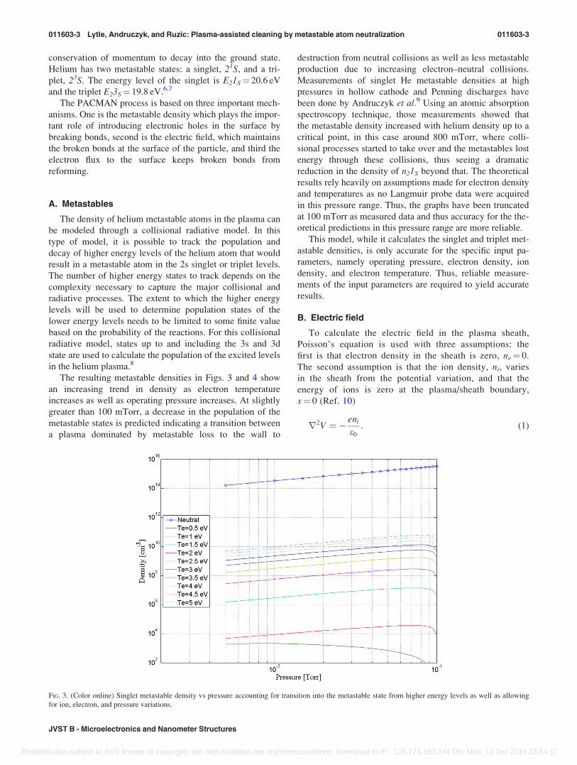
The resulting metastable densities in Figs. 3 and 4 show
an increasing trend in density as electron temperature
increases as well as operating pressure increases. At slightly
greater than 100 mTorr, a decrease in the population of the
metastable states is predicted indicating a transition between
a plasma dominated by metastable loss to the wall to
destruction from neutral collisions as well as less metastable
production due to increasing electron–neutral collisions.
Measurements of singlet He metastable densities at high
pressures in hollow cathode and Penning discharges have
been done by Andruczyk et al.9 Using an atomic absorption
spectroscopy technique, those measurements showed that
the metastable density increased with helium density up to a
critical point, in this case around 800 mTorr, where colli-
sional processes started to take over and the metastables lost
energy through these collisions, thus seeing a dramatic
reduction in the density of n21S beyond that. The theoretical
results rely heavily on assumptions made for electron density
and temperatures as no Langmuir probe data were acquired
in this pressure range. Thus, the graphs have been truncated
at 100 mTorr as measured data and thus accuracy for the the-
oretical predictions in this pressure range are more reliable.
This model, while it calculates the singlet and triplet met-
astable densities, is only accurate for the specific input pa-
rameters, namely operating pressure, electron density, ion
density, and electron temperature. Thus, reliable measure-
ments of the input parameters are required to yield accurate
results.
B. Electric field
To calculate the electric field in the plasma sheath,
Poisson’s equation is used with three assumptions: the
first is that electron density in the sheath is zero, ne¼ 0.
The second assumption is that the ion density, ni, varies
in the sheath from the potential variation, and that the
energy of ions is zero at the plasma/sheath boundary,
x¼ 0 (Ref. 10)
r2V ¼ � eni
e0
: (1)
FIG. 3. (Color online) Singlet metastable density vs pressure accounting for transition into the metastable state from higher energy levels as well as allowing
for ion, electron, and pressure variations.
011603-3 Lytle, Andruczyk, and Ruzic: Plasma-assisted cleaning by metastable atom neutralization 011603-3
JVST B - Microelectronics and Nanometer Structures
Redistribution subject to AVS license or copyright; see http://scitation.aip.org/termsconditions. Download to IP: 128.174.163.244 On: Mon, 13 Oct 2014 23:54:17

Applying the assumption that ne¼ 0 in the plasma sheath,
where e is the elementary charge, ion density variation in the
plasma sheath varies according to (Ref. 11)
niðxÞ ¼ji;0
e� 2 eV
mi
� ��1=2
; (2)
where Ji,0 is the constant ion current and mi is the ion mass.
One could continue on to calculate the potential versus
location in the plasma sheath; however, knowing that
E¼�(dV/dx), the electric field in the plasma sheath has
been derived without making the assumption that Vplasma
�Vwall is�Te. The electric field in the plasma sheath region
is thus
E ¼ �2ji;0e0
� �1=22e
mi
� ��1=4
ðjVjÞ1=4•6ðVÞ: (3)
The value of potential, V, used is the potential with
respect to plasma potential, which is found by Vwall,bias
�Vplasma. The term 6(V) is used to denote the direction of
the electric field. When the electric field points from the
plasma into the surface [when V in Eq. (3) is negative], this
is considered a positive electric field. When the electric
field points from the surface into the plasma [when V in Eq.
(3) is positive], this is considered a negative electric field.
One conclusion apparent from the result derived in Eq. (3)
is that the electric field does not depend on the location
within the sheath. Thus, the electric field is considered con-
stant throughout the plasma sheath.
The electric field directed into the surface encounters a
perturbation when there is a particle in the way. If the parti-
cle was a conductor, it would set up an internal field to can-
cel the applied field from the plasma sheath due to the ability
of mobile charge carriers to adjust in the conductor.12,13
However, a dielectric particle can only partially cancel the
applied field. To model the electric field inside the dielectric
particle, one can solve Laplace’s equation for the potential
inside and outside of the sphere as a boundary layer problem.
The resulting equation is
~E ¼ 3
er þ 2~E0: (4)
This result then shows that the electric field inside the
particle is uniform and reduced in magnitude compared to
the original electric field, ~E0.
C. Electron flux
Electron flux to the surface is dependent on the densities
of electrons in the plasma as well as the velocity of the elec-
trons. Assuming a Maxwellian energy distribution for the
electrons in the plasma assisted cleaning by electrostatics
helicon plasma source, the flux of electrons to the surface is
given as10
Ce ¼1
4neve; (5)
where ne and ve are the electron density and velocity,
respectively.
IV. RESULTS
A. Particle removal versus time
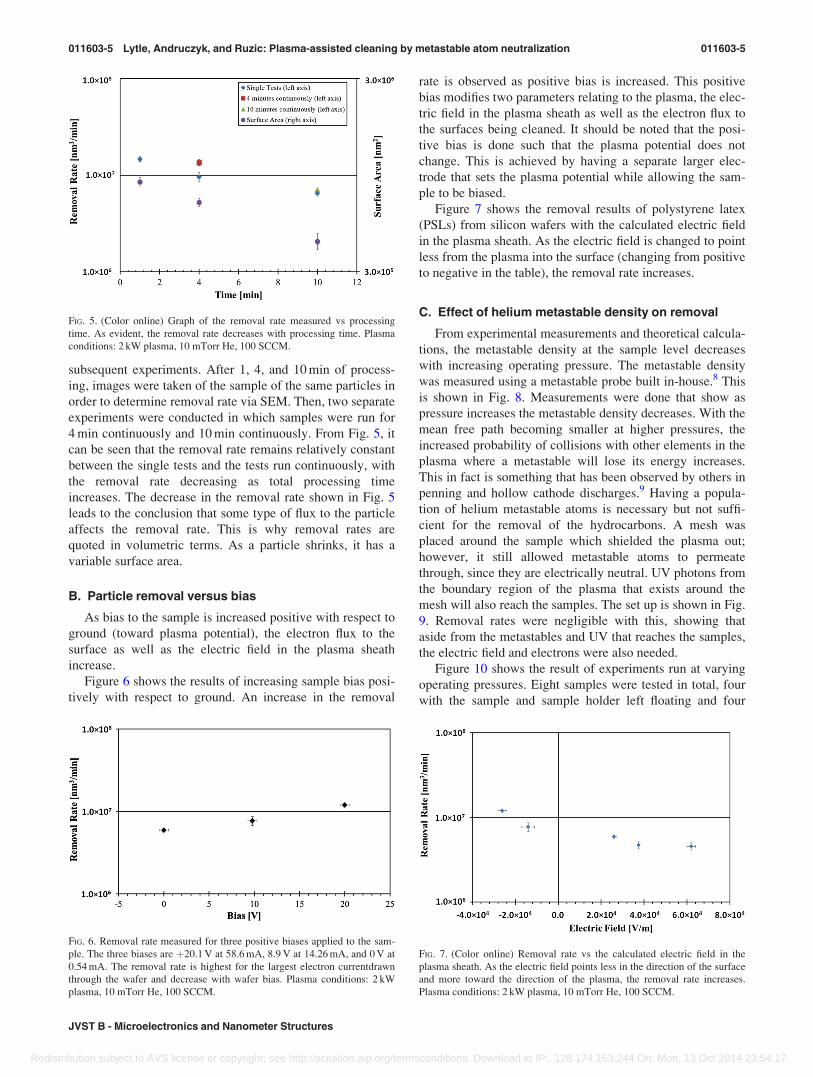
Figure 5 shows the time evolution of particle removal in a
step wise fashion as well as the surface area of the particle.
The points labeled “single tests” were run for 1 min incre-
ments with an air interval of at least 5 min between
FIG. 4. (Color online) Triplet metastable density vs pressure accounting for transitions into the metastable state from higher energy levels as well as allowing
for ion, electron, and pressure variations.
011603-4 Lytle, Andruczyk, and Ruzic: Plasma-assisted cleaning by metastable atom neutralization 011603-4
J. Vac. Sci. Technol. B, Vol. 31, No. 1, Jan/Feb 2013
Redistribution subject to AVS license or copyright; see http://scitation.aip.org/termsconditions. Download to IP: 128.174.163.244 On: Mon, 13 Oct 2014 23:54:17
subsequent experiments. After 1, 4, and 10 min of process-
ing, images were taken of the sample of the same particles in
order to determine removal rate via SEM. Then, two separate
experiments were conducted in which samples were run for
4 min continuously and 10 min continuously. From Fig. 5, it
can be seen that the removal rate remains relatively constant
between the single tests and the tests run continuously, with
the removal rate decreasing as total processing time
increases. The decrease in the removal rate shown in Fig. 5
leads to the conclusion that some type of flux to the particle
affects the removal rate. This is why removal rates are
quoted in volumetric terms. As a particle shrinks, it has a
variable surface area.
B. Particle removal versus bias
As bias to the sample is increased positive with respect to
ground (toward plasma potential), the electron flux to the
surface as well as the electric field in the plasma sheath
increase.
Figure 6 shows the results of increasing sample bias posi-
tively with respect to ground. An increase in the removal
rate is observed as positive bias is increased. This positive
bias modifies two parameters relating to the plasma, the elec-
tric field in the plasma sheath as well as the electron flux to
the surfaces being cleaned. It should be noted that the posi-
tive bias is done such that the plasma potential does not
change. This is achieved by having a separate larger elec-
trode that sets the plasma potential while allowing the sam-
ple to be biased.
Figure 7 shows the removal results of polystyrene latex
(PSLs) from silicon wafers with the calculated electric field
in the plasma sheath. As the electric field is changed to point
less from the plasma into the surface (changing from positive
to negative in the table), the removal rate increases.
C. Effect of helium metastable density on removal
From experimental measurements and theoretical calcula-
tions, the metastable density at the sample level decreases
with increasing operating pressure. The metastable density
was measured using a metastable probe built in-house.8 This
is shown in Fig. 8. Measurements were done that show as
pressure increases the metastable density decreases. With the
mean free path becoming smaller at higher pressures, the
increased probability of collisions with other elements in the
plasma where a metastable will lose its energy increases.
This in fact is something that has been observed by others in
penning and hollow cathode discharges.9 Having a popula-
tion of helium metastable atoms is necessary but not suffi-
cient for the removal of the hydrocarbons. A mesh was
placed around the sample which shielded the plasma out;
however, it still allowed metastable atoms to permeate
through, since they are electrically neutral. UV photons from
the boundary region of the plasma that exists around the
mesh will also reach the samples. The set up is shown in Fig.
9. Removal rates were negligible with this, showing that
aside from the metastables and UV that reaches the samples,
the electric field and electrons were also needed.
Figure 10 shows the result of experiments run at varying
operating pressures. Eight samples were tested in total, four
with the sample and sample holder left floating and four
FIG. 5. (Color online) Graph of the removal rate measured vs processing
time. As evident, the removal rate decreases with processing time. Plasma
conditions: 2 kW plasma, 10 mTorr He, 100 SCCM.
FIG. 6. Removal rate measured for three positive biases applied to the sam-
ple. The three biases are þ20.1 V at 58.6 mA, 8.9 V at 14.26 mA, and 0 V at
0.54 mA. The removal rate is highest for the largest electron currentdrawn
through the wafer and decrease with wafer bias. Plasma conditions: 2 kW
plasma, 10 mTorr He, 100 SCCM.
FIG. 7. (Color online) Removal rate vs the calculated electric field in the
plasma sheath. As the electric field points less in the direction of the surface
and more toward the direction of the plasma, the removal rate increases.
Plasma conditions: 2 kW plasma, 10 mTorr He, 100 SCCM.
011603-5 Lytle, Andruczyk, and Ruzic: Plasma-assisted cleaning by metastable atom neutralization 011603-5
JVST B - Microelectronics and Nanometer Structures
Redistribution subject to AVS license or copyright; see http://scitation.aip.org/termsconditions. Download to IP: 128.174.163.244 On: Mon, 13 Oct 2014 23:54:17

samples under a constant þ9.8 V bias. The floating experi-
ments show a general decrease in removal rate as the operat-
ing pressure is increased in the vacuum chamber. The
experiments with a þ9.8 V bias to the sample show a
decrease in removal rate with increasing operating pressure.
Note that the main chamber is remote from the plasma
source, and its walls stay at room temperature, so we feel
confident that the neutral gas density is proportional to the
pressure.
To explain the behavior of the removal results in Fig. 10,
several parameters between the plasma and sample interac-
tion change. First, consider the floating sample data. The
electric field of the plasma for the “floating” cases points
from the plasma into the sample, with the electric field at
5 mTorr calculated as 3.59� 104 V/m, at 10 mTorr calcu-
lated as 3.70� 104 V/m, and at 50 mTorr calculated as
2.63� 104 V/m. As shown in the Sec. IV B, an electric field
that points from the plasma into the sample and is increasing
should decrease the removal rate. An increase of the electric
field pointing from the plasma into the sample is what is cal-
culated from the 5 to 10 mTorr case, and a reduction in the
cleaning rate is also observed. However, at 50 mTorr, the
electric field pointing from the plasma into the sample
decreases, but a decrease in the removal rate is still
observed. One item to note is that plasma density measured
with a Langmuir probe at the sample level does decrease
from 10 to 50 mTorr. For increasing pressures up to 100
mTorr, plasma density does continue to decrease as well as
metastable density. From the result of the analysis of the
floating sample data in Fig. 10, the conclusion is drawn that
the decrease in the removal rate seen is due to a decrease in
the plasma density (electron flux) as well as metastable den-
sity versus increasing operating pressure.
Considering the “with bias” data in Fig. 6, a þ9.8 6 0.5 V
bias is applied to the sample. From the trend observed in
Fig. 6 for the data with bias, it is concluded that even though
the helium metastable density decreases with increasing
operating pressure, it is still of sufficient density that when a
sample bias and thus increased electron current draw is used,
removal rate does not decrease appreciably for increasing
operating pressure up to 50 mTorr.
D. Effect of ion flux
Sputtering of a material is due to the incident ion flux
being able to remove atoms from the top surface. An experi-
ment involving an electromagnet, schematically shown in
Fig. 11, was able to select ions to the sample while removing
electrons, was used to study the effect the ions had on re-
moval. With higher energy ions selected, a removal rate of
4.6� 106 6 1.7� 105 nm3/min is measured. As the energy
decreases, the removal rate starts to increase. Eventually
with no ions present on the sample, the removal rate was
very high 1.2� 107 6 1.1� 105 nm3/min.
A couple mechanisms account for this trend that is seen.
Metastable atoms were still present when the ions were inci-
dent on the sample. First is that the helium ions have a low
sputtering rate and second they do liberate hydrogen out of
the hydrocarbon lattice; thus a carbon layer is formed which
does not allow the metastables to have as much of an impact
since the energy required to break the bonds is higher. The
removal slows down and the rate is reduced. With no ions
FIG. 8. (Color online) He metastable measurements with increasing pressure.
The decrease in the metastable density is from energy loss through collisions
with other species in the plasma and background gas. Plasma conditions:
2 kW plasma, 100 SCCM.
FIG. 9. (Color online) Mesh set up to screen out the ions and electron from
the sample; it only allowed the metastable to penetrate into the mesh and
onto the sample. With metastables only, a negligible removal rate was
observed.
FIG. 10. (Color online) Removal rate vs operating pressure. A decrease in re-
moval rate is observed with increasing pressure.
011603-6 Lytle, Andruczyk, and Ruzic: Plasma-assisted cleaning by metastable atom neutralization 011603-6
J. Vac. Sci. Technol. B, Vol. 31, No. 1, Jan/Feb 2013
Redistribution subject to AVS license or copyright; see http://scitation.aip.org/termsconditions. Download to IP: 128.174.163.244 On: Mon, 13 Oct 2014 23:54:17

there, the metastables are able to break the C–H bonds much
more easily.
The reduced removal rate due to the carbon bonds has
been seen in experiments involving a carbon film. At Illinois,
a carbon film, approximately 22 nm in thickness, was grown
on a silicon substrate. This was a carbon film with few
hydrogen bonds, similar to what has been described above
with the ions knocking out the hydrogen’s and leaving a
pure carbon surface. With the application of the PACMAN
process (2 kW at 10 mTorr) for 1 min, a cleaning rate of the
carbon film of 11.4 nm/min was achieved, shown in Fig. 12.
Compare this to results if only PACMAN and sputtering
yields calculated by stopping and range of ions in matter are
used for 70 eV He on C at normal incidence, the removal
rate from sputtering alone is at most 6 nm/min and likely
much lower. A more sophisticated code, TriDyn,14 gives an
eight times smaller sputtering yield and thus a removal rate
of �0.75 nm/min. Increasing negative bias, and thus increas-
ing the sputtering only, increases removal yield slightly.8 In
addition, ion sputtering alone takes the spherical particles
and flattens them as they shrink from the top down. In these
experiments, particles were seen to retain their spherical
shapes as their radii grow smaller and eventually disappear.
V. DISCUSSION
There are two main ideas to take from the results pre-
sented in Sec. IV. The first is that the decrease in removal
rate observed versus increasing operating pressure is a com-
bination of metastable density change, plasma density (and
thus electron flux) changing, as well as electric field chang-
ing. The second is that an applied bias to the sample will
increase the removal rate seen with increasing operating
pressure compared to the removal rate of a floating sample.
Two experiments were conducted to test for the removal
of PSLs without plasma interacting with the sample but
FIG. 11. Ion flux experiment; this showed that by removing ions from the
sample, the removal rate was significantly increased.
FIG. 12. (Color online) Images show the result of cleaning a carbon sample
with the standard PACMAN cleaning technique. Carbon thickness was (a)
22 nm and was cleaned for 1 min. The resulting thickness was (b) 10.6 nm.
A cleaning rate of �11.4 6 3 nm/min was achieved.
FIG. 13. (Color online) SEM images of the PACMAN process at work.
Image (a) shows a surface with pellicles on the surface. Image (b) shows the
same surface after 10 min of treatment. The large objects in the center are
some other debris and used as a reference. Plasma conditions: 2 kW plasma,
10 mTorr He.
011603-7 Lytle, Andruczyk, and Ruzic: Plasma-assisted cleaning by metastable atom neutralization 011603-7
JVST B - Microelectronics and Nanometer Structures
Redistribution subject to AVS license or copyright; see http://scitation.aip.org/termsconditions. Download to IP: 128.174.163.244 On: Mon, 13 Oct 2014 23:54:17

while the sample was under a positive bias and drawing elec-
tron flux. A plasma-blocking mesh was used to block the
plasma from reaching the lower half of the chamber while
allowing for the helicon plasma source to operate normally.
Tested were a þ5.2 6 0.5 V bias drawing 0.4 6 0.1 mA of
current and a þ9.8 6 0.5 V bias drawing 0.8 6 0.1 mA of
current. Both experiments showed a negligible removal rate.
The combination of the mesh setup is 4.7% transparent, so a
reduced cleaning rate, if any would be expected, since meta-
stable production from the source region would also have to
diffuse to the wafer. In order to achieve a higher removal
rate to test whether or not particle removal occurs with he-
lium metastables and a positive bias, an indirect plasma-
based method of helium metastable production or other
source would be needed that does not require for the plasma
to be screened out, which ultimately limits the metastable
throughput. Such a design could likely be accomplished with
similar technology to an ion or electron gun.
In Fig. 6, the current drawn for the grounded sample
(þ0 V bias) and sample holder was 0.54 mA which is on the
same order as the current drawn in the positive bias removal
tests with the plasma-blocking mesh in place. This leads to
the conclusion that electron flux alone in a 10 mTorr helium
environment does not lead to particle removal and it is the
electric field pointing toward the plasma that keeps holes at
the surface and bonds broken. The right-most two points in
Fig. 6 are at potentials above the plasma potential thus hav-
ing a electric field which keeps holes at the surface. These
are also the points of higher removal.
In Fig. 13, SEM images have been taken to show the
actual removal of the pellicles from the surface. The top
image shows the silicon surface with polystyrene on the sur-
face. The large object on the left hand side is used is some
silicon particle and is used as a reference. The bottom image
shows the same surface after having been run through the
PACMAN process for 10 min. It is clear to see that the par-
ticles have been removed from the surface.
Table I summarizes the separate components of the
plasma and their effect on the removal of contaminants.
Note that the plasma and gas is optically thick for UV pho-
tons so their effect is small.
VI. SUMMARY AND CONCLUSIONS
The PACMAN cleaning technique removes contaminants
from the surface through a combination of helium metastable
impacts, electric field effects, and electron flux to the surface.
As helium metastables interact with the surface, they create
electronic “holes” in the surface. To limit diffusion of these
holes into the bulk of the contaminant, an electric field pointing
from the surface of the contaminant into the plasma is neces-
sary to maintain the holes near the surface of the contaminant
so volatilization of the particle can be achieved. Electron flux
to the surface helps maintain the broken bonds from reforming,
allowing for the continued removal of the particle.
The removal results provide clear evidence that the varia-
bles of helium metastable density, electron flux, and electric
field in the plasma sheath region are important parameters
needed in order to achieve removal of the polystyrene latex
nanoparticles. Through sample bias and plasma source power,
the above parameters can be varied in order to change the rate
of particulate removal seen in this investigation.
The removal rate of contaminants is observed to decrease
with processing time. As the contaminant is being removed
and becoming smaller, the surface area of the particle
decreases. Without any modification to either the metastable
helium flux or electron flux, the number of metastables and
electrons interacting with the contaminant decreases thus
leading to a theoretical decrease in the removal rate.
The conclusion that eliminating ions from the sample is
beneficial for the PACMAN cleaning technique is derived
from the experiments involving sample bias, as increasing
the bias positively with respect to ground toward plasma
potential yields a higher removal rate.
It was shown that modifying the electric field through the
application of positive bias to the sample creating an electric
field that points from the surface being cleaned into the
plasma yields a higher removal rate.
From experiments that utilized electron flux only in a he-
lium metastable environment, the conclusion is drawn that
just electron bombardment of the sample is not responsible
for the removal of contaminants. Also, the density of helium
metastable atoms in the plasma was shown to affect the re-
moval rate.
ACKNOWLEDGMENTS
The authors would like to acknowledge Sematech, Inc.,
who sponsored the work through contract agreement
#402106NY, Mod 3, and project #LITH184.
1N. Miura and J. Hopwood, Rev. Sci. Instrum. 80, 113502 (2009).2A. Bard, K. K. Berggren, J. L. Wilbur, J. D. Gillaspy, S. L. Rolston, J. J.
McClelland, W. D. Phillips, M. Prentiss, and G. M. Whitesides, J. Vac.
Sci. Technol. B 15, 1805 (1997).
TABLE I. Overview of the components of the plasma and their respective effect on the removal mechanism.
Component Comment
Processing time Removal rate vs time decreases with time, since the surface area decreases
Electric field Decreasing Efield into surface raises removal rate; keeping holes at the surface increases removal
Electron flux Electron flux alone does not provide removal
Ions Elimination of ions altogether increases the removal of rate by not densifying the surface
Metastables and UV Metastable and UV flux alone does not provide removal
Temperature Temperature is a byproduct of plasma interaction, but temperature alone does not increase removal
011603-8 Lytle, Andruczyk, and Ruzic: Plasma-assisted cleaning by metastable atom neutralization 011603-8
J. Vac. Sci. Technol. B, Vol. 31, No. 1, Jan/Feb 2013
Redistribution subject to AVS license or copyright; see http://scitation.aip.org/termsconditions. Download to IP: 128.174.163.244 On: Mon, 13 Oct 2014 23:54:17

3M. Kurahashi and Y. Yamauchi, Phys. Rev. Lett. 84, 4725 (2000).4N. Ueno, H. Yasufuku, S. Kera, K. K. Okudaira, and Y. Harada, “Surface
imaging using electrons excited by metastable-atom impacts,” Lecture
Notes in Physics, New York then Berlin (2002), pp. 131–144.5M. Kurahashi and Y. Yamauchi, Surf. Sci. 454, 300 (2000).6S. Sasaki, S. Takamura, S. Watanabe, S. Masuzaki, T. Kato, and
K. Kadota, Rev. Sci. Instrum. 67, 3521 (1996).7W. Sesselmann, B. Woratschek, J. Kuppers, G. Ertl, and H. Haberland,
Phys. Rev. B 35, 1547 (1987).8W. Lytle, “Removal of organic contaminants from lithographic materials,”
Ph.D. dissertation (University of Illinois, 2011).
9D. Andruczyk, P. X. Feng, B. W. James, and J. Howard, Plasma Sources
Sci. Technol. 11, 426 (2002).10D. N. Ruzic, Electric Probes for Low Temperature Plasmas (American
Vacuum Society, New York, 1994).11A. A. Lieberman and A. J. Lichtenberg, Principles of Plasma Discharges
and Materials Processing (John Wiley and Sons, Inc., New York, 1994).12D. J. Griffths, Introduction to Electrodynamics (Prentice Hall, NJ, 1999).13M. L. Abell and J. P. Braselton, Modern Differential Equations: Theory,
Applications, Technology (Harcourt Brace College, Fort Worth, 1995).14W. M€oller, W. Eckstein, and J. P. Biersack, Comput. Phys. Commun. 51,
355 (1988).
011603-9 Lytle, Andruczyk, and Ruzic: Plasma-assisted cleaning by metastable atom neutralization 011603-9
JVST B - Microelectronics and Nanometer Structures
Redistribution subject to AVS license or copyright; see http://scitation.aip.org/termsconditions. Download to IP: 128.174.163.244 On: Mon, 13 Oct 2014 23:54:17