plasmonic airy beam on metal surface - arxiv
TRANSCRIPT
1
Plasmonic Airy Beam on Metal Surface
L. Li, T. Li★, S. M. Wang, and S.N. Zhu★
National Laboratory of Solid State Microstructures,
College of Physics, College of Engineering and Applied Sciences, Nanjing University,
Nanjing 210093, China,
Optical Airy beam, as a novel non-diffracting and self-accelerating wave packet, has
generated great enthusiasm since its first realization in 2007, owing to its unique
physics and exciting applications. Here, we report a new form of this intriguing
wave packet - plasmonic Airy beam, which is experimentally realized on a silver
surface for the first time. By particular diffraction processes in a carefully designed
nano-array structure, a novel planar Airy beam of surface plasmon polariton (SPP)
is directly generated and a structural dependent phase tuning method is proposed to
modulate the beam properties. This SPP Airy beam is regarded as a
two-dimensional (2D) subwavelength counterpart of the 3D optical Airy beam in
free space, allowing for on-chip photonic manipulations. Moreover, it possibly
suggests a breakthrough in recognition of this unique wave packet in a polariton
regime after its previous evolution from free particle to pure optical wave.
★Corresponding authors, E-mails: [email protected], [email protected]
Website: http://dsl.nju.edu.cn/dslweb/en-index.html

2
Airy wave packet is the only nontrivial 1D solution for a wave propagation
maintaining the non-spreading property, which was deduced from Schrödinger equation
in quantum mechanics for a free particle1. Since its recent observation in optics2,
intensive studies have been carried out on its novel properties, such as self-accelerating3,
ballistic dynamics4, self-healing5,6, as well as the recent nonlinear generation7 and
possible applications8-10 (e.g., particle clearing, curved plasma channel). Up to date, these
experimentally achieved optical Airy beams were all generated in 3D free space. An
intuitive extension of this unique wave packet to two dimensions would possibly forecast
more fascinating physics and applications, especially as it is accommodated in the
subwavelength plasmonics, which is another intriguing field nowadays11-15. As has been
envisioned in a recent theoretical study16, plasmonic Airy beam would provide effective
means to route energy over a metal surface between plasmonic devices. Moreover, since
surface plasmon polariton is an elementary excitation that can be regarded as a kind of
quasi particle merging the optical field and electron oscillation, the realization of SPP
Airy beam would possibly indicate further extension of Airy wave packet from the pure
light to the quasi particle system.
According the nature of Airy wave packet1, a 3/2 power phase modulation along the
lateral dimension of beam is required17,18. It is commonly modulated to 3 power phase
type by a mask on an incident Gaussian beam with a followed Fourier transformation in
generations of free space Airy beams2-10. This 3/2 phase requirement is inherited for an
SPP Airy beam, although the field form is modified16. However, the conventional method

3
tends to be hardly adopted in a surface regime due to the complex transformation process
and large spatial expense. Although alternative approach was conceived by coupling a
free space generated Airy beam into a planar plasmonic one16, it will inevitably bring
other severe obstacles (e.g., coupling process, the mismatched characteristics in different
scales) and remains great challenges.
Here, we report the first realization of plasmonic Airy beams on a silver surface at
visible wavelength, which is accomplished by particular diffraction processes with
respect to a carefully designed nanocave array on the metal film. This experimentally
achieved plasmonic Airy beam intuitively reveals the non-spreading and self-bending
property over a considerable long distance (~50 μm), demonstrating the capacity of a
transversely self-confined SPP beam in a planar dimension with lower propagation loss.
Furthermore, the proposed diffraction approach by designable nanostructures has
exhibited it flexibility in beam tailoring, which may significantly broaden the study in
manipulation of the SPP waves in planar dimension.
Results
Direct generation of SPP Airy beam by graded nanocave array. Using periodic array
on metal surfaces to manipulate SPP propagations has achieved great success in recent
years19-22. Actually, these approaches used to change the SPP propagations can also be
interpreted as a phase modulation, which is in coincidence with the descriptions in
diffraction optics. In principle, it is quite possible to use inhomogeneous array to change

4
a linear phase of incident SPP into a nonlinear one. In this regard, the Airy beam required
3/2 phase modulation is highly expected by diffractions in non-periodic array system.
The scheme of our design is shown in Fig. 1. On the surface of a silver film (with SiO2 as
the substrate), a groove grating is used to couple a He-Ne laser beam (λ=632.8nm) into
an in-plane propagating SPP wave, which subsequently incidents into a non-periodically
arranged nanocave array. By appropriate arrangement, diffracted SPP waves from
nanocaves will interfere and ultimately build two SPP Airy beams on both sides.
In experiments, the metallic nanostructure was fabricated by the focused ion beam
(Strata FIB 201, FEI company), and SPP wave propagation analysis was performed by a
home built leakage radiation microscope (LRM) system23,24 (see methods for details).
The inset image in down-right of Fig. 1 is a typical experimental result, which intuitively
demonstrates the generation of SPP Airy beams that very analog to the schematic
illustration, manifesting the self-bending, non-spreading and multiple lobes. Here, the
sample of nanocave array is designed graded in x-direction and periodic in z-direction.
Figure 2a depicts the top view of the graded nanocave array together with a grating
coupler, and the recorded SPP beam in the right branch is specifically shown in Fig. 2b
for detailed analysis. Subsequently, we performed a theoretical calculation based on the
Huygens-Fresnel principle18, that all nanocaves in the array are considered as sub-sources
that radiate cylindrical surface waves (see methods). The calculated beam trajectories
(shown in Fig. 2c) are in good agreement with the experiment ones, although they are
both imperfect due to limited diffraction elements and non-ideal modulations. To make a

5
quantitative evaluation, beam profiles at different propagation distances (marked in Fig.
2b) are plotted in Fig. 2d, from which a set of Airy-like wave profile are clearly
manifested. The main lobe keeps non-spreading property within at least 30 μm distance,
which is considerable long for an SPP wave at wavelength of 632.8 nm (λ in free space).
A narrow beam width of the main lobe (FWHM ~1 μm) is notably preserved over a long
distance. Thanks to this particular instructive interference of diffraction waves, the
attenuation of the main lobe of this SPP Airy beam appears much less than a common
SPP wave. In this regard, it behaves like a self-confined in-plane waveguide with lower
loss and suggests possible applications in guiding SPP waves.
Phase modulation of SPP Airy beam. To explain how the SPP Airy beam comes into
being, a novel nonlinear phase modulation by diffractions from non-periodic array is
introduced. As it is well known, an incident SPP wave will be diffracted (or reflected)
into a well defined direction by a designed array determined by the Bragg condition,
which can be clearly schemed out in the reciprocal space25 (see Fig. 3a). However, if this
condition is not perfectly satisfied, a preference diffraction will still occur with some
sacrifice in intensity (as long as the deviation is not too large), owing to the elongated
reciprocal lattice of finite-scale array (see Fig. 3b) that is similar to the X-ray diffraction
cases26. It is also proved by our experiments (see supplementary information). Therefore,
different lattice parameter is able to determine the preference diffraction direction, which
can be regarded equivalently to yield an extra phase change of 2π from every local lattice
(in x direction here). When a graded array is employed, incident beam will diffract to

6
different directions at different positions according to the local lattice parameters (for this
small gradient case Δ=10nm). Thus, we can obtain the corresponding phase evolution
from every lattice point in the incident SPP propagation (x direction) as φ(x)=
φ0+ksppx-2mπ. This phase evolution in turn manifests the gradually changed diffraction
directions by graded lattice.
From Fig. 2b, a beaming angle (θ~20°) with respect to z-axis is found for the main
lobe. This means the lattice boundary (line z=0) is not the start line of this SPP Airy beam.
We can deduce the phase information at a virtue starting line in ξ-axis that perpendicular
to the tangent of beaming trajectory of the main lobe according to the principle of
geometric optics as (see the scheme in Fig. 3c)
( ) ( ) 2spp spp sppx k b m k x k bφ ξ φ π= − = + − , (1)
where
( )( ) ( ) ( )
0
0
tancos tan sinx x
xb
θθ θ θ
= −+
, ( ) ( ) ( )( )0 0cos 1 tan tanx
xξθ θ θ
=+
, (2)
and ( ) ( )00
0
sin ,sinspp spp xx
x
a aa a
λ λθ θ
− −= = , ax is defined as the local lattice determined
by the mean value of two distances before and after the lattice of x. According to the
experimental result of the position of original point of O (a0~450 nm) and initial angle
(θ~20°), we calculated the transformed phase φ(ξ) shown in Fig. 3d together with the
results of 1.4, 1.5 and 1.6-power phase modulations. It is clearly seen that the deduced
data from the graded array matches the 3/2 power relation considerably well. It well
explains the outcome of Airy-like beam. In addition, the intensity of diffraction from

7
every local lattice is dominated by the matching condition, i.e., the better Bragg condition
satisfied, the stronger diffraction formed. Thus, the location of the main lobe is
expectedly near the match point, which is in coincidence with the Airy function.
Designable generation of SPP Airy beam. Based on above phase modulation method,
SPP Airy beam with a defined beaming direction (for the main lobe) can be generated by
a proper non-periodic array. With a defined beaming angle of θ, the corresponding phase
along the x axis can be retrieved as
( ) ( )3/ 2
0
2 sin3 4 cos
x kξ
ξ π ξ θψξ θ θ
⎛ ⎞= − − − −⎜ ⎟ −⎝ ⎠
, (3)
where ( ) ( ) ( ) ( )( )cos sin tan , arcsinx ξ ξ ξξ θ ξ θ θ θ θ φ ξ= + − = ∂ , φ(ξ) is the phase
satisfying the Airy function, and 0ξ is a constant determines the acceleration of Airy
beam. According to the equivalent phase by diffraction ( ) 2m x kx mφ π= + , we can
deduce the location of the mth diffraction unit by solving ( ) ( )m x xφ ψ= , and ultimately
retrieve the arrangement of nanocave array. Fig. 4a-4d are the designed array data and
calculated results of the SPP Airy beam with the angle of θ=0 and -7°, respectively. The
corresponding experimental results are subsequently shown in Fig. 4e and 4f, which
agree well with the calculated ones. By carefully examining these beaming profiles, a set
of upper diffraction branches with considerable strong intensities are exhibited besides
main Airy beams. It is actually due to another matched condition corresponding to the
reciprocal G-2,1. Here, of importance is that SPP Airy beams are realized in a designable
way by proper phase modulation, in which the non-spreading, self-bending properties are

8
well demonstrated.
Discussion
According to above demonstration of SPP Airy beams achieved by graded arrays (from
the fixed gradient case to the designed ones), an artificial modulation of the diffraction
phase is well proved to have the capacity to manipulate the SPP wave propagations.
However, another characteristic of the Airy beam - lateral intensity modulation - is not
addressed, because it is rather complicated for this non-periodic case and remains a
problem to be further explored. Fortunately, the graded system is commonly able to build
a localized wave packet at its propagation end (around the matched condition)27, which
usually has asymmetric profile that considerably analog to the intensity envelope required
by the Airy function. As for more precise intensity modulation (e.g., the -1/4 power
relation1), we believe it would be accomplished or improved by carefully tuning the
diffraction elements (e.g., variable diameter, depth or shapes of the nanocaves, or nano
bulbs), as well as modifications of the array periods in the other dimensions. Even though,
as has been mentioned that the phase modulation is the critical factor17,18, we have
successfully achieved the SPP Airy beam on silver surface in a controllable way.
For further perspective, the parameters of the nanocave arrays are designable with
respect to the defined wavelength of SPPs. It is reasonable to suggest a frequency
dispersive array structure to generate multi-frequency (or colorful) SPP Airy beams by a
single design, which may indicate good functionality in planar plasmonic manipulation

9
and integrations. Moreover, the proposed method by diffraction process with nanocave
array exhibits more flexible than traditional methods, which may be used to generate
other beam forms of SPP as well as some other waves as expected. Since the SPP is a
kind of polariton with a mixed character of particle and wave, this type of Airy would
probably indicate the existence of some other quasi-particles (e.g., phonon, magnon, etc).
In this sense, our work would open a new avenue for further exploration of such a unique
wave packet. In addition, the SPP Airy beam detected by LRM system is a direct
observation of the unique Airy beam trajectory that cannot be obtained in previous optical
beams in free space.
In conclusion, we have developed a new method to design and experimentally
demonstrate, for the first time, the SPP Airy beam on a silver surface. The revealed SPP
Airy beam exhibits non-spreading property with about 1 μm lateral confinement for the
main lobe over a long distance at visible wavelength, which has implications in SPP
manipulation and other related field (e.g. arranging nanoparticles in nanoscale).
Furthermore, the method based on the diffraction effect allows for controllable
modulations on the established plasmonic Airy beam almost at will, which may have
more general applications in the wave-front tailoring as well as developing new kind of
photonic or plasmonic structures and devices.
Methods
Fabrication and LRM optical analysis. The nanocave array sample was fabricated by

10
focused ion beam (FEI Strata FIB 201, 30keV, 11pA) milling on a 60nm thickness silver
film, which has been deposited on a 0.2mm-thinkness SiO2 substrate. The propagation of
SPP waves was analyzed by the approach called leakage radiation microscope (LRM)
system23. Briefly, it works on the radiation mode that leaks from the decaying SPP field
through the metal layer into the high refractive substrate (here, nSiO2>nair), as the metal
layer is thin enough. In our experiments, SPP waves were excited by He-Ne laser
(632.8nm) focused by a microscope objective (50×, numerical aperture of 0.55) onto the
grating coupler. The leakage radiation emitted into the SiO2 substrate from Ag/SiO2
interface was collected by an oil immersion microscope objective (160×, numerical
aperture of 1.40). The real space SPP propagation and its Fourier transformation image
(i.e., k-space) were recorded using a charge-coupled-device (CCD) in the object plane
and back focal plane respectively, depending on the location of an auxiliary lens24.
Theoretical calculation. The theoretical calculation is based on the Huygens-Fresnel
principle, that all nanocaves in the array are considered as sub-sources that radiate
cylindrical SPP surface waves. According to the field form of SPP sub-sources, we can
calculate interfered SPP field intensity by summing over the field of all diffracted SPP
waves as (due to the TM nature of SPP, we only consider the y component)
( ), 0 , , , ,, ,
1( , ) exp[ ( ) ]exp( )y tot spp m n m n m n m nm n m n
E x z E ik d r d r i tr
α ω= − + − +∑ ,
where sppk is wave vector of SPP, ,m nd is the distance from the initial position of SPP
incidence to the (m, n) lattice and ,m nr is the distance from the lattice point to a location
11
of (x, z). The decay coefficient α is fitting parameters corresponding to the attenuation
of SPP wave propagating on the planar surface. Therefore, the intensity of interfered SPP
wave beaming from the nanocave array can be obtained from 2
, ( , )y totE x z .
References
1. Berry, M. V. & Balazs, N. L. Nonspreading wave packets. Am. J. Phys. 47, 264-267
(1979).
2. Siviloglou, G. A., Broky, J., Dogariu, A. & Christodoulides, D. N. Observation of
accelerating Airy beams. Phys. Rev. Lett. 99, 213901 (2007).
3. Siviloglou, G. A. & Christodoulides, D. N. Accelerating finite energy Airy beams.
Opt. Lett. 32, 979-981 (2007).
4. Siviloglou, G. A., Broky, J., Dogariu, A. & Christodoulides, D. N. Ballistic dynamics
of Airy beams. Opt. Lett. 33, 207-209 (2008).
5. Broky, J., Siviloglou, G. A., Dogariu, A. & Christodoulides, D. N. Self-healing
properties of optical Airy beams. Opt. Express 16, 12880-12891 (2008).
6. Carretero, L. et al. Nonparaxial diffraction analysis of Airy and SAiry beams. Opt.
Express 17, 22432-22441 (2009).
7. Ellenbogen, T., Voloch-Bloch, N., Ganany-Padowicz, A. & Arie, A. Nonlinear
generation and manipulation of Airy beams. Nature Photon. 3, 395-398 (2009).
8. Baumgartl, J., Mazilu, M. & Dholakia, K. Optically mediated particle clearing using
Airy wavepackets. Nature Photon. 2, 675-678 (2008).

12
9. Polynkin, P., Kolesik, M., Moloney, J. V., Siviloglou, G. A. & Christodoulides, D. N.
Curved plasma channel generation using ultraintense Airy beams. Science 324,
229-232 (2009).
10. Gu, Y. L. & Gbur, G. Scintillation of Airy beam arrays in atmospheric turbulence.
Opt. Lett. 35, 3456-3458 (2010).
11. Ozbay, E. Plasmonics: merging photonics and electronics at nanoscale dimensions.
Science 311, 189-193 (2006).
12. Gramotnev, D. K. & Bozhevolnyi, S. I. Plasmonics beyond the diffraction limit. Nat.
Photonics 4, 83-91 (2010).
13. Barnes, W. L., Dereux, A. & Ebbesen, T. W. Surface Plasmon subwavelength optics.
Nature 424, 824-830 (2003).
14. Ditlbacher, H., Krenn, J. R., Schider, G., Leitner, A. & Aussenegg F. R.
Two-dimensional optics with surface plasmon polaritons. Appl. Phys. Lett. 81,
1762-1764 (2002).
15. Radko, I. P. et al. Plasmonic metasurfaces for waveguiding and field enhancement.
Laser & Photon. Rev. 3, 575-590 (2009).
16. Salandrino, A. & Christodoulides, D. N. Airy plasmon: a nondiffracting surface
wave. Opt. Lett. 35, 2082-2084 (2010).
17. Cottrell, D. M., Davis, J. A., & Hazard, T. M. Direct generation of accelerating Airy
beams using a 3/2 phase-only pattern. Opt. Lett. 34, 2634 (2009).
18. Kaganovsky, Y. & Heyman, E. Wave analysis of Airy beams. Opt. Express 18,

13
6440-8452 (2010).
19. Yin, L. L. et al. Subwavelength focusing and guiding of surface plasmons. Nano Lett.
5, 1399-1402 (2005).
20. González, M. U. et al. Design, near-field characterization, and modeling of 45°
surface-plasmon Bragg mirrors. Phys. Rev. B 73, 155416 (2006).
21. Evlyukhin, A. B., Bozhevolnyi, S. I., Stepanov, A. L., Krenn, J. R. Splitting of a
surface Plasmon polariton beam by chains of nanoparticles. Appl. Phys. B 84, 29-34
(2006).
22. Drezet, A. et al. Plasmonic crystal demultiplexer and multiports. Nano Lett. 7,
1697-1700, (2007).
23. Drezet, A. et al. Leakage radiation microscopy of surface Plasmon polaritons. Mater
Sci Eng B 149, 220-229 (2008).
24. Drezet, A. et al. How to erase surface plasmon fringes. Appl. Phys. Lett. 89, 091117
(2006).
25. Baudrion, A. -L. et al. Influence of the filling factor on the spectral properties of
plasmonic crystals. Phy. Rev. B 74, 125406 (2006).
26. Guinier, A., X-Ray Diffraction (Freeman, London, 1963).
27. Wang, S. M. et al. Selective switch made from a graded nanosandwich chain. Appl.
Phys. Lett. 93, 233102 (2008).

14
Acknowledgements
The authors thank Dr. C. Zhang and Dr. P. Xu for beneficial discussions in theoretical
analyses. This work is supported by the State Key Program for Basic Research of China
(Nos. 2009CB930501, 2010CB630703 and 2011CBA00200) and the National Natural
Science Foundation of China (Nos. 10974090, 60990320 and 11021403),
Author Contributions
L. Li, T. Li, S. M. Wang, and S. N. Zhu
T.L. and S.N.Z. supervised the study. T.L. and L.L. conceived and designed the
experiments. L.L. fabricated the sample and performed the optical analyses. L.L. and
S.M.W. performed the numerical simulations. T.L. and L.L. analyzed the results and
wrote the paper with assistance from S.M.W. and S.N.Z.
Additional Information
The authors declare no competing financial interests.
Supplementary information accompanies this paper is provided online.
Correspondence and requests for materials should be addressed to T.L.

15
Figure Legends
Figure 1 | Schematic of direct generation of the SPP Airy beam. A laser beam is
coupled into in-plane propagating SPP wave by grating and incidents into a
non-periodically arranged nanocave array. Two SPP Airy beams are formed on both sides
of the array by diffraction processes. Inset is a typical experimental result of SPP Airy
beam examined by the leakage radiation microscope system.
Figure 2 | SPP Airy beam generated in experiment and theoretical calculation. a, Top
view of the graded nanocave array sample fabricated by the focused ion beam, where the
lattice parameter is graded in x-dimension (ax from 420nm to 780nm, grads Δ=10nm) and
period in z-dimension is pz=620nm. b, Experimentally achieved SPP beam trajectories
and c, Calculated one. d, Beam profiles of the experimental SPP beam in different
propagation distances marked with dash line in panel (b).
Figure 3 | SPP diffraction schemes and phase evolution of nanocave array. a, b,
Ewald construction for SPP diffraction direction with (a) Bragg condtion is satisfied and
(b) Bragg condition is not perfectly satisfied with limit diffraction elements in z axis
(elongated reciprocal lattices in z axis are indicated). ,spp ik and ,spp dk are the incident and
diffracted SPP wave vectors, respectively. 0,1G and 1,0G are two basic vectors of the
reciprocal lattice. According to the schemes, the diffraction directions are determined by
the latice parameter in x axis for both (a) and (b). c, Scheme of the phase transformation
from the x axis to a virtue ξ axis, which can be designed with respect to the beaming
angle θ for the main lobe of SPP Airy beam. d, Deduced phase distrubutions in the

16
starting ξ axis together with the 1.4, 1.5, 1.6-power phase modulations.
Figure 4 | Designable generation of SPP Airy beam. a, b, Designed non-periodic lattice
in x-dimension (scaled with respect to the bottom of the array) for (a) horizontal beaming
θ=0° with pz=640 nm, 0ξ =1.08 and (b) down-inclined beaming θ=-7° with pz=650 nm,
0ξ =1.33. c, d, Caculated results and e, f, Experimental results respectively.
Figure 1

17
Figure 2
Figure 3

18
Figure 4

19
Supplementary information
Preference diffraction by nanocave array
The interaction between the SPP wave and the 2D array (schemed in Fig. S1a) is
conveniently described in reciprocal space (Fig. S1b). When Bragg condition is satisfied,
an incident SPP wave will be reflected to a preference direction, which is visualized in
the Ewald’s circle construction. ,spp ik and ,spp dk are the incident and diffracted SPP wave
vectors, respectively. 0,1G and 1,0G are two basic vectors of the reciprocal lattice. The
first order match condition is to be considered in our schematic, so that the Bragg
condition is
, , 1,1spp d spp ik k G−− =r r r
(1)
as shown in Fig. 1b. Therefore, the allowed diffracted direction can be defined by the
angle of
1,0arcsin spp
spp
G kk
θ⎛ ⎞−
= ⎜ ⎟⎜ ⎟⎝ ⎠
. (2)
However, this Bragg condition cannot be satisfied all the time for an arbitrary designed
array, i.e., no other reciprocal lattice rightly locates on the Eward’s circle.
Notwithstanding this mismatch will destroy the uniform diffraction beam to some extent,
the allowed diffraction beam will still exist if the deviation is not too large. Since the
incident SPP beam is only about 2~3 μm in width in our experiments covering 3~5
scattering periods in transverse dimension (z direction for the incident SPP beam), the

20
reciprocal lattice will be elongated in z direction correspondingly analog to the cases in
X-ray diffraction by rod or sheet samples [see Ref. 26]. Diffraction conditions are thus
satisfied where the rods intersects the Ewald’s circle. Therefore the case of diffraction
from Bragg condition (1) approximately reduces to the 1D form:
, , 1,0SP dx SP ixk k G− = . (3)
The allowed diffraction is still satisfied with the angle of 1,0arcsin spp
spp
G kk
θ⎛ ⎞−
= ⎜ ⎟⎜ ⎟⎝ ⎠
and
may sacrifices in intensity compared with the perfectly satisfied Bragg condition. So in
both Fig. S1b and S1c, x sppP a λ− = is always satisfied that can be deduced in the real
space as well (see Fig. S1a). Then, the diffracted SPP beam can be regarded starting from
every lattice point in x-direction each has an extra 2π difference in phase to its
neighbors. In this regard, the relationship between the preference diffracted beam
(beaming angle) and the lattice property of nanocave array (i.e., locations of every lattice
point) is established in description of a spatially defined phase modulation. In other
words, we can artificially design the beaming angle of diffracted SPP beam as well as the
local phase by tuning the lattice parameter, thanks to the validation of Eq. (2) in the
slightly mismatched Bragg condition.
This diffraction property was subsequently confirmed by our experiments. A series of
samples of nanocave arrays with various periods in x direction (Px is from 360 to 1100
nm, Pz is fixed at 700 nm, 21 samples in total) were fabricated. In order to make a precise
measurement of the diffraction beams, two identical arrays were designed in mirror

21
symmetry with respect to a groove grating in z axis, which is used to coupling the 632.8
nm laser beam into an in-plane SPP wave, see Fig. S2a. The diffraction properties of all
samples were analyzed by the LRM system systematically. Here, we provide LRM results
of two typical samples in Fig. S2, where the real space images of SPP diffractions of
samples with Px= 390nm (S2a) and Px= 790nm (S2c) and the corresponding Fourier
images (Fig. S2b and S2d) are clearly exhibited. The k-space images in the Fourier planes
appear in good agreement with cases schemed in Fig. S1c and S1d, confirming our
theoretical analysis. Moreover, for the sample of Px= 790nm, another matched condition
is revealed for a higher ordered reciprocal vector G-2,1 (shown in Fig. S1d and S2d), it
consequently results in a strong diffraction beam in this order, as shown in Fig. S2c. It
also confirms our prediction of the intensity sacrifice from the mismatch. By carefully
measure the diffraction angles of all samples in their Fourier plane, we obtained the
whole experimental data, which are in extremely good agreements with the calculated
ones from Eq. (2) as shown in Fig. S3.

22
Figure S1:
(a) Schematic of incident and diffracted SPP wave in a 2D lattice; (b) The corresponding
reciprocal space with a perfectly satisfied Bragg condition, where reciprocal G-1,1 rightly
locates in the SPP Eward’s circle; Reciprocal patterns of slightly mismatched conditions
for a decreased (c) and increased (d) of Px, where a higher ordered diffracted k vector is
indicated in (d) with the angle of θ’.

23
Figure S2:
(a), (c) Real space image of SPP propagations recorded by CCD via LRM system for
sample Px =390nm (a) and Px =790nm (c), and the corresponding k-space patterns imaged
in the Fourier plane (b) and (d), respectively. Two identical nanocave arrays are designed
with mirror symmetric to the coupling grating, so as to make a precise measurement of
the beaming angles.
24
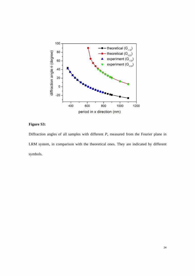
Figure S3:
Diffraction angles of all samples with different Px measured from the Fourier plane in
LRM system, in comparison with the theoretical ones. They are indicated by different
symbols.