platon cavity drain membrane - corden-bssp.co.uk · platon cavity membrane can be applied to almost...
TRANSCRIPT
Platon Cavity Drain MembraneINSTALLATION MANUAL
www.tritonsystems.co.uk

0595 09/11

2
Contents Page
Isola and Triton – history and background 3
System Platon – an introduction 4
1. General Guidance Notes on Specification and Installation 5
2. Membrane Installation (internal basement application – Multi, P5, P20) 8
3. Membrane Installation (internal basement application – Plasterbase) 13
4. Membrane Installation (external basement application Double Drain) 15
5. Triton Sump and Pump Installation 16
6. Triton Battery Back-up Pump Installation 17
7. Triton Aqua Channel Installation 18
8. Photographic illustrations 21
9. Sumps and Pumps – Guidance Notes 35
10. Free Lime – Guidance Notes 37
11. Pump Service Schedule 41
12. Specialist Service Companies 43
13. Pre and Post Installation Check List 44
14. Pipe Service Seal Detail 46
15. Product Specifications 48
16. Case Study – new build 69
17. Case Study – existing basement 71
18. Technical Drawing Details 73
3
Isola Platon MembraneTriton Systems
Background/History
Isola is the original inventor of studded membrane and was founded in 1940. The Isola Group has since grown to become one of the world leaders in the field of waterproofing membranes for the construction industry. Isola has also produced many millions of square metres of membrane products worldwide and through their research and development, continues to be at the cutting edge of innovation and technology in this field.
Triton Systems has been historically linked with Isola Platon since 1995 and in 1998 took over the U.K and Ireland operations to become the sole distributor and promoter of Isola Platon membranes and components.
Platon membranes, together with Triton’s own extensive range of water proofing and damp proofing products and water drainage systems give the specifier and installation contractor the complete basement and above ground waterproofing system that is unique within our construction industry.
4
Introduction
Isola Platon Cavity Drain Membranes
Platon Cavity Drain membranes “System Platon” are made of high-density studded polyethylene sheets (HDPE) and Polypropolene (PP), which are impervious to water and are vapour proof. When placed against structures the studs form permanent cavities between the structure and the internal shell. They can be used internally or externally to drain and control water and damp ingress.
“System Platon” is not a tanking system. The term “tanking” originates from the industrial process of lining structures with a waterproof material, which were applied either externally (on the positive side) or internally (on the negative side). Tanking materials such as multi-coat renders, cementitious waterproofing slurries, asphalts and liquid applied bitumen coatings, rely on either a mechanical or chemical bond directly on to the substrate and work by holding water back. The majority of these are vapour permeable.
Walls in the majority of circumstances are not engineered to withstand the bending stresses applied when a negative pressure barrier tanking system is used to hold back water pressure. Brick is very strong in compression but weak in tension.
Traditionally in the United Kingdom cementitious tanking systems are applied to below ground structures, but if the structure is subjected to hydrostatic water pressure, the resulting bending stresses are often far too great for the barrier system to cope with and therefore de-bonding or cracking, resulting in failure, will occur. The installation of Platon membrane doesn’t change the status quo and therefore Platon Cavity membranes are ideally the most suitable and economical method of providing an effective and long lasting waterproofing system that is also sympathetic towards building structures. For those seeking maximum assurance ‘System Platon’ is considered to be the most trouble free.
5
1.0 IMPORTANT NOTEProperties and structures vary in design and form of construction. Any specification is therefore unique to individual properties and to any special or particular circumstances encountered that may relate to the structure. The guidance notes set out below have been put together as a ‘guide only’ in order to help the specifier and membrane installer. Therefore the information given in this text and that which is provided in any product data sheet issued by Triton Systems, is made without prior guarantee, as conditions of use and labour involved are beyond our control.
1.1 Site Survey and Design Consideration
1.11 Membrane Suitability
Platon cavity membrane can be applied to almost all sound building structures below ground, which are affected by dampness or water ingress. However, they are not recommended for installation in the following situations.
• Where the cavity membrane system cannot be drained, otherwise the system will fail. (See drainage facilities and guidance notes)
• Fixed onto internal flat soffits unless the soffit has an existing fall or a fall can be formed at the design stage (in the case of new build construction) or created using sand & cement renders, otherwise water would pond behind the membrane and build up like a balloon. The weight of water would inevitably burst the membrane seals, which are not designed to hold water under pressure. An alternative for flat sofffits is shown in drawing no. IP024.1.
• Under or on top of concrete/stone staircase treads and risers, because of the many convoluting junctions and angle details. In such circumstances, we recommend they be treated independently using an epoxy vapour barrier.
1.12 Ingressing Water
Platon cavity membranes are capable of dealing with (quite) large volumes of water, so ingressing water will not usually require remedial action. But if the flow rate is such that it will be able to carry silts/dissolved lime with it, then this inflow should be stemmed/controlled prior to fitting the membrane. This can be achieved as follows.
• If ingressing water is localised then the application of Triton Quick Set plugging compound (TQS) will often be sufficient. (See TQS data sheet)
• If ingressing water is more general and cannot be dealt with by localised plugging, consideration should be given to applying a general coat of 3:1 render incorporating an accelerator in the mix.
When water is flowing through concrete or mortar (particularly when it is new) there is a tendency for dissolved lime to be brought into the cavity. This lime can then come out of solution and block up cavities and drains. If this is a risk, then the source of water ingress needs to be treated in the same way as silt bearing water, as described above.
NB: Regardless of conditions at the time of inspection, BS 8102 says it must be assumed hydrostatic pressure is going to occur at some time during the lifetime of the basement. This means that some form of water removal system must always be fitted with the Platon cavity membrane in below ground structures.
1.2 Drainage Types
There are two principle forms of drainage, these are natural (gravity) and mechanical (sump & pump) and can be used in conjunction with falls or drainage channels. However, when assessing the type of drainage facility to be used and because the drainage is the key to the success of the cavity membrane system, it is important to take into consideration the following points.
1.21 Natural – (combined foul chambers & integral gullies)
Where drainage with gravity is feasible within the bounds of the property or at a point of exit from the property, it is most important to establish that the ‘internal drainage’ is in good working order and to question whether the local drains are connected to public drains or a soakaway. Drains can and do block up or back up causing flooding, including escape of foul waste and pungent smells. Soakaways can also fill up during periods of heavy rain, which would lead to flooding and failure of the cavity membrane system. In situations where the Platon membrane installer finds that the only possibility of draining the cavity membrane is into a foul/soakaway system or his client so instructs, liability for the

6
waterproofing system should therefore be excluded in the event of blockage of the foul pipes or the soakaways filling up. Isola and Triton always recommend the inclusion of sump and pumps.
1.22 Mechanical – (sump & pump)
Triton Chemical Manufacturing Co Ltd produces an off-the-shelf sump and pump drainage system, ‘The Aqua Pump Range’ and ‘Aqua Pump Pro Range’ which has been specifically designed for the purpose of controlling ground water ingress. The simple to fit sump pump kit comprises a polyethylene pre-formed sump chamber with a structural lid. The submersible Aqua Pump is controlled by an automatic integral float switch and comes with a non-return valve and a high level water alarm that warns of mechanical or power failure. However, it would be prudent to install a double pump system ‘The Aqua Pump Plus Kit’ which consists of two pumps in the sump chamber. This secondary pump would provide a back up in case of mechanical failure of the principal pump. Consideration should also be given to installing a battery back-up pump in case of a power failure and is also available from Triton. (See technical data sheet).
1.23 Drainage Channel – (Triton Pre-formed peripheral conduit)
Triton also produces Aqua Channel, which is a P.V.C drainage conduit specifically designed for the control of water ingress in below ground situations. It is fitted around the perimeter of the floor at the vulnerable wall/floor junction and can be used in most waterproofing situations, and is particularly suited for use in conjunction with Isola Platon Cavity Drain Membrane systems. Water entering the building through the walls is controlled behind the Platon Membrane and diverted to the Aqua Channel at the base of the wall. The water enters the Aqua Channel through pre-drilled drainage holes and must then be diverted to a suitable drainage point, either natural or a sump and mechanical pump. Jetting eyes (cleaning ports) can also be incorporated into the Aqua Channel.
1.24 Falls – (Floors)
It is essential that there are no undulating surfaces or depressions in the floor. In new build or whenever floors are being replaced, the floor slabs can be designed and constructed to falls 2º or 3º towards the water collection facility i.e. sump chamber. Where an existing solid floor is to be retained a sand/cement screed can be laid over the entire floor gently sloping towards the sump. In all cases the floor should always be tested by spraying with a hose, to ensure that all water finds its way to the water collection point before laying the cavity membrane.
NOTE: Wherever possible (head height permitting) we recommend that Platon P20 be used on floors. This is because the P20 membrane has a far greater drainage capacity and significantly reduces the risk of hydrostatic pressure building up within the cavity.
1.3 Undermining Structures
1.31 Sump Chambers
Consideration must be given to the implications of fitting sumps in the ground, e.g. where unstable elements are present, such as chalk or sand. The installation of a perforated sump chamber could cause washing away and potential undermining. Therefore, in such cases, only sealed sumps should be installed and structurally held in place by concrete etc, with the water collection limited to that entering from the drainage channels. The final decision on the sump type in cases where ground conditions are unknown should be delayed until excavation is undertaken.
IMPORTANT NOTE: If there is any concern as to whether there is a risk of de-watering the ground to a condition whereby the structure as a whole could or may be undermined, then advice should be sought from a chartered engineer.
(see also sump installation guidance notes in the appendix).
7
1.32 Drainage Channel
If the Triton Aqua Channel cannot be formed/inserted into the floor at the wall/floor junction, because there are in-situ reinforcing bars in the slab. Then either a fall must be created in the floor (as previously described under the heading falls) or a series of small surface channels (cut into the floor like chevrons) must be formed with a fall towards the direction of the sump/water collection chamber.
1.33 Existing Plasters
Plaster that may be affected by being closed in behind the Platon cavity membrane, such as gypsum or lightweight plaster, or where the existing plaster is loose or de-bonding, should be removed from walls/soffits prior to membrane application. Only where dense and well adhered sand and cement renders are present and where removal may cause unwanted structural damage to substrates can they be left in place.
1.4 Substrate Preparation
One of the benefits of using cavity drain membrane is that in general, very little preparation to the substrates is required and although the cavity membrane is flexible and does not need a perfect surface for application, the following points need to be considered.
• Unsound materials on the surface like renders or plasters need to be removed. (See also Existing Plasters above.) Any organic materials such as wallpaper, timber skirtings, fixing grounds etc need to be removed.
• A specialist timber treatment contractor should investigate any fungal decay/infestations in timbers. Also timber that is in contact with damp masonry should be removed or physically isolated.
• Excessively uneven wall and floor surfaces should be dubbed out/levelled especially if timber battens are to be fixed to support dry lining board. Where a wooden floor finish is required such as T&G flooring grade chipboard, it must also be borne in mind that the membrane will follow the contours of the floor. Therefore to achieve a flat surface, any depressions or undulations must be ironed out to avoid undue movement in the floor finishes.
• Substrates must be free of sharp protruding objects and debris etc that can damage the membrane. We would also recommend that where mould, mosses, lichens and algae has affected substrates, a surface sterilisation with Triton Trisol 23 should be used.
• Loose, friable or defective masonry should be repaired to ensure a solid fixing.
See additional notes on preparation and installation checks further on in this manual.
8
2.0 MEMBRANE INSTALLATION – (internal applications in below ground structures)
2.1 Internal Basement Structures
Set out below is a generic method of installation, which can be used to apply Platon Multi, P5, and P20 cavity drain membranes continuously between wall and floor. NB it is assumed by this stage, that the site and design considerations mentioned earlier in this document, have been assessed and the type of drainage facility chosen has been tested. The installation of Platon Plasterbase and Double Drain are covered under a separate heading further in this document.
2.2 Walls and Floors
2.21 Wall application using Multi or P5/P8
The installation of Platon Multi and P5 membranes can be fixed to walls either vertically or horizontally, but when choosing the method of application, consideration should be given to the height of walls in relation to the size of the roll of membrane. There are fewer joints in horizontal applications but it can be awkward and difficult to manoeuvre the weight of a full roll of membrane. Particularly in situations where the membrane has to be taken in and out of numerous recesses, also around convoluting junctions or were walls are not square. Vertical application may have more joints, but this method is more manageable and much easier to fix.
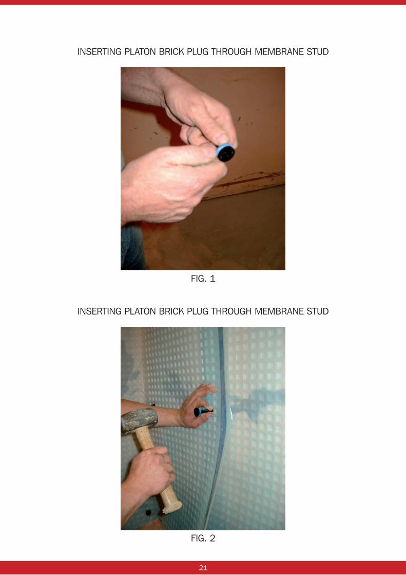
Platon Multi or P5/P8 cavity membrane is fixed to walls with the Platon Brick Plug. The brick plugs should be prepared for use before fixing by wrapping Platon Sealing Rope around the neck of plug just under the head. This will form a seal with the membrane when the plug is driven home into the substrate. (See fig 1)
If the ceiling height is constant, measure and cut drops of the membrane to completely cover the wall areas to be treated. Place the membrane against the wall as level as possible by eye sight and in the top right or left hand corner (depending on which way around the room the membrane is being taken) drill a hole through the centre of the membrane stud using a 10mm drill bit. Insert the brick plug and hammer home the plug till it finishes flush with the membrane. (See fig 2)
Using a spirit level, level out the membrane and then drill and fix another brick plug in the same manner approximately 1.5m along the top of the sheet and along the same line of stud as the first fixing. Offer up the next length of membrane and position the flange over the studs of the first sheet and fix with two Brick Plugs at high level as previously described. Continue on in this manner, ensuring the membrane stays as level as possible until all the walls are covered. These independent membrane drops will relax after a while and hang flatter to the wall. The drops are now ready for the next step.
Thoroughly clean the flange and the studs where the seal is to be made, (the best cleaning material is a standard kitchen roll). Any dust or dirt will compromise the integrity of the sealed joint. If the membrane is covered in plaster or brick dust, wash off with clean fresh water only and allow to dry. DO NOT use soap or detergents, as these will leave traces on the membrane, which may affect the seal at a later date or make sealing more difficult.
The separate membrane drops should now be sealed together using Platon Sealing Tape. Apply the tape to the stud area below, which the flange will cover and press home onto the area between the studs. Flick over the flange section to cover the tape line, and check for uniformity of cover on tape line. Remove the tape backing paper, starting from the middle section of the wall drop, forming two backing paper tags, one going up and the other down. On the exposed section of tape apply hand pressure only to the flange to form an initial seal. Carry on to form the seal from the centre section of membrane working up to the top, then go back to the centre and repeat the operation going downwards. Sealing in this manner will prevent any buckling between the membrane or stress concentration at the joint. In very cold or humid conditions a hot air gun can be used to obtain a good sealed joint. (See fig 3, 4, 5, 6)
Now that the membrane is sealed to form one continuous sheet, Platon Brick Plugs can now be fixed through the membrane in position to accommodate the chosen dry lining system.
NOTE: Although a 10mm drill bit is the correct size to use, in very soft brickwork this can result in loose fixing. In these circumstances, it is useful to have on hand drill sizes down to 8mm and experiment with different sizes for the best results.

9
2.22 Floor application using Platon P20
Once the membrane has been fitted to the walls and before the dry lining system is installed, the floor membrane needs to be laid. As mentioned earlier in this document Platon P20 membrane is recommended on floors unless there is a head height restriction, in which case Platon Multi or P5 can be used, but the installation of Platon Multi and P5 on floors differs slightly from that of P20 and is explained below.
Begin at one side of the room and unroll the Platon P20 floor membrane against the wall membrane with the studs facing down onto the floor and cut the membrane to the desired length or width of the floor, just like laying a carpet. Repeat this exercise till all the lengths/widths required to cover the floor area have been cut allowing for a two-stud membrane overlap. (See fig 7)
The individual sheets of membrane that have now been cut, are joined together with Platon Sealing Rope. The sealing rope is positioned between the two stud formations along the edge of the membrane to be overlapped and remove the release paper. Lift the next sheet of P20 membrane over the two interlocking studs and press the overlapping membrane down onto the sealing rope. (See fig 7, 8, 9, 10)
Foot pressure can be applied by sliding the sole of the foot over the membrane joint, to ensure that the membranes are fully bonded. The next stage of the operation is to link the P20 floor membrane to the wall membrane, which can be achieved, using Platon Wall/Floor Junction or Corner Strip. Using Platon Wall/Floor Junction, work out how many linear metres there are around the walls, the Platon Wall/Floor junction is produced in manageable 2LM lengths with a crease formed in the centre. Fold the material in half down the centre crease and then apply Platon Sealing Tape along the edges of the wall/floor junction material and leave the backing paper on. (See fig 11)
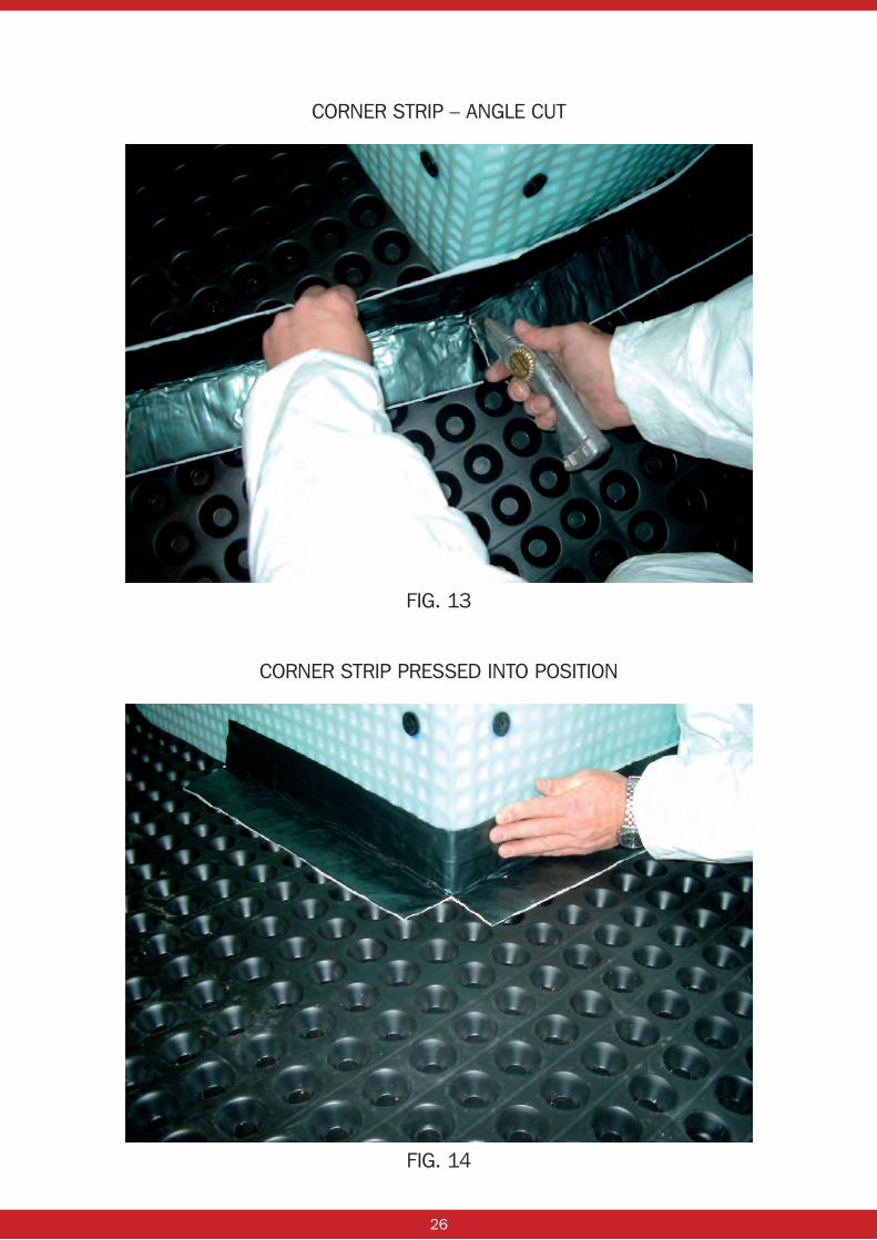
If the one-sided adhesive corner strip is chosen to link the floor and wall membrane, the corner strip is folded in half along the length of the piece to be used and positioned with the crease into the angle as described for the wall/floor junction. Once correctly aligned, carefully pull off the backing paper and press firmly out with the palm of the hand onto the floor and wall membranes. Internal and external angles can be formed in the same manor as the Platon Wall/Floor Junction, but because it is a one-sided self-adhesive material and will stick to itself, no additional sealing tape is required. (See fig 12, 13, 14, 15, 16, 17)
2.23 Floor application using Platon Multi or P5/P8
As with the P20, begin at one side of the room and unroll the floor membrane against the wall membrane with the studs facing down onto the floor. Allow for the membrane flange overlap, cut the membrane to the desired length or width of the floor. Repeat this exercise until all the lengths/widths required to cover the floor area have been cut.
Roll out the next length/sheet of membrane and position the flange over the studs of the first sheet laid and thoroughly clean the flange and the studs where the seal is to be made as previously described for wall application. Apply Platon Sealing Tape to the stud area below which the flange will cover and press home onto the area between the studs.
Flick over the flange section to cover the tape line, and check for uniformity of cover on tape line. Remove the tape backing paper, starting from the middle section of the membrane sheet, and peel off backing paper in opposite directions along the flange. On the exposed section of tape apply hand pressure only to the flange to form an initial seal. Carry on forming the seal working away from the centre of the membrane. Foot pressure can be applied by sliding the sole of the foot over the membrane joint, to ensure that the membranes are fully bonded. Sealing in this manner will prevent any buckling between the membrane or stress concentration at the joint. In very cold or humid conditions a hot air gun can be used to obtain a good sealed joint.
The next stage of the operation is to link the floor membrane to the wall membrane, which can be achieved, using Platon Wall/Floor Junction or Corner strip. Using Platon Wall/Floor Junction, work out how many linear metres there are around the walls, the Platon Wall/Floor Junction is produced in manageable 2Lm lengths with a crease formed in the centre. Fold the material in half down the centre crease and then apply Platon Sealing Tape along the edges of the wall/floor junction material and leave the backing paper on.
Ensure that the floor and wall membrane is clean and free from debris, dust and moisture and then position the Platon Wall/Floor Junction with the crease into the angle. Working from the centre, carefully peel back the backing paper in each direction and use hand pressure along the taped edges to form a seal. To form internal and external angles using Platon Wall/Floor Junction, the wall/floor Junction is cut to the centre line and bent either inwards or outwards depending on the angle. The edges are then sealed with tape to the membrane in the same manner as described above.
10
If the one-sided adhesive corner strip is chosen to link the floor and wall membrane, the corner strip is folded in half along the length of the piece to be used and positioned with the crease into the angle as described for the wall/floor junction. Once correctly aligned, carefully pull off the backing paper and press firmly out with the palm of the hand onto the floor and wall membranes. Internal and external angles can be formed in the same manner as the Platon Wall/Floor Junction but because it is a one-sided self-adhesive material and will stick to itself, no additional sealing tape is required. (See fig 12, 13, 14, 15, 16, 17)
2.24 Flat Soffit Application using Platon Multi or P5
As previously mentioned earlier in this document, Platon cavity drain membrane should not be fixed to the under side of a flat soffit unless a fall exists or a fall can be created in the soffit itself. The soffit should first be measured to establish the desired lengths or widths of membrane required to cover the area and then a further 200mm of membrane should be added to the measurements, to allow for the membrane to be lapped down all the peripheral walls.
Apply sealing rope to the Platon Brick Plugs as previously described. Then around the perimeter edges of the membrane, fold the membrane inward 200mm to form a positive creased and create a down lap. Offer the membrane up to the soffit and position the down lap creases into the junction between the soffit and wall.
Drill and fix enough Platon Brick Plugs through the membrane and into the soffit to hold the membrane in place with the studs against the soffit. NB: Wherever the soffit membrane meets the wall, a 200mm down lap must be allowed and formed as above.
Offer the next length/sheet of membrane up to the soffit and position the flange over the studs of the first sheet, fix and secure the membrane as described above. Repeat this operation until all the membrane sheets are held in place. Thoroughly clean the flange and the studs where the seal is to be made as previously described for wall application. Apply Platon Sealing Tape to the stud area, which the flange will cover and press home onto the area between the studs. The membrane should now be sealed to form one continuous sheet, Platon Brick Plugs can now be fixed through the membrane, in positions to accommodate the chosen dry lining system.
NOTE: It is important to ensure that the membrane is taut against the soffit and doesn’t sag, otherwise water ponding will occur and the membrane/seals could fail.
Internal and external corners are formed in exactly the same way as that which has been previously described in ‘Floor application using Multi or P5 with membrane upstand’ except in this case, they will be formed in reverse and be upside down.
NOTE: An alternative method for dealing with flat soffits using a combination of Platon membrane to walls and Triton TT55 slurry to soffit can be see in technical drawing section, drawing no. IP025.1.
2.25 Service Entry Seals
Where there are services such as pipes, ducting or steel stanchion that protrude through walls or floors, the membrane should be carefully cut and trimmed around the obstacle and sealed using a combination of Platon Sealing Rope or flexible mastic and corner strip material. Cloaks can also be formed using the wall/floor junction. (See fig 18 and drawing IP027.1)
2.26 Doors and Windows
Door and window frames and timber surrounds should always be removed to enable Platon membrane to be extended around or into door and window reveals to maintain the continuity of the waterproofing system and to also provide a physical barrier between the frames and damp masonry. In situations where the Platon membrane would restrict or limit the profile of replaced frames, then Platon Wall/Floor Junction or Platon DPC Plain can be used to line and protect the reveals instead. See drawing no. IP026.1.
11
2.27 Ventilation – Part F of Building Regs
There is no requirement to ventilate the membrane cavity in a fully sealed system such as in under pavement vault application. In a semi sealed system, the cavity between membrane and substrate can be vented into the room space with passive vents or if this is not possible, it can be vented through the external wall using a 150 x 225 air brick inserted every 1.5m to 2.0m along the wall. It is important that the cavity between the membrane and internal finish i.e. dry lining is not vented so as to avoid possible interstitial condensation. However, consideration should be given to the risk of condensation forming within the room itself and the introduction of a humidistat controlled extract fan should therefore be recommended. Refer to BS8102 (2009) Table 2 for further reference. Part F of Building Regulations concerning ventilation in basements. Please refer to Triton’s Anti Condensation Products brochure for suitable products such as Positive Pressure units.
2.28 Wall Finishing
If timber battens are to be used, the traditional method is to fix a vertical batten 25mm x 50mm. The brick plugs in this instance should be fixed at 400mm centres horizontally and 600mm centres vertically. The timber batten is screw fixed into to the self-tapping hole, which has been formed in the Platon brick plug using a size (10) x 2" screw. NB: We would however, recommend that foil back plasterboard be used to prevent interstitial condensation forming in the cavity.
For a metal fast track dry lining system such as Gypliner or Lafarge, the brick plugs should be fixed at 600mm centres horizontally and 800mm centres vertically. If an independent timber or metal frame system is to be used, the wall membrane can be ‘curtain hung’. The membrane is simply dressed down the walls just like hanging a curtain or sheet. This method of installation requires less fixings.
NOTE: We would however, recommend that foil back plasterboard be used to prevent interstitial condensation forming in the cavity.
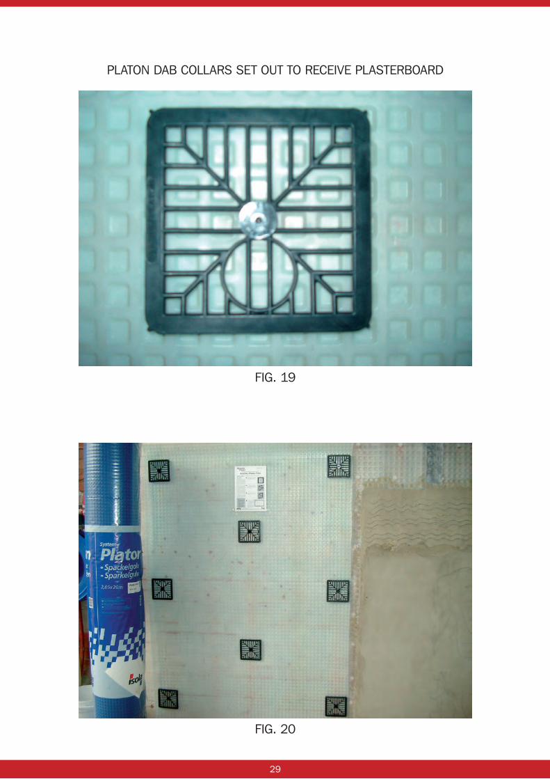
On fair faced walls the Platon Plaster Dab Collar System can be used. The collars, which incorporate a built in fixing plug going through the centre of the collar, are sealed as before with rope on the collar face rather than under the fixing plug head. The fixing collars are set out according to the width of the plasterboard to be used. (See fig 20, 21)
Generally, eight collars per sheet of plasterboard are required. The dab collars on the edge will also take the next sheet of plasterboard. When the collars have been fixed, insert 25mm size 10 screws into the pre-formed hole of the brick plug and adjust the screws in or out as the case may be to a constant final fix level for the final board finish.
Mix the plasterboard adhesive in accordance with manufacturer’s instructions, and apply dabs of adhesive to the collars, ensuring that it goes through the collar gridding, and generously covers the levelling screw heads. Place some batten off cuts on the ground under the bottom of the plasterboard to support it until the adhesive has set. Stand the plasterboard on these support battens; position and press home onto the adhesive until the levelling screws stop any further movement.
The plasterboard must now be left for the adhesive to set, after which the support battens can be removed.
NB: Unfortunately, this form of dry lining system cannot be used with foil back plasterboard because the adhesive won’t adhere to the foil back material.
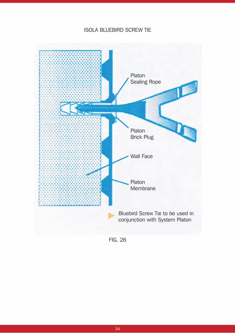
If an independent brick/block wall needs to be built in front of the Platon wall membrane and requires lateral restraints, then Isola Bluebird Fixings can be used or a similar suitable product. Isola Bluebird Fixings are screwed into the self-tapping hole of the Platon Brick Plug and anchored into the mortar bed joint as the wall is built. (See fig 26) Independent free standing walls can also be built directly off Platon floor membranes, but we would recommend advice is sought from our technical department before proceeding.
12
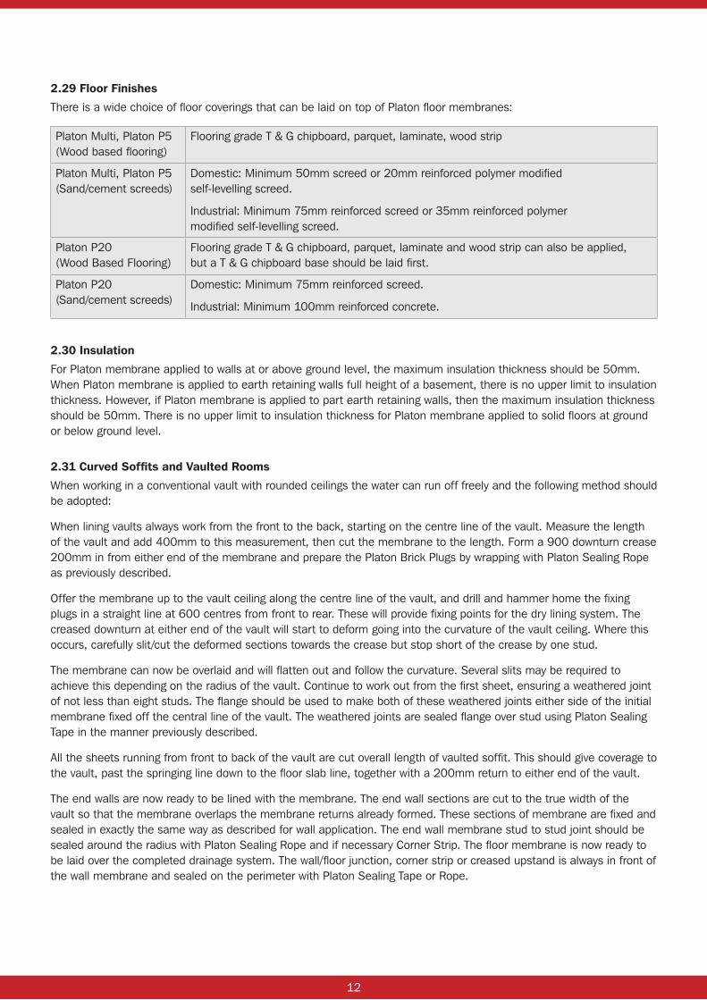
2.29 Floor Finishes
There is a wide choice of floor coverings that can be laid on top of Platon floor membranes:
Platon Multi, Platon P5 (Wood based flooring)
Flooring grade T & G chipboard, parquet, laminate, wood strip
Platon Multi, Platon P5 (Sand/cement screeds)
Domestic: Minimum 50mm screed or 20mm reinforced polymer modified self-levelling screed.
Industrial: Minimum 75mm reinforced screed or 35mm reinforced polymer modified self-levelling screed.
Platon P20 (Wood Based Flooring)
Flooring grade T & G chipboard, parquet, laminate and wood strip can also be applied, but a T & G chipboard base should be laid first.
Platon P20 (Sand/cement screeds)
Domestic: Minimum 75mm reinforced screed.
Industrial: Minimum 100mm reinforced concrete.
2.30 Insulation
For Platon membrane applied to walls at or above ground level, the maximum insulation thickness should be 50mm. When Platon membrane is applied to earth retaining walls full height of a basement, there is no upper limit to insulation thickness. However, if Platon membrane is applied to part earth retaining walls, then the maximum insulation thickness should be 50mm. There is no upper limit to insulation thickness for Platon membrane applied to solid floors at ground or below ground level.
2.31 Curved Soffits and Vaulted Rooms
When working in a conventional vault with rounded ceilings the water can run off freely and the following method should be adopted:
When lining vaults always work from the front to the back, starting on the centre line of the vault. Measure the length of the vault and add 400mm to this measurement, then cut the membrane to the length. Form a 900 downturn crease 200mm in from either end of the membrane and prepare the Platon Brick Plugs by wrapping with Platon Sealing Rope as previously described.
Offer the membrane up to the vault ceiling along the centre line of the vault, and drill and hammer home the fixing plugs in a straight line at 600 centres from front to rear. These will provide fixing points for the dry lining system. The creased downturn at either end of the vault will start to deform going into the curvature of the vault ceiling. Where this occurs, carefully slit/cut the deformed sections towards the crease but stop short of the crease by one stud.
The membrane can now be overlaid and will flatten out and follow the curvature. Several slits may be required to achieve this depending on the radius of the vault. Continue to work out from the first sheet, ensuring a weathered joint of not less than eight studs. The flange should be used to make both of these weathered joints either side of the initial membrane fixed off the central line of the vault. The weathered joints are sealed flange over stud using Platon Sealing Tape in the manner previously described.
All the sheets running from front to back of the vault are cut overall length of vaulted soffit. This should give coverage to the vault, past the springing line down to the floor slab line, together with a 200mm return to either end of the vault.
The end walls are now ready to be lined with the membrane. The end wall sections are cut to the true width of the vault so that the membrane overlaps the membrane returns already formed. These sections of membrane are fixed and sealed in exactly the same way as described for wall application. The end wall membrane stud to stud joint should be sealed around the radius with Platon Sealing Rope and if necessary Corner Strip. The floor membrane is now ready to be laid over the completed drainage system. The wall/floor junction, corner strip or creased upstand is always in front of the wall membrane and sealed on the perimeter with Platon Sealing Tape or Rope.
13
3.0 PLATON PLASTER BASE MEMBRANE AND PLATON MESH APPLICATION – (internal applications in below ground structures)
Platon Plaster Base can be applied onto existing solid wall finishes. All surfaces must be of a sound, firm nature and any loose areas should be removed prior to application. Any voids or hollow areas should be filled or dubbed out prior to application. Where necessary a fungicide wash should be applied to the wall surface. Platon Plaster Base is for internal use only on walls and curved soffits and is compatible with other Platon membranes. Platon Plaster Base is not recommended for external application and should not be used on floors.
Platon Plaster Base membrane is fixed to walls with the Platon Plaster Plug. The Plaster Plugs should be prepared for use before fixing by wrapping Platon Sealing Rope around the neck of plug just under the head. This will form a seal with the membrane when the plug is driven home into the substrate.
If the ceiling height is constant, measure and cut drops of the membrane to completely cover the wall areas to be treated. Place the membrane against the wall as level as possible by eyesight. In the top right or left hand corner (depending on which way around the room the membrane is being taken) drill a hole, 3 studs in from the edge through the centre spacing between 4 studs, not through the stud itself. Use an 8mm drill bit and insert the Plaster Plug and hammer home until it finishes flush with the membrane. (See fig 22)
Using a spirit level, level out the membrane and pull taut, then drill and fix another Plaster Plug in the same manner at the other top edge of the sheet. Offer up the next length of membrane and position the membrane so that this sheet overlaps by a minimum of (2) studs over the first sheet and fix with two Plaster Plugs at high level as previously described. Continue on in this manner, ensuring the membrane stays as level as possible until all the walls are covered. These independent membrane drops will relax after a while and hang flatter to the wall. The drops are now ready for the next step.
Down the overlap joint, fix Platon Plaster Plugs through the studs as close as possible to the edge of the overlapping membrane. Fixings should be made at 150mm centres along this joint. Continue fixing the Plaster Plugs in a diamond pattern through the centre spacing between the 4 studs until sufficient fixings have been installed, ‘minimum 13/m²’.
The membrane must fit tight against the structure with no voids or hollow areas left between the wall and the membrane, as this could cause bonding problems between the membrane and the plaster/render. Care should also be taken at corners to ensure the membrane is fitted tightly into the corner so to avoid snagging or tearing with a trowel.
Once all fixings are in place, clean the membrane surface thoroughly along the overlap joint and ensure it is dry and free from dust. Apply Platon Fleece-back Overtape along the joint with equal overlaps onto each sheet of membrane and press firmly into place. Platon floor membrane can now be laid over the completed drainage system. Wall/Floor Junction, Corner Strip or a creased upstand is always placed in front of the Plaster Base membrane and sealed on the perimeter with Platon Sealing Tape or Rope. If the plaster finish is required to extend down to the finished floor and therefore over the wall/floor junction or corner strip or upstand, Platon Fleece-back Overtape will need to be applied to provide a key for plastering.
3.1 Finishes
Most common lightweight and renovating plasters (Triton Renovating Plaster) or sand/cement renders can be applied to Platon Plaster Base. (The use of British Gypsum Hardwall or Tuff Coat is not recommended).
When using sand/cement render, mixes of 1 part cement to 6 parts washed plastering sand, incorporating either Triton SBR or hydrated lime should be used. NB Grade ‘M’; medium sharp sand should be used. Do not use soft or building sand.
All render/plasters should be applied in a minimum of two coats, allowing the first coat of 7mm – 10mm to be trowelled firmly into the membrane studs and then scratched to provide a key for subsequent coats to be applied. The first scratch coat should be left to cure and harden. Ideally this should be 7 – 10 days depending on site and atmospheric conditions. The minimum plaster thickness should be 15mm and the maximum thickness (sand/cement 30mm) (lightweight plasters 40mm). Plasterboard can also be dot and dabbed onto the plasterbase as a fast track system, using board adhesive.

14
3.2 Fixing through Plaster Base after Plastering or Rendering
On occasions where a fixing is required through the membrane, any one of the three fixing methods set out below can be used to achieve this.
3.21 By using a Platon brick plug with Platon rope seal.
First mark out on the plaster surface where the fixing is required and then place the head of the brick plug over the mark and draw a pencil line around the circumference of the head. Drill a 10mm hole through the centre and carefully scrape/scratch out the plaster within the pencil line back to expose the membrane. Blow out the debris, insert the brick plug and hammer the plug home so that the head of the plug sits flush with the membrane surface.
3.22 By using a rawl plug.
Simply drill a hole through the plaster and membrane and clean debris from the hole. Fill the hole with Triton epoxy resin, allowing the resin to ooze out slightly onto the plaster surface and insert the rawl plug and allow to harden.
3.23 By using contact adhesive and timber batten.
As before, mark out where fixing is required and remove any setting coat plaster. Apply triton epoxy resin to the surface area and to the timber batten and press the batten into position. Some temporary support may be required until the timber has fully bonded.

15
4.0 PLATON DOUBLE DRAIN MEMBRANE APPLICATION – (For external applications only)
The material can be fitted either vertically or horizontally and therefore would depend on the size of the job as to which option is chosen. It is considered far more economical to fit the product horizontally.
4.1 Wall Preparation
The wall surfaces must be clean and free from cavities and protruding sharp objects. Where protruding ribs or foundation toes occur, a concrete/sand and cement filler piece should be cast/formed to prevent water gathering or laying against the foundation slab.
Apply a bitumen primary membrane to the walls and foundation toe, with a minimum of two coats and allowing 24 hours drying time between each coat.
4.2 Membrane Installation
Starting at the base of the walls, roll out the Platon double drain horizontally against the wall with the filter fabric outwards and fix the Fixing Cramps along the top edge only at 250mm centres. The membrane is hung down the walls like a curtain.
NOTE: If a foundation toe protrudes out from the wall, then the membrane should be extended over the horizontal section of the toe and down the vertical edge.
Continue fitting the membrane horizontally as described above around all walls. Where the next roll/sheet of membrane is to be joined at the vertical edge, carefully peel back the filter fabric from the membrane to be overlapped by approximately 120mm. Platon Sealing Rope is then laid in a vertical line within the channel between the first and second stud and the overlapping section of membrane is then pressed stud to stud to form a seal down the vertical joint.
Once the bottom run of membrane has been fitted horizontally around the walls, the next roll of membrane is also run horizontally in the same manner as above. However, the top membrane overlaps the bottom membrane at the horizontal joint by 120mm. Again the filter fabric is carefully peeled back from the bottom membrane at the joining edge to allow a stud to stud overlap. No sealing rope at this horizontal joint is necessary, but fixing cramps are required at 250mm centres along the joint.
The membrane should be terminated 150mm above external ground level and at this point the Platon Top Edge Mould is fixed using masonry nails. At the base of the wall a graded drainage material should be laid incorporating a geo-textile perforated land drainage pipe. The size of this pipe will need to be determined by the project engineer. Once the drainage pipe is in place, it should be water tested before being concealed with graded backfill/drainage material. We recommend that the external ground be finished with a 1 in 50 gradient away from the walls.
Finally, compaction of back-fill should be conducted with care to avoid damaging the membrane, and direct tipping from lorries should be avoided.
16
5.0 TRITON SUMP AND PUMP INSTALLATION – AQUA PUMP RANGE
5.1 Triton Aqua Pump (Single Sump & Pump kit with Alarm)
The site conditions or situation being encountered may well determine the positioning of the Triton Aqua Pump System. However, ideally it should be sighted at the lowest point of the room and or closest to the nearest point where water will be discharged. The most important thing is to make sure that water can get to the pumping station. Once the pump position has been established, dig a circular hole to a depth of 650mm and to a width of 650mm.
At the base of the sump basin, drill 4 holes (12mm dia) opposite to each other. Cut two lengths of reinforcing bar (660mm long) and insert through holes at base of sump basin.
Fit the high water level alarm float switch sensor into the pre-cut hole provided within the wall of the sump basin and ensure that the jaw of the switch sensor is open and hangs downwards. Bring the two cables with bullet connectors attached back into the sump basin either through one of the holes provided or by drilling a hole and leave ready to be connected to the wires of the water alarm.
NOTE: if the water discharge pipe from the pump is to be concealed below the floor, then a 1½" hole will need to be cut through the side of the basin. However, the position of this hole can only be determined once the sump basin has been offered into position, otherwise the discharge pipe can be taken through the lid of the basin.
Lay 100mm concrete in the base of the hole and insert the sump basin. Using a spirit level, adjust the top of the basin to the level of the finished floor level. Fill the sump basin two thirds with water. Then fill around sides of sump basin with concrete. NB: If Platon membrane is being installed over the floor, then the concrete will need to finish approx 100mm below top of sump basin, the top of the sump basin to be perforated and then the void above the concrete to be filled with 20mm stone. However, IF Platon membrane is not going to be installed over the floor, the concrete to be finished flush with top of sump basin. (see drawing no. IP029.1).
Insert the Aqua Pump in the base of the sump basin and connect the water discharge pipe to the flexible coupling already attached to the pump. The discharge end of the pipe can be taken through a wall and extended to a gully outlet at ground/street level. Alternatively, the discharge pipe can be connected straight into a soil pipe using a ‘boss’ connection. Where a double pump installation is being used (Aqua Pump Plus), each pump must be wired into an independent fused spur outlet. One of the Aqua Pumps (the secondary pump) in the double pump kit will have been fitted with 25mm long spacers at the base of the pump so that this pump is raised off the bottom of the sump basin.
Connect the wires from the float switch sensor to the wires of the water alarm using the bullet connectors provided. Then connect the pump/s power cable into a fused spur outlet and test the pump and alarm for working order. (See fig 24 showing completed Aqua Pump installation.)
NOTE: If there is any concern as to whether there is a risk of de-watering the ground to a condition whereby the structure as a whole could or may be undermined, then advice should be sought from a chartered engineer.
5.2 Maintenance
It is recommended that the Triton Aqua Pump is maintained/serviced every six months. This should be carried out by the installing contractor (under a maintenance contract) or by the property owner. During this service the float switch should be checked and the pump should be operated with water from the sump chamber to ensure it is fully operational and that the sump chamber be cleaned of any sludge/silt that may have accumulated. In addition to this, the high water level battery alarm box and alarm sensor should also checked for working order. * See pump service schedule in appendix for required minimum service and maintenance.
5.3 Important Note:
The Triton Aqua Pump & Battery Back-up Pump systems must only be used for pumping ground water. The pump/s should not be used to pump grey water from; sinks/washing machines/dishwashers/condensing boilers or effluent. Triton Chemical Manufacturing Ltd will not accept responsibility or liability for pump failure or damage caused due to the misuse of the pumping system.
17
6.0 TRITON BATTERY BACK-UP PUMP SYSTEM Position the Battery Back-up Pump kit in the desired location.
NOTE: The flexible suction hose should not be extended greater than 1.8m from the base of the sump chamber.
Run the flexible suction hose from the sump chamber (allowing approximately 50mm of hose off the base of the sump) and secure the hose to the side of the chamber with the clips provided.
Connect the outer end of the flexible suction hose to the pump inlet with the jubilee clip provided and secure tight.
The battery pump’s float switch is secured within the chamber to the vertical discharge pipe that extends from the primary pump, with a nut and bolt-clamping bracket. This will normally be pre-fixed in place around a section of vertical discharge pipe when delivered with a primary pump i.e. the Aqua Pump Kit or Aqua Pump Plus Kit. If it is found that the float switch and clamping bracket are not pre-fixed around a section of vertical discharge pipe, then the float switch and clamping bracket must be fitted, positioned and adjusted so as to ensure there is free movement of the float switch in the sump chamber.
Connect the battery pump float switch cable/wire to the connector block located inside the back-up pump housing.
Solvent weld the discharge pipe to the pump outlet and connect this water discharge pipe to a suitable drainage point: drainage gulley, stack pipe using a ‘Boss Connector’ or T-Connector.
Connect each battery cable to the correct battery terminal and tighten the connector bolts and then plug-in the battery charger to the power supply. The battery will begin to charge.
The battery charge state is indicated by the L.E.D display on the charger. Once the battery is charged, fill the sump chamber with water and test the Battery Back-up System several times to ensure it is fully operational.
6.1 Maintenance
It is recommended that the Triton Battery Back-up System is maintained/serviced every six months. This should be carried out by the installing contractor (under a maintenance contract) or by the property owner. During this service the principle pump/s should be temporarily isolated then the battery back-up pump float switch should be tested and checked it is working properly. The sump chamber should be filled with water and the Battery Back-up Pump should then be run so that the water is discharged from the sump chamber, which ensures that the pump is fully operational.
The distilled water levels within the battery should be checked and topped up as necessary to ensure the cells do not run dry. In addition to this, the high water level battery alarm box and alarm sensor should also be checked for working order.
6.2 For new Aqua Pump Range – See separate Complete Installation Guidelines at www.tritonsystems.co.uk
Please refer to pages 33 – 42 for further information on:
• Pump Maintenance • Sump Installation • Pump Types and Capacities • Pre & Post Installation Checklist

18
7.0 TRITON AQUA CHANNEL
Installation
7.1 Form a trough 130mm deep x 130mm wide in the floor at the wall/floor junction. (See also fig 25)
7.2 Apply the waterproof coating or Platon Cavity Drain Membrane to the wall and finish 100mm minimum below existing floor level. (See also fig 26)
7.3 Lay a shallow bed of 20mm stone into the trough. Place the Triton Aqua Channel onto the stone with the upstand to the top and flat against the waterproofing/cavity drain membrane to the wall. Lengths of Aqua Channel are butt jointed on straight runs and can be mitred in corners. Joints should be sealed with a suitable tape, Platon Over Tape or builders’ duck tape, to avoid debris from falling into the channel. (See also fig 27)
7.4 Fit the Aqua Channel outlet into the Aqua Channel at the appropriate location. The Aqua Channel outlet requires a 40mm hole in the underside of the Aqua Channel. The Aqua Channel outlet is solvent welded to the channel using the internal male coupling. A chase should be formed into the floor to accommodate the outlet pipe from the Aqua Channel to the sump or drain.
7.5 Infill the remaining gap between the Aqua Channel and the side of the trough with 20mm stone and finish flush with the flat surface of the Aqua Channel. (See also fig 28)
7.6 When installing Platon membrane over the floor, make good the remaining area with 20mm stone. Lay the membrane over the floor area and seal to the wall membrane using Platon Wall/Floor Junction or Platon Sealing Rope.
7.7 When Platon membrane is not going to be installed over the floor, make good the remaining area with approximately 50mm screed.

19
Maintenance
It is recommended that the Triton Aqua Channel be jet washed via the jetting ports, which should be incorporated in the channel system, at least once every six months. This should be carried out by the installing contractor (under a maintenance contract) or by the property owner. During this cleaning process the pump/s (if installed) should also be run with water out of the sump chamber to ensure they are fully operational and that the sump chamber be cleaned of any sludge/silt that may have accumulated. In addition to this, the high water level battery alarm box and alarm sensor should also checked for working order.
See Pump Service Schedule on page 38.
20
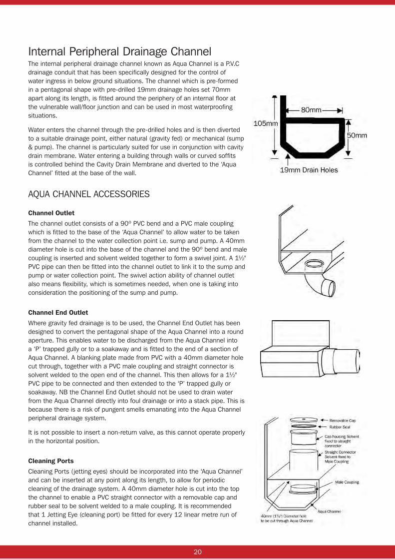
Internal Peripheral Drainage ChannelThe internal peripheral drainage channel known as Aqua Channel is a P.V.C drainage conduit that has been specifically designed for the control of water ingress in below ground situations. The channel which is pre-formed in a pentagonal shape with pre-drilled 19mm drainage holes set 70mm apart along its length, is fitted around the periphery of an internal floor at the vulnerable wall/floor junction and can be used in most waterproofing situations.
Water enters the channel through the pre-drilled holes and is then diverted to a suitable drainage point, either natural (gravity fed) or mechanical (sump & pump). The channel is particularly suited for use in conjunction with cavity drain membrane. Water entering a building through walls or curved soffits is controlled behind the Cavity Drain Membrane and diverted to the ‘Aqua Channel’ fitted at the base of the wall.
AQUA CHANNEL ACCESSORIES
Channel Outlet
The channel outlet consists of a 90º PVC bend and a PVC male coupling which is fitted to the base of the ‘Aqua Channel’ to allow water to be taken from the channel to the water collection point i.e. sump and pump. A 40mm diameter hole is cut into the base of the channel and the 90º bend and male coupling is inserted and solvent welded together to form a swivel joint. A 1½" PVC pipe can then be fitted into the channel outlet to link it to the sump and pump or water collection point. The swivel action ability of channel outlet also means flexibility, which is sometimes needed, when one is taking into consideration the positioning of the sump and pump.
Channel End Outlet
Where gravity fed drainage is to be used, the Channel End Outlet has been designed to convert the pentagonal shape of the Aqua Channel into a round aperture. This enables water to be discharged from the Aqua Channel into a ‘P’ trapped gully or to a soakaway and is fitted to the end of a section of Aqua Channel. A blanking plate made from PVC with a 40mm diameter hole cut through, together with a PVC male coupling and straight connector is solvent welded to the open end of the channel. This then allows for a 1½" PVC pipe to be connected and then extended to the ‘P’ trapped gully or soakaway. NB the Channel End Outlet should not be used to drain water from the Aqua Channel directly into foul drainage or into a stack pipe. This is because there is a risk of pungent smells emanating into the Aqua Channel peripheral drainage system.
It is not possible to insert a non-return valve, as this cannot operate properly in the horizontal position.
Cleaning Ports
Cleaning Ports (jetting eyes) should be incorporated into the ‘Aqua Channel’ and can be inserted at any point along its length, to allow for periodic cleaning of the drainage system. A 40mm diameter hole is cut into the top the channel to enable a PVC straight connector with a removable cap and rubber seal to be solvent welded to a male coupling. It is recommended that 1 Jetting Eye (cleaning port) be fitted for every 12 linear metre run of channel installed.
21
FIG. 1
FIG. 2
INSERTING PLATON BRICK PLUG THROUGH MEMBRANE STUD
INSERTING PLATON BRICK PLUG THROUGH MEMBRANE STUD

22
FIG. 3
FIG. 5
FIG. 4
FIG. 6
FLANGE TO STUD SEALING TAPE JOINT

23
FIG. 7
P20 FLOOR MEMBRANE CUT AROUND PERIMETER WALLS
POSITIONING OF SEALING ROPE BETWEEN TWO STUDS OF THE P20 MEMBRANE
FIG. 8

24
FIG. 9
FIG. 10
PRESS MEMBRANES TOGETHER TO ENSURE BOND
POSITIONING MEMBRANE STUD TO STUD OVER ROPE SEAL

25
FIG. 11
FIG. 12
CORNER STRIP WITH CREASE OFFERED INTO ANGLE
FORMING 90° ANGLE CREASE IN CORNER STRIP
26
FIG. 13
FIG. 14
CORNER STRIP PRESSED INTO POSITION
CORNER STRIP – ANGLE CUT

27
FIG. 15
FIG. 16
ANGLE PIECE TO SEAL & COMPLETE CORNER JOINT

28
FIG. 17
COMPLETED CORNER STRIP WALL/FLOOR JUNCTION DETAIL
FIG. 18
TAPE SEAL TO SERVICE PIPE DUCTS PROTRUDING THROUGH WALL STRUCTURE AND MEMBRANE
29
FIG. 19
FIG. 20
PLATON DAB COLLARS SET OUT TO RECEIVE PLASTERBOARD

30
FIG. 21
FIXING PLASTER BASE PLUG BETWEEN 4 STUDS OF THE MEMBRANE
COMPLETED AQUA PUMP INSTALLATION
FIG. 22

31
FIG. 23
130MM X 130MM GULLY CAST TO RECEIVE AQUA CHANNEL
PLATON MEMBRANES INSTALLED TO WALL
FIG. 24

32
FIG. 25
AQUA CHANNEL TO CAST GULLY

33
FIG. 26
FIG. 27
INFILLING TO AQUA CHANNEL AND GULLY WITH AGGREGATE
AQUA CHANNEL INSTALLATION INCLUDING INSPECTION PORT
34
FIG. 26
ISOLA BLUEBIRD SCREW TIE
Platon Sealing Rope
Platon Brick Plug
Platon Membrane
Bluebird Screw Tie to be used in conjunction with System Platon
Wall Face
35
Cavity Drain Membrane Systems: Sumps and Pumps: Guidance Notes.
Introduction:In most cases when installing the Isola Platon cavity drain system the actual level of water ingress or potential level of water ingress is not known. However in accordance with BS 8102 (2009) IT MUST BE ASSUMED THAT WATER WILL INGRESS AT SOME POINT IN TIME. BS 8102 (2009) states that all type ‘C’ drained protection systems need to be maintainable.
1. Pump Capacity:
If the water ingress is known then the required minimum capacity of the sump and pump system can be easily calculated. The capacity of the sump pump is affected by a number of factors and these need to be taken into account when calculating the capacity of your pump system, these include:
1 Internal diameter of discharge pipe. 2 Length of discharge pipe. 3 Head height (including depth of sump chamber). 4 Number of bends / angles in discharge pipe. 5 Stated capacity of pump.
Each of the above WILL affect the capacity of the installed pump. All pumps have a stated maximum capacity and maximum stated head that they are able to pump to, manufacturers figures are given for a stated diameter of pipe. Therefore any variations of these and the pumps capacity will be changed.
2. Number Of Sumps:
The number of sumps required will again vary depending on the volume of water ingressing and or anticipated within the system, and the size of the floor area being covered as well as the type of drainage system incorporated into the design specification. In general there should be at least one sump per 50 linear meters of Aqua Channel.
3. Type Of Sump:
The type of sump is also important, perforated sump chamber or non perforated sump chamber. In general either sump chamber may be suitable however where the following site conditions occur then ONLY the non perforated chamber should be installed:
• High water table. • High perched water table. • High silt / sediment content in groundwater. • Risk of de watering where structure maybe undermined.
If there is any concern it is better to install a non perforated chamber or seek further technical assistance (contact Triton technical dept: 01322 318830).
4. Number Of Pumps:
If the level of water ingress is known then the required pump capacity can be calculated taking into account the length of discharge pipe, head height etc.. as indicated in section 1 above. Then it is a simple multiplication of the number of pumps to cope with the required level of ingress ( plus a safety factor).The pumps capacity should be at least 2 to 3 times that which is currently required at time of installation.
E.G. If 100 l/min of water is ingressing then pump capacity should be 2-300 l/min, therefore if single pump capacity has been calculated to 50 l/min then four pumps to be included within the system.
36
As with all mechanical items they are prone to failure and require regular maintenance. Pump failure could either be from mechanical failure, power failure or lack of maintenance. It is for these reasons that it is best practice to install a MINIMUM OF TWO PUMPS PER SUMP CHAMBER. These can either be two 240v mains powered pumps or a mains powered pump and a battery back up pump. Therefore should one pump fail for what ever reason the second pump will take over. This is also true if the level of water ingress increases to such an extent that the first pump cannot cope the second pump will “kick in” to assist.
Thus reducing the risk of the basement flooding!
5. Maintenance:
As previously stated the sumps and pumps need to be maintained, THIS SHOULD BE CARRIED OUT EVERY SIX TO TWELVE MONTHS. A typical pump, sump, and drainage schedule is available from Triton as a guide and is the MINIMUM MAINTENANCE REQUIRED.
It is important that if during a maintenance visit the level of water ingress has increased, and the capacity of the system is near optimum, then under the bounds of “DUTY OF CARE” the client should be advised that the system needs upgrading. This may include changing the pumps for those with a higher capacity, increasing the number of pumps, or increasing the number of sumps and pumps within the system.
As with the ongoing maintenance this is chargeable!

37
Triton Systems
Guidance Notes:Issues Of “Free-Lime” In Cavity Drain Membrane Systems.
The use of cavity drain systems as method of waterproofing is ever increasing particularly in new build basements and retrofit basements. In accordance with the code of practice BS8102, they need to be maintained. This has been helped significantly with the introduction of perimeter drainage channels and inspection ports, so as to make the drainage aspects maintainable and help to prevent blockages within such as can be caused by the existence of free lime for example.
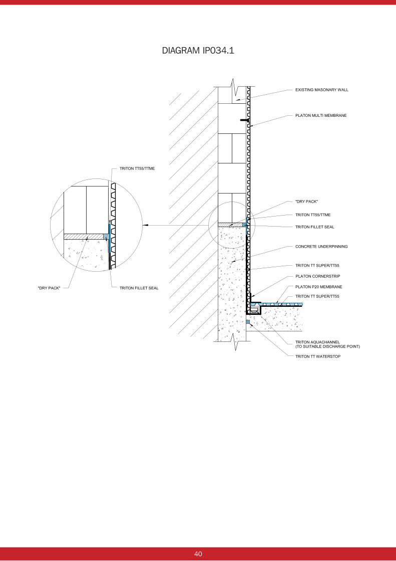
In most new construction and retrofit basements (and also in refurbishment projects where the floor has been replaced), there is a high risk of “FREE – LIME” and / or mineral salts leaching from the concrete walls and floors. In retrofit this is particularly prevalent where “dry pack” is used at the top of the underpinning.
As free lime leaches from the new construction by groundwater ingress it deposits itself within the drainage cavity, (behind and underneath membranes) and particularly within the sump chamber and around the sump pumps. Thus potentially causing pump failure and therefore failure of the cavity drain system.
Maintenance of the cavity drain system and its discharge points is vitally important to the long term success of the system, with the recommended maintenance interval being 6 months. (refer to Triton’s typical pump maintenance schedule).
The impact of free lime within the cavity drain system would greatly increase the frequency of maintenance over the first 3 – 5 years, reducing the interval to weeks in some instances, thus increasing both the costs of maintaining the system and also putting the system under undue risk.
In order to minimise the risk of free lime impacting on the cavity drain system, an “anti lime” coating should be applied to the concrete, such as TT Vapour membrane or TT Super. As shown in diagram TT009.1 (see page 39). For retrofit basements or where underpinning is being used we refer to drawing no. IP034.1 (see page 40).
This will not only reduce the amount of free lime leaching into the cavity drain system but also will improve the water resistance of the basement structure, which in turn reduces the risk to the cavity drain system.
For further information on Triton’s anti lime products or for assistance on designing these into a cavity drain system contact Triton’s technical department on 01322 318830.
Long term benefits include significantly reducing the risks to the cavity drain system and saving maintenance costs, see examples overleaf.
Typical problems caused by lime deposits

38
Example:
1. Existing basement with internal cavity drain system incorporating two sumps each with double pump system, maintained every six months.
Average cost of maintenance – approx £200 / sump / visit = £800 / annum
Over 10 years: £8,000 (minimum).
2. New build basement (concrete) with similar internal cavity drain system as above:
Maintained every 3 months in first 3 years, every 4 months in years 4 & 5, thereafter every six months:
Average cost of maintenance – £200 / sump / visit Years 1, 2 & 3 = £1600 / year Years 4 & 5 = £1200 / year Years 6 – 10 = £800 / year
Total maintenance cost for 10 years = £11,200 (minimum).
NOTE: A suitable Anti-Lime coating will dramatically reduce the associated problems of Free-Lime, whilst also dramatically reducing lime scale build up within both the drainage conduits and sump pump components.

39
DIAGRAM TT009.1
40
DIAGRAM IP034.1

41
Aqua Pump and Aqua Channel Service Schedule
Property address: Job Reference:
Date of Inspection: Contractor Name:
Aqua Channel Checked by: Further action required?
n Check for Debris
n Check Limescale/Silt
n Accumulation
n Check Jetting Eyes
n Flush out Channel
n Other
Aqua Pump (Minimum every 6 months) Checked by: Further action required?
n Clean silt/debris from sump
n Clean silt/debris from discharge pipes
n Check connections in discharge pipes
n Test discharge pipes
n Remove & inspect pump(s), wipe clean
n Check all pipe & electrical connections
n Test float mechanism, clean as required
n Check one way valve, clean & test
n Reinstate pump into sump & test
n Replace pump if/as required
Battery Back-Up Pump System (Minimum every 6 months)
Checked by: Further action required?
n Check all pipe and electrical connections, test
n Visually inspect & clean pump,isolate from mains pump and test, inc. pump float switch
n Check distilled water levels in battery,top up if necessary
Continued Overleaf...
42
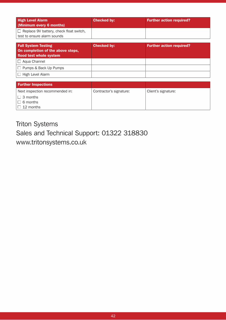
High Level Alarm (Minimum every 6 months)
Checked by: Further action required?
n Replace 9V battery, check float switch, test to ensure alarm sounds
Full System Testing On completion of the above steps, flood test whole system
Checked by: Further action required?
n Aqua Channel
n Pumps & Back Up Pumps
n High Level Alarm
Further Inspections
Next inspection recommended in:
n 3 monthsn 6 monthsn 12 months
Contractor’s signature: Client’s signature:
Triton SystemsSales and Technical Support: 01322 318830www.tritonsystems.co.uk

43
Pump Servicing And Maintenance:With the continued increase in installation of cavity drain membrane systems along with the required sumps, pumps and drainage channels, the success and failure of the systems relies on the installation and ongoing maintenance.
If an ongoing maintenance service is not available from the installing contractor, Triton can supply names of specialist servicing companies.
44
Cavity Drain Membrane Systems: Pre and Post Installation Checklist
Introduction:As with all waterproofing systems there is a need for adequate preparation before installation begins, this is also true for Isola Platon cavity drain membrane systems.
It is also important that the installation be tested during installation and at completion prior to handing the project over to the client. This is particularly relevant with cavity drain systems as they will always include sump and pump systems and in many cases drainage channels such as Triton Aqua Channel.
Where pumps, sumps and drainage channels are included within the waterproofing design, a suitable maintenance schedule and contract should be set up with the client. If the client does not wish the contractor to carry out such a maintenance regime, then it is important that they are made fully aware of the need for the pumps and drainage to be maintained.
An example of a typical maintenance schedule can be found in this manual, and it is the minimum required, this should be carried out at LEAST EVERY SIX MONTHS.
Below is a check list for pre and post installation of a Platon cavity drain membrane system.
The checklist below is by no means definitive, as this will vary with each project, and is intended as a guide.
Pre Installation:
• Remove all timber, wallpaper and organic materials from walls and floors.
• If timbers suffering from rot, once removed treat masonary with suitable masonary biocide.
• Remove all loose render / plaster from walls along with any other loose debris.
• Remove / lift all electrical and plumbing services.
• Mains boards gas / electric should only be lifted by the supplying company.
• All sharp objects / projections to be removed from walls and floors.
• Floors should be checked for level, ideally at fall to drainage / discharge points, any areas of ponding water floor to be made level.
• If floor is reinforced consult structural engineer prior to cutting any chases for drainage channels and holes for sumps.
Further initial preparation may be required.
Installation Checks:
• Ensure drainage channel runs to a fall towards discharge point.
• Inspection / rodding points are installed to drainage channel, change of direction every 12m.
• Ensure sumps pumps installed in accordance with installation guidelines.
• Flood test basement.
• Make any adjustments / improvements to drainage and pumps if / as indicated by flood test.
• Test to include drainage channels, sumps, pumps (all), alarms etc…
Install Isola Platon membranes to all walls and floors in accordance with this manual.
45
Post – Installation:
• Complete system to be flood tested
• Any modifications / repairs carried out.
• Re-test!
• Remove any debris from sump chamber.
• Set up maintenance schedule / contract with client, agreeing cost and frequency of maintenance.
• (Advise client of the necessity for ongoing maintenance if the have declined contractors maintenance contract).
System Maintenance:
The system needs to be fully maintained, a typical schedule can be found in this manual, the frequency of the maintenance should be every SIX MONTHS. If there is a lot of silt / sediment within the ingressing water or if there is new construction e.g. concrete then the frequency of servicing would need to be greater in the early years.
A cavity drain membrane system which is not maintained will be more prone to failure.
46
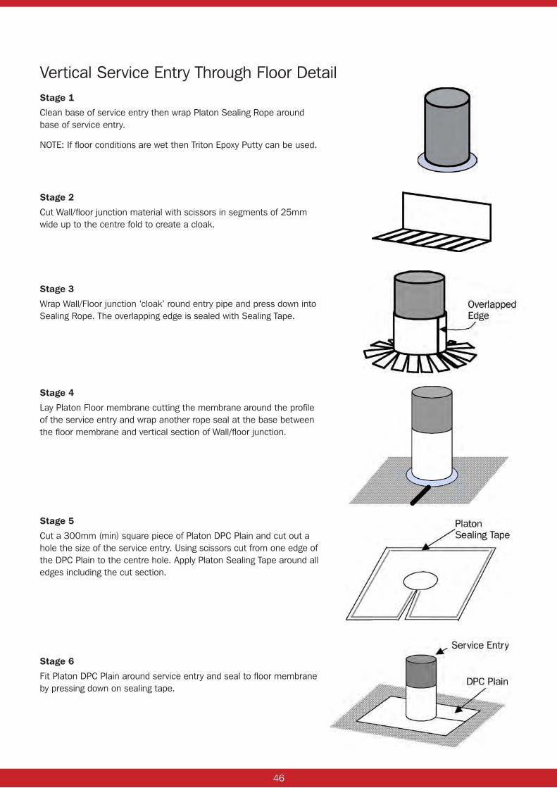
Vertical Service Entry Through Floor DetailStage 1
Clean base of service entry then wrap Platon Sealing Rope around base of service entry.
NOTE: If floor conditions are wet then Triton Epoxy Putty can be used.
Stage 2
Cut Wall/floor junction material with scissors in segments of 25mm wide up to the centre fold to create a cloak.
Stage 3
Wrap Wall/Floor junction ‘cloak’ round entry pipe and press down into Sealing Rope. The overlapping edge is sealed with Sealing Tape.
Stage 4
Lay Platon Floor membrane cutting the membrane around the profile of the service entry and wrap another rope seal at the base between the floor membrane and vertical section of Wall/floor junction.
Stage 5
Cut a 300mm (min) square piece of Platon DPC Plain and cut out a hole the size of the service entry. Using scissors cut from one edge of the DPC Plain to the centre hole. Apply Platon Sealing Tape around all edges including the cut section.
Stage 6
Fit Platon DPC Plain around service entry and seal to floor membrane by pressing down on sealing tape.

47
Horizontal Service Entries Through WallsPlaton Flextitett can be used to seal service entries where access is available to slot it over the item. This should be sealed using Sealing Rope around base, double sided tape between the Flextitett and the membrane and then overtaped with Corner Strip.

48
Product Specifications Isola Platon Cavity Drain Membranes:
• Platon Multi
• Platon P20
• Platon P5
• Platon P8
• Platon Mesh
• Platon Plasterbase
• Platon Double Drain
Isola Platon Fixing and Sealing Components:
• Platon Brick Plug
• Platon Plasterbase Plug
• Platon Fixing Cramps
• Platon Sealing Rope
• Platon Sealing Tape
• Platon Plasterbase Overtape
• Platon Wall/Floor Junction
• Wall Fixing Ties
Triton Drainage Products:
• Triton Aqua Pump (Single Sump & Pump Kit with Alarm and Aquapump Plus Kit)
• Triton Battery Back-up Pump System
• Triton Aqua Channel

49
System Platon – Product Specification
PLATON MULTI MEMBRANE
Description
Platon Multi Membrane is manufactured from translucent high-density polypropylene. It is impermeable and resistant to the usual chemicals in building construction.
When Platon Multi is acting as a damp proof membrane, both the product and the wall and floor coverings may be installed independent of the moisture content in the underlying structure and with running water not under pressure in the air gap.
Studs are formed in a regular pattern on one face of the membrane. The studs are round and spaced at 20mm centres. Platon Multi is supplied in rolls 2.05m x 20m.
Workability
Platon Multi Membrane is tough but pliable and can be bent round corners and projections without risk of breaking even in very low temperatures. The Membrane can be easily cut with a knife and scissors.
Storage
Rolls of Platon Multi should be stored upright.
Technical Data
Dimension: Roll 2.05m x 20m
Raw Material: PP (High Density Polypropylene)
Colour: Translucent
Stud Height: 5mm
Membrane Thickness: 0.5mm
Weight: 480 g/m²
Loading Performance: Defined by floor covering
Water vapour resistance: Approx. 1800m².s.Gpa/kg or 360n equivalent air layer.
Air Gap Volume: 3.3 l/m²
Filling Volume: 1.7 l/m²
Biological resistance: Does not rot or support growth
Chemical resistance: Resistant to all chemicals in normal building construction
Thermal resistance: 0.10 m².°K/W
Flammability: B2

50
System Platon – Product Specification
PLATON P20 MEMBRANE
Description
The Platon P20 Membrane is manufactured from black high-density polyethylene (PEH). It is impermeable and resistant to the usual chemicals in the building construction.
When the product acts as a damp proof membrane, both the product and floor coverings may be installed independent of the moisture content in the underlying concrete construction and with running water not under pressure in the air gap.
Studs are formed in a regular pattern on the one face of the Membrane. The studs are spaced at approx. 60mm centres. The product is supplied in rolls 2.0m x 20m.
Workability
The Platon P20 Membrane is tough but pliable and can be bent round corners and projections without risk of breaking even in very low temperatures. The Membrane can be easily cut with a knife or scissors.
Storage
Sheets of Platon P20 Membrane should be stored flat and rolls of P20 Membrane should be stored on end.
Technical Data
Sheet Thickness: Nominal 1.00mm
Stud Height (net): approx. 20mm
Unit Weight: 0.95 kg/m²
Tensile strength at yield: at least 10 N/mm²
Elongation at yield: at least 15%
Max. Compressive strength: 150 kN/m²
Deformation under long term load: max. 10% (load of 50 kN/m²)
Working Temperature: –50° to +80°C
Softening Temperature: +125°C
Linear Coefficient of thermal expansion: 0.13mm/m.°C
Life Expectancy: at least 50 years for defined applications.
Thermal Resistance: 0.17m².°C/W
Water Vapour Resistance: 3500m².s.Gpa/KG
Drainage Capacity: Max. 13 l/sm
Air Gap Volume: 14 litre/m²
Colour: Black
Chemical Resistance
The Platon P20 Membrane is resistant to all chemicals to which it can be exposed, in normal building construction. A small number of aggressive chemicals (e.g. solvents) in large concentrations, can to some extent attack the Platon P20 Membrane during prolonged exposure. If the product is to be applied, for example as cladding to storage tanks for aggressive chemicals, the supplier should be contacted, with a view to assessing necessary action.
For normal applications of the Platon P20 Membrane, relevant aggressive chemicals are very volatile, because of their very nature. This means that if they should come in contact with the Platon P20 Membrane, following an accident, they will evaporate of flow away from the construction without permanent damage occurring.

51
System Platon – Product Specification
PLATON P5 MEMBRANE
Description
The Platon Membrane is manufactured from black or clear "high density" polyethylene (PEH). It is impermeable and resistant to the usual chemicals in the building construction. Square shaped studs are formed in a regular pattern on the one face of the Membrane, and spaced at approx. 25 mm centres. The product is supplied in rolls of 20 m in length.
With the exception of 1 m wide rolls, rolls of the product are supplied with an area without formings along one of the edges of each width. This edge acts as the finish at the top edge on external basement walls, such that the edge is pressed against the wall on backfilling and this prevents fill materal from entering the air gap. When the product is used as Separation Board, the edge forms the overlap over the next roll width.
Workability
The Platon Membrane is tough but pliable and can be bent round corners and projections without risk of breaking even in very low temperatures. The Membrane can be easily cut with a knife or scissors.
Storage
Rolls of Platon Membrane should be stored upright when stored over long periods.
Technical Data
Sheet thickness: nominal 0.50 mm
Stud height (net): approx. 5 mm
Unit weight: 0.48 kg/m2
Tensile strength: at least 10 N/mm2
Elongation at yield: at least 10%
Max. compressive strength: 180 kN/m2
Deformation under long term loading: max. 25% (under load of 50 kN/m2)
Working temperature: –50° to +80°C
Softening temperature: +125°C
Linear coefficient of thermal expansion: 0.13 mm/m.°C
Life expectancy: at least 50 years for defined applications.
Thermal resistance: 0.10 m2.°C/W
Water vapour resistance: 1800 m2.s.GPa/kg or 350 m equivalent air layer.
Drainage capacity: max. 2.4 l/sm
Air volume: 3.25 liter/m2
Colour: Black or Clear
Chemical Resistance
The Platon Membrane is resistant to all chemicals, to which it can be exposed, in normal building construction.
A small number of aggressive chemicals (e.g. solvents), in large concentrations, can to some extent attack the Platon Membrane during prolonged exposure. If the product is to be applied, for example as cladding to storage tanks for aggressive chemicals, the supplier should be contacted, with a view to assessing necessary action.
52
System Platon – Product Specification
PLATON PLASTER BASE
Description
Platon Plaster Base is manufactured from natural high density polyethylene (PEH). It is impermeable and resistant to the usual chemicals in the building construction. The product acts as a damp proof membrane and key for the direct application of cement render or gypsum plaster.
The product and render or plaster may be installed independent of the moisture content in the underlying substrate.
Studs are formed in a regular pattern on the one face of the product, and form undercut cavities creating a key for render and plaster. The studs are spaced at approx. 35 mm centres. The product is supplied in rolls of 20 m in length.
Workability
Platon Plaster Base is tough but pliable and can be bent round corners and projections without risk of breaking even in very low temperatures. The product can be easily cut with a knife or scissors.
Storage
Rolls of Platon Plaster Base should be stored in unbroken packaging and upright, and preferably under cover, when stored over long periods.
Technical Data
Sheet thickness: nominal 0.50 mm
Stud height(net): approx. 5 mm
Unit weight: 0.48 kg/m2
Working temperature: –50° to +80°C
Softening temperature: +125°C
Linear coefficient of thermal expansion: 0.13 mm/m.°C
Thermal resistance: 0.10 m2.°C/W
Water vapour resistance: 1800 m2.s.GPa/kg or 350 m equivalent air layer.
Air gap volume: 3.2 litre/m2
Drainage capacity (transmissivity, i=1): max. 1.84 l/sm
Life expectancy: at least 50 years for defined applications.
Colour: Natural
Chemical Resistance
Platon Plaster Base is resistant to all chemicals, to which it can be exposed, in normal building construction.
A small number of aggressive chemicals (e.g. solvents), in large concentrations, can to some extent attack Platon Plaster Base during prolonged exposure. If the product is to be applied, for example as cladding to storage tanks for aggressive chemicals, the supplier should be contacted, with a view to assessing necessary action
53
System Platon – Product Specification
PLATON DOUBLE DRAIN DRAINAGE & PROTECTION MEMBRANE
Description
Platon Double Drain is a vertical drainage layer for external basement walls and a protection board to primary membranes. It consists of an impermeable studded sheet, manufactured from high-density polyethylene with a polypropylene filter fabric bonded to the top of the surface of the studs.
Channels between the studs form an air gap against the underlying structure. Platon Double Drain forms drainage layers on both sides of the studded core sheet. The filter fabric facing the backfill material ensures the drainage channels are not blocked or obstructed.
Storage
Rolls of Platon Double Drain should be stored upright.
Technical Data
Membrane: PEH
Filter Fabric: PP
Stud height: 7 mm
Membrane thickness: 0.5 mm
Weight: 590 g/m²
Drainage capacity: max 2.3 l/sm
Resistance to biological attack: Does not rot or support growth
Chemical resistance: Resistant to all chemicals in normal building construction
Membrane colour: Black
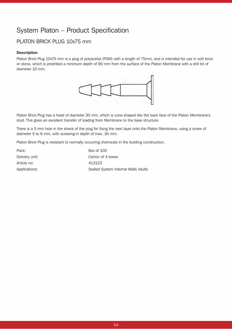
54
System Platon – Product Specification
PLATON BRICK PLUG 10x75 mm
Description
Platon Brick Plug 10x75 mm is a plug of polyacetal (POM) with a length of 75mm, and is intended for use in soft brick or stone, which is predrilled a minimum depth of 90 mm from the surface of the Platon Membrane with a drill bit of diameter 10 mm.
Platon Brick Plug has a head of diameter 30 mm, which is cone shaped like the back face of the Platon Membrane's stud. This gives an excellent transfer of loading from Membrane to the base structure.
There is a 5 mm hole in the shank of the plug for fixing the next layer onto the Platon Membrane, using a screw of diameter 5 to 6 mm, with screwing-in depth of max. 30 mm.
Platon Brick Plug is resistant to normally occurring chemicals in the building construction.
Pack: Box of 100
Delivery unit: Carton of 4 boxes
Article no: 413123
Applications: Sealed System Internal Walls Vaults

55
System Platon – Product Specification
PLASTER BASE FIXING PLUG 8x70 mm
Description
The Platon Plaster Base fixing plug is made of Polymer Co Polypropylene with a length of 70mm. It is intended for use in brick, concrete block and concrete, which is predrilled to a minimum depth 85mm from the surface of the Platon Plaster base membrane with an 8mm-diameter drill bit.
The head of the Plaster base plug has a diameter of 35mm with an embossed surface to provide a mechanical key for subsequent plaster/render. The Plaster Base fixing plug is resistant to normally occurring chemicals in the building construction.
Technical Data
Colour: opaque
Thickness: 8 mm
Length: 70mm
Working Temperature: –30°C to +90°C
Life expectancy: at least 50 years
Chemical resistance: as for Platon Membrane
NOTE: The fixing is not suitable for direct, long-term exposure to UV radiation
56
System Platon – Product Specification
PLATON DOUBLE DRAIN ‘X’ CRAMP
Description
Platon Double Drain ‘X’ Cramp is manufactured from black polyethylene.
The Double Drain ‘X’ Cramp fits precisely between four of Platon Double Drain’s studs and therefore transmits loading from Double Drain to the nail very effectively. It has a hole size of 3.5 mm diameter. The Double Drain ‘X’ Cramp has the same height as the net stud height.
For best fit and fixing strength, remove filter fabric from the area of Double Drain to be fixed, place and fix Double Drain ‘X’ Cramp, then replace filter fabric.
Platon Double Drain ‘X’ Cramp is resistant to normally occurring chemicals in the building construction.
Pack: Bag of 60
Delivery unit: Carton of 9 bags
Article no: 41 30 17
Applications: With Platon Double Drain on external basement walls.

57
PLATON MEMBRANE SEALING TAPE & ROPE
Key Features
Based on a blend of butyl and other rubbers, this versatile strip sealant has good tack and adhesion to most common surfaces whilst having good movement accommodation.
Standard colour – blue
Performance
The following performance data assumes good joint design. For non-standard situations refer to Technical Services Department.
Movement Accommodation: ±15% when used in lap and cover joints.
Adhesion: has good surface tack and adheres well to most building materials.
Shear Strength: 14N.
Compression (force required to compress by 20%): 200N
UV Light Resistance: Very Good.
Chemical Resistance: Good to diluted acids and alkalis. Not recommended for extreme chemical exposure.
Service Temperature Range: –40°C to +110°C.
Expected Life: The Sealing Tape & Rope is a durable material and can have a life in excess of 20 years depending on the service temperature and joint design.
Shelf Life: 1 year.
Elongation Of Break: 220%.
Application
Surface Preparation: All surfaces should be clean, dry and free from frost, grease and loose material.
Application Details: Should be applied directly from the reel onto one surface pressing sufficiently to ensure adequate initial adhesion. Remove backing paper and apply other surface onto Sealing Tape and Rope pushing firmly to ensure good contact with full area of strip along the length of the joint.
Application Temperature Range: +5°C to +30°C.
Priming: Primers are not required for good adhesion to most surfaces.
Packaging
Single strand reels on silicone release paper. Metres per reel and reels per carton depends on the thickness and width respectively.
Tolerance: Thickness: ± 10%
Width: up to 15mm ± 1mm 15-25mm ± 1.5mm over 26mm ± 2mm
Bead sections available in 10mm diameter.
Tolerance: Thickness: nominal to nominal less 12%
Width: nominal to nominal plus 12%
Health & Safety
There are no known health hazards associated with Platon Sealing Tape/Rope in normal use. Wash hands immediately after use.

58
PLATON PLASTER BASE FLEECEBAND OVERTAPE
Key Features
Based on a blend of butyl and other rubbers, this non woven fabric-backed versatile strip sealant has good tack and adhesion to most common surfaces whilst having good movement accommodation.
Standard colour – black with grey fleece
Performance
The following performance data assumes good joint design. For non-standard situations refer to Technical Services Department.
Movement Accommodation: ±15% when used in lap and cover joints.
Adhesion: has good surface tack and adheres well to PVC, many metals and plastic materials.
Shear Strength: 16.2N.
Compression To Seal: Positive Pressure
Force To Compress By 20%: 200N
UV Light Resistance: Excellent.
Chemical Resistance: Good to diluted acids and alkalis. Not recommended for extreme chemical exposure.
Service Temperature Range: –40°C to +110°C.
Expected Life: The Fleeceband overtape is a durable material and can have a life in excess of 20 years depending on the service temperature and joint design.
Shelf Life: 1 year.
Elongation Of Break: 220%.
Application
Surface Preparation: All surfaces should be clean, dry and free from frost, grease and loose material.
Application Details: Remove backing paper and apply directly from the reel onto membrane surface pressing firmly to ensure adequate adhesion along the length of the joint.
Application Temperature Range: +5°C to +45°C.
Priming: Primers are not required for good adhesion to most surfaces.
Packaging
Single strand reels on silicone release paper. Metres per reel and reels per carton depends on the thickness and width respectively.
Tolerance: Thickness: ± 10%
Width: ± 2mm
Health & Safety
There are no known health hazards associated with P5 Sealing Tape/Rope in normal use. Wash hands immediately after use.
59
System Platon – Product Specification
PLATON WALL/FLOOR JUNCTION FOR SEALED SYSTEM
Description
Platon Wall/Floor Junction is manufactured from black High Density Polyethylene (PEH). It is impermeable and used to provide a continuous seal between two adjacent sheets of Platon Membrane with Platon Sealing Tape around external (or internal) corners in walls or similar projections. Installation is carried out simply by folding the product along the preformed crease, and placing with the flat face towards the Platon Membrane on each adjacent wall surface.
Wall/Floor Junction is supplied in lengths of 2 m with a preformed crease for the fold line along the centre line. 10 lengths rolled up together.
Workability
Platon Wall/Floor Junction is easily cut with a knife or scissors.
Storage
Over long periods Platon Wall/Floor Junction should be stored indoors, standing as a roll in unopened packs, and not exposed to direct sunlight.
Technical Data
Colour: black
Thickness: 0.6 mm
Width: 300 mm
Weight: approx. 0.80 g/m
Working Temperature: –50°C to +80°C
Linear coefficient of thermal expansion: 0.13 mm/m°C
Life expectancy: at least 50 years
Water vapour resistance: 1800 m2.s.GPa/kg
Chemical resistance: as for Platon Membrane
Sizes/Article no. Length of 1.30 m 414101
Delivery unit Roll of 10 lengths
Applications: Sealed System

60
System Platon – Product Specification
PLATON CORNER STRIP
Key Features
Based on a blend of butyl and other rubbers, this versatile strip sealant has excellent high tack adhesion and will adhere to most common surfaces whilst having good movement accommodation.
Standard colour – white adhesive base with aluminium lead look top surface
Performance
The following performance data assumes good joint design. For non-standard situations refer to Technical Services Department.
Movement Accommodation: ±5% when used in lap and cover joints.
Adhesion: has excellent surface tack and adheres well to PVC, many metals and plastic surfaces.
Shear Strength: 14N.
Compression To Seal: Positive Pressure
UV Light Resistance: excellent.
Chemical Resistance: Good to diluted acids and alkalis. Not recommended for extreme chemical exposure.
Service Temperature Range: –40°C to +90°C.
Expected Life: The Sealing Tape & Rope is a durable material and can have a life in excess of 15 years depending on the service temperature and joint design.
Shelf Life: 1 year.
Elongation Of Break: 220%.
Application
Surface Preparation: All surfaces should be clean, dry and free from frost, grease and loose Material.
Application Details: Remove backing paper and apply directly from the reel onto membrane surface pressing firmly to ensure adequate adhesion along the length of the joint.
Application Temperature Range: +2°C to +30°C.
Priming: Primers are not required for good adhesion to most surfaces.
Packaging
Single strand reels on silicone release paper. Metres per reel and reels per carton depends on the thickness and width respectively.
Health & Safety
There are no known health hazards associated with Platon Corner Strip in normal use. Wash hands immediately after use.
61
TRITON AQUA PUMP SYSTEM
Description And Use
When installing Isola Platon Cavity Drainage membranes careful attention must be given to provide a suitable drainage solution. Natural drainage is not normally possible or convenient in below ground situations, so mechanical drainage must be used.
TRITON AQUA PUMP is a ready to use complete water control system principally designed for use in below ground structures to control water ingress. The system consists of a pre-formed polyethylene sump basin, a mains powered 230v submersible pump, a non-return valve assembly and a battery operated high water level alarm, which is linked to an integral float switch. The TRITON AQUA PUMP system can be linked to TRITON AQUA CHANNEL (see Triton Aqua Channel Data)managing water ingress from retaining walls and in turn pumping out to a suitable drainage point.
IMPORTANT NOTE: The Triton Aqua Pump must only be used for pumping ground water. The pump should not be used to pump grey water from; sinks/washing machines/dishwashers/condensing boilers or effluent. Triton Chemical Manufacturing Ltd will not accept responsibility or liability for pump failure or damage caused due to the misuse of the pumping system.
Components
SUMP BASIN – The Sump Basin is a polyethylene pre-formed chamber, measuring 560mm high x 540mm diameter (top) x 460mm diameter (base) and is most commonly located into the floor, finishing flush with the surrounding floor level. The Sump Basin is supplied with a structural foam flat lid, which can accept foot traffic. The lid can be easily removed to allow regular maintenance of the internal submersible pump or pumps.
SUBMERSIBLE PUMP – The pump is positioned within the Sump Basin and is controlled by an automatic snap-action float switch. As the water level increases within the sump the float rises and when the pre-set switch level is reached the pump will automatically operate and discharge the water. The Pump is 230v and requires wiring into an independent fused spur outlet within 1.5m of the pump.
Pump Specification
Discharge Bore: 38.1mm
Max. Head: 6m
Max. Capacity: 220 litres/min @ 1m
Motor Output: 1/3 Hp
Max.Width: 214mm
Max.Height: 258mm
Max Depth: 270mm
Voltage: 230v
Fuse rated: 5.0amp
NON-RETURN VALVE ASSEMBLY – To avoid any discharged water backing-up into the sump basin, a non-return valve assembly is provided. This is fitted directly to the submersible pump outlet via flexible couplings and supplied ready to accept a standard 1½” waste pipe.
HIGH WATER LEVEL ALARM – The High Water Level Alarm is an essential component within the Aqua Pump system. In the event of mechanical failure of the pump or an unexpected power failure, the water will continue to fill the sump. When the water reaches the level of the alarm float switch, the 80db alarm will sound, giving warning of the failure.
The alarm is powered by a 9v battery, which should be positioned in a convenient location such as a kitchen/lounge where it will be easily heard. Once the alarm is heard immediate action must be taken to avoid flooding. Additionally a 12v battery operated pump can be installed offering peace of mind to the client, while investigations are made into the failure. See Triton Battery Back-up Pump System data.
62
Preparation And Installation
The site conditions or situation being encountered may well determine the positioning of the Triton Aqua Pump System. However, ideally it should be sighted at the lowest point of the room and or closest to the nearest point where water will be discharged. The most important thing is to make sure that water can get to the pumping station. Once the pump position has been established, dig a circular hole to a depth of 650mm and to a width of 650mm.
At the base of the sump basin, drill 4 holes (12mm dia) opposite to each other. Cut two lengths of reinforcing bar (660mm long) and insert through holes at base of sump basin.
Fit the high water level alarm float switch sensor into the pre-cut hole provided within the wall of the sump basin and ensure that the (jaw) of the switch sensor is open and hangs downwards. Bring the two cables with bullet connectors attached back into the sump basin either through one of the holes provide or by drilling a hole and leave ready to be connected to the wires of the water alarm. NB: if the water discharge pipe from the pump is to be concealed below the floor, then a 1½" hole will need to be cut through the side of the basin. However, the position of this hole can only be determined once the sump basin has been offered into position, otherwise the discharge pipe can be taken through the lid of the basin.
Lay 100mm concrete in the base of the hole and insert the sump basin. Using a spirit level, adjust the top of the basin to the level of the finished floor level .Fill the sump basin two thirds with water. Then fill around sides of sump basin with concrete. NB: If Platon membrane is being installed over the floor, then the concrete will need to finish approx 100mm below top of sump basin, the top of the sump basin to be perforated and then the void above the concrete to be filled with 20mm stone. However, IF Platon membrane is not going to be installed over the floor, the concrete to be finished flush with top of sump basin. (see drwg no. IP029.1).
Insert the Aqua Pump in the base of the sump basin and connect the water discharge pipe to the flexible coupling already attached to the pump. The discharge end of the pipe can be taken through a wall and extended to a gully outlet at ground/street level. Alternatively, the discharge pipe can be connected straight into a soil pipe using a ‘boss’ connection. Where a double pump installation is being used (Aqua Pump Plus), each pump must be wired into an independent fused spur outlet. One of the Aqua Pumps (the secondary pump) in the double pump kit will have been fitted with 25mm long spacers at the base of the pump so that this pump is raised off the bottom of the sump basin.
Connect the wires from the float switch sensor to the wires of the water alarm using the bullet connectors provided. Then connect the pump/s power cable into a fused spur outlet (fuse rating 5amp) and test the pump and alarm for working order.
NOTE: If there is any concern as to whether there is a risk of de-watering the ground to a condition whereby the structure as a whole could or may be undermined, then advice should be sought from a chartered engineer.
Maintenance
It is recommended that the Triton Aqua Pump System is maintained /serviced at a minimum every six months. This should be carried out by a competent contractor (under a maintenance contract) or by the property owner. During a service all parts of the Aqua Pump kit should be checked to ensure fully operational. The sump should be cleared of any silt/sludge that may have accumulated to avoid potential damage to the pump/s.
The sump must be filled with water to ensure the automatic float switch and pump are fully operational. We recommend renewal of the 9v battery within the alarm and that the alarm float switch checked to ensure the alarm sounds. Any defective parts must be replaced /repaired to avoid failure of the system. An Example of a suitable maintenance schedule can be found in the appendix at the back of this manual.
We recommend records of each service be kept by the property owner.
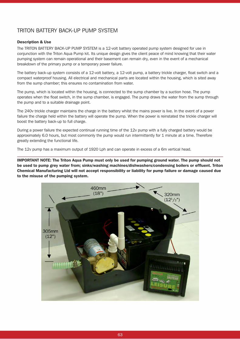
63
TRITON BATTERY BACK-UP PUMP SYSTEM
Description & Use
The TRITON BATTERY BACK-UP PUMP SYSTEM is a 12-volt battery operated pump system designed for use in conjunction with the Triton Aqua Pump kit. Its unique design gives the client peace of mind knowing that their water pumping system can remain operational and their basement can remain dry, even in the event of a mechanical breakdown of the primary pump or a temporary power failure.
The battery back-up system consists of a 12-volt battery, a 12-volt pump, a battery trickle charger, float switch and a compact waterproof housing. All electrical and mechanical parts are located within the housing, which is sited away from the sump chamber; this ensures no contamination from water.
The pump, which is located within the housing, is connected to the sump chamber by a suction hose. The pump operates when the float switch, in the sump chamber, is engaged. The pump draws the water from the sump through the pump and to a suitable drainage point.
The 240v trickle charger maintains the charge in the battery whilst the mains power is live. In the event of a power failure the charge held within the battery will operate the pump. When the power is reinstated the trickle charger will boost the battery back-up to full charge.
During a power failure the expected continual running time of the 12v pump with a fully charged battery would be approximately 6.0 hours, but most commonly the pump would run intermittently for 1 minute at a time. Therefore greatly extending the functional life.
The 12v pump has a maximum output of 1920 Lph and can operate in excess of a 6m vertical head.
IMPORTANT NOTE: The Triton Aqua Pump must only be used for pumping ground water. The pump should not be used to pump grey water from; sinks/washing machines/dishwashers/condensing boilers or effluent. Triton Chemical Manufacturing Ltd will not accept responsibility or liability for pump failure or damage caused due to the misuse of the pumping system.
64
TRITON BATTERY BACK-UP PUMP INSTALLATIONPosition the Battery Back-up Pump kit in the desired location.
NOTE: The flexible suction hose should not be extended greater than 1.8m from the base of the sump chamber.
Run the flexible suction hose from the sump chamber (allowing approximately 50mm of hose off the base of the sump) and secure the hose to the side of the chamber with the clips provided.
Connect the outer end of the flexible suction hose to the pump inlet with the jubilee clip provided and secure tight.
The battery pumps float switch is secured within the chamber to the vertical discharge pipe that extends from the primary pump, with a nut and bolt-clamping bracket. This will normally be pre-fixed in place around a section of vertical discharge pipe when delivered with a primary pump i.e. the Aqua pump kit or Aqua Pump Plus Kit. If it is found that the float switch and clamping bracket are not pre-fixed around a section of vertical discharge pipe, then the float switch and clamping bracket must be fitted, positioned and adjusted so as to ensure there is free movement of the float switch in the sump chamber.
Connect the battery pump float switch cable/wire to the connector block located inside the back-up pump housing.
Solvent weld the discharge pipe to the pump outlet and connect this water discharge pipe to a suitable drainage point: Drainage Gulley, Stack pipe using a ‘Boss Connector’ or T-Connector.
Connect each battery cable to the correct battery terminal and tighten the connector bolts and then plug-in the battery charger to the power supply. The battery will begin to charge.
The battery charge state is indicated by the L.E.D display on the charger. Once the battery is charged, fill the sump chamber with water and test the battery back-up system several times to ensure it is fully operational.
Maintenance
It is recommended that the Triton Battery Back up system is maintained /serviced at a minimum every six months. This should be carried out by a competent contractor (under a maintenance contract) or by the property owner. During this service the principle pump/s should be temporarily isolated then the battery back-up pump float switch should be tested and checked it is working properly. The sump chamber should be filled with water and the battery back-up pump should be run so that the water is discharged from the sump chamber, which ensures that the pump is fully operational.
The distilled water levels within the battery should be checked and topped up as necessary to ensure the cells do not run dry. Any defective parts must be replaced /repaired to avoid failure of the system.
We recommend records of each service be kept by the property owner.
65
TRITON AQUA CHANNEL
Description & Use
TRITON AQUA CHANNEL is a P.V.C drainage conduit designed for the control of water ingress in below ground situations.
TRITON AQUA CHANNEL is fitted around the perimeter of the floor at the vulnerable wall/floor junction.
TRITON AQUA CHANNEL can be used in most waterproofing situations, and is particularly suited for use in conjunction with Isola Platon Cavity Drain Membrane systems. Water entering the building through the walls is controlled behind the Platon Membrane and diverted to the Aqua Channel at the base of the wall. The water enters the Aqua Channel through pre-drilled 19mm holes drainage holes set 70mm apart along its length and is then be diverted to a suitable drainage point, either natural or a sump and mechanical pump (see Triton Aqua Pump). Jetting eyes and channel to sump connector’s can also be fitted into the perimeter drainage system to enable the Aqua Channel to be cleaned periodically if necessary.
In situations where an existing floor slab/screed is solid and showing no signs of water ingress, cracking or de-bonding, the installation of Aqua Channel can eliminate the need for Platon Cavity Drain membrane on the floor, proving beneficial in areas of limited headroom.
The application of a liquid waterproof coating to the existing floor would be recommended to act as a moisture suppressant.
Pump And Drainage Accessories:
AQUA CHANNEL ACCESSORIES:
1. Channel Outlet.
The channel outlet consists of a 90 degree bend and male coupling fitted to the base of Aqua Channel, to allow the water to be taken from the channel to the water collection point i.e. sump and pump. The swivel action of the channel outlet enables flexibility, which is sometimes needed, when taking into consideration the positioning of the sump and pump.
The channel outlet is pre-fitted to a 200mm section of Aqua Channel, and can be easily installed into a run of Aqua Channel.
2. Channel End Outlet.
Where gravity fed drainage is to be used, or externally located sump and pump, the channel end outlet has been designed to offer a round 40mm aperture. This enables water to be discharged from the Aqua Channel into a “p” trapped gully, soakaway, or sump and pump.
NOTE: the Channel End Outlet should not be used to drain water from the Aqua Channel directly into foul drainage or stack pipe.
The Channel End Outlet is pre-fitted to a 200mm section of Aqua Channel for ease of connection.
3. Cleaning Ports.
Cleaning Ports (jetting eyes) should be incorporated into the Aqua Channel to allow for periodic cleaning of the drainage system. A 40mm straight connector is fitted to the top of the channel, with a removable cap and rubber seal. The length of the straight connector can be varied to suit floor depth requirements. It is recommended that one Cleaning Port be installed for every 12 linear meter run of Aqua Channel installed.
The Cleaning Ports are pre-fitted to a 200mm section of Aqua Channel and can easily be inserted into a run of Aqua Channel.
For further specific details on the above please see Aqua Channel details in the appendix of this manual.
66
4. P20 Cleaning Ports.
Where surface drainage channels have been installed to floors under Platon P20 floor membrane, these also require cleaning periodically as part of general maintenance of the cavity drain system. P20 cleaning ports consist of a 40mm straight connector with removable cap and rubber seal to be welded to a male coupling, fitted to a 300mm square of Platon P20 membrane. Simply installed into the Platon P20 floor membrane, and sealed using either Platon Sealing Rope, or Over Tape. P20 Cleaning Ports to be located over surface drainage gullies, and approximately every 20 square meters of floor area.
PUMPS AND ALARMS:
5. Triton Aqua Pump Pro
The Triton Aqua Pump Pro is specially designed for the removal of ground water from basement cavity drain membrane systems. Comprising polyethylene sump, locking access cover and a powerful submersible pump, the system is very versatile enabling installers to locate inlets to their specifications.
• Quick and easy to install
• Maximum head 7m
• Pump capacity 132 litres/minute
NOTE: All pumps should be wired to their own independent fused spur.
6. Triton Aqua Pump Pro Plus
The Triton Aqua Pump Pro Plus is identical to the Aqua Pump Pro system above but is supplied with two mains powered pumps. These can be plumbed to either a single discharge outlet or to two separate outlets from the sump. The second mains pump is located on the raised foot within the chamber and provides back up to the primary pump and additional capacity to the system if required.
NOTE: All pumps should be wired to their own independent fused spur.
7. Triton Aqua Pump Pro Battery Back Up
The Aqua Pump Pro Battery Back Up system comprises a polyethylene sump, locking access cover, powerful submersible pump, 24v back up pump and control panel. It is designed for use where primary pump failure through mechanical fault of loss of mains power would be catastrophic. The system alerts the end user if the water rises above the normal operating level within the sump, and activates the back up pump via three separate float switches. The panel contains two trickle charged batteries.
• Control panel can be located up to 20m from sump
• Easy to install
• Back up and mains powered pump have similar capacity
• Maximum head 6.5m
• Maximum pump capacity 180 litres/minute
NOTE: All pumps should be wired to their own independent fused spur.
67
8. Tsurumi 50PU2 Automatic.
Stainless steel motor frame and hi-tech plastic upper and lower casing for excellent corrosion and wear resistant performance. 230V with automatic float mechanism. For use where higher flow rate or head height is required. (see pump, sump, guidance notes in appendix of this manual).
Specification:
Max Head: 9.5m
Max Capacity: 270 l / min
9. Utility Puppy 3000.
12V Battery operated pump, to be located within the Triton battery back up housing, and connected to the sump chamber by way of suction hose. For use where greater capacity or head height is required.
Specification:
Max Head: 8m
Max Capacity: 2580 lph
10. Generator Back Up.
A gas converted EU30 Honda generator, with auto change over for when mains power fails. For use in high risk areas or remote areas where power failures may occur for longer periods. When fitted with 12K gas bottle will provide power to the pumps for up to 30 Hours.
Strictly Available To Order Only.
11. Dialler Alarm.
A 240v alarm c/w 2m cable and 13 amp plug. Metal casing approx 210 x 260 x 80mm, IP40 protection, Dialler complete with BT connection plug and cable, up to 4 contact numbers, and pre recorded message on alarm. 4 inputs and LCD display.

68
Index Of Cad Drawings: – Platon Membrane Systems
TYPICAL APPLICATIONS:IP 002.1 Typical wall/floor detailing below ground
IP 012.1 Internal membrane to walls Triton TriSeal to floors
IP 013.1 Typical sump/pump/Aqua Channel and membrane installation
IP 024.1 Drainage options to reinforced concrete floors
IP 025.1 Flat soffits
IP 029.1 Sump installation options
NEW BUILD BASEMENTS:IP 014.1 Installation of load bearing walls to Platon membranes
IP 035.1 Platon Cavity Drain System New Build Concrete Basement
TT/IP 048.1 Waterproofing Options - Subterranean Room Combination System
IP 049.1 Platon Double Drain To External Basement Walls
FIXING/SEALING DETAILS:IP 026.1 Window/door reveal detail
IP 027.1 Service pipe sealing detail
IP 032.1 Sealing Detail Platon Membrane To ‘I’ Beam
RETROFIT:IP 034.1 Platon Membrane To Underpinning Detail
Additional drawings are available on request and also in CAD format if required.
If you require more specific project related drawings then please contact our technical department on 020 8310 3929 or visit www.triton-chemicals.com
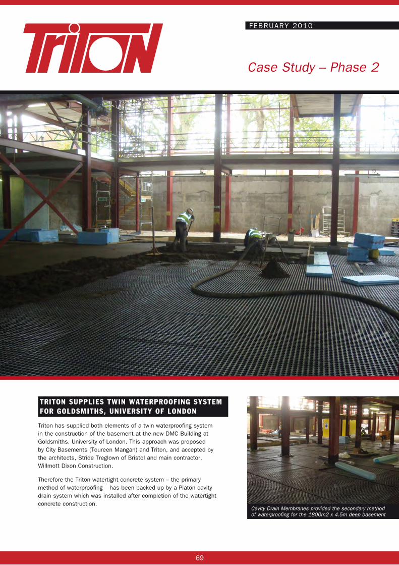
69
Case Study – Phase 2
FEBRUARY 2010
TRITON SUPPLIES TWIN WATERPROOFING SYSTEM FOR GOLDSMITHS, UNIVERSITY OF LONDON
Triton has supplied both elements of a twin waterproofing system in the construction of the basement at the new DMC Building at Goldsmiths, University of London. This approach was proposed by City Basements (Toureen Mangan) and Triton, and accepted by the architects, Stride Treglown of Bristol and main contractor, Willmott Dixon Construction.
Therefore the Triton watertight concrete system – the primary method of waterproofing – has been backed up by a Platon cavity drain system which was installed after completion of the watertight concrete construction.
Cavity Drain Membranes provided the secondary method of waterproofing for the 1800m2 x 4.5m deep basement
Case Study – new build

70
Phase 1 involved the specification of Triton’s TT Super Admix to produce 900m³ of watertight concrete used in the construction of the concrete capping beam to the top of the piles, the reinforced concrete liner walls (150mm – 200mm) and the reinforced concrete floor slab (300mm). All construction joints to the capping beam, wall capping beam, wall/floor and floor/floor joints were waterproofed with Triton’s TT Swellmastic and TT Waterstop forming a completely watertight concrete system.
Phase 2 of this major waterproofing project involved the installation of a cavity drain membrane system. Although a watertight concrete system had been specified as described above, when this type of system is used alone, it can still be compromised by shrinkage, thermal cracking and poor joint detailing, leading to leaks which need to be repaired - and the leaks will only become apparent when water comes to bear on the structure.
Platon Cavity Drain Membranes were therefore specified as the second element to provide the extra security of a twin waterproofing system. Cavity Drain Membranes work on the principle of allowing water to continue to penetrate a structure but control it in the air gap between the structure and their studded profile and divert it to a suitable drainage point. They do not allow pressure to build up against the internal construction and the air gap behind the membrane allows the structure to breathe and to some extent to dry out. Cavity drain membranes are lose laid on floors and fixed to walls using special plugs and sealing materials.Once the membrane has been fitted, wall surfaces can be dry lined or plastered directly and floors can be screeded or a floating dry board system installed.
At Goldsmiths, 800m² of Platon Multi, a BBA accredited, 5mm Polypropylene membrane, was applied to the walls. 1800m² of heavy duty Platon P20, a deeper studded HDPE membrane, was laid to the floors. 300 linear metres of Triton Aquachannel (a drainage conduit fitted to the perimeter of the basement at the wall/floor junction) was laid to direct any water which may ingress behind the membrane to the sumps.
The basement will house two lecture theatres, TV and photographic studios and associated areas. The basement is 4.5m deep and extends to the complete 1800m² footprint of the new, two storey building above.
www.citybasements.comwww.toureenmangan.co.uk
Case Study – Phase 2
FEBRUARY 2010
Platon P20 was loose laid to the new basement floor
Platon Multi was installed to the walls
A screed can be applied directly to cavity drain membranes laid on the floor
Triton Chemical Manufacturing Co. Ltd. Unit 5, Lyndean Industrial Estate, Abbey Wood, London SE2 9SG
Tel: 020 8310 3929 Fax: 020 8312 0349 Email: [email protected]
www.triton-chemicals.com
Triton SystemsUnits 3 – 5 Crayford Commercial Centre, Greyhound Way, Crayford, Kent DA1 4HF
Tel: 01322 318830Fax: 01322 524017Email: [email protected]
www.tritonsystems.co.uk

71
JUNE 2010
RETROFIT BASEMENT FOR VICTORIAN PROPERTY
Triton approved contractors, Midlands based Dampco, extended an existing basement to create a large habitable space beneath a detached Victorian double bay property. There was already a basement beneath 60% of the property and excavation was undertaken to extend it over a further 30m². There were no existing lightwells and the DampCo team installed five, with the excavated earth being removed via the new ones at the front of the property.
Large areas of underpinning were involved with the earth taken down to achieve a 2.5m head height. Two internal partition walls were built and some existing internal walls removed to suit the new internal layout.
The original basement was increased by a further 30m2
Case StudyCase Study – existing basement
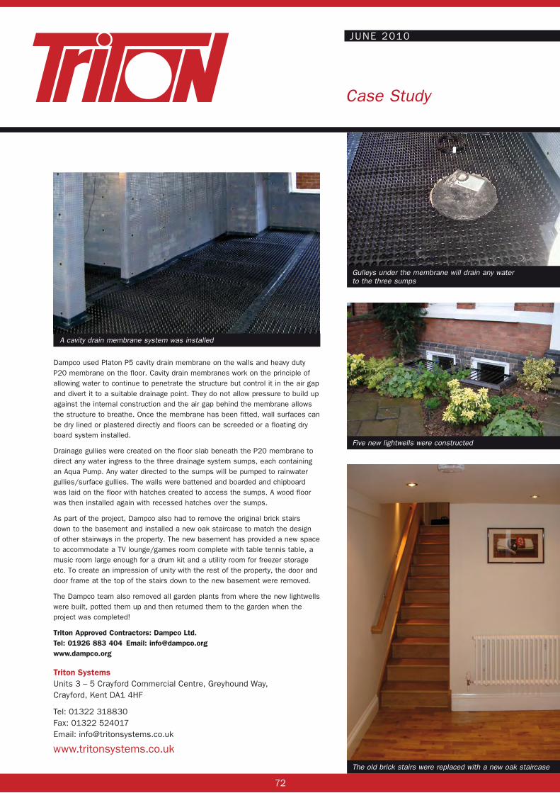
72
JUNE 2010
Five new lightwells were constructed
Gulleys under the membrane will drain any water to the three sumps
Case Study
The old brick stairs were replaced with a new oak staircase
Triton Chemical Manufacturing Co. Ltd. Unit 5, Lyndean Industrial Estate, Abbey Wood, London SE2 9SG
Tel: 020 8310 3929 Fax: 020 8312 0349 Email: [email protected]
www.triton-chemicals.com
Dampco used Platon P5 cavity drain membrane on the walls and heavy duty P20 membrane on the floor. Cavity drain membranes work on the principle of allowing water to continue to penetrate the structure but control it in the air gap and divert it to a suitable drainage point. They do not allow pressure to build up against the internal construction and the air gap behind the membrane allows the structure to breathe. Once the membrane has been fitted, wall surfaces can be dry lined or plastered directly and floors can be screeded or a floating dry board system installed.
Drainage gullies were created on the floor slab beneath the P20 membrane to direct any water ingress to the three drainage system sumps, each containing an Aqua Pump. Any water directed to the sumps will be pumped to rainwater gullies/surface gullies. The walls were battened and boarded and chipboard was laid on the floor with hatches created to access the sumps. A wood floor was then installed again with recessed hatches over the sumps.
As part of the project, Dampco also had to remove the original brick stairs down to the basement and installed a new oak staircase to match the design of other stairways in the property. The new basement has provided a new space to accommodate a TV lounge/games room complete with table tennis table, a music room large enough for a drum kit and a utility room for freezer storage etc. To create an impression of unity with the rest of the property, the door and door frame at the top of the stairs down to the new basement were removed.
The Dampco team also removed all garden plants from where the new lightwells were built, potted them up and then returned them to the garden when the project was completed!
Triton Approved Contractors: Dampco Ltd.Tel: 01926 883 404 Email: [email protected]
A cavity drain membrane system was installed
Triton SystemsUnits 3 – 5 Crayford Commercial Centre, Greyhound Way, Crayford, Kent DA1 4HF
Tel: 01322 318830Fax: 01322 524017Email: [email protected]
www.tritonsystems.co.uk

73
Trito
n Sy
stem
sU
nits
3 –
5 C
rayf
ord
Com
mer
cial
Cen
tre,
Gre
yhou
nd W
ay, C
rayf
ord,
Ken
t DA1
4H
F
Tel:
0132
2 31
8830
Fax:
01
322
5240
17Em
ail:
info
@tri
tons
yste
ms.
co.u
kw
ww.
trito
nsys
tem
s.co
.uk
THIS
DR
AWIN
G IS
TH
E PR
OPE
RTY
OF
TR
ITO
N S
YSTE
MS
AND
MU
ST N
OT
BE L
OAN
ED O
R
CO
PIED
WIT
HO
UT
PRIO
R W
RIT
TEN
CO
NSE
NT
© 2
006
TRIT
ON
SYS
TEM
S
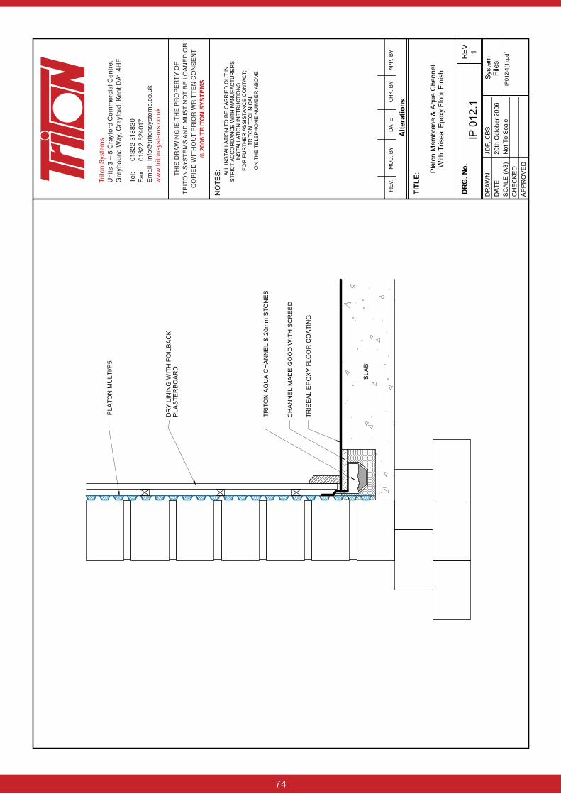
74
Trito
n Sy
stem
sU
nits
3 –
5 C
rayf
ord
Com
mer
cial
Cen
tre,
Gre
yhou
nd W
ay, C
rayf
ord,
Ken
t DA1
4H
F
Tel:
0132
2 31
8830
Fax:
01
322
5240
17Em
ail:
info
@tri
tons
yste
ms.
co.u
kw
ww.
trito
nsys
tem
s.co
.uk
THIS
DR
AWIN
G IS
TH
E PR
OPE
RTY
OF
TR
ITO
N S
YSTE
MS
AND
MU
ST N
OT
BE L
OAN
ED O
R
CO
PIED
WIT
HO
UT
PRIO
R W
RIT
TEN
CO
NSE
NT
© 2
006
TRIT
ON
SYS
TEM
S

75
Trito
n Sy
stem
sU
nits
3 –
5 C
rayf
ord
Com
mer
cial
Cen
tre,
Gre
yhou
nd W
ay, C
rayf
ord,
Ken
t DA1
4H
F
Tel:
0132
2 31
8830
Fax:
01
322
5240
17Em
ail:
info
@tri
tons
yste
ms.
co.u
kw
ww.
trito
nsys
tem
s.co
.uk
THIS
DR
AWIN
G IS
TH
E PR
OPE
RTY
OF
TR
ITO
N S
YSTE
MS
AND
MU
ST N
OT
BE L
OAN
ED O
R
CO
PIED
WIT
HO
UT
PRIO
R W
RIT
TEN
CO
NSE
NT
© 2
006
TRIT
ON
SYS
TEM
S
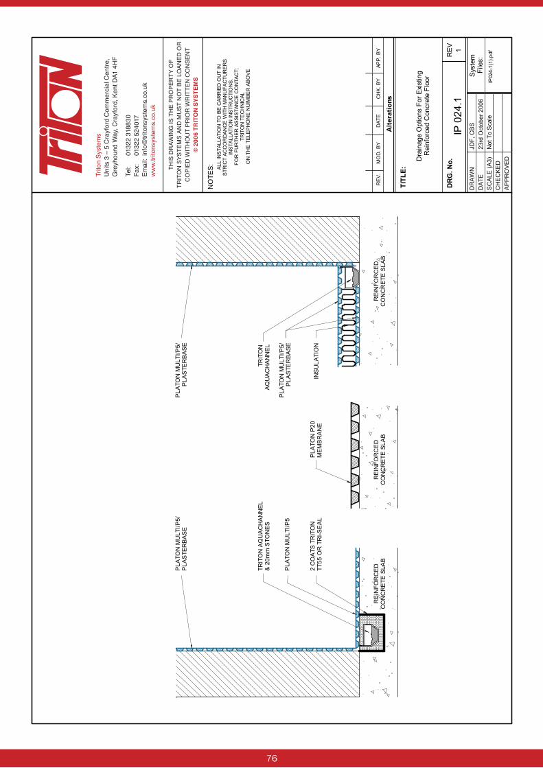
76
Trito
n Sy
stem
sU
nits
3 –
5 C
rayf
ord
Com
mer
cial
Cen
tre,
Gre
yhou
nd W
ay, C
rayf
ord,
Ken
t DA1
4H
F
Tel:
0132
2 31
8830
Fax:
01
322
5240
17Em
ail:
info
@tri
tons
yste
ms.
co.u
kw
ww.
trito
nsys
tem
s.co
.uk
THIS
DR
AWIN
G IS
TH
E PR
OPE
RTY
OF
TR
ITO
N S
YSTE
MS
AND
MU
ST N
OT
BE L
OAN
ED O
R
CO
PIED
WIT
HO
UT
PRIO
R W
RIT
TEN
CO
NSE
NT
© 2
006
TRIT
ON
SYS
TEM
S
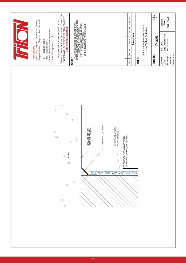
77
Trito
n Sy
stem
sU
nits
3 –
5 C
rayf
ord
Com
mer
cial
Cen
tre,
Gre
yhou
nd W
ay, C
rayf
ord,
Ken
t DA1
4H
F
Tel:
0132
2 31
8830
Fax:
01
322
5240
17Em
ail:
info
@tri
tons
yste
ms.
co.u
kw
ww.
trito
nsys
tem
s.co
.uk
THIS
DR
AWIN
G IS
TH
E PR
OPE
RTY
OF
TR
ITO
N S
YSTE
MS
AND
MU
ST N
OT
BE L
OAN
ED O
R
CO
PIED
WIT
HO
UT
PRIO
R W
RIT
TEN
CO
NSE
NT
© 2
006
TRIT
ON
SYS
TEM
S

78
Trito
n Sy
stem
sU
nits
3 –
5 C
rayf
ord
Com
mer
cial
Cen
tre,
Gre
yhou
nd W
ay, C
rayf
ord,
Ken
t DA1
4H
F
Tel:
0132
2 31
8830
Fax:
01
322
5240
17Em
ail:
info
@tri
tons
yste
ms.
co.u
kw
ww.
trito
nsys
tem
s.co
.uk
THIS
DR
AWIN
G IS
TH
E PR
OPE
RTY
OF
TRIT
ON
SYS
TEM
S AN
D M
UST
NO
T BE
LO
ANED
OR
CO
PIED
WIT
HO
UT
PRIO
R W
RIT
TEN
CO
NSE
NT
© 2
007
TRIT
ON
SYS
TEM
S

79
For further information please contact:
TRITON CHEMICAL MANUFACTURING CO LTD
Triton House, Lyndean Industrial Estate
129 Felixstowe Road, Abbey Wood, London SE2 9SG
Tel: 020 8310 3929 Fax: 020 8312 0349
www.triton-chemicals.com
[email protected] Ref: 06/2005
For further information please contact:Triton SystemsUnits 3 – 5 Crayford Commercial Centre, Greyhound Way, Crayford, Kent DA1 4HF
Tel: 01322 318830Fax: 01322 524017Email: [email protected]
www.tritonsystems.co.uk

80
Trito
n Sy
stem
sU
nits
3 –
5 C
rayf
ord
Com
mer
cial
Cen
tre,
Gre
yhou
nd W
ay, C
rayf
ord,
Ken
t DA1
4H
F
Tel:
0132
2 31
8830
Fax:
01
322
5240
17Em
ail:
info
@tri
tons
yste
ms.
co.u
kw
ww.
trito
nsys
tem
s.co
.uk
THIS
DR
AWIN
G IS
TH
E PR
OPE
RTY
OF
TRIT
ON
SYS
TEM
S AN
D M
UST
NO
T BE
LO
ANED
OR
CO
PIED
WIT
HO
UT
PRIO
R W
RIT
TEN
CO
NSE
NT
© 2
008
TRIT
ON
SYS
TEM
S
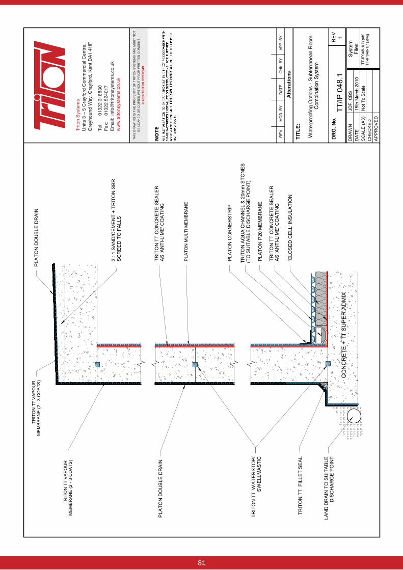
81
Trito
n Sy
stem
sU
nits
3 –
5 C
rayf
ord
Com
mer
cial
Cen
tre,
Gre
yhou
nd W
ay, C
rayf
ord,
Ken
t DA1
4H
F
Tel:
0132
2 31
8830
Fax:
01
322
5240
17Em
ail:
info
@tri
tons
yste
ms.
co.u
kw
ww.
trito
nsys
tem
s.co
.uk
THIS
DR
AWIN
G IS
TH
E PR
OPE
RTY
OF
TRIT
ON
SYS
TEM
S AN
D M
UST
NO
T BE
LO
ANED
OR
CO
PIED
WIT
HO
UT
PRIO
R W
RIT
TEN
CO
NSE
NT
© 2
010
TRIT
ON
SYS
TEM
S
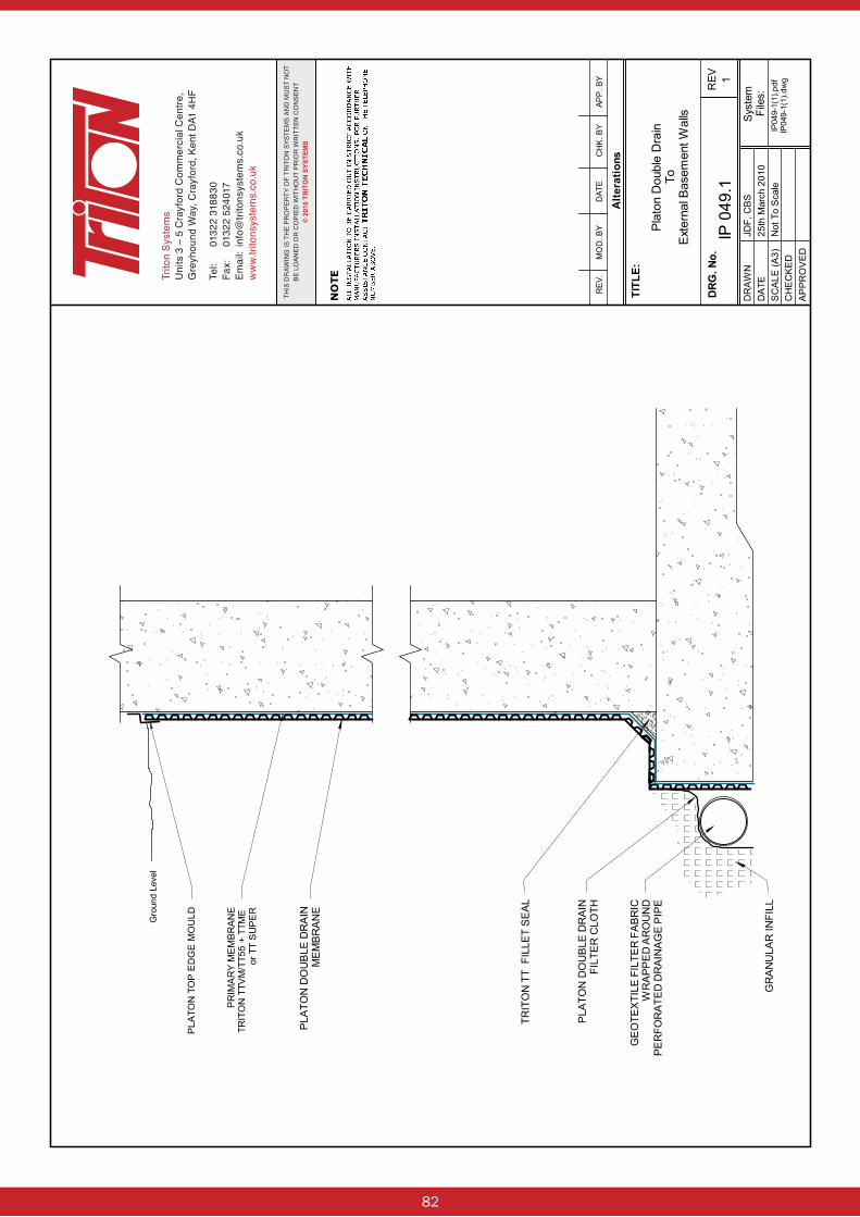
82
Trito
n Sy
stem
sU
nits
3 –
5 C
rayf
ord
Com
mer
cial
Cen
tre,
Gre
yhou
nd W
ay, C
rayf
ord,
Ken
t DA1
4H
F
Tel:
0132
2 31
8830
Fax:
01
322
5240
17Em
ail:
info
@tri
tons
yste
ms.
co.u
kw
ww.
trito
nsys
tem
s.co
.uk
THIS
DR
AWIN
G IS
TH
E PR
OPE
RTY
OF
TRIT
ON
SYS
TEM
S AN
D M
UST
NO
T BE
LO
ANED
OR
CO
PIED
WIT
HO
UT
PRIO
R W
RIT
TEN
CO
NSE
NT
© 2
010
TRIT
ON
SYS
TEM
S
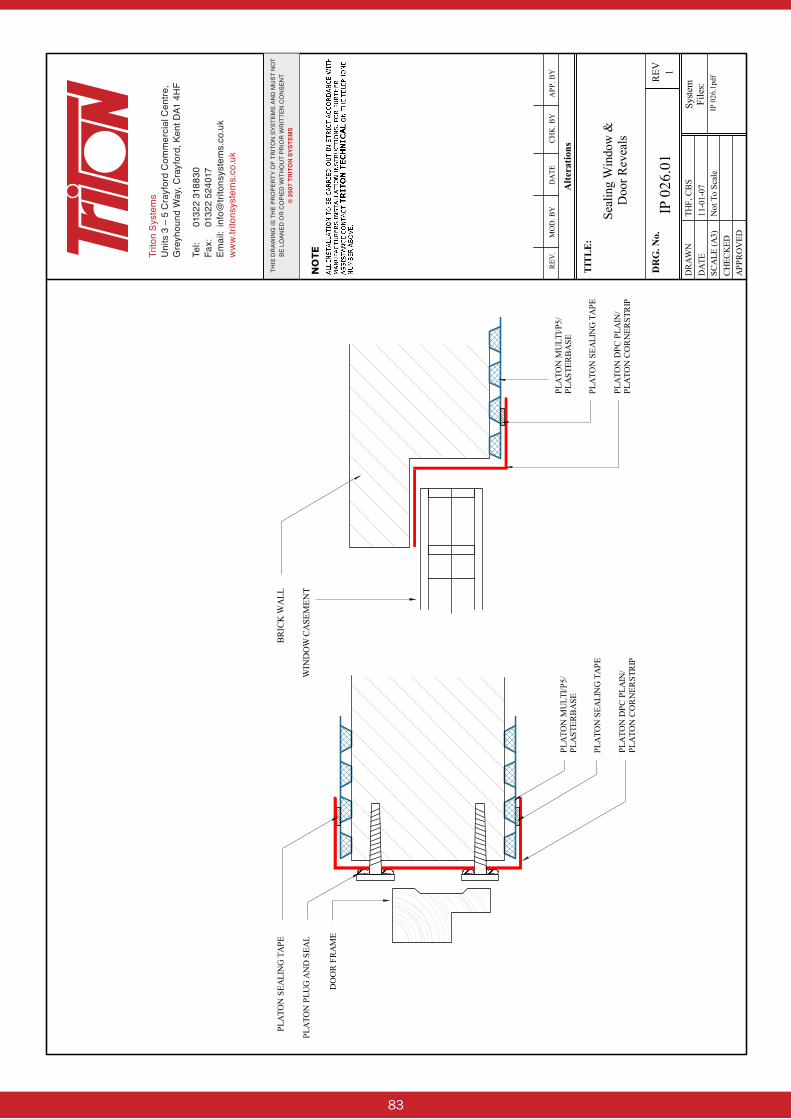
83
Trito
n Sy
stem
sU
nits
3 –
5 C
rayf
ord
Com
mer
cial
Cen
tre,
Gre
yhou
nd W
ay, C
rayf
ord,
Ken
t DA1
4H
F
Tel:
0132
2 31
8830
Fax:
01
322
5240
17Em
ail:
info
@tri
tons
yste
ms.
co.u
kw
ww.
trito
nsys
tem
s.co
.uk
THIS
DR
AWIN
G IS
TH
E PR
OPE
RTY
OF
TRIT
ON
SYS
TEM
S AN
D M
UST
NO
T BE
LO
ANED
OR
CO
PIED
WIT
HO
UT
PRIO
R W
RIT
TEN
CO
NSE
NT
© 2
007
TRIT
ON
SYS
TEM
S

84
Trito
n Sy
stem
sU
nits
3 –
5 C
rayf
ord
Com
mer
cial
Cen
tre,
Gre
yhou
nd W
ay, C
rayf
ord,
Ken
t DA1
4H
F
Tel:
0132
2 31
8830
Fax:
01
322
5240
17Em
ail:
info
@tri
tons
yste
ms.
co.u
kw
ww.
trito
nsys
tem
s.co
.uk
THIS
DR
AWIN
G IS
TH
E PR
OPE
RTY
OF
TRIT
ON
SYS
TEM
S AN
D M
UST
NO
T BE
LO
ANED
OR
CO
PIED
WIT
HO
UT
PRIO
R W
RIT
TEN
CO
NSE
NT
© 2
007
TRIT
ON
SYS
TEM
S
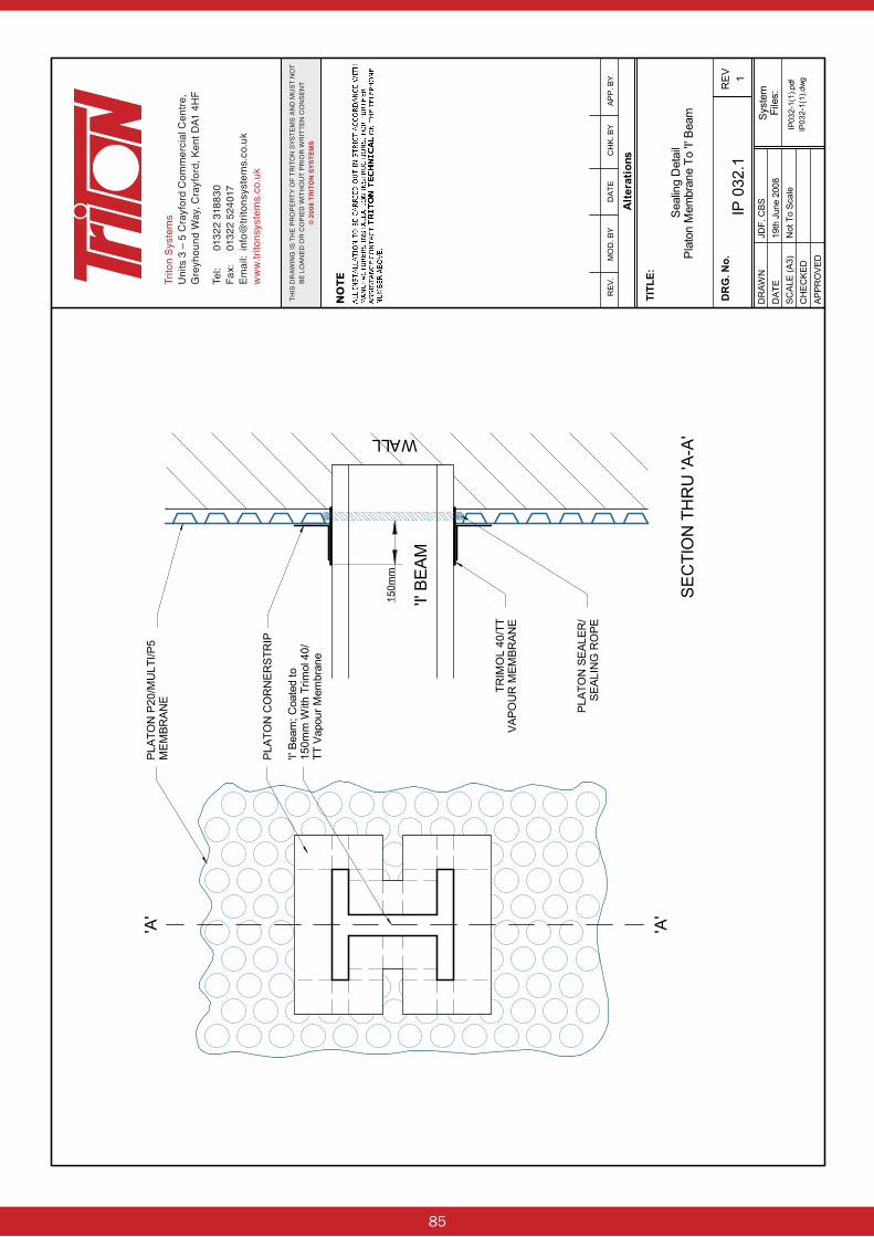
85
Trito
n Sy
stem
sU
nits
3 –
5 C
rayf
ord
Com
mer
cial
Cen
tre,
Gre
yhou
nd W
ay, C
rayf
ord,
Ken
t DA1
4H
F
Tel:
0132
2 31
8830
Fax:
01
322
5240
17Em
ail:
info
@tri
tons
yste
ms.
co.u
kw
ww.
trito
nsys
tem
s.co
.uk
THIS
DR
AWIN
G IS
TH
E PR
OPE
RTY
OF
TRIT
ON
SYS
TEM
S AN
D M
UST
NO
T BE
LO
ANED
OR
CO
PIED
WIT
HO
UT
PRIO
R W
RIT
TEN
CO
NSE
NT
© 2
008
TRIT
ON
SYS
TEM
S
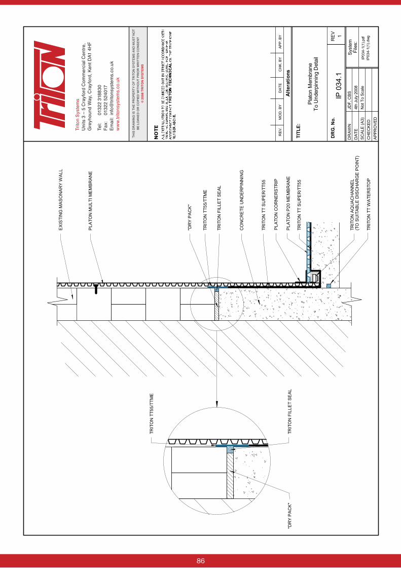
86
Trito
n Sy
stem
sU
nits
3 –
5 C
rayf
ord
Com
mer
cial
Cen
tre,
Gre
yhou
nd W
ay, C
rayf
ord,
Ken
t DA1
4H
F
Tel:
0132
2 31
8830
Fax:
01
322
5240
17Em
ail:
info
@tri
tons
yste
ms.
co.u
kw
ww.
trito
nsys
tem
s.co
.uk
THIS
DR
AWIN
G IS
TH
E PR
OPE
RTY
OF
TRIT
ON
SYS
TEM
S AN
D M
UST
NO
T BE
LO
ANED
OR
CO
PIED
WIT
HO
UT
PRIO
R W
RIT
TEN
CO
NSE
NT
© 2
008
TRIT
ON
SYS
TEM
S