platon cavity drain membrane - uk
TRANSCRIPT
Platon Cavity Drain MembraneINSTALLATION MANUAL
www.tritonsystems.co.uk

3
1391 01/21

3
Contents Page
Isola and Triton – history and background 5
System Platon – an introduction 5
1. General guidance notes on specification and installation 6
2. Membrane installation – internal basement application – Platon P8, Platon P20 9
3. Membrane installation – internal basement application – Platon Plaster Base/Plaster Mesh 14
4. Membrane installation – external basement application – Platon Double Drain 16
5. Triton AquaPump Pro range – product information 17
6. Triton AquaPump Pro range – installation guidelines 18
7. Triton AquaPump Pro range – technical specifications 18
8. Triton AquaPump Pro range – dimensions 26
9. Triton AquaPump Pro range – parts list 26
10. Accessories 26
11. Wiring diagrams 27
12. Transport 27
13. Maintenance 27
14. Triton AquaChannel 27
15. Photographic illustrations 32
16. Typical details 42
16. Sumps and pumps guidance notes 45
18. Pump service schedule 47
19. Pipe service seal detail 49
20. Product specifications 50

4 5

4 5
Isola Platon MembraneTriton Systems
Background/History
Isola is the original inventor of studded membrane (Platon) and was founded in 1940 in Norway. The Isola Group has since grown to become world leaders in the field of cavity drain waterproofing membranes for the construction industry. Isola has produced many millions of square metres of membrane and roofing products worldwide and through their research and development, continues to be at the cutting edge of innovation and technology in this field.
Triton Systems has been historically linked with Isola Platon since 1995 and in 1998 took over the UK and Ireland operations to become the sole distributor and promoter of Isola Platon membranes and components.
Platon cavity membranes, together with Triton’s own extensive range of waterproofing and damp-proofing products and water drainage systems give the specifier and installation contractor the complete basement and below ground waterproofing system, backed by many years of technical and practical experience. This manual is focused on waterproofing, the principles of installation also apply to the Platon membranes when used above ground for damp-proofing purposes, see data sheets for Platon Comfort (floors), PB2 Mesh (damp walls), P20 Floor and DE25.
Isola Platon cavity drain membranes
Platon cavity drain membranes also known as 'System Platon' are made of studded high-density polyethylene (HDPE) and Polypropylene (PP) sheets, which are impervious to water, moisture vapour and Radon gas. When placed against structures the studs form a permanent cavity or air gap between the structure and the internal shell. They can be used internally or externally to drain and manage water and damp ingress (type C as defined in BS8102:2009)
‘System Platon’ is not a tanking method. The term ‘tanking’ originates from the industrial process of lining structures with a waterproof material, which is applied either externally (on the positive side) or internally (on the negative side). Tanking materials such as multi-coat renders, cementitious waterproofing slurries, asphalts and liquid applied bitumen coatings, typically used in existing basements and cellars, rely on either a mechanical or chemical bond directly on to the substrate and act as barriers to the water (type A materials). The majority of these are moisture vapour permeable.
Cavity drain membranes do not add to the structural stress to which the basement walls and floor may be subject to, nor do they influence the movement of the water, unlike the ‘tanking’ materials which can de-bond from weak substrates when hydrostatic pressure comes to bear, or in the case of partial waterproofing, cause the water to migrate to a previously unaffected area. Issues relating to the risk of slab floatation and integrity are also reduced when cavity membranes are used.
In new-build underground structures the cavity membranes (type C) are often used in conjunction with a resistant structure (type B integral protection) such as watertight concrete e.g. TT Admix or an external type A barrier material such as a pre or post-applied membrane e.g. Triton Hydrolock or EX100. Such combined or dual systems are very reliable and help the waterproofing specifier or designer demonstrate that consideration of the guidance laid out in BS8102:2009 has been made.
6 7
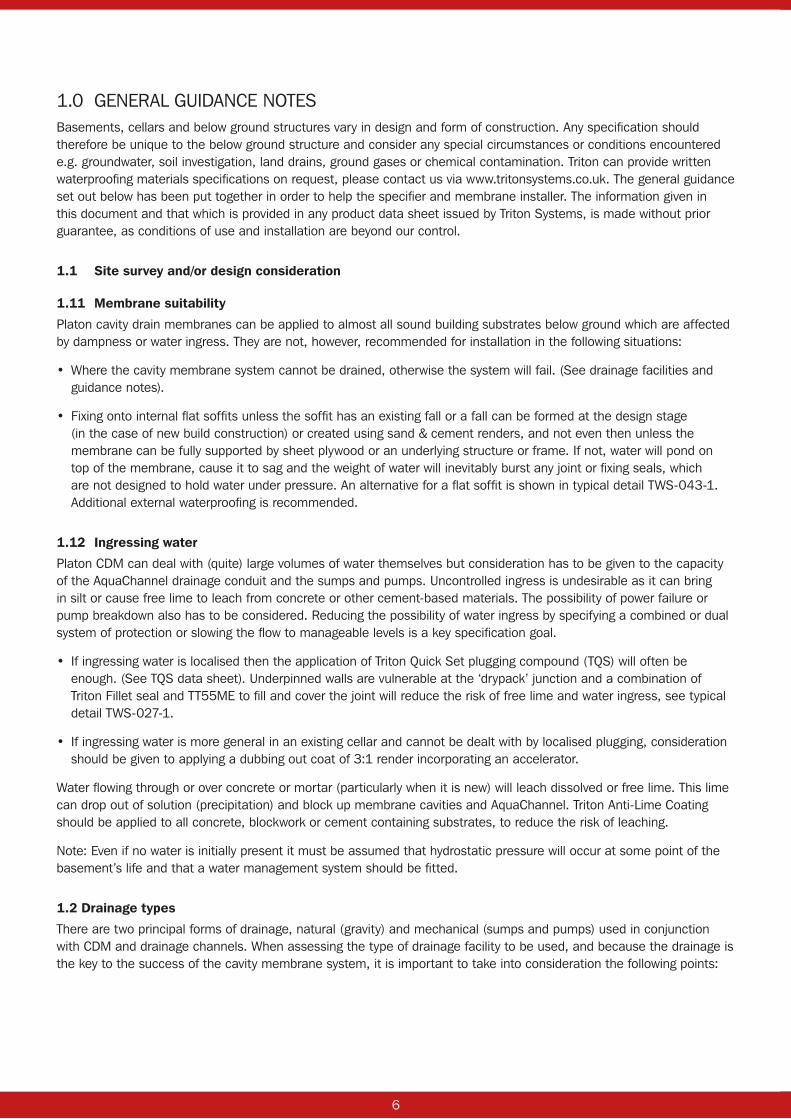
1.0 GENERAL GUIDANCE NOTESBasements, cellars and below ground structures vary in design and form of construction. Any specification should therefore be unique to the below ground structure and consider any special circumstances or conditions encountered e.g. groundwater, soil investigation, land drains, ground gases or chemical contamination. Triton can provide written waterproofing materials specifications on request, please contact us via www.tritonsystems.co.uk. The general guidance set out below has been put together in order to help the specifier and membrane installer. The information given in this document and that which is provided in any product data sheet issued by Triton Systems, is made without prior guarantee, as conditions of use and installation are beyond our control.
1.1 Site survey and/or design consideration
1.11 Membrane suitability
Platon cavity drain membranes can be applied to almost all sound building substrates below ground which are affected by dampness or water ingress. They are not, however, recommended for installation in the following situations:
• Where the cavity membrane system cannot be drained, otherwise the system will fail. (See drainage facilities and guidance notes).
• Fixing onto internal flat soffits unless the soffit has an existing fall or a fall can be formed at the design stage (in the case of new build construction) or created using sand & cement renders, and not even then unless the membrane can be fully supported by sheet plywood or an underlying structure or frame. If not, water will pond on top of the membrane, cause it to sag and the weight of water will inevitably burst any joint or fixing seals, which are not designed to hold water under pressure. An alternative for a flat soffit is shown in typical detail TWS-043-1. Additional external waterproofing is recommended.
1.12 Ingressing water
Platon CDM can deal with (quite) large volumes of water themselves but consideration has to be given to the capacity of the AquaChannel drainage conduit and the sumps and pumps. Uncontrolled ingress is undesirable as it can bring in silt or cause free lime to leach from concrete or other cement-based materials. The possibility of power failure or pump breakdown also has to be considered. Reducing the possibility of water ingress by specifying a combined or dual system of protection or slowing the flow to manageable levels is a key specification goal.
• If ingressing water is localised then the application of Triton Quick Set plugging compound (TQS) will often be enough. (See TQS data sheet). Underpinned walls are vulnerable at the ‘drypack’ junction and a combination of Triton Fillet seal and TT55ME to fill and cover the joint will reduce the risk of free lime and water ingress, see typical detail TWS-027-1.
• If ingressing water is more general in an existing cellar and cannot be dealt with by localised plugging, consideration should be given to applying a dubbing out coat of 3:1 render incorporating an accelerator.
Water flowing through or over concrete or mortar (particularly when it is new) will leach dissolved or free lime. This lime can drop out of solution (precipitation) and block up membrane cavities and AquaChannel. Triton Anti-Lime Coating should be applied to all concrete, blockwork or cement containing substrates, to reduce the risk of leaching.
Note: Even if no water is initially present it must be assumed that hydrostatic pressure will occur at some point of the basement’s life and that a water management system should be fitted.
1.2 Drainage types
There are two principal forms of drainage, natural (gravity) and mechanical (sumps and pumps) used in conjunction with CDM and drainage channels. When assessing the type of drainage facility to be used, and because the drainage is the key to the success of the cavity membrane system, it is important to take into consideration the following points:

6 7
1.21 Natural (combined foul chambers and integral gullies)
Where drainage with gravity is feasible within the bounds of the property or at a point of exit from the property, it is most important to establish that the ‘internal drainage’ is in good working order and how this connects to the public sewer or a soakaway. Drains or soakaways can and do block up and the risk of surcharging should be dealt with by using separate gullies or valves. Discharge to soakaways should be considered for semi-basements only.
In situations where the Platon CDM installer finds that the only possibility of draining the system is into a foul/soakaway drain or his client so instructs, liability for the waterproofing system is excluded in the event of blockage of the foul pipes or the soakaways filling up. Isola and Triton Systems always recommend the inclusion of sump and pumps.
1.22 Mechanical (sump and pump)
Triton Systems supplies a number of sump and pump combinations to suit basement size and depth. The AquaPump Pro and XL Range, which have been specifically designed for the purpose of dealing with ground water ingress, comprises a range of sump kits with single or twin pumps. The sump itself is a moulded polyethylene chamber with a structural galvanized steel lid. The ‘Pro’ kits contain a single Nautilus/301 or 303 pump (according to spec) which is controlled by an integral float switch. The pump is supplied with a non-return valve and the kit includes an Aquasafe ‘mini’ high level water alarm. The AquaPump Pro Plus Kit consists of two pumps in the sump chamber and the Pro BBPS contains a 240v pump and a 24v back-up pump, powered via a battery pack and charger panel. The AquaPump XL is a larger moulded sump chamber suited to commercial or multi-depth basements. Like the ‘Pro’ it is available with 301 or 303 pumps, single or dual, plus high capacity RS55 pumps. Power back-up is provided by Powersafe battery and charger units, which also have an alarm function. Industry best practice is to have two pumps in any sump chamber with at least one of those connected to a reserve power supply. Single pumps are for low risk installations only. Refer to the data sheets and installation guides for each type, for more information. See typical details TWS-061-1 and 060-1 for Pro and XL sump dimensions. Water from lightwells should not be directed back into the basement, to be handled by the sump and pumps unless the area concerned is less than 10sqm or so. Larger areas should have their own, independent pumps or separate drainage.
1.23 Drainage channel (Triton AquaChannel)
Triton also produces AquaChannel, a PVC drainage conduit specifically designed for the collection and management of water ingress in below ground situations. It is fitted around the perimeter of the floor slab at the vulnerable wall/floor junction and is used in conjunction with the Platon cavity drain membrane system. Water entering the building through the walls or across the floor is controlled behind the Platon membrane and diverted to the AquaChannel at the base of the wall, located within a pre-formed recess (100mm wide x 60mm deep) or installed on top of the slab with a 50mm layer of screed, concrete or XPS waterproof insulation forming the spacing zone, the water enters the AquaChannel through pre-drilled drainage holes. AquaChannel is not a gutter, it provides a clear space for water to run rapidly to the sump or gravity drain whilst offering maintainable access via rodding/inspection points. See typical details TWS-022-1, 021-1, 088-1 or 066-1. Sumps should have at least two separate inlets from the AquaChannel run.
1.24 Falls (floors)
It is essential that the floor is flat and level, this also applies to the AquaChannel recess. New or existing floors should be flood tested to ensure that water will drain to the AquaChannel and on to the sump or discharge point, before any cavity membrane is fitted or laid. High or low spots should be ground off or filled as necessary.
IMPORTANT NOTE: As a default position (head height permitting) we recommend that Platon P20 be used on floors. P20 membrane has a far greater drainage capacity and is more tolerant of undulations and out of level substrates than P8, which significantly reduces the risk of hydrostatic pressure building up underneath it, which might threaten joints and overlaps. Any floor membrane should always be used in conjunction with a perimeter drainage conduit such as AquaChannel, correctly recessed or spaced.
8 9
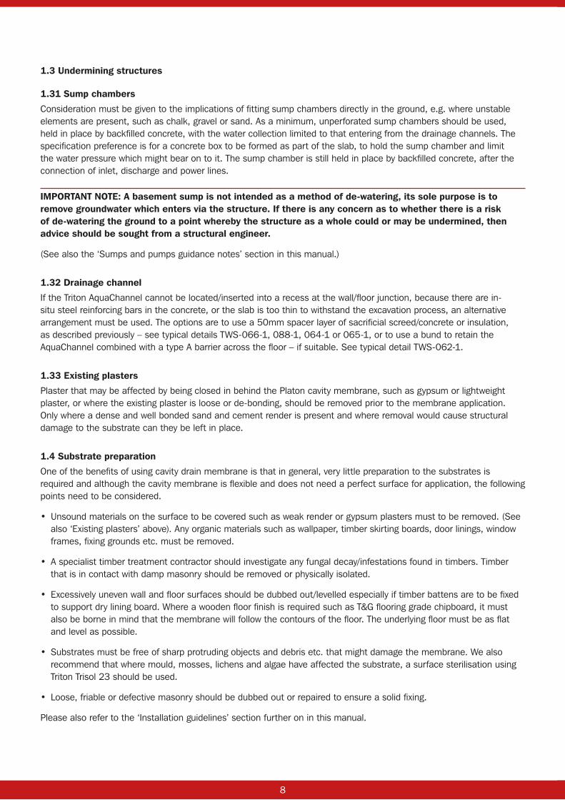
1.3 Undermining structures
1.31 Sump chambers
Consideration must be given to the implications of fitting sump chambers directly in the ground, e.g. where unstable elements are present, such as chalk, gravel or sand. As a minimum, unperforated sump chambers should be used, held in place by backfilled concrete, with the water collection limited to that entering from the drainage channels. The specification preference is for a concrete box to be formed as part of the slab, to hold the sump chamber and limit the water pressure which might bear on to it. The sump chamber is still held in place by backfilled concrete, after the connection of inlet, discharge and power lines.
IMPORTANT NOTE: A basement sump is not intended as a method of de-watering, its sole purpose is to remove groundwater which enters via the structure. If there is any concern as to whether there is a risk of de-watering the ground to a point whereby the structure as a whole could or may be undermined, then advice should be sought from a structural engineer.
(See also the ‘Sumps and pumps guidance notes’ section in this manual.)
1.32 Drainage channel
If the Triton AquaChannel cannot be located/inserted into a recess at the wall/floor junction, because there are in-situ steel reinforcing bars in the concrete, or the slab is too thin to withstand the excavation process, an alternative arrangement must be used. The options are to use a 50mm spacer layer of sacrificial screed/concrete or insulation, as described previously – see typical details TWS-066-1, 088-1, 064-1 or 065-1, or to use a bund to retain the AquaChannel combined with a type A barrier across the floor – if suitable. See typical detail TWS-062-1.
1.33 Existing plasters
Plaster that may be affected by being closed in behind the Platon cavity membrane, such as gypsum or lightweight plaster, or where the existing plaster is loose or de-bonding, should be removed prior to the membrane application. Only where a dense and well bonded sand and cement render is present and where removal would cause structural damage to the substrate can they be left in place.
1.4 Substrate preparation
One of the benefits of using cavity drain membrane is that in general, very little preparation to the substrates is required and although the cavity membrane is flexible and does not need a perfect surface for application, the following points need to be considered.
• Unsound materials on the surface to be covered such as weak render or gypsum plasters must to be removed. (See also ‘Existing plasters’ above). Any organic materials such as wallpaper, timber skirting boards, door linings, window frames, fixing grounds etc. must be removed.
• A specialist timber treatment contractor should investigate any fungal decay/infestations found in timbers. Timber that is in contact with damp masonry should be removed or physically isolated.
• Excessively uneven wall and floor surfaces should be dubbed out/levelled especially if timber battens are to be fixed to support dry lining board. Where a wooden floor finish is required such as T&G flooring grade chipboard, it must also be borne in mind that the membrane will follow the contours of the floor. The underlying floor must be as flat and level as possible.
• Substrates must be free of sharp protruding objects and debris etc. that might damage the membrane. We also recommend that where mould, mosses, lichens and algae have affected the substrate, a surface sterilisation using Triton Trisol 23 should be used.
• Loose, friable or defective masonry should be dubbed out or repaired to ensure a solid fixing.
Please also refer to the ‘Installation guidelines’ section further on in this manual.
8 9
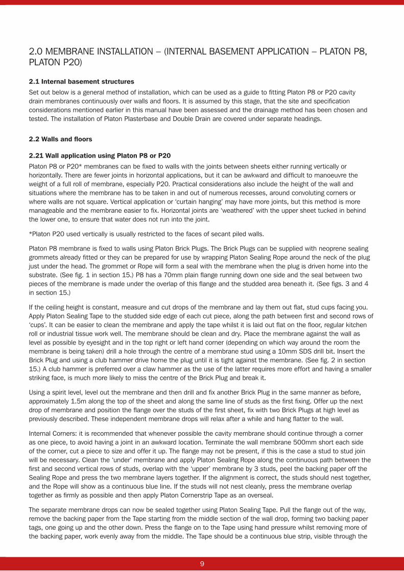
2.0 MEMBRANE INSTALLATION – (INTERNAL BASEMENT APPLICATION – PLATON P8, PLATON P20)
2.1 Internal basement structures
Set out below is a general method of installation, which can be used as a guide to fitting Platon P8 or P20 cavity drain membranes continuously over walls and floors. It is assumed by this stage, that the site and specification considerations mentioned earlier in this manual have been assessed and the drainage method has been chosen and tested. The installation of Platon Plasterbase and Double Drain are covered under separate headings.
2.2 Walls and floors
2.21 Wall application using Platon P8 or P20
Platon P8 or P20* membranes can be fixed to walls with the joints between sheets either running vertically or horizontally. There are fewer joints in horizontal applications, but it can be awkward and difficult to manoeuvre the weight of a full roll of membrane, especially P20. Practical considerations also include the height of the wall and situations where the membrane has to be taken in and out of numerous recesses, around convoluting corners or where walls are not square. Vertical application or ‘curtain hanging’ may have more joints, but this method is more manageable and the membrane easier to fix. Horizontal joints are ‘weathered’ with the upper sheet tucked in behind the lower one, to ensure that water does not run into the joint.
*Platon P20 used vertically is usually restricted to the faces of secant piled walls.
Platon P8 membrane is fixed to walls using Platon Brick Plugs. The Brick Plugs can be supplied with neoprene sealing grommets already fitted or they can be prepared for use by wrapping Platon Sealing Rope around the neck of the plug just under the head. The grommet or Rope will form a seal with the membrane when the plug is driven home into the substrate. (See fig. 1 in section 15.) P8 has a 70mm plain flange running down one side and the seal between two pieces of the membrane is made under the overlap of this flange and the studded area beneath it. (See figs. 3 and 4 in section 15.)
If the ceiling height is constant, measure and cut drops of the membrane and lay them out flat, stud cups facing you. Apply Platon Sealing Tape to the studded side edge of each cut piece, along the path between first and second rows of ‘cups’. It can be easier to clean the membrane and apply the tape whilst it is laid out flat on the floor, regular kitchen roll or industrial tissue work well. The membrane should be clean and dry. Place the membrane against the wall as level as possible by eyesight and in the top right or left hand corner (depending on which way around the room the membrane is being taken) drill a hole through the centre of a membrane stud using a 10mm SDS drill bit. Insert the Brick Plug and using a club hammer drive home the plug until it is tight against the membrane. (See fig. 2 in section 15.) A club hammer is preferred over a claw hammer as the use of the latter requires more effort and having a smaller striking face, is much more likely to miss the centre of the Brick Plug and break it.
Using a spirit level, level out the membrane and then drill and fix another Brick Plug in the same manner as before, approximately 1.5m along the top of the sheet and along the same line of studs as the first fixing. Offer up the next drop of membrane and position the flange over the studs of the first sheet, fix with two Brick Plugs at high level as previously described. These independent membrane drops will relax after a while and hang flatter to the wall.
Internal Corners: it is recommended that whenever possible the cavity membrane should continue through a corner as one piece, to avoid having a joint in an awkward location. Terminate the wall membrane 500mm short each side of the corner, cut a piece to size and offer it up. The flange may not be present, if this is the case a stud to stud join will be necessary. Clean the ‘under’ membrane and apply Platon Sealing Rope along the continuous path between the first and second vertical rows of studs, overlap with the ‘upper’ membrane by 3 studs, peel the backing paper off the Sealing Rope and press the two membrane layers together. If the alignment is correct, the studs should nest together, and the Rope will show as a continuous blue line. If the studs will not nest cleanly, press the membrane overlap together as firmly as possible and then apply Platon Cornerstrip Tape as an overseal.
The separate membrane drops can now be sealed together using Platon Sealing Tape. Pull the flange out of the way, remove the backing paper from the Tape starting from the middle section of the wall drop, forming two backing paper tags, one going up and the other down. Press the flange on to the Tape using hand pressure whilst removing more of the backing paper, work evenly away from the middle. The Tape should be a continuous blue strip, visible through the

10 11
flange overlap. In very cold or humid conditions a heat gun can be very carefully used to obtain a good sealed joint. (See figs. 3 and 4 in section 15.)
The remainder of the Platon Brick Plugs can now be fixed in position, as needed, to accommodate the chosen dry lining system or screw-in wall ties. Up to 5 per square metre are needed.
Fixings: Soft substrates may require a smaller drill bit than the regular 10mm, to ensure that a tight fixing is achieved.
2.22 Floor application using Platon P20
Once the membrane has been fitted to the walls and before any dry lining or other wall finish is installed, the floor membrane should be laid (this may not apply if a blockwork liner wall is to be built – see below). As mentioned earlier in this guide, Platon P20 is recommended for floors unless there is a head height restriction, in which case Platon P8 can be used – with care.
Begin at one side of the room and unroll the Platon P20 up against the wall membrane with the studs facing down onto the floor (cups upward) and cut the membrane to the desired length or width of the floor. Repeat this exercise until all the lengths/widths required to cover the floor area have been cut, allowing for a two-stud membrane overlap. (See fig. 7 in section 15.) The idea is that the overlapping membrane edges will nest together, but sometimes over a very long run the studs fall out of alignment. If this happens the membrane edges can be butted together and Platon Overtape or Cornerstrip can be used to complete the seal.
The overlapping edges are sealed with Platon Sealing Rope. The Sealing Rope is positioned on the path between the first and second rows of cups. In a similar way to the method used when sealing the P8, remove the release paper from the Sealing Rope in the middle of the run. Lift the next sheet of P20 over the two interlocking studs/cups and press the overlapping membrane down onto the Sealing Rope. (See figs. 6, 7 and 8 in section 15.)
Foot pressure can be applied over the membrane joint, to ensure that the overlap is fully bonded. The next stage of the process is to link the P20 to the wall membrane. Fig. 5 in section 15 shows the wall and floor membranes ready to be sealed together.
Platon Cornerstrip is used to seal the floor to wall junction. Cornerstrip is single sided, strong and flexible and is used to seal around pipe penetrations, dpc junctions and soffit terminations etc. The Cornerstrip is folded in half along its length and positioned with the crease pressed into the angle of the floor to wall junction. (See figs. 9 and 10 in section 15.) Once correctly aligned, carefully pull off half the backing paper and press firmly out with the palm of the hand onto the floor membrane. Remove the other half and press the Cornerstrip on to the wall membrane. Internal and external angles can be formed by using a short piece of Cornerstrip, cutting carefully to the crease, before bonding in place. (See figs.11 and 12 in section 15.) Create reinforcing pieces from small lengths of Cornerstrip and fit over the corner. (See figs. 13, 14 and 15 in section 15.) Internal corners are sealed by cutting the Cornerstrip carefully to the crease and turning it in on itself. A small reinforcing piece can be pressed into the bottom apex of the corner if required.
2.23 P20 application when a blockwork liner wall is to be built
There are several ways of dealing with the requirement for an internal blockwork wall, structural or not. Platon P20 has excellent compressive strength and it is in some circumstances possible to build a wall directly off it or the screed layer on top – advice from a structural engineer should be sought. See typical details TWS-022-1, TWS-037-1 and TWS-040-1. In these instances, it is good practice to lay a 500mm wide strip of P20 around the perimeter of the basement, sealed to the wall membrane with Cornerstrip and covered along the inside edge with polythene and masking tape. When the wall has been built the polythene and tape can be removed, revealing a clean and undamaged edge to which the remainder of the P20 can overlap or butt up to, just prior to floor screeding or covering. Enabling works have been allowed to continue without risking damage to the membrane laid over the entire floor.
The alternative is to build the blockwork liner wall off a course of engineering brick or insulating block, just inboard of the AquaChannel, incorporating a strip of high quality DPC linked and sealed to the wall and floor membrane, see typical details TWS-037-1, TWS-067-1 and TWS-088-1. The bricks or blocks are left with open and clean perp joints to allow water to migrate from the floor surface to the AquaChannel. The method is acceptable when the AquaChannel is in a recess or laid on top of the slab.

10 11
2.24 Floor application using Platon P8
Platon P8 should be used over basement or below ground floors with caution. Advice from our Technical Department should be sought. The sub-floor must be very level and flat, any hollows or pockets may trap water which might then build up and come through joints causing a leak.
The installation of P8 across a floor is similar to that for walls: the flange overlap joints are sealed with Platon Sealing Tape or Sealing Rope. Platon Cornerstrip is used to seal the floor and wall membranes together, as above. The membrane is loose laid.
2.25 Flat soffit application using Platon P8
As mentioned earlier in this manual, Platon cavity drain membranes should not be fixed to the underside of a flat soffit unless absolutely necessary and a fall already exists, or one can be created in the soffit itself. In all circumstances a sheet plywood support and timber frame should be placed underneath the membrane to fully support it. Consideration also has to be given to where the drained water will be directed, if it is evident that it will appear above a door or window head, an alternative plan should be conceived. The soffit should be measured to establish the desired lengths or widths of membrane required to cover the area and then a further 200mm of membrane should be added to the measurements, to allow for the membrane to be lapped down all the peripheral walls.
Apply Sealing Rope to the Platon Brick Plugs as previously described. Then around the perimeter edges of the membrane, fold it inward 200mm to form a positive crease and to create a down lap. Offer the membrane up to the soffit and position the down lap creases into the junction between the soffit and wall.
Drill and fix enough Platon Brick Plugs through the membrane and into the soffit to hold the membrane in place with the studs against the soffit.
Offer the next length/sheet of membrane up to the soffit and position the flange over the studs of the first sheet, fix and secure the membrane as described above. Repeat this operation until all the membrane sheets are held in place. Thoroughly clean the flange and the studs where the seal is to be made as previously described for wall application.
Apply Platon Sealing Tape to the stud area under the flange and press the overlap together. The membrane should now be sealed to form one continuous sheet, Platon Brick Plugs can now be fixed through the membrane, in positions to accommodate the chosen dry lining system. Install the wall membrane on the inside of the down laps and seal with Sealing Rope and Cornerstrip.
NOTE: It is important to ensure that the membrane is taut against the soffit, does not sag and is fully supported by plywood and a frame, otherwise water ponding will occur, and the membrane seals could fail.
NOTE: An alternative method for dealing with flat soffits using a combination of Platon membrane to walls and Triton TT55 slurry to soffit can be seen in detail TWS-043-1 on the technical drawing page at www.tritonsystems.co.uk.
2.26 Service entry seals
Where there are service penetrations such as pipes, ducting or steel stanchions that protrude through walls or floors, the membrane should be carefully cut and trimmed around the penetration and sealed using a combination of Platon Cornerstrip, Triton Fillet Seal, TT Swellmastic and TT55ME. (See fig. 16 in section 15 and refer to typical details TWS-047-1, TWS-048-1, TWS 081-1 and TWS-090-1.)
2.27 Doors and windows – existing basements and cellars
Door linings, window frames and timber surrounds should always be removed to enable the Platon membrane to be extended around or into door and window reveals to maintain the continuity of the waterproofing system and to also provide a physical barrier between the frames and damp masonry. In situations where the Platon membrane would restrict or limit the profile of replaced frames, a regular high quality plain DPC, sealed to the Platon with Cornerstrip, can be used to line and protect the reveals instead. See typical detail TWS-052-1.

12 13
2.28 Continuity of waterproofing
Cavity drain membrane systems are often used in conjunction with external type A membranes or coatings. Both should extend up to ground level to meet with the DPC and tray arrangement. How this is done will depend on the form of construction and the materials specified. Our Technical Department can assist with developing an appropriate solution on receipt of plans and drawings.
2.29 Heating, ventilation and de-humidification
There is no requirement to ventilate the cavity behind the membrane or the sump chamber in a fully sealed waterproofing system. BS8102 (2009) Table 2 points out the various environmental grades of waterproofing protection that may be specified. The level of heating, ventilation and de-humidification provided should be appropriate to the intended use of the below ground structure. Condensation should not form on the face of the Platon membrane if these measures are introduced and a vapour control layer is placed behind the plasterboard lining. There is no need to leave a gap between the AquaChannel upstand and the P8 membrane on the wall, it should be sealed with Cornerstrip as illustrated on many of our typical details.
2.30 Wall finishing
Linings can be formed using independent metal ‘fast track’ frame, timber frame, blockwork or batten and board.
If timber battens are to be used, the traditional method is to fix a vertical batten 25mm x 50mm. The brick plugs in this instance should be fixed at 400mm centres horizontally and 600mm centres vertically. The timber batten is fixed to the Platon Brick Plug via the blind screw hole in the head, using a size 10, 1½" long chipboard screw, or 5mm x 35mm.
For a metal fast track dry lining system such as Gypliner or Lafarge which might require stabilizing brackets, the brick plugs should be fixed at 600mm centres horizontally and 800mm centres vertically. If an independent timber or metal frame system is to be used, the wall membrane can be ‘curtain hung’. The membrane is simply dressed vertically down the walls just like hanging a curtain or sheet, fewer Brick Plugs are used, usually just enough to hold the membrane neatly in place. Joints are sealed with Platon Sealing Tape as normal.
If an independent brick/blockwork wall needs to be built in front of the Platon wall membrane and it requires lateral restraint, then Isola Bluebird wall ties can be used. Isola Bluebird wall ties are screwed into the blind screw hole in the head of the Platon Brick Plug and anchored into the mortar bed joint as the wall is built. (See fig. 23 in section 15 or refer to detail TWS-039-1.)
Walls which need to be built abutting the retaining structure can also be stabilized by using the Platon Brick Plugs as grounds for Isola Bluebird wall ties or starter strip. See typical detail TWS-036-1.
2.31 ICF structures
Fixing into ICF (in-situ concrete formwork) is most often made by using Platon Plaster Plugs which are available in a variety of lengths to suit the thickness of the inner skin of the insulated formwork. The concrete wall core is used as a sound substrate for the plugs. Platon Brick Plugs are usually shorter than the thickness of insulation on the inside and do not offer a secure enough fixing in this layer alone, unless they can be fitted through the plastic webbing reinforcement present in some brands of ICF. The use of TT Admix concrete as the filling for the walls is advised as a method of dealing with the risk of free lime leaching.

12 13
2.32 Floor finishes
There is a wide choice of floor coverings that can be laid on top of Platon floor membranes:
Platon P8 (Wood based flooring)
Flooring grade T & G chipboard, parquet, laminate, wood strip
Platon P8 (Sand/cement screeds)
Domestic: Minimum 50mm sand and cement screed. A reinforced polymer modified self-levelling screed can also be used subject to approval by the screed supplier.
Commercial/Industrial: Minimum 75mm reinforced sand and cement screed. A reinforced polymer modified self-levelling screed, subject to the criteria above.
Platon P20 (Wood based flooring)
Flooring grade T & G chipboard, parquet, laminate and wood strip can also be applied, but a T & G chipboard base should be laid first.
Platon P20 (Sand/cement screeds)
Domestic: Minimum 75mm reinforced screed.
Industrial: Minimum 100mm reinforced concrete.
2.33 Insulation
Insulation used to create a spacer layer when AquaChannel is laid direct on a slab must be 50mm thick (minimum), waterproof, closed cell XPS and have a compressive strength in excess of 300 Kpa.
2.34 Curved soffits and vaulted rooms
A conventional vault with curved ceilings allows the water to run off freely, unlike a flat soffit, and the following method can be adopted:
When lining vaults always work from the front to the back, starting along the centre line of the vault. Measure the length of the vault and add 400mm to this measurement, then cut the membrane to length. Form a 900mm downturn, crease 200mm in from both ends of the membrane and prepare the Platon Brick Plugs by wrapping with Platon Sealing Rope as previously described. The neoprene grommets should not be used.
Offer the membrane up to the vault ceiling along the centre line of the vault, and drill and hammer home the fixing plugs in a straight line at 600mm centres from front to rear. These will provide fixing points for the dry lining system. The creased downturn at both ends of the vault will start to deform going into the curvature of the vault ceiling. Where this occurs, carefully slit/cut the deformed sections towards the crease but stop short of the crease by one stud.
The membrane can now be overlaid and will flatten out and follow the curvature. Several careful cuts may be required to achieve this depending on the radius of the vault. Continue to work out from the first sheet, ensuring a weathered joint of not less than eight studs. The flanged edge of the new pieces should be used to make both of the weathered joints either side of the initial membrane strip, fixed off the central line of the vault. The weathered joints are sealed flange over stud using Platon Sealing Tape as previously described. Overseal with Platon Cornerstrip for security.
All the sheets running from front to back of the vaulted cellar are cut to the overall length of the vaulted soffit. This should give coverage to the vault, past the springing line down to the floor slab, together with a 200mm return to both ends of the vault.
The end walls are now ready to be lined with the membrane. The end wall sections are cut to the true width of the vault so that the membrane overlaps the ceiling returns already formed. These sections of membrane are fixed and sealed in exactly the same way as described for wall application. The end wall membrane stud to stud joint should be sealed around the radius with Platon Sealing Rope and oversealed with Platon Cornerstrip. The floor membrane is now ready to be laid over the completed drainage system and is sealed to the wall membrane using Platon Cornerstrip.
Generally, vaulted ceilings should be lined with Platon P8. This limits the number of fixings used, when compared to using Plaster Base or Plaster Mesh, reducing the risk of a poorly secured fixing causing a leak. Batten and board or other dry-lining methods are also lighter and easier to apply and finish than wet renders and plaster.

14 15
3.0 MEMBRANE INSTALLATION - INTERNAL BASEMENT APPLICATION – PLATON PLASTER BASE, PLATON PLASTER MESH
Platon Plaster Base and Platon Plaster Mesh perform similar functions but are moulded and formed differently.
Plaster Base: moulded with shallow, wide studs forming an undercut such that plaster, or dab adhesive becomes physically attached and keyed to the membrane.
Plaster Mesh: has a similar stud profile to Platon P8 but is covered with mesh/net which provides a key for plaster or dab adhesive.
Plaster Base/ Mesh can be applied to new or existing solid wall finishes. All surfaces must be sound and clean. Gypsum plaster, wallpaper, embedded timber or other moisture sensitive materials must be removed. Any voids or hollow areas should be filled or dubbed out level prior to application. Platon Plaster Base/Mesh is for internal use only on walls and curved soffits and is compatible with other Platon membranes. Plaster Base should not be used on floors. Plaster Mesh can be used on floors, with the same provisos as for Platon P8.
Platon Plaster Base/Mesh is fixed to walls with the Platon Plaster Plug, 70mm long is supplied as standard, with 90, 120 and 140mm lengths available. Plaster Plugs should be prepared for use by fitting silicone Plaster Plug Seals or by wrapping Platon Sealing Rope around the neck of the plug, just under the head. This will form a seal with the membrane when the plug is driven home into the substrate.
If the ceiling height is constant, measure and cut drops of the membrane to suit. The membrane should be clean and dry. Place the membrane against the wall as level as possible by eyesight and in the top right or left hand corner (depending on which way around the room the membrane is being taken) drill a hole, 3 studs inboard of the edge, through the centre spacing between 4 studs, not through the studs/cups themselves, using an 8mm SDS drill bit. Insert the Plaster Plug and using a club hammer drive home the plug until it is tight against the membrane. (See fig. 17 in section 15.) A club hammer is preferred over a claw hammer as the use of the latter requires more effort and having a smaller striking face, is much more likely to miss the centre of the Plaster Plug and break it.
Using a spirit level, level out the membrane and then drill and fix another brick plug in the same manner as before, approximately 1.5m along the top of the sheet and along the same line of studs as the first fixing. Offer up the next drop of membrane and position it with an overlap of 2 studs across the first sheet, fix with two Plaster Plugs at high level as previously described. These independent membrane drops will relax after a while and hang flat to the wall.
Internal Corners: it is recommended that whenever possible the cavity membrane should continue through a corner as one piece, to avoid having a joint in an awkward location. Terminate the wall membrane 500mm short each side of the corner.
Down the overlap joint, fix Platon Plaster Plugs through the studs as close as possible to the edge of the overlapping membrane. Fixings should be made at 150mm centres along this joint. Continue fixing the Plaster Plugs through the rest of the membrane in a diamond pattern through the centre spacing between the 4 studs until enough fixings have been installed, a minimum 13/m² are required, this equates to an approximate spacing of 250mm. Alternatively fit the Plugs at 350mm spacings in a square and add the fifth plug in the centre of that square, as on a 5 of dice.
The membrane must fit tightly against the structure with no voids or hollow areas left underneath as this can cause plaster application and bonding problems. Care should also be taken at corners to ensure the membrane is creased and folded tightly into the angle to avoid snagging or tearing with a trowel when plaster is applied.
Once all fixings are in place, clean the membrane surface thoroughly along the overlap joint and ensure it is dry and clean. Apply Platon Overtape along the joint with equal overlaps onto each sheet of membrane and press firmly into place. A Platon floor membrane can now be laid over the completed drainage system.

14 15
3.1 Finishes
Most common lightweight and renovating plasters or sand/cement renders can be applied to Platon Plaster Base/Mesh. (The use of British Gypsum Hardwall or Tuff Coat is not recommended). When using sand/cement render, mixes of 1-part cement to 6-parts washed plastering sand, incorporating either Triton SBR or hydrated lime should be used. Do not use soft or building sand. All render/plasters should be applied in a minimum of two coats, allowing the first coat of 7mm – 10mm to be trowelled firmly into the membrane studs and then lightly scratched to provide a key for subsequent coats to be applied. The first scratch coat should be left to cure and harden. Ideally this should be 7 – 10 days depending on site and atmospheric conditions. The minimum plaster thickness should be 15mm and the maximum thickness (sand/cement: 30mm) (lightweight plasters: 40mm). Plasterboard can also be dot and dabbed onto Plaster Base/Mesh as a fast-track system, using board adhesive.
Plaster dab adhesive should be applied over the fixing plug heads with a total coverage of 50% of the membrane area. Polyurethane foam adhesives, specially formulated for use with plasterboard, can also be used. These have the advantage of a quick setting time, allowing the boards to be skimmed within a few hours of fixing.
Insulated plasterboard cannot be fixed using dab adhesive alone, a mechanical fixing x 2 is a requirement in Building Regulations and as piercings through the membrane would be unsealed, this type of board finish cannot be used with Plaster Base or Plaster Mesh.
3.2 Fixing through Plaster Base/Plaster Mesh after plastering or rendering – above ground only
On occasions where a fixing is required through the membrane, any one of the three fixing methods set out below can be used:
3.21 By using a Platon Brick Plug with Platon Sealing Rope – lightweight fixing only
First mark out on the plaster surface where the fixing is required and then place the head of the brick plug over the mark and draw a pencil line around the circumference of the head. Drill a 10mm hole through the centre and carefully scrape/scratch out the plaster within the pencil line back to expose the membrane. Blow out the debris, insert the brick plug and hammer the plug home so that the head of the plug sits flush with the membrane surface.
3.22 By using a rawl type plug – lightweight fixing only
Simply drill a hole through the plaster and membrane and clean debris from the hole. Fill the hole with Triton Trifix epoxy resin, allowing the resin to ooze out slightly onto the plaster surface, insert the rawl plug, drive in the screw and bracket etc. and allow the Trifix to harden before applying a load.
3.23 By using epoxy adhesive and timber batten – lightweight fixing only
As before, mark out where fixing is required and remove any setting coat plaster. Apply Triton Trifix epoxy resin to the surface area and to the timber batten and press the batten into position. Some temporary support will be required until the Trifix is cured.
3.24 Fixings through cavity membranes generally – below ground before finishes are applied
Heavyweight fixings for plant and equipment, cupboards or other fittings can be made through the Platon cavity membranes by using stainless steel threaded studding bonded in place with Triton Trifix epoxy resin. The holes for the studding should ideally be drilled out before the membrane has been fitted, so that dust and debris can be cleaned out. If this is not possible, the AquaChannel should be thoroughly flushed before the pumps are commissioned. Typical detail TWS-090-1 shows a resin fixing.
16
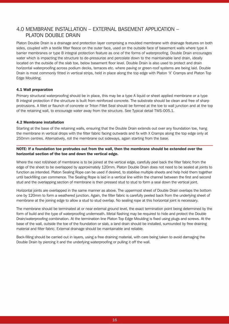
4.0 MEMBRANE INSTALLATION – EXTERNAL BASEMENT APPLICATION – PLATON DOUBLE DRAIN
Platon Double Drain is a drainage and protection layer comprising a moulded membrane with drainage features on both sides, coupled with a textile filter fleece on the outer face, used on the outside face of basement walls where type A barrier membranes or type B integral protection feature as one of the forms of waterproofing. Double Drain encourages water which is impacting the structure to de-pressurize and percolate down to the maintainable land drain, ideally located on the outside of the slab toe, below basement floor level. Double Drain is also used to protect and drain horizontal waterproofing across podium decks, terraces etc. where paving or green-roof systems are being laid. Double Drain is most commonly fitted in vertical strips, held in place along the top edge with Platon ‘X’ Cramps and Platon Top Edge Moulding.
4.1 Wall preparation
Primary structural waterproofing should be in place, this may be a type A liquid or sheet applied membrane or a type B integral protection if the structure is built from reinforced concrete. The substrate should be clean and free of sharp protrusions. A fillet or flaunch of concrete or Triton Fillet Seal should be formed at the toe to wall junction and at the top of the retaining wall, to encourage water away from the structure. See Typical detail TWS-005.1.
4.2 Membrane installation
Starting at the base of the retaining walls, ensuring that the Double Drain extends out over any foundation toe, hang the membrane in vertical drops with the filter fabric facing outwards and fix with X Cramps along the top edge only at 250mm centres. Alternatively, roll the membrane out sideways, again starting from the base.
NOTE: If a foundation toe protrudes out from the wall, then the membrane should be extended over the horizontal section of the toe and down the vertical edge.
Where the next roll/sheet of membrane is to be joined at the vertical edge, carefully peel back the filter fabric from the edge of the sheet to be overlapped by approximately 120mm. Platon Double Drain does not need to be sealed at joints to function as intended. Platon Sealing Rope can be used if desired, to stabilise multiple sheets and help hold them together until backfilling can commence. The Sealing Rope is laid in a vertical line within the channel between the first and second stud and the overlapping section of membrane is then pressed stud to stud to form a seal down the vertical joint.
Horizontal joints are overlapped in the same manner as above. The uppermost sheet of Double Drain overlaps the bottom one by 120mm to form a weathered junction. Again, the filter fabric is carefully peeled back from the underlying sheet of membrane at the joining edge to allow a stud to stud overlap. No sealing rope at this horizontal joint is necessary.
The membrane should be terminated at or near external ground level, the exact termination point being determined by the form of build and the type of waterproofing underneath. Metal flashing may be required to hide and protect the Double Drain/waterproofing combination. At the termination line Platon Top Edge Moulding is fixed using plugs and screws. At the base of the wall, outside the toe of the foundation or slab, a land drain should be installed, surrounded by free draining material and filter fabric. External drainage should be maintainable and reliable.
Back-filling should be carried out in layers, using a free draining material, with care being taken to avoid damaging the Double Drain by piercing it and the underlying waterproofing or pulling it off the wall.

17
5.0 TRITON AQUAPUMP PRO RANGE – PRODUCT INFORMATION
5.1 AquaPump Pro
The AquaPump Pro is specially designed for the removal of groundwater from basement cavity drain membrane systems. The Pro kit comprises a moulded polyethylene tank, locking access cover (pedestrian duty, not suitable for roadways), powerful submersible pump and Aquasafe water level alarm. The system is very versatile, enabling the installer to locate inlets from the AquaChannel drainage conduit through any of the flat sides of the sump chamber, or from above as required. AquaPump Pro is intended for low risk situations such as lightwells. The kit contains a ‘Nautilus’ pump as standard. An AMA 303 high capacity pump can be specified – see data sheet for details.
5.2 AquaPump Pro Plus
The AquaPump Pro Plus is specially designed for the removal of groundwater from basement cavity drain membrane systems. The system comprises a moulded polyethylene tank, locking access cover (pedestrian duty, not suitable for roadways), two powerful submersible pumps and an Aquasafe water level alarm. Two pumps are recommended as minimum for any basement or cellar, the second provides capacity in the event of a breakdown. The kit contains 2 x ‘Nautilus’ pumps as standard. AMA 303 pumps can be specified – see data sheet for details.
5.3 AquaPump Pro BBPS
The AquaPump Pro BBPS is specially designed for the removal of groundwater from basement cavity drain membrane systems. The system comprises a moulded polyethylene tank, locking access cover (pedestrian duty, not suitable for roadways), powerful ‘Nautilus’ submersible pump and a 24V backup pump. The battery and charger box also contain a water level alarm. An AMA 303 pump can be specified – see data sheet for details.
The system comes complete with a battery back-up pump system and is intended as protection where primary pump failure or loss of mains power would be catastrophic. The system acts as a back-up that will alert the end user if the water rises above the normal operating level within the tank and will activate the 24V back-up pump. The system is designed to activate via three separate float switches.
5.4 AquaPump XL
AquaPump XL sump chambers and pump kits are also available. These larger sumps are intended for use in commercial or multi-depth domestic basements and are available with a range of high capacity pump and power back-up options, refer to the Technical Data Sheets for information or speak to our Technical Department.
Please refer to individual product data sheets for information relating to pump capacity and options.

18 19
6.0 TRITON AQUAPUMP PRO RANGE – INSTALLATION GUIDELINESIt is important to note that these instructions are for guidance only and it is the contractor’s responsibility to satisfy themselves that the installation procedure is in accordance with the site conditions and good building practice, to eliminate any potential damage to the system either during or after installation.
The installer should also satisfy themselves that the system can be installed in line with these guidelines, prior to work commencing.
The sump tank is manufactured from polyethylene and as such is extremely robust. However, as with any preformed tank it can be susceptible to floatation and hydrostatic pressure exerted in high water table conditions. Sump tanks should always be backfilled with concrete and if possible, housed within a separate concrete box formed through the floor slab.
Please read these instructions in full prior to commencement of the installation. If you are unsure on any point, then please contact our Technical Department before proceeding.
1. Connection of the internal discharge pipe work within the tank is as follows:
AquaPump Pro (AA/2274) (Single Pump Configuration, Pipekit A supplied as standard)
Fittings kit comes with the following as standard:
No. Qty Description1 1 PVC 1¼" Tank Connector (supplied with the sump tank)2 1 PVC 1¼" Socket Union (supplied as part of Pipekit A, AA/2226T)3 1 PVC 1¼" Male Threaded Adaptor (supplied as part of Pipekit A)4 1 PVC 1¼" Elbow (supplied as part of Pipekit A)5 1 PVC 1¼" Class E Pressure Pipe 0.5 metres (supplied as part of Pipekit A)6 1 32mm Female Threaded Adaptor (supplied with the sump tank)
First select a suitable location for the pump ensuring that the float arm is not obstructed by the tank wall, inlets etc. at its optimum reach. Remove the nut located in the pump switch and push the float arm into place ensuring that the nut is securely replaced. Prior to installing the internal pipe work, check the Non-Return Valve is securely fixed to the pump outlet and ensure that the flap opens in the direction of the pumped flow.
Screw the Male Threaded Adaptor (3) into the Non-Return Valve located on the pump outlet, fit the rest of the pipe kit ensuring that all joints are secure.

18 19
For connection of the external pipe work you will be left with a 1¼" male thread on the outside of the tank, we recommend that you use 1¼" Class E PVC Pressure Pipe but should the installer wish to use 32mm Solvent Weld Waste Pipe (white) then a 32mm Female Threaded Adaptor (6) is supplied within the fittings kit which should be threaded onto the male thread on the outside of the tank. Cut holes in the side of the sump tank to accommodate inlets from the AquaChannel run, also remember to thread power and alarm cables back out to the surface.
AquaPump Pro Plus (AA/2275) (Twin Pump Configuration ‘Twin Discharge’, supplied with Pipekit A and Pipekit C).
Fittings kit comes with the following as standard:
No. Qty Description1 2 PVC 1¼" Tank Connector (supplied with the sump tank)2 2 PVC 1¼" Socket Union (supplied with Pipekit A, AA/2226T and Pipekit C, AA/2222T)3 2 PVC 1¼" Male Threaded Adaptor (supplied with Pipekit A & C)4 2 PVC 1¼" Elbow (supplied with Pipekit A & C)5 2 PVC 1¼" Class E Pressure Pipe 0.5 metres (supplied with Pipekit A & C)6 2 32mm Female Threaded Adaptor (supplied with the sump tank)
Select a suitable location for the pumps ensuring that one pump is positioned on the base of the sump tank and the other on the raised section. It is essential to position the pumps such that the float arms are not obstructed by each other, the tank wall, inlets etc. at their optimum reach (see diagram above). Remove the nut located in the pump switch and push the float arm into place ensuring that the nut is securely replaced. Prior to installing the internal pipe work please check the Non-Return Valves are securely fixed to the pump outlets and ensure that the flap opens in the direction of the pumped flow.
Screw the Male Threaded Adaptor (3) into the Non-Return Valve located on the pump outlet, fit the rest of the pipe kit ensuring that all joints are secure.
For connection of the external pipe work you will be left with a 1¼" male thread on the outside of the tank, we recommend that you use 1¼" Class E PVC Pressure Pipe but should the installer wish to use 32mm Solvent Weld Waste Pipe (white) then a 32mm Female Threaded Adaptor (6) is supplied within the fittings kit which should be threaded onto the male thread on the outside of the tank. Cut holes in the side of the sump tank to accommodate inlets from the AquaChannel run, also remember to thread power and alarm cables back out to the surface.

20 21
Aqua Pump Pro BBPS (AA/2232) (BBPS Pump Configuration ‘BBPS Discharge’, supplied with Pipekit A and Pipekit E).
Fittings kit comes with the following as standard:
No. Qty Description1 2 PVC 1¼" Tank Connector (supplied with the sump tank)2 2 PVC 1¼" Socket Union (supplied with Pipekit A, AA/2226T and Pipekit E, AA/2224T)3 2 PVC 1¼" Male Threaded Adaptor (supplied with Pipekit A & C)4 3 PVC 1¼" Elbow (supplied with Pipekit A & C)5 2 PVC 1¼" Class E Pressure Pipe 0.5 metres (supplied with Pipekit A & C)6 2 32mm Female Threaded Adaptor (supplied with the sump tank)7 3 PVC 1¼" Pl/Th Barrel Nipple (supplied with Pipekit E)
Primary pump pipe work guidelines
Position the primary pump on the base of the tank ensuring that the float arm is not obstructed by the tank wall, inlets etc., at its optimum reach. Remove the nut located in the pump switch and push the float arm into place ensuring that the nut is securely replaced. Prior to installing the internal pipe work check the Non-Return Valve is securely fixed to the pump outlet and ensure that the flap opens in the direction of the pumped flow.
Screw the Male Threaded Adaptor (3) into the Non-Return Valve located on the pump outlet, fit the rest of the pipe kit ensuring that all joints are secure.
For connection of the external pipe work you will be left with a 1¼" male thread on the outside of the tank, we recommend that you use 1¼" Class E PVC Pressure Pipe but should the installer wish to use 32mm Solvent Weld Waste Pipe (white) then a 32mm Female Threaded Adaptor (6) is supplied within the fittings kit which should be threaded onto the male thread on the outside of the tank. Cut holes in the side of the sump tank to accommodate inlets from the AquaChannel run, also remember to thread power and alarm cables back out to the surface.

20 21
BBPS pump and pipework guidelines
Position the 24V pump on the upper part of the sump tank base, fit the brass non-return valve and the rest of the items from Pipekit E.
AquaPump XL
The AquaPump XL is a larger sump tank for commercial and large domestic basements. The principles of installation of both the chamber itself and the pumps, using pre-assembled Pipekits are the same as for the Pro range. AquaPump XL kits are not supplied with an alarm as standard, the POWERSAFE battery back-up unit, recommended as an option with all XL installations acts as a water level alarm via a mini float switch.
AMA 301 and 303 pumps use 1¼" pipe fittings whilst the RS55 high capacity pumps use 2" fittings.
Pipekit A 1¼" Single Pump = AA/2226TPipekit B 1¼” Twin Pump, single discharge = AA/2226TPipekit C 1¼" Twin Pump, twin discharge = AA/2265T Pipekit A 2" Single Pump = AA/2267TPipekit B 2" Twin Pump, single discharge = AA/2280TPipekit C 2" Twin Pump, twin discharge = AA/2268T
TWO Pipekits are required for each installation, always a Pipekit A combined with a B or C.
POWERSAFE
The POWERSAFE unit is available in three versions capable of running 301, 303 or RS55 pumps. One pump only is connected to each unit. The POWERSAFE unit provides battery back-up and alarm functions. Each version is available with four different battery reserve capacities equating to 1, 2, 3 and 4 hours of continuous pumping in the event of mains power failure. As pumps usually only operate a few times an hour, for 2-3 minutes, or less, the power reserves will provide security for several days in most circumstances. If water ingress occurs regularly the 3- or 4-hour units should be specified.
POWERSAFE 900.S for 301 pumps.
POWERSAFE 1300.S for 303 pumps
POWERSAFE 1700.S for RS55 pumps
1hr = AA/37004 1hr = AA/37008 1hr = AA/37012
2hr = AA/37005 2hr = AA/37009 2hr = AA/37013
3hr = AA/37006 3hr = AA/37010 3hr = AA/37014
4hr = AA/37007 4hr = AA/37011 4hr = AA/37015
Sump tank fitting generally
Where the sump chamber is fitted will be dictated by access for ease of maintenance, proximity of a suitable discharge point to limit the distance that water has to be pumped and the difference in levels throughout the basement – the sump has to be located in the lowest part.
1. In all instances the sump tank MUST be positioned on a flat, level concrete base large enough to fully support it. Lay clean, compacted hardcore to the base of the excavation, 100mm thick. Pour mass concrete to a minimum thickness of 150mm, appropriate to the ground conditions.
Carefully position the tank onto the WET concrete base ensuring that no loose debris gets under the tank. Push the tank into the wet concrete by 50mm and add more until the ‘waisted’ moulding at the base of the tank is completely covered. Position the tank so that the inlet, outlet, and cable duct pipe work is all correctly aligned and at the right level. Ballast the tank with water or heavy weights until the concrete is set.
2. Once the tank is positioned connect the inlets (x 2 as a minimum) and discharge pipework and the cable duct. Use a hole saw and rubber grommets to ensure that the pipes are tightly sealed through the tank body.

22 23
3. It is recommended that an external 1¼" gate valve (see section 10.0 Accessories) is installed on the discharge line should the vertical head exceed 3 metres or the discharge line is connected to a foul water outlet.
4. The electrical cables should be now drawn through the cable duct back to the electrical source via a 50mm rubber grommet (fitting not supplied as standard, see section 10.0 Accessories).
5. In all applications the tank must be backfilled with concrete a minimum of 150mm thick. The sump tank should be ballasted with water during backfilling, to resist floatation pressure.
6. The alternative to the above in new build projects or where a new slab is being cast, is to form a reinforced concrete box within the floor to house the sump tank. This reduces the risk of water pressure bearing on the tank and means that the sump etc. can be fitted at a much later date allowing final adjustments to levels to be made. The sump tank is backfilled with concrete after all of the connections have been made. The internal dimensions of the reinforced box are usually 300mm wider in total than the tank and 150mm or so deeper.
7. When pouring the concrete backfill, take care to prevent the concrete entering the tank and any incoming/discharge pipe work.
8. Where groundwater is present in the excavation, local de-watering of the ground must be undertaken during the installation procedure and until the backfill has cured. Please note that the ballast water should not be removed until the backfill has fully set.
9. It is extremely important that once the tank has been installed and all of the connections made, before the pump(s) are installed, the entire system is flushed through and all sand, silt, rubble and general debris removed from the tank. FAILURE TO DO THIS WILL INVALIDATE THE WARRANTY ON THE PUMP(S).
6.1. Electrical connection
A qualified electrician should connect the pump(s) and panels to the mains supply taking into account the electrical information provided here and in the other relevant installation guides.
1. Each 240V pump, BBPS panel or Powersafe should be connected to a 230V 5A (pumps) or 13A (panels and Powersafe) unswitched fused spur connected directly to the distribution board and its own rcd.
2. Ensure that there is suitable slack on the cable to allow for the pump(s) to be removed for maintenance.
6.2. Battery Back-Up Pump System
6.2.1 Electrical connections
A qualified electrician should connect the BBPS panel to the mains supply taking into account the electrical information provided here and in the other relevant installation guides.
1. Select a suitable location for the control panel which must be located within 5m of the sump. The panel should be located somewhere accessible for maintenance purposes and where the water level or power alarms can be heard.
2. Mount the panel to a wall or backboard using the fixing points at the back of the panel using screws and wall plugs (not supplied).
3. The three float switches need to be fixed to the metal tank bracket using the fittings provided (plastic washer and nut). Fix the float switches into position ensuring that the activation arm is dropped downward.
22 23
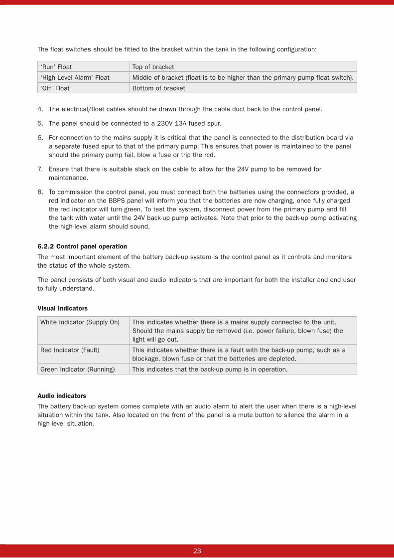
The float switches should be fitted to the bracket within the tank in the following configuration:
‘Run’ Float Top of bracket
‘High Level Alarm’ Float Middle of bracket (float is to be higher than the primary pump float switch).
‘Off’ Float Bottom of bracket
4. The electrical/float cables should be drawn through the cable duct back to the control panel.
5. The panel should be connected to a 230V 13A fused spur.
6. For connection to the mains supply it is critical that the panel is connected to the distribution board via a separate fused spur to that of the primary pump. This ensures that power is maintained to the panel should the primary pump fail, blow a fuse or trip the rcd.
7. Ensure that there is suitable slack on the cable to allow for the 24V pump to be removed for maintenance.
8. To commission the control panel, you must connect both the batteries using the connectors provided, a red indicator on the BBPS panel will inform you that the batteries are now charging, once fully charged the red indicator will turn green. To test the system, disconnect power from the primary pump and fill the tank with water until the 24V back-up pump activates. Note that prior to the back-up pump activating the high-level alarm should sound.
6.2.2 Control panel operation
The most important element of the battery back-up system is the control panel as it controls and monitors the status of the whole system.
The panel consists of both visual and audio indicators that are important for both the installer and end user to fully understand.
Visual Indicators
White Indicator (Supply On) This indicates whether there is a mains supply connected to the unit. Should the mains supply be removed (i.e. power failure, blown fuse) the light will go out.
Red Indicator (Fault) This indicates whether there is a fault with the back-up pump, such as a blockage, blown fuse or that the batteries are depleted.
Green Indicator (Running) This indicates that the back-up pump is in operation.
Audio indicators
The battery back-up system comes complete with an audio alarm to alert the user when there is a high-level situation within the tank. Also located on the front of the panel is a mute button to silence the alarm in a high-level situation.
24 25
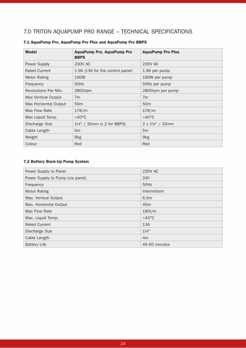
7.0 TRITON AQUAPUMP PRO RANGE – TECHNICAL SPECIFICATIONS
7.1 AquaPump Pro, AquaPump Pro Plus and AquaPump Pro BBPS
Model AquaPump Pro, AquaPump Pro BBPS
AquaPump Pro Plus
Power Supply 230V AC 230V AC
Rated Current 1.9A (13A for the control panel) 1.9A per pump
Motor Rating 190W 190W per pump
Frequency 50Hz 50Hz per pump
Revolutions Per Min. 2800rpm 2800rpm per pump
Max Vertical Output 7m 7m
Max Horizontal Output 50m 50m
Max Flow Rate 174l/m 174l/m
Max Liquid Temp. <40°C <40°C
Discharge Size 1¼" / 32mm (x 2 for BBPS) 2 x 1¼" / 32mm
Cable Length 5m 5m
Weight 9kg 9kg
Colour Red Red
7.2 Battery Back-Up Pump System
Power Supply to Panel 230V AC
Power Supply to Pump (via panel) 24V
Frequency 50Hz
Motor Rating Intermittent
Max. Vertical Output 6.5m
Max. Horizontal Output 45m
Max Flow Rate 180l/m
Max. Liquid Temp. <40°C
Rated Current 13A
Discharge Size 1¼"
Cable Length 4m
Battery Life 45-60 minutes

24 25
8.0 TRITON AQUAPUMP PRO RANGE – DIMENSIONS
8.1 AquaPump Pro, AquaPump Pro Plus and AquaPump Pro BBPS
Diameter 550mm
Height 600mm
8.2 Battery Back-Up Panel
Height 380mm
Width 300mm
Depth 180mm
9.0 TRITON AQUAPUMP PRO RANGE – PARTS LIST
9.1 AquaPump Pro, AquaPump Pro Plus & AquaPump Pro BBPS
Product Name AquaPump Pro & AquaPump Pro BBPS
(Qty)
AquaPump Pro Plus (Qty)
Tank c/w internal float bracket and tank connectors 1 1
Galv Steel Access Cover, Locking, Solid Top 350 x 350mm (Pedestrian Duty)
1 1
Pump (‘Nautilus’ as standard) 1 2
Float Arm for Pump 1 2
Fittings Kit (Pipe work/Fittings) 1(Pro), 2(BBPS) 1
Non-return Valve (integral) 1(Pro), BBPS has brass nrv
2
9.2 Battery Back-Up Pump System
Qty Product Name
3 Mini Float Switch (AA/23020)
1 Control Panel
1 Non-return valve (Brass)
1 24V Back-Up Pump
10.0 TRITON AQUAPUMP PRO RANGE – ACCESSORIES
Product Name Product Code
High Level alarm (Mains Operated) AA/22070T
1¼" Brass Gate Valve AA/10003
110mm Rubber Seal (Drainage Inlet) AA/17010
50mm Rubber Seal (Inlet/Cable Duct) AA/17012
Access Cover, Recessed 450 x 450mm AA/18011

26 27
11.0 TRITON AQUAPUMP PRO RANGE – WIRING DIAGRAMSWiring Diagrams can be found within the control panels and product specific installation guides at www.tritonsystems.co.uk. Should you require further assistance please contact our Technical Department.
12.0 TRITON AQUAPUMP PRO RANGE – TRANSPORTThe pumps are shipped disconnected from the pipe work and fittings to avoid damage in transit. Carefully unpack the items from packaging and inspect for any signs of damage. Should there be missing items or damage please report it immediately (no claim will be considered unless reported within 24 hours of delivery).
13.0 TRITON AQUAPUMP PRO RANGE – MAINTENANCEThe system requires minimal maintenance; however, it should be inspected and cleaned after the first 6 months and then at least annually after that.
The pumps should be run by lifting the float switch and by filling the sump with water. Note the rate at which the water is pumped away. Check the non-return valve for debris, a build-up of silt or lime can cause the valve to jam closed.
Inspect the inlets from the AquaChannel conduit, looking for signs of lime build-up and evidence that water has been draining through. If lime build-up is extensive, the AquaChannel system should be investigated and flushed as necessary.
Check that the water level alarm functions and that it has power. The Aquasafe unit has a ‘service’ light which offers a useful reminder that an inspection is due.
It is advised that the operation of the battery back-up system is checked every 6 months; this can be done by removing the power supply to the primary pump and filling the tank with water until the back-up pump activates. It is also advised that every 6 months the system is allowed to operate using only the back-up pump, this is to allow the batteries to run down and fully recharge which will help to extend their life.
Please note that we recommend that the batteries be replaced every 2 years.
Specialist installing contractors will offer maintenance contracts to carry out an annual inspection, test and clean.

26 27
14.0 TRITON AQUACHANNEL
Description
Triton Aquachannel is used in conjunction with Platon cavity drain membranes to provide a reliable and maintainable drainage system as part of an internal waterproofing specification. Triton Aquachannel is usually located at the base of earth retaining basement or below ground walls, at the edge of the floor slab, to collect and manage away water which might come in from above, through the wall or via the potentially vulnerable wall to floor junction. Triton Aquachannel is moulded from PVC to make an enclosed conduit which allows water to move freely and which is maintainable over the long-term.
Triton Aquachannel is not a ‘gutter’ but provides a clear space for water to flow through, connecting directly to sump and pumps or via outlets running from Universal Channel Outlets/Drain Finials or End Outlets (110mm or 50mm). The water enters through 19mm holes in the angled rear face.
Usage
Triton Aquachannel can be used in new-build, conversion or renovation projects. Triton Aquachannel is usually placed within a pre-formed recess in the ground-bearing slab or on top of it in conjunction with a layer (50mm min) of sacrificial screed or XPS waterproof insulation. It can also be retained inside a bund – itself sealed with TT55/LPA waterproof slurry coating or TT Vapour Membrane.
TWS-066-1(D)

28 29
System Components
Aquachannel Conduit: 2m long with upstand – 80mm wide by 50mm high – 105mm to top of upstand. Also available with no upstand.
Aquachannel Corner: A smooth 90° bend, fully swept, corner connector that ensures water flows easily and smoothly.
Aquachannel ‘T’: An in-line connector piece that allows the main run of Aquachannel to connect at right angles to a secondary ‘arm’ of cross-floor Aquachannel.
Aquachannel In-line Inspection Port: 170mm long channel connector with a moulded opening which accepts 50mm solvent weld ABS waste pipe which can be configured with commonly available elbows, bends and end caps to custom form inspection ports.
Aquachannel Connector: Quick and simple joining together of sections.
Aquachannel Drain Finial: Connects to 110mm ‘pop-up’ pipework running directly to a sump
Aquachannel End Outlet: Connects 50mm solvent weld ABS pipework to the end of an Aquachannel run.
THIS DRAWING IS THE PROPERTY OF TRITON SYSTEMS AND MUST NOT
BE LOANED OR COPIED WITHOUT PRIOR WRITTEN CONSENT
© 2015 TRITON SYSTEMS
Units 3 - 5 Crayford Commercial CentreGreyhound Way, Crayford, Kent. DA1 4HF
Email:Web:
01322 31883001322 524017
Telephone:Fax:
Triton Systemswww.tritonsystems.co.uk
APP. BYCHK. BYDATEMOD. BY
DRAWNDATE
CHECKEDAPPROVED
TITLE:
DRG. No. REV2
SCALE (A3) TWS-022-1(C).pdfTWS-022-1(C).dwg
TWS-022-1(C)
Not To Scale
JDF, CBS, TGL4th May 2018
SystemFiles:
AlterationsREV.
NOTEALL INSTALLATION TO BE CARRIED OUT IN STRICT ACCORDANCE WITHMANUFACTURERS INSTALLATION INSTRUCTIONS. FOR FURTHERASSISTANCE CONTACT TRITON TECHNICAL ON THE TELEPHONENUMBER ABOVE.
OPTION: INCORPORATE TRITON TT ADMIX IN THE CONCRETE TOOBTAIN A COMBINED WATERPROOFING SYSTEM, BOTH FULLY COVEREDBY BBA CERTIFICATION.
4 : 1 SCREED MIX AND LEFT FOR 24 HRSPRIOR TO COMMENCING BLOCKWORK
PLATON P20 MEMBRANEWITH CONCRETE SCREEDOVER
Typical Basement PerimeterWall / Slab Junction With Recess
RC CONCRETE
PLATON P8 MEMBRANE
RC
CO
NC
RET
E
BLANK ACCESS PLATE / SOCKET
TRITON AQUA CHANNEL
67mmMin. H
EIG
HT
VAR
IES
REF
ER T
O A
RC
H. D
RAW
ING
S
PLATON CORNERSTRIP
TRITON TT WATERSTOP/TT SWELLMASTIC
100mm60
mm
TRITON ANTI LIME COATING
75.00mmSCREED
INSULATION
70mm Min
KICKER HEIGHT 150mm
TWS-022-1(C)
28 29
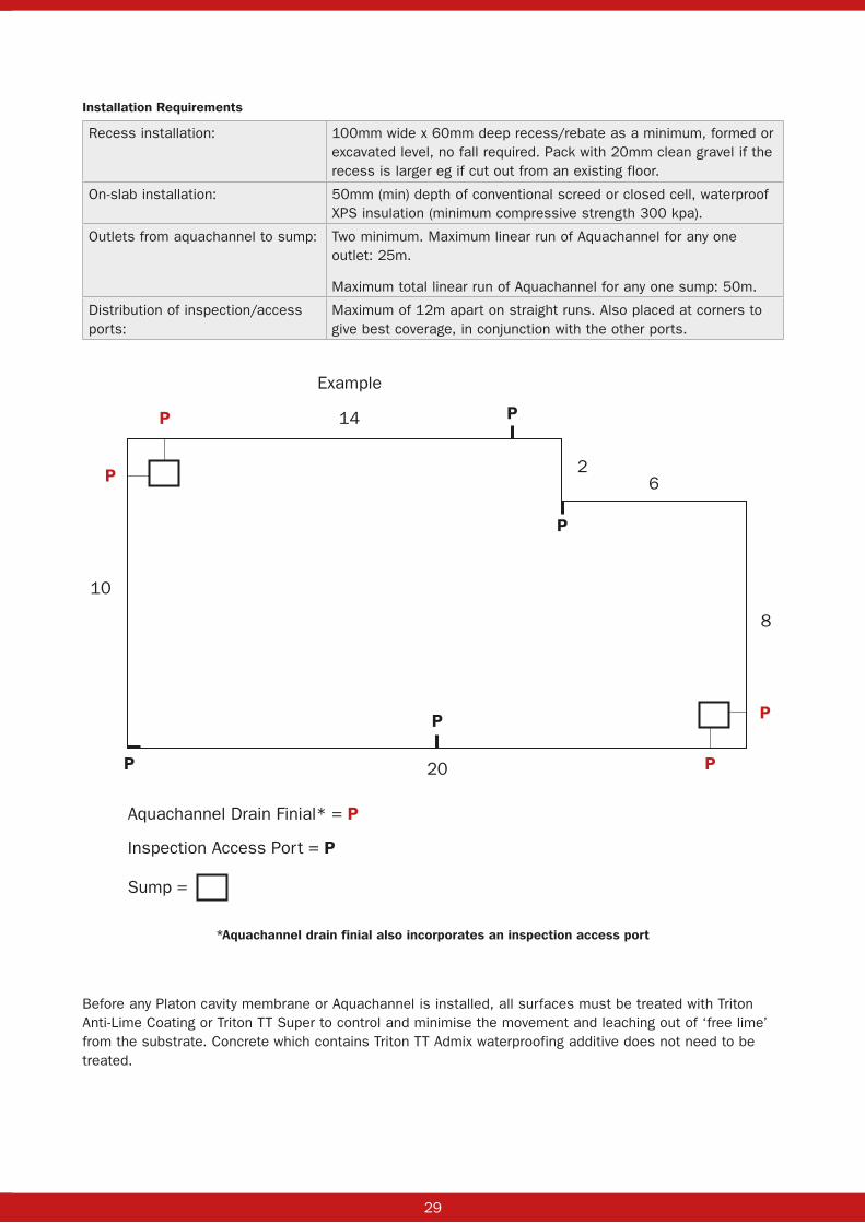
Installation Requirements
Recess installation: 100mm wide x 60mm deep recess/rebate as a minimum, formed or excavated level, no fall required. Pack with 20mm clean gravel if the recess is larger eg if cut out from an existing floor.
On-slab installation: 50mm (min) depth of conventional screed or closed cell, waterproof XPS insulation (minimum compressive strength 300 kpa).
Outlets from aquachannel to sump: Two minimum. Maximum linear run of Aquachannel for any one outlet: 25m.
Maximum total linear run of Aquachannel for any one sump: 50m.
Distribution of inspection/access ports:
Maximum of 12m apart on straight runs. Also placed at corners to give best coverage, in conjunction with the other ports.
P
P
P
P
P
14
20
26
8
10
Aquachannel Drain Finial* = P
Inspection Access Port = P
Example
P
PP
Sump =
*Aquachannel drain finial also incorporates an inspection access port
Before any Platon cavity membrane or Aquachannel is installed, all surfaces must be treated with Triton Anti-Lime Coating or Triton TT Super to control and minimise the movement and leaching out of ‘free lime’ from the substrate. Concrete which contains Triton TT Admix waterproofing additive does not need to be treated.
30 31
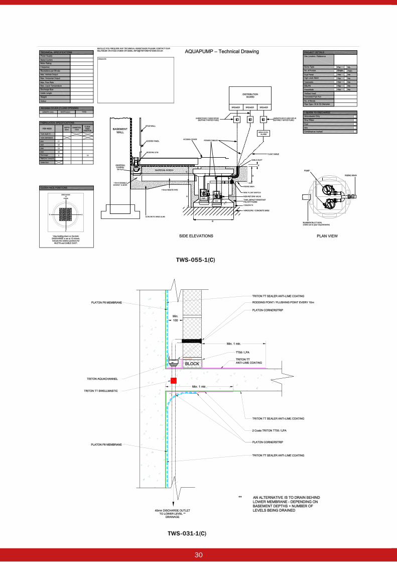
TWS-055-1(C)
TWS-031-1(C)
30 31
Triton Aquachannel is used in conjunction with Platon cavity drain membranes to create maintainable internal waterproofing systems (Type C, as described in BS 8102: 2009) which can be used in conjunction with other forms of waterproofing protection to produce combined or dual waterproofing systems. This might include, for example, Triton TT Admix in the reinforced concrete structure (Type B) or Triton TWS-EX100 sheet membrane (Type A).
These combined systems reduce the risk and consequences of failure, again as laid out in BS 8102: 2009 and are recognised by building warranty providers such as NHBC, Premier, LABC, etc. as being the minimum option.
Technical Assistance
Triton provides product specification services, on-site assistance and product training. Technical staff are CSSW qualified. Visit www.tritonsystems.co.uk to access a full range of data sheets, installation guides, typical drawing details and BBA certificates etc.
Related Products
■ Platon cavity drain membranes: P8, P20, Plaster Mesh, Plaster Base etc. ■ Aqua Pump Pro and XL Sumps and Pumps. ■ Triton TT55 and Triton TT Vapour Membrane coatings.
32 33
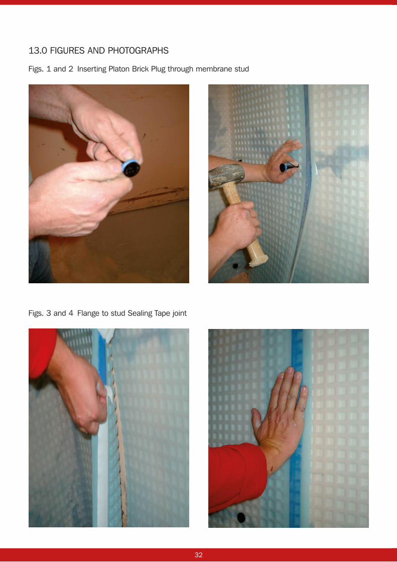
Figs. 3 and 4 Flange to stud Sealing Tape joint
Figs. 1 and 2 Inserting Platon Brick Plug through membrane stud
13.0 FIGURES AND PHOTOGRAPHS

32 33
Fig. 5 Platon P20 floor membrane cut around perimeter walls
Fig. 6 Positioning of Sealing Rope between two studs of the P20 membrane

34 35
Fig. 8 Pressing membranes together to ensure bond
Fig. 7 Positioning membrane stud to stud over Sealing Rope seal

34 35
Fig. 10 Cornerstrip with crease offered into angle
Fig. 9 Forming 90° angle crease in Cornerstrip
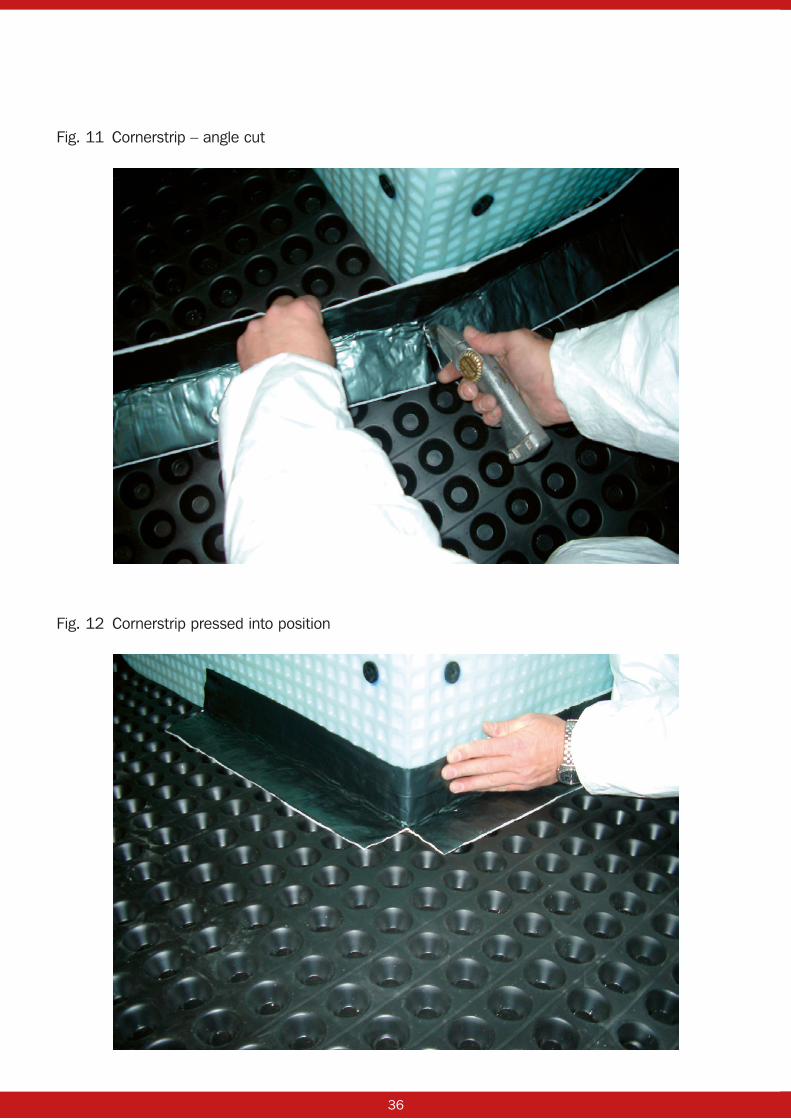
36 37
Fig. 12 Cornerstrip pressed into position
Fig. 11 Cornerstrip – angle cut

36 37
Figs. 13 and 14 Angle piece to seal and complete corner joint

38 39
Fig. 15 Completed Cornerstrip wall/floor junction detail
Fig. 16 Cornerstrip seal to service pipe ducts penetrating through wall structure and membrane.
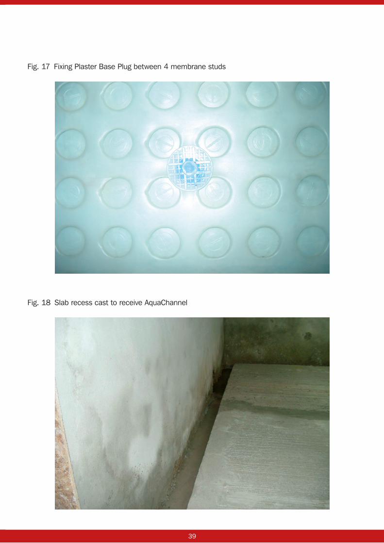
38 39
Fig. 17 Fixing Plaster Base Plug between 4 membrane studs
Fig. 18 Slab recess cast to receive AquaChannel
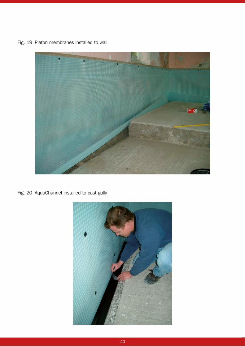
40 41
Fig. 19 Platon membranes installed to wall
Fig. 20 AquaChannel installed to cast gully

40 41
Fig. 21 Infilling to AquaChannel and gully with aggregate(Most AquaChannel installations will not require any aggregate if a 100mm x 60mm recess is formed)
Fig. 22 AquaChannel installation including inspection port

42 43
Fig. 23 Isola Bluebird screw tie – TWS-039-1
16. TYPICAL DETAILS
Bluebird fixing tie to be used inconjunction with System Platon
Isola / Bluebird fixing tie
Platon Sealing Rope
Platon P8
Platon Brick Plug
Wall construction

42 43
Fig. 24 AquaChannel in recess with P8, P20 and TT Admix concrete – TWS-089-1
Fig. 25 Heavyweight resin fixing through P8 membrane – TWS-090-1
4 : 1 screed mix and left for 24 hrsprior to commencing blockwork
RC concrete + Triton TT Admix
Platon P8 membrane
RC
con
cret
e +
Trito
n TT
Adm
ix
Blank access plate / socket
Triton AquaChannel
67mmMin. H
eigh
t va
ries
refe
r to
arc
h. d
raw
ings
Platon Cornerstrip
Triton TT Waterstop/TT Swellmastic
100mm
60m
m
70mm Min
Kicker height 150mm
Platon P20 membranewith concrete screed over
75.00mmscreed
Insulation
2 coats Triton TT55-ME
Triton TT Admix W.T.C
Triton Trifix Epoxy Anchor
Fixing boltBolt fixings toavoid reinforcement
in concrete
150mm
150mm
Platon P8 membrane
Platon Cornerstrip

44
Fig. 26 AquaChannel on slab with XPS Insulation as spacer – TWS-066-1
Fig. 27 Underpin sealing – TWS-027-1
Platon Brick Plug & Seal
Platon P8 membrane
Platon P20 membrane
‘Closed Cell’ insulation
Platon Cornerstop
Triton AquaChannel and 20mm stones(to suitable discharge point)
Triton TT Super 0.75Kg/m²or Triton ‘anti-lime’ coating
TT Admix W.T.C.
TT Admix W.T.C.
Triton TT Waterstop / Swellmastic
Reinforced concrete slab
Triton TT Super 0.75Kg/m²or Triton ‘anti-lime’ coating
Existing masonary wall
Platon P8 Membrane
Platon P20 Membrane
“Dry Pack”
“Dry Pack” Triton Fillet Seal
Triton TT55/TTME
Triton TT55/TTME
Triton TT Super/TT55
Triton TT Super/TT55
Triton TT Waterstop
Triton AquaChannel(to suitable discharge point)
Platon Cornerstrip
Triton Fillet Seal
Concrete underpinning

45
17.0 SUMPS AND PUMPS GUIDANCE NOTES.
Introduction:In most cases when installing a Platon cavity drain system the actual or potential volume and rate of water ingress is not known.
1. Pump capacity:
If the rate and volume of water ingress is known, then the required minimum capacity of the sump and pump system can be easily calculated. Each pump should be able to deal with the expected volume and rate of ingress on its own and not be assisted by the second pump. The capacity of the sump pump is affected by a number of factors and these need to be taken into account when calculating the capacity of your pump system, these include:
1 Internal diameter of discharge pipe. 2 Length of discharge pipe. 3 Head height (including depth of sump chamber). 4 Number of bends / angles in discharge pipe. 5 Stated capacity of pump.
Each of the above WILL affect the capacity of the installed pump, friction losses and head height are critical factors to be considered. Triton Systems has produced a friction loss guide and pump curves, showing the performance at various head heights. Contact the Technical Department for details.
Required capacity can also be calculated. Property Care Association Guidance Note: ‘Groundwater pumping stations serving type C waterproofing systems’, details the methods that can be used to calculate flow rates. This is based on seepage values of 0.1 litres/s per 100m² of basement floor and wall area for basements above the water table and 0.2 litres/s per 100m² of basement wall and floor area for basements below the water table. Allow a safety factor of 5 when selecting a pump duty. For example, a 300m² basement all above the water table would need a pump duty of 1.5 litres per second. The performance curve for the selected pump will show the maximum head that a pump rate of 1.5 litres per second could be achieved.
2. Number of sumps:
The number of sumps required will again vary depending on the volume and rate of water ingress known or anticipated within the system, the size of the floor area being covered and the number of storeys below ground. In general, there should be at least one sump per 50 linear metres of AquaChannel or for every 150 m² floor area.
3. Number of pumps:
Industry best practice advises that two pumps should ALWAYS be used in any one sump chamber as a risk reduction strategy.
Each pump should be capable of handling the expected water volume and flow independently of the other, even the power back-up pump.
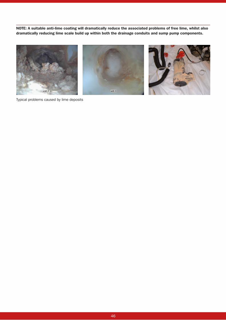
46
NOTE: A suitable anti-lime coating will dramatically reduce the associated problems of free lime, whilst also dramatically reducing lime scale build up within both the drainage conduits and sump pump components.
Typical problems caused by lime deposits
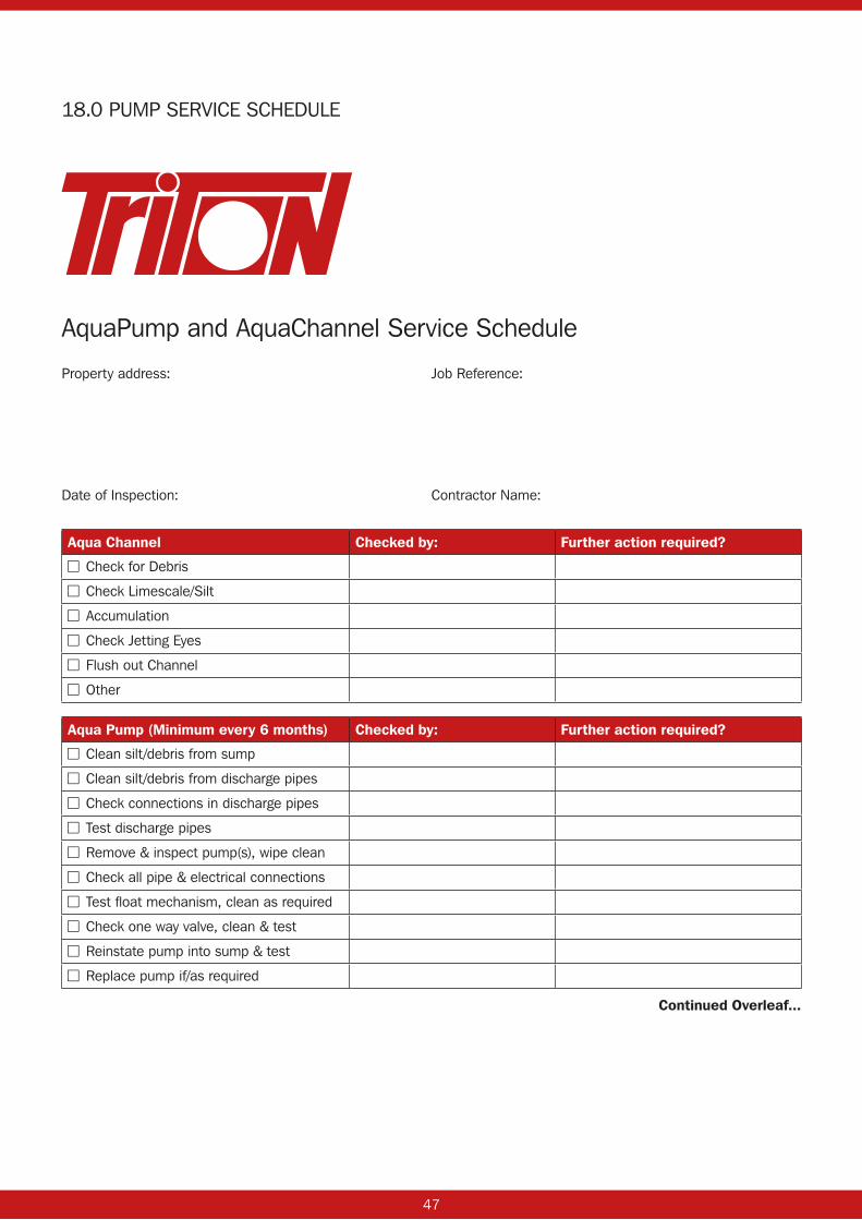
47
AquaPump and AquaChannel Service Schedule
Property address: Job Reference:
Date of Inspection: Contractor Name:
Aqua Channel Checked by: Further action required?
■■ Check for Debris
■■ Check Limescale/Silt
■■ Accumulation
■■ Check Jetting Eyes
■■ Flush out Channel
■■ Other
Aqua Pump (Minimum every 6 months) Checked by: Further action required?
■■ Clean silt/debris from sump
■■ Clean silt/debris from discharge pipes
■■ Check connections in discharge pipes
■■ Test discharge pipes
■■ Remove & inspect pump(s), wipe clean
■■ Check all pipe & electrical connections
■■ Test float mechanism, clean as required
■■ Check one way valve, clean & test
■■ Reinstate pump into sump & test
■■ Replace pump if/as required
Continued Overleaf...
18.0 PUMP SERVICE SCHEDULE
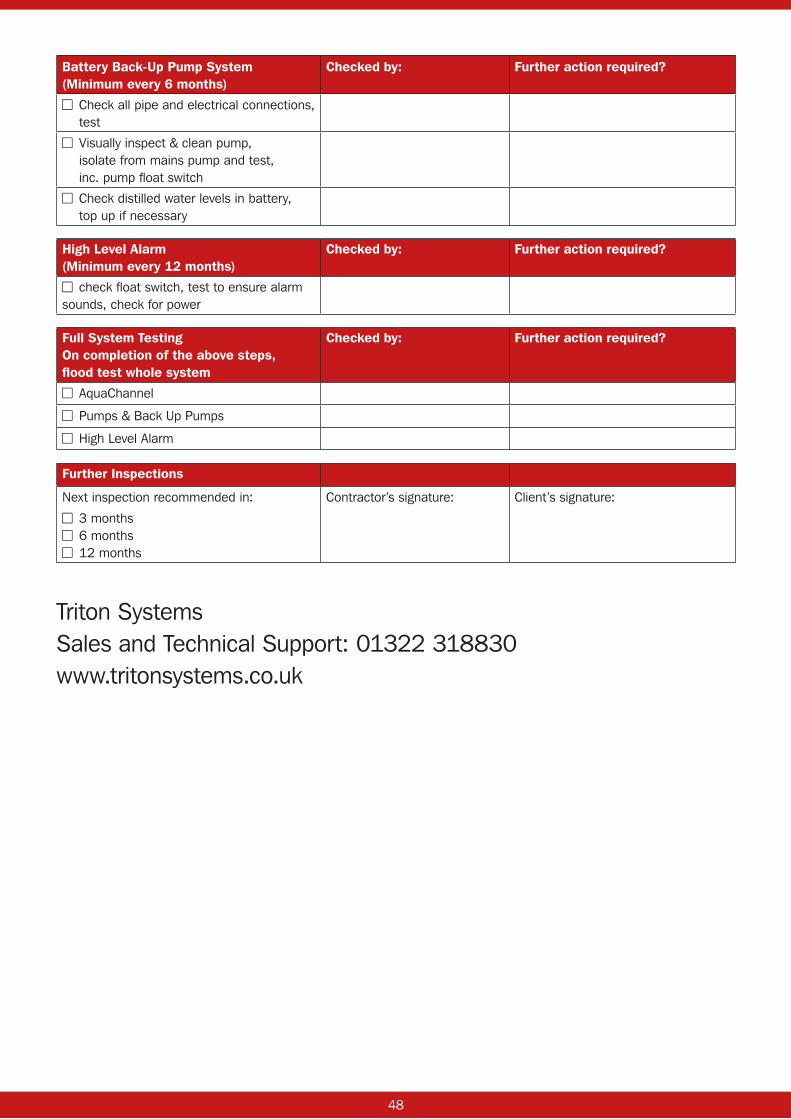
48
Battery Back-Up Pump System (Minimum every 6 months)
Checked by: Further action required?
■■ Check all pipe and electrical connections, test
■■ Visually inspect & clean pump, isolate from mains pump and test, inc. pump float switch
■■ Check distilled water levels in battery, top up if necessary
High Level Alarm (Minimum every 12 months)
Checked by: Further action required?
■■ check float switch, test to ensure alarm sounds, check for power
Full System Testing On completion of the above steps, flood test whole system
Checked by: Further action required?
■■ AquaChannel
■■ Pumps & Back Up Pumps
■■ High Level Alarm
Further Inspections
Next inspection recommended in:
■■ 3 months■■ 6 months■■ 12 months
Contractor’s signature: Client’s signature:
Triton SystemsSales and Technical Support: 01322 318830www.tritonsystems.co.uk

49
19.0 PIPE SERVICE SEAL DETAIL – HORIZONTAL SERVICE ENTRIES THROUGH WALLSPlaton Flextitett can be used to seal service entries where access is available to slot it over the item. This should be sealed using Sealing Rope around base, Sealing Tape between the Flextitett and the membrane and then overtaped with Cornerstrip.
50 51
20.0 SYSTEM PLATON PRODUCT SPECIFICATIONS
Isola Platon cavity drain membranes:
• Platon P8
• Platon P20
• Platon Plaster Base
• Platon Plaster Mesh
• Platon Double Drain
Isola Platon fixing and sealing components:
• Platon Brick Plug (with or without pre-applied seals)
• Platon Plaster Plug
• Platon X-Cramps
• Platon Sealing Rope
• Platon Sealing Tape
• Platon Overtape
• Platon Cornerstrip
• Wall Ties
Triton drainage products:
• Triton AquaPump Pro (sump, lockable cover, mains powered pump)
• Triton AquaPump Pro Plus (sump, lockable cover, two mains powered pumps)
• Triton AquaPump Pro BBPS (sump, lockable cover, mains powered pump, 24V back up pump, control panel)
• Triton AquaPump XL Range (for where greater water ingress is expected – choice of single or dual pump configuration, choice of pump type, choice of auto or manual versions)
• Triton AquaChannel (peripheral drainage conduit with range of accessories)
• Triton Anti-Lime Coating (treatment for concrete and cement materials).
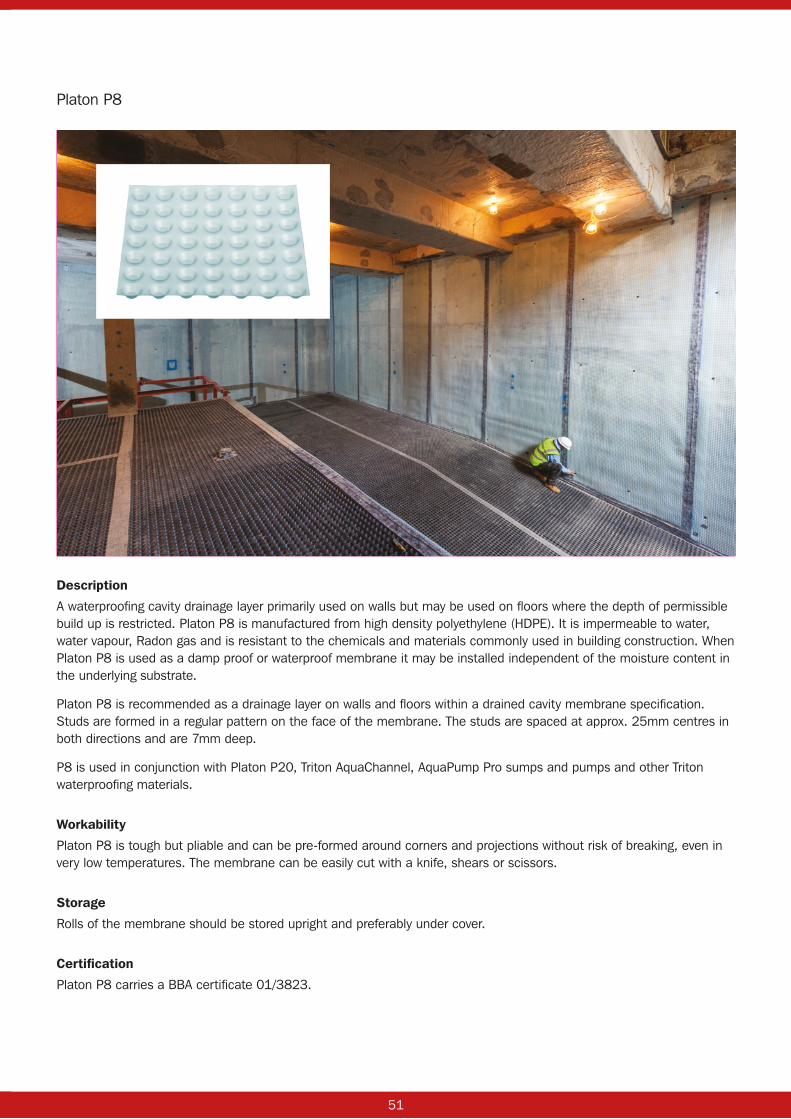
50 51
Description
A waterproofing cavity drainage layer primarily used on walls but may be used on floors where the depth of permissible build up is restricted. Platon P8 is manufactured from high density polyethylene (HDPE). It is impermeable to water, water vapour, Radon gas and is resistant to the chemicals and materials commonly used in building construction. When Platon P8 is used as a damp proof or waterproof membrane it may be installed independent of the moisture content in the underlying substrate.
Platon P8 is recommended as a drainage layer on walls and floors within a drained cavity membrane specification. Studs are formed in a regular pattern on the face of the membrane. The studs are spaced at approx. 25mm centres in both directions and are 7mm deep.
P8 is used in conjunction with Platon P20, Triton AquaChannel, AquaPump Pro sumps and pumps and other Triton waterproofing materials.
Workability
Platon P8 is tough but pliable and can be pre-formed around corners and projections without risk of breaking, even in very low temperatures. The membrane can be easily cut with a knife, shears or scissors.
Storage
Rolls of the membrane should be stored upright and preferably under cover.
Certification
Platon P8 carries a BBA certificate 01/3823.
Platon P8
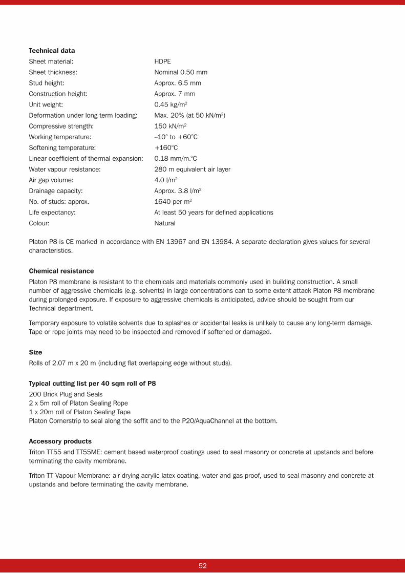
52 53
Technical data
Sheet material: HDPE
Sheet thickness: Nominal 0.50 mm
Stud height: Approx. 6.5 mm
Construction height: Approx. 7 mm
Unit weight: 0.45 kg/m2
Deformation under long term loading: Max. 20% (at 50 kN/m2)
Compressive strength: 150 kN/m²
Working temperature: –10° to +60°C
Softening temperature: +160°C
Linear coefficient of thermal expansion: 0.18 mm/m.°C
Water vapour resistance: 280 m equivalent air layer
Air gap volume: 4.0 l/m2
Drainage capacity: Approx. 3.8 l/m2
No. of studs: approx. 1640 per m2
Life expectancy: At least 50 years for defined applications
Colour: Natural
Platon P8 is CE marked in accordance with EN 13967 and EN 13984. A separate declaration gives values for several characteristics.
Chemical resistance
Platon P8 membrane is resistant to the chemicals and materials commonly used in building construction. A small number of aggressive chemicals (e.g. solvents) in large concentrations can to some extent attack Platon P8 membrane during prolonged exposure. If exposure to aggressive chemicals is anticipated, advice should be sought from our Technical department.
Temporary exposure to volatile solvents due to splashes or accidental leaks is unlikely to cause any long-term damage. Tape or rope joints may need to be inspected and removed if softened or damaged.
Size
Rolls of 2.07 m x 20 m (including flat overlapping edge without studs).
Typical cutting list per 40 sqm roll of P8
200 Brick Plug and Seals2 x 5m roll of Platon Sealing Rope1 x 20m roll of Platon Sealing TapePlaton Cornerstrip to seal along the soffit and to the P20/AquaChannel at the bottom.
Accessory products
Triton TT55 and TT55ME: cement based waterproof coatings used to seal masonry or concrete at upstands and before terminating the cavity membrane.
Triton TT Vapour Membrane: air drying acrylic latex coating, water and gas proof, used to seal masonry and concrete at upstands and before terminating the cavity membrane.

52 53
Description
A waterproofing drainage layer primarily for use over floors and against steel sheet or secant piling within a cavity drain membrane specification. Platon P20 is manufactured from black high-density polyethylene (HDPE). It is impermeable to water, water vapour, Radon gas and is resistant to the chemicals and materials commonly used in building construction. When P20 is used as a damp-proof or waterproof membrane it may be installed independent of the moisture content in the underlying concrete construction. Any water running over the substrate has de-pressurized into the air gap under the membrane.
Studs are formed in a regular pattern on the one face of the membrane. The studs are spaced at approximately 60mm centres and are 20mm deep.
High capacity P20 is recommended for use on all floor applications below ground due to its ability to deal with and isolate running water. The deep stud profile is designed to provide a large water capacity per square metre and thus resist potential blockages caused by lime deposits, (Triton Anti-Lime Coating or Triton TT Super must be used as a dressing on concrete or concrete filled blockwork).
Workability
Platon P20 is tough but pliable and can be formed around corners and projections without risk of breaking even in very low temperatures. The membrane can be easily cut with a knife, shears or scissors.
Storage
Sheets of Platon P20 should be stored flat and rolls of P20 should be stored upright.
Certification
Platon P20 carries a BBA certificate 01/3823.
Platon P20
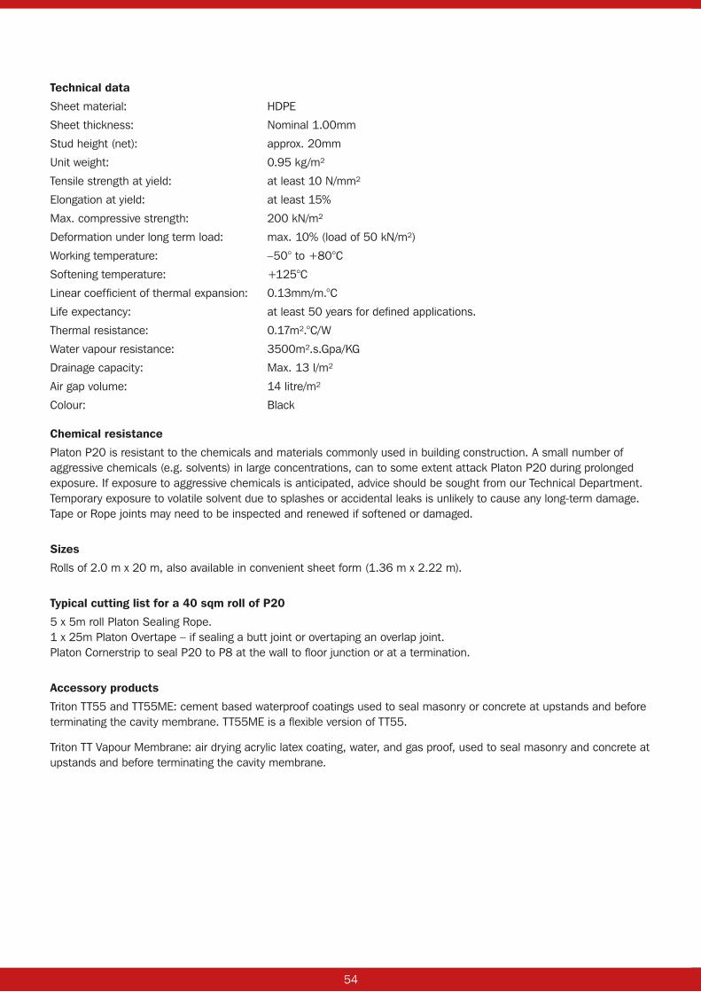
54 55
Technical data
Sheet material: HDPE
Sheet thickness: Nominal 1.00mm
Stud height (net): approx. 20mm
Unit weight: 0.95 kg/m²
Tensile strength at yield: at least 10 N/mm²
Elongation at yield: at least 15%
Max. compressive strength: 200 kN/m²
Deformation under long term load: max. 10% (load of 50 kN/m²)
Working temperature: –50° to +80°C
Softening temperature: +125°C
Linear coefficient of thermal expansion: 0.13mm/m.°C
Life expectancy: at least 50 years for defined applications.
Thermal resistance: 0.17m².°C/W
Water vapour resistance: 3500m².s.Gpa/KG
Drainage capacity: Max. 13 l/m²
Air gap volume: 14 litre/m²
Colour: Black
Chemical resistance
Platon P20 is resistant to the chemicals and materials commonly used in building construction. A small number of aggressive chemicals (e.g. solvents) in large concentrations, can to some extent attack Platon P20 during prolonged exposure. If exposure to aggressive chemicals is anticipated, advice should be sought from our Technical Department. Temporary exposure to volatile solvent due to splashes or accidental leaks is unlikely to cause any long-term damage. Tape or Rope joints may need to be inspected and renewed if softened or damaged.
Sizes
Rolls of 2.0 m x 20 m, also available in convenient sheet form (1.36 m x 2.22 m).
Typical cutting list for a 40 sqm roll of P20
5 x 5m roll Platon Sealing Rope.1 x 25m Platon Overtape – if sealing a butt joint or overtaping an overlap joint.Platon Cornerstrip to seal P20 to P8 at the wall to floor junction or at a termination.
Accessory products
Triton TT55 and TT55ME: cement based waterproof coatings used to seal masonry or concrete at upstands and before terminating the cavity membrane. TT55ME is a flexible version of TT55.
Triton TT Vapour Membrane: air drying acrylic latex coating, water, and gas proof, used to seal masonry and concrete at upstands and before terminating the cavity membrane.
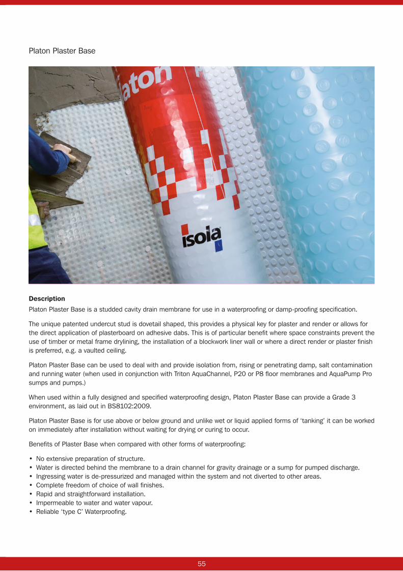
54 55
Description
Platon Plaster Base is a studded cavity drain membrane for use in a waterproofing or damp-proofing specification.
The unique patented undercut stud is dovetail shaped, this provides a physical key for plaster and render or allows for the direct application of plasterboard on adhesive dabs. This is of particular benefit where space constraints prevent the use of timber or metal frame drylining, the installation of a blockwork liner wall or where a direct render or plaster finish is preferred, e.g. a vaulted ceiling.
Platon Plaster Base can be used to deal with and provide isolation from, rising or penetrating damp, salt contamination and running water (when used in conjunction with Triton AquaChannel, P20 or P8 floor membranes and AquaPump Pro sumps and pumps.)
When used within a fully designed and specified waterproofing design, Platon Plaster Base can provide a Grade 3 environment, as laid out in BS8102:2009.
Platon Plaster Base is for use above or below ground and unlike wet or liquid applied forms of ‘tanking’ it can be worked on immediately after installation without waiting for drying or curing to occur.
Benefits of Plaster Base when compared with other forms of waterproofing:
• No extensive preparation of structure.• Water is directed behind the membrane to a drain channel for gravity drainage or a sump for pumped discharge.• Ingressing water is de-pressurized and managed within the system and not diverted to other areas.• Complete freedom of choice of wall finishes.• Rapid and straightforward installation.• Impermeable to water and water vapour.• Reliable ‘type C’ Waterproofing.
Platon Plaster Base
56 57
The product
Platon Plaster Base is manufactured from high-density polyethylene (HDPE) with a stud height of 5mm. Plaster Base is supplied in rolls 2m x 20m and is clear/translucent in colour.
It is recommended for internal applications only. Platon Plaster Base can be used in conjunction with other Platon membranes, above or below ground.
Installation
Platon Plaster Base can be applied to retained sound renders, brickwork, blockwork, stone or concrete. The quality and appearance of the applied finishes will be a direct reflection of the underlying substrate.
All surfaces must be of a sound, firm nature and any loose areas should be removed prior to application. Uneven, loose, or soft brick/stonework may need to be dubbed out to level off and stabilise the background.
Retaining sound cement render can be a good option if the substrate underneath is known to be in poor condition.
Gypsum based plaster, wallpaper and any buried timber must be removed as these materials can deteriorate over time in the presence of moisture.
Where necessary a fungicide wash should be applied to the wall surface.
Platon Plaster Base should not be used on floors.
Remove loose and soft plaster/render, wallpaper and embedded timbers. Dub out voids, hollows and loose areas of masonry using a cement mortar.
Offer up the membrane, hollow studs facing into the room, and fix in place using sealed Plaster Plugs (use Platon Sealing Rope).
Pull the membrane as tightly as possible against the structure to minimise hollow areas behind as these can interfere with the application of plaster or plasterboard.
Use a minimum of 13 fixings per square metre, spaced out in a regular ‘diamond’ pattern no more than 250mm apart. Drill through the membrane in the centre of a 4 stud cluster, rather than through the stud itself.
In some cases, additional fixings may be required in order to produce a stable and tight membrane layer. Fit the membrane tightly into and around corners to avoid damage when applying finishes.
Platon Plaster Base is joined by overlapping adjacent sheets by a minimum of 2 studs. Fix Platon Plaster Plugs as close as possible to the edge of the membrane.
Fixings should be made at 150mm centres along the joint.
Once all fixings are in place, clean the membrane surface thoroughly and ensure it is dry and free from dust.
Apply Platon Overtape along the joint with equal overlaps onto each sheet of membrane and press firmly into place. If for some reason the membrane edges are in tension or are likely to try and pull apart, reinforce the joint with Platon Cornerstrip before applying the Overtape.
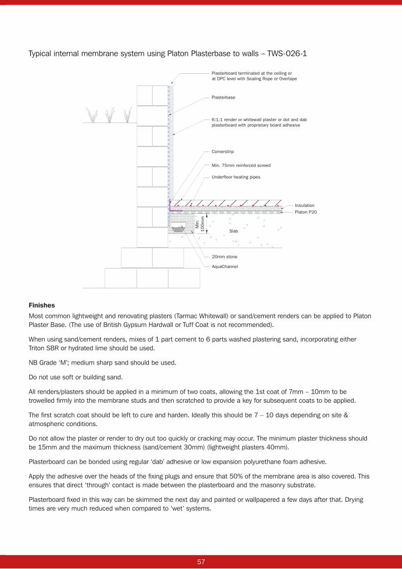
56 57
Plasterboard terminated at the ceiling orat DPC level with Sealing Rope or Overtape
6:1:1 render or whitewall plaster or dot and dabplasterboard with proprietary board adhesive
Cornerstrip
Min. 75mm reinforced screed
Underfloor heating pipes
Insulation
Platon P20
20mm stone
AquaChannel
Slab
Min
.1
00
mm
Plasterbase
Finishes
Most common lightweight and renovating plasters (Tarmac Whitewall) or sand/cement renders can be applied to Platon Plaster Base. (The use of British Gypsum Hardwall or Tuff Coat is not recommended).
When using sand/cement renders, mixes of 1 part cement to 6 parts washed plastering sand, incorporating either Triton SBR or hydrated lime should be used.
NB Grade ‘M’; medium sharp sand should be used.
Do not use soft or building sand.
All renders/plasters should be applied in a minimum of two coats, allowing the 1st coat of 7mm – 10mm to be trowelled firmly into the membrane studs and then scratched to provide a key for subsequent coats to be applied.
The first scratch coat should be left to cure and harden. Ideally this should be 7 – 10 days depending on site & atmospheric conditions.
Do not allow the plaster or render to dry out too quickly or cracking may occur. The minimum plaster thickness should be 15mm and the maximum thickness (sand/cement 30mm) (lightweight plasters 40mm).
Plasterboard can be bonded using regular ‘dab’ adhesive or low expansion polyurethane foam adhesive.
Apply the adhesive over the heads of the fixing plugs and ensure that 50% of the membrane area is also covered. This ensures that direct ‘through’ contact is made between the plasterboard and the masonry substrate.
Plasterboard fixed in this way can be skimmed the next day and painted or wallpapered a few days after that. Drying times are very much reduced when compared to ‘wet’ systems.
Typical internal membrane system using Platon Plasterbase to walls – TWS-026-1
58 59
Drainage
If free water is present or there is a risk of it occurring, provision must be allowed for the water to flow to natural drainage or a sump and pump. (BS8102:2009).
Triton Systems has a full range of sumps and pumps, control panels and water level alarms and monitors.
Roll size and ancillaries
Rolls of: 2M x 20MPlaster Plugs: box of 500 (at the rate of 13/M², 540 are used with a 40M² roll. Platon Sealing Rope: 5M roll (one roll per 100 Plaster Plugs) or use Plaster Plug Seals.Platon Overtape: 25M roll (one roll per full size roll of Plaster Base. Platon Cornerstrip: 10M roll, used as joint reinforcement.
Technical data
Membrane material: HDPE
Sheet thickness: 0.50 mm approximately
Stud height: 5mm
Roll weight: 19.2kg
Air gap volume: 3.2L/m²
Drainage capacity: 1.84L/m²
Storage: Rolls to be stored upright and under cover if possible
NBS clause: J40 (Flexible sheet tanking, damp proofing) 290

58 59
Description
Platon Plaster Mesh is a dimpled sheet cavity drain membrane for use in waterproofing or damp-proofing specification.
The bonded mesh layer on the front of the membrane allows the direct application of plasterboard (on adhesive dabs), plaster or render.
This is of particular benefit where space constraints prevent the use of timber or metal frame drylining or the installation of a blockwork liner wall or where a direct render or plaster finish is preferred, e.g. a vaulted ceiling.
Plaster Mesh can be used to deal with and provide isolation from, rising or penetrating damp, salt contamination and running water (when used in conjunction with Triton AquaChannel, P20 or P8 floor membranes and AquaPump Pro sumps and pumps).
When used within a fully designed and specified waterproofing design, Platon Plaster Mesh can provide a Grade 3 environment, as laid out in BS8102:2009.
Platon Plaster Mesh is for use above or below ground and unlike wet or liquid applied forms of ‘tanking’ it can be worked on immediately after installation without waiting for drying or curing to occur.
Benefits of Plaster Mesh when compared with other forms of waterproofing:
• No extensive preparation of structure. • Water is directed behind the membrane to a drain channel for gravity drainage or a sump for pumped discharge• Ingressing water is de-pressurized and managed within the system and not diverted to other areas.• Complete freedom of choice of wall finishes.• Rapid and straightforward installation.• Impermeable to water and water vapour.• Reliable ‘type C’ Waterproofing.
Platon Plaster Mesh
60 61
The product
Platon Plaster Mesh is manufactured from high-density polyethylene (HDPE) with a stud height of 8mm. Plaster Mesh is supplied in rolls measuring 2m x 20m and is clear/translucent in colour.
It is recommended for internal applications only. Platon Plaster Mesh can be used in conjunction with other Platon membranes, above or below ground.
Installation
Platon Plaster Mesh can be applied to retained sound renders, brickwork, blockwork, stone or concrete.
The quality and appearance of the applied finishes will be a direct reflection of the underlying substrate.
All surfaces must be of a sound, firm nature and any loose areas should be removed prior to application.
Uneven, loose, or soft brick/stonework may need to be dubbed out to level off and stabilise the background. Retaining sound cement render can be a good option if the substrate underneath is known to be in poor condition. Gypsum based plaster, wallpaper and any buried timber must be removed as these materials can deteriorate over time in the presence of moisture.
Where necessary a fungicide wash should be applied to the wall surface.
Platon Plaster Mesh can also be used on floors and the mesh can be useful when underfloor heating pipes need to be firmly located before a screed is laid. Small ‘zip’ ties threaded through the mesh provide a firm anchor without penetrating the membrane.
Remove loose and soft plaster/render, wallpapers and embedded timbers.
Dub out voids, hollows and loose areas of masonry using a cement mortar.
Offer up the membrane, mesh side facing into the room, and fix in place using sealed Plaster Plugs (use Platon Rope).
Pull the membrane as tightly as possible against the structure to minimise hollow areas behind as these can interfere with the application of plaster or plasterboard.
Use a minimum of 13 fixings per square metre, spaced out in a regular ‘diamond’ pattern no more than 250mm apart. Drill through the membrane in the centre of a 4-stud cluster, rather than through the stud itself.
In some cases, additional fixings may be required in order to produce a stable and tight membrane layer.
Fit the membrane tightly into and around corners to avoid damage when applying finishes.
Platon Plaster Mesh is joined by overlapping the edge of one sheet by another underneath by a minimum of 2 studs. Fix Platon Plaster Plugs through the studs as close as possible to the edge of the membrane.
Fixings should be made at 150mm centres along the joint.
Once all fixings are in place, clean the membrane surface thoroughly and ensure it is dry and free from dust. Apply Platon Overtape along the joint with equal overlaps of the tape onto each sheet of membrane and press firmly into place. If, for some reason the membrane edges are in tension or are likely to try and pull apart, reinforce the joint with Platon Cornerstrip before applying the Overtape.
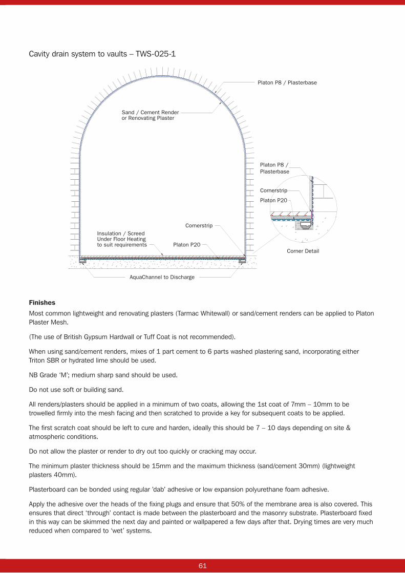
60 61
Finishes
Most common lightweight and renovating plasters (Tarmac Whitewall) or sand/cement renders can be applied to Platon Plaster Mesh.
(The use of British Gypsum Hardwall or Tuff Coat is not recommended).
When using sand/cement renders, mixes of 1 part cement to 6 parts washed plastering sand, incorporating either Triton SBR or hydrated lime should be used.
NB Grade ‘M’; medium sharp sand should be used.
Do not use soft or building sand.
All renders/plasters should be applied in a minimum of two coats, allowing the 1st coat of 7mm – 10mm to be trowelled firmly into the mesh facing and then scratched to provide a key for subsequent coats to be applied.
The first scratch coat should be left to cure and harden, ideally this should be 7 – 10 days depending on site & atmospheric conditions.
Do not allow the plaster or render to dry out too quickly or cracking may occur.
The minimum plaster thickness should be 15mm and the maximum thickness (sand/cement 30mm) (lightweight plasters 40mm).
Plasterboard can be bonded using regular ’dab’ adhesive or low expansion polyurethane foam adhesive.
Apply the adhesive over the heads of the fixing plugs and ensure that 50% of the membrane area is also covered. This ensures that direct ‘through’ contact is made between the plasterboard and the masonry substrate. Plasterboard fixed in this way can be skimmed the next day and painted or wallpapered a few days after that. Drying times are very much reduced when compared to ‘wet’ systems.
Platon P8 / Plasterbase
Corner Detail
AquaChannel to Discharge
Insulation / ScreedUnder Floor Heatingto suit requirements
Sand / Cement Renderor Renovating Plaster
Platon P8 / Plasterbase
Cornerstrip
Cornerstrip
Platon P20
Platon P20
Cavity drain system to vaults – TWS-025-1
62 63
Drainage
If free water is present or there is a risk of it occurring, provision must be allowed for the water to flow to natural drainage or a sump and pump. (BS8102:2009).
Triton Systems has a full range of AquaChannel drainage conduit and accessories, sumps and pumps, control panels and water level alarms and monitors.
Roll size and ancillaries
Rolls of: 2M x 20MPlaster Plugs: box of 500 (at the rate of 13/M2, 540 are used with a 40M² roll).Platon Rope: 5M roll (one roll per 100 Plaster Plugs) or use Plaster Plug Seals.Platon Overtape: 25M roll (one roll per full size roll of Plaster Mesh).Platon Cornerstrip: 10M roll, used as joint reinforcement.
Technical data
Sheet material: HDPE
Sheet thickness: 070 mm approximately
Stud height: 8mm
Unit weight: 0.700kg/m²
Air gap volume: 5.5L/m²
Compressive strength: 150 kN/m²
Colour: Clear/translucent
Service temperature range: -40°C to +80°C
Storage: Rolls to be stored upright and under cover if possible
NBS clause: J40 (Flexible sheet tanking, damp proofing) 290
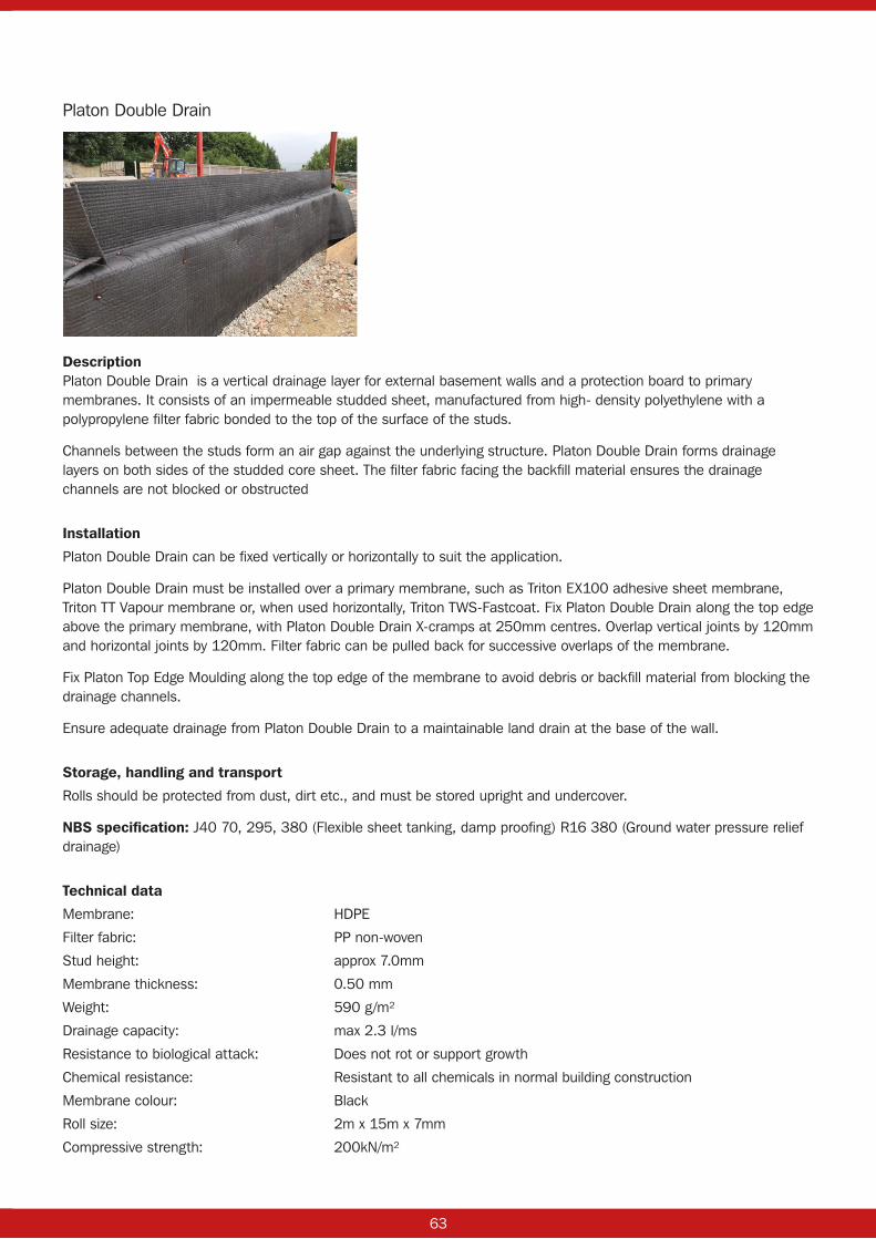
62 63
Platon Double Drain
DescriptionPlaton Double Drain is a vertical drainage layer for external basement walls and a protection board to primary membranes. It consists of an impermeable studded sheet, manufactured from high- density polyethylene with a polypropylene filter fabric bonded to the top of the surface of the studs.
Channels between the studs form an air gap against the underlying structure. Platon Double Drain forms drainage layers on both sides of the studded core sheet. The filter fabric facing the backfill material ensures the drainage channels are not blocked or obstructed
Installation
Platon Double Drain can be fixed vertically or horizontally to suit the application.
Platon Double Drain must be installed over a primary membrane, such as Triton EX100 adhesive sheet membrane, Triton TT Vapour membrane or, when used horizontally, Triton TWS-Fastcoat. Fix Platon Double Drain along the top edge above the primary membrane, with Platon Double Drain X-cramps at 250mm centres. Overlap vertical joints by 120mm and horizontal joints by 120mm. Filter fabric can be pulled back for successive overlaps of the membrane.
Fix Platon Top Edge Moulding along the top edge of the membrane to avoid debris or backfill material from blocking the drainage channels.
Ensure adequate drainage from Platon Double Drain to a maintainable land drain at the base of the wall.
Storage, handling and transport
Rolls should be protected from dust, dirt etc., and must be stored upright and undercover.
NBS specification: J40 70, 295, 380 (Flexible sheet tanking, damp proofing) R16 380 (Ground water pressure relief drainage)
Technical data
Membrane: HDPE
Filter fabric: PP non-woven
Stud height: approx 7.0mm
Membrane thickness: 0.50 mm
Weight: 590 g/m²
Drainage capacity: max 2.3 l/ms
Resistance to biological attack: Does not rot or support growth
Chemical resistance: Resistant to all chemicals in normal building construction
Membrane colour: Black
Roll size: 2m x 15m x 7mm
Compressive strength: 200kN/m²

64 65
Platon X Cramp
Description
Platon Double Drain X Cramps fis precisely between four of Platon Double Drain studs and provides a secure fixing for the membrane.
For best fit and fixing strength, remove filter fabric from the area of Double Drain to be fixed, offer up the X Cramp and pin into place, replace the filter fabric.
Pack: Bag of 60
Applications: With Platon Double Drain on external basement walls
Platon Brick Plug 10 x 75mm
Description
Platon Brick Plugs are used to fix Platon P8 to masonry or concrete substrates. A 10mm SDS drill bit is used, taken to a depth of 90mm. Brick Plugs are used in conjunction with Neoprene Seals or Platon Sealing Rope.
Platon Brick Plugs have a head of diameter 25 mm, and are shaped on the underside, like the back face of the Platon P8 studs. This gives an excellent transfer of loading from membrane to the substrate either when using the Neoprene seals or Rope.
There is a 5 mm blind hole in the shank of the plug for fixing the next layer onto the Platon Membrane, e.g. battens, using a screw of diameter of 5 or 6 mm, with screwing-in depth of max. 30 mm.
Pack: Box of 100 (order with or without Seals)
Delivery unit: Multiples of 100
Brick Plug Seals: Pre-fitted or supplied in a bag of 100
Platon Sealing Rope: 1 x 5m roll per 100 Brick Plugs if Neoprene Seals not used
Applications: Sealed system internal walls or vaults
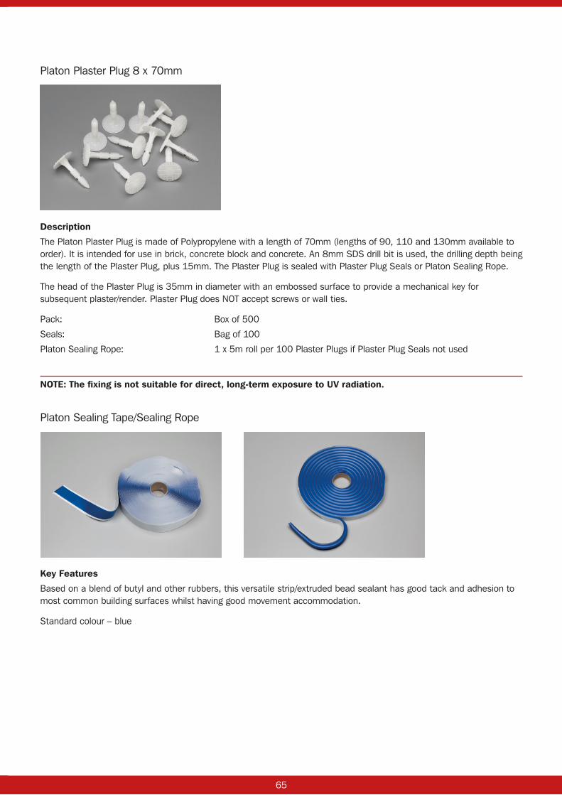
64 65
Platon Plaster Plug 8 x 70mm
Description
The Platon Plaster Plug is made of Polypropylene with a length of 70mm (lengths of 90, 110 and 130mm available to order). It is intended for use in brick, concrete block and concrete. An 8mm SDS drill bit is used, the drilling depth being the length of the Plaster Plug, plus 15mm. The Plaster Plug is sealed with Plaster Plug Seals or Platon Sealing Rope.
The head of the Plaster Plug is 35mm in diameter with an embossed surface to provide a mechanical key for subsequent plaster/render. Plaster Plug does NOT accept screws or wall ties.
Pack: Box of 500
Seals: Bag of 100
Platon Sealing Rope: 1 x 5m roll per 100 Plaster Plugs if Plaster Plug Seals not used
NOTE: The fixing is not suitable for direct, long-term exposure to UV radiation.
Platon Sealing Tape/Sealing Rope
Key Features
Based on a blend of butyl and other rubbers, this versatile strip/extruded bead sealant has good tack and adhesion to most common building surfaces whilst having good movement accommodation.
Standard colour – blue

66 67
Performance
The following performance data assumes good joint design. For non-standard situations please refer to our Technical Department.
Movement accommodation: ±15% when used in lap and cover joints
Adhesion: has good surface tack and adheres well to most building materials
Shear strength: 14N
Compression (force required to compress by 20%): 200N
UV light resistance: Very good
Chemical resistance: Good to diluted acids and alkalis. Not recommended for extreme chemical exposure
Service temperature range: –40°C to +110°C
Expected life: Platon Sealing Tape and Sealing Rope are durable materials and have a service life in line with Platon cavity drain membranes, dependent on the service temperature and joint design
Shelf life: 1 year
Elongation at break: 220%
Application
Surface preparation: All surfaces should be clean, dry and free from frost, grease and loose material. Seal mineral surfaces with TT55/LPA or TT Vapour Membrane for best results.
Application details: Should be applied directly from the reel onto one surface, pressing sufficiently to ensure adequate initial adhesion. Remove backing paper and apply other surface onto Sealing Tape or Rope pushing firmly to ensure good contact with the full width of the strip along the length of the joint
Application temperature range: +5°C to +30°C
Priming: Seal masonry with TT55/LPA or TT Vapour Membrane.
Packaging
Single strand reels on silicone release paper. Metres per reel and reels per carton depend on the thickness and width respectively.
Tolerance: thickness: ± 10% Tolerance: width: up to 15mm ± 1mm
15-25mm ± 1.5mm over 26mm ± 2mm
Bead sections available in 10mm diameter.
Tolerance: thickness: nominal to nominal less 12% Tolerance: width: nominal to nominal plus 12%
Health and safety
Platon Sealing Tape/Rope are non-hazardous in normal use.
Wash hands immediately after use.

66 67
Platon Overtape
Key Features
Based on a blend of butyl and other rubbers, Platon Overtape has a non-woven fabric backing which allows plaster and dab adhesive to bond to it. The versatile strip sealant has good tack and adhesion to most common building surfaces whilst having good movement accommodation.
Standard colour – black with grey or white fleece
Performance
The following performance data assumes good joint design. For non-standard situations please refer to our Technical Department.
Movement accommodation: ±15% when used in lap and cover joints
Adhesion: Has good surface tack and adheres well to PVC, many metals and plastics
Shear strength: 16.2N
Compression to seal: Positive pressure
Force to compress by 20%: 200N
UV light resistance: Excellent
Chemical resistance: Good to diluted acids and alkalis. Not recommended for extreme chemical exposure
Service temperature range: –40°C to +110°C
Expected life: Platon Overtape is a durable material and has a service life in line with Platon cavity drain membranes, dependent on the service temperature and joint design
Shelf life: 1 year
Elongation at break: 220%
Application
Surface preparation: All surfaces should be clean, dry and free from frost, grease and loose material.
Seal mineral surfaces with TT55/LPA or TT Vapour Membrane for best results.
Application details: Remove backing paper and apply directly from the reel onto membrane surface pressing firmly to ensure adequate adhesion along the length of the joint.
Application temperature range: +5°C to +45°C
Priming: Seal masonry with TT55/LPA or TT Vapour Membrane
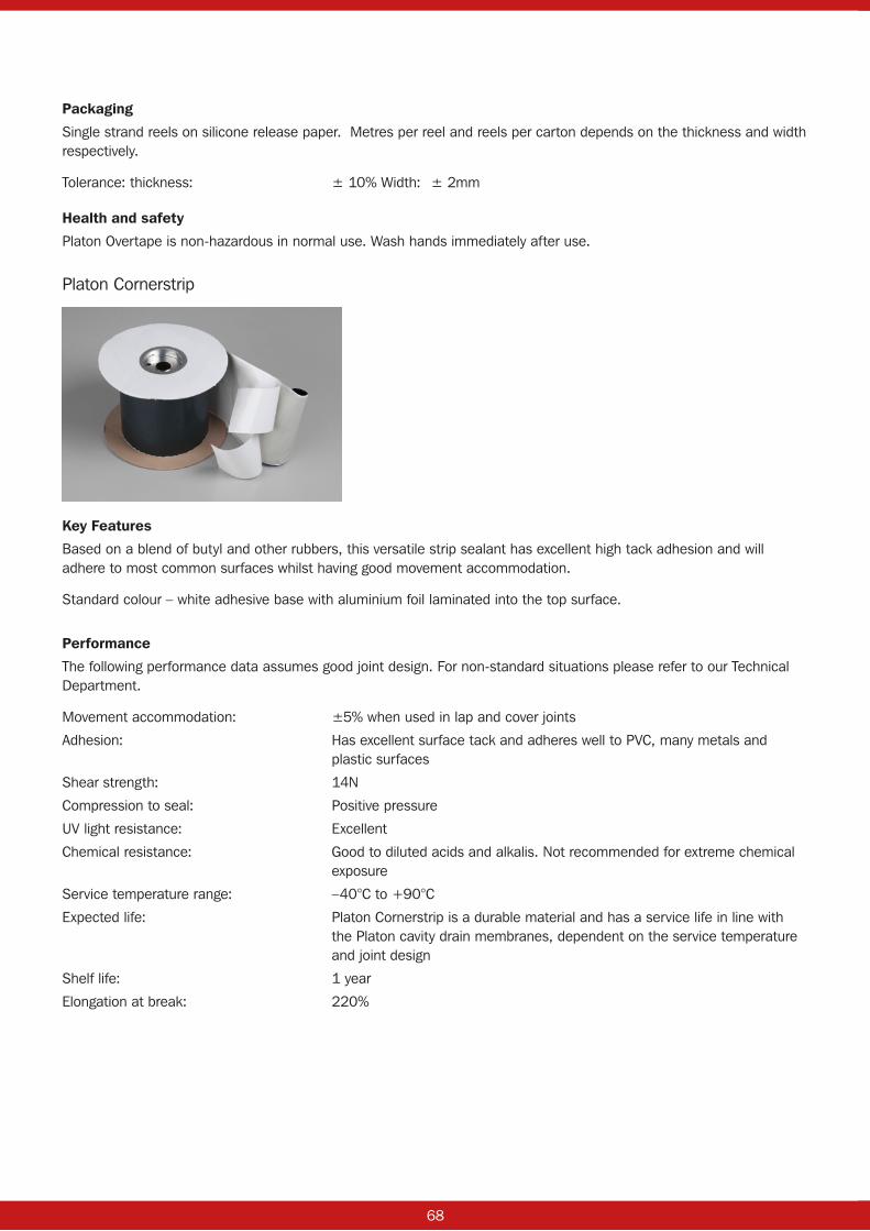
68 69
Packaging
Single strand reels on silicone release paper. Metres per reel and reels per carton depends on the thickness and width respectively.
Tolerance: thickness: ± 10% Width: ± 2mm
Health and safety
Platon Overtape is non-hazardous in normal use. Wash hands immediately after use.
Platon Cornerstrip
Key Features
Based on a blend of butyl and other rubbers, this versatile strip sealant has excellent high tack adhesion and will adhere to most common surfaces whilst having good movement accommodation.
Standard colour – white adhesive base with aluminium foil laminated into the top surface.
Performance
The following performance data assumes good joint design. For non-standard situations please refer to our Technical Department.
Movement accommodation: ±5% when used in lap and cover joints
Adhesion: Has excellent surface tack and adheres well to PVC, many metals and plastic surfaces
Shear strength: 14N
Compression to seal: Positive pressure
UV light resistance: Excellent
Chemical resistance: Good to diluted acids and alkalis. Not recommended for extreme chemical exposure
Service temperature range: –40°C to +90°C
Expected life: Platon Cornerstrip is a durable material and has a service life in line with the Platon cavity drain membranes, dependent on the service temperature and joint design
Shelf life: 1 year
Elongation at break: 220%

68 69
Application
Surface preparation: All surfaces should be clean, dry and free from frost, grease and loose material. Seal mineral surfaces with TT55/LPA or TT Vapour Membrane for best results
Application details: Remove backing paper and apply directly from the reel onto membrane surface pressing firmly to ensure adequate adhesion along the length of the joint
Application temperature range: +2°C to +30°C
Priming: Seal masonry with TT55/LPA or TT Vapour Membrane
Packaging
Single strand reels on silicone release paper. Metres per reel and reels per carton depends on the thickness and width respectively.
Health and safety
Platon Cornerstrip is non-hazardous in normal use. Wash hands immediately after use.

70 71

70 71

1391 01/21
Triton Systems
Units 3 – 5 Crayford Commercial Centre, Greyhound Way, Crayford, Kent DA1 4HF
Tel: 01322 318830 Fax: 01322 524017 Email: [email protected]
Triton Chemical Manufacturing Co Ltd trading as Triton Systems
www.tritonsystems.co.uk