“plc controlled elevator modelgnu.inflibnet.ac.in/bitstream/123456789/1569/1/plc controlled... ·...
TRANSCRIPT
UDP ON
“PLC CONTROLLED ELEVATOR MODEL”
In the partial fulfillment of the requirements for the award of the degree of
DIPLOMA IN ENGINEERING
OF
MECHATRONICS
SUBMITTED BY:-
KALSARIYA GANPAT (013)
PATOLIYA MAULIK (049)
KHUNT HARDIK (060)
PATEL CHINTAN (062)
Guided By: Pratik A. Solanki
Lecturer in B.S.Patel Polytechnic, Mehsana

2
CERTIFICATE
This is to Certify that the project entitled “PLC CONROLLED ELEVATOR MODEL”
Submitted in partial fulfillment of the requirement for the award of DIPLOMA
ENGINEERING under four walls of SHRI B.S.PATEL POLYTECHNIC is faithful record of
the bona fide project work,
The following candidates are under my guidance and supervision.
1. KALSARIYA GANPAT S. 106440320013
2. PATEL PARTH 106440320041
3. PATOLIYA MAULIK 106440320049
4. KHUNT HARDIK 106440320060
5. PATEL CHINTAN 106440320062
________________ _________________ Mr. K. P. PATEL Mr. P. A. SOLANKI

3
(H.O.D. mechanical) (Internal Guide Teacher)
Acknowledgement
I acknowledge my indebtedness and convey my sincere thanks to our project guide
Mr.P.A.SOLANKI, faculty of Dept. of MECHATRONICS., B.S.P.P. who sincerely helped us by giving
inspiration, new ideas and infrastructure throughout the semesters. I would also like to thank
Mechatronics department of SHRI B.S.PATEL POLYTECHNIC to give us such platform for making this
project successful. I also convey my thanks to the faculties of my college and my group members
who helped me whole heartdly during the entire session. At last I again convey my special thanks
to the project guides who decided to shows the model of this project at the workshop arranged at
that time.
4
Abstract
Though practically elevators are controlled by PLC, still we employed it, because elevator is
an appropriate system where we can explore a lot of feature of the PLC. As it is a mere model only,
while shifting to practical elevator some module of our model need to be replaced, viz. DC motor
drive need to be replaced by an induction motor drive, a weight counter-balancing technique
should be employed. But as our target of doing this project is mainly PLC oriented, we mainly
focused in PLC ladder logic and how to connect an external hardware/system with the PLC to
control that hardware.

5
INDEX
Sr No. CONTENT PAGE NO.
1 BASICS OF PLC 6
1.1 Introduction 7
1.2 Architecture of PLC 9
1.3 Advantages of PLC 10
1.4 PLC operation 11
. 1.5 PLC terminology 11
. 1.6 Basic Requirement 14
1.7 Timer function block 14
1.8 Counter function block 16
2 DESCRIPTION OF MODEL 20
2.1 Objectives 21
2.2 Model description 22
2.3 Schematic diagram of elevator 23
2.4 Wireframe model of elevator model 24
2.5 Torque calculation 25
3 TYPES OF SENSOR 23
3.1 What is sensor? 24
3.2 factor to be consider when choosing a sensor 24
3.3 Limit switch 25
3.4 Proximity sensor 26
4 DESCRIPTION OF PROGRAM 28
4.1 Ladder description 29
4.2 PLC which is used 30
4.3 Input of the system 30
4.4 Output of the system 30
4.5 Ladder Diagram 31
4.6 Description of program 33
4.7 Future scope of improvement 34
4.8 Conclusion 35
Bibliography 36

6
Chapter-1
BASICS OF PLC

1.1 Introduction
PLC is actually an industrial microcontroller system (in more recent
processors instead of microcontrollers) where we have har
adapted to industrial environment. Blocks came with typical components, which PLC consist of, is
found in the following picture. Special atten
these blocks you find protection needed in isolating a CPU blocks from damaging i
industrial environment can bring to a CPU via input lines.
for writing a program (often in ladder diagram)
Central processing unit is the
microcontrollers. Communication, interconnected among other parts of PLC controller, program
execution, memory operation, overseeing input and setting up of an output. PLC controllers have
complex routines for memory check up in order to ensure that PLC memor
(memory check up is done for safety reasons
PLC is actually an industrial microcontroller system (in more recent
trollers) where we have hardware and software specifically
environment. Blocks came with typical components, which PLC consist of, is
. Special attention needs to be given to input and output, because in
these blocks you find protection needed in isolating a CPU blocks from damaging i
industrial environment can bring to a CPU via input lines. Program unit is usually computer used
often in ladder diagram).
Central processing unit is the brain of a PLC controller. CPU itself is usually one of the
ommunication, interconnected among other parts of PLC controller, program
execution, memory operation, overseeing input and setting up of an output. PLC controllers have
complex routines for memory check up in order to ensure that PLC memory was not
k up is done for safety reasons).
7
times we meet
ware and software specifically
environment. Blocks came with typical components, which PLC consist of, is
to be given to input and output, because in
these blocks you find protection needed in isolating a CPU blocks from damaging influence that
unit is usually computer used
of a PLC controller. CPU itself is usually one of the
ommunication, interconnected among other parts of PLC controller, program
execution, memory operation, overseeing input and setting up of an output. PLC controllers have
y was not damage

8
PLC controllers can be reprogrammed through a computer, but also through manual
programs (console). This practically means that each PLC controller can beprogrammed througha
computer if you have the software needed for programming. Today’s Transmission computers are
ideal for reprogramming of PLC controller in factory itself. This is of great importance in industry.
Once the system is corrected, it is also important to read the right program into a PLC again. It is
also good to check from time to time whether program in a PLC has not changed. This helps to
avoid hazardous situation in factory rooms.
Prior to PLC, many control tasks were solved with contactor or relay controls. This is often
referred to as hardwired control. Circuit diagram had to be designed, electrical components
specified and wiring lists created. Electricians would then wire the components necessary to
perform a specific task. If an error was made, the wires had to be reconnected correctly. A change
in function or system expansion required extensive components and rewiring.
1.2 Architecture of PLC
The programmable logic controller is basically computer-based and therefore, their architecture is
very similar to computer architecture. The memory contains operating system stored in fixed
memory like ROM, rather than the disk in case of computer. The application program is stored in
read-write portion of memory.
All programmable controllers contain a central processing unit (CPU), memory, power
supply, input/output (I/O) modules and programming devise.
The operating system is the main workhorse of the system. It is necessary to distinguish
between the instructions used by operating system to command the microprocessor and the
instruction used by the programmable controller to handle the specific control problem. The
operation system performs the following tasks:
Execution of application program.
Memory management.
Communication between programmable controller and the other units.

9
I/O interfaces handling.
Diagnostics.
Resource sharing.
The CPU, upon receiving instruction from the memory together with feedback on the
status of the I/P-O/P devices, generates commends to the output by means of the o/p
modules these commands control the o/p elements on a machine or process device such as
relay coils, solenoid valves, indicator lamp and motor starters are typical load to be
controlled.
During program execution the processor reads all the inputs, takes these values and
according to control application program, energizes the outputs, thus solving the ladder
network.
1.3 Advantages of PLC
The same, as well as more complex tasks can be done with a PLC. Wiring between devices and
relay contacts is done in the PLC program. Hard-wiring, though still required to connect field’s
devices, is less intensive. Modifying the application and correcting errors easier to handle. It is
create and change a program in a PLC than it is to wire and re-write a circuit.
Following are just a few of the advantages of PLCs:
• Smaller physical size than hand-wire solutions.
• Easier and faster to make changes.
• PLCs have integrated diagnostics and override function.
• Diagnostics are centrally available.
• Applications can be immediately documented.
• Application can be duplicated faster and less expansively.
10
1.4 PLC Operations
1. INPUT SCAN: scans the state of the input (sensing devices, switches and pushbuttons,
proximity sensor, pressure switches etc.).
2. PROGRAM SCAN : executes the program logic
3. OUTPUT SCAN: energize/de-energize the output (valves, solenoids, motor, actuators,
pumps).
4. HOUSEKEEPING: communication checking with the software and the perform other
requests according to their preference.
1.5 PLC Terminology
The language of PLCs consists of a commonly used set of terms; many of which are unique to
PLCs. In order to understand the ideas and concepts of PLCs, an understanding of these terms is
necessary.
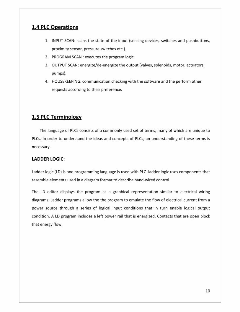
LADDER LOGIC:
Ladder logic (LD) is one programming language is used with PLC .ladder logic uses components that
resemble elements used in a diagram format to describe hand-wired control.
The LD editor displays the program as a graphical representation similar to electrical wiring
diagrams. Ladder programs allow the the program to emulate the flow of electrical current from a
power source through a series of logical input conditions that in turn enable logical output
condition. A LD program includes a left power rail that is energized. Contacts that are open block
that energy flow.
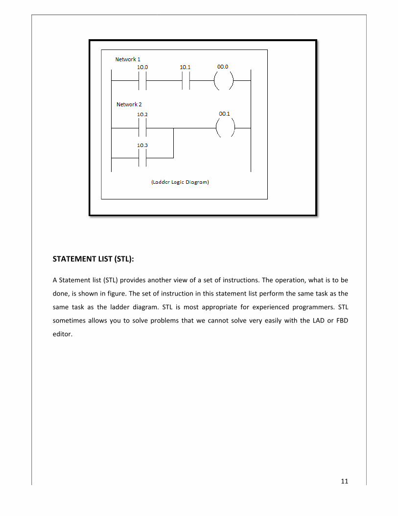
STATEMENT LIST (STL):
A Statement list (STL) provides another view of a set of instructi
done, is shown in figure. The set of instruction in this statement list perform the same task as the
same task as the ladder diagram. STL is most appropriate for experienced programmers.
sometimes allows you to solve problems that we cannot solve very easily with the LAD or FBD
editor.
A Statement list (STL) provides another view of a set of instructions. The operation, what is to be
done, is shown in figure. The set of instruction in this statement list perform the same task as the
same task as the ladder diagram. STL is most appropriate for experienced programmers.
roblems that we cannot solve very easily with the LAD or FBD
11
ons. The operation, what is to be
done, is shown in figure. The set of instruction in this statement list perform the same task as the
same task as the ladder diagram. STL is most appropriate for experienced programmers. STL
roblems that we cannot solve very easily with the LAD or FBD

FUNCTION BLOCK DIAGRAMS (FBD):
Function Block Diagrams (FBD) provides another view of a set of instructions. Each function has a
name to designate its specific task. Functions are indicated by a rectangle. Inputs are shown on the
left-hand side of the rectangle and outputs are shown on
shown here performs the same function as same function as shown
statement list. The graphical logic gate style of representation is good for following program flow.
FUNCTION BLOCK DIAGRAMS (FBD):
Function Block Diagrams (FBD) provides another view of a set of instructions. Each function has a
name to designate its specific task. Functions are indicated by a rectangle. Inputs are shown on the
hand side of the rectangle and outputs are shown on the figure. The function block diagram
shown here performs the same function as same function as shown by the ladder diagram and
The graphical logic gate style of representation is good for following program flow.
12
Function Block Diagrams (FBD) provides another view of a set of instructions. Each function has a
name to designate its specific task. Functions are indicated by a rectangle. Inputs are shown on the
the figure. The function block diagram
by the ladder diagram and
The graphical logic gate style of representation is good for following program flow.

1.6 Basic Requirement
In PLC programming in order to create or change a program. The following items are needed:
• PLC
• Programming Device
• Programming Software
• Connector cable
Throughout our training we used the S7
Siemens the above items are:
• PLC :(S7-200)
• Programming Device: (Personal Computer)
• Programming Software :(Step 7
• Connector cable: (PC/PPI Cable)[PPI: Point to Point Interface]
1.7 Timer Function Block
Timers are devices that count increments of time. Timers are represented by boxes in
ladder logic. When a timer receives an enable. The timer starts to time. The timer starts to time.
The timer compares its current time with the preset time. The output of
as the current time is less than the
time the timer output is logic 1.S7
Delay(TONR), and Off-Delay(TOF).
On-Delay Timer (TON):
in order to create or change a program. The following items are needed:
we used the S7-200 (Siemens) because of its ease of use. For the setup of
Programming Device: (Personal Computer)
Programming Software :(Step 7-MicroWIN 32)
Connector cable: (PC/PPI Cable)[PPI: Point to Point Interface]
Timers are devices that count increments of time. Timers are represented by boxes in
ladder logic. When a timer receives an enable. The timer starts to time. The timer starts to time.
The timer compares its current time with the preset time. The output of the timer is logic 0 as long
as the current time is less than the present time. When the current time is greater than
time the timer output is logic 1.S7-200 uses three types of timers: On-Delay(TON), Retentive On
13
in order to create or change a program. The following items are needed:
200 (Siemens) because of its ease of use. For the setup of
Timers are devices that count increments of time. Timers are represented by boxes in
ladder logic. When a timer receives an enable. The timer starts to time. The timer starts to time.
the timer is logic 0 as long
time. When the current time is greater than the preset
Delay(TON), Retentive On-

When the On-Delay timer (TON) receives an enable (logic 1) at
amount of time (preset time-PT) passes before the timer bit (T
function internal to the timer and is not shown on the symbol. The timer resets to the starting
time when the enabling input goes to logic 0.
Retentive On-Delay (TONR):
The retentive On-Delay timer (TONR) function in a similar manner to the On
There is one difference. The retentive On
does not reset when the input goes off. The timer must be reset with a RESET(R) instruction.
Off-Delay (TOF):
The Off-Delay timer is used to delay an output off for a fixed period of time after the input turns
off. When the enabling bit turns on the timer bit turns on
When the input turns off, the timer counts until the preset time has elapsed before the timer bit
turns off.
Delay timer (TON) receives an enable (logic 1) at its input (IN), a predetermined
PT) passes before the timer bit (T-bit); turns oo. The T
function internal to the timer and is not shown on the symbol. The timer resets to the starting
s to logic 0.
Delay timer (TONR) function in a similar manner to the On-delay timer (TON).
There is one difference. The retentive On-Delay timer times as long as the enabling input is on, but
hen the input goes off. The timer must be reset with a RESET(R) instruction.
Delay timer is used to delay an output off for a fixed period of time after the input turns
off. When the enabling bit turns on the timer bit turns on immediately and the value is set to 0.
When the input turns off, the timer counts until the preset time has elapsed before the timer bit
14
input (IN), a predetermined
bit); turns oo. The T-bit is a logic
function internal to the timer and is not shown on the symbol. The timer resets to the starting
delay timer (TON).
Delay timer times as long as the enabling input is on, but
hen the input goes off. The timer must be reset with a RESET(R) instruction.
Delay timer is used to delay an output off for a fixed period of time after the input turns
immediately and the value is set to 0.
When the input turns off, the timer counts until the preset time has elapsed before the timer bit

1.8 Counter Function Block
Counters used in PLCs serve the same function as mechanical counters. Counters compare an
accumulated value to a preset value to
commonly use counters include the following:
Count to a preset value and cause an event to occur until the count reaches a preset value.
For example: A bottling machine may
packaging.
Counters are represented by boxes in ladder logic.
time the input transitions from off (logic 0) to on (logic 1). The counters are reset when a RESET
instruction is executed. PLC uses three
and Up-Down counter (CTUD).
Up Counter:
The up counter counts up from a current value to a preset value (PV).Input CU is the count input.
Each time CU transitions from logic
the reset. A preset count value is stored in PV input. If the current count is equal to or greater than
the preset value stored in PV, the output bit (Q) turns on (not shown).
Counter Function Block
Counters used in PLCs serve the same function as mechanical counters. Counters compare an
accumulated value to a preset value to control circuit functions. Control application that
commonly use counters include the following:
use an event to occur until the count reaches a preset value.
machine may use a counter to count bottles into groups of six for
Counters are represented by boxes in ladder logic. Counters increment/decrement one count each
time the input transitions from off (logic 0) to on (logic 1). The counters are reset when a RESET
instruction is executed. PLC uses three types of counters: up counter (CTU), down counter (CTD),
The up counter counts up from a current value to a preset value (PV).Input CU is the count input.
logic 0 to logic 1 the counter increments by a count of 1. Input
the reset. A preset count value is stored in PV input. If the current count is equal to or greater than
the preset value stored in PV, the output bit (Q) turns on (not shown).
15
Counters used in PLCs serve the same function as mechanical counters. Counters compare an
control circuit functions. Control application that
use an event to occur until the count reaches a preset value.
use a counter to count bottles into groups of six for
Counters increment/decrement one count each
time the input transitions from off (logic 0) to on (logic 1). The counters are reset when a RESET
down counter (CTD),
The up counter counts up from a current value to a preset value (PV).Input CU is the count input.
1 the counter increments by a count of 1. Input R is
the reset. A preset count value is stored in PV input. If the current count is equal to or greater than

Down Counter:
The down counter counts down from the preset
logic 1. When the current valve is equal to zero the counter output bit (Q) turns on (not shown).
The counter resets and loads the current valve with
enabled.
Up-Down Counter:
ounts down from the preset value (PV) each time CD transition from logic 0 to
logic 1. When the current valve is equal to zero the counter output bit (Q) turns on (not shown).
The counter resets and loads the current valve with preset value (PV) when the load input (LD) is
16
PV) each time CD transition from logic 0 to
logic 1. When the current valve is equal to zero the counter output bit (Q) turns on (not shown).
PV) when the load input (LD) is
17
Up down counter count up and/or down. These are called CTUD, CTU, or CTD. When executing the
CTUD instruction while the counter up instruction variable UP is ON, the execution is similar with
the CTU instruction (up-counter). When variable UP is OFF, the execution is similar with the CTD
(down-counter) instruction.
After executing the CTUD instruction:
If the current value CV is equal to or greater than the preset value PV, variable Q and variable QU
are turned ON.
If the current value CV is equal to or less than zero, the variable Q and variable QD are turned ON.

18
Chapter-2
DESCRIPTION OF MODEL

19
2.1 Objective
To control the elevators of any multi storied building/shopping mall etc. The problem concern the
logic required to move elevators between floors according to the following constraints.
Each floor has a button to request upward or downward movement.
When the elevator gets multiple requests from different floors it will serve them according to first-
come-first-serve basis. Also the ladder logic should be that much of flexible so that the serving
technique can be changed according to the requirement (like nearest-floor-first, floor-having
more-people-first etc.)
The current floor number will be shown within the lift by a small display.
2.2 Model Description
The Model Consists of:-
• A Small wooden box in place of original lift.
• A Steel carriage which helps the lift to up & down smoothly.
• A pulley & rope system
• A D.C. motor, driving the pulley to make the lift up & down
• Some electronics components are attached with this model.
Those are :-
• 24 v D.C. motor
• Motor drive circuit
• Push buttons
• Proximity sensors

20

21

22
2.5 Torque Calculation
� Tension in Tight side T1=m*g
=200*9.8
=1960 N
� Tension in slack sideT2=P
T1/T2=���∗⍬�
Where, ⍬=Contact angle
µ=Co-efficient of friction
1960/T2=���.∗��
T2=1960/2.193
T2=p=894 N
� Torque M=P*R
=894*25
=22350 N mm
M =22.350 N m

23
Chapter 3
TYPES OFSENSOR

24
3.1 What is Sensor?
A sensor is adevice that measures a physical quantity and converts it into a signal which can be
read by an observer or by an instrument. For example, a mercury thermometer converts the
measured temperature into the expansion and contraction of a liquidwhich can be read on a
calibrated glass tube.
Sensors are devices used to provideinformation on the presence or absence ofan object.
Sensors are used in everyday objects such as touch-sensitive elevator buttons (tactile sensor) and
lamps which dim or brighten by touching the base. There are also innumerable applications for
sensors of which most people are never aware. Applications include cars, machines, aerospace,
medicine, manufacturing and robotics.
A sensor is a device which receives and responds to a signal when touched. A sensor's sensitivity
indicates how much the sensor's output changes when the measured quantity changes.
3.2 Factors to consider when choosing a sensor.
� Accuracy - The statistical variance about the exact reading.
� Calibration - Required for most measuring systems since their readings will drift over time.
� Cost
� Environmental - Sensors typically have temperature and/or humidity limits.
� Range - Limits of measurement or the sensor.
� Repeatability - The variance in a sensor's reading when a single condition is repeatedly
measured.
� Resolution - The smallest increment the sensor can detect.
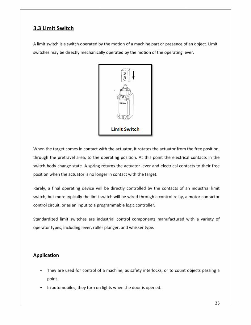
3.3 Limit Switch
A limit switch is a switch operated by the motion of a mac
switches may be directly mechanically operated by the motion of the operating lever.
When the target comes in contact with the actuator, it rotates the actuator from the free position,
through the pretravel area, to the operating position. At this point the electrical contacts in the
switch body change state. A spring returns the actuator lever and electrical contacts to their free
position when the actuator is no longer in
Rarely, a final operating device will be directly controlled by the contacts of an industrial limit
switch, but more typically the limit switch will be wired through a control
control circuit, or as an input to a programmable logic controller
Standardized limit switches are industrial control components manufactured with a
operator types, including lever, roller plunger, and whisker type.
Application
• They are used for control of a machine, as safety
point.
• In automobiles, they turn on lights when the door is opened.
is a switch operated by the motion of a machine part or presence of an object.
switches may be directly mechanically operated by the motion of the operating lever.
When the target comes in contact with the actuator, it rotates the actuator from the free position,
area, to the operating position. At this point the electrical contacts in the
switch body change state. A spring returns the actuator lever and electrical contacts to their free
position when the actuator is no longer in contact with the target.
final operating device will be directly controlled by the contacts of an industrial limit
switch, but more typically the limit switch will be wired through a control relay, a motor
programmable logic controller.
it switches are industrial control components manufactured with a
operator types, including lever, roller plunger, and whisker type.
They are used for control of a machine, as safety interlocks, or to count objects passing a
In automobiles, they turn on lights when the door is opened.
25
hine part or presence of an object. Limit
switches may be directly mechanically operated by the motion of the operating lever.
When the target comes in contact with the actuator, it rotates the actuator from the free position,
area, to the operating position. At this point the electrical contacts in the
switch body change state. A spring returns the actuator lever and electrical contacts to their free
final operating device will be directly controlled by the contacts of an industrial limit
, a motor contactor
it switches are industrial control components manufactured with a variety of
or to count objects passing a

• In industry, limit switches are used to limit
• operations or to detect moving items on a conveyor system
3.4 Proximity sensor
A proximity sensor is a sensor able to detect the presence of nearby objects without any physical
contact.
A proximity sensor often emits an
(infrared, for instance), and looks for changes in the
The object being sensed is often referred to as the proximity sensor's target. Different proximity
sensor targets demand different sensors.
A capacitive photoelectric sensor
sensor always requires a metal target.
The maximum distance that this sensor can detect is defined "nominal range". Some sensors have
adjustments of the nominal range or means to report a graduated detection distance.
Proximity sensors can have a high
mechanical parts and lack of physical contact between sensor and the sensed object.
In industry, limit switches are used to limit the travel of machine parts, sequence
operations or to detect moving items on a conveyor system
able to detect the presence of nearby objects without any physical
A proximity sensor often emits an electromagnetic field or a beam of electromagnetic radiation
, for instance), and looks for changes in the field or return signal.
The object being sensed is often referred to as the proximity sensor's target. Different proximity
sensor targets demand different sensors.
might be suitable for a plastic target; An inductive
sensor always requires a metal target.
The maximum distance that this sensor can detect is defined "nominal range". Some sensors have
ts of the nominal range or means to report a graduated detection distance.
Proximity sensors can have a high reliability and long functional life because of the absence of
mechanical parts and lack of physical contact between sensor and the sensed object.
26
the travel of machine parts, sequence
able to detect the presence of nearby objects without any physical
electromagnetic radiation
The object being sensed is often referred to as the proximity sensor's target. Different proximity
inductive proximity
The maximum distance that this sensor can detect is defined "nominal range". Some sensors have
ts of the nominal range or means to report a graduated detection distance.
because of the absence of
mechanical parts and lack of physical contact between sensor and the sensed object.
27
Application
• Vibration measurements of rotating shafts in machinery.
• Sheet breaks sensing in paper machine.
• Conveyor systems
• Ground proximity warning system for aviation safety.
• A proximity sensor adjusted to a very short range is often used as a touch switch.

28
Chapter-4
DESCRIPTION OF PROGRAM
29
4.1 Ladder description
The ladder diagram has been designed in step-7 microWIN 32 software (made by seimens). It
has been designed for multi level or multi storied building. The ladder has designed in such a
way, so that it can be easily applied to a building having any number of floors.
The ladder has been mainly three parts(or threads) which are running simultaneously. The first
thread is running to check the status of push buttons placed in different floors and store them
in a queue. The second one is used to track the current position of the lift and store them in a
temporary memory. And the third one is used to serve the request stored in the queue as they
were stored (i.e. first-in-first-out). To perform this kind of operation an inbuilt data structure
and some readymade blocks have been used.

30
4.2 PLC which is used
We used the S7-200 (Siemens) because of its ease of use. For the setup of Siemens the above
Items are:
• PLC :(S7-200)
• Programming Device: (Personal Computer)
• Programming Software :(Step 7-MicroWIN 32)
• Connector cable: (PC/PPI Cable)[PPI: Point to Point Interface]
4.3 Input of the system
from PLC:
Signal coming from push buttons placed in different floor.
Four proximity sensor which takes inputs from position of the lift in floor.
4.4 Output of the system
Signal to drive the motor in clockwise direction.
Signal to drive the motor in anti-clockwise direction.
External voltage source for power source to the DC motor.

4.5 Ladder Diagram
31

32
33
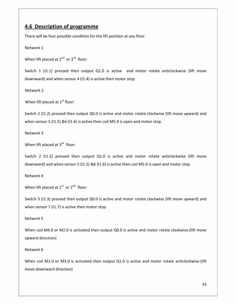
4.6 Description of programme
There will be four possible condition for the lift position at any floor.
Network 1
When lift placed at 2nd
or 3rd
floor:
Switch 1 (I1.1) pressed then output Q1.0 is active and motor rotate anticlockwise (lift move
downward) and when sensor 4 (I1.4) is active then motor stop
Network 2
When lift placed at 1st
floor:
Switch 2 (I1.2) pressed then output Q0.0 is active and motor rotate clockwise (lift move upward) and
when sensor 5 (I1.5) &6 (I1.6) is active then coil M5.0 is open and motor stop.
Network 3
When lift placed at 3rd
floor:
Switch 2 (I1.2) pressed then output Q1.0 is active and motor rotate anticlockwise (lift move
downward) and when sensor 5 (I1.5) &6 (I1.6) is active then coil M5.0 is open and motor stop.
Network 4
When lift placed at 1st
or 2nd
floor:
Switch 3 (I1.3) pressed then output Q0.0 is active and motor rotate clockwise (lift move upward) and
when sensor 7 (I1.7) is active then motor stop.
Network 5
When coil M4.0 or M2.0 is activated then output Q0.0 is active and motor rotate clockwise.(lift move
upward direction)
Network 6
When coil M1.0 or M3.0 is activated then output Q1.0 is active and motor rotate anticlockwise.(lift
move downward direction)

34
4.7 future scope of improvement
This model can be improved further as described below-
� Implement some techniques like, Nearest-Floor-First or Floor-Having-More-People-First to
save both time and consumed power.
� Will Add Weight sensor within the lift to set a maximum limit of weight the lift can carry.
� Will add weight sensor to each floor, to know which floor has the maximum crowd.
� A weight counter balancing technique should be employed to operate it practically.
� More security (like ringing of an alarm when the weight of the lift crosses the preset
maximum level) may be employed.

35
4.8 Conclusion
Before starting this project it was a challenge for us to develop proper ladder logic as we
beginner in the field of PLC programming. Gradually we managed to design the ladder by
practicing different kinds of PLC programming.
After designing the ladder I faced another challenge to interface the hardware system (i.e. model
of the lift) with the PLC.
As it is mere model, it may not match totally with the components used practically. But it can
give a good visualization of the practical elevation operation. Also PLC is not used in elevator
generally. Still we have used PLC as elevation process controller because it is a good area to apply
the full strength of PLC.

36
Bibliography
www.plcs.net
www.wikepedia.com
www.google.com