plc omron zen-quick_guide
DESCRIPTION
Quick Guide Omron ZenTRANSCRIPT
OMRON ELECTRONICS, S.A. Page 1
ZENQuick Guide
THIS MANUAL CONTAINS:
1 FEATURES
2 FUNCTIONALITY
3 HANDLING THE EQUIPMENT
4 CONNECTIONS
5 I/O ADDRESSING
6 CREATING A PROGRAM
7 PROGRAMMING FUNCTIONS
8 TROUBLESHOOTING
9 ACCESSORIES
1 Features ZEN Programmable Logic Module
OMRON ELECTRONICS, S.A. Page 2
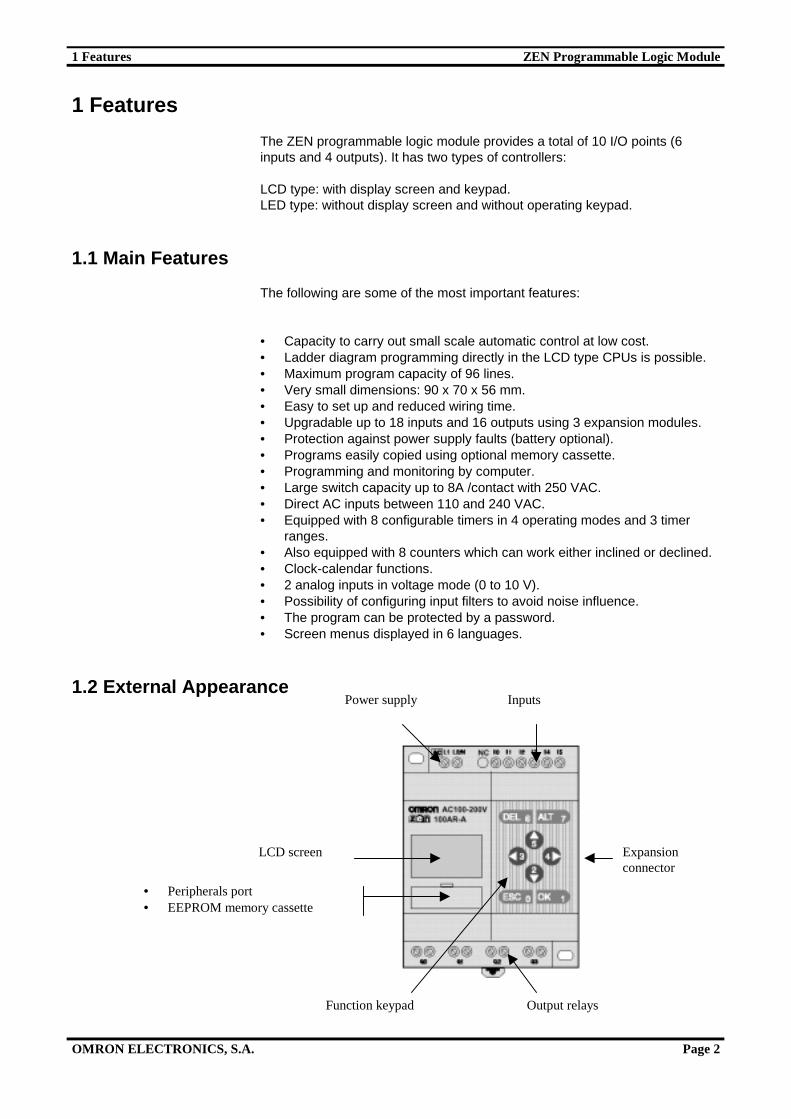
1 Features
The ZEN programmable logic module provides a total of 10 I/O points (6inputs and 4 outputs). It has two types of controllers:
LCD type: with display screen and keypad.LED type: without display screen and without operating keypad.
1.1 Main Features
The following are some of the most important features:
• Capacity to carry out small scale automatic control at low cost.• Ladder diagram programming directly in the LCD type CPUs is possible.• Maximum program capacity of 96 lines.• Very small dimensions: 90 x 70 x 56 mm.• Easy to set up and reduced wiring time.• Upgradable up to 18 inputs and 16 outputs using 3 expansion modules.• Protection against power supply faults (battery optional).• Programs easily copied using optional memory cassette.• Programming and monitoring by computer.• Large switch capacity up to 8A /contact with 250 VAC.• Direct AC inputs between 110 and 240 VAC.• Equipped with 8 configurable timers in 4 operating modes and 3 timer
ranges.• Also equipped with 8 counters which can work either inclined or declined.• Clock-calendar functions.• 2 analog inputs in voltage mode (0 to 10 V).• Possibility of configuring input filters to avoid noise influence.• The program can be protected by a password.• Screen menus displayed in 6 languages.
1.2 External Appearance
Output relays
Expansionconnector
Function keypad
• Peripherals port• EEPROM memory cassette
LCD screen
InputsPower supply
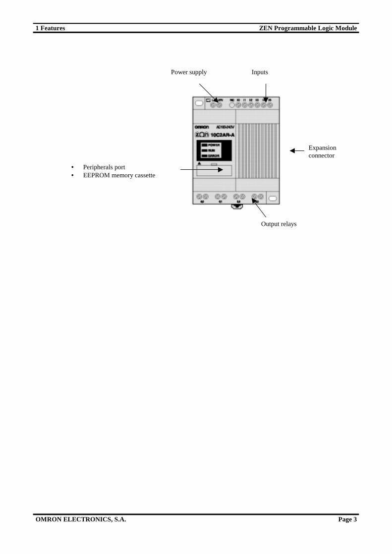
1 Features ZEN Programmable Logic Module
OMRON ELECTRONICS, S.A. Page 3
Output relays
Expansionconnector
• Peripherals port• EEPROM memory cassette
InputsPower supply

2 Functionality ZEN Programmable Logic Module
OMRON ELECTRONICS, S.A. Page 4
2. Functionality
The display screen for the LCD type CPU and the different ZEN operationbuttons are as follows:
A series of icons giving information about the controller can be activated in thedisplay. The meaning of these icons is given in the following table:
Icon MeaningRUN Displayed on screen when in RUN modeERR Shows an error "
Displayed on screen when there is a higher level on the menu orin the ladder program
#Displayed on screen when there is a lower level on the menu or inthe ladder programDisplayed on screen when the password has been activated
Function keypad
FunctionKeyMenu Overwriting the program Parameter Settings Associated
bitDEL --- Deletes inputs, outputs,
connection lines and blank lines--- B6 to ON
ALT --- Switchs to normally open andnormally closed conditions.
--- B7 to ON
Up B5 to ONDown
Moves thecursor up anddown
Moves the cursor up and down.Selects bit types and functions.
Moves the cursor up and down.Changes numerals andparameters
B2 to ON
Left B3 to ONRight
--- Moves the cursor to the rightand left
Moves the cursor to the rightand left B4 to ON
ESC Returns toprevious screen
Cancels operations carried outand returns to the previousoperation
Cancels operations carried outand returns to the previousoperation
B0 to ON
OK Enters themenu selected
Confirms the settings Confirms the settings B1 to ON
LCD
DEL button
ESC button
ALT button
OK button
3 Handling the Equipment ZEN Programmable Logic Module
OMRON ELECTRONICS, S.A. Page 5
3. Handling the Equipment
This section describes the handling of the display menu and its differentoptions, such as protecting ladder programs, installing filters on inputs,adjusting the display contrast, setting the clock to summer time, etc.
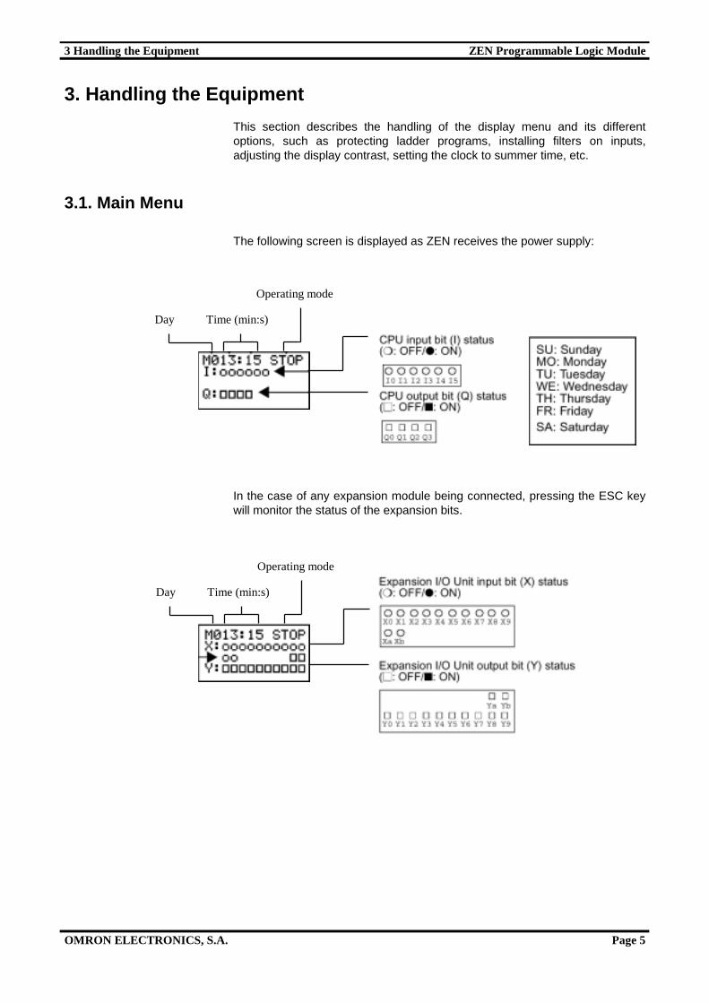
3.1. Main Menu
The following screen is displayed as ZEN receives the power supply:
In the case of any expansion module being connected, pressing the ESC keywill monitor the status of the expansion bits.
Day Time (min:s)
Operating mode
Day Time (min:s)
Operating mode
3 Handling the Equipment ZEN Programmable Logic Module
OMRON ELECTRONICS, S.A. Page 6
The main menu is displayed by pressing the OK key on the initial screen, asshown below:
3.2. Selecting the Language
The ZEN menu is available in 6 languages, which can be selected as follows(the default language is English)
3.3. Date and Time
Access to the date and time settings window can be gained by following themenu sequence shown below:
The Up/Down keys switch from themenu window to other options.
Select LANGUAGE and press OK. By doing this,the language selection screen is displayed and bypressing the OK key again, the language flashes,making it possible to select another languageusing the cursors.
Once the language has been selected, press OKand this confirmation window will appear.
3 Handling the Equipment ZEN Programmable Logic Module
OMRON ELECTRONICS, S.A. Page 7
3.4. Protecting Programs
ZEN has a password function, used to prevent incorrect use of the ladderprogram or to prevent manipulation of settings made by the controller.
The password code may comprise the range 0000 to 9999 (4 decimalnumbers).
The password prevents entry to the following points:
• Editing ladder programs• Monitorng ladder programs• Changing or erasing the password• Setting the input filter• Setting the node number
The Password screen is displayed immediately any of the different options isselected from the menu. If the password is correct, access to the screenrequested will be given. If not, access will be denied.
3.5. Setting a Password
Select OTHER on the main menu and then thePASSWORD option.
Press the OK key so that the cursor flashes andthe password can then be entered
Set the Password.Use the Left and Right keys to select thedigits that need to be changed.Use the Up/Down keys to enter numbersfrom 0 to 9.
Press the OK key. A confirmation messagewill be displayed on the screen
The key symbol will be displayed in thebottom left-hand corner of the screen whenthe password has been recorded.
3 Handling the Equipment ZEN Programmable Logic Module
OMRON ELECTRONICS, S.A. Page 8
3.6. Deleting Registered Passwords
3.7. Stabilizing Input Operations
If the ZEN external input fluctuates, it is possible that the operations will beunstable. To solve this, ZEN is able to filter inputs to stablilize the signal.
The input filters can be set separately, either for the CPU inputs or for eachI/O expansion unit.
Press the OK key so that the cursor flashesand then enter the password.
Enter the recorded password.
Use the Left and Right keys to change thenumbers of the new passwordUse the Up/Down keys to enter numbersbetween 0 to 9.
Press the OK key to display the message onscreen confirming deletion of the password.If the input password does not match to theoriginal, the display will return to theprevious screen.If the password is correct, press the OK keyto delete.
They key icon will disappear when thepassword has been deleted.
If the input password does not match to therecorded password, a ‘CHECK ERR’message will appear on screen. Thepassword must be reentered.
3 Handling the Equipment ZEN Programmable Logic Module
OMRON ELECTRONICS, S.A. Page 9
Note. The input filter time settings are as follows:
Input specifications Input filternot used
Input filterused
100 Vac 50 ms 70 msAC Input240 Vac 100 ms 120 ms
DC Input 15 ms 50 ms
The input filter settings are read when ZEN starts the operation.
3.8. Backlight
The LCD backlight is automatically activated when the operation keys areused. Depending on the setting (see below for more details), this light willswitch itself off 2, 10 or 30 minutes after the function keys have stopped beingused. The backlight can also be left activated (setting always in ON mode).
Press the OK key to display the inputfilter setting menu.
Use the Up/Down keys to select fromthe Menu the unit for which the inputfilters will be set.
Press the OK key twice to make thecursor flash, activating the input filter.
Use the Up/Down keys to switchbetween ON/FF.
Press ON to confirm the settings.Press ON again to complete thesettings.

3 Handling the Equipment ZEN Programmable Logic Module
OMRON ELECTRONICS, S.A. Page 10
3.9. Adjusting LCD Screen Contrast
Use the following procedure to adjust the LCD contrast when it is difficult toview the screens.
Press the OK key to view the currentcontrast setting. This will be displayed inthe form of a bar graph (5 levels).A blank level shows that this setting hasnot been reached.
Press the OK key again to a flashing cursorto vary the contrast. The contrast settingcan be changed using the Up/Down orRight/Left keys.
Pressing the OK key once again requestsconfirmation of the new setting. If pressed,it will be confirmed. Pressing the ESC keywill exit the Contrast Menu with nochanges being made.
Press the OK key to display the currentbacklight time.
Press the OK key again to a flashingcursor to change this time.
Use the Up/Down keys to selectactivation time.
Press the OK key to confirm thesettings. Press again to completethe settings.
3 Handling the Equipment ZEN Programmable Logic Module
OMRON ELECTRONICS, S.A. Page 11
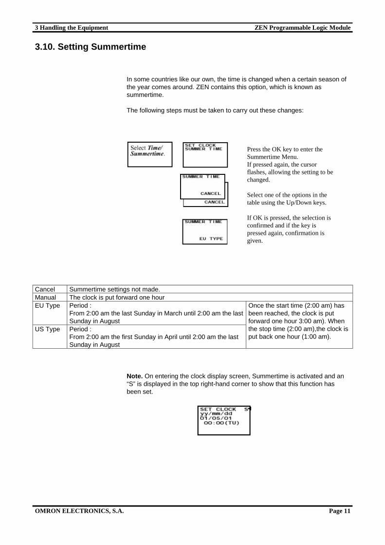
3.10. Setting Summertime
In some countries like our own, the time is changed when a certain season ofthe year comes around. ZEN contains this option, which is known assummertime.
The following steps must be taken to carry out these changes:
Cancel Summertime settings not made.Manual The clock is put forward one hourEU Type Period :
From 2:00 am the last Sunday in March until 2:00 am the lastSunday in August
US Type Period :From 2:00 am the first Sunday in April until 2:00 am the lastSunday in August
Once the start time (2:00 am) hasbeen reached, the clock is putforward one hour 3:00 am). Whenthe stop time (2:00 am),the clock isput back one hour (1:00 am).
Note. On entering the clock display screen, Summertime is activated and an“S” is displayed in the top right-hand corner to show that this function hasbeen set.
Press the OK key to enter theSummertime Menu.If pressed again, the cursorflashes, allowing the setting to bechanged.
Select one of the options in thetable using the Up/Down keys.
If OK is pressed, the selection isconfirmed and if the key ispressed again, confirmation isgiven.
3 Handling the Equipment ZEN Programmable Logic Module
OMRON ELECTRONICS, S.A. Page 12
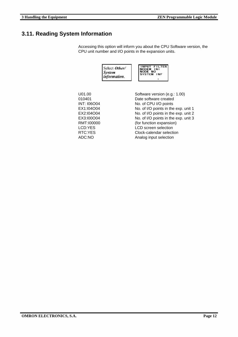
3.11. Reading System Information
Accessing this option will inform you about the CPU Software version, theCPU unit number and I/O points in the expansion units.
U01.00 Software version (e.g.: 1.00)010401 Date software createdINT: I06O04 No. of CPU I/O pointsEX1:I04O04 No. of I/O points in the exp. unit 1EX2:I04O04 No. of I/O points in the exp. unit 2EX3:I00O04 No. of I/O points in the exp. unit 3RMT:I00000 (for function expansion)LCD:YES LCD screen selectionRTC:YES Clock-calendar selectionADC:NO Analog input selection
4 Connections ZEN Programmable Logic Module
OMRON ELECTRONICS, S.A. Page 13
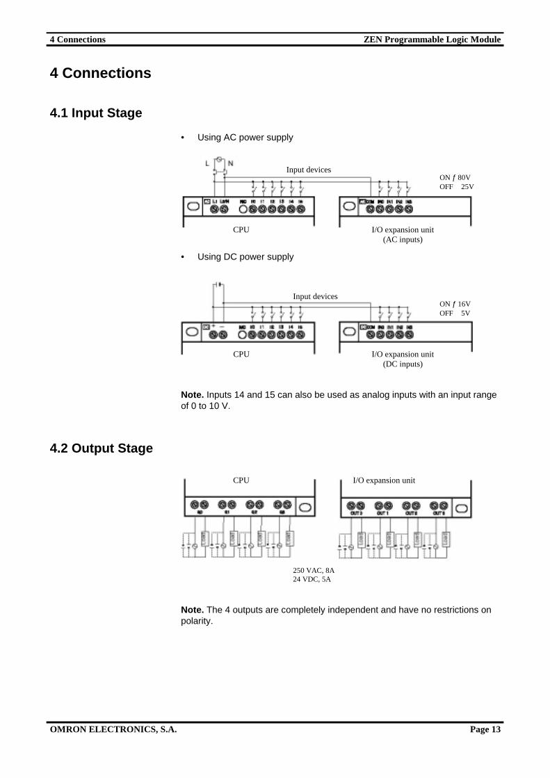
4 Connections
4.1 Input Stage
• Using AC power supply
• Using DC power supply
Note. Inputs 14 and 15 can also be used as analog inputs with an input rangeof 0 to 10 V.
4.2 Output Stage
Note. The 4 outputs are completely independent and have no restrictions onpolarity.
I/O expansion unitCPU
I/O expansion unit(AC inputs)
CPU
Input devices
I/O expansion unit(DC inputs)
CPU
Input devices
250 VAC, 8A24 VDC, 5A
ON ƒ 16VOFF 5V
ON ƒ 80VOFF 25V
5 I/O Addressing ZEN Programmable Logic Module
OMRON ELECTRONICS, S.A. Page 14
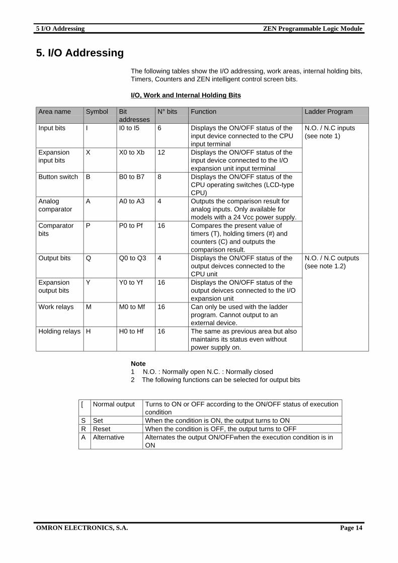
5. I/O Addressing
The following tables show the I/O addressing, work areas, internal holding bits,Timers, Counters and ZEN intelligent control screen bits.
I/O, Work and Internal Holding Bits
Area name Symbol Bitaddresses
N° bits Function Ladder Program
Input bits I I0 to I5 6 Displays the ON/OFF status of theinput device connected to the CPUinput terminal
Expansioninput bits
X X0 to Xb 12 Displays the ON/OFF status of theinput device connected to the I/Oexpansion unit input terminal
Button switch B B0 to B7 8 Displays the ON/OFF status of theCPU operating switches (LCD-typeCPU)
Analogcomparator
A A0 to A3 4 Outputs the comparison result foranalog inputs. Only available formodels with a 24 Vcc power supply.
Comparatorbits
P P0 to Pf 16 Compares the present value oftimers (T), holding timers (#) andcounters (C) and outputs thecomparison result.
N.O. / N.C inputs(see note 1)
Output bits Q Q0 to Q3 4 Displays the ON/OFF status of theoutput deivces connected to theCPU unit
Expansionoutput bits
Y Y0 to Yf 16 Displays the ON/OFF status of theoutput deivces connected to the I/Oexpansion unit
Work relays M M0 to Mf 16 Can only be used with the ladderprogram. Cannot output to anexternal device.
Holding relays H H0 to Hf 16 The same as previous area but alsomaintains its status even withoutpower supply on.
N.O. / N.C outputs(see note 1.2)
Note1 N.O. : Normally open N.C. : Normally closed2 The following functions can be selected for output bits
[ Normal output Turns to ON or OFF according to the ON/OFF status of executioncondition
S Set When the condition is ON, the output turns to ONR Reset When the condition is OFF, the output turns to OFFA Alternative Alternates the output ON/OFFwhen the execution condition is in
ON
5 I/O Addressing ZEN Programmable Logic Module
OMRON ELECTRONICS, S.A. Page 15
Timers and Counters
Area name Symbol Bitaddresses
N° bits Function Ladder Program
Timer T T0 to T7 8 Can be activated between ON-delay,OFF-delay, one-shot and flashingpulse operation.
Holdingtimer
# #0 to #3 4 Maintains the timer value when thetrigger input is in OFF mode. Thetimer will continue even if turned toON mode again.
Clocktimer
@ @0 to @7 8 Can be put into ON or OFF mode ona specified day or period.
Calendartimer
* *0 to *7 8 Can be put into ON or OFF mode ona specified date.
Counter C C0 to C7 8 Reversible counter
N.O. / N. C condition(see note 1)
Note Timers can have the following functions.
X ON delay Time elapsed from the moment the input is triggered until the set timer bitturns to ON mode.
n OFF delay The timer bit turns to ON mode from the moment the input is triggereduntil the set time has elapsed on the timer.
O One-shot The set timer bit turns the selected time to ON mode when the triggerinput switches from OFF to ON mode.
F Flashing pulse The set timer bit constantly switches from OFF to ON mode while thetrigger input remains in ON mode
Display Bits
Areaname
Symbol Bitaddresses
N° bits Function Ladder Program
Display D D0 to D7 8 Displays predefined messages relating totimers, counters and their present values orconverted analog values.
Output
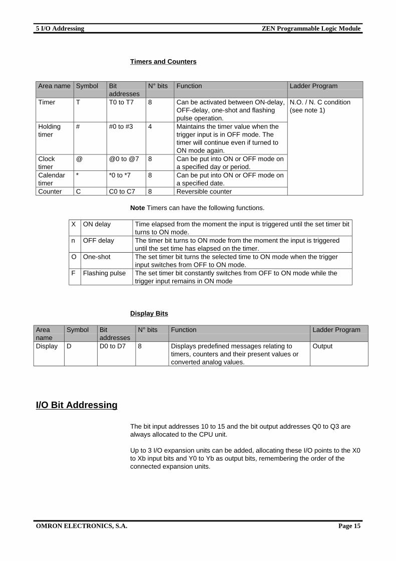
I/O Bit Addressing
The bit input addresses 10 to 15 and the bit output addresses Q0 to Q3 arealways allocated to the CPU unit.
Up to 3 I/O expansion units can be added, allocating these I/O points to the X0to Xb input bits and Y0 to Yb as output bits, remembering the order of theconnected expansion units.
5 I/O Addressing ZEN Programmable Logic Module
OMRON ELECTRONICS, S.A. Page 16
Note
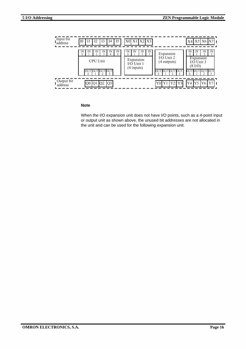
When the I/O expansion unit does not have I/O points, such as a 4-point inputor output unit as shown above, the unused bit addresses are not allocated inthe unit and can be used for the following expansion unit.
6 Creating the Program ZEN Programmable Logic Module
OMRON ELECTRONICS, S.A. Page 17
6. Creating the Program
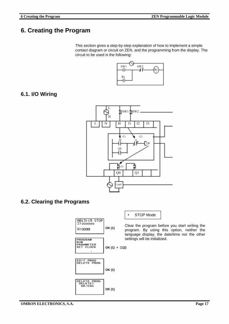
This section gives a step-by-step explanation of how to implement a simplecontact diagram or circuit on ZEN, and the programming from the display. Thecircuit to be used is the following:
6.1. I/O Wiring
6.2. Clearing the Programs
Clear the program before you start writing theprogram. By using this option, neither thelanguage display, the date/time nor the othersettings will be initialized.
OK (1)
OK (1) + ⇓⇓⇓⇓ (2)
OK (1)
OK (1)
• STOP Mode
6 Creating the Program ZEN Programmable Logic Module
OMRON ELECTRONICS, S.A. Page 18
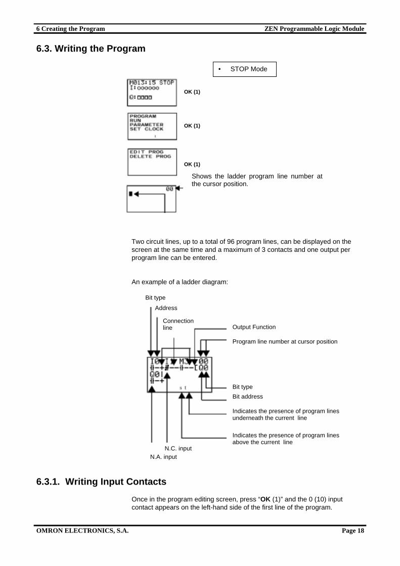
6.3. Writing the Program
Two circuit lines, up to a total of 96 program lines, can be displayed on thescreen at the same time and a maximum of 3 contacts and one output perprogram line can be entered.
An example of a ladder diagram:
6.3.1. Writing Input Contacts
Once in the program editing screen, press “OK (1)” and the 0 (10) inputcontact appears on the left-hand side of the first line of the program.
• STOP Mode
OK (1)
OK (1)
OK (1)
Shows the ladder program line number atthe cursor position.
Bit type
Address
Output Function
Program line number at cursor position
Connectionline
Bit type
Bit address
Indicates the presence of program linesunderneath the current line
Indicates the presence of program linesabove the current line
N.C. inputN.A. input
6 Creating the Program ZEN Programmable Logic Module
OMRON ELECTRONICS, S.A. Page 19
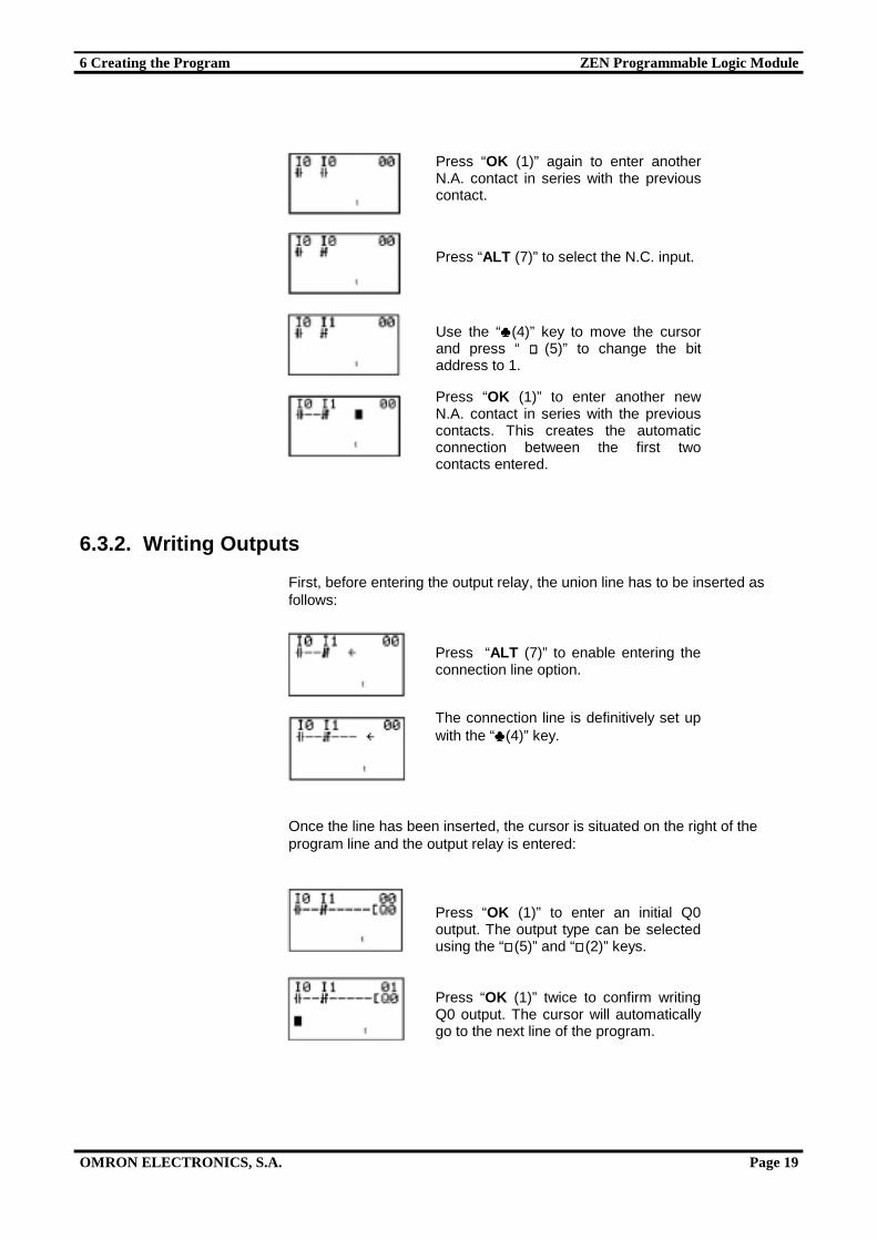
6.3.2. Writing Outputs
First, before entering the output relay, the union line has to be inserted asfollows:
Once the line has been inserted, the cursor is situated on the right of theprogram line and the output relay is entered:
Press “ALT (7)” to select the N.C. input.
Use the “♣♣♣♣(4)” key to move the cursorand press “ ⇑⇑⇑⇑ (5)” to change the bitaddress to 1.
Press “OK (1)” again to enter anotherN.A. contact in series with the previouscontact.
Press “OK (1)” to enter another newN.A. contact in series with the previouscontacts. This creates the automaticconnection between the first twocontacts entered.
Press “ALT (7)” to enable entering theconnection line option.
The connection line is definitively set upwith the “♣♣♣♣(4)” key.
Press “OK (1)” to enter an initial Q0output. The output type can be selectedusing the “⇑⇑⇑⇑ (5)” and “⇓⇓⇓⇓ (2)” keys.
Press “OK (1)” twice to confirm writingQ0 output. The cursor will automaticallygo to the next line of the program.
6 Creating the Program ZEN Programmable Logic Module
OMRON ELECTRONICS, S.A. Page 20
6.3.3. Writing a Parallel Line (OR)
6.3.4. Vertical Connection Lines
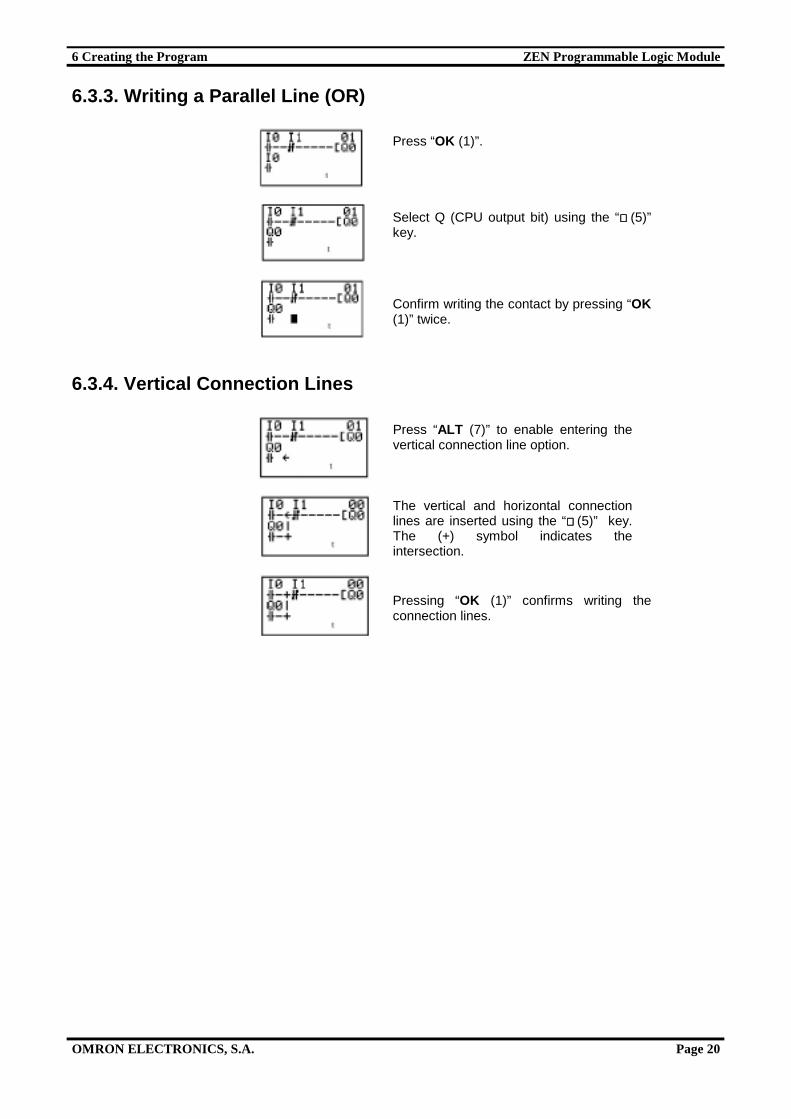
Press “OK (1)”.
Select Q (CPU output bit) using the “⇑⇑⇑⇑ (5)”key.
Confirm writing the contact by pressing “OK(1)” twice.
Press “ALT (7)” to enable entering thevertical connection line option.
The vertical and horizontal connectionlines are inserted using the “⇑⇑⇑⇑ (5)” key.The (+) symbol indicates theintersection.
Pressing “OK (1)” confirms writing theconnection lines.
7 Programming Functions ZEN Programmable Logic Module
OMRON ELECTRONICS, S.A. Page 21
7. Programming Functions
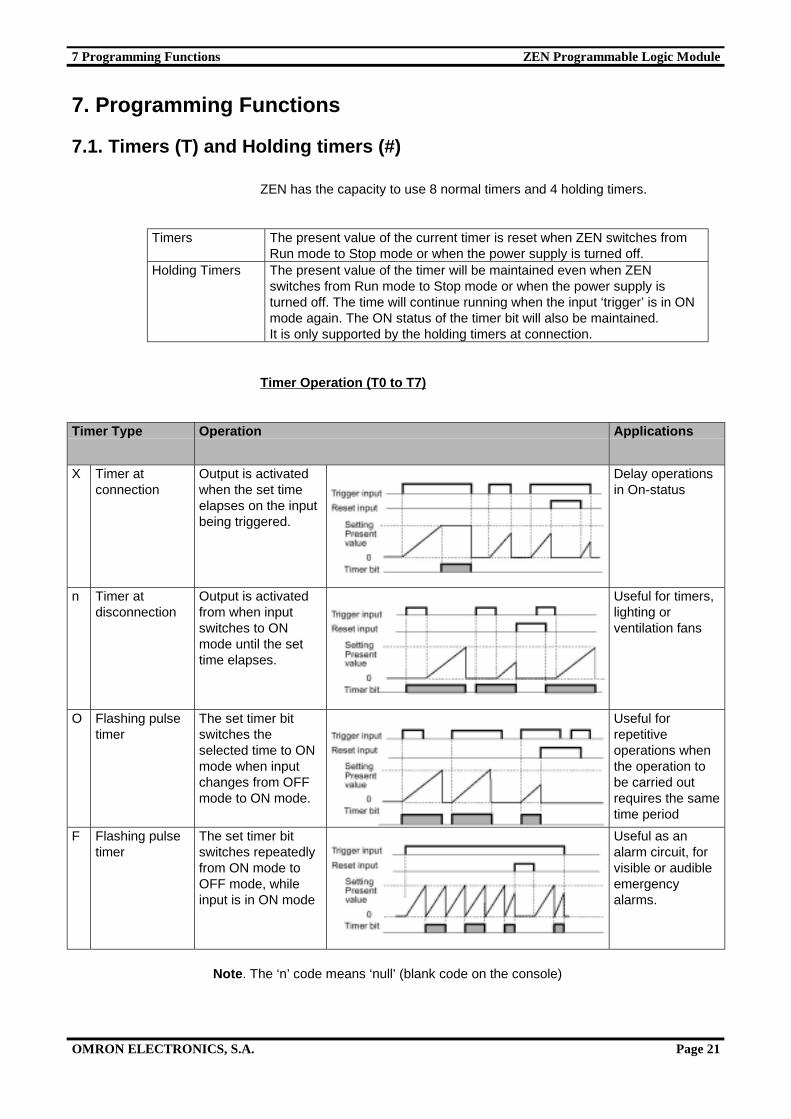
7.1. Timers (T) and Holding timers (#)
ZEN has the capacity to use 8 normal timers and 4 holding timers.
Timers The present value of the current timer is reset when ZEN switches fromRun mode to Stop mode or when the power supply is turned off.
Holding Timers The present value of the timer will be maintained even when ZENswitches from Run mode to Stop mode or when the power supply isturned off. The time will continue running when the input ‘trigger’ is in ONmode again. The ON status of the timer bit will also be maintained.It is only supported by the holding timers at connection.
Timer Operation (T0 to T7)
Timer Type Operation Applications
X Timer atconnection
Output is activatedwhen the set timeelapses on the inputbeing triggered.
Delay operationsin On-status
n Timer atdisconnection
Output is activatedfrom when inputswitches to ONmode until the settime elapses.
Useful for timers,lighting orventilation fans
O Flashing pulsetimer
The set timer bitswitches theselected time to ONmode when inputchanges from OFFmode to ON mode.
Useful forrepetitiveoperations whenthe operation tobe carried outrequires the sametime period
F Flashing pulsetimer
The set timer bitswitches repeatedlyfrom ON mode toOFF mode, whileinput is in ON mode
Useful as analarm circuit, forvisible or audibleemergencyalarms.
Note. The ‘n’ code means ‘null’ (blank code on the console)
7 Programming Functions ZEN Programmable Logic Module
OMRON ELECTRONICS, S.A. Page 22
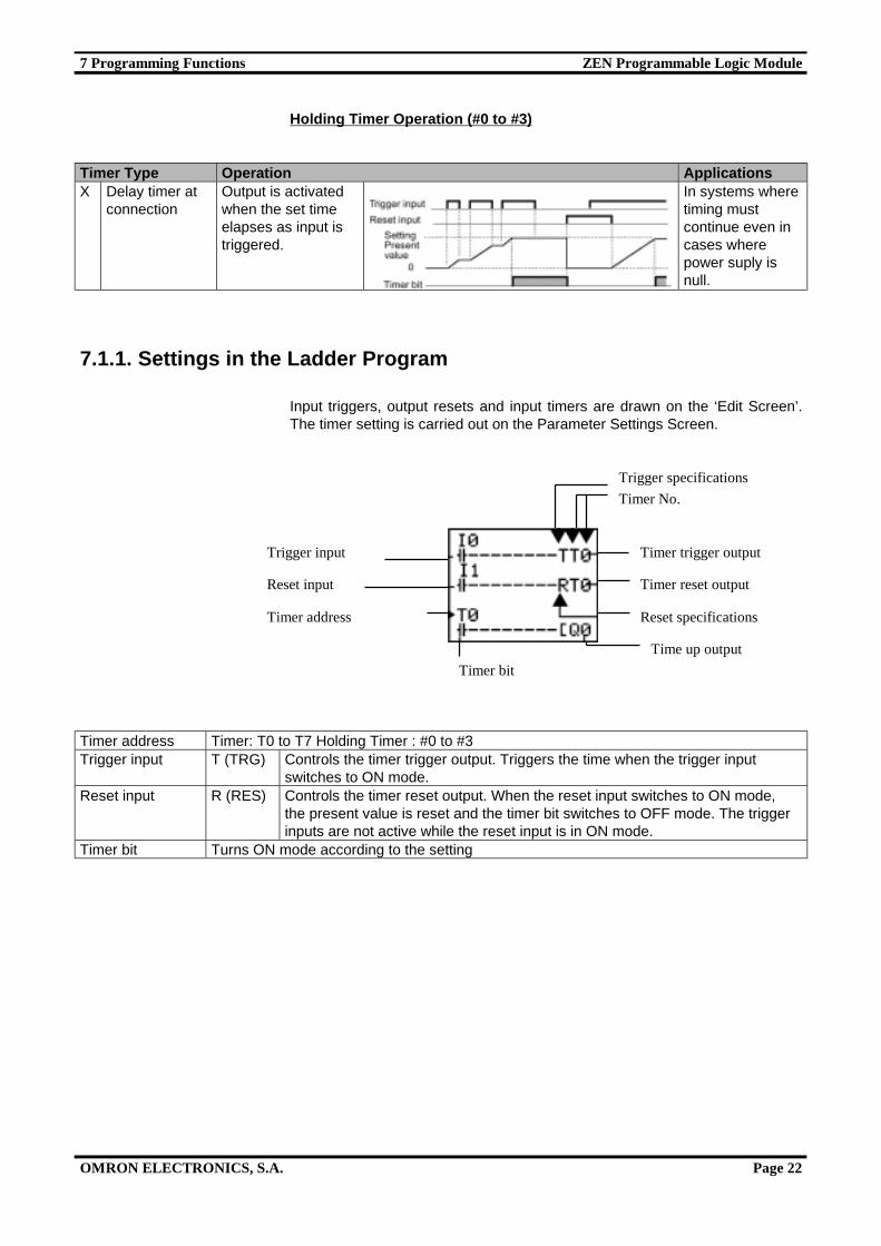
Holding Timer Operation (#0 to #3)
Timer Type Operation ApplicationsX Delay timer at
connectionOutput is activatedwhen the set timeelapses as input istriggered.
In systems wheretiming mustcontinue even incases wherepower suply isnull.
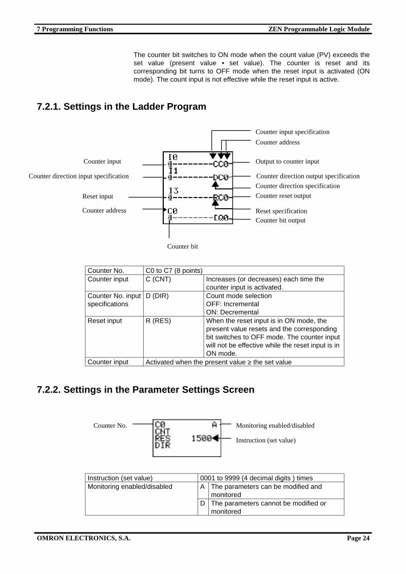
7.1.1. Settings in the Ladder Program
Input triggers, output resets and input timers are drawn on the ‘Edit Screen’.The timer setting is carried out on the Parameter Settings Screen.
Timer address Timer: T0 to T7 Holding Timer : #0 to #3Trigger input T (TRG) Controls the timer trigger output. Triggers the time when the trigger input
switches to ON mode.Reset input R (RES) Controls the timer reset output. When the reset input switches to ON mode,
the present value is reset and the timer bit switches to OFF mode. The triggerinputs are not active while the reset input is in ON mode.
Timer bit Turns ON mode according to the setting
Trigger specifications
Timer No.
Reset specifications
Time up output
Timer reset output
Timer trigger outputTrigger input
Reset input
Timer address
Timer bit
7 Programming Functions ZEN Programmable Logic Module
OMRON ELECTRONICS, S.A. Page 23
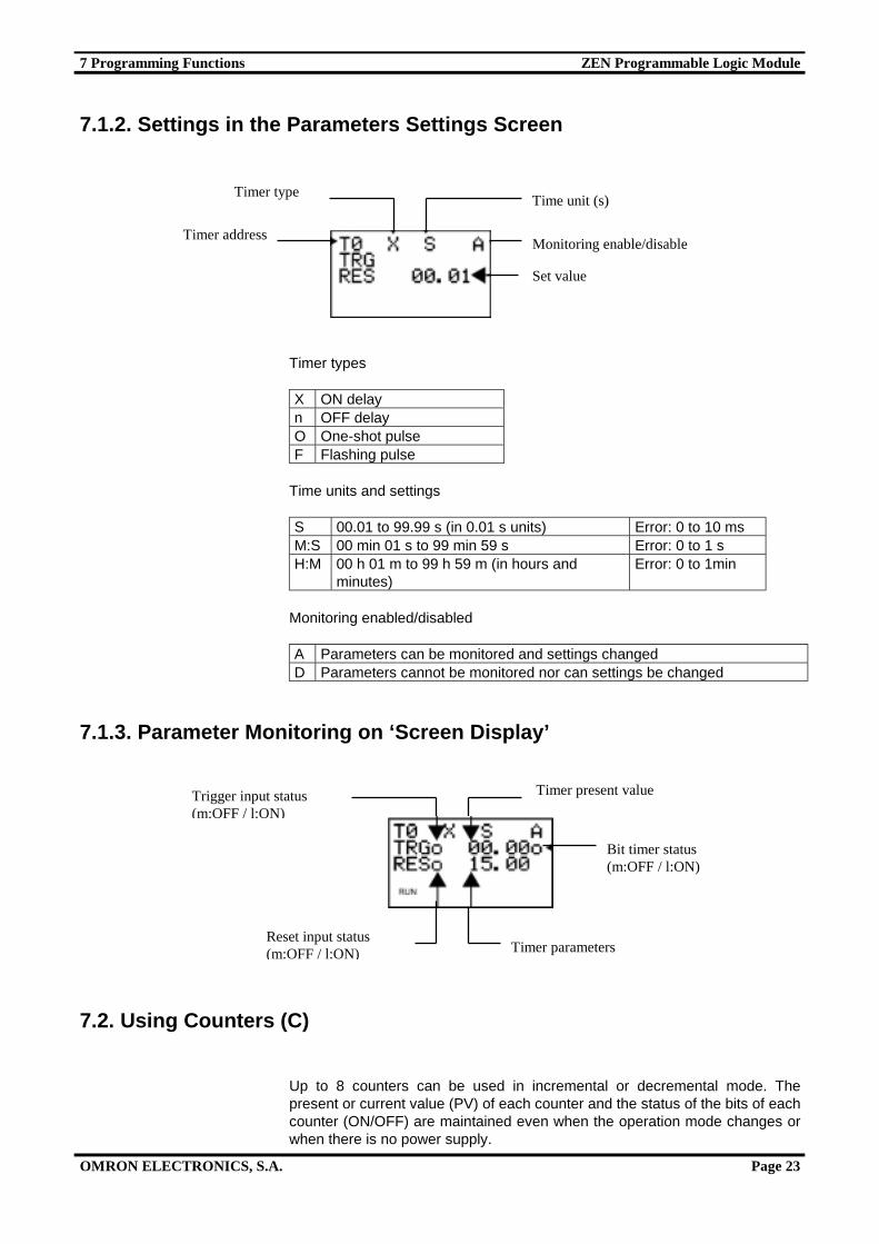
7.1.2. Settings in the Parameters Settings Screen
Timer types
X ON delayn OFF delayO One-shot pulseF Flashing pulse
Time units and settings
S 00.01 to 99.99 s (in 0.01 s units) Error: 0 to 10 msM:S 00 min 01 s to 99 min 59 s Error: 0 to 1 sH:M 00 h 01 m to 99 h 59 m (in hours and
minutes)Error: 0 to 1min
Monitoring enabled/disabled
A Parameters can be monitored and settings changedD Parameters cannot be monitored nor can settings be changed
7.1.3. Parameter Monitoring on ‘Screen Display’
7.2. Using Counters (C)
Up to 8 counters can be used in incremental or decremental mode. Thepresent or current value (PV) of each counter and the status of the bits of eachcounter (ON/OFF) are maintained even when the operation mode changes orwhen there is no power supply.
Time unit (s)
Monitoring enable/disable
Timer type
Timer parametersReset input status(m:OFF / l:ON)
Trigger input status(m:OFF / l:ON)
Timer present value
Set value
Timer address
Bit timer status(m:OFF / l:ON)
7 Programming Functions ZEN Programmable Logic Module
OMRON ELECTRONICS, S.A. Page 24
The counter bit switches to ON mode when the count value (PV) exceeds theset value (present value • set value). The counter is reset and itscorresponding bit turns to OFF mode when the reset input is activated (ONmode). The count input is not effective while the reset input is active.
7.2.1. Settings in the Ladder Program
Counter No. C0 to C7 (8 points)Counter input C (CNT) Increases (or decreases) each time the
counter input is activated.Counter No. inputspecifications
D (DIR) Count mode selectionOFF: IncrementalON: Decremental
Reset input R (RES) When the reset input is in ON mode, thepresent value resets and the correspondingbit switches to OFF mode. The counter inputwill not be effective while the reset input is inON mode.
Counter input Activated when the present value ≥ the set value
7.2.2. Settings in the Parameter Settings Screen
Instruction (set value) 0001 to 9999 (4 decimal digits ) timesA The parameters can be modified and
monitoredMonitoring enabled/disabled
D The parameters cannot be modified ormonitored
Counter address
Counter input specification
Output to counter input
Counter direction specification
Counter direction output specification
Counter reset output
Reset specificationCounter bit output
Counter bit
Counter address
Reset input
Counter input
Counter direction input specification
Monitoring enabled/disabled
Instruction (set value)
Counter No.
7 Programming Functions ZEN Programmable Logic Module
OMRON ELECTRONICS, S.A. Page 25
7.2.3. Parameter Monitoring on the Screen Display
Note.
1. To reset the present value and the counter bit status (ON/OFF mode) dueto a power supply fault or a change in operating mode, a reset circuit mustbe created which should be activated first. This circuit may be somethinglike the following:
2. If the counter input and the counter direction are input simultaneously,place the counter direction output in the program before the counter input.
7.3. Using Weekly Timers
Weekly timers switch to ON mode between the start time and the end of thespecified day. Weekly timers have 8 points (@0 to @7).
Counter reset output
Counter direction outputspecification
Output to counter input
Counter presentvalue
Counter bit status(l:ON/m:OFF)
Counter input status(m:OFF/l:ON)
Counter No. input statusspecification (m:OFF/l:ON)
Reset input status(m:OFF/l:ON)
Instruction (setvalue)
7 Programming Functions ZEN Programmable Logic Module
OMRON ELECTRONICS, S.A. Page 26
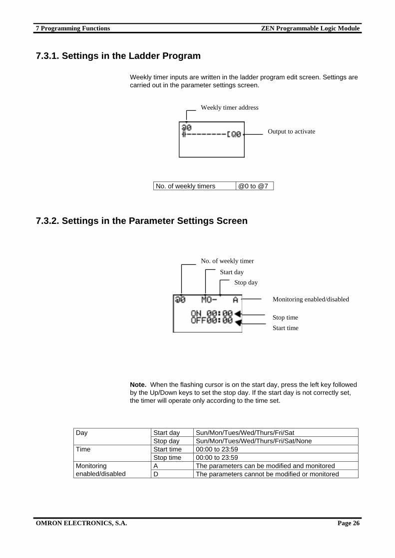
7.3.1. Settings in the Ladder Program
Weekly timer inputs are written in the ladder program edit screen. Settings arecarried out in the parameter settings screen.
No. of weekly timers @0 to @7
7.3.2. Settings in the Parameter Settings Screen
Note. When the flashing cursor is on the start day, press the left key followedby the Up/Down keys to set the stop day. If the start day is not correctly set,the timer will operate only according to the time set.
Start day Sun/Mon/Tues/Wed/Thurs/Fri/SatDayStop day Sun/Mon/Tues/Wed/Thurs/Fri/Sat/NoneStart time 00:00 to 23:59TimeStop time 00:00 to 23:59A The parameters can be modified and monitoredMonitoring
enabled/disabled D The parameters cannot be modified or monitored
Weekly timer address
Output to activate
No. of weekly timer
Start day
Stop day
Monitoring enabled/disabled
Start time
Stop time
7 Programming Functions ZEN Programmable Logic Module
OMRON ELECTRONICS, S.A. Page 27
Setup and operation Example OperationWhen the start day isbefore the stop day
MO - FR Operates Monday toFriday every week
When the start day isafter the stop day
FR - MO Operates every Fridaythrough to the followingMonday
When the start day is thesame as the stop day
SU - SU Operates regardless of theday of the week
Start and stopdays
When the stop day is notset
SU - Operates only everySunday
When the start time isbefore the stop time
ON: 08:00OFF: 17:00
Operates from 8:00 to17:00 every day
When the start time isafter the stop time
ON: 21:00OFF: 06:00
Operates from 21:00 to6:00 the following day
Start and stoptimes
When the start time is thesame as the stop time
ON: 13:00OFF: 13:00
Operates regardless of thetime
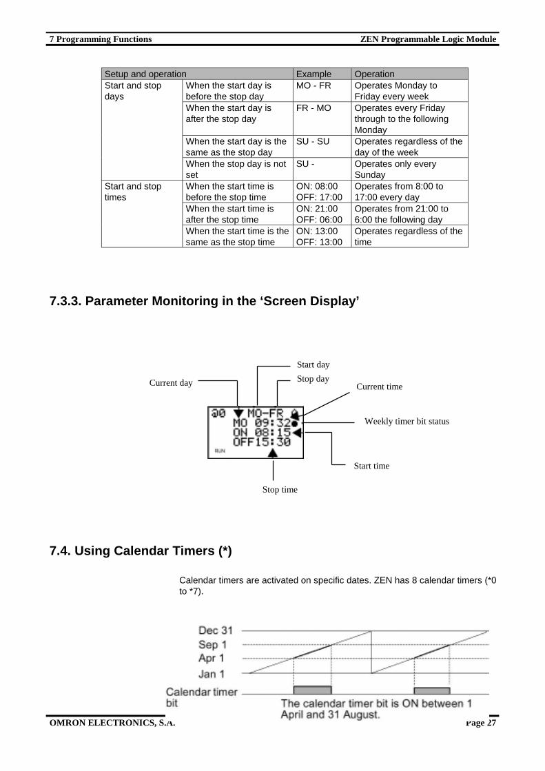
7.3.3. Parameter Monitoring in the ‘Screen Display’
7.4. Using Calendar Timers (*)
Calendar timers are activated on specific dates. ZEN has 8 calendar timers (*0to *7).
Current day
Start day
Stop dayCurrent time
Weekly timer bit status
Start time
Stop time
7 Programming Functions ZEN Programmable Logic Module
OMRON ELECTRONICS, S.A. Page 28
7.4.1. Settings in the Ladder Program
Calendar timer inputs are written in the ‘Edit Screen’. Settings are carried outin the parameter settings screen.
No. of Calendar Timer *0 to *7
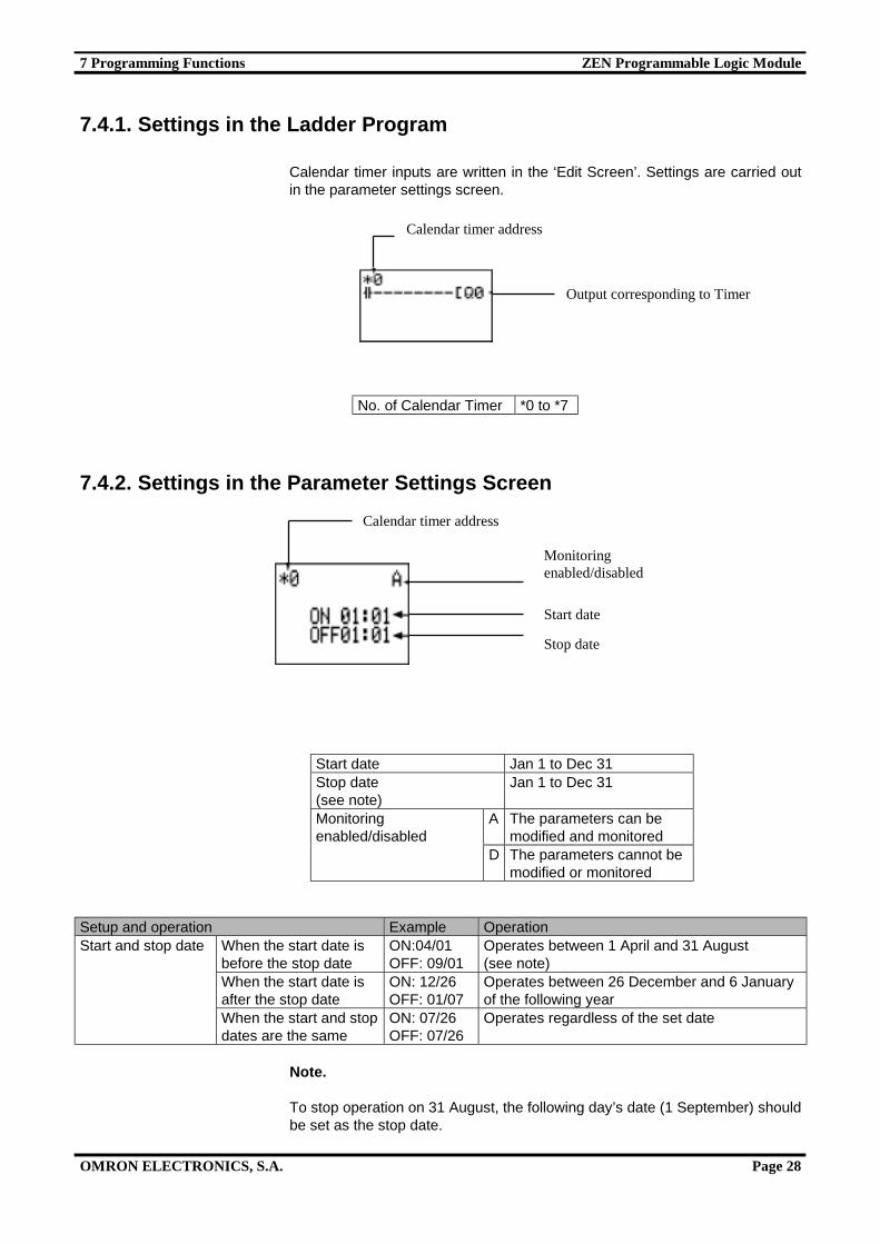
7.4.2. Settings in the Parameter Settings Screen
Start date Jan 1 to Dec 31Stop date(see note)
Jan 1 to Dec 31
A The parameters can bemodified and monitored
Monitoringenabled/disabled
D The parameters cannot bemodified or monitored
Setup and operation Example OperationWhen the start date isbefore the stop date
ON:04/01OFF: 09/01
Operates between 1 April and 31 August(see note)
When the start date isafter the stop date
ON: 12/26OFF: 01/07
Operates between 26 December and 6 Januaryof the following year
Start and stop date
When the start and stopdates are the same
ON: 07/26OFF: 07/26
Operates regardless of the set date
Note.
To stop operation on 31 August, the following day’s date (1 September) shouldbe set as the stop date.
Calendar timer address
Output corresponding to Timer
Calendar timer address
Monitoringenabled/disabled
Start date
Stop date
7 Programming Functions ZEN Programmable Logic Module
OMRON ELECTRONICS, S.A. Page 29
7.4.3. Parameter Monitoring in the ‘Screen Display’
7.5. Analog Inputs (Analog Comparator (A))
Analog voltage inputs vary between 0 and 10 V. ZEN has 2 analog inputpoints, I4 and I5.
The analog input signal is converted into a BCD value (00.0 to 10.0). Theresult can be used in one of the CPU comparators, A0 to A3, and the 4comparison outputs can be used in the program as input conditions.
7.5.1. Settings in the Ladder Program
The analog comparator input is written in the ladder program edit screen. Thesettings are carried out in the parameter settings screen.
No. of analog comparator A0 to A3
Current date
Start date
Stop date
Calendar timer bit status(m:OFF/l:ON)
(0.0 to 10.0 V)
Comparison resultoutputAnalog comparator bit
7 Programming Functions ZEN Programmable Logic Module
OMRON ELECTRONICS, S.A. Page 30
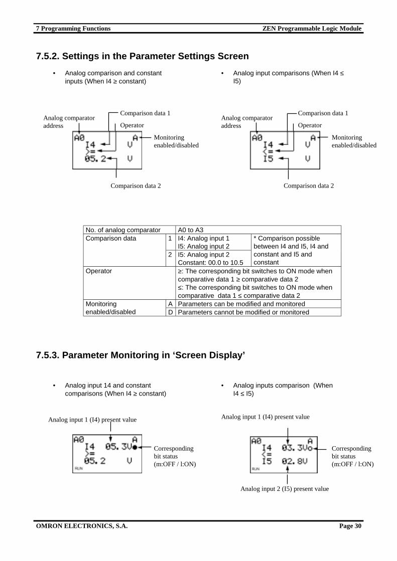
7.5.2. Settings in the Parameter Settings Screen
No. of analog comparator A0 to A31 I4: Analog input 1
I5: Analog input 2Comparison data
2 I5: Analog input 2Constant: 00.0 to 10.5
* Comparison possiblebetween I4 and I5, I4 andconstant and I5 andconstant
Operator ≥: The corresponding bit switches to ON mode whencomparative data 1 ≥ comparative data 2≤: The corresponding bit switches to ON mode whencomparative data 1 ≤ comparative data 2
A Parameters can be modified and monitoredMonitoringenabled/disabled D Parameters cannot be modified or monitored
7.5.3. Parameter Monitoring in ‘Screen Display’
• Analog input comparisons (When I4 ≤I5)
Analog comparatoraddress
Comparison data 1
Operator
Comparison data 2
Monitoringenabled/disabled
Analog comparatoraddress
Comparison data 1
Operator
Comparison data 2
Monitoringenabled/disabled
• Analog input 14 and constantcomparisons (When I4 ≥ constant)
• Analog inputs comparison (WhenI4 ≤ I5)
Analog input 1 (I4) present value
Correspondingbit status(m:OFF / l:ON)
Analog input 1 (I4) present value
Correspondingbit status(m:OFF / l:ON)
Analog input 2 (I5) present value
• Analog comparison and constantinputs (When I4 ≥ constant)
7 Programming Functions ZEN Programmable Logic Module
OMRON ELECTRONICS, S.A. Page 31
7.6. Comparing Timer/Counter Present Values Using Comparators (P)
Timer (T), holding timer (#) and counter (C) present values can be compared.Present values of the same type of timers or counters can be compared. Theycan also be compared with constants.
7.6.1. Settings in the Ladder Program
The comparator inputs are written in the ladder program edit screen. Thesettings are carried out in the parameter settings screen.
No. of comparators P0 to P5
• Example 1When the holding timer #0 ≥ 12 min 34 s
• Example 2When counter 1 (C1) ≤ counter 2 (C2)
Associated bit
Output asresult of theoperation
7 Programming Functions ZEN Programmable Logic Module
OMRON ELECTRONICS, S.A. Page 32
7.6.2. Settings in the Parameter Settings Screen
Comparison type T: Timer#: Holding timerC: Counter
1 T: T0 toT7#: #0 to #3C: C0 to C7
Comparison data
2 T: T0 to T7#: #0 to #3C: C0 to C7Constant: 00.00 to 99.99 when thecomparison type is T / #.0000 to 9999 when the comparison typeis C
Comparison possible between Tand T or T and the constantComparison possible between #and # or # and the constantComparison possible between Cand C or C and the constant
≥: The corresponding timer/counter bit switches to ON mode whendata1≥data2
Operator
≤: The corresponding timer/counter bit switches to ON mode whendata1≤data2
A The parameters can be modified and monitoredMonitoringenabled/disabled D The parameters cannot be modified or monitored
Note. To enter the data as constant, press ALT.
7.6.3. Parameter Monitoring in the ‘Screen Display’
• Comparison of holding and constanttimers (When the holding timer #0 ≥12 min 34 s)
• Comparison of counters (When counter1 (C1) ≤ counter 2 (C2)
• Comparison of holding timer #0 and theconstant (When #0 ≥ 12 min 34)
• Comparison of counters (Whencounter 1 (C1) ≤ counter 2 (C2)
ComparisonData 2
Comparison data 1
Monitoringenabled/disabled
Operator
Comparatoraddress Comparison type
ComparisonData 2
Comparison data 1
Monitoringenabled/disabled
Operator
Comparatoraddress Comparison type
Analog input 1 (I4) present value
Correspondingbit status(m:OFF / l:ON)
Analog input 1 (I4) present value
Correspondingbit status(m:OFF / l:ON)
Analog input 2 (I5) present value

7 Programming Functions ZEN Programmable Logic Module
OMRON ELECTRONICS, S.A. Page 33
Note.
1. Press the ALT key to switch comparative data 2 between theTimer/Counter and the constant.
2. The specification of the time unit can be determined with the type ofTimer/Holding Timer comparison:
a) When a constant has been set as data2, the time unit adjustsautomatically to the set unit in data1.
b) When the time unit is different for both data, it adjusts automatically.
7.7. Displaying Messages (Display Bits (D))
A series of predefined messages, such as the date and the time, timer/counterpresent values, analog converted values, etc. can be displayed on the LCDscreen. Multiple message displays can also be shown on the same screen.
7.7.1. Settings in the Ladder Program
The message viewer is written in the ladder program edit screen. The settingsare carried out in the parameter settings screen.
Display No. D0 to D7
Run condition
Display function
Monitors operating systemstatus
Settings details Settings details
Shows the date and time when theerror occurred
• Example 1 • Example 2

7 Programming Functions ZEN Programmable Logic Module
OMRON ELECTRONICS, S.A. Page 34
7.7.2. Settings in the Parameter Settings Screen
L0 No backlight. No switching to show Display function (see note 1)L1 Backlight. No switching to show Display function (see note 1)L2 No backlight. Switching to show Display function (see note 2)
Backlight/displayfunction selection
L3 Backlight. Switching to show Display function (see note 2))Display start position X (digit): 00 to 11
Y (digit): 0 to 3
CHR Characters (12 max.: Alphanumeric and symbols)DAT Month/Day (5 digits: @@ / @@)CLK Hours/Minutes (5 digits: @@ / @@)I4 to I5 Analog conversion (4 digits: @@ . @)T0 to T7 Timer present value (5 digits: @@ . @@)#0 to #3 Holding timer present value (5 digits: @@ . @@)
Display object
C0 to C7 Counter present value (4 digits: @@ @@)A The parameters can be modified and monitoredMonitoring
enabled/disabled D The parameters cannot be modified nor monitored
Note.
1. When either L0 or L1 are selected to disable the display function, thisfuncion will not automatically be displayed on screen. Use the operatingkeys to see the display screen.
2. When either L2 or L3 are selected (toggle to show the display function),ZEN is able to show the display screen if this function has been enabled. Ifeverything is correct, the required data will be displayed.
X0 to X11
Y0
to
Y3
Display No.
Display selector
Monitoring enabled/disabledDisplay start position
Display object
Display the character string (set when the characterstring is selected as the display object)
Character string cursor position
Character selection for alphanumeric strings
7 Programming Functions ZEN Programmable Logic Module
OMRON ELECTRONICS, S.A. Page 35
Alphanumeric Character String (CHR) Settings
Use the Up/Down keys to scroll through the alphanumeric characters.
The selected character can be positioned to the left of the message using theleft cursor key while the same character can be positioned to the right of themessage using the right cursor key.
7.8. Using the Cursor Keys (B)
When the CPU displays the LCD screen, the operating keys can be used forbit testing operations:
Cursor keyaddress
Operating key
B0 ESCB1 OKB2 DownB3 LeftB4 RightB5 OutB6 DELB7 ALT
Character string cursor position
Character selection for alphanumeric strings
Alphanumeric character string
Position in character string
Character selection order
Characters to be selected
7 Programming Functions ZEN Programmable Logic Module
OMRON ELECTRONICS, S.A. Page 36
Using cursor keys
By holding down the DEL+ALT keys,the counter C2 and H5 holding bitpresent values can be reset.
8 Troubleshooting ZEN Programmable Logic Module
OMRON ELECTRONICS, S.A. Page 37
8. Troubleshooting
If there is an error of any kind during the operation, the error message will bedisplayed on screen (if the CPU is LCD type) or the ERROR indicator will beenabled (if the CPU is LED type).
8.1. Error Messages
The following table shows the list of error messages which can occur in theunit when there is an error:
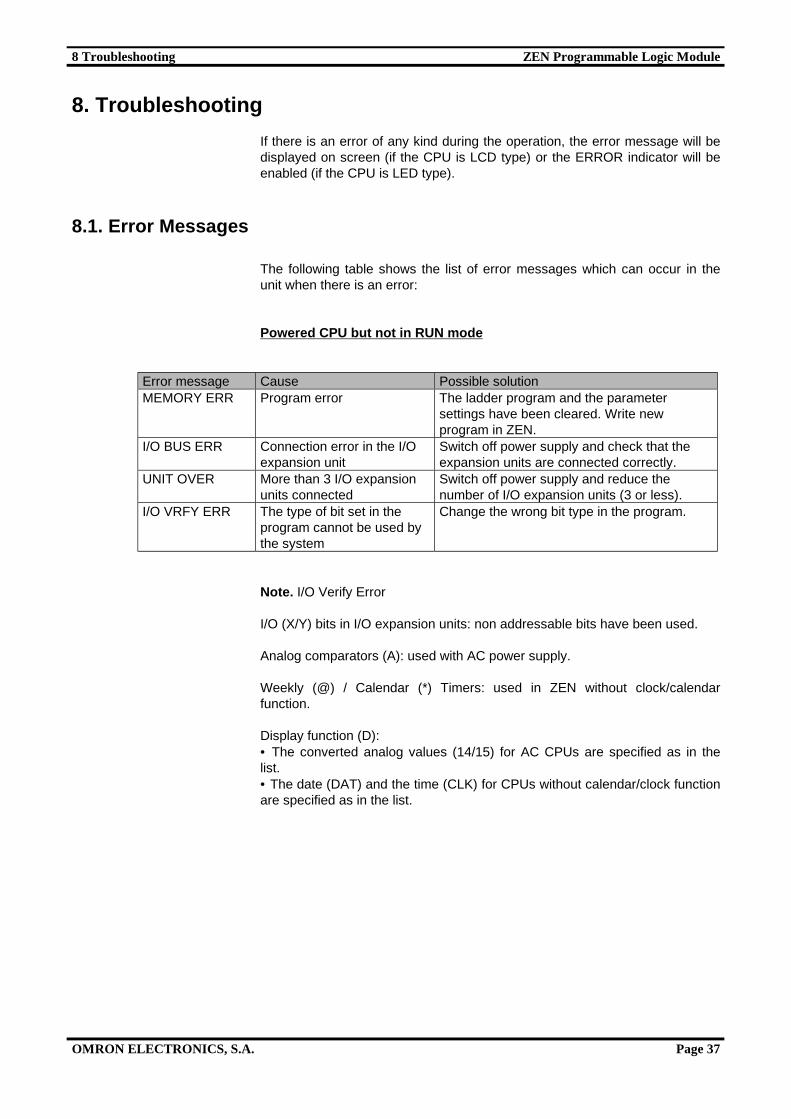
Powered CPU but not in RUN mode
Error message Cause Possible solutionMEMORY ERR Program error The ladder program and the parameter
settings have been cleared. Write newprogram in ZEN.
I/O BUS ERR Connection error in the I/Oexpansion unit
Switch off power supply and check that theexpansion units are connected correctly.
UNIT OVER More than 3 I/O expansionunits connected
Switch off power supply and reduce thenumber of I/O expansion units (3 or less).
I/O VRFY ERR The type of bit set in theprogram cannot be used bythe system
Change the wrong bit type in the program.
Note. I/O Verify Error
I/O (X/Y) bits in I/O expansion units: non addressable bits have been used.
Analog comparators (A): used with AC power supply.
Weekly (@) / Calendar (*) Timers: used in ZEN without clock/calendarfunction.
Display function (D):• The converted analog values (14/15) for AC CPUs are specified as in thelist.• The date (DAT) and the time (CLK) for CPUs without calendar/clock functionare specified as in the list.
8 Troubleshooting ZEN Programmable Logic Module
OMRON ELECTRONICS, S.A. Page 38
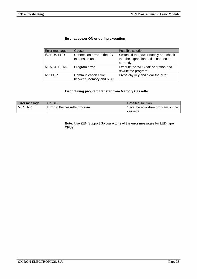
Error at power ON or during execution
Error message Cause Possible solutionI/O BUS ERR Connection error in the I/O
expansion unitSwitch off the power supply and checkthat the expansion unti is connectedcorrectly.
MEMORY ERR Program error Execute the ‘All Clear’ operation andrewrite the program.
I2C ERR Communication errorbetween Memory and RTC
Press any key and clear the error.
Error during program transfer from Memory Cassette
Error message Cause Possible solutionM/C ERR Error in the cassette program Save the error-free program on the
cassette
Note. Use ZEN Support Software to read the error messages for LED-typeCPUs.
9 Accessories ZEN Programmable Logic Module
OMRON ELECTRONICS, S.A. Page 39
9. Accessories
9.1. Battery
The ladder program and all settings are saved on the CPU EEPROM unit, butthe calendar, clock, holding timer bits and the timer/counter present values areheld by the unit capacitor.
In the case of power supply failure, the data can be stored in the CPU forapproximately 2 days (at 25° C) until they are reset.
Installation method:
1. Lean the ZEN-BAT01 battery unit over to one side and insert the clip intothe space provided on the left-hand side of the CPU.
2. Connect the battery cable to the CPU connector.3. And drag the battery clip towards the CPU.
Note. Disconnect the power supply before assembling the battery unit.
9.2. Memory Cassette
Memory Cassettes can also be connected to ZEN to save ladder programsand settings and to copy these ladder programs onto other CPU units.
Installation method:
1. Remove the cover from the CPU front connector2. Connect the ZEN-ME01 memory cassette
Note. Disconnect the power supply before mounting or removing the memorycassette.
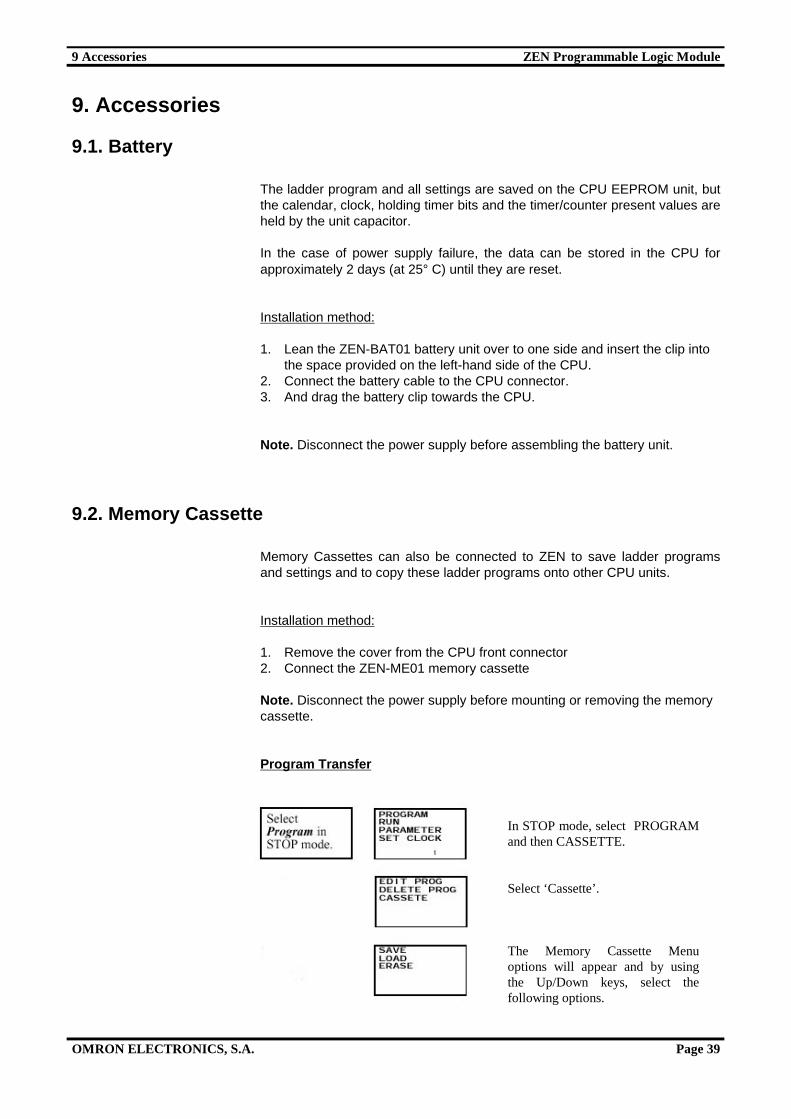
Program Transfer
In STOP mode, select PROGRAMand then CASSETTE.
Select ‘Cassette’.
The Memory Cassette Menuoptions will appear and by usingthe Up/Down keys, select thefollowing options.
9 Accessories ZEN Programmable Logic Module
OMRON ELECTRONICS, S.A. Page 40
Menu OperationSave Transfers the CPU program to the Memory
Cassette. Any program already in the cassettewill be overwritten.
Load Transfers the Memory Cassette program tothe CPU. Any program already in the CPU willbe overwritten.
Erase Clears the program from the MemoryCassette.
Note.1. Program transfer includes the ladder program, parameters and all data
settings. Normal and holding timers, counters and holding bits presentvalues cannot be transferred.
2. Only error-free programs can be transferred. The program will not betransferred if it contains any type of error.
3. The memory cassette allows 100,000 writes.
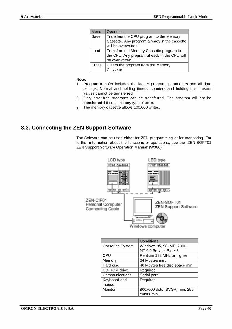
8.3. Connecting the ZEN Support Software
The Software can be used either for ZEN programming or for monitoring. Forfurther information about the functions or operations, see the ‘ZEN-SOFT01ZEN Support Software Operation Manual’ (W386).
ConditionsOperating System Windows 95, 98, ME, 2000,
NT 4.0 Service Pack 3CPU Pentium 133 MHz or higherMemory 64 Mbytes min.Hard disc 40 Mbytes free disc space min.CD-ROM drive RequiredCommunications Serial portKeyboard andmouse
Required
Monitor 800x600 dots (SVGA) min. 256colors min.

9 Accessories ZEN Programmable Logic Module
OMRON ELECTRONICS, S.A. Page 41
Node number setting
When ZEN has to be connected to the Software, the node number displayedboth in the Software and the CPU must be identical. Follow the steps below toset the ZEN node number.
Enter the OTHER option and selectNODE No.
Press the OK key to display the Menu.
By pressing the OK key again, thenode number setting is enabled.
The node number is selected by usingthe Up/Down and Left/Right keys.
Press the OK key to confirm.
Press the OK key again to complete thesetting.