plunger lift algorithms a review - shale tec, llc · pdf filegas well deliquification workshop...
TRANSCRIPT

Gas Well Deliquification Workshop
Sheraton Denver Hotel
Denver, Colorado
February 29 to March 2; 2016
Plunger Lift Algorithms – A Review
David Cosby, P.E.
Shale Tec LLC

2 February 29 to March 2 2016 Gas Well Deliquification Workshop Denver, Colorado
Learning Points
oWhat is an algorithm?
oContinuous vs conventional plunger lift
oWell production goal
oPlunger stage objectives & variation
oPlunger driver
oHow do algorithms relate?

3 February 29 to March 2 2016 Gas Well Deliquification Workshop Denver, Colorado
What is an Algorithm ?
For plunger lift, an algorithm: o Tells the well when to open and close o Records data (Ex: Flow rates, pressures, arrivals) o Initiates receiving and/or transmitting data
noun a process or set of rules to be followed in calculations or other problem-solving operations, especially by a computer

4 February 29 to March 2 2016 Gas Well Deliquification Workshop Denver, Colorado
Open Condition Examples
Timer > or = set point
Tubing pressure > or < set point
Casing pressure > or < set point
Line pressure > or < set point
CP-TP > set point
CP-LP > set point
TP-LP > set point
CP-LP AND TP-LP > set point (1) For user defined time period
Open Condition Examples
Slug size > set point
Load factor < set point
Load factor < set point (1) AND CP > LP (1)
Maintain plunger velocity within user selected range
Throttle control valve to maintain down stream pressure or flow rate
Manual open
Open conditions are in play after allowed plunger fall time elapses
Which to choose ??
What is an Algorithm ?
5 February 29 to March 2 2016 Gas Well Deliquification Workshop Denver, Colorado
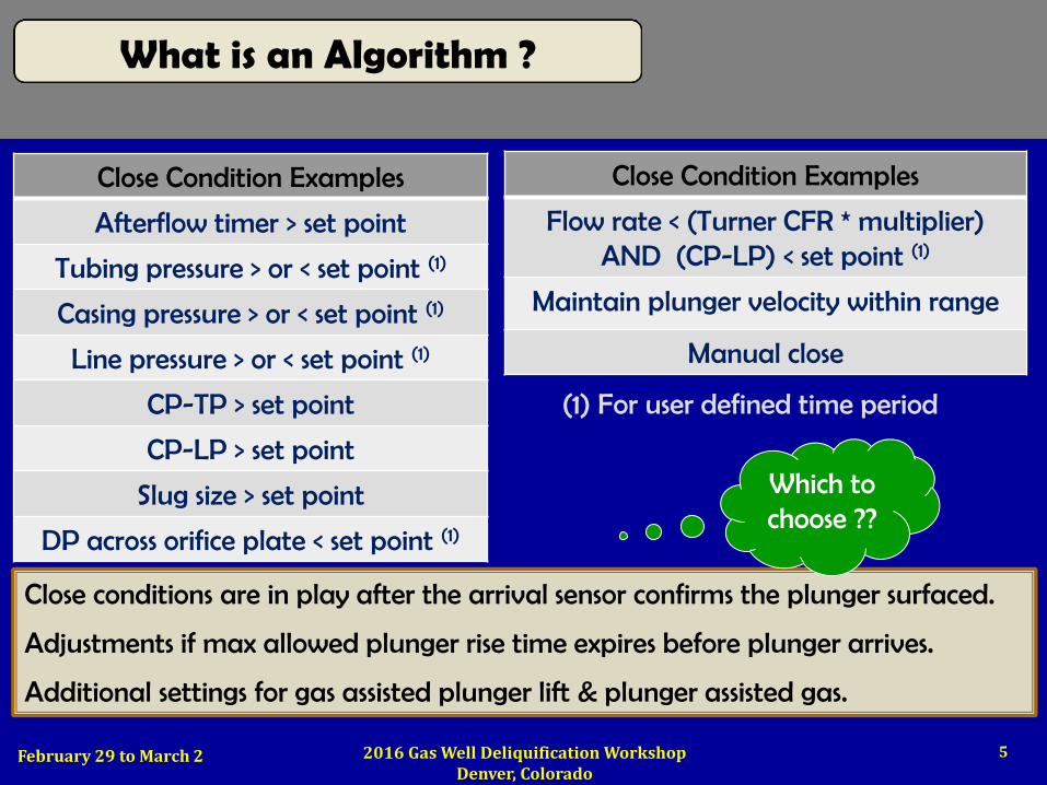
Close Condition Examples
Afterflow timer > set point
Tubing pressure > or < set point (1)
Casing pressure > or < set point (1)
Line pressure > or < set point (1)
CP-TP > set point
CP-LP > set point
Slug size > set point
DP across orifice plate < set point (1)
(1) For user defined time period
Close Condition Examples
Flow rate < (Turner CFR * multiplier) AND (CP-LP) < set point (1)
Maintain plunger velocity within range
Manual close
Close conditions are in play after the arrival sensor confirms the plunger surfaced.
Adjustments if max allowed plunger rise time expires before plunger arrives.
Additional settings for gas assisted plunger lift & plunger assisted gas.
Which to choose ??
What is an Algorithm ?

6 February 29 to March 2 2016 Gas Well Deliquification Workshop Denver, Colorado
CP
LP
TP
Continuous Cycle Plunger Lift
o Plunger falls against flow rate o At bottom, plunger valve closes o Plunger rises. Valve opens at surface. o Afterflow (if desired)
Control Valve
Plunger falls when: o Flow rate is insufficient (bypass adj) OR o Well closed for short period of time OR o Well closed until plunger hits bottom
Monitor expected vs actual RTT. Can use many algorithms to end afterflow. If afterflow, consider an auto-catcher.
Know & monitor SAFE plunger velocity for the equipment utilized.
Consider surface impact velocity sensor.
Separator Rod

7 February 29 to March 2 2016 Gas Well Deliquification Workshop Denver, Colorado
CP
LP
TP
Control Valve
Conventional Cycle Plunger Lift
Stage 1 Plunger fall (gas, liquid)
Stage 2 Casing pressure build
Stage 3 Plunger rise
Stage 4 Production stage
Optimize each stage!

8 February 29 to March 2 2016 Gas Well Deliquification Workshop Denver, Colorado
0
200
400
600
800
1,000
1,200
1,400
1,600
0
200
400
600
800
1,000
1,200
20
-Ja
n
20-F
eb
20
-Ma
r
20
-Ap
r
20
-Ma
y
20
-Ju
n
20
-Ju
l
20
-Au
g
20
-Se
p
20
-Oct
20
-No
v
20
-De
c
20
-Ja
n
20
-Fe
b
20
-Ma
r
20
-Ap
r
20
-Ma
y
20
-Ju
n
20
-Ju
l
20
-Au
g
20
-Se
p
20
-Oct
20
-No
v
20
-De
c
20
-Ja
n
DAILY PRODUCTION
CASING PRESSURE
NATURAL DECLINE CURVE
LOST PRODUCTION
FL
OW
RA
TE
(m
cf)
PR
ES
SU
RE
(p
si)
LIQUID LOADED DECLINE CURVE
LOST PRODUCTION
Well Production Goal

9 February 29 to March 2 2016 Gas Well Deliquification Workshop Denver, Colorado
FLOWING BOTTOM HOLE PRESSURE
Ba
ckp
ress
ure
FB
HP
LOW Backpressure LOW FBHP MOST Production
Produces
Ensures
Line pressure Liquid Scale / Paraffin Chokes Valve trim size Orifice plate 90 degree elbows
Well Production Goal

10 February 29 to March 2 2016 Gas Well Deliquification Workshop Denver, Colorado
Well Production Goal
IPR CURVE
ABSOLUTE
OPEN
FLOW !
100 psi
~ 80 Mcf/d ~ 20 Mcf/d
High Pressure Well
Low Pressure Well

11 February 29 to March 2 2016 Gas Well Deliquification Workshop Denver, Colorado
Plunger Stage vs Variation
Stage Objective Contributors to Variation
Tools
Optimize each stage!
Plunger Fall
Fall time expires when plunger hits the BHS.
Too long is costly!
Height of gas column Height of liquid column Actual fall velocity
Mfr’r data Echometer Wellmaster
CP Build
Lowest CP required to surface plunger
CP typically not the same after a set close time
Foss and Gaul’s CPreq’d
Plunger
Rise
Don’t stall plunger. Don’t damage
equipment. Optimize production!
CP, TP, LP, restrictions,
plunger efficiency.
Liquid load Lift pressure Surface vel.
sensor
Production Mode
Desired volume of liquid in tubing on
every cycle
Liquid load typically not the same after a set open
time interval
Critical flow rate, CP increase

12 February 29 to March 2 2016 Gas Well Deliquification Workshop Denver, Colorado
CP
LP
Control Valve
PLUNGER EFFICIENCY Best – Brush or Pad Worst – Bar Stock
DOWNWARD FORCE Liquid Load (CP-TP)
Line Pressure Restrictions
UPWARD FORCE Casing Pressure
Plunger Lift Driver
TP
LIFT PRESSURE = (CP- LP)

13 February 29 to March 2 2016 Gas Well Deliquification Workshop Denver, Colorado
Considerations o Actual production vs goal? Decline & IPR curve. o Operating at Minimum Open OR Minimum Close? o Packer in well? Can’t use casing pressure algorithms o Line pressure varies? Pipeline pressure or flow limitation? o Casing pressure varies given a set close time? o Liquid in tubing varies given a set open time?
How do Algorithms Relate?
Select an algorithm that accommodates variations and drives to, then maintains the production goal.
Stabilize liquid load and lift pressure on every cycle, then optimize!

14 February 29 to March 2 2016 Gas Well Deliquification Workshop Denver, Colorado
Plunger Fall Pressure Build Plunger Rise End Production
o Time > / = set point o Tubing pressure > / = set point o Casing pressure > / = set point o Tubing / Casing > / = set point o Tubing – Line > / = set point o Casing – Line > / = set point o Casingreq’d > / = Foss and Gaul > / = Multiplier X F&G
o Load Factor < / = Set point
o Time > / = set point o Tubing pressure < / = set point o Casing pressure < / = set point o Casing pressure > / = Increase psi o Flow rate < / = set point < / = Critical flow < / = Multiplier X CFR
Time
Time
How do Algorithms Relate?
Delay Timer

15 February 29 to March 2 2016 Gas Well Deliquification Workshop Denver, Colorado
Layered conditions o Open or close on multiple conditions. o Ex: Close when (CP Rises) or (Flow Rate = Critical) or (Time) expires
Auto cycle algorithms (Initially developed for wells with packers) o Controller self adjusts to maintain a preselected plunger velocity. o User must select “best” plunger velocity for each well. o Algorithm may not directly relate to producing at the lowest FBHP. o When plunger wears, program adjusts to maintain velocity. Production?
Casing pressure rise - can indicate liquid in tubing
Load Factor or Lift Factor o Load Factor = Liquid load / Lift pressure (Industry guideline = / < 0.5) o Lift Factor = Lift pressure / Liquid load (Industry guideline = / > 2.0) o Lift Factor same: LP = 100; LL= 50 AND LP = 50; LL = 25. Lowest FBHP?? o Maintains production, yet may not drive well to lowest FBHP
How do Algorithms Relate?

16 February 29 to March 2 2016 Gas Well Deliquification Workshop Denver, Colorado
Adjustments if missed arrival o Add close time or build to a higher pressure set point before next open. o Some algorithms allow selecting # of sequential misses before shut-in.
If using LP, dump valves must not stick open! Stabilization time or minimum open is important when liquid follows the plunger (Horizontal well or EOT above perf’s)
Plunger arrives
Liquid produced
Stable Gas Flow
Well Opens
CP
Flow Rate
TP
LP
How do Algorithms Relate?

17 February 29 to March 2 2016 Gas Well Deliquification Workshop Denver, Colorado
1. Optimize each plunger stage 2. Select an algorithm for each stage that:
o Best achieves the objective for that stage o Adjusts for known well variations o Drives to the lowest flowing bottom hole pressure o Maintains production on the natural decline curve
“Which to choose”
Stabilize, then
optimize !
Optimize production!
Monitor plunger velocity.
Don’t tear up anything!
Operator knowledge is the
# 1 factor influencing production
Summary

18 February 29 to March 2 2016 Gas Well Deliquification Workshop Denver, Colorado
Continuous Improvement
John Wooden: "When you improve a little each day, eventually big things occur… Not tomorrow, not the next day, but eventually a big gain is made. Don't look for the big, quick improvement. Seek the small improvement one day at a time. That's the only way it happens — and when it happens, it lasts."
UCLA Basketball Coach (1948 to 1975) Won 82.5 % of conference games
10 NCAA Championships in 12 years

19 February 29 to March 2 2016 Gas Well Deliquification Workshop Denver, Colorado
Continuous Improvement
Linkedin Group
“Plunger Lifted Gas Wells”
“Problems are nuggets to be
mined, not garbage to be
buried”
“Getting the Right Things Done”
by Pascal Dennis

20 2016 Gas Well Deliquification Workshop Denver, Colorado
Copyright
Rights to this presentation are owned by the company(ies) and/or author(s) listed on the title page. By submitting this presentation to the Gas Well Deliquification Workshop, they grant to the Workshop, the Artificial Lift Research and Development Council (ALRDC), and the Southwestern Petroleum Short Course (SWPSC), rights to:
– Display the presentation at the Workshop.
– Place it on the www.alrdc.com web site, with access to the site to be as directed by the Workshop Steering Committee.
– Place it on a CD for distribution and/or sale as directed by the Workshop Steering Committee.
Other use of this presentation is prohibited without the expressed written permission of the author(s). The owner company(ies) and/or author(s) may publish this material in other journals or magazines if they refer to the Gas Well Deliquification Workshop where it was first presented.

21 2016 Gas Well Deliquification Workshop Denver, Colorado
Disclaimer
The following disclaimer shall be included as the last page of a Technical Presentation or Continuing Education Course. A similar disclaimer is included on the front page of the Gas Well Deliquification Web Site.
The Artificial Lift Research and Development Council and its officers and trustees, and the Gas Well Deliquification Workshop Steering Committee members, and their supporting organizations and companies (here-in-after referred to as the Sponsoring Organizations), and the author(s) of this Technical Presentation or Continuing Education Training Course and their company(ies), provide this presentation and/or training material at the Gas Well Deliquification Workshop "as is" without any warranty of any kind, express or implied, as to the accuracy of the information or the products or services referred to by any presenter (in so far as such warranties may be excluded under any relevant law) and these members and their companies will not be liable for unlawful actions and any losses or damage that may result from use of any presentation as a consequence of any inaccuracies in, or any omission from, the information which therein may be contained.
The views, opinions, and conclusions expressed in these presentations and/or training materials are those of the author and not necessarily those of the Sponsoring Organizations. The author is solely responsible for the content of the materials.
The Sponsoring Organizations cannot and do not warrant the accuracy of these documents beyond the source documents, although we do make every attempt to work from authoritative sources. The Sponsoring Organizations provide these presentations and/or training materials as a service. The Sponsoring Organizations make no representations or warranties, express or implied, with respect to the presentations and/or training materials, or any part thereof, including any warrantees of title, non-infringement of copyright or patent rights of others, merchantability, or fitness or suitability for any purpose.