pmi m309 diag - Компания ТЕХНО...
TRANSCRIPT
Operator terminals
PMI m309 diag
Operating manual – No. 21870-EN-02

��������� ���������� ������ ������������� ������� ��
����������������������� ����� ��������������������������������������� �������������������� ��� ��� � �����
!������� ��� ������ ��������� ���� ����������� ����� �"�������������������������
����#$��%�#$��&%#$��'()#$������#$��!*'#$��!!#$��+%!#$�!�����,-!� #$�!�����*.*#$!�����'*�� #$������ ��������������#����������������� �� ����������������/������������������������ ������� ������
!0���� ��!����0�������
1PMI m309 diag operating manual
EN
GL
ISH
Introduction 1-1
Overview of operating manual 1-1Definition of symbols 1-3
Overview 2-1
Concept 2-1Components 2-1
Display 2-1Interfaces 2-1
Range 2-2
Safety 3-1
Intended use 3-1Safety regulations 3-2Unit-specific safety regulations 3-3
Unit description 4-1
Front view 4-1Side view 4-2Interfaces 4-3
USB port 4-3
Installation and wiring 5-1
Safety 5-1Installation site and unit surroundings 5-1
Nominal dimensions 5-2Installing the unit 5-3
Installation 5-4
Contents
Contents
PMI m309 diag operating manual2
Connecting the unit 5-5Supply voltage 5-5Cable layout 5-5
Earth connector 5-6Screening 5-6
Measures to protect against interference voltages 5-7Connection example 5-7
Commissioning 6-1
Activating the setup 6-1Control Panel 6-2Default diagnostic setting 6-2PVIS expanded diagnostics 6-3Connect to PVIS OPC Server 6-3
Select device/project (Restore) 6-4Configure connection (Connection Settings) 6-5PNOZmulti/PSS (Serial) 6-5PNOZmulti/PSS (TCP) 6-6Enter PMI’s IP address 6-7Save diagnostic project (Backup) 6-8Select diagnostic language (Language) 6-9
Backup and Restore 6-10Password Settings 6-11System 6-12
Care and maintenance 7-1
Cleaning the touchscreen 7-1Protective membranes 7-1
Appendix 8-1
Technical details 8-1

1-1PMI m309 diag operating manual
This operating manual is valid for the following unit:
PMI m309 diag
It is valid until new documentation is published. The latest documentation isalways enclosed with the unit.
In this manual the unit is called PMI.
The documentation comprises:
• The hardware description for the PMI m309 diag
• A description of the setup and configuration required for connection tothe PVIS OPC Server
A description of the PVIS expanded diagnostics with PVIS ActiveX Controland the connection to the PVIS OPC Server can be found in the followingoperating manual:PVIS System Description
INFORMATIONThis operating manual is intended for instruction and should be retainedfor future reference.
Overview of operating manual
This operating manual is divided into the following chapters:
1 IntroductionThe introduction is designed to familiarise you with the contents,structure and specific instructions in this operating manual.
2 OverviewThis chapter provides information on the unit’s most importantfeatures and gives a brief overview of the application range.
3 SafetyThis chapter absolutely must be read. It contains important informa-tion on safety and intended use.
Introduction

Introduction
1-2 PMI m309 diag operating manual
4 Unit descriptionIntroduces the PMI m309 diag in short, simplified form.
5 Installation and wiringThis chapter describes how to install and wire the PMI m309 diag.
6 CommissioningThis chapter describes the setup and the connection to the OPCServer.
7 Care and maintenanceThis chapter describes how to care for and maintain thePMI m309 diag.
8 Technical details

1-3PMI m309 diag operating manual
Definition of symbols
Information in this manual that is of particular importance can be identifiedas follows:
DANGER!
This warning must be heeded! It warns of a hazardous situation thatposes an immediate threat of serious injury and death and indicatespreventive measures that can be taken.
WARNING!
This warning must be heeded! It warns of a hazardous situation whichcould lead to serious injury or death and indicates preventive measuresthat can be taken.
CAUTION!
This refers to a hazard that can lead to a less serious or minor injury plusmaterial damage, and also provides information on preventive measuresthat can be taken.
NOTICEThis describes a situation in which the unit(s) could be damaged and alsoprovides information on preventive measures that can be taken.
INFORMATIONThis gives advice on applications and provides information on specialfeatures, as well as highlighting areas within the text that are of particularimportance.

Introduction
1-4 PMI m309 diag operating manual
Notes

2-1PMI m309 diag operating manual
Overview
Concept
The diagnostic terminal PMI m309 diag is used for diagnostics onPVIS-compatible devices. Diagnostics are facilitated through theconnection of these devices to the PVIS OPC Server.The PMI is supplied with a default diagnostic configuration and a defaultPMI configuration, so it can immediately be used for device diagnostics(display of system messages).The touchscreen is integrated within a robust housing. The function keyscan be used to call up various defined functions.When installed properly, the front of the unit meets protection type IP65.
Components
Display
• PMI m309 diag: 3.5" (89 mm), 320 x 240 pixels and 32 768 colours
Interfaces
The operator terminal has:
• Two serial RS 232 interfaces; one of the interfaces is switchable(RS 232/422/485).
• One Ethernet interface
• Two USB Host interfaces
• One USB Slave interface
• One audio interface
Overview
2-2 PMI m309 diag operating manual
Range
• Operator terminal
• 4 PMI retaining clamps4 raised head screws (M4)
• Plug for supply voltage
• Documentation
3-1PMI m309 diag operating manual
Intended use
The diagnostic terminal PMI m309 diag is used for diagnostics onPVIS-compatible devices. PVIS-compatible devices are:
• Programmable safety and control systems- (PSS/SafetyBUS p) 3rd generation with an
FS operating system version >= 53
• PNOZmulti safety relays:- PNOZ m0p from Version 2.0- PNOZ m1p from Version 5.0- PNOZ m2p from Version 2.0
Diagnostics are facilitated through the connection of these devices to aPVIS OPC Server.
CAUTION!The unit is not designed for use in applications with high safety require-ments (e.g. E-STOP)!
The unit is designed to be installed within an electromagnetic industrialenvironment. To ensure electromagnetic compatibility, the correct proce-dures must be carried out when installing the unit. Intended use includescomplying with the technical details stated at the end of this operatingmanual. Any component, technical or electrical modifications carried outwill be deemed as improper use.
Safety

PMI m309 diag operating manual3-2
Safety
Safety regulations
Failure to keep to the following safety regulations will render allwarranty and liability claims invalid.Additionally, all rules and regulations for accident prevention for the par-ticular area of application must be met. In particular, VDE and all localregulations regarding safety measures should also be taken into account.Use of qualified operating personnelIt is the owner’s responsibility to employ only personnel who• are familiar with the basic regulations concerning health and
safety/accident prevention,• have read and understood the safety information given in this operating
manual.
Installation and commissioning must only be carried out by competent,qualified personnel. This is particularly important for electrical connections.
CAUTION!Electrostatic discharge can damage components in the unit. Before work-ing in the area of the interfaces and memory cards, ensure against dis-charge by touching an earthed, conductive surface or by wearing anearthed armband, for example.
Warranty and liabilityAll claims to warranty and liability will be rendered invalid if:• The unit was used contrary to the purpose for which it is intended• Damage can be attributed to not having followed the guidelines in the
documentation• Unauthorised modifications were carried out• The unit was used outside the technical specifications• The unit was opened or unauthorised repairs were carried out• Operating personnel were not suitably trained or adequately instructed

3-3PMI m309 diag operating manual
Unit-specific safety regulations
Before you install and commission the unit, you should refer to any regula-tions to this regard as laid down by the controller manufacturer or owner.
• Installation site- Do not position PMI m309 diag close to flammable materials.- When installing the unit within a control cabinet, you must ensure the
unit’s venting slots are not obstructed, otherwise the unit could bedamaged via overheating.
- Protect the unit from direct sunlight and dust.
• Measures to protect against interference- If necessary, use bulkhead separators to protect the unit from sources of
interference.- Inductive loads within the environment (e.g. contactor, relay and sole-
noid valve coils) are to be wired using suppression elements (e.g. RCelements). This is particularly important if these inductive loads are fedfrom the same supply.
- Route power cable physically separate from the data lines (recom-mended minimum distance: 10 cm/3.94"). This will avoid inductive andcapacitive interference.
- Connect the earth point to the earth conductor PE using the shortestpossible copper conductor (cross section ≥ 2.5 mm2).Interference voltages (supply and signal lines) and electrostaticvoltages (contact) are diverted via the earthing point.
• Supply voltage- The supply voltage must be +24 V DC.
WARNING!Safe electrical isolation must be ensured for the external 24 V supply.Failure to do so could result in electric shock. Power supplies must con-form to DIN VDE 0551/EN 60 742 and EN 50178.

PMI m309 diag operating manual3-4
Safety
• Operation- Plan the system correctly to ensure that a communication error
between the PMIvisu/PMIopen and the host computer does not cause amalfunction.
- Do not operate the touchscreen interface using hard or heavy objects orapply excessive pressure.
- The maximum ambient temperature must not be exceeded when usingthe unit.
- Do not pour liquids over the unit or insert any objects into the unit.- When in storage and during operation, protect the unit from vibration
and shock.- Avoid using chemicals close to the unit.
• MaintenanceDo not use thinners or organic solvents to clean the unit andtouchscreen interface.
NOTICEThe touchscreen interface is not abrasion-resistant; if it is dirty, pleaseclean with care and do not apply heavy pressure.
Further information on care and maintenance of the touchscreen can befound in chapter 7.

4-1PMI m309 diag operating manual
1
Fig. 4-1: Front view
32
Front view
1: F1 ... F4 (function keys)2: Touchscreen (see "Technical details")3: ESC, Enter, Cursor Up, Cursor Down
Unit description
PMI m309 diag operating manual4-2
Unit description
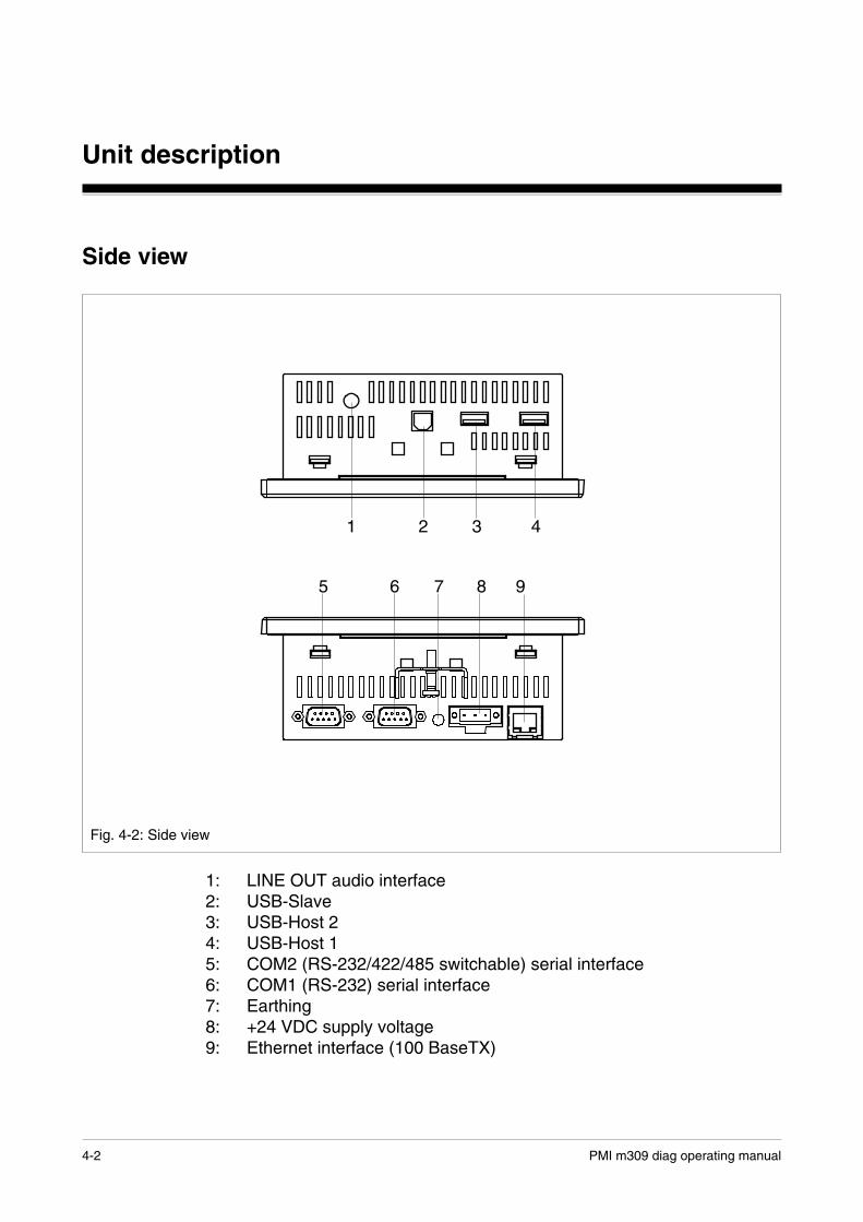
Side view
1: LINE OUT audio interface2: USB-Slave3: USB-Host 24: USB-Host 15: COM2 (RS-232/422/485 switchable) serial interface6: COM1 (RS-232) serial interface7: Earthing8: +24 VDC supply voltage9: Ethernet interface (100 BaseTX)
42
Fig. 4-2: Side view
1 3
7 985 6

4-3PMI m309 diag operating manual
Interfaces
Assignment of the RS-232 interfaces(COM1, COM2 in RS-232 mode)
Assignment of the RS-422/485 interface(COM2, must be switched to RS-422/485 in the setup)
������������
���
��
���
����
��
�
�
�
��
PMI9-pinD-Sub connector
Fig. 4-3: Assignment of the RS-232 interfaces
��� ������� �������
���
���
������
��
�
�
�
��
PMI9-pinD-Sub connector
Fig. 4-4: Assignment of the RS-422/485 interface
USB port
INFORMATIONThe USB port is a standard interface, which is unsuitable for continuousduty in an industrial environment due to its reduced noise immunity. Forthis reason you should limit the time you spend using the USB port to datatransfer and PMI diagnostics.
n.c. = notconnected
n.c. = notconnected

PMI m309 diag operating manual4-4
Unit description
Notes

5-1PMI m309 diag operating manual
Installation and wiring
Safety
Please read the safety guidelines before assembling and installingthe PMI.
Before you install and commission the unit, you should refer to anyregulations to this regard as laid down by the manufacturer or operator.
Installation site and unit surroundings
• Keep as large a distance as possible between the system and any elec-tromagnetic fields, particularly when frequency converters are nearby.
• To avoid the build-up of heat, a distance of 10 cm/3.94" should be main-tained all round the unit.
• Protect the unit from direct sunlight and dust.
• Do not use chemicals close to the unit.
• Ensure the maximum permissible ambient and operating temperaturesare not exceeded.
• Ensure that neither liquids nor objects can enter the unit at any time.
• Do not position the unit close to flammable materials.
Installation and wiring
5-2 PMI m309 diag operating manual
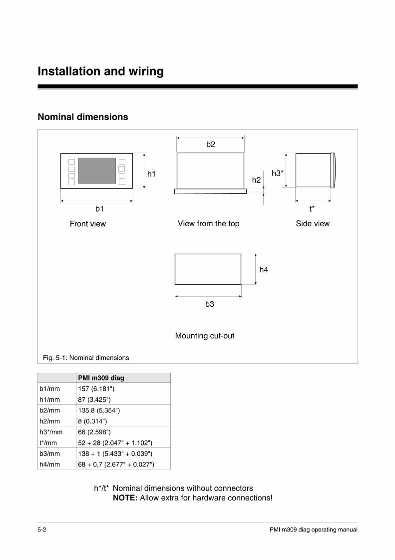
Nominal dimensions
h*/t* Nominal dimensions without connectorsNOTE: Allow extra for hardware connections!
Front view View from the top Side view
Mounting cut-out
h1
b1
b2
h2
t*
b3
h4
b1/mm
h1/mm
b2/mm
h2/mm
h3*/mm
t*/mm
b3/mm
h4/mm
PMI m309 diag
157 (6.181")
87 (3.425")
135,8 (5.354")
8 (0.314")
66 (2.598")
52 + 28 (2.047" + 1.102")
138 + 1 (5.433" + 0.039")
68 + 0,7 (2.677" + 0.027")
Fig. 5-1: Nominal dimensions
h3*

5-3PMI m309 diag operating manual
Installing the unit
When installing the unit, please note the following:
• For reasons of stability, the front panel, console or control cabinet shouldhave a wall thickness of at least 2.5 mm.
• To avoid a build-up of heat, a distance of 10 cm/3.94" should be main-tained all round the unit.
• Ensure the information given for the ambient and operating temperaturesin the Technical details is observed.
• IP65 protection can only be guaranteed when
- the fixing screws are sufficiently tightened.
- the gasket is not damaged.
- the wall thickness is at least 2.5 mm.
• Protect the unit from falling by ensuring that the fixing screws aresufficiently tightened

Installation and wiring
5-4 PMI m309 diag operating manual
Installing
12
21
1 2
1 2
Fig. 5-2: Installing
The PMI 309 fastening kit consists of:
1: Raised head screw (M4)2: Retaining clip
NOTICEThe torque setting for the fixing screws may not exceed 0.25 Nm.

5-5PMI m309 diag operating manual
Connecting the unit
Supply voltage
The 24 V DC supply voltage connection is on the side of the housing(see Fig. 4-2).
Fig. 5-3: Assignment of supply voltage connector
1 2 3
1: Earthing2: 0 V3: + 24 V DC
Cable layout
• Electrical or electronic components which could cause interference (con-tactors, thyristors, relay coils and solenoid valve coils) must be physicallyseparate from data lines.We recommend you use a sheet metal (MU metal) bulkhead betweenboth areas.
• Data lines and power lines must be laid separately to avoidcapacitive and inductive transmission (recommended minimumdistance = 10 cm/3.94").
• Screened data lines also must always be laid in a different cable ductthan the one used for the main power lines.
• Power lines should be as short as possible.
• Power lines should be twisted pair cables.

Installation and wiring
5-6 PMI m309 diag operating manual
Earth connector
• Connect the earthing socket on the housing (press-fit bush M4 on theside of the housing) to the earth bus bar on the control cabinet or unit.Use as short a copper conductor as possible (cross section min. 2.5 mm 2).
• If there are several units in the control cabinet or unit, ensure the earthconductor is connected in a star formation on the bus bar.
• The earth conductor (cross section min. 2.5 mm2) must be connectedto the terminal marked on the supply voltage connector.
Fig. 5-4: Connection diagram for earth conductor
Screening
• Connect the power cable screening with low impedance to earth.
• Use screened data cable only.
• Due to high frequency, we recommend that the screening connection onthe data line cable (RS-232 cable) is earthed on both sides. If you areusing longer cables and there is the possibility of transient currents, werecommend one of the following methods:
- use equipotential bonding cable
- isolate the potentials
• Data line screening is connected to a bus bar.
• The connection between the bus bar and the control cabinet/unit must beshort and with low impedance.
• Fasten the braided screening to the screen bar over as large a surfacearea as possible (e.g. with metal hose clips or polyurethane (PU) cableclips).
5-7PMI m309 diag operating manual
Measures to protect against interference voltage
• Wire inductive loads (e.g. contactor coils, relay coils and solenoid valvecoils) using suppression elements (e.g. RC elements). This is particularlyimportant if these inductive loads are close to the supply voltage or arefed from the same supply voltage.
• If strong magnetic fields are present, we recommend you use a bulkheadseparator, i.e. metal sheet (MU metal).
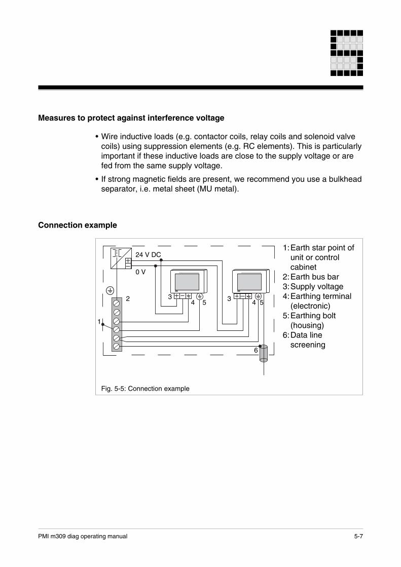
Connection example
1:Earth star point ofunit or controlcabinet
2:Earth bus bar3:Supply voltage4:Earthing terminal
(electronic)5:Earthing bolt
(housing)6:Data line
screening
Fig. 5-5: Connection example
1
24 V DC
2
0 V
34 5 3 4 5
6

Installation and wiring
5-8 PMI m309 diag operating manual
Notes

6-1PMI m309 diag operating manual
Procedure after power-upThere may be a delay of several seconds between power-up and the unitbeing ready for operation.
Activating the setup
If you do not press the SETUP button within 2 seconds, the"PMIStart.cmd" script file will be run. "PMIStart.cmd" is a batch file which isprocessed step by step.
NOTICEThe settings in the PMI configuration must only be changed via SETUP,otherwise the changes will not be applied to the active application.
Commissioning
Fig. 6-1: Setup activation
PMI m309 diag operating manual6-2
Commissioning
Control Panel
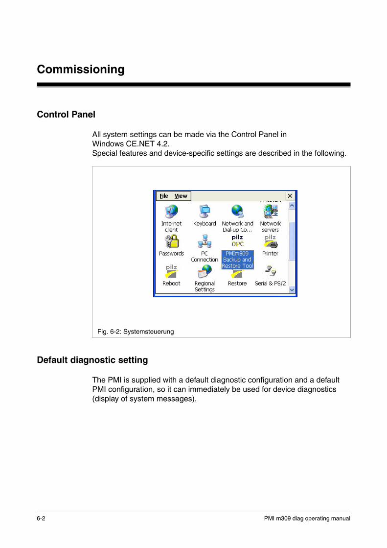
All system settings can be made via the Control Panel inWindows CE.NET 4.2.Special features and device-specific settings are described in the following.
Fig. 6-2: Systemsteuerung
Default diagnostic setting
The PMI is supplied with a default diagnostic configuration and a defaultPMI configuration, so it can immediately be used for device diagnostics(display of system messages).
6-3PMI m309 diag operating manual
PVIS expanded diagnostics
The diagnostic terminal PMI m309 diag is used for diagnostics onPVIS-compatible devices. PVIS-compatible devices are:
• Programmable safety and control systems- (PSS/SafetyBUS p) 3rd generation with an
FS operating system version >= 53
• PNOZmulti safety relays:- PNOZ m0p from Version 2.0- PNOZ m1p from Version 5.0- PNOZ m2p from Version 2.0
Diagnostics are facilitated through the connection of these devices to aPVIS OPC Server.
A description of the PVIS expanded diagnostics with PVIS ActiveX Controland the connection to the PVIS OPC Server can be found in the followingoperating manual:PVIS System Description
Connect to PVIS OPC Server
To configure the necessary settings for PVIS expanded diagnostics on thePMI, activate the applet PMIm309 Backup and Restore Tool.

PMI m309 diag operating manual6-4
Commissioning
Select device/project (Restore)
Under the Restore tab, select the device on which diagnostics are to berun. The following devices are available for selection:
• PNOZmulti
• PSS
INFORMATIONThe default setting is PNOZmulti.
Press Install. A prompt will appear before your selection is saved.
Fig. 6-3: Restore

6-5PMI m309 diag operating manual
Configure connection (Connection Settings)
The connection to PNOZmulti and the PSS can be established either viathe serial interfaces (COM1/COM2 -> PG interface) or via TCP (Ethernet).
PNOZmulti/PSS (Serial)
Select the interface (Port) under the Connection Settings tab.
• COM1
• COM2
Press Set Connection. A prompt will appear before your selection issaved.
Fig. 6-4: Connection Settings PNOZmulti/PSS (Serial)
PMI m309 diag operating manual6-6
Commissioning
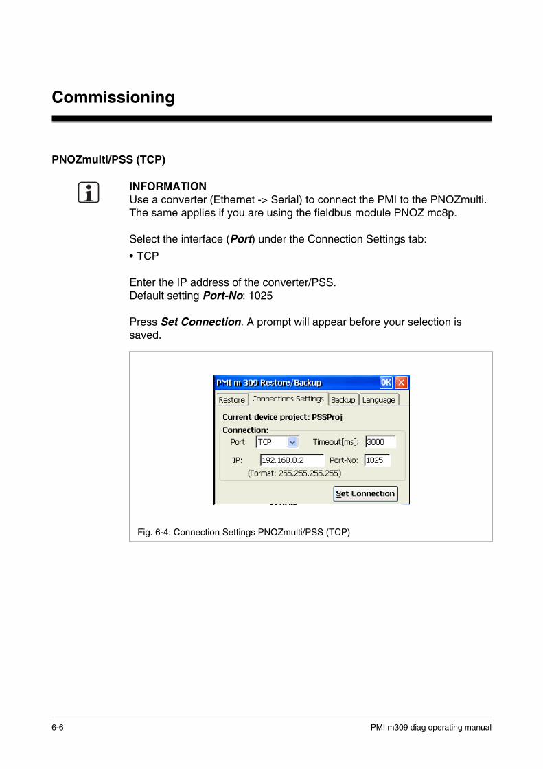
PNOZmulti/PSS (TCP)
INFORMATIONUse a converter (Ethernet -> Serial) to connect the PMI to the PNOZmulti.The same applies if you are using the fieldbus module PNOZ mc8p.
Select the interface (Port) under the Connection Settings tab:
• TCP
Enter the IP address of the converter/PSS.Default setting Port-No: 1025
Press Set Connection. A prompt will appear before your selection issaved.
Fig. 6-4: Connection Settings PNOZmulti/PSS (TCP)

6-7PMI m309 diag operating manual
Enter PMI’s IP address
INFORMATIONIf the PMI is not connected to a network with a DHCP Server, you willneed to enter an IP address for the PMI.
Proceed as follows:
• Under Control Panel, activate the appletNetwork and Dial-up Connections.
A window will open.
• Activate the applet ONBOARD ETHERNET #1.
• Enter the IP address of the PMI.
PMI m309 diag operating manual6-8
Commissioning
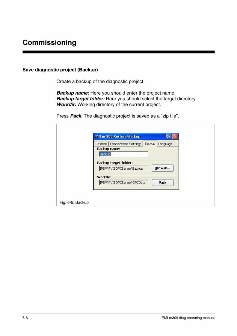
Save diagnostic project (Backup)
Create a backup of the diagnostic project.
Backup name: Here you should enter the project name.Backup target folder: Here you should select the target directory.Workdir: Working directory of the current project.
Press Pack. The diagnostic project is saved as a “zip file”.
Fig. 6-5: Backup
6-9PMI m309 diag operating manual
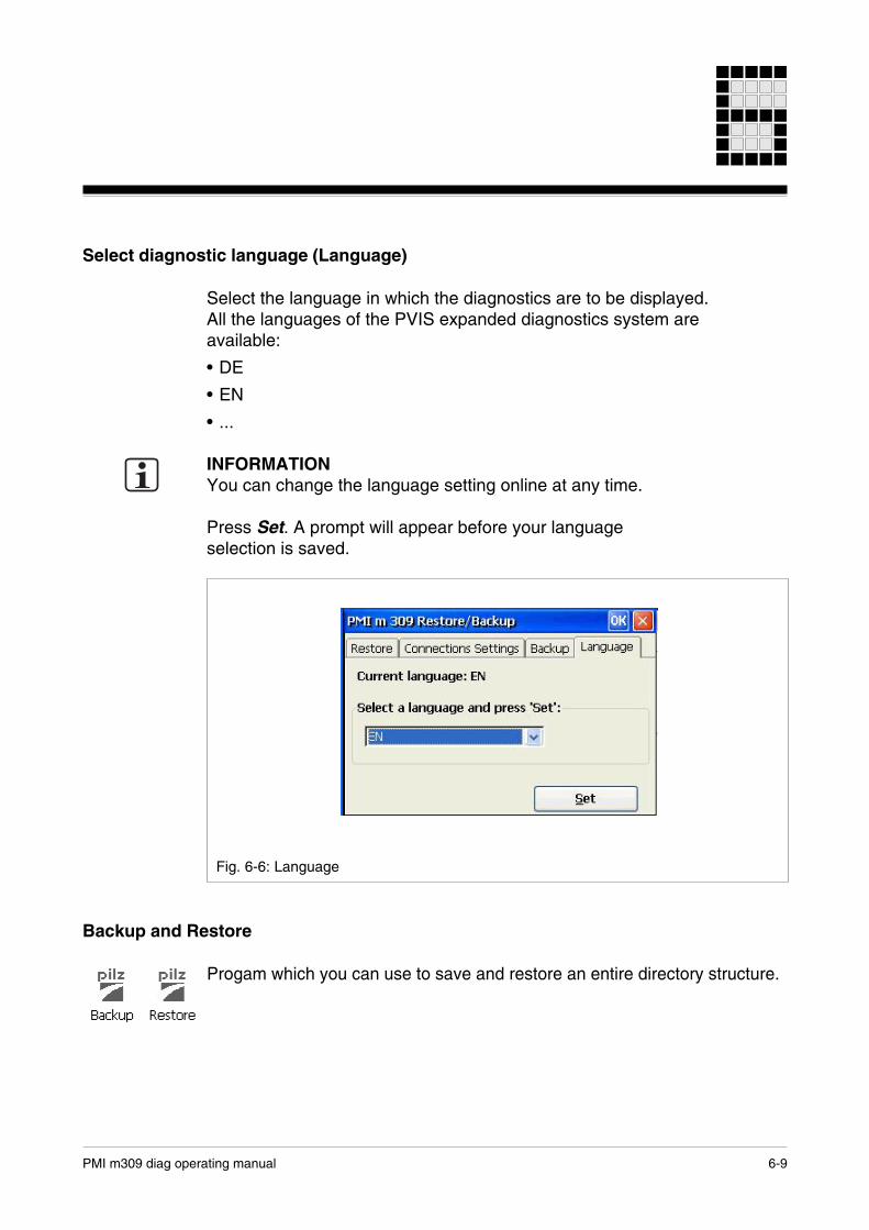
Select diagnostic language (Language)
Select the language in which the diagnostics are to be displayed.All the languages of the PVIS expanded diagnostics system areavailable:
• DE
• EN
• ...
INFORMATIONYou can change the language setting online at any time.
Press Set. A prompt will appear before your languageselection is saved.
Fig. 6-6: Language
Backup and Restore
Progam which you can use to save and restore an entire directory structure.
PMI m309 diag operating manual6-10
Commissioning
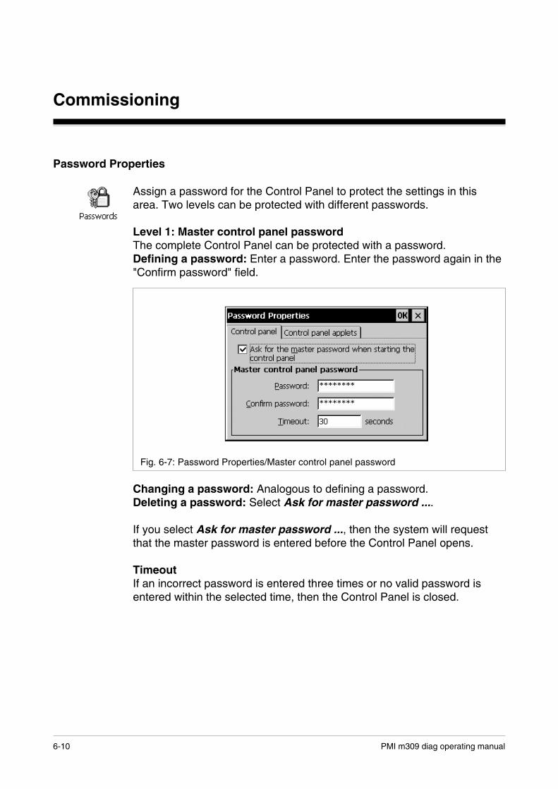
Password Properties
Assign a password for the Control Panel to protect the settings in thisarea. Two levels can be protected with different passwords.
Level 1: Master control panel passwordThe complete Control Panel can be protected with a password.Defining a password: Enter a password. Enter the password again in the"Confirm password" field.
Changing a password: Analogous to defining a password.Deleting a password: Select Ask for master password ....
If you select Ask for master password ..., then the system will requestthat the master password is entered before the Control Panel opens.
TimeoutIf an incorrect password is entered three times or no valid password isentered within the selected time, then the Control Panel is closed.
Fig. 6-7: Password Properties/Master control panel password

6-11PMI m309 diag operating manual
Level 2: Control panel appletsIndividual "applets" of the Control Panel can be protected with a password.
AddAdd "Control Panel applets" to the password protected area. This area isprotected with a password.
RemoveRemove "Control Panel Applets" from the password protected area. Thisarea is not protected with a password.
INFORMATIONAdd Password Properties to the password protected area, as otherwisethe entered password is not protected and is open to being changed.
Fig. 6-8: Password Properties/Control panel applets

PMI m309 diag operating manual6-12
Commissioning
Fig. 6-5: System Compatibility
System
Tab: Compatibility
Flash file system: Enter a name here for the flash memory (e.g.: FlashFS).Second serial port: Select the unit name of the COM interface (COM2 orCOM3) for the second COM interface.
Persistent registry: The registry is a database and is the central storageplace for settings. If this option is selected, then all of the settings made inthe Control Panel are saved in the registry. Otherwise the settings are lostthe next time the system is started.
If this option is deselected, then it is also possible to save the settings byrunning "regsave.exe".
NOTICEIf you delete the registry, the touchscreen calibration will also be deleted;the unit will need to be recalibrated after a restart.
Adjust settings to match PMI 2xx: If you press this button, then all ofthe settings (COM interface etc.) of the predecessor type PMI 2xx aretransferred to PMI.
7-1PMI m309 diag operating manual
Care and maintenance
Cleaning the touchscreen
Clean the touchscreen of the unit at regular intervals. Use a damp cloth todo this.
IMPORTANTMake sure the unit is switched off before cleaning it. This prevents youfrom accidentally triggering functions when you touch the touchscreen.
Cleaning agentsOnly use water and washing-up liquid to make the cloth damp. Neverspray the cleaning agent directly onto the touchscreen - spray it onto thecleaning cloth instead. Never use aggressive solvents or abrasive cleaningagents!
Protective membranes
A protective membrane is available for PMI. However, the protectivemembrane is not supplied with the unit.
Unit
PMI m309 diag
Order number for the protective membrane
On request
The self-adhesive membrane protects the touchscreen against scratchesand dirt.
The protective membrane can be removed at any time as required - with-out leaving any traces of adhesive on the touchscreen.
NOTICENever use a sharp or pointed object (like a knife) to remove the protectivemembrane. This could cause damage to the touchscreen.

Care and maintenance
7-2 PMI m309 diag operating manual
Notes

8-1PMI m309 diag operating manual
Appendix
Electrical data
Supply voltage range
Rated supply voltage
Power consumption
Anzeige
Display type
Screen diagonal
Screen resolution
Touchscreen
Character set
Luminosity halved after(back lighting)
Operating elements
Keyboard type
Number of keys
Average service life
Interfaces
Serial interfaces
USB host interfaces
USB slave interface
Ethernet interface
Computer
Processor
Operating system
Memory
Realtime clock
Environmental data
EMCNoise immunityNoise emission
Protection type (EN 60529 + A1)
20,4 ... 27,6 V DC
24 V DC
typ. 6.0 W
LCD (TFT), 32 768 colours, typ. 200 cd/m²
3.5"/89 mm
320 x 240 pixels QVGA
Analogue-resistive, according to DIN 42115
Unicode
10,000 hrs.
Membrane keypad with snap dome
4 function keys (F1 ... F4),4 system keys (ESC, ENTER, Cursor Up, Cursor Down)
≥ 106 switching cycles
• 1 x RS-232, 9-pin D-Sub connector(s) (male)• 1 x RS-232/422/485 (switchable, driver-dependent);
9-pin Sub-D male connector(s)
2
1
Ethernet RJ45, 10/100 MBit/s
RISC processor, 400 MHz
Windows CE.NET 4.2
• 32 MByte Flash• 64 MByte/128 MByte (optional) SDRAM• 32 KByte NVRAM battery-buffered
Battery-buffered realtime clock
EN 61000-6-2;EN 61000-6-4
Front: IP65, back: IP20
Technical details
PMI m309 diag operating manual8-2
Appendix
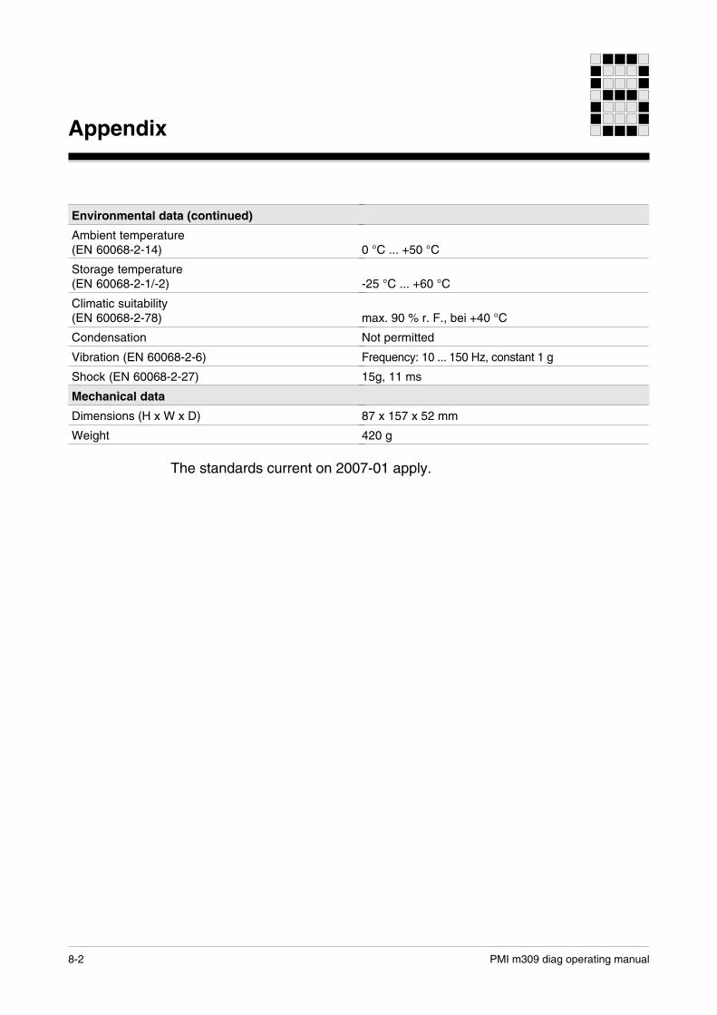
Environmental data (continued)
Ambient temperature(EN 60068-2-14)
Storage temperature(EN 60068-2-1/-2)
Climatic suitability(EN 60068-2-78)
Condensation
Vibration (EN 60068-2-6)
Shock (EN 60068-2-27)
Mechanical data
Dimensions (H x W x D)
Weight
0 °C ... +50 °C
-25 °C ... +60 °C
max. 90 % r. F., bei +40 °C
Not permitted
Frequency: 10 ... 150 Hz, constant 1 g
15g, 11 ms
87 x 157 x 52 mm
420 g
The standards current on 2007-01 apply.

•• …
+49 711 [email protected]
Pilz GmbH & Co. KG Felix-Wankel-Straße 273760 Ostfi ldern, GermanyTelephone: +49 711 3409-0Telefax: +49 711 3409-133E-Mail: [email protected]: www.pilz.com
Technical supportIn many countries we are
represented by our subsidiaries and sales partners.
Please refer to our homepage for further details or contact our headquarters.
Indu
raN
ET
p®, P
ilz®, P
IT®, P
MC
prot
ego®
, PM
I®, P
NO
Z®, P
rimo®
, PS
EN
®, P
SS
®, P
VIS
®, S
afet
yBU
S p
®, S
afet
yEY
E®, S
afet
yNE
T p®
, the
spi
rit o
f saf
ety®
are
re
gist
ered
and
pro
tect
ed tr
adem
arks
of P
ilz G
mbH
& C
o. K
G in
som
e co
untr
ies.
We
wou
ld p
oint
out
that
pro
duct
feat
ures
may
var
y fr
om th
e de
tails
sta
ted
in
this
doc
umen
t, de
pend
ing
on th
e st
atus
at t
he ti
me
of p
ublic
atio
n an
d th
e sc
ope
of th
e eq
uipm
ent.
We
acce
pt n
o re
spon
sibi
lity
for
the
valid
ity, a
ccur
acy
and
entir
ety
of th
e te
xt a
nd g
raph
ics
pres
ente
d in
this
info
rmat
ion.
Ple
ase
cont
act o
ur T
echn
ical
Sup
port
if y
ou h
ave
any
ques
tions
.
2187
0-E
N-0
2, 2
012-
04 P
rinte
d in
Ger
man
y©
Pilz
Gm
bH &
Co.
KG
, 201
1