pneumatic proportional controller types m… types fm… · pneumatic booster valve. connection...
TRANSCRIPT

Operating Manual LTIA5E
Pneumatic proportional controller Types M… Types FM… Function tested for use of the float in Ex-zone 0 Contents 1. Safety Instructions 2. Conformity to standards 3. Technical data 4. Installation and initial start-up 5. Fault finding 6. Maintenance 7. Replacement of the controller module 8. Fire protection 9. Disposal Legend
Information: Application hints and important information. To be followed for optimal function.
Attention: Requirements and prohibitions to prevent damages, especially to material and the
environment.
Danger: Dangerous situation that can lead to injury and death if instructions are not followed.
______________________________________________________________________________________________
www.besta.ch Page 2 of 7 LTIA5E / 2010.01
1. Safety Instructions
The operating manual must be read and understood before installation. If you are uncertain on any point, please contact Besta AG.
During work in potentially explosive atmospheres at the operator’s site, please ensure that you always observe the special regulations applicable to work on Ex-devices (applies to type series FM…).
Every Trimod Besta level controller must be selected by qualified personnel in accordance with the specifications stipulated by the customer. These specifications must be kept by the operator in a safe place, together with the operating manual, the customer-specific designation and the type number (see type plate). In the event of any deviation of the physical quantities (pressure, temperature, density, etc.) from the original specification, the suitability of the level controller must be checked again by qualified personnel or by the manufacturer with regard to the new specifications. Process vessels / float chambers must be brought to atmospheric pressure and appropriately vented before work is carried out.
The Trimod Besta level controllers must under no circumstances be used as a support aid or as a security fixture for equipment structures or persons.
2. Conformity to standards The Trimod Besta level controllers of type series M… correspond to the requirements of the Machine Directive 98/37/EC. In addition, the Trimod Besta level controllers of type series FM… correspond to the requirements of the standards according to EN 50284:1999, EN 50014:1997 +A1 +A2 3. Technical data Pneumatic connection Supply air (compressed air quality) : Quality class 3 to ISO 8571 (max. particle size 5 μm, max. particle density 5 mg/m³) Control pressure : 1.4 bar higher pressures are possible, subject to a reduction of the control ratio (max. 10 bar) Output signal : 0.2 to 1 bar Internal opening at 10 bar : 1.5 mm Flow rate : 3.5 to 6.0 Nl/min
The connection of the type series FM… should be carried out in accordance with the rules and safety regulations for Ex-devices.

www.besta.ch Page 3 of 7 LTIA5E / 2010.01
Operation with higher control pressure (max. 10 bar)
Control pressure Output signal in bar Control ratio bar min. max. Pmax / Pmin 2 0.25 1.50 6.00
4 0.60 3.10 5.17
6 1.10 4.80 4.36
8 1.80 6.50 3.61
10 2.50 8.30 3.32
Principles of use The modules of the type series M… are simple proportional controllers, without provision for adjustment of the rate time or the reset time. In practice, the low flow rate through the aperture in the connection port “p” usually necessitates the use of a pneumatic booster valve. Connection diagram
(Fig. 1) Filling (Fig. 2) Emptying Control function
In the condition as supplied, the connections are at the bottom. This means that, as the level increases, the output signal decreases proportionally (see Fig. 1).
The opposite function (see Fig. 2) can be achieved by rotating the complete controller housing with respect to the flange unit. For this, it is simply necessary to remove the two M6 screws and re-assemble the housing with the connections at the top.
Float at top : 0.2 bar Float at bottom : 1.0 bar
Float at top : 1.0 bar Float at bottom : 0.2 bar
www.besta.ch Page 4 of 7 LTIA5E / 2010.01
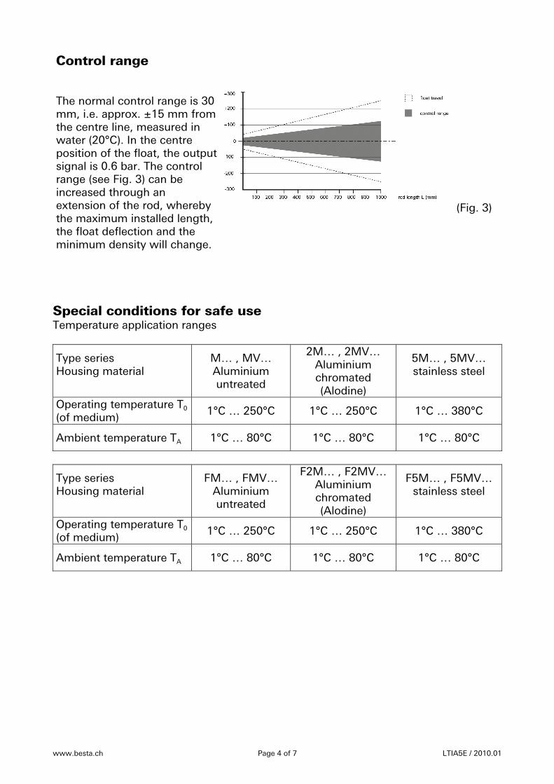
Control range The normal control range is 30 mm, i.e. approx. ±15 mm from the centre line, measured in water (20°C). In the centre position of the float, the output signal is 0.6 bar. The control range (see Fig. 3) can be increased through an extension of the rod, whereby the maximum installed length, the float deflection and the minimum density will change.
(Fig. 3)
Special conditions for safe use Temperature application ranges
Type series Housing material
M… , MV… Aluminium untreated
2M… , 2MV… Aluminium chromated (Alodine)
5M… , 5MV… stainless steel
Operating temperature T0 (of medium) 1°C … 250°C 1°C … 250°C 1°C … 380°C
Ambient temperature TA 1°C … 80°C 1°C … 80°C 1°C … 80°C
Type series Housing material
FM… , FMV… Aluminium untreated
F2M… , F2MV… Aluminium chromated (Alodine)
F5M… , F5MV… stainless steel
Operating temperature T0 (of medium) 1°C … 250°C 1°C … 250°C 1°C … 380°C
Ambient temperature TA 1°C … 80°C 1°C … 80°C 1°C … 80°C
www.besta.ch Page 5 of 7 LTIA5E / 2010.01
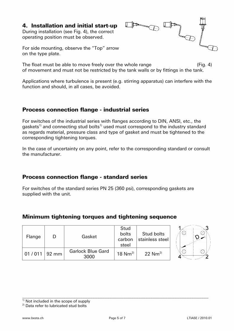
4. Installation and initial start-up During installation (see Fig. 4), the correct operating position must be observed. For side mounting, observe the “Top” arrow on the type plate. The float must be able to move freely over the whole range (Fig. 4) of movement and must not be restricted by the tank walls or by fittings in the tank. Applications where turbulence is present (e.g. stirring apparatus) can interfere with the function and should, in all cases, be avoided. Process connection flange - industrial series For switches of the industrial series with flanges according to DIN, ANSI, etc., the gaskets1) and connecting stud bolts1) used must correspond to the industry standard as regards material, pressure class and type of gasket and must be tightened to the corresponding tightening torques. In the case of uncertainty on any point, refer to the corresponding standard or consult the manufacturer. Process connection flange - standard series For switches of the standard series PN 25 (360 psi), corresponding gaskets are supplied with the unit. Minimum tightening torques and tightening sequence
Flange D Gasket
Stud bolts
carbon steel
Stud bolts stainless steel
01 / 011 92 mm Garlock Blue Gard 3000 18 Nm2) 22 Nm2)
_____________________________________________________________________________ 1) Not included in the scope of supply
2) Data refer to lubricated stud bolts
www.besta.ch Page 6 of 7 LTIA5E / 2010.01
Connecting 1. Remove protective plugs from the valve body 2. Assemble the hose or pipe screwed connection according to the control function and check that it is correctly seated.
If operation appears faulty, clean the aperture in the connection port “p” with needle.
4. Carefully allow the control pressure (supply air) to build up. CAUTION: use only clean control air; if necessary, install a filter!
5. Fault finding
Fault correction / rectification • Is the housing leak-proof - bolts well tightened? • In the case of type series MV…/FMV… - is the vent valve leak-proof? • Remove the jet and clean connection port “p” with needle or compressed air! • Remove any dirt particles which may be present in the threaded bore of the jet! • Use only clean compressed air; if necessary install a filter! • Check the compressed air!
Never adjust nuts / regulating screws for the jet needle in the interior of the housing!
• Connection port “E” must always be open / vented! 6. Maintenance
Level controllers must be periodically (min. 1x annually) inspected and cleaned. Procedure: 1. Detach the flange connection and remove the controller. 2. Check the float and mechanism for damage and contamination. 3. Remove deposits and metal particles by means of suitable and approved methods.
Care must be taken to ensure that no mechanical damage occurs as a result of the cleaning.
4. In the case of floats with protective bellows, the bellows must be removed before cleaning and should be cleaned separately, both internally and externally.
5. Inspect the float and mechanism for complete deflection, as well as for smooth and unrestricted operation.
6. In the event that it becomes necessary to replace individual components, please note that only original spare parts, split pins, float, controller module, etc. may be installed.
7. After completion of the cleaning / inspection work, the controller module must be checked for correct function by means of simultaneous complete deflection of the float, followed by recording in the inspection log book.
8. In order to guarantee the absence of leaks between process vessel / float chamber, the flange gasket must be replaced after each dismantling.
9. After carrying out the inspection work, the device is re-assembled at the intended location.
Adjustment screws in the interior of the housing must not be adjusted!
www.besta.ch Page 7 of 7 LTIA5E / 2010.01
7. Replacement of the controller module Defective controller modules must be replaced with new, works-tested units. In order that the complete type designation can be stamped on the type plate, the complete designation of the existing controller must be specified at the time of ordering. If a complete identification of the controller is not possible, then the manufacturer should be consulted before dispatching the complete device.
In the case of uncertainty on any point, please contact the local Trimod Besta agent or the manufacturer.
Replacing the controller module
Important notes: The level controller does not have to be removed from the process vessel in order to replace the controller module.
Procedure: 1. Observe Chapter 1 “Safety instructions”. 2. Detach the hose or pipe screwed connection from the valve body. 3. Remove socket head cap screws from housing with Allen key (5 mm). 4. Carefully remove the controller module from the flange. 5. Fit a new gasket on the flange and check that it is correctly seated. 6. Place the replacement controller module (incl. gasket) on the flange and tighten
the socket head cap screws with the Allen key. 7. Assemble the hose or pipe screwed connection in the valve body and check that it
is seated correctly. 8. Carefully allow the supply air (pressure) to build up. 8. Fire protection Trimod Besta level controllers must be protected against external fire hazard. 9. Disposal Trimod Besta level controllers are free of any asbestos-containing or otherwise hazardous materials. Disposal must be carried out in an environmentally-friendly manner and in accordance with the local regulations. ______________________________________________________________________________ Besta AG, Ackerstrasse 45, CH-8610 Uster / Switzerland Phone +41 43 399 15 15, Fax +41 43 399 15 00 Email [email protected], www.besta.ch ______________________________________________________________________________ With reservation of technical modification