pneumatic suction and force conveyor s 1000s 1000 · pneumatic suction and force conveyor s 1000 is...
TRANSCRIPT

Silovej 1, Assentoft DK-8960 Randers SØ, Denmark Phone +45 86494566, www.assentoftsilo.dk
PNEUMATIC SUCTION AND FORCE
CONVEYOR S 1000S 1000S 1000S 1000
INSTRUCTION MANUAL (ORIGINAL)
SPARE PARTS CATALOGUE
Edition III
Denmark, 2007
Eng


2
PNEUMATIC SUCTION AND FORCE
CONVEYOR S 1000
(DIAMETER OF PIPELINE 160 mm)
PKWiU: 29.22.17-10.20
INSTRUCTION MANUAL
SPARE PARTS CATALOGUE
Serial number …………….
Year of production …………….
Edition III
Denmark, April 2007 r.
3
CONTENTS
INTRODUCTION 3
1. INSTRUCTIONS FOR A SAFE USE 4
2. WARNING AND INFORMATION GRAPHICS 5
3. USE 7
4. TECHNICAL FEATURES 8
5. CONSTRUCTION AND OPERATION 10
6. ELECTRICAL INSTALLATION 11
7. PREPARATION FOR USE 13
8. WORK WITH THE CONVEYOR 15
9. WORK IN SUCTION AND FORCE SYSTEM 17
10. WORK IN FORCE SYSTEM 19
11. SERVICE AND REPAIR 20
12. MALFUNCTIONING 21
13. PRESERVATION 22
14. DISMANTLING AND DEMOLITION INSTRUCTIONS 22
15. STANDARD OUTFIT FOR SALE, TRANSPORT 22
16. RESIDUAL RISK DESCRIPTION 24
SPARE PARTS CATALOGUE 25
WARRANTY CONDITIONS 35

4
INTRODUCTION
Instruction manual belongs to the standard outfit of the machine. In case the machine is sold again,
this instruction manual must be given to the end-user.
This instruction manual must be read and followed by all personnel using, setting up or servicing the machine. Following the guidelines included into the present manual will guarantee non-
failure work and effective use of the machine.
Identification details can be found on data plate attached to the conveyor’s framework.
In case of any doubts or incomprehension of text herein, contact the producer of the machine, i.e.:
ATTENTION !
SIGH WARNING OF A DANGER This warning sign points out that important information written herein concerns
danger occurrence. If you see this sign, read through given information and tell
other users about it.
Pneumatic suction and force conveyor can be operated only by an adult person, who has read through
the present instruction manual and has been trained within the scope of occupational health and safety
code required for the operation of such machines.
Regulations concerning accident prevention and Occupational Health and Safety Code must be
absolutely observed.
The producer is not liable for damage caused by improper exploitation of the conveyor or introducing
unauthorized constructional changes in it.
Used in the present instruction manual definitions: right side, left side – determine right and left hand
of observer facing in the direction of rolling the machine forward.
The producer reserves the right to modify the conveyor without the obligation of making amendments
to prior produced machines.
ATTENTION ! Persons under the influence of alcohol, drugs, in bad physical health or bad
mental condition, unauthorized as well as bystanders and especially children
must not use the machine.

5
ATTENTION !
1. When operating the machine in a humid room or area always use water-
tight cables, plugs and sockets which enable applying neutralization or
earthing.
2. In case of long non-exploitation, check connections of neutral conductor
in plugs and sockets before reusing the machine.
1. INSTRUCTIONS FOR A SAFE USE
1. Carefully read through the complete instruction manual before using the machine for the first
time.
2. Before starting the conveyor, check condition of the machine with regard to the instructions
for a safe use.
3. The conveyor must be used only by an adult person who is fully familiar with the present
instruction manual.
4. Using the machine with a mechanical defect is forbidden.
5. Special safety precautions must be taken with dangerous places when starting the machine and
during its work. Find and read adequate information and warn other operators.
6. Before each use, ensure there are no objects inside the conveyor.
7. Before each use, check technical condition of the machine, fastening of every mechanism,
especially the elements of the power transmission system, electrical connectors, a plug, socket
and switch-keys.
8. Before the first use an authorized electrician should check effectiveness of earthing system and
protection of the mains.
9. Never connect conductors to the mains omitting plug-in socket and plug connection.
10. Protect the electrical installation of the conveyor from damp.
11. After connecting the conveyor to the power source, the first starting must be performed
according to chapter “Starting test”.
12. Before setting the machine in motion, ensure there is no person in the proximity and a power
cord is connected to the mains in conformity with the appropriate requirements.
13. The presence of bystanders, especially children at the working machine is forbidden.
14. During a starting the machine, the lever of automatic throttling valve must be in the position
“Z” – start-up.
15. Before starting any maintenance or repair work, always stop the engine and disconnect plug
and socket.
16. Check regularly nuts and screws and tighten up if required.
17. Any repair of electrical installation of the conveyor can be carried out only by an authorized
person. After every such repair, effectiveness of earthing system should be measured.
18. Always, use proper tools and protection gloves for exchanging spare parts.
19. Do not leave working machine without supervision/operator.
20. In case of fire of the electric installation, apply only dry powder extinguisher. Do not use
water neither other extinguishers.
21. With regard to exceeding the allowable sound level, always wear hearing protection, such as
ear defenders. Total permissible time of staying without ear defenders at the working conveyor
is 1 hour.
22. Use only original spare parts.
6
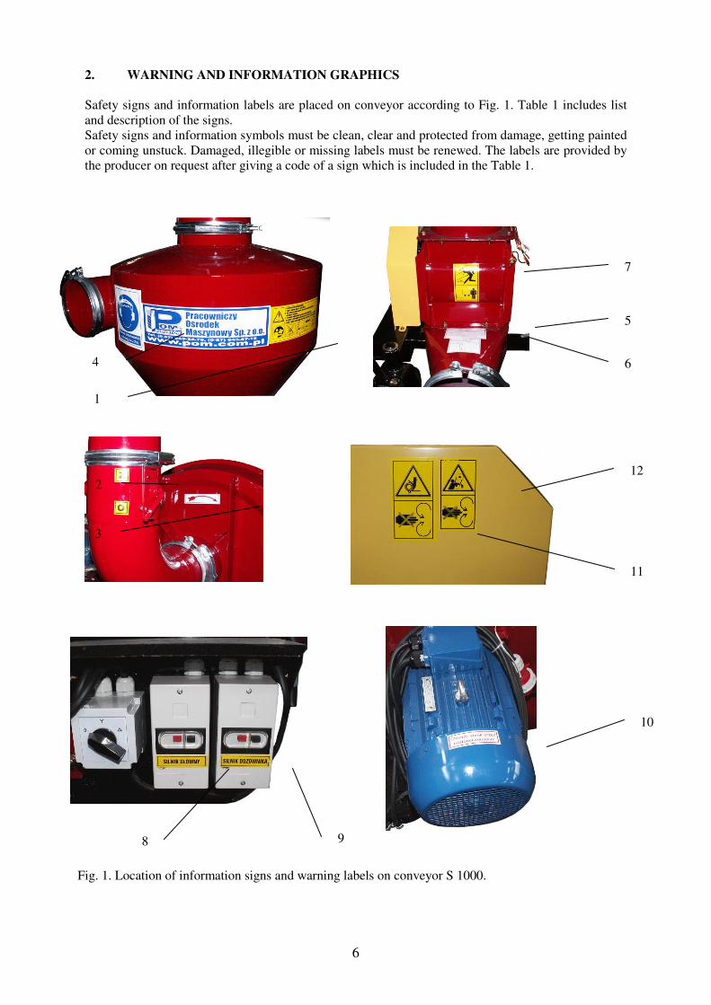
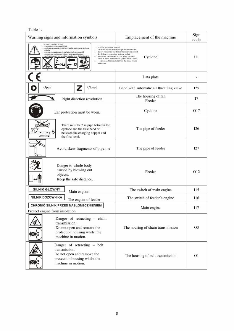
2. WARNING AND INFORMATION GRAPHICS
Safety signs and information labels are placed on conveyor according to Fig. 1. Table 1 includes list
and description of the signs.
Safety signs and information symbols must be clean, clear and protected from damage, getting painted
or coming unstuck. Damaged, illegible or missing labels must be renewed. The labels are provided by
the producer on request after giving a code of a sign which is included in the Table 1.
Fig. 1. Location of information signs and warning labels on conveyor S 1000.
4
1
7
5
6
2 12
11
3
8
10
9

7
8
Table 1.
Warning signs and information symbols Emplacement of the machine Sign
code
Cyclone U1
Data plate -
Bend with automatic air throttling valve I25
The housing of fan
Feeder I7
Cyclone O17
The pipe of feeder I26
The pipe of feeder I27
Feeder O12
Main engine The switch of main engine I15
The engine of feeder The switch of feeder’s engine I16
Protect engine from insolation
Main engine I17
The housing of chain transmission O3
The housing of belt transmission O1
Danger of retracting – belt
transmission.
Do not open and remove the
protection housing whilst the
machine in motion.
Danger of retracting – chain
transmission.
Do not open and remove the
protection housing whilst the
machine in motion.
Danger to whole body
caused by blowing out
objects.
Keep the safe distance.
Avoid skew fragments of pipeline
There must be 2 m pipe between the
cyclone and the first bend or
between the charging hopper and
the first bend.
Ear protection must be worn.
Right direction revolution.
1. read the instruction manual,
2. chilldren are not allowed to operate the machine,
3. do not connect the machine to the mains in case of
the failure of connection unit and socket,
4. use proper connections /socket, plug, electrical cord/ of tested effectiveness against electric shock,
5. disconnect the machine from the mains before
any repair.
Open Closed

9
3. USE
The pneumatic suction and force conveyor S 1000 is used for transporting popular grain, maize, seeds
of leguminous plants or oil seeds. It is suitable for loading grain from means of transport into granaries
and inversely; it can be used for filling up silos and bins as well as aerating grain when stored in piles
with grates and in silos, after prior attaching injector. – in this system, conveyor works with stopped
feeder.
Conveyor can work in two versions: suction and force or force.
In suction and force version, a conveyor sucks grain in through suction nozzle; in force version, grain
is supplied to charging hopper, which is assembled instead of suction cyclone. Further transportation
pipeline in both versions, up to place of storing, can be constructed in any way according to
instructions included in chapter 7 hereof.
Advantages of conveyor are:
- possibility of sucking in grain with suction nozzle,
- possibility to build horizontal as well as vertical pipeline which enables to direct grain to any place,
- possibility of creating the total transport mechanization,
- elimination of the material loss.
Pneumatic suction and force conveyor S 1000 is especially oriented towards family farms, warehouses
where loading and storing grain required. It is not suitable for application in constant work.
ATTENTION !
User looses warranty on the machine in case of:
- damage caused by improper exploitation of the conveyor,
- using it inappropriately,
- introducing constructional changes without prior consent of the producer,
- using spare parts different from the original Trimo POM ones.
CAUTION ! IT IS FORBIDDEN TO:
1. work without the protection housing of the belt and chain transmission or
with damaged housing;
2. look in the end pipeline outlet whilst machine in motion;
3. operate the conveyor by an unauthorized person, bystander, a person
under influence of alcohol or drugs and specially by a minor.

10
4. TECHNICAL FEATURES
Symbol of conveyor S 1000
Performance t/h due to the data mentioned below
Max transportation length m 40
Max transportation height m 10
Diameter of transportation pipe mm 160
Fan – t ype radial
Rotational speed rev/min 2920
Air flow rate m3/h 2600
Total pressure Pa 6000
Electric engine – type Sg 160 S-2B
Power kW 7,5
Rotational speed rev/min 2920
Supply voltage V 3x400
Rated current A 13,7
Feeder – type vane rotational
Diameter mm 230
Number of chambers pc. 6
Rotational speed rev/min 60
Feeder electric engine – type Sg 80-4A
Power kW 0,55
Rotational speed rev/min 1390
Supply voltage V 3x400
Rated current A 1,45
Dimensions:
Length mm -
Width mm 1100
Height mm 1700
Weight kg 240
Noise level dB 94
Operation person 1
Operating parameters of S 1000 in suction and force version
Fig. 2. Pattern of work in suction and force version.

11
Height of transportation H = 3m
Length of
transportation
L(m)
10 20 30 40
Performance (t/h) 5 3,5 2,5 2,3
ATTENTION ! – figures given in the tables are approximate and concern wheat of 700 kg/m3 specific
gravity, humidity up to 14% and dirt to 1%. The values are comparable for grain of barley and maize.
Increase in humidity or dirt of grain may cause decrease of performance up to 20%.
The performance of the conveyor depends on length and height of transport pipeline as well as a kind
and features of transported grain (moisture, dirt level). The total transport length equals to the length
of all vertical and horizontal pipes of both lifting and blowing pipelines.
Ls – length of suction pipeline,
Lt – length of force pipeline,
L= Ls+ Lt
REMEMBER ! The performance is closely connected with the length op pipeline. It falls by ca 4% per each vertical
meter over the height of 3 m; each additional bend equals 5 m horizontal pipeline in performance
decrease. Moisture or dirt growth of grain may cause performance decrease up to 20%.
Operating parameters of S 1000 in force version
Fig. 3. Pattern of work in force version.
Height of transportation H = 3m
Length of
transportation (m) 10 20 30 40
Performance (t/h) 8 5,5 4 3,6

12
5. CONSTRUCTION AND OPERATION
Pneumatic conveyor S 1000 in suction and force version consists of the following units - Fig. 4.
6
1
tabliczkaznamionowa
7 2 3
5
4
Fig. 4. S 1000 in suction and force version.
The drive of the fan of S 1000 contains electrical engine 7,5 kW. Rotational speed of the fan equals
2920 rev/min. At the side of air inlet, the fan is attached to the suction cyclone by means of bend
connector, whereas outlet of the fan is connected by feeder pipe to the vane feeder and transportation
pipeline.
The suction cyclone is located on the vane feeder; to the inlet of the cyclone there is attached the
flexible hose with suction nozzle that sucks grain in. All separate units of the conveyor are joined
together by clamps.
Work in suction and force system
Grain with air is sucked in through suction nozzle and guided by flexible hose to the cyclone.
In the cyclone, grain is separated from air. Grain falls down into the vane feeder which dose it further
to force pipeline. Separated air flows through the pipe connector to the fan which force it to the feeder
pipe and further to forcing pipeline. Strong airflow blows away and snatches grain falling from the
feeder and through tubes transports it to a discharge cyclone assembled at the end of pipeline in the
place of storing – see Fig. 2.
1 – fan
2 – framework/undercarriage
3 – feeder
4 – suction cyclone
5 – compl. suction hose
6 – bend connector
7 – electrical installation

13
Pneumatic conveyor S 1000 in force version consists of the following units and parts – see Fig. 5.:
tabliczkaznamionowa
1 45
326
Fig. 5. S 1000 in force version.
Work in force system:
The conveyor in force version works without flexible hose and nozzle, without suction cyclone and
bend connector. At the side air inlet of the fan, there is a horizontal throttling valve assembled instead
of the bend connector.
Grain should be provided into charging hopper fixed on feeder instead of suction cyclone. The
charging hopper is equipped with protection grid, which prevents objects from entering the feeder, and
also with a bolt regulating the quantity of grain delivered into the feeder. Air, sucked in by the fan, is
forced into the pipe of the feeder and further to blowing pipeline. Strong airflow blows away and
snatches grain falling from the feeder and through tubes transports it to a discharge cyclone assembled
at the end of pipeline in the place of storing – see Fig. 3.
6. ELECTRICAL INSTALLATION
In order to protect operating personnel from electric shock, the conveyor is equipped with
protective grounding which is compatible with protection system in the mains. The electric
installation of conveyor is rated IP-54 of the protection level.
Figure no. 6 presents the diagram of electrical installation of S 1000.
1 – fan
2 – framework/undercarriage
3 – feeder
4 – charging hopper
5 – horizontal throttling valve
6 – electrical installation

14
The electrical installation of the machine includes:
Element of the electrical
installation Characteristic quantity
S 1000
Electric engine
(drive of fan)
power – [kW]
rotational speed – [rev/min]
7,5
2920
Electric engine (drive of
feeder)
power – [kW]
rotational speed – [rev/min]
0,55
1390
Star-delta switch [A] 25
Engine switch with
undervoltage trip
(main)
range of adjustment – [A] 10-16
Trip (of feeder) range of adjustment – [A] 1-1,6
Supply plug [A]/[V] 16/400
Connecting cord symbol, quantity and conductor
section
OPdżo
4x1,5mm2
Spare parts catalogue presents detailed features about elements of the electrical installation (type,
symbol, and trademark).
Electric engines are protected by means of trips equipped with thermal and short-circuit releases.
Adjustments of thermal releases are adjusted to the rated current of engines. With regard to the great
starting current, the engine of fan starts up by means of star-delta switch.
6
7,5kW
M 3
W1 V1 U1
V2 U2 W2
L3 V L2 L12
16
15 14 11
13 12 9 8 5 4 1
10 7 6 3 2
O
U <
L1 L2 L3 PE
I > I > I >
2 4 6I > I > I >
1 3 5
0,55kW
M 3
3
2
5 4
1
1W 2U 1V 2W 1U
1 3 5
2 4 6
Fig. 6. The diagram of electrical installation of conveyors S 1000.

15
1 – electric engine of fan’s drive,
2 – engine switch with undervoltage trip (main),
3 – star-delta switch,
4 – electric engine of feeder’s drive,
5 – trip of the engine of feeder,
6 – supply plug.
The undervoltage trip is an element that prevents self-starting of the machine, which stopped earlier
because of temporary power cut.
7. PREPARATION FOR USE
The surface, on which the conveyor works, should be horizontal and hardened (e.g. paving) to
guarantee the stability of the machine. The power for conveyor is supplied by a power lead 4x1,5mm2
from the nearest supplying point in the work area. The wall electrical system for S1000 should be
made of wire minimum 4x1,5mm2 Cu conforming to building requirements, as well as powered by
voltage 3x400V and protected by time delay cut-out (fuses type C) of ampacity 20A.
A supply socket 16A is necessary to connect the machine to the mains. Before connecting the machine
to the mains, an authorized electrician should check effectiveness of earthing system of the mains.
Before starting the conveyor:
- carefully read through the instruction manual,
- assemble the conveyor according to Fig. 4 or Fig. 5,
- level and reinforce the machine by support leg located on the left side of machine, at feeder,
- install transport pipeline,
- check the condition of clamping rings - tighten up loose ones with regulating screw,
- join the feeder with braid earthing flexible suction hose (the braid is to carry away of electrostatic
charge from the hose during the work of machine); in case of applying a polyurethane hose, join the
end of hose’s steel spiral with copper strand.
ATTENTION !
It is forbidden to operate the machine without prior connected braid earthing
suction hose with the conveyor – risk of static electricity occurrence and electric
shock.
16
1
4
2
53
koñcówka do podlaczenia
z dozownikiem
~5
00
z dozownikiem
koñcówka do podlaczenia
3 1
2
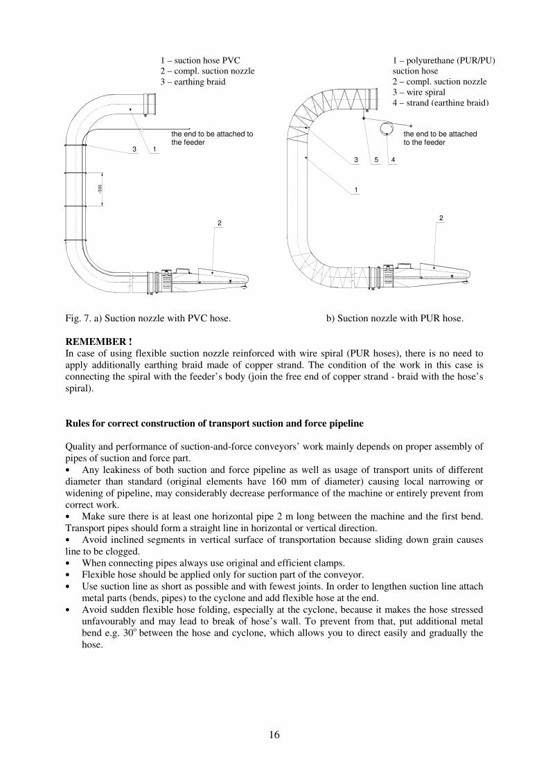
Fig. 7. a) Suction nozzle with PVC hose. b) Suction nozzle with PUR hose.
REMEMBER !
In case of using flexible suction nozzle reinforced with wire spiral (PUR hoses), there is no need to
apply additionally earthing braid made of copper strand. The condition of the work in this case is
connecting the spiral with the feeder’s body (join the free end of copper strand - braid with the hose’s
spiral).
Rules for correct construction of transport suction and force pipeline
Quality and performance of suction-and-force conveyors’ work mainly depends on proper assembly of
pipes of suction and force part.
• Any leakiness of both suction and force pipeline as well as usage of transport units of different
diameter than standard (original elements have 160 mm of diameter) causing local narrowing or
widening of pipeline, may considerably decrease performance of the machine or entirely prevent from
correct work.
• Make sure there is at least one horizontal pipe 2 m long between the machine and the first bend.
Transport pipes should form a straight line in horizontal or vertical direction.
• Avoid inclined segments in vertical surface of transportation because sliding down grain causes
line to be clogged.
• When connecting pipes always use original and efficient clamps.
• Flexible hose should be applied only for suction part of the conveyor.
• Use suction line as short as possible and with fewest joints. In order to lengthen suction line attach
metal parts (bends, pipes) to the cyclone and add flexible hose at the end.
• Avoid sudden flexible hose folding, especially at the cyclone, because it makes the hose stressed
unfavourably and may lead to break of hose’s wall. To prevent from that, put additional metal
bend e.g. 30o
between the hose and cyclone, which allows you to direct easily and gradually the
hose.
1 – suction hose PVC
2 – compl. suction nozzle
3 – earthing braid
1 – polyurethane (PUR/PU)
suction hose
2 – compl. suction nozzle
3 – wire spiral
4 – strand (earthing braid)
the end to be attached to the feeder
the end to be attached to the feeder
17
8. WORK WITH THE CONVEYOR
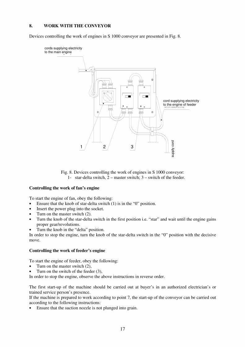
Devices controlling the work of engines in S 1000 conveyor are presented in Fig. 8.
1 2 3
przewód zasilaj¹ cy
silnik dozownika
prz
ew
ód z
asila
j¹cy
silnik g³ówny
przewody zasilaj¹ ce
Fig. 8. Devices controlling the work of engines in S 1000 conveyor:
1- star-delta switch, 2 – master switch; 3 – switch of the feeder.
Controlling the work of fan’s engine
To start the engine of fan, obey the following:
• Ensure that the knob of star-delta switch (1) is in the “0” position.
• Insert the power plug into the socket.
• Turn on the master switch (2).
• Turn the knob of the star-delta switch in the first position i.e. “star” and wait until the engine gains
proper gear/revolutions.
• Turn the knob in the “delta” position.
In order to stop the engine, turn the knob of the star-delta switch in the “0” position with the decisive
move.
Controlling the work of feeder’s engine
To start the engine of feeder, obey the following:
• Turn on the master switch (2),
• Turn on the switch of the feeder (3),
In order to stop the engine, observe the above instructions in reverse order.
The first start-up of the machine should be carried out at buyer’s in an authorized electrician’s or
trained service person’s presence.
If the machine is prepared to work according to point 7, the start-up of the conveyor can be carried out
according to the following instructions:
• Ensure that the suction nozzle is not plunged into grain.
cords supplying electricity to the main engine
cord supplying electricity to the engine of feeder
supply
cord

18
• Ensure that the lever of automatic throttling valve is in the “Z” position (closed valve – start-up) –
see Fig. 9.
• Ensure that the knob of the star-delta switch is in the „0” position.
• Turn on the master switch.
• Start the fan’s engine with the star-delta switch according to the present instruction manual.
• Start the feeder’s engine with the switch of the feeder according to the present instruction manual.
• Release the lever of automatic throttling valve to the “0” position (open valve – work).
ATTENTION ! IMPORTANT !
At the first use, the machine should be idle for ca 5 minutes, i.e. work without transporting grain. In
the meantime, ensure that the machine works evenly, steadily without vibrations and that there are no
alarming sounds such as rasp, grate, rattle, scrubbing.
In case of excessive vibration or alarming sounds of revolving elements, which scrub against some
still parts, stop the machine immediately and pull the power plug out of supply socket. Within bounds
of possibility as well as qualifications and rights (warranty conditions) check and remove the reason of
a failure or contact a technical service.
ATTENTION ! IMPORTANT !
Just before the start-up, check the consistency between the sense of rotation of the fan and the arrow
direction label which is stuck on the housing of the fan; the same, check the consistency between the
sense of rotation of the feeder and the arrow direction label which is stuck on the housing of the
feeder. In order to do so, start the engine of the fan for a while (2-3 seconds) with star-delta switch by
turning it’s knob “0”-“star”-“0”. Control the sense of rotation of the impeller that cools the engine. If
the sense of rotation is the same as the direction of the arrow, the continuation of work is possible -
otherwise, phase sequence in supply installation should be changed. Caution! The conveyor has no
switch reversing the sense of rotation. If a power socket is not equipped with a switch reversing the
sense of rotation an authorized electrician should change phase sequence in a power socket or plug.
ATTENTION ! IMPORTANT !
Star-delta switch can remain in the position “star” only during start-up. Constant work of the engine in
this position may damage it.
Considering great power absorbed by the fan’s engine at start-up, only six starts-up per hour is
permissible, carried out at least every 10 minutes. More frequent starting is harmful to the engine and
may lead to employing the trip (thermal release goes off). Next starting can be carried out just after 15
minutes.

19
po³o¿enie "rozruch"
po³o¿enie "praca"
Fig. 9. Automatic air throttling valve.
The automatic air-throttling valve is designed to regulate airflow blowing through the fan in order to
protect the engine from overloading and that the speed of airflow in pipeline does not exceed 25 m/s.
Revolving blade, which is embedded inside tube, spins round the axle perpendicular to the direction of
airflow and increase or decrease flow capacity of a pipeline. Principle of operation is that the growth
of airflow speed causes overcoming resistance of a spring and gradual closing of the valve. This
prevents the engine from overloading and limits the speed of airflow up to 25 m/s. If the speed of
airflow diminishes for example during sucking grain in, the automatic throttling valve opens to retain
the strength of suction.
REMEMBER !
The greatest load of fan, fan’s engine and drive arises when the machine works without transporting
grain. Reduce pauses in transport to a minimum, and during longer pauses put the lever of the valve in
the “Z” position or stop the machine.
ATTENTION !
Do not leave working machine without supervision/operator.
9. WORK IN SUCTION AND FORCE SYSTEM
After assembly of the conveyor and start-up test, one can begin transportation of grain. While
operating one should observe the following rules:
• After starting the machine – see chapter 8, release the automatic air-throttling valve by holding the
lever of the valve with a hand, pushing blockade and delicate lowering the lever. If the lever is
released too violently, the throttling valve may get into vibration resulting into considerable
vibration of the machine. In this case, the lever should be immediately seized and then delicately
released again. Follow the above when the valve vibrates for different reasons.
• Plunge the suction nozzle into grain and start sucking in.
„start-up” position
„work” position

20
• After finished work pull the suction nozzle out of grain and wait about 1 minute to remove the
remainder of transported grain from pipeline.
• Stop the conveyor.
CAUTION ! The lever of throttling valve, after being released, should be located just under the
blockade. Only after plunging the suction nozzle into grain, the throttling valve opens entirely and the
lever is in the lower position (“O” – work).
CAUTION ! If the lever falls down into the lower position just after releasing the blockade, it means
incorrect work of the valve – further operation in such case will overload and switch off the engine
and may even burn it. When this situation appears, stop the conveyor immediately and contact a
technical service.
Adjustment and regulation of the suction nozzle
The conveyor works properly and optimally if an appropriate proportion between air intake and grain
quantity is maintained. Too much intake of air means the decline in performance. Insufficient intake of
air means grain stuck in pipeline and stoppage in suction part. The suction nozzle, which is fixed to the
end of flexible hose (Fig. 7), allows to determine an appropriate proportion between air intake and
grain quantity.
2
1
otwarcie
zamkniêcie
otwarcie
zamkniêcie
Fig. 10. Suction nozzle.
The suction nozzle consists of two regulation points.
First – movable shield (1) – see Fig. 10. adjusts width of grain inlet slit; for wheat seed, the width
should be about 15mm. In order to change the width of slit, untight all nuts M8 which fix the shield,
adjust demanded width and finally tight the nuts.
Attention: ensure that the width is the same along the whole length of slit.
Second – rotary suction regulator made of metal sheet (2), by means of which a proper proportion
between air and grain is determined depending on length of pipeline as well as a kind and features of
grain. Turning the suction regulator to the right allows to open the slits, to the left – close. At open
slits, the suction nozzle sucks up more grain and less grain, at close on the contrary – less air and more
grain. Be aware of the fact that the longer and higher pipeline the more air should be sucked in through
the slits.
1- shield
2- suction regulator
open close
open
close

21
In order to deter to determine appropriate work of conveyor, note the following:
Plunge the suction nozzle into grain that sounds characteristically (rustles) when running through the
cyclone and pipeline. After 1 minute, pull the nozzle out of grain completely - the rustle should fade
out after 5 min (for the pipeline ca. 20 m long). If the rustle fades out after longer time, it means that
grain is stuck and there is need to supply more air by turning the suction regulator properly. Repeat the
action, and if the grain is still stuck, make the grain intake slit narrower.
An additional measure instrument of correct work is inspection opening located in the lower part of
main cyclone. When properly adjusted suction nozzle, compact grain flow, which is visible through
the inspection opening, runs uniformly down into the feeder. If grain stream is scattered and
incompact and grain flow is chaotic, it means that the suction nozzle is adjusted improperly.
The best results can be obtained when the suction nozzle is put into grain at 45-90 degrees from the
level. It is important, that too deep immersion of the nozzle does not result in sucking in grain between
the shield and body at the top (on the side of flexible hose) and that the grain does not clog
longitudinal slits of suction regulator.
Procedure in case of blockade in transportation pipeline
If a blockade occurs immediately, pull the suction nozzle out of grain and wait about 1 minute until
the whole grain is blown off the pipeline (when stronger air stream at the end of pipeline is
noticeable). If it does not happen so, stop the machine and by tapping the pipeline (dull sound is likely
to be heard) determine the place of blockade which most often appears near bends. Disassemble the
pipeline and remove clogged grain and then assemble it and start the machine. Wait until the grain is
blown off, enlarge air quantity at the nozzle and continue the work.
REMEMBER ! There is a sieve basket (sieve filter) in the main suction cyclone preventing grain from getting into the
fan. In case of very dirt grain with chaff and straw, the sieve filter may be contaminated which may
result in the decrease of suction strength and performance of machine. To remove this inconvenience,
stop the machine, disassemble collector (the element fixed directly on the cyclone), take out the filter
and clean it with a wire brush or blow it through with compressed air.
10. WORK IN FORCE SYSTEM
The conveyor applied for work in force system should be mounted according to Fig. 3 and the rules
included in point 8. Instead of main cyclone, flexible hose with suction nozzle and pipe connector, the
following parts are supposed to be assembled: to the feeder – a charging hopper with grid and bolt and
to the air inlet of fan – horizontal throttling valve. Grain can be directly delivered to the charging
hopper from a trailer or by means of other transportation devices such as platform augers. Depending
on the length of transportation, the bolt should be adjusted according to the rules like in suction and
force system, i.e. the longer pipeline, the narrower opening of the bolt in hopper (more air).
The basic advantage of the work in force system is much higher performance of the machine and
possibility to transport small fine seed e.g. rape which in suction and force work may get into the fan
and damage it.
ATTENTION ! IMPORTANT !
The horizontal throttling valve in force construction works in the same way as throttling valve in
suction and force construction. When starting the machine, the automatic throttling valve should be in
the “Z” position – start-up. The process of releasing the valve should be carried out like in suction and
force system. Released lever should reach the middle of its operating range in case of short forcing
pipeline. During transport by long force pipeline, the lever should entirely go down.

22
11. SERVICE AND REPAIR
Brief intervals in operating of the conveyor do not make the necessity of carrying out specialist
maintenance. Only daily ordinary service and protection from direct adverse weather conditions are
essential.
Daily service
Before work with conveyor, check the following:
- completeness of the conveyor,
- reliability of screw joints,
- reliability of pipe connections.
After work, remove remainder of transported material from the machine. Eliminate immediately
noticed faults. Clean the sieve filter from dust, chaff and straw. Remove any dirt from electric engines
to provide them sufficient cooling during work.
Periodical service
Service inspection carried out every 100 hours of work covers:
- examination of v-belts and chain,
- regulation of v-belts and chain tightness,
Periodical inspection carried out every 500 hours of work covers:
- examination of the technical condition of engines and electrical system (inspection should be made
by an authorized electrician); remove dust and different dirt from the engines and electric units; check
endings of engine clamps, the effectiveness of earthing system, the sate of the plug, socket and wiring,
- inspection of working parts (belt pulleys, chain wheels, bearings, transporting pipes),
- inspection of feeder tightness – if there is a lack of tightness, shift rubber pads which are attached to
the blades of rotor until they rub against the housing of feeder.
- examination of the coat of paint; in case of any paint loss remove rust from damage surface, degrease
and cover it with the paint of the conveyor’s colour.
- lubrication of chain (use grease for conservation of roll chains or graphite grease).
Adjusting the tightness of v-belt and chain of feeder
In order to regulate the v-belt and chain of feeder, unscrew and remove the cover of feeder’s
transmission. At first, regulate a slack of chain that should equal about 5 mm. In order to do so, loosen
the nut of mandrel on which hub with belt pulley and chain wheel rotates and then adequately move
over to the feeder and tight the nut.
Adjustment of belt’s tightness consists in loosening screws fastening the engine and lifting it up as
much as the belt pressed by a finger with strength ca 50N (5kg), weighs down for ca 10 mm. Then
tight screws that fasten the engine and again fix the cover.
Adjusting rubber pads of feeder
In order to regulate rubber pads in feeder, unfasten clamps and remove main suction cyclone (or
charging hopper) from a feeder. Then observe the following instructions:
- unscrew bolts M6,
- move a rubber pad to the point of contact with the surface of feeder’s sidewall, mark the position of
the pad in relation to the metal plate of rotor (mark a line along the edge of the metal plate),
- turn the rotor and pull out a rubber pad for about 2 mm,
- tight up in moderation fastening screws M6,
- adjust the rest of rubber pads in the same way,

23
- fix the cyclone and clamps.
While exchanging rubber pads take the same action and pay attention to place and way of assembling
pads and fastening elements.
Lubrication
Only the chain of feeder needs periodical lubrication. Regarding low load and low revolutions of
transmission, the chain can be lubricated with proper grease once a year.
ATTENTION ! 1. Before beginning any maintenance and repair work, always stop the conveyor
and disconnect plug and socket.
2. At any maintenance and repair work, use proper tools and gloves.

24
12. MULFUNCTIONING
Defect Cause Troubleshooting
master switch turns off when
starting machine
air throttling valve is not
closed (lever in the position
„o”- work)
too big starting current caused
by voltage drop in the mains
invert lever in the position
„z”- start-up
change the place of power
supply or call an electrician
and examine the condition of
wiring system
low capacity dirt sieve basket
throttling valve in the position
„z” – start-up
too much air in pipeline
wrongly constructed
transportation pipeline
grain clogged in pipes
untight feeder
moist and dirt grain
clean sieve basket
release lever to the position
„o”- work
regulate suction nozzle
check the correctness and
tightness of pipeline
connections
clean pipes, regulate suction
nozzle
adjust or exchange rubber
pads
adjust suction nozzle by
enlarging air supply
grain blockage in feeder feeder switched off start the engine of feeder

25
13. PRESERVATION
After finished season, a conveyor should be thoroughly cleaned from the residue of grain and dust and
a sieve basket should be blown out. Dismantle flexible suction hose, elements of transportation
pipelines and put aside separately in the place where they can be protected from damage. Put a
conveyor into a roofed, dry, airy place, on hard ground. Duly cover transport openings of cyclone and
pipe of feeder in order to prevent rodents from getting inside through them. Protect electric system
from moisture. During maintenance or longer break in exploitation, keep children and animals away
from the conveyor and its elements.
14. DISMANTLING AND DEMOLITION INSTRUCTIONS
While dismantling and demolition of a conveyor obey the following rules:
• Collect dismantled metal parts in one place and classify them – useless parts give to a scrap metal
collection point.
• During demolition, collect metal parts separately in order to scrap them and take rubber or plastic
elements to utilization management centre.
ATTENTION !
Stored parts after dismantling and demolition should be protected and beyond the
reach of children and animals.
15. STANDARD OUTFIT FOR SALE, TRANSPORT
Pneumatic suction and force conveyor S 1000 can be purchased directly from a producer i.e. POM
Augustów Sp. z o. o. or sales outlets of agricultural machines. A buyer is provided with partially
dismantled conveyor i.e. pipe 2 m long, bend and flexible hose with suction nozzle are disassembled
from a machine. A conveyor may be transported by any means of motor or rail transport in accordance
with road and PKP (Polish State Railways) regulations.
When transported, a conveyor should be thoroughly protected against undesirable movement by
means of transport belts and wooden slats minimum 40x40x1000 mm.
a) b)
Fig. 11. Standard outfit for sale S 1000: a) suction and force version; b) force version.
Standard outfit of pneumatic conveyor in suction and force version consists of:
• Conveyor with main cyclone, bend connector, flexible PVC hose and suction nozzle- 1 pc.

26
• Transport metal pipe 2m with clamp - 1 pc.
• Transport bend 90o - 1 pc.
• Support leg for pipeline - 1 pc.
• Instruction manual with spare parts catalogue
• Warranty card
• CE certificate
Standard outfit of pneumatic conveyor in force version consists of:
• Conveyor with charging hopper and horizontal air throttle valve - 1 pc.
• Transport metal pipe 2m with clamp - 1 pc.
• Transport bend 90o - 1 pc.
• Support leg for pipeline - 1 pc.
• Instruction manual with spare parts catalogue
• Warranty card
• CE certificate
On request, the producer can supply the following optional parts:
• Transport metal pipes 2m or 1m
• Transport bends 90, 60, 45, 30 and 15 degrees
• Clamps φ150, 160, 200 mm
• Discharge cyclone (discharge ending)
• Handle of suction nozzle
• Support leg for pipeline
• Adapter φ160/180mm
• Suction PUR hose of higher wear resistance
In order to load a conveyor on means of transport use lifting devices of minimum 300kg hoist
capacity.
The following picture presents the way of loading that the producer recommends.
Fig. 12. Loading on means of transport.
1. Information label – fulcra for forks of fork-lift

27
16. RESIDUAL RISK DESCRIPTION
Although, the producer takes responsibility for the construction and labelling of the pneumatic
conveyor S 1000 in order to eliminate dangers during work, service and maintenance, there is still
portion of risk remaining.
Residual risk results from incorrect or improper conduct of an operating person.
The worst danger occurs at the performing forbidden actions such as:
- misuse or use in contradiction with instructions,
- operation by minors or persons not acquainted with the instruction manual,
- leaving the machine in motion without supervision,
- operation by persons under influence of alcohol or drugs,
- repairs, modifications or service of electric installation by yourself/ unauthorized personnel,
- pulling out a plug off socket before turning the switch off,
- climbing the machine during its work or stop,
- moving the machine in motion or connected to the power supply,
- removing protection housings when the engine works,
- starting the machine when a plug or socket is faulty or damaged,
- any operation or adjustment of the machine when the engine works,
- looking in grain outlet when the machine is in motion.
At introducing the residual risk, pneumatic suction and force conveyor S 1000 should be regarded as
machines that have been designed and made according to the contemporary state of technology to the
moment of starting the production.
Residual risk assessment
If the following principles are observed:
- carefully read through the instruction manual,
- do not climb the machine during its work or stop,
- do not perform any repairs, modifications or service of electric installation yourself/ by an
unauthorized person,
- keep your hands off dangerous or forbidden places,
- all repairs of electric installation must be carried out only by an authorized electrician,
- before using the machine and after performed repairs of electric installation always check
effectiveness of sockets’ neutralization,
- only a person familiarized with the instruction manual can operate the machine,
- keep children away from the machine,
residual risk of the use of the pneumatic suction and force conveyor S 1000 can be eliminated
without threat to people and environment.
WARNING !
The residual risk occurs in case of ignoring all mentioned above hints and rules.

28
SPARE PARTS CATALOGUE
Spare parts for the conveyor S 1000 can be ordered according to the spare parts catalogue from the
producer, i.e.:
Pracowniczy Ośrodek Maszynowy w Augustowie Sp. z o. o.
or from an authorized seller after giving:
- exact address of an ordering person,
- exact address of a receiver,
- name, symbol, serial number of machine and year of construction,
- full name and catalogue number of requested spare part
Contents
Table 1: Suction and force conveyor
Table 2: Framework/undercarriage
Table 3: Feeder cpl.
Table 4: Suction unit
Table 5: Electrical system

29
4
6
7
21
18
178
4
9
11
13
12
10
9
5
20
16
5
3
2
1
11
10
17
18A
14
15A
19
22
23
24
18
25
26
27
28
29
30
31
17
18
SUCTION AND FORCE CONVEYOR S 1000

30
SUCTION AND FORCE CONVEYOR S 1000 TABLE 1
Fig. No. Name Catalogue no.
or norm no.
Quantity
piece(s) Remarks
1 Fan 7207/21-000/1 1
2 Clamp φ160 7378/07-000/0 1
3 Washer Dz54 7378/01-004/1 2
4 Spring washer 12,2 PN-/M-82008 5 galv.
5 Screw M12x40 PN-/M-82105 5 galv.
6 Key 10x7x63 PN-/M-85505 1
7 Engine Sg132 S-2B, 7,5kW,
2920obr/min
Prod. Tamel S.A. 1
8 Nut M12 PN-/M-82144 4 galv.
9 Round washer 13 PN-/M-82030 8 enlarged
10 Screw M10x25 PN-/M-82105 6 galv.
11 Spring washer 10,2 PN-/M-82008 6 galv.
12 Round washer 10,5 PN-/M-82030 8 enlarged
13 Nut M10 PN-/M-82144 4 galv.
14 Data plate - 1
15 Rivet φ3x6 PN-/M-82971 4 aluminium
16 Suction unit 7207/03-000/1 1
17 Nut M6 PN-/M-82144 9 galv.
18 Spring washer 6,1 PN-/M-82008 11 galv.
19 Round washer 6,4 PN-/M-82030 1 enlarged
20 Feeder cpl. 7207/04-000/1 1
21 Screw M8x45 PN-/M-82406 2 galv.
22 Right bracket 7207/31-302/0 1
23 Left bracket 7207/31-303/0 1
24 Screw M6x20 PN-/M-82105 3 galv.
25 Washer 6,4 PN-/M-82005 3 galv.
26 Spring washer 8,2 PN-/M-82008 2 galv.
27 Nut M8 PN-/M-82144 2 galv.
28 Shield 7207/04-070/4 1
29 Framework/undercarriage 7207/22-000/2 1
30 Concave elastic fastener - 4 2xM6; φ32x21
31 Electrical system 7207/01-500/1 1

31
FRAMEWORK/UNDERCARRIAGE
9
7
5
4
3
15
6
8
11 10 16
210 1
13
12
14

32
FRAMEWORK/UNDERCARRIAGE cat. No. 7207/22-000/2 TABLE 2
Fig. No. Name Catalogue no.
or norm no.
Quantity
piece(s) Remarks
1 Framework 7207/22-100/0 1
2 Wheel 7207/01-060/0 3
3 Connection clip 7207/02-020/1 1
4 Pin 7207/02-001/0 1
5 Support leg 7207/51-040/0 1
6 Handwheel of support leg 7207/51-120/1 1
7 Handle 7207/02-030/0 1
8 Blockade 7207/02-003/0 1
9 Bushing 7207/31-053/0 2
10 Ring Z25 PN-/M-85111 3
11 Washer φ25,5 7207/02-002/0 1
12 Nut M10 PN-/M-82144 1
13 Spring washer 10,2 PN-/M-82008 1
14 Washer 10,5 PN-/M-82005 1
15 Screw M10x60 PN-/M-82101 1
16 Cotter pin 3x25 PN-EN 1234 1
33
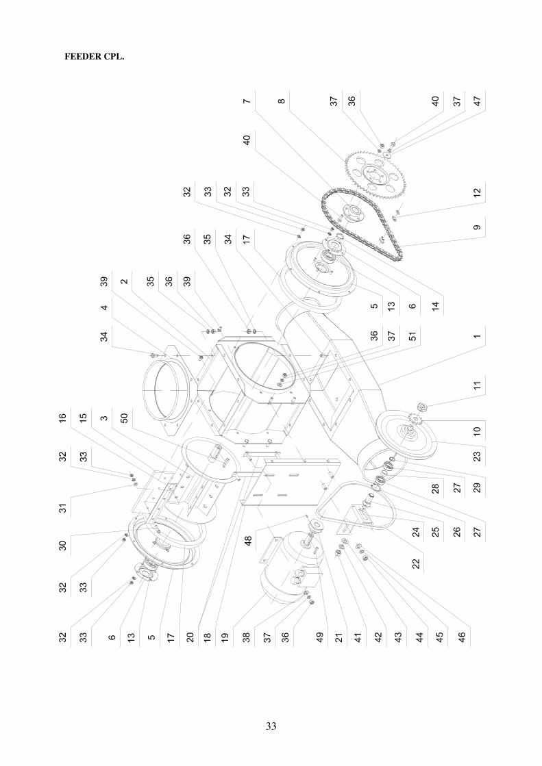
FEEDER CPL.
51
33
32
40
35
10
25
42
37
37
48

34
FEEDER CPL. cat. No. 7207/04-000/1 TABLE 3
Fig. No. Name Catalogue no.
or norm no.
Quantity
piece(s) Remarks
1 Pipe of feeder 7207/08-000/0 1
2 Body of feeder 7207/04-010/1 1
3 Rotor 7207/04-020/1 1
4 Cover of feeder 7207/04-080/0 1
5 Side cover 7207/04-030/1 2
6 Lid 7207/04-003/1 2
7 Hub cpl. 7207/04-061/0 1
8 Chain wheel z-56 motor-bicycle part 1
9 Chain 1/2” x 3/16” motor-bicycle part 1 36 links
10 Chain wheel z-12 motor-bicycle part 1
11 Nut 7207/04-052/0 1
12 Chain pin 1/2” x 3/16” motor-bicycle part 1
13 Bearing 6205-2RS PN-/M-86100 2
14 Spacer washer 7207/04-000/1 1
15 Rubber pad 7207/04-002/1 6
16 Tightening strip 7207/04-001/1 6
17 Gasket 7207/04-004/1 2
18 Engine base 7207/04-041/0 1
19 Engine Sg80-4A, 0,55 kW,
1390 rev/min
- 1 prod. Tamel
20 Screw holder 7207/04-090/0 2
21 Belt pulley Dp-45 7207/04-014/0 1
22 V-belt Z-850 PN-/M-85201 1
23 Belt pulley cpl. 7207/04-050/0 1
24 Bracket cpl. 7207/04-011/0 1
25 Axle of tightener 7207/04-051/0 1
26 Ring W 35 PN-/M-85111 1
27 Bearing 6003-2RS PN-/M-86100 2
28 Distance sleeve 7207/04-053/0 1
29 Ring Z 17 PN-/M-85111 1
30 Screw M6x25 PN-/M-82105 24
31 Washer 6,4 PN-/M-82005 24
32 Washer 6,4 PN-/M-82024 44 toothed
33 Nut M6 PN-/M-82144 44
34 Screw M8x16 PN-/M-82105 16
35 Washer 8,4 PN-/M-82024 16 toothed
36 Nut M8 PN-/M-82144 29
37 Spring washer 8,2 PN-/M-82008 14
38 Nut 8,4 PN-/M-82005 4
39 Screw M6x12 PN-/M-82202 12
40 Screw M8x20 PN-/M-82105 6
41 Nut M12 PN-/M-82144 1
42 Spring washer 12,2 PN-/M-82008 1
43 Round washer 13 PN-/M-82030 2 enlarged
44 Nut M10 PN-/M-82144 2
45 Spring washer 10,2 PN-/M-82008 2
46 Round washer 10,5 PN-/M-82030 2 enlarged
47 Washer A9 PN-/M-82019 1
48 Set screw M6x10 PN-/M-82273 1
49 Key A 6x6x30 PN-/M-85005 1
50 Key A 8x7x40 PN-/M-85005 1
51 Round washer 8,4 PN-/M-82030 4 enlarged

35
SUCTION UNIT
1
6
17
26
27
21
30
25
31
29
36
35
32
33
34
28
27
28
36
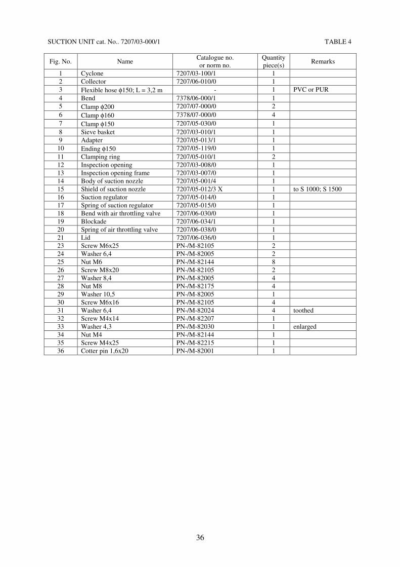
SUCTION UNIT cat. No.. 7207/03-000/1 TABLE 4
Fig. No. Name Catalogue no.
or norm no.
Quantity
piece(s) Remarks
1 Cyclone 7207/03-100/1 1
2 Collector 7207/06-010/0 1
3 Flexible hose φ150; L = 3,2 m - 1 PVC or PUR
4 Bend 7378/06-000/1 1
5 Clamp φ200 7207/07-000/0 2
6 Clamp φ160 7378/07-000/0 4
7 Clamp φ150 7207/05-030/0 1
8 Sieve basket 7207/03-010/1 1
9 Adapter 7207/05-013/1 1
10 Ending φ150 7207/05-119/0 1
11 Clamping ring 7207/05-010/1 2
12 Inspection opening 7207/03-008/0 1
13 Inspection opening frame 7207/03-007/0 1
14 Body of suction nozzle 7207/05-001/4 1
15 Shield of suction nozzle 7207/05-012/3 X 1 to S 1000; S 1500
16 Suction regulator 7207/05-014/0 1
17 Spring of suction regulator 7207/05-015/0 1
18 Bend with air throttling valve 7207/06-030/0 1
19 Blockade 7207/06-034/1 1
20 Spring of air throttling valve 7207/06-038/0 1
21 Lid 7207/06-036/0 1
23 Screw M6x25 PN-/M-82105 2
24 Washer 6,4 PN-/M-82005 2
25 Nut M6 PN-/M-82144 8
26 Screw M8x20 PN-/M-82105 2
27 Washer 8,4 PN-/M-82005 4
28 Nut M8 PN-/M-82175 4
29 Washer 10,5 PN-/M-82005 1
30 Screw M6x16 PN-/M-82105 4
31 Washer 6,4 PN-/M-82024 4 toothed
32 Screw M4x14 PN-/M-82207 1
33 Washer 4,3 PN-/M-82030 1 enlarged
34 Nut M4 PN-/M-82144 1
35 Screw M4x25 PN-/M-82215 1
36 Cotter pin 1,6x20 PN-/M-82001 1

37
INSTALACJA ELEKTRYCZNA
1
14
13
wspornik prawy
4
5
19
5
2
1
6
9
8
10
7
3
11
4
do silnika wentylatora
26 12
16
15
17
18
do silnika dozownika
ELECTRICAL SYSTEM cat. No. 7207/01-500/1 TABLE 5
Fig. No. Name Catalogue no.
or norm no.
Quantity
piece(s) Remarks
1 Nut M6 PN-/M-82144 2
2 Spring washer 6,1 PN-/M-82008 2
3 Staple 7206/52-001/0 2
4 Screw M6x16 PN-/M-82202 2
5 Nut M4 PN-/M-82144 6
6 Spring washer 4,1 PN-/M-82008 6
7 Engine conductor 7378/01-503/0 1
8 Short conductor 7378/01-502/1 1
9 Screw M4x14 PN-/M-82201 2
10 Supply main 7378/01-501/1 1
11 Plug PCE 16A 3P+E, IP-67 - 1
12 Shield of switches 7207/31-013/2 1
13 Feeder engine conductor 7207/30-103/1 1
14 Choke Pg16 IP-65 - 8
15 Screw M4x10 PN-/M-82201 4
16 Switch SFKOK (Mbs25);
range 10-16A
Undervoltage trip SFBORU
nr w kat. GE – 120011
nr w kat. GE – 120036
1
17 Switch SFKOF (Mbs25);
range 1-1,6A
nr w kat. GE - 120006 1
18 Housing SFS05 IP55 nr w kat. GE - 120041 2
19 Star-delta switch 4G 25-12-PK, 25A - 1
right bracket
to the engine of fan
to the engine of feeder

38
Numbered and registered official form
WARRANTY CARD
for: pneumatic suction and force conveyor S 1000
Symbol ……………… serial number .................................... year of production .....................
Date of purchase (month in words) ............................................................................. 20 ......... Seller fills in at the moment of sale
Date of the first start-up and training of the machine’s user within the scope of safe operation
and exploitation.
...................................................... Date, stamp, signature of the seller
...................................................... Date, signature of the user
............................................ KJ/Quality Control sign
The producer gives twelve-month warranty from the date of purchase.
1) In foreign countries, the seller shall deal with warranty on behalf of the producer.
Name of the seller ......................................................................................................................................
Seller fills in
Address of the seller ....................................................................................................................... Seller fills in
.......................................................................................................................................................
.............................................................. Signature, stamp of the seller
Present the warranty card in case of any claim.
ATTENTION!
A buyer should read carefully the warranty card and refuse it when not completed or corrected.
Lack of the first start-up and training of the user in the range of operation safety and
exploitation principles, confirmed with signature of seller and user shall result in losing
guarantee rights.
GENERAL PRINCIPLES OF WARRANTY PROCEDURE

39
1) The warranty shall cover defects caused by the producer’s fault owing to defective material,
surface finishing or assembly.
Within guarantee period, the producer is obliged to:
a) perform free repair on claimed units,
b) provide new, flawless parts without charge to the buyer,
c) cover the cost of repair with labour and reimburse for incurred costs of transport.
2) The warranty will not cover defects due to normal wear and tear of the components or units.
3) Claims should be submitted directly to the customer service department whose address is
included into the warranty card or to the seller of the complained parts. The seller is obliged
then to pass immediately submitted claim on to the customer service department.
4) The buyer should submit a claim immediately within 14 days from the date of the occurrence
of the damage.
5) The buyer service department should settle the claim within 14 days.
6) Guarantee shall be prolonged to cover a period of repair.
7) The producer shall not accept a complaint if any failure of or damage to the machine/parts is
due to neglect, misuse, mistreatment, failure to maintain or store as well as due to technical
modifications or repairs without POM’s prior consent.
8) The buyer has a right to the reconsideration of the claim by the seller with an expert’s
participation.
9) Civil Code shall be applicable in issues not governed by these principles.
10) Warranty shall not exclude the buyer’s rights deriving from nonconformity of the machine
with an agreement.
11) In order to hold guarantee rights, an operating person/ buyer should be trained within
the scope of safe operation and exploitation rules. The seller provides the training during
the first start-up of the machine. In case of handing the machine over to another user, an
entitled person is obliged to provide the training.
12) Guarantee prolongation notes:
- guarantee is prolonged to ..........................................................................
Date, signature, stamp
- guarantee is prolonged to ..........................................................................
Date, signature, stamp
- guarantee is prolonged to ..........................................................................
Date, signature, stamp

CLAIM VOUCHER № 4
_____________________________ Name of product
______________________ Serial number
______________________ Date of purchase
____________________________ Signature and stamp of sales outlet
Claim report № __________________
Submitted on ____________________
Filled in two-sided voucher should be
forwarded with the claim report to the
producer.
CLAIM VOUCHER № 3
_____________________________ Name of product
______________________ Serial number
______________________ Date of purchase
____________________________ Signature and stamp of sales outlet
Claim report № __________________
Submitted on ____________________
Filled in two-sided voucher should be
forwarded with the claim report to the
producer.
CLAIM VOUCHER № 1
_____________________________ Name of product
______________________ Serial number
______________________ Date of purchase
____________________________ Signature and stamp of sales outlet
Claim report № __________________
Submitted on ____________________
Filled in two-sided voucher should be
forwarded with the claim report to the
producer.
CLAIM VOUCHER № 2
_____________________________ Name of product
______________________ Serial number
______________________ Date of purchase
____________________________ Signature and stamp of sales outlet
Claim report № __________________
Submitted on ____________________
Filled in two-sided voucher should be
forwarded with the claim report to the
producer.

Technically efficient machine
received
on ......................... 20 ....... .
..........................................
Signature of the user
Technically efficient machine
received
on ......................... 20 ....... .
..........................................
Signature of the user
Technically efficient machine
received
on ......................... 20 ....... .
..........................................
Signature of the user
Technically efficient machine
received
on ......................... 20 ....... .
..........................................
Signature of the user