pneumatic tyres interacting with deformable terrains · 2019-08-07 · pneumatic tyres interacting...
TRANSCRIPT

This item was submitted to Loughborough's Research Repository by the author. Items in Figshare are protected by copyright, with all rights reserved, unless otherwise indicated.
Pneumatic tyres interacting with deformable terrainsPneumatic tyres interacting with deformable terrains
PLEASE CITE THE PUBLISHED VERSION
http://dx.doi.org/10.1088/1742-6596/744/1/012213
PUBLISHER
© The Authors. Published by IOP Publishing LTD
VERSION
VoR (Version of Record)
PUBLISHER STATEMENT
This work is made available according to the conditions of the Creative Commons Unported 3.0 International(CC BY 3.0) licence. Full details of this licence are available at: https://creativecommons.org/licenses/by/3.0/
LICENCE
CC BY 3.0
REPOSITORY RECORD
Bekakos, Chrysostomos-Alexandros, George Papazafeiropoulos, D.J. O'Boy, and Jan Prins. 2016. “PneumaticTyres Interacting with Deformable Terrains”. figshare. https://hdl.handle.net/2134/22545.
Pneumatic tyres interacting with deformable terrains
C A Bekakos#1, G Papazafeiropoulos#2, D J O’Boy1 and J Prins3 1 Department of Aeronautical and Automotive Engineering, Loughborough University, LE113TU, UK 2 National Technical University of Athens, 9 Iroon Politechniou Str., Zografou Campus, 15770 Athens, Greece 3 Jaguar Land Rover, Gaydon, CV35 0RR, UK
#1 [email protected] , #2 [email protected]
Abstract. In this study, a numerical model of a deformable tyre interacting with a deformable road has been developed with the use of the finite element code ABAQUS (v. 6.13). Two tyre models with different widths, not necessarily identical to any real industry tyres, have been created purely for research use. The behaviour of these tyres under various vertical loads and different inflation pressures is studied, initially in contact with a rigid surface and then with a deformable terrain. After ensuring that the tyre model gives realistic results in terms of the interaction with a rigid surface, the rolling process of the tyre on a deformable road was studied. The effects of friction coefficient, inflation pressure, rebar orientation and vertical load on the overall performance are reported. Regarding the modelling procedure, a sequence of models were analysed, using the coupling implicit – explicit method. The numerical results reveal that not only there is significant dependence of the final tyre response on the various initial driving parameters, but also special conditions emerge, where the desired response of the tyre results from specific optimum combination of these parameters.
1. Introduction Tyres provide a link between the vehicle and the ground, serving for four main purposes: (a) to support the weight of the vehicle, (b) to develop friction forces in order to accelerate and decelerate the vehicle, (c) develop lateral forces to steer the vehicle and (d) decrease the vibrations of the vehicle due to the irregularities present on the road surface. The tyre’s dynamic response during travelling on off-road surfaces is crucial for the driving behaviour of off-road vehicles. Possible applications where off-road tyre-soil interaction is present include army vehicles, planetary exploration vehicles, as well as agricultural, construction and mining vehicles.
Although the interaction between tyres and urban pavements has received much attention in the past, the same type of interaction in off-road conditions is a subject which has not been thoroughly studied yet. The latter is a relatively complicated phenomenon, since such problems are highly nonlinear due to the material, geometry and contact nonlinearities present, and involve sophisticated models (tyre and/or soil configurations). A variety of many other factors affect the final tyre response; e.g. the carried vertical load, the inflation pressure, the travelling velocity, possible positive or negative slip conditions.
A common assumption for pneumatic tyres inflated with relatively high pressure is their consideration as practically rigid, especially in cases where the tyre is lying on soft soil [1,2]. This assumption does not hold in cases where significant interaction exists between the tyre and the soil; this means that the deformation of one depends on the response of the other and vice versa. Therefore, a more detailed model should be developed for such cases, which will necessarily consider the tyre
MOVIC2016 & RASD2016 IOP PublishingJournal of Physics: Conference Series 744 (2016) 012213 doi:10.1088/1742-6596/744/1/012213
Content from this work may be used under the terms of the Creative Commons Attribution 3.0 licence. Any further distributionof this work must maintain attribution to the author(s) and the title of the work, journal citation and DOI.
Published under licence by IOP Publishing Ltd 1
deformability. In this study, a deformable wheel model is developed in detail, the tyre of which does not represent any real industry tyre, but has been created by the authors purely for research purposes. Initially it was ensured that the tyre model is realistic, by verifying its modal response to external loading. Afterwards, the deformation of the tyre was studied when pressed against a rigid surface by imposing a vertical load at its centre, and the results confirmed that the configuration of the tyre is representative of an industrial tyre. Following this, the response of the tyre was obtained when rolling on a deformable soil surface for various vertical loads and inflation pressures.
2. Literature review The subject of tyre-soil interaction involves many aspects which have been studied by various researchers in the past. The methods of calculation of the response of the tyre-soil system range from simple analytical and/or empirical methods to complicated numerical analyses. The selection of the method to be used depends on the desired accuracy of the results in combination with the affordable computational effort. The methods belonging to the first two categories, although less computationally expensive than numerical methods, lack on the detailed modelling of the tyre along with its inner components, such as belt, carcass and rebar which is offered by numerical methods and could be crucial for the reliability of the results.
2.1. Empirical methods The two main relationships used in the literature relate the pressure developed at the footprint area of the tyre to its sinkage and the shear stress developed at the same area to the shear displacement along the contact interface. One of the first empirical relations proposed for the correlation of the sinkage to the normal pressure on deformable terrain was presented in [3], and later in [4] as a generalized form of the former. The relations proposed are:
0.5k zσ = ⋅ (1) and:
nk zσ = ⋅ (2) respectively. Later in 1956, Bekker introduced two different moduli for the soil, one for the cohesive behaviour and one for the frictional behaviour, as follows:
( ) ( )ncn
k k zb ϕσ θ θ = +
(3)
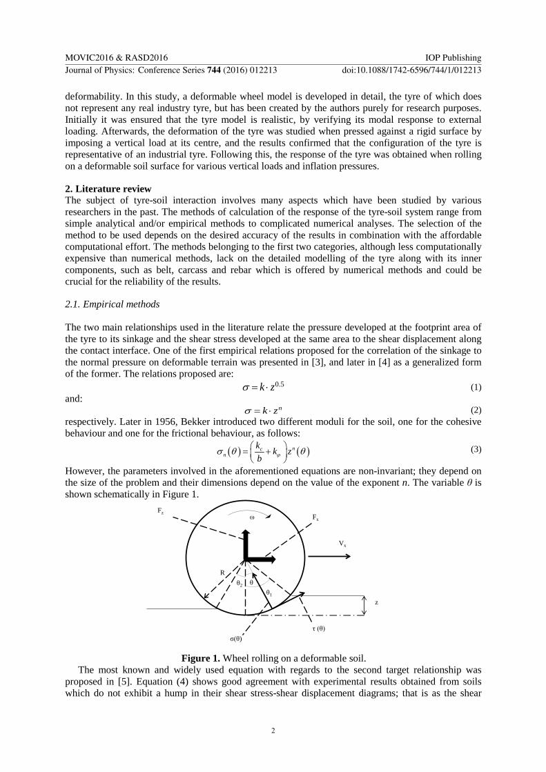
However, the parameters involved in the aforementioned equations are non-invariant; they depend on the size of the problem and their dimensions depend on the value of the exponent n. The variable θ is shown schematically in Figure 1.
Figure 1. Wheel rolling on a deformable soil.
The most known and widely used equation with regards to the second target relationship was proposed in [5]. Equation (4) shows good agreement with experimental results obtained from soils which do not exhibit a hump in their shear stress-shear displacement diagrams; that is as the shear
z
Fz
θ1
θ2
Fx
σ(θ)
θ
τ (θ)
Vx
ω
R
MOVIC2016 & RASD2016 IOP PublishingJournal of Physics: Conference Series 744 (2016) 012213 doi:10.1088/1742-6596/744/1/012213
2

displacement increases, the shear stress reaches a maximum value and remains constant thereafter. Soils exhibiting this behaviour are the loose sand, saturated clay, dry fresh snow and most of the disturbed soils.
( ) ( )( ) ( )/tan 1 e− = + − d dj K
nc θt θ σ θ ϕ (4)
For soils which are exhibiting a hump, two distinct categories were identified in [6] and respective relations have been proposed.
The above basic relations constitute the basis for the development of various other empirical relations published in the literature. By appropriate integrations of the stress distributions along the perimeter of the wheel, the resultant forces (motion resistance, traction force, resisting moment, terrain vertical reaction force, drawbar pull, etc.) are computed.
In [7] a new elastic tyre-soil interaction model is developed for vehicle simulations on deformable ground, such as soft soils or snow. The flexible tyre was considered as a rigid wheel with increased diameter, which is given by the relation:
*
0 01 f fRR z z
= + + (5)
2.2. Analytical methods To overcome the limitations of the empirical methods presented above, analytical methods were developed. These methods have a more sound theoretical background, since they are based on invariant parameters existing at theoretical solutions. In [8] one of the first analytical relationships between vertical displacement and normal pressure for plates on deformable soils assumed to behave as an infinite half-space:
i
z i
B σz arctanhk B
=
(6)
In [9,10] the indentation and rolling process of rigid wheels on cohesive and frictional soils was studied and the so called inclined force and the inclined footing methods were developed. Later on, in [11], a load-sinkage analytical model was developed which utilized four invariant parameters , (c, φ, γ, E) which can be given or measured for any terrain by using classical soil mechanics or routine test methods through hand held instruments. The equation proposed for the normal pressure is:
1 2
i
1D D ω Β ξB E z
=+ ⋅ ⋅ ⋅
⋅
σ (7)
where D1, D2, ω, ξ are dimensionless parameters. A fundamental assumption inherent in all of the aforementioned methods is the existence of a
radial stress distribution along the circumference of the tyre, used for analyzing the latter stress into vertical and horizontal components.
2.3. Numerical methods
Given that the tyres used in practice are very complicated structures which require detailed modelling in order to be analysed, numerical methods are frequently used to estimate their response. Numerical methods allow for detailed modelling of the tyre-soil interaction problem, and are many times the only alternative if the details of the structures involved have to be taken into account. Various numerical methods have been developed including finite element, finite volume, discrete element smooth particle hydrodynamics methods as well as combinations of them.
The dynamic behaviour of a vehicle on soil (modelled as linear Drucker-Prager soft soil material) was studied in [12]. It was found that the soil deformed by the front wheels can excite the rear wheels, triggering thus undesirable oscillations at the vehicle.
Various types of deformable soils have been considered in numerical models, for example in [1,13,14] the soil was simulated using the Drucker-Prager Cap plasticity constitutive model. Other
MOVIC2016 & RASD2016 IOP PublishingJournal of Physics: Conference Series 744 (2016) 012213 doi:10.1088/1742-6596/744/1/012213
3

studies have examined the response of a deformable tyre lying on snow [15,16,17,18] which was again modeled as a nonlinear Drucker-Prager material.
Apart from the use of finite element methods, combinations of numerical methods have also been used in the literature; for example in [15,18], where the response of a wheel lying on snow was studied, the snow was modeled as an Eulerian part and the wheel as a Lagrangian part and their interaction was solved using coupling elements. In these studies, the finite element and the finite volume methods were combined. Furthermore, coupled Finite element –discrete element methods have been reported; for example in [19] the tyre and the soil layer were discretized with finite elements and the soil surface layer with discrete elements. In the last study, an example of a small vertical tyre sinkage on a deformable soil was analyzed and sufficient accuracy was found.
3. Numerical Modelling
3.1. General In this study, a detailed numerical model of a deformable tyre interacting with a deformable soil has been developed with the use of the finite element code ABAQUS (v. 6.13). Both standard and explicit solvers are used in four steps, as will be explained in a later section, by transferring the results of the implicit analysis (Abaqus/Standard) to the explicit solver (Abaqus/Explicit). The latter is used for the rolling stage of the tyre response, which is the most computationally demanding stage of the analysis.
3.2. Geometry
3.2.1. Tyre The geometry of the tyre is shown in Figure 2 where the radius of the tyre is equal to 0.381m. The three main components of the tyre are the belt, the tread and the side wall. The belt is reinforced with two belt layers which are placed inside the belt zone parallel to the tyre tread, which lies outside the belt region. The side walls of the tyre are adjacent to the belt and tread regions, and connect these regions with the rim. The rim is the area of the sidewall which comes in contact with the rigid central part of the wheel. Inside the tyre there is a separate reinforcement in the form of a coating, i.e. the carcass. Both belt layers and the carcass are discretized with surface elements with twist (SMFGAX1), the rim is discretized with 2-node, linear links for axisymmetric planar geometries (RAX2), and the belt, sidewall and tread regions are discretized with 4-node bilinear, reduced integration elements with hourglass control (CGAX4R). Rebar has been specified for the two belt layers and the carcass. In addition the nodes of the surface elements of the carcass share the same nodes with those of the belt region elements. If separate nodes are used for these two sections (which have the same coordinates) numerical problems occur during the analysis.
3.2.2. Soil The geometry of the soil is shown in Figure 3. A soil layer is considered, with length 6m, width 2m and 0.5m depth. This layer is divided into 9 regions, in order to keep the number of elements as low as possible, selective discretization is performed, focused on the regions where accurate results are desired. Therefore, in the central region of the soil layer (parallel to the x axis) and at the deformable regions the mesh refinement is high. On the contrary, at the relatively stiff regions of the model, i.e. at the central parts parallel to the y axis, the mesh refinement is lower. The elements used are 8-node linear bricks, reduced integration with hourglass control (C3D8R).
3.3. Parameters Two tyres were considered in this study with different aspect ratios, 0.33 and 0.42, for a given diameter. The inflation pressure of the tyre was set equal to four distinct values ranging from 80 kPa to 242 kPa. The vertical force (parallel to the z axis) Qv exerted at the centre of the tyre was set equal to four different values ranging from 1.25γgbd2 to 2.4γgbd2. The value of the translational velocity
MOVIC2016 & RASD2016 IOP PublishingJournal of Physics: Conference Series 744 (2016) 012213 doi:10.1088/1742-6596/744/1/012213
4

Figure 2. Cross section of the deformable tyre (half-axisymmetric model).
Figure 3. Reference configuration of the full finite element model.
imposed at the tyre center was defined so that the tyre travels along the distance available from the soil layer in 1.2sec. It was from the results of the analyses that after this time period the tyre responds in quasi-steady state conditions. The time required to attain this state depends highly on the tyre dimensions and the soil properties. In order to avoid numerical problems emerging from zero pivots during the explicit finite element analysis, lumped mass was added at the center of the tyre, as well as rotary inertias in all degrees of freedom.
3.4. Computational techniques With a view to reducing the modelling and computational effort for the analysis of the models, two special capabilities of Abaqus software were used. The first is the symmetric model generation, which enables the user to create three dimensional models from axisymmetric or other partial three dimensional models. As is shown in Figure 4, beginning from the half-axisymmetric model, the symmetric model generation was used to develop the half-3D model, and again used for the development of the full-3D model. The other option used in this study is the symmetric result transfer option, which allows the user to transfer the results from axisymmetic and/or partial 3D geometries to full 3D geometries. Thus, the computational effort associated with analyzing the full 3D model is reduced to that required for the analysis of the partial model. As shown in Figure 4, three implicit analyses of the tyre inflation and footprint precede the final explicit analysis of the rolling tyre on deformable soil. The half 3D footprint analysis results were extracted for both cases of rigid and deformable terrain.
3.5. Material models
3.5.1. Tyre The tread, the belt and the sidewall are modelled as hyperelastic materials with viscoelasticity, properties which correspond to rubber. The hyperelastic material is represented by the one-term polynomial strain energy potential, i.e. the Mooney–Rivlin model:
( ) ( )2
10 11
13 1= − + −elU C I JD
(8)
where C10=106 Pa and D1=5.085.10-8 Pa-1. The density of the rubber material is equal to 1100kg/m3. The material used for the rubber incorporates a time-domain viscoelastic component, defined using one-term Prony series parameters. The parameters used are 1 1 10.3, 0, 0.1sP Pg k t= = = . The belt and the carcass are modelled as linear elastic materials with properties Ebelt=1.722∙1011 Pa, Ecarcass=9.87∙109
Pa and Poisson ratio equal to 0.3 for both materials, and densities equal to 5900kg/m3 and 1500kg/m3 respectively.
Belt Layer1
Belt Layer2
Side Walls
Tread Region
Carcass
Belt Region
Rim
Strong Soil Weak Soil
Boundary between Strong and Weak Soil
MOVIC2016 & RASD2016 IOP PublishingJournal of Physics: Conference Series 744 (2016) 012213 doi:10.1088/1742-6596/744/1/012213
5

3.5.2. Soil The soil is considered to be a purely cohesive material with elastic-perfectly plastic response described by the linear Drucker-Prager failure criterion, i.e. the friction angle was set equal to zero (not absolutely zero, but a very small value to avoid numerical instabilities) and the cohesion was normalized as c/ρgd=1.25. The reason for the selection of purely cohesive soil model is that the differences in the results among the various wheel models are more pronounced in this case, as was observed in [2]. The yield surface for DP is:
( ) ( ) ( ) ( )2 2 21 2 2 3 3 1 1 2 3
1 tan3
= − + − + − + + + −DP DPF dσ σ σ σ σ σ σ σ σ β (9)
The flow stress ratio in the DP model was set to unity which means that the yield stress in triaxial tension is equal to the yield stress in triaxial compression.
The central region of the soil layer was set to behave as rigid in order to keep the same type of soil substrate between the implicit and explicit analyses thus avoiding numerical errors created due to abrupt model changes between the two analyses.
Figure 4. Procedure of development and analysis of the various models
used in this study.
3.6. Loads and boundary conditions Referring to Figure 4, initially the half-axisymmetric tyre model is considered, which is loaded with inflation pressure. A reference point is defined at the centre of the tyre, to which the rim is rigidly constrained and which is held fixed. Suitable boundary conditions enforcing symmetry are imposed at the nodes belonging to the symmetry plane of the tyre. In the next step, the half 3D tyre model is considered, where the tyre is loaded with vertical force and the symmetry is enforced through equation constraints. In this model, regarding the soil layer, its bottom surface is held fixed. Since it is set to be relatively stiff, there is no need to impose symmetry boundary conditions to the last. Afterwards, the full 3D tyre-soil model is analyzed, mainly for the purpose of analyzing the lateral response of the tyre. A vertical force is imposed at the reference point of the tyre for the footprint analysis, the boundary conditions remain analogous to those described above for the partial symmetric models. In the last model analyzed with the explicit solver, apart from the vertical force, velocity along the x axis is also imposed at the tyre centre. In all models, the tyre is constrained against translation along the y axis and rotation about the x and z axes. The vertical force and the horizontal velocity are instantaneously imposed in the model.
2D Half Axisymmetric Inflation Analysis
Half 3D Footprint Analysis
Full 3D Footprint Analysis
Transient Rolling Analysis
Impl
icit
Solv
erEx
plic
it So
lver
SRTSMG
SRTSMG
Import Results
Rig
id S
oil
Def
orm
able
Soi
l SMG: Symmetric Model GenerationSRT: Symmetric Results Transfer
MOVIC2016 & RASD2016 IOP PublishingJournal of Physics: Conference Series 744 (2016) 012213 doi:10.1088/1742-6596/744/1/012213
6
3.7. Assumptions The rim of the tyre model is rigidly constrained to the motion of a reference point defined at its centre. Contact interaction is defined between the tyre and the underlying soil surface (in all models except the initial half-axisymmetric). The default hard contact is set in order to avoid penetration between the two surfaces and Coulomb friction is specified in the tangential direction of the interface. The constraints associated with the surface contact were imposed using the kinematic formulation, which is more accurate and permits the later use of the adaptive mesh algorithm in the explicit solver. Before imposing the vertical force load at the tyre centre, the tyre and the soil are brought into initial contact to avoid spurious dynamic effects originating from the impact of the tyre on the soil surface.
3.8. Mesh adaptivity Unavoidably, the tyre causes relatively large deformation to the underlying soil during the indentation as well as the rolling phases of its response. This necessitates the use of adaptive mesh algorithms to avoid excessive element distortion, and consequently numerical errors and/or instabilities. Abaqus/Explicit offers a robust Arbitrary Lagrangian-Eulerian (ALE) adaptive mesh algorithm which was utilized in the rolling simulation. The default setting of one remeshing sweep every 10 increments was retained, whereas the formation of the new mesh is based on the priority of improving the aspect ratio of the elements. The ALE was specified in the upper central domain of the soil layer (along the x axis). ALE cannot be implemented in a parallel processing execution; thus the mesh size is minimized to reduce computational effort and the mesh refinement is selected to give an error of lower than 5% between successive refinements.
4. Results
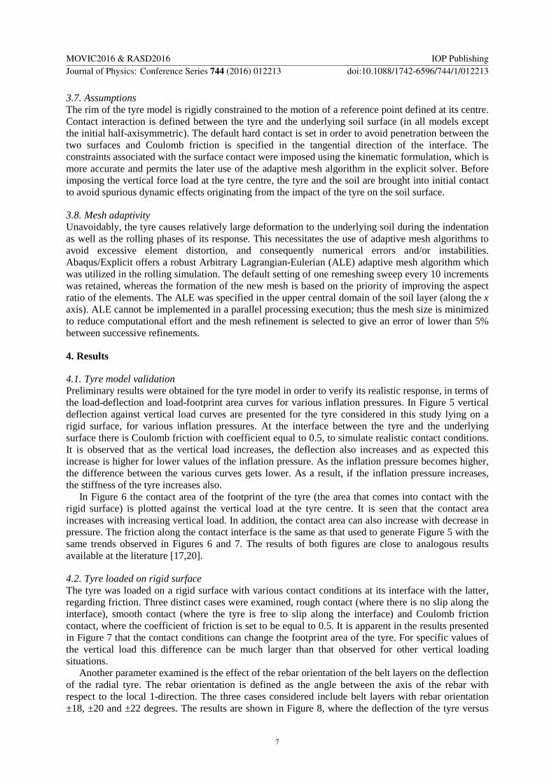
4.1. Tyre model validation Preliminary results were obtained for the tyre model in order to verify its realistic response, in terms of the load-deflection and load-footprint area curves for various inflation pressures. In Figure 5 vertical deflection against vertical load curves are presented for the tyre considered in this study lying on a rigid surface, for various inflation pressures. At the interface between the tyre and the underlying surface there is Coulomb friction with coefficient equal to 0.5, to simulate realistic contact conditions. It is observed that as the vertical load increases, the deflection also increases and as expected this increase is higher for lower values of the inflation pressure. As the inflation pressure becomes higher, the difference between the various curves gets lower. As a result, if the inflation pressure increases, the stiffness of the tyre increases also.
In Figure 6 the contact area of the footprint of the tyre (the area that comes into contact with the rigid surface) is plotted against the vertical load at the tyre centre. It is seen that the contact area increases with increasing vertical load. In addition, the contact area can also increase with decrease in pressure. The friction along the contact interface is the same as that used to generate Figure 5 with the same trends observed in Figures 6 and 7. The results of both figures are close to analogous results available at the literature [17,20].
4.2. Tyre loaded on rigid surface The tyre was loaded on a rigid surface with various contact conditions at its interface with the latter, regarding friction. Three distinct cases were examined, rough contact (where there is no slip along the interface), smooth contact (where the tyre is free to slip along the interface) and Coulomb friction contact, where the coefficient of friction is set to be equal to 0.5. It is apparent in the results presented in Figure 7 that the contact conditions can change the footprint area of the tyre. For specific values of the vertical load this difference can be much larger than that observed for other vertical loading situations.
Another parameter examined is the effect of the rebar orientation of the belt layers on the deflection of the radial tyre. The rebar orientation is defined as the angle between the axis of the rebar with respect to the local 1-direction. The three cases considered include belt layers with rebar orientation ±18, ±20 and ±22 degrees. The results are shown in Figure 8, where the deflection of the tyre versus
MOVIC2016 & RASD2016 IOP PublishingJournal of Physics: Conference Series 744 (2016) 012213 doi:10.1088/1742-6596/744/1/012213
7
the vertical load is plotted for various rebar orientations. We can see that by increasing the rebar orientation angle there is a decrease in the stiffness of the tyre since the vertical deflection increases.
Figure 5. Vertical deflection versus vertical load curves for various inflation pressures.
Figure 6. Contact area versus vertical load curves for various inflation pressures.
4.3. Tyre rolling on deformable soil
4.3.1. Effects of aspect ratio In Figure 9 the dimensionless sinkage of two deformable tyres with different aspect ratios rolling on soft soil is plotted against time. The two tyres have the same inflation pressure equal to 242kPa and both of them have an imposed slip ratio equal to 1%. Initially, the tyre is rolling over a very stiff segment of the underlying soil, and its sinkage remains low and almost constant. Afterwards, the tyre is travelling into the deformable soil domain and the sinkage increases, exhibiting a peak after a while. Finally, as the tyre approaches steady state conditions, the sinkage stabilises to a steady state value. The peak observed in the initial stage of rolling into the deformable soil is mainly due to the dynamic effects triggered due to the abrupt change in the soil properties. Following that, it is evident that the tyre with higher aspect ratio show the lower dimensionless sinkage, as is expected. The difference in sinkage is greater for the deformable soil than for the stiff soil area, and this justifies the fact that the largest contribution to the tyre sinkage originates from the deformable soil.
4.3.2. Steady state sinkage In Figure 10 the dimensionless vertical force versus the dimensionless steady state sinkage for a deformable tyre with aspect ratio b/d=0.33 is shown. Several simulations with different dimensionless vertical loads were performed to obtain the steady state dimensionless sinkage values. It is observed that there is an increase of the steady state sinkage as the loading force increases.
4.3.3. Effect of inflation pressure In Figure 11 the dimensionless sinkage during the simulation is presented for the case of a deformable tyre with aspect ratio equal to 0.33, loaded with force equal to 1.5γbd2. The results for two different inflation pressures are presented (120kPa and 242kPa). It is apparent that in the initial stage when the tyre rolls over the stiff region of the soil the dimensionless sinkage is smaller for the higher inflation pressure, while for the soft region the dimensionless sinkage becomes the largest for the higher inflation pressure. Apart from the dimensionless sinkage, the mean value of the dimensionless contact area of the tyre during its travel in the deformable soil domain is also plotted in the same figure. It is also observed that for higher inflation pressure, the contact area decreases, since the tyre stiffness is increased in this case. Contrary to the common intuition that for higher inflation pressure the tyre is exhibiting the optimum response, the opposite trend is observed in Figure 12. It is demonstrated in this
0
1
2
3
4
5
6
0 1 2 3 4 5 6 7 8 9
Ver
tical
Def
lect
ion
(cm
)
Vertical Load (kN)
80kPa160kPa200kPa242kPa
0
100
200
300
400
500
600
700
0 1 2 3 4 5 6 7 8 9
Cont
act a
rea
(cm
2 )Vertical Load (kN)
80kPa160kPa200kPa242kPa
MOVIC2016 & RASD2016 IOP PublishingJournal of Physics: Conference Series 744 (2016) 012213 doi:10.1088/1742-6596/744/1/012213
8

figure that by decreasing the inflation pressure of the tyre, the average value of the dimensionless sinkage decreases. The effect of the inflation pressure becomes less significant for the range between 160kPa and 200kPa, while on the other hand, when the inflation pressure of 242kPa is reduced by half, the effect is more pronounced.
Figure 7. Contact area versus vertical load for various friction conditions at the tyre – soil interface.
Figure 8. Deflection versus vertical load for various orientations of the rebar of the belt layers.
Figure 9. Dimensionless sinkage versus time for two values of the aspect ratio of the tyre.
Figure 10. Dimensionless vertical force versus dimensionless steady state sinkage for the case of b/d=0.33.
In Figure 13 the average ratio of the resistance force to vertical load is plotted versus the inflation
pressure of a towed deformable tyre with aspect ratio 0.33. The average value of the horizontal resistance force is taken for the time interval corresponding to the rolling of the tyre. It is seen that for small inflation pressures the non-dimensional resistance force decreases slightly as the inflation pressure increases. This trend results from the fact that as the inflation pressure increases, the contact area decreases, and therefore the soil accumulation in front of the tyre decreases. As the inflation pressure becomes higher (exceeding 220kPa in this case), the tyre stiffness increases, which for the given soil conditions leads to a rigid tyre behaviour with higher dimensionless sinkage, higher soil accumulation, and therefore higher rolling resistance. These two different tendencies invoke a resistance force minimum (which occurs for inflation pressure somewhat lower than 220kPa in the
0
50
100
150
200
250
300
350
400
450
0 1 2 3 4 5 6 7 8 9
Con
tact
are
a (c
m2 )
Vertical Load (kN)
160kPa, rough
160kPa, smooth
160kPa, μ=0.5
1.9
2.1
2.3
2.5
2.7
2.9
3.1
3 4 5 6 7
Def
lect
ion
(cm
)
Vertical Load (kN)
18
20
22
0
0.01
0.02
0.03
0.04
0.05
0.06
1 1.1 1.2 1.3 1.4 1.5 1.6 1.7
s/d
Time (sec)
b/d=0.33
b/d=0.42
0
0.5
1
1.5
2
2.5
3
0 0.02 0.04 0.06 0.08 0.1
Qv/γb
d2
s/d
MOVIC2016 & RASD2016 IOP PublishingJournal of Physics: Conference Series 744 (2016) 012213 doi:10.1088/1742-6596/744/1/012213
9

case shown in Figure 13). In Figure 14 the phenomenon of soil accumulation in front of the wheel is presented. It was assured in the analyses performed in this study that the ALE adaptive mesh algorithm used captured this phenomenon in a very satisfactory way.
Figure 11. Dimensionless sinkage and dimensionless contact area versus time for two values of the inflation pressure of the tyre, for the case of b/d=0.33 and Qv=1.5γbd2.
Figure 12. Inflation pressure versus average value of the dimensionless sinkage for the case of b/d=0.33 and Qv=1.5γbd2.
Figure 13. Average ratio of resistance force to vertical load for various inflation pressures.
Figure 14. Deformed configuration of the tyre – soil model developed in this study, in which the soil accumulation is apparent.
In Figure 15 the slip ratio of the deformable towed tyre with aspect ratio equal to 0.33 and vertical
load 1.5γbd2 is plotted versus the inflation pressure. It is observed that by reducing the inflation pressure, the slip ratio is also reduced, with different rate of decrease, depending on the pressure range and the soil conditions. For the given soil the biggest slip ratio decrease is observed for inflation pressure varying from 200kPa to 160kPa. In addition, a further decrease from 160kPa to 120kPa does not entail significant variation in the slip ratio, whilst at the same time as shown in Figure 13, the resi-stance force increases. The results presented in Figure 13 and 15 demonstrate a main tradeoff between the slip ratio and the bulldozing force. While minimum slip ratio accompanied with minimum resistance force is desired in vehicle dynamics, mainly for safety and economical reasons respectively, there is only one optimum (case-dependent) value of the inflation pressure which will satisfy both of these requirements.
0.005
0.01
0.015
0.02
0.025
0.03
0.035
0.04
0.045
0.05
0.02
0.025
0.03
0.035
0.04
0.045
0.05
0.055
0.06
1 1.2 1.4 1.6 1.8 2 2.2 2.4
CA
RE
A/(b
d)
s/d
Time (sec)
Sinkage, 120kPa
Sinkage, 242kPa
CAREA, 120kPa
CAREA, 242kPa100
120
140
160
180
200
220
240
260
0.0525 0.053 0.0535 0.054 0.0545 0.055
Infla
tion
Pres
sure
(kPa
)
(s/d)avg
0.1
0.11
0.12
0.13
0.14
0.15
0.16
0.17
0.18
0.19
0.2
120 140 160 180 200 220 240
Qh
/ Qv
Inflation Pressure (kPa)
MOVIC2016 & RASD2016 IOP PublishingJournal of Physics: Conference Series 744 (2016) 012213 doi:10.1088/1742-6596/744/1/012213
10
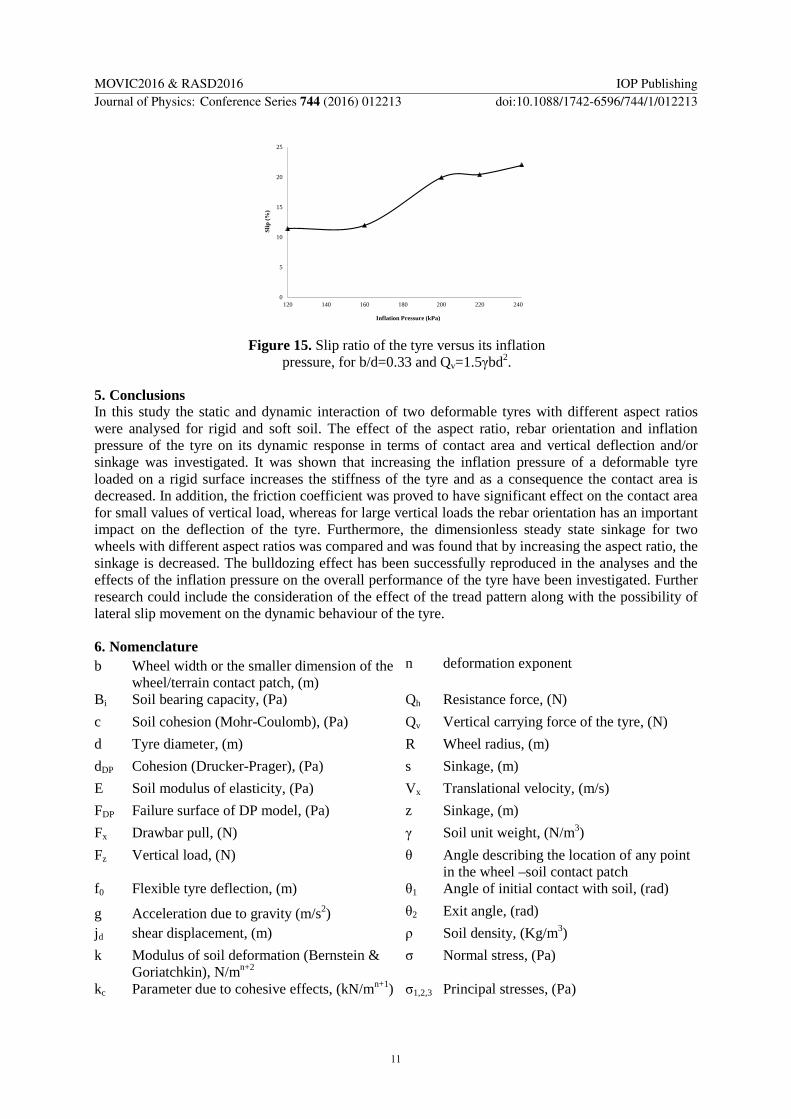
Figure 15. Slip ratio of the tyre versus its inflation
pressure, for b/d=0.33 and Qv=1.5γbd2.
5. Conclusions In this study the static and dynamic interaction of two deformable tyres with different aspect ratios were analysed for rigid and soft soil. The effect of the aspect ratio, rebar orientation and inflation pressure of the tyre on its dynamic response in terms of contact area and vertical deflection and/or sinkage was investigated. It was shown that increasing the inflation pressure of a deformable tyre loaded on a rigid surface increases the stiffness of the tyre and as a consequence the contact area is decreased. In addition, the friction coefficient was proved to have significant effect on the contact area for small values of vertical load, whereas for large vertical loads the rebar orientation has an important impact on the deflection of the tyre. Furthermore, the dimensionless steady state sinkage for two wheels with different aspect ratios was compared and was found that by increasing the aspect ratio, the sinkage is decreased. The bulldozing effect has been successfully reproduced in the analyses and the effects of the inflation pressure on the overall performance of the tyre have been investigated. Further research could include the consideration of the effect of the tread pattern along with the possibility of lateral slip movement on the dynamic behaviour of the tyre.
6. Nomenclature b Wheel width or the smaller dimension of the
wheel/terrain contact patch, (m) n deformation exponent
Bi Soil bearing capacity, (Pa) Qh Resistance force, (N) c Soil cohesion (Mohr-Coulomb), (Pa) Qv Vertical carrying force of the tyre, (N) d Tyre diameter, (m) R Wheel radius, (m) dDP Cohesion (Drucker-Prager), (Pa) s Sinkage, (m) E Soil modulus of elasticity, (Pa) Vx Translational velocity, (m/s) FDP Failure surface of DP model, (Pa) z Sinkage, (m) Fx Drawbar pull, (N) γ Soil unit weight, (N/m3) Fz Vertical load, (N) θ Angle describing the location of any point
in the wheel –soil contact patch f0 Flexible tyre deflection, (m) θ1 Angle of initial contact with soil, (rad)
g Acceleration due to gravity (m/s2) θ2 Exit angle, (rad) jd shear displacement, (m) ρ Soil density, (Kg/m3) k Modulus of soil deformation (Bernstein &
Goriatchkin), N/mn+2 σ Normal stress, (Pa)
kc Parameter due to cohesive effects, (kN/mn+1) σ1,2,3 Principal stresses, (Pa)
0
5
10
15
20
25
120 140 160 180 200 220 240
Slip
(%)
Inflation Pressure (kPa)
MOVIC2016 & RASD2016 IOP PublishingJournal of Physics: Conference Series 744 (2016) 012213 doi:10.1088/1742-6596/744/1/012213
11

Kd Shear deformation modulus, (m) τ Shear stress, Pa kz Kacigin & Guskov’s parameter, (N/m3) φ Soil friction angle (Mohr-Coulomb), (rad) kφ Parameter due to frictional effects, (kN/mn+2) ω Angular velocity, (rad/s) Acknowledgements This work was supported by Jaguar Land Rover and the UK-EPSRC grant EP/K014102/1 as part of the jointly funded Programme for Simulation Innovation.
References [1] Chiroux R.C., Foster Jr. W.A., Johnson C.E., Shoop S.A. and Raper R.L., 2005, Three-
dimensional finite element analysis of soil interaction with a rigid wheel, J. Applied Mathematics & Computation, 162, pp. 707-722.
[2] Bekakos C.A., Papazafeiropoulos G., O’Boy D.J. and Prins J., 2015, Dynamic response of rigid wheels on deformable terrains, Proc. 13th ISTVS European Conf., Rome, pp. 588-600.
[3] Bernstein R., 1913, Probleme zur experimentellen Motorplugmechanik, Der Motorwagen, 16, pp. 199-206.
[4] Goriatchkin, B.P., 1936, Theory and Manufacturing of Agricultural Machines, Moscow, USSR Goverment.
[5] Janosi, Z., Hanamoto, B., 1961, The analytical determination of drawbar pull as a function of slip for tracked vehicles in deformable soils. Proc. 1st Int. Conf. on the Mechanics of Soil-Vehicle Systems, Torino, Italy.
[6] Wong, J.Y. and Preston-Thomas, J., 1983, On the characterization of the shear stress-displacement relationship of terrain, Journal of Terramechanics, 19(4), pp. 225–234.
[7] Harnisch, C., Lach, B., Jakobs, R., Troulis, M., and Nehls, O., 2005, A new tyre–soil interaction model for vehicle simulation on deformable ground, Vehicle System Dynamics: International Journal of Vehicle Mechanics and Mobility, 43(s1), pp. 384–394.
[8] Kacigin, V.V., and Guskov, V.V., 1968, The basis of tractor performance theory, Journal of Terramechanics, 5(3).
[9] Hambleton, J. P. and Drescher, A., 2008, Modelling wheel-induced rutting in soils: Indentation. Journal of Terramechanics, 45(6), pp. 201–211.
[10] Hambleton, J. P. and Drescher, A., 2009, Modelling wheel-induced rutting in soils: Rolling. Journal of Terramechanics, 46(2), pp. 35–47.
[11] Lyasko, M., 2010, LSA model for sinkage predictions, Journal of Terramechanics, 47(1), 1–19. [12] Kölsch, C., 2000, Vertical vehicle dynamics on soft ground-investigations with FEM, FISITA
World Automotive Congress, pp. 1–8. [13] Fervers, C., 2004, Improved FEM simulation model for tire–soil interaction, Journal of
Terramechanics, 41(2-3), pp. 87–100. [14] Xia, K., 2011, Finite element modelling of tire/terrain interaction: Application to predicting soil
compaction and tire mobility, Journal of Terramechanics, 48, 113-123. [15] Seta, E., Kamegawa, T., and Nakajima, Y., 2003, Prediction of snow/tire interaction using
explicit FEM and FVM, Tire Science and Technology, TSTCA, 31(3), pp. 173–188. [16] Lee, J.H., 2009, A new indentation model for snow, Journal of Terramechanics, 46, pp. 1-13. [17] Lee, J.H., 2011, Finite element modelling of interfacial forces and contact stresses of pneumatic
tire on fresh snow for combined longitudinal and lateral slips, Journal of Terramechanics, 48, pp. 171-197.
[18] Choi, J.H, Cho, J.R., Woo, J.S., and Kim, K.W., 2012, Numerical investigation of snow traction characteristics of 3-D patterned tire, Journal of Terramechanics, 49, pp. 81-93.
[19] Nakashima, H., and Oida, A., 2004, Algorithm and implementation of soil-tyre contact analysis code based on dynamic FE-DE method, Journal of Terramechanics, 41, pp. 127-137.
[20] Shoop, S.A., 2001, Finite Element Modelling of Tire-Terrain Interaction, University of Michigan, Report number: ERDC/CRREL TR-01-16.
MOVIC2016 & RASD2016 IOP PublishingJournal of Physics: Conference Series 744 (2016) 012213 doi:10.1088/1742-6596/744/1/012213
12