pocketlogger™ · ecu tuning ... below you will find basic step by step procedures for getting...
TRANSCRIPT

PocketLOGGER™for
For use exclusively with Rtek7™ Stage 2 ECU Upgrade
Instruction Guide
Rtek FirmwareN332 Ver 1.1.2N326 Ver 1.0.0N351 Ver 1.0.0
PocketLOGGER Ver 2.0.0
digital tuning, inc.23021 N. 15th Ave. Suite 205
Phoenix, AZ 85027623-444-2378
© 2008 digital tuning, inc. All Rights Reserved

4/18/07

WARNING WARNING WARNING WARNING WARNINGOnly YOU are responsible for making sure you engine gets enough fuel!!!The Rtek7 is not a magic ECU that will control any setup you have. It will
require that you make adjustments for your particular setup BEFORE putting a load on the engine, or catastrophic engine failure will result.
The Rtek7 Stage 2 and PocketLOGGER for RX7 make for a very powerful engine management tuning tool. With power comes responsibility. It is very easy to make changes via the PocketLOGGER software that will
be detrimental to your engine. We highly suggest you completely read this manual as well as have a grasp on basic tuning procedures and goals before attempting to make any adjustments.
Engine monitoring with a wideband O2 is highly recommended.
WARNING!TUNING SHOULD BE PERFORMED ONLY BY A TECHNICIAN WHO FULLY
UNDERSTANDS THE VEHICLE'S FUEL MANAGEMENT AND IGNITION TIMING REQUIREMENTS.
DIGITAL TUNING, INC. IS NOT LIABLE FOR ANY AND ALL DAMAGES CAUSED BY IMPROPER INSTALLATION OR TUNING.
• Completely read this manual before attempting to make any adjustments.• Improper use of this product can cause severe engine damage. • Always use the proper Air/Fuel Ratio meter when making fuel adjustments.• You should have a thorough understand of engine management, tuning
procedures, and target A/F ratios before attempting to use the Rtek7 ECU • Certain Rtek7 parameters need to be set up BEFORE you run the engine.• Disconnect any external fuel control or FCD before running the Rtek7
ECU, or zero out any external fuel control if you leave it connected.• The Rtek7 Stage 2 ECU is for off-road use only.• Installation and use of this product should only be performed by a trained
automotive specialist or damage to the ECU or vehicle could result.• Never use PocketLOGGER while the vehicle is moving.• Never tune the Rtek7 on public streets or highways.• Keep all cables clear of the drivers feet and away from seat rails or other
places it could be damaged.
WARNING WARNING WARNING WARNING WARNING


Table of ContentsChapter 1: Quick-Start
Software Installation..........................................................................................................................8Rtek7 Initial Startup Procedures............................................................................................................8Tuning.........................................................................................................................................8Datalogging...................................................................................................................................9Viewing Saved Logs.........................................................................................................................9
Chapter 2: Palm Software SetupRequirements...............................................................................................................................10Getting the Software........................................................................................................................10Software Installation........................................................................................................................10Running for the First Time.................................................................................................................11Accessing Menus...........................................................................................................................11
Chapter 3: Getting StartedRtek7 ECU Feature Overview.............................................................................................................12
Fuel Correction Table.............................................................................................................12Timing Table.......................................................................................................................12Staging RPMs......................................................................................................................12Injector Presets....................................................................................................................13Datalogging........................................................................................................................13Inputs...............................................................................................................................13Outputs.............................................................................................................................13Crank Fueling......................................................................................................................13
Initial Rtek7 Startup Procedures...........................................................................................................13ECU Installation....................................................................................................................13Compatibility with Other Hardware...............................................................................................13Establishing Connection with ECU...............................................................................................14Troubleshooting Connection Problems..........................................................................................14Setup Required Prior to Running the Engine the First Time...................................................................14
Chapter 4: Engine Tuning with the Rtek7ECU Setup..................................................................................................................................15
Displaying the ECU Setup Screen...............................................................................................15ECU Firmware Information........................................................................................................15Injectors Tab.......................................................................................................................15Staging Tab........................................................................................................................16
Sec. Inj................................................................................................................16
VDI....................................................................................................................16
6PI.....................................................................................................................16Inputs Tab..........................................................................................................................17
Variable Resistor......................................................................................................17
Pin 3F Input...........................................................................................................17
Atmospheric Pressure Sensor........................................................................................18Outputs Tab........................................................................................................................18General Tab........................................................................................................................19Idle Tab.............................................................................................................................19
Variable Resistor Adjustment.........................................................................................19Starting Tab........................................................................................................................19
ECU Tuning.................................................................................................................................20Fuel Map............................................................................................................................20
Table View............................................................................................................20
Bargraph View........................................................................................................21
3D Graph View........................................................................................................21Timing Map.........................................................................................................................22
Load...................................................................................................................22
Accessing Timing Screens...........................................................................................22

Split Map..............................................................................................................23
Table View............................................................................................................23
Map View..............................................................................................................23Loading and Saving ECU Configurations.................................................................................................24
Saving an ECU Configuration....................................................................................................25Loading an ECU Configuration...................................................................................................25
Chapter 5: DataloggingDatalogging Screens.......................................................................................................................26
Graph View.........................................................................................................................26Number View.......................................................................................................................26
Select Parameters Screen.................................................................................................................27Parameters.........................................................................................................................27Table Indexes......................................................................................................................28Quick Selects......................................................................................................................28Programming Quick Selects......................................................................................................28
Trigger.......................................................................................................................................28Logging Data................................................................................................................................29Using a Trigger to Start Datalogging......................................................................................................29Alarm.........................................................................................................................................30Viewing Saved Log List.....................................................................................................................30
Go Back............................................................................................................................30Select Parameters.................................................................................................................30Log Info.............................................................................................................................30Display Note........................................................................................................................30Rename............................................................................................................................30Delete...............................................................................................................................30View Log............................................................................................................................30
Viewing a Saved Log.......................................................................................................................31Navigating a log....................................................................................................................31Using the Navigation Slider.......................................................................................................32Zooming in and out................................................................................................................32Viewing Exact Parameter Values.................................................................................................32Locking a Graph...................................................................................................................32
Datalogging Preferences...................................................................................................................33Tap anywhere to start log.........................................................................................................335 Second beep while logging.....................................................................................................33Metric and Imperial Pushbuttons.................................................................................................33Setup Ext. Sensor.................................................................................................................33
Chapter 6: External Sensors and DevicesConnecting External Sensors to ECU Inputs.............................................................................................34
Pinout Diagrams...................................................................................................................34Using the Variable Resistor Input................................................................................................35Using the ATP Sensor Input......................................................................................................35Using Pin 3F as Input.............................................................................................................36
Configuring External Sensor Scaling......................................................................................................36Accessing the External Sensor Scaling Screen.................................................................................36Configuring Sensor Scaling.......................................................................................................36
Calculator.............................................................................................................37Tweaking the Display Values.....................................................................................................37
Controlling External Devices with the ECU...............................................................................................38Pinout Diagrams...................................................................................................................38Electrical Characteristics of the ECU Output....................................................................................38Wiring...............................................................................................................................39Configuring the RPM Threshold..................................................................................................39
Chapter 7: DiagnosticsDiagnostic Screens.........................................................................................................................40
Reading Error Codes..............................................................................................................40

Digital Input and Output Status...................................................................................................40Appendix I: PocketLOGGER Software Screen Tree...................................................................................................41
Appendix II: END-USER LICENSE AGREEMENT FOR POCKETLOGGER™ for Rtek7............................................................42
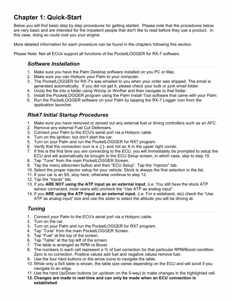
Chapter 1: Quick-Start Below you will find basic step by step procedures for getting started. Please note that the procedures below are very basic and are intended for the impatient people that don't like to read before they use a product. In this case, doing so could cost you your engine.
More detailed information for each procedure can be found in the chapters following this section.
Please Note: Not all ECUs support all functions of the PocketLOGGER for RX-7 software.
Software Installation1. Make sure you have the Palm Desktop software installed on you PC or Mac.2. Make sure you can Hotsync your Palm to your computer.3. The PocketLOGGER for RX-7's was emailed to you when your order was shipped. The email is
generated automatically. If you did not get it, please check your bulk or junk email folder.4. Unzip the file into a folder using Winzip or WinRar and then navigate to that folder.5. Install the PocketLOGGER program using the Palm Install Tool software that came with your Palm.6. Run the PocketLOGGER software on your Palm by tapping the RX-7 Logger icon from the
application launcher.
Rtek7 Initial Startup Procedures1. Make sure you have removed or zeroed out any external fuel or timing controllers such as an AFC.2. Remove any external Fuel Cut Defensers.3. Connect your Palm to the ECU's serial port via a Hotsync cable.4. Turn on the ignition, but don't start the car.5. Turn on your Palm and run the PocketLOGGER for RX7 program.6. Verify that the connection icon is a -[ ]- and not an X in the upper right corner.7. If this is the first time you are connecting to the ECU, you will immediately be prompted to setup the
ECU and will automatically be brought to the ECU Setup screen, in which case, skip to step 10.8. Tap “Tune” from the main PocketLOGGER Screen.9. Tap the menu silkscreen button and then “ECU Setup”. Tap the “Injector” tab.10. Select the proper injector setup for your vehicle. Stock is always the first selection in the list.11. If your car is an S5, stop here, otherwise continue to step 12.12. Tap the “Inputs” tab.13. If you ARE NOT using the ATP input as an external input, (i.e. You still have the stock ATP
sensor connected, most users will) uncheck the “Use ATP as analog input”.14. If you ARE using the ATP input as an external input, (i.e. For a wideband, etc) check the “Use
ATP as analog input” box and use the slider to select the altitude you will be driving at.
Tuning1. Connect your Palm to the ECU's serial port via a Hotsync cable.2. Turn on the car.3. Turn on your Palm and run the PocketLOGGER for RX7 program.4. Tap “Tune” from the main PocketLOGGER Screen.5. Tap “Fuel” at the top of the screen.6. Tap “Table” at the top left of the screen.7. The table is arranged as RPM vs Boost.8. The numbers in each cell represent a % of fuel correction for that particular RPM/Boost condition.
Zero is no correction. Positive values add fuel and negative values remove fuel.9. Use the four hard buttons or the arrow icons to navigate the table.10. While only a 5x5 table is shown, the table size varies depending on the ECU and will scroll if you
navigate to an edge.11. Use the hard Up/Down buttons (or up/down on the 5-way) to make changes in the highlighted cell.12. Changes are made in real-time and can only be made when an ECU connection is
established

Datalogging1. Connect your Palm to the ECU's serial port via a Hotsync cable2. Turn on the car3. Turn on your Palm and run the PocketLOGGER for RX7 program4. Tap “Log” from the main screen5. Tap the wrench icon, or press the Page Up hard button to bring you to the Parameter Select screen6. Select the Parameters you wish to log and tap OK, or press the Page Up hard button again7. Verify that the icon in the upper right corner is a -[ ]- and not an X. If it is an X, check your
connection. If it is -[ ]- then data should be being displayed8. Use the Page Down hard button or icons to toggle between the Graph and Number view screens9. When ready to datalog, tap the Go button. It changes to “Stop” and flashes. Data is being stored.10. If you datalog for at least 5 seconds, the data collected is automatically saved with a time and date
stamp.
Viewing Saved Logs1. Viewing saved logs can be done at any time. The Palm does not need to be connected to the car2. From the main screen, tap “View”3. You will see a list of saved logs. Select the log you wish to view at tap the magnifying glass icon at
the bottom right of the screen.4. Use the arrows to navigate. Use the hard up/down buttons to zoom in and out.5. Tap the screen or drag the stylus on the screen to see parameter values at that exact point
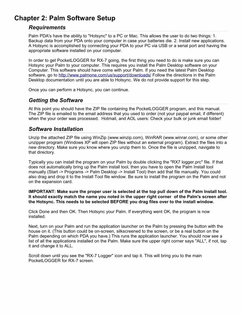
Chapter 2: Palm Software SetupRequirementsPalm PDA's have the ability to "Hotsync" to a PC or Mac. This allows the user to do two things: 1. Backup data from your PDA onto your computer in case your batteries die. 2. Install new applications. A Hotsync is accomplished by connecting your PDA to your PC via USB or a serial port and having the appropriate software installed on your computer.
In order to get PocketLOGGER for RX-7 going, the first thing you need to do is make sure you can Hotsync your Palm to your computer. This requires you install the Palm Desktop software on your Computer. This software should have come with your Palm. If you need the latest Palm Desktop software, go to http://www.palmone.com/us/support/downloads/ Follow the directions in the Palm Desktop documentation until you are able to Hotsync. We do not provide support for this step.
Once you can perform a Hotsync, you can continue.
Getting the SoftwareAt this point you should have the ZIP file containing the PocketLOGGER program, and this manual. The ZIP file is emailed to the email address that you used to order (not your paypal email, if different) when the your order was processed. Hotmail, and AOL users: Check your bulk or junk email folder!
Software InstallationUnzip the attached ZIP file using WinZip (www.winzip.com), WinRAR (www.winrar.com), or some other unzipper program (Windows XP will open ZIP files without an external program). Extract the files into a new directory. Make sure you know where you unzip them to. Once the file is unzipped, navigate to that directory.
Typically you can install the program on your Palm by double clicking the "RX7 logger.prc" file. If that does not automatically bring up the Palm install tool, then you have to open the Palm Install tool manually (Start -> Programs -> Palm Desktop -> Install Tool) then add that file manually. You could also drag and drop it to the Install Tool file window. Be sure to install the program on the Palm and not on the expansion card.
IMPORTANT: Make sure the proper user is selected at the top pull down of the Palm Install tool. It should exactly match the name you noted in the upper right corner of the Palm's screen after the Hotsync. This needs to be selected BEFORE you drag files over to the install window.
Click Done and then OK. Then Hotsync your Palm. If everything went OK, the program is now installed.
Next, turn on your Palm and run the application launcher on the Palm by pressing the button with the house on it. (This button could be on-screen, silkscreened to the screen, or be a real button on the Palm depending on which PDA you have.) This runs the application launcher. You should now see a list of all the applications installed on the Palm. Make sure the upper right corner says "ALL", if not, tap it and change it to ALL.
Scroll down until you see the "RX-7 Logger" icon and tap it. This will bring you to the main PocketLOGGER for RX-7 screen.

Running for the First Time
When you first run the PocketLOGGER software you will see the following main screen.
Accessing Menus
If you tap the silkscreen menu button you will see the following menu pop up:
The Menu button is used throughout the program to access different options pertaining to the screen you are on.
PreferencesMake changes to the program preferences.
RegisterSee your registration information
AboutView program information.
LogView and store real time sensor data.
ViewLoad and view datalogs that were saved.
TuneAllow you to make fuel, timing, and other adjustments to your ECU.
DiagCheck error codes and ECU's digital inputs and outputs.
Menu ButtonThe menu button is down here. Or the third icon from the left on a T3. It looks just like the icon shown here.

Chapter 3: Getting StartedRtek7 ECU Feature Overview
WARNINGThe Rtek7 Stage 2 ECU and PocketLOGGER for RX7 is a very powerful engine management and tuning tool. With power comes responsibility. You are responsible for making sure your engine gets enough fuel. It is very easy to make changes to your Rtek7 ECU via the PocketLOGGER software that will be detrimental to your engine. We highly suggest you completely read the tuning section of this manual before attempting to make any adjustments.
DIGITAL TUNING WILL BE IN NO WAY RESPONSIBLE FOR DAMAGE TO YOUR ENGINE DUE TO IMPROPER TUNING.
Overview of Rtek7 Stage 2 ECU CapabilitiesThe Rtek7 Stage 2 ECU gives the user the ability to modify both fuel and timing without tricking the ECU in any way like using external hardware does. The fuel and timing changes are done within the factory ECU maintaining the drivability of the factory ECU while adding the flexibility of a stand-alone without having to rewire the whole car.
Fuel Correction TableFuel adjustments can be made using the Fuel Correction Map. The map is arranged as an RPM vs. Boost table with each cell being a correction factor the user can specify. Every engine cycle, the ECU calculates the fuel required then, based on the current boost and RPM, looks up the user-set correction factor in the fuel correction map. This correction is applied to the result of the fuel calculation. The map size and adjustment range varies depending on ECU type and version.
Timing TableTiming adjustments are made to the actual timing maps. In the PocketLOGGER Software, there are two timing maps, one for leading and one for trailing. Each map is arranged as either a Load or Boost versus RPM table with each cell being the actual timing value in degrees. Every engine cycle, the ECU uses the current load and RPM to lookup the timing value in the map. The user can directly change these values. The map size varies depending on ECU type and version.
Staging RPMsStaging RPMs are RPM points in which the ECU will trigger various events. The Rtek7 ECU gives you the ability to adjust the RPM in which these events occur instead of being set at the factory.
12 | Getting Started : Rtek7 ECU Feature Overview
Car S4 TII S4 TII S4 NA S5 NAECU N332 N332 N326 N351
Firmware 1.0.x 1.1.x 1.0.x 1.0.xFuel Correction Map
Size 10x10 14x14 14x14 18x14Adj Range ± 15% ± 37% ± 50% ± 50%
Timing MapSize 20x19 20x19 21x19 15x19
Adj Range Full Full Full FullStaging RPMs
Secondaries Yes Yes Yes YesVDI No No No Yes6PI No No No Yes
General Purpose InputsATP Yes Yes Yes No
Var Res No Yes Yes NoPin 3F No No No Yes
RPM Activated OutputsEGR No Yes Yes NoAWS No No No Yes
Injector Presets460 / 460 No No Yes Yes460 / 550 No No Yes Yes460 / 720 No No Yes Yes550 / 550 Yes Yes Yes Yes550 / 720 Yes Yes No No720 / 720 Yes Yes No No
Misc.Crank Fuel No Yes No No
Idle Fuel Adj. No Yes Yes No

Injector PresetsThe Rtek7 ECU has injector presets that can be selected if larger than stock injectors are installed. This will automatically adjust the fuel delivery to compensate for the additional fuel the larger injectors deliver. This correction is done in addition to any correction done in the Fuel Correction Table. Other injector sizes can be used, but the Rtek7 ECU will not fully compensate for them.
DataloggingThe PocketLOGGER software is capable of reading and storing engine data from the ECU. The stored datalogs can be viewed at a later time either on the Palm or exported for viewing on a PC.
InputsThe Rtek7 ECU adds the ability to reassign certain stock sensor inputs for use as a loggable general 0-5V input. This is useful for connecting a wideband O2 or other 0-5v sensor to the Rtek7 ECU so you can log sensor values along with all the other parameters the Rtek7 allows you to log.
OutputsMuch like the inputs, the Rtek7 ECU can utilized an existing ECU output for use by the user as an RPM activated output. The user can set the RPM at which it activates from within the software.
Crank FuelingWhen you have larger primary injectors, flooding while starting can be a problem. The Rtek7 ECU addresses this problem by allowing the user to control the Cranking Fuel vs Temperature map. This enables the user to adjust the amount of fuel that is injected while the engine is cranking.
Initial Rtek7 Startup Procedures
ECU InstallationIf you got this far you should have an RX-7 ECU modified with Rtek7 Stage 2. The ECU should be installed in the car in reverse order of it's removal. You will notice there is a wire with a DB9 connector now exiting the ECU chassis. You will need to plug your Palm's Hotsync cable into this connector in order to make changes to the ECU's settings. This wire should be run in a safe manner to a place that can be easily accessed, but away from any place that it could get kicked, tugged, stepped on, run over, caught in the seat rails, or otherwise damaged.
Compatibility with Other HardwareIt is highly recommended that when using the Rtek7 Stage 2 ECU you remove:
1. Any external fuel controllers such as an AFC2. Any external Fuel Cut Defensers3. Any external timing controller
These items are no longer needed as the Rtek7 has the functionality to replace these items. Keep in mind that these units go 'in-line' with the factory harness and removal of them requires the factory wiring to be reconnected.
Getting Started : Initial Rtek7 Startup Procedures | 13
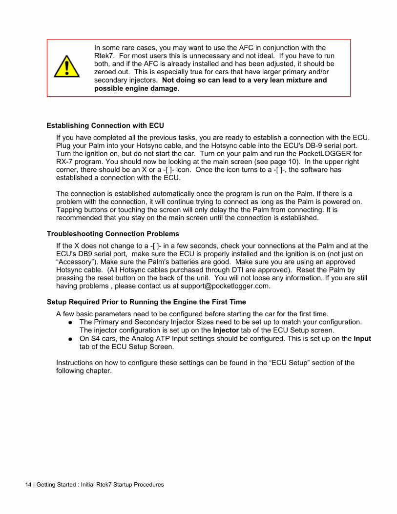
In some rare cases, you may want to use the AFC in conjunction with the Rtek7. For most users this is unnecessary and not ideal. If you have to run both, and if the AFC is already installed and has been adjusted, it should be zeroed out. This is especially true for cars that have larger primary and/or secondary injectors. Not doing so can lead to a very lean mixture and possible engine damage.
Establishing Connection with ECUIf you have completed all the previous tasks, you are ready to establish a connection with the ECU. Plug your Palm into your Hotsync cable, and the Hotsync cable into the ECU's DB-9 serial port. Turn the ignition on, but do not start the car. Turn on your palm and run the PocketLOGGER for RX-7 program. You should now be looking at the main screen (see page 10). In the upper right corner, there should be an X or a -[ ]- icon. Once the icon turns to a -[ ]-, the software has established a connection with the ECU.
The connection is established automatically once the program is run on the Palm. If there is a problem with the connection, it will continue trying to connect as long as the Palm is powered on. Tapping buttons or touching the screen will only delay the the Palm from connecting. It is recommended that you stay on the main screen until the connection is established.
Troubleshooting Connection ProblemsIf the X does not change to a -[ ]- in a few seconds, check your connections at the Palm and at the ECU's DB9 serial port, make sure the ECU is properly installed and the ignition is on (not just on “Accessory”). Make sure the Palm's batteries are good. Make sure you are using an approved Hotsync cable. (All Hotsync cables purchased through DTI are approved). Reset the Palm by pressing the reset button on the back of the unit. You will not loose any information. If you are still having problems , please contact us at [email protected].
Setup Required Prior to Running the Engine the First TimeA few basic parameters need to be configured before starting the car for the first time.
● The Primary and Secondary Injector Sizes need to be set up to match your configuration. The injector configuration is set up on the Injector tab of the ECU Setup screen.
● On S4 cars, the Analog ATP Input settings should be configured. This is set up on the Input tab of the ECU Setup Screen.
Instructions on how to configure these settings can be found in the “ECU Setup” section of the following chapter.
14 | Getting Started : Initial Rtek7 Startup Procedures

Chapter 4: Engine Tuning with the Rtek7
All the screens that pertain to making changes to the ECU are accessed by tapping the “Tune” button from the main PocketLOGGER screen. From there, you can view and adjust fuel and timing, make changes to the ECU's configuration, load and save complete ECU setups, as well as reset the ECU to it's factory settings. Please carefully read the following sections before attempting to make any changes.
ECU SetupThe ECU Setup screen allows you to configure various settings of the Rtek7 ECU as well as provide details on the Rtek7 firmware that is installed in your ECU. Changes made in the ECU Setup screen are sent to the ECU immediately.
Displaying the ECU Setup ScreenFrom the main screen, tap the “Tune” button. Tap the Menu silkscreen button, and then “ECU Setup”. The Rtek7 ECU Setup screen should now be displayed. The ECU Setup screen has several tabs which group options together. You can change tabs by simply tapping the tab you want. Once you are done configuring the ECU, tap the OK button to return to the previous Tune screen.
ECU Firmware InformationAt the top of the ECU Setup screen, you will see the ECU type, the version of the Rtek7 firmware installed in your ECU, and the serial number of your Rtek7 ECU.
Injectors TabTapping the Injectors tab will bring you to the injector preselect screen. The Rtek7 ECU has several injector presets the user can select to automatically compensate for larger than stock injectors . The injector sizes and number of configurations will vary depending on the ECU type and version. A list of available presets for each ECU type can be found in Chapter 3.
When you install larger primary and/or secondary injectors, they inject a larger amount of fuel for a given pulse width. A stock ECU is not aware of the size of the injectors that you are running. It assumes they are the stock size so it will pulse the larger injectors like they are stock. This injects more fuel than needed and you typically need to use an external fuel controller to lean out the mixture.
The Rtek7 injector configuration presets tell the ECU what injectors you are running. This will cause the ECU to factor in the larger injectors when it makes it's fuel calculation. This will reduce the pulse width, compensating for the larger injectors, eliminating the need to manually tune to lean them out.
It is very important to select the proper injector configuration! Selecting the wrong injector preset could lead to a lean condition and result in engine failure. If you do not know what injectors you have installed, either talk to someone that would, or leave it set it to first option (stock).
Engine Tuning with the Rtek7 : ECU Setup | 15

You can run any injector configuration you wish. It does not need to match the presets exactly. If you are running injector sizes other than the listed configurations, then pick the configuration that is LESS than your setup.
For example, if you are running 650cc primaries and 720cc secondaries on an S4 TII ECU, then select the 550/720 setup, as 550 is less than 650. If you select the 720/720 setup, you will run lean as the ECU is expecting 720 primaries. If you are unsure of which configuration you should pick for your setup, please contact us.
To change the Injector configuration, simply click the checkbox next to the appropriate injector combination. A warning will pop up reminding you that the wrong injector configuration could lead to engine damage. The first configuration in the list is always the stock configuration.
Staging TabThe Staging tab has the controls to adjust several RPM based events. Any staging RPM can be adjusted simply by dragging the slider control to the desired RPM. The ECU is not updated until you let go of the slider control.
Sec. Inj.The Secondary Staging RPM is the minimum RPM in which the ECU will turn on the secondary injectors. All ECUs support this adjustment.
The factory ECU's staging point is set to 3800 rpm which works well for a stock setup. When mods are made such as intake, exhaust, or porting, the increased airflow can push fueling requirements beyond what the stock ECU and stock primary injectors can deliver. This causes the engine to start running lean until the secondaries are turned on. Lowering the staging point can help eliminate this leaning as can using larger than stock primary injectors. The Rtek7 allows either or both methods to be used.
Ideally, the transition point should be set to an rpm that is low enough to avoid the lean spot. On a stock turbo setup with 550cc (stock) primaries, the following can be used as guidelines:
• under 8psi: stock setting• 8-10psi: lower to approx 3500• 10-12psi: lower to approx 3300
The above are guidelines, every engine will be different. Ideally, a wideband should be used to determine the correct staging point for your vehicle.
The following two options are only available on S5 NA cars.
VDIVariable Dynamic Intake (VDI) staging RPM is the minimum RPM at which the ECU will activate the VDI actuator. Stock setting is 5312 RPM.
6PIOn S5 NA vehicles, the 6 port intake (6PI) actuators are controlled by the ECU. The 6PI staging
16 | Engine Tuning with the Rtek7 : ECU Setup
RPM is the minimum RPM at which the ECU will activate the 6PI actuators. Stock setting is 3936 RPM. For a stock S5, the stock settings are good choices. If you have intake/exhaust mods or a ported engine you may want to change the settings. Typically they would be changed to activate at lower RPMs than stock. Testing on a dyno would reveal the best settings for your vehicle.
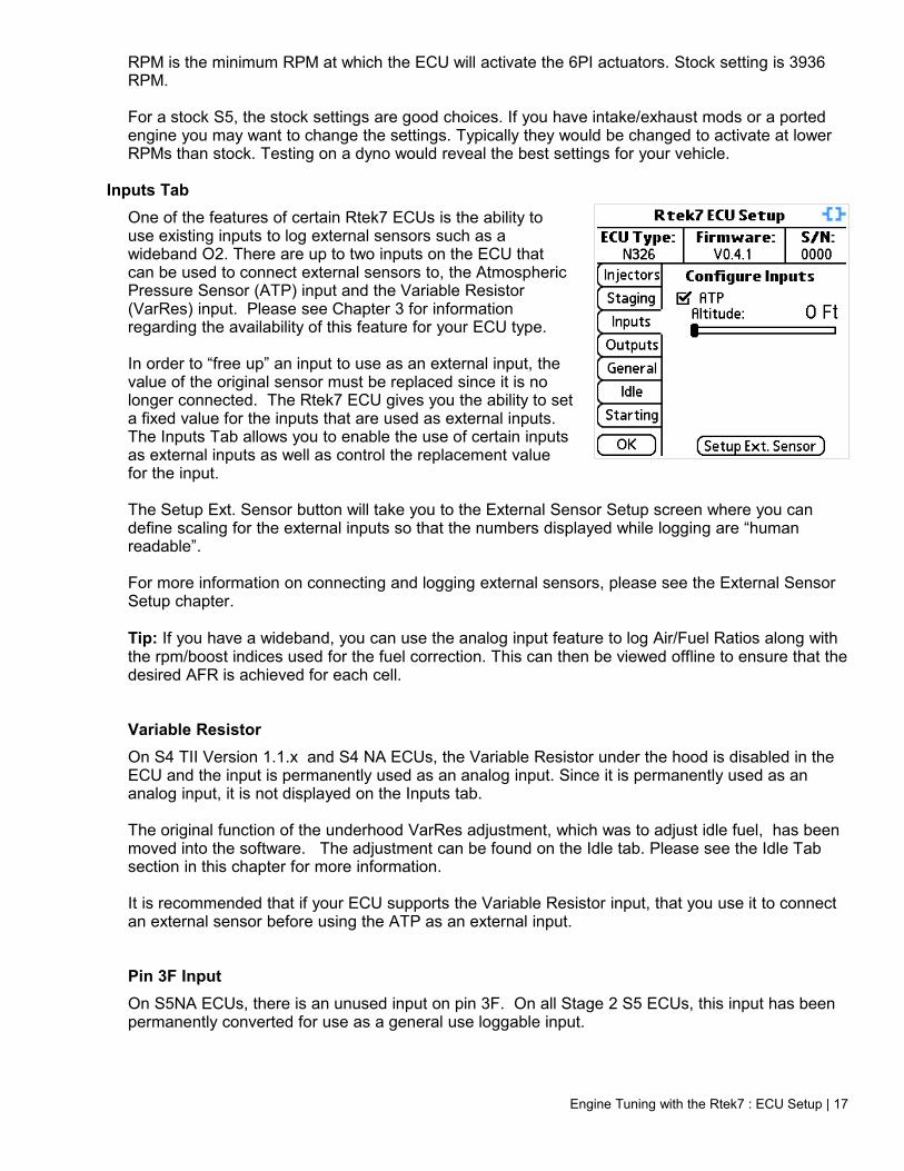
Inputs TabOne of the features of certain Rtek7 ECUs is the ability to use existing inputs to log external sensors such as a wideband O2. There are up to two inputs on the ECU that can be used to connect external sensors to, the Atmospheric Pressure Sensor (ATP) input and the Variable Resistor (VarRes) input. Please see Chapter 3 for information regarding the availability of this feature for your ECU type.
In order to “free up” an input to use as an external input, the value of the original sensor must be replaced since it is no longer connected. The Rtek7 ECU gives you the ability to set a fixed value for the inputs that are used as external inputs. The Inputs Tab allows you to enable the use of certain inputs as external inputs as well as control the replacement value for the input.
The Setup Ext. Sensor button will take you to the External Sensor Setup screen where you can define scaling for the external inputs so that the numbers displayed while logging are “human readable”.
For more information on connecting and logging external sensors, please see the External Sensor Setup chapter.
Tip: If you have a wideband, you can use the analog input feature to log Air/Fuel Ratios along with the rpm/boost indices used for the fuel correction. This can then be viewed offline to ensure that the desired AFR is achieved for each cell.
Variable ResistorOn S4 TII Version 1.1.x and S4 NA ECUs, the Variable Resistor under the hood is disabled in the ECU and the input is permanently used as an analog input. Since it is permanently used as an analog input, it is not displayed on the Inputs tab.
The original function of the underhood VarRes adjustment, which was to adjust idle fuel, has been moved into the software. The adjustment can be found on the Idle tab. Please see the Idle Tab section in this chapter for more information.
It is recommended that if your ECU supports the Variable Resistor input, that you use it to connect an external sensor before using the ATP as an external input.
Pin 3F InputOn S5NA ECUs, there is an unused input on pin 3F. On all Stage 2 S5 ECUs, this input has been permanently converted for use as a general use loggable input.
Engine Tuning with the Rtek7 : ECU Setup | 17
Atmospheric Pressure SensorOne of the sensors the ECU uses to calculate fuel delivery is an Atmospheric Pressure sensor, or ATP. The ATP sensor measures changes in atmospheric pressure which is a direct result of changes in altitude. Altitude changes affect the density of the air being ingested by the car. At high altitude, the air is less dense, so it has less oxygen, and therefore requires less fuel.
We found the amount of change to the final fuel delivery calculation was quite minute for the average driver as most people do not drive from sea level to the top of 5000ft mountains on a regular basis. By internally replacing the sensor's value with a fixed value, we could free up the analog input that the ATP sensor normally connected to. This input can then be connected to other sensors such as the 0-5v output of a wideband o2 sensor and can be logged with the PocketLOGGER software making it very useful.
This option is selected by default with an elevation of sea level for safety reasons. If you had, for example, a wideband o2 connected to the ATP input and you forgot to select “Use ATP as analog input” after an ECU reset, the ECU would assume the sensor on the ATP input is the actual ATP sensor. This would cause the ECU to think the car is making drastic changes in elevation and will adjust the fueling accordingly, possibly leading to a lean condition. For this reason, “Use ATP as analog input” is selected by default after a reset. The ECU will ignore the ATP input, even if there is an ATP sensor connected, and will assume sea level fueling. For proper operation of the ATP sensor if it is still connected, you must unselect the checkbox.
By checking the “Use ATP as analog input” checkbox, this tells the ECU to not use the ATP sensor input for fuel calculations but use a fixed value instead. The altitude slider is used to adjust the fixed value the ECU will use instead of the ATP sensor. Simply adjust the slider so the altitude equals the altitude of where you drive. Selecting a lower altitude than your actual altitude will cause the engine to run rich, and choosing a higher altitude than your actual will cause the engine to run lean. For this reason, it is advisable to always set the altitude slider to the minimum altitude you expect to drive.
It is important to note that if you normally drive at a high altitude and decide to take a trip down to the coast, as you descend, you car will run leaner and leaner. If you plan to use this feature, it is very important that you remember to adjust the altitude slider any time you plan on driving outside of your normal area.
You can change the units that the altitude is display in by going to the Preferences menu from the main screen. (See Preferences section in the Datalogging Chapter)
Not all ECU types support using the ATP input as an external input.
It is recommended that if your ECU supports the Variable Resistor input, that you use it before using the ATP as an external input.
Outputs TabSome ECUs have the option to use an existing output as an RPM controlled output. Depending on the ECU type and version, this may be the EGR output or the AWS output. On the Outputs Tab, there is a checkbox to enable the RPM control of the output. Check the checkbox to enable it and use the slider to adjust the RPM threshold at which the output should be activated.
For more information on connecting external devices, please see the External Sensors and Devices chapter.
18 | Engine Tuning with the Rtek7 : ECU Setup

General TabAll ECUs have a “Reset ECU” button on this tab. If at any point you wish to return the entire ECU back to stock, you can do so by tapping the Reset ECU button. A box will pop up a warning giving you one last chance to cancel before you reset the whole ECU back to the default settings. This includes zeroing out the Fuel correction map, restoring both the Leading and Trailing maps back to stock, resetting the VE map to all 100%, setting the injector setup and the Staging RPM to stock and turning on the “Use ATP as analog input”. This action cannot be undone.
Some ECUs support AFM Removal mode. To enable this mode, simply check the checkbox. This will allow you to run without an Airflow meter. If your ECU does not support No AFM Mode, the checkbox will not appear.
Idle TabThe PocketLOGGER software can walk you though setting up the idle RPM and fueling step by step. This is also where you can adjust the “virtual” variable resistor. Checking the “Set Initial Set Coupler” checkbox will put the ECU into idle setup mode, if your ECU supports it.
When you check the Set Initial Set Coupler checkbox, the five step walkthrough will start. Use the “Prev” and “Next” to change steps. By following the five steps you will be guided through the idle setup as per the factory service manual.
Variable Resistor AdjustmentStep 4 allows you to adjust the idle fuel. The Variable Resistor under the hood that used to adjust idle fuel is no longer used. Instead the Variable Resistor input is permanently set as an external input you can use for logging other sensors. The action of adjusting the Variable Resistor to set idle fuel is now adjusting the slider in step four.
Starting TabThe Starting tab displays the Cranking Fuel map. The ECU uses this map to decide how much fuel to inject while the engine is being cranked. The map shows coolant temperature versus injector pulse width. The value at the currently selected point on the graph is displayed in the upper right corner of the graph.
To change the injector pulse width for a particular temperature, tap the graph to move the selection dot to a new place. You can tap on the graph, or on one of the temperatures along the bottom of the X axis. When the point that you wish to move is selected, use the slider at the bottom of the screen to move the selection dot up or down.
Engine Tuning with the Rtek7 : ECU Setup | 19
ECU Tuning
From the Main PocketLOGGER screen, tap Tune to get to the ECU Tuning screens. The different tuning screens are accessed from the pushbuttons at the top of the screen. Choose Fuel to view the Fuel Correction map, Timing to view the timing maps, and VE to view the Volumetric Efficiency map. Each screen has several view options. These options are accessed from the second row of pushbuttons along the top of the screen. These change depending on which map screen you are on.
Fuel Map
It is imperative that you understand the ramifications of making changes to the fuel map as making the wrong changes can easily cause you to run lean and blow your motor. Don't say we didn't warn you.
The Fuel Correction Map is where you can make corrections to the ECU's fuel delivery calculations. The map is a “correction map” so the numbers in each cell represent a percent of change to the stock fuel calculation for that particular RPM/Boost condition. A zero value in a cell means that no change is made to the stock fuel calculation. A value of 5 would add 5% more fuel for that cell's RPM/Boost condition. Similarly, a value of -5 would remove 5% of fuel.
For the purpose of this section, a motor with 720cc secondaries, and an Rtek7 ECU configured for 720cc secondaries is still considered to have 'stock' fueling. The corrections stored in the Fuel Correction Map are independent of the corrections made within the Rtek7 ECU for larger than stock injectors.
Cell values can only be changed when there is an active connection to the Rtek7 ECU. Changes made when there is an active connection happen in near real time. There is about a one second delay between when a change is made in the software and when the ECU gets updated.
There are three different views for the fuel tuning screen: Table, Bargraph, and 3D Graph. Each view displays the same information, but in a different format.
Tip: The indexes into the fuel map can be logged by selecting the appropriate parameter on the Select Parameter screen.
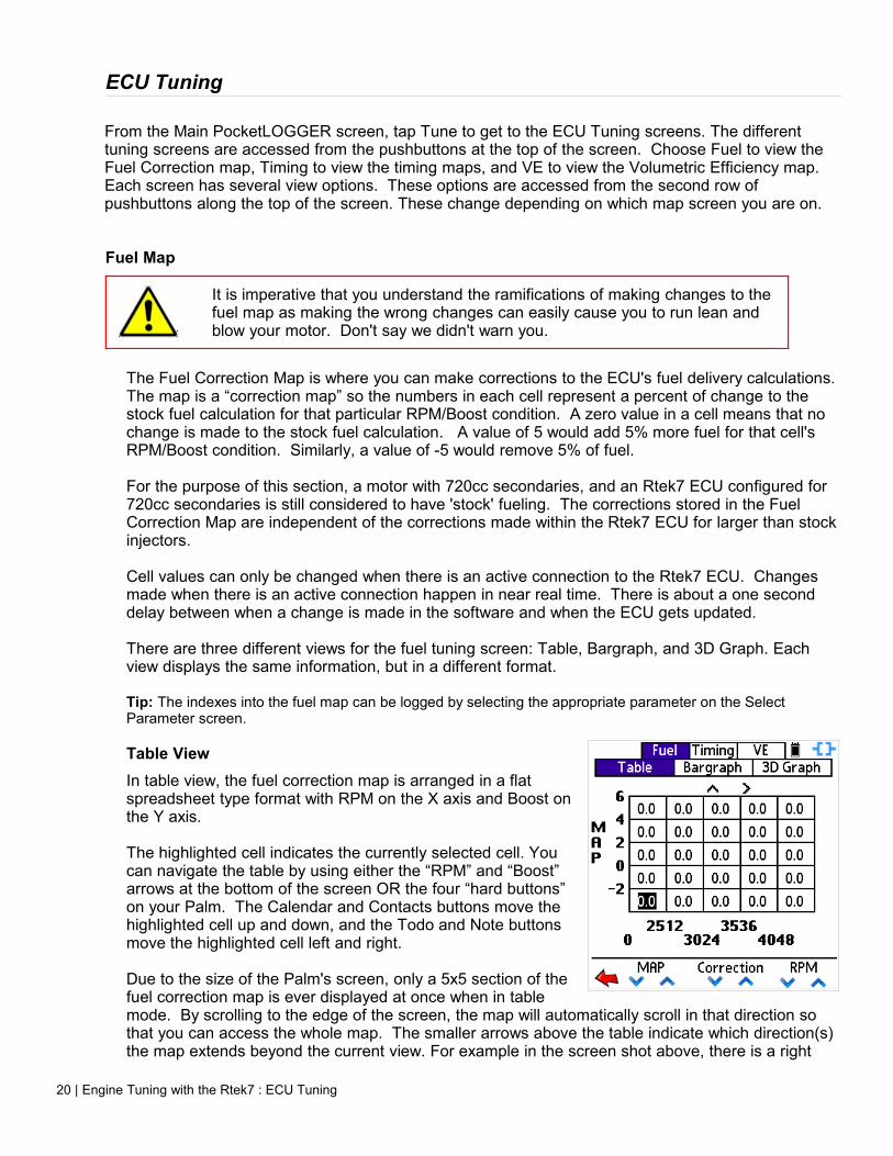
Table ViewIn table view, the fuel correction map is arranged in a flat spreadsheet type format with RPM on the X axis and Boost on the Y axis.
The highlighted cell indicates the currently selected cell. You can navigate the table by using either the “RPM” and “Boost” arrows at the bottom of the screen OR the four “hard buttons” on your Palm. The Calendar and Contacts buttons move the highlighted cell up and down, and the Todo and Note buttons move the highlighted cell left and right.
Due to the size of the Palm's screen, only a 5x5 section of the fuel correction map is ever displayed at once when in table mode. By scrolling to the edge of the screen, the map will automatically scroll in that direction so that you can access the whole map. The smaller arrows above the table indicate which direction(s) the map extends beyond the current view. For example in the screen shot above, there is a right
20 | Engine Tuning with the Rtek7 : ECU Tuning

and an up arrow displayed above the table. This means that you can scroll in those directions to display portions of the map that are not currently displayed.
To make a change to a cell's value, simply tap the up or down arrow under “Correction” at the bottom of the screen, OR use the hard Page up/down buttons on the bottom of your Palm, or on Palm's so equipped, use the up/down on the 5-way navigator.
Bargraph ViewBy tapping the “Bargraph” pushbutton at the top of the screen, the view switches to a bargraph type display. The bargraph interface is much like a graphic equalizer. Each 'slider' represents a cell for the current boost level (row) of the Fuel Correction map. The range of the adjustment varies depending on the ECU type and version.
As you know from the Table view, each row in the Fuel Correction map represents a boost level. On the Bargraph screen, the current row (boost level) that is being displayed is shown in the bottom left of the screen. In the screenshot on the right, you can see “-4” at the bottom left. This means the RPM columns from the -4 PSI row of the table are currently being displayed.
The hollow slider handle is the currently selected cell. In this screenshot, the third column (3024-3536 RPM) is selected on the -4 PSI row and it has a correction of +3.7%.
You can navigate by using the on-screen arrows or hard buttons just like when in the Table view. If the Fuel Correction Map has more than 10 columns, just like the table view, the bars will scroll if you navigate to the edge of the screen. You can make a change to a cell using the center set of on-screen up/down arrows under the correction, the hard Up/Down buttons, or by simply dragging the slider handle with the stylus. Once a slider handle is “grabbed” (stylus is down on it and you can drag it) the correction value for the slider's position is displayed above the center set of up/down arrows as you drag it around, but the ECU is NOT updated until the slider handle is let go.
3D Graph ViewBy tapping the “3D Graph” pushbutton at the top of the screen, the view switches to a 3D graph. This view allows you to view the whole map on one screen, which can be used to easily check for adjacent cells that have drastically different values.
Just like the Table view, you can navigate the map using the arrows at the bottom of the screen, or using the hard buttons at the bottom of your Palm. The current cell is highlighted with a dot on the graph. In the screenshot to the right, you can see the dot just right and above center. Referring to the bottom of the screen, you can see we are at the 8 PSI row and the 5584 RPM column.
To change the cell's value, use the center set of on-screen up/down arrows under the correction value (6.0% in the screenshot) or use the hard Page Up/Page Down buttons (or up/down on the 5-way) on the bottom of your Palm.
Engine Tuning with the Rtek7 : ECU Tuning | 21
Timing MapThe RX7 has two spark plugs per rotor. These are designated as leading (L) and trailing (T). When looking at the engine, the leading is the lower plug and the trailing is the top plug. Leading always fires first in an ignition cycle with the trailing following except under low load, high vacuum operation of the engine.
The following two paragraphs pertain to the N332 ECU only:
Internally, the N332 ECU actually uses a total of four timing maps, two for leading and two for trailing. Leading and trailing each have a 'low' map that covers 1024 to 4096 rpm, and a 'high' map that covers 4096 to 7168 rpm. The Rtek7 allows full adjustment of each map.
For simplicity, within the PocketLOGGER program, the low and the high maps are joined 'behind the scenes' so that one large map for leading, and one large map for trailing is presented to the user. Each map has 380 points and is arranged as Load (0-100%) vs RPM (1024 – 7168 RPM). Since the low and high maps are joined together, there are two "4096" rpm entries. In general these should be set to the same value.
Unlike the N332 ECU described above, the N326 and N351 ECUs use only a total of two timing maps, one for leading, one for trailing. The size of the timing maps vary depending on the ECU.
Cell values are degrees as would be measured on the eccentric shaft.
What values to set timing to is the subject of much debate and there are many good resources on the web for information on timing.
If you are not sure of the ramifications of changing timing values, it is strongly suggested that you do not alter the stock values. Improper timing values can lead to detonation which will destroy apex seals.
LoadEvery EFI system has a primary "load" sensor which is used as the basis for fuel and timing computations. MAP (Manifold Absolute Pressure) based EFI systems, such as the systems used in most Hondas, use hard coded VE (Volumetric Efficiency) data. Using RPM and MAP readings, the theoretical airflow is calculated based on pre-programmed data about the stock engine configuration. Since the ECU has no way of directly measuring actual airflow, no change is made to the fuel delivery if there is a change in the VE of the engine (how efficient the motor breathes; adding exhaust or intake, etc.)
The 2nd gen RX7 uses an AFM (Air Flow Meter) for this. This has the benefit of being "self adjusting" for many mods as the airflow is measured independently of the VE of the engine. Making changes to the VE of the motor (Adding exhaust, etc) increases airflow. This increase in airflow is measured by the AFM and the ECU adjusts fueling accordingly.
The Timing maps are arranged in an RPM vs Load table. A load point on the map will always relate to a certain airflow.
Tip: The indexes into the timing map can be logged by selecting the appropriate parameter on the Select Parameter screen.
Accessing Timing ScreensTapping the “Timing” pushbutton at the top of the screen will bring you to the Timing screens. Much
22 | Engine Tuning with the Rtek7 : ECU Tuning

like the Fuel Map screens, there is a “Table” and “Map” pushbutton that will switch how the timing maps are displayed. There is no Bargraph view for the timing tables. You will, however, see additional pushbuttons labeled “Leading”, “Trailing” and “Split”. Use these buttons to switch which timing map you would like to view.
Split MapSplit is the mathematical difference between the value at any given point on the leading map and the value at the same point on the trailing map, expressed in degrees. The Split map is a virtual map that exists only in the software. Values are calculated in real-time using the values of the Leading and Trailing maps. There is no actual Split map in the ECU.
Adjusting the split value results in changes to the trailing timing. For example if the Leading timing was 14.4 degrees and the trailing timing for that same cell was 14.2, Split would be 0.2. If you were to change the split to 0.4, the trailing map would be changed to 14.0.
Tapping the “Split” pushbutton at the top of the screen will display the Split map. You can view the Split Map using either the Table View or the “Map” view just like the leading and trailing maps.
Table ViewThe timing table view is nearly identical to the fuel table view, only the two axis are RPM and Load. Navigation is the same as the fuel table. Use the arrows at the bottom of the screen or the hard buttons at the bottom of the Palm. Make changes to a cell's value by using the center set of up/down arrows or the page up/down hard buttons at the bottom of the Palm.
Map ViewThe “Map” view pushbutton will change the display to a 3d graph view of whatever map you are currently viewing (Leading, Trailing, or Split). Navigating the Map view is the same as the 3D Graph Fuel Map view.
Engine Tuning with the Rtek7 : ECU Tuning | 23

Loading and Saving ECU ConfigurationsPocketLOGGER has the ability to load and save complete ECU setups. An “ECU Configuration” includes the fuel map, both timing maps, the ECU's injector configuration, as well as all other parameters configured on the ECU Setup screen.
Saving an ECU ConfigurationFrom any tuning screen, tap the menu silkscreen button and tap 'Save'. The Save Current Configuration screen will be displayed. Name your configuration by tapping the dotted line so that you see a cursor. Then enter a unique name for the current configuration. Tap Save when you are done naming your configuration, or Cancel, of you do not wish to save the configuration.
When you save a configuration, all data is saved.
Loading an ECU ConfigurationFrom any tuning screen, tap the menu silkscreen button and tap 'Load'. The Load Configuration screen will be displayed. In the top part of the screen, you will see a list of saved ECU configurations, if there are any.
Towards the bottom you will see four checkboxes. These checkboxes allow you select what part of the saved ECU Configuration you wish to load. This is useful if you only wish to restore one map, while not the others.
Along the bottom there are four icons.
Go back to the tuning screens
Rename the selected configuration
Delete the selected configuration
Load selected configuration into ECU
To delete, rename or load a configuration, first you have to highlight the name of the saved configuration you with to perform the action with. In the screen shot above, you can see the “Intake & exh 720p/s” configuration is highlighted. You can then tap the appropriate icon.
To load a configuration, highlight the configuration you want to load by tapping it, select what parts of the configuration you want to load using the checkboxes, then tap the Load icon. Loading times can vary and may take a while.
While an ECU update is in progress, do not turn off your Palm, close the application, disconnect the Palm from the car, turn the ignition off, or touch the Palm's screen. A partial configuration upload will result and can cause unpredictable results. If for some reason an ECU update did not complete, it is highly advisable that you retry until you successfully load an ECU Configuration before driving the car.
24 | Engine Tuning with the Rtek7 : Loading and Saving ECU Configurations
Chapter 5: DataloggingThe PocketLOGGER for RX7s has the ability to view and datalog (store) engine sensor data on the PDA. The amount of data stored is only limited by the available memory on your Palm.
Datalogging ScreensFrom the main screen, tap “Log” and you will be taken to the datalog screen. This is one of two datalog screens in which you can view and store real-time data.
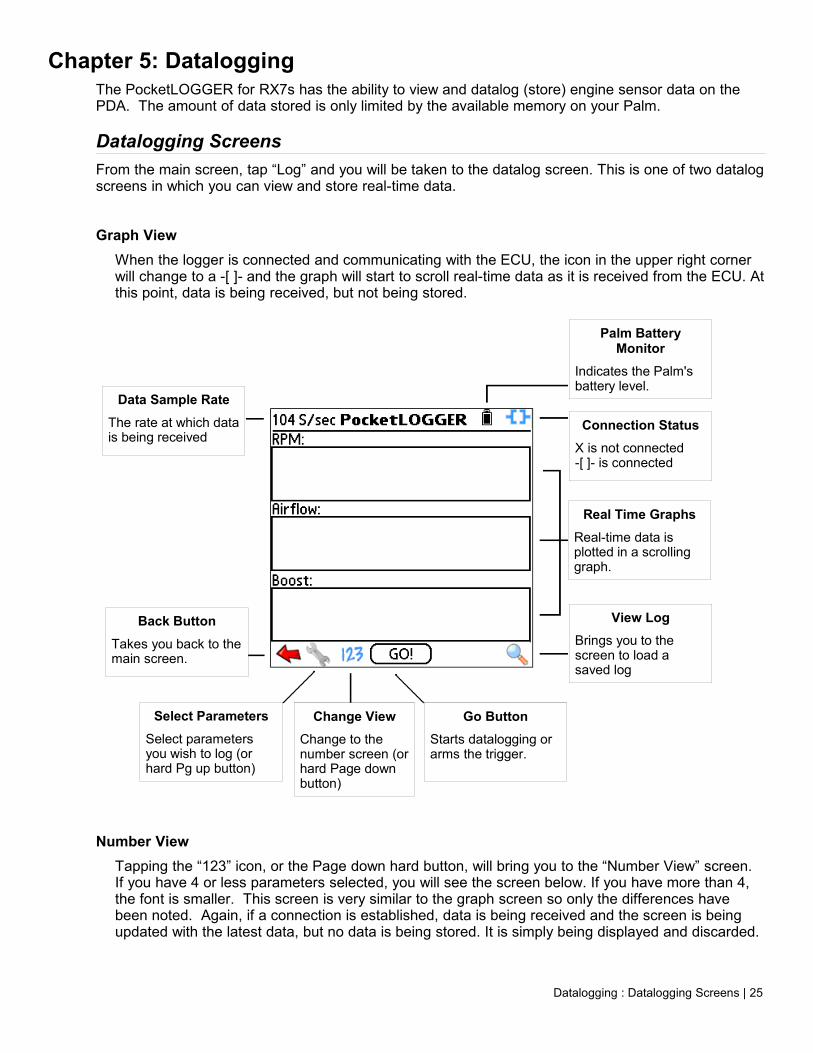
Graph ViewWhen the logger is connected and communicating with the ECU, the icon in the upper right corner will change to a -[ ]- and the graph will start to scroll real-time data as it is received from the ECU. At this point, data is being received, but not being stored.
Number ViewTapping the “123” icon, or the Page down hard button, will bring you to the “Number View” screen. If you have 4 or less parameters selected, you will see the screen below. If you have more than 4, the font is smaller. This screen is very similar to the graph screen so only the differences have been noted. Again, if a connection is established, data is being received and the screen is being updated with the latest data, but no data is being stored. It is simply being displayed and discarded.
Datalogging : Datalogging Screens | 25
Data Sample RateThe rate at which data is being received
Real Time GraphsReal-time data is plotted in a scrolling graph.
View LogBrings you to the screen to load a saved log
Go ButtonStarts datalogging or arms the trigger.
Back ButtonTakes you back to the main screen.
Select ParametersSelect parameters you wish to log (or hard Pg up button)
Change ViewChange to the number screen (or hard Page down button)
Palm Battery Monitor
Indicates the Palm's battery level.
Connection StatusX is not connected -[ ]- is connected

Select Parameters Screen
Tapping the wrench icon, or pressing the page up hard button, will bring you to the Select Parameters Screen. This is the screen that allows you to select the parameters that you want to view or datalog as well as set up the Alarm and Trigger conditions.
The parameters are loaded dynamically into the list depending on the ECU you are connected to. Additional loggable parameters can be viewed by tapping the small down arrow at the bottom right of the list box.
Select a parameter simply by tapping the checkbox next to it. When all the parameters that you'd like to log have been selected, tap the OK button, or press the page up hard button again.
Please note that supported parameters vary depending on ECU type and version.
ParametersRPM: Engine speedAirflow: Air volume as measured by the AFM sensorMAP: Manifold pressure as measured by the MAP sensorTPS (NB): Narrrow band throttle positionTPS (WB): Wideband throttle position (N351 Only)AFM Air Temp: Intake air temperature as measured in the AFM sensorIntake Air Temp: Intake air temperature as measure in the intake manifoldInjector P/W: 'Open' time of injectorPrimary Injector P/W: Open time of primary injectors (N351 Only)
26 | Datalogging : Select Parameters Screen
Real-time DataSensor data is displayed here
Min / MaxMin and max value for this parameter is displayed here
Change ViewChanges to graph view (or hard down button)
Display Min/MaxToggle between Min/Max data and realtime data display
Reset Min/MaxResets stored min/max data
Secondary Injector P/W: Open time of secondary injectors (N351 Only)Secondaries: When high, secondary injectors are currently being usedTiming Leading/Trailing: Ignition timing in degreesTiming Retard: Degrees the ECU is retarding the timing due to knockO2: Voltage output of the oxygen sensorCoolant temp: Temperature of the coolant in degreesBattery: Vehicle's battery voltage levelBarometer: Output of the ATP sensorATP Analog: Used to log external sensors when ECU is configured for “Use ATP Input as Analog”VR Analog: Used to log the external sensor connected to the VarRes input.
Table IndexesThe two table index parameters allow you to log the X and Y index into the respective map. This is useful to easily see where to make changes in a table. If the Fuel Table index is checked, you will see two additional parameters being logged, one for the RPM index and one for the boost index. These number relate directly to the rows and columns of the fuel table.
The Timing table index, when selected, will log either two or three parameters depending on the ECU: The load index of the timing table, and one or two RPM indexes. On the N332 ECU, the T-Indx RPM L relates to the 13 cells from 0 to 4096 RPM. Values will be 0 to 12. The T-Indx RPM H relates to the 7 cells above 4096. Values will be 0 to 6. All other ECUs only have one T-Index RPM parameter representing the full range of the timing table columns.
Quick SelectsPocketLOGGER has the ability to store 4 Quick Selects. If you log the same parameters all the time, this feature allows you to select them quickly and easily. To select the parameters associated with a Quick Select, simply tap the appropriate button 1 through 4.
Programming Quick SelectsTo program a Quick Select button, first select the parameters that you would like stored for that Quick Select. Next tap the Program button, then the Quick Select button you wish to program with the selected parameters. That button is now programmed with those parameters. Tapping the numbered
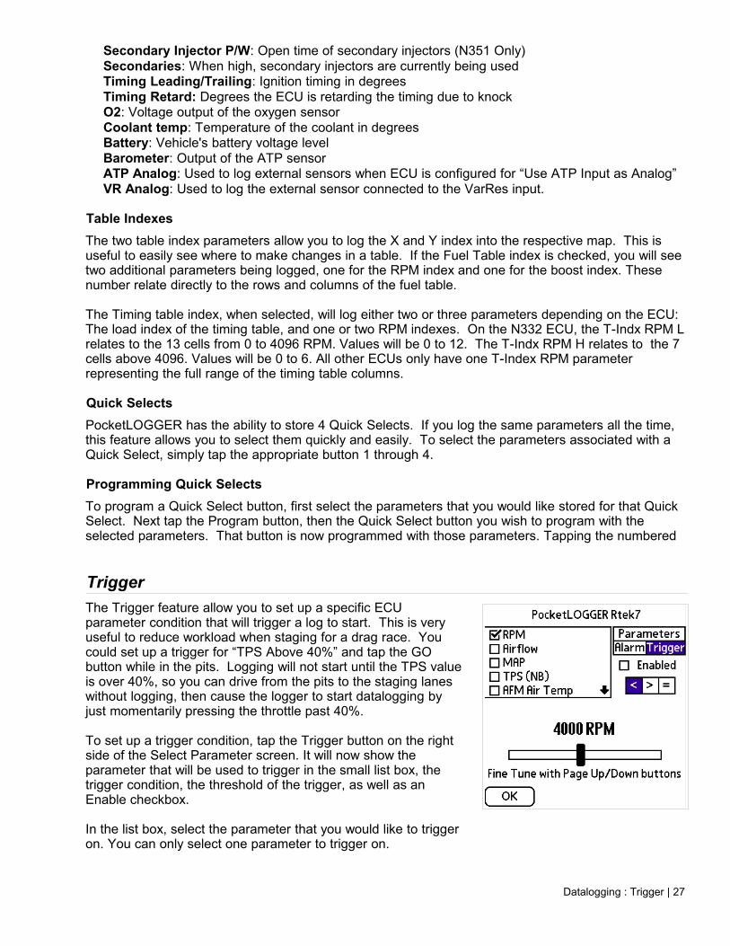
TriggerThe Trigger feature allow you to set up a specific ECU parameter condition that will trigger a log to start. This is very useful to reduce workload when staging for a drag race. You could set up a trigger for “TPS Above 40%” and tap the GO button while in the pits. Logging will not start until the TPS value is over 40%, so you can drive from the pits to the staging lanes without logging, then cause the logger to start datalogging by just momentarily pressing the throttle past 40%.
To set up a trigger condition, tap the Trigger button on the right side of the Select Parameter screen. It will now show the parameter that will be used to trigger in the small list box, the trigger condition, the threshold of the trigger, as well as an Enable checkbox.
In the list box, select the parameter that you would like to trigger on. You can only select one parameter to trigger on.
Datalogging : Trigger | 27
If you do not log the parameter you have selected as the trigger parameter, then the trigger will not work. i.e.: If you set up to trigger on RPM, then you need to make sure RPM is selected on the Parameters screen. If it is not, the trigger function will be disabled and a datalog will start immediately after the GO button is tapped.
To enable the trigger feature, check the Enable checkbox. If this checkbox is not checked, when you tap the “GO” button, a datalog will start regardless of whether the condition displayed is met. Regardless of whether the Enabled checkbox is checked, the condition that is set up is saved when you tap the OK button.
Next, select the appropriate conditional sign. If the < is selected the trigger will activate if the incoming value for the selected parameter is less than the value set on the slider. Conversely, selecting the > button will activate the trigger if the incoming value for the selected parameter is greater than the value set on the slider. You can toggle the = button on and off if you would like to trigger precisely at the slider value in addition to the > or < selection. i.e.: If you selected RPM as the parameter, 4000 as the slider value, and the > button, the trigger would activate only once the engine RPM is above 4000 RPM, but not at 4000 RPM. If the = button was selected as well, then the trigger would activate at 4000 or above.
Lastly, use the slider to set the threshold value. The slider can be used to get the threshold value near the desired value. You can use the hard Page Up/Down buttons (or up down on the 5-way) to fine tune the threshold value.
Logging Data
Data is captured from either log screens (Number or graph) by simply tapping the “GO” button while you have an active connection to the ECU. Keep in mind that the the ignition must be on in order for a connection to be established.
The “GO” button will turn to “STOP” (or “ARMED” if a trigger is set) and will begin flashing. If the button is flashing, data is being stored in memory. Pressing the STOP button will halt the storage of data. If data is logged for more than 5 seconds, the log is automatically named with the current date and time and saved. Datalogs that are less than 5 seconds are automatically discarded. If your Palm's date and time are not set correctly, the logs will not have correct timestamps which could become confusing when looking for a log later.
Using a Trigger to Start DataloggingWhen you have a trigger enabled, Tapping the GO button in either datalog screen will change the button to ARMED. “Armed” means the log is waiting for the trigger condition to be met before it starts the log. If the condition is already met when the GO button is pressed, the log will start right away.
If the button is tapped when it says ARMED the trigger will be disarmed and the button goes back to “GO”. No data is saved.
If the parameter that you select to trigger on is not selected in the “Select Parameters” screen for logging, the trigger will not work because the data is not currently being retrieved from the ECU.
28 | Datalogging : Using a Trigger to Start Datalogging
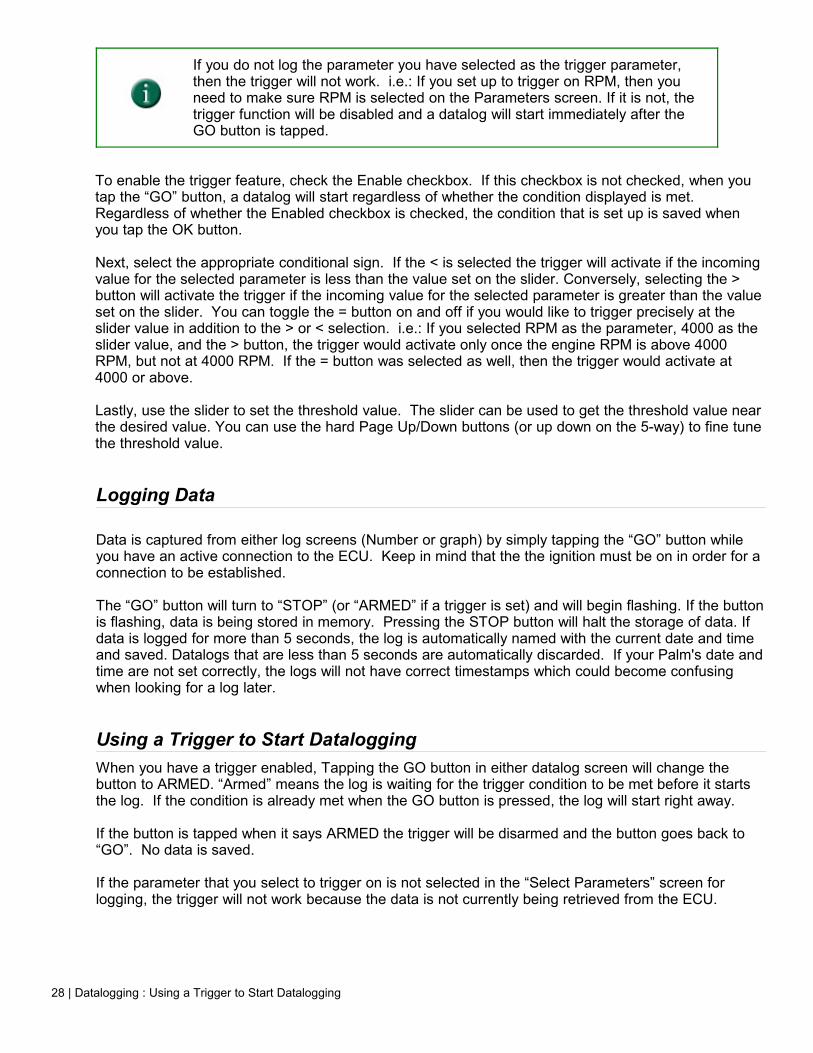
AlarmThe Alarm feature is very similar to the Trigger feature, only it makes the Palm beep when the condition is met.
Tap the Alarm button in the Select Parameters screen. You set up an alarm just like a trigger. Enable it by tapping the Enable checkbox, select a conditional sign(s), and use the slider to select the threshold value.
If, in the Select Parameters screen, you do not select the parameter you would like to trip the alarm, the alarm will not work.
If the Alarm's “Enable” checkbox is not checked, the alarm is not used, but the condition is saved if you ever want to re-enable it.
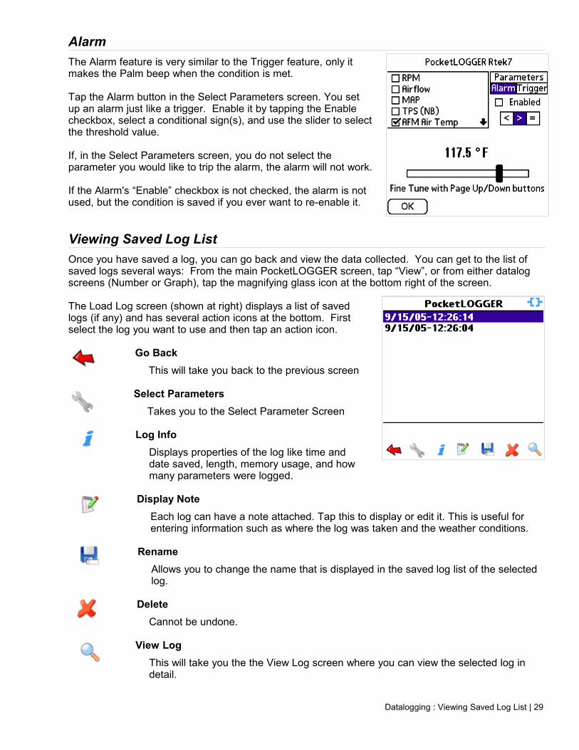
Viewing Saved Log ListOnce you have saved a log, you can go back and view the data collected. You can get to the list of saved logs several ways: From the main PocketLOGGER screen, tap “View”, or from either datalog screens (Number or Graph), tap the magnifying glass icon at the bottom right of the screen.
The Load Log screen (shown at right) displays a list of saved logs (if any) and has several action icons at the bottom. First select the log you want to use and then tap an action icon.
Go BackThis will take you back to the previous screen
Select ParametersTakes you to the Select Parameter Screen
Log InfoDisplays properties of the log like time and date saved, length, memory usage, and how many parameters were logged.
Display NoteEach log can have a note attached. Tap this to display or edit it. This is useful for entering information such as where the log was taken and the weather conditions.
RenameAllows you to change the name that is displayed in the saved log list of the selected log.
DeleteCannot be undone.
View LogThis will take you the the View Log screen where you can view the selected log in detail.
Datalogging : Viewing Saved Log List | 29
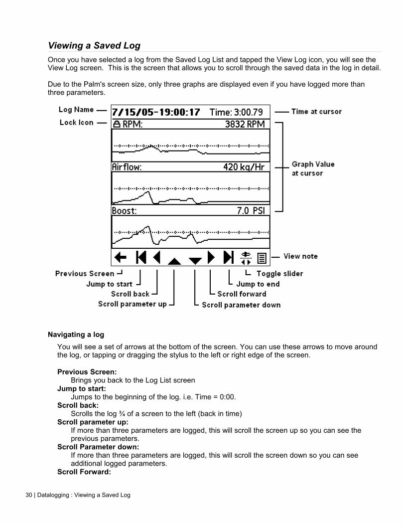
Viewing a Saved LogOnce you have selected a log from the Saved Log List and tapped the View Log icon, you will see the View Log screen. This is the screen that allows you to scroll through the saved data in the log in detail.
Due to the Palm's screen size, only three graphs are displayed even if you have logged more than three parameters.
Navigating a logYou will see a set of arrows at the bottom of the screen. You can use these arrows to move around the log, or tapping or dragging the stylus to the left or right edge of the screen.
Previous Screen: Brings you back to the Log List screen
Jump to start: Jumps to the beginning of the log. i.e. Time = 0:00.
Scroll back: Scrolls the log ¾ of a screen to the left (back in time)
Scroll parameter up: If more than three parameters are logged, this will scroll the screen up so you can see the previous parameters.
Scroll Parameter down: If more than three parameters are logged, this will scroll the screen down so you can see additional logged parameters.
Scroll Forward:
30 | Datalogging : Viewing a Saved Log
Scrolls the log ¾ of a screen to the right (forward in time)Jump to end:
Jumps to the end of the log.Toggle Slider:
This will remove the navigation arrows and replace it with a slider. Tap again to go back to the arrows.
View note: View the note associated with this log
Using the Navigation SliderBy tapping the Toggle Slider button, the Navigation Slider will appear in place of the Navigation Arrows. The slider is useful if you would like to make large jumps in a long log. Instead of scrolling ¾ of a screen at a time, you can just drag the slider to the appropriate time. When you drag the slider knob, the Time readout at the top will display the time position of the slider, but the graphs will not update. When you let go of the slider, the log will jump to the currently displayed time and the graphs will update with the proper data.
Zooming in and outThere are no icons for zooming. You use the Page up/down hard keys at the bottom of your Palm, or up/down on the 5-way navigator. Zooming allows you to stretch out the log horizontally (in time) so that you can see more detail.
Viewing Exact Parameter ValuesExact parameter values can be viewed at any time by simply tapping or sliding the stylus at any point in the graph. The actual value at the stylus will be displayed above and to the right of each graph.
Locking a GraphThere may come a time you want to compare three graphs that are not near each other. Since the Palm will only display three graphs at one time we have added a “Graph Lock” feature that allows you to lock up to two graphs on the screen. When a graph is locked on the screen, the Scroll Parameter Up/Down buttons have no effect on that graph.
To lock a graph, simply tap the name of the parameter. If it's not already at the top, the graph will move to the top (or second position if you already have another locked graph) and a lock icon will be displayed next to the parameter name.
To unlock a graph, tap the parameter name again.
Using the Graph Lock feature, you could lock two of the parameters you want to compare, and use the Scroll Parameter Up/Down buttons to change the third graph to the one you want to compare to the other two.
Datalogging : Viewing a Saved Log | 31

Datalogging PreferencesFrom the main screen, or either Datalog screens, if you tap the menu silkscreen button, you will see a Preferences menu item. This will bring you to the Preferences screen. Preferences are saved between program executions.
Tap anywhere to start logWhen this option is checked, you can tap almost anywhere on the screen while on either Datalog screens (Number or Graph view) to start or stop the log, instead of having to tap the small “GO” button. This makes it much easier to start/stop a log, but also increases the chance that a log will start inadvertently.
5 Second beep while loggingWhen checked the Palm will emit a beep every five seconds to remind you that you are collecting data. When you are collecting data, the Palm's memory is slowly being filled. Technically you could completely fill the Palm's memory if a log was inadvertently started without your knowledge. The reminder beep would keep this from happening.
Metric and Imperial PushbuttonsTap either Metric or Imperial to change the units used to display certain engine parameters (all temperatures, the MAP sensor, airflow, and altitude).
Setup Ext. SensorTap this button to configure the scaling of the external sensor. See the External Sensors and Devices chapter for more information.
32 | Datalogging : Datalogging Preferences
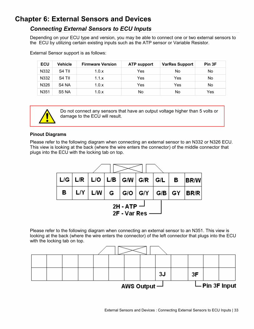
Chapter 6: External Sensors and DevicesConnecting External Sensors to ECU InputsDepending on your ECU type and version, you may be able to connect one or two external sensors to the ECU by utilizing certain existing inputs such as the ATP sensor or Variable Resistor.
External Sensor support is as follows:
ECU Vehicle Firmware Version ATP support VarRes Support Pin 3FN332 S4 TII 1.0.x Yes No NoN332 S4 TII 1.1.x Yes Yes NoN326 S4 NA 1.0.x Yes Yes NoN351 S5 NA 1.0.x No No Yes
Do not connect any sensors that have an output voltage higher than 5 volts or damage to the ECU will result.
Pinout DiagramsPlease refer to the following diagram when connecting an external sensor to an N332 or N326 ECU. This view is looking at the back (where the wire enters the connector) of the middle connector that plugs into the ECU with the locking tab on top.
Please refer to the following diagram when connecting an external sensor to an N351. This view is looking at the back (where the wire enters the connector) of the left connector that plugs into the ECU with the locking tab on top.
External Sensors and Devices : Connecting External Sensors to ECU Inputs | 33

Using the Variable Resistor Input
Please refer to the chart above to make sure your ECU supports using the Variable Resistor input as an external input before proceeding.
On vehicles that support using the Variable Resistor as an external input, there is no need to enable it as an input as ECU is permanently configured to use the VarRes input as an external analog input. The Rtek moves the function of the the Variable Resistor under the hood into the software so there is no need for it anymore. This frees up the VarRes input to use as an external analog input. For more information on using the Var Res to set up Idle Fueling, please see the ECU Setup section in chapter 4.
It is recommended that if your ECU supports using the ATP and Var Res input, you utilize the Var Res input before using the ATP input.
In order to connect the external sensor to the ECU, you must first disconnect the Variable Resistor from the ECU. The VarRes wire is located in position 2F of the ECU's harness. Please refer to the diagram above to locate the proper wire. This wire will need to be cut. Make sure you leave enough wire coming out of the ECU to connect your sensor to!!
Connect the 0-5 volt output of your external sensor to the end of the wire exiting the ECU connector from position 2F. Make sure your connection is good (soldering is recommended, “vampire” taps are definitely not) as a marginal connection will affect your readings. It is also a good idea to connect the sensor's ground wire to the ECU's ground wire as well. This will help eliminate discrepancies in the readings. Tape up the connection as well as the other (unconnected) end of the original VarRes wire. Don't forget to configure the external sensor scaling as described in the Configuring External Sensor Scaling section of this chapter.
Using the ATP Sensor Input
You must put the ECU in “Use ATP for analog input” mode before connecting any external sensors to it. Failure to do so can lead to catastrophic engine damage due to a lean condition! See the ECU Setup section in chapter 4.
The ECU MUST be configured to let it know not to use the ATP input for it's barometric pressure calculations so BEFORE connecting any external input, make sure the “Use ATP as Analog input” is checked on the ECU Setup screen (Chapter 3) and the appropriate altitude is selected.
In order to connect the external sensor to the ECU, you must first disconnect the ATP sensor. The ATP sensor wire is located in position 2H of the ECU's harness. Please refer to the diagram above to locate the proper wire. This wire will need to be cut. Make sure you leave enough wire coming out of the ECU to connect your sensor to!!
Connect the 0-5 volt output of your external sensor to the end of the wire exiting the ECU connector from position 2H. Make sure your connection is good (soldering is recommended, “vampire” taps are definitely not) as a marginal connection will affect your readings. It is also a good idea to connect the sensor's ground wire to the ECU's ground wire as well. This will help eliminate discrepancies in the readings. Tape up the connection as well as the other (unconnected) end of the original ATP wire. Don't forget to configure the external sensor scaling as described in the Configuring External Sensor Scaling section of this chapter.
34 | External Sensors and Devices : Connecting External Sensors to ECU Inputs

Using Pin 3F as InputOne S5NA cars, pin 3F is unused from the factory. The Stage 2 Rtek7 ECU converts this into a full time general use loggable input. There is no need to enable this input, it is always configured as a general use input. Configure the external sensor scaling as described in the Configuring External Sensor Scaling section of this chapter.
Configuring External Sensor ScalingAlong with the ECU's ability to read an external 0-5V sensor, you can configure PocketLOGGER to scale the voltage any way you'd like. This allows you to change the value that PocketLOGGER displays in the View and Datalog screens so that the displayed value is easy to understand.
For example, a common use of the external analog input is to log a wideband A/F meter. Normally the wideband puts out a voltage between 0 and 5 volts, but displaying a voltage on the PocketLOGGER screen would not be very useful as you would need to convert the voltage to an A/F ratio in your head. Using the External Sensor Setup screen, you could instead set up PocketLOGGER to convert the 0-5 volts to display actual A/F ratio which would be much more easily read and understood.
Please note that the scaling routines built into PocketLOGGER can only be used with sensors that have linear transfer functions.
The math function that is applied to the input voltage can be expressed as:
(Input Voltage * Multiplier) + Offset = Displayed Value
Accessing the External Sensor Scaling ScreenFrom the Main Screen, tap the menu silkscreen button, tap the “Preferences” menu item, then “Ext Sensor Setup button. You will see the screen shown below. At the top of the screen, use the pushbuttons to select the input you wish to set up. ATP will display the scaling used when logging the Atmospheric Pressure Sensor as an analog input and Var Res will display the scaling used when logging the Variable Resistor input as an analog input. On S5 cars, the “ATP” label on the pushbutton will be replaced with “Pin 3F”.
When you tap OK, the multiplier and offset values are stored in the program preferences and will reloaded every time you run the program, until you change them. The values in the calculator area are not stored
Cancel will restore the multiplier and offset values to what they were when you entered the screen.
Please note that not all ECUs support external inputs and the ability to set up scaling within the PocketLOGGER software has no bearing on whether your particular ECU type/version supports using the ATP or VarRes as External Sensor inputs. The information entered on this screen is saved on the Palm and not in the ECU.
Configuring Sensor ScalingThere are three ways to set up the external sensor scaling: Selecting a preset from the list, entering the multiplier and offset directly, or using the built in calculator to calculate the multiplier and offset.
External Sensors and Devices : Configuring External Sensor Scaling | 35

PresetsTap the Presets pulldown to select from a list of common sensors. These are built right into PocketLOGGER so there is no need to search for or calculate the multiplier and offset yourself. If you are using one of the listed sensors, simply tap it to select it. The proper multiplier and offset values are updated accordingly. You are done setting up the sensor, tap OK.
MultiplierThis is the multiplier value used in the expression above. To change it, tap the number to display the cursor. Then input the new number.
OffsetThis is the offset value used in the expression above. To change it, tap the number to display the cursor. Then input the new number.
+/-Tap the +/- icon to toggle the sign of the value next to it.
CalculatorThe calculator is supplied for those users that may not have the transfer function of their sensor's output, but have a voltage vs. value chart or list of voltages and the associated values for those voltages.
To use the calculator, enter two points from the list or chart. These two points should be far apart from each other. Typically the two points will be 0 volts and 5 volts. You would enter 0 in the Ref1 volts field, and enter 5 on the Ref2 volts field. Then you would enter the associated values for 0 and 5v in the Value column. Once you are done entering the values, click Calc. The transfer function is calculated and the multiplier and offset values are inserted into the appropriate fields. Tap OK.
Tweaking the Display ValuesDue to variations in hardware, wiring, supply voltage, and grounds, you may find that the displayed value for the external sensor does not match the actual sensor reading. This can be evident if you have, for example, a wideband A/F Meter with a built in display. The built in display and the PocketLOGGER display may not match exactly.
In order to get the two displayed values closer together, you can adjust the offset value slightly by the amount of the discrepancy, in the opposite direction.
For example, if you see the built in display is showing 13.00 and the PocketLOGGER is displaying 13.02, the PocketLOGGER is 0.02 too high. To fix this, take 0.02 away from the offset value displayed on the External Sensor Setup screen. If the offset value was 10, change it to 9.98. This would put the two displayed values closer together.
Due to refresh rates and hardware limitations, the two displays will typically never read exactly the same all of the time, but they will be very close most of the time.
36 | External Sensors and Devices : Configuring External Sensor Scaling

Controlling External Devices with the ECUCertain ECUs have the ability to utilize an output as an RPM controlled output. This could be used to control anything from a shift light to a nitrous system. Please see the chart in the beginning of Chapter 3 for information on whether your ECU supports this feature.
Pinout DiagramsPlease refer to the following diagram when connecting an external sensor to an ECU. This view is looking at the back (where the wire enters the connector) of the middle connector that plugs into the ECU with the locking tab on top.
EGR Output for S4 Cars
AWS Output for S5 Cars
Electrical Characteristics of the ECU OutputThe ECU outputs are open-collector, active low outputs. This means that when the output is not activated, the output wire is not connected to anything. When the output is active, the output wire is grounded.
While the diagram above depicts a switch in the ECU for simplicity, the actual switching circuit utilizes solid state components. These components have a much lower current limit than a switch or relay. If you must control a device that can draw more than 500ma of current, you must use a relay
External Sensors and Devices : Controlling External Devices with the ECU | 37
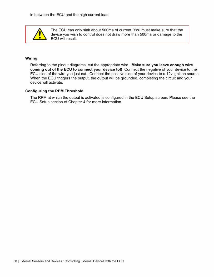
in between the ECU and the high current load.
The ECU can only sink about 500ma of current. You must make sure that the device you wish to control does not draw more than 500ma or damage to the ECU will result.
WiringReferring to the pinout diagrams, cut the appropriate wire. Make sure you leave enough wire coming out of the ECU to connect your device to!! Connect the negative of your device to the ECU side of the wire you just cut. Connect the positive side of your device to a 12v ignition source. When the ECU triggers the output, the output will be grounded, completing the circuit and your device will activate.
Configuring the RPM ThresholdThe RPM at which the output is activated is configured in the ECU Setup screen. Please see the ECU Setup section of Chapter 4 for more information.
38 | External Sensors and Devices : Controlling External Devices with the ECU

Chapter 7: DiagnosticsDiagnostic ScreensFrom the main screen, tap “Diag” to enter the diagnostic mode. The diagnostic mode consist of two screens, Error Codes and ECU Digital I/O status.
Reading Error CodesBy tapping the small “CE” icon at the bottom of the screen, you will see the Error Codes screen. This screen displays the current errors the ECU is sensing. The RX7 ECU does not store error codes, the list is updated in realtime. To clear an error, you must fix the problem that is causing the error.
Digital Input and Output StatusBy tapping the I/O icon (the one with two arrows) brings you to the I/O status screen. This will tell you the status of the inputs and outputs of the ECU. You can switch between Inputs and Outputs but tapping the appropriate push button towards the bottom of the screen. Both screens are read only, so you can only read the status, you can't change them.
When a box is checked, that I/O is active. For instance, in the screen to the right, there is a check mark next to the Water Temp Switch. This means that the the switch that is connected to the Water Temp Switch input is active.
On the output screen if an output is checked, that means the ECU has activated that output. Keep in mind that an “active” output can mean that the ECU has grounded that output. It does not necessarily mean you will find +12v on that wire.
Diagnostics : Diagnostic Screens | 39

Appendix I: PocketLOGGER Software Screen Tree
40 | Diagnostics : Diagnostic Screens
Appendix II: END-USER LICENSE AGREEMENT FOR POCKETLOGGER™ for Rtek7
This End-User License Agreement ("EULA") is a legal agreement between you (either an individual or a single entity) and the mentioned author of this Software for the software product identified above, which includes computer software, related files and their formats, and may include associated media, printed materials, and "online" or electronic documentation ("SOFTWARE PRODUCT"). By installing, copying, or otherwise using the SOFTWARE PRODUCT, you agree to be bound by the terms of this EULA. If you do not agree to the terms of this EULA, do not install or use the SOFTWARE PRODUCT; you may, however, return it to your place of purchase for a full refund.
SOFTWARE PRODUCT LICENSE
The SOFTWARE PRODUCT is protected by copyright laws and international copyright treaties, as well as other intellectual property laws and treaties. The SOFTWARE PRODUCT is licensed, not sold.
1. GRANT OF LICENSE.
This EULA grants you the following rights: Installation and Use. You may install and use one copy of the SOFTWARE PRODUCT on a single Palm device. You may NOT use the SOFTWARE PRODUCT on more than one Palm device at any time.
Reproduction and Distribution. You may not reproduce or distribute copies of the SOFTWARE PRODUCT.
Registration keys are NOT to be distributed.
2. DESCRIPTION OF OTHER RIGHTS AND LIMITATIONS.
Limitations on Reverse Engineering, Decompilation, and Disassembly. You may not reverse engineer, decompile, or disassemble the SOFTWARE PRODUCT, any of the SOFTWARE PRODUCT's related files, or any file created with the SOFTWARE PRODUCT, except and only to the extent that such activity is expressly permitted by applicable law notwithstanding this limitation.
Separation of Components. The SOFTWARE PRODUCT is licensed as a single product. Its component parts may not be separated for use on more than one computer.
Software Transfer. You may permanently transfer all of your rights under this EULA, provided the recipient agrees to the terms of this EULA, the original owner deletes all components of the SOFTWARE PRODUCT, and a $25 transfer fee is paid to digital tuning, inc.
Termination. Without prejudice to any other rights, the Author of this Software may terminate this EULA if you fail to comply with the terms and conditions of this EULA. In such event, you must destroy all copies of the SOFTWARE PRODUCT and all of its component parts.
Distribution. The SOFTWARE PRODUCT may not be sold or be included in a product or package which intends to receive benefits through the inclusion of the SOFTWARE PRODUCT. Files (captured data) created with the SOFTWARE PRODUCT can be freely distributed. These files are still protected under this End User License Agreement and anyone that receives and uses these files are bound to this agreement.
3. COPYRIGHT.
All title and copyrights in and to the SOFTWARE PRODUCT (including but not limited to any images, photographs, animations, video, audio, music, text, and "applets" incorporated into the SOFTWARE PRODUCT), the accompanying printed materials, and any copies of the SOFTWARE PRODUCT are owned by the Author of this Software. The SOFTWARE PRODUCT is protected by copyright laws and international treaty provisions. Therefore, you must treat the SOFTWARE PRODUCT like any other copyrighted material except that you may install the SOFTWARE PRODUCT on a single computer provided you keep the original solely for backup or archival purposes.
4. MISCELLANEOUS
Should you have any questions concerning this EULA, or if you desire to contact the author of this Software for any reason, please contact [email protected]
5. LIMITED WARRANTY
NO WARRANTIES. The Author of this Software expressly disclaims any warranty for the SOFTWARE PRODUCT. The SOFTWARE PRODUCT and any related documentation is provided "as is" without warranty of any kind, either express or implied, including, without limitation, the implied warranties or merchantability, fitness for a particular purpose, or noninfringement. The entire risk arising out of use or performance of the SOFTWARE PRODUCT remains with you.
NO LIABILITY FOR DAMAGES. In no event shall the author of this Software be liable for any damages whatsoever (including, without limitation, damages for loss of business profits, business interruption, loss of business information, or any other pecuniary loss) arising out of the use of or inability to use this product, even if the Author of this Software has been advised of the possibility of such damages. Because some states/jurisdictions do not allow the exclusion or limitation of liability for consequential or incidental damages, the above limitation may not apply to you.
Diagnostics : Diagnostic Screens | 41