pol tank farm – layers of protection -...
TRANSCRIPT
K S Unni,DGM - Special Projects, O&D
16.01.14 HPCL
POL Tank Farm – Layers ofProtection
Plan of Presentation
Rim Seal Protection System2
HC Monitoring System3
Tank Appurtenances & Overfill ProtectionSystem
1

Introduction
• Tank farms/storage area need effective safetysolutions to protect Personnel, Asset andEnvironment
• Tank farms present difficult challenges for Safetytechnology
• Being a hazardous area, requires continuousmonitoring
• Tank farm should have accurate, reliablemonitoring system

POL locations: Safety Systems
HVLRMonitors
Tank FarmMgmt.
System
ROSOV
HydroCarbon
Detectors
Rim SealFire
Protection
Rated equipment along with Dedicated Safety PLC
Plan of Presentation
Rim Seal Protection System2
HC Monitoring System3
Tank Appurtenances & Overfill ProtectionSystem
1
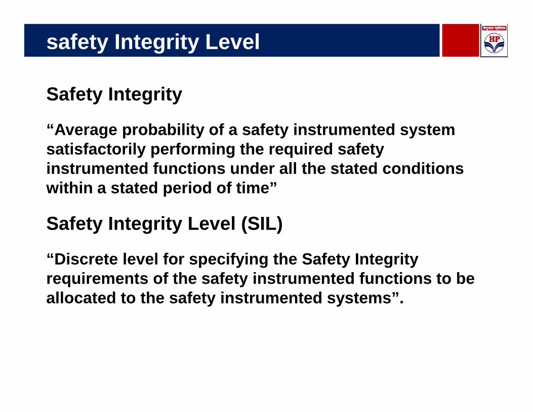
safety Integrity Level
Safety Integrity
“Average probability of a safety instrumented systemsatisfactorily performing the required safetyinstrumented functions under all the stated conditionswithin a stated period of time”
Safety Integrity Level (SIL)
“Discrete level for specifying the Safety Integrityrequirements of the safety instrumented functions to beallocated to the safety instrumented systems”.
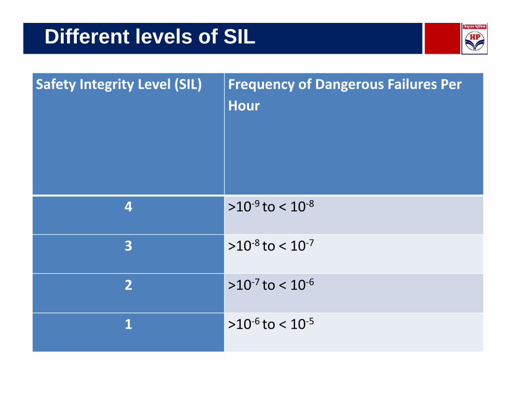
Different levels of SIL
Safety Integrity Level (SIL) Frequency of Dangerous Failures PerHour
4 >10-9 to < 10-8
3 >10-8 to < 10-7
2 >10-7 to < 10-6
1 >10-6 to < 10-5

SIL-2 Compliant Equipment
Leveragingtechnology
Level Switch(Vibrating Fork)
Safety PLC
Radar Gauge andRelay Output

Major Appurtenances
ROSOV is the body valve of the tankwhich is Fail Safe and can beoperated Remote or local
Radar Gauges of SIL 2 certified

Safety Interlock loop for Over fill Protection
PrimaryRadar, WLS
& Temp.
GrossLevelWaterLevel
Density
Temper.
SecondaryRadar Gauge
H Level
HH Level
HHH Level
Level Switch
HHH Level
ESD PLC featuresRadar Gauge + Level Switch
• Safety PLC – SIL 2 orbetter certified
• Radar Gauge, LevelSwitch , Relay Output –min SIL 2 Certified
• All Radar Gauges shall bewith +/- 1 mm accuracy
• HHH alarm activationbasis feed back eitherfrom SIL Radar Gauge orLevel Switch which ever isearlier.
TAS PLC
ESDPLC
Standardized Levels
HHH(PESO)
HHH
0.65 mtrs
0.25 mtrs
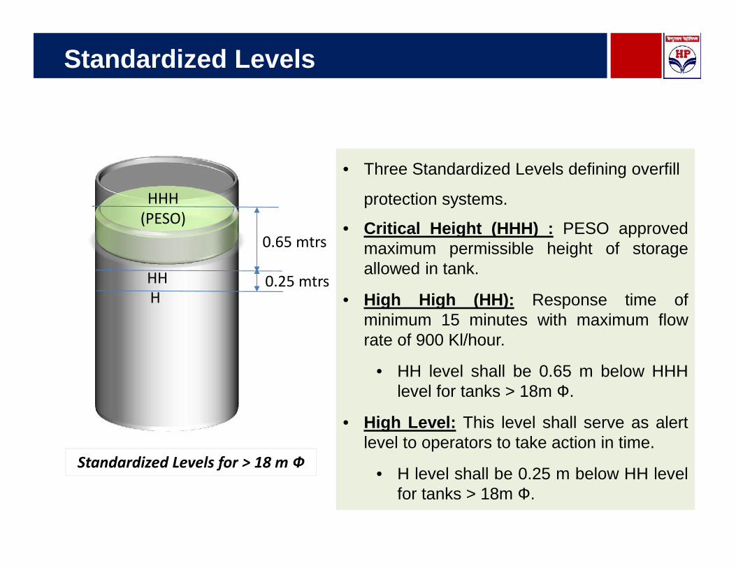
Standardized Levels for > 18 m Ф
• Three Standardized Levels defining overfill
protection systems.
• Critical Height (HHH) : PESO approvedmaximum permissible height of storageallowed in tank.
• High High (HH): Response time ofminimum 15 minutes with maximum flowrate of 900 Kl/hour.
• HH level shall be 0.65 m below HHHlevel for tanks > 18m Ф.
• High Level: This level shall serve as alertlevel to operators to take action in time.
• H level shall be 0.25 m below HH levelfor tanks > 18m Ф.
Standardized Levels
HHH(PESO)
HHH
1.3 mtrs
0.5 mtrs
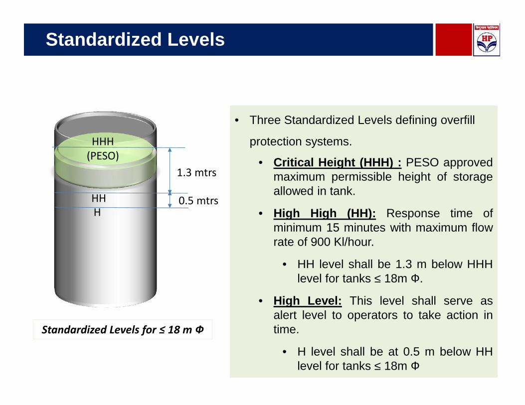
Standardized Levels for ≤ 18 m Ф
• Three Standardized Levels defining overfill
protection systems.
• Critical Height (HHH) : PESO approvedmaximum permissible height of storageallowed in tank.
• High High (HH): Response time ofminimum 15 minutes with maximum flowrate of 900 Kl/hour.
• HH level shall be 1.3 m below HHHlevel for tanks ≤ 18m Ф.
• High Level: This level shall serve asalert level to operators to take action intime.
• H level shall be at 0.5 m below HHlevel for tanks ≤ 18m Ф

Communication Structure
Signal fromfield equipment Safety PLC TAS PLC DR Centre

Additional Features in Tank Farm Protection
Integration of Pipe Line PLC and TAS PLC for Product receipt, despatch andalarms
Automation of Under ground tanks should be part of Tank FarmManagement System by providing Radar Gauge etc.
Tank Body Valve (ROSOV) should be designated as Safety Valve & thesecond valve (MOV) is designated as Process (Operating) Valve
ROSOV shall be closed on ESD activation, Hi-Hi-Hi level activation orLocal push button located outside Dyke wall or from the Control Room
ROSOV should be opened only through push button available outsidethe dyke or Control Room. ROSOV for idle tanks should be kept closed.
All data related to Valves operations in Auto-Remote/Auto-Manual Mode/Local Mode shall be logged with time & date Stamp.
Dyke Valve position indicator should be provided in the System. In case of openDyke Valve status alert shall come to the control room
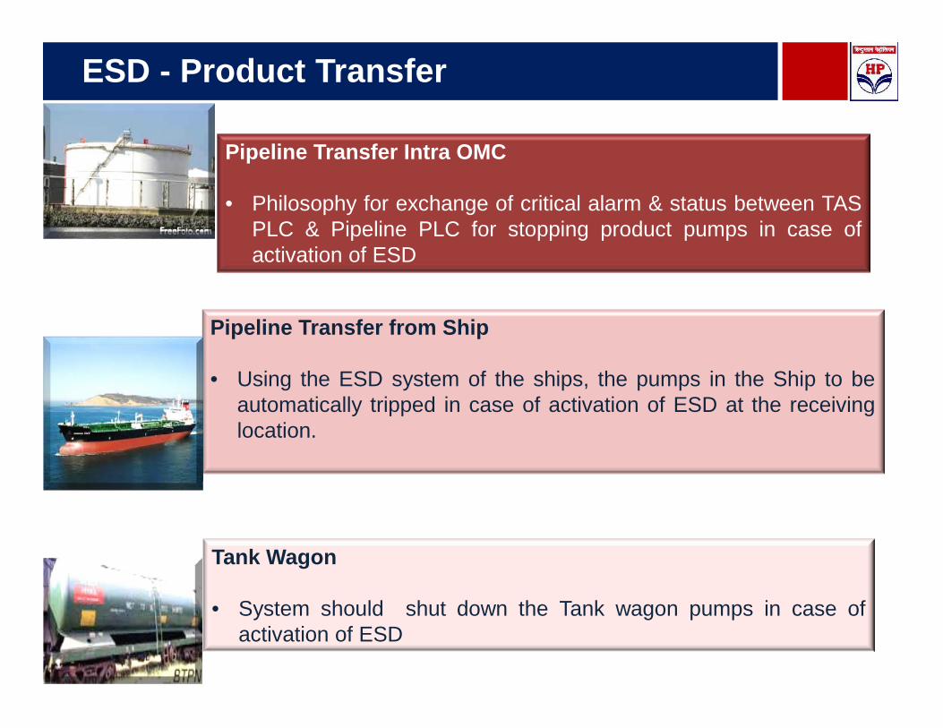
ESD - Product Transfer
Pipeline Transfer Intra OMC
• Philosophy for exchange of critical alarm & status between TASPLC & Pipeline PLC for stopping product pumps in case ofactivation of ESD
Pipeline Transfer from Ship
• Using the ESD system of the ships, the pumps in the Ship to beautomatically tripped in case of activation of ESD at the receivinglocation.
Tank Wagon
• System should shut down the Tank wagon pumps in case ofactivation of ESD

Plan of Presentation
Rim Seal Protection System2
HC Monitoring System3
Tank Appurtenances & OverfillProtection System
1
RIM Seal Protection System
RIM Seal
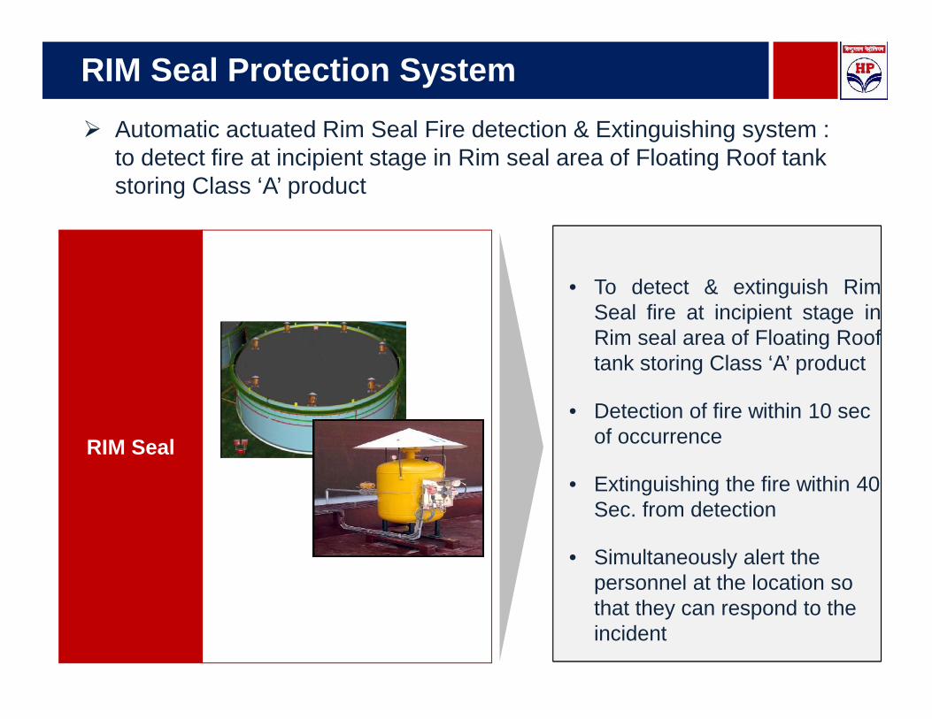
• To detect & extinguish RimSeal fire at incipient stage inRim seal area of Floating Rooftank storing Class ‘A’ product
• Detection of fire within 10 secof occurrence
• Extinguishing the fire within 40Sec. from detection
• Simultaneously alert thepersonnel at the location sothat they can respond to theincident
Automatic actuated Rim Seal Fire detection & Extinguishing system :to detect fire at incipient stage in Rim seal area of Floating Roof tankstoring Class ‘A’ product
Components of Rim Seal System
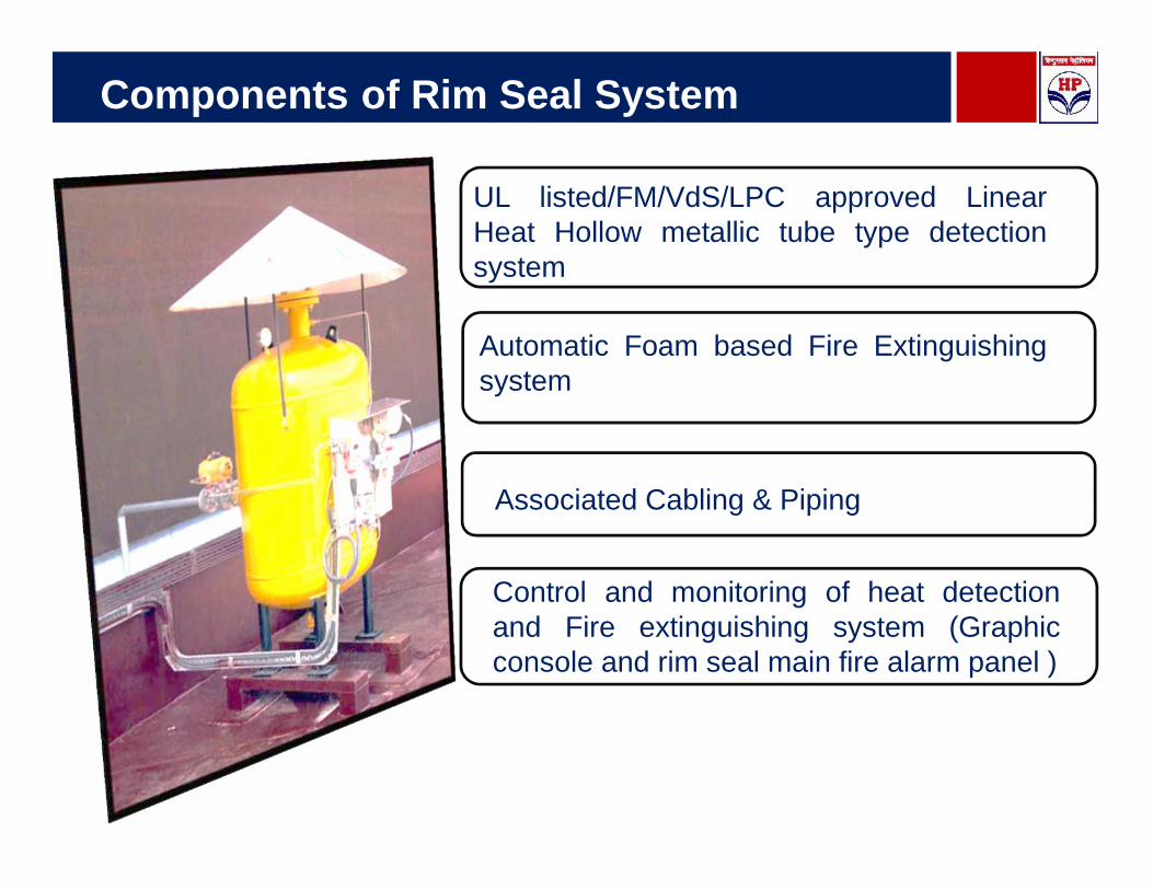
UL listed/FM/VdS/LPC approved LinearHeat Hollow metallic tube type detectionsystem
Automatic Foam based Fire Extinguishingsystem
Associated Cabling & Piping
Control and monitoring of heat detectionand Fire extinguishing system (Graphicconsole and rim seal main fire alarm panel )
Operating Conditions
Suitable for operating in humid and corrosive atmospheresfound in oil terminals, refineries & petrochemical plants inIndia
Suitable for working in relative humidity upto 95% (noncondensing) & temperature range of +1 deg C to +65deg C.
Tolerant to influences such as electromagneticinterference, Radio Frequency Interference (RFI),aggressive or corrosive vapour, UV radiation, andheavy rainfall & electrical surge
All enclosures for electrical equipment shall be suitable foruse in Zone 1, Gas group IIA/IIB as per hazardous areaclassification & approved by PESO India

Plan of Presentation
Rim Seal Protection System2
HC Monitoring System3
Tank Appurtenances & OverfillProtection System
1
Hydrocarbon Detectors
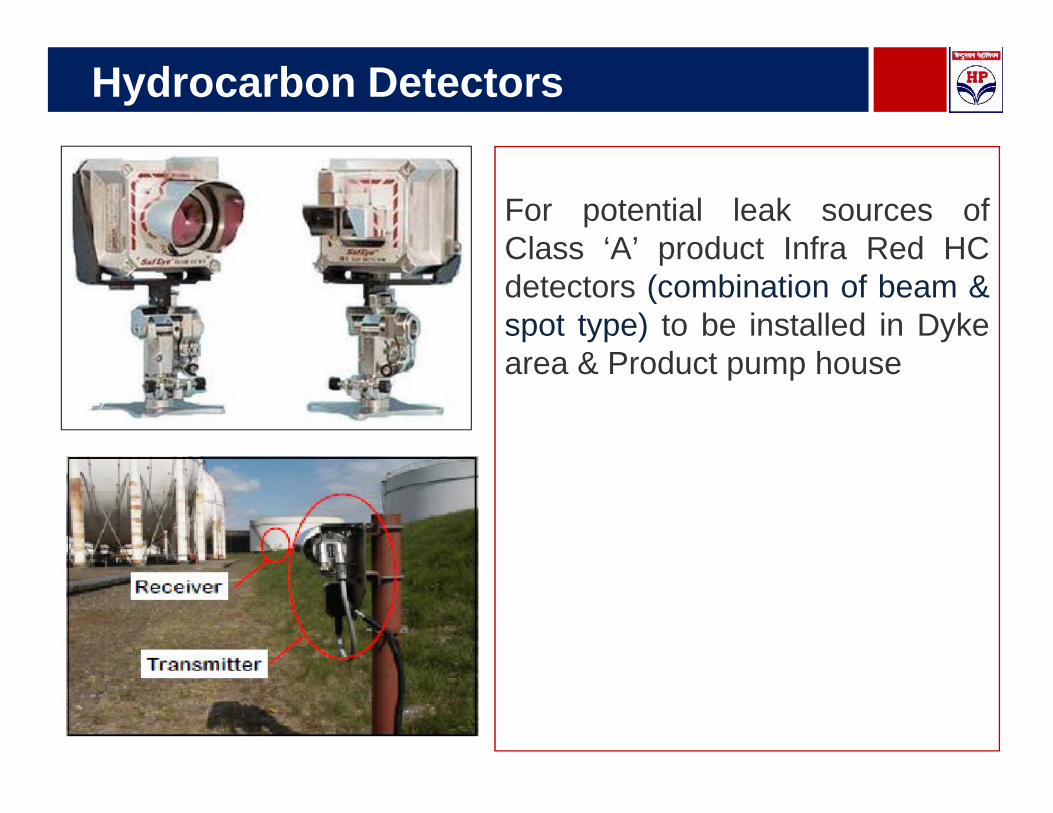
For potential leak sources ofClass ‘A’ product Infra Red HCdetectors (combination of beam &spot type) to be installed in Dykearea & Product pump house
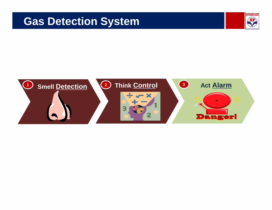
Gas Detection System
33Smell Detection11 Think Control22 Act Alarm

Philosophy of HCD SystemArea Type of Detector Nos.
Tank dyke storingClass ‘A’ products :
1. Across the manifoldon drain
2. On the collectionsump/drain pit
Open path GasDetector
Point type GasDetector or
Liquid type HC detector
One no.(min)
One no.(min)
1.PumpHousehandling Class ‘A’products
Open PathGas Detector One no.(min)
Conclusion
Process design shall be based on Risk Assessment Study
All Critical Equipments like Radar Gauges, Level switches shallbe SIL certified
Safe Tank farm operation , which integrates advancedtechnology and the people who interact with that technologyto help achieve the Safe objectives
Tank farm being the critical part of an Installation, by avoidingany possible risk to tank farm we create a Safe WorkEnvironment

ThankYou
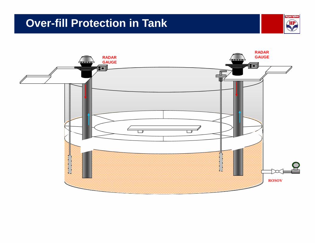
Over-fill Protection in Tank
MRTD
RADARGAUGERADAR
GAUGE
ROSOV