pollution prevention in the paints and coatings industryinfohouse.p2ric.org/ref/03/02175.pdf · 1.1...
TRANSCRIPT
United States Office of ResearchEnvironmental Protection and DevelopmentAgency Washington, DC 20460
EPA/625/R-96/003September 1996
Manual
Pollution Prevention in thePaints and CoatingsIndustry

EPA/625/R-96/003September 1996
Manual
Pollution Prevention in the Paints and Coatings Industry
U.S. Environmental Protection AgencyOffice of Research and Development
National Risk Management Research LaboratoryCenter for Environmental Research Information
Cincinnati, Ohio
Printed on Recycled Paper

DISCLAIMER
The U.S. Environmental Protection Agency through its Office of Research and Developmentfunded and managed the research described here under Contract #68-3-0315 to Eastern Research Group,Inc. It has been subjected to the Agency’s peer and administrative review and has been approved forpublication as an EPA document. Mention of trade names or commercial products does not constituteendorsement or recommendation for use.
FOREWORD
The U.S. Environmental Protection Agency is charged by Congress with protecting the Nation’sland, air, and water resources. Under a mandate of national environmental laws, the Agency strives toformulate and implement actions leading to a compatible balance between human activities and the abilityof natural systems to support and nurture life. To meet this mandate, EPA’s research program is providingdata and technical support for solving environmental problems today and building a science knowledgebase necessary to manage our ecological resources wisely, understand how pollutants affect our health,and prevent or reduce environmental risks in the future.
The National Risk Management Research Laboratory is the Agency’s center for investigation oftechnological and management approaches for reducing risks from threats to human health and theenvironment. The focus of the Laboratory’s research program is on methods for the prevention and controlof pollution to air, land, water and subsurface resources; protection of water quality in public water systems;remediation of contaminated sites and ground water; and prevention and control of indoor air pollution. Thegoal of this research effort is to catalyze development and implementation of innovative, cost-effectiveenvironmental technologies; develop scientific and engineering information needed by EPA to supportregulatory and policy implementation of environmental regulations and strategies.
This publication has been produced as part of the Laboratory’s strategic long-term research plan.It is published and made available by EPA’s Office of Research and Development to assist the usercommunity and to link researchers with their clients.
This manual, Pollution Prevention in the Paints and Coatings Industry, funded through the Centerfor Environmental Research Information, is a pollution prevention guidance manual for processes andwaste reduction in paints and coatings industry.
E. Timothy Oppelt, DirectorNational Risk Management Research Laboratory
. . .III

ABSTRACT
The paints and coatings industry represents a significant source of multimedia pollution through thewide use of solvent-based process materials and the extensive amounts of wastewater generated by theoperations. This manual presents recommended practices for minimizing the generation of pollution in thisindustry.
Regulations emphasizing source reduction of pollutants at the federal, state, and local level, aredriving facility operators to investigate the use of alternative cleaning formulations and paint systems.Aqueous degreasers and powder coatings are two examples of efforts to reduce toxic air emissions andcontrol costs associated with the treatment of contaminated effluent.
Many small and mid-sized facilities have few opportunities to take advantage of technology transferwithin the industry. The information in this manual can help operators assess operations and processes forpollution prevention options in using “cleaner” technologies and more efficient management practices.Suggestions contained within this manual can guide improvements in quality and efficiency, indirectlyimpacting prevention in terms of reduced wastes.
The manual has three general sections:
l An overview of the industry and an introduction to pollution prevention for paintsand coatings operations;
l Pollution prevention considerations;
l Case studies emphasizing approaches for reducing process waste.
Appendixes provide a list of suppliers of aqueous and semi-aqueous degreasers and equipment,methodology for specified dilution ratio calculations, and a spreadsheet for factoring transfer efficiencyconsiderations into application processes.
The audience for this document are facility operators and managers, manufacturing processmanagers, painters, and environmental engineers. Small and medium-size facilities that do not haveprocess engineers on staff have much to gain by implementing recommendations in this manual.
This report was submitted in fulfillment of Contract #68-3-0315 by Eastern Research Group, Inc.under the sponsorship of the U.S. Environmental Protection Agency. This report covers a period fromDecember, 1993, to September, 1996, and work was completed as of September 30, 1996.
iv
Contents
Page
Foreword . . . . . . . . . . . . . . . . . . . . . . . . . . . . . . . . . . . . . . . . . . . . . . . . . . . . . . . . . . . . . . . . . . . . iii
Abstract . . . . . . . . . . . . . . . . . . . . . . . . . . . . . . . . . . . . . . . . . . . . . . . . . . . . . . . . . . . . . . . . . . . . . iv
Figures . . . . . . . . . . . . . . . . . . . . . . . . . . . . . . . . . . . . . . . . . . . . . . . . . . . . . . . . . . . . . . . . . . . . . . xiv
Tables . . . . . . . . . . . . . . . . . . . . . . . . . . . . . . . . . . . . . . . . . . . . . . . . . . . . . . . . . . . . . . . . . . . . . . . xvi
Conversion Factors . . . . . . . . . . . . . . . . . . . . . . . . . . . . . . . . . . . . . . . . . . . . . . . . . . . . . . . . . . . . xviii
Acknowledgments.. . . . . . . . . . . . . . . . . . . . . . . . . . . . . . . . . . . . . . . . . . . . . . . . . . . . . . . . . . . . xix
SECTION 1 Overview . . . . . . . . . . . . . . . . . . . . . . . . . . . . . . . . . . . . . . . . . . . . . . . . . . . . . . . . . . . . . . . . . . . . 1
Chapter 1 Introduction.. . . . . . . . . . . . . . . . . . . . . . . . . . . . . . . . . . . . . . . . . . . . . . . . . . . . . . . . . . . . . . . . 2
1.1 Pollution Prevention in the Paints and Coatings Industry . . . . . . . . . . . . . . . . . . . . . . . . . . 2
1.2 The Audience for This Document. . . . . . . . . . . . . . . . . . . . . . . . . . . . . . . . . . . . . . . . . . . . . 2
1.3 The Organization of This Document. . . . . . . . . . . . . . . . . . . . . . . . . . . . . . . . . . . . . . . . . . . 2
Chapter 2 Overview of Paints and Coatings Operations . . . . . . . . . . . . . . . . . . . . . . . . . . . . . . . . . . . . . 4
2.1
2.2
2.3
2.4
2.5
Introduction.. . . . . . . . . . . . . . . . . . . . . . . . . . . . . . . . . . . . . . . . . . . . . . . . . . . . . . . . . . . . . 4
Operations for Miscellaneous Metal Workpieces. . . . . . . . . . . . . . . . . . . . . . . . . . . . . . . . . 4
2.2.1 Priming Only. . . . . . . . . . . . . . . . . . . . . . . . . . . . . . . . . . . . . . . . . . . . . . . . . . . . . . . 4
2.2.2 Priming and Topcoating. . . . . . . . . . . . . . . . . . . . . . . . . . . . . . . . . . . . . . . . . . . . . . 5
2.2.3 Surface Preparation . . . . . . . . . . . . . . . . . . . . . . . . . . . . . . . . . . . . . . . . . . . . . . . . . 7
2.2.4 Application of Paint Coating Systems. . . . . . . . . . . . . . . . . . . . . . . . . . . . . . . . . . . 9
2.2.5 Abatement Equipment. . . . . . . . . . . . . . . . . . . . . . . . . . . . . . . . . . . . . . . . . . . . . . . 9
Operations for the Automotive Industry . . . . . . . . . . . . . . . . . . . . . . . . . . . . . . . . . . . . . . . . 10
2.3.1 Process Overview . . . . . . . . . . . . . . . . . . . . . . . . . . . . . . . . . . . . . . . . . . . . . . . . . . 10
2.3.2 Paint Coating Systems and Application Processes . . . . . . . . . . . . . . . . . . . . . . . . 10
2.3.3 Abatement Equipment. . . . . . . . . . . . . . . . . . . . . . . . . . . . . . . . . . . . . . . . . . . . . . . 12
Operations for Plastic Parts . . . . . . . . . . . . . . . . . . . . . . . . . . . . . . . . . . . . . . . . . . . . . . . . . 12
2.4.1 Surface Preparation . . . . . . . . . . . . . . . . . . . . . . . . . . . . . . . . . . . . . . . . . . . . . . . . . 12
2.4.2 Coatings Systems . . . . . . . . . . . . . . . . . . . . . . . . . . . . . . . . . . . . . . . . . . . . . . . . . . 12
2.4.3 Application Equipment. . . . . . . . . . . . . . . . . . . . . . . . . . . . . . . . . . . . . . . . . . . . . . . 12
2.4.4 Abatement Equipment . . . . . . . . . . . . . . . . . . . . . . . . . . . . . . . . . . . . . . . . . . . . . . . 13
Custom Coating Operations. . . . . . . . . . . . . . . . . . . . . . . . . . . . . . . . . . . . . . . . . . . . . . . . . 13
V

Contents (continued)
Page
2.6 References . . . . . . . . . . . . . . . . . . . . . . . . . . . . . . . . . . . . . . . . . . . . . . . . . . . . . . . . . . . . . . 13
2.7 Additional Reading . . . . . . . . . . . . . . . . . . . . . . . . . . . . . . . . . . . . . . . . . . . . . . . . . . . . . . . . 13
SECTION 2 Pretreatment Factors. . . . . . . . . . . . . . . . . . . . . . . . . . . . . . . . . . . . . . . . . . . . . . . . . . . . . . . . . . 15
Chapter 3 Adhesion as a Critical Factor . . . . . . . . . . . . . . . . . . . . . . . . . . . . . . . . . . . . . . . . . . . . . . . . . . 16
3.1 Introduction . . . . . . . . . . . . . . . . . . . . . . . . . . . . . . . . . . . . . . . . . . . . . . . . . . . . . . . . . . . . . . 16
3.1.1 Pollution Prevention Considerations . . . . . . . . . . . . . . . . . . . . . . . . . . . . . . . . . . . . 16
3.2 Corrosion of Metals and Alloys. . . . . . . . . . . . . . . . . . . . . . . . . . . . . . . . . . . . . . . . . . . . . . . 16
3.2.1 Basics of the Corrosion Process. . . . . . . . . . . . . . . . . . . . . . . . . . . . . . . . . . . . . . . 16
3.2.2 The Science Behind Corrosion . . . . . . . . . . . . . . . . . . . . . . . . . . . . . . . . . . . . . . . . 17
3.2.3 Fundamentals of Corrosion Prevention. . . . . . . . . . . . . . . . . . . . . . . . . . . . . . . . . . 18
3.3 Preventing Corrosion by Ensuring Proper Adhesion . . . . . . . . . . . . . . . . . . . . . . . . . . . . . . 18
3.3.1 Mechanisms of Adhesion . . . . . . . . . . . . . . . . . . . . . . . . . . . . . . . . . . . . . . . . . . . . . 18
3.3.2 The Importance of Proper Wetting . . . . . . . . . . . . . . . . . . . . . . . . . . . . . . . . . . . . . 18
3.3.3 The Role of Surface Contaminants. . . . . . . . . . . . . . . . . . . . . . . . . . . . . . . . . . . . . 19
3.4 Adhesion Considerations Specific to Plastic Substrates . . . . . . . . . . . . . . . . . . . . . . . . . . . 21
3.5 References . . . . . . . . . . . . . . . . . . . . . . . . . . . . . . . . . . . . . . . . . . . . . . . . . . . . . . . . . . . . . . 21
Chapter 4 Considerations Regarding Vendor-Supplied Materials. . . . . . . . . . . . . . . . . . . . . . . . . . . . . . 23
4.1 Introduction . . . . . . . . . . . . . . . . . . . . . . . . . . . . . . . . . . . . . . . . . . . . . . . . . . . . . . . . . . . . . . 23
4.1.1 Pollution Prevention Considerations . . . . . . . . . . . . . . . . . . . . . . . . . . . . . . . . . . . . 23
4.1.2 Decision-Making Criteria . . . . . . . . . . . . . . . . . . . . . . . . . . . . . . . . . . . . . . . . . . . . . 23
4.2 Raw Materials . . . . . . . . . . . . . . . . . . . . . . . . . . . . . . . . . . . . . . . . . . . . . . . . . . . . . . . . . . . . 23
4.2.1 Protective Coatings and Treatments. . . . . . . . . . . . . . . . . . . . . . . . . . . . . . . . . . . . 23
4.2.2 Storage . . . . . . . . . . . . . . . . . . . . . . . . . . . . . . . . . . . . . . . . . . . . . . . . . . . . . . . . . . . 24
4.3 Componentsand Pans . . . . . . . . . . . . . . . . . . . . . . . . . . . . . . . . . . . . . . . . . . . . . . . . . . . . . 24
4.3.1 Protective Coatings and Primers. . . . . . . . . . . . . . . . . . . . . . . . . . . . . . . . . . . . . . . 24
4.3.2 Storage . . . . . . . . . . . . . . . . . . . . . . . . . . . . . . . . . . . . . . . . . . . . . . . . . . . . . . . . . . . 25
4.4 Just-in-Time Delivery. . . . . . . . . . . . . . . . . . . . . . . . . . . . . . . . . . . . . . . . . . . . . . . . . . . . . . . 25
4.5 References . . . . . . . . . . . . . . . . . . . . . . . . . . . . . . . . . . . . . . . . . . . . . . . . . . . . . . . . . . . . . . 25
Chapter 5 Surface Degreasing: Alternatives to Conventional Solvent-Based Methods. . . . . . . . . . . . 26
5.1 Introduction.. . . . . . . . . . . . . . . . . . . . . . . . . . . . . . . . . . . . . . . . . . . . . . . . . . . . . . . . . . . . . 26
5.1 .l Pollution Prevention Considerations . . . . . . . . . . . . . . . . . . . . . . . . . . . . . . . . . . . . 26
5.1.2 Decision-Making Criteria . . . . . . . . . . . . . . . . . . . . . . . . . . . . . . . . . . . . . . . . . . . . . 26
5.2 Basic Practices and Regulatory Considerations . . . . . . . . . . . . . . . . . . . . . . . . . . . . . . . . . 26
5.2.1 Typical Oils and Grime on Substrates . . . . . . . . . . . . . . . . . . . . . . . . . . . . . . . . . . 26
vi

Contents (continued)
Page
5.2.2 Basic Cleaning Approaches. . . . . . . . . . . . . . . . . . . . . . . . . . . . . . . . . . . . . . . . . . . 28
5.2.3 Selecting a Cleaning Approach. . . . . . . . . . . . . . . . . . . . . . . . . . . . . . . . . . . . . . . . 28
5.2.4 Regulatory Overview . . . . . . . . . . . . . . . . . . . . . . . . . . . . . . . . . . . . . . . . . . . . . . . . 29
5.3 Solvent-Based Methods.. . . . . . . . . . . . . . . . . . . . . . . . . . . . . . . . . . . . . . . . . . . . . . . . . . . 29
5.3.1 Vapor-Solvent Degreasing . . . . . . . . . . . . . . . . . . . . . . . . . . . . . . . . . . . . . . . . . . . . 29
5.3.2 Degreasing With Liquid Solvent (Cold Cleaning and Solvent Wiping). . . . . . . . . . 32
5.4 Aqueous Methods . . . . . . . . . . . . . . . . . . . . . . . . . . . . . . . . . . . . . . . . . . . . . . . . . . . . . . . . . 34
5.4.1 Aqueous Degreasing . . . . . . . . . . . . . . . . . . . . . . . . . . . . . . . . . . . . . . . . . . . . . . . . 34
5.4.2 Semi-aqueous Degreasing. . . . . . . . . . . . . . . . . . . . . . . . . . . . . . . . . . . . . . . . . . . . 37
5.5 Case Examples . . . . . . . . . . . . . . . . . . . . . . . . . . . . . . . . . . . . . . . . . . . . . . . . . . . . . . . . . . . 38
5.5.1 Frame Manufacturer. . . . . . . . . . . . . . . . . . . . . . . . . . . . . . . . . . . . . . . . . . . . . . . . . 38
5.5.2 Military Contractor . . . . . . . . . . . . . . . . . . . . . . . . . . . . . . . . . . . . . . . . . . . . . . . . . . 39
5.5.3 Lift Truck Manufacturer . . . . . . . . . . . . . . . . . . . . . . . . . . . . . . . . . . . . . . . . . . . . . . 39
5.6 References.. . . . . . . . . . . . . . . . . . . . . . . . . . . . . . . . . . . . . . . . . . . . . . . . . . . . . . . . . . . . . 40
Chapter 6 Phosphating Metal Surfaces: Process Efficiency and Waste Minimization. . . . . . . . . . . . . 41
6.1 Introduction.. . . . . . . . . . . . . . . . . . . . . . . . . . . . . . . . . . . . . . . . . . . . . . . . . . . . . . . . . . . . . 41
6.1.1 Pollution Prevention Considerations . . . . . . . . . . . . . . . . . . . . . . . . . . . . . . . . . . . . 41
6.1.2 Decision-Making Criteria . . . . . . . . . . . . . . . . . . . . . . . . . . . . . . . . . . . . . . . . . . . . . 41
6.2 Process Basics and Best Management Practices. . . . . . . . . . . . . . . . . . . . . . . . . . . . . . . . 41
6.2.1 Introduction . . . . . . . . . . . . . . . . . . . . . . . . . . . . . . . . . . . . . . . . . . . . . . . . . . . . . . . . 41
6.2.2 Coating Quality and Basic Parameters. . . . . . . . . . . . . . . . . . . . . . . . . . . . . . . . . . 44
6.2.3 Best Management Practices . . . . . . . . . . . . . . . . . . . . . . . . . . . . . . . . . . . . . . . . . . 45
6 . 3 P h o s p h a t i n g M e t h o d s . . . . . . . . . . . . . . . . . . . . . . . . . . . . . . . . . . . . . . . . . . . . . . . . 45
6.3.1 Iron Phosphating . . . . . . . . . . . . . . . . . . . . . . . . . . . . . . . . . . . . . . . . . . . . . . . . . . . 45
6.3.2 Zinc Phosphating . . . . . . . . . . . . . . . . . . . . . . . . . . . . . . . . . . . . . . . . . . . . . . . . . . . 47
6.3.3 Wash Primers as an Alternative to Phosphating. . . . . . . . . . . . . . . . . . . . . . . . . . . 48
6.4 Waste Minimization and Treatment . . . . . . . . . . . . . . . . . . . . . . . . . . . . . . . . . . . . . . . . . . . 48
6.4.1 Minimization . . . . . . . . . . . . . . . . . . . . . . . . . . . . . . . . . . . . . . . . . . . . . . . . . . . . . . . 48
6.4.2 Treatment . . . . . . . . . . . . . . . . . . . . . . . . . . . . . . . . . . . . . . . . . . . . . . . . . . . . . . . . . 49
6.5 Additional Considerations Related to Phosphating . . . . . . . . . . . . . . . . . . . . . . . . . . . . . . . 49
6.5.1 Choosing a Phosphate Formulation and Qualifying the Phosphate Coating. . . . . 49
6.5.2 Degreasing Before Phosphating . . . . . . . . . . . . . . . . . . . . . . . . . . . . . . . . . . . . . . . 49
6.5.3 Design of an Immersion Tank System . . . . . . . . . . . . . . . . . . . . . . . . . . . . . . . . . . 50
6.5.4 Design of a Spray Washer System. . . . . . . . . . . . . . . . . . . . . . . . . . . . . . . . . . . . . 50
6.5.5 Process and Quality Control Measures. . . . . . . . . . . . . . . . . . . . . . . . . . . . . . . . . . 51
vii

Contents (continued)
Page
6.6 References.. . . . . . . . . . . . . . . . . . . . . . . . . . . . . . . . . . . . . . . . . . . . . . . . . . . . . . . . . . . . . 51
6.7 Additional Reading.. . . . . . . . . . . . . . . . . . . . . . . . . . . . . . . . . . . . . . . . . . . . . . . . . . . . . . 52
Chapter 7 Rinsing Process Efficiency and Alternatives to Chromate-Based Sealers . . . . . . . . . . . . . 53
7.1 Introduction . . . . . . . . . . . . . . . . . . . . . . . . . . . . . . . . . . . . . . . . . . . . . . . . . . . . . . . . . . . . . . 53
7.1.1 Pollution Prevention Considerations . . . . . . . . . . . . . . . . . . . . . . . . . . . . . . . . . . . . 53
7.1.2 Decision-Making Criteria . . . . . . . . . . . . . . . . . . . . . . . . . . . . . . . . . . . . . . . . . . . . . 53
7.2 Rinsing . . . . . . . . . . . . . . . . . . . . . . . . . . . . . . . . . . . . . . . . . . . . . . . . . . . . . . . . . . . . . . . . . 53
7.2.1 Rinsing Basics and Best Management Practices. . . . . . . . . . . . . . . . . . . . . . . . . . 55
7.2.2 Counter-Flow Rinsing. . . . . . . . . . . . . . . . . . . . . . . . . . . . . . . . . . . . . . . . . . . . . . . . 57
7.3 Sealing . . . . . . . . . . . . . . . . . . . . . . . . . . . . . . . . . . . . . . . . . . . . . . . . . . . . . . . . . . . . . . . . . 59
7.3.1 Sealing Basics . . . . . . . . . . . . . . . . . . . . . . . . . . . . . . . . . . . . . . . . . . . . . . . . . . . . . 59
7.3.2 Chromate-Based Sealing Rinses Versus Nontoxic Alternatives. . . . . . . . . . . . . . . 60
7.4 Case Example . . . . . . . . . . . . . . . . . . . . . . . . . . . . . . . . . . . . . . . . . . . . . . . . . . . . . . . . . . . . 61
7.5 References.. . . . . . . . . . . . . . . . . . . . . . . . . . . . . . . . . . . . . . . . . . . . . . . . . . . . . . . . . . . . . 62
7.6 Additional Reading.. . . . . . . . . . . . . . . . . . . . . . . . . . . . . . . . . . . . . . . . . . . . . . . . . . . . . . . 62
Chapter 8 Abrasive Blast Cleaning of Metal Surfaces: Process Efficiency. . . . . . . . . . . . . . . . . . . . . . 63
8.1 Introduction.. . . . . . . . . . . . . . . . . . . . . . . . . . . . . . . . . . . . . . . . . . . . . . . . . . . . . . . . . . . . . 63
8.1.1 Pollution Prevention Considerations . . . . . . . . . . . . . . . . . . . . . . . . . . . . . . . . . . . . 63
8.1.2 Decision-Making Criteria . . . . . . . . . . . . . . . . . . . . . . . . . . . . . . . . . . . . . . . . . . . . . 63
8.2 Process Basics . . . . . . . . . . . . . . . . . . . . . . . . . . . . . . . . . . . . . . . . . . . . . . . . . . . . . . . . . . . 63
8.2.1 Introduction . . . . . . . . . . . . . . . . . . . . . . . . . . . . . . . . . . . . . . . . . . . . . . . . . . . . . . . . 63
8.2.2 Abrasive Blasting Systems . . . . . . . . . . . . . . . . . . . . . . . . . . . . . . . . . . . . . . . . . . . 64
8.2.3 Media Recycling. . . . . . . . . . . . . . . . . . . . . . . . . . . . . . . . . . . . . . . . . . . . . . . . . . . . 65
8.2.4 Blast Profile as a Critical Factor . . . . . . . . . . . . . . . . . . . . . . . . . . . . . . . . . . . . . . . 66
8.2.5 Types of Abrasive Media and Selection Criteria. . . . . . . . . . . . . . . . . . . . . . . . . . . 67
8.2.6 Blast Cleaning Standards . . . . . . . . . . . . . . . . . . . . . . . . . . . . . . . . . . . . . . . . . . . . 68
8.3 Best Management Practices . . . . . . . . . . . . . . . . . . . . . . . . . . . . . . . . . . . . . . . . . . . . . . . . . 69
8.4 Process Variations (With Case Examples). . . . . . . . . . . . . . . . . . . . . . . . . . . . . . . . . . . . . . 70
8.4.1 Abrasive Blasting Preceded by Degreasing . . . . . . . . . . . . . . . . . . . . . . . . . . . . . . 70
8.4.2 Abrasive Blasting Followed by Phosphating . . . . . . . . . . . . . . . . . . . . . . . . . . . . . . 71
8.5 References.. . . . . . . . . . . . . . . . . . . . . . . . . . . . . . . . . . . . . . . . . . . . . . . . . . . . . . . . . . . . . 71
SECTION 3 Application Process Factors . . . . . . . . . . . . . . . . . . . . . . . . . . . . . . . . . . . . . . . . . . . . . . . . . . . 73
Chapter 9 Transfer Efficiency as It Affects Air, Water, and Hazardous Waste Pollution . . . . . . . . . . . 74
9.1 Introduction.. . . . . . . . . . . . . . . . . . . . . . . . . . . . . . . . . . . . . . . . . . . . . . . . . . . . . . . . . . . . . 74
VIII
Contents (continued)
Page
9.1.1 Pollution Prevention Considerations . . . . . . . . . . . . . . . . . . . . . . . . . . . . . . . . . . . . 74
9.1.2 Decision-Making Criteria . . . . . . . . . . . . . . . . . . . . . . . . . . . . . . . . . . . . . . . . . . . . . 74
9.2 Benefits of Improved Transfer Efficiency . . . . . . . . . . . . . . . . . . . . . . . . . . . . . . . . . . . . . . . 74
9.2.1 Reductions in Pollution and Related Factors . . . . . . . . . . . . . . . . . . . . . . . . . . . . . 75
9.2.2 Reduction in Costs. . . . . . . . . . . . . . . . . . . . . . . . . . . . . . . . . . . . . . . . . . . . . . . . . . 76
9.3 Methods for Measuring Transfer Efficiency . . . . . . . . . . . . . . . . . . . . . . . . . . . . . . . . . . . . . 77
9.3.1 Defining Parameters Before Commencing the Transfer Efficiency Test. . . . . . . . . 77
9.3.2 Using the Weight (Mass) Method . . . . . . . . . . . . . . . . . . . . . . . . . . . . . . . . . . . . . . 78
9.3.3 Using the Volume Method. . . . . . . . . . . . . . . . . . . . . . . . . . . . . . . . . . . . . . . . . . . . 79
9.4 The Effects of Common Spray Guns on Transfer Efficiency. . . . . . . . . . . . . . . . . . . . . . . . 79
9.4.1 Conventional Air Atomizing Spray Guns. . . . . . . . . . . . . . . . . . . . . . . . . . . . . . . . . 79
9.4.2 High Volume, Low Pressure Air Atomizing Spray Guns. . . . . . . . . . . . . . . . . . . . . 79
9.4.3 Airless Spray Systems. . . . . . . . . . . . . . . . . . . . . . . . . . . . . . . . . . . . . . . . . . . . . . . 80
9.4.4 Air-Assisted Airless Spray Guns . . . . . . . . . . . . . . . . . . . . . . . . . . . . . . . . . . . . . . . 80
9.4.5 Electrostatic Spray Guns. . . . . . . . . . . . . . . . . . . . . . . . . . . . . . . . . . . . . . . . . . . . . 81
9.5 Pollution Prevention Strategies To Improve Transfer Efficiency . . . . . . . . . . . . . . . . . . . . . 81
9.5.1 Strategies That Require No Capital Expenditure . . . . . . . . . . . . . . . . . . . . . . . . . . 81
9.5.2 Strategies That Require Nominal Capital Expenditure. . . . . . . . . . . . . . . . . . . . . . 83
9.5.3 Strategies That Require Moderate or Significant Expenditure . . . . . . . . . . . . . . . . 85
9.6 References . . . . . . . . . . . . . . . . . . . . . . . . . . . . . . . . . . . . . . . . . . . . . . . . . . . . . . . . . . . . . . 85
9.7 Additional Reading.. . . . . . . . . . . . . . . . . . . . . . . . . . . . . . . . . . . . . . . . . . . . . . . . . . . . . . . 85
Chapter 10 Liquid Compliant Coating Technologies. . . . . . . . . . . . . . . . . . . . . . . . . . . . . . . . . . . . . . . . . . 86
10.1 In t roduct ion . . . . . . . . . . . . : . . . . . . . . . . . . . . . . . . . . . . . . . . . . . . . . . . . . . . . . . . . . . . . . . 86
10.1.1 Pollution Prevention Considerations . . . . . . . . . . . . . . . . . . . . . . . . . . . . . . . . . . . . 86
10.1.2 Decision-Making Criteria . . . . . . . . . . . . . . . . . . . . . . . . . . . . . . . . . . . . . . . . . . . . . 86
10.2 Guidelines for Choosing Best Management Practices . . . . . . . . . . . . . . . . . . . . . . . . . . . . 86
10.2.1 Liquid Versus Powder Coatings . . . . . . . . . . . . . . . . . . . . . . . . . . . . . . . . . . . . . . . 86
10.2.2 Water-Borne Versus Solvent-Borne Coatings . . . . . . . . . . . . . . . . . . . . . . . . . . . . . 90
10.2.3 Air/Force Dry Versus Bake . . . . . . . . . . . . . . . . . . . . . . . . . . . . . . . . . . . . . . . . . . . 90
10.2.4 Single-Component Versus Plural-Component. . . . . . . . . . . . . . . . . . . . . . . . . . . . . 90
10.3 Water-Borne Coatings. . . . . . . . . . . . . . . . . . . . . . . . . . . . . . . . . . . . . . . . . . . . . . . . . . . . . . 94
10.3.1 Overview . . . . . . . . . . . . . . . . . . . . . . . . . . . . . . . . . . . . . . . . . . . . . . . . . . . . . . . . . 94
10.3.2 Water-Borne Air/Force Dry Alkyds, Acrylics, Acrylic-Epoxy Hybrids. . . . . . . . . . . . 95
10.3.3 Water-Borne Epoxy Water-Reducible Air/Force Dried Coatings. . . . . . . . . . . . . . . 97
10.3.4 Polyurethane Dispersions . . . . . . . . . . . . . . . . . . . . . . . . . . . . . . . . . . . . . . . . . . . . 98
ix

Contents (continued)
Page
10.3.5 Water-Borne Baking Finishes-Alkyd, Alkyd-Modified, Acrylic, Polyester . . . . . . . 99
10.4 Solvent-Borne Coatings . . . . . . . . . . . . . . . . . . . . . . . . . . . . . . . . . . . . . . . . . . . . . . . . . . . . 100
10.4.1 Overview . . . . . . . . . . . . . . . . . . . . . . . . . . . . . . . . . . . . . . . . . . . . . . . . . . . . . . . . . 100
10.4.2 Solvent-Borne Alkyds and Modified Alkyds That Air or Force Dry. . . . . . . . . . . . . 100
10.4.3 Alkyd Derivative Combinations That Cure by Baking. . . . . . . . . . . . . . . . . . . . . . . 101
10.4.4 Catalyzed Epoxy Coatings. . . . . . . . . . . . . . . . . . . . . . . . . . . . . . . . . . . . . . . . . . . . 102
10.4.5 Catalyzed Two-Component Polyurethanes . . . . . . . . . . . . . . . . . . . . . . . . . . . . . . . 104
10.4.6 Moisture Curing Polyurethanes . . . . . . . . . . . . . . . . . . . . . . . . . . . . . . . . . . . . . . . . 105
10.5 Specialized Coatings. . . . . . . . . . . . . . . . . . . . . . . . . . . . . . . . . . . . . . . . . . . . . . . . . . . . . . . 105
10.5.1 Overview . . . . . . . . . . . . . . . . . . . . . . . . . . . . . . . . . . . . . . . . . . . . . . . . . . . . . . . . . 105
10.5.2 Autodeposition . . . . . . . . . . . . . . . . . . . . . . . . . . . . . . . . . . . . . . . . . . . . . . . . . . . . . 105
10.5.3 Electrodeposition . . . . . . . . . . . . . . . . . . . . . . . . . . . . . . . . . . . . . . . . . . . . . . . . . . . 107
10.5.4 Radiation Cured Coatings . . . . . . . . . . . . . . . . . . . . . . . . . . . . . . . . . . . . . . . . . . . . 108
10.5.5 Vapor Injection Cure . . . . . . . . . . . . . . . . . . . . . . . . . . . . . . . . . . . . . . . . . . . . . . . . 110
10.5.6 Supercritical CO2 for Paints and Coatings . . . . . . . . . . . . . . . . . . . . . . . . . . . . . . . 110
10.6 Emerging Technologies. . . . . . . . . . . . . . . . . . . . . . . . . . . . . . . . . . . . . . . . . . . . . . . . . . . . . 111
10.7 Selecting the Best Technology for Specific Applications . . . . . . . . . . . . . . . . . . . . . . . . . . . 112
10.8 References.. . . . . . . . . . . . . . . . . . . . . . . . . . . . . . . . . . . . . . . . . . . . . . . . . . . . . . . . . . . . . 112
10.9 Additional Reading . . . . . . . . . . . . . . . . . . . . . . . . . . . . . . . . . . . . . . . . . . . . . . . . . . . . . . . . 112
Chapter 11 Powder Coatings . . . . . . . . . . . . . . . . . . . . . . . . . . . . . . . . . . . . . . . . . . . . . . . . . . . . . . . . . . . . . 114
11.1 Introduction . . . . . . . . . . . . . . . . . . . . . . . . . . . . . . . . . . . . . . . . . . . . . . . . . . . . . . . . . . . . . . 114
11.1.1 Pollution Prevention Considerations . . . . . . . . . . . . . . . . . . . . . . . . . . . . . . . . . . . . 114
11.1.2 Decision-Making Criteria . . . . . . . . . . . . . . . . . . . . . . . . . . . . . . . . . . . . . . . . . . . . . 114
11.2 Suitability for Specific Applications. . . . . . . . . . . . . . . . . . . . . . . . . . . . . . . . . . . . . . . . . . . . 114
11.2.1 Suitable Applications . . . . . . . . . . . . . . . . . . . . . . . . . . . . . . . . . . . . . . . . . . . . . . . . 114
11.2.2 Unsuitable Applications . . . . . . . . . . . . . . . . . . . . . . . . . . . . . . . . . . . . . . . . . . . . . . 114
11.3 The Powder Coating Process. . . . . . . . . . . . . . . . . . . . . . . . . . . . . . . . . . . . . . . . . . . . . . . . 115
11.3.1 Applying the Coating . . . . . . . . . . . . . . . . . . . . . . . . . . . . . . . . . . . . . . . . . . . . . . . . 116
11.3.2 Curing the Coated Part . . . . . . . . . . . . . . . . . . . . . . . . . . . . . . . . . . . . . . . . . . . . . . 116
11.4 Costs Associated With Powder Coating. . . . . . . . . . . . . . . . . . . . . . . . . . . . . . . . . . . . . . . . 117
11.4.1 Profiles of Economic Impact of Switching to Powders. . . . . . . . . . . . . . . . . . . . . . 118
11.5 Advantages and Limitations of Powder Coatings . . . . . . . . . . . . . . . . . . . . . . . . . . . . . . . . 118
11.5.1 Advantages . . . . . . . . . . . . . . . . . . . . . . . . . . . . . . . . . . . . . . . . . . . . . . . . . . . . . . . 118
11.5.2 Limitations . . . . . . . . . . . . . . . . . . . . . . . . . . . . . . . . . . . . . . . . . . . . . . . . . . . . . . . . 119
11.6 References.. . . . . . . . . . . . . . . . . . . . . . . . . . . . . . . . . . . . . . . . . . . . . . . . . . . . . . . . . . . . . 119
X
Contents (continued)
Page
Chapter 12 Viscosity Management for Pollution Prevention.. ... . . . . . . . . . . . . . . . . . . . . . . . . . . . . . . . . 121
12.1 Introduction . . . . . . . . . . . . . . . . . . . . . . . . . . . . . . . . . . . . . . . . . . . . . . . . . . . . . . . . . . . . . . 121
12.1.1 Pollution Prevention Considerations . . . . . . . . . . . . . . . . . . . . . . . . . . . . . . . . . . . . 121
12.2 Description of Viscosity.... . . . . . . . . . . . . . . . . . . . . . . . . . . . . . . . . . . . . . . . . . . . . . . . . . . . . 121
12.3 Measuring Viscosity . . . . . . . . . . . . . . . . . . . . . . . . . . . . . . . . . . . . . . . . . . . . . . . . . . . . . . . 122
12.3.1 Zahn Cup . . . . . . . . . . . . . . . . . . . . . . . . . . . . . . . . . . . . . . . . . . . . . . . . . . . . . . . . . 122
12.3.2 Ford Cup.. . . . . . . . . . . . . . . . . . . . . . . . . . . . . . . . . . . . . . . . . . . . . . . . . . . . . . . . 123
12.3.3 Brookfield Viscometer . . . . . . . . . . . . . . . . . . . . . . . . . . . . . . . . . . . . . . . . . . . . . . . 124
12.4 Guidelines for Best Management Practices (BMPs) . . . . . . . . . . . . . . . . . . . . . . . . . . . . . . 125
12.4.1 Measuring Viscosity and Temperature . . . . . . . . . . . . . . . . . . . . . . . . . . . . . . . . . . 125
12.4.2 Specifying a Viscosity Range . . . . . . . . . . . . . . . . . . . . . . . . . . . . . . . . . . . . . . . . . 125
12.4.3 Developing Acceptable Alternatives. . . . . . . . . . . . . . . . . . . . . . . . . . . . . . . . . . . . . 126
12.4.4 Using Heat To Reduce Viscosity. . . . . . . . . . . . . . . . . . . . . . . . . . . . . . . . . . . . . . . 126
12.4.5 Minimizing Waste Disposal . . . . . . . . . . . . . . . . . . . . . . . . . . . . . . . . . . . . . . . . . . . 126
12.4.6 Recognizing Thixotropic Properties. . . . . . . . . . . . . . . . . . . . . . . . . . . . . . . . . . . . . 126
12.5 Managing Viscosity Differences for Different Coatings . . . . . . . . . . . . . . . . . . . . . . . . . . . . 127
12.6 Problems Associated With Viscosity Mismanagement. . . . . . . . . . . . . . . . . . . . . . . . . . . . . 128
12.6.1 Effect of Film Thickness Variations on Color, Gloss, and Drying Time . . . . . . . . . 128
12.6.2 Effect of Viscosity Differences on Metallic Colors. . . . . . . . . . . . . . . . . . . . . . . . . . 128
12.6.3 Effects of Too Low a Viscosity. . . . . . . . . . . . . . . . . . . . . . . . . . . . . . . . . . . . . . . . . 128
12.7 Strategies That Optimize Factors Affecting Viscosity . . . . . . . . . . . . . . . . . . . . . . . . . . . . . 129
12.7.1 Effect of Plural-Component, In-Line Mixing. . . . . . . . . . . . . . . . . . . . . . . . . . . . . . . 129
12.7.2 Effect of Dilutant (Reducer or Thinner) on Viscosity . . . . . . . . . . . . . . . . . . . . . . . 129
12.7.3 Effect of Temperature on Viscosity . . . . . . . . . . . . . . . . . . . . . . . . . . . . . . . . . . . . . 129
12.7.4 Effect of Batch Mixing of Plural-Component Coatings . . . . . . . . . . . . . . . . . . . . . . 131
12.7.5 Methods for Increasing the Pot-Life of Batch-Mixed Plural-ComponentCoatings . . . . . . . . . . . . . . . . . . . . . . . . . . . . . . . . . . . . . . . . . . . . . . . . . . . . . . . . . . 132
1 2 . 8 R e f e r e n c e s . . . . . . . . . . . . . . . . . . . . . . . . . . . . . . . . . . . . . . . . . . . . . . . . . . . . . . . . . . . . . . . 1 3 3
Chapter 13 Minimizing Solvent Usage for Equipment Clean-Up . . . . . . . . . . . . . . . . . . . . . . . . . . . . . . . . 134
13.1 Introduction . . . . . . . . . . . . . . . . . . . . . . . . . . . . . . . . . . . . . . . . . . . . . . . . . . . . . . . . . . . . . . 134
13.1.1 Pollution Prevention Considerations . . . . . . . . . . . . . . . . . . . . . . . . . . . . . . . . . . . . 134
13.1.2 Decision-Making Criteria . . . . . . . . . . . . . . . . . . . . . . . . . . . . . . . . . . . . . . . . . . . . . 134
13.2 Solvent Recycling . . . . . . . . . . . . . . . . . . . . . . . . . . . . . . . . . . . . . . . . . . . . . . . . . . . . . . . . . 134
13.3 Minimizing Emissions of Hazardous Air Pollutants . . . . . . . . . . . . . . . . . . . . . . . . . . . . . . . 135
13.3.1 Strategies To Minimize HAP Emissions . . . . . . . . . . . . . . . . . . . . . . . . . . . . . . . . . 136
xi
Contents (continued)
Page
13.4 Regulatory Provisions. . . . . . . . . . . . . . . . . . . . . . . . . . . . . . . . . . . . . . . . . . . . . . . . . . . . . . 136
13.4.1 South Coast Rule 1107, (b)(3-7). . . . . . . . . . . . . . . . . . . . . . . . . . . . . . . . . . . . . . . 136
13.5 Process for Cleaning Spray Guns and Fluid Hoses . . . . . . . . . . . . . . . . . . . . . . . . . . . . . 137
13.6 References . . . . . . . . . . . . . . . . . . . . . . . . . . . . . . . . . . . . . . . . . . . . . . . . . . . . . . . . . . . . . . 138
Chapter 14 Paint Stripping: Alternatives to Solvent-Based Methods. . . . . . . . . . . . . . . . . . . . . . . . . . . . 139
14.1 Introduction . . . . . . . . . . . . . . . . . . . . . . . . . . . . . . . . . . . . . . . . . . . . . . . . . . . . . . . . . . . . . . 139
14.1.1 Pollution Prevention Considerations . . . . . . . . . . . . . . . . . . . . . . . . . . . . . . . . . . . . 139
14.1.2 Decision-Making Criteria . . . . . . . . . . . . . . . . . . . . . . . . . . . . . . . . . . . . . . . . . . . . . 139
14.2 Process Basics . . . . . . . . . . . . . . . . . . . . . . . . . . . . . . . . . . . . . . . . . . . . . . . . . . . . . . . . . . . 139
14.3 Solvent-Based, Aqueous, and Semi-aqueous Methods. . . . . . . . . . . . . . . . . . . . . . . . . . . . 141
14.3.1 Solvent-Based Methods. . . . . . . . . . . . . . . . . . . . . . . . . . . . . . . . . . . . . . . . . . . . . . 141
14.3.2 Aqueous Methods.. . . . . . . . . . . . . . . . . . . . . . . . . . . . . . . . . . . . . . . . . . . . . . . . . 141
14.3.3 Semi-aqueous Methods. . . . . . . . . . . . . . . . . . . . . . . . . . . . . . . . . . . . . . . . . . . . . . 142
14.4 “Cleaner” Technologies: Alternatives to Conventional Methods. . . . . . . . . . . . . . . . . . . . . . 142
14.4.1 Impaction Methods. . . . . . . . . . . . . . . . . . . . . . . . . . . . . . . . . . . . . . . . . . . . . . . . . . 142
14.4.2 Abrasion Method . . . . . . . . . . . . . . . . . . . . . . . . . . . . . . . . . . . . . . . . . . . . . . . . . . . 144
14.4.3 Thermal Methods . . . . . . . . . . . . . . . . . . . . . . . . . . . . . . . . . . . . . . . . . . . . . . . . . . . 144
14.4.4 Cryogenic Methods . . . . . . . . . . . . . . . . . . . . . . . . . . . . . . . . . . . . . . . . . . . . . . . . . 146
14.5 References.. . . . . . . . . . . . . . . . . . . . . . . . . . . . . . . . . . . . . . . . . . . . . . . . . . . . . . . . . . . . . 146
Chapter 15 Minimizing Pollution in Spray Booths . . . . . . . . . . . . . . . . . . . . . . . . . . . . . . . . . . . . . . . . . . . 147
15.1 Introduction . . . . . . . . . . . . . . . . . . . . . . . . . . . . . . . . . . . . . . . . . . . . . . . . . . . . . . . . . . . . . . 147
15.1.1 Pollution Prevention Considerations . . . . . . . . . . . . . . . . . . . . . . . . . . . . . . . . . . . . 147
15.1.2 Decision-Making Criteria . . . . . . . . . . . . . . . . . . . . . . . . . . . . . . . . . . . . . . . . . . . . . 147
15.2 Definition and Function of Spray Booths. . . . . . . . . . . . . . . . . . . . . . . . . . . . . . . . . . . . . . . 147
15.3 Spray Booth Design . . . . . . . . . . . . . . . . . . . . . . . . . . . . . . . . . . . . . . . . . . . . . . . . . . . . . . . 148
15.3.1 Cross-Draft . . . . . . . . . . . . . . . . . . . . . . . . . . . . . . . . . . . . . . . . . . . . . . . . . . . . . . . . 149
15.3.2 Down Draft . . . . . . . . . . . . . . . . . . . . . . . . . . . . . . . . . . . . . . . . . . . . . . . . . . . . . . . . 150
15.3.3 Semi-down Draft . . . . . . . . . . . . . . . . . . . . . . . . . . . . . . . . . . . . . . . . . . . . . . . . . . . 151
15.4 Dry Filter Spray Booths . . . . . . . . . . . . . . . . . . . . . . . . . . . . . . . . . . . . . . . . . . . . . . . . . . . . 151
15.4.1 Advantages . . . . . . . . . . . . . . . . . . . . . . . . . . . . . . . . . . . . . . . . . . . . . . . . . . . . . . . 152
15.4.2 Disadvantages . . . . . . . . . . . . . . . . . . . . . . . . . . . . . . . . . . . . . . . . . . . . . . . . . . . . . 153
15.4.3 Selecting Dry Filter Media. . . . . . . . . . . . . . . . . . . . . . . . . . . . . . . . . . . . . . . . . . . . 153
15.5 Water-Wash Spray Booths . . . . . . . . . . . . . . . . . . . . . . . . . . . . . . . . . . . . . . . . . . . . . . . . . . 156
15.5.1 Advantages . . . . . . . . . . . . . . . . . . . . . . . . . . . . . . . . . . . . . . . . . . . . . . . . . . . . . . . 156
15.5.2 Disadvantages . . . . . . . . . . . . . . . . . . . . . . . . . . . . . . . . . . . . . . . . . . . . . . . . . . . . . 157
xii
Contents (continued)
Page
15.5.3 Selecting the Appropriate Chemicals . . . . . . . . . . . . . . . . . . . . . . . . . . . . . . . . . . . 157
15.5.4 Methods for Treating Water From Water-Wash Booths . . . . . . . . . . . . . . . . . . . . . 157
15.6 Baffle Booths . . . . . . . . . . . . . . . . . . . . . . . . . . . . . . . . . . . . . . . . . . . . . . . . . . . . . . . . . . . . . 158
15.7 Best Management Practices To Minimize Coating Defects in the Spray Booth . . . . . . . . . 158
15.7.1 Poor Wrap.. . . . . . . . . . . . . . . . . . . . . . . . . . . . . . . . . . . . . . . . . . . . . . . . . . . . . . . 158
15.7.2 Dust and Dirt in the Finish . . . . . . . . . . . . . . . . . . . . . . . . . . . . . . . . . . . . . . . . . . . 158
15.7.3 Water Spots in the Finish . . . . . . . . . . . . . . . . . . . . . . . . . . . . . . . . . . . . . . . . . . . . 158
15.7.4 Haziness That Detracts From the Gloss. . . . . . . . . . . . . . . . . . . . . . . . . . . . . . . . . 159
15.7.5 Dry Overspray on the Finish . . . . . . . . . . . . . . . . . . . . . . . . . . . . . . . . . . . . . . . . . . 159
15.7.6 Non-uniform Coating Finish With Gloss Patches, Orange Peel, Voids, etc. . . . . . 159
15.8 References . . . . . . . . . . . . . . . . . . . . . . . . . . . . . . . . . . . . . . . . . . . . . . . . . . . . . . . . . . . . . . 159
15.9 Additional Reading.. . . . . . . . . . . . . . . . . . . . . . . . . . . . . . . . . . . . . . . . . . . . . . . . . . . . . . . 159
SECTION 4 Problem Solving . . . . . . . . . . . . . . . . . . . . . . . . . . . . . . . . . . . . . . . . . . . . . . . . . . . . . . . . . . . . . 161
Chapter 16 Problem Solving: Case Studies of Some Typical Paint Facilities. . . . . . . . . . . . . . . . . . . . . 162
16.1 Introduction . . . . . . . . . . . . . . . . . . . . . . . . . . . . . . . . . . . . . . . . . . . . . . . . . . . . . . . . . . . . . . 162
16.2 Case Study #l: Flaking Paint on Tool Boxes . . . . . . . . . . . . . . . . . . . . . . . . . . . . . . . . . . . 162
16.2.1 Background of Problems. . . . . . . . . . . . . . . . . . . . . . . . . . . . . . . . . . . . . . . . . . . . . 162
16.2.2 Possible Solutions . . . . . . . . . . . . . . . . . . . . . . . . . . . . . . . . . . . . . . . . . . . . . . . . . . 162
16.2.3 Pollution Prevention Opportunities . . . . . . . . . . . . . . . . . . . . . . . . . . . . . . . . . . . . . 163
16.3 Case Study #2: High Reject Rate and VOC Emissions From Aluminum Lamp Housings. . . . . 164
16.3.1 Background of Problems . . . . . . . . . . . . . . . . . . . . . . . . . . . . . . . . . . . . . . . . . . . . . 164
16.3.2 Possible Solutions . . . . . . . . . . . . . . . . . . . . . . . . . . . . . . . . . . . . . . . . . . . . . . . . . . 164
16.3.3 Pollution Prevention Opportunities . . . . . . . . . . . . . . . . . . . . . . . . . . . . . . . . . . . . . 166
16.4 Case Study #3: Start-Up Problems for Automotive Component Manufacturer. . . . . . . . . . 166
16.4.1 Background of Problems . . . . . . . . . . . . . . . . . . . . . . . . . . . . . . . . . . . . . . . . . . . . 166
16.4.2 Possible Solutions . . . . . . . . . . . . . . . . . . . . . . . . . . . . . . . . . . . . . . . . . . . . . . . . . . 167
16.4.3 Pollution Prevention Opportunities . . . . . . . . . . . . . . . . . . . . . . . . . . . . . . . . . . . . . 169
16.5 Conclusion . . . . . . . . . . . . . . . . . . . . . . . . . . . . . . . . . . . . . . . . . . . . . . . . . . . . . . . . . . . . . . . 169
Appendix A Selected List of Suppliers of Aqueous and Semi-aqueous DegreaserFormulations and Equipment.. . . . . . . . . . . . . . . . . . . . . . . . . . . . . . . . . . . . . . . . . . . . . . . . . . 172
Appendix B How To Calculate the Flow Rate of Rinse Water Required To Achieve aSpecified Dilution Ratio . . . . . . . . . . . . . . . . . . . . . . . . . . . . . . . . . . . . . . . . . . . . . . . . . . . . . . .178
Appendix C Spreadsheet Model To Estimate Transfer Efficiency . . . . . . . . . . . . . . . . . . . . . . . . . . . . . . . 180
Index . . . . . . . . . . . . . . . . . . . . . . . . . . . . . . . . . . . . . . . . . . . . . . . . . . . . . . . . . . . . . . . . . . . . . . . . . . . . . . . . . . 183
XIII

Figures
Figure
2-l
2-2
2-3
2-4
2-5
2-6
2-7
2-8
3-1
3-2
3-3
3-4
3-5
3-6
5-l
5-2
6-1
6-2
6-3
7-1
7-2
7-3
7-4
7-5
7-6
8-1
9-l
9-2
9-3
9-4
9-5
10-l
10-2
12-1
12-2
Schematic of a typical process for priming metal parts. . . . . . . . . . . . . . . . . . . . . . . . . . . . . . . . . . . . . . . . . 5
Schematic of a process for two-stage application of a primer-topcoat system. . . . . . . . . . . . . . . . . . . . . . . 7
Schematic of a process for single-stage application of a primer-topcoat system. . . . . . . . . . . . . . . . . . . . . 8
Schematic of a three-stage iron phosphating process. . . . . . . . . . . . . . . . . . . . . . . . . . . . . . . . . . . . . . . . . . 8
Schematic of a five-stage iron or zinc phosphating process. . . . . . . . . . . . . . . . . . . . . . . . . . . . . . . . . . . . . 9
Schematic of a typical conversion coating process for aluminum workpieces. . . . . . . . . . . . . . . . . . . . . . . 9
Schematic of a typical process for applying a primer-topcoat system in the automotive industry . . . . . . . . 11
Schematic of a typical process for applying a zinc phosphate coating in the automotive industry. . . . . . . 11
Movement of electrons and ions in corrosion process involving a galvanic couple . . . . . . . . . . . . . . . . . . . 17
Mechanism of corrosion on a steel substrate . . . . . . . . . . . . . . . . . . . . . . . . . . . . . . . . . . . . . . . . . . . . . . . 17
Coating contact angle relative to wetting of surface. . . . . . . . . . . . . . . . . . . . . . . . . . . . . . . . . . . . . . . . . . . 19
Cross-sectional view of surface wetting . . . . . . . . . . . . . . . . . . . . . . . . . . . . . . . . . . . . . . . . . . . . . . . . . . . .20
Cross-sectional view of surface spalling caused by scale . . . . . . . . . . . . . . . . . . . . . . . . . . . . . . . . . . . . . . 20
Cross-sectional view of compromising effect of weld slag and spatters on a coating . . . . . . . . . . . . . . . . . 21
Schematic of a typical solvent vapor degreasing process . . . . . . . . . . . . . . . . . . . . . . . . . . . . . . . . . . . . . 31
Schematic of a typical cold cleaning degreasing process . . . . . . . . . . . . . . . . . . . . . . . . . . . . . . . . . . . . . . 33
Cross-sectional view of conversion coating process using iron or zinc phosphate. . . . . . . . . . . . . . . . . . . 43
Immersion rinse system schematic. . . . . . . . . . . . . . . . . . . . . . . . . . . . . . . . . . . . . . . . . . . . . . . . . . . . . . .50
Schematic of a conveyorized paints and coatings operation . . . . . . . . . . . . . . . . . . . . . . . . . . . . . . . . . . . . 51
Schematic of three-step post-degreasing rinse stage. . . . . . . . . . . . . . . . . . . . . . . . . . . . . . . . . . . . . . . . . 56
Schematic of counter-flow rinsing . . . . . . . . . . . . . . . . . . . . . . . . . . . . . . . . . . . . . . . . . . . . . . . . . . . . . . . . . 58
Dilution ratio as a function of time for-different tank sizes . . . . . . . . . . . . . . . . . . . . . . . . . . . . . . . . . . . . . 58
Graph of rinse water flow rate required to dilute drag-in stream at 1 gal/min for first rinse bath only . . . . . 60
Graph of counter-flow rinse water flow rate required to dilute drag-in stream at 1 gal/min fors u b s e q u e n t r i n s e b a t h s . . . . . . . . . . . . . . . . . . . . . . . . . . . . . . . . . . . . . . . . . . . . . . . . . . . . . . . . . . . . . . . . . 6 0
Schematic of post-phosphating rinsing process with sealing rinse bath. . . . . . . . . . . . . . . . . . . . . . . . . . . 60
Schematic of an abrasive blasting operation with a media recovery system . . . . . . . . . . . . . . . . . . . . . . . . 65
Effect of transfer efficiency on VOC emissions. . . . . . . . . . . . . . . . . . . . . . . . . . . . . . . . . . . . . . . . . . . . . . 77
Effect of fluid flow rate on residence time in gun . . . . . . . . . . . . . . . . . . . . . . . . . . . . . . . . . . . . . . . . . . . . . 82
E f f e c t o f f a n w i d t h . . . . . . . . . . . . . . . . . . . . . . . . . . . . . . . . . . . . . . . . . . . . . . . . . . . . . . . . . . . . . . . . . . . 8 2
Effect of leading and trailing edges on transfer efficiency. . . . . . . . . . . . . . . . . . . . . . . . . . . . . . . . . . . . . .83
Deliberate overspray at top of first stroke and bottom of last stroke. . . . . . . . . . . . . . . . . . . . . . . . . . . . . . 84
VOCs in water-borne coatings. . . . . . . . . . . . . . . . . . . . . . . . . . . . . . . . . . . . . . . . . . . . . . . . . . . . . . . . . . .95
Hardness scale for solvent-borne coatings. . . . . . . . . . . . . . . . . . . . . . . . . . . . . . . . . . . . . . . . . . . . . . . . 102
The concept of viscosity (2). . . . . . . . . . . . . . . . . . . . . . . . . . . . . . . . . . . . . . . . . . . . . . . . . . . . . . . . . . . . 121
T h i x o t r o p y . . . . . . . . . . . . . . . . . . . . . . . . . . . . . . . . . . . . . . . . . . . . . . . . . . . . . . . . . . . . . . . . . . . . . . . . . . . . . l 2 2
xiv

Figures (continued)
Figure Page
12-3
12-4 Ford viscosity cups.. . . . . . . . . . . . . . . . . . . . . . . . . . . . . . . . . . . . . . . . . . . . . . . . . . . . . . . . . . . . . . . . .124
12-5 Brookfield viscometer . . . . . . . . . . . . . . . . . . . . . . . . . . . . . . . . . . . . . . . . . . . . . . . . . . . . . . . . . . . . . . . . 124
12-6 Effect of solvent reduction on viscosity. . . . . . . . . . . . . . . . . . . . . . . . . . . . . . . . . . . . . . . . . . . . . . . . . . . . 127
12-7 Effect of reduction on viscosity for water-borne coatings . . . . . . . . . . . . . . . . . . . . . . . . . . . . . . . . . . . . . . 127
12-8 Plural-component proportioning system . . . . . . . . . . . . . . . . . . . . . . . . . . . . . . . . . . . . . . . . . . . . . . . . . . 130
12-9 Effect of solvents and diluents on viscosity. . . . . . . . . . . . . . . . . . . . . . . . . . . . . . . . . . . . . . . . . . . . . . . . 130
12-10 Effect of temperature on viscosity. . . . . . . . . . . . . . . . . . . . . . . . . . . . . . . . . . . . . . . . . . . . . . . . . . . . . . . 131
12-11 Effect of viscosity on single- and plural-component coatings. . . . . . . . . . . . . . . . . . . . . . . . . . . . . . . . . . . 132
12-12 Effect of temperature on pot-life of plural-component coatings. . . . . . . . . . . . . . . . . . . . . . . . . . . . . . . . . 132
13-1 Typical solvent distillation unit. . . . . . . . . . . . . . . . . . . . . . . . . . . . . . . . . . . . . . . . . . . . . . . . . . . . . . . . . . 135
13-2 T y p i c a l s p r a y g u n c l e a n e r . . . . . . . . . . . . . . . . . . . . . . . . . . . . . . . . . . . . . . . . . . . . . . . . . . . . . . . . . . . . 1 3 7
15-l S p r a y b o o t h d e s i g n c o n c e p t s . . . . . . . . . . . . . . . . . . . . . . . . . . . . . . . . . . . . . . . . . . . . . . . . . . . . . . . . . . . . 1 4 9
15-2 Cross-draft spray booth. . . . . . . . . . . . . . . . . . . . . . . . . . . . . . . . . . . . . . . . . . . . . . . . . . . . . . . . . . . . .. .150
15-3 Side-by-side cross-draft booths. . . . . . . . . . . . . . . . . . . . . . . . . . . . . . . . . . . . . . . . . . . . . . . . . . . . . . . . . 150
15-4 Downdraftspraybooth. . . . . . . . . . . . . . . . . . . . . . . . . . . . . . . . . . . . . . . . . . . . . . . . . . . . . . . . . . . . . . .151
15-5 S e m i - d o w n d r a f t s p r a y b o o t h s . . . . . . . . . . . . . . . . . . . . . . . . . . . . . . . . . . . . . . . . . . . . . . . . . . . . . . . . . . . 1 5 2
15-6 Cost of filter disposal based on holding capacity. . . . . . . . . . . . . . . . . . . . . . . . . . . . . . . . . . . . . . . . . . . . 156
16-1 Example of power-and-free conveyor. . . . . . . . . . . . . . . . . . . . . . . . . . . . . . . . . . . . . . . . . . . . . . . . . . . . . 164
B-l Schematic of counter-flow rinsing . . . . . . . . . . . . . . . . . . . . . . . . . . . . . . . . . . . . . . . . . . . . . . . . . . . . . . . . 179
xv

Table
Tables
Page
2-l
2-2
2-3
2-4
2-5
2-6
2-7
2-8
2-9
2-10
2-11
2-12
3-l
3-2
3-3
3-4
4-l
5-1
5-2
5-3
5-4
5-5
5-6
6-l
6-2
6-3
6-4
6-5
6-6
6-7
7-l
7-2
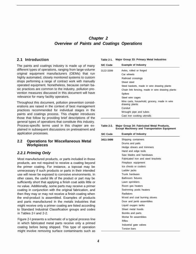
Major Group 33: Primary Metal Industries. . . . . . . . . . . . . . . . . . . . . . . . . . . . . . . . . . . . . . . . . . . . . . . . . . . 4
Major Group 34: Fabricated Metal Products, Except Machinery and Transportation Equipment. . . . . . . . . 4
Major Group 35: Industrial and Commercial Machinery and Computer Equipment . . . . . . . . . . . . . . . . . . . 6
Major Group 36: Electronics and Other Electrical Equipment and Components, ExceptComputerEquipment . . . . . . . . . . . . . . . . . . . . . . . . . . . . . . . . . . . . . . . . . . . . . . . . . . . . . . . . . . . . . . . . . . . 6
Major Group 37: Transportation Equipment . . . . . . . . . . . . . . . . . . . . . . . . . . . . . . . . . . . . . . . . . . . . . . . . . 6
Major Group 38: Measuring, Analyzing, and Controlling Instruments; Photographic, Medical,and Optical Goods; Watches and Clocks . . . . . . . . . . . . . . . . . . . . . . . . . . . . . . . . . . . . . . . . . . . . . . . . . . . 6
Major Group 39: Miscellaneous Manufacturing Industries . . . . . . . . . . . . . . . . . . . . . . . . . . . . . . . . . . . . . . 7
Typical Coating Technologies for Miscellaneous Metals Parts . . . . . . . . . . . . . . . . . . . . . . . . . . . . . . . . . . . 9
Most Common Manual Spray Guns . . . . . . . . . . . . . . . . . . . . . . . . . . . . . . . . . . . . . . . . . . . . . . . . . . . . . . . 9
Most Common Automated Coating Processes . . . . . . . . . . . . . . . . . . . . . . . . . . . . . . . . . . . . . . . . . . . . . . . 9
Common Spray Booth Designs. . . . . . . . . . . . . . . . . . . . . . . . . . . . . . . . . . . . . . . . . . . . . . . . . . . . . . . . . . 10
Typical Abatement Control Devices for Painting Facilities . . . . . . . . . . . . . . . . . . . . . . . . . . . . . . . . . . . . . 10
Electromotive Force Series . . . . . . . . . . . . . . . . . . . . . . . . . . . . . . . . . . . . . . . . . . . . . . . . . . . . . . . . . . . . . 17
Approximate Surface Tension of Substances in Contact With Their Vapor . . . . . . . . . . . . . . . . . . . . . . . . 19
Approximate Surface Tension of Metallic Elements in Inert Gas . . . . . . . . . . . . . . . . . . . . . . . . . . . . . . . . 19
Surface Tensions of Coating Ingredients Versus Plastic Substrates. . . . . . . . . . . . . . . . . . . . . . . . . . . . . . 22
Decision-Making Criteria Regarding Vendor-Supplied Materials . . . . . . . . . . . . . . . . . . . . . . . . . . . . . . . . 23
Decision-Making Criteria Regarding Surface Degreasing Process Efficiency and Alternatives toConventional Solvent-Based Methods . . . . . . . . . . . . . . . . . . . . . . . . . . . . . . . . . . . . . . . . . . . . . . . . . . . .27
Relative Boiling Points of Principal Degreasing Solvents. . . . . . . . . . . . . . . . . . . . . . . . . . . . . . . . . . . . . . 31
Typical Organic Solvents Used in Degreasing Operations. . . . . . . . . . . . . . . . . . . . . . . . . . . . . . . . . . . . . 33
Considerations for Aqueous Degreasing. . . . . . . . . . . . . . . . . . . . . . . . . . . . . . . . . . . . . . . . . . . . . . . . . . . 35
Selected Aqueous Degreasers . . . . . . . . . . . . . . . . . . . . . . . . . . . . . . . . . . . . . . . . . . . . . . . . . . . . . . . . . . 3 5
Typical Organic Constituents in Semi-aqueous Degreasers. . . . . . . . . . . . . . . . . . . . . . . . . . . . . . . . . . . . 38
Decision-Making Criteria Regarding Phosphating of Metal Surfaces . . . . . . . . . . . . . . . . . . . . . . . . . . . . . 42
Typical Spray Phosphating Production Rates in the Appliance Industry. . . . . . . . . . . . . . . . . . . . . . . . . . . 44
Process Line for Pretreatment of Complex Workpieces in Electrocoating Operation. . . . . . . . . . . . . . . . . 47
Process Line for Pretreatment of Simple Workpieces in Electrocoating Operation . . . . . . . . . . . . . . . . . . 47
Corrosion Resistance of Zinc Phosphate Coatings on Steel and Electrogalvanized Steel . . . . . . . . . . . . 48
Pretreatment Standards for Existing Sources That Electroplate Common Metals and Discharge38,000 Liters or More of Wastewater per Day. . . . . . . . . . . . . . . . . . . . . . . . . . . . . . . . . . . . . . . . . . . . . . .49
Pretreatment Standards for Existing Sources Involved in Metal Finishing Operations. . . . . . . . . . . . . . . . 49
Decision-Making Criteria Regarding Rinsing Processes. . . . . . . . . . . . . . . . . . . . . . . . . . . . . . . . . . . . . . . 54
Counter-Flow Rates for Workpieces With a 1 gal/min Drag-In. . . . . . . . . . . . . . . . . . . . . . . . . . . . . . . . . . 59
xvi

7-3
7-4
7-5
8-l
8-2
8-3
8-4
8-5
8-6
8-7
9-l
9-2
9-3
10-l
10-2
10-3
10-4
10-5
10-6
10-7
10-8
11-1
12-1
13-1
13-2
14-1
15-1
15-2
15-3
15-4
C-l
C-2C-3C-4
Tables (continued)
Page
Total Percentage Reduction in Flow Rate From One Rinse Tank to the Next for Workpieces Withal gal/min Drag-In . . . . . . . . . . . . . . . . . . . . . . . . . . . . . . . . . . . . . . . . . . . . . . . . . . . . . . . . . . . . . . . . . . . 59
Counter-Flow Rates for Workpieces With a 2 gal/min Drag-In. . . . . . . . . . . . . . . . . . . . . . . . . . . . . . . . . . 59
Counter-Flow Rates for Workpieces With a 0.5 gal/min Drag-In . . . . . . . . . . . . . . . . . . . . . . . . . . . . . . . . 59
Decision-Making Criteria Regarding Abrasive Blasting Processes. . . . . . . . . . . . . . . . . . . . . . . . . . . . . . . 64
Recycle Frequency of Abrasives . . . . . . . . . . . . . . . . . . . . . . . . . . . . . . . . . . . . . . . . . . . . . . . . . . . . . . . . 65
Selected Screen Sizes . . . . . . . . . . . . . . . . . . . . . . . . . . . . . . . . . . . . . . . . . . . . . . . . . . . . . . . . . . . . . . . . 6 6
Guide for Selected Abrasive Media. . . . . . . . . . . . . . . . . . . . . . . . . . . . . . . . . . . . . . . . . . . . . . . . . . . . . . . 68
Sample Specification Sheet for Steel Shot) . . . . . . . . . . . . . . . . . . . . . . . . . . . . . . . . . . . . . . . . . . . . . . . .68
Sample Specification Sheet for Steel Grit . . . . . . . . . . . . . . . . . . . . . . . . . . . . . . . . . . . . . . . . . . . . . . . . . 69
Comparison of Designations for Blast Cleaning Finishes. . . . . . . . . . . . . . . . . . . . . . . . . . . . . . . . . . . . . . 69
Decision-Making Criteria Regarding Transfer Efficiency. . . . . . . . . . . . . . . . . . . . . . . . . . . . . . . . . . . . . . . 75
Effect of Transfer Efficiency on VOC Emissions . . . . . . . . . . . . . . . . . . . . . . . . . . . . . . . . . . . . . . . . . . . . . 76
Annual Cost Savings Due to Transfer Efficiency (TE) Improvement From 30% to 45% . . . . . . . . . . . . . . 77
Decision-Making Criteria Regarding Liquid Compliant Coatings. . . . . . . . . . . . . . . . . . . . . . . . . . . . . . . . . 87
Advantages of Liquid Over Powder Coatings . . . . . . . . . . . . . . . . . . . . . . . . . . . . . . . . . . . . . . . . . . . . . . . 87
Advantages of Powder Over Liquid Coatings . . . . . . . . . . . . . . . . . . . . . . . . . . . . . . . . . . . . . . . . . . . . . . . 88
Advantages of Water-Borne Over High Solids Solvent-Borne Coatings. . . . . . . . . . . . . . . . . . . . . . . . . . . 91
Advantages of High Solids Solvent-Borne Coatings Over Water-Borne Coatings . . . . . . . . . . . . . . . . . . . 92
Air/Force Dry Versus Bake . . . . . . . . . . . . . . . . . . . . . . . . . . . . . . . . . . . . . . . . . . . . . . . . . . . . . . . . . . . . . 93
Typical RACT Limits for Miscellaneous Metal Parts Coatings . . . . . . . . . . . . . . . . . . . . . . . . . . . . . . . . . . 93
Single-Component Versus Plural-Component Coatings . . . . . . . . . . . . . . . . . . . . . . . . . . . . . . . . . . . . . . . 94
Decision-Making Criteria Regarding Powder Coating. . . . . . . . . . . . . . . . . . . . . . . . . . . . . . . . . . . . . . . . 115
ZahnCupOrificeSizes . . . . . . . . . . . . . . . . . . . . . . . . . . . . . . . . . . . . . . . . . . . . . . . . . . . . . . . . . . . . . .123
Decision-Making Criteria Regarding Minimizing Solvent Usage for Equipment Clean-Up. . . . . . . . . . . . 135
High-Boiling Solvents. . . . . . . . . . . . . . . . . . . . . . . . . . . . . . . . . . . . . . . . . . . . . . . . . . . . . . . . . . . . . . . . . 136
Decision-Making Criteria Regarding Paint Stripping Operations. . . . . . . . . . . . . . . . . . . . . . . . . . . . . . . . 140
Decision-Making Criteria Regarding Minimizing Pollution in Spray Booths . . . . . . . . . . . . . . . . . . . . . . . 148
Efficiency and Holding Capacity of Dry Filters . . . . . . . . . . . . . . . . . . . . . . . . . . . . . . . . . . . . . . . . . . . . . 154
Cost of Waste With 65 Percent Transfer Efficiency. . . . . . . . . . . . . . . . . . . . . . . . . . . . . . . . . . . . . . . . . . 154
Cost of Waste With 30 Percent Transfer Efficiency. . . . . . . . . . . . . . . . . . . . . . . . . . . . . . . . . . . . . . . . . . 155
T a b l e o f A s s u m p t i o n s . . . . . . . . . . . . . . . . . . . . . . . . . . . . . . . . . . . . . . . . . . . . . . . . . . . . . . . . . . . . . . . . . . 1 8 0
Calculation of Costs (TE = 30%). . . . . . . . . . . . . . . . . . . . . . . . . . . . . . . . . . . . . . . . . . . . . . . . . . . . . . . . 180
Calculation of Costs (TE = 45%). . . . . . . . . . . . . . . . . . . . . . . . . . . . . . . . . . . . . . . . . . . . . . . . . . . . . . . . 181
Formulas Used To Perform Calculations. . . . . . . . . . . . . . . . . . . . . . . . . . . . . . . . . . . . . . . . . . . . . . . . . . 181
xvii

Conversion Factors
Units of measurement used throughout this document can be converted to SI units using thefollowing conversion factors:
To convert. . . to . . . multiply by. . .
cubic feet
degrees Fahrenheit
feet
inches
quarts, liquid
pounds
pounds per cubic foot
pounds per cubic foot
pints, liquid
square inches
tons
U.S. gallons
cubic meters
degrees Celsius
meters
centimeters
to liters
kilograms
kilograms per cubic meter
kiloPascals
to liters
square inches
metric tons
liters
2.831685 x l0-2
toC = (toF - 32)/1.8
0.3048
2.54
0.946352946
0.45354237
16.0184634
6.895
0.473176473
6.4516
0.90718474
3.785
XVIII
Acknowledgments
Doug Williams of EPA’s Off ice of Research and Development, Center for Environmental ResearchInformation, was responsible for the development and review of this document. Ron Joseph, ofRon Joseph and Associates, Inc., Saratoga, California, served as the document’s author under aconsulting agreement with Eastern Research Group, Inc. (ERG), of Lexington, Massachusetts. JeffCantin was ERG’s project manager for the task. ERG also edited the document and prepared it forpublication.
xix

Section 1Overview
1
Chapter 1Introduction
1.1 Pollution Prevention in the Paintsand Coatings Industry
Given the wide use of solvent-based process materialsand the extensive amounts of wastewater generated bypaints and coatings operations, this industry representsa significant source of multimedia pollution. This manualpresents recommended practices for minimizing thegeneration of pollution in paints and coatings operations.
Many facility operators are actively investigating the useof alternative cleaning formulations and paint systems,such as aqueous degreasers and powder coatings, inan effort to reduce toxic air emissions and control costsassociated with the treatment of contaminated effluent.These efforts are being driven in part by regulations atthe federal, state, and local level aimed at preventingpollution at its source. In particular, the paints and coat-ings and other industries must achieve compliance withthe Clean Air Act and amendments. Along with prevent-ing pollution at its source, companies are increasinglyencouraged to limit the generation of waste throughrecycling and enhanced management practices.
Because of the diversity in the types of paints andcoatings operations, many operators of small and mid-sized facilities have few opportunities to take advantageof technology transfer within the industry. The informa-tion in this manual should help operators to perform acomplete investigation of pollution prevention (i.e., P2as referred to by government and industry) factors intheir processes and to consider using “cleaner” tech-nologies and more efficient management practices.
Additionally, this manual presents numerous sugges-tions concerning management practices that may ap-pear to have no direct connection with pollutionprevention. Nonetheless, many operators in this indus-try have found that by making improvements in thename of quality and efficiency, additional benefits canbe realized in terms of reduced waste.
The manual covers all basic aspects of a paints andcoatings operation. Pollution prevention strategies dis-cussed lead both directly and indirectly to waste minimi-zation. The majority of these strategies can beimplemented without the need for major capital expen-
ditures. Often by modifying the approach to a conven-tional practice, considerable waste and cost reductionbenefits can be realized.
1.2 The Audience for This Document
As presented, the suggestions in this document aredirected primarily to facility operators and managers,regardless of whether their paints and coatings proc-esses are conducted on an intermittent or continuousbasis. Nonetheless, the material also is intended formanufacturing process managers, environmental engi-neers, and painters themselves. Operators of small andmedium-sized facilities likely will have the most to gainby implementing recommendations presented in thisdocument, particularly facilities that do not have a full-time paints and coatings process engineer on staff. Mostlarge operations, such as original equipment manufac-turers with in-house expertise, already will have systemsin place that incorporate most of these strategies. Al-though many aspects of paints and coatings processesare chemical specific, the vast majority of informationpresented in this document can be understood andacted upon regardless of whether the reader has ascience background.
1.3 The Organization of This Document
This manual is divided into four sections. This first sec-tion provides a general introduction to pollution preven-tion in relation to paints and coatings operations alongwith an overview of the industry (Chapter 2). The sec-tions that follow address pollution prevention considera-tions in the context of the basic process flow for paintsand coatings operations. Thus, the discussion proceedsfrom pretreatment stages, such as degreasing andphosphating, to the various methods of paint applica-tion. The final section presents a selection of case stud-ies that emphasize approaches for reducing processwaste.
Section Two on pretreatment factors begins with a gen-eral discussion about the importance of proper adhesionof the coating to the substrate for minimizing pollution inpaints and coatings operations (Chapter 3). The chapterintroduces the concept of “right-first-time” processing as
2
a management practice that focuses on avoiding re-works of coatings that fail because the workpiece wasinadequately prepared to receive a paint system. Asdescribed in Chapter 4, a comprehensive approach toensuring proper adhesion of applied coatings beginswith the appropriate handling and storage of raw mate-rials and vendor-supplied component parts.
Chapters 5, 6, and 7 address pollution prevention inregard to the fundamental pretreatment processes ofdegreasing, phosphating, and rinsing, respectively. Formany operations, conventional approaches to cleaningand otherwise preparing workpiece surfaces for coatingapplication generate large amounts of wastewater,much of which must be handled expensively as hazard-ous waste. These chapters suggest alternative ap-proaches to performing these pretreatment steps thatcan, for instance, minimize water usage (i.e., by usingcounter-flow rinsing) and reduce the use of toxic, sol-vent-based materials (e.g., by using aqueous de-greasers). Although degreasing, phosphating, and rinsingoften are conducted in an integrated process line, theyare addressed separately in this document as a meansof highlighting specific best management practices.
The final pretreatment chapter (Chapter 8) addressespollution prevention in regard to abrasive blast cleaning.A primary consideration is the recyclability of the abra-sive media; however, water-use reduction as an inciden-tal benefit of blasting also is addressed.
Section Three on application process factors beginswith a discussion of transfer efficiency-of the coatingto the workpiece substrate-as a fundamental consid-eration for pollution prevention (Chapter 9). Of the manystrategies recommended in this manual, transfer effi-ciency improvement is likely to yield the greatest pollu-tion and process cost reductions. Several of thepractices discussed can be implemented immediately,without the need for either capital expenditure-or proc-ess-line reconfiguration.
Chapters 10 and 11 focus on the two types of coatingsystems, liquid compliant and powder coatings, respec-tively, in terms of selection criteria related to pollutionprevention. The discussion on liquid coatings, for exam-ple, presents a basis for considering the use of coatingsthat are low in volatile organic compounds (VOCs),while the powder coatings discussion considers appro-priate situations for the use of these low-pollutant-gen-erating systems.
Although the pollution prevention benefits of controllingthe viscosity of an applied coating are somewhat indi-rect, the management practices suggested in Chapter12 can be essential for ensuring right-first-time process-ing. As this chapter explains, by altering the viscosity ofa coating to achieve better substrate coverage for par-ticular workpieces, superior finishes can be achieved,thus minimizing the need for reworks. Several strategiesare suggested for maintaining a constant viscositythroughout the application process to improve the con-sistency of color, gloss, and texture in a coating system.
Chapters 13, 14, and 15 speak to practices that can havea more direct effect on pollution prevention. For exam-ple, recommended practices include minimizing solventusage when cleaning equipment (e.g., through recyclingcleaning formulations) and minimizing pollution in spraybooths (e.g., by controlling particulate emissions).
Section Four provides case studies that illustrate ap-proaches to addressing typical paints and coating prob-lems (Chapter 16).
Appendixes to the document provide a list of suppliersof aqueous and semi-aqueous degreasers and equip-ment (Appendix A), a methodology for calculating therinsing flow rate required to achieve a specified dilutionratio (Appendix B), and a spreadsheet for factoringtransfer efficiency considerations into a coating applica-tion process (Appendix C).
Chapter 2Overview of Paints and Coatings Operations
2.1 Introduction
The paints and coatings industry is made up of manydifferent types of operations, ranging from large-volumeoriginal equipment manufacturers (OEMs) that runhighly automated, closely monitored systems to customshops performing a range of contract work with manuallyoperated equipment. Nonetheless, because certain ba-sic practices are common to the industry, pollution pre-vention measures discussed in this document will haverelevance for many facility operators.
Throughout this document, pollution prevention consid-erations are raised in the context of best managementpractices recommended for individual stages in thepaints and coatings process. This chapter introducesthose that follow by providing brief descriptions of thegeneral types of operations that constitute this industry.Process-specific terms used in this chapter are ex-plained in subsequent discussions on pretreatment andapplication processes.
2.2 Operations for Miscellaneous MetalWorkpieces
2.2.1 Priming Only
Most manufactured products, or parts included in thoseproducts, are not required to receive a coating beyondthe primer coating. For instance, a topcoat may beunnecessary if such products or parts in their intendeduse will never be exposed to corrosive environments. Inother cases, the useful life of the product or part may besufficiently short that applying a finish coat adds little orno value. Additionally, some parts may receive a primercoating in conjunction with the original fabrication, andthen they may or may not receive a finish coating whenthe end-product is assembled. Examples of productsand parts manufactured in the metals industries thatmight receive only a primer coating are listed accordingto Standard Industrial Classification groups and codesin Tables 2-l and 2-2.
Figure 2-l presents a schematic of a typical process linein which fabricated metal parts receive only a primedcoating before being shipped. This type of operationmight involve removing surface contaminants such as
Table 2-1. Major Group 33: Primary Metal Industries
SIC Code Example of Industry
3122-3399 Axles, rolled or forged
Car wheels
Railroad crossings
Sheet steel
Steel baskets, made in wire drawing plants
Chain link fencing, made in wire drawing plants
Spikes
Steel wire cages
Wire carts, household, grocery, made in wiredrawing plants
Conduit
Wrought pipe and tubes
Cast iron cooking utensils
Table 2-2. Major Group 34: Fabricated Metal Products,Except Machinery and Transportation Equipment
SIC Code
3411-3499
Example of Industry
Shipping containers
Drums and pails
Hedge shears and trimmers
Hand and edge tools
Saw blades and handsaws
Fabricated iron and steel brackets
Fireplace equipment
Ice chests or coolers
Ladder jacks
Trunk hardware
Bathroom fixtures
Lawn sprinklers
Room gas heaters
Swimming pools heaters
Radiators
Wood and coal burning stoves
Door and jamb assemblies
Liquid oxygen tanks
Sheet metal hoods
Bombs and parts
Mortar fin assemblies
Rifles
Industrial gate valves
Torsion bars
4
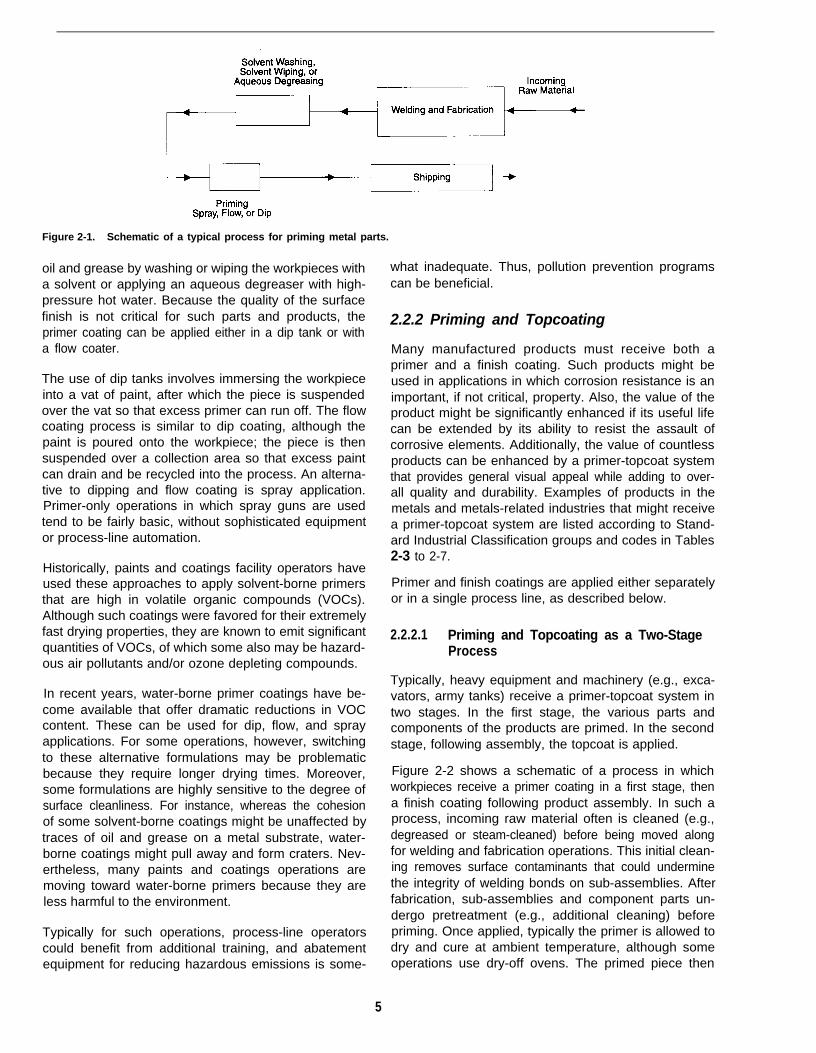
Figure 2-1. Schematic of a typical process for priming metal parts.
oil and grease by washing or wiping the workpieces witha solvent or applying an aqueous degreaser with high-pressure hot water. Because the quality of the surfacefinish is not critical for such parts and products, theprimer coating can be applied either in a dip tank or witha flow coater.
The use of dip tanks involves immersing the workpieceinto a vat of paint, after which the piece is suspendedover the vat so that excess primer can run off. The flowcoating process is similar to dip coating, although thepaint is poured onto the workpiece; the piece is thensuspended over a collection area so that excess paintcan drain and be recycled into the process. An alterna-tive to dipping and flow coating is spray application.Primer-only operations in which spray guns are usedtend to be fairly basic, without sophisticated equipmentor process-line automation.
Historically, paints and coatings facility operators haveused these approaches to apply solvent-borne primersthat are high in volatile organic compounds (VOCs).Although such coatings were favored for their extremelyfast drying properties, they are known to emit significantquantities of VOCs, of which some also may be hazard-ous air pollutants and/or ozone depleting compounds.
In recent years, water-borne primer coatings have be-come available that offer dramatic reductions in VOCcontent. These can be used for dip, flow, and sprayapplications. For some operations, however, switchingto these alternative formulations may be problematicbecause they require longer drying times. Moreover,some formulations are highly sensitive to the degree ofsurface cleanliness. For instance, whereas the cohesionof some solvent-borne coatings might be unaffected bytraces of oil and grease on a metal substrate, water-borne coatings might pull away and form craters. Nev-ertheless, many paints and coatings operations aremoving toward water-borne primers because they areless harmful to the environment.
Typically for such operations, process-line operatorscould benefit from additional training, and abatementequipment for reducing hazardous emissions is some-
what inadequate. Thus, pollution prevention programscan be beneficial.
2.2.2 Priming and Topcoating
Many manufactured products must receive both aprimer and a finish coating. Such products might beused in applications in which corrosion resistance is animportant, if not critical, property. Also, the value of theproduct might be significantly enhanced if its useful lifecan be extended by its ability to resist the assault ofcorrosive elements. Additionally, the value of countlessproducts can be enhanced by a primer-topcoat systemthat provides general visual appeal while adding to over-all quality and durability. Examples of products in themetals and metals-related industries that might receivea primer-topcoat system are listed according to Stand-ard Industrial Classification groups and codes in Tables2-3 to 2-7.
Primer and finish coatings are applied either separatelyor in a single process line, as described below.
2.2.2.1 Priming and Topcoating as a Two-StageProcess
Typically, heavy equipment and machinery (e.g., exca-vators, army tanks) receive a primer-topcoat system intwo stages. In the first stage, the various parts andcomponents of the products are primed. In the secondstage, following assembly, the topcoat is applied.
Figure 2-2 shows a schematic of a process in whichworkpieces receive a primer coating in a first stage, thena finish coating following product assembly. In such aprocess, incoming raw material often is cleaned (e.g.,degreased or steam-cleaned) before being moved alongfor welding and fabrication operations. This initial clean-ing removes surface contaminants that could underminethe integrity of welding bonds on sub-assemblies. Afterfabrication, sub-assemblies and component parts un-dergo pretreatment (e.g., additional cleaning) beforepriming. Once applied, typically the primer is allowed todry and cure at ambient temperature, although someoperations use dry-off ovens. The primed piece then
5

Table 2-3. Major Group 35: Industrial and CommercialMachinery and Computer Equipment
SIC Code
3511-3599
Example of Industry
Windmills for generating power
Steam engines, except locomotives
Engine and engine parts
Marine engines
Agricultural implements and machinery
Blowers and cutters
Farm elevators
Greens mowing equipment
Combines (harvesters and threshers)
Spraying machines
Construction cranes
Road graders
Logging equipment
Tractors
Vibrators for concrete construction
Mining machinery and equipment
Elevators and moving stairways
Conveyors and conveying equipment
Machine tools
Power-driven hand tools
Textile machinery
Woodworking machinery
Printing trade machinery
Table 2-4. Major Group 36: Electronics and Other ElectricalEquipment and Components, Except ComputerEquipment
SIC Code
3612-3699
Example of Industry
Power distribution and specialty transformers
Switchgear and switchboard apparatus
Motors and generators
Relays and industrial controls
Battery chargers
Barbecues, grills, and braziers
Electric dehumidifiers
Household fans
Electric wall heaters
Vacuum cleaners
Floor waxers and polishers
Electric wiring boxes
Electric conduits and fittings
Residential electric lighting fixtures
Commercial, industrial, andinstitutional lighting fixtures
Household audio and video equipment
may be stored for a time as inventory before it is usedin end-product assembly.
The component parts of an end-product can becomescuffed and soiled during assembly and product testingoperations. In many cases, the product becomes suffi-ciently marred and soiled that it must undergo some
Table 2-5. Major Group 37: Transportation Equipment
SIC Code Example of Industry
3712-3799 Ambulances
Car bodies
6
Fire department vehicles
Motor homes
Personnel carriers
Tractors
Motor vehicle parts and accessories
Oil, air, and fuel filters
Motor vehicle horns
Exhaust mufflers
Motor vehicle radiators
Patrol boats
Floating radar towers
Steam engines (locomotives)
Trolley buses
Bicycles and parts
Motor scooters and parts
Campers for mounting on trucks
Military tanks
Trailer hitches
Wheel barrows
Table 2-6. Major Group 38: Measuring, Analyzing, andControlling Instruments; Photographic, Medical,and Optical Goods; Watches and Clocks
SIC Code
3812-3873
Example of Industry
Air traffic control radar systems
Distance measuring equipment
Gyroscopes
Hydrophones
Nautical instruments
Laboratory balances
Laboratory hot plates
Laboratory furniture
Clothes dryer controls
Thermostats
Computer interface equipment
Differential pressure instruments
Magnetic flow meters
Speedometers
Sparkplug testing equipment
X-ray equipment
Photographic developing machines
Photographic enlargers
Appliance timers
surface preparation (e.g., selective scuff sanding, sol-vent wiping, hot-water spray) before the finish coating isapplied. On occasion, surfaces may have become suf-ficiently damaged overall that the assembled productmust be prepped and reprimed either extensively or inselected areas.

Factors that can contribute to the need for remedialpreparation before applying a topcoat, unnecessarilygenerating pollution and adding to costs, include:
l Inadequate initial surface preparation.
l Use of a low-quality primer.
Table 2-7. Major Group 39: Miscellaneous ManufacturingIndustries
SIC Code
3911-3999 Electronic musical instruments
Music stands
Games, toys
Fish and bait buckets
Exercising machines
Rowing machines
Treadmills
Pen holders and parts
Artist frames
Easels
Stamp pads
Hand stamps (e.g., time, date)
Costume jewelry
Costume ornaments
Paint rollers
Street sweeping brooms
Advertising displays
Name plates
Neon signs
l Inadequate storage procedures (e.g., outdoors anduncovered).
l Improper material handling procedures.
As with the primer coating, following topcoat applicationthe finished product is dried either at ambient tempera-ture or in a dry-off oven.
2.2.2.2 Priming and Topcoating as a Single-StageProcess
For smaller products that require little or no assemblybefore shipping (e.g., wheel barrows, music stands) andfor some component parts, a primer-topcoat system isapplied in a single process line. Such a process issimilar to the two-stage process, except that the paintingoperation is not interrupted for assembly.
Figure 2-3 shows a schematic of a process in whichworkpieces receive a primer coating and a finish coatingin a single-stage operation. Typically, for such a processthe entire operation is conveyorized, from cleaning theincoming raw materials to applying the topcoat. Afterdrying and curing, the workpiece is removed from theconveyor and prepared for shipping or stored for assem-bly operations.
2.2.3 Surface Preparation
The amount of surface preparation included in paintsand coatings operations for miscellaneous metal work-
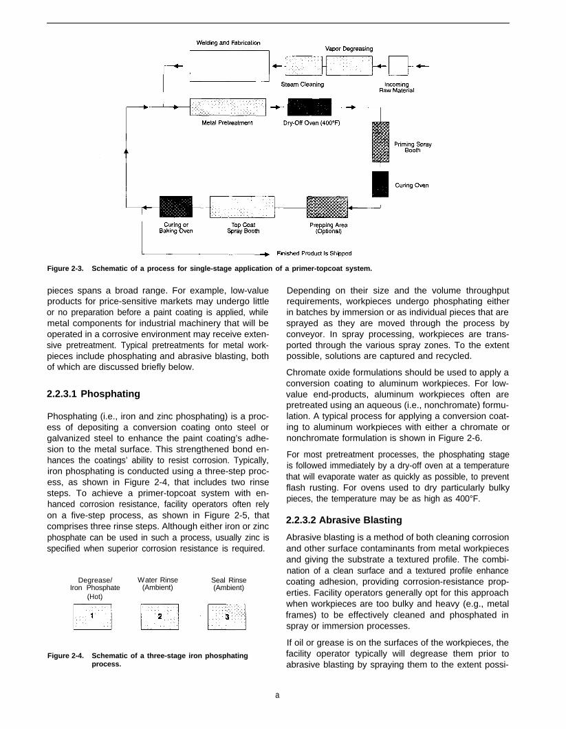
Figure 2-3. Schematic of a process for single-stage application of a primer-topcoat system.
pieces spans a broad range. For example, low-valueproducts for price-sensitive markets may undergo littleor no preparation before a paint coating is applied, whilemetal components for industrial machinery that will beoperated in a corrosive environment may receive exten-sive pretreatment. Typical pretreatments for metal work-pieces include phosphating and abrasive blasting, bothof which are discussed briefly below.
2.2.3.1 Phosphating
Phosphating (i.e., iron and zinc phosphating) is a proc-ess of depositing a conversion coating onto steel orgalvanized steel to enhance the paint coating’s adhe-sion to the metal surface. This strengthened bond en-hances the coatings’ ability to resist corrosion. Typically,iron phosphating is conducted using a three-step proc-ess, as shown in Figure 2-4, that includes two rinsesteps. To achieve a primer-topcoat system with en-hanced corrosion resistance, facility operators often relyon a five-step process, as shown in Figure 2-5, thatcomprises three rinse steps. Although either iron or zincphosphate can be used in such a process, usually zinc isspecified when superior corrosion resistance is required.
Degrease/Iron Phosphate
(Hot)
Water Rinse(Ambient)
Seal Rinse(Ambient)
Figure 2-4. Schematic of a three-stage iron phosphatingprocess.
Depending on their size and the volume throughputrequirements, workpieces undergo phosphating eitherin batches by immersion or as individual pieces that aresprayed as they are moved through the process byconveyor. In spray processing, workpieces are trans-ported through the various spray zones. To the extentpossible, solutions are captured and recycled.
Chromate oxide formulations should be used to apply aconversion coating to aluminum workpieces. For low-value end-products, aluminum workpieces often arepretreated using an aqueous (i.e., nonchromate) formu-lation. A typical process for applying a conversion coat-ing to aluminum workpieces with either a chromate ornonchromate formulation is shown in Figure 2-6.
For most pretreatment processes, the phosphating stageis followed immediately by a dry-off oven at a temperaturethat will evaporate water as quickly as possible, to preventflash rusting. For ovens used to dry particularly bulkypieces, the temperature may be as high as 400°F.
2.2.3.2 Abrasive Blasting
Abrasive blasting is a method of both cleaning corrosionand other surface contaminants from metal workpiecesand giving the substrate a textured profile. The combi-nation of a clean surface and a textured profile enhancecoating adhesion, providing corrosion-resistance prop-erties. Facility operators generally opt for this approachwhen workpieces are too bulky and heavy (e.g., metalframes) to be effectively cleaned and phosphated inspray or immersion processes.
If oil or grease is on the surfaces of the workpieces, thefacility operator typically will degrease them prior toabrasive blasting by spraying them to the extent possi-
a

Water Rinse(Ambient)
Iron or ZincPhosphate
(Hot)
Water Rinse(Ambient)
Seal Rinse(Ambient)
Figure 2-5. Schematic of a five-stage iron or zinc phosphating process.
Water Rinse(Ambient)
Deoxidize(120°F)
Chromate orNonchromate
Water Rinse Conversion Water Rinse Seal Rinse(Ambient) Coating (Ambient) (Ambient)
Figure 2-6. Schematic of a typical conversion coating process for aluminum workpieces.
ble with super-heated steam or high-pressure hot water. spray booth designs are listed in Table 2-11. SprayThis minimizes the likelihood that the blasting media will booths in these designs are available off-the-shelf or astransfer contaminants between workpieces. custom equipment.
2.2.4 Application of Paint Coating Systems
The types of paint coatings and application systemsused in paints and coatings operations for miscellane-ous metal workpieces also span a broad range. A se-lected list of paint coatings that includes both water- andsolvent-borne systems is presented in Table 2-8. Typicalspray and automated applications equipment is listed inTables 2-9 and 2-10, respectively. Because many paintsand coatings operations use spray application, common
2.2.5 Abatement Equipment
Although emission abatement devices are not widelyused in operations applying coatings to miscellaneousmetal products, several types of equipment are avail-able. Typical devices are listed in Table 2-12. Indeed,
Table 2-8. Typical Coating Technologies for MiscellaneousMetals Parts
Table 2-9. Most Common Manual Spray Guns
Conventional air atomizing
Air-assisted airless
Airless
Classification
Water borne (air orforce dry)
Water borne (bake)
Solvent borne (air orforce dry)
Solvent borne (bake)
Specialized coatings
Resin Technology
Alkyd and modified alkyd (waterbased)
Acrylic latex
Epoxy (water based)
Alkyd and modified alkyd (waterbased)
Acrylics
Alkyd and modified alkyd
Epoxy catalyzed (two component)
Polyurethane (single or twocomponent)
Alkyds and modified alkyds
Acrylics
Polyester (oil free)
Autodeposited
Electrodeposited
Powder
Ultraviolet curable
High volume, low pressure (HVLP)
Electrostatic (low voltage)
Conventional air atomizing
Air-assisted airless
Airless
HVLP
Electrostatic powder application
Table 2-10. Most Common Automated Coating Processes
Dip coating
Flow coating
Electrodeposition
Autodeposition (primarily for priming steel)
Electrostatic turbo bells and discs
Automatic spray gunsa
a Using any of the delivery and atomization mechanisms listed inTable 2-9, except that electrostatic guns will usually be of the high-voltage type.
9
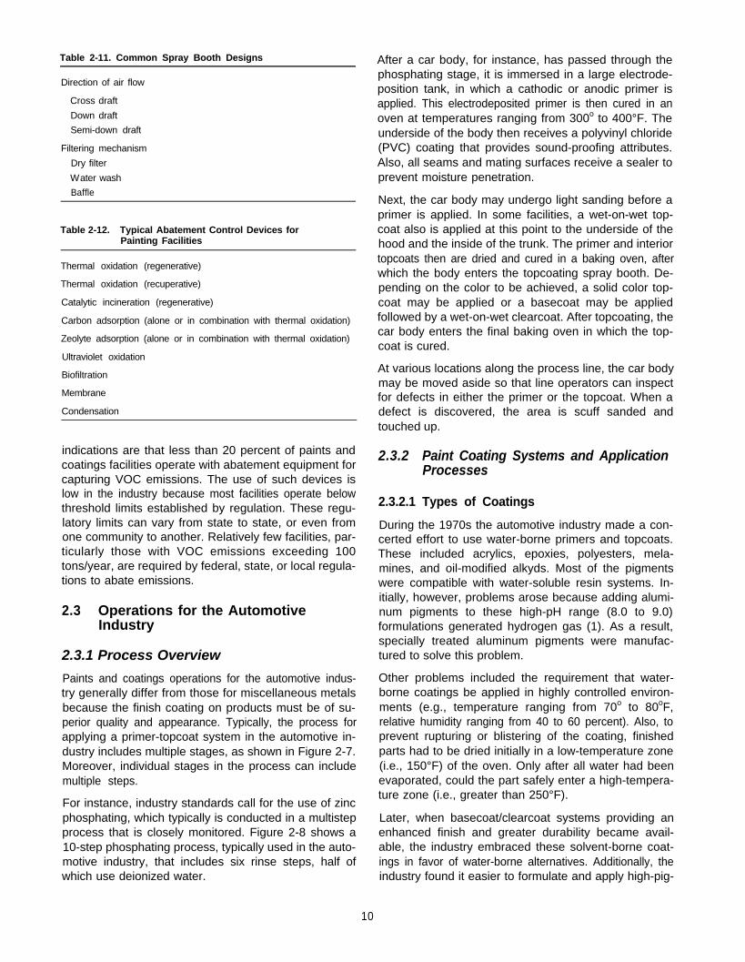
Table 2-11. Common Spray Booth Designs
Direction of air flow
Cross draft
Down draft
Semi-down draft
Filtering mechanism
Dry filter
Water wash
Baffle
Table 2-12. Typical Abatement Control Devices forPainting Facilities
Thermal oxidation (regenerative)
Thermal oxidation (recuperative)
Catalytic incineration (regenerative)
Carbon adsorption (alone or in combination with thermal oxidation)
Zeolyte adsorption (alone or in combination with thermal oxidation)
Ultraviolet oxidation
Biofiltration
Membrane
Condensation
indications are that less than 20 percent of paints andcoatings facilities operate with abatement equipment forcapturing VOC emissions. The use of such devices islow in the industry because most facilities operate belowthreshold limits established by regulation. These regu-latory limits can vary from state to state, or even fromone community to another. Relatively few facilities, par-ticularly those with VOC emissions exceeding 100tons/year, are required by federal, state, or local regula-tions to abate emissions.
2.3 Operations for the AutomotiveIndustry
2.3.1 Process Overview
Paints and coatings operations for the automotive indus-try generally differ from those for miscellaneous metalsbecause the finish coating on products must be of su-perior quality and appearance. Typically, the process forapplying a primer-topcoat system in the automotive in-dustry includes multiple stages, as shown in Figure 2-7.Moreover, individual stages in the process can includemultiple steps.
For instance, industry standards call for the use of zincphosphating, which typically is conducted in a multistepprocess that is closely monitored. Figure 2-8 shows a10-step phosphating process, typically used in the auto-motive industry, that includes six rinse steps, half ofwhich use deionized water.
10
After a car body, for instance, has passed through thephosphating stage, it is immersed in a large electrode-position tank, in which a cathodic or anodic primer isapplied. This electrodeposited primer is then cured in anoven at temperatures ranging from 300o to 400°F. Theunderside of the body then receives a polyvinyl chloride(PVC) coating that provides sound-proofing attributes.Also, all seams and mating surfaces receive a sealer toprevent moisture penetration.
Next, the car body may undergo light sanding before aprimer is applied. In some facilities, a wet-on-wet top-coat also is applied at this point to the underside of thehood and the inside of the trunk. The primer and interiortopcoats then are dried and cured in a baking oven, afterwhich the body enters the topcoating spray booth. De-pending on the color to be achieved, a solid color top-coat may be applied or a basecoat may be appliedfollowed by a wet-on-wet clearcoat. After topcoating, thecar body enters the final baking oven in which the top-coat is cured.
At various locations along the process line, the car bodymay be moved aside so that line operators can inspectfor defects in either the primer or the topcoat. When adefect is discovered, the area is scuff sanded andtouched up.
2.3.2 Paint Coating Systems and ApplicationProcesses
2.3.2.1 Types of Coatings
During the 1970s the automotive industry made a con-certed effort to use water-borne primers and topcoats.These included acrylics, epoxies, polyesters, mela-mines, and oil-modified alkyds. Most of the pigmentswere compatible with water-soluble resin systems. In-itially, however, problems arose because adding alumi-num pigments to these high-pH range (8.0 to 9.0)formulations generated hydrogen gas (1). As a result,specially treated aluminum pigments were manufac-tured to solve this problem.
Other problems included the requirement that water-borne coatings be applied in highly controlled environ-ments (e.g., temperature ranging from 70o to 80oF,relative humidity ranging from 40 to 60 percent). Also, toprevent rupturing or blistering of the coating, finishedparts had to be dried initially in a low-temperature zone(i.e., 150°F) of the oven. Only after all water had beenevaporated, could the part safely enter a high-tempera-ture zone (i.e., greater than 250°F).
Later, when basecoat/clearcoat systems providing anenhanced finish and greater durability became avail-able, the industry embraced these solvent-borne coat-ings in favor of water-borne alternatives. Additionally, theindustry found it easier to formulate and apply high-pig-

Figure 2-7. Schematic of a typical process for applying a primer-topcoat system In the automotive industry.
Degrease Rinse DI Rinse Zinc Phosphate(Micro-crystalline)
Rinse
DI Rinse
Dry-Off Oven DI Mist Spray DI Rinse Chromate or Non-chromate Sealer
<
DI = deionized water
Figure 2-8. Schematic of a typical process for applying a zinc phosphate coating in the automotive industry.
ment-loaded basecoats, particularly those containingmetallic pigments, in solvent-borne systems.
The industry returned to water-borne basecoats in the1980s when improved formulations became available.Water-borne basecoats also are used extensively onautomotive plastics.
l
2.3.2.2 Coating Systems
Primer-topcoat systems for the automotive industry caninclude any of the following components:
l Primers: Most primers are applied by electrodeposi-tion and many are based on anodic or cathodic for-mulations, although cathodic epoxy is the most popular.
11
New electrodeposited primers tend to be low in VOCsand heavy metals and they yield good coverage andcorrosion resistance (2). Water-borne primer surfac-ers also are being tested by the industry.
Basecoats: Both conventional solvent-borne base-coats and the newer water-borne systems are acrylicmelamine formulations.
Clearcoats: These finish coatings are available inmany forms:
- Conventional solvent-borne acrylic melamine.
- New water-borne acrylic melamine.
- Two-component polyurethane.

- One-component polyurethane.
- Scratch-resistant clearcoats based on silanechemistry.
- Scratch-resistant clearcoats based on acid-epoxychemistry.
- Powder coatings.
l Monocoats: These coatings combine a basecoat anda clearcoat. Although most of them are solvent-borne,the industry is moving toward the water-borne base-coat/clearcoat systems.
These coatings are likely to gain greater popularity whenbaking temperatures can be reduced to the 250o to285°F range. In particular, the industry is becomingincreasingly interested in powder coatings (3).
2.3.2.3 Application Equipment
The automotive industry relies on sophisticated sprayapplication systems to achieve superior coatings. Facili-ties (e.g., OEMs) typically operate down-draft, wash-water systems that are totally enclosed to minimize dustgeneration and overspray. Most operations apply auto-motive coatings using both high-voltage, electrostaticturbo-bell systems and manual electrostatic or high vol-ume, low pressure (HVLP) spray guns. Generally, air-less or air-assisted airless spray guns are used on thefinishing line exclusively for the application of sealersand sound-proofing coatings.
2.3.3 Abatement Equipment
Given the importance of paints and coatings applicationin the automotive industry, pollution control equipmentis an important aspect of operations generally. Facilitiestypically use thermal oxidizers, catalytic incinerators,and carbon adsorbers, or a combination of these tech-nologies, to control hazardous emissions. Moreover, theindustry has pioneered the development of many low-emission coating systems. As a result of its prominencein the paints and coatings area, the automotive industryplays a leadership role in pollution prevention technolo-gies, and many of the approaches detailed in this docu-ment are based on these innovations.
2.4 Operations for Plastic Parts
2.4.1 Surface Preparation
Paints and coatings are applied to plastic parts andcomponents primarily for the automotive and elec-tronics industries (e.g., business machines). The mostnotable difference between plastic and metal work-pieces regarding paints and coatings operations is thatsurface preparation processes primarily rely on de-greasing. Plastic workpieces are not subjected tophosphating, although in some operations pieces are
scuff sanded to achieve a surface that will enhancecoating adhesion.
Most plastic workpieces must be subjected to degreas-ing operations to remove contaminants, such as moldrelease agents. Because the characteristics of plasticscan be quite varied, surface cleaning formulations mustbe carefully selected. For example, whereas some plas-tics are solvent sensitive, others are inert. Thus, whenselecting a degreaser the facility operator must considerboth the basic nature of the particular plastic material aswell as the method by which it was manufactured.
Typically, high-volume production operations degreaseplastic workpieces using a conveyorized spray washerprocess that includes rinsing with deionized water. Fewoperations clean plastic pieces with the vapor degreas-ing method. Regardless of the particular approach, theoperator must guard against the tendency of some plas-tics to take on an electrostatic charge that can attractdust and undermine coatings.
Plastics hold some advantage over metal workpieces interms of pollution prevention because phosphating isnever part of the paints and coatings process. The moredistinct advantage in this regard, however, is that be-cause plastics do not corrode as metal does, less paintneeds to be applied to the surface. Thus, the generationof pollutants is reduced.
2.4.2 Coatings Systems
The most widely used coating system for plastics istwo-component polyurethane, which provides superioradhesion and exhibits outstanding durability. Moreover,this type of system can be formulated for application onboth rigid and flexible plastics. In situations where theplastic in a workpiece is not compatible with polyure-thane, epoxy formulations present an alternative thatprovides good adhesion and excellent performancecharacteristics.
Because most plastics are heat sensitive, coatingsmust be air- or force-dried at relatively low temperatures(i.e., below 180°F). Thus, coating systems that mustbe baked on at temperatures above 25OoF, such asacrylics, melamines, and polyesters, generally cannotbe used on plastic workpieces.
2.4.3 Application Equipment
Coating systems are applied to plastic workpieces usingboth manual and automated spray gun systems. Facili-ties typically use conventional air-spray, air-assisted air-less, and HVLP spray guns. Electrostatic guns arepreferred when the plastic has been formulated to bemoderately conductive or if a conductive primer hasbeen applied.
12

Generally, requirements concerning the appearance offinished pieces cannot be met using airless spray guns.For similar reasons, dip or flow coatings are rarely usedon plastic surfaces.
The type of spray booth used in plastic coating opera-tions depends on the specifications for the finishedworkpieces.
2.4.4 Abatement Equipment
The use of emission abatement equipment for facilitiesapplying paints and coatings to plastic workpieces var-ies widely. In general, large operations with high VOC-emission rates often are required to add controlequipment, whereas smaller facilities with lower emis-sion rates may be allowed to exhaust VOCs into the airwithout abatement.
2.5 Custom Coating Operations
Because custom coating operations work on a contractbasis, the types of workpieces a particular facility proc-esses can vary widely. For instance, a custom shopmight shift coating operations from metal to plastic work-pieces within a short period. In general, such operationsare less sophisticated than the paints and coatings op-erations of OEMs and are capable of applying eitherliquid or powder coatings but not both. A very few cus-tom houses (primarily in the Midwest) have the facilitiesfor applying liquid, powder, and electrocoatings.
Typically, custom shops are required to use the coatingsspecified by the customer. In some locations, however,facility operators are encouraged by the stringency ofenvironmental regulations (e.g., in California) to usewater-borne materials when feasible.
Most custom shops apply paint exclusively with manu-ally operated spray guns. If an operation handles largequantities of throughput for individual contract jobs,however, it is likely to have an automated process.
The general trend among custom shops is awayfrom water-wash spray booths and toward dry-filterunits, which are less expensive and easier to maintain.Additionally, with dry-filter spray booths, the operatordoes not need to use chemicals to detackify the coatingoverspray; thus, disposal of the paint waste sludgeand contaminated water in the spray booth watertrough are eliminated. A few of the larger shops areequipped with drive-in spray booths, with either cross-or down-draft capabilities. Most, however, operate withthe cross-draft, walk-in type of booth, which can be threesided or totally enclosed.
In general, the volume of throughput at individual cus-tom coating shops is sufficiently low that facility opera-tors are not required to install emission abatementequipment. Exceptions are the few larger operations inthis industry sector.
2.6 ReferencesJamrog, R. 1993. Automotive water-borne coatings. Products Fin-ishing 93:56-62.
Bailey, J.M. 1992. Automotive coating trends. Industrial Finishing68:23-24.
Schrantz, J. 1993. Polyurethane automotive coatings. IndustrialFinishing 69:34-35.
7 Additional ReadingU.S. EPA. 1991. Report on compliance coatings for the miscellaneous
metal parts industry. Stationary Source Compliance Division.EPA/340/1-91/009.
13

Section 2Pretreatment Factors
15
Chapter 3Adhesion as a Critical Factor
3.1 Introduction
3.1.1 Pollution Prevention Considerations
Adhesion is a critical factor for ensuring the integrity ofa coating. Only if a firm bond is established with asubstrate can a coating provide the surface protectionrequired by its product application. Many factors, how-ever, can undermine the ability to thoroughly cover asurface. For metals and alloys, the principal threat togood adhesion is corrosion, which can result in degra-dation products, such as rust, that eventually push thecoating away from the substrate. For plastics, the pri-mary threat is from release agents, such as wax orsilicone oil, that can remain on the surface after moldingof the workpiece.
By anticipating these factors and then implementingprocess steps that guard against such threats to goodadhesion, a facility operator can significantly extend theuseful life of applied coatings. Typically, such measuresresult in process efficiency enhancements that save onoperational inputs such as materials and labor. At thesame time, because an efficient process is one thatminimizes wastes, process enhancements usually willyield significant contributions to pollution prevention.
Right-first-time processing, a concept directly related togood adhesion, should be the overriding objective of thecoatings operator seeking to reduce costs and minimizewaste generation. Ensuring that all process steps in apaints and coatings operation are carried out thoroughlyand consistently can yield considerable benefits in termsof avoided costs. As well as being labor intensive, cor-rective measures such as coating adjustments and re-works tend to require extensive use of solvents. Alonger-term pollution prevention consideration concern-ing right-first-time processing is that when operationsachieve good initial coating adhesion, a workpiececan be in service for a longer time before it requiresrefurbishing. The recoating of workpieces returned fromservice, such as truck bodies, requires extensive proc-essing to achieve proper adhesion. Thus, by reducingthe volume of recoating work, the paints and coatingsindustry can make considerable strides in terms ofpollution prevention.
Good adhesion is presented in this chapter as a funda-mental concept for all pretreatment and applicationsteps in the paints and coatings process. Evaluatingeach process step in terms of how it promotes adhesionincreases the likelihood that opportunities for opera-tional efficiency and waste reduction can be identified.
Decision-making criteria relevant to adhesion are high-lighted in subsequent chapters.
3.2 Corrosion of Metals and Alloys
Because even superior coatings are microscopically po-rous, metals and alloys are vulnerable to the ravages ofcorrosion despite good adhesion. Over time, atmos-pheric moisture and oxygen, which are extremely low indensity in relation to paint molecules, can penetrate acoating. How quickly this migration occurs, however,depends on many factors, including the coating’s thick-ness and its porosity, which varies with resin type. Oncewater and oxygen reach vulnerable sites on the sub-strate, the corrosion process can begin.
Nonetheless, corrosion, which is the principal cause ofcoating failures on metal substrates, can be controlledto a significant degree with conscientious surface prepa-ration and coating application (1). These processesshould be based on an understanding of the mecha-nisms of corrosion and how to prevent it.
3.2.1 Basics of the Corrosion Process
Corrosion is the electrochemical process by which thematerial integrity of a metal or alloy is gradually de-graded. The process involves two physical mecha-nisms: a chemical reaction and the flow of electriccurrent. Thus, when subjected to humidity and oxygen,steel will corrode as microscopic condensation formsand conducts electricity between reactive areas on thesurface.
More specifically, condensation acts as an electrolyticsolution in which soluble compounds such as salts,acids, or alkalis conduct electricity via the movement ofions. Rain, sea mist, and tap water all contain thesesoluble compounds. When subjected to an electrolyte,the more reactive areas of the steel’s surface (the an-
16
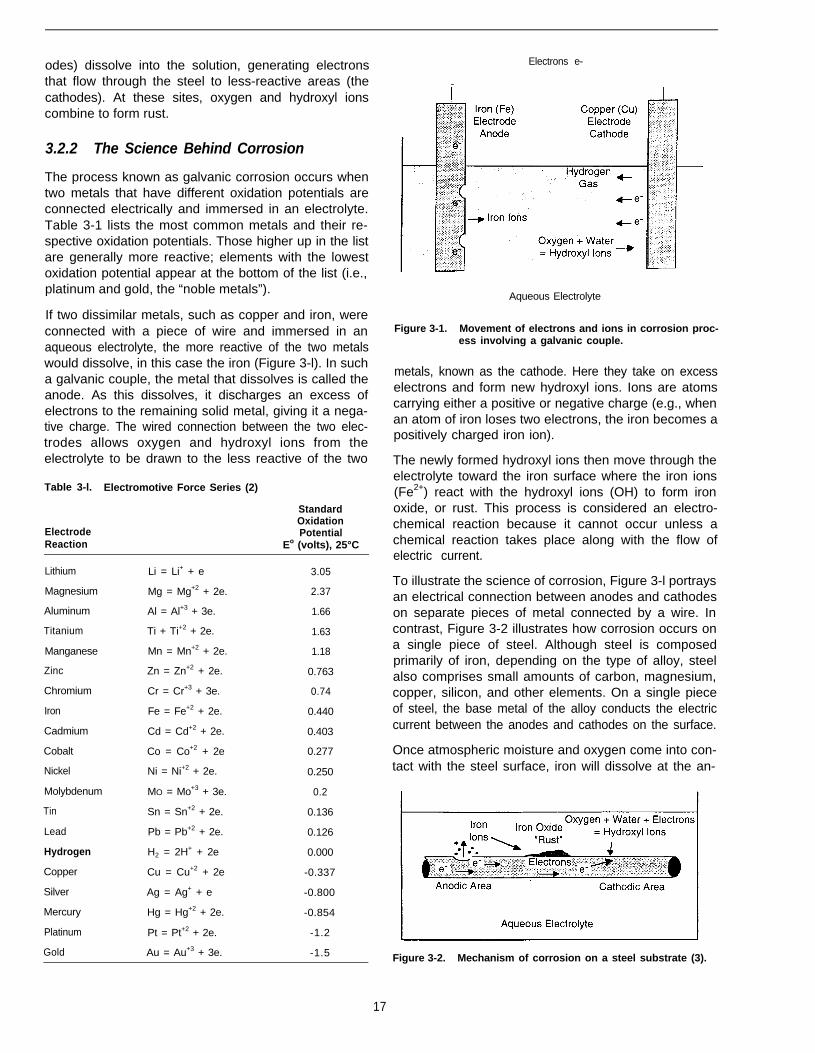
odes) dissolve into the solution, generating electronsthat flow through the steel to less-reactive areas (thecathodes). At these sites, oxygen and hydroxyl ionscombine to form rust.
3.2.2 The Science Behind Corrosion
The process known as galvanic corrosion occurs whentwo metals that have different oxidation potentials areconnected electrically and immersed in an electrolyte.Table 3-1 lists the most common metals and their re-spective oxidation potentials. Those higher up in the listare generally more reactive; elements with the lowestoxidation potential appear at the bottom of the list (i.e.,platinum and gold, the “noble metals”).
If two dissimilar metals, such as copper and iron, wereconnected with a piece of wire and immersed in anaqueous electrolyte, the more reactive of the two metalswould dissolve, in this case the iron (Figure 3-l). In sucha galvanic couple, the metal that dissolves is called theanode. As this dissolves, it discharges an excess ofelectrons to the remaining solid metal, giving it a nega-tive charge. The wired connection between the two elec-trodes allows oxygen and hydroxyl ions from theelectrolyte to be drawn to the less reactive of the two
Table 3-l. Electromotive Force Series (2)
ElectrodeReaction
Lithium
Magnesium
Aluminum
Titanium
Manganese
Zinc
Chromium
Iron
Cadmium
Cobalt
Nickel
Molybdenum
Tin
Lead
Hydrogen
Copper
Silver
Mercury
Platinum
Gold
Li = Li+ + e
Mg = Mg+2 + 2e.
Al = Al+3 + 3e.
Ti + Ti+2 + 2e.
Mn = Mn+2 + 2e.
Zn = Zn+2 + 2e.
Cr = Cr+3 + 3e.
Fe = Fe+2 + 2e.
Cd = Cd+2 + 2e.
Co = Co+2 + 2e
Ni = Ni+2 + 2e.
MO = Mo+3 + 3e.
Sn = Sn+2 + 2e.
Pb = Pb+2 + 2e.
H2 = 2H+ + 2e
Cu = Cu+2 + 2e
Ag = Ag+ + e
Hg = Hg+2 + 2e.
Pt = Pt+2 + 2e.
Au = Au+3 + 3e.
StandardOxidationPotential
Eo (volts), 25°C
3.05
2.37
1.66
1.63
1.18
0.763
0.74
0.440
0.403
0.277
0.250
0.2
0.136
0.126
0.000
-0.337
-0.800
-0.854
-1.2
-1.5
Electrons e-
-
Aqueous Electrolyte
Figure 3-1. Movement of electrons and ions in corrosion proc-ess involving a galvanic couple.
metals, known as the cathode. Here they take on excesselectrons and form new hydroxyl ions. Ions are atomscarrying either a positive or negative charge (e.g., whenan atom of iron loses two electrons, the iron becomes apositively charged iron ion).
The newly formed hydroxyl ions then move through theelectrolyte toward the iron surface where the iron ions(Fe2+) react with the hydroxyl ions (OH) to form ironoxide, or rust. This process is considered an electro-chemical reaction because it cannot occur unless achemical reaction takes place along with the flow ofelectric current.
To illustrate the science of corrosion, Figure 3-l portraysan electrical connection between anodes and cathodeson separate pieces of metal connected by a wire. Incontrast, Figure 3-2 illustrates how corrosion occurs ona single piece of steel. Although steel is composedprimarily of iron, depending on the type of alloy, steelalso comprises small amounts of carbon, magnesium,copper, silicon, and other elements. On a single pieceof steel, the base metal of the alloy conducts the electriccurrent between the anodes and cathodes on the surface.
Once atmospheric moisture and oxygen come into con-tact with the steel surface, iron will dissolve at the an-
Figure 3-2. Mechanism of corrosion on a steel substrate (3).
17
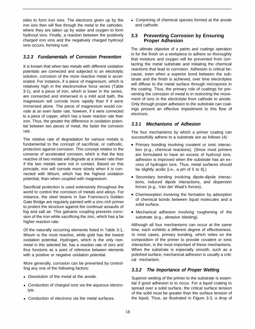
odes to form iron ions. The electrons given up by theiron ions then will flow through the metal to the cathodes,where they are taken up by water and oxygen to formhydroxyl ions. Finally, a reaction between the positivelycharged iron ions and the negatively charged hydroxylions occurs, forming rust.
3.2.3 Fundamentals of Corrosion Prevention
It is known that when two metals with different oxidationpotentials are connected and subjected to an electrolyticsolution, corrosion of the more reactive metal is accel-erated. For instance, if a piece of magnesium, which isrelatively high in the electromotive force series (Table3-1), and a piece of iron, which is lower in the series,are connected and immersed in a mild acid bath, themagnesium will corrode more rapidly than if it wereimmersed alone. The piece of magnesium would cor-rode at an even faster rate, however, if it were connectedto a piece of copper, which has a lower reaction rate thaniron. Thus, the greater the difference in oxidation poten-tial between two pieces of metal, the faster the corrosionrate.
The relative rate of degradation for various metals isfundamental to the concept of sacrificial, or cathodic,protection against corrosion. This concept relates to theconverse of accelerated corrosion, which is that the lessreactive of two metals will degrade at a slower rate thanif the two metals were not in contact. Based on thisprinciple, iron will corrode more slowly when it is con-nected with lithium, which has the highest oxidationpotential, than when coupled with magnesium.
Sacrificial protection is used extensively throughout theworld to control the corrosion of metals and alloys. Forinstance, the steel beams in San Francisco’s GoldenGate Bridge are regularly painted with a zinc-rich primerto protect the structure against the continua! assaults offog and salt air. This galvanic coupling prevents corro-sion of the iron while sacrificing the zinc, which has a farhigher reaction rate.
Of the naturally occurring elements listed in Table 3-1,lithium is the most reactive, while gold has the lowestoxidation potential. Hydrogen, which is the only non-metal in this selected list, has a reaction rate of zero andthus functions as a point of reference between elementswith a positive or negative oxidation potential.
More generally, corrosion can be prevented by control-ling any one of the following factors:
l Dissolution of the metal at the anode.
l Conduction of charged ions via the aqueous electro-lyte.
l Conduction of electrons via the metal surfaces.
l Conjoining of chemical species formed at the anodeand cathode.
3.3 Preventing Corrosion by EnsuringProper Adhesion
The ultimate objective of a paints and coatings operationis for the finish on a workpiece to adhere so thoroughlythat moisture and oxygen will be prevented from con-tacting the metal substrate and initiating the chemicalreactions that lead to corrosion. Adhesion is critical be-cause, even when a superior bond between the sub-strate and the finish is achieved, over time electrolyteswill diffuse to the metal surface through micropores inthe coating. Thus, the primary role of coatings for pre-venting the corrosion of metal is in restricting the move-ment of ions in the electrolyte from cathode to anode.Only through proper adhesion to the substrate can coat-ings present an effective impediment to this flow ofelectrons.
3.3.1 Mechanisms of Adhesion
The four mechanisms by which a primer coating cansuccessfully adhere to a substrate are as follows (4):
Primary bonding involving covalent or ionic interac-tion (e.g., chemical reactions). (Since most primersare formulated to have an excess of hydroxyl ions,adhesion is improved when the substrate has an ex-cess of hydrogen ions. Thus, metal surfaces shouldbe slightly acidic [i.e., a pH of 5 to 6].)
Secondary bonding involving dipole-dipole interac-tions, induced dipole interactions, and dispersionforces (e.g., Van der Waal’s forces).
Chemisorption involving the formation by adsorptionof chemical bonds between liquid molecules and asolid surface.
Mechanical adhesion involving roughening of thesubstrate (e.g., abrasive blasting).
Although all four mechanisms can occur at the sametime, each exhibits a different degree of effectiveness.In most cases, primary bonding, which relies on thecomposition of the primer to provide covalent or ionicinteraction, is the most important of these mechanisms.When the substrate is especially smooth, such as apolished surface, mechanical adhesion is usually a criti-cal mechanism.
3.3.2 The Importance of Proper Wetting
Superior wetting of the primer to the substrate is essen-tial if good adhesion is to occur. For a liquid coating tospread over a solid surface, the critical surface tensionof the solid must be greater than the surface tension ofthe liquid. Thus, as illustrated in Figure 3-3, a drop of
18
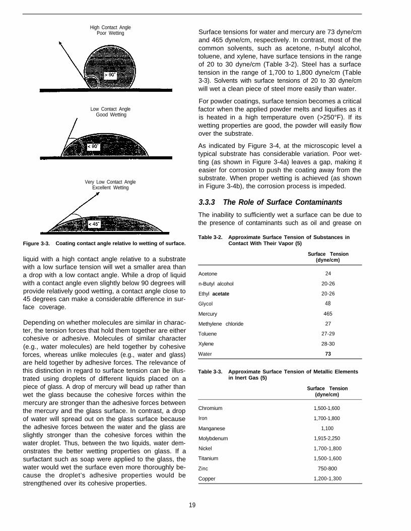
High Contact AnglePoor Wetting
Low Contact AngleGood Wetting
Very Low Contact AngleExcellent Wetting
Figure 3-3. Coating contact angle relative lo wetting of surface.
liquid with a high contact angle relative to a substratewith a low surface tension will wet a smaller area thana drop with a low contact angle. While a drop of liquidwith a contact angle even slightly below 90 degrees willprovide relatively good wetting, a contact angle close to45 degrees can make a considerable difference in sur-face coverage.
Depending on whether molecules are similar in charac-ter, the tension forces that hold them together are eithercohesive or adhesive. Molecules of similar character(e.g., water molecules) are held together by cohesiveforces, whereas unlike molecules (e.g., water and glass)are held together by adhesive forces. The relevance ofthis distinction in regard to surface tension can be illus-trated using droplets of different liquids placed on apiece of glass. A drop of mercury will bead up rather thanwet the glass because the cohesive forces within themercury are stronger than the adhesive forces betweenthe mercury and the glass surface. In contrast, a dropof water will spread out on the glass surface becausethe adhesive forces between the water and the glass areslightly stronger than the cohesive forces within thewater droplet. Thus, between the two liquids, water dem-onstrates the better wetting properties on glass. If asurfactant such as soap were applied to the glass, thewater would wet the surface even more thoroughly be-cause the droplet’s adhesive properties would bestrengthened over its cohesive properties.
Surface tensions for water and mercury are 73 dyne/cmand 465 dyne/cm, respectively. In contrast, most of thecommon solvents, such as acetone, n-butyl alcohol,toluene, and xylene, have surface tensions in the rangeof 20 to 30 dyne/cm (Table 3-2). Steel has a surfacetension in the range of 1,700 to 1,800 dyne/cm (Table3-3). Solvents with surface tensions of 20 to 30 dyne/cmwill wet a clean piece of steel more easily than water.
For powder coatings, surface tension becomes a criticalfactor when the applied powder melts and liquifies as itis heated in a high temperature oven (>250°F). If itswetting properties are good, the powder will easily flowover the substrate.
As indicated by Figure 3-4, at the microscopic level atypical substrate has considerable variation. Poor wet-ting (as shown in Figure 3-4a) leaves a gap, making iteasier for corrosion to push the coating away from thesubstrate. When proper wetting is achieved (as shownin Figure 3-4b), the corrosion process is impeded.
3.3.3 The Role of Surface Contaminants
The inability to sufficiently wet a surface can be due tothe presence of contaminants such as oil and grease on
Table 3-2. Approximate Surface Tension of Substances inContact With Their Vapor (5)
Surface Tension(dyne/cm)
Acetone 24
n-Butyl alcohol 20-26
Ethyl acetate 20-26
Glycol 48
Mercury 465
Methylene chloride 27
Toluene 27-29
Xylene 28-30
Water 73
Table 3-3. Approximate Surface Tension of Metallic Elementsin Inert Gas (5)
Surface Tension(dyne/cm)
Chromium 1,500-1,600
Iron 1,700-1,800
Manganese 1,100
Molybdenum 1,915-2,250
Nickel 1,700-1,800
Titanium 1,500-1,600
Zinc 750-800
Copper 1,200-1,300
19
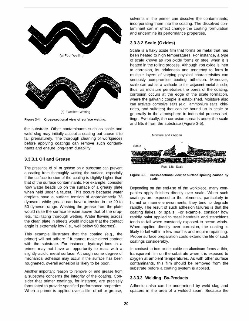
(b) Excellent Wetting
Figure 3-4. Cross-sectional view of surface wetting.
the substrate. Other contaminants such as scale andweld slag may initially accept a coating but cause it tofail prematurely. The thorough cleaning of workpiecesbefore applying coatings can remove such contami-nants and ensure long-term durability.
3.3.3.1 Oil and Grease
The presence of oil or grease on a substrate can preventa coating from thoroughly wetting the surface, especiallyif the surface tension of the coating is slightly higher thanthat of the surface contaminants. For example, considerhow water beads up on the surface of a greasy platewhen held under a faucet. This occurs because waterdroplets have a surface tension of approximately 73dyne/cm, while grease can have a tension in the 20 to50 dyne/cm range. Washing the grease from the platewould raise the surface tension above that of the drop-lets, facilitating thorough wetting. Water flowing acrossthe clean plate in sheets would indicate that the contactangle is extremely low (i.e., well below 90 degrees).
This example illustrates that the coating (e.g., theprimer) will not adhere if it cannot make direct contactwith the substrate. For instance, hydroxyl ions in aprimer may not have an opportunity to react with aslightly acidic metal surface. Although some degree ofmechanical adhesion may occur if the surface has beenroughened, overall adhesion is likely to be poor.
Another important reason to remove oil and grease froma substrate concerns the integrity of the coating. Con-sider that primer coatings, for instance, are preciselyformulated to provide specified performance properties.When a primer is applied over a film of oil or grease,
solvents in the primer can dissolve the contaminants,incorporating them into the coating. The dissolved con-taminant can in effect change the coating formulationand undermine its performance properties.
3.3.3.2 Scale (Oxides)
Scale is a flaky oxide film that forms on metal that hasbeen heated to high temperatures. For instance, a typeof scale known as iron oxide forms on steel when it isheated in the rolling process. Although iron oxide is inertto corrosion, its brittleness and tendency to form inmultiple layers of varying physical characteristics canseriously compromise coating adhesion. Moreover,scale can act as a cathode to the adjacent metal anode;thus, as moisture penetrates the pores of the coating,corrosion occurs at the edge of the scale formation,where the galvanic couple is established. Moisture alsocan activate corrosive salts (e.g., ammonium salts, chlo-rides, and sulfates) that can be bound up in scale orgenerally in the atmosphere in industrial process set-tings. Eventually, the corrosion spreads under the scaleand lifts it from the substrate (Figure 3-5).
Moisture and Oxygen
Scale
Rust Lifts Scale
Figure 3-5. Cross-sectional view of surface spalling caused byscale.
Depending on the end-use of the workpiece, many com-panies apply finishes directly over scale. When suchcoatings are exposed to the elements, particularly inhumid or marine environments, they tend to degraderapidly. The result of such adhesion failures is that thecoating flakes, or spalls. For example, consider howrapidly paint applied to steel handrails and stanchionstends to fail when constantly exposed to ocean winds.When applied directly over corrosion, the coating islikely to fail within a few months and require repainting.Proper surface preparation could extend the life of suchcoatings considerably.
In contrast to iron oxide, oxide on aluminum forms a thin,transparent film on the substrate when it is exposed tooxygen at ambient temperatures. As with other surfacecontaminants, this film should be removed from thesubstrate before a coating system is applied.
3.3.3.3 Welding By-Products
Adhesion also can be undermined by weld slag andspatters in the area of a welded seam. Because the
20

seam itself is highly prone to corrosion and is oftenwhere coating failure begins, thorough preparation ofsuch areas is particularly important. Like scale, weldslag can include corrosive substances that underminesurface adhesion when activated by moisture. In con-trast, spatters encourage premature corrosion by theirirregular profiles, often with sharp peaks, which makethem difficult to cover and likely to protrude from thecoating (Figure 3-6). Another concern is that the areaaround a weld seam can be slightly alkaline. This cancause a compatibility problem with the primer, whichshould be applied to metal substrates that are slightlyacidic (i.e., a pH of 5 to 6).
The most effective approach for preparing a weldedsurface before painting calls for removing all spattersand slag material, either through grinding or abrasiveblasting. The weld seams should then be thoroughlywiped down using a cloth moistened with a low concen-tration phosphoric acid to adjust the pH.
Additional preventive measures include brushing theweld seam with a corrosion-resistant primer beforespraying the entire piece with the primer coat. Thisadditional step ensures that the primer covers most ifnot all surface irregularities. One company using thislabor-intensive approach reports that an earlier problemwith paint failures around weld seams has been essen-tially eliminated.
3.4 Adhesion Considerations Specific toPlastic Substrates
Plastics are complex organic composites that present aparticular challenge to paints and coatings operations.For example, most plastics have a surface tension in thesame range as organic coatings, making adhesion gen-erally problematic (Table 3-4). To some degree, thischallenge can be addressed with the use of coatingsspecifically formulated for a lower surface tension.Because the range for adjustment is quite narrow, how-
Weld Spatter
ever, ensuring that the substrate is free of contaminantsis even more important for coating plastics than formetals. Of particular concern are release agents (e.g.,wax or silicone oil), which are used during moldingoperations to keep the surface of the workpiece fromadhering to the form. Additionally, plasticizers which areadded to the plastics blend to enhance flexibility, cancontaminate the substrate. In some cases, plasticizersmigrate to the surface over time to undermine a work-piece’s long-term durability.
For most plastic workpieces, thorough cleaning of thesurface ensures that coating adhesion meets end-usespecifications. Certain plastics, however, such aspolypropylene, are so inert that additional pretreatmentmay be required. Recommended approaches includelight abrasion of the surface or heating the workpiece toalter the chemical characteristics of the substrate (e.g.,using hot flame or gas plasma technology).
3.5 References1.
2.
3.
4.
5.
6.
Joseph, R. 1993. Pollution prevention for paints and coatings fa-cilities: Why the need for surface preparation? Presented at train-ing seminar on Liquid and Powder Coating Operations, November16-18, New Orleans, LA. Sponsored by University of California-Berkeley.
Uhlig, H.H. 1965. Corrosion and corrosion control. New York, NY:John Wiley and Sons.
Joseph, R. 1988. How paints and coatings reduce corrosion: Ashort introduction. Saratoga, CA: Ron Joseph & Associates.
Wegman, R. 1989. Surface preparation techniques for adhesivebonding. Park Ridge, NJ: Noyes Publications.
Lide, D.R. 1992. Handbook of chemistry and physics, 72nd ed.Boca Raton, FL: CRC Press.
Hajas, J., K. Haubennestel, and A. Bubat. 1994. Improvements ofsubstrate wetting of waterborne coatings on plastics and relatedsurfaces, In: Proceedings of the 24th Waterborne, Higher Solids,and Powder Coating Symposium, February 9-11, New Orleans,LA. Sponsored by the University of Southern Mississippi, Depart-ment of Polymer Science, and the Southern Society for CoatingsTechnology.
Figure 3-6. Cross-sectional view of compromising effect of weld slag and spatters on a coating.
21
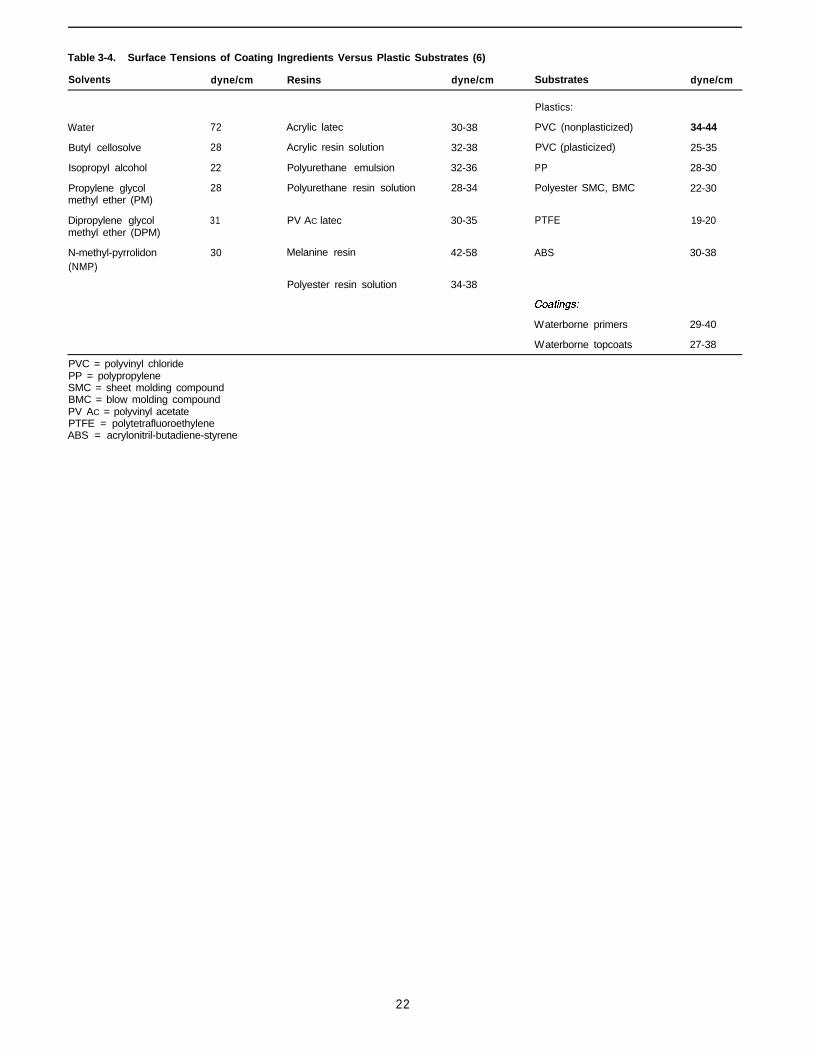
Table 3-4. Surface Tensions of Coating Ingredients Versus Plastic Substrates (6)
Solvents dyne/cm Resins dyne/cm Substrates dyne/cm
Water
Butyl cellosolve
Isopropyl alcohol
Propylene glycolmethyl ether (PM)
Dipropylene glycolmethyl ether (DPM)
N-methyl-pyrrolidon(NMP)
72
28
22
28
31
30
Acrylic latec 30-38
Acrylic resin solution 32-38
Polyurethane emulsion 32-36
Polyurethane resin solution 28-34
PV AC latec 30-35 PTFE 19-20
Melanine resin 42-58 ABS 30-38
Polyester resin solution 34-38
Plastics:
PVC (nonplasticized)
PVC (plasticized)
PP
Polyester SMC, BMC
34-44
25-35
28-30
22-30
PVC = polyvinyl chloridePP = polypropylene
Waterborne primers 29-40
Waterborne topcoats 27-38
SMC = sheet molding compoundBMC = blow molding compoundPV AC = polyvinyl acetatePTFE = polytetrafluoroethyleneABS = acrylonitril-butadiene-styrene
22
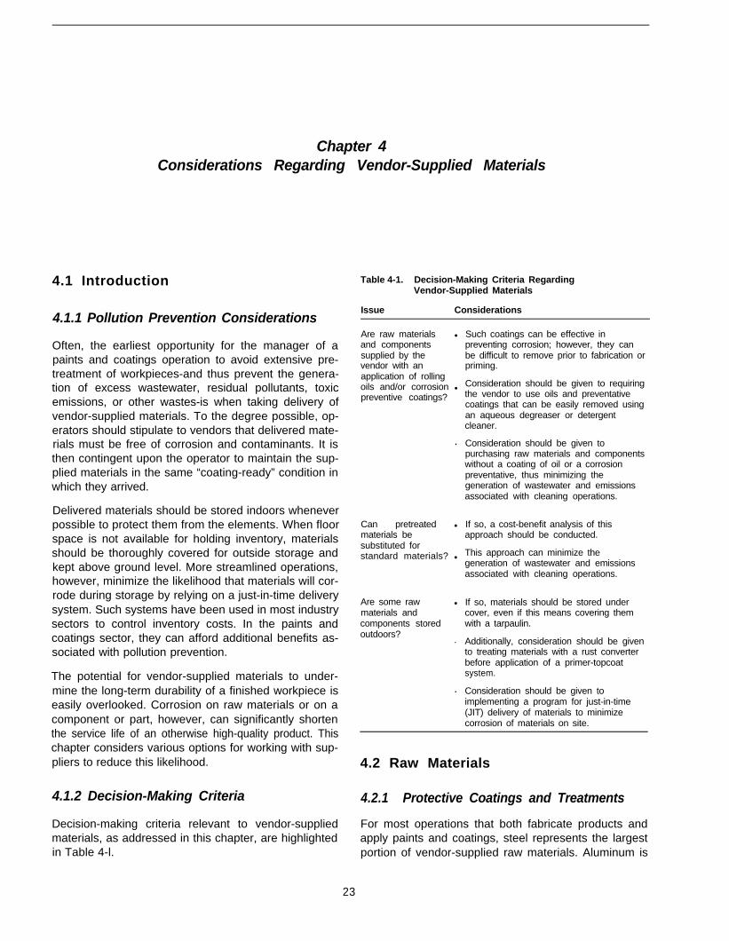
Chapter 4Considerations Regarding Vendor-Supplied Materials
4.1 Introduction
4.1.1 Pollution Prevention Considerations
Often, the earliest opportunity for the manager of apaints and coatings operation to avoid extensive pre-treatment of workpieces-and thus prevent the genera-tion of excess wastewater, residual pollutants, toxicemissions, or other wastes-is when taking delivery ofvendor-supplied materials. To the degree possible, op-erators should stipulate to vendors that delivered mate-rials must be free of corrosion and contaminants. It isthen contingent upon the operator to maintain the sup-plied materials in the same “coating-ready” condition inwhich they arrived.
Delivered materials should be stored indoors wheneverpossible to protect them from the elements. When floorspace is not available for holding inventory, materialsshould be thoroughly covered for outside storage andkept above ground level. More streamlined operations,however, minimize the likelihood that materials will cor-rode during storage by relying on a just-in-time deliverysystem. Such systems have been used in most industrysectors to control inventory costs. In the paints andcoatings sector, they can afford additional benefits as-sociated with pollution prevention.
The potential for vendor-supplied materials to under-mine the long-term durability of a finished workpiece iseasily overlooked. Corrosion on raw materials or on acomponent or part, however, can significantly shortenthe service life of an otherwise high-quality product. Thischapter considers various options for working with sup-pliers to reduce this likelihood.
4.1.2 Decision-Making Criteria
Decision-making criteria relevant to vendor-suppliedmaterials, as addressed in this chapter, are highlightedin Table 4-l.
Table 4-1. Decision-Making Criteria RegardingVendor-Supplied Materials
Issue Considerations
Are raw materials l
and componentssupplied by thevendor with anapplication of rollingoils and/or corrosion lpreventive coatings?
.
Can pretreated l
materials besubstituted forstandard materials? l
Are some raw l
materials andcomponents storedoutdoors?
.
.
Such coatings can be effective inpreventing corrosion; however, they canbe difficult to remove prior to fabrication orpriming.
Consideration should be given to requiringthe vendor to use oils and preventativecoatings that can be easily removed usingan aqueous degreaser or detergentcleaner.
Consideration should be given topurchasing raw materials and componentswithout a coating of oil or a corrosionpreventative, thus minimizing thegeneration of wastewater and emissionsassociated with cleaning operations.
If so, a cost-benefit analysis of thisapproach should be conducted.
This approach can minimize thegeneration of wastewater and emissionsassociated with cleaning operations.
If so, materials should be stored undercover, even if this means covering themwith a tarpaulin.
Additionally, consideration should be givento treating materials with a rust converterbefore application of a primer-topcoatsystem.
Consideration should be given toimplementing a program for just-in-time(JIT) delivery of materials to minimizecorrosion of materials on site.
4.2 Raw Materials
4.2.1 Protective Coatings and Treatments
For most operations that both fabricate products andapply paints and coatings, steel represents the largestportion of vendor-supplied raw materials. Aluminum is
23
also widely used in fabrication because it is lightweightand less susceptible to corrosion. Depending on how itwill be used in the manufacture of a workpiece, the rawmaterial may be delivered in the form of plates, sheets,or extrusions. Milling operations typically involve appli-cation of one of the following types of coatings:
Rolling oils, which are lubricants used to minimizefriction between the metal and the pressing machin-ery; also, these oils provide some corrosion protec-tion, primarily during transportation and short-termstorage.
Corrosion preventatives, which are organic formula-tions used specifically to protect the substrate in thelonger term (e.g., by displacing condensed moisture).
Although important for minimizing the corrosion of metalbetween milling and the application of a finish coating,protective coatings can be difficult to remove, especiallyif they have been on the substrate for an extendedperiod. Whereas some of the coating may be removedincidentally during fabrication, manufactured work-pieces are likely to require extensive washing or abra-sive blasting before surfaces are sufficiently clean toreceive paint. Thorough washing can consume largevolumes of water, and many of the degreasers in useare solvent based, raising process management issuesinvolving toxic emissions and contaminated wastewater(see Chapter 5). Some situations may require the useof several solvents to remove protective coatings, fur-ther complicating the overall process. Abrasive blastingcan raise other pollution prevention considerations,such as dust generation (see Chapter 8).
To minimize process demands and wastewater out-flows, the facility operator should specify that vendorsonly use protective coatings that can be readily removedby washing with one of the following:
l Ambient water and an aqueous degreaser
l Hot water and a detergent solution
l Steam or high-pressure water
Alternatively, the facility operator could purchasespecially treated raw materials that would not requireapplication of a corrosion preventative before delivery.Galvanized steel, for instance, receives a depositioncoating of zinc during the milling process to providecorrosion resistance. Similarly, stainless steel in-cludes other elements (e.g., chromium, nickel, molyb-denum) that make the alloy nearly immune to ordinaryrusting. While these alternatives can be more expen-sive, the cost should be weighed against savings interms of avoided process steps and reduced wastegeneration.
Another alternative is for the fabricator to use raw ma-terials that have been precoated by the vendor. Coil
coating, powder coating, and electrodeposition opera-tions all generally yield a vendor-applied finish that issufficiently resilient for the fabricator to post-form work-pieces from the stock material. For instance, often sheetsteel or aluminum undergoes coil coating operations inwhich the surface is thoroughly cleaned before a whiteor neutral-tone finish is applied. This material can be cutand punched in forming operations with little or no dam-age to the surface. Usually there is no need for thefabricator to apply a topcoat to the workpiece after form-ing operations.
4.2.2 Storage
Vendor-supplied raw materials should be carefullystored so that they will not be subjected to moisture andcontamination. This is especially important for metal thathas received neither a protective coating or undergonesome type of pretreatment. Because steel is particularlyvulnerable to corrosion, it should be stored indoors whenpossible. When outside storage is the only option, ma-terials should be well covered and raised above theground. Protection from the elements is of particularconcern in humid or marine environments.
If steel begins to corrode while in storage, the operatormay be able to arrest the process with a rust converter,a chemical formulation that converts iron oxide to inertmatter. Depending on the durability requirements of theworkpiece, a primer can be applied directly over thetreated substrate, which with most converter formula-tions turns black within minutes. For long-term durability,the chemicals and oxides should be cleaned from thesteel before a coating system is applied, either throughsurface degreasing or abrasive blasting.
4.3 Components and Parts
4.3.1 Protective Coatings and Primers
Operations that apply paints and coatings to work-pieces assembled on site using vendor-supplied com-ponents and parts should be attentive to the conditionof delivered materials. Often, an establishment will go togreat lengths to ensure that the surfaces of its fabricatedpieces are thoroughly prepared for finish coating whileoverlooking the substrate quality of supplied compo-nents. A component or part that corrodes prematurely,however, can undermine the overall quality of an assem-bled product.
To avoid problems with supplied components and parts,the operator should require that the vendor supply ma-terials with a protective coating that is consistent withthe primer-finish coating system that will be applied. Theoperator may want to specify the use of compositionsthat can be removed using a nonsolvent degreaser ordetergent.
24

For some materials, a primer coat will need to be appliedby the vendor. When the vendor is supplying assembledcomponents that include sophisticated electronics orcomputer circuits, for instance, the operator should bedirectly involved in the selection of the undercoating.Such sensitive and expensive components cannot bereadily cleaned and reprimed after delivery if the under-coating is found to be incompatible with the finish coat-ing. Moreover, whenever components and parts must becleaned and reprimed, the operator incurs added costsand generates unnecessary wastes. Operators shouldalways specify the use of corrosion-resistant primersthat are in keeping with workpiece quality specifications.Additionally, operators should require the use of pre-treated (e.g., galvanized steel) or finish coated (e.g.,electrocoated) materials when appropriate.
4.3.2 Storage
Storing components and parts to protect them frommoisture and contaminants often is even more importantthan it is for raw materials. The substrate of a sophisti-cated assembly that begins to corrode while in storagemay be impossible to thoroughly clean. Similarly, partsmay have intricate geometries that hide contaminants orthe beginnings of corrosion from view. For these rea-sons, along with their generally high value, componentsand parts should be stored indoors whenever possible.When stored outdoors, they should be completelywrapped for protection and inspected routinely.
4.4 Just-in-Time Delivery
Just-in-time delivery of supplies is practiced by manycompanies to control costs through the careful manage-ment of inventory. For paints and coatings operations,however, this technique can also present opportunitiesfor avoiding the cost of additional pretreatment for ma-terials that have begun to corrode while stored on site.The degradation of vendor-supplied materials is a par-ticular concern for establishments that increasingly dedi-cate available floor space to operations in an effort to
remain competitive, while resorting to yard storage ofinventory.
At the least, implementing such a program will free upfloor space and minimize the contamination of raw ma-terials and components. In the best case, close controlof inventory might eliminate the need to receive vendor-supplied materials with a corrosion-prevention coatingthat ultimately must be cleaned from the substrate.
To implement a successful just-in-time inventory pro-gram, the operator must work in close coordination withsuppliers. Generally, this requires establishing computerlinks that enable the operator and principal suppliers toshare inventory data so that they can work together inthe tracking and in-time delivery of materials. This linkis often established using a computer networking sys-tem called electronic data interchange, or EDI. In ahighly sophisticated undertaking, computers also can beused to model material consumption patterns, providingadditional data for refining inventory needs. In someindustry sectors, cooperative efforts between producersand suppliers have evolved into strategic “partnerships”in the management of inventory, significantly reducingthe amount of time materials remain on site before theyare needed (1).
Even without computer links, operators should be inregular contact with their principal suppliers in an effortto minimize the need to manage excess inventory thatis prone to corrosion. Frequent communication with sup-pliers will reduce the potential for misunderstandingsabout the need for coating-ready materials. Moreover,regular contact will afford an opportunity for the operatorto implement and oversee a policy according to whichmaterials would only be accepted if delivered in theiragreed-upon condition.
4.5 References
1. The Economist. 1995. Survey on retailing: Stores of value. March 4.pp. 5-6.
25
Chapter 5Surface Degreasing: Alternatives to Conventional Solvent-Based Methods
5.1 Introduction
5.1.1 Pollution Prevention Considerations
Thorough degreasing of a workpiece is an essentialpretreatment step in the paints and coatings process forensuring proper adhesion. Even exemplary applicationprocesses and superior coatings cannot provide a rea-sonable measure of durability if the various oils andgreases, corrosion products, waxy films, and tars that canbecome attached to a substrate are not first cleared away.
Unfortunately, many of the chemical agents that are themost effective for removing such contaminants from aworkpiece raise significant concerns about pollution. In-deed, solvents in several conventional degreasers arestrictly regulated at the federal level and are scheduledto be phased out of use early in the next decade underan international agreement. Facility operators thatchoose to use degreasers based on these particularsolvents in the interim will incur the additional costsassociated with controlling hazardous air emissions. Insome cases, the cost of the solvents themselves isbeing driven up by taxes that create an incentive forfacility operators to seek out less-toxic alternatives. Be-cause solvent-based degreasers are generally easy torecycle, however, operators will have opportunities tomaximize the use of currently available stocks.
At present, aqueous degreasers represent the best al-ternative to solvent-based formulations in regard to pol-lution preventions considerations. These water-basedsolutions are already widely used in the industry toremove an array of surface contaminants-from corro-sion to waxy films. Because they are less volatile anddo not pollute the atmosphere, aqueous degreasers aregenerally less expensive to use. Nonetheless, certainaqueous cleaning approaches can generate consider-able volumes of wastewater that must be treated beforebeing released to a publicly owned treatment works.Moreover, the use of aqueous formulations necessitatesthe addition of a rinse step to the degreasing stage.
For surface contaminants that are particularly difficult toremove, such as heavier grease and tar, semi-aqueousdegreasers present an alternative that lies between sol-vents and aqueous formulations. Whereas the organic
compounds in semi-aqueous degreasers are effectivecleaning agents, they are also considered hazardous airpollutants (HAPS). Because semi-aqueous degreasersare less toxic than solvents, however, they are easierand less expensive to use.
A potential third alternative is still in development. Re-searchers are working on hydrofluorocarbons (HFCs)that promise effectiveness in removing stubborn surfacecontaminants and pose little or no threat to air quality.Current indications are that the first of these may be-come available by the end of the decade.
These pollution prevention considerations are pre-sented in this chapter in the context of the variousapproaches currently used to degrease workpieces.Conventional solvent methods are discussed first, fol-lowed by aqueous alternatives.
5.1.2 Decision-Making Criteria
Decision-making criteria relevant to surface degreasingprocess efficiency and alternatives to conventional sol-vent-based methods, as addressed in this chapter, arehighlighted in Table 5-1.
5.2 Basic Practices and RegulatoryConsiderations
5.2.1 Typical Oils and Grime on Substrates
The operator of a paints and coatings facility shoulddetermine the best approach for cleaning workpiecesbased on an assessment of the particular types of con-taminants on the substrate. Typically, contaminants fallinto one or more of the following categories:
l Oil and grime with a relatively low viscosity such thatit easily flows at ambient temperatures. These con-taminants may contain chlorinated paraffins or sul-phurized oils. Generally, such material can beremoved with either a solvent-based or an aqueousdegreaser.
l Grime with a relative/y high viscosity such that it doesnot flow. These contaminants may include waxes,oxidized resins, and pastes or other soft and filmymatter. Generally, such material can only be removed
26

Table 5-l. Decision-Making Criteria Regarding Surface Degreasing Process Efficiency and Alternatives to ConventionalSolvent-Based Methods
Issue Considerations
Are the workpieces that need to becleaned large (e.g., assembledmachinery)?
Have the workpieces already receiveda primer coating and will the cleaningbe conducted to prepare surfaces fortopcoat application?
Are workpieces uncoated and will thecleaning be conducted to preparesurfaces for a primer-topcoat system?
Are the workpieces that need to becleaned small enough for vapordegreasing, cold cleaning, orconveyorized spray washing or forimmersion in a tank?
Are workpieces already being cleanedin a vapor degreaser using 1,1,1trichloroethane or CFC-113?
Is the use of a solvent-baseddegreaser necessary, although somedegree of residue can be tolerated?
Can pretreatment specifications be metwith the use of an aqueous degreaser?
Are the workpieces that need to becleaned too heavy to be cleaned in aconveyorized spray process?
Do the workpieces that need to becleaned have complex geometries(e.g., channels, box sections,crevices), making spray washing anineffective approach?
For the workpieces that need to becleaned, is the production ratesufficiently low that continuousdegreasing operations would not becost effective?
l If yes, then the most effective method would be to use high-pressure, super heated steam orhigh-pressure hot water.
l If yes, then cleaning with high-pressure hot water is recommended.
l Only a low concentration of detergent may be necessary (consult degreasing formulationvendor).
l A final rinse with hot tap water should follow the cleaning.
l If yes, then the most effective method would be to use high-pressure, super heated steam orhigh-pressure hot water.
l Only a low concentration of detergent may be necessary.
l A hot tap-water rinse with a small concentration of phosphoric acid should follow thecleaning; this will give the substrate a slight etch and lower its pH (making it more acidic),resulting in enhanced coating adhesion.
l If yes, then the use of high-pressure steam or high-pressure hot water might not be the mosteffective cleaning method.
l If yes, consider substituting such solvents with an aqueous degreasing system.
l Otherwise, consider near-term strategies such as substituting with methylene chloride,perchloroethylene, or trichloroethylene.
l Other possible temporary substitutes to consider would include alternative HCFCs.
l Factors to consider when selecting an alternative degreaser include: the nature of the grimeon workpieces, the thoroughness of cleaning required for the particular end-product’sapplication, and workpiece drying considerations.
l If yes, consider using a solvent that has a high boiling point and low vapor pressure toprevent unnecessary toxic air emissions.
l Regardless, avoid the use of listed hazardous air pollutants and ozone-depleting compounds.
l Experiment with alternative solvents to achieve the required substrate cleanliness (e.g., somecold cleaning approaches, in which the workpiece is immersed in a bath, can leave aresidue).
l Give strong consideration to the use of a semi-aqueous formulation (i.e., an emulsioncomprising solvents and water).
l Use of a semi-aqueous formulation in a degreasing process should include multiple rinses,using deionized water for the final rinse; additionally, workpieces should be dried with forcedair.
l If yes, consider using these less-toxic formulations, many of which have been proveneffective through widespread use by the industry.
l Aqueous degreasing processes should be given particularly close consideration for newfacilities.
l If yes, consider a system of one or more immersion tanks.
l For enhanced, cost-effective cleaning, consider a system in which the workpiece is immersedfirst in a bath of aqueous degreaser (i.e., water, detergent, surfactants, and other chemicals)followed by at least a tap-water rinse.
l If yes, same as above.
l If yes, same as above.
l As a rule of thumb, a degreasing operation that cleans less than 2 feet of production perminute is considered too slow to be cost-effective as a continuous operation.
27

Table 5-l. Decision-Making Criteria Regarding Surface Degreasing Process Efficiency and Alternatives to ConventionalSolvent-Based Methods (continued)
Issue Considerations
For the workpieces that need to becleaned, is the production rate highenough to justify using a continuoussystem?
l If yes, consider a conveyorized spray process.
l For enhanced, cost-effective cleaning, consider a system in which the workpiece is sprayedwith an aqueous degreaser (i.e., water, detergent, surfactants, and other chemicals) followedby at least a tap-water rinse.
Regardless of the degreasingapproach used, must the cleanedworkpieces be dried rapidly to avoidthe onset of flash rusting?
l If yes, it is likely that a high-temperature oven (at 230o to 400°F) will need to be included inthe process line.
at higher temperatures or by using stronger solventsor higher-concentration aqueous degreasers.
l Grime that may contain abrasives, carbonized films,buffing compounds, welding smut, metal or plastic chipsand fines, dust, and even rust and scale (i.e., oxidesformed during hot working of the metal). Generally,such material can only be removed using particularlystrong inorganic acids or specialty chemicals.
5.2.2 Basic Cleaning Approaches
Workpieces can be cleaned using any combination ofthe following basic approaches (1):
Cleaning by mechanical or physical means, such asmachining, abrading, pressure spraying, brushing, orwiping.
Dissolving/washing by application of a chemicalsolvent.
Washing/dissolving by application of an aqueous so-lution.
Displacing/washing by application of a detergent (i.e.,applying surface-active materials that displace thegrime).
For general purpose workpieces, most cleaning opera-tions involve either immersion of the piece in a tank ofdegreasing solution (batch operations) or spraying thepiece with solution at low pressure (continuous, or con-veyorized, operations). Immersion is generally recom-mended for smaller workpieces (i.e., component partswithout electrical wiring), especially those with complexgeometries (1). Whether to agitate the immersion solu-tion can depend partially on the type of degreaser used(see Section 5.3.2 on Degreasing with Liquid Solvent).Spraying may be required for large workpieces, such astruck bodies, or when the additional contaminant re-moval afforded by impingement is an advantage.
5.2.3 Selecting a Cleaning Approach
A facility operator should follow the recommended stepsoutlined below when selecting an approach for cleaningparticular types of workpieces (2):
1.
2.
3.
4.
5.
6.
Determine the level of part cleanliness required.Such an assessment must be based on the process-flow design of the particular operation (e.g., will ahigh level of cleanliness extend the useful life ofsubsequent baths?) as well as the quality require-ments of the finished workpiece (e.g., do specifica-tions call for a coating with long-term durability inextreme use conditions?).
Research and make preliminary selections of themost appropriate degreasers and associated equip-ment for achieving the required level of cleaning.This involves reviewing vendor literature and consid-ering the cost and waste-generation implications ofvarious options.
Test run selected degreasers and associated equip-ment to confirm satisfactory performance under allanticipated operating conditions. Operators shouldtest similar degreasers from more than one vendorbecause a slight variation in formulation can resultin a higher level of effectiveness. Even generic de-greasers can vary in their formulations.
Negotiate price with vendors of degreaser and asso-ciated equipment. It pays to shop around, particularlywhen the operator has tested similar products thatyield nearly the same results. In negotiating, theoperator may want to establish that the vendor willprovide training and support in use of the productand any associated equipment.
Make final selections and apply for any operationaland waste-related permits required by federal, state,or local authorities. The operator may need to estab-lish or modify recordkeeping procedures based onpermit requirements (e.g., for reporting on emis-sions, water discharges, and waste disposal).
implement the cleaning approach. The operatorshould allow sufficient startup time for training em-ployees and to refine the process. Quality controlprocedures should be developed and distributed.
28
5.2.4 Regulatory Overview
When assessing the appropriateness of various de-greasers for a particular process, the facility operatorshould investigate the applicability of federal, state, orlocal regulations concerning the use of specific cleaningagents. The costs associated with some requirementscan make the use of some solvent-based degreasersprohibitive, particularly for smaller operations. Most con-ventional solvent-based degreasers used in paints andcoatings operations come under the following regula-tions:
l Title III of the Clean Air Act Amendments of 1990:This federal regulation establishes limits on the emis-sion of HAPS, including those from certain degreas-ing solvents. Operations whose solvent emissionsexceed these limits may be required to perform riskanalyses and to install Maximum Achievable ControlTechnology (MACT).
l Occupational Safety and Health Administration(OSHA) regulations: These federal regulations estab-lish limits on emissions of HAPS from materials con-sidered particularly hazardous, including those fromcertain degreasing solvents.
l The Montreal Protocol: This international agreementand subsequent related federal regulations requirethat certain ozone-depleting compounds (ODCs) bephased out within the next several years. Under thisagreement, the use of chlorofluorocarbon 113 (CFC-113) and 1,1,1 trichloroethane (methyl chloroform),the two most commonly used compounds in vapordegreasing operations, will be banned by 2000 and2002, respectively. In the United States, the manu-facture of both compounds will cease after 1995,leaving several years for inventories to be exhausted.Also under this agreement, fluorinated hydrocarbons(HCFCs), some of which also are included in solvent-based formulations, are expected to be phased outbetween 2020 and 2040.
l State permit rules: Under the Clean Air Act Amend-ments (i.e., the Title V Permit Rule), states are re-quired to monitor “major” source categories of variouspollutants, including compounds found in many de-greasing solvents. Thus, facility operators must applyfor a state permit before using solvent degreasersthat include regulated compounds. Applications forTitle V permits are required as of 1995; state compli-ance officials notify facility operators directly aboutthe deadline for submitting an application. State offi-cials may determine that an operation comes withinthe “minor” source category based on an assessmentof the concentrations of listed compounds the appli-cant expects to use and the effectiveness of emissioncontrol equipment. The advantage of being desig-
nated a minor source is that applicable requirementsare less stringent.
State implementation Plans (SIPS): These programsmonitor emissions of volatile organic compounds(VOCs), including those from solvent degreasers andsolvent cleaning operations. Facility operators are ad-vised to become familiar with VOC regulations in thestate in which their facility is located.
More detailed information on regulatory considerationsspecific to the paints and coatings industry is availablein the literature (3-5).
5.3 Solvent-Based Methods
Solvent-based methods for degreasing and cleaning’workpieces have been widely used throughout the in-dustry for many years because they are particularlyeffective for removing surface contaminants from metalsand high-performance plastics. Moreover, because theyclean thoroughly and then evaporate in the ambient airwithout leaving surfactant residues on the substrate, norinsing steps or oven drying is required. Another advan-tage is that, given the effectiveness of solvents in boththeir vapor and liquid forms, facility operators can usethis method for many different types of cleaning applica-tions. For example, vapor degreasing is widely used inthe aerospace and electronics industries for cleaningentire pieces with complex geometries. In contrast, wipecleaning with liquid solvents at ambient temperature(cold cleaning) enables line operators to degrease spe-cific sections of workpieces that integrate sophisticatedelectronics.
Solvent use, however, generates emissions that areconsidered hazardous to the atmosphere and pose athreat to human health. As a result, the paints andcoatings industry is investigating alternative degreasingand cleaning methods as well as ways to use solventsmore efficiently while controlling emissions. This sectiondiscusses the advantages and disadvantages of sol-vent-based degreasing and cleaning methods alongwith recommended practices.
5.3.1 Vapor-Solvent Degreasing
5.3.1.1 Introduction
Over the years, vapor degreasing has been widely usedin paints and coatings operations to clean the surface ofvarious metals, ceramics, high-performance plastics,and electric and electronic components (e.g., printed
1 In this document generally, “degreasing” refers to the various liq-uid/vapor methods used in paints and coatings operations to cleansubstrates. The author recognizes, however, that some facility op-erators use the term degreasing to refer specifically to vapor de-greasing. Thus, this particular chapter discusses vapor-solvent degreasingand cold-solvent cleaning as distinct pretreatment methods.
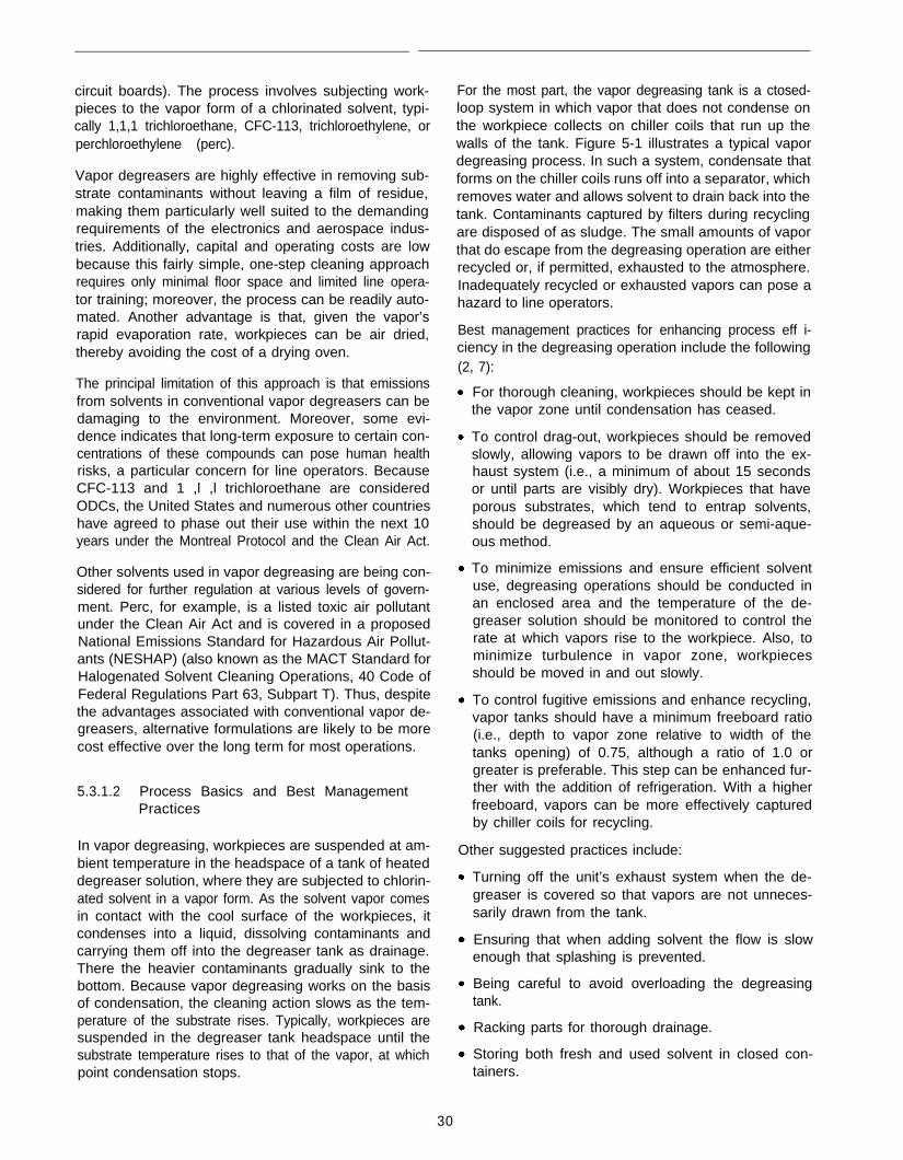
circuit boards). The process involves subjecting work-pieces to the vapor form of a chlorinated solvent, typi-cally 1,1,1 trichloroethane, CFC-113, trichloroethylene, orperchloroethylene (perc).
Vapor degreasers are highly effective in removing sub-strate contaminants without leaving a film of residue,making them particularly well suited to the demandingrequirements of the electronics and aerospace indus-tries. Additionally, capital and operating costs are lowbecause this fairly simple, one-step cleaning approachrequires only minimal floor space and limited line opera-tor training; moreover, the process can be readily auto-mated. Another advantage is that, given the vapor’srapid evaporation rate, workpieces can be air dried,thereby avoiding the cost of a drying oven.
The principal limitation of this approach is that emissionsfrom solvents in conventional vapor degreasers can bedamaging to the environment. Moreover, some evi-dence indicates that long-term exposure to certain con-centrations of these compounds can pose human healthrisks, a particular concern for line operators. BecauseCFC-113 and 1 ,l ,l trichloroethane are consideredODCs, the United States and numerous other countrieshave agreed to phase out their use within the next 10years under the Montreal Protocol and the Clean Air Act.
Other solvents used in vapor degreasing are being con-sidered for further regulation at various levels of govern-ment. Perc, for example, is a listed toxic air pollutantunder the Clean Air Act and is covered in a proposedNational Emissions Standard for Hazardous Air Pollut-ants (NESHAP) (also known as the MACT Standard forHalogenated Solvent Cleaning Operations, 40 Code ofFederal Regulations Part 63, Subpart T). Thus, despitethe advantages associated with conventional vapor de-greasers, alternative formulations are likely to be morecost effective over the long term for most operations.
5.3.1.2 Process Basics and Best ManagementPractices
In vapor degreasing, workpieces are suspended at am-bient temperature in the headspace of a tank of heateddegreaser solution, where they are subjected to chlorin-ated solvent in a vapor form. As the solvent vapor comesin contact with the cool surface of the workpieces, itcondenses into a liquid, dissolving contaminants andcarrying them off into the degreaser tank as drainage.There the heavier contaminants gradually sink to thebottom. Because vapor degreasing works on the basisof condensation, the cleaning action slows as the tem-perature of the substrate rises. Typically, workpieces aresuspended in the degreaser tank headspace until thesubstrate temperature rises to that of the vapor, at whichpoint condensation stops.
For the most part, the vapor degreasing tank is a ctosed-loop system in which vapor that does not condense onthe workpiece collects on chiller coils that run up thewalls of the tank. Figure 5-1 illustrates a typical vapordegreasing process. In such a system, condensate thatforms on the chiller coils runs off into a separator, whichremoves water and allows solvent to drain back into thetank. Contaminants captured by filters during recyclingare disposed of as sludge. The small amounts of vaporthat do escape from the degreasing operation are eitherrecycled or, if permitted, exhausted to the atmosphere.Inadequately recycled or exhausted vapors can pose ahazard to line operators.
Best management practices for enhancing process eff i-ciency in the degreasing operation include the following(2, 7):
For thorough cleaning, workpieces should be kept inthe vapor zone until condensation has ceased.
To control drag-out, workpieces should be removedslowly, allowing vapors to be drawn off into the ex-haust system (i.e., a minimum of about 15 secondsor until parts are visibly dry). Workpieces that haveporous substrates, which tend to entrap solvents,should be degreased by an aqueous or semi-aque-ous method.
To minimize emissions and ensure efficient solventuse, degreasing operations should be conducted inan enclosed area and the temperature of the de-greaser solution should be monitored to control therate at which vapors rise to the workpiece. Also, tominimize turbulence in vapor zone, workpiecesshould be moved in and out slowly.
To control fugitive emissions and enhance recycling,vapor tanks should have a minimum freeboard ratio(i.e., depth to vapor zone relative to width of thetanks opening) of 0.75, although a ratio of 1.0 orgreater is preferable. This step can be enhanced fur-ther with the addition of refrigeration. With a higherfreeboard, vapors can be more effectively capturedby chiller coils for recycling.
Other suggested practices include:
Turning off the unit’s exhaust system when the de-greaser is covered so that vapors are not unneces-sarily drawn from the tank.
Ensuring that when adding solvent the flow is slowenough that splashing is prevented.
Being careful to avoid overloading the degreasingtank.
Racking parts for thorough drainage.
Storing both fresh and used solvent in closed con-tainers.
30
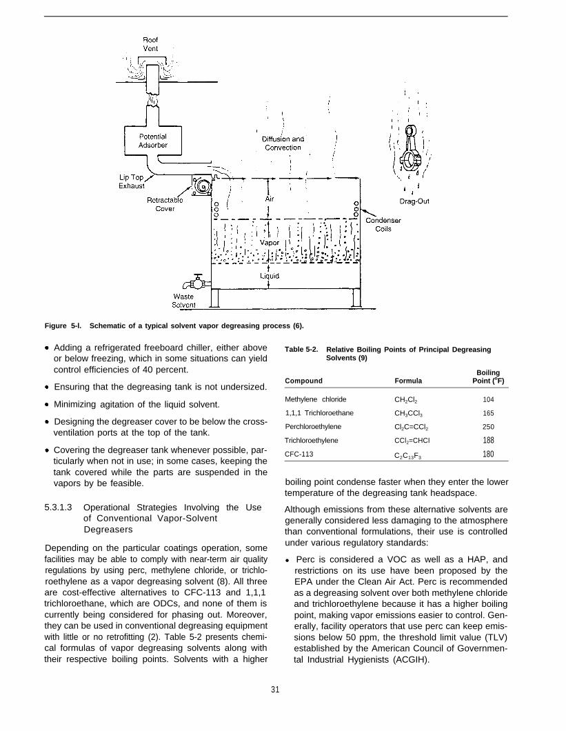
Figure 5-l. Schematic of a typical solvent vapor degreasing process (6).
Adding a refrigerated freeboard chiller, either aboveor below freezing, which in some situations can yieldcontrol efficiencies of 40 percent.
Ensuring that the degreasing tank is not undersized.
Minimizing agitation of the liquid solvent.
Designing the degreaser cover to be below the cross-ventilation ports at the top of the tank.
Covering the degreaser tank whenever possible, par-ticularly when not in use; in some cases, keeping thetank covered while the parts are suspended in thevapors by be feasible.
5.3.1.3 Operational Strategies Involving the Useof Conventional Vapor-SolventDegreasers
Depending on the particular coatings operation, somefacilities may be able to comply with near-term air qualityregulations by using perc, methylene chloride, or trichlo-roethylene as a vapor degreasing solvent (8). All threeare cost-effective alternatives to CFC-113 and 1,1,1trichloroethane, which are ODCs, and none of them iscurrently being considered for phasing out. Moreover,they can be used in conventional degreasing equipmentwith little or no retrofitting (2). Table 5-2 presents chemi-cal formulas of vapor degreasing solvents along withtheir respective boiling points. Solvents with a higher
Table 5-2. Relative Boiling Points of Principal DegreasingSolvents (9)
BoilingCompound Formula Point (oF)
Methylene chloride CH2Cl2 104
1,1,1 Trichloroethane CH3CCl3 165
Perchloroethylene Cl2C=CCl2 250
Trichloroethylene CCl2=CHCI 188
CFC-113 C2C13F3 180
boiling point condense faster when they enter the lowertemperature of the degreasing tank headspace.
Although emissions from these alternative solvents aregenerally considered less damaging to the atmospherethan conventional formulations, their use is controlledunder various regulatory standards:
l Perc is considered a VOC as well as a HAP, andrestrictions on its use have been proposed by theEPA under the Clean Air Act. Perc is recommendedas a degreasing solvent over both methylene chlorideand trichloroethylene because it has a higher boilingpoint, making vapor emissions easier to control. Gen-erally, facility operators that use perc can keep emis-sions below 50 ppm, the threshold limit value (TLV)established by the American Council of Governmen-tal Industrial Hygienists (ACGIH).
31

l Methylene chloride, a suspected carcinogen, is regu-lated as a HAP under the Clean Air Act. Although notconsidered a VOC due to its negligible photochemicalreactivities, OSHA is seeking to lower its permissibleexposure level (PEL) from 500 ppm to 25 ppm. More-over, methylene chloride is covered along with percby EPA’s proposed NESHAP for solvent degreasing.
l Trichloroethylene is regulated as a VOC and a HAPunder the Clean Air Act.
More generally, if the state permitting authority deter-mines that an operation submitting an application forone of these solvents is likely to exceed federal or stateTLVs, the facility may be considered to come within the“major source” category under Titles III and V of theClean Air Act.2 Air quality control requirements for facili-ties in this category can increase the cost of operation.For instance, a major source facility might be requiredto install emission abatement devices such as thermalor catalytic oxidizers, zeolite adsorbers, or biofilters.Thus, facility operators should perform a thoroughanalysis of the “potential to emit,” as defined in Titles IIIand V, before switching to one of these alternatives.
Some of the available alternative degreasers include:
l HCFC-141b: Although this solvent, manufactured byAllied Signal, is a VOC, it has a low ozone-depletingpotential. Nonetheless, it can only be used in clean-ing operations through 1996 and only at facilitieswhere it has been in use since late in 1994. Completephaseout of the solvent is scheduled for 2002.
l HCFC-225: This solvent, manufactured by AGAChemicals, has an even lower ozone-depleting po-tential than HCFC-141 b and can be used until 2020,at which time it will be banned from use.
l HCFC-123: This solvent, manufactured by DuPont,appears to offer low toxicity; however, it is not in wideuse.
Additional possible interim strategies include:
Use HFCs for vapor degreasing and drying until De-cember 31, 1999, after which the HFCs must bereplaced.
Use a relatively nonvolatile solvent for cleaning andan HFC solvent for drying until December 31, 1999,after which the HFCs must be replaced.
The best long-term strategy may be to switch to a de-greaser that does not emit HAPS. Numerous aqueous
2 Under Title Ill, a major source is one that has the potential to emitgreater than 10 tons per year (tpy) of a single HAP or greater than25 tpy of more than one HAP. Under Title V, a major source is onethat has the potential to emit greater than 100 tpy of VOCs, greaterthan 10 tpy of a single HAP, or greater than 25 tpy of more than oneHAP. Under both Title Ill and V, other conditions also can apply toqualify a source as “major.”
and semi-aqueous degreasers are currently available,and others are in development. Although for certainhigh-value processes the effectiveness of present for-mulations as replacements for solvent degreasers hasyet to be demonstrated, many facility operators are likelyto find them well suited to their needs. One limitation isthat aqueous degreasers generally require a multiple-step process (i.e., cleaning then rinsing) followed bydrying in a high-temperature oven. As a result, capitalcosts can be higher. Aqueous and semi-aqueous formu-lations are discussed in detail in Section 5.4.
Also in development are HFCs that neither deplete theozone nor are considered to be VOCs due to theirnegligible photochemical reactivity to the atmosphere.The challenge for researchers will be to formulate adegreaser that has both good substrate cleaning andthorough drying characteristics. Some of these alterna-tive solvents are expected to be available before the endof the decade.
One encouraging development concerns perfluorinatedcarbon compounds (PFCs) that contain only carbon andfluorine and are considered to be neither VOCs (smogformers) nor ODCs. These compounds may be devel-oped for use as alternative drying agents. PFCs aremore volatile than l,l,l trichloroethane and CFC-113and thus would serve as an ideal replacement for op-erations in which fast drying is mandatory (e.g., forworkpieces with complex geometries). Although thereare concerns that these compounds contribute to globalwarming, EPA has approved them for the SignificantNew Alternatives Program (SNAP) 1.
More generally, if facility operators follow the proposedNESHAP for halogenated solvents, they should be ableto run their processes well within OSHA requirementsand easily meet permit limits.
5.3.2 Degreasing With Liquid Solvent (ColdCleaning and Solvent Wiping)
5.3.2.1 Introduction
Solvents in liquid form are widely used for degreasingworkpieces before applying a primer-topcoat system.This method-often called cold cleaning because thesolvent is unheated, in contrast to vapor degreasing-involves bringing workpieces into direct contact with asolvent, such as methyl isobutyl ketone (MIBK), methylethyl ketone (MEK), or 1,1,1 trichloroethane (Table 5-3).
The great advantage of degreasers in liquid form is theirversatility. They can be used to clean entire workpiecesby immersion or spray washing (i.e., cold cleaning), forinstance, or to clean selected areas of a componentusing rags, brushes, or cotton swabs (i.e., solvent wip-ing). Figure 5-2 illustrates a typical cold-solvent cleaningprocess.
32
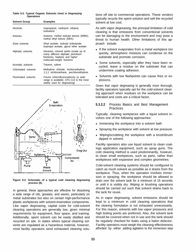
Table 5-3. Typical Organic Solvents Used in DegreasingOperations
Solvent Group
Alcohols
Examples
Isopropanol, methanol, ethanol,isobutanol
Ketones Acetone, methyl isobutyl ketone (MIBK),methyl ethyl ketone (MEK)
Ester solvents Ethyl acetate, isobutyl isobutyrate,isopropyl acetate, glycol ether acetate
Aliphatic solvents Hexanes, mineral spirits (made up ofmany different aliphatic petroleumfractions), heptane and highermolecular-weight fractions
Aromatic solvents
Chlorinated solvents
Toluene, xylene
Methylene chloride, trichloroethylene,1,1,1 trichloroethane, perchloroethylene
Fluorinated solvents Freons (chlorofluorocarbons) (a widerange is available; CFC-113 is the mostwidely used for degreasing)
Figure 5-2. Schematic of a typical cold cleaning degreasingprocess (6).
In general, these approaches are effective for dissolvinga wide range of oils, greases, and waxes, particularly onmetal substrates but also on certain high-performanceplastic workpieces with solvent-insensitive components.Like vapor degreasing, capital costs for cold-solventcleaning operations are generally low, given minimalrequirements for equipment, floor space, and training.Additionally, spent solvent can be easily distilled andrecycled on site. In states where typical cleaning sol-vents are regulated as a hazardous material, however,most facility operators send exhausted cleaning solu-
tions off site to commercial operations. These vendorstypically recycle the spent solution and sell the recycledsolvent at low cost.
As with vapor degreasing, the principal limitation of coldcleaning is that emissions from conventional soIventscan be damaging to the environment and may pose athreat to human health. Other limitations of this ap-proach include:
l If the solvent evaporates from a metal workpiece tooquickly, atmospheric moisture can condense on thesubstrate and promote corrosion.
l Some solvents, especially after they have been re-cycled, leave a residue on the substrate that canundermine coating adhesion.
l Solvents with low flashpoints can cause fires or ex-plosions.
Given that vapor degreasing is generally more thorough,facility operators typically opt for the cold-solvent cleaning approach when residues on the workpiece can betolerated and costs are a critical factor.
5.3.2.2 Process Basics and Best ManagementPractices
Typically, cleaning workpieces with a liquid solvent in-volves one of the following approaches:
l Immersing the workpiece into a solvent bath
l Spraying the workpiece with solvent at low pressure.
l Wiping/scrubbing the workpiece with a brush/brushdipped in solvent.
Facility operators also use liquid solvent to clean coat-ings application equipment, such as spray guns. Thecold cleaning method is used predominantly, however,to clean small workpieces, such as parts, rather thanworkpieces with expansive and complex geometries.
Cold-solvent cleaning systems should be configured tocatch as much solvent as possible as it drains from theworkpiece. Thus, when the operation involves immer-sion or spraying, the workpiece should be allowed todrain over the solvent tank for a minimum of 15 secondsor until it is visibly dry. Wiping or brushing operationsshould be carried out such that solvent drains back tothe tank for reuse.
As in vapor degreasing, solvent emissions should bekept to a minimum in cold cleaning operations thatthe cleaning formulation is not exhausted unnecessarily.For this reason, solvents with low vapor pressures andhigh boiling points are preferred. Also, the solvent tankshould be covered when not in use and the tank shouldbe regularly checked for leaks using a halon detector.Facility operators must weigh the cleaning effectivenessafforded by either adding agitation to the immersion step
33
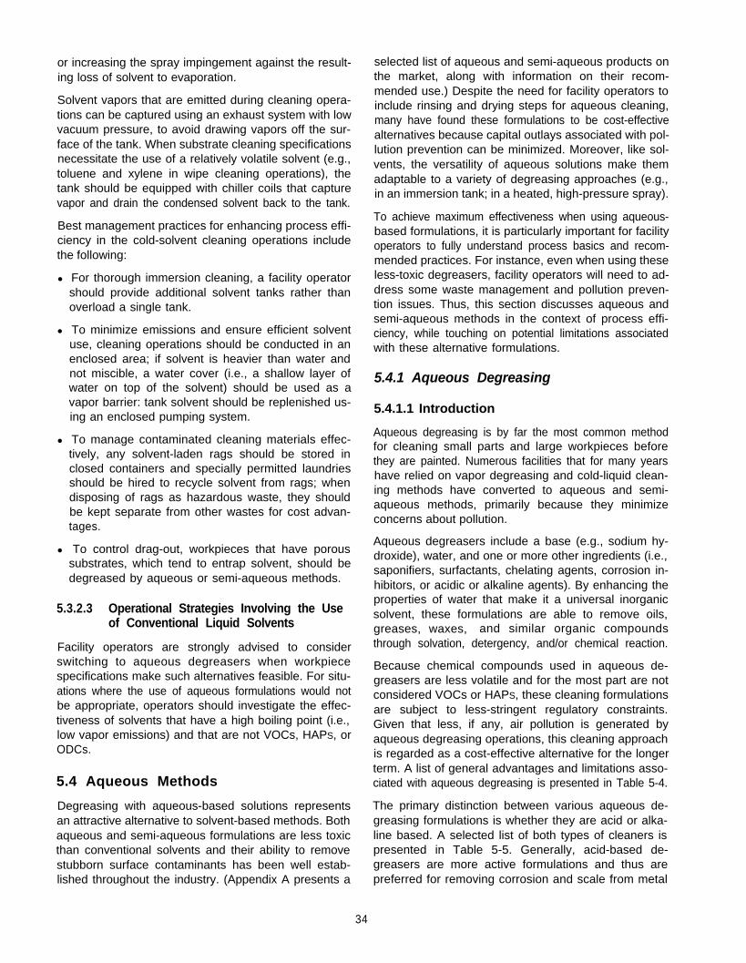
or increasing the spray impingement against the result-ing loss of solvent to evaporation.
Solvent vapors that are emitted during cleaning opera-tions can be captured using an exhaust system with lowvacuum pressure, to avoid drawing vapors off the sur-face of the tank. When substrate cleaning specificationsnecessitate the use of a relatively volatile solvent (e.g.,toluene and xylene in wipe cleaning operations), thetank should be equipped with chiller coils that capturevapor and drain the condensed solvent back to the tank.
Best management practices for enhancing process effi-ciency in the cold-solvent cleaning operations includethe following:
l For thorough immersion cleaning, a facility operatorshould provide additional solvent tanks rather thanoverload a single tank.
l To minimize emissions and ensure efficient solventuse, cleaning operations should be conducted in anenclosed area; if solvent is heavier than water andnot miscible, a water cover (i.e., a shallow layer ofwater on top of the solvent) should be used as avapor barrier: tank solvent should be replenished us-ing an enclosed pumping system.
l To manage contaminated cleaning materials effec-tively, any solvent-laden rags should be stored inclosed containers and specially permitted laundriesshould be hired to recycle solvent from rags; whendisposing of rags as hazardous waste, they shouldbe kept separate from other wastes for cost advan-tages.
l To control drag-out, workpieces that have poroussubstrates, which tend to entrap solvent, should bedegreased by aqueous or semi-aqueous methods.
5.3.2.3 Operational Strategies Involving the Useof Conventional Liquid Solvents
Facility operators are strongly advised to considerswitching to aqueous degreasers when workpiecespecifications make such alternatives feasible. For situ-ations where the use of aqueous formulations would notbe appropriate, operators should investigate the effec-tiveness of solvents that have a high boiling point (i.e.,low vapor emissions) and that are not VOCs, HAPS, orODCs.
5.4 Aqueous Methods
Degreasing with aqueous-based solutions representsan attractive alternative to solvent-based methods. Bothaqueous and semi-aqueous formulations are less toxicthan conventional solvents and their ability to removestubborn surface contaminants has been well estab-lished throughout the industry. (Appendix A presents a
selected list of aqueous and semi-aqueous products onthe market, along with information on their recom-mended use.) Despite the need for facility operators toinclude rinsing and drying steps for aqueous cleaning,many have found these formulations to be cost-effectivealternatives because capital outlays associated with pol-lution prevention can be minimized. Moreover, like sol-vents, the versatility of aqueous solutions make themadaptable to a variety of degreasing approaches (e.g.,in an immersion tank; in a heated, high-pressure spray).
To achieve maximum effectiveness when using aqueous-based formulations, it is particularly important for facilityoperators to fully understand process basics and recom-mended practices. For instance, even when using theseless-toxic degreasers, facility operators will need to ad-dress some waste management and pollution preven-tion issues. Thus, this section discusses aqueous andsemi-aqueous methods in the context of process effi-ciency, while touching on potential limitations associatedwith these alternative formulations.
5.4.1 Aqueous Degreasing
5.4.1.1 Introduction
Aqueous degreasing is by far the most common methodfor cleaning small parts and large workpieces beforethey are painted. Numerous facilities that for many yearshave relied on vapor degreasing and cold-liquid clean-ing methods have converted to aqueous and semi-aqueous methods, primarily because they minimizeconcerns about pollution.
Aqueous degreasers include a base (e.g., sodium hy-droxide), water, and one or more other ingredients (i.e.,saponifiers, surfactants, chelating agents, corrosion in-hibitors, or acidic or alkaline agents). By enhancing theproperties of water that make it a universal inorganicsolvent, these formulations are able to remove oils,greases, waxes, and similar organic compoundsthrough solvation, detergency, and/or chemical reaction.
Because chemical compounds used in aqueous de-greasers are less volatile and for the most part are notconsidered VOCs or HAPS, these cleaning formulationsare subject to less-stringent regulatory constraints.Given that less, if any, air pollution is generated byaqueous degreasing operations, this cleaning approachis regarded as a cost-effective alternative for the longerterm. A list of general advantages and limitations asso-ciated with aqueous degreasing is presented in Table 5-4.
The primary distinction between various aqueous de-greasing formulations is whether they are acid or alka-line based. A selected list of both types of cleaners ispresented in Table 5-5. Generally, acid-based de-greasers are more active formulations and thus arepreferred for removing corrosion and scale from metal
34

Table 5-4. Considerations for Aqueous Degreasing
Advantages Disadvantages
Does not emit solvent Requires more floor space thanvapors (VOCs, HAPS, or vapor degreasing or cold-solventODCs) into the air cleaning operations
Removes most contaminants Cannot be used to clean parts that(e.g., oils, greases, hydraulic are moisture sensitive (e.g.,fluids) and more stubborn assembled electronic components)contaminants (e.g., smut,metal fines) if agitation is Usually requires a dry-off oven,used which consumes energy; inadequate
drying can promote flash rustingCan be used in batch orcontinuous operations Large parts may be more difficult to
cleanWell suited to cleaningprocesses that will be Operator may need to experimentfollowed by a phosphate with various degreasing chemicals ifcoating stubborn deposits are not easily
removedA dry-off oven may not benecessary if the parts will be Poor rinsing can contribute to paintcoated with a water-borne failurescoating (e.g., electrocoating)
Additional quality control is requiredMonitoring of chemicals is (in contrast to vapor degreasing) ifnot complicated; process surfaces must be especially cleanincludes a pH check andcontrol of temperature, Water may collect in channels andprocessing time, agitation in pockets, from where it may notthe form of air sparging (for thoroughly evaporateimmersion tanks); goodimpingement (for tunnel Water and degreaser may getsystems) between overlapping joints on certain
workpieces and later seep out andCan be used for all types of mar the coating if inadequate ovenparts, regardless of whether drying is carried outthey are solvent sensitive
Metal surfaces, which are slightlyalkaline after degreasing, must beneutralized with an acidic solution(e.g., a phosphate coating) beforepaint can be applied
Wastewater must be treated before itcan be disposed
Table 5-5. Selected Aqueous Degreasers (1)
l Ammonium hydroxide, potassium hydroxide, sodium hydroxide
l Diethylene glycol monobutyl ether
l Dodecanedionic acid
l Ethylenediaminetetra-acetic acid (EDTA) and its tetrasodium salt
l Monoethanolamine, diethanolamine, triethanolamine
l Borax
l Sodium carbonate
l Sodium gluconate
l Sodium silicate, sodium metasilicate
l Sodium tripolyphosphate, trisodium phosphate, tetrasodiumphosphate, tetrapotassium pyrophosphate
l Sodium xylene sulfonate
l Water (tap, deionized, steam)
35
workpieces. In contrast, because they are somewhatmilder, alkaline formulations are recommended forcleaning plastics as well as certain metal substrates,such as aluminum, particularly when the corrosivity ofacid degreasers is a concern. Alkaline solutions caneffectively remove such contaminants as oil, grease,and waxy films. Because both types of formulations arecorrosive, cleaning system operators must take precau-tions, such as wearing protective equipment, to avoidsustaining chemical burns.
Although acid degreasing is more effective for certainsubstrates, the corrosivity of acid compounds necessi-tates the use of more expensive containment equipmentand additional maintenance. For instance, to preventcorrosion of immersion tanks, they must be lined withrubber or plastic or made of stainless steel. Indeed,inhibitors are often added to the degreasing solution toprevent the corrosion of tanks. These formulations alsosolubilize heavy metals from substrates and etch steel,thus generating more sludge that must be disposed ofas a hazardous waste. Moreover, because acid cleanerscan cause hydrogen embrittlement of the substrate, thisapproach should not be used for workpieces made ofhigh-tensile steel. Finally, without thorough rinsing or theincorporation of inhibitors, acids in the cleaning solutioncan promote corrosion of the finished workpiece.
Alkaline formulations are not without their limitations,however. For example, trace alkalinity may be difficult torinse from the workpiece. Also, certain substrates, par-ticularly on some electrical components, may be subjectto corrosion under alkaline, rather than acidic, conditions.
Aqueous degreasing generally allows facility operatorsto avoid costs associated with pollution prevention, par-ticularly air emissions control devices. Capital equip-ment and process requirements, however, can add tooperation costs. In contrast to one-step solvent ap-proaches, aqueous degreasing involves at least a two-step process in which acidic or alkaline residues arerinsed from the workpiece following degreasing. Moreoften, however, operators use a three-step system thatincludes drying the rinsed workpiece in an oven beforeapplying paint or a pretreatment coating. (For detaileddiscussions about phosphating and rinsing, see Chap-ters 6 and 7, respectively.)
5.4.1.2 Process Basics and Best ManagementPractices
Typically, aqueous degreasing operations involve sub-jecting workpieces to the cleaning solution eitherthrough immersion or pressure spraying. The most basicprocess includes a cleaning step followed by rinsing thatadjusts the pH level of the substrate by removing acidicor alkaline residues. The system should be configuredto allow the degreasing solution to thoroughly drain fromthe workpiece, thus minimizing drag-out into the rinsing
bath. Proper draining of workpieces also facilitates effi-cient use of the cleaning solution. Following immersion,a workpiece should be allowed to drain while suspendedover the tank: in spray operations, a containment systemshould be used to channel drainage back to the feedsource. Both immersion and spraying lend themselvesto automation.
An advantage of aqueous degreasing over the liquidsolvent method is that agitation can be readily added tothe immersion process, given that the cleaning solutionis less volatile and therefore less likely to evaporate.Agitation is particularly recommended for cleaning eitherworkpieces with complex geometries (e.g., with re-cesses or threaded sections) or numerous small partsat one time. The immersion approach in general is ad-vantageous when floor space is limited.
Some facilities enhance the effectiveness of conventionalspray cleaning operations by using either super-heatedsteam or high-pressure hot water. Both approaches,loosely referred to as steam cleaning, involve a pumpingsystem that mixes heated water with the cleaning solu-tion and delivers it via a hose to the spray wand. Ingeneral, steam cleaning is used on workpieces that aretoo large to fit in an immersion tank or to pass througha conveyorized spray system. The major disadvantageof such cleaning methods is that they consume largeamounts of water, which must be treated before beingdischarged to a publicly owned treatment works.
For true steam cleaning, water is typically heated toapproximately 230°F (i.e., well above the boiling point ofwater’) and the super heated steam is sprayed at apressure of 50 to 150 psi. Steam can be effective forremoving particularly stubborn contaminants. This ap-proach also is recommended for minimizing water us-age and promoting rapid drying of the substrate. Theprincipal disadvantage of this approach is that line op-erators can be scalded easily by super heated steam, inpart because it is nearly invisible as it comes off thespray wand.
High-pressure hot water spraying reduces the likelihoodof worker injury because the water is heated to a tem-perature below the boiling point and sprayed at pres-sures ranging from 50 to 100 psi. Despite the lowertemperature of the water, this approach, which includesuse of a soap detergent typically drawn from a 55-gallondrum, can be highly effective for removing many of thesame deep-seated contaminants from a substrate. (Theappropriate concentration of the detergent should bebased onI the manufacturer’s recommendation.) Addi-tionally a system can be set up in which a single spraywand is used to clean and rinse a workpiece and then,for a metal substrate, apply a mild phosphate coating.In such a system, the process operator can control avalve that shuts off the degreaser formulation feed andturns on the phosphate feed. As with the degreaser, the
phosphate typically is siphoned from a 55-gallon drum.After applying a low-concentration phosphoric acid (e.g.,2 oz/gal) to the workpiece and allowing for a 45 to 60second contact time, the operator can give the piece afinal rinse with clean, hot water.
The following factors apply with this approach to phos-phating (see also Chapter 6 for an extensive discussionof phosphate deposition considerations):
l Phosphoric acid should be syphoned directly to thewand rather than to the hot water heater, where itmight encourage corrosion of the heating coils.
l The light phosphate coating deposited with thismethod can provide only short-term protection (sev-eral hours) against flash rusting; it should not becompared with conventional iron or zinc phosphates,which provide conversion coatings with significantlygreater corrosion resistance.
l Despite deposition of the phosphate coating, theworkpiece should be dried quickly to avoid potentialflash rusting, especially on workpieces with complexgeometries.
l Whereas blow drying is recommended, the processoperator should ensure that moisture or oil is notconveyed to the workpiece with the ambient air com-ing from the compressor. The blower system’s oil andmoisture traps should be checked frequently.
l Because phosphate cannot form over scale or rust,in some cases the deposited coating will provide littlecorrosion protection for hot rolled steel with such con-taminants on the substrate. The acid will neutralize,however, any alkalinity that may remain on the sub-strate after alkaline degreasing-a critical parameterfor adhesion of the primer coat.
Regardless of the aqueous cleaning approach used,such operations generate wastewater that must betreated before being exhausted to a publicly ownedtreatment works. Generally, spent washwater is dumpedor drained into a settling tank. Oil and grease that riseto the top are skimmed off and usually either 1) sent offsite to be blended into a fuels that can be thermallyoxidized or 2) disposed of as a liquid hazardous waste.Contaminants pumped out from the bottom often arepassed through a filter press, dried into a cake, and thendisposed of as a solid hazardous or nonhazardouswaste, depending on the characteristics. In some cases,the dried sludge is used as an inert filler in other opera-tions. The remaining water is treated for pH adjustmentand then either discharged to the treatment works ordumped into a shallow holding pond, where it is allowedto evaporate. Many large facilities have begun recyclingall of their process water to the cleaning operation fol-lowing onsite treatment. In this way, many such facilitiesare seeking to achieve closed-loop operations.
36
Best management practices for enhancing process effi-ciency in the aqueous degreasing operation include thefollowing:
l For thorough cleaning:
- Experiment with different aqueous degreaser prod-ucts and contact several vendors to identify theformulation best suited to particular workpieces.
- Test the entire range of degreasers recommendedby a vendor because solution formulation and tem-perature can alter cleaning efficiency.
- Ensure that batches of parts immersed in the de-greaser are properly positioned to avoid overlapand to minimize drag-out.
l For cost effectiveness:
- Raise the temperature of the degreasing solutionand the rinse water to avoid the expense associ-ated with removing flash rusting, especially in op-erations that do not include a drying oven. (Thefacility operator should keep in mind, however, thatheating the degreaser will add to energy costssomewhat.)
- Compare costs of powdered and liquid degreasingformulations.
l For process efficiency:
- Purchase degreaser and phosphate formulationsfrom the same vendor to avoid compatibilityproblems.
5.4.1.3 Process Variations
Two-Step Process
A two-step aqueous degreasing process involves clean-ing and then rinsing the workpiece, usually with tapwater. In a paints and coatings operation, this basicsystem for degreasing might be used, for example, be-tween application of the primer and the finish coat. Sucha process might be used when primed workpieces willbe stored outdoors for weeks or months before being usedin the assembly of a finished product. Degreasing wouldbe performed immediately before application of the top-coat to remove any fingerprints and general grime, in-dustrial oils, or hydraulic fluids deposited on workpiecesurfaces. After degreasing, the workpieces then couldbe left to dry in the ambient environment, particularlypieces that incorporate electronic components or heat-sensitive materials. Flash rusting is not a concern at thisstage because the piece has already received its primercoat. Alternatively, the workpieces may be dried usingair knives (i.e., targeted jets of warm air) or by subjectingthe pieces to blasts of clean, dry compressed air.
Contaminants in tap water, however, can undermine thelong-term corrosion-resistance of a finished piece. Thus,a single tap-water rinse is recommended only for low-
37
value products in price-sensitive markets or productsthat will not be used in humid or corrosive environments.
Three-Step Process
In a three-step process, the degreaser is followed by atleast one tap-water rinse and then rinsing with deionizedwater. The use of deionized water is recommendedwhen the workpiece will undergo phosphating after de-greasing and a high-quality phosphate coating must beachieved to ensure a high-value finished piece.
If a high-value workpiece will not receive phosphatingpretreatment, the piece might need to be dried, followingrinsing, in an oven at a temperature ranging from 260o
to 400°F. The higher end of the temperature range fordry-off is not recommended, however, for alloys thatmight undergo a phase transformation, for machinedparts that must meet especially high tolerances, or forcomponents that include heat-sensitive materials. Otherconsiderations include the cost of firing the drying ovenat sustained high temperatures and the time required forworkpieces to cool, especially heavy castings, beforebeing moved along in the process.
Four- and Five-Step Processes
Operations applying a primer-topcoat system to high-value workpieces that must be thoroughly cleaned be-fore a phosphate coating is applied often provideadditional rinse steps at the degreasing stage. For ex-ample, operations in the automotive and appliance in-dustries typically rinse workpieces in one or two bathsof deionized water after the tap-water rinse step. Alongwith ensuring proper adhesion of coatings by minimizingsurface contaminants, these additional rinse steps alsoextend the useful life of conversion coating baths byminimizing degreaser drag-out. For superior corrosionresistance, the conversion coating must be deposited ona slightly acidic surface (i.e., in the range of 5 to 6 pH).(For a detailed discussion of rinsing operations, seeChapter 7.)
5.4.2 Semi-aqueous Degreasing
5.4.2.1 Introduction
Semi-aqueous degreasers represent a middle groundbetween the use of solvent-based and aqueous ap-proaches. They are more effective than strictly aqueousformulations for removing heavier grease, wax, andeven tar from a variety of substrates (i.e., metal, ce-ramic, plastic, and elastomer); however, because theseformulations include volatile ingredients-albeit with lowvapor pressures and high boiling points-they are regu-lated as VOCs, HAPS, or ODCs. Semi-aqueous mix-tures are based on organic compounds, such asterpenes and alcohols, and thus are somewhat lessthreatening to the environment and human health than

most conventional solvent degreasers. The cleaningmechanism for semi-aqueous degreasers is essentiallythe same as for aqueous degreasers. Table 5-6 liststypical organic constituents used in semi-aqueous de-greasers.
An additional advantage of semi-aqueous over solventdegreasers is that they generally have a higher flash-point and lower volatility than organic solvents; thus,they are less prone to combustion and evaporation,making them applicable in both spray and immersionprocesses. Moreover, because such formulations tendto be characterized by low surface tension, they areparticularly effective on workpieces with surface fea-tures that are difficult to clean, such as small holes andcrevices.
A principal limitation of semi-aqueous degreasers is thatthey are highly flammable when in a concentrated gase-ous form, especially formulations based on terpenes. Forthis reason, they should never be heated above 90°F.Flammability can be minimized, however, by formulatingor using them in their emulsion form. Additionally, certainformulations can cause plastics and elastomers to swell.
5.4.2.2 Process Basics and Best ManagementPractices
Degreasing operations using semi-aqueous formula-tions are conducted in the same way as aqueous clean-ing. The basic process involves two steps-degreasing,
Table 5-6. Typical Organic Constituents in Semi-aqueousDegreasers (3)
Constituent Comment
Terpenes
Esters
Glycol ethers
N-methyl-2-pyrro-lidone (C5H9NO)
Ethyl lactate
Derived from citrus and pine oils; can beformulated into emulsions; new formulationsraise flashpoint to >144OF providing cleaningeffectiveness and reducing danger of fire orexplosion; effective at low temperatures;often can be recycled
Most common are aliphatic mono esters(primarily alkyl acetates) and di-basic esters(DBEs); can be used cold or heated;favorable solvent properties but poorsolubility in water; flashpoint usually >200oF;can be slow drying
Generally divided between e- and p-series,with neither considered a HAP; favorablesolvent properties and effective as emulsionin water; can remove polar and nonpolarcontaminants; easy to recycle; flashpointusually to >200°F
High solvency and effective on manycontaminants; completely soluble in waterand other liquids; can be used cold orheated: flashpoint is approximately to 199°F
Can be used as for cold-liquid degreasing; aVOC, but not considered a HAP or an ODC;has a favorable evaporation rate
either by immersion or spraying, followed by a tap-waterrinse to remove residues.
For a more extensive discussion of semi-aqueous de-greasers, see EPA’s Guide to Cleaner Technologies:Alternatives to Chlorinated Solvents for Cleaning andDegreasing (3) (see also Reference 5).
5.5 Case Examples
5.5.1 Frame Manufacturer
A large manufacturer purchased oil-free and pickledsteel for fabricating frames to be used in heavy machin-ery. Despite the higher cost, managers believed theywould be able to produce a better and longer-lastingproduct. A few months after switching to the treatedsteel, however, they experienced a spate of catastrophicpaint failures. It appeared that the frames would have tobe recalled and then stripped, cleaned, and repainted.
In the original process, after fabrication the frames weremoved into a washing room where all workpiece sur-faces were thoroughly cleaned with a high-pressurehot-water degreaser using a wand. Because the frameswere long and wide, the left side was cleaned before theright. In the first pass along the left side, the hot waterincorporated a soap solution. In the second pass, theframe was rinsed with municipal tap water at ambienttemperature. The line operator then repeated the proc-ess on the right side of the frame. After the entire clean-ing operation was completed, the frame was storedoutside where the surfaces were left to dry at ambienttemperature.
Due to the size of the frames, the entire degreasingprocess took 1 to 1.5 hours. By this time, the entireworkpiece was covered in flash rust. The productionmanager, unaware of the situation, allowed the primerand topcoat to be applied over the rusted surfaces. Onlyafter several frames were rejected because of cata-strophic failures in the field did managers call in a con-sultant to investigate the cause of the problem. Theyfound that several poor practices contributed to the paintfailures:
During the first pass along the right side of the frame,the fine overspray of detergent solution from thespray wand was contaminating the already-cleanedsurfaces on the left side.
Because the first stage was hot (approximately180oF), the detergent solution from the first stageevaporated from the frames, leaving a residue of al-kaline soap on the surface.
The frames were rinsed with municipal tap water thathad a high concentration of minerals (i.e., dissolvedsalts). When the water evaporated, the minerals
38

I
remained on the surface and thus were available topromote corrosion under the topcoat of paint.
l Because the original milling oils had been removedfrom the steel surfaces during the degreasing opera-tion, the metal was more sensitive to flash rusting.This was aggravated by the slow evaporation rate ofwater at ambient temperatures.
The managers were advised to abrasive-blast clean themetal surfaces to a near-white finish (see Chapter 8)and then apply a corrosion-resistant primer within 4hours. The company, however, could not justify the ex-pense of installing a blast cleaning room. Instead, themanagers made the following changes to their process:
Two workers were assigned to perform the degreas-ing operation so that the metal surfaces at the frontend of the frame would not dry while the back endwas still being degreased.
Surfaces were kept wet until the final rinse had beenaccomplished.
Deionized rinse water was used to avoid contamina-tion by dissolved salts in the municipal tap water.
The deionized water was heated to approximately180°F to accelerate the drying process and thusavoid the need for a drying oven.
To minimize water usage and the disposal of excesscontaminated water, the rinse stage was recycledthrough an ion exchange resin in the deionized watergenerator.
The company’s production off ice rescheduled workso that the frames could be moved directly from thewashing room into the primer spray booth. (Cleanedframes were not stored outside unless they had beenprimed.)
The frames that were rejected due to flash-rusting un-derwent paint stripping operations and then were re-painted. The cost of this approach was quite highbecause contractors were required to disassemble theend-products to process the failed frames.
5.5.2 Military Contractor
A large military contractor in the Midwest was usingapproximately 250,000 pounds per year of l,l,ltrichloroethane to degrease primarily aluminum partsprior to welding. The company was participating in EPA’s33/50 program, which encourages a use reduction forselected hazardous chemicals by 33 percent by the endof 1992 and a further 50 percent by the end of 1995.Thus, managers decided to totally eliminate their use of1 ,l ,l trichloroethane by installing an aqueous degreas-ing washing cabinet.
Given the vast number of part configurations needing tobe cleaned, a highly sophisticated system was pur-chased. The cabinet included a rotating table, high-pres-sure spray nozzles, the ability to add an inhibitor to therinse water, and the option to add more than one rinse,depending on the complexity and configuration of theparts. The system is a closed loop, ensuring that thelarge amount of water used is treated in an ultrafiltrationunit and then recycled.
Military specifications needed to be followed in themanufacture of the end-product, requiring that the con-tractor obtain approval before changing the degreasingprocess. The military client, however, also was inter-ested in eliminating the use of 1,1,1 trichloroethane andreadily approved the change.
5.5.3 Lift Truck Manufacturer
A lift truck manufacturer with a solvent-based degreas-ing operation for cleaning cutting oils and metal fines,primarily from aluminum parts, decided to switch to anaqueous degreaser. The incentive, in part, was concernabout exposure of line operators to harmful emissions.
The principal solvent being used by the company forvapor and cold cleaning was 1,1,1 trichloroethane. Be-fore swrtching degreasing formulations, the companytested approximately 30 different aqueous degreasers,comparing their effectiveness to the 1,1,1 trichloroethane.Eventually, the company identified an aqueous degreaserthat was more effective for removing stubborn surfacecontaminants than the 1,1,1 trichloroethane.
When the company evaluated their cleaning operationsfor both small par!s (primarily screw machine parts) andlarger workpIeces with complex geometries, managersfound that both tj/pes of workpieces could be effectivelycleaned by immersion in a tank of agitated aqueousdegreaser. For the smaller parts, an additional advan-tage of the process change was that it allowed thecompany to combine degreasing with the removal ofburrs as a result of bath agitation. For the larger parts,managers were able to identify a degreaser that wouldbe effective on the aluminum workpieces as well as theoccasional copper and cast iron pieces. Following de-greasing, the workpieces were rinsed in a solution con-taining a corrosion inhibitor and then were blown dry.
Conversion to aqueous degreasing reportedly saved thecompany about $102,000 per year, at the same time thattoxic emissions were essentially eliminated. The major-ity of savings resulted from more efficient use of thecleaning formulation, given that a batch of aqueousdegreaser includes only 5 to 10 percent cleaning solu-tion, with the balance being water.
Over the past decade, EPA and state officials havebeen encouraging companies to evaluate their proc-esses and consider switching to degreasing approaches
39
that generate less pollution. As a result, many compa-nies have discovered that they have been clinging to oldand inefficient practices. By updating their operations,many realized significant process efficiencies and evenenhanced the quality of their finished products.
This case example emphasizes the importance of test-ing numerous degreasers from more than one vendorbefore making a change. Because no universal de-greaser exists-solvent or aqueous-that will remove allsurface contaminants, often a degreaser must bematched to the specific operation. Thus, when switchingdegreaser formulations, a facility operator should al-ways allow sufficient time to test available products.
5.6 References
1. Foecke, T. 1993. Principles of cleaning. Teleconference on water-based alternatives to solvent cleaning. Presented by the ClevelandAdvanced Manufacturing Program, February 11. Sponsored by theGreat Lakes Protection Fund and the Joyce Fund, Cleveland, OH.
2.
3.
4.
5.
6.
Burch, D.J. 1993. Chlorinated solvent vapor degreasing: The clockis ticking. Teleconference on water-based alternatives to solventcleaning. Presented by the Cleveland Advanced ManufacturingProgram, February 11. Sponsored by the Great Lakes ProtectionFund and the Joyce Fund, Cleveland, OH.
U.S. EPA. 1994. Guide to cleaner technologies: Alternatives tochlorinated solvents for cleaning and degreasing. Office or Re-search and Development, Washington, DC. EPA/625/R-93/016.
U.S. EPA. 1994. Guide to cleaner technologies: Cleaning anddegreasing process changes. Office or Research and Develop-ment, Washington, DC. EPA/625/R-93/017.
Cleveland Advanced Manufacturing Program (CAMP). 1993.Water-based alternatives to solvent cleaning. Teleconference onwater-based alternatives to solvent cleaning. Presented by theCAMP, February 11. Sponsored by the Great Lakes ProtectionFund and the Joyce Fund, Cleveland, OH.
U.S. EPA. 1985. Stationary point and area sources. In: Compila-tion of Emission Factors, 4th ed., vol.1. EPA/AP-42 (September).
Joseph, R. 1992. Pollution prevention for paints and coatings fa-cilities: Training Program. Saratoga, CA: Ron Joseph & Associates.
Durkee, II, J.B. 1994. The parts cleaning handbook without CFCs:How to manage the change. Cincinnati, OH: Gardner Company.
Merck. 1989. The Merck Index, 11th ed. Rathway, NJ: Merck Re-search Laboratories.
40

Chapter 6Phosphating Metal Surfaces: Process Efficiency and Waste Minimization
6.1 Introduction
6.1.1 Pollution Prevention Considerations
For many paints and coatings operations, workpiece spe-cifications do not require the superior adhesion and corro-sion-resistance characteristics that can be achieved witha phosphate pretreatment step (i.e., depositing a conver-sion coating on a metal substrate in preparation for aprimer-topcoat system). In such cases, phosphating mayadd costs that make the finished product less attractive toconsumers in price-sensitive markets. Operations proc-essing higher-value metal workpieces, however-for suchproducts as automobiles, appliances, office furniture, andoutdoor equipment-must include this step so that coat-ings meet requirements for long-term corrosion resistance.
Phosphating can add unavoidable costs associated withthe operation and maintenance of an extended processline. The facility operator can minimize the generation ofpollutants, however, and thus the cost of managingwastewater and sludge, if the phosphating process isconducted efficiently. Indeed, efficient phosphating notonly minimizes waste generation and maximizes chemi-cal use, it also ensures optimum deposition weight. Thisultimately lengthens the life of the product. A principalconsideration in phosphating is that formulations be ap-propriately matched to the particular metal substrate.Otherwise, the process will result in less-desirable pre-treatment coatings and will generate an excess of heavymetal sludge. The expense of collecting and disposingof these hazardous materials can add significantly tooverall processing costs.
Iron and zinc phosphating are the most widely usedconversion coating approaches for steel substrates.Wash primers represent an alternative approach whenconventional phosphating is not possible. Whereasthese pretreatment-primer coatings can be used withminimal process costs, conventional high-VOC washprimer formulations raise significant concerns about airemissions. The less-volatile water-borne wash primersthat have become available in recent years, however,represent a cost-effective alternative for certain types ofoperations.
Various approaches for phosphating are discussed inthis chapter in the context of the process efficiencyconsiderations that are critical to waste minimization.Although the emphasis in this discussion is on phos-phate coatings for steel substrates, many of the recom-mended practices also apply to other metals.
6.1.2 Decision-Making Criteria
Decision-making criteria relevant to phosphating processefficiency and waste minimization, many of which areaddressed in this chapter, are highlighted in Table 6-1.
6.2 Process Basics and BestManagement Practices
6.2.1 Introduction
Phosphating (i.e., iron and zinc phosphating) is a proc-ess of depositing a conversion coating onto steel andgalvanized steel to prepare the surface to receive aliquid, powder, or electrodeposited coating. The phos-phate deposit is referred to as a conversion coatingbecause it converts the surface of the virgin steel (nooxide present) to a roughened amorphous or crystallinephosphate composite (Figure 6-1). A phosphate depositcan enhance a paints and coatings application in essen-tially three ways:
l Serving as a barrier to keep atmospheric oxygen andmoisture from attacking the base metal.
l Acting as a dielectric film that electrically insulatesthe substrate from the paint or other coating, slowingthe process of galvanic corrosion.
l Providing a rough surface for mechanical gripping ofthe paint or other coating for an improved bond.
Establishing a strong bond between the primer-topcoatsystem and the substrate enhances the corrosion-resis-tance of the workpiece as well as the general resilienceof the surface (1). Along with providing the foundationfor this bond, however, this pretreatment step also playsanother important role in promoting the durability of thefinished piece. The phosphate coating acts as a secon-dary barrier against moisture and oxygen, inhibiting the
41
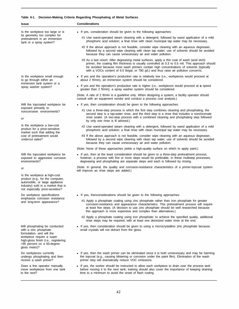
Table 6-1. Decision-Making Criteria Regarding Phosphating of Metal Surfaces
Issue Considerations
Is the workpiece too large or isits geometry too complex forpretreatment in an immersiontank or a spray system?
Is the workpiece small enoughto go through either animmersion tank system or aspray washer system?
Will the topcoated workpiece beexposed primarily tononcorrosive environments?
or
Is the workpiece a low-costproduct for a price-sensitivemarket such that adding thecost of pretreatment wouldundercut sales?
Will the topcoated workpiece beexposed to aggressive corrosiveenvironments?
or
Is the workpiece a high-costproduct (e.g., for the computer,automobile, or large applianceindustry) sold in a market that isnot especially price-sensitive?
Do workpiece specificationsemphasize corrosion resistanceand long-term appearance?
Will phosphating be conductedwith a zinc phosphateformulation, and will theworkpiece require a superhigh-gloss finish (i.e., registering>95 percent on a 60-degreegloss meter)?
Do workpieces currentlyundergo phosphating and thenreceive a wash primer?
Does a line operator manuallymove workpieces from one tankto the next?
l If yes, consideration should be given to the following approaches:
#1 Use wand-operated steam cleaning with a detergent, followed by wand application of a mildphosphoric acid solution; a final rinse with clean municipal tap water may be necessary.
#2 If the above approach is not feasible, consider wipe cleaning with an aqueous degreaser,followed by a second wipe cleaning with clean tap water; use of solvents should be avoidedbecause they can cause unnecessary air and water pollution.
#3 As a last resort: After degreasing metal surfaces, apply a thin coat of wash (acid etch)primer; the coating film thickness is usually controlled at 0.3 to 0.5 mil. This approach shouldbe avoided because most wash primers contain high concentrations of solvents (typicallywith a VOCs content of 6.5 lb/gal, or 780 g/L) and thus raise air pollution concerns.
l If yes and the operation’s production rate is relatively low (i.e., workpieces would proceed atabout 2 ft/min), an immersion system should be considered.
l If yes and the operation’s production rate is higher (i.e., workpieces would proceed at a speedgreater than 2 ft/min), a spray washer system should be considered.
(Note: A rate of 2 ft/min is a guideline only. When designing a system, a facility operator shouldconsult with an equipment vendor and conduct a process cost analysis.)
l If yes, then consideration should be given to the following approaches:
#1 Use a three-step process in which the first step combines cleaning and phosphating, thesecond step is a tap-water rinse, and the third step is a rinse that includes a nonchromaterinse sealer. (A two-step process with a combined cleaning and phosphating step followedby only one rinse is ill advised.)
#2 Use wand-operated steam cleaning with a detergent, followed by wand application of a mildphosphoric acid solution; a final rinse with clean municipal tap water may be necessary.
#3 If the above approach is not feasible, consider wipe cleaning with an aqueous degreaser,followed by a second wipe cleaning with clean tap water; use of solvents should be avoidedbecause they can cause unnecessary air and water pollution.
(Note: None of these approaches yields a high-quality surface on which to apply paint.)
l If yes, then at the least consideration should be given to a three-step pretreatment process;however, a process with five or more steps would be preferable. In these multistep processes,degreasing and phosphating are separate steps and each is followed by rinsing.
(Note: In general, the quality and corrosion-resistance characteristics of a primer-topcoat systemwill improve as rinse steps are added.)
l If yes, thenconsiderations should be given to the following approaches:
#1 Apply a phosphate coating using zinc phosphate rather than iron phosphate for greatercorrosion-resistance and appearance characteristics. This pretreatment process will requireat least five steps. (A decision to use zinc phosphate should be well researched becausethis approach is more expensive and complex than alternatives.)
#2 Apply a phosphate coating using iron phosphate; to achieve the specified quality, additionalrinse steps may be required, with at least one deionized water rinse at the end.
l If yes, then consideration should be given to using a microcrystalline zinc phosphate becausesmall crystals will not detract from the gloss.
l If yes, then the wash primer can be eliminated since it is both unnecessary and may be harmingthe topcoat (e.g., causing blistering or corrosion under the paint film). Elimination of the washprimer step will dramatically reduce VOC emissions.
l If yes, the worker should be instructed to allow each workpiece to drain over the process tankbefore moving it to the next tank; training should also cover the importance of keeping drainingtime to a minimum to avoid the onset of flash rusting.
42

Table 6-1. Decision-Making Criteria Regarding Phosphating of Metal Surfaces (continued)
Issue Considerations
Are workpieces automatically .moved from one tank to thenext via a computerized hoistcrane? .
Do workpieces pass through a .conveyorized spray washer?
.
Does the spray booth operator .have access to the conveyorsystem on/off switch? And doesthe operator on occasion stopthe system while workpiecesare still wet?
What approach isrecommended for selecting aphosphate formulation from themany that are available?
If yes, the system should be programmed to allow workpieces to drain over immersion tanks,while avoiding the onset of flash rusting.
If workpieces span a wide range of geometries, consideration should be given to programmingthe system for various groupings of workpieces.
If workpieces span a wide range of geometries, consideration should be given to programmingthe system for various groupings of workpieces.
The facility operator should conduct tests to determine the optimum conveyor system speed forallowing adequate workpiece draining (as opposed to changing the speed for different workpiececonfigurations).
If yes, then consideration should be given to the following approaches:
#1 The operator should be instructed not to stop the conveyor system until all workpieces havepassed through the spray washer and the dry-off oven; it is likely that allowing a workpieceto remain above a tank or between stages will ultimately cause a paint coating failure.
#2 Establish two separate conveyor systems: one that makes a loop around the spray washerand another that passes through the spray booths and the dry-off oven. The disadvantage ofthis approach is that the line operator must offload workpieces from the first conveyor andthen load them onto the second system.
#3 Install a power-and-free conveyor so that the speed of the conveyor as it passes through thespray washer can be faster than the speed of the second conveyor that passes through thepaint booths and dry-off oven. This approach is more expensive than the others, but it allowsworkpieces to accumulate after leaving the spray washer and avoids the need for a lineworker to offload and load workpieces, as required in approach #2.
The best approach is for the operator to test different formulations in the existing process line.Since this is usually not feasible, an alternative is to have several vendors phosphate testpieces, immediately after which a primer should be applied. Once the primer has cured, thecoating should be tested for adhesion and then for corrosion-resistance characteristics in a saltspray (i.e., fog) chamber. These tests will identify the best formulation.
Only by testing a formulation in the actual process line can the operator determine the typicaluseful life of a phosphating immersion bath.
(Note: Generally it is not possible to make an assessment regarding the most appropriatephosphate formulation by reviewing vendor data sheets.)
l In general, low-temperature formulations do not provide the same quality phosphate coating ashigh-temperature formulations. Thus, the tradeoff is between quality and energy costs.
Is it better to use a low- or ahigh-temperature phosphateformulation?
What approach is l A decision usually can be made on the basis of cost. Although powder formulations are generallyrecommended for selecting less expensive, the operator must mix the phosphating solution according to vendor literature. Inbetween powder and liquid contrast, liquid formulations come ready for use, although some dilution with water may bephosphate formulations? required.
Fe+ Phosphate Fe+
electrochemical process that leads to galvanic corrosionof the metal substrate.
This pretreatment step is specific to metal substrates.The phosphate coating process is not used on plasticsor ceramics because neither can participate in an elec-trochemical -reaction as can metals. The deposition ofphosphates only takes place if an electric current canflow through the substrate/liquid system (see Chapter 3for a discussion of the electrochemical reaction thattakes place in the corrosion process).
Figure 6-1. Cross-sectional view of conversion coating proc-ess using iron or zinc phosphate.
The discussion in this chapter primarily focuses onmethods for applying a phosphate coating to steel,which typically is accomplished by bath immersion orspraying of the workpiece with an iron or zinc phosphatesolution. These same phosphating methods also can beused on several other metals. For some substrates,
43
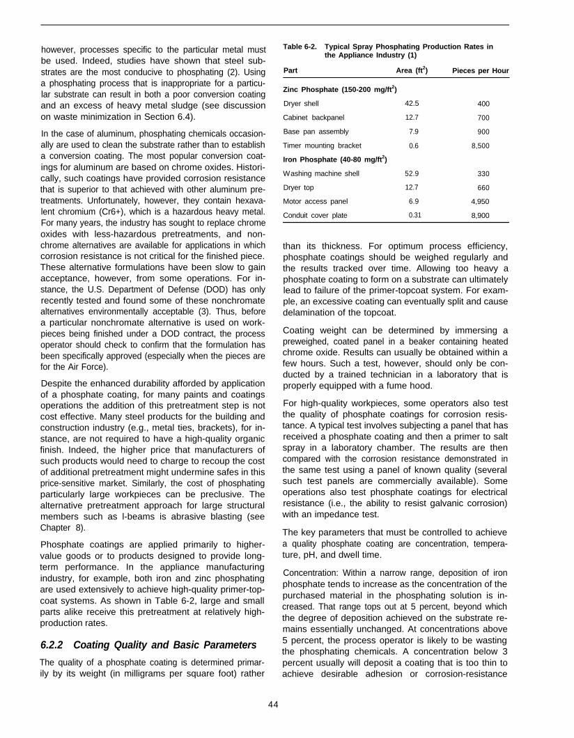
however, processes specific to the particular metal mustbe used. Indeed, studies have shown that steel sub-strates are the most conducive to phosphating (2). Usinga phosphating process that is inappropriate for a particu-lar substrate can result in both a poor conversion coatingand an excess of heavy metal sludge (see discussionon waste minimization in Section 6.4).
In the case of aluminum, phosphating chemicals occasion-ally are used to clean the substrate rather than to establisha conversion coating. The most popular conversion coat-ings for aluminum are based on chrome oxides. Histori-cally, such coatings have provided corrosion resistancethat is superior to that achieved with other aluminum pre-treatments. Unfortunately, however, they contain hexava-lent chromium (Cr6+), which is a hazardous heavy metal.For many years, the industry has sought to replace chromeoxides with less-hazardous pretreatments, and non-chrome alternatives are available for applications in whichcorrosion resistance is not critical for the finished piece.These alternative formulations have been slow to gainacceptance, however, from some operations. For in-stance, the U.S. Department of Defense (DOD) has onlyrecently tested and found some of these nonchromatealternatives environmentally acceptable (3). Thus, beforea particular nonchromate alternative is used on work-pieces being finished under a DOD contract, the processoperator should check to confirm that the formulation hasbeen specifically approved (especially when the pieces arefor the Air Force).
Despite the enhanced durability afforded by applicationof a phosphate coating, for many paints and coatingsoperations the addition of this pretreatment step is notcost effective. Many steel products for the building andconstruction industry (e.g., metal ties, brackets), for in-stance, are not required to have a high-quality organicfinish. Indeed, the higher price that manufacturers ofsuch products would need to charge to recoup the costof additional pretreatment might undermine safes in thisprice-sensitive market. Similarly, the cost of phosphatingparticularly large workpieces can be preclusive. Thealternative pretreatment approach for large structuralmembers such as l-beams is abrasive blasting (seeChapter 8).
Phosphate coatings are applied primarily to higher-value goods or to products designed to provide long-term performance. In the appliance manufacturingindustry, for example, both iron and zinc phosphatingare used extensively to achieve high-quality primer-top-coat systems. As shown in Table 6-2, large and smallparts alike receive this pretreatment at relatively high-production rates.
6.2.2 Coating Quality and Basic Parameters
The quality of a phosphate coating is determined primar-ily by its weight (in milligrams per square foot) rather
44
Table 6-2. Typical Spray Phosphating Production Rates inthe Appliance Industry (1)
Part Area (ft2)
Zinc Phosphate (150-200 mg/ft2)
Dryer shell 42.5
Cabinet backpanel 12.7
Base pan assembly 7.9
Timer mounting bracket 0.6
Iron Phosphate (40-80 mg/ft2)
Washing machine shell 52.9
Dryer top 12.7
Motor access panel 6.9
Conduit cover plate 0.31
Pieces per Hour
400
700
900
8,500
330
660
4,950
8,900
than its thickness. For optimum process efficiency,phosphate coatings should be weighed regularly andthe results tracked over time. Allowing too heavy aphosphate coating to form on a substrate can ultimatelylead to failure of the primer-topcoat system. For exam-ple, an excessive coating can eventually split and causedelamination of the topcoat.
Coating weight can be determined by immersing apreweighed, coated panel in a beaker containing heatedchrome oxide. Results can usually be obtained within afew hours. Such a test, however, should only be con-ducted by a trained technician in a laboratory that isproperly equipped with a fume hood.
For high-quality workpieces, some operators also testthe quality of phosphate coatings for corrosion resis-tance. A typical test involves subjecting a panel that hasreceived a phosphate coating and then a primer to saltspray in a laboratory chamber. The results are thencompared with the corrosion resistance demonstrated inthe same test using a panel of known quality (severalsuch test panels are commercially available). Someoperations also test phosphate coatings for electricalresistance (i.e., the ability to resist galvanic corrosion)with an impedance test.
The key parameters that must be controlled to achievea quality phosphate coating are concentration, tempera-ture, pH, and dwell time.
Concentration: Within a narrow range, deposition of ironphosphate tends to increase as the concentration of thepurchased material in the phosphating solution is in-creased. That range tops out at 5 percent, beyond whichthe degree of deposition achieved on the substrate re-mains essentially unchanged. At concentrations above5 percent, the process operator is likely to be wastingthe phosphating chemicals. A concentration below 3percent usually will deposit a coating that is too thin toachieve desirable adhesion or corrosion-resistance
characteristics. Thus, process operators generally mixphosphating solutions with a 3 to 5 percent concentrationof the purchased material. Similarly, specific parametersapply for zinc phosphate. Thus, process operators arestrongly advised to follow vendors’ recommendations.
Temperature: As with concentration; within a givenrange deposition increases as the temperature of thephosphating solution is raised. Process operators typi-cally maintain iron phosphate solutions at 120o to 140oF,in keeping with vendor recommendations. An exceptionapplies when using low-temperature phosphate materi-als, for which the phosphating solution is maintained at90°F. At temperatures above or below the vendor’s rec-ommendation, the phosphating reaction might be toofast or too slow, respectively. For instance, if phos-phating occurs too quickly, the deposition may be ex-tremely porous. Moreover, phosphating at a hightemperature raises energy costs and increases theevaporation of water from the phosphating solution.Similarly, specific parameters apply for zinc phosphate.
Phosphate baths and spray feeds are generally heatedby either a burner-and-tube system or by a heat ex-changer that incorporates steam. Although the burner-and-tube method has been in use for many years, themore recently installed phosphating equipment tends toincorporate heat exchanger technology, which is moreenergy efficient and does not generate fumes.
pH: The pH of an iron phosphate bath gives an indica-tion of the acidity. Typical iron phosphating solutions areslightly acidic, in a pH range of 3 to 6 for both immersionand spray applications; zinc phosphating solutions gen-erally are more acidic, in a pH range of 1.8 to 2.4 forimmersion and up to 3.0 for spray application (4). Con-trol of pH is critical because the phosphate precipitatesout from the solution only when the pH at the sub-strate/liquid interface is in the correct range. Becausethe pH range is specific to the particular phosphateformulation, vendor recommendations must be followedexactly.
Dwell Time: For both iron and zinc phosphating, the dwelltime required to achieve an adequate conversion coat-ing differs significantly between immersion and sprayapplication. Depending on the concentration of the pur-chased material, a workpiece immersed in an agitatedbath of phosphating solution generally requires a dwelltime of 3 to 5 minutes. Agitation brings the fresh chemi-cal in the bath to the substrate/liquid interface, where theelectrochemical reactions occur. Thus, agitation is rec-ommended to achieve uniform deposition and to maxi-mize chemical use. In sharp contrast, with sprayapplication the phosphating solution only has to makecontact with the workpiece for 60 to 90 seconds. Theconversion reaction occurs faster because the spraysolution continuously supplies fresh chemicals to thesurface of the workpiece.
6.2.3 Best Management Practices
Recommended practices that enhance process effi-ciency as well as the quality of the phosphate coatinginclude the following:
To promote proper adhesion for high-durabilityprimer-topcoat systems and to extend the life of im-mersion baths, process operators should ensure thatworkpieces are thoroughly rinsed before and afterphosphating.
To maximize the effectiveness of phosphating formu-lations, operators should confer regularly with ven-dors and thoroughly test various combinations ofacids, accelerators, and surfactants. For many opera-tions, it may be necessary to customize the phos-phating formulation to the specifications of theparticular coating system.
To ensure the cost-effective use of chemicals, facilityoperators should automate the addition of the phos-phating formulation to processing tanks. Althoughcapital cost outlays for the installation of flow control-lers can be somewhat high, this measure can yieldprocess input savings in the near term.
To avoid contaminating the phosphated surface withperspiration, skin oils, or general grime, facility op-erators should require process line workers to wearclean gloves when handling freshly phosphated work-pieces. Such contaminants can undermine adhesionof the primer-topcoat system and mar the finish byphotographing through.
6.3 Phosphating Methods
6.3.1 Iron Phosphating
For most operations that apply a conversion coating tosteel workpieces, iron phosphating is the preferred ap-proach because it is easier to control, less expensive,and generates less sludge than the zinc phosphatemethod. Iron phosphate yields a conversion coating thatgenerally has less weight than that achieved with zincphosphating, however, and thus the coating providesless corrosion resistance. Nonetheless, the quality ofthe deposition is sufficient to meet specifications for themajority of finished workpieces. Although iron phos-phate can be used on most steel substrates, it is incom-patible with galvanized steel, for which zinc phosphateis recommended.
The iron phosphate process is essentially the pickling ofsteel in phosphoric acid. The surface of the steel ismade up of numerous anode and cathode sites. Theacid attacks the steel at the anodes, liberating iron ionsinto the bath and generating hydrogen gas. An accelera-tor (i.e., oxidizing agent) is required to oxidize the ironions and use up the hydrogen at the metal surface. This
45
lowers the acid content, or pH, at the cathodic sites tothe point at which iron phosphate naturally precipitatesonto the steel surface. This process continues until allcathodic sites (i.e., all surfaces) are coated.
Iron phosphate formulations generally contain a combi-nation of ferrous phosphate, ferric phosphate, and ferricoxide. Process operators typically use solutions thatinclude phosphoric acid, an accelerator, and one ormore surfactants (ironically, iron phosphate solutions donot actually contain iron). The surfactants help to wet thesubstrate, enhancing adhesion of the phosphate coating.
The four types of available iron phosphates are catego-rized by the accelerator added:
Chlorate (yielding a gold-blue-gray deposition).
Molybdate (yielding a blue deposition).
Sodium metanitrobenzene sulfonate (SNIBS) (yield-ing a grayish blue deposition).
Bromate (yielding a blue to bluish gray deposition).
The color of the phosphate coating should be consistentfrom workpiece to workpiece. A change in color canindicate a problem with the deposition (e.g., the immer-sion bath is exhausted).
The four types of iron phosphates are sold in both liquidand powder form. The liquid form is generally preferredbecause it is easier to mix into an immersion bath orspray tank. Powders can be difficult to mix thoroughlyinto an aqueous form and can generate housekeepingproblems. Also, the mix-and-feed of powdered formula-tions cannot be automated as easily as liquid forms.
Typical deposition weights achieved with iron phos-phating range from 25 to 80 mg/ft.1 Deposition weightdepends not only on the control of phosphating processparameters, but also on the type of steel or alloy beingtreated. Some steels are particularly difficult to-treat. Onsuch substrates, deposition weights may be low regard-less of how well the phosphating system is controlled.
6.3.1.1 Process Variations
Wand Application
One method for applying an iron phosphate coating isto subject the workpiece to the phosphating solution witha spray wand. Often the workpiece can be degreasedbefore phosphating and then rinsed afterward using asingle wand equipped with an operator feed-source con-trol (see discussion in Chapter 5 on aqueous degreas-ing). Wand application is primarily used on particularly
1 As noted in Chapter 5, “degreasing” is used generally in this docu-ment to refer to the various liquid/vapor methods used in paints andcoatings operations to clean substrates. The author recognizes thatsome operators use the term degreasing to refer specifically tovapor degreasing.
large workpieces being processed at low volume. Ingeneral, this approach does not yield a high-qualitysurface for application of a primer-topcoat system.
Two-Step Process With Immersion
Another approach involves immersing workpieces into abath that contains a formulation that combines degreas-ing and phosphating. The workpiece is then rinsed in thesecond step in this process. Although economical, thisapproach tends to leave many contaminants on thesubstrate, and thus the resulting phosphate coating pro-vides only minimal corrosion resistance. Generally, thisapproach is used to phosphate workpieces that will notbe exposed to corrosive conditions during most of theiruseful life.
Three-Step Process With Immersion or Spray Washing
The most widely used iron phosphating approach in thegeneral metals industry involves an immersion bath orspray washing step that combines degreasing and ironphosphating followed by two rinse steps. Rinsing can becarried out with municipal tap water, although deionizedwater is recommended for the second rinse as a way ofcontrolling for residual contaminants. Some operationsalso add a sealer to the second rise that fills pores in thephosphate coating (see discussion on sealers in Chap-ter 7). Whereas the three-step process minimizes phos-phating costs, the corrosion resistance yielded is not ofsufficient quality to meet specifications for higher-valueworkpieces (e.g., appliances and many other durablegoods). (Operations generally do not use a four-stepprocess.)
Processes With Five or More Steps
Operations applying paints and coatings that requirehigh-grade corrosion resistance thoroughly clean andrinse workpieces before and after phosphating. In thesesystems, phosphating as well as degreasing and rinsingare carried out in dedicated immersion baths or withspray washers.
The five-step approach (i.e., degreaser, tap-water rinse,phosphating, tap-water rinse, and deionized watersealer rinse) often is used for phosphating workpiecesthat will be put into service outdoors or in generallycorrosive environments. Operations coating workpieceswith specifications for superior durability (e.g., for largeappliances) often use seven or more process steps thatinclude additional rinsing, either by impingement or im-mersion. Tables 6-3 and 6-4 present examples of twomultiple-step process lines for high-quality workpieces.Iron phosphating using such extensive processes yieldsconversion coatings of quality similar to that achievedwith zinc phosphate. Limitations of such approachesconcern process costs related to worker training, opera-tion of the system, and floor-space needs.
46

Table 6-3. Process Line for Pretreatment of ComplexWorkpieces in Electrocoating Operation (5)
Stage Description Process Time
1 Alkaline cleaner Spray 60 sec
2 Alkaline cleaner Immersion 30 sec
3 Water rinse Spray 30 sec
4 Water rinse Immersion 30 sec
5 Phosphate Immersion 60 sec
6 Water rinse Immersion 30 sec
7 Sealer Immersion 30 sec
8 Deionized rinse Immersion 30 sec
8a Deionized make-up Spray Variable
Drain and flash 5 min
Table 6-4. Process Line for Pretreatment of SimpleWorkpieces in Electrocoating Operation (5)
Stage Description Process Time
1 Alkaline cleaner Spray 60 sec
2 Alkaline cleaner Spray 30 sec
3 Water rinse Spray 30 sec
4 Water rinse Spray 30 sec
5 Phosphate Spray 60 sec
6 Water rinse Spray 30 sec
7 Sealer Spray 30 sec
8 Deionized rinse Spray 30 sec
8a Deionized make-up Spray Variable
Drain and flash 5 min
6.3.2 Zinc Phosphating
In most operations where the corrosion resistance offinished workpieces must be especially high, conversioncoatings are applied using zinc phosphate. This ap-proach is widely used in the automotive industry and incertain sectors of the appliance and electronics indus-tries. Similarly, zinc phosphating is often specified by thearmed services, especially for equipment that may beexposed to severe environments. Moreover, many op-erations using electrocoating or powder coatings, par-ticularly when a one-coat finish will be exposed to theweather, pretreat workpieces with zinc phosphate.
The electrochemical process whereby zinc phosphatedeposits on a substrate is similar to the iron phosphatingprocess. As soon as the workpiece is subjected to theacidic solution, metal dissolves at anodic sites.
As in iron phosphating, accelerators (i.e., oxidizers) arean important addition to zinc phosphating solutions. Inzinc formulations, accelerators oxidize the iron ions anduse up the hydrogen at the metal surface. This lowers
47
the acid content, or pH, at the cathodic sites to the pointat which zinc phosphate naturally precipitates onto thesteel surface. This process continues until all cathodicsites are coated.
The accelerator performs two basic functions:
l The excess ferrous ions in the solution tend to slowdown the phosphating process. The acceleratorspeeds up the process by oxidizing the excess ironions, causing them to precipitate out as a ferric phos-phate sludge, which extends the life of the bath. (Thesludge must later be filtered out of the solution anddisposed of as a hazardous waste.)
l By reacting with hydrogen as it is formed at the an-odic sites, the accelerator prevents hydrogen gas for-mation. If an oxidizer were not used, the formation ofgas would interfere with the deposition of the phos-phate. Thus, addition of an oxidizer (also known asa depolarizer) frequently prevents hydrogen embrit-tlement of high-strength steel.
Accelerators specifically used with zinc phosphaterange in reactivity from mild nitrates to the fairly aggres-sive chlorates and peroxides. Calcium compounds areparticularly favored as accelerators for the low coatingweights and compact grain sizes they yield. These typi-cally are used when higher temperature phosphatingsolutions (i.e., 112o to 130°F) would otherwise slowconversion kinetics (6). They can also be used in lowertemperature baths when accelerators or initiators suchas nickel, iron, manganese, and borium are also used.
In general, the crystals that result from zinc phosphatinghave low porosity and provide a strong base for adhe-sion of the primer-topcoat system and superior long-term corrosion resistance. Table 6-5 presents thecorrosion resistance of various zinc phosphate coatingswhen subjected to salt spray.
The performance of zinc phosphate formulations in-creases in the following order:
l Zinc phosphate
l Zinc-calcium phosphate
l Zinc-nickel-fluoride phosphate
l Zinc-nickel-magnesium-fluoride phosphate
Typical conversion coatings deposited on the substratein zinc phosphating include:
Phosphopyllite Zn2Fe(P04)2.4H20Hopeite Zn3(P04)2.4H20
Scholzite Ca2Zn(P04)2.2H20Brushite CaHP04.2H20Monetite CaHP04
Crystal size also is affected by the method used forsubjecting the workpiece to the phosphating solution

Table 6-5. Corrosion Resistance of Zinc Phosphate Coatingson Steel and Electrogalvanized Steel (1)
Coating
Steel
ConstantTemperature Water
Salt Spray Condensate(DIN 50021 SS) (DIN 50017)
Untreated
Zinc phosphate(unaccelerated)a
0.1 0.1
6 40
Zinc phosphate(nitrate accelerated)a
3 24
Zinc phosphate(nitrate accelerated withnickel and polycarbonicacid additions)a
250 800
Zinc phosphate(nitrate accelerated +corrosion protection oil)a
250 700
Electrogalvanized Steel
Untreated
Zinc phosphate(nitrate + nitriteaccelerated)b
1 24
50 150
a Approximate coating weight was 25 g/m2 (2,322 mg/ft2).b Approximate coating weight was 2 g/m2 (186 mg/ft2).Note: These coatings were intended to provide corrosion protectionwithout the benefit of an organic paint or coating.
and by the thoroughness of the rinsing steps. The par-ticular phosphating method used, however, often de-pends on the type of workpiece. Typical zinc phosphatecoating weights are 100 to 1,000 mg/ft2 using sprayapplication, whereas coatings can range from 150 to4,000 mg/ft2 using immersion tanks (4).
Fewer process variations are applicable to zinc phos-phating, given that process operators must thoroughlyrinse drag-out and contaminants from workpieces be-fore and after phosphating. Also, each spray or immer-sion step must be specific to the particular processstage. Thus, for instance, the degreasing and phos-phating steps cannot be combined, as they are some-times in the iron phosphating approach. For operationsusing zinc phosphating, the process line includes five ormore steps in which workpieces are degreased, tap-water rinsed, phosphated, tap-water rinsed, and thenrinsed with deionized water.
6.3.3 Wash Primers as an Alternative toPhosphating
Wash primers represent an alternative means of etchinga substrate in preparation for receiving a topcoat. Thesecoatings are used primarily on particularly large work-pieces that cannot be treated in tanks. The conventionalapproach for this low-cost pretreatment step, whichdates back to the 1940s involves priming the workpiece
with a high-VOC coating formulation that slightly etchesthe substrate; this approach is also known as acid etch.A typical wash primer is a vinyl butyryl organic coatingformulated with solvents (e.g., ethyl alcohol and/or iso-propyl alcohol), vinyl butyryl resin, phosphoric acid, zincchromate, water, and an extender pigment.
The high VOC content of conventional wash primers incontrast to other primer coatings represents a significantdisadvantage of this approach. The VOC content intypical formulations is about 6.5 lb/gal (780 g/L). Thus,the use of wash primers is an inexpensive but low-qual-ity alternative to phosphating. Typically, facility operatorsresort to this approach only when a phosphating processline is not an option.
Because most states now require that the VOC contentof wash primers not exceed 3.5 lb/gal, facility operatorsthat favor this approach have been experimenting withthe less-volatile water-borne wash primers that havebecome available in recent years. Some of these alter-native formulations may meet the military’s stringentspecifications for quality and pollution prevention (7).
6.4 Waste Minimization and Treatment
6.4.1 Minimization
The key to waste minimization in the phosphating stageof a paints and coatings operation is process efficiency.Applying conversion coatings to workpieces with phos-phating chemicals that are appropriate for the particularmetal substrate can minimize the generation of heavymetal sludge in immersion baths or from phosphatingspray operations. If the color of a deposited coatingvaries from the coloration associated with particularphosphating formulations, the process operator shouldcheck for problems such as exhaustion of the phos-phating solution. Both the monitoring of phosphatingoperations and the replenishing of chemicals can beautomated to ensure maximum process efficiency.
In general, some amount of heavy metal sludge is gen-erated in all phosphating, with greater amounts associ-ated with zinc phosphating. In the worst case, the useof phosphating chemicals that are not well suited to aworkpiece’s metal substrate will fail to deposit a coatingand will generate an excess of heavy metal sludge. Forexample, iron phosphate cannot be used to apply aconversion coating to galvanized steel because the acidwill react with the zinc in the substrate but not the iron,resulting in an excess of zinc sludge. Instead, a zincphosphate formulation should be used to apply a con-version coating on galvanized steel. Similarly, an alumi-num substrate will not receive a conversion coating fromiron phosphate and will generate an excess of aluminumsludge. Aluminum phosphate should be used to applyconversion coatings to aluminum workpieces. Some
48
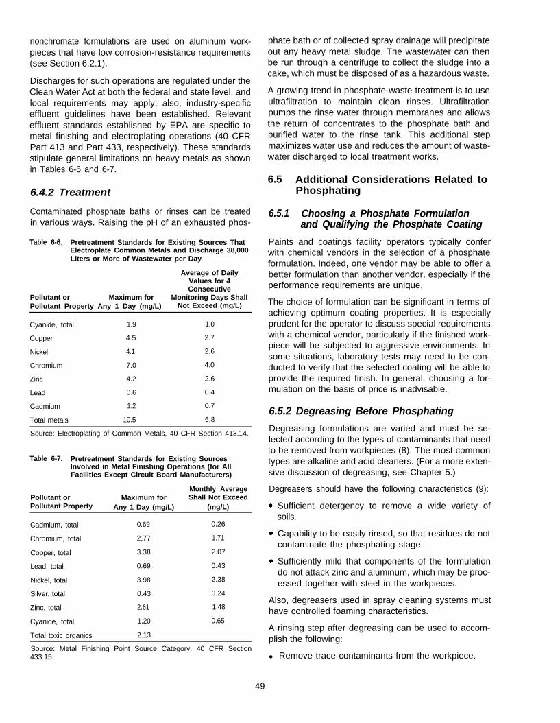
nonchromate formulations are used on aluminum work-pieces that have low corrosion-resistance requirements(see Section 6.2.1).
Discharges for such operations are regulated under theClean Water Act at both the federal and state level, andlocal requirements may apply; also, industry-specificeffluent guidelines have been established. Relevanteffluent standards established by EPA are specific tometal finishing and electroplating operations (40 CFRPart 413 and Part 433, respectively). These standardsstipulate general limitations on heavy metals as shownin Tables 6-6 and 6-7.
6.4.2 Treatment
Contaminated phosphate baths or rinses can be treatedin various ways. Raising the pH of an exhausted phos-
Table 6-6. Pretreatment Standards for Existing Sources ThatElectroplate Common Metals and Discharge 38,000Liters or More of Wastewater per Day
Average of DailyValues for 4Consecutive
Pollutant or Maximum for Monitoring Days ShallPollutant Property Any 1 Day (mg/L) Not Exceed (mg/L)
Cyanide, total 1.9 1.0
Copper 4.5 2.7
Nickel 4.1 2.6
Chromium 7.0 4.0
Zinc 4.2 2.6
Lead 0.6 0.4
Cadmium 1.2 0.7
Total metals 10.5 6.8
Source: Electroplating of Common Metals, 40 CFR Section 413.14.
Table 6-7. Pretreatment Standards for Existing SourcesInvolved in Metal Finishing Operations (for AllFacilities Except Circuit Board Manufacturers)
Monthly AveragePollutant or Maximum for Shall Not ExceedPollutant Property Any 1 Day (mg/L) (mg/L)
Cadmium, total 0.69 0.26
Chromium, total 2.77 1.71
Copper, total 3.38 2.07
Lead, total 0.69 0.43
Nickel, total 3.98 2.38
Silver, total 0.43 0.24
Zinc, total 2.61 1.48
Cyanide, total 1.20 0.65
Total toxic organics 2.13
Source: Metal Finishing Point Source Category, 40 CFR Section433.15.
phate bath or of collected spray drainage will precipitateout any heavy metal sludge. The wastewater can thenbe run through a centrifuge to collect the sludge into acake, which must be disposed of as a hazardous waste.
A growing trend in phosphate waste treatment is to useultrafiltration to maintain clean rinses. Ultrafiltrationpumps the rinse water through membranes and allowsthe return of concentrates to the phosphate bath andpurified water to the rinse tank. This additional stepmaximizes water use and reduces the amount of waste-water discharged to local treatment works.
6.5 Additional Considerations Related toPhosphating
6.5.1 Choosing a Phosphate Formulationand Qualifying the Phosphate Coating
Paints and coatings facility operators typically conferwith chemical vendors in the selection of a phosphateformulation. Indeed, one vendor may be able to offer abetter formulation than another vendor, especially if theperformance requirements are unique.
The choice of formulation can be significant in terms ofachieving optimum coating properties. It is especiallyprudent for the operator to discuss special requirementswith a chemical vendor, particularly if the finished work-piece will be subjected to aggressive environments. Insome situations, laboratory tests may need to be con-ducted to verify that the selected coating will be able toprovide the required finish. In general, choosing a for-mulation on the basis of price is inadvisable.
6.5.2 Degreasing Before Phosphating
Degreasing formulations are varied and must be se-lected according to the types of contaminants that needto be removed from workpieces (8). The most commontypes are alkaline and acid cleaners. (For a more exten-sive discussion of degreasing, see Chapter 5.)
Degreasers should have the following characteristics (9):
Sufficient detergency to remove a wide variety ofsoils.
Capability to be easily rinsed, so that residues do notcontaminate the phosphating stage.
Sufficiently mild that components of the formulationdo not attack zinc and aluminum, which may be proc-essed together with steel in the workpieces.
Also, degreasers used in spray cleaning systems musthave controlled foaming characteristics.
A rinsing step after degreasing can be used to accom-plish the following:
l Remove trace contaminants from the workpiece.
49
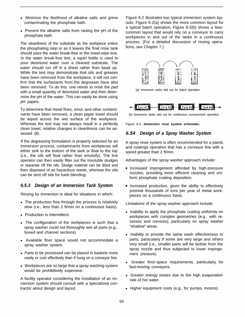
l Minimize the likelihood of alkaline salts and grimecontaminating the phosphate bath.
l Prevent the alkaline salts from raising the pH of thephosphate bath.
The cleanliness of the substrate as the workpiece entersthe phosphating step or as it leaves the final rinse tankshould pass the water break-free or the towel-wipe test.In the water break-free test, a squirt bottle is used topour deionized water over a cleaned substrate. Thewater should run off in a sheet rather than bead up.While the test may demonstrate that oils and greaseshave been removed from the workpiece, it will not con-firm that the surfactants from the degreaser have alsobeen removed. To do this, one needs to rinse the partwith a small quantity of deionized water and then deter-mine the pH of the water. This can easily be done usingpH papers.
To determine that metal fines, smut, and other contami-nants have been removed, a clean paper towel shouldbe wiped across the wet surface of the workpiece.Whereas the test may not always result in a perfectlyclean towel, relative changes in cleanliness can be as-sessed (8).
If the degreasing formulation is properly selected for animmersion process, contaminants from workpieces willeither sink to the bottom of the tank or float to the top(i.e., the oils will float rather than emulsify). The lineoperator can then easily filter out the insoluble sludgesor separate off the oils. Sludge material can be dried andthen disposed of as hazardous waste, whereas the oilscan be sent off site for fuels blending.
6.5.3 Design of an Immersion Tank System
Rinsing by immersion is ideal for situations in which:
l The production flow through the process is relativelyslow (i.e., less than 2 ft/min on a continuous basis).
l Production is intermittent.
l The configuration of the workpieces is such that aspray washer could not thoroughly wet all parts (e.g.,boxed and channel sections).
l Available floor space would not accommodate aspray washer system.
l Parts to be processed can be placed in baskets moreeasily or cost effectively than if hung on a conveyor line.
l Workpieces are so large that a spray washing systemwould be prohibitively expensive.
A facility operator considering the installation of an im-mersion system should consult with a specialized con-tractor about design and layout.
Figure 6-2 illustrates two typical immersion system lay-outs: Figure 6-2(a) shows the more common layout fora typical batch operation; Figure 6-2(b) shows a less-common layout that would rely on a conveyor to carryworkpieces in and out of the tanks in a continuousprocess. (For a detailed discussion of rinsing opera-tions, see Chapter 7.)
(a) Immersion tanks laid out for batch operation.
(b) Immersion tanks laid out for continuous conveyorized operation.
Figure 6-2. Immersion rinse system schematic.
6.54 Design of a Spray Washer System
A spray rinse system is often recommended for a paintsand coatings operation that has a conveyor line with aspeed greater than 2 ft/min.
Advantages of the spray washer approach include:
Increased impingement afforded by high-pressurenozzles, providing more efficient cleaning and uni-form phosphate coating deposition.
Increased production, given the ability to effectivelypretreat thousands of tons per year of metal work-pieces on a continuous basis.
Limitations of the spray washer approach include:
l Inability to apply the phosphate coating uniformly onworkpieces with complex geometries (e.g., with re-cesses and crevices), particularly on spray washer“shadow” areas.
l Inability to provide the same wash effectiveness toparts, particularly if some are very large and othersvery small (i.e., smaller parts will be farther from thespray nozzle and thus subjected to lower impinge-ment pressure).
l Greater floor-space requirements, particularly forfast-moving conveyors.
l Greater energy losses due to the high evaporationrate of hot water.
l Higher equipment costs (e.g., for pumps, motors).
50

l Higher maintenance costs due to the need for fre-quent cleaning and replacement of nozzles, as wellas the need to lubricate the conveyor system, whichis continuously subjected to a moist environment.
A facility operator considering the installation of a spraywasher line would be well advised to consult with aspecialized contracting company. In general, when plan-ning for a spray washer, the facility operator needs toconsider how the layout will affect process flow. Thespray washer system must be designed so that work-pieces can easily pass through the pretreatment proc-ess, allowing adequate time for the solutions to drainbetween each tank.
A spray washer system cannot be properly designedunless the conveyor line speed and the part sizes areknown. The dimensions of the spray tunnel must bebased on the silhouette of the maximum part size. Thespray nozzles inside the tunnel must be located onrisers so that they are only a few inches away from thelargest part.
When possible, a system should be designed so that sprayrinses precede every process tank. Although the rinses areat low pressures, they enhance pretreatment by prevent-ing the contamination of tanks with chemicals from apreceding tank. Operation of such spray washers is rela-tively inexpensive because low volumes of water are used.
Given the vast number of workpieces and parts of vary-ing size that can pass through a spray system each dayfor certain operations, nozzles can often be misdirected.Thus, a maintenance engineer should routinely check tosee that spray nozzles are pointing in the correct direction.
A design feature often overlooked regards conveyorsthat pass workpieces through the tunnel, dry-off oven,and spray booths, as shown in Figure 6-3. The advan-
tage of such designs is that line workers are only neededfor hanging and offloading workpieces.
6.5.5 Process and Quality Control Measures
Specification TT-490-D (7) is the military specificationthat covers cleaning and pretreating ferrous surfaces fororganic coatings. This document is useful even for op-erations not performing work for the military because itprovides excellent guidelines for process and qualitycontrol (see also Reference 10).
Beyond following general guidelines, it is imperative thatfacility operators conduct process control tests recom-mended by the vendor on a regular basis. These includetests relating to pH, concentration, total acid, tempera-ture, and dwell time. Also, operators should be carefulthat processing tanks do not become over contaminatedbecause the effectiveness of pretreatment can beundermined.
6.6 References
1.
2.
3.
4.
5.
6.
Rausch, W. 1990. The phosphating of metals. ASM Internationaland Finishing Publications. American Society of Metals Interna-tional, Metals Park, OH. p. 140.
Yaniv, A.E. 1979. The influence of surface preparation on thebehavior of organic coatings. Metal Finishing (Nov.), pp. 55-61.
Hurd, J. et al. Chromate conversion coating elimination from5,000-series armor-grade aluminum. Metal Finishing (in press).
American Society of Metals (ASM). 1982. Nonmetallic coatingprocesses. In: Metals Handbook (9th ed.), vol. 5, p, 434. ASMInternational, Metals Park, OH.
Kraft, K. 1994. Electrocoat system design. Symposium Proceed-ings for Electrocoat ‘94, Orlando, FL, March 23-25. Sponsoredby Products Finishing, Gardner Publications, Clough Pike, OH.
Nair, U.B. 1995. Calcium as a phosphating additive: An overview.Metal Finishing 93(3):40 (March).
51

7.
8.
9.
10.
General Services Administration. No date. Federal Specification Gruss, B. 1995. Iron phosphating. In: Metal Finishing Organic GuideTT-490-D. Cleaning methods and pretreatment of ferrous sur- Book and Directory, vol. 93 (No. 4A). New York, NY: Elsevierfaces for organic coatings. Science Publishers.
Gotoff, D.M. 1995. Troubleshooting pretreatment systems. In:The Finishing Line, vol. 10(1). Society of Manufacturing Engineers.
Witke, W.J. 1994. Product Finishing Directory. Clough Pike, OH:Gardner Publications. p. 74.
Rausch, W. 1990. The Phosphating of Metals. Teddington, England:Finishing Publications.
Woods, K. and S. Spring. 1979. Zinc phosphating. Metal Finishing77:24-60 (March).
Menke, J.T. 1994. Process control for phosphate coating. Prod-ucts Finishing 58:57-61 (January). Wood, W.G., ed. 1982. Surface cleaning, finishing and coating. In:
Metals Handbook (9th ed.), vol. 5. American Society for Metals.Metals Park, OH.
6.7 Additional Reading
Errikson, M. 1995. Zinc phosphating. In: Metal Finishing OrganicGuide Book and Directory, vol. 93 (No. 4A). New York, NY: El-sevier Science Publishers.
Gruss, B. 1995. Cleaning and surface preparation. In: Metal FinishingOrganic Guide Book and Directory, vol. 93 (No. 4A). New York,NY: Elsevier Science Publishers.
Acknowledgment
The author wishes to acknowledge Joe Schrantz, formereditor of Industrial Finishing Journal, for his contributionto the information in this chapter.
52
Chapter 7Rinsing Process Efficiency and Alternatives to Chromate-Based Sealers
7.1 Introduction
7.1.1 Pollution Prevention Considerations
Thorough rinsing is the most important factor in thepaints and coatings process for ensuring that work-pieces receive a high-quality finish. Without rinsingaway residual surfactants, excess alkalinity, or unre-acted acids, for example, a finish can degrade prema-turely, if not fail catastrophically. Sealing the phosphatecoating can be equally important for ensuring the qualityof the finished piece.
Pollution prevention is a critical consideration for theseprocess steps because many operations generate highvolumes of wastewater when rinsing and sealing work-pieces. Additionally, the chromate-based formulationstraditionally used in sealing rinse baths generate toxicresidues, some of which must be handled as hazardouswaste.
Often, however, these wastes can be minimized throughprocess modifications that can yield overall efficienciesand cost savings. The volumes of rinse wastewatergenerated, for instance, can be dramatically reduced atthe same time that rinsing efficiency is enhanced byusing a multiple-bath method called counter-flow rins-ing. Similarly, the generation of hazardous chromateresiduals can be controlled, and in some cases elimi-nated, by switching to nonchromate formulations. Whilenontoxic sealers are not considered as effective as chro-mate-based formulations in all operations, many proc-esses may realize cost and process benefits from usingthese alternatives.
These pollution prevention approaches are discussed inthis chapter in the context of best management practicesassociated with the rinsing and sealing process steps.In a general sense, any process operated efficientlycontrols the unnecessary generation of pollution to thedegree that the operation minimizes overall waste andthe number of workpieces that must be rejected anddisposed of or reprocessed. Indeed, the pretreatmentprocess stages of rinsing and sealing are particularlyimportant in a right-first-time approach to applying paintsand coatings. By ensuring thorough rinsing and sealing,
an operator can avoid corrective measures, which tendto be both chemically intensive and expensive.
7.1.2 Decision-Making Criteria
Decision-making criteria relevant to rinsing process effi-ciency and alternatives to chromate-based sealers, asaddressed in this chapter, are highlighted in Table 7-1.
7.2 Rinsing
The primary purpose of the rinsing step in the paints andcoatings process is to clean contaminants from theworkpiece before it moves on to the next stage in thesequence. Depending on where rinsing takes place inthe overall process, contaminants can include dirt, sand-ing dust, metal fines, or any other particulates as well aschemicals, solvents, or residues that may adhere to theworkpiece. Thorough rinsing can both enhance the ulti-mate quality and durability of the finished piece andminimize contamination of downstream steps in theprocess flow.
The number of rinsing steps in a process, as well as thenumber of baths in a given step, primarily depends onthe quality requirements for the finished workpiece. In-deed, rinsing might be left out entirely from the paintsand coatings process for a particularly low-value piece;however, best management practice would argue infavor of a minimum of one rinsing stage to maximizeprocess efficiency by controlling drag-out from one bathto another. The most effective method of rinsing is thecounter-flow approach, which relies on multiple baths toprovide thorough rinsing of the workpiece while minimiz-ing the volume of rinse water used (see Section 7.2.2).
The typical process flow for a high-value paints andcoatings operation includes a step for rinsing the clean-ing-formulation residues from the workpiece after de-greasing and then rinsing the piece again afterphosphating to remove unreacted acids. These two rins-ing steps are described below following a brief discus-sion of the basics of the rinsing process. This sectionalso includes a discussion of wastewater minimizationusing the counter-flow rinsing approach.
53

Table 7-1. Decision-Making Criteria Regarding Rinsing Processes
issue Considerations
Does the pretreatment systeminclude degreasing andphosphating as a single stage?
Does the pretreatment systeminclude degreasing andphosphating as separate stages?
Will the paint finish on workpiecesbe solely for appearance (i.e.,corrosion and other physicalproperties have little significance)?
Will the finished workpieces berequired to have only lowcorrosion resistance (i.e., be ableto withstand between 96 and 168hours of salt fog exposure perASTM B-117 [see Reference 1])?
Will the primed workpieces berequired to have moderatecorrosion resistance (i.e., be ableto withstand between 168 and 500hours of salt fog exposure perASTM B-117 [see Reference 1])?
Will the finished workpieces berequired to have superiorcorrosion resistance (i.e., be ableto withstand at least 500 hours ofsalt fog exposure)?
is the useful life of the phosphatebath shorter than what is projectedin vendor literature?
.
.
.
.
.
.
.
.
.
.
.
.
.
.
.
.
.
.
.
.
.
.
.
.
.
.
.
.
.
.
If yes, then rinsing before phosphating is not a consideration.
Regardless of whether these stages are separate, at least one rinse with municipal tap watershould follow phosphating.
Addition of a sealing rinse in a static tank should also be considered.
if yes, then rinsing with tap water after degreasing should be included.
Many low-value workpieces (i.e., household products) for price-sensitive markets are in thiscategory. Manufacturers often cannot justify improvements in the coatings process on avalue-added basis.
When corrosion-resistance requirements are low, it may be cost effective to conduct degreasingand phosphating in one step, followed by at least one municipal tap water rinse.
Addition of a sealing rinse in a static tank should also be considered.
Most finished metal products are in this category because they might be subjected to amoderate degree of outdoor exposure (i.e., not particularly corrosive elements).
It may be cost effective to conduct degreasing and phosphating in one step.
Consideration should be given to separate stages, with at least one tap water rinse between thetwo stages.
If separate stages are used, a second post-degreasing rinse with deionized water should beconsidered for extending the useful life of the phosphating bath. The second bath is particularlyimportant if the process line does not allow time for sufficient draining before phosphating.
A sealing rinse should be considered mandatory.
If it can be shown that the primer-topcoat system will provide the required corrosion resistance,consideration should be given to using a nonchromate sealer.
Rinse drainage should be collected and recycled.
If two or more rinse tanks follow degreasing or phosphating, consideration should be given tousing a counter-flow system.
If one or more of these rinses use deionized water, consideration should be given to installingautomatic flow controllers, which monitor the concentration of chemicals in the rinse tank.
If degreased and phosphated workpieces will be stored outdoors for several days prior toapplication of a primer-topcoat system, consideration should be given to using a chromatesealer for enhanced corrosion resistance. Expectations are that nonchromate sealers eventuallywill be proven fully equivalent to conventional sealers in corrosive environments.
This might apply to products that are subjected to outdoor exposure in all types of weather, tomarine environments, or to chemical vapors.
Same considerations as for low-corrosion resistance requirements above, although additionalemphasis should be placed on multiple rinse steps.
This usually applies to workpieces in automotive manufacturing. Electrocoating is used on mostautomotive parts, a process that cannot tolerate any drag-in from pretreatment steps.
Following degreasing, the workpiece must undergo at least one tap water rinse followed by adeionized water rinse.
At least two tap water post-phosphating rinses must be included, followed by rinsing withdeionized water.
A sealing rinse should be considered mandatory.
If it can be shown that the primer-topcoat system will provide the required corrosion resistance,consideration should be given to using a nonchromate sealer.
Rinse drainage should be collected and recycled.
If two or more rinse tanks follow degreasing or phosphating, consideration should be given tousing a counter-flow system.
If one or more of these rinses use deionized water, consideration should be given to installingautomatic flow controllers, which monitor the concentration of chemicals in the rinse tank.
If degreased and phosphated workpieces will be stored outdoors for several days prior toapplication of a primer-topcoat system, consideration should be given to using a chromatesealer for enhanced corrosion resistance.
Additional emphasis should be placed on rinsing after degreasing.
Also, rinse drainage should be collected and recycled.
7.2.1 Rinsing Basics and Best ManagementPractices
By monitoring and controlling basic aspects of the rinsestages of the paints and coatings process, an operatorcan enhance overall efficiency, while minimizing theamount of wastewater discharged by extending the use-ful life of rinse baths. The most important of these con-siderations are water quality, immersion time, rinsetemperature, agitation or impingement, workpiece ge-ometry, system loading, and rinse water dumping.
Water quality. Most operations that include a rinse stageuse municipal tap water, which typically is slightly acidic(i.e., pH of 5.0 to 5.3) and with low resistivity (i.e., about5 megohm/cm). Although the quality of tap water canvary depending on its source, it generally includes anynumber of impurities, such as ions of sodium, magne-sium, iron, calcium, potassium, chlorine, sulfates, car-bonates, and nitrates. As tap water evaporates from arinsed workpiece, ions are left on the surface (i.e., onlythe volatile molecules will evaporate). Because the ionscan conduct an electrolytic current (see Chapter 3) theycan cause corrosion to occur, even after a primer ortopcoat has been applied to the workpiece.
For many workpieces, this corrosion potential is not aparamount issue. For high-value pieces, however, mostoperators enhance long-term durability by using deion-ized water for final rinsing (e.g., the second and thirdstep in multiple rinse stages), which removes corrosiveresidues from workpiece surfaces. Tap water can bedeionized using a sophisticated ion-stripping technology(e.g., ion exchange resins). Deionized water typicallyhas a relatively high resistivity (i.e., about 18.3 me-gohm/cm) (2) and a neutral pH (i.e., 7). The purer therinse water, the longer its useful life. Chemical vendorsusually are willing to provide log sheets to assist theoperator in determining the degree of contamination thatrinse water can withstand. Some operators also rely oninstrumentation for monitoring the pH and conductivityof rinse water as a way of gauging its useful life.
Immersion time. To ensure removal of as much contami-nant as possible, the workpiece must remain in the rinsebath long enough for all residues to be removed. Allow-ing a steel piece to remain in the bath for an excessiveperiod of time, however, can encourage flash rusting(i.e., the formation of ferrous hydroxide [rust] on thesurface of the steel). Steel is particularly prone to flashrusting after it has undergone degreasing and before ithas received a phosphate coating. Because at this pointthe surface has been cleared of protective oils, flashrusting can easily occur if the steel remains wet for morethan a few seconds.
Rinse temperature. Rinsing is typically carried out usingwater at ambient temperature. Heated rinse water, how-ever, can enhance the capacity of the rinse stage to
remove certain types of contaminants from the work-piece. More specifically, for rinsing after phosphating,the use of heated water can expedite drying of thephosphated piece.
Agitation or impingement (spray washing). Efficient re-moval of contaminants from a workpiece can beachieved by subjecting the piece to agitation or impinge-ment during the rinsing step. For systems in which theworkpiece is immersed in the rinse bath, agitation istypically provided by air sparging, using compressed airat low pressure (i.e., 10 to 20 psi). In contrast, theimpingement approach involves spray washing theworkpiece with 100 to 150 psi of pressure while thepiece is suspended above the rinse bath. For a spraywashing system to be effective, the nozzles must becorrectly configured and directed to wet all surfaces ofthe workpiece. Nozzles should be checked and main-tained regularly. Spray washing often is used either inaddition to immersion rinsing for high-value workpiecesor in place of immersion rinsing when floor space islimited.
Workpiece geometry Large workpieces and pieces withcomplex geometries (e.g., with channels and box sec-tions that are difficult to reach with rinse water) canmake efficient rinsing difficult. For such pieces, rackingor suspension from conveyors may be necessary toallow for thorough drainage before and after the rinsestep. For pieces with particularly complex geometries,drilling small drainage holes in workpiece sections mightbe necessary. In immersion operations, most rinse waterdrainage can be captured by allowing the workpiece toremain suspended over the rinse tank for a few minutes.Also, many conveyor systems include a sloped metaltray that collects drainage and channels it back to therinse tank.
System loading. An operator can boost production bytightly loading a conveyor or rack system that movesworkpieces through the rinse stage. Excessive loadingof rinse baths relative to the dilution ratio, however, canundermine the efficiency of this stage of the process,and ultimately the quality of the finished piece. Thus, thesystem loading rate needs to be balanced against theperformance requirements of the workpiece.
Rinse water dumping. Generally a rinse bath is kept atequilibrium by discharging effluent as the tank is infusedwith fresh makeup water. The rinsing process can beoptimized, however, by periodically dumping the entirerinse bath into the wastewater treatment system. Thefrequency of dumping should be determined based onsuch factors as rinse tank volume and workpiece size.Titrations (i.e., tests for determining the concentration ofcontaminants in the rinse water) performed on site andlaboratory analysis can provide qualitative data forscheduling the routine dumping of a system’s rinse water.Pretreatment chemical vendors can supply titration
55
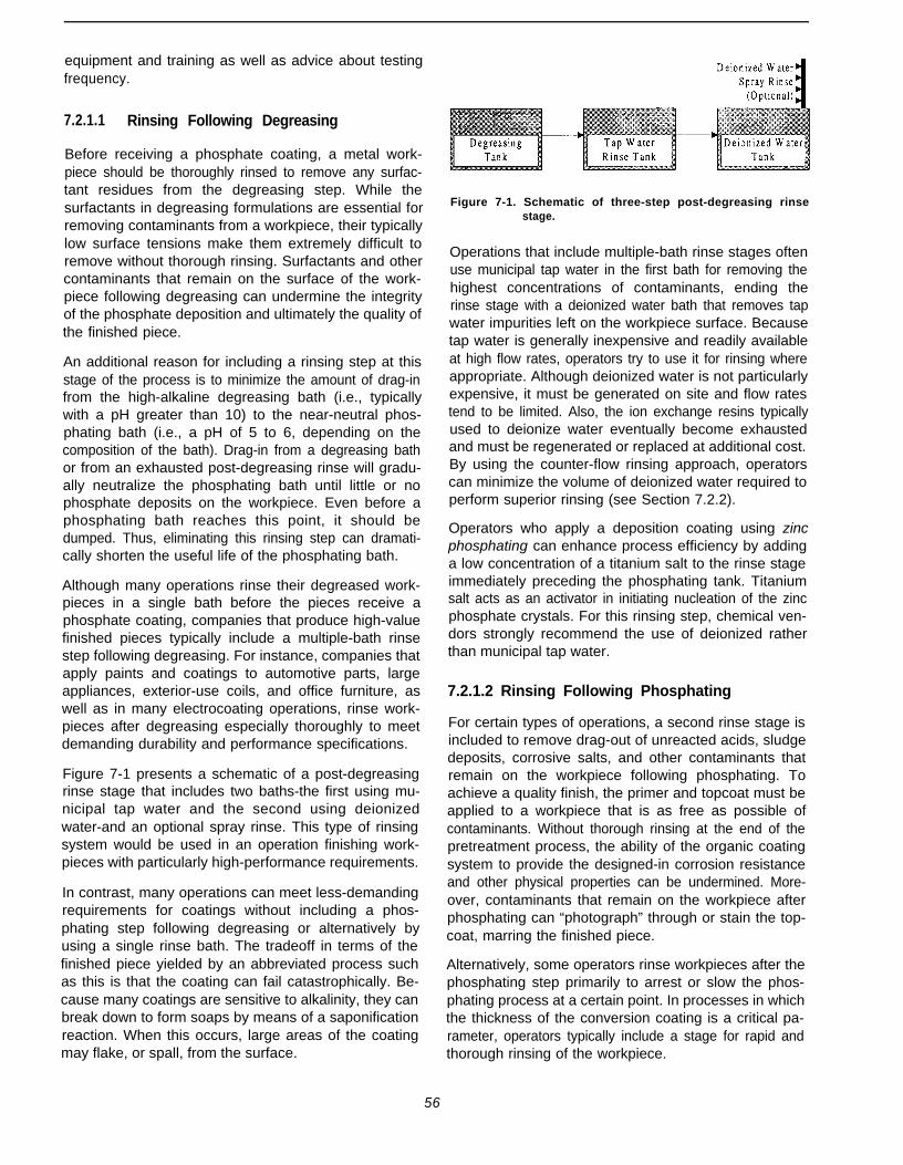
equipment and training as well as advice about testingfrequency.
7.2.1.1 Rinsing Following Degreasing
Before receiving a phosphate coating, a metal work-piece should be thoroughly rinsed to remove any surfac-tant residues from the degreasing step. While thesurfactants in degreasing formulations are essential forremoving contaminants from a workpiece, their typicallylow surface tensions make them extremely difficult toremove without thorough rinsing. Surfactants and othercontaminants that remain on the surface of the work-piece following degreasing can undermine the integrityof the phosphate deposition and ultimately the quality ofthe finished piece.
An additional reason for including a rinsing step at thisstage of the process is to minimize the amount of drag-infrom the high-alkaline degreasing bath (i.e., typicallywith a pH greater than 10) to the near-neutral phos-phating bath (i.e., a pH of 5 to 6, depending on thecomposition of the bath). Drag-in from a degreasing bathor from an exhausted post-degreasing rinse will gradu-ally neutralize the phosphating bath until little or nophosphate deposits on the workpiece. Even before aphosphating bath reaches this point, it should bedumped. Thus, eliminating this rinsing step can dramati-cally shorten the useful life of the phosphating bath.
Although many operations rinse their degreased work-pieces in a single bath before the pieces receive aphosphate coating, companies that produce high-valuefinished pieces typically include a multiple-bath rinsestep following degreasing. For instance, companies thatapply paints and coatings to automotive parts, largeappliances, exterior-use coils, and office furniture, aswell as in many electrocoating operations, rinse work-pieces after degreasing especially thoroughly to meetdemanding durability and performance specifications.
Figure 7-1 presents a schematic of a post-degreasingrinse stage that includes two baths-the first using mu-nicipal tap water and the second using deionizedwater-and an optional spray rinse. This type of rinsingsystem would be used in an operation finishing work-pieces with particularly high-performance requirements.
In contrast, many operations can meet less-demandingrequirements for coatings without including a phos-phating step following degreasing or alternatively byusing a single rinse bath. The tradeoff in terms of thefinished piece yielded by an abbreviated process suchas this is that the coating can fail catastrophically. Be-cause many coatings are sensitive to alkalinity, they canbreak down to form soaps by means of a saponificationreaction. When this occurs, large areas of the coatingmay flake, or spall, from the surface.
Figure 7-1. Schematic of three-step post-degreasing rinsestage.
Operations that include multiple-bath rinse stages oftenuse municipal tap water in the first bath for removing thehighest concentrations of contaminants, ending therinse stage with a deionized water bath that removes tapwater impurities left on the workpiece surface. Becausetap water is generally inexpensive and readily availableat high flow rates, operators try to use it for rinsing whereappropriate. Although deionized water is not particularlyexpensive, it must be generated on site and flow ratestend to be limited. Also, the ion exchange resins typicallyused to deionize water eventually become exhaustedand must be regenerated or replaced at additional cost.By using the counter-flow rinsing approach, operatorscan minimize the volume of deionized water required toperform superior rinsing (see Section 7.2.2).
Operators who apply a deposition coating using zincphosphating can enhance process efficiency by addinga low concentration of a titanium salt to the rinse stageimmediately preceding the phosphating tank. Titaniumsalt acts as an activator in initiating nucleation of the zincphosphate crystals. For this rinsing step, chemical ven-dors strongly recommend the use of deionized ratherthan municipal tap water.
7.2.1.2 Rinsing Following Phosphating
For certain types of operations, a second rinse stage isincluded to remove drag-out of unreacted acids, sludgedeposits, corrosive salts, and other contaminants thatremain on the workpiece following phosphating. Toachieve a quality finish, the primer and topcoat must beapplied to a workpiece that is as free as possible ofcontaminants. Without thorough rinsing at the end of thepretreatment process, the ability of the organic coatingsystem to provide the designed-in corrosion resistanceand other physical properties can be undermined. More-over, contaminants that remain on the workpiece afterphosphating can “photograph” through or stain the top-coat, marring the finished piece.
Alternatively, some operators rinse workpieces after thephosphating step primarily to arrest or slow the phos-phating process at a certain point. In processes in whichthe thickness of the conversion coating is a critical pa-rameter, operators typically include a stage for rapid andthorough rinsing of the workpiece.
56

In contrast to the detrimental effect that surface alkalinitycan have on a primer-topcoat system, a slightly acidicsurface enhances initial adhesion of the primer as wellas long-term corrosion resistance. Thus, for many op-erations, municipal tap water can be used for rinsing atthis stage. Although tap water has a slightly higher pHthan the phosphating chemicals, the rinse does not needto raise the pH of the workpiece surface to neutral (i.e.,pH 7.0). Most municipal water is unsuitable for usedirectly from the tap for operations coating workpiecesof especially high value. This is due to the presence ofimpurities (e.g., soluble and insoluble metal salts).Often, however, tap water is used for the initial step in amultiple-bath rinse stage. For high-value operations,deionized water is preferred for all subsequent rinsebaths.
Whereas a single rinse bath following degreasing maybe sufficient for some operations, the use of multiplebaths following phosphating is recommended for mostworkpieces. In general, a single post-phosphating rinsewould leave considerable residue on the workpiece asit passes through the dry-off oven and enters the primer-topcoat application stage. Thus, at a minimum, a secondrinse stage, preferably one that also functions as thesealing rinse (see Section 7.3), should be included formost paints and coatings processes. As with the de-greasing rinse, the counter-flow rinsing approach is aneffective method at this stage for maximizing processefficiency (see Section 7.2.2). Operations finishing high-value workpieces typically include a system of at leastthree post-phosphating rinses, two of which bathe thepiece in deionized water, followed by spray or mistrinsing with deionized water.
7.2.2 Counter-Flow Rinsing
As well as being an effective method for thoroughlywashing contaminants from workpieces after degreas-ing or phosphating, counter-flow rinsing is a particularlyeffective method for minimizing water usage. Nonethe-less, few managers of paints and coatings operationshave a sufficient understanding of this rinsing methodas a process control strategy.
Fundamentally, a counter-flow rinsing system is a se-quence of baths (i.e., two or more) in which replenishedrinse water moves in the opposite direction of the proc-ess flow. Thus, the workpiece progresses from dirtier tocleaner rinse water (Figure 7-2). The system maximizeswater use by replenishing the rinse at the final bath inthe sequence; overflow from each bath in the sequencein turn replenishes rinse water in the preceding bath.Rinse water effluent is ultimately released to the waste-water treatment system as overflow from the first (dirti-est) bath in the sequence. The basic concept behindcounter-flow rinsing is that the makeup water in the first
bath in a rinsing sequence does not need to be as cleanas that in the last.
The key to an effective rinse system based on thisapproach is maintaining the dilution ratio from the firstto the last bath in the counter-flow sequence. The dilu-tion ratio is primarily a factor of the system’s rinse waterflow rate versus the workpiece drag-in rate. For in-stance, if the degreasing tank has a chemical concen-tration of 1 lb/gal, then the workpiece will drag 1 lb/galof chemical into the first rinse tank. If that rinse tankholds 99 gallons of uncontaminated water, the chemicalconcentration of the tank with the 1 gallon of drag-in willbe 1 pound of chemical per 100 gallons of water; thus,the chemical concentration will be 0.01 lb/gal and thedilution ratio will be 100:1.
Related considerations, however, include the concentra-tion of contaminant in the makeup water replenishing abath and the contaminant concentration in the bath itself.Equations for calculating the rinse water flow rate andnumber of rinse baths required to achieve a specifieddilution ratio are provided and explained in Appendix B.
Controlling a system’s dilution ratio allows the operatorto take advantage of one of the principal benefits ofcounter-flow rinsing: reducing the overall volume ofwater required for cleaning a workpiece by adding baths.A single rinse bath quickly loses its effectiveness unlessrelatively large volumes of water are added to maintainthe dilution ratio. Figures 7-2 and 7-3 illustrate waterusage needs relative to time for maintaining a dilutionratio in a one-step rinse system of 1,000:1 gallons ofrinse water to contaminant. Based on this illustration, aone-step rinse for a workpiece with a drag-in rate of 1gal/min would consume large amounts of water. To beeffective, the process would require either a large-vol-ume tank or a small tank with rinse water changed (i.e.,dumped) frequently.
By comparing gallon-per-minute flow rates required toclean a workpiece with a 1 gal/min contaminant drag-inrate, Table 7-2 indicates the reduction in water use thatcan be realized by increasing the number of baths in acounter-flow rinsing system. Thus, Table 7-2 shows thatwhen a process’s dilution ratio is 100:1, adding a secondbath reduces the flow rate requirement from 99 to 9.5gal/min. The operator of this system would reduce thewater requirement to 2.3 gal/min by adding a fifth rinsebath. Note that for a dilution ratio of 20,000:1 (requiredfor some particularly high-value workpieces), the flowrate specified for a five-bath system is 7.0 gal/min, whichis only about three times the rate for a 100:1 dilution rate.Table 7-3 provides another perspective on the processefficiency advantages of counter-flow rinsing by pre-senting water flow rates in terms of percentage reduc-tions between additional baths. For example (based onthe data in Table 7-2), with a dilution ratio of 100:1 for aworkpiece with a 1 gal/min drag-in, the flow rate reduc-
57
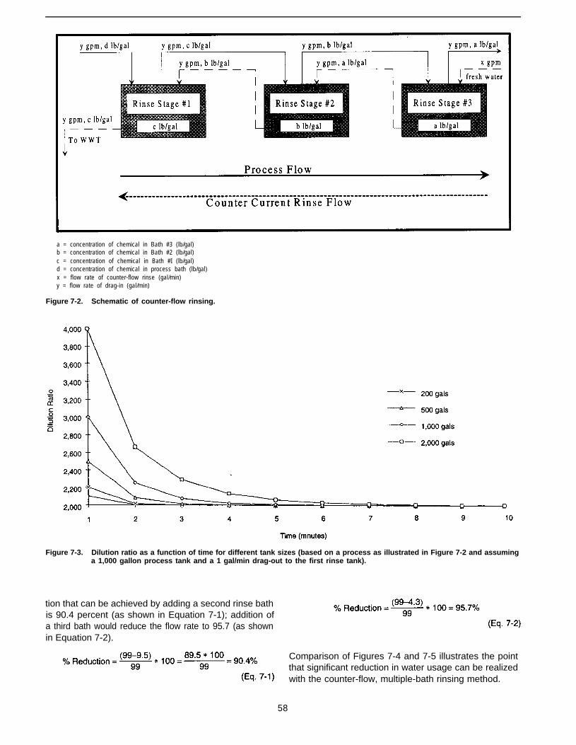
a = concentration of chemical in Bath #3 (lb/gal)b = concentration of chemical in Bath #2 (lb/gal)c = concentration of chemical in Bath #I (lb/gal)d = concentration of chemical in process bath (lb/gal)x = flow rate of counter-flow rinse (gal/min)y = flow rate of drag-in (gal/min)
Figure 7-2. Schematic of counter-flow rinsing.
Figure 7-3. Dilution ratio as a function of time for different tank sizes (based on a process as illustrated in Figure 7-2 and assuminga 1,000 gallon process tank and a 1 gal/min drag-out to the first rinse tank).
tion that can be achieved by adding a second rinse bathis 90.4 percent (as shown in Equation 7-1); addition ofa third bath would reduce the flow rate to 95.7 (as shownin Equation 7-2).
Comparison of Figures 7-4 and 7-5 illustrates the pointthat significant reduction in water usage can be realizedwith the counter-flow, multiple-bath rinsing method.
58
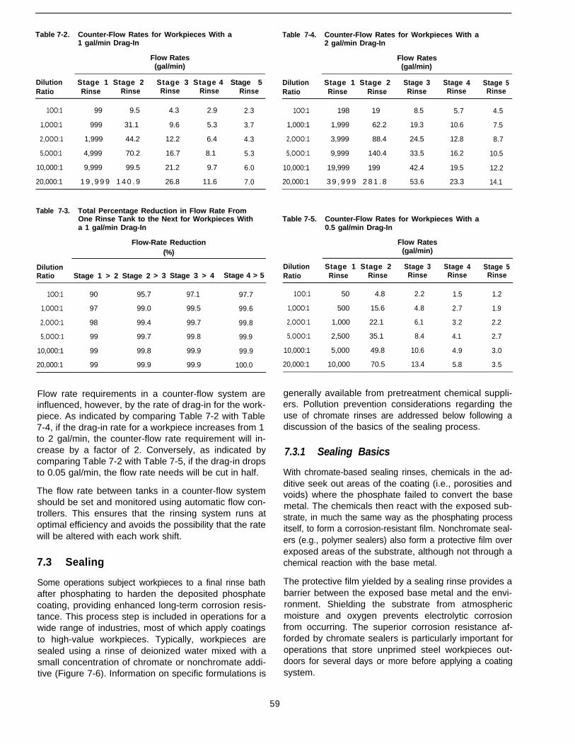
Table 7-2. Counter-Flow Rates for Workpieces With a1 gal/min Drag-In
Flow Rates(gal/min)
Dilution Stage 1 Stage 2 Stage 3 Stage 4 Stage 5Ratio Rinse Rinse Rinse Rinse Rinse
1OO:1 99 9.5 4.3 2.9 2.3
1,OOO:1 999 31.1 9.6 5.3 3.7
2,OOO:1 1,999 44.2 12.2 6.4 4.3
5,OOO:1 4,999 70.2 16.7 8.1 5.3
10,000:1 9,999 99.5 21.2 9.7 6.0
20,000:1 1 9 , 9 9 9 1 4 0 . 9 26.8 11.6 7.0
Table 7-3. Total Percentage Reduction in Flow Rate FromOne Rinse Tank to the Next for Workpieces Witha 1 gal/min Drag-In
Flow-Rate Reduction(%)
DilutionRatio Stage 1 > 2 Stage 2 > 3 Stage 3 > 4 Stage 4 > 5
1OO:1 90 95.7 97.1 97.7
1,OOO:1 97 99.0 99.5 99.6
2,OOO:1 98 99.4 99.7 99.8
5,OOO:1 99 99.7 99.8 99.9
10,000:1 99 99.8 99.9 99.9
20,000:1 99 99.9 99.9 100.0
Flow rate requirements in a counter-flow system areinfluenced, however, by the rate of drag-in for the work-piece. As indicated by comparing Table 7-2 with Table7-4, if the drag-in rate for a workpiece increases from 1to 2 gal/min, the counter-flow rate requirement will in-crease by a factor of 2. Conversely, as indicated bycomparing Table 7-2 with Table 7-5, if the drag-in dropsto 0.05 gal/min, the flow rate needs will be cut in half.
The flow rate between tanks in a counter-flow systemshould be set and monitored using automatic flow con-trollers. This ensures that the rinsing system runs atoptimal efficiency and avoids the possibility that the ratewill be altered with each work shift.
7.3 Sealing
Some operations subject workpieces to a final rinse bathafter phosphating to harden the deposited phosphatecoating, providing enhanced long-term corrosion resis-tance. This process step is included in operations for awide range of industries, most of which apply coatingsto high-value workpieces. Typically, workpieces aresealed using a rinse of deionized water mixed with asmall concentration of chromate or nonchromate addi-tive (Figure 7-6). Information on specific formulations is
Table 7-4. Counter-Flow Rates for Workpieces With a2 gal/min Drag-In
Flow Rates(gal/min)
Dilution Stage 1 Stage 2 Stage 3 Stage 4 Stage 5Ratio Rinse Rinse Rinse Rinse Rinse
1OO:1 198 19 8.5 5.7 4.5
1,000:1 1,999 62.2 19.3 10.6 7.5
2,OOO:1 3,999 88.4 24.5 12.8 8.7
5,OOO:1 9,999 140.4 33.5 16.2 10.5
10,000:1 19,999 199 42.4 19.5 12.2
20,000:1 3 9 , 9 9 9 2 8 1 . 8 53.6 23.3 14.1
Table 7-5. Counter-Flow Rates for Workpieces With a0.5 gal/min Drag-In
Flow Rates(gal/min)
Dilution Stage 1 Stage 2 Stage 3 Stage 4 Stage 5Ratio Rinse Rinse Rinse Rinse Rinse
1OO:1 50 4.8 2.2 1.5 1.2
1,OOO:1 500 15.6 4.8 2.7 1.9
2,OOO:1 1,000 22.1 6.1 3.2 2.2
5,OOO:1 2,500 35.1 8.4 4.1 2.7
10,000:1 5,000 49.8 10.6 4.9 3.0
20,000:1 10,000 70.5 13.4 5.8 3.5
generally available from pretreatment chemical suppli-ers. Pollution prevention considerations regarding theuse of chromate rinses are addressed below following adiscussion of the basics of the sealing process.
7.3.1 Sealing Basics
With chromate-based sealing rinses, chemicals in the ad-ditive seek out areas of the coating (i.e., porosities andvoids) where the phosphate failed to convert the basemetal. The chemicals then react with the exposed sub-strate, in much the same way as the phosphating processitself, to form a corrosion-resistant film. Nonchromate seal-ers (e.g., polymer sealers) also form a protective film overexposed areas of the substrate, although not through achemical reaction with the base metal.
The protective film yielded by a sealing rinse provides abarrier between the exposed base metal and the envi-ronment. Shielding the substrate from atmosphericmoisture and oxygen prevents electrolytic corrosionfrom occurring. The superior corrosion resistance af-forded by chromate sealers is particularly important foroperations that store unprimed steel workpieces out-doors for several days or more before applying a coatingsystem.
59
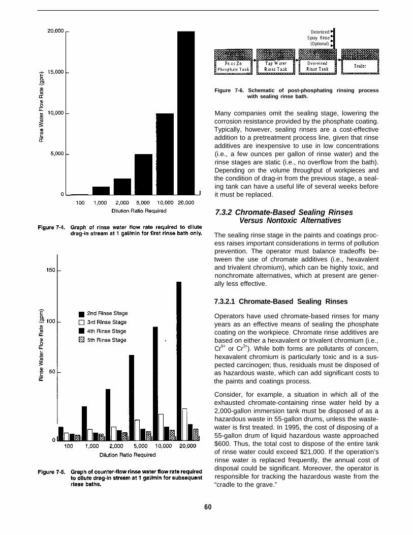
60
DeionizedSpray Rinse
(Optional)
Figure 7-6. Schematic of post-phosphating rinsing processwith sealing rinse bath.
Many companies omit the sealing stage, lowering thecorrosion resistance provided by the phosphate coating.Typically, however, sealing rinses are a cost-effectiveaddition to a pretreatment process line, given that rinseadditives are inexpensive to use in low concentrations(i.e., a few ounces per gallon of rinse water) and therinse stages are static (i.e., no overflow from the bath).Depending on the volume throughput of workpieces andthe condition of drag-in from the previous stage, a seal-ing tank can have a useful life of several weeks beforeit must be replaced.
7.3.2 Chromate-Based Sealing RinsesVersus Nontoxic Alternatives
The sealing rinse stage in the paints and coatings proc-ess raises important considerations in terms of pollutionprevention. The operator must balance tradeoffs be-tween the use of chromate additives (i.e., hexavalentand trivalent chromium), which can be highly toxic, andnonchromate alternatives, which at present are gener-ally less effective.
7.3.2.1 Chromate-Based Sealing Rinses
Operators have used chromate-based rinses for manyyears as an effective means of sealing the phosphatecoating on the workpiece. Chromate rinse additives arebased on either a hexavalent or trivalent chromium (i.e.,Cr6+ or Cr3+). While both forms are pollutants of concern,hexavalent chromium is particularly toxic and is a sus-pected carcinogen; thus, residuals must be disposed ofas hazardous waste, which can add significant costs tothe paints and coatings process.
Consider, for example, a situation in which all of theexhausted chromate-containing rinse water held by a2,000-gallon immersion tank must be disposed of as ahazardous waste in 55-gallon drums, unless the waste-water is first treated. In 1995, the cost of disposing of a55-gallon drum of liquid hazardous waste approached$600. Thus, the total cost to dispose of the entire tankof rinse water could exceed $21,000. If the operation’srinse water is replaced frequently, the annual cost ofdisposal could be significant. Moreover, the operator isresponsible for tracking the hazardous waste from the“cradle to the grave.”

Alternatively, the wastewater could be discharged to anonsite treatment plant for removal of the chromates andother contaminants by precipitation and filtration. Theresulting sludge material would then need to be properlydisposed of. The treated water could be recycled to therinsing operation. While this approach is usually costeffective for large operations, most medium- and small-sized operations cannot afford the cost of an onsitetreatment plant.
Another limitation of chromate use is that some formu-lations require that the workpiece be rinsed with cleanwater after the sealing rinse to remove unreacted chro-mate salts. Along with the cost of any equipment asso-ciated with adding this process step, costs associatedwith the generation of additional wastewater must beconsidered. One approach to minimizing the cost of thisrinse step is to spray wash the workpiece while it issuspended over the sealing rinse bath. The tradeoff withthis approach is that the spray rinse water is likely togradually alter the chromate dilution ratio, limiting theuseful life of the bath.
Given the limitations associated with the use of chro-mate-based rinse formulations, operators need to care-fully weigh tradeoffs in terms of costs, pollutionprevention, and the durability requirements of the fin-ished workpiece. The determination of which sealingformulation to use must be made on a process-specificbasis after thorough testing of various options.
7.3.2.2 Nonchromate Sealing Rinses
Although several nonchromate sealing formulationshave been developed, their effectiveness for enhancingthe durability of a finished workpiece as compared withchromate-based sealers has yet to be fully established(3). Nonetheless, when the finished workpiece will be usedin applications requiring less-demanding corrosion re-sistance, nonchromate sealers can present an-attractivealternative. Also, available high-performance coatings(e.g., epoxies and polyurethanes) have corrosion-resis-tance properties that allow operators to offset potentialdeficiencies associated with nonchomate sealers.
The great advantage that nonchromate sealers holdover chromate-based formulations is that they are non-toxic. Thus, an operator can realize significant benefitsby reducing or eliminating the need to dispose of haz-ardous residuals.
A related advantage is that often no clean-water rinsingof the workpiece needs to be performed after use of anonchromate sealer. Indeed, post-sealing rinsing mayharm the workpiece because it can wash away theprotective film on the piece’s surface. Thus, an operatorcan realize process savings in terms of wastewaterminimization.
When determining whether to use a nonchromatesealer, the operator needs to weigh these potential ad-vantages against the quality requirements of the fin-ished workpiece. Before incorporating a nontoxic sealerinto a paints and coatings process, an operator shouldthoroughly test the formulation in terms of the work-piece’s specifications.
7.4 Case Example
Navistar International Transportation Corp., a manufac-turer of truck cabs, has reported on its program tominimize pollution of all media (4). The truck cabs enterthe pretreatment process via a two-stage alkaline de-greaser. Stage 1 operates optimally at a pH of 10.5 andwith an alkalinity range of 6 to 10. When analyticaltesting finds the total alkalinity to fall below 6, the de-greaser is no longer considered effective. Formerly atthis point, a portion of the tank would be dumped. Tooptimize the performance of Stage 1, the manufacturerwould allow 2.5 gal/min of contaminated tap water fromStage 2 to overflow into Stage 1 while allowing an equalamount of water displaced from Stage 1 to overflow tothe wastewater treatment system. In addition, the manu-facturer would flush approximately 2,000 gal of waterfrom the tank every 7 days, discharging it to the waste-water treatment system. Finally, every 45 days, Navistardumped the entire contents of Stage 1, rinsed the tankwith up to 17,000 gal of water, and then filled it with halfthe contents in Stage 2.
After examining the system further, Navistar discoveredthat it was not cost effective to cross-contaminate Stage1 with water in Stage 2. Rather, after dumping, Navistarused fresh chemicals and water, extending the life ofboth stages from 45 to 90 days. Total cost savings forthese modifications amounted to $9,384 per month.
Stage 3 of its pretreatment process comprises a munici-pal tap water rinse, which is contaminated with drag-infrom the alkaline degreasing Stages 1 and 2. Navistardiscovered that by allowing the cabs to drip drain overStage 2 for an additional 1/2 minute, it could realizesignificant savings in the tap water rinse of Stage 3.Previously, Navistar had dumped this stage arbitrarily ona 14-day schedule. After performing process controllaboratory tests on the alkalinity of the bath, however, itwas able to decrease the dumping schedule to every 30days. Apparently, this resulted in a 50-percent reductionof contaminated water sent to the wastewater treatmentsystem.
Navistar performed a similar modification regarding thepost-phosphating rinse stage. Process line operatorshad been arbitrarily dumping Stage 6 on a 14-dayschedule. They found, however, that by monitoring thelevel of contaminants in this stage, they could decreasethe frequency of dumping to between 90 and 120 days.
61
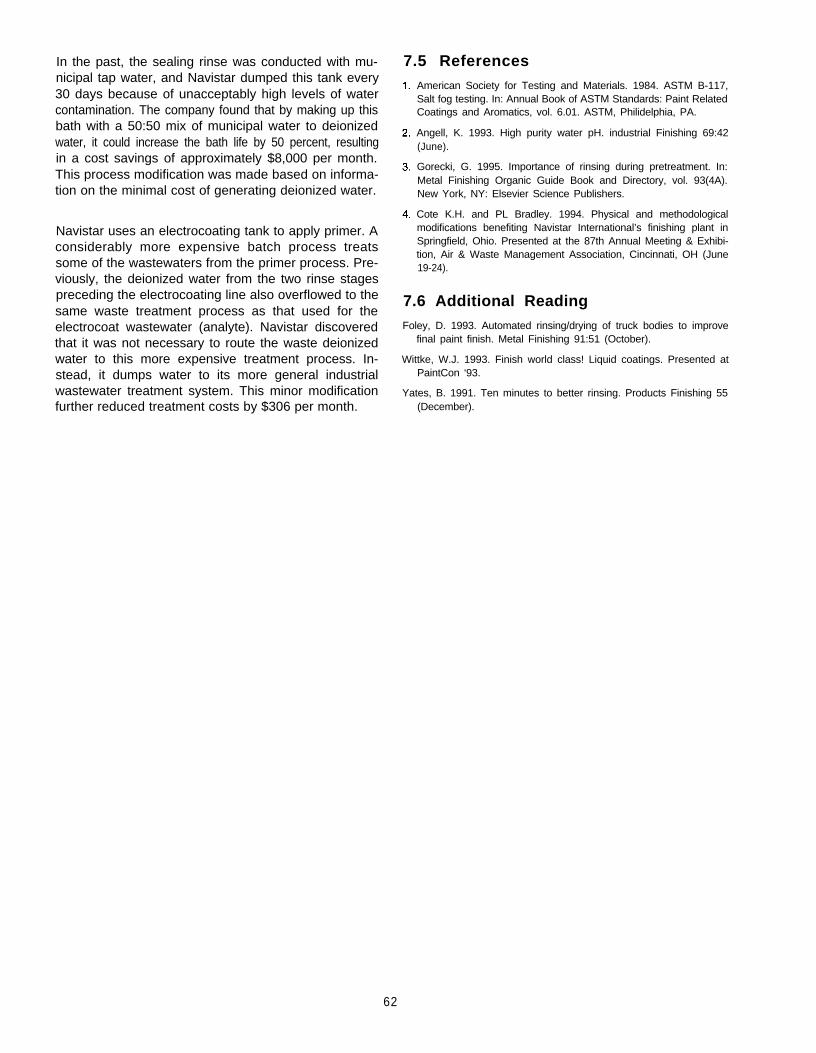
In the past, the sealing rinse was conducted with mu-nicipal tap water, and Navistar dumped this tank every30 days because of unacceptably high levels of watercontamination. The company found that by making up thisbath with a 50:50 mix of municipal water to deionizedwater, it could increase the bath life by 50 percent, resultingin a cost savings of approximately $8,000 per month.This process modification was made based on informa-tion on the minimal cost of generating deionized water.
Navistar uses an electrocoating tank to apply primer. Aconsiderably more expensive batch process treatssome of the wastewaters from the primer process. Pre-viously, the deionized water from the two rinse stagespreceding the electrocoating line also overflowed to thesame waste treatment process as that used for theelectrocoat wastewater (analyte). Navistar discoveredthat it was not necessary to route the waste deionizedwater to this more expensive treatment process. In-stead, it dumps water to its more general industrialwastewater treatment system. This minor modificationfurther reduced treatment costs by $306 per month.
7.5 ReferencesAmerican Society for Testing and Materials. 1984. ASTM B-117,Salt fog testing. In: Annual Book of ASTM Standards: Paint RelatedCoatings and Aromatics, vol. 6.01. ASTM, Philidelphia, PA.
Angell, K. 1993. High purity water pH. industrial Finishing 69:42(June).
Gorecki, G. 1995. Importance of rinsing during pretreatment. In:Metal Finishing Organic Guide Book and Directory, vol. 93(4A).New York, NY: Elsevier Science Publishers.
Cote K.H. and PL Bradley. 1994. Physical and methodologicalmodifications benefiting Navistar International’s finishing plant inSpringfield, Ohio. Presented at the 87th Annual Meeting & Exhibi-tion, Air & Waste Management Association, Cincinnati, OH (June19-24).
7.6 Additional ReadingFoley, D. 1993. Automated rinsing/drying of truck bodies to improve
final paint finish. Metal Finishing 91:51 (October).
Wittke, W.J. 1993. Finish world class! Liquid coatings. Presented atPaintCon ‘93.
Yates, B. 1991. Ten minutes to better rinsing. Products Finishing 55(December).
62
Chapter 8Abrasive Blast Cleaning of Metal Surfaces: Process Efficiency
8.1 Introduction
8.1.1 Pollution Prevention Considerations
Abrasive blasting is widely used in the paints and coat-ings industry as a means of cleaning metal workpiecesand preformed materials. If blast cleaning operationsare not carefully implemented and monitored, however,quality control problems can result that undermine proc-ess efficiency and lead to excess waste. A critical factorin blast cleaning is selection of an abrasive media thatwill yield a blast profile appropriate to the thickness ofthe primer coating. When an abrasive raises peaks onthe substrate that protrude through the coating, flashrusting can result, especially if primed workpieces aretemporarily stored outdoors. Rusting generally necessi-tates the reworking of pieces, adding process costsassociated with material, labor, and waste management.
An efficiently run blasting operation also can yield proc-ess savings related to the cleaning media. Similar toaqueous degreasing operations, most of the dry mediaused in abrasive blasting can be recycled. Indeed, manyoperations include a degreasing step in the process lineto maximize the blast media’s reuse potential. By reus-ing abrasives, an operator can minimize the generationof the significant amounts of waste represented by spentmedia. Other variations include adding a phosphatingstep for further enhancing mechanical adhesion of thecoating system.
Compared with degreasing, the abrasive blasting proc-ess can be time consuming and labor intensive; more-over, blasting can involve the risk of warping theworkpiece. Thus, facility operators generally opt for thiscleaning approach only when workpieces are too largeto be immersed or effectively sprayed with a degreasingformulation. An incidental benefit of abrasive blasting,however, is that the considerable volume of wastewatergenerated with other cleaning methods is avoided.
These pollution prevention considerations are pre-sented in this chapter in the context of process effi-ciency. An important overriding consideration in thisdiscussion is right-first-time processing, which calls fordesigning and monitoring operations to ensure that re-
works, and associated costs and pollutants, are mini-mized.
8.1.2 Decision-Making Criteria
Decision-making criteria relevant to process efficiencyin the abrasive blast cleaning of metal surfaces, asaddressed in this chapter, are highlighted in Table 8-1.
8.2 Process Basics
8.2-1 Introduction
Abrasive blasting is a method of cleaning corrosion andother contaminants from previously uncoated metal sub-strates before applying a primer-topcoat system. Blastcleaning also is used to remove failed or aged coatingsfrom substrates before repainting (i.e., paint stripping),as discussed in Chapter 14.
In abrasive blasting, mineral and metallic abrasives,such as steel shot or mineral grit, are directed or pro-pelled from a hose at a substrate using a high-pressurepneumatic system (Figure 8-1). The line operator holdsthe blasting nozzle a few inches from the substrate whiledirecting the blast to all areas of the workpiece.
As a cleaning approach for substrates that have notbeen previously painted, abrasive blasting is used pri-marily for workpieces that are too large and heavy to bepretreated using immersion or spray degreasing proc-esses.’ Nonetheless, many operations degrease work-pieces to the extent possible before subjecting them toblasting in order to minimize contamination of an abra-sive media that will be recycled. Even when abrasiveblasting is used in conjunction with a degreasing or aphosphating stage (see Section 8.4 on process vari-ations), the operator is likely to realize some incidentalbenefits in terms of lower water-use requirements andthus lower wastewater generation.
1 As noted in Chapter 5, “degreasing” is used generally in this docu-ment to refer to the various liquid/vapor methods used in paints andcoatings operations to clean substrates. The author recognizes thatsome operators use the term degreasing to refer specifically to vapordegreasing.
63
Table 8-1. Decision-Making Criteria Regarding Abrasive Blasting Processes
Issue Considerations
Do workpieces have a steelsubstrate of sufficient thickness(>14 gage) to allow for abrasiveblasting without warping surface?
Do workpieces need to be blastcleaned even though they havesections of thin steel substrate(<74 gage)?
Will a liquid primer be applied?
Will a zinc-rich primer be applied l If so, workpieces should not undergo phosphating or wash priming; to be effective the zinc-richto workpieces? primer must be in direct contact with the metal surface.
Can the operator select from arange of abrasives?
Are workpieces currentlydegreased prior to abrasiveblasting?
l If so, consideration should be given to this approach as an alternative to pretreating workpieces witha chemical process.
l If so, it might be necessary to use a fine-mesh abrasive and to experiment with different blastingpressures to avoid warping the workpiece.
l If so, select an abrasive (or blend of abrasives) that will yield a blast profile that can be completelycovered by the film thickness of the coating. An angular profile, for instance, can be particularlydifficult to cover and may require a second coat of primer.
l Workpieces should be primed within 4 hours (but not longer than 8 hours) after abrasive blasting,depending on the ambient environment. For example, if blasted workpieces will be exposed to amarine or chemical environment, the interval should be shortened to avoid the onset of corrosion.
l Consideration should be given to degreasing workpieces before blasting so that the abrasive mediacan be kept clean for recycling in the blasting process.
l The use of wash primers, which tend to have a high VOCs content, should be avoided as a pollutionprevention measure.
l Given the importance of establishing direct contact between the primer and the substrate,workpieces should be degreased prior to blasting.
l The blast profile should be sufficient (1.5 to 2.5 mils) to facilitate good mechanical adhesion betweenthe primer and the substrate. (It is strongly recommended that the operator consult with a vendorwhen establishing the profile specification.)
l Because workpieces receiving a zinc-rich primer are likely to provide corrosion resistance inaggressive environments, they should be cleaned to a near-white or white metal finish.
l If so, an abrasive with the lowest dusting characteristics and the highest recycle rate should beselected. (It may be necessary to consult with a vendor when choosing an abrasive.)
l Consideration should be given to degreasing workpieces before blasting so that the abrasive mediacan be kept clean for recycling in the blasting process.
l Without including a degreasing stage, abrasives can transfer contaminants from one workpiece toanother and even imbed them in the substrate.
Abrasive blasting is used primarily to remove such sur-face contaminants as carbon deposits, scale, chemicalimpurities, and rust as well as oil and grease. lt also canbe used, however, to physically alter the surface of aworkpiece to encourage good adhesion between thecoating system and the substrate. For example, an op-erator might blast a metal surface with an abrasive toaccomplish the following:
l Create a surface profile for optimum coating adhesion.
l Reduce design weights, porosity, friction, or suscep-tibility to corrosion.
l Strengthen the surface by peening.
l Add fatigue resistance.
l Remove surface irregularities.
l Correct distortions.
The discussion in this chapter, however, primarily fo-cuses on blast cleaning. For more detailed discussions
about other uses of abrasive blasting, see References1,2, and 3.
8.2.2 Abrasive Blasting Systems
Blast cleaning is conducted using a pneumatic systemthat mixes the abrasive media and pressurized airthrough a valve at the base of the unit. Typically, sys-tems force the media out the blasting nozzle with 100psi of pressure (4); the speed at which the media travelis directly related to particle mass. Thus, the blastingefficiency of a particular media can be determined usingthe following equation, which relates mass to kineticenergy and velocity (5):
Impact energy = ½ mass x velocity*
Based on this equation, if mass is doubled, impactenergy is also doubled. Similarly, if air pressure is in-creased, velocity also increases. Thus, if the media’svelocity is doubled, the impact energy is quadrupled.Given that the production rate is proportional to theimpact energy, if the impact energy is quadrupled, then
64
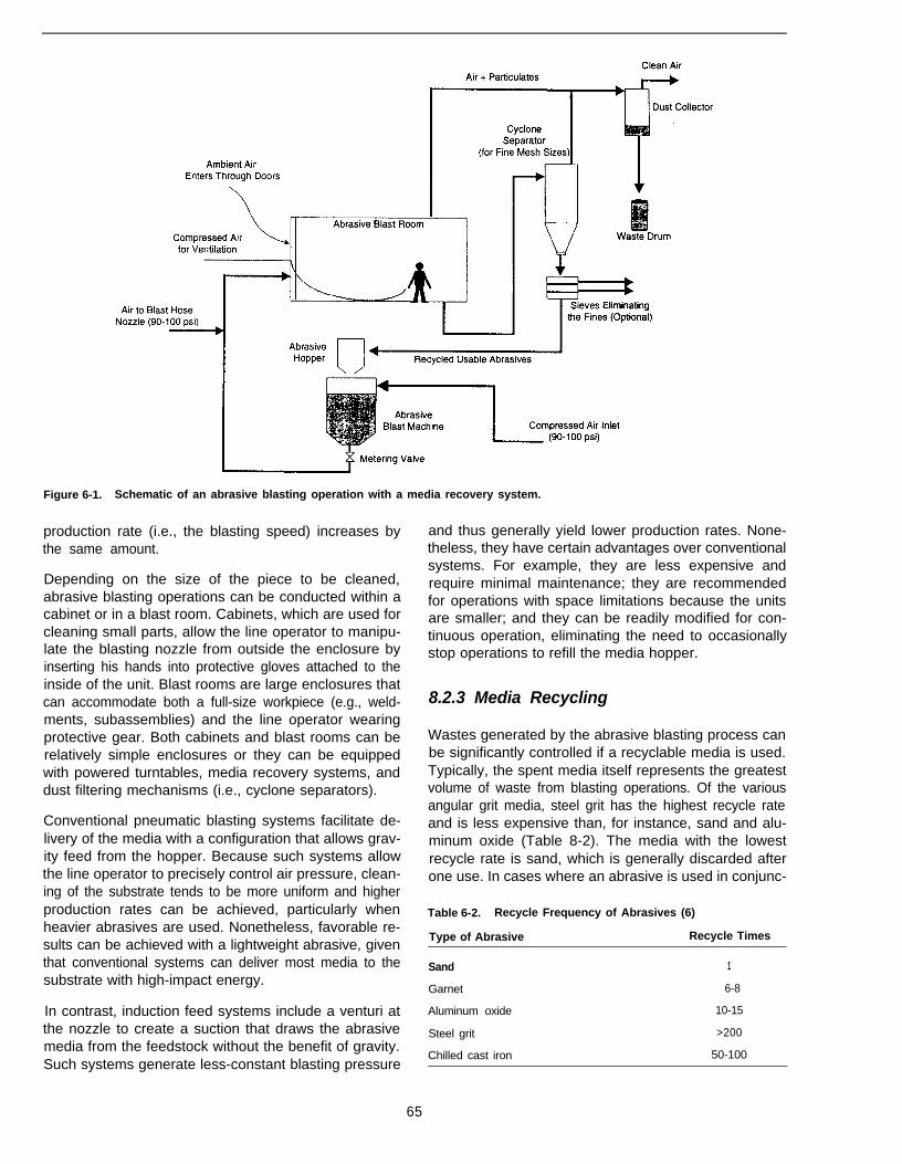
Figure 6-1. Schematic of an abrasive blasting operation with a media recovery system.
production rate (i.e., the blasting speed) increases bythe same amount.
Depending on the size of the piece to be cleaned,abrasive blasting operations can be conducted within acabinet or in a blast room. Cabinets, which are used forcleaning small parts, allow the line operator to manipu-late the blasting nozzle from outside the enclosure byinserting his hands into protective gloves attached to theinside of the unit. Blast rooms are large enclosures thatcan accommodate both a full-size workpiece (e.g., weld-ments, subassemblies) and the line operator wearingprotective gear. Both cabinets and blast rooms can berelatively simple enclosures or they can be equippedwith powered turntables, media recovery systems, anddust filtering mechanisms (i.e., cyclone separators).
Conventional pneumatic blasting systems facilitate de-livery of the media with a configuration that allows grav-ity feed from the hopper. Because such systems allowthe line operator to precisely control air pressure, clean-ing of the substrate tends to be more uniform and higherproduction rates can be achieved, particularly whenheavier abrasives are used. Nonetheless, favorable re-sults can be achieved with a lightweight abrasive, giventhat conventional systems can deliver most media to thesubstrate with high-impact energy.
In contrast, induction feed systems include a venturi atthe nozzle to create a suction that draws the abrasivemedia from the feedstock without the benefit of gravity.Such systems generate less-constant blasting pressure
and thus generally yield lower production rates. None-theless, they have certain advantages over conventionalsystems. For example, they are less expensive andrequire minimal maintenance; they are recommendedfor operations with space limitations because the unitsare smaller; and they can be readily modified for con-tinuous operation, eliminating the need to occasionallystop operations to refill the media hopper.
8.2.3 Media Recycling
Wastes generated by the abrasive blasting process canbe significantly controlled if a recyclable media is used.Typically, the spent media itself represents the greatestvolume of waste from blasting operations. Of the variousangular grit media, steel grit has the highest recycle rateand is less expensive than, for instance, sand and alu-minum oxide (Table 8-2). The media with the lowestrecycle rate is sand, which is generally discarded afterone use. In cases where an abrasive is used in conjunc-
Table 6-2. Recycle Frequency of Abrasives (6)
Type of Abrasive Recycle Times
Sand 1
Garnet 6-8
Aluminum oxide 10-15
Steel grit >200
Chilled cast iron 50-100
65
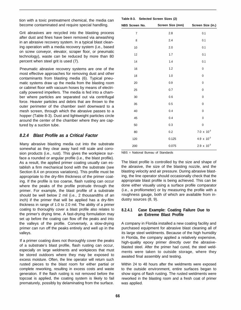
tion with a toxic pretreatment chemical, the media canbecome contaminated and require special handling.
Grit abrasives are recycled into the blasting processafter dust and fines have been removed via airwashingin an abrasive recovery system. In a typical blast clean-ing operation with a media recovery system (i.e., basedon screw conveyor, elevator, scraper floor, or pneumatictechnology), waste can be reduced by more than 80percent when steel grit is used (7).
Pneumatic abrasive recovery systems are one of themost effective approaches for removing dust and othercontaminants from blasting media (6). Typical pneu-matic systems draw up the media from the blasting roomor cabinet floor with vacuum hoses by means of electri-cally powered impellers. The media is fed into a cham-ber where particles are separated out via centrifugalforce. Heavier particles and debris that are thrown to theouter perimeter of the chamber swirl downward to amesh screen, through which the abrasive passes to ahopper (Table 8-3). Dust and lightweight particles circlearound the center of the chamber where they are cap-tured by a suction tube.
8.2.4 Blast Profile as a Critical Factor
Many abrasive blasting media cut into the substratesomewhat as they clear away hard mill scale and corro-sion products (i.e., rust). This gives the workpiece sur-face a rounded or angular profile (i.e., the blast profile).As a result, the applied primer coating usually can es-tablish a firm mechanical bond with the substrate (seeSection 8.4 on process variations). This profile must beappropriate to the dry-film thickness of the primer coat-ing. If the profile is too coarse, flash rusting can occurwhere the peaks of the profile protrude through theprimer. For example, the blast profile of a substrateshould be well below 2 mil (i.e., 2 thousandths of aninch) if the primer that will be applied has a dry-filmthickness in range of 1.0 to 2.0 mil. The ability of a primercoating to thoroughly cover a blast profile also relates tothe primer’s drying time. A fast-drying formulation mayset up before the coating can flow off the peaks and intothe valleys of the profile. Conversely, a slow-dryingprimer can run off the peaks entirely and well up in thevalleys.
If a primer coating does not thoroughly cover the peaksof a substrate’s blast profile, flash rusting can occur,especially on large weldments and workpieces that mustbe stored outdoors where they may be exposed toexcess moisture. Often, the line operator will return suchrusted pieces to the blast room for either partial orcomplete reworking, resulting in excess costs and wastegeneration. If the flash rusting is not removed before thetopcoat is applied, the coating system is likely to failprematurely, possibly by delaminating from the surface.
Table 8-3. Selected Screen Sizes (2)
NBS Screen No. Screen Size (mm) Screen Size (in.)
7 2.8 0.1
8 2.4 0.1
10 2.0 0.1
12 1.7 0.1
14 1.4 0.1
16 1.2 0
18 1.0 0
20 0.9 0
25 0.7 0
30 0.6 0
35 0.5 0
40 0.4 0
45 0.4 0
50 0.3 0
80 0.2 7.0 x 10⁻³
120 0.125 4.9 x 10⁻³
200 0.075 2.9 x 10⁻³
NBS = National Bureau of Standards
The blast profile is controlled by the size and shape ofthe abrasive, the size of the blasting nozzle, and theblasting velocity and air pressure. During abrasive blast-ing, the line operator should occasionally check that theappropriate blast profile is being achieved. This can bedone either visually using a surface profile comparator(i.e., a profilometer) or by measuring the profile with aroughness gauge, both of which are available from in-dustry sources (8, 9).
8.2.4.1 Case Example: Coating Failure Due toan Extreme Blast Profile
A company in Florida installed a new coating facility andpurchased equipment for abrasive blast cleaning all ofits large steel weldments. Because of the high humidityin Florida, the company applied a relatively expensive,high-quality epoxy primer directly over the abrasive-blasted steel. After the primer had cured, the steel weld-ments were taken to outside storage, where theyawaited final assembly and testing.
Within 24 to 48 hours after the weldments were exposedto the outside environment, entire surfaces began toshow signs of flash rusting. The rusted weldments werereworked in the blasting room and a fresh coat of primerwas applied.
66
An inspection of the substrate using a low-power mag-nifying glass showed that the peaks of the blast profilewere protruding through the primer. The profile wasmeasured at 2.5 to 3.5 mil and the primer dry-film thick-ness at only 0.8 to 1.0 mil.
The problem was then solved by changing the applica-tion parameters, which favored a shallower profile. Al-though this process change made the blasting operationmore time consuming and labor intensive, costs weremore than offset by avoiding the reworking of rustedweldments. Changing the application parameters re-quired no major management decision.
Although the company had carefully planned operationsat the new facility and specifications had called for ablast profile less than 1.5 mil, no quality control checksof the blasting process were conducted. Thus, no onenoticed that the profile was out of specification. Theproblem could have been avoided had better manage-ment practices been enforced.
The corrective action was taken to resolve a qualitycontrol problem, but the operation also benefited byminimizing pollution generation associated with rework-ing the weldments. This was an important unanticipatedbenefit, especially because the company operated in anarea with strict local environmental requirements.
8.2.5 Types of Abrasive Media and SelectionCriteria
The six most commonly used abrasive media are (6):
l Steel shot: Small, spherical particles of hypereutec-toid steel (i.e., containing more than 0.8 percent carb-on) in its fully heat-treated condition. Steel shot hasa uniform structure of finely tempered martensite (i.e.,the hard constituent of quenched steel), which pro-vides optimum resilience and resistance to fatigue.Thus, it is particularly suited to shot peening andconsidered an optimum abrasive for wheel blast ap-plications.
l Cast steel grit: A high-carbon content, angular pellet.Depending on the hardness selection, this abrasiveis effective, for instance, in removing scale or etchingthe substrate to enhance its profile. Steel grit is oneof the most commonly used abrasives for preparingsteel substrates to receive a coating (6).
l Aluminum oxide: Fused alumina grains that are an-gular and characteristically hard and resilient, provid-ing particularly fast cutting action.
l Garnet grit: A mineral abrasive with sharp angularcharacteristics that provides fast cutting action andhas a long service life.
Mineral slag: A diamond-like, angular abrasive that iswithout free silica and does not attract moisture, pro-viding fast cutting action.
Chilled iron grit: The lowest cost mineral abrasive. Itis particularly recommended for difficult cleaning jobs.
G/ass beads: Small, lightweight, spherical mediaused primarily on nonferrous metals for shot peeningand surface finishing. Predominantly used in the air-craft and automotive industries.
Table 8-4 lists selection criteria specific to various abra-sive blasting media. For some blasting operations, as-sorted abrasives are mixed so that the media includedifferent grit sizes. More general factors that the opera-tor should consider when choosing an abrasive includethe following:
Compatibility: The mineral or metallic abrasive shouldhave characteristics similar to the metal substrate toavoid the likelihood that galvanic corrosion will resultif some of the blasting material becomes imbeddedin the surface of the workpiece. For example, a steelabrasive should not be used on an aluminum sub-strate. Moreover, too hard an abrasive can result indistortion of the workpiece surface.
Shape: The shape of the abrasive relates to its cuttingability and therefore the blast profile. Thus, becausesteel shot is round in shape, it will produce a profilecharacterized by rounded valleys. In contrast, an abra-sive with an angular shape will yield a sharper profile.For example, an operator might use cast steel grit whena zinc-rich primer will be applied, because such primersrely on a mechanical bond with the substrate.
Size: The grain size of the abrasive media used mustbe consistent with the specified blast profile so thatthe primer coating will thoroughly cover the substrate.Smaller grain sizes are used to avoid either cuttingtoo course a profile in the substrate or warping work-piece areas made with a thin metal. Tables 8-5 and8-6 are examples of size specification sheets avail-able from media vendors.
Low dust generation: The amount of dust caused byfragmentation of the abrasive should be minimal toreduce pollution of the ambient air with particulatematter. When a metallic abrasive is used, dust shouldalso be minimized to avoid encouraging galvanic cor-rosion from particulate left on the substrate. Addition-ally, an excess of metal fines mixed into a recycledmedium can undermine blasting efficiency.
Recyclability: Preferably, an abrasive will have a highreuse rate, minimizing process costs and waste gen-eration.
Cost: Cost comparisons should include considerationof all process factors, including the cost of rejected/
67
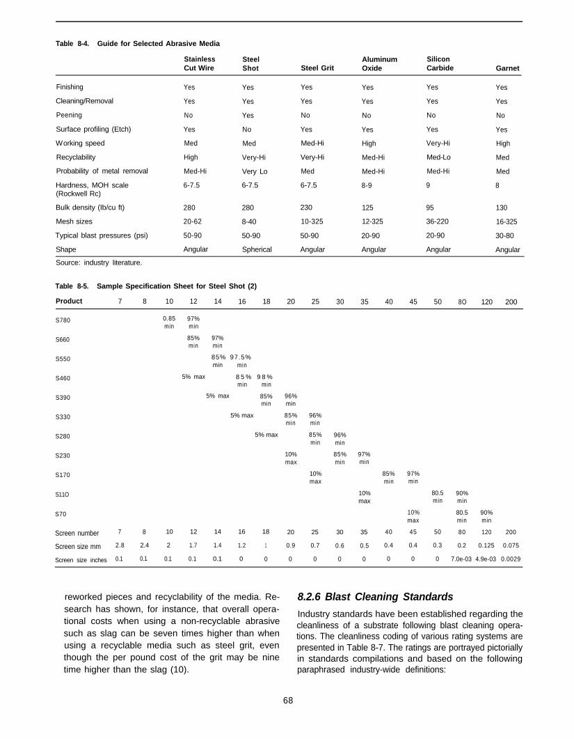
Table 8-4. Guide for Selected Abrasive Media
StainlessCut Wire
Finishing Yes
Cleaning/Removal Yes
Peening No
Surface profiling (Etch) Yes
Working speed Med
Recyclability High
Probability of metal removal Med-Hi
Hardness, MOH scale 6-7.5(Rockwell Rc)
Bulk density (Ib/cu ft) 280
Mesh sizes 20-62
Typical blast pressures (psi) 50-90
Shape Angular
Source: industry literature.
SteelShot
Yes
Yes
Yes
No
Med
Very-Hi
Very Lo
6-7.5
280
8-40
50-90
Spherical
Steel Grit
Yes
Yes
No
Yes
Med-Hi
Very-Hi
Med
6-7.5
230
10-325
50-90
Angular
Aluminum SiliconOxide Carbide
Yes Yes
Yes Yes
No No
Yes Yes
High Very-Hi
Med-Hi Med-Lo
Med-Hi Med-Hi
8-9 9
125 95
12-325 36-220
20-90 20-90
Angular Angular
Garnet
Yes
Yes
No
Yes
High
Med
Med
8
130
16-325
30-80
Angular
Table 8-5. Sample Specification Sheet for Steel Shot (2)
Product 7 8 10 12 14 16 18 20 25 30 35 40 45 50 8O 120 200
S780
S660
S550
S460
S390
S330
S280
S230
S170
S11O
S70
Screen number 7 8 10 12 14 16 18 20 25 30 35
Screen size mm 2.8 2.4 2 1.7 1.4 1.2 1 0.9 0.7 0.6 0.5
Screen size inches 0.1 0.1 0.1 0.1 0.1 0 0 0 0 0 0
0.85 97%min min
85% 97%min min
85% 97.5%min min
5% max 8 5 % 9 8 %min min
5% max 85%min
5% max
5% max
96%min
85% 96%min min
85%min
10%max
10%max
96%min
85% 97%min min
10%max
85% 97%min min
80.5 90%min min
10% 80.5 90%max min min
40 45 50 80 120 200
0.4 0.4 0.3 0.2 0.125 0.075
0 0 0 7.0e-03 4.9e-03 0.0029
reworked pieces and recyclability of the media. Re- 8.2.6 Blast Cleaning Standardssearch has shown, for instance, that overall opera-tional costs when using a non-recyclable abrasive
Industry standards have been established regarding the
such as slag can be seven times higher than whencleanliness of a substrate following blast cleaning opera-tions. The cleanliness coding of various rating systems are
using a recyclable media such as steel grit, even presented in Table 8-7. The ratings are portrayed pictoriallythough the per pound cost of the grit may be nine in standards compilations and based on the followingtime higher than the slag (10). paraphrased industry-wide definitions:
68

Table 8-6. Sample Specification Sheet for Steel Grit (2)
Product 7 6 10 12 14 16 18 20 25 30 35 40 45 50 80 120 200 325
G.12 0.8 0.9
G.14 80% 0.9
G.16 0 .75 0 .85
G.18 0.75 0.85
G.25 0.7 0.8
G.40 0.7 0.8
G.50 0 .65 0 .75
G.80 0 .65 0 .75
G.120 0.6 70%
Screen number 7 8 10 12 14 16 18 20 25 30 35 40 45 50 80 120 200 325
Screen size mm 2.80 2.4 2 1.7 1.4 1.2 1 0.9 0.7 0.6 0.5 0.4 0.4 0.3 0.2 0.1 0.075 0.045
Screen size inches 0.111 0.09 0.08 0.07 0.06 0.05 0.04 0.03 0.03 0.02 0.02 0.02 0.01 0.01 0.01 0.0049 0.0029
Table 8-7. Comparison of Designations for Blast Cleaning Finishes
Brush-Off Commercial Near-White Metal White Metal
Steel Structures Painting Council (USA) SSPC-SP7 SSPC-SP6 SSPC-SP10 SSPC-SP5
National Association of Corrosion Engineers (USA) NACE No. 4 NACE No. 3 NACE No. 2 NACE No. 1
Swedish Standards Organization SA-1 SA-2 SA-2½ SA-3
United Kingdom Standards (BS 4232) 3rd Quality 2nd Quality 1st Quality
l Brush-off: The cleaned surface, when viewed withoutmagnification, must be free of all visible oil, grease,and dirt as well as loose mill scale, rust, and pre-viously applied coatings. Adherent mill scale, rust,and old coatings may remain on the surface. Suchcontaminants are considered adherent if they cannotbe lifted with a dull putty knife.
l Commercial: The cleaned surface must be free of allvisible oil, grease, dirt, and dust as well as mill scale,rust, and previously applied coatings. Generally,evenly dispersed, very light shadows, streaks, anddiscolorations caused by stains of mill scale, rust, andold coatings may remain on no more than 33 percentof the surface. Also, slight residues of rust and oldcoatings may be left in the craters of pits if the originalsurface is pitted.
l Near-white metal: The cleaned surface must be freeof all visible oil, grease, dirt, and dust as well as millscale, rust, and previously applied coatings. Gener-ally, evenly dispersed, very light shadows, streaks,and discolorations caused by stains of mill scale, rust,and old coatings may remain on no more than 5percent of the surface.
l White metal: The cleaned surface must be free of allvisible oil, grease, dirt, and dust as well as mill scale,rust, and previously applied coatings. No traces ofcontaminants may remain on the surface.
Pictorial portrayals of abrasive cleaning standards arecompiled in the following trade association documents:
Steel Structures Painting Council Visual Standard(SSPC-VIS-1-89), Steel Structures Painting Council,Pittsburgh, PA.
NACE Visual Standard for Steel Surfaces AirblastCleaned With Sand Abrasive; NACE Standard TM-01-07, National Association of Corrosion Engineers,Houston, TX.
Swedish Standard (05/5900/67), Swedish StandardsOrganization (available from American Society forTesting Materials, Philadelphia, PA).
United Kingdom Standards (BS 4232).
The total cost of a standards compilation and a blastprofile comparator (see Section 8.2.3) is approximately$300.
8.3 Best Management Practices
The following management practices are recommendedfor enhancing abrasive blasting process efficiency:
l To maintain quality control, facility operators shouldperiodically inspect surfaces to ensure that industryblast cleaning standards are being met; also, theyshould occasionally measure the blast profile toguard against the potential for flash rusting.
69

To avoid flash rusting generally, line operators shouldapply a primer coating to clean surfaces within 8hours of abrasive blasting; in high-humidity environ-ments, a primer should be applied within 4 hours. Ifnear-term priming is not feasible, line operatorsshould wrap and/or store the cleaned workpiece un-der cover or apply a temporary corrosion preventive,even though this coating will need to be removedthrough degreasing before application of a topcoat(see Chapter 5).
To avoid the deposition of fingerprints and other inci-dental contaminants when processing white-metalworkpieces, operators should require workers to wearlatex gloves when handling the pieces after blastcleaning.
To ensure consistent control of the blast cleaningprocess, operators should thoroughly train relevantworkers, even though turnover tends to be high forsuch operations. Training materials (e.g., videos) areavailable from both the Steel Structures PaintingCouncil and the National Association of CorrosionEngineers.
To avoid contamination of the media feedstock, fac-cility operators should ensure that moisture is notcondensing on the hopper surfaces. Also, air supplylines should be equipped with oil and water traps.
To ensure optimum mixing of pressurized air and theabrasive media, operators should equip the blastingsystem with a hopper that has a concave head anda cone-shaped bottom to facilitate feed flow. Similarly,hose couplings should be flush with the inside of thehose and sized to minimize obstruction and leakageof pressure. Additionally, the mixing valve should beperiodically cleaned.
8.4 Process Variations (With CaseExamples)
8.4.1 Abrasive Blasting Preceded byDegreasing
Many paints and coatings operations subject work-pieces to abrasive blasting as well as degreasing in oneprocess line. In most cases, these two pretreatmentstages are used in conjunction to minimize contamina-tion of an abrasive that will be recycled in the blastingoperation. If a relatively expensive abrasive is beingused, such as steel shot, the facility operator will havea strong incentive to optimize its useful life. With aless-expensive media, such as sand, the operator willneed to weigh the tradeoff between the cost of replacingthe media more frequently and the water-use and waste-water-handling costs associated with degreasing (seeChapter 5).
If the facility operator chooses to recycle the blast mediawithout degreasing workpieces, the recycled abrasive islikely to entrain grease, metal fines, and other contami-nants and then deposit them on the surface of the nextuncoated piece. Coatings that are applied over suchcontaminants will have a high potential for prematurefailure, either gradually (by spalling) or catastrophically(by delaminating). Whereas the cost of taking steps toprevent such failures may be preclusive for some Iow-value end products sold in price-sensitive markets,achieving a reasonably durable coating is likely to be arequirement for many operations.
In most situations, the roughening of the metal substratethat can be achieved in abrasive blasting is particularlyimportant for enhancing adhesion. With marine coatingsystems, for example, the zinc-rich primers specified byindustry standards provide superior corrosion resistancebut have poor adhesion properties. Thus, the substrateprofile resulting from abrasive blasting enhances theability of the epoxy and polyurethane enamel coatingsapplied over the primer for marine workpieces to estab-lish a strong mechanical bond. The danger is that toohigh a blast profile would lead to premature corrosion ofthe substrate when subjected to marine environments.
Factors a facility operator should consider when decid-ing on whether to add a degreasing stage include:
l Regulations concerning VOC emissions and waste-water treatment.
l Equipment and floor-space requirements.
l Costs versus benefits in terms of the overall operation.
8.4.1.1 Case Example: Coating Failure Due toContamination of Recycled Media
A major fabricator of railcars installed an automatic sys-tem for blast cleaning steel plates upon delivery to thefacility. Immediately after blasting, a corrosion-resistantprimer was applied using an airless spray gun. Theprimed plates then were stored until required for fabri-cation. After assembly, a second coat of primer wasapplied, followed by a colored, decorative topcoat.
Occasionally, the operator discovered craters in thepaint film, requiring that certain areas of painted piecesbe reworked (i.e., scuff sanded followed by repainting).One day, however, the paint operator found that entiresides of several finished railcars had thousands of cra-ters on the surface. The coatings on these cars had to bestripped and then reblasted, reprimed, and refinished.
On close analysis of the process, it was found that theabrasive media was picking up so much oil and greaseover several months of recycling that the substrateswere being recontaminated. The problem was easilysolved by replacing the abrasive with new material. Toprevent such coating failures in the future, the company
70

added a pretreatment step for subjecting all steel platesto high-pressure, hot-water degreasing. In addition, kao-lin powder was added to the abrasive to absorb anytraces of oil or grease that might become entrained inthe media.
The most important change to the process was theaddition of aqueous degreasing. While this added toprocess costs, it prevented further failures and thusreduced the cost of labor and materials required torework rejected paint finishes. With the degreasing step,the company needed to handle the large quantities ofwastewater. This was accomplished, however, by direct-ing the spent water to a settling tank, then skimming offoil and grease and adjusting the pH before discharge.
The problem could have been avoided had the companyinitially used better management practices. Until thecatastrophic failures brought production to a halt, no oneat the company had fully assessed the unnecessarycosts and additional pollution generation incurred duringthe earlier months when sporadic failures had occurred.
8.4.2 Abrasive Blasting Followed byPhosphating
For some situations, subjecting workpieces to a phos-phating stage after abrasive blasting is recommended.Although few operations use both of these stages inconjunction, this approach can yield a superior mechani-cal bond between the substrate and the coating systemand thus improved corrosion resistance.
When workpieces are subjected to both abrasive blast-ing and phosphating, the operator should monitor theblast profile closely. Phosphate deposition can vary sig-nificantly depending on the profile of the substrateyielded by the blasting abrasive. A more pronouncedblast profile will result in a heavier phosphate coating.For example, deposition of an iron phosphate can varyfrom 30 to 220 mg/ft2 depending on the type of mediaused in blast cleaning.
8.4.2.1 Case Example: Coating Failure Due toPeening of the Substrate
A fabricator of steel cabinets intended to be used in alltypes of outdoor environments selected a powder coat-ing process for finishing the workpieces. Because ofmajor contamination on the substrate, the facility opera-tor abrasive blasted the workpiece surfaces before ap-plying an iron phosphate. The operator felt that thecombination of the blast profile plus the phosphate
deposition would benefit adhesion of the powder coatingand provide enhanced corrosion resistance.
During accelerated environmental tests of the cabinets,however, the powder coating failed catastrophically dueto poor adhesion. Extensive experimentation showedthat a heavy phosphate coating was required for thecabinets to pass the tests. Further experimentation indi-cated that the shape and hardness of the abrasiveselected were critical for accomplishing the appropriatephosphate deposition on the substrate; the steel sur-faces were being peened, and this hindered the phos-phate from adequately depositing on the surface. Aftera change to angular grit, which yielded a more activesurface, the phosphate coating weight increased ap-proximately threefold. With this pretreatment modifica-tion, the powder coating passed the accelerated testing.
The change of abrasive was accomplished within a fewdays and at little expense, and the problem of workpiecerejects was essentially eliminated.
8.5 References
1.
2.
3.
4.
5.
6.
7.
8.
9.
10.
Bennett, P.J. 1994. Abrasive air blast cleaning. In: Keane, J.D.,et al. (eds.), Steel Structures Painting Council, vol. 1, pp. 52-67.Third edition. Pittsburgh, PA.
Borch, E.A. 1994. Metallic abrasives. In: Keane, J.D., et al. (eds.),Steel Structures Painting Council, vol. 1, pp. 32-51. Third edition.Pittsburgh, PA.
Mallory, A.W. 1994. Mechanical surface preparation; CentrifugalBlast Cleaning. In: Keane, J.D., et al. (eds.), Steel StructuresPainting Council, vol. 1, pp.22-31. Third edition. Pittsburgh, PA.
Kerr, Ft. 1995. Personal communication between R. Joseph, ofRon Joseph 8 Associates, Saratoga, CA, and Robert Kerr, ofClemco Industries.
Hanna, MR. 1993. Versatile technique for surface preparation.Industrial Finishing 69(5):22 (May).
Hansel, D. In press. Industrial abrasive blasting systems. MetalFinishing Journal. (Scheduled for publication in 1996.)
Lampkin, W. 1995. Personal communication between R. Joseph,of Ron Joseph & Associates, Saratoga, CA, and Walter Lampkin,of Baghouse Services, Los Alamos, CA.
Murphy, M., and R. Joseph, eds. 1995. Metal Finishing OrganicGuide Book and Directory, vol. 93. No. 5A (May). New York, NY:Elsevier Science Publishers.
Robison, T.G., ed. 1994. Products Finishing 1994 Directory andTechnical Guide, vol. 58 (2A). Cincinnati, OH: Gardner Publica-tions.
Griese, II, J. 1988. Using recyclable steel grit for portable fieldapplications. J. Coatings and Linings (October), pp. 35-37.
71
Section 3Application Process Factors
73

Chapter 9Transfer Efficiency as It Affects Air, Water, and Hazardous Waste Pollution
9.1 Introduction
9.1.1 Pollution Prevention Considerations
Of all the strategies available to minimize pollution in apaints and coatings facility, improving transfer efficiencyis perhaps one of the most effective. Slight increases intransfer efficiency can result in significant pollution re-ductions as well as guaranteed cost reductions.
The concept of transfer efficiency is extremely simple: itis the ratio of the mass of solid coating deposited on asubstrate to the mass of solid coating used during theapplication. It can also be defined in terms of volume.The following equations express these definitions:
Transfer Efficiency =Mass solid coating deposited
Mass solid coating used
or
Transfer Efficiency =Volume solid coating deposited
Volume solid coating used
To illustrate the importance of this concept, suppose thata spray painter applies a coating to a metal filing cabinetusing a conventional air atomizing spray gun. The spraygun deposits much of the coating on the metal cabinet,but a significant amount of overspray is directed towardthe spray booth filter or drops to the spray booth floor.Clearly, the overspray is wasted and represents theinefficiency of the spray application. Wasted overspraycontributes to air, water, and hazardous waste pollution.It is evident, then, that making the process more efficientcan directly benefit pollution prevention.
The definition of transfer efficiency does omit a coupleof important related factors. First, transfer efficiency ac-counts for only the amount of solid coating (i.e., resins,pigments, extenders, and additives) that remains on thesteel cabinet after the solvents have evaporated, andrelates this to the total amount of solids that the spraygun applied. In both the numerator and denominator ofthe equation, therefore, the amount of solvent in thecoating is not relevant.
Secondly, the definition of transfer efficiency does notaccount for the dry film thickness of the substrate coat-
ing. The following, which builds on the previous exam-ple, illuminates this distinct weakness in the definition:
Suppose the spray painter who applied the previouscoating to the metal filing cabinet applies a coatingof 1 mil (1 mil = 0.001 inches) dry film thickness tothe substrate. If the spray painter deposits 80 per-cent of the solid content of the coating onto themetal surfaces and wastes 20 percent in the spraybooth, then transfer efficiency is 80 percent. Now,suppose that a second spray painter who is lessexperienced than the first applies the same coatingto an identical filing cabinet. If he deposits twice asmuch coating (i.e., 2 mil dry film thickness), but hetoo deposits 80 percent of the solids to the surfaces,transfer efficiency would also be 80 percent.
Thus, despite the fact that the second spray painteruses twice as much coating as did the first spraypainter, the transfer efficiency for both spray paint-ers is the same.
It is unfortunate that the definition does not encompassdry film thickness or the amount of solvent used. Thischapter, however, explores many strategies for improv-ing not only transfer efficiency, but overall efficiency ofthe coating application.
9.1.2 Decision-Making Criteria
Decision-making criteria relevant to transfer efficiency,as addressed in this chapter, are highlighted in Table 9-1.
9.2 Benefits of Improved TransferEfficiency
Benefits associated with improving transfer efficiencyinclude:
l Reduced air pollution (volatile organic compounds-VOCs).
l Reduced hazardous waste.
l Less frequent cleaning of guns, spray booths, and filters.
l Reduced use of chemicals in water-wash spray booths.
l Reduced discharge/treatment of water.
l Reduced costs.
74
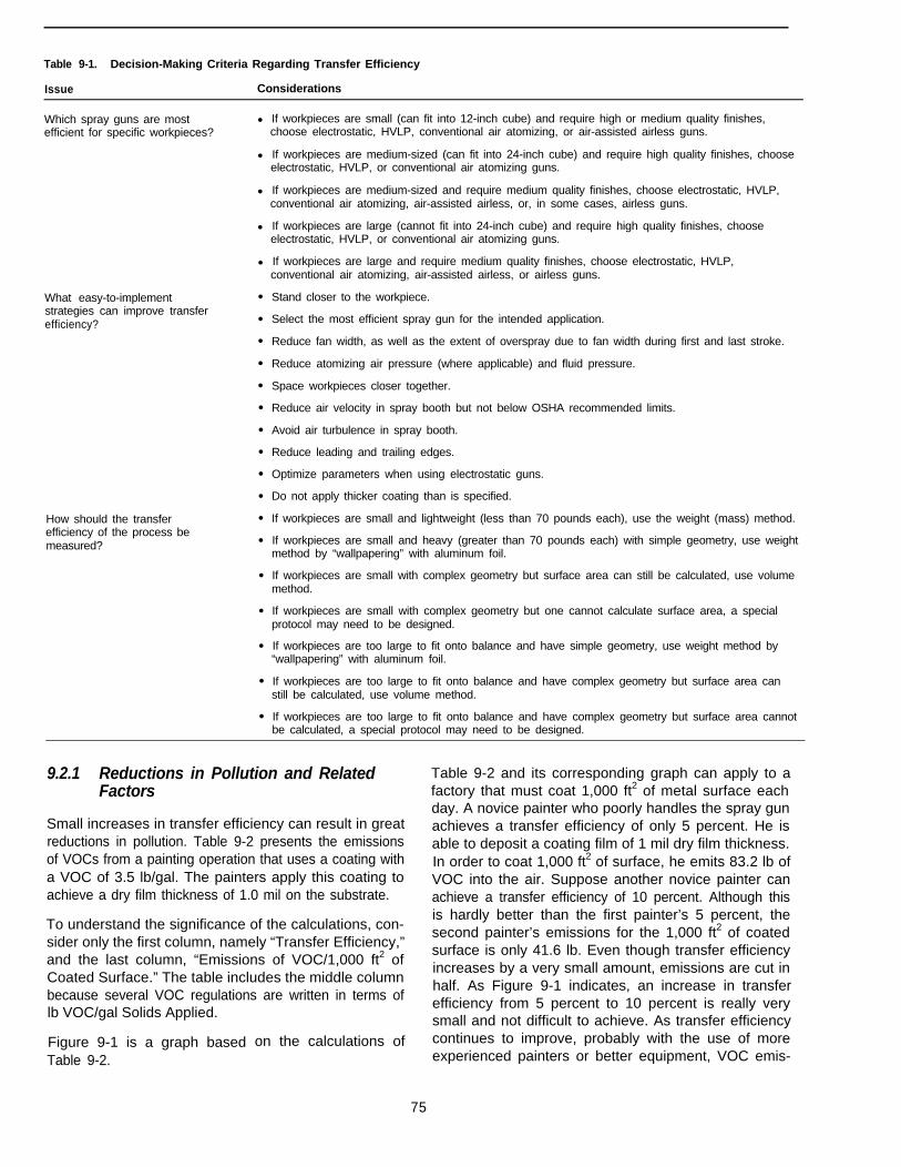
Table 9-1. Decision-Making Criteria Regarding Transfer Efficiency
Issue Considerations
Which spray guns are mostefficient for specific workpieces?
What easy-to-implementstrategies can improve transferefficiency?
How should the transferefficiency of the process bemeasured?
l If workpieces are small (can fit into 12-inch cube) and require high or medium quality finishes,choose electrostatic, HVLP, conventional air atomizing, or air-assisted airless guns.
l If workpieces are medium-sized (can fit into 24-inch cube) and require high quality finishes, chooseelectrostatic, HVLP, or conventional air atomizing guns.
l If workpieces are medium-sized and require medium quality finishes, choose electrostatic, HVLP,conventional air atomizing, air-assisted airless, or, in some cases, airless guns.
l If workpieces are large (cannot fit into 24-inch cube) and require high quality finishes, chooseelectrostatic, HVLP, or conventional air atomizing guns.
l If workpieces are large and require medium quality finishes, choose electrostatic, HVLP,conventional air atomizing, air-assisted airless, or airless guns.
l
l
l
l
l
l
l
l
l
l
l
l
l
l
l
l
l
Stand closer to the workpiece.
Select the most efficient spray gun for the intended application.
Reduce fan width, as well as the extent of overspray due to fan width during first and last stroke.
Reduce atomizing air pressure (where applicable) and fluid pressure.
Space workpieces closer together.
Reduce air velocity in spray booth but not below OSHA recommended limits.
Avoid air turbulence in spray booth.
Reduce leading and trailing edges.
Optimize parameters when using electrostatic guns.
Do not apply thicker coating than is specified.
If workpieces are small and lightweight (less than 70 pounds each), use the weight (mass) method.
If workpieces are small and heavy (greater than 70 pounds each) with simple geometry, use weightmethod by “wallpapering” with aluminum foil.
If workpieces are small with complex geometry but surface area can still be calculated, use volumemethod.
If workpieces are small with complex geometry but one cannot calculate surface area, a specialprotocol may need to be designed.
If workpieces are too large to fit onto balance and have simple geometry, use weight method by“wallpapering” with aluminum foil.
If workpieces are too large to fit onto balance and have complex geometry but surface area canstill be calculated, use volume method.
If workpieces are too large to fit onto balance and have complex geometry but surface area cannotbe calculated, a special protocol may need to be designed.
9.2.1 Reductions in Pollution and Related Table 9-2 and its corresponding graph can apply to aFactors factory that must coat 1,000 ft2 of metal surface each
day. A novice painter who poorly handles the spray gunSmall increases in transfer efficiency can result in great achieves a transfer efficiency of only 5 percent. He isreductions in pollution. Table 9-2 presents the emissions able to deposit a coating film of 1 mil dry film thickness.of VOCs from a painting operation that uses a coating with In order to coat 1,000 ft2 of surface, he emits 83.2 lb ofa VOC of 3.5 lb/gal. The painters apply this coating to VOC into the air. Suppose another novice painter canachieve a dry film thickness of 1.0 mil on the substrate. achieve a transfer efficiency of 10 percent. Although this
To understand the significance of the calculations, con-is hardly better than the first painter’s 5 percent, the
sider only the first column, namely “Transfer Efficiency,”second painter’s emissions for the 1,000 ft2 of coated
and the last column, “Emissions of VOC/1,000 ft2 ofsurface is only 41.6 lb. Even though transfer efficiency
Coated Surface.” The table includes the middle columnincreases by a very small amount, emissions are cut in
because several VOC regulations are written in terms ofhalf. As Figure 9-1 indicates, an increase in transferefficiency from 5 percent to 10 percent is really very
lb VOC/gal Solids Applied.
Figure 9-1 is a graph basedTable 9-2.
small and not difficult to achieve. As transfer efficiencyon the calculations of continues to improve, probably with the use of more
experienced painters or better equipment, VOC emis-
75

Table 9-2. Effect of Transfer Efficiency on VOC Emissions
Emissions ofEmissions of VOC VOC in lb
Transfer in lb VOC/gal VOC/1,000 ft2 ofEfficiency (%) Solids Applied Coated Surface
5 133.5 83.2
10 66.7 41.6
15 44.5 27.7
20 33.4 20.8
25 26.7 16.6
30 22.2 13.9
35 19.1 11.9
40 16.7 10.4
45 14.8 9.2
50 13.3 8.3
55 12.1 7.6
60 11.1 6.9
65 10.3 6.4
70 9.5 5.9
75 8.9 5.5
80 8.3 5.2
85 7.9 4.9
90 7.4 4.6
95 7.0 4.4
100 6.7 4.2
VOC of Coating 3.5 Ib\gal
Dry Film Thickness 1.0 mil
sions quickly drop to very small values (see Table 9-2and Figure 9-1).
Moreover, if one of the painters uses a paint brush toapply the coating and achieves a transfer efficiency of100 percent, yet can also apply the coating-at a uniformfilm thickness of 1 mil, his total VOC emissions for coat-ing the same surface area is only 4.2 lb. While the firstspray painter, whose transfer efficiency was 5 percent,emitted 83.2 lb of VOC into the air, the last painter whoused a paint brush, emitted only 4.2 lb to do exactly thesame job.
Of course, it is impractical to use a paint brush to applyall coatings. It is clear, however, that if using an efficientspray gun or other method of coating application canmaximize transfer efficiency, an enormous reduction inpollution will result.
While it may not be practical or cost-effective to achievetransfer efficiencies of 80 percent or more under mostcircumstances, spray painters can often achieve trans-fer efficiencies in excess of 50 percent. As Table 9-2notes, even a transfer efficiency of 50 percent causes
emissions to drop to only 8.3 lb of VOC/1,000 ft2 ofcoated surface.
While Table 9-2 and Figure 9-1 demonstrate only reduc-tions of emissions into the air, obviously as transferefficiency improves, the amount of overspray in thespray booth drops significantly. This translates into lessfrequent cleaning of the spray booth, as well as a reduc-tion in the disposal of used dry filters (in dry filter spraybooths) or of paint sludge (in water-wash spray booths).For water wash spray booths, improved transfer effi-ciency also reduces the use of chemicals needed todetoxify the paint sludge, and the discharge and treat-ment of water from the water trough.
9.2.2 Reduction in Costs
While increased transfer efficiency and reduced wastecontribute to preventing pollution, they also result inreduced costs. In order to fully appreciate the impacttransfer efficiency has on air, water, and waste pollution,as well as on costs, consider a spreadsheet that ac-counts for all factors. The tables in Appendix C servethis purpose.
The tables of this appendix present assumptions andcalculations based on a relatively small operation whichcoats 100 widgets per day. Table C-l of the appendixprovides a list of assumptions that are required to cal-culate cost savings due to improved transfer efficiency.Table C-2 provides the results of calculations that reflectthe total cost for waste, filters, labor, and wasted paintwhen the transfer efficiency is 30 percent. Table C-3 isidentical to Table C-2, except it lists the results when thetransfer efficiency is 45 percent. Table C-4 provides theformulas that are used to perform the calculations.
Using the spreadsheet structure and calculations modelpresented in this Appendix, the reader can estimatetransfer efficiency at his or her own facility. The readercan change any of the assumptions to see how effective,minor changes in the coating application which affecttransfer efficiency can provide dramatic benefits.
Table 9-3 of this chapter presents the total waste costsof this same relatively small operation which coats 100widgets per day. When the transfer efficiency of thisoperation is 30 percent, its annual waste costs are$102,750.62. If all of the assumptions remain the samebut transfer efficiency increases reasonably from 30 to45 percent, the operation can realize great savings (seeTable 9-3) namely $48,928.87.
It is entirely possible to realize this cost savings withoutspending a single dime on spray or other equipment.With training, painters can probably achieve this conser-vative increase in transfer efficiency. In addition, alongwith the cost savings, a 15 percent increase in transferefficiency contributes considerably to pollution prevention.
76
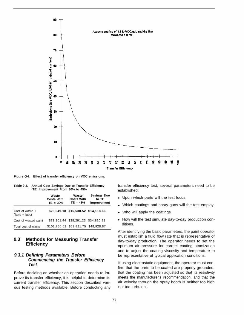
Figure Q-l. Effect of transfer efficiency on VOC emissions.
Table 9-3. Annual Cost Savings Due to Transfer Efficiency(TE) Improvement From 30% to 45%
Waste Waste Savings DueCosts With Costs With to TETE = 30% TE = 45% Improvement
Cost of waste + $29.649.18 $15,530.52 $14,118.66filters + labor
Cost of wasted paint $73,101.44 $38,291.23 $34,810.21
Total cost of waste $102,750.62 $53.821.75 $48,928.87
9.3 Methods for Measuring TransferEfficiency
9.3.1 Defining Parameters BeforeCommencing the Transfer EfficiencyTest
Before deciding on whether an operation needs to im-prove its transfer efficiency, it is helpful to determine itscurrent transfer efficiency. This section describes vari-ous testing methods available. Before conducting any
transfer efficiency test, several parameters need to beestablished:
l Upon which parts will the test focus.
l Which coatings and spray guns will the test employ.
l Who will apply the coatings.
l How will the test simulate day-to-day production con-ditions.
After identifying the basic parameters, the paint operatormust establish a fluid flow rate that is representative ofday-to-day production. The operator needs to set theoptimum air pressure for correct coating atomizationand to adjust the coating viscosity and temperature tobe representative of typical application conditions.
If using electrostatic equipment, the operator must con-firm that the parts to be coated are properly grounded,that the coating has been adjusted so that its resistivitymeets the manufacturer’s recommendation, and that theair velocity through the spray booth is neither too highnor too turbulent.
77
Another decision to make before starting a transfer effi-ciency test is whether to use the weight (mass) method(most common) or the volume method.
9.3.2 Using the Weight (Mass) Method
Determining transfer efficiency on a weight or massbasis, as is usually the case, requires purchasing orrenting an electronic balance capable of measuring towithin 0.5 g. (In this document, the words weight andmass are synonymous. While scientists use mass, mostothers prefer to use weight.) Available balances canweigh as much as 154 kg (70 Ibs) with this accuracy.The balance must sit on a hard surface such as a metaltable, concrete floor, or cement slab. Never place apiece of cardboard under the balance as it will lead toerroneous results.
In addition, the operator must shield the balance fromall drafts that may occur on a factory floor, perhaps bysurrounding the scale with large pieces of cardboard.The operator must also ensure that the pressure pot orcoating reservoir is not too heavy for the balance andthat the individual parts to be coated also fall within themaximum limit of the balance.
The balance should be set so that the air bubble in thebubble glass falls within the center of the glass. Inaddition, all four feet below the balance must be in firmcontact with the ground or surface. Finally, the operatormust calibrate the balance using standard weightswhich are often supplied by the balance manufactureror rental company.
The cost to conduct a transfer efficiency test can beminimal. Companies can usually rent electronic bal-ances for less than $300/week. A laboratory chargemight run approximately $150/sample. The only otherreal expense involves in-house labor. Of course, if acompany retains a consultant to conduct the test, costsmight range from $3,000 to $5,000, depending on thecomplexity of the operation.
9.3.2.1 Measuring the Weight of Coating DuringApplication
The paint operator should follow the steps below todetermine the weight (mass) of coating used during theapplication. This process begins by measuring the liquidcoating, then uses the information to calculate theweight (mass) of the solid coating.
1. Prior to commencing the transfer efficiency test, ap-propriately label each part to be coated and thenaccurately weigh each part on the electronic bal-ance. Record all of the weights.
2. Place the pressure pot or coating reservoir on thebalance and slowly fill with coating, ensuring not to
3.
4.
5.
At
exceed the limit of the balance even after tighteningthe pressure pot cover.
Before commencing the actual test, apply the coatingto several dummy parts to ensure that the coatingapplication is representative of day-to-day productionconditions.
To commence the test, disconnect the fluid and airhoses from the pressure pot. Do not allow any paintto drip to the floor as it is imperative that the coatingfills the line all the way up to the spray gun. Recordthe coating weight and then replace the air and fluidhoses and commence the spraying operation.
For accurate results, continue spraying until at least1 qt of the paint has been used (equivalent to ap-proximately 2.2 lb or 1 kg). After applying the coatingto the selected parts, immediately disconnect thefluid and air hoses from the pressure pot and recordthe second reading. Repeating this entire procedureat least three times can help in determining an aver-age transfer efficiency at the end of the trials.
any time during the test, take a small grab sample,approximately 1 pt of the coating, directly out of thepressure pot. Be sure to close the container to preventsolvent evaporation. Then send the sample to an ana-lytical laboratory which will conduct a percent weightsolids test in accordance with ASTM D2369. The ASTMD2369 is a standard test method for volatile coatings (1).
Do not bypass the sampling procedure by simply callingthe coating manufacturer to request information on thepercent weight solids or referring to the Material SafetyData Sheet (MSDS). Even a small discrepancy betweenthe manufacturer’s value and the actual value obtainedfrom the pressure pot sample will make a large differ-ence to the transfer efficiency calculations.
The weight (mass) of solids used is calculated by thefollowing equation:
Wt. (mass) Solids Used =
Wt. (mass) LiquidCoating* Percent Wt. Solids100
9.3.2.2 Determining the Weight or Mass of SolidCoating Deposited
As noted earlier, before starting the transfer efficiencytest, each part was labeled and weighed. After applyingthe coating, it must thoroughly cure before weighing thepart again. If the coating is normally air or force-dried,allow extra time for all of the solvent to evaporate.Curing the parts in an oven set at 230°F will result in amore accurate transfer efficiency reading, even if this isnot the normal method for curing. This oven curingschedule is identical to what the laboratory will use to
78
determine the percent weight solids of the one pintsample taken earlier during the test.
After the coating has thoroughly cured, weigh the parts.The difference between the weights of coated and un-coated parts represents the weight of solid coating de-posited. Knowing the weight (mass) of solid coatingused, and the weight or mass of solid coating deposited,calculate the transfer efficiency as follows:
Transfer Efficiency =Mass solid coating deposited
Mass solid coating used
9.3.2.3 Increasing Test Credibility
The credibility of the results depends entirely on theaccuracy of all the weighings. If the factory has drafts orif vibrations from the floor affect the balance, the opera-tor may wish to take two or three readings before record-ing any one weight. In addition, the laboratorydetermination of percent weight solids must be accu-rate. Finally, the accuracy of the results will increase ifcoating many parts during any one test, due to the largersample size.
9.3.3 Using the Volume Method
The volume method is not as accurate as the weightmethod. Facilities reserve this method for parts that aretoo large or heavy to accurately weigh. For example, afacility operator might use the volume method to meas-ure the transfer efficiency of a large transformer, streetsweeper, forklift, engine block (which is too heavy butnot too large for the balance).
When the object is large but has a relatively simpleshape, a facility operator can often still use the weightmethod by “wallpapering” the surface with preweighedaluminum foil. At the conclusion of the test, weighing thedried coating on the foil completes the calculations.
To measure transfer efficiency using the volume method,a laboratory must determine the percent volume solidsof the coating, as applied. To determine the volume ofsolid coating deposited, a lab measures the average filmthickness of the deposited coating, as well as the totalsurface area of the coated parts.
9.4 The Effects of Common Spray Gunson Transfer Efficiency
The most important equipment to affect transfer effi-ciency, and thus pollution prevention, in a paint andcoating facility is the spray gun. This section, therefore,describes available types of spray guns and discussestheir effects on transfer efficiency.
9.4.1 Conventional Air Atomizing Spray Guns
These guns are still the most popular for providing highquality finishes on a wide variety of substrates. Thespray guns work on the following principles.
The operator pumps fluid from a pressure pot to thespray gun under relatively low pressure, usually 10 to20 psi. Sometimes, a cup contains the coating which isthen siphoned directly to the gun.
The operator then feeds compressed air into the gunwhich mixes with the coating, finely atomizing it into verysmall particles. For most applications, the atomizing airpressure is 40 to 80 psi. One of the primary reasons forthe gun’s popularity is that the operator can adjust boththe atomizing air pressure and the fluid delivery ratebecause both controls are on the gun body itself.
Unfortunately, many operators set the atomizing airpressure considerably higher than what is necessary toproduce an acceptable finish. For instance, while an airpressure of 40 psi may be adequate to produce thedesired finish, the operator may choose to apply thecoating at the maximum shop or line pressure of 80 psior more. This, of course, can increase VOC emissions,waste, and clean-up efforts. Because of the high atomizingpressure, the finely divided spray particles form a fog inthe spray booth. Moreover, as the particles travel at arelatively high speed from the gun to the target, theopportunity for the particles to bounce off the surfaceand rebound into the spray booth increases. Conse-quently, the transfer efficiency for this type of spray gunis usually fairly low relative to the other types. For thisreason, the South Coast Air Quality Management Dis-trict (SCAQMD), among other jurisdictions, have highlylimited the conventional air atomizing gun. The actionsof SCAQMD are important because the industry looksto SCAQMD to assess future regulatory trends regard-ing transfer efficiency and spray guns.
A general perception exists that the transfer efficiencyfor this gun is always low, perhaps around 25 percent.This is absolutely not so. When operators use the con-ventional air atomizing spray gun at low air pressures(less than 40 psi), transfer efficiency can be consider-ably higher than 25 percent, and, depending on partsize, can even exceed 65 percent.
9.4.2 High Volume, Low Pressure AirAtomizing Spray Guns
The high volume, low pressure (HVLP) spray gun wasintroduced to the United States market in the mid-1980s.It is very similar to the conventional air atomizing gun.While the conventional gun atomizes the coating atpressures of 40 to 80 psi, HVLP guns use higher vol-umes of air at pressures less than 10 psi to perform thesame function. Many regulations, such as those writtenby the South Coast Air Quality Management District,
79
limit the air atomizing pressure to 10 psi to ensure therealization of transfer efficiency benefits from low airpressure.
Several methods are available for generating the highvolume, low pressure air. During the mid-1980s the mostcommon method was using a high speed turbine thatdraws large volumes of air directly from the surroundingspace. The turbine pushes this high volume of airthrough a large diameter hose to the spray gun, but theair pressure can range from as low as 0.5 to 10 psi. Thekey to atomizing the coating with this method is the highvolume of air that mixes with the coating inside the gun.In addition, the turbine tends to heat the air to a tem-perature of approximately 110oF, which appears tobenefit the application of the coating.
Historically, the turbine HVLP guns have been relativelyexpensive, with costs in the $2,000 to $15,000 range.More recently, spray gun vendors have introduced ver-sions that do not require a turbine to generate the highvolume air. Instead, they directly convert low volume,high pressure shop air, to high volume, low pressure bymeans of venturies or regulators. Typically, the incomingshop air is at 80 to 100 psi, while the air emerging fromthe cap of the spray gun is less than 10 psi. The volumeof air for this gun is considerably less than that emergingfrom the turbine gun.
The major advantage of these newer pressure conver-sion guns is that they can immediately replace conven-tional air atomizing spray guns without requiring anyother major capital purchases. The conversion units donot automatically heat the air as do the turbines, butseveral vendors provide in-line heaters with the optionof heating the air if desired. Currently, all types of HVLPguns are popular, even if regulations do not require theiruse, because they have been marketed as high effi-ciency guns. Operators can use these guns to applycoatings to small, medium, and large targets. Somereports claim that the guns cannot keep up with highproduction-line speeds, but facilities must determine thison a case-by-case basis.
Generally, HVLP guns have been successful in atomiz-ing a wide range of coatings, although some rheologiesdo not atomize well. Although the turbine-operatedHVLP guns are more expensive than the pressure-con-version HVLP guns, the turbine types are generally moreefficient at atomizing a wider range of coatings: there-fore, in some cases, they are the most cost-effectiveoption.
Transfer efficiency trials, which numerous companiesand agencies have conducted, have demonstrated thatthe HVLP guns are generally more efficient than othergun types, and in some instances even more efficientthan electrostatic spray guns. Each operating scenariodetermines how efficient one gun type will be relative to
the other types. One should not be misled by advertise-ments which claim that HVLP guns are always moreefficient than other gun types. Only on-line testing canprovide the answer.
9.4.3 Airless Spray Systems
The airless spray system works much like a home watersystem. When turning on the faucet at home to take ashower, high pressure from the city’s pumping stationforces water through small orifices in the shower head.Depending on the size of the orifices, the spray is eitherfine or coarse.
With an airless spray system, a hydraulic pump siphonsthe coating out of a reservoir such as a 55-gallon drum,and then pumps the coating, usually under pressures of1,000 to 3,000 psi, to the spray gun. The coating atom-izes as it passes through the small orifice (0.011 to 0.074inches) in the cap of the gun. The size and shape of theorifice determine the degree of atomization and theshape and width of the fan pattern. Moreover, a largeorifice permits a higher fluid flow rate than a small orifice.
Unlike the conventional air atomizing spray gun, theairless spray gun does not permit the operator the sameflexibility in setting spraying parameters. Further, becauseof the high fluid pressure, operators can apply largequantities of the coating relatively quickly. For this rea-son, operators often use the airless spray gun to applycoatings to large surfaces such as buildings, the sidesof vessels in petroleum refineries, structures such asbridges, etc. In addition, operators often use this gun incoating facilities where the coating application mustkeep up with fast moving conveyors.
EPA has traditionally associated this gun with transferefficiency values of approximately 40 percent but con-siderably higher values are obtainable. For instance,airless spray guns that coat large surfaces, such aslarge electrical control panels, railcars, ships, buildings,etc., are usually associated with much higher transferefficiency values. Alternately, operators usually do notuse this gun to coat small targets because the high fluidpressure tends to deflect small targets suspended onconveyor lines, and the generally high fluid deliveryrates make it difficult to achieve acceptable-looking fin-ishes. When using an airless spray gun to coat smalltargets, therefore, the operator can expect low transferefficiencies, sometimes even lower than those which aconventional spray gun could achieve.
This gun has not been approved by agencies such asSCAQMD.
9.4.4 Air-Assisted Airless Spray Guns
The principle of this spray gun is very similar to that ofthe airless gun in that high fluid pressures force thecoating through a small orifice in the spray gun cap.
80
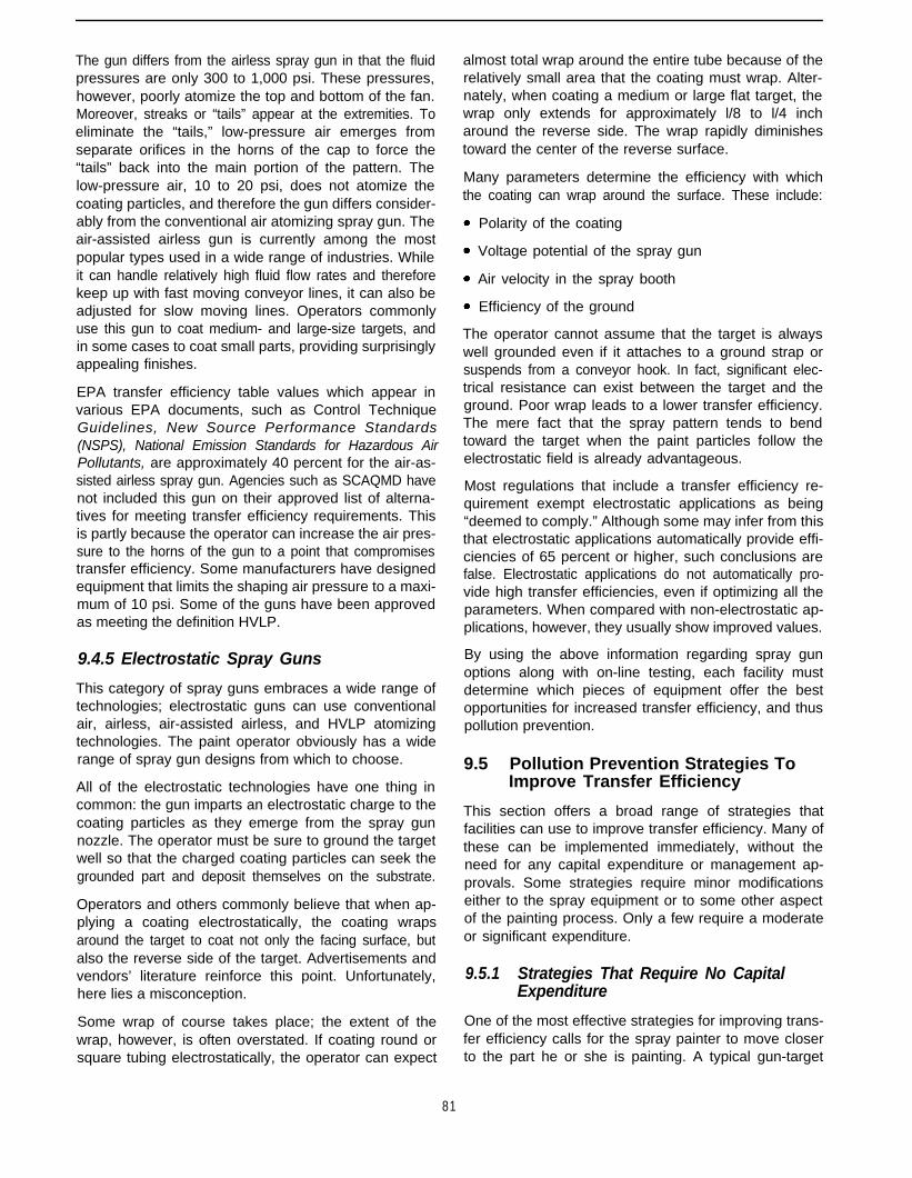
The gun differs from the airless spray gun in that the fluidpressures are only 300 to 1,000 psi. These pressures,however, poorly atomize the top and bottom of the fan.Moreover, streaks or “tails” appear at the extremities. Toeliminate the “tails,” low-pressure air emerges fromseparate orifices in the horns of the cap to force the“tails” back into the main portion of the pattern. Thelow-pressure air, 10 to 20 psi, does not atomize thecoating particles, and therefore the gun differs consider-ably from the conventional air atomizing spray gun. Theair-assisted airless gun is currently among the mostpopular types used in a wide range of industries. Whileit can handle relatively high fluid flow rates and thereforekeep up with fast moving conveyor lines, it can also beadjusted for slow moving lines. Operators commonlyuse this gun to coat medium- and large-size targets, andin some cases to coat small parts, providing surprisinglyappealing finishes.
EPA transfer efficiency table values which appear invarious EPA documents, such as Control TechniqueGuidelines, New Source Performance Standards(NSPS), National Emission Standards for Hazardous AirPollutants, are approximately 40 percent for the air-as-sisted airless spray gun. Agencies such as SCAQMD havenot included this gun on their approved list of alterna-tives for meeting transfer efficiency requirements. Thisis partly because the operator can increase the air pres-sure to the horns of the gun to a point that compromisestransfer efficiency. Some manufacturers have designedequipment that limits the shaping air pressure to a maxi-mum of 10 psi. Some of the guns have been approvedas meeting the definition HVLP.
9.4.5 Electrostatic Spray Guns
This category of spray guns embraces a wide range oftechnologies; electrostatic guns can use conventionalair, airless, air-assisted airless, and HVLP atomizingtechnologies. The paint operator obviously has a widerange of spray gun designs from which to choose.
All of the electrostatic technologies have one thing incommon: the gun imparts an electrostatic charge to thecoating particles as they emerge from the spray gunnozzle. The operator must be sure to ground the targetwell so that the charged coating particles can seek thegrounded part and deposit themselves on the substrate.
Operators and others commonly believe that when ap-plying a coating electrostatically, the coating wrapsaround the target to coat not only the facing surface, butalso the reverse side of the target. Advertisements andvendors’ literature reinforce this point. Unfortunately,here lies a misconception.
Some wrap of course takes place; the extent of thewrap, however, is often overstated. If coating round orsquare tubing electrostatically, the operator can expect
almost total wrap around the entire tube because of therelatively small area that the coating must wrap. Alter-nately, when coating a medium or large flat target, thewrap only extends for approximately l/8 to l/4 incharound the reverse side. The wrap rapidly diminishestoward the center of the reverse surface.
Many parameters determine the efficiency with whichthe coating can wrap around the surface. These include:
Polarity of the coating
Voltage potential of the spray gun
Air velocity in the spray booth
Efficiency of the ground
The operator cannot assume that the target is alwayswell grounded even if it attaches to a ground strap orsuspends from a conveyor hook. In fact, significant elec-trical resistance can exist between the target and theground. Poor wrap leads to a lower transfer efficiency.The mere fact that the spray pattern tends to bendtoward the target when the paint particles follow theelectrostatic field is already advantageous.
Most regulations that include a transfer efficiency re-quirement exempt electrostatic applications as being“deemed to comply.” Although some may infer from thisthat electrostatic applications automatically provide effi-ciencies of 65 percent or higher, such conclusions arefalse. Electrostatic applications do not automatically pro-vide high transfer efficiencies, even if optimizing all theparameters. When compared with non-electrostatic ap-plications, however, they usually show improved values.
By using the above information regarding spray gunoptions along with on-line testing, each facility mustdetermine which pieces of equipment offer the bestopportunities for increased transfer efficiency, and thuspollution prevention.
9.5 Pollution Prevention Strategies ToImprove Transfer Efficiency
This section offers a broad range of strategies thatfacilities can use to improve transfer efficiency. Many ofthese can be implemented immediately, without theneed for any capital expenditure or management ap-provals. Some strategies require minor modificationseither to the spray equipment or to some other aspectof the painting process. Only a few require a moderateor significant expenditure.
9.5.1 Strategies That Require No CapitalExpenditure
One of the most effective strategies for improving trans-fer efficiency calls for the spray painter to move closerto the part he or she is painting. A typical gun-target
81
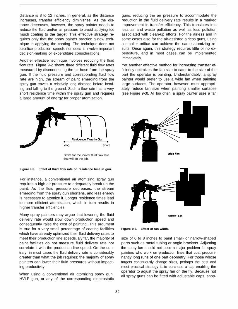
distance is 8 to 12 inches. In general, as the distanceincreases, transfer efficiency diminishes. As the dis-tance decreases, however, the spray painter needs toreduce the fluid and/or air pressure to avoid applying toomuch coating to the target. This effective strategy re-quires only that the spray painter practice a new tech-nique in applying the coating. The technique does notsacrifice production speeds nor does it involve importantdecision-making or expenditure considerations.
Another effective technique involves reducing the fluidflow rate. Figure 9-2 shows three different fluid flow ratesmeasured by disconnecting the air hose from the spraygun. If the fluid pressure and corresponding fluid flowrate are high, the stream of paint emerging from thespray gun travels a relatively long distance before bend-ing and falling to the ground. Such a flow rate has a veryshort residence time within the spray gun and requiresa large amount of energy for proper atomization.
guns, reducing the air pressure to accommodate thereduction in the fluid delivery rate results in a markedimprovement in transfer efficiency. This translates intoless air and waste pollution as well as less pollutionassociated with clean-up efforts. For the airless and insome cases also for the air-assisted airless guns, usinga smaller orifice can achieve the same atomizing re-sults. Once again, this strategy requires little or no ex-penditure, and in most cases can be implementedimmediately.
Yet another effective method for increasing transfer ef-ficiency optimizes the fan size to cater to the size of thepart the operator is painting. Understandably, a spraypainter would prefer to use a wide fan when paintinglarge surfaces. The operator, however, must appropri-ately reduce fan size when painting smaller surfaces(see Figure 9-3). All too often, a spray painter uses a fan
Short
Strive for the lowest fluid flow ratethat will do the job.
Figure 9-2. Effect of fluid flow rate on residence time in gun.
For instance, a conventional air atomizing spray gunrequires a high air pressure to adequately break up thepaint. As the fluid pressure decreases, the streamemerging from the spray gun shortens, and less energyis necessary to atomize it. Longer residence times leadto more efficient atomization, which in turn results inhigher transfer efficiencies.
Many spray painters may argue that lowering the fluiddelivery rate would slow down production speed andconsequently raise the cost of painting. This argumentis true for a very small percentage of coating facilitieswhich have already optimized their fluid delivery rates tomeet their production line speeds. By far, the majority ofpaint facilities do not measure fluid delivery rate norcorrelate it with the production line speed. On the con-trary, in most cases the fluid delivery rate is considerablygreater than what the job requires; the majority of spraypainters can lower their fluid pressures without impact-ing productivity.
When using a conventional air atomizing spray gun,HVLP gun, or any of the corresponding electrostatic
Narrow Fan
Figure 9-3. Effect of fan width.
size of 6 to 8 inches to paint small- or narrow-shapedparts such as metal tubing or angle brackets. Adjustingthe spray fan should not pose a major problem for spraypainters who work on production lines that coat predomi-nantly long runs of one part geometry. For those whosetargets continuously change sizes, perhaps the best andmost practical strategy is to purchase a cap enabling theoperator to adjust the spray fan on the fly. Because notall spray guns can be fitted with adjustable caps, shop-
82
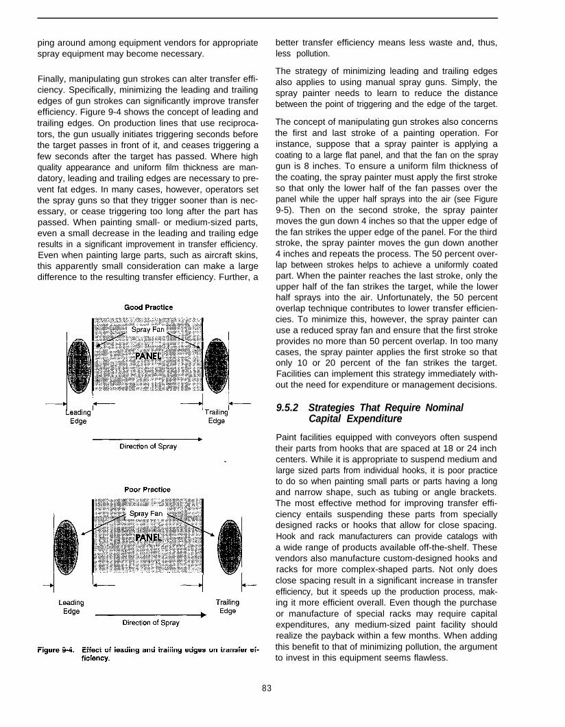
ping around among equipment vendors for appropriate better transfer efficiency means less waste and, thus,spray equipment may become necessary. less pollution.
Finally, manipulating gun strokes can alter transfer effi-ciency. Specifically, minimizing the leading and trailingedges of gun strokes can significantly improve transferefficiency. Figure 9-4 shows the concept of leading andtrailing edges. On production lines that use reciproca-tors, the gun usually initiates triggering seconds beforethe target passes in front of it, and ceases triggering afew seconds after the target has passed. Where highquality appearance and uniform film thickness are man-datory, leading and trailing edges are necessary to pre-vent fat edges. In many cases, however, operators setthe spray guns so that they trigger sooner than is nec-essary, or cease triggering too long after the part haspassed. When painting small- or medium-sized parts,even a small decrease in the leading and trailing edgeresults in a significant improvement in transfer efficiency.Even when painting large parts, such as aircraft skins,this apparently small consideration can make a largedifference to the resulting transfer efficiency. Further, a
The strategy of minimizing leading and trailing edgesalso applies to using manual spray guns. Simply, thespray painter needs to learn to reduce the distancebetween the point of triggering and the edge of the target.
The concept of manipulating gun strokes also concernsthe first and last stroke of a painting operation. Forinstance, suppose that a spray painter is applying acoating to a large flat panel, and that the fan on the spraygun is 8 inches. To ensure a uniform film thickness ofthe coating, the spray painter must apply the first strokeso that only the lower half of the fan passes over thepanel while the upper half sprays into the air (see Figure9-5). Then on the second stroke, the spray paintermoves the gun down 4 inches so that the upper edge ofthe fan strikes the upper edge of the panel. For the thirdstroke, the spray painter moves the gun down another4 inches and repeats the process. The 50 percent over-lap between strokes helps to achieve a uniformly coatedpart. When the painter reaches the last stroke, only theupper half of the fan strikes the target, while the lowerhalf sprays into the air. Unfortunately, the 50 percentoverlap technique contributes to lower transfer efficien-cies. To minimize this, however, the spray painter canuse a reduced spray fan and ensure that the first strokeprovides no more than 50 percent overlap. In too manycases, the spray painter applies the first stroke so thatonly 10 or 20 percent of the fan strikes the target.Facilities can implement this strategy immediately with-out the need for expenditure or management decisions.
9.5.2 Strategies That Require NominalCapital Expenditure
Paint facilities equipped with conveyors often suspendtheir parts from hooks that are spaced at 18 or 24 inchcenters. While it is appropriate to suspend medium andlarge sized parts from individual hooks, it is poor practiceto do so when painting small parts or parts having a longand narrow shape, such as tubing or angle brackets.The most effective method for improving transfer effi-ciency entails suspending these parts from speciallydesigned racks or hooks that allow for close spacing.Hook and rack manufacturers can provide catalogs witha wide range of products available off-the-shelf. Thesevendors also manufacture custom-designed hooks andracks for more complex-shaped parts. Not only doesclose spacing result in a significant increase in transferefficiency, but it speeds up the production process, mak-ing it more efficient overall. Even though the purchaseor manufacture of special racks may require capitalexpenditures, any medium-sized paint facility shouldrealize the payback within a few months. When addingthis benefit to that of minimizing pollution, the argumentto invest in this equipment seems flawless.
83

When operators paint small parts on pallets, the partsshould be spaced as closely together as possible tomaximize transfer efficiency.
Operators, however, cannot always achieve close spac-ing. For instance, painters can often not closely spacecomplex-shaped parts that require painting from variousangles without compromising finishing quality. Also,when using electrostatic spray guns, painters must pro-vide sufficient spacing to allow for some wrap to take place.
Another obvious strategy for improving transfer effi-ciency and minimizing pollution is to apply the coatingswith the most efficient spray guns applicable to thesituation. Section 9.4 already discussed the benefits andlimitations of most spray guns. Even though the pur-chase and installation of such equipment requires capi-tal, facilities usually realize cost paybacks within severalmonths.
A strategy often overlooked concerns the velocity of airpassing through a spray booth. OSHA requires a mini-mum air velocity of 100 to 120 feet per minute throughspray booths in which operators use manual spray guns.Alternately, OSHA allows facilities using automatedelectrostatic spray guns to lower their air velocities to 60feet per minute. Many paint facility operators inadver-tently run their booths at velocities well above theseguidelines values because they are unaware of thedeleterious effect this can have on transfer efficiency. Onthe other hand, some situations justify the higher veloci-ties. When spray applying large volumes of polyure-thanes or lead/chromate-containing paints, high airvelocities minimize potential health risks to the painters.A few facilities must quickly remove overspray from thebooth to prevent it from settling on freshly painted sur-faces; these cases also require high air velocities.
High air velocities, however, are expensive. They add toelectrical costs, and companies located in cold environ-ments must also consider additional heating costs. Mostfacilities should reduce air flow rates, but not far exceedOSHA requirements. If overspray at the lower flow ratesis high, painters should wear air-supplied respirators.Generally, painters who are accustomed to wearingsuch respirators enjoy them because of the clean andair-conditioned air that they supply. From the viewpointof transfer efficiency and pollution prevention, lower airvelocities through the spray booth allow the depositionof paint particles onto parts rather than into spray boothdry filters or water-wash curtains.
In situations requiring electrostatic spray guns, it is par-ticularly important to lower the air velocity yet avoidviolating any OSHA regulations. At high air velocities,the electrostatically charged paint particles do not havean opportunity to wrap the parts that they are intendedto coat. Instead, the strong flowing air current pulls theparticles into the booth.
Paint facilities that comprise several spray booths, allpulling from one air make-up system, may experienceviolently turbulent air velocities that change directionfrom one second to the next. In facilities such as these,it is not uncommon to see overspray blowing in theopposite direction from the spray booth filter bank orwater-wash curtain. Often, an unusual amount of over-spray deposited on spray booth ceilings and walls indi-cates turbulent air flow through the booth.
Because correcting turbulent air flow is often difficult,these cases may require air-conditioning or air-ventila-tion consultants to solve the problem. While this remedycosts money, the advantage to having a uniform, laminarair flow through a spray booth is improved transfer
84
efficiency and significantly reduced overspray and boothmaintenance. All these factors contribute to pollutionprevention.
9.5.3 Strategies That Require Moderate orSignificant Expenditure
Some paint facilities have such high VOC emissions thattheir state or local air pollution agencies require them toinstall abatement control equipment. The high cost ofsuch an installation often justifies looking for alternativestrategies to lower air emissions below the state’s regu-lated threshold. If the strategies this chapter has alreadycovered do not lower emissions sufficiently to precludethe use of abatement equipment, then a facility operatormay need to consider more drastic measures. Alternativeapplication methods such as dipping, flow coating, elec-trocoating, or powder coating, may resolve the emis-sions problems but the implementation of any of thesemethods requires many months of planning, testing,design, and of course implementation.
Despite the long lead time such a process change re-quires, and the costs associated with it, often this alter-native is ultimately more cost effective than installing anabatement control device.
Both choices result in the same goal-minimizingpollution.
9.6 References
1. American Society for Testing and Materials. 1995. In: Annual Bookof ASTM Standards: Paint Related Coatings and Aromatics, vol.6.01. ASTM. Philadelphia.
9.7 Additional Reading
Ewert, S.A. et al. 1993. Low cost transfer efficient paint spray equip-ment. Metal Finishing 91(8):59.
Hund, J.P. 1994. Spray application processes. Organic FinishingGuidebook and Directory. Metal Finishing 92(5A):114.
Joseph, Ft. 1993. Commentary on determining TE and VOC emis-sions. Metal Finishing 91(6):79.
Joseph, R. 1990. Spray application equipment for coatings and theirrelationship to transfer efficiency. Paper presented at the Westec‘90 (March).
Joseph, R. 1990. Transfer efficiency test protocol development andvalidation in custom a coating facility. Final Report, South CoastAir Quality Management District, CA (January).
Snowden-Swan, L., and P Worner. 1993. Determining TE and VOCemissions. Metal Finishing 91(6):73.
85
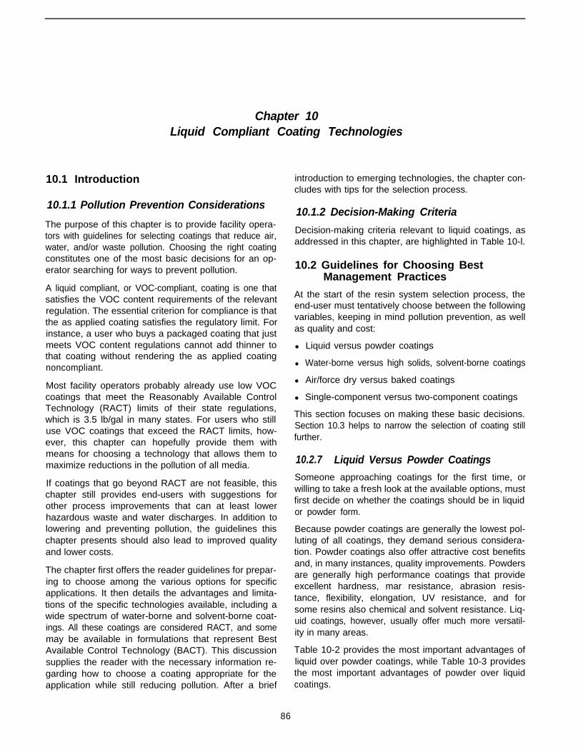
Chapter 10Liquid Compliant Coating Technologies
10.1 Introduction
10.1.1 Pollution Prevention Considerations
The purpose of this chapter is to provide facility opera-tors with guidelines for selecting coatings that reduce air,water, and/or waste pollution. Choosing the right coatingconstitutes one of the most basic decisions for an op-erator searching for ways to prevent pollution.
A liquid compliant, or VOC-compliant, coating is one thatsatisfies the VOC content requirements of the relevantregulation. The essential criterion for compliance is thatthe as applied coating satisfies the regulatory limit. Forinstance, a user who buys a packaged coating that justmeets VOC content regulations cannot add thinner tothat coating without rendering the as applied coatingnoncompliant.
Most facility operators probably already use low VOCcoatings that meet the Reasonably Available ControlTechnology (RACT) limits of their state regulations,which is 3.5 lb/gal in many states. For users who stilluse VOC coatings that exceed the RACT limits, how-ever, this chapter can hopefully provide them withmeans for choosing a technology that allows them tomaximize reductions in the pollution of all media.
If coatings that go beyond RACT are not feasible, thischapter still provides end-users with suggestions forother process improvements that can at least lowerhazardous waste and water discharges. In addition tolowering and preventing pollution, the guidelines thischapter presents should also lead to improved qualityand lower costs.
The chapter first offers the reader guidelines for prepar-ing to choose among the various options for specificapplications. It then details the advantages and limita-tions of the specific technologies available, including awide spectrum of water-borne and solvent-borne coat-ings. All these coatings are considered RACT, and somemay be available in formulations that represent BestAvailable Control Technology (BACT). This discussionsupplies the reader with the necessary information re-garding how to choose a coating appropriate for theapplication while still reducing pollution. After a brief
introduction to emerging technologies, the chapter con-cludes with tips for the selection process.
10.1.2 Decision-Making Criteria
Decision-making criteria relevant to liquid coatings, asaddressed in this chapter, are highlighted in Table 10-l.
10.2 Guidelines for Choosing BestManagement Practices
At the start of the resin system selection process, theend-user must tentatively choose between the followingvariables, keeping in mind pollution prevention, as wellas quality and cost:
l Liquid versus powder coatings
l Water-borne versus high solids, solvent-borne coatings
l Air/force dry versus baked coatings
l Single-component versus two-component coatings
This section focuses on making these basic decisions.Section 10.3 helps to narrow the selection of coating stillfurther.
10.2.7 Liquid Versus Powder Coatings
Someone approaching coatings for the first time, orwilling to take a fresh look at the available options, mustfirst decide on whether the coatings should be in liquidor powder form.
Because powder coatings are generally the lowest pol-luting of all coatings, they demand serious considera-tion. Powder coatings also offer attractive cost benefitsand, in many instances, quality improvements. Powdersare generally high performance coatings that provideexcellent hardness, mar resistance, abrasion resis-tance, flexibility, elongation, UV resistance, and forsome resins also chemical and solvent resistance. Liq-uid coatings, however, usually offer much more versatil-ity in many areas.
Table 10-2 provides the most important advantages ofliquid over powder coatings, while Table 10-3 providesthe most important advantages of powder over liquidcoatings.
86

Table 10-1. Decision-Making Criteria Regarding Liquid Compliant Coatings
Issue Considerations
Instead of using a liquid coating, would a powder coating be aviable option to coat workpieces in question?
Are the workpieces too large to fit into a baking oven?
Are the workpieces small enough to fit into an oven yet cannottolerate temperatures greater than 250oF?
l If powder coating appears inappropriate, use the remainingcriteria to decide on the best liquid coating for the job.
l If yes, you must consider an air/force dried coating.
l If yes, you must consider an air/force dried coating.
Are the workpieces small enough to fit into a baking oven and dothey require qualities such as hardness, abrasion and marresistance, and some chemical resistance?
l If yes, you may consider either baked coatings or air/force driedthermoset coatings such as epoxies and polyurethanes.
Are the workpieces too large to fit into an oven but requirehardness, abrasion and mar resistance, and some chemicalresistance?
l If yes, consider air/force dried thermoset single- ortwo-component coatings such as epoxies and polyurethanes.
Are the workpieces too large to fit into an oven, but do not require l If yes, consider a single component coating such as an alkyd orhardness, abrasion and mar resistance, and some chemical modified alkyd, which would be much less expensive than aresistance? two-component coating.
Is the location of the painting facility one in which operatorscommonly encounter low spray booth temperatures in the winter?
l If yes, solvent-borne coatings may be preferable to water-bornecoatings.
Is the painting facility located in an area that commonly has highrelative humidity (higher than 90%)?
l If yes, solvent-borne coatings may be preferable to water-bornecoatings.
Does the coating require excellent chemical and solventresistance, and also hardness, and abrasion and mar resistance?
l If yes, consider a solvent-borne epoxy primer followed by asingle or two-component polyurethane topcoat: new water-bornepolyurethanes might also be appropriate for wood products andmay soon be available for plastic and metal.
Does the workpiece that requires hardness, abrasion resistance,chemical and solvent resistance, and exterior durability also lenditself to a dipping application?
l If after referring to Chapter 11 of this text powder coating seemsappropriate, consider using this as an alternative to liquidcoating.
l If no, consider evaluating water-borne formulations.
l If yes, consider exploring autodeposited or electrodepositedcoatings.
Table 10-2. Advantages of Liquid Over Powder Coatings
Liquid Powder
Part Versatility More versatile for complex shaped parts. Often not suitable for parts with manyinaccessible areas and deep recesses.
Color Tinting
Application Versatility
Colors can be tinted if vendor delivers wrongshade. Easy to color- match.
Wide range of application equipment allowsflexibility in selecting appropriate equipment.This includes spray (many different types ofspray guns), dip, flow, and curtain.
Cannot be tinted on the job. If wrong shade, thepowder must be returned to vendor for blending.
Not suitable for applications which can easily bedipped or flow coated. Possibly can competewith curtain coatings, but often film build will betoo high.
May not be suitable for very large parts such asweldments, although some large parts, such aspipe lines, are being powder coated.
Line Speed Application equipment can keep up with veryfast-moving production line.
Tribo-charging guns can apply coatings at fasterline speeds than electrostatic guns, but for mostvery fast moving lines, liquid coatings may stillbe more cost-effective. This is especially true forcomplex shaped parts.
87
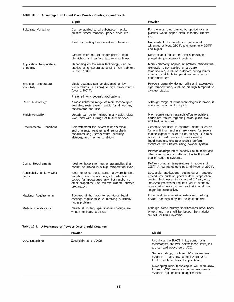
Table 10-2. Advantages of Liquid Over Powder Coatings (continued)
Liquid Powder
Substrate Versatility Can be applied to all substrates: metals,plastics, wood, masonry, paper, cloth, etc.
Ideal for coating heat-sensitive substrates.
Application TemperatureVersatility
End-use TemperatureVersatility
Resin Technology
Finish Versatility
Environmental Conditions
Curing Requirements
Applicability for Low CostItems
Masking Requirements
Military Specifications
Greater tolerance for “finger prints,” small Need cleaner substrates and sophisticatedblemishes, and surface texture cleanliness. phosphate pretreatment system.
Depending on the resin technology, can beapplied at temperatures ranging from sub-zeroto over 100oF
More commonly applied at ambient temperature.Generally is not applied at sub-zerotemperatures, such as outdoors during wintermonths, or at high temperatures such as onheat stacks, etc.
Liquid coatings can be designed for lowtemperatures (sub-zero) to high temperatures(over 1,500oF).
Preferred for cryogenic applications.
Almost unlimited range of resin technologiesavailable; resin system exists for almost anyconceivable end use.
Usually can be formulated in any color, glosslevel, and with a range of texture finishes.
Can withstand the severest of chemicalenvironments, weather and atmosphericconditions (e.g., temperature, humidity,altitude), and marine conditions.
Ideal for large machines or assemblies thatcannot be placed in a high temperature oven.
Ideal for fence posts, some hardware buildingsupplies, farm implements, etc., which arecoated for appearance only, but require noother properties. Can tolerate minimal surfacepreparation.
Because of the lower temperatures liquidcoatings require to cure, masking is usuallynot a problem.
Nearly all military specification coatings arewritten for liquid coatings.
Table 10-3. Advantages of Powder Over Liquid Coatings
Powder
For the most part, cannot be applied to mostplastics, wood, paper, cloth, masonry, rubber,etc.
Not available for substrates that cannotwithstand at least 250oF, and commonly 325°Fand higher.
Powders generally do not withstand excessivelyhigh temperatures, such as on high temperatureexhaust stacks.
Although range of resin technologies is broad, itis not as broad as for liquids.
May require more research effort to achieveequivalent results regarding color, gloss level,and texture finishes.
Generally not used in chemical plants, such asfor tank linings, and are rarely used for severemarine exposure, such as on oil rigs. Due to ascarcity in performance histories relative toliquid coatings, end-user should performextensive tests before using powder system.
Powder coatings more sensitive to humidity andother atmospheric conditions due to fluidizedbed of handling systems.
ReTire curing at temperatures in excess of325oF. A few resins cure at a minimum of 250oF.
Successful applications require certain processprocedures, such as good surface preparation,coating thicknesses in excess of 1.0 mil, etc.;improved processes required would probablyraise cost of low cost item so that it would nolonger be competitive.
If the workpiece requires extensive masking,powder coatings may not be cost-effective.
Although some military specifications have beenwritten, and more will be issued, the majorityare still for liquid systems.
Liquid
VOC Emissions Essentially zero VOCs Usually at the RACT limits; some resintechnologies are well below these limits, butare still well above zero VCC.
Some coatings, such as UV curables areavailable at very low (almost zero) VOClevels, but have limited applications.
Developing resin technologies will soon allowfor zero VOC emissions; some are alreadyavailable but for limited applications.
88
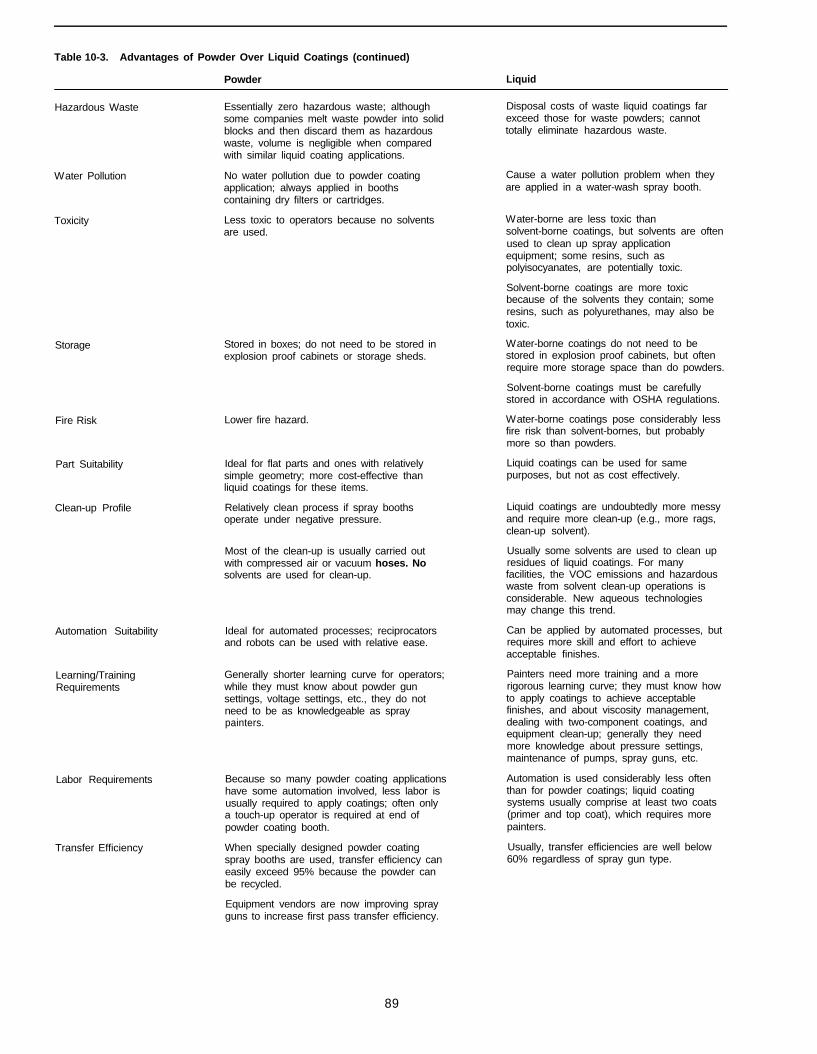
Table 10-3. Advantages of Powder Over Liquid Coatings (continued)
Powder Liquid
Hazardous Waste Essentially zero hazardous waste; althoughsome companies melt waste powder into solidblocks and then discard them as hazardouswaste, volume is negligible when comparedwith similar liquid coating applications.
Disposal costs of waste liquid coatings farexceed those for waste powders; cannottotally eliminate hazardous waste.
Water Pollution
Toxicity
Storage
Fire Risk
Part Suitability
Clean-up Profile
Automation Suitability
Learning/TrainingRequirements
Labor Requirements
Transfer Efficiency
No water pollution due to powder coatingapplication; always applied in boothscontaining dry filters or cartridges.
Cause a water pollution problem when theyare applied in a water-wash spray booth.
Less toxic to operators because no solventsare used.
Water-borne are less toxic thansolvent-borne coatings, but solvents are oftenused to clean up spray applicationequipment; some resins, such aspolyisocyanates, are potentially toxic.
Stored in boxes; do not need to be stored inexplosion proof cabinets or storage sheds.
Lower fire hazard.
Ideal for flat parts and ones with relativelysimple geometry; more cost-effective thanliquid coatings for these items.
Relatively clean process if spray boothsoperate under negative pressure.
Most of the clean-up is usually carried outwith compressed air or vacuum hoses. Nosolvents are used for clean-up.
Ideal for automated processes; reciprocatorsand robots can be used with relative ease.
Generally shorter learning curve for operators;while they must know about powder gunsettings, voltage settings, etc., they do notneed to be as knowledgeable as spraypainters.
Because so many powder coating applicationshave some automation involved, less labor isusually required to apply coatings; often onlya touch-up operator is required at end ofpowder coating booth.
When specially designed powder coatingspray booths are used, transfer efficiency caneasily exceed 95% because the powder canbe recycled.
Equipment vendors are now improving sprayguns to increase first pass transfer efficiency.
Solvent-borne coatings are more toxicbecause of the solvents they contain; someresins, such as polyurethanes, may also betoxic.
Water-borne coatings do not need to bestored in explosion proof cabinets, but oftenrequire more storage space than do powders.
Solvent-borne coatings must be carefullystored in accordance with OSHA regulations.
Water-borne coatings pose considerably lessfire risk than solvent-bornes, but probablymore so than powders.
Liquid coatings can be used for samepurposes, but not as cost effectively.
Liquid coatings are undoubtedly more messyand require more clean-up (e.g., more rags,clean-up solvent).
Usually some solvents are used to clean upresidues of liquid coatings. For manyfacilities, the VOC emissions and hazardouswaste from solvent clean-up operations isconsiderable. New aqueous technologiesmay change this trend.
Can be applied by automated processes, butrequires more skill and effort to achieveacceptable finishes.
Painters need more training and a morerigorous learning curve; they must know howto apply coatings to achieve acceptablefinishes, and about viscosity management,dealing with two-component coatings, andequipment clean-up; generally they needmore knowledge about pressure settings,maintenance of pumps, spray guns, etc.
Automation is used considerably less oftenthan for powder coatings; liquid coatingsystems usually comprise at least two coats(primer and top coat), which requires morepainters.
Usually, transfer efficiencies are well below60% regardless of spray gun type.
89

Table 10-3. Advantages of Powder Over Liquid Coatings (continued)
Powder Liquid
ElectrostaticApplications
Electrostatic powder applications are ideal forwire products because process transferefficiency remains above 95%.
Ideal for parts with cut ends and sharp edgesbecause one can often achieve higher filmbuilds in these areas.
Liquid coatings can rarely be applied asefficiently to wire products. Electrostatic liquidapplications are relatively inefficient. If theyare spray applied, transfer efficiencies areoften well below 20%. If they are dip applied,runs and drips often mar appearance ofcoated products.
Liquid coatings can be applied withelectrostatic spray equipment that helps tocover sharp ends and cut edges, but not aseffectively as powder coatings. Where goodcorrosion resistance in these areas ismandatory, powders are superior.
Coating Profile Requires just one coat application in mostcases. A single coat of powder performs thesame job as one coat of a liquid primerfollowed by a liquid top coat.
Rarely are liquid coatings applied as a singlecoat (usually only when color rather thancorrosion resistance is required).
A Naval Air specification calls for a singlecoat polyurethane, but this is applied overaluminum surfaces where corrosionresistance is better than for steel substrates.
Generally more uniform thicknesses can beachieved.
Film thickness variation tends to be muchgreater with liquid coatings.
For readers who think powder coating may be appropri-ate, Chapter 11 provides more details about the powdercoating process.
10.2.2 Water-Borne Versus Solvent-Borne
above 194°F are often regulated as “baked” coatingsand must follow lower VOC limits. Mostly, the limits forthe air/force dry category are higher than for the baked.For example, Table 10-7 lists the regulations guiding thecoatings used in the Miscellaneous Metal Parts industries.
Coatings
If powders do not constitute a feasible option, the nextstep should involve deciding between water-borne andsolvent-borne coatings. Because most states require atthe very least, RACT coatings, the discussion here onsolvent-borne coatings only considers VOC-compliant,high solids formulations. (High solids, a loosely usedterm, most commonly indicates a solvent-borne coatingwith a solids volume of 52 percent or more.).
10.2.4 Single-Component VersusPlural-Component
Tables 10-4 and 10-5 provide the most important advan-tages and limitations of each.
10.2.3 Air/Force Dry Versus Bake
Finally, another important basic factor to consider in-volves whether to select a single-component or plural-component technology. Generally, plural-componentcoatings have much better physical and chemical resis-tant properties. This superiority, however, does notcome without drawbacks. Single-component coatingsare much easier and less expensive to use. They alsoare usually associated with a better pollution preventionprofile. The most important differences between the twotechnologies are presented in Table 10-8.
Another important factor to consider is whether to pur-sue air/force dry coatings or select ones that bake atelevated temperatures, above 250oF. Baked coatingsusually have better physical and chemical-resistantproperties but they also have some limitations. Table10-6 provides some useful guidelines for each method.
10.2.4.1 Plural-Component Coatings
Regarding the resin technologies that this chapter dis-cusses, EPA and state regulations differentiate betweencoatings that air/force dry and ones that cure by baking.
Because the handling of plural-component coatings ismore complicated and because they are associated withmore hazardous waste than single-component coatings,plural-component coatings require a more detailed dis-cussion. Usually, a plural-component coating comprisestwo components. Occasionally, however, it comprisesthree components, one of which may be a thinner orchemical.
EPA defines air/force dried coatings as those that dry or The largest source of hazardous waste generated bycure below 194°F and many rules establish special VOC companies using plural-component coatings comeslimits for this category. In contrast, coatings that cure from batch mixing processes. While such mixing is
90
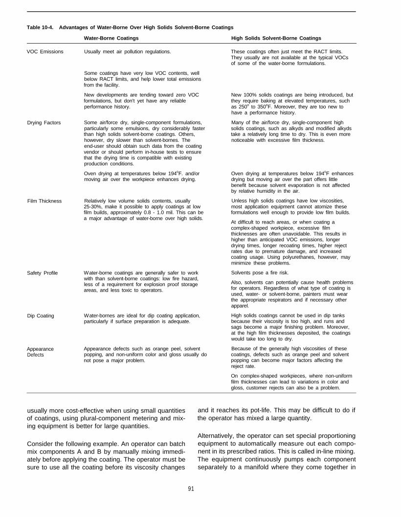
Table 10-4. Advantages of Water-Borne Over High Solids Solvent-Borne Coatings
Water-Borne Coatings High Solids Solvent-Borne Coatings
VOC Emissions Usually meet air pollution regulations. These coatings often just meet the RACT limits.They usually are not available at the typical VOCsof some of the water-borne formulations.
Some coatings have very low VOC contents, wellbelow RACT limits, and help lower total emissionsfrom the facility.
New developments are tending toward zero VOCformulations, but don’t yet have any reliableperformance history.
Drying Factors Some air/force dry, single-component formulations,particularly some emulsions, dry considerably fasterthan high solids solvent-borne coatings. Others,however, dry slower than solvent-bornes. Theend-user should obtain such data from the coatingvendor or should perform in-house tests to ensurethat the drying time is compatible with existingproduction conditions.
Oven drying at temperatures below 194oF. and/ormoving air over the workpiece enhances drying.
Film Thickness Relatively low volume solids contents, usually25-30%, make it possible to apply coatings at lowfilm builds, approximately 0.8 - 1.0 mil. This can bea major advantage of water-borne over high solids.
Safety Profile
Dip Coating
AppearanceDefects
Water-borne coatings are generally safer to workwith than solvent-borne coatings: low fire hazard,less of a requirement for explosion proof storageareas, and less toxic to operators.
Water-bornes are ideal for dip coating application,particularly if surface preparation is adequate.
Appearance defects such as orange peel, solventpopping, and non-uniform color and gloss usually donot pose a major problem.
New 100% solids coatings are being introduced, butthey require baking at elevated temperatures, suchas 250o to 350oF. Moreover, they are too new tohave a performance history.
Many of the air/force dry, single-component highsolids coatings, such as alkyds and modified alkydstake a relatively long time to dry. This is even morenoticeable with excessive film thickness.
Oven drying at temperatures below 194oF enhancesdrying but moving air over the part offers littlebenefit because solvent evaporation is not affectedby relative humidity in the air.
Unless high solids coatings have low viscosities,most application equipment cannot atomize theseformulations well enough to provide low film builds.
At difficult to reach areas, or when coating acomplex-shaped workpiece, excessive filmthicknesses are often unavoidable. This results inhigher than anticipated VOC emissions, longerdrying times, longer recoating times, higher rejectrates due to premature damage, and increasedcoating usage. Using polyurethanes, however, mayminimize these problems.
Solvents pose a fire risk.
Also, solvents can potentially cause health problemsfor operators. Regardless of what type of coating isused, water- or solvent-borne, painters must wearthe appropriate respirators and if necessary otherapparel.
High solids coatings cannot be used in dip tanksbecause their viscosity is too high, and runs andsags become a major finishing problem. Moreover,at the high film thicknesses deposited, the coatingswould take too long to dry.
Because of the generally high viscosities of thesecoatings, defects such as orange peel and solventpopping can become major factors affecting thereject rate.
On complex-shaped workpieces, where non-uniformfilm thicknesses can lead to variations in color andgloss, customer rejects can also be a problem.
usually more cost-effective when using small quantities and it reaches its pot-life. This may be difficult to do ifof coatings, using plural-component metering and mix- the operator has mixed a large quantity.ing equipment is better for large quantities.
Alternatively, the operator can set special proportioningConsider the following example. An operator can batch equipment to automatically measure out each compo-mix components A and B by manually mixing immedi- nent in its prescribed ratios. This is called in-line mixing.ately before applying the coating. The operator must be The equipment continuously pumps each componentsure to use all the coating before its viscosity changes separately to a manifold where they come together in
91
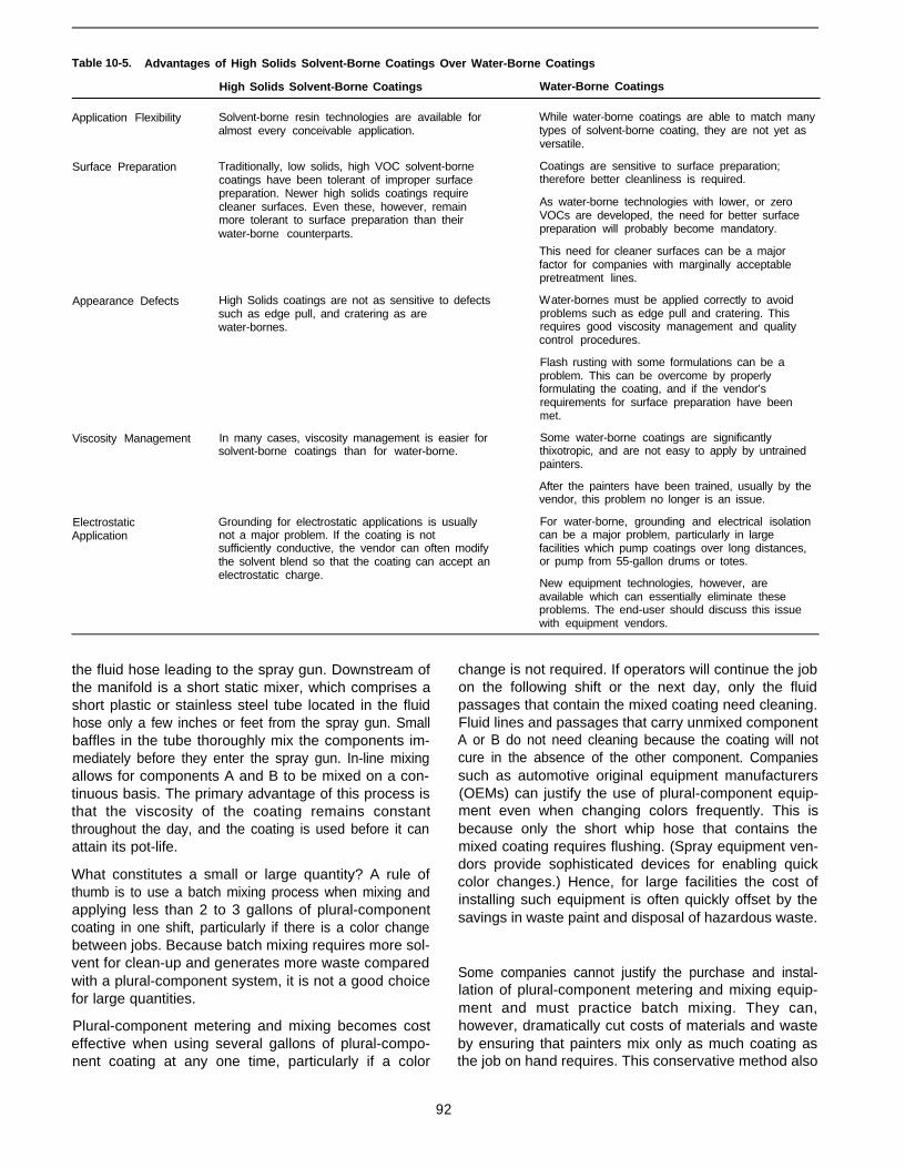
Table 10-5. Advantages of High Solids Solvent-Borne Coatings Over Water-Borne Coatings
High Solids Solvent-Borne Coatings Water-Borne Coatings
Application Flexibility Solvent-borne resin technologies are available foralmost every conceivable application.
Surface Preparation Traditionally, low solids, high VOC solvent-bornecoatings have been tolerant of improper surfacepreparation. Newer high solids coatings requirecleaner surfaces. Even these, however, remainmore tolerant to surface preparation than theirwater-borne counterparts.
Appearance Defects High Solids coatings are not as sensitive to defectssuch as edge pull, and cratering as arewater-bornes.
Viscosity Management In many cases, viscosity management is easier forsolvent-borne coatings than for water-borne.
ElectrostaticApplication
Grounding for electrostatic applications is usuallynot a major problem. If the coating is notsufficiently conductive, the vendor can often modifythe solvent blend so that the coating can accept anelectrostatic charge.
While water-borne coatings are able to match manytypes of solvent-borne coating, they are not yet asversatile.
Coatings are sensitive to surface preparation;therefore better cleanliness is required.
As water-borne technologies with lower, or zeroVOCs are developed, the need for better surfacepreparation will probably become mandatory.
This need for cleaner surfaces can be a majorfactor for companies with marginally acceptablepretreatment lines.
Water-bornes must be applied correctly to avoidproblems such as edge pull and cratering. Thisrequires good viscosity management and qualitycontrol procedures.
Flash rusting with some formulations can be aproblem. This can be overcome by properlyformulating the coating, and if the vendor’srequirements for surface preparation have beenmet.
Some water-borne coatings are significantlythixotropic, and are not easy to apply by untrainedpainters.
After the painters have been trained, usually by thevendor, this problem no longer is an issue.
For water-borne, grounding and electrical isolationcan be a major problem, particularly in largefacilities which pump coatings over long distances,or pump from 55-gallon drums or totes.
New equipment technologies, however, areavailable which can essentially eliminate theseproblems. The end-user should discuss this issuewith equipment vendors.
the fluid hose leading to the spray gun. Downstream ofthe manifold is a short static mixer, which comprises ashort plastic or stainless steel tube located in the fluidhose only a few inches or feet from the spray gun. Smallbaffles in the tube thoroughly mix the components im-mediately before they enter the spray gun. In-line mixingallows for components A and B to be mixed on a con-tinuous basis. The primary advantage of this process isthat the viscosity of the coating remains constantthroughout the day, and the coating is used before it canattain its pot-life.
What constitutes a small or large quantity? A rule ofthumb is to use a batch mixing process when mixing andapplying less than 2 to 3 gallons of plural-componentcoating in one shift, particularly if there is a color changebetween jobs. Because batch mixing requires more sol-vent for clean-up and generates more waste comparedwith a plural-component system, it is not a good choicefor large quantities.
Plural-component metering and mixing becomes costeffective when using several gallons of plural-compo-nent coating at any one time, particularly if a color
change is not required. If operators will continue the jobon the following shift or the next day, only the fluidpassages that contain the mixed coating need cleaning.Fluid lines and passages that carry unmixed componentA or B do not need cleaning because the coating will notcure in the absence of the other component. Companiessuch as automotive original equipment manufacturers(OEMs) can justify the use of plural-component equip-ment even when changing colors frequently. This isbecause only the short whip hose that contains themixed coating requires flushing. (Spray equipment ven-dors provide sophisticated devices for enabling quickcolor changes.) Hence, for large facilities the cost ofinstalling such equipment is often quickly offset by thesavings in waste paint and disposal of hazardous waste.
Some companies cannot justify the purchase and instal-lation of plural-component metering and mixing equip-ment and must practice batch mixing. They can,however, dramatically cut costs of materials and wasteby ensuring that painters mix only as much coating asthe job on hand requires. This conservative method also
92
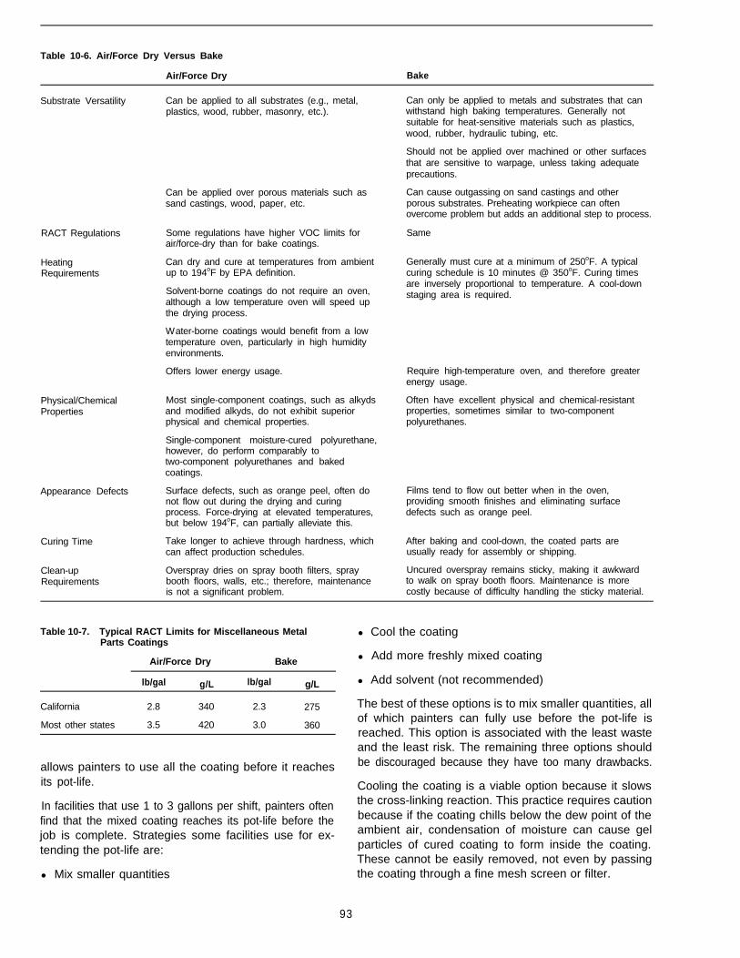
Table 10-6. Air/Force Dry Versus Bake
Air/Force Dry Bake
Substrate Versatility
RACT Regulations Some regulations have higher VOC limits forair/force-dry than for bake coatings.
Heating Can dry and cure at temperatures from ambientRequirements up to 194oF by EPA definition.
Solvent-borne coatings do not require an oven,although a low temperature oven will speed upthe drying process.
Water-borne coatings would benefit from a lowtemperature oven, particularly in high humidityenvironments.
Physical/ChemicalProperties
Appearance Defects
Curing Time
Clean-upRequirements
Can be applied to all substrates (e.g., metal,plastics, wood, rubber, masonry, etc.).
Can be applied over porous materials such assand castings, wood, paper, etc.
Offers lower energy usage.
Most single-component coatings, such as alkydsand modified alkyds, do not exhibit superiorphysical and chemical properties.
Single-component moisture-cured polyurethane,however, do perform comparably totwo-component polyurethanes and bakedcoatings.
Surface defects, such as orange peel, often donot flow out during the drying and curingprocess. Force-drying at elevated temperatures,but below 194oF, can partially alleviate this.
Take longer to achieve through hardness, whichcan affect production schedules.
Overspray dries on spray booth filters, spraybooth floors, walls, etc.; therefore, maintenanceis not a significant problem.
Can only be applied to metals and substrates that canwithstand high baking temperatures. Generally notsuitable for heat-sensitive materials such as plastics,wood, rubber, hydraulic tubing, etc.
Should not be applied over machined or other surfacesthat are sensitive to warpage, unless taking adequateprecautions.
Can cause outgassing on sand castings and otherporous substrates. Preheating workpiece can oftenovercome problem but adds an additional step to process.
Same
Generally must cure at a minimum of 250oF. A typicalcuring schedule is 10 minutes @ 350oF. Curing timesare inversely proportional to temperature. A cool-downstaging area is required.
Require high-temperature oven, and therefore greaterenergy usage.
Often have excellent physical and chemical-resistantproperties, sometimes similar to two-componentpolyurethanes.
Films tend to flow out better when in the oven,providing smooth finishes and eliminating surfacedefects such as orange peel.
After baking and cool-down, the coated parts areusually ready for assembly or shipping.
Uncured overspray remains sticky, making it awkwardto walk on spray booth floors. Maintenance is morecostly because of difficulty handling the sticky material.
Table 10-7. Typical RACT Limits for Miscellaneous MetalParts Coatings
Air/Force Dry Bake
lb/gal g/L lb/gal g/L
California 2.8 340 2.3 275
Most other states 3.5 420 3.0 360
allows painters to use all the coating before it reachesits pot-life.
In facilities that use 1 to 3 gallons per shift, painters oftenfind that the mixed coating reaches its pot-life before thejob is complete. Strategies some facilities use for ex-tending the pot-life are:
l Mix smaller quantities
l Cool the coating
l Add more freshly mixed coating
l Add solvent (not recommended)
The best of these options is to mix smaller quantities, allof which painters can fully use before the pot-life isreached. This option is associated with the least wasteand the least risk. The remaining three options shouldbe discouraged because they have too many drawbacks.
Cooling the coating is a viable option because it slowsthe cross-linking reaction. This practice requires cautionbecause if the coating chills below the dew point of theambient air, condensation of moisture can cause gelparticles of cured coating to form inside the coating.These cannot be easily removed, not even by passingthe coating through a fine mesh screen or filter.
93

Table 10-8. Single-Component Versus Plural-Component Coatings
Plural-Component CoatingsSingle-Component Coatings (Such as Alkyds) (Such as Polyurethanes)
Hazardous WasteConsiderations
Training Requirements
Mixing Requirements
Induction Times
Pot Life
Viscosity
Cleaning Considerations
Physical Properties
Chemical Properties
Cost Considerations
Generally result in considerably less hazardouswaste; whatever has been mixed and cannot beused, can be saved for another day.
Painters need not go through any specializedtraining program.
Require no special mixing instructions.
Require no induction times. The coatings can beapplied immediately.
There are no pot life considerations.
Because cross-linking does not take place untilthe coating has been applied, viscosity remainsconstant throughout the day (at constanttemperature).
Viscosity of the mixed coating increases withtime while the polymers cross-link.
Spray hoses do not need flushing out as If the coating has already been mixed, sprayfrequently. Large facilities that apply the same hoses must be flushed before the coating has ancoating each day infrequently clean the hoses. opportunity to gel.
Generally form softer and less abrasion-resistantfilms. This can lead to a higher reject rate due toearly damage. As the reject rate increases, so docosts and pollution.
Known for their superior physical properties.Many companies have invested intwo-component coatings specifically to reducereject rate.
Generally fewer chemical- and solvent-resistantproperties.
Known for their superior chemical-resistantproperties.
Generally, cost per gallon is considerably lessthan for two-component coatings. Costs can varyfrom a low of less than $10 per gallon to a highof $30 per gallon.
Usually more expensive than single-componentproducts. Costs can vary from a low of $25 pergallon to a high of well over $100 per gallon.Some exotic-colored automotive refinishingcolors can exceed $150 per gallon.
Maintenance costs are usually less becausecoatings do not harden as quickly in fluidpassages and are easier on pumps and sprayguns.
More hazardous waste is generated, particularlyif the two components are batch mixed.
Painters must be trained to properly mix andhandle two-component coatings.
Must be precisely mixed in the proportionsvendor recommends. Failure to do so can leadto improperly cured coatings, rejects, andgeneration of more unnecessary air, water, andwaste pollution.
May require induction time of up to 30 minutes(primarily for some epoxies).
Always have a limited pot life, and the mixedcoating must be used within that period.
Cost of replacement hoses, pumps, and sprayguns will increase because occasionally thecoating hardens before painters have had achance to clean fluid passages.
An operator must never add one component without thecorrect proportion of the other. Complete cross-linkingcan only occur when both components are present intheir stoichiometric proportions. Stoichiometric propor-tions imply that components A and B have the same totalnumber of functional groups. Paint chemists formulatecoatings to allow for simple mixing ratios, such as 1:1,2:1, 4:1, etc. For instance, if only component A is addedto extend the pot-life, the cured coating may tend toremain soft and cheesy, and will lose much of its chemi-cal- and solvent-resistant properties. On the other hand,if adding only component B, the cured coating may betoo hard and brittle, and will tend to crack and spall fromthe surface.
Finally, facilities should strongly condemn adding sol-vent to extend pot-life, even though it is a popularmethod. Adding solvent carries with it a great possibilitythat the VOC content of the mixture will exceed theregulated limit, exposing the company to a possible
Notice of Violation. Worse than this, however, the sol-vent is added to a coating that has already started topolymerize. While the painter may be satisfied with thefinish of the applied coating, the coating may harden andcure before all of the solvent has had an opportunity toevaporate out of the film. The entrapped solvent mightgradually migrate to the coating/substrate interface,loosening the adhesive bond between the primer andthe substrate. Catastrophic coating delamination canoccur, which may only become evident months or per-haps years after the finished product has been in service.
10.3 Water-Borne Coatings
10.3.1 Overview
The term “water-borne” describes coatings in which thepredominant solvent is water. Organic solvents (VOCs)are also used but, for the most part, their concentration
94

is small. In many formulations the ratio between theamount of water and organic solvent is 80:20.
The organic solvents, often referred to as co-solvents,enhance the formation of the coating film, especiallyduring the drying process when the water is evaporatingfrom the deposited coating. As resin manufacturers de-velop new resin technologies, they are reducing theamount of co-solvent required to form the film. Currently,new formulations exist that contain no co-solvents, andconsequently have zero VOC. Although this chapter willcover these, they do not yet have a long-term perform-ance history; therefore, most end-users will probablyconsider the more conventional water-borne coatings.
The term “water-borne” includes water-reducibles,emulsions (latexes), and dispersions. Most vendor datasheets do not make any distinction between the threetypes. Because the end-user does not need to know thedifferences between these types in order to select anappropriate coating, this chapter does not cover thedistinctions.
Most VOC regulations limit the VOC content of a coatingin terms of pounds per gallon or grams per liter, lesswater and less exempt solvent. Because exempt sol-vents, such as methylene chloride and l,l,l trichlo-roethane are being phased out, this chapter does notaddress resin technologies that rely on these solventsfor compliance.
When dealing with water-borne coatings, the end-usermust thoroughly understand the terminology most regu-lations use. For instance, 1.0 gallon of a water-bornecoating contains many ingredients: the resin (or binder),pigments, extender pigments, coalescing agents, asmall quantity of co-solvents, and usually a fairly sub-stantial amount of water. The volatile portion of thecoating comprises the co-solvents and water. In a galloncan, the co-solvents, which are considered to be theVOCs, may account for less than 1.0 pound.- In otherwords, the VOC content of the coating may only be 1.0pound/gallon. The VOC regulations, however, requirethat the VOC content of the coating be calculated as ifno water were in the coating. Depending on the coatingformulation, the VOC content, less water, may be con-siderably higher, such as 2.0 pounds/gallon or more.
Figure 10-l a illustrates what 1.0 gallon of water-bornecoating might look like if separating the ingredients intodiscrete layers. Clearly, the amount of VOC in the canwould be very small, especially when compared with theamount of water. If water were removed from the can sothat the coating only comprised the VOC and solidsportions, and if the can were then filled to the gallonmark, the contents would resemble Figure 10-1 b. WhenEPA and state regulations specify a VOC content lesswater, they refer to the VOC content represented inFigure lo-lb.
(a) (b)
Including water Excluding water
Figure 10-1. VOCs in water-borne coatings.
In order to understand the rationale for this approach,remember that in applying a coating, one is interestedonly in the amount of solid that a substrate needs de-posited. For instance, when applying a red enamel overa yellow primer, a painter uses only as much coating aswill completely hide the underlying color. For many coat-ings, a dry film thickness of 1 mil (0.001 inch) maysuffice. It does not matter if the coating is water-borneor solvent-borne; the only consideration is depositingthe specified dry film thickness of solid coating. Assum-ing that the composition of the solid ingredients is thesame in both coatings of Figure 10-1, a painter woulddeposit exactly the same amount of solid coating in eachcase. The only difference between the two figures is thelack of water from the second figure. Because the galloncan in Figure 10-1a has less solids than that in Figurelo-lb, a painter would use a greater volume of theFigure 10-1 a coating to deposit the same amount of solidcoating as he would to apply the coating in Figure lo-lb.
Note that the ratio of VOC to solid in Figure 10-1a is thesame as the ratio of VOC to solid in Figure 10-lb. Insummary, regardless of which paint can (Figure 10-1aorb) a painter uses to coat a substrate, the same volumeof solids will be applied, thus emitting the same amountof VOCs to do the job.
10.3.2 Water-Borne Air/Force Dry Alkyds,Acrylics, Acrylic-Epoxy Hybrids
Probably the most common water-borne coatings formetals, air- or force-dry at temperatures below 194°F. Awide range of coating formulations fall into this broadcategory. The most commonly available technologies
95
are water-borne alkyds and modified alkyds, acrylic la-texes, and acrylic epoxy hybrids. Often, consumers areunaware of which of these technologies they are pur-chasing because manufacturers frequently sell the coat-ings as generic water-borne products. A brief descriptionof the basic differences follows.
Water-reducible, or water-thinnable, alkyds and modi-fied alkyds are similar to the solvent-borne alkyds withwhich most companies are familiar. Like the solvent-borne coatings, they are modified polyesters but havehigh acid values and employ special chemical blockingagents such as carboxylic acid functionalities. When thealkyds are neutralized with ammonia or volatile amines,it is possible to use water as the reducing liquid. Al-though they may take longer to dry, the resulting coat-ings have gloss, flow, and leveling properties similar totheir solvent-borne counterparts.
The acrylic latexes include other polymers such as vinylacrylic and styrene acrylic. The resins are high molecu-lar weight polymers dispersed as discrete particles inwater. Those formed by polymerizing a single monomerare called homopolymers, while those polymerized froma blend of two or more different monomers are calledcopolymers. Most of the latexes used to coat miscella-neous metal parts and architectural substrates are co-polymers.
Latex coatings do not undergo a chemical change asthey dry. The basic latex polymer and specific modifica-tions are responsible for the characteristics of hardness,flexibility, chemical resistance, abrasion resistance, andphysical and chemical attributes. Acrylic latexes areknown for their good exterior durability and excellentresistance to ultraviolet (UV) degradation. In outdoorexposure, they retain their original gloss and color overlong periods. In this regard, they are superior to unmodi-fied alkyds, which tend have poorer gloss and colorretention.
Manufacturers specify acrylic epoxy hybrids even lesscommonly than the other water-borne products. Thesehybrids comprise two- or three-package systems inwhich emulsified epoxies cross-link with aqueous acryl-ics. Properly formulated coatings are corrosion resistantand can produce finishes that have very good gloss,hardness, alkali, and abrasion resistance. Unlike con-ventional solvent-based epoxies, some mixed water-borne coatings have pot-lives of up to 36 hours atreasonable ambient temperatures. End-users preferacrylic epoxy hybrids for applications that require hard-ness, flexibility, and chemical resistance.
10.3.2.1 Advantages
As a generic group, water-reducible formulations, dis-persions, and emulsions are ideal for companies thatstill need to comply with VOC regulations yet do not
require their coatings have sophisticated properties. Asa group, the water-bornes tend to have VOC contentswell below 2.0 lb/gal (240 g/L), less water, and some areeven below 1.5 lb/gal (180 g/L). Actual VOCs includingwater are usually below 1.25 lb/gal (150 g/L), and thismakes them an ideal choice for companies that have aneed to dramatically reduce their VOC emissions.
Generally, they exhibit good performance properties, butare probably not as durable or chemical- and solvent-re-sistant as two-component polyurethanes, epoxies, orbaked finishes. Facilities would consider them for appli-cations such as dipping primers and topcoats, generalpurpose shop primers, and spray applied enamels. Theyare suitable for coating steel, aluminum, galvanizing,plastic, wood, and architectural substrates. In addition,they are available in a wide range of colors and glosslevels.
Typical end-uses include steel roof trusses, steel build-ing support structures, farm implements (not combinesor tractors), electrical cabinets, boxes, frames, fenceposts, and similar general metal products. The electron-ics and business machines industries currently usethem to coat plastic computer housings, keyboards, andsimilar items. The architectural industry uses these coat-ings for interior and exterior walls, ceilings, concretebridge structures, and other commonly used masonrysurfaces. In the industrial maintenance industry, water-bornes can be used to coat items such as steel struc-tures and hand rails provided that there is no exposureto chemical and solvent fumes or liquids. The coatingsformulated for architectural end-use differ from thoseformulated for industrial use. The latter are designed toprovide metal parts with corrosion resistance.
These water-borne coatings have a host of other advan-tages associated with their actual application. They canbe spray-applied with standard equipment. In addition,they can be touched-up with self (i.e., with the very samecoating). And like their solvent-borne counterparts, theyare available in a wide range of texture finishes.
Water-borne coatings also have safety and pollution-prevention advantages. Because of their high watercontent they pose a low fire hazard. Moreover, theygenerally have lower toxicity because of the reducedconcentration of organic solvents.
Unlike solvent-borne coatings, operators can flushwater-bornes from spray hoses with tap water. Theusual procedure for cleaning the hoses is to flush withwater, follow with solvent, and follow again with water.The small amount of solvent is necessary to clean outdried or non-water-soluble coating residues from theinside surfaces of the fluid hose.
96

10.3.2.2 Limitations
Most of the limitations associated with these water-borne coatings relate to their performance. Comparedwith 2-part polyurethanes or baking water-reducibles,they have poorer exterior durability and poorer resis-tance to salt spray, humidity, chemicals, and solvents.
In general, the coatings do not meet standards for highperformance in industries such as heavy-duty mainte-nance, aerospace, appliance, and automotive. In addi-tion, many formulations require a greater learning curvewith regard to viscosity management compared withother compliant coatings.
When applying the coatings in humid or cold environ-ments, it is important for operators to force-dry them ata low oven temperature of approximately 120o to 150°F.If no oven is available, consider blowing air over theparts to promote the evaporation of water from the coat-ing film. Omitting this step can lead to a poor quality film,initially resulting in handling damage and possibly theearly onset of corrosion and other premature failures.
Although the lower concentrations of solvents in theirformulations benefit pollution prevention, this alsocauses these coatings to be more sensitive to substratecleanliness than most solvent-borne coatings. Similarly,the clean-up process these coatings require also re-duces pollution, as described earlier. Unlike solvent-borne coatings, however, operators must factor in a three-step process: water, solvent, water.
10.3.3 Water-Borne Epoxy Water-ReducibleAir/Force Dried Coatings
Manufacturers supply these coatings as two- or three-package systems. The most commonly available water-reducible epoxies are formulated as primers complyingwith military specifications MIL-P-53030 (lead- and chro-mate-free) and MIL-P-85582 (containing chromates).Facilities can topcoat them with most other coating sys-tems, such as polyurethanes, particularly when requir-ing good corrosion resistance. Companies that do notneed to comply with military specifications can alsoconsider using these coatings because they are com-patible with nonspecification topcoats. As with all high
97
Water-borne epoxy water-reducible air/force dried coat-ings have been available since the early 1980s and havea proven history of performance. These high perform-ance coatings most often are used as air/force dry coat-ings, where they can be cured at room temperature, orbelow 194°F. Although many data sheets show they areavailable at 2.8 lb/gal (340 g/L), less water, newer for-mulations are approximately 10 percent lower. Theyprovide a viable choice for companies wanting to signifi-cantly lower their VOC emissions without compromisingperformance.
performance coatings, properly prepared surfaces aremandatory.
Because epoxies tend to chalk when exposed toweather and sunlight, they usually do not serve as out-door topcoats. For interior exposure, however, such asthe internal linings of steel pipes and vessels, pumps,and laboratory equipment, they can serve as both prim-ers and topcoats. As primers, they are commonly speci-fied for steel weldments, such as automotive chassis,cabs, truck bodies, military hardware, steel and alumi-num frames, cold rolled steel panels and cabinets, aero-space components, and electronic components.
An end-user should not implement this technology untilafter performing extensive on-line testing to ensure thatthe product is compatible with production and perform-ance requirements.
10.3.3.1 Advantages
The first advantage to note regarding these coatingsrelates to pollution prevention. The VOC is below theRACT limit for all states, including California. This groupof coatings serves as an ideal choice for a high perform-ance primer when emission reductions are important.The VOC content is below 2.8 lb/gal (340 g/L), lesswater, for the mixed product, and is approximately 1.5lb/gal (180 g/L), including water.
These coatings also offer a range of choices. Primersare available in both chromate and non-chromate formu-lations. The chromate-containing products offer improv-ed corrosion resistance compared with the nonchromateproducts. The aerospace industry, for the most part,prefers to specify chromates, even though they are moretoxic than the nonchromates and contribute to liquid andsolid hazardous waste. This preference derives fromchromates’ improved corrosion-resistant properties,particularly with regard to filiform corrosion. The NavalAir Systems Command has written MIL-P-85582 to de-scribe this formulation.
When applied to aluminum substrates, or zinc phos-phated steel, the nonchromate formulations apparentlyalso perform very well, although they are not recom-mended when filiform corrosion cannot be tolerated. Thearmy has approved such formulations, and has writtenMIL-P-53030 to cover them.
Water-borne epoxy water-reducible air/force dried coat-ings dry quickly, even in highly humid environmentsprovided good ventilation exists. This means that recoat-ing with a polyurethane topcoat can take place as soonas the water evaporates out of the film. Some facilitieshave followed intercoating time intervals of as short as30 minutes, although this is not considered to be goodgeneral practice. These primers are compatible withmany types of topcoats, especially water-borne or sol-
vent-borne polyurethanes. They are also compatiblewith solvent-borne epoxy coatings.
Finally, these coatings have favorable viscosity proper-ties. Although they have a limited pot-life, usually 6 to 8hours or more, they retain low application viscosities fora longer time than most low-VOC, high solids, solvent-borne plural-component coatings. Also, because of theirlow application viscosity, usually less than 20 secondson a Zahn #2 cup, operators can apply them with alltypes of spray equipment, including conventional spray,HVLP, and electrostatic spray guns. The low applicationviscosities allow operators to apply the coating in dry filmthicknesses of 1.0 mil or less. This can be an advantageover high solids, solvent-borne epoxies for which suchlow film thicknesses are often difficult to achieve. Inaddition, these coatings can be mixed with plural com-ponent metering and mixing equipment, but the end-user must first conduct tests to confirm that theviscosities prior to mixing are not so high that they causea materials handling problem.
10.3.3.2 Limitations
The most important limitation associated with water-borne epoxy water-reducible air/force dried coatings in-volves hazardous waste. The more corrosion-resistantformulations contain chromates, and therefore requiredisposal as hazardous waste. Some air pollution controlagencies place severe restrictions on the emissions ofchromate-containing particulates (overspray) that spraybooth stacks emit into the air. A facility operator canovercome this problem by installing high efficiency dryfilters, but must carefully monitor them to ensure thatthey do not violate the regulated limits. Chromates alsocontaminate the water in water-wash spray booths.
Other limitations relate to mixing. The coating comprisestwo or three components and therefore requires mixingprior to application. This automatically eliminates usingsuch coatings as dip or flow coating primers. Also, de-pending on the formulation, mixing can be difficult if theunmixed viscosities are very high. Some companies usehigh powered mixers to mix components A and B. Othercompanies restrict their mixing to very small quantities.After adding water, the viscosity drops to manageablelevels. End-users who wish to evaluate these coatingsshould work with their vendors before selecting a prod-uct. Evaluation should also take into account the factthat, like all plural-component coatings, the product hasa limited pot-life.
Clean-up factors may complicate using these coatings.Depending on the formulation, operators sometimes findit difficult to clean equipment. In addition, removing coat-ing from the skin (e.g., hands, face) of the operator canbe difficult.
Finally, while the low application viscosities allow for lowfilm builds, this can be a disadvantage when requiringhigher film builds. For instance, when a specificationcalls for a minimum film thickness of 1.5 mil, the operatormay need to apply two coats of the water-borne epoxyprimer in order to attain this value. The need for thesecond application is both time-consuming and costly.
10.3.4 Polyurethane Dispersions
Polyurethane dispersions are water-borne systems thatcan air/force dry at temperatures below 194°F. Essen-tially, they are polyurethane lacquers dispersed in water;therefore, as the water evaporates, the coating filmforms. No other curing mechanisms take place. In fact,these coatings are completely reacted products with nofree isocyanate groups, so after the water evaporatesthe film is as hard as it ever will be.
Apparently, very low VOC contents are possible. Thetechnology, however, is relatively new and is still beingtested by various companies. While the polyurethanedispersions can be useful on metal parts, much like theconventional two-component polyurethanes, the pri-mary focus at the present time is in the wood finishingindustry.
10.3.4.1 Advantages
These products are quite versatile. They can coat met-als, textiles, leather, wood, glass, paper, and rigid plastics.
The viscosity profile of those coatings offer several ad-vantages. For instance, because of their relatively lowapplication viscosities, operators can apply them withthe most commonly used equipment. Also, operatorscan modify viscosity by adding water. Clean-up alsorequires water. These coatings require very little, if any,solvent, and only very small quantities of coalescing aids.
Another strength of these coatings are the films theyproduce. Coatings made from polyurethane dispersionsdry to tough films of dependable hardness and flexibility.Films dry to predetermined gloss and color and, be-cause these films do not chalk, both gloss and colorretention are excellent. In addition, like all lacquers, nochemical change occurs during drying and exposure.Thus, the dry film retains its original properties for verylong periods of time. Recoatability, such as for touch-up,is generally good and like lacquers even aged coatingscan be recoated.
10.3.4.2 Limitations
The limitations of polyurethane dispersion productsmostly revolve around actual application factors. Thesecoatings have problems typical of water-borne finishes:drying time is dependent on temperature and relativehumidity.
98

Regarding the film, like most lacquers, the total non-volatile content is quite low (35 to 40 percent by weight).This means that multiple coats may be necessary forany good film build-up. Also, unlike solvent-borne lac-quers, operators must ensure good intercoat adhesionbecause the topcoat does not tend to dissolve anyprevious coats.
Finally, surface cleanliness and freedom from any oil orgrease both on the surface and in application equipmentis essential for good film quality and adhesion.
10.3.5 Water-Borne Baking Finishes-Alkyd,Alkyd-Modified, Acrylic, Polyester
This group of coatings includes a wide range of prod-ucts. So many different combinations exist that the end-user cannot assume that products available from onevendor are automatically similar to those formulated byanother vendor.
While these water-borne baking finishes are available atlow VOCs, the technology generally is still at the RACTlevel (for California). For instance, formulations areavailable that satisfy 3.0 lb/gal (360 g/L), less water, withsome below the 2.3 lb/gal (275 g/L) levels. The VOCsincluding water are in the 1.5 to 2.0 lb/gal (180 to 240g/L) range. Compared with their air/force dried counter-parts, they have higher VOCs on both a “less water” and“including water” basis.
What these varied coatings share is that they cure atelevated temperatures, usually well above 250°F. Manyvendors recommend curing temperatures in the rangeof 325o to 350°F. Cross-linking occurs by formulating thebasic resins with aminoplast resins such as melamineformaldehyde. Because of the high temperature curingrequirement, these coatings are generally not appropri-ate for heat-sensitive substrates, such as plastics.
Typical of other thermoset coatings, these products ex-hibit properties such as hardness, mar and abrasionresistance, and excellent color and gloss retention, evenwhen exposed to sunlight, chemicals, detergents, andsolvents.
Typical end-uses include large appliances, supermarketshelving, steel racks used for merchandise storage instores and warehouses, metal office furniture, metallaboratory and medical equipment, bicycle frames, light-ing fixtures, automotive and transportation applicationsfor components that can withstand relatively high bakingtemperatures, computer main frames and metal hard-ware for the computer and business machines industry.
10.3.5.1 Advantages
Most of these water-borne baking finishes are availableat VOC levels that meet California’s limits of 2.3 lb/gal,less water. This is lower than the RACT limits of most
99
other state regulations, usually 3.0 lb/gal, less water.Even with this favorable VOC profile, the performanceproperties of these coatings are often comparable withthermoset coatings, such as two-component polyure-thanes and epoxies.
The coatings also have several advantages relating totheir actual application. Because they have lower volumesolids contents (30 to 40 percent), operators can usuallyapply them at lower film builds than their solvent-based,high solids (greater than 60 percent) counterparts. Thiscan be advantageous when film builds must be control-led at approximately 1.0 mil. In addition, operators canuse standard equipment to spray-apply these products.And it is possible to touch-up with self.
These coatings are also quite versatile. They can beapplied on a wide range of metal substrates, such assteel, galvanizing, and aluminum, all of which can toleratethe elevated baking temperatures. In addition, they arecurrently available in a wide range of colors, gloss lev-els, and textures. Moreover, these products can serveas primers and topcoats, and in some cases one-coatsystems are possible, particularly if surface preparationincludes a well deposited iron or zinc phosphate.
Other favorable properties resemble those of otherwater-borne coatings. For instance, they pose a re-duced fire hazard and have lower toxicity than solvent-borne coatings. Finally, like all water-borne coatings,operators require only small amounts of solvent forflushing out fluid spray hoses. They perform the primaryclean-up with tap water.
10.3.5.2 Limitations
Many of the limitations associated with these water-borne baking finishes are due to the high curing tem-peratures they require. These coatings must usuallycure at temperatures in the range of 325o to 350°F.Curing time is inversely proportional to temperature.Facilities require high energy ovens, infrared lamps, or acombination in order to cure the coatings. Because ofthe high temperatures, the coatings are usually not ap-propriate for plastics, wood, or other heat-sensitive sub-strates.
For similar reasons, facilities can rarely apply this groupof coatings to large assembled machines that may al-ready be fitted with rubber hoses, hydraulic lines,leather, plastic upholstery, etc. Alternately, they can ap-ply them to the metal components before assemblytakes place.
Unless these baked coatings go through the full curecycle (i.e., for a specified time at a particular tempera-ture), they do not attain their optimum properties. Someformulations air dry to a dry-to-touch finish, making itdifficult for the operator to easily determine (by sight)whether or not the coating has been properly baked. To
prevent uncured product from being shipped, therefore,facilities must include quality control tests in their dailyproduction schedule.
Another common problem of these products is outgass-ing and pinholing, which occurs when coating poroussubstrates such as sand castings. This phenomenon isdue to the expansion of air in the porous cavities of themetal. To overcome the problem, facilities can first heatthe metal to expel the air, but this adds another step tothe coating process.
These coatings have other application-related complica-tions, as well. Touch-up, for example, may require asecond bake or use of another coating. In addition,many companies must prepare their metal surfaces witha minimum of 3-stage iron phosphate, although 5-stageiron or zinc phosphate is preferred.
Finally, like other water-borne resin technologies, opera-tors may require a learning curve before being able tosuccessfully apply these coatings. Also, like other water-borne coatings, problems such as edge pull and cateringcan occur, particularly if the viscosity of the coating istoo low or the surface is not sufficiently clean.
10.4 Solvent-Borne Coatings
10.4.1 Overview
Although air pollution agencies actively promote water-borne coatings, all solvent-borne coatings cannot yet bereplaced. Some companies will require solvent-bornecoatings into the 21st century. Fortunately, VOC con-tents are gradually decreasing, viscosities are becomingmore manageable, and paint chemists continue work ondeveloping new solvents that are not VOCs, hazardousair pollutants (HAPS), or ozone depleting compounds(ODCs). These new solvents may offer a wide range ofnew opportunities.
10.4.2 Solvent-Borne Alkyds and ModifiedAlkyds That Air or Force Dry
100
This group of resin technologies has historically beenthe backbone of the coatings industry. Prior to the im-plementation of the VOC regulations, these technolo-gies probably accounted for well over 50 percent of allindustrial coating usage.
Alkyd resins are essentially oil-modified polyesters.They are a combination or reaction between an alcoholand an organic acid. Typically, the alcohols and the acidsthey incorporate are phthalic anhydride, pentaerythritol,maleic anhydride, glycerine, ethylene glycol, trimethylolethane, and trimetfiylol propane.
Vendors can join acids and alcohols in various combi-nations, and under very precise and controlled condi-tions, to form a wide range of alkyd resins. Each resin
or combination has its own distinctive chemical andphysical properties. In addition, properties of alkydssuch as hardness, gloss retention, color retention, sun-light resistance, etc., can be improved by modifyingalkyds with other resins. Typical modifications add sty-rene, vinyl toluene, acrylics, silicone, or other polymers.Any of these modified products are more commonlyknown as modified alkyds.
Another way to modify the properties of alkyds is to havethem react with oils. Depending on the ratio between thephthalic content and the oil content in the resin, the finalproduct is known as a long-oil, medium-oil, or short-oilalkyd. Long-oil alkyds are commonly used for brushingenamels while medium- and short-oil alkyds are usedfor spraying and fast-drying applications.
Two more inevitable determinants of course are thevendor and the customer. The coating formulatorchooses the appropriate resin or combination accordingto customer requirements. It is also clear that with somany possible variables in the formulation, the proper-ties of these coatings must differ from one vendor to thenext.
With the advent of the VOC regulations, coating formu-lators found this group of resin systems more difficult toreformulate into low-VOC alternatives than were othercompeting resin technologies. Coatings that meet theRACT limits of 3.5 lb/gal (420 g/L) for air/force driedcoatings, however, are readily available, as are somethat meet the California RACT limits of 2.8 lb/gal (340g/L). They are associated with application problemsthough that end-users must consider before selectingsuch a coating.
10.4.2.1 Advantages
First and foremost, high solids compliant coatings areavailable at the RACT limit of 3.5 lb/gal (420 g/L), andat this level they perform well. Alkyds and modifiedalkyds are also among the least expensive of the VOC-compliant coating systems. Compliant coatings thatmeet California’s RACT limit of 2.8 lb/gal (340 g/L) arealso available but are more difficult to apply.
The application of these coatings are associated withseveral advantages. They air-dry at ambient tempera-ture, although some vendors recommend that their for-mulations be force-dried at approximately 150°F forbetter results. Because they are single-component coat-ings, they do not demand much of a learning curve, nordo they need to be mixed like plural-component coat-ings. In addition, painters spray-apply these productsusing conventional air atomizing spray, airless, air-as-sisted airless, HVLP, and the full range of electrostaticspray guns. Finally, touch-up is easy to complete withthe coating itself.
Facilities commonly use alkyds and modified alkyds asgeneral-purpose shop primers for steel and other sub-strates, but not for zinc. Alkyd resins can be applied tomost substrates including metals, wood, masonry, etc.For some of these substrates painters may need toapply a non-alkyd-based primer because alkyd resinstend to saponify. This is particularly true for galvanizedand zinc-plated and zinc substrates.
In addition, because alkyd resins can be modified in somany ways, they are still among the most popular sys-tems to use for general-purpose top coats. They areavailable in a wide range of colors and all gloss levels,and can produce a wide range of texture finishes. Fi-nally, they appear to be the preferred coating to use formany low-to-medium cost items (particularly in cost-sensitive markets) or large machinery that cannot toler-ate high temperature ovens.
Regarding the performance properties of these systems,they are similar to those of conventional solids alkyds.When high performance properties are required, how-ever, such as resistance to strong chemicals or solvents,or color and gloss retention in long-term sun exposure,other resin systems are usually more appropriate.
10.4.2.2 Limitations
As stated earlier, alkyd coatings that comply with VOCregulations do exist. Historically, however, many compa-nies have used alkyds containing an exempt solvent,particularly 1,1,1 trichloroethane (TCA), as a means ofcomplying with stringent VOC rules. In recent years,1,1,1 TCA has been listed by EPA as both an ODC andas a HAP. Moreover, 1,1,1 TCA will soon be phased out.Therefore, companies should no longer consider thisavenue for complying with RACT regulations.
Although alkyds and modified alkyds have some advan-tages associated with their application, they also haveseveral limitations. One of the primary limitations of thehigh solids formulations is their long ambient air-dryingtimes (approximately 6 to 8 hours). This can be short-ened by force drying. Some modified alkyds, however,do have faster drying times but also have other limita-tions. For instance, some fast drying modified alkydscannot be recoated within a window of time. To illustrate,the repair coating may not be compatible with the firstcoat if the painter applies it within 2 to 10 hours afterapplying the first coat. Compatibility is good if recoatingoccurs before 2 hours or after 10 hours. The “criticalrecoating time” varies for each formulation and dependson film thickness.
In many cases it is very difficult to achieve a dry filmthickness of 1.0 mil. Minimum dry film thicknesses tendto be in the range of 1.5 mil. This is particularly evidenton complex geometries, such as weldments, assem-blies, etc.; therefore, by default more coating is applied
than the target piece actually requires. Another problemassociated with film thickness involves the inability touniformly atomize many of the high solids formulations.This results in variations in film thickness which leads toinconsistent gloss and color.
The viscosity of these coatings also often presents diffi-culties. They tend to exhibit higher viscosities than highsolids polyurethanes of similar VOC content. In addition,some formulations require heating the coatings duringspray application in order to adequately lower the vis-cosity for application.
Performance limitations are also important to consider.These coatings tend to be relatively soft initially. Hard-ness improves over a period of days to a final pencilhardness value of approximately HB. (Compare this witha pencil hardness of 3H to 6H for epoxies and polyure-thanes.) See Figure 10-2 for an illustration of this hard-ness scale.
In addition, some alkyd polymers tend to have limitedresistance to long-term ultraviolet exposure. Chalkingand color fading are prevalent. This can improve if co-polymerizing the alkyd with resins such as acrylics orsilicones. The end-user must therefore be aware that forgood exterior durability and resistance to sunlight, amodified alkyd will probably be necessary.
Finally, because of their poor alkaline resistance, facili-ties should not apply these coatings over substratessuch as zinc and galvanizing, which tend to have analkaline surface, particularly if corrosion has formed al-kaline corrosion products between the zinc and theorganic coating.
10.4.3 Alkyd Derivative Combinations ThatCure by Baking
This group of coatings includes high solids alkyds, acryl-ics, polyesters oil-free, melamine- and urea-formalde-hyde, and phenolics. Unlike the air/force dry alkyds, thisgroup of coatings provides excellent physical andchemical properties. The primary difference is thatcross-linking of the resins takes place when the coatingattains a certain minimum temperature. For most suchcoatings, curing takes place at temperatures above25OoF, but the curing time may be too long (over 30minutes) for most production painting facilities. The cur-ing schedule is dependent on a time/temperature rela-tionship, with curing times being inversely proportionalto the temperature. Because the curing time may be toolong (over 30 minutes) at the lower curing temperaturesfor most facilities, those using these coatings tend tocure the coatings for approximately 10 minutes at 350°F.
High solids baking alkyds are cross-linked with stabi-lized aminoplast resins such as melamine- and urea-for-maldehyde. These initiate cross-linking when thecoating attains high temperatures (greater than 250°F).
101

Figure 10-2. Hardness scale for solvent-borne coatings.
These coatings have properties similar to water-bornealkyd-type baked coatings. As with the water-bornes,these solvent-borne counterparts are commonly appliedto steel shelving, steel racks used in stores and ware-houses, metal off ice furniture and equipment, and largeappliances (e.g., dishwashers, refrigerators, etc.).
10.4.3.1 Advantages
This wide range of formulations is available at VOClevels to meet most regulations, but usually do not dropbelow California RACT limits (which is 2.3 lb/gal). Theyare available at 3.0 lb/gal (360 g/L), and in some casesas low as 2.3 lb/gal (275 g/L).
As with most other compliant coatings, they are avail-able in a wide range of colors and gloss levels. Inaddition, they can be applied directly to metal sub-strates, although they are not usually applied to heat-sensitive materials.
These coatings also exhibit excellent performance prop-erties, such as good chemical and solvent resistance,hardness, mar resistance, good gloss, and good ultra-violet resistance (depending on the resin). They cure toexcellent pencil hardness (2H), comparable with manyepoxies and polyurethanes.
Operators also experience benefits when applying thesebaking alkyd derivative combinations. Many cases re-quire no special application equipment. Moreover, be-cause of their good adaptability to high-speed lines,these coatings are often applied with reciprocating elec-trostatic equipment, such as turbo bells and discs, onfast-moving conveyor lines. Another application benefitinvolves film thickness. With proper controls, an opera-tor can achieve uniform thin film thickness of approxi-mately 1 mil.
10.4.3.2 Limitations
Most limitations associated with the alkyd derivativecombinations involve application process factors. Forinstance, like all baking systems, these require high-temperature ovens. They require baking at elevatedtemperatures with schedules such as 45 minutes at 230°For 10 minutes at 350°F. These high baking temperatures
preclude the coatings from being applied to plastics,wood, upholstery, or other heat-sensitive substrates.
Another requirement associated with these coatings isquality control procedures. These are necessary to ver-ify that an acceptable coating has been applied. Qualitycontrol is especially important because working withthem demands an operator learning curve.
The learning curve derives from several factors. Highviscosities of some compliant formulations require spe-cial spray application equipment. HVLP spray gunsneed evaluation before implementing such a coatingbecause atomization with some guns may be somewhatdifficult to achieve. Atomization improves by applyingthe coating at fluid temperatures of 100o to 110°F. Install-ing an in-line heater can help accomplish this.
Special care also is necessary during surface prepara-tion because stains caused by the spray washer clean-ing process often “photograph” through the coatingfinish. As with many high solids coatings, operators mayfind it difficult to achieve smooth finishes free of orangepeel. Another difficulty for operators is that some formu-lations remain tacky at ambient temperature in additionto leaving the walls and floors of spray booths tacky.
10.4.4 Catalyzed Epoxy Coatings
Catalyzed epoxy coatings constitute the counterparts tothe water-borne epoxy coatings, but can achieve heaverfilm builds for many applications. For some applications,such as in the industrial maintenance industry, thehigher film build is advantageous because water-borneswould require at least two coats to achieve the desiredthicknesses.
Most commonly, these coatings are air- or force-drying,two-component materials comprising two separatepackages: component A is the epoxy resin: componentB can be a polyamine (e.g., diethylene triamine,triethylene tetramine, or tetraethylene pentamine),polyamide, polysulfide, or some other resin. For coloredfinishes, component A usually contains the pigmentsand other additives.
In the case of baking epoxy coatings, which cure duringa high temperature bake of usually above 140o to 400°F
102
the coating manufacturer preblends the two resins andsupplies them as a single-component package. Exam-ples include blends of epoxy resin with amino, ureaformaldehyde, or melamine formaldehyde resins. Onlywhen the applied coating attains an elevated tempera-ture do the two resin systems react to form the curedfinish.
Catalyzed epoxies are beneficial when requiring resis-tance to many chemicals, solvents, and alkalies, suchas soaps and detergents. In addition, these coatingshave excellent resistance to fresh water, salt water, andhot water. For these reasons they are a popular choicefor protecting structures such as off-shore drilling plat-forms, ships, and bridges, where resistance to marineenvironments is critical. Facilities also use them to coatindustrial and potable water tanks and pipelines.
Several coating vendors supply VOC-compliant primersand topcoats for the general metals and plastics indus-tries. Depending on the application, VOC contentsrange from 1.4 to 3.5 lb/gal (168 to 420 g/L), but becausethey can be difficult to atomize, controlling film thicknesscan be problematic. Of course, the high film thicknessthat the low-VOC epoxies provide can be advantageousfor some maintenance applications (e.g., bridges,chemical plants). By far, the majority of these coatingsfall at the higher end of the range (closer to 3.5 lb/gal).Compliant epoxies are available that meet militaryspecifications such as MIL-P-23377 (primer), MIL-P-53022 (primer), MIL-C-22750 (topcoat), and MIL-P-24441 (primer and topcoat systems).
When a decorative, corrosion- or chemical-resistantcoating system is necessary, such as for bridges, chemi-cal refineries, or off-shore drilling equipment, companiesusually use epoxy coatings as the primer and undercoat,and then apply a more UV-resistant topcoat such as anacrylic or polyurethane.
10.4.4.1 Advantages
A great advantage of catalyzed epoxy coatings is thattheir VOC contents meet the RACT limits. In manycases, however, they are not as low as some of theirwater-borne counterparts. So, pollution prevention con-siderations suggest using water-bornes when possible.
The other advantages of these coatings relate to theirperformance. In general, epoxy coatings are known fortheir toughness, flexibility, and excellent adhesion to awide range of substrates. These include most metals,plastics, wood, ceramics, masonry, glass, and more.Understandably, therefore, epoxies are a popular choiceas primers. Importantly, they are the preferred choice asa primer under polyurethanes.
In addition, companies can obtain improved toughnessand flexibility by reacting epoxy resins with polyamideresins. Unlike the polyamines (which are more com-
monly used in the industrial maintenance industry), theydo not cause severe dermatitis in the operators, andtheir pot-life tends to be longer.
10.4.4.2 Limitations
One of the most notable weaknesses of epoxy coatingsis their relatively poor resistance to ultraviolet light. Forinstance, when exposed to sunlight many epoxy coat-ings tend to chalk quite readily, which causes them tolose gloss and color. Although chalking takes placeprimarily at the surface of the film, it does not signifi-cantly affect the chemical properties of the coating. Infact, the coatings are often so resistant that operatorsmay find it difficult to strip coating from damaged, coatedparts.
Another important concern is safety. Painting operatorsmust wear proper protective clothing and appropriaterespirators during the mixing and application of thecoating. If they do not and if the unreacted amine comesinto contact with their skin or is inhaled, the operatorscan experience severe dermatitis and other health ef-fects. Operators must therefore follow stringent safetyprocedures.
Other procedures that facilities must follow involve haz-ardous waste. As with all plural-component coatings,facilities must dispose of any unused, mixed coating ashazardous waste. Although facilities can minimize theamount of this waste by using a plural-component me-tering and mixing device, this option is usually onlycost-effective when using large daily quantities.
Most limitations of these coatings, however, relate toapplication process factors. For instance, epoxy-polyamine coatings have a relatively short pot-life andmust be used within a short time after mixing the twocomponents. As the solids content increases, the pot-lifeusually shortens. For many formulations, a pot-life of 4to 6 hours or less at ambient temperature is common.Manufacturers’ technical data sheets provide further de-tails. Some formulations also require an induction periodof 20 to 30 minutes after mixing the two components,before the coating can be applied. Fortunately, thenewer formulations are more forgiving and do not re-quire such an induction time, but the operator must firstconfirm this, of course, with the coating vendor.
An important limitation is that operators should not applyepoxies at low ambient temperatures (less than 50o to60°F) because they will not cure properly. Another chal-lenge for operators is film thickness. As with most highsolids coatings, it can be difficult to achieve dry films ofless than 1.5 mil, particularly when coating complexshapes.
Other concerns involve cleaning requirements both be-fore and after using epoxies. Epoxies are more forgivingthan most other resin technologies to surface prepara-
103

tion. They still, however, must be applied to a clean,well-prepared surface. And, as with all plural-componentcoatings, application equipment requires cleaning be-fore the coating starts to set.
10.4.5 Catalyzed Two-ComponentPolyurethanes
Polyurethanes are a type of coating formed by the reac-tion of a polyisocyanate with a polymer that containshydroxyl functionality. Vendors supply two-componentpolyurethanes in two separate containers, of which thefirst is component A and the second is component B.
Component A can either be clear or pigmented andoffers a wide range of colors and gloss levels. Theprimary resin (polyol) is usually an acrylic, polyester, orpolyether.
The second container, component B, is the curing agentand contains a multifunctional, pre-polymerized isocy-anate. When end-users mix components A and B ac-cording to the manufacturers’ prescribed ratios, thepolymers react to form a highly cross-linked polyurethane.
When end-users require a two-component polyurethanewith excellent chemical resistance, they often choose apolyester polyol for component A. When exterior dura-bility and sunlight resistance are of greater importancethan chemical resistance, they more commonly opt foran acrylic polyol for component A.
10.4.5.1 Advantages
104
Facilities select polyurethanes for applications requiringa superior finish. The aerospace industry commonlyuses them on items such as missiles, aircraft skins, andother aerospace components. In the transportation in-dustry, they appear on buses, over-the-road trucks, railcars that carry chemicals and solvents, automotive re-finishing, as well as on some newly manufactured auto-mobiles. The Army, Navy, and Air Force use-the coatingsextensively on military ground support equipment suchas tanks, personnel carriers, vehicles, etc., in whichresistance to live chemical agents (CARC) is imperative.Polyurethanes are also used in the industrial mainte-nance, architectural, and wood furniture industries. Inaddition, they are popular for high-end consumer prod-ucts such as machine tools, garden lawn mowers, snowblowers, tractors, etc.
One of the most compelling features of these coatingsis their VOC profiles. Most vendors of two-componentpolyurethanes can supply formulations at or below theRACT limit for California, which is 2.8 lb/gal (340 g/L).Higher VOCs may be necessary for some automotiverefinishing colors and clears. Even these, however, arein compliance with RACT limits for other states.
In addition to a positive VOC emissions profile, two-component polyurethanes have attractive performancecharacteristics. These coatings are known for their ex-cellent physical film performance: abrasion resistance,toughness, and hardness up to pencil hardness of 6H.Moreover, of all the resin technologies available, theyrank among the best for resistance to most solvents andchemicals. Finally, they exhibit excellent outdoor dura-bility (primarily the aliphatic polyurethanes), and aretherefore popular for most of the transportation industry.Adding to their popularity is the fact that they offer acomplete range of gloss and texture levels.
The process of applying these coatings also includesseveral advantages. First, they can be directly appliedto steel, aluminum, plastics, composites, wood, ma-sonry, and other material. In most cases, however, op-erators apply them over an epoxy primer. Polyurethanesalso can cure at ambient (room) and elevated tempera-tures. They can even be used in under sub-zero condi-tions, unlike epoxies.
Because of the relatively low viscosities that the low-VOCpolyurethanes exhibit, operators can spray-apply themwith standard equipment. This includes conventional airatomizing, airless, air-assisted airless, HVLP, and elec-trostatic equipment. Unlike most other solvent-bornehigh solids coatings, the automotive refinishing industry,which demands good-looking finishes for customeracceptance, is currently using high solids polyure-thanes. Moreover, these coatings are available in a widerange of solid and metallic colors with quick turnaround.This includes the availability of on-site intermixing ofcolors, predominantly for automotive refinishing. An-other benefit for operators is that self touch-up is possi-ble with these coatings.
10.4.5.2 Limitations
Many of the limitations of two-component polyurethanesreflect those of other plural-component coatings. Forinstance, two-component systems require mixing in pre-scribed proportions. Plus, as with all two-componentsystems, they have a limited pot-life. For some highsolids polyurethanes, this can be less than 4 hours. Inaddition, like many high solids coatings, it can be difficultto achieve a uniform film thickness on complex shapedparts. This problem, however, is not as severe withpolyurethanes as with other high solids resin technologies.
Cleaning requirements also resemble those of someother systems. Equipment requires cleaning before thecoating begins to set. Finally, like most other coatings,operators must apply two-component polyurethanesover clean, pretreated surfaces.
Two-component polyurethanes also have more uniquelimitations. These coatings are expensive relative tocompeting technologies, but their enhanced properties
usually offset this cost. In addition, paint operators mustuse appropriate respirators because polyisocyanatessensitize a small percentage of the population thatcomes into contact with them. End-users must consulttheir coating vendors for more detailed information.
10.4.6 Moisture Curing Polyurethanes
Moisture curing polyurethanes have an interestingmechanism. When a polyhydroxy resin pre-reacts witha polyisocyanate, but not completely, some unreactedisocyanate groups remain. The coating then cures in thepresence of moisture from the air. Such materials arecalled moisture curing polyurethanes. Vendors supplythis type of coating in one package, the second compo-nent being atmospheric moisture.
Although many would prefer single-component polyure-thanes to two-component products, few companies cur-rently sell moisture curing polyurethanes. This isbecause their manufacture is considerably more com-plex than two-component products. The complicatingissue is that manufacturers must eliminate moisturefrom all ingredients they use.
Currently, the major supply of these coatings goes tomilitary bases and military contractors who use camou-flage moisture curing polyurethanes as the exterior coat-ing for army tanks, personnel carriers, cranes, jeeps,and similar material.
10.4.6.1 Advantages
Moisture curing polyurethanes are desirable for severalreasons. They possess no pot-life limitations becausethey are single-component products. They do, however,retain all of the performance advantages of two-compo-nent polyurethane coatings. Moreover, they achievechemical-resistant properties more quickly than sometwo-component polyurethanes.
Although availability is scarcer than other types of coat-ings, the army has written specification MIL-C-53039around the camouflage moisture cure polyurethane, andVOC-compliant coatings are available. Commercialcoatings are also available in a limited range of colors,but end-users may need to shop extensively to find acoating satisfying their needs.
10.4.6.2 Limitations
Unlike two-component polyurethanes, currently only afew companies supply MIL-spec approved camouflagecoatings, and this is also true for commercial colors. Likethe two-component coatings, however, the operatorsmust wear appropriate clothing and take similar healthand safety precautions.
Regarding the application process, moisture curingpolyurethanes are very sensitive to moisture contamina-
tion and therefore require special effort to keep moist airfrom the packaged or stored coating. In addition, thefluid hose leading to the spray gun and the headspaceabove the coating in the pressure pot or reservoir mustremain free of moisture. Many companies use a nitrogenblanket or a desiccant to keep the headspace dry. Dry-ing time also is affected by moisture in air. In very dryclimates, the drying time may be longer than usual.
10.5 Specialized Coatings
10.5.1 Overview
This section discusses several specialized coatings.These are:
l Autodeposition
l Electrodeposition
l Radiation Cured Coatings
l Supercritical CO2
l Vapor Injection Cure (VIC)
Each of these technologies has a narrow window ofapplications. For some end-users, one of these tech-nologies will be the ideal choice. They are, however,unlikely to make a significant penetration into the totalcoatings market.
Regarding the VOC emissions profile of these systems,with the exception of UV Curables and some autodepo-sited coatings, none of the others technologies is likelyto soon have VOC contents that approach zero.
Autodeposition and electrodeposition, however, do havefavorable pollution minimization profiles. They have ma-jor advantages concerning VOC emissions as well asthe disposal of hazardous waste and water pollution.Both technologies have low VOC emissions and whenproperly operated, generate essentially no liquidwastes. Also, because of the sophistication of theseprocesses, water pollution is minimal.
UV Curables, Supercritical C02, and Vapor Injection areall spray application processes. If an operator canachieve low transfer efficiencies, hazardous waste willbe much the same as for any other liquid coating proc-ess this chapter describes. If any of these five technolo-gies are applied in a water-wash spray booth, waterpollution generation will also be the same as for theother liquid coating technologies.
10.5.2 Autodeposition
Predominantly large coating users, whose annualthroughput of metal is at least 1,000,000 square feet,would find this process cost-effective. Moreover, suchcompanies are usually aware of this technology be-cause they are sufficiently large to have on staff materi-
105

als or coating engineers with access to the major coatingtechnologies. Autodeposition is generally not a viableoption for small or medium-sized coating users.Parker+Amchem Corporation of Madison Heights,Michigan, is the sole source for this technology.
During the autodeposition process, a resin in the formof a latex is electrochemically deposited on steel sur-faces. Unlike electrodeposition, however, the depositiondoes not require an electric current.
The process is currently limited to steel, but the steeldoes not require pretreatment with a phosphate coatinglike iron or zinc phosphate. While the process can elimi-nate phosphating, it still requires superior cleaning thatmay comprise several stages.
The process includes at least the following:
l Alkaline spray clean (1 minute)
l Alkaline immersion (2 minutes)
l Plant water rinse (spray or dip)
l Deionized water rinse (spray; 5 to 10 seconds)
Operators then immerse the steel part in the coatingtank at 68°F for approximately 60 to 90 seconds, afterwhich it stands in air for a brief period to allow thecoating reaction to continue. Thereafter, at least twomore rinse stages follow. The first rinse involves immer-sion in tap water and the second is a non-chromate sealor a deionized water rinse.
Depending on the resin system used, the steel thenenters either a two-zone or a single-zone oven. Thecuring temperature may either be 284o to 356°F or 210o
to 230oF, depending on the resin.
The coating consists of a pigmented water-dispersible(latex) resin, hydrofluoric acid, hydrogen peroxide, anddeionized water. No solvents are used in the coatingprocess. The coating has a very low-volume solids per-centage of approximately 3 to 10 percent, and becauseof the hydrofluoric acid, the pH is in the range of 2.6to 3.5.
The coating can act as a primer and topcoat in oneapplication, providing excellent salt spray resistance.Alternatively, it can serve as a primer that companiescan overcoat with a wide range of coatings such asalkyds, epoxies, polyurethanes, etc.
Coating thickness is a function of bath solids, viscosity,density, and temperature. As the immersion time in-creases, the coating thickness increases. Because ofthis process, the coating can deposit on all surfaces thatcome into contact with the solution. It can deposit inholes, crevices, and otherwise inaccessible areas.
Although autodeposited coatings have limitations, theyhave a place in industry. They are currently used primar-ily for under-the-hood automotive applications, including:
l Leaf and helical springs
l Axle housings
l Lamp housings
l Engine mounts
10.5.2.1 Advantages
The primary advantage of the autodeposited coating isthat VOC emissions are extremely low and, dependingon resin, may even be zero. Also, according toParker+Amchem, the coating is non-toxic and a verydilute solution can be disposed of easily. In addition,these coatings generate very little hazardous waste andpose little or no fire hazard. The very high transferefficiencies (greater than 98 percent) that the efficientdeposition process allows also contributes to pollutionprevention.
In addition to its favorable pollution prevention charac-teristics, the coating conveys performance advantages.It is associated with excellent corrosion resistance andcan also have excellent flexibility and impact resistance.Its hardness is beneficial for many applications, meas-uring at a pencil hardness of between 2H and 5H.
In addition, operators can achieve a uniform coating filmthickness (0.6 to 1.O mil), which contributes to its uniformappearance. This process coats all cut edges and high-energy areas, which makes it ideal for fasteners. In thisregard, it is even more efficient than electrostatic liquidspray painting applications
Basically, autodeposition avoids runs, sags, or similardefects associated with other organic liquid coatings,with the exception of electrodeposited coatings. As aprimer, the performance of autodeposited coatings isapparently comparable with that of powder coatings,electrodeposited coatings, and polyurethanes.
Applying the process is also associated with benefits.Operators can immerse assemblies comprising steel,plastics, and rubber in the various stages of the processwithout affecting the non-metallic, heat-sensitive com-ponents. Only the steel will be coated. In addition, al-though the process requires thorough degreasing ofsteel, it does not require phosphating. Nor is an externalelectric current necessary in order to deposit the coat-ing. This is the primary difference between autodeposi-tion and electrodeposition.
Autodeposition offers an excellent method for applyinguniform coating inside tubular steel and otherwise inac-cessible areas. In fact, if immersing a nut-and-bolt as-sembly in an autodeposition tank, the process willproperly coat the internal threading surfaces between
106
the nut and the bolt. This phenomenon is not possiblewith electrodeposition. Another useful feature of autode-position is that operators can topcoat it with most or-ganic liquid coating systems.
It also does not always require high temperatures forcuring. A low-temperature cure at 200o to 250°Fachieves fully cured properties immediately. With someresins curing temperature may be higher, between 284o
to 356°F. Infrared drying, however, is possible. Convec-tion ovens are not necessarily required.
10.5.2.2 Limitations
A major limitation of autodeposition is that it is onlysuitable for steel substrates (cold or hot rolled). It is notappropriate for aluminum, zinc, plastics, rubber, etc.Even if coating steel, however, autodeposition is in-tended only for large production shops with high steelthroughput. The process would not contribute efficientlyto low volume coating facilities or those that coat amultitude of component configurations.
Surface cleanliness with this process is critical. Excel-lent degreasing may be necessary. The system mayinclude up to seven separate cleaning or rinsing stages,most of which use immersion. Largely because of allthese stages, autodeposition requires significant spaceallocation when compared with unsophisticated liquidspray coating lines.
Other labor intensive drawbacks also exist. For in-stance, hanging parts is important to achieve reliablyuniform appearance on all parts. In addition, autodepo-sition requires frequent bath monitoring.
Finally, choices are minimal when ordering materials.Currently, Parker+Amchem Corporation constitutes theonly provider of these coatings. Also, most colors avail-able are black and greys.
10.5.3 Electrodeposition
As with autodeposition, predominantly large coating us-ers whose annual throughput of metal is at least2,000,000 square feet, would find electrodeposition costeffective. Again, such companies are usually well awareof this technology. Similar to autodeposition, this proc-ess deposits the coating electrochemically onto the met-al surface. Electrodeposition requires, however, animplied DC current to carry out the process.
Metal parts pass through a multistage cleaning andtreating process. Unlike autodeposition, however, thor-ough cleaning precedes a multistage zinc or iron phos-phate process, which might include a chromate orchromic acid seal rinse and at least one deionized waterrinse.
The next step then immerses the metal parts in theprocess coating tank containing the coating (5 to 20
percent solids dispersed in water). The workpieces areconnected to a DC power supply and, depending onwhether the process is anodic or cathodic, they will becharged either positively (anode) or negatively (cath-ode). This creates a strong electric field in the tank.
The electric field causes the coating with an oppositeelectrical charge to deposit on the metal surfaces. Ascoating deposits uniformly, it covers, and thus, begins toisolate the parts from the electric field. This processdiminishes the strength of the electric field, which, inturn, slows down the coating process. When coating hastotally covered the workpiece, no charged part is leftexposed. This reduces the electric field around the work-piece to zero, and no more coating can deposit.
From the coating tank the workpieces pass through atleast one deionized water rinse tank that washes offexcess unreacted coating. They then travel to a bakingoven that cures the coating at 275o to 375°F for 15 to30 minutes. The excess rinse water/coating that therinse tank recovers passes through an ultrafiltration unitthat concentrates coating while recycling the water forreuse.
From an environmental perspective, electrodepositedcoatings have approximately the same VOC content asconventional baking water-borne coatings. Hazardouswaste disposal and the discharge of contaminatedwater, however, are considerably less. Because of theenvironmental benefits of electrodeposited coatings,EPA favors this technology over most other water-borneliquid coating technologies.
Typical applications include:
l Truck beds
l Engine blocks
l Water coolers
l Microwave ovens
l Dryer drums
l Compressors
l Furnace parts
l Housings for the automotive industry
l Shelving
l Washers
l Air conditioners
l File cabinets
l Switch boxes
l Refrigerators
l Transmission housings
l Light fixtures
107
l Farm machinery
l Fasteners
10.5.3.1 Advantages
Electrodeposition has excellent pollution prevention ad-vantages. Because of its recycling ability, the processcan achieve very high transfer efficiencies, greater than98 percent. It also uses a low concentration of coatingdissolved in water (5 to 20 percent solid dispersion inwater); therefore, minimal solvent emissions generatefrom the tank. In fact, electrodeposition is associatedwith low hazardous waste and, in most cases, no dis-charge of contaminated water. In addition, because thecoatings are water-borne, the process poses a low firehazard.
Electrodeposition also has many performance strengths.Electrodeposited coatings can be applied to steel, gal-vanized steel, and aluminum. With all these, excellentuniform finishes are possible without runs, sags, etc.Also, because the process requires an electric field topromote deposition, it can achieve excellent uniform filmthicknesses (approximately 1.0 mil). All sharp edges andcut ends become coated because the electric chargefocuses at these points.
In addition, electrodeposition imparts excellent hard-ness (F-24) and good flexibility. The coating film alsoprovides excellent corrosion and chemical resistance.Because of the high quality of coating and its inherenthardness and abrasion resistance, reject rates are low.
Another attractive feature is the extremely high glossthese coatings can provide. Because of this, automotivefinishes are quite possible. Some coatings even act asboth primer and topcoat in a one-coat finish.
Electrodeposition also has several advantages associ-ated with the application process. Primarily, the auto-mated nature of this process entails low labor require-ments. Another attractive feature is that with primersapplied by electrodeposition, operators can top-coatwithout sanding.
Finally, with electrodeposited coatings, choices are notlimited. They are available in epoxy/urethane hybridsand other hybrids. The coatings also are available in awide range of colors, although operators would applylarge runs of only one color at a time.
10.5.3.2 Limitations
Although electrodeposition has some benefits regardingits application, most of its limitations are also applica-tion-related. Compared with other spray applied coat-ings, electrodeposition is a sophisticated coating process.It is generally not a viable process for small and me-dium-sized companies that either do not have sufficientthroughput of material to justify the process, or manu-
facture workpieces of too many sizes and shapes. Fa-cilities must invest very high capital expenditure forcleaning and pretreatment systems, coating tanks,oven, etc. For large facilities, the cost-effectiveness ofthe operation can offset these expenses.
The entire process has many requirements. First, itrequires large floor space. It also requires proper systemdesign to ensure that all hidden and inaccessible areasare coated. The coating process itself is very sensitiveto cleanliness of the substrate. Then, the coating re-quires baking for 15 to 30 minutes at 275o to 375°F.
Finally, facilities cannot use electrodeposition to coatplastics or other electrically non-conductive substrates.It also is not appropriate for multicolor finishing require-ments; generally, the process works best when a com-pany uses only one or two colors in its product line. Thisis because a company must usually dedicate a separatetank to a single color. Floor space and cost limitationsmay prohibit a company, therefore, from having manytanks.
10.5.4 Radiation Cured Coatings
These unique coatings cure when they are exposed tospecific wavelengths of ultraviolet (UV) or electron beam(EB) radiation. Like the other specialized coatings, ra-diation cured coatings constitute the ideal choice for avery narrow niche of the overall coatings market. Thismanual includes them because their VOC emissions arevery low, even approaching zero for some formulations.The coatings have low VOC emissions because curingtakes place without the need for solvents to evaporate.
Because UV irradiation is low energy, the polymers ofUV curable coatings contain special photo-initiators topromote cross-linking. The chemistry of the photo-initia-tors can be controlled through the concentration andtype of formulation. EB coatings, on the other hand,require a high energy source so that the polymers cancross-link without the need for photo-initiators.
The primary resins used in UV and EB curable coatingsare multifunctional acrylates, acrylated oligomers, andmonofunctional diluent monomers. As individual, unre-acted resins, diluent monomers are considered VOCs ifthey are allowed to evaporate. As the curing processtakes place, however, they participate in the cross-link-ing reactions and form part of the solid coating film.Thus, while they qualify as VOCs in the unreacted state,they are not VOCs during the curing process. EPA hasrecognized that most of these reactive diluents are notemitted into the air during the coating process.
While EB coatings receive energy from an electricheated filament or cathode, low pressure mercury arclamps generate the energy to cure the UV curable coat-ings. In order to ensure a consistent film cure, the mer-cury arc lamps must sit within a few inches of the coated
108
substrate. This is why the substrate must have a verysimple geometry, such as a flat or uniformly roundshape. For instance, UV curable coatings are appliedprimarily to flat metal stock, and serve as the clearcoating on coated screen or printed metal signs. Clearcoatings are used as overprint varnishes on beveragecans, aerosol cans, lipstick containers, and similaritems. Adding colored pigments to the formulation re-tards curing and extends curing times; therefore, mostof the coatings being used are clear.
The rest of this discussion on radiation cured coatingsfocuses exclusively on UV curables because of theirpredominance in the paints and coatings industry. EBcoatings are usually used in applications such as themanufacture of printing inks.
With few exceptions, facilities do not use radiation curedcoatings extensively on general metal parts unless theyhave a very simple geometry. The wood furniture indus-try is beginning to try these coatings but application isstill limited. As researchers continue to develop curingovens (including the lamps) that are more forgiving tothree-dimensional applications, these coatings will un-doubtedly find numerous other applications.
10.5.4.1 Advantages
Radiation cured coatings have several pollution preven-tion benefits. Coatings are available with zero or verylow VOC contents. Vapors from the process (e.g., fromphoto-initiator, surfactant, burn-off, etc.) are easily ex-hausted with no measurable air quality damage. Ex-haust of irradiated cooling air also assists heatmanagement and ozone disposal.
The unique curing process, of course, conveys manyadvantages. First, extremely short curing times, oftenless than 5 seconds are possible. This feature makesradiation cured coatings ideal for fast moving productionlines (i.e., conveyor speeds of several hundred feet perminute). In fact, almost unlimited production speeds arepossible when using efficient UV radiation at watt levelsof 1,000 to 1,200 watts per square inch.
As stated, UV curing usually relies on medium-pressuremercury vapor lamps. Lamps emitting energy levels ofseveral hundred watts/inch are available. At least one isalso available that emits an energy level of 1,000watts/inch. Another available energy source even curesphoto-initiated chemistries instantly.
The distance from the substrate to the UV source be-comes less of a consideration when sufficient UV energyis available. High UV energy can be applied to mostsubstrates without heat damage.
Curing efficiency often relies on focusing the energytowards the substrate by means of reflectors. Reflectors
can be elliptical, parabolic, or planar. They must havegood thermal stability.
The performance of these coatings is versatile. By ad-justing the formulation, an operator can modify viscosity,hardness, abrasion resistance, adhesion, flexibility,gloss, solvent resistance, and color. A key performancefeature is their excellent adhesion to many substrates.
Facilities commonly use these coatings on flat-stock oruniformly round products. Examples include paper web,large decals, wood panelling, fiberboard, aluminum sid-ing for interior or exterior exposure, coated coil products,cosmetic bottles, lipstick dispensers, compact discs, etc.The coatings can be applied to many plastics althoughchecking the application is necessary to verify that theplastic has not embrittled.
Radiation cured coatings are readily available in clearfinishes, and are now being explored for wood furniture.European furniture manufacturers have been usingthem for several years. Conversion is underway in theUnited States.
10.5.4.2 Limitations
Safety is a major concern with radiation cured coatings.Vapors from the coating application. process can behazardous, and the system design must minimize op-erator exposure. Operators should wear respirators withorganic vapor cartridges that have been approved bythe National Institute for Occupational Safety andHealth (NIOSH). Operator protection considerationsmust account for:
l Eyes
l Lungs
l Skin (which one can wash with citrus based cleaner)
These coatings also are quite limited in their applicabil-ity. They are not yet applicable to all shapes, and will notbe until an energy source can irradiate all surfacesequally with the correct intensity of energy. The technol-ogy is not suitable for substrates with inaccessible ar-eas, blind holes, crevices, and other areas not in directexposure to the energy source. In addition, operatorsare limited as to coating thicknesses. Thicknesses of 0.1to 0.5 mil are common. Thicker films may be moredifficult to cure within a short duration.
Also problematic is the specific equipment and processrequirements these systems must have. They requirespecial ovens and energy sources. The distance of theenergy source to the coated part must be within speci-fied tolerances. The lamps are sophisticated. The reflec-tor must be protected from heat and other processvapors. At the same time, the set-up of the lamps mustoptimize the energy distribution in the coating. Opera-tors must be careful not to unnecessarily heat up, and

especially not to overheat, the substrate. If any deterio-ration occurs, however, it is likely due to monomers inthe chemistry formulation, not overexposure to UV.
10.5.5 Vapor Injection Cure
Vapor Injection Cure (VIC®) is a patented process thatmixes a conventional two-component polyurethane priorto use. While an operator is applying the coating, atertiary amine catalyst, dimethylethanol amine, is intro-duced into the atomizing or air shaping chamber of thespray gun. The catalyst acts as an accelerator for thepolyurethane reaction.
This specialized process is not a pollution preventiontechnology in that it does not affect overall air, water, orwaste emissions. End-users may be motivated to imple-ment this system primarily because it accelerates thecuring process of an already available low-VOC polyure-thane coating, allowing operators access to the work-pieces sooner. It, therefore, has cost benefits. Possibly,the coating setting faster may reduce handling damage,which in turn lowers the reject rate. Repainting fewerparts would reduce air, water, and waste pollution.
Apparently, this process can accommodate most typesof guns, including conventional air spray, air-assistedairless, conventional electrostatic, and rotating atomiz-ing discs. The coating can probably also be applied byan HVLP gun.
The tertiary amine is generated in a separate heatedsteel or aluminum vessel. Compressed air from thesupply line feeds into the vessel where it picks up thetertiary amine vapor. The air/amine mixture then feedsto the air inlet of the spray gun. In order to prevent aminevapor from condensing in the air hose, the hose requiresinsulation or heat tracing.
10.5.5.1 Advantages
Many of the advantages of VIC are associated withspeed. VIC allows rapid curing of two-component poly-urethanes without shortening the pot-life of the pre-mixed coating. Masking of sections for two-tone finishescan take place sooner. Sanding of primer can also takeplace sooner. Another feature speeding the process isthat several guns can operate from one amine catalystgenerator. In general, all these features combine toreduce shipping time of a coated product.
Despite the speed involved, VIC does not affect thephysical and chemical-resistant properties of the poly-urethane. In addition, the process prevents or reducesoutgassing or air bubbles from porosities in casting.
10.5.5.2 Limitations
Most importantly, because amine vapor is a VOC, itdoes add to the VOC content of the two-component
polyurethane. This can increase the VOC content of theapplied coating by approximately 0.5 lb/gal. To ensurethat the applied coating does not exceed the RACT limit,the coating vendor must formulate the two-componentpolyurethane so that the VOC content of the mixture ofcomponents A and B is at least 0.5 lb/gal less than theRACT limit. Health and safety concerns also may needaddressing, but these should not differ from those of anyother two-component polyurethane.
Other limitations involve either additional steps or costs.For instance, some electrostatic spray gun componentsmay need modifying if they are sensitive to the aminecatalyst. Generally, just a gasket change is necessary.Operators also must monitor and control the air/amineratio. In most cases, operators must heat trace the airhose to the gun in order to prevent condensation of theamine catalyst. These and other VIC issues contributeto slightly increasing the cost of the coating system.
10.5.6 Supercritical CO2 for Paints andCoatings
The Union Carbide Company has introduced their Uni-carb® System which is designed to use liquified carbondioxide (CO,) as a solvent for coatings.
Because of the excellent solubility characteristics ofCO2, the company claims that manufacturers can addless smog-forming solvents to conventional or high sol-ids coatings. Liquified CO2 can make up the balance.
While a system feeds the high solids coating to the spraygun, liquified CO2 feeds to a chamber where it intimatelymixes with the coating. The coating viscosity drops to amanageable level and excellent atomization takes place.
10.5.6.1 Advantages
The biggest advantage the Unicarb system offers is thatit can reportedly reduce VOC emissions by as much as50 to 80 percent (1). Many companies, but especiallycompanies struggling to comply with increasingly strin-gent VOC regulations, should find this compliance op-tion very attractive. In addition, because companieswould substitute CO2 for conventional solvents, theywould also realize substantially lower solvent wastecosts without compromising quality.
Companies can also greatly improve transfer efficiency.One company’s application process saw a 30 percentincrease in transfer efficiency (2). This improved effi-ciency contributed to a higher coating deposition rateand better ability to achieve the desired film thickness.Better transfer efficiency, of course, also translates intolower costs because less coating is used.
Other advantages include (1):
l CO2 is much less toxic than organic solvents and hasa much better health-effects profile.
110

l CO2 has a significantly better safety profile becauseit is nonflammable and mostly inert.
l CO2 is a low-cost product.
l The process uses recycled CO2 and, therefore, doesnot contribute to the “greenhouse effect” (2).
The technology can also be used for applications otherthan conventional coatings, such as 100 percent solidslubricants. In this case, the C02, which is under highpressure, works to atomize the lubricant rather thanlower the viscosity of the product (3).
10.5.6.2 Limitations
The capital expense associated with switching from aconventional system to Unicarb is relatively high. This isbecause expenses include a new array of special equip-ment to apply the system. Companies would also needto purchase coatings that have been specially formu-lated for this process (4).
Adding to initial expenses and difficulties is the learningcurve. Whenever a company begins using a new tech-nology, it can expect slower turnaround times and sev-eral glitches. Supercritical CO2 technology is noexception. In fact, a wood furniture manufacturer inPennsylvania found that the nonconventional “high-techappearance of the system can be intimidating” (4). Com-panies must ensure their operators know how to controlCO2 temperature and pressure (two vital variables in theprocess) and how to start up and shut down the system.
In addition, companies should test various workpieceswith this system to ensure quality finishes; it may not beappropriate for every workpiece. For example, thePennsylvania manufacturer immediately realized high-quality finishes on chairs and vertical surfaces but expe-rienced small bubbles (solvent trapping) on horizontalsurfaces, such as tables (4). With patience and goodtesting procedures, however, companies may be able toresolve problems like this.
While a very attractive compliance option, supercriticalCO2 technology is not for everybody, partly because thecoatings must be formulated specially for this system.One cannot take a conventional commercially availablecoating and simply spray with supercritical CO2.
Currently, only one vendor, Nordson Corporation of Am-herst, Ohio, makes the coating application equipment,while the license for the CO2 technology is held by UnionCarbide of Danbury, Connecticut. Possibly, therefore,companies located in the smaller towns and cities mightfind it more difficult to get on-site customer service.
10.6 Emerging Technologies
The term “emerging technology” does not necessarilymean, as many believe, a new and innovative technol-
ogy providing some form of breakthrough. It also doesnot usually mean, as many in regulatory circles infer, abreakthrough to significantly reduce one or more formsof pollution.
In fact, many of the newer, specialized technologiessuch as radiation cured coatings, Supercritical C02, andVapor Injection Cure, do provide some benefits but arenot the panacea that the industry is waiting for. More-over, they are unlikely to ever make a major dent in theoverall coatings market.
The technologies making the greatest strides towardszero VOCs (and to a limited extent, also zero hazardouswaste) are the water-borne and high solids coatings thatthis chapter has already extensively discussed.Changes occur gradually, and often comprise substitu-tions of only one ingredient at a time. For instance, aflow modifier of lower VOC content might be developedfor polyurethanes, thus slightly lowering the overall VOCcontent of a formulation. Unless end-users keep up withcurrent literature in the journals or attend special confer-ences, they are unlikely to know about these types ofdiscrete developments.
Over a period of years, coating vendors gradually intro-duce modified formulations to their customers, and VOCreductions take place on an evolutionary basis. Forinstance, during the 1980s, formulating a two-compo-nent polyurethane with a VOC of 3.5 lb/gal was verydifficult. By the early 1990s, many such coatings werereadily available at VOCs of less than 2.8 lb/gal.
Perhaps the greatest advances are proceeding in thewater-borne field. By 1994, manufacturers had devel-oped water-borne single- and two-component polyure-thanes with low VOC contents, less than 2.8 lb/gal, lesswater. Several research projects are underway to de-velop new cross-linking agents and emulsifiers for otherresin systems in order to further reduce VOC levels.
The high solids arena has also seen major develop-ments. By the end of 1993, a few coating manufacturershad already begun conducting preliminary productiontrials on 100 percent solids baking coatings. They aregathering more test data before offering these coatingsto the industry at large.
Importantly, many of the new developments are takingplace in generic technologies that the industry is cur-rently using, such as water-bornes and high solids. Forthe most part, then, end-users will be able to implementthe new formulations without making major modifica-tions to their existing processes. This is a great advan-tage. For instance, switching from a liquid coating to apowder coating requires a complete change in manufac-turing philosophy. A major portion of a coating facilitywould require modification before implementing pow-ders. Alternatively, changing from a conventional 1994water-borne coating to a zero VOC water-borne may
111

require only minor process changes. As these technolo-gies become more readily available, local vendors willintroduce them to end-users.
10.7 Selecting the Best Technology forSpecific Applications
After studying all the technologies that this chapter pre-sents, the end-user should follow the steps noted belowto narrow the best choice for his or her facility:
Eliminate those technologies that obviously do notapply.
Create a list of those technologies that look feasible.
Review the lists of advantages and limitations againto determine whether any of the technologies on thelist can be eliminated.
Call coating vendors to solicit samples of the tech-nologies that remain.
Arrange to conduct laboratory-type tests that will fur-ther differentiate between the most likely and leastlikely options.
Obtain larger samples of the technologies thatpassed the laboratory phase, and commence withlimited production tests.
In some cases, the end-user will not have the properequipment (e.g., a high temperature oven, dip tank,powder coating spray gun) to conduct these tests. Usu-ally, coating and equipment vendors can make arrange-ments to conduct the production tests at a third-partylocation. Often, the coating or equipment vendors evenhave in-house applications laboratories where thesetests can be conducted.
At this point, the end-user should have sufficient infor-mation, both technical and financial, to make the finalselection. Arrangements can proceed in implementingthe selected technology.
10.8 References
No Author. 1991. A New Pollution Prevention Technology. Woodand Wood Products. Vance Publishing Corporation, Lincolnshire,IL, p.56. (October)
Baumert, D.F., 1995. Supercritical fluid sprays: New horizons. TheCoatings Agenda America 1995/1996, p. 150.
Personal communication with Union Carbide, 39 Old RidgeburyRoad, Nl, Danbury, CT. 06817-0001.
4. Christianson, R. 1991. Pennsylvania House scores a finishing first.Wood and Wood Products. Vance Publishing Corporation, Lincoln-shire, IL, p. 53. (October)
10.9 Additional Reading
General
Hill, L. 1987. Mechanical properties of coatings. Federation of Socie-ties for Coatings Technologies, Philadelphia, PA.
Joseph, R. 1994. Paints and coatings training program. Saratoga,CA: Ron Joseph & Associates.
Joseph, R.M. 1993. Environmental paints & coatings training pro-gram. Saratoga, CA: Ron Joseph & Associates.
McBane, B.N. 1987. Automotive coatings. Federation of Societies forCoatings Technologies. Philadelphia, PA.
Prane, J. 1986. Introduction to polymers and resins. Federation ofSocieties for Coatings Technologies, Philadelphia, PA.
Schoff, C.K. 1991. Rheology. Federation of Societies for CoatingsTechnologies. Philadelphia, PA.
U.S. EPA. 1991. Report on compliance coatings for the miscellaneousmetal parts industry. Stationary Source Compliance Division.EPA/340/1-91/009.
High Solids, Solvent-Borne Coatings
Joseph, R. 1995. High solids, low-VOC solvent-borne coatings. In:Metal Finishing Organic Guide Book and Directory, vol. 93 (No.4A). New York, NY: Elsevier Science Publishers.
Water-Borne Coatings
Joseph, R. 1995. Low-VOC, water-borne coatings. In: Metal FinishingOrganic Guide Book and Directory, vol. 93 (No. 4A). New York,NY: Elsevier Science Publishers.
Konieczynski, R. 1995. Converting to water-bornes. In: Metal Finish-ing Organic Guide Book and Directory, vol. 93 (No. 4A). New York,NY: Elsevier Science Publishers.
Autodeposition
Hall, W.S. 1985. Autodeposition: One step pretreatment and coating.Available from Parker+Amchem Coatings, Madison Heights, Ml.
Jones, T.C. 1990. Autodeposition: Tough coatings and no VOCs. TheFinishing Line 6(3):1. Society of Manufacturing Engineers, Dear-born, MI.
Jones, T. 1995. Autodeposition. In: Metal Finishing Organic GuideBook and Directory, vol. 93 (No. 4A). New York, NY: ElsevierScience Publishers.
Parker+Amchem. No date. Autodeposition in a Nutshell. MadisonHeights, MI. Trade literature.
Stockbower, E.A. 1994. Autodeposition of organic films: Current de-velopments. Presented at Finstrat 1984 Conference, Anaheim,CA, November.
Electrodeposition
Austin, H. 1994. Electrocoat basics: Chemistry. Electrocoat 1994 Con-ference, March 23-25. Sponsored by Products Finishing maga-zine, Clough Pike, OH.
Brewer, G.E.F. 1995. Electrodeposition of organic coatings. In: MetalFinishing Organic Guide Book and Directory, vol. 93 (No. 4A). NewYork, NY: Elsevier Science Publishers.
Kraft, K. 1994. Electrocoat system design. Electrocoat 1994 Confer-ence, March 23-25. Sponsored by Products Finishing magazine,Clough Pike, OH.
112
McPheron, D. 1994. Electrocoat basics: Equipment. Electrocoat 1994Conference, March 23-25. Sponsored by Products Finishingmagazine, Clough Pike, OH.
Vapor Injection Cure
Cassil, L. 1995. Vapor injection curing. In: Metal Finishing OrganicGuide Book and Directory, vol. 93 (No. 4A). New York, NY: El-sevier Science Publishers.
Radiation Cured Coatings
Constanza, J.R. et al. 1986. Radiation cured coatings. Federation ofSocieties for Coatings Technologies, Philadelphia, PA.
Kallendorf, C.J. 1992. Radiation curing primer I: Inks, coatings andadhesives. Radtech International of North America, Northbrook,IL. Trade literature.
Klein, A. 1991. Developments in low energy BEAM processors andprocesses. Presented at the 20th Conference on Radiation andRadioisotopes, Tokyo, Japan, November 21.
Meskan, D.A. No date. Developments in electron beam processing:Higher capacity, better performance. RPC Industries, Hayward,CA. Trade literature.
Van Iseghem, L.C. 1993. UVlEB curing: Technology, applications andnew developments. Paints & Coatings (June) p. 34.
Supercritical CO2
Argyropoulos, J.N. et al. 1994. Polymer chemistry and phase rela-tionships of supercritical fluid sprayed coatings. Water-Borne andHigher Solids Conference, New Orleans, February 9-11. Spon-sored by the University of Southern Mississippi, Polymer Science,and the Southern Society for Coatings Technology.
113

Chapter 11Powder Coatings
11 .1 Introduction
11.1.1 Pollution Prevention Considerations
Of all the coating technologies on the market, powdercoatings are particularly popular for their low volatileorganic compounds (VOCs) content. For many applica-tions, powders offer cost advantages over either sol-vent- or water-borne liquid technologies. Moreover,powder coatings provide many pollution preventionbenefits. The act of applying powder coatings does notcontribute to air, water, or hazardous waste pollution.
A powder coating facility does, however, generate somepollution, primarily from two associated processes. Thefirst and most important involves surface preparation.Like liquid coatings, operators apply powders over well-degreased surfaces, which receive an iron or zinc phos-phate. Chapters 5 through 8 covered these processesin detail, including best management practices.
The second important pollution-generating process isthe stripping of powder coating from hooks and rejectparts. Chapter 14 will cover this subject. Then, Chapter15 discusses spray booths, including pollution preven-tion strategies.
Several books and manuals on powder coating exist. Inaddition, those seeking to learn more about the subjectmay choose from numerous conferences and work-shops each year. Anyone considering powder coatingsshould remember that they have inherent pollutionprevention characteristics versus conventional tech-nologies.
11.1.2 Decision-Making Criteria
Decision-making criteria relevant to powder coating, asaddressed in this chapter, are highlighted in Table 11-1.
11.2 Suitability for Specific Applications
11.2.1 Suitable Applications
Powder coating can benefit many applications. In addi-tion, the list of parts for which it is being used, as wellas the list of industries that use powders, continue togrow. Powder coatings are ideal for metal parts that
have relatively simple geometries and surfaces that areall reasonably accessible. Because of this, powders arecurrently being used for automotive under-the-hood ap-plications. These products include oil filters, air filters,shock absorbers, coil springs, lamp housings, and more.The architectural products industry is using powders tocoat interior and exterior aluminum extrusions, air con-ditioning equipment, aluminum windows and doors, win-dow and door screening, etc. In the miscellaneousmetals industries, the use of powder coating is quicklymoving toward having equal status with liquid coatings.
In addition to all these successful applications, the auto-motive original equipment manufacturers (OEMs) arecurrently evaluating using powders as base coats andclear coats.
Almost every industry that finishes metal products hasat least some companies that use powders. Powders,however, are not for everyone. The section below elabo-rates on this.
11.2.2 Unsuitable Applications
Many applications are unsuitable for powder coatingsbecause they either:
l Are not appropriate for the particular surface.
l Cannot provide corrosion protection equivalent tohigh-performance liquid coatings.
l Are not cost competitive with liquids.
One factor in the powder coating process that largelycontributes to its application limitations is the heat thatpowders require for curing. For instance, certain metalalloys may lose critical metallurgical properties whencured at elevated temperatures for a long period. Pow-der coatings also are unsuitable for large parts thatcannot enter a high temperature oven. (Some low tem-perature epoxies that cure at approximately 250°F areavailable). Other materials inappropriate for the powdercoating process include thermoplastic or heat-sensitiveplastics, wood, upholstery, rubber tubing, etc.
Color may also be a complicating factor when usingpowders. For example, powder coatings are not wellsuited for short runs of multiple colors. In addition, cus-
114
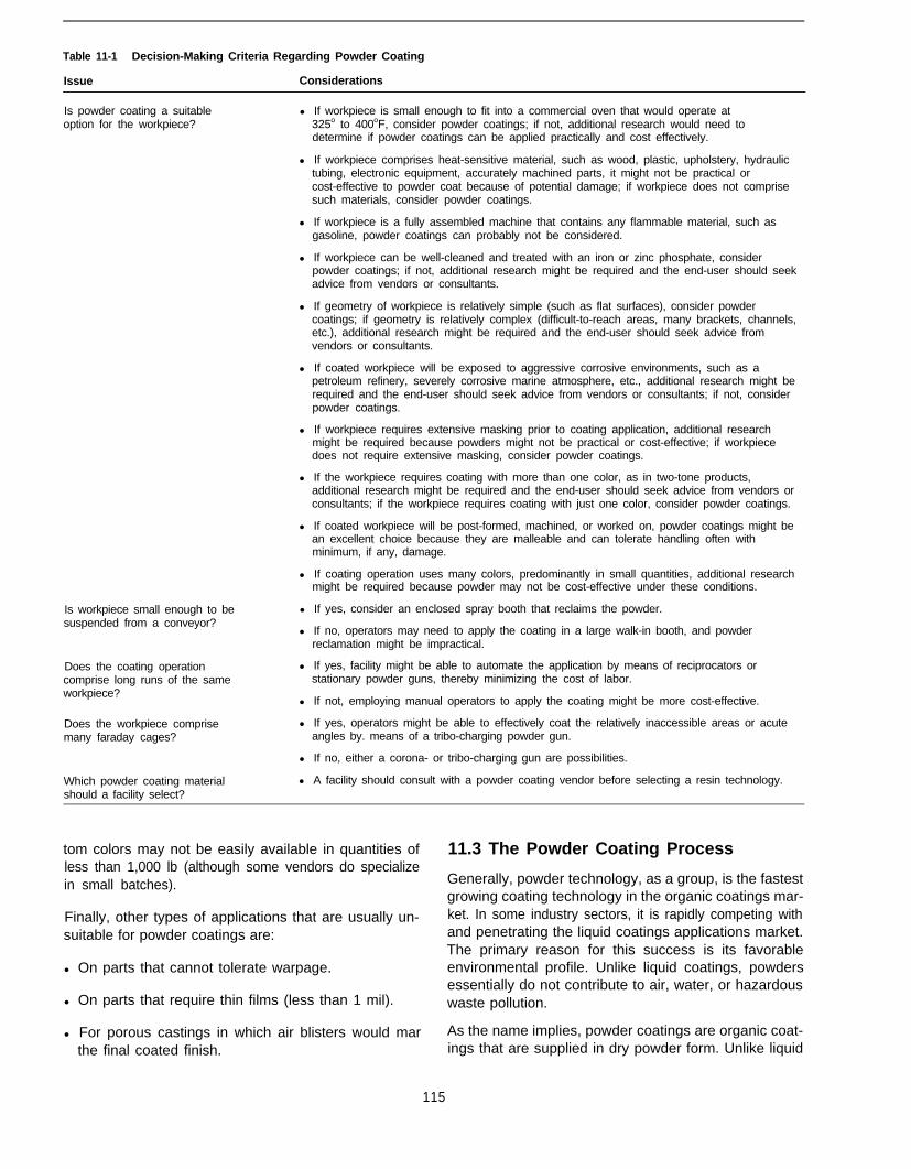
Table 11-1 Decision-Making Criteria Regarding Powder Coating
Issue Considerations
Is powder coating a suitableoption for the workpiece?
l If workpiece is small enough to fit into a commercial oven that would operate at325o to 400oF, consider powder coatings; if not, additional research would need todetermine if powder coatings can be applied practically and cost effectively.
l If workpiece comprises heat-sensitive material, such as wood, plastic, upholstery, hydraulictubing, electronic equipment, accurately machined parts, it might not be practical orcost-effective to powder coat because of potential damage; if workpiece does not comprisesuch materials, consider powder coatings.
l If workpiece is a fully assembled machine that contains any flammable material, such asgasoline, powder coatings can probably not be considered.
l If workpiece can be well-cleaned and treated with an iron or zinc phosphate, considerpowder coatings; if not, additional research might be required and the end-user should seekadvice from vendors or consultants.
l If geometry of workpiece is relatively simple (such as flat surfaces), consider powdercoatings; if geometry is relatively complex (difficult-to-reach areas, many brackets, channels,etc.), additional research might be required and the end-user should seek advice fromvendors or consultants.
l If coated workpiece will be exposed to aggressive corrosive environments, such as apetroleum refinery, severely corrosive marine atmosphere, etc., additional research might berequired and the end-user should seek advice from vendors or consultants; if not, considerpowder coatings.
l If workpiece requires extensive masking prior to coating application, additional researchmight be required because powders might not be practical or cost-effective; if workpiecedoes not require extensive masking, consider powder coatings.
l If the workpiece requires coating with more than one color, as in two-tone products,additional research might be required and the end-user should seek advice from vendors orconsultants; if the workpiece requires coating with just one color, consider powder coatings.
l If coated workpiece will be post-formed, machined, or worked on, powder coatings might bean excellent choice because they are malleable and can tolerate handling often withminimum, if any, damage.
l If coating operation uses many colors, predominantly in small quantities, additional researchmight be required because powder may not be cost-effective under these conditions.
Is workpiece small enough to besuspended from a conveyor?
l If yes, consider an enclosed spray booth that reclaims the powder.
l If no, operators may need to apply the coating in a large walk-in booth, and powderreclamation might be impractical.
Does the coating operationcomprise long runs of the sameworkpiece?
Does the workpiece comprisemany faraday cages?
Which powder coating materialshould a facility select?
l If yes, facility might be able to automate the application by means of reciprocators orstationary powder guns, thereby minimizing the cost of labor.
l If not, employing manual operators to apply the coating might be more cost-effective.
l If yes, operators might be able to effectively coat the relatively inaccessible areas or acuteangles by. means of a tribo-charging powder gun.
l If no, either a corona- or tribo-charging gun are possibilities.
l A facility should consult with a powder coating vendor before selecting a resin technology.
tom colors may not be easily available in quantities of 11.3 The Powder Coating Processless than 1,000 lb (although some vendors do specializein small batches). Generally, powder technology, as a group, is the fastest
growing coating technology in the organic coatings mar-Finally, other types of applications that are usually un- ket. In some industry sectors, it is rapidly competing withsuitable for powder coatings are: and penetrating the liquid coatings applications market.
The primary reason for this success is its favorablel On parts that cannot tolerate warpage. environmental profile. Unlike liquid coatings, powders
l On parts that require thin films (less than 1 mil).essentially do not contribute to air, water, or hazardouswaste pollution.
l For porous castings in which air blisters would mar As the name implies, powder coatings are organic coat-the final coated finish. ings that are supplied in dry powder form. Unlike liquid
115

coatings, each discrete powder particle contains theentire coating formulation, namely the resins, pigments,fillers, and modifiers. A powder coating contains no sol-vents. The powder particles are extremely finely dividedand resemble talcum powder.
The powder coating process entails two basic steps:
l Applying the coating onto a pretreated part
l Curing the coated part in an oven
11.3.1 Applying the Coating
Operators can use one of three primary methods toapply the powder coating:
l Electrostatic attraction by corona charge
l Electrostatic attraction using tribo-charging guns
l Fluidized bed
In both of the electrostatic methods, the parts to becoated are suspended from an electrically groundedconveyor.
The first method listed is the most common. To chargethe powder, the operator uses a gun that contains ahigh-voltage electrode. Upon pulling the gun trigger, thehigh electrical potential around the electrode ionizesthe surrounding air, causing a corona. As powder parti-cles leave the gun and pass through the charged air,the electrostatic charges transfer to the powder parti-cles, which then become attracted to the grounded part.The individual particles essentially “adhere” loosely tothe metal substrate; at this stage, the only mechanismparticles use to adhere to the substrate, or to each other,is electrostatic attraction.
The second application method also uses a gun, but onethat comprises internal passages made of plastic, usu-ally nylon. As the powder particles rub over the plastic,they receive an electrostatic charge, much like the phe-nomenon that occurs when running a comb throughone’s hair on a dry day. Once again, when the particlesleave the gun, they seek the grounded part and looselyadhere to it by electrostatic attraction.
In the fluidized bed approach, the powder is containedin a tank. The bottom of the tank comprises a porousplate. Low pressure air passes through the plate causingthe powder to become suspended in the air as a cloud.In fact, this cloud is known as a fluidized bed. The partto be coated must be preheated to a temperature usuallyin excess of 400oF, and is immediately immersed intothe fluidized bed. Upon contact, the powder particlesmelt and remain on the heated substrate. The higher thepar-t temperature or the longer the part remains in thefluidized bed, the heavier the film build. This assumesthat the temperature of the part does not drop to belowthe melting point of the powder.
Note that none of these methods involve solvents orgenerate hazardous waste. Also, clean-up efforts areminimal, benefitting both pollution prevention and timeand material resources.
Regardless of which method operators use to apply thecoating, the coated part must then enter an oven. In theoven, the powder melts, fuses, and cures into a hard,chemical- and abrasion-resistant coating.
11.3.2 Curing the Coated Part
Curing of the powder entails heating the powder-coatedpart in a convection oven at a temperature of between325°F and 400°F (163o to 204°C) for approximately 8 to20 minutes. Developments are underway to lower thecuring temperatures to 250°F (121°C). Two variablesthat affect the curing period are time and temperature.For instance, the lower the curing temperature, thelonger the curing time, and vice versa. Another variableaffecting the curing period is the mass of the part.
An alternate method for curing the powder uses aninfrared oven, which heats only those surfaces that areexposed directly to the infrared rays (i.e., the coating).The advantage of infrared curing is that the entire work-piece does not have to reach the curing temperature inorder for curing to take place. Because of this fact,infrared curing can provide cost savings.
When the powder coating is oven cured, some vapors-approximately 0.5 to 5 percent by weight of powdercoating-are emitted into the atmosphere. These com-prise mainly water and some organics. The organics arenot solvents, but rather plasticizers or resins emitted atthe high baking temperatures. To a large extent, theemitted vapors that have high boiling points condenseon the oven walls as they pass through it. It is question-able whether they are truly VOCs as defined by EPA. Infact, most air pollution regulatory agencies assume thatthe emissions from powder coating operations are es-sentially zero; therefore, operators are usually not re-quired to measure or record their emissions. In additionto advancing pollution prevention, this is a major eco-nomic benefit.
As soon as the part leaves the oven and cools to ambi-ent temperature, it can be handled, worked on, andshipped.
The fully cured coating is extremely hard and abrasion-resistant, and exhibits excellent physical properties. De-pending on the resin system, the coating can also beresistant to chemicals, solvents, sunlight, and most ofthe other chemical properties that are associated withhigh-performance liquid coatings.
116
11.4 Costs Associated With PowderCoating
For a facility operator considering either switching to oradding powder coating capabilities, cost analysis ofequipment and other requirements should encompassthe following areas:
General and environmentally related costs
Costs of materials
Pretreatment costs
Costs associated with actual coating process
Costs associated with heating/curing
Most importantly, regarding pollution prevention oppor-tunities in powder coating facilities, major cost savingsare probable in the area of environmental compliance.For instance, one company recently calculated an an-nual cost of hazardous waste disposal for its liquidcoatings to be in the order of $30,000. By converting topowders, that cost would essentially drop to zero. Simi-larly, the conversion would dramatically reduce costsassociated with obtaining air permits, administeringemissions inventories, etc.
Converting to a powder coating application, however,would require that the operators learn how to use thesecoatings. Any training costs, however, should be offsetby the fact that applying powder coatings is less compli-cated than applying liquid coatings. For expertise, how-ever, the facility operator may decide to hire a relativelyexperienced supervisor to oversee the operation.
Regarding materials, when coating the same number ofworkpieces, the costs for liquids and powders are some-what comparable. Liquid coatings are purchased by thegallon, while powders are purchased by the pound. Therule of thumb in the industry is to equate 3 pounds ofpowder to 1 gallon of liquid coating. Powders range incost from $2.50 to approximately $6.00 per pound, de-pending on the resin type, color, texture, etc. Exoticpowders are more expensive. Alternately, costs for liquidcoatings can vary from $10.00 per gallon for some of thelow-end resin formulations to $90.00 per gallon for poly-urethanes. Costs for some polyurethanes in exotic col-ors can even exceed $150 per gallon. While it may bedifficult to make a cost comparison based on the perpound versus per gallon measures, the industry’s ruleof thumb is to assume that for the majority of scenarios,the cost solely of the coating materials are approxi-mately the same.
The cost of equipment, of course, depends on the de-gree of sophistication of the facility. Most pretreatmentrequirements, however, are universal. The facility willneed a pretreatment system at least comparable to thatwhich a high-performance liquid coating system re-
quires. If the facility already has a 3- or 5-stage iron orzinc phosphating system for steel parts or a conversioncoating system for aluminum parts, no new pretreatmentequipment is necessary. Alternately, a facility lackingsuch equipment would have to install it. The costs toinstall a pretreatment system vary according to size andthroughput of material, but for most painting facilities therange is usually $50,000 to $120,000. Of course, afacility operator intending to install a pretreatment sys-tem in order to apply powders would also need to do sofor liquid coating application. In the past, many liquidcoating painting facilities could avoid the installation ofa sophisticated pretreatment system because the high-VOC liquid coatings were somewhat tolerant to surfacecontamination, With the introduction of high solids andwater-borne coatings, however, this is no longer true;therefore, with current technologies, liquid or powder, asophisticated pretreatment system is necessary.
Unlike the pretreatment phase, the actual powder coat-ing process is associated with many options. Pans canbe coated on conveyors or racks and, provided thatliquid and powder coatings are not applied on the sameline, it may be possible to use existing conveyor or rackequipment.
Spray guns and associated application and electroniccontrol equipment can cost from $5,000 to $100,000 perfacility. Portable units are available for companies thatuse only small quantities of powder or that coat on anintermittent basis.
If a facility uses a few standard colors in reasonablylarge quantities, the operator can feasibly purchase onededicated powder coating booth for each color. Whenthe facility is using a specific color, that particular boothis rolled in-line with the conveyor system.
In addition, a device is necessary to filter the overspraypowder from the exhaust air. Cartridge filters, or cy-clone/bag houses may be appropriate for this purpose.
If a facility operator intends to use both liquid and pow-der coatings, then the operator may consider having twoseparate dedicated coating lines: one for liquid and onefor powder. This, however, might require more facilityfloor space.
If, on the other hand, the facility operator intends toreplace its liquid coatings with powder coatings, then amajor retrofitting may be necessary. This would requirea shut-down period for the powder coating equipment tobe installed.
The final step of the powder coating process involvesheating and curing the coated piece. This step requiresovens, but because solvents do not evaporate from thecoatings, only low air replenishment is required. Theoven, which can be a convection, infrared, or similartype, must be capable of raising the coating temperature
117

to approximately 325°F to 400°F (163°C to 204°C).Some cases may require higher oven temperature, par-ticularly when using special high-performance coatingssuch as nylon.
Generally, however, energy costs are considerablyhigher for powders because these coatings cure at ele-vated temperatures. These costs, though, must be bal-anced against savings realized from emitting nosolvents.
11.4.1 Profiles of Economic Impact ofSwitching to Powders
Case histories of the economic and environmentalbenefits of powder versus liquid abound in the literature.Monthly or bi-monthly journals such as Powder CoatingJournal, Metal Finishing, Products Finishing, IndustrialPaint and Powder (formerly Industrial Finishing), regu-larly publish case histories demonstrating the advan-tages of the dry versus the wet technologies. Each yearin the United States, at least two national conferencesare devoted to powder coatings. Examples of typicalcases are presented below.
First, in most cases, a clear economic advantage existsfor converting from liquid to powder coatings (1). TheReturn on Investment (ROI) results in a short paybackperiod. Liberto reports that American Yard Products,producers of walk-behind and riding mowers, enjoyedsubstantial cost savings. The company’s total powderconversion investment was $2,150,000. When compar-ing this cost with the company’s annual operating costreduction from powders, which was $2,354,870, it isclear that the benefits in this case were dramatic. Theywere also quick; the projected payoff period was onlyabout 11 months (1).
The next profile is of the Self-Serve Fixture Company ofTexas, which manufactures a line of shelving and fix-tures for the self-serve retail market. It switched to pow-der in January 1991 and within the first year savedapproximately $100,000 solely on material usage. In itsprevious liquid painting operation the company esti-mated a transfer efficiency of 40 percent, which impliesthat 60 percent was wasted. Changing to powder led toa significant improvement; it realized 85 percent effi-ciency for colors that could be reclaimed and recycled,and 55 to 60 percent for custom colors for which it wasnot economical to reclaim the powder. The improvedquality of the finish contributed to a 20-percent increasein sales in 1992, and the president of the companyprojected another 15 percent for 1993 (2).
American Desk, a leading manufacturer of business andinstitutional furniture, had been using high solids, sol-vent-borne coatings. In 1993, the company partially con-verted to powder due to high environmental costs, wastedisposal, and high solvent throughput. Their new pow-
der coating system comprised a 5-stage washer, 6-min-ute dry-off oven, 2 powder coating booths, 28 powderguns, and a 25-minute bake oven. Bailey reports thatbecause of the increased line speed and improved partshanging technique, the powder coating system was ableto increase productivity by 50 to 100 percent. Moreover,the powder coating line, which operates two shifts perday, produces more than the previous liquid paintingsystem that required three shifts (3).
Maytag-Galesburg, manufacturer of refrigeration prod-ucts, converted to powder in 1992 as a voluntary effortto comply with EPA’s “33/50” initiative. This initiativecalled on large companies to voluntarily reduce theiremissions of 17 listed toxic chemicals by 50 percentbefore the end of 1995. According to Schrantz, thischange allowed the company to increase its productioncapacity. At least one benefit was that the cost of rejector repair parts due to frequent handling during manufac-ture and assembly was dramatically reduced becauseof the increased durability of the polyester powder coat-ing (2).
11.5 Advantages and Limitations ofPowder Coatings
11.5.1 Advantages
Facilities considering using powder coatings have acomfortable range from which to choose their coatings.Powder coatings are available in several resin formula-tions: acrylic, polyurethane, epoxy, polyester, ep-oxy/polyester hybrids, TGIC, nylon, etc. This technologyalso offers a reasonable range of colored, clear, andtextured coatings. In addition, depending on the resinsystem, powders are available in various gloss levels.
These coatings are associated with other advantages,too. They have excellent physical performance proper-ties, and many powders have excellent machinability aswell. Powders also are associated with excellent saltspray resistance. Partly because of these attractive fea-tures, military agencies are starting to accept powdercoating as replacement for liquids.
The largest advantages to a powder coating processderive from its application benefits and, especially, itspollution prevention benefits.
Regarding application, powder coatings allow operatorsto:
l Coat all sharp edges and cut ends.
l Provide thin to heavy film builds in one application(they usually require no primer).
l Apply coating to hot or cold parts.
Powder coatings also prove very economical for longruns of a few colors. They are especially adaptable to
118
robotic or reciprocating application and, generally re-quire less skill than application of liquid coatings.
Finally, another feature of applying powder coatings thatshould interest many facilities involves masking. Insome cases, masking is not required because uncuredpowder can be brushed off critical surfaces before thecoated part enters the curing oven.
The pollution prevention opportunities associated withpowder coatings, however, probably offer the greatestadvantages. These opportunities relate to high transferefficiencies, the cleanliness of the powder coating proc-ess, and the lack of hazardous waste.
Operators can achieve very high transfer efficiencieswith powder coatings. They can even attain transferefficiencies of greater than 95 percent if powder over-spray is collected and recycled.
In addition, powder coating is a relatively clean process,particularly if facilities operate spray booths under nega-tive pressure. Regarding clean-up, to a large extent anoperator can clean the spray booth using compressedair. Solvents may only be required during the final stageof cleaning.
Perhaps the most attractive advantages to powder coat-ings relate to their hazardous waste profile. Liquid coat-ings are applied in dry filter or water-wash spray booths,and either the filters or the wastewater require disposalas hazardous waste. Powder coatings, on the otherhand, are always applied in dry filter booths. The filters,however, generally do not require discarding. Instead,cartridge filters in modern powder coating booths aredesigned so that operators can reclaim the powders thatcollect in the filters. The filters are good for hundreds ifnot thousands of pounds of powder. Facilities caneventually dispose of the filters either as solid hazard-ous waste (if the entrapped powder contains heavymetals) or can discard them in a landfill.
l Emissions of almost zero VOC content (0.5 to 5 per-cent by weight).
l Minimal generation of hazardous waste (if any).
11.52 Limitations
As with all systems, powder coatings also have limita-tions. Some of these relate to heat requirements.
119
In addition, waste powder that might fall to the flooroutside the booth, can be swept up into a small pile,placed into an oven where it melts into a solid block, andbe discarded either as solid hazardous waste or in alandfill. The economic benefits from the environmentalconsiderations are sufficient reason for many facilities toconvert from liquids to powders.
This pollution prevention profile of powder coating trans-lates specifically into:
Most decorative resin systems require temperatures of325°F to 450°F (163°C to 204°C) for curing. Somefunctional resins require temperatures in excess of500°F. Apparently, however, some epoxies are availablethat only require 250°F (121°C). Because of theseneeds, powder coatings are associated with high energyusage.
Regarding personnel, although an earlier section de-scribed the powder coating process as uncomplicatedto perform, it does require a skilled operator to set upguns for each run, and check for quality before partsenter the oven. Also, powder coating often requiresmanual touch-up by an operator who stands at the endof an automated booth. Other quality-oriented tasks in-volve ensuring that the metal surfaces for coating havebeen well-cleaned and treated, as well as seeing thatthe oven remains clean so that dust and other contami-nants will not blow onto the coated parts during coating.
When considering the coating process itself, electro-static equipment makes it difficult to achieve high filmthicknesses (greater than 5 mil), unless the part is pre-heated prior to the coating application. Of course, mostcases do not require 5 mil. In addition, in fluidized bedapplications, operators cannot easily control film thick-ness due to differing heat contents of the metal assem-bly (i.e., light gauge metal fixed to casting).
Another example of challenges associated with the pow-der coating process involves the difficulties associatedwith coating “faraday cages” unless using alternativetechniques. A farady cage is the area inside an acuteangle that is shielded from the electrostatic field. Forinstance, if the inside of a box is to be powder coated,it might be difficult to deposit powder onto the insidecorners of the box. The inside surfaces of a channelbracket or the area between the fins of a radiator allrepresent faraday cages. Recent years have seen newmethods to overcome some of these problems. In par-ticular, the tribo-charging gun appears to successfullycoat many of these surfaces. Moreover, powder coat-ings can be more difficult to repair after curing whencompared to liquid coatings.
Finally, capital equipment outlay is generally greater forpowder coating than for conventional coatings ($5,000to $100,000). Small or portable systems are available,however, which are less expensive. Because each caseis different, the costs for converting to powder can becomparable to those for liquid coatings. Costs seem torise when a facility operator intends to use an automatedsystem.
11.6 References
1. Liberto, N.P. et al. 1990. Appliance Manufacturer. Business NewsPublishing Company, (March).

2. Schrantz, J. 1993. Powder saves $100,000 in first year. industrialFinishing 69(4):22-25 (April).
3. Bailey, J.M. 1994. Back to school with powder. Industrial Paintand Powder 70(9):14-16 (September).
11.7 Additional ReadingCollins, B. 1988. From wet to dry: Can it be done? The Finishing Line
4(4):3-5.
Dawson, S., and V. Reddy, eds. 1990. Powder coating applications,1st ed. Dearborn, Ml: Society of Manufacturing Engineers.
Liberto, N.P, ed. 1994. Powder coating: The complete finisher’s hand-book, 1st ed. Powder Coating Institute, Alexandria, VA.
Hart, J. 1988. Serving New England’s powder coating needs. Prod-ucts Finishing 52:60-64.
Joseph, Ft. 1994. Paints and coatings training program. Saratoga,CA: Ron Joseph & Associates, Inc.
Maguire, G. 1988. Fluoropolymer powder coatings on the move.Products Finishing 52:66-69.
Miller, E., ed. 1985. User’s guide to powder coating, 1st ed. Dearborn,Ml: Society of Manufacturing Engineers.
Muhlenkamp, M. 1988. High performance powder coatings for alumi-num. Products Finishing 5253-58.
The Powder Coating Institute, 1800 Diagonal Road, ste. 370, Alex-andria, VA. [Serves the powder coating industry and can providea wide range of information to prospective powder coating users.]
U.S. EPA. 1989. Powder coatings technology update. EPA/450/3-89133.
120

Chapter 12Viscosity Management for Pollution Prevention
12.1 Introduction
12.1.1 Pollution Prevention Considerations
This chapter discusses one of the most important prop-erties of a coating, namely viscosity. Viscosity is a meas-ure of the degree to which a fluid resists flow under anapplied force.
Controlling viscosity has an indirect yet important effecton pollution prevention. Best management practicesthat control viscosity do not, in and of themselves, di-minish air, water, and waste pollution. With proper vis-cosity management, however, operators can achievemore acceptable finishes, dramatically reducing thenumber of reworks and rejects. Repainting fewer work-pieces reduces all forms of pollution.
Coating manufacturers often attempt to formulate prod-ucts that can be used as packaged. Sometimes, how-ever, the spray painter must make adjustments, such asdiluting the coating, in order to obtain an acceptablefinish. Unfortunately, most spray painters do not fullyunderstand their options, and hence rejects and reworksabound, particularly with high solids coatings.
The purpose of this chapter is to provide a better under-standing of the available techniques for beneficially al-tering the viscosity of a coating.
Decision-making criteria relevant to viscosity manage-ment are not specifically called out in a table becausethe recommendations discussed throughout this chaptershould be followed by all facilities.
12.2 Description of Viscosity
A thorough understanding of the concept of viscosity aswell as the parameters that affect it can be very usefulin applying coatings efficiently and minimizing rejectsand reworks.
Consider a basic example. Water has a low viscositycompared with cold syrup. Upon heating, however, thesyrup’s viscosity drops and it flows more easily. This, ofcourse, is a simplistic example of viscosity. Because thesubject is more complex a few definitions may be helpful.
Absolute dynamic viscosity is the force per unit area thatresists the flow of two parallel fluid layers past oneanother when their differential velocity is 1 cm/set percentimeter separation (1). Figure 12-1 illustrates a liquidlying between two parallel plates (2). Suppose that the
Figure 12-1. The concept of viscosity (2).
tower plate is fixed, while the upper plate can move tothe right at a velocity (v) under the action of an externallyapplied force. With this movement, the liquid betweenthe two plates would distort as shown. One of the pa-rameters illustrated here is shear stress. By definitionshear stress is as follows:
where A is the area of the top plate and F representsthe force exerted on the top plate.
Another important parameter is shear strain, which is:
Figure 12-1 also shows how the velocity of the fluidchanges from zero at the lower plate to vat the upper.
121

Viscosity is usually expressed in terms of poise or cen-tipoise (cp), where:
The units of absolute viscosity, poise or centipoise, aregm/(cm)(second).
Finally, a measure of kinematic viscosity is given instokes, where:
Although most people will never have a need to performthe calculations presented in the preceding definitions,the calculations do illustrate a couple important points.First, they make clear the many variables that affectviscosity. Second, they lay the groundwork for under-standing much more commonly used definitions regard-ing viscosity. These common definitions follow.
A Newtonian liquid is any liquid for which the shearstress is proportional to the shear rate. If the ratio ofshear stress to shear rate is small and the effect onviscosity is not constant, the liquid is non-Newtonian (2).
For instance, when measuring the viscosity of water,which is a Newtonian liquid, the viscosity remains con-stant regardless of how fast it is stirred.
A near-Newtonian liquid is one for which the variation ofviscosity with shear rate is small and the effect onviscosity of mechanical disturbances, such as stirring, isnegligible.
A non-Newtonian liquid is any liquid that does not satisfythe requirements for a Newtonian liquid. Such liquidshave plastic flow, pseudo-plastic flow, or dilatant flow.For each of these, the shear rate is not proportional tothe shear stress.
For plastic flow, the liquid must overcome or exceed ayield stress before flow will take place. No yield valueexists for pseudo-plastic flow and the curve of the plotof shear stress versus shear rate is non-linear, with theshear rate increasing faster than the shear stress. Forfluids exhibiting dilatant flow, the viscosity increases asthe shear rate increases. The curve of the plot of shearstress versus shear rate is non-linear, with the shearstress increasing faster than the shear rate.
Finally, the consistency of thixotropic materials dependson the duration of shear as well as on the rate of shear.To better understand this property, one can imagine howthe viscosity of an acrylic latex paint changes as it isbeing stirred. For instance, when stirring the paint veryslowly with a stick or paddle, its viscosity is relativelyhigh. As stirring becomes faster and more vigorous, theviscosity drops. When stirring ceases altogether, theviscosity increases again, although it may not increaseto its original value. Figure 12-2 demonstrates the rela-tionship between viscosity and shear rate for a thixot-ropic fluid.
Figure 12-2. Thixotropy.
A coating with thixotropic properties may have a rela-tively high viscosity while being pumped from a pressurepot to the spray gun. As the coating is forced throughthe very small orifice of the gun, its viscosity dropsappreciably and remains relatively low while the parti-cles travel from the gun to the target. As they settle onthe target, such as a vertical panel, the viscosity rapidlybuilds up again, thus minimizing the possibility for thecoating to run or sag.
12.3 Measuring Viscosity
Viscosity is one of the most important coating propertiesin determining if the coating can be applied to an accept-able finish. This is why measuring viscosity is so important.
The most commonly used viscometers for measuring painton a production line are gravity type cups such as theseries of Zahn cups (#l, #2, #3, and #4) and the Ford cup(#2, #3, #4). All require little skill and can be used by paintoperators who have been shown how to use them.
12.3.1 Zahn Cup
The Zahn Cup is made of stainless steel and resemblesa cup as shown in Figure 12-3. It has a small orifice at
122

Figure 12-3. Zahn cups.
123
the bottom and a stainless steel handle braised to thetop which allows an operator to hold the cup during themeasurement. The operator first stirs or agitates thecoating to ensure proper homogeneity, and then care-fully immerses the cup itself into the body of the paint.The operator quickly withdraws the filled cup from thepaint, but loosely holds it only a few inches from the topof the coating container, ensuring that it hangs downvertically. The coating flows from the orifice of the cupback into the container.
Immediately after withdrawing the cup from the paint, astopwatch is started. As soon as the stream of paintbreaks, the operator stops the watch and records thereading. Provided that the coating stream undergoes aclean and single break, the viscosity of the coating ismeasured by the seconds the coating requires to effluxto the break point.
This method for measuring viscosity is easy to imple-ment, and is cost-effective because Zahn cups costapproximately $70 to $80 and require relatively little skill.
A disadvantage of the cup is that it is not suitable forhighly thixotropic coatings. With more viscous coatingsthe stream may break once, then flow again for a fewseconds and break again, and continue in this fashionuntil the last drop of paint effluxes from the cup. Many
spray painters record the viscosity measurement afterthe very first break, but this is inaccurate for thixotropiccoatings because the orifice of the cup is too small. Formore viscous coatings, operators should use a cup witha larger orifice, such as the Zahn #3 or Zahn #4. Table12-1 provides guidelines for selecting the correct cup.Remember that the most reliable viscosity is measuredwhen the coating makes only one break.
Table 12-1. Zahn Cup Orifice Sizes (3)
RecommendedApproximate Centistokes Range in Zahn
CUP Orifice Size (in.) Range (secs)
1 0.078 15 to 78 31 to 60
2 0.108 40 to 380 19to60
3 0.148 90 to 604 13 to 60
4 0.168 136 to 899 12to60
5 0.208 251 to 1,627 10 to 60
Another disadvantage of the Zahn cup is that when theoperator withdraws it from the coating, excess materialflows not only through the inside of the cup but alongthe walls on the outside. This influences the number ofseconds before the stream breaks.
For facilities that do not require precise viscosity control,Zahn cups are probably the most practical and the leastexpensive.
12.3.2 Ford Cup
The design of this stainless steel viscometer is alsobased on gravity feed, but it differs from the Zahn cupin that it incorporates a lip to collect excess coating.Moreover, the cup is not immersed in the coating but isheld in position in a specially designed stand which isplaced on a laboratory table top (see Figure 12-4). TheFord cup that the coatings industry most often uses isthe Ford #4 cup.
Before measurement begins, the temperature of thecoating is determined and recorded.
To measure viscosity, the operator collects a sample ofthe coating from its container or pressure pot and care-fully pours it into the Ford cup until the coating overflowsinto the lip. While doing this, the operator places a fingerunder the orifice of the cup to prevent coating fromeffluxing. Acontainer, such as a pint can, which is placedunder the cup collects the coating.
Upon readiness, the operator starts the stopwatch andremoves the finger from the orifice. Immediately, thecoating starts to efflux into the pint can. Once again, thestopwatch is stopped when the first break in the coatingstream occurs. Unlike the smaller Zahn cups, the orifice

ties of non-Newtonian fluids in the shear rate range of0.1 to 50 per second-’ (4).
Figure 12-4. Ford viscosity cups (photo courtesy of Pacific Sci-entific Catalog publisher).
in the Ford cup is usually large enough so that one cleanbreak takes place regardless of viscosity.
Although paint operators use the Ford cup less fre-quently than the Zahn cup, it is the standard method formeasuring viscosity in a paint manufacturing laboratory.It has the advantage that no coating flows down thewalls of the outside of the cup to interfere with theviscosity measurements. Facilities that use the paintsand coatings usually prefer the Zahn cup because it isless expensive and simpler to use (i.e., the operatorneed not transfer coating from the container or pressurepot to the cup).
If the coating is to be applied at an elevated tempera-ture, it is preferable to measure the viscosity at the sametemperature. This, however, may be impractical in manyfacilities. An alternative to measuring the viscosity at theapplication temperature is to measure it at ambient tem-perature, and then determine what viscosity is requiredunder ambient conditions to yield the desired applicationviscosity at application temperature.
12.3.3 Brookfield Viscometer
A major disadvantage of the gravity type viscometers is thatthey do not reflect the true viscosity of non-Newtonianand thixotropic coatings. Because many water-borneand some solvent-borne products fall into this category,the gravity type viscometers are inappropriate.
A Brookfield viscometer can determine the apparentviscosity and the shear thinning and thixotropic proper-
Three methods exist for characterizing the rheologicalproperties of the coating. The first consists of determin-ing the apparent viscosity of a coating by measuring thetorque on a spindle rotating at a constant speed. Unfor-tunately, this method only measures the viscosity at onerotational speed so one cannot fully understand thenon-Newtonian nature of the coating.
The second and third methods consist of determiningthe shear thinning and thixotropic (time-dependent)rheological properties of the coating by measuring vis-cosity at a series of rotational speeds of the spindle. Theagitation of the coating immediately before measuringthe viscosity is closely controlled. Measurements showthe correlation between the drop in viscosity with in-creasing rotational speed, and also the increase or re-covery in viscosity when lowering the rotational speed.When the shear rate is high, the behavior of the coatingunder true application conditions provides more accu-rate information as to how the coating will behave afterit has been applied.
When measuring only the apparent viscosity, the opera-tor uses a constant rotational velocity, usually 200 rpm.Brookfield viscometers contain a spindle or paddledesigned to rotate at this constant speed (see Figure12-5). The instrument then measures the energy re-quired to maintain this constant shear rate, and sincethe viscosity of thixotropic coatings is directly dependent
Figure 12-5. Brookfield viscometer (photo courtesy of PacificScientific Catalog publisher).
124
on the shear rate, the instrument is appropriate for thistype of measurement.
As with all viscosity measurements, the operator shouldmeasure viscosity at the application temperature. If thisis not possible, however, the viscosity can be measuredat a standard ambient temperature and viscosity canthen be extrapolated to the operating temperature.
Unlike the gravity type viscometers, the Brookfield in-struments do require a certain degree of skill to achieverepeatable results. These instruments are well worthusing, however, when the uniformity of film appearanceis critical, such as in the automotive industry.
12.4 Guidelines for Best ManagementPractices (BMPs)
As stated earlier, properly managing viscosity preventspollution by limiting the number of rejects and reworks.Fewer rejects and reworks means less materials, lesswaste, and less pollution, as well as less cost. BMPs forcontrolling viscosity include the following:
Measuring viscosity.
Maintaining constant temperature.
Drawing a viscosity/temperature chart.
Specifying an acceptable range of viscosities.
Developing alternatives for achieving acceptablefinishes.
Using heat to reduce viscosity.
Minimizing waste disposal by choosing appropriatemixing procedure.
Recognizing thixotropic properties of water-bornesolvents.
12.4.7 Measuring Viscosity and Temperature
Measurement of viscosity by the paint operator shouldnot be optional because this coating property helpsdetermine whether the operator can achieve an accept-able finish. In measuring viscosity, the operator shouldalso measure the temperature of the coating.
To ensure constant viscosity throughout the workingday, the spray booth and the coating in the fluid hoseleading to the spray gun should remain at a constanttemperature. This can be accomplished in one of twoways:
l A facility may opt to use an air make-up unit to controlthe inlet air to the spray booth, but must consider thecost of heating the air. Large spray booths, particu-larly downdraft ones, have high air throughputs (usu-ally well in excess of 20,000 cfm) so the cost ofenergy is high. Many paint facilities, particularly those
in cold climates, already have air make-up units in-stalled.
l The facility can heat the coating to a constant tem-perature, usually above ambient. Even facilities withair make-up units on their spray booths can benefitbecause the coating must often travel to the boothfrom a mixing room that may be quite a distance fromthe booth. The coating that reaches the booth fromthe uncontrolled mixing room may be cold in themorning and warm in the afternoon.
An operator should draw a viscosity/temperature chartbefore qualifying or using any coating for the first time.Measuring the viscosity of the coating at progressivelyhigher temperatures accomplishes this. The operatormust ensure, however, that solvent does not evaporatefrom the coating while it heats.
The procedure for preparing a viscosity/temperaturechart using a Zahn cup follows:
1.
2.
3.
4.
Mix the coating thoroughly before sampling.
Fill a quart can with the coating and measure thetemperature, and then determine its viscosity withthe appropriate Zahn cup. (Clean the cup beforereusing.)
Take the lid from the can and punch a small holethrough the center. Insert an impeller or paddlethrough the hole and replace the lid on the container.Then place the can in a larger container of warmwater. Thoroughly stir the coating and measure thetemperature. After the temperature rises by anappropriate amount, such as 5oF, measure theviscosity again. Continue in this fashion, alwaysadding warmer water to the outer container, untilseveral points can be plotted on a chart.
If the ambient temperature is too warm, add ice tothe outer container to cool down the coating belowambient.
The viscosity/temperature chart is very useful becauseit allows the spray painter to interpolate or extrapolatethe appropriate viscosity when mixing the coating at thebeginning of the shift. For instance, if the paint is coldwhen starting in the morning, instead of adding solventto lower the viscosity, the spray painter can set thein-line heater to the temperature that yields the mostappropriate application viscosity.
12.4.2 Specifying a Viscosity Range
The coating facility should specify an acceptable narrowrange of viscosities that are compatible with the sprayequipment. Thereafter, quality control tests on incomingmaterial should ensure that the coating vendor suppliesthe same viscosity from batch to batch. If end-users donot perform such tests, they can expect batch to batch

viscosity differences. This may not make a noticeabledifference for manual spray gun applications but it willaffect the finishes produced by automated guns,whether on reciprocators or on robots. Viscosity controlis critical when applying metallic coatings; otherwise,apparent color differences can lead to rejects or re-works.
12.4.3 Developing Acceptable Alternatives
If the coating is VOC compliant but the spray gun cannotachieve an acceptable finish, several alternatives areavailable. One alternative might be to experiment withdifferent spray guns. For instance, if currently using anHVLP gun the end-user should experiment with HVLPguns from other vendors. If this does not solve theproblem, trying different spray gun types, such as air-as-sisted airless or electrostatic, may help.
Also, if the coating is a single-component formulation,such as an air/force dry coating, or one that bakes at anelevated temperature, the end-user should experimentwith a closed loop, recirculating, in-line paint heater. Theadvantage of heat is that it not only lowers the viscosityof the coating but also tends to produce a more uniformfinish.
12.4.4 Using Heat To Reduce viscosity
Although this topic is closely associated with the prac-tice just described, its importance cannot be overstated.The use of heat rather than solvents to reduce viscosityis one of the most effective strategies for minimizingsolvent emissions into the air. Facilities should considerin-line paint heaters for both water-borne and solvent-borne, single-component coatings. The end-user mustdiscuss with the paint manufacturer the efficacy of usingheat to adjust viscosity of the coating. The manufacturercan determine whether heat will be beneficial. Paintheaters are discussed in more detail in Section 12.7.3.
12.4.5 Minimizing Waste Disposal
To minimize the disposal of waste from mixed plural-component coatings, a facility should carefully considerthe manner in which the coating is mixed. Chapter 10provides several guidelines but a summary follows.
12.4.5.1 Batch Mixing
For small batches, usually less than 1 gallon, it probablyis best to premix the components in batches rather thanto install a proportioner and mixing device. When usingmany colors in small quantities, usually less than 1gallon, it also probably makes more sense to premix thecomponents. When selecting the premix option, thespray painter should mix only as much coating as thejob requires.
Pot life is the time that elapses after a plural-componentcoating has been mixed, until its viscosity is so high thatthe operator can no longer achieve an acceptable finish.If the coating has a short pot life, the spray paintershould mix only as much coating as can be appliedbefore reaching the pot life. If the pot life needs to belonger in order to avoid wasting valuable material, theoperator can cool the coating but should not chill it to atemperature that will cause condensation of moisturefrom the air to settle on the surface of the mixed coating.
Pot life should not be extended by adding solvent to themixed coating. Not only may this cause the coating toexceed the regulated VOC limit, but the solvent mayremain entrapped in the applied coating and lead topaint failures several months or years after the coatinghas been applied.
12.4.5.2 In-Line Mixing
When a facility uses relatively large volumes of plural-component coatings, such as epoxies and polyure-thanes, it might be beneficial to install proportioningequipment. Such equipment is designed to continuouslymeasure the exact ratios of the components being fedto the spray gun. For instance, an epoxy might be mixedin the ratio of 4 parts component A, 1 part component B,and l/2 part thinner.
A small stainless steel or plastic static mixer is insertedinto the fluid hose only a foot or so upstream from thespray gun. A static mixer is nothing more than a shorttube, approximately 8 inches long and with a diameterof about 3/4 of an inch. On the inside of the tube are aseries of baffles that force the coating to repeatedlychange direction as it passes through the tube. As theunmixed components enter the static mixer, the bafflescause extensive turbulence of the components, so thatwhen they emerge from the mixing tube, they have beenthoroughly mixed.
This strategy is probably the most effective for minimiz-ing air, waste, and water pollution, and for cutting thecosts associated with the disposal of the waste material.The cost to install a proportioner and mixing device willbe offset by the savings. A facility can expect a cost-pay-back within a few months, depending on the quantitiesof coatings used.
Proportioners are ideal when using relatively largequantities, usually larger than 1 gallon, of a single coloron a regular basis. They can be justified even whenusing many colors, but the quantity of each color mustbe large enough to warrant the use of the equipment.
12.4.6 Recognizing Thixotropic Properties
When using water-borne coatings, the spray paintershould try to apply them at the highest viscosity that willgive an acceptable finish. The spray painter should have
126
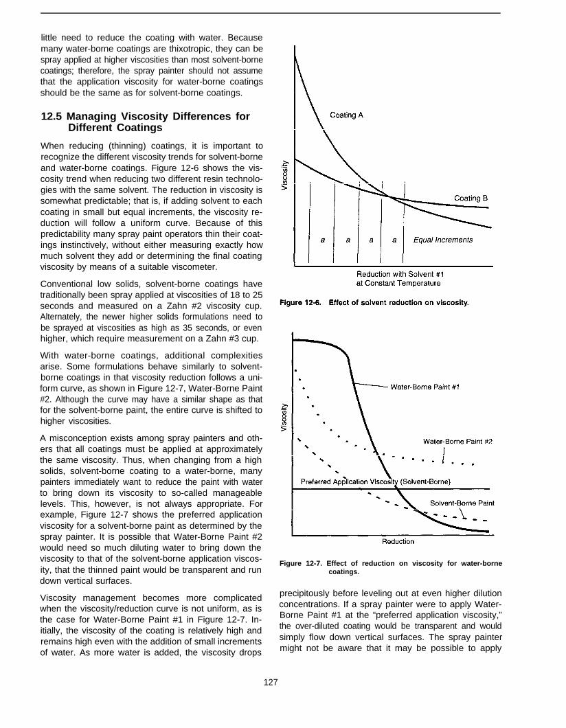
little need to reduce the coating with water. Becausemany water-borne coatings are thixotropic, they can bespray applied at higher viscosities than most solvent-bornecoatings; therefore, the spray painter should not assumethat the application viscosity for water-borne coatingsshould be the same as for solvent-borne coatings.
12.5 Managing Viscosity Differences forDifferent Coatings
When reducing (thinning) coatings, it is important torecognize the different viscosity trends for solvent-borneand water-borne coatings. Figure 12-6 shows the vis-cosity trend when reducing two different resin technolo-gies with the same solvent. The reduction in viscosity issomewhat predictable; that is, if adding solvent to eachcoating in small but equal increments, the viscosity re-duction will follow a uniform curve. Because of thispredictability many spray paint operators thin their coat-ings instinctively, without either measuring exactly howmuch solvent they add or determining the final coatingviscosity by means of a suitable viscometer.
Conventional low solids, solvent-borne coatings havetraditionally been spray applied at viscosities of 18 to 25seconds and measured on a Zahn #2 viscosity cup.Alternately, the newer higher solids formulations need tobe sprayed at viscosities as high as 35 seconds, or evenhigher, which require measurement on a Zahn #3 cup.
With water-borne coatings, additional complexitiesarise. Some formulations behave similarly to solvent-borne coatings in that viscosity reduction follows a uni-form curve, as shown in Figure 12-7, Water-Borne Paint#2. Although the curve may have a similar shape as thatfor the solvent-borne paint, the entire curve is shifted tohigher viscosities.
A misconception exists among spray painters and oth-ers that all coatings must be applied at approximatelythe same viscosity. Thus, when changing from a highsolids, solvent-borne coating to a water-borne, manypainters immediately want to reduce the paint with waterto bring down its viscosity to so-called manageablelevels. This, however, is not always appropriate. Forexample, Figure 12-7 shows the preferred applicationviscosity for a solvent-borne paint as determined by thespray painter. It is possible that Water-Borne Paint #2would need so much diluting water to bring down theviscosity to that of the solvent-borne application viscos-ity, that the thinned paint would be transparent and rundown vertical surfaces.
Viscosity management becomes more complicatedwhen the viscosity/reduction curve is not uniform, as isthe case for Water-Borne Paint #1 in Figure 12-7. In-itially, the viscosity of the coating is relatively high andremains high even with the addition of small incrementsof water. As more water is added, the viscosity drops
Figure 12-7. Effect of reduction on viscosity for water-bornecoatings.
precipitously before leveling out at even higher dilutionconcentrations. If a spray painter were to apply Water-Borne Paint #1 at the “preferred application viscosity,”the over-diluted coating would be transparent and wouldsimply flow down vertical surfaces. The spray paintermight not be aware that it may be possible to apply
127
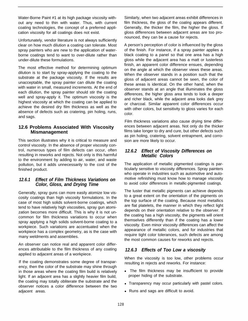
Water-Borne Paint #1 at its high package viscosity with-out any need to thin with water. Thus, with currentcoating technologies, the concept of a preferred appli-cation viscosity for all coatings does not exist.
Unfortunately, vendor literature is not always sufficientlyclear on how much dilution a coating can tolerate. Mostspray painters who are new to the application of water-borne coatings tend to want to over-dilute rather thanunder-dilute these formulations.
The most effective method for determining optimumdilution is to start by spray-applying the coating to thesubstrate at the package viscosity. If the results areunacceptable, the spray painter can dilute the coatingwith water in small, measured increments. At the end ofeach dilution, the spray painter should stir the coatingwell and spray-apply it. The optimum viscosity is thehighest viscosity at which the coating can be applied toachieve the desired dry film thickness as well as theabsence of defects such as cratering, pin holing, runs,and sags.
12.6 Problems Associated With ViscosityMismanagement
This section illustrates why it is critical to measure andcontrol viscosity. In the absence of proper viscosity con-trol, numerous types of film defects can occur, oftenresulting in reworks and rejects. Not only is this harmfulto the environment by adding to air, water, and wastepollution, but it adds unnecessarily to the cost of thefinished product.
12.6.1 Effect of Film Thickness Variations onColor, Gloss, and Drying Time
Generally, spray guns can more easily atomize low vis-cosity coatings than high viscosity formulations. In thecase of most high solids solvent-borne coatings, whichtend to have relatively high viscosities, spray gun atomi-zation becomes more difficult. This is why it is not un-common for film thickness variations to occur whenspray applying a high solids solvent-borne coating to aworkpiece. Such variations are accentuated when theworkpiece has a complex geometry, as is the case withmany weldments and assemblies.
An observer can notice real and apparent color differ-ences attributable to the film thickness of any coatingapplied to adjacent areas of a workpiece.
If the coating demonstrates some degree of transpar-ency, then the color of the substrate may shine throughin those areas where the coating film build is relativelylight. If an adjacent area has a slightly heavier film build,the coating may totally obliterate the substrate and theobserver notices a color difference between the twoadjacent areas.
Similarly, when two adjacent areas exhibit differences infilm thickness, the gloss of the coating appears different.Generally, the thicker the film, the higher the gloss. Ifgloss differences between adjacent areas are too pro-nounced, they can be a cause for rejects.
A person’s perception of color is influenced by the glossof the finish. For instance, if a spray painter applies ablack coating to a panel so that one area has a highgloss while the adjacent area has a matt or lusterlessfinish, an apparent color difference ensues, dependingon the angle at which the observer views these areas.When the observer stands in a position such that thegloss of adjacent areas cannot be seen, the color ofthese areas is identical. On the other hand, when theobserver stands at an angle that illuminates the glossdifferences, the higher gloss area tends to look a deeperand richer black, while the adjacent area looks dark greyor charcoal. Similar apparent color differences occurwith other colors, but sensitivity to gloss varies for eachcolor.
Film thickness variations also cause drying time differ-ences between adjacent areas. Not only do the thickerfilms take longer to dry and cure, but other defects suchas pin holing, cratering, solvent entrapment, and corro-sion are more likely to occur.
12.6.2 Effect of Viscosity Differences onMetallic Colors
The application of metallic pigmented coatings is par-ticularly sensitive to viscosity differences. Spray painterswho operate in industries such as automotive and auto-motive refinishing must know how to manage viscosityto avoid color differences in metallic-pigmented coatings.
The luster that metallic pigments can achieve dependsto a great extent on the orientation of the pigments onthe top surface of the coating. Because most metallicsare flat platelets, the manner in which they reflect lightdepends on their orientation relative to the observer. Ifthe coating has a high viscosity, the pigments will orientthemselves differently than if the coating has a lowerviscosity. Even minor viscosity differences can affect theappearance of metallic colors, and for industries thatrequire tight color tolerances, such defects are amongthe most common causes for reworks and rejects.
12.6.3 Effects of Too Low a viscosity
When the viscosity is too low, other problems occurresulting in rejects and reworks. For instance:
l The film thickness may be insufficient to provideproper hiding of the substrate.
l Transparency may occur particularly with pastel colors.
l Runs and sags are difficult to avoid.
128
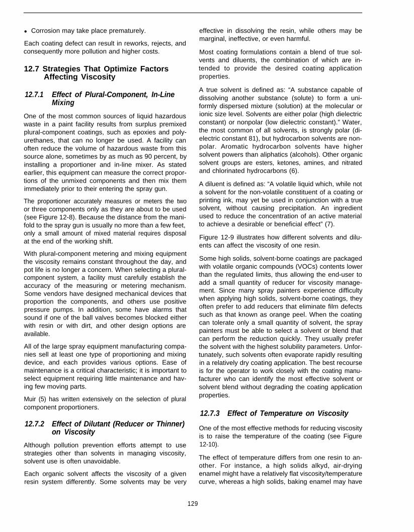
l Corrosion may take place prematurely.
Each coating defect can result in reworks, rejects, andconsequently more pollution and higher costs.
12.7 Strategies That Optimize FactorsAffecting Viscosity
12.7.1 Effect of Plural-Component, In-LineMixing
One of the most common sources of liquid hazardouswaste in a paint facility results from surplus premixedplural-component coatings, such as epoxies and poly-urethanes, that can no longer be used. A facility canoften reduce the volume of hazardous waste from thissource alone, sometimes by as much as 90 percent, byinstalling a proportioner and in-line mixer. As statedearlier, this equipment can measure the correct propor-tions of the unmixed components and then mix themimmediately prior to their entering the spray gun.
The proportioner accurately measures or meters the twoor three components only as they are about to be used(see Figure 12-8). Because the distance from the mani-fold to the spray gun is usually no more than a few feet,only a small amount of mixed material requires disposalat the end of the working shift.
With plural-component metering and mixing equipmentthe viscosity remains constant throughout the day, andpot life is no longer a concern. When selecting a plural-component system, a facility must carefully establish theaccuracy of the measuring or metering mechanism.Some vendors have designed mechanical devices thatproportion the components, and others use positivepressure pumps. In addition, some have alarms thatsound if one of the ball valves becomes blocked eitherwith resin or with dirt, and other design options areavailable.
129
All of the large spray equipment manufacturing compa-nies sell at least one type of proportioning and mixingdevice, and each provides various options. Ease ofmaintenance is a critical characteristic; it is important toselect equipment requiring little maintenance and hav-ing few moving parts.
Muir (5) has written extensively on the selection of pluralcomponent proportioners.
12.7.2 Effect of Dilutant (Reducer or Thinner)on Viscosity
Although pollution prevention efforts attempt to usestrategies other than solvents in managing viscosity,solvent use is often unavoidable.
Each organic solvent affects the viscosity of a givenresin system differently. Some solvents may be very
effective in dissolving the resin, while others may bemarginal, ineffective, or even harmful.
Most coating formulations contain a blend of true sol-vents and diluents, the combination of which are in-tended to provide the desired coating applicationproperties.
A true solvent is defined as: “A substance capable ofdissolving another substance (solute) to form a uni-formly dispersed mixture (solution) at the molecular orionic size level. Solvents are either polar (high dielectricconstant) or nonpolar (low dielectric constant).” Water,the most common of all solvents, is strongly polar (di-electric constant 81), but hydrocarbon solvents are non-polar. Aromatic hydrocarbon solvents have highersolvent powers than aliphatics (alcohols). Other organicsolvent groups are esters, ketones, amines, and nitratedand chlorinated hydrocarbons (6).
A diluent is defined as: “A volatile liquid which, while nota solvent for the non-volatile constituent of a coating orprinting ink, may yet be used in conjunction with a truesolvent, without causing precipitation. An ingredientused to reduce the concentration of an active materialto achieve a desirable or beneficial effect” (7).
Figure 12-9 illustrates how different solvents and dilu-ents can affect the viscosity of one resin.
Some high solids, solvent-borne coatings are packagedwith volatile organic compounds (VOCs) contents lowerthan the regulated limits, thus allowing the end-user toadd a small quantity of reducer for viscosity manage-ment. Since many spray painters experience difficultywhen applying high solids, solvent-borne coatings, theyoften prefer to add reducers that eliminate film defectssuch as that known as orange peel. When the coatingcan tolerate only a small quantity of solvent, the spraypainters must be able to select a solvent or blend thatcan perform the reduction quickly. They usually preferthe solvent with the highest solubility parameters. Unfor-tunately, such solvents often evaporate rapidly resultingin a relatively dry coating application. The best recourseis for the operator to work closely with the coating manu-facturer who can identify the most effective solvent orsolvent blend without degrading the coating applicationproperties.
12.7.3 Effect of Temperature on Viscosity
One of the most effective methods for reducing viscosityis to raise the temperature of the coating (see Figure12-10).
The effect of temperature differs from one resin to an-other. For instance, a high solids alkyd, air-dryingenamel might have a relatively flat viscosity/temperaturecurve, whereas a high solids, baking enamel may have

Figure 12-9. Plural-component proportioning system (illustration courtesy of Grace Catalog publisher).
Reduction with Solvents and Diluentsat Constant Temperature
Figure 12-9. Effect of solvents and diluents on viscosity.
a curve that is much steeper. Advantages and disadvan-tages exist in both situations.
In the case of a flatter curve (see Coating A of Figure12-10), small fluctuations in temperature during theworking day are unlikely to markedly affect the viscosityand application properties. If there is a significant differ-
ence, however, between the early morning and lateafternoon temperatures, the spray painter would noticethe change.
A reasonably flat viscosity/temperature curve is advan-tageous to a paint facility that has no temperature con-trols on the spray booth air and does not want to investin an in-line fluid heating system.
The disadvantage of a flat viscosity/temperature curveis that heating the coating by means of an in-line heatingsystem does not offer much benefit in terms of viscosityreduction.
Contrast Coating A in Figure 12-10 with a high solids,baking enamel, such as Coating B. Here, the viscositydrops rapidly with even small temperature increases.The most important advantage of such a resin is thatheating the coating to a reasonable temperature, suchas 100oF to 120°F, allows the operator to spray thecoating at a reasonably low viscosity. In fact, it is possi-ble that solely heating the paint eliminates any need foradditional solvent reduction. Therefore, heating thecoating to a reasonable temperature can be a veryeffective strategy for lowering VOC emissions.
The disadvantage of a steep viscosity/temperaturecurve is that small temperature fluctuations can makenoticeable difference on the application of the coating.Facilities that struggle to maintain coating quality mayfind that the primary cause for coating finish differencesis the major and minor temperature fluctuations that takeplace during a normal working day.
130
Temperature
Figure 12-10. Effect of temperature on viscosity.
Control of coating temperature for single-componentcoatings is usually cost-effective because less solvent,if any, is necessary for viscosity reduction, and coatingdefects and rejects are minimized.
12.7.3.1 In-Line Heating
Paint heaters are available in various designs. In some,the coating comes into contact with a heating element.In others, heat transfer takes place between a heatedfluid, such as water or an oil, and the coating. In at leastone other design, the heated fluid travels through theouter annulus of a coaxial fluid hose, while the coatingtravels through the inner core.
Although the first design might be the least expensive,its most important disadvantage is that if the coatingdoes not constantly circulate through the fluid hose, hotspots can occur where the coating remains in contactwith the heating element for more than a few seconds.
In order to ensure constant temperature throughout theday, regardless of whether or not the spray gun is beingtriggered, the equipment should be fitted with a returnloop so that heated coating that flows to the gun has anopportunity to flow back to the heater upon release ofthe trigger. Moreover, the loop should go back only tothe inlet to the heater rather than all the way back to thepressure pot or coating reservoir. No need exists to heatthe coating in the hose between the reservoir and theheater, nor does the coating in the reservoir itself requireheating as this unnecessarily consumes energy andresults in solvent losses from the open portion of thesystem. To minimize the volume of coating that needs
heating, the in-line heater can be located close to thespray gun, on the wall of the spray booth. This way, theonly coating that requires heating is the volume in thefluid hose between the heater and the spray gun, and inthe return hose.
Facilities that require absolute consistency in color,gloss, and film thickness should insulate the fluid hosebetween the heater and the spray gun. This is because,as Figure 12-10 shows, even slight fluctuations of tem-perature can cause noticeable viscosity differences,particularly with high solids baking coatings.
Many end-users try to save money by purchasing dead-end heating systems. This means that the fluid hosefrom the heater to the spray gun does not return back tothe heater. While this may save a few dollars in initialcapital expense, every time the spray gun is left untrig-gered, the temperature in the hose from the heater tothe spray gun drops resulting in a corresponding viscos-ity increase. Then, when the operator pulls the trigger,the coating in the fluid line between the heater and thespray gun has a higher viscosity than the coating thatemerges from the heater. This results in uneven finishesand other defects, which of course leads to rejects andwaste. The cost to convert a dead-end system into arecirculating one is expected to be minimal.
12.7.3.2 In-line Heating of Plural-ComponentCoatings With Metering and MixingEquipment
As was discussed earlier, the use of in-line heaters forpremixed plural-component coatings is not recom-mended because this leads to very short pot lives. Whenusing plural-component proportioners and mixers, how-ever, in-line heaters are beneficial because the coatingis mixed only a few seconds prior to application. Thus,it is possible to lower the viscosity of the individualcomponents, even if the mixed coating would otherwisehave a high viscosity.
Once again, heating a mixed plural-component coatingdramatically shortens its pot life. As a result, the fluidhose from the mixer to the spray gun, and the gun itselfmust be flushed clean before the coating has an oppor-tunity to gel! If the operator does not follow this proce-dure, the fluid hose and spray gun may need to bediscarded.
12.7.4 Effect of Batch Mixing ofPlural-Component Coatings
Chapter 10 included a detailed explanation of pot life,which results when plural-component coatings aremixed together. Figure 12-11 illustrates the viscosityincrease that takes place soon after mixing occurs andcross-linking commences.
131
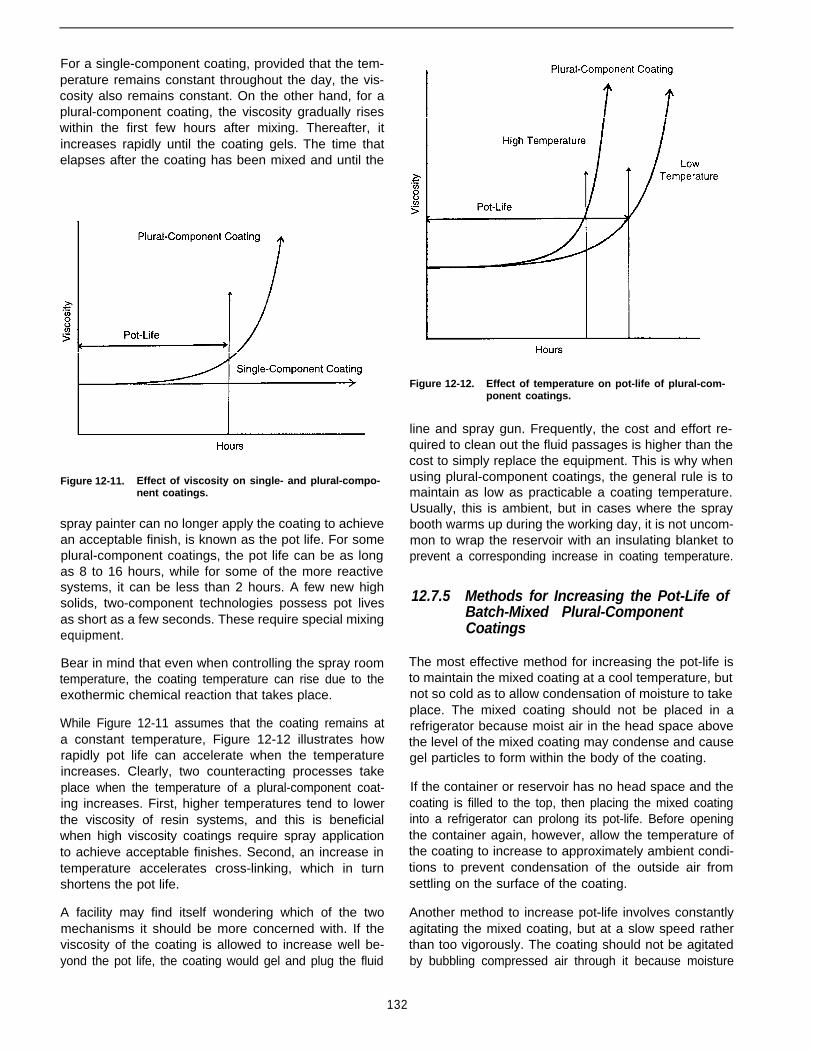
For a single-component coating, provided that the tem-perature remains constant throughout the day, the vis-cosity also remains constant. On the other hand, for aplural-component coating, the viscosity gradually riseswithin the first few hours after mixing. Thereafter, itincreases rapidly until the coating gels. The time thatelapses after the coating has been mixed and until the
Figure 12-11. Effect of viscosity on single- and plural-compo-nent coatings.
spray painter can no longer apply the coating to achievean acceptable finish, is known as the pot life. For someplural-component coatings, the pot life can be as longas 8 to 16 hours, while for some of the more reactivesystems, it can be less than 2 hours. A few new highsolids, two-component technologies possess pot livesas short as a few seconds. These require special mixingequipment.
Bear in mind that even when controlling the spray roomtemperature, the coating temperature can rise due to theexothermic chemical reaction that takes place.
While Figure 12-11 assumes that the coating remains ata constant temperature, Figure 12-12 illustrates howrapidly pot life can accelerate when the temperatureincreases. Clearly, two counteracting processes takeplace when the temperature of a plural-component coat-ing increases. First, higher temperatures tend to lowerthe viscosity of resin systems, and this is beneficialwhen high viscosity coatings require spray applicationto achieve acceptable finishes. Second, an increase intemperature accelerates cross-linking, which in turnshortens the pot life.
A facility may find itself wondering which of the twomechanisms it should be more concerned with. If theviscosity of the coating is allowed to increase well be-yond the pot life, the coating would gel and plug the fluid
Figure 12-12. Effect of temperature on pot-life of plural-com-ponent coatings.
line and spray gun. Frequently, the cost and effort re-quired to clean out the fluid passages is higher than thecost to simply replace the equipment. This is why whenusing plural-component coatings, the general rule is tomaintain as low as practicable a coating temperature.Usually, this is ambient, but in cases where the spraybooth warms up during the working day, it is not uncom-mon to wrap the reservoir with an insulating blanket toprevent a corresponding increase in coating temperature.
12.7.5 Methods for Increasing the Pot-Life ofBatch-Mixed Plural-ComponentCoatings
The most effective method for increasing the pot-life isto maintain the mixed coating at a cool temperature, butnot so cold as to allow condensation of moisture to takeplace. The mixed coating should not be placed in arefrigerator because moist air in the head space abovethe level of the mixed coating may condense and causegel particles to form within the body of the coating.
If the container or reservoir has no head space and thecoating is filled to the top, then placing the mixed coatinginto a refrigerator can prolong its pot-life. Before openingthe container again, however, allow the temperature ofthe coating to increase to approximately ambient condi-tions to prevent condensation of the outside air fromsettling on the surface of the coating.
Another method to increase pot-life involves constantlyagitating the mixed coating, but at a slow speed ratherthan too vigorously. The coating should not be agitatedby bubbling compressed air through it because moisture
132
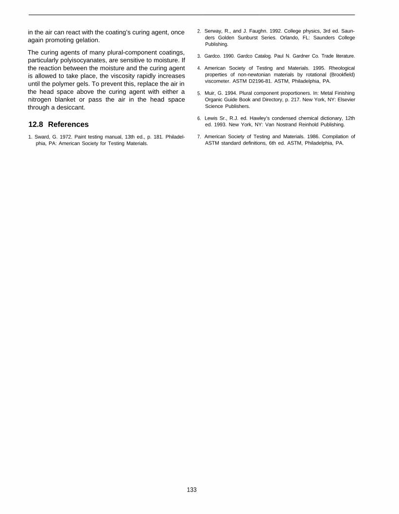
in the air can react with the coating’s curing agent, onceagain promoting gelation.
The curing agents of many plural-component coatings,particularly polyisocyanates, are sensitive to moisture. Ifthe reaction between the moisture and the curing agentis allowed to take place, the viscosity rapidly increasesuntil the polymer gels. To prevent this, replace the air inthe head space above the curing agent with either anitrogen blanket or pass the air in the head spacethrough a desiccant.
12.8 References
1. Sward, G. 1972. Paint testing manual, 13th ed., p. 181. Philadel-phia, PA: American Society for Testing Materials.
2.
3.
4.
5.
6.
7.
Serway, R., and J. Faughn. 1992. College physics, 3rd ed. Saun-ders Golden Sunburst Series. Orlando, FL: Saunders CollegePublishing.
Gardco. 1990. Gardco Catalog. Paul N. Gardner Co. Trade literature.
American Society of Testing and Materials. 1995. Rheologicalproperties of non-newtonian materials by rotational (Brookfield)viscometer. ASTM D2196-81. ASTM, Philadelphia, PA.
Muir, G. 1994. Plural component proportioners. In: Metal FinishingOrganic Guide Book and Directory, p. 217. New York, NY: ElsevierScience Publishers.
Lewis Sr., R.J. ed. Hawley’s condensed chemical dictionary, 12thed. 1993. New York, NY: Van Nostrand Reinhold Publishing.
American Society of Testing and Materials. 1986. Compilation ofASTM standard definitions, 6th ed. ASTM, Philadelphia, PA.
133
Chapter 13Minimizing Solvent Usage for Equipment Clean-Up
13.1 Introduction
13.1.1 Pollution Prevention Considerations
Solvents are used in various parts of a coating facility,including:
l Vapor degreasing
l Solvent wiping of substrates prior to painting
l Reducing paints and coatings to adjust viscosity
l Clean-up of spray equipment
Earlier chapters covered in depth the strategies for mini-mizing solvent use through different pretreatment fac-tors as well as application process factors. This chapterfocuses primarily on minimizing the use of solvents forthe clean-up of spray application equipment, and forother miscellaneous purposes.
Most facilities that use solvent-borne coatings find thattheir liquid hazardous waste comprises mainly the sol-vents they use to clean the fluid hoses, pressure pots,and spray guns. The solids content of liquid hazardouswaste from a paints and coatings facility is often as lowas 10 to 15 percent. This means that 85 to 90 percentof the liquid hazardous waste is a mixture of solvents.
Most state volatile organic compounds (VOCs) regula-tions require that solvents used for equipment clean-upmust be stored in closed containers. In addition, theregulations mandate that facilities clean the spray gunswithin an enclosed container. The purpose of theseprovisions is to minimize solvent evaporation duringequipment clean-up. As a consequence, the industrygenerates large volumes of spent solvent-paint mixturesthat are usually stored in 55-gallon drums.
Facilities can incorporate strategies for utilizing andminimizing waste solvent. The strategies that this chap-ter discusses are:
l Recycle solvents
l Minimize emissions of hazardous air pollutants(HAPS)
l Follow regulatory provisions
13.1.2 Decision-Making Criteria
Decision-making criteria relevant to minimizing solventusage for clean-up, as addressed in this chapter, arehighlighted in Table 13-1.
13.2 Solvent Recycling
A facility may use a solvent distillation unit to boil off thesolvents, and then condense them in a clean 5-gallonpail or 55-gallon drum. Figure 13-1 shows a typicaldistillation unit.
The distillation units that paint facilities use are usuallyexplosion-proof. They consist of a large permanent con-tainer with a tight-fitting cover. Heating coils surroundthe outside of the container. At the end of a shift, orwhenever appropriate, the painter pours or pumps themixture of waste solvent and paint into the container,closes the cover, and turns on the heating element. Asthe temperature rises, the most volatile solvents start toevaporate off into a long condensation coil. A refrigera-tion unit cools the coil, and as the solvents pass throughthe coil they condense into clean liquid solvent. A hoseat the end of the coil transfers the condensed solventinto a 5-gallon pail or 55-gallon drum. As the temperaturein the unit continues to climb, less volatile solvents startto evaporate and subsequently condense. This processcontinues until approximately 85 to 90 percent of thewaste solvent/paint mixture evaporates and condenses.
The sludge remaining at the bottom of the unit is a veryhigh concentration of the paint solids. Typically, this onlyaccounts for 10 to 15 percent of the original volume, andthis, together with the polyethylene bag that contains it,is disposed of as solid hazardous waste.
The facility can re-use the clean collected solvent as aclean-up solvent. Because the solvent mixture mightcontain a different blend of solvents from that used inthe formulation of the coatings, it is not common to usethe condensed solvent as a reducer for the coatings.One other approach is to sell the waste solvent to a solventblender or a facility that can use the solvents as fuel.
Solvent distillation units are available in all sizes, fromless than 5 gallons to 55 gallons. Names and addresses
134

Table 13-1. Decision-Making Criteria Regarding Minimizing Solvent Usage for Equipment Clean-Up
issue Considerations
Does the facility send largevolumes of solvent-borne paintsas well as reducing andclean-up solvents out as waste?
Are any of the solvents used inthe facility HAPS or ODCs?
Does the facility’s potential toemit solvents cause it to exceeda threshold for Title iii and/orTitle V?
Has the facility checked to see ifthe solvents it is using havehigh-boiling points?
Do the operators clean thespray guns and fluid hoses byatomizing solvent through thespray guns?
l If yes, consider installing a solvent distillation machine that would allow for the on-site recovery ofsolvents; first, however, fully investigate the hazardous waste regulations that concern on-sitesolvent recovery and recycling.
l If distilling on-site is not possible, consult with a solvent recycling company to see if it is worthhaving the company perform your recycling.
l If yes, consider finding alternatives because most solvent companies now offer solvent blendsthat have excellent solvency but contain neither HAPS nor ODCs; for some applications, you mayfind solvents that are not VOCs, HAPS, nor ODCs.
l If yes, find alternatives that would allow the facility not to exceed this threshold; the cost benefit tothe company is usually well worth the effort.
l If not, ensure this is done because it may be possible to substitute some of the more volatile(lower boiling) solvents with ones that have higher boiling points and evaporate more slowly.
l If yes, check local regulations because this is now an air pollution violation in many states.
l Consider flushing the hoses and guns by spraying a stream of solvent (not atomized) directly intoa 55-gallon hazardous waste drum, and immediately replacing the lid.
Figure 13-1. Typical solvent distillation unit (illustration cour-tesy of Siva, a division of Flair Environmental).
of vendors appear in the annual buyers’ guides that themajor coatings journals publish annually.
Joseph (1) has described the permitting requirementsand alternatives for dealing with solvent recyclers. Be-cause the issue is complex, readers should delve furtherinto the matter with their local state agencies or legal advi-sors before making a decision to install such equipment.
In the absence of a solvent distillation unit, a facility canreduce the cost of hazardous waste disposal by segre-gating the wastes. Water-borne paints, and any other
water-borne products, should not be mixed with thesolvent wastes. Papers, masking tape, waste cups,rags, etc., should also be segregated and not dumpedinto the solvent waste drums. While the overall volumeof waste remains the same, by segregating, the facilitycan minimize the volume of waste it needs to send to ahazardous waste disposal site. Some of the otherwastes might be able to go to a landfill. The potential costsreductions for such segregation are well worth the effort.
13.3 Minimizing Emissions of HazardousAir Pollutants
Title III of the Clean Air Act Amendments of 1990 (40CFR Part 63) lists solvents considered to be hazardousair pollutants (HAPS). The following list includes themost common HAP solvents found in paints and coat-ings formulations, as well as in clean-up solvents:
l Methylethylketone (MEK).
l Methylisobutylketone (MIBK).
l Toluene.
l Xylene(s).
l 1,1,1 Trichloroethane (also an ozone depleting com-pound, or ODC).
l Methylene chloride.
Title III lists many other solvents and chemicals used inpaints and coatings formulations but they generally ap-pear in smaller quantities. To determine whether a coat-ing formulation contains one of these HAPS or ODC’s,refer to the Material Safety Data Sheet (MSDS) that issubmitted with every delivery of paints and solvents.
135

While paints and coatings facilities can still use thesesolvents in the foreseeable future, stringent air qualityregulations encourage facilities to find substitutes. Ifsubstitutes are not possible, facilities must try to estab-lish measures for minimizing their emissions into the air.
Both Title III “Hazardous Air Pollutants” and Title V “Per-mit Operating Rule” (40 CFR Part 70) require a majorfacility to comply with their regulations. A major facilityis one that has the potential to emit more than 10 tonsper year (tpy) of any one HAP, or more than 25 tpy of acombination of HAPS, and some states may decide tolower these thresholds. Title V also considers a facilityto be major if its emissions of VOCs are more than100(tpy).
The definition of potential to emit is complex, so a facilityshould seek clarification from its local air pollutionagency. Even a facility that does not use large quantitiesof paints and solvents may have a potential to emit overthe threshold levels. Because the definition of “major”from above covers only some of the requirements fromTitles III and V, each company should refer to bothregulations to determine all of the criteria that mightaffect it. Both Basset (2) and The Air Pollution Consult-ant (3) provide excellent sources for understanding theimplications of these regulations.
13.3.1 Strategies To MinimizeHAP Emissions
13.3.1.1 Using Substitutes
Facilities that want to minimize their HAP emissions canask their coating vendors and solvent suppliers to usesubstitutes where such exist. Substitute solvents, how-ever, may affect the viscosity, drying time, and flow-outcharacteristics of the coatings. Substitute solvents usedfor clean-up of equipment may not be as efficient as theoriginal solvent blend. Therefore, tests must ensure thatthe compromises being made are acceptable to thepaint facility. If compromises are necessary, the facilityshould balance them against the difficulty of having tocomply with strict and possibly cumbersome Title III orTitle V regulations.
13.3.1.2 High-Boiling Solvents
High-boiling solvents evaporate slower than those with alower boiling point. Thus, if an operator is cleaning sprayequipment, he has a greater opportunity to capture dirtysolvent before it evaporates. Therefore, in formulating ablend for clean-up purposes, a facility should consider oneor more of the solvents listed in Table 13-2.
13.3.1.3 Example Blend: Ashland Chemicals
Ashland Chemicals has provided one blend of clean-upsolvent that has worked well for alkyds, epoxy, and
Table 13-2. High-Boiling Solvents (4, 5)
Solvent Type
Hydrocarbon Solvents:
Hi flash VM&P Naphtha
VM&P Naphtha
Mineral spirits
Odorless mineral spirits
Stoddard solvent
Aromatic Hydrocarbons:
Toluenea
Ethyl benzene
Alcohols:
lsobutyl alcohol
n-Butyl alcohol
Ketones:
Methylisobutylketone(MIBK)
Methyiisoamylketone(MIAK)
Boiling Range
OF OC
260 - 288 126 - 142
244 - 287 118 - 140
307 - 389 153 - 198
354 - 388 179 - 198
308 - 388 154 - 197
230 - 232 110 - 111
275 - 277 135 - 136
223 - 229 106 - 109
243 - 245 117 - 119
237 - 244 114 - 117
287 - 297 141 - 148
a On the EPA 33/50 list as a hazardous air pollutant.
polyurethane coatings, including chemical agent resis-tant coatings (CARC). The blend’s formulation follows:VM&P naphtha (40%) methanol (20%), acetone (15%),n-butyl acetate UG (15%) and isobutyl alcohol (10%).
Note that none of the solvents in the blend is either anHAP or an ODC. In addition, this formulation is notunique or proprietary to Ashland and can be formulatedby any solvent distributer.
13.4 Regulatory Provisions
State regulations regarding paints and coatings exist inthe interest of preventing pollution. These regulationsact as necessary and useful guides for facilities seekingto minimize the environmental impact of their solventusage for clean-up purposes. Surface coating regula-tions in several states have provisions similar to thosein California. The following example comes from Califor-nia’s South Coast Air Quality Management District rulefor the painting of metal parts and products.
13.4.1 South Coast Rule 1107, (b)(3-7)
A person shall not use VOC-containing materials for theclean-up of equipment used in coating operations unless:
l The VOC is collected in a container which is closedwhen not in use and is properly disposed of, suchthat the VOC is not emitted into the atmosphere; or
136
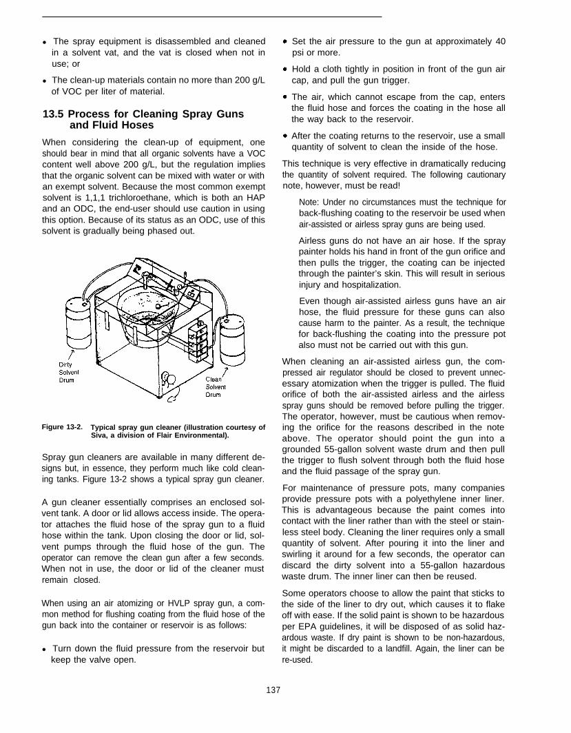
l The spray equipment is disassembled and cleanedin a solvent vat, and the vat is closed when not inuse; or
l The clean-up materials contain no more than 200 g/Lof VOC per liter of material.
13.5 Process for Cleaning Spray Gunsand Fluid Hoses
When considering the clean-up of equipment, oneshould bear in mind that all organic solvents have a VOCcontent well above 200 g/L, but the regulation impliesthat the organic solvent can be mixed with water or withan exempt solvent. Because the most common exemptsolvent is 1,1,1 trichloroethane, which is both an HAPand an ODC, the end-user should use caution in usingthis option. Because of its status as an ODC, use of thissolvent is gradually being phased out.
Figure 13-2. Typical spray gun cleaner (illustration courtesy ofSiva, a division of Flair Environmental).
Spray gun cleaners are available in many different de-signs but, in essence, they perform much like cold clean-ing tanks. Figure 13-2 shows a typical spray gun cleaner.
A gun cleaner essentially comprises an enclosed sol-vent tank. A door or lid allows access inside. The opera-tor attaches the fluid hose of the spray gun to a fluidhose within the tank. Upon closing the door or lid, sol-vent pumps through the fluid hose of the gun. Theoperator can remove the clean gun after a few seconds.When not in use, the door or lid of the cleaner mustremain closed.
When using an air atomizing or HVLP spray gun, a com-mon method for flushing coating from the fluid hose of thegun back into the container or reservoir is as follows:
l Turn down the fluid pressure from the reservoir butkeep the valve open.
Set the air pressure to the gun at approximately 40psi or more.
Hold a cloth tightly in position in front of the gun aircap, and pull the gun trigger.
The air, which cannot escape from the cap, entersthe fluid hose and forces the coating in the hose allthe way back to the reservoir.
After the coating returns to the reservoir, use a smallquantity of solvent to clean the inside of the hose.
This technique is very effective in dramatically reducingthe quantity of solvent required. The following cautionarynote, however, must be read!
Note: Under no circumstances must the technique forback-flushing coating to the reservoir be used whenair-assisted or airless spray guns are being used.
Airless guns do not have an air hose. If the spraypainter holds his hand in front of the gun orifice andthen pulls the trigger, the coating can be injectedthrough the painter’s skin. This will result in seriousinjury and hospitalization.
Even though air-assisted airless guns have an airhose, the fluid pressure for these guns can alsocause harm to the painter. As a result, the techniquefor back-flushing the coating into the pressure potalso must not be carried out with this gun.
When cleaning an air-assisted airless gun, the com-pressed air regulator should be closed to prevent unnec-essary atomization when the trigger is pulled. The fluidorifice of both the air-assisted airless and the airlessspray guns should be removed before pulling the trigger.The operator, however, must be cautious when remov-ing the orifice for the reasons described in the noteabove. The operator should point the gun into agrounded 55-gallon solvent waste drum and then pullthe trigger to flush solvent through both the fluid hoseand the fluid passage of the spray gun.
For maintenance of pressure pots, many companiesprovide pressure pots with a polyethylene inner liner.This is advantageous because the paint comes intocontact with the liner rather than with the steel or stain-less steel body. Cleaning the liner requires only a smallquantity of solvent. After pouring it into the liner andswirling it around for a few seconds, the operator candiscard the dirty solvent into a 55-gallon hazardouswaste drum. The inner liner can then be reused.
Some operators choose to allow the paint that sticks tothe side of the liner to dry out, which causes it to flakeoff with ease. If the solid paint is shown to be hazardousper EPA guidelines, it will be disposed of as solid haz-ardous waste. If dry paint is shown to be non-hazardous,it might be discarded to a landfill. Again, the liner can bere-used.
137
Regarding conventional air-atomizing, HVLP, and air-atomizing electrostatic guns, special spray gun hosecleaners are available from spray equipment manufac-turers. These force a mixture of air and solvent turbu-lently through the fluid hose. The turbulence is effectivein efficiently flushing the coating from the hose, whereasonly a small quantity of solvent is required. Some equip-ment vendors, however, have withdrawn their productsfrom the market because they felt that the turbulenceatomized the solvent which could not then be collectedfor reuse. The end-user must experiment to determinewhether or not such a device would minimize solventemissions into the air.
13.6 References
1.
2.
3.
4.
5.
Joseph, R. 1995. Dealing with solvent distillation of waste paintfilters. Metal Finishing 93:44.
Basset, S., ed. 1995. Complying with Clean Air Act regulations: Issuesand techniques. New York, NY: Elsevier Science Publishers.
The Air Pollution Consultant. (Bimonthly). New York, NY: ElsevierScience Publishers.
Ashland Chemical Co. No date. Solvent Property Chart. Colum-bus, OH. Trade literature.
Lide, D., ed. 1991/92. CRC handbook of physics and chemistry,72nd ed. Boca Raton, FL: CRC Press.
138
Chapter 14Paint Stripping: Alternatives to Solvent-Based Methods
14.1 Introduction
14. 1. 1 Pollution Prevention Considerations
Paint stripping is a process stage common to paints andcoatings operations. Although efficiently run operationsattempt to minimize the need for paint stripping, theneed can still arise for workpieces either because theapplied coating is defective, the job specifications havechanged, or the original coating has aged. Occasionally,process equipment (e.g., racks, vessels, booths, andgrates) also must undergo paint stripping to remove thebuildup of overspray.
Historically, operations relied extensively on chlorinatedsolvents (e.g., primarily containing methylene chloride)to remove coatings because formulations were inexpen-sive to use and their effectiveness well established.Reliance on such approaches has become more expen-sive, however, due to the cost of managing wastewatercontaminated with toxic chemicals and controlling therelease of volatile organic compounds (VOCs).
For a number of years, operators-especially in theautomotive and heavy equipment industries-also havebeen using aqueous paint stripping products where ap-propriate. These formulations generate less pollutionbecause they are based on a relatively small amount oforganic solvent, but they are effective on a-narrowerrange of coatings. The relatively new semi-aqueousproducts, formulated with water and a nonchlorinatedsolvent, await more extensive use in industrial opera-tions to demonstrate apparent advantages (e.g., pollu-tion reduction and effectiveness on resistant coatings).
In the meantime, an array of alternative approachesinvolving “cleaner” technologies are gaining wider usein paint stripping operations. These methods are consid-ered cleaner because they rely on physical mechanismsof action for coating removal rather than chemical sol-vents. As a result, when used in appropriate industrialapplications, these approaches can help operators mini-mize pollution generation, and thereby hold down asso-ciated process costs.
Although these newer approaches offer important pollu-tion prevention opportunities, the broad application of
any single method is unlikely. That is, rather than onecoating removal technology replacing solvent strippersin all applications, operators will need to assess tech-nologies on a process-specific basis. The appropriate-ness of a technology for a particular facility will dependon factors that include the type of coatings to be re-moved and the nature of the workpieces’ substrate.
Alternative technologies are discussed in this chapter inthe context of pollution prevention and process effi-ciency considerations.
14.1.2 Decision-Making Criteria
Decision-making criteria relevant to the use of alterna-tive paint stripping approaches, as addressed in thischapter, are highlighted in Table 14-1.
14.2 Process Basics
Paint stripping operations generally are conducted whena previously applied coating on a substrate must beremoved. Usually paint is stripped from workpieces inpreparation for recoating. In some cases, however, met-al workpieces and parts undergo surface polishing in-stead of painting (e.g., polished aluminum used forsome components in aircraft); thus, when appropriate,one pollution prevention approach is to avoid the needto apply a coating in the first place.
Paint stripping is a stage in most paints and coatingsprocesses even at facilities where best managementpractices are closely adhered to throughout the opera-tion. This process step may be necessary for any of thefollowing reasons:
l Defects are detected in the finished piece.
l Specifications change after finishing (e.g., color, per-formance requirements).
l A workpiece’s original coating has aged.
l Paint has built up on production line equipment fromoverspray (e.g., conveyor hooks and racks, spraybooth grates).
The decision whether to rework or scrap workpieces callsfor assessing the value of the particular piece in regard to
139

Table 14-1. Decision-Making Criteria Regarding Paint Stripping Operations
Issue Considerations
Are workpieces currently being stripped using a methylenechloride product?
Are the workpieces high-cost items with high-performancespecifications (e.g., aircraft components), requiring that criticaltolerances not be altered by processing?
l If so, consider the appropriateness of switching to “cleaner” paintstripping technologies that generate less pollution.
l If so and the workpieces cannot be subjected to extensive contactwith water, consider plastic media blasting, wheat starch blasting, orcarbon dioxide pellet cryogenic blasting.
l If so and the workpieces can be subjected to contact with water,consider high- or medium pressure water blasting or sodiumbicarbonate wet blasting.
Must paint coatings be stripped from workpieces selectively (e.g., l If so, consider wheat starch blasting, sodium bicarbonate wet blasting,remove only the topcoat) or removed from delicate substrates? high-pressure water blasting, or carbon dioxide pellet cryogenic blasting.
Are the workpieces assemblies that include machined surfaces l If so, consider carbon dioxide pellet cryogenic blasting.and moving parts, and thus cannot be subjected to extensivecontact with water or to a small media that can becomeentrapped by components?
Are the items to be stripped process-related equipment (hooks, l If so, consider medium-pressure water blasting, burnoff, molten saltgrates, baskets) coated with overspray? bath stripping, or liquid nitrogen cryogenic blasting.
the number of pieces in the lot and the cost of reprocess-ing. For all but the simplest and cheapest items, reworkingusually proves more cost effective than disposal.
As discussed in this chapter, paint stripping can beconducted by various means. The conventional ap-proach involves the application of a chemical solvent.Traditional formulations are based on methylene chlo-ride (60 to 65 percent), which penetrates the coatingcausing it to swell and separate from the substrate. Thisapproach, however, generates organic vapors, whichraise concerns about threats to worker health and aboutdamage to the ozone layer of the atmosphere, as wellas considerable sludge and wastewater laden with sol-vent. Aqueous and semi-aqueous paint stripping formu-lations, with smaller percentages of chemical content,also are available. Although, these less-concentratedchemical formulations minimize pollution concerns,drawbacks can include high cost, limited applicability,and slower and less-thorough performance.
As a result, industry and government have been con-ducting extensive research into the development ofpaint stripping methods whose performance relies lesson solvents. Alternative approaches under developmentor already in use involve on one or more of the followinggeneral mechanisms of action:
Impaction. Breaking up the coating by subjecting theworkpiece surface to a flow of grit material (media)delivered at high velocity.
Abrasion. Wearing away the coating by scouring theworkpiece surface with a rough material; some mediadelivered at high velocity have a scouring effect.
Thermodynamics. Oxidizing, pyrolizing, and/or vapor-izing the coating by subjecting the workpiece to heat.
Cryogenics. Releasing the bond between the coatingand the substrate by subjecting the workpiece to ex-
140
treme cold, making the coating friable and inducingdifferential contraction.
One abrasion approach, media blasting, is also used toclean corrosion and other contaminants from uncoatedmetal workpieces before applying a primer-topcoatsystem, as discussed in Chapter 8 (on abrasive blastcleaning).
The various alternative approaches discussed in thischapter are considered “cleaner” in terms of pollutiongeneration because their performance is based onphysical mechanisms rather than solvents. These ap-proaches also have their drawbacks. The informationprovided is intended as a brief introduction to eachtechnology; for more detailed information, see EPA’sGuide to Cleaner Technologies: Organic Coating Re-moval and EPA’s Reducing Risk in Paint Stripping: Pro-ceedings of an International Conference (References 1and 2, respectively).
Before adopting an alternative paint stripping approach,the facility operator must fully consider the associatedtradeoffs in respect to the specific paints and coatingsoperation. Factors to consider include:
l Workpiece characteristics (e.g., size, substrate)
l Coating composition
l Surface specifications for the stripped substrate
l Processing rate
l Facility space and process compatibility considerations
1 The material presented in this chapter draws extensively from bothof these EPA documents. Information is also available on the In-ternet; see, for example, the U.S. department of Defense’s libraryhome page (http://clean.rti.org/larry/nav-in.html) or EPA’s Envi-rosense home page (http://es.inel.gov). Detailed information on par-ticular approaches also may be available from industry groups andtrade associations.
l Pollution/waste generation
l Costs (i.e., capitol and operating)
14.3 Solvent-Based, Aqueous, andSemi-aqueous Methods
As described in this section, three conventional ap-proaches to paint stripping involve the use of chemicalsolvents in varying amounts. Given the increasing costand regulatory constraints associated with traditionalsolvent-based approaches, more facility operators areassessing expanded application of aqueous methodsand examining the potential advantages of semi-aque-ous products. This discussion briefly considers thesethree methods of coating removal. The section that fol-lows reviews a selection of more recently developedapproaches that place particular emphasis on pollutionprevention-the so-called cleaner technologies.
14.3.1 Solvent-Based Methods
Most paint stripping is conducted by immersing or spray-ing workpieces with an organic solvent-based formula-tion. The solvent penetrates the coating and underminesits bond with the substrate, as indicated by wrinkling,bubbling, and blistering on the surface of the piece. Thesoftened coating and solvent sludge are then wiped,scraped, or flushed away from the substrate. Often aworkpiece must undergo this process step several timesbefore the coating is completely removed. After coatingremoval, the piece usually undergoes a water rinse.
In general, solvent is only sprayed on workpieces if theyare too large for immersion or if they are assemblies withsophisticated components that could be damaged byextensive contact with the solvent. If only very specificareas of an assembly need to be reworked, then thesolvent may be wiped onto the appropriate surfaces.Additionally, if only a small number of pieces need to bereworked, spraying might present a more cost-effectiveapproach than installing an immersion stripping line.
The most widely used paint stripping products are for-mulated with methylene chloride (also known as dichlo-romethane [DCM]). Although these chlorinated solventsare effective, versatile, and relatively economical, theiruse results in the release of VOCs, which are becomingthe focus of increasing regulation under the Clean AirAct Amendments. In particular, EPA has identified paintstripping operations as a hazardous air pollutant (HAP)source category. As a result, such operations mighteventually be required to implement Maximum Achiev-able Control Technology.
Additionally, solvent-based methods generate sludgeand wastewater that contain toxic chemicals. Disposalprocedures required under the Resource Conservationand Recovery Act (RCRA) and recordkeeping require-
ments under Section 313 of Title III can increase the costof managing such wastes.
Nonchlorinated solvents represent another broad cate-gory of paint stripping products. These solvents, whichare based on such diverse chemicals as N-methyl py-rollidone, various glycols or glycol esters, and dimethylsulfoxide, are used almost exclusively in immersionpaint stripping operations. Although these solvents allowfacility operators to avoid concerns about VOCs andminimize the generation of sludge with toxic constitu-ents, nonhalogenated products tend to be considerablymore expensive than methylene chloride formulations.Additionally, immersion baths of nonhalogenated sol-vents must be heated (from 140o to 250°F) to speed uptheir performance capabilities, which adds to opera-tional costs. Even when heated, however, nonhalogen-ated solvents have a somewhat selective chemicalaction and thus tend to be used in a narrower range ofapplications than methylene chloride solvents.
141
14.3.2 Aqueous Methods
Stripping paint with aqueous products is a well-estab-lished methods for use in industrial operations process-ing metal workpieces. Although aqueous products arewater based, formulations generally include someamount of an organic solvent. The most widely usedaqueous strippers have a caustic component. A typicalformulation might include water, 10 to 20 percent sodiumhydroxide, up to 20 percent organic solvent, substantialamounts of surfactants (which are caustic, stable, sur-face-active agents), and a chelating agent.
Caustic aqueous strippers are primarily used in immer-sion processes. Immersion baths are heated (from 180-to 240°F) to accelerate the performance of the activeagents in such formulations. In most operations, immer-sion is followed by a water rinse step.
Historically this type of aqueous paint stripper waswidely used in the automotive and heavy equipmentindustries. The use of aqueous products in these indus-tries has declined over the years, however, as moreresistant coatings have been introduced. Aqueous strip-pers are still used in many operations that process homeappliances and are used generally to clean processequipment. Formulations that include sulfuric or chromicacid also are in use, but for more selective applications.
As with nonchlorinated solvents, because aqueous for-mulations must be heated to enhance their perform-ance, using them can add to operating costs. Also,although they minimize pollution generation issues,aqueous products are effective on a limited range ofcoatings and can be used only on ferrous metal andmagnesium substrates.

14.3.3 Semi-aqueous Methods
Semi-aqueous products, which include water and a non-chlorinated solvent in roughly equal amounts, are rela-tively new and thus not yet in wide use. Such productsare attracting considerable interest, however, based onindications that they are effective for stripping even themost resistant aircraft and aerospace paints. Anotherattraction is that they can be used in both spray andimmersion process lines. Also, sludge and wastewatergenerated by this approach are considered relativelyeasy to manage because they are generally free of toxiccomponents (e.g., chrome, phenol).
Drawbacks of this approach include the higher cost ofsemi-aqueous products and the longer time required toachieve desirable performance.
14.4 “Cleaner” Technologies: Alternativesto Conventional Methods
This section briefly describes a selection of alternativepaint stripping approaches and lists their respective ad-vantages and potential drawbacks. Approaches are pre-sented according to their mechanism of action. It isunlikely that any one of these approaches will offer abroadly applicable means of stripping coatings in indus-trial processes. Nonetheless, facility operators shouldconsider such cleaner technologies when developing astrategy for minimizing pollution generation. A numberof newer approaches not covered in this document alsoshow promise for reducing process-related pollution inpaint stripping operations. Certain of these emergingtechnologies in particular are promising and thus bearwatching, including laser heating, flashlamp heating,and ice crystal blasting. (For information on these meth-ods, see Refs. 1 and 2.)
14.4.1 Impaction Methods
14.4.1.1 Plastic Media Blasting
Plastic media blasting (PMB) is an impaction methodthat is capable of removing a coating without damagingthe substrate of a delicate workpiece. The approachinvolves projecting plastic media at a workpiece’s sur-face either pneumatically with a hose-and-nozzle sys-tem (usually in manual operations) or centrifugally fromrotating wheels (in automated operations within a cabi-net). After the coating has been removed, the workpieceis vacuumed or subjected to high-pressure air to removeresidual plastic dust. Because PMB is a completely dryprocess that relies on a nontoxic media to remove coat-ings, no wastewater or VOCs are generated.
In most applications, the plastic media are collected andcleaned, using an air cyclone or vibrating screens, andthen reused several times before being discarded. De-pending on the particular coating being removed, how-
ever, debris cleaned from the media may contain haz-ardous metals or unreacted resins that require specialhandling. In general, spent media are not recyclable orbiodegradable, although research is being conducted onbeneficial approaches to managing spent media.
The PMB approach has been widely used in both themilitary and commercial sectors. While PMB is suffi-ciently sensitive to selectively remove individual coatinglayers, with larger and harder media this approach alsocan be used to remove such resistant finishes as poly-urethane and epoxy coatings. The PMB method is ap-plicable for metal substrates as well as plastic surfaces.PMB is used in the aerospace industry to remove coat-ings without damaging sensitive underlying substrates(e.g., the aluminum skins of aircraft).
Key advantages of the PMB approach include:
Minimizes pollution generation. Avoids generation ofwastewater and VOCs.
Recyclability If the correct plastic media is selected,they can be recycled up to 30 times.
High throughput. Can be effective at a higher coatingremoval rate than is possible using some solvents.
Broad applicability For example, it can be used onsteel, aluminum, plastic, fiberglass, glass, printed cir-cuit boards, and aluminum clad materials.
Sensitivity Avoids damaging substrates or alteringthe dimensions of critical components; can removeindividual coatings.
Limited masking required. Less than for other con-ventional stripping processes, such as chemical strip-ping or sand blasting.
Principal limitations of the PMB approach include:
Conventional sand or grit blasting can be faster.
Less effective than other methods for cleaning proc-ess equipment with a heavy buildup of coatings.
Less effective than other methods for removing rustand corrosion from metals.
Larger and harder media can damage plastic andcomposite substrates.
Contaminants remaining in the recycled media candamage substrates.
Capital and startup costs can be higher than for con-ventional abrasive blasting.
14.4.1.2 Wheat Starch Blasting
Wheat starch blasting is an impaction method that in-volves use of generally the same techniques and proc-ess equipment as PMB. The principal distinctionbetween these two methods is the blast media: Wheat
142

starch is even more gentle than plastic. Additionally,because wheat starch is 100 percent carbohydrate, thespent media is biodegradable. Using aerobic wastemanagement processes, the media can be digested intoa liquid that can then be separated from the coatingdebris. Also, wheat starch is a renewable agriculturalresource that, for certain applications, can be used ef-fectively in place of petroleum-based media.
Although wheat starch is relatively soft, it can be recy-cled several times before the particles become too smallto be effective. As the media breaks down, dust-likeparticles must be stripped from coarser particles in therecycling process.
Wheat starch blasting is of interest primarily for its gentlestripping action. Thus, application and testing of thismethod have been focused on sensitive substrates,such as thin aluminum (e.g., in the aircraft industry) andfiberglass and certain plastics (e.g., in the automotiveindustry).
Key advantages of the wheat starch blasting approachinclude:
Sensitivity Avoids damaging substrates; recom-mended particularly for substrates such as aluminum,soft alloys, anodized surfaces, and composites.
Selectivity. Individual coatings can be removed (e.g.,only the topcoat).
Minimizes pollution generation. Avoids generation ofVOCs and excess wastewater.
Recyclability If the correct plastic media is selected,they can be recycled up to 30 times.
Moderate throughput. Can be effective at a moderatecoating removal rate.
Low-cost, biodegradable media. Wheat starch is aninexpensive, renewable resource; spent media canbe biodegraded from sludge.
Principal limitations of the wheat starch blasting ap-proach include:
Stripping action can be slow, depending on coatinghardness.
Media are sensitive to moisture and can require theaddition of an air drying system in humid environ-ments.
Removal of the media dust and paint chips requiresa somewhat extensive media recovery system.
Dust generation can present an explosion potentialunless precautions are taken.
May not be appropriate for workpieces that are as-semblies because media particles can become en-trapped.
Less effective than other methods for cleaning proc-ess equipment because of the heavy buildup of coat-ings.
Less effective than other methods for removing rustand corrosion from metals.
Contaminants remaining in the recycled media candamage substrates.
14.4.1.3 High- and Medium-Pressure WaterBlasting
Water blasting is a well-established impaction methodfor high-throughput surface cleaning that has emergingapplications for coating removal processes. This blast-ing approach involves subjecting workpieces to jets ofwater delivered at sufficient pressure from rotating noz-zles to strip surface material without the benefit of anabrasive media. For high-pressure blasting operations,water is pumped at a rate ranging from 15,000 to 30,000psi. Medium-pressure blasting is performed with waterjets operating in the range of 3,000 to 15,000 psi.
This blasting approach generally avoids the generationof VOCs and other air quality issues associated withsome wet blasting media. For some operations, how-ever, workpieces first undergo a presoak with alcohol ora similar inorganic solvent. Water used in blasting op-erations can be recycled after if has been processed toremove debris.
In the automotive industry, medium-pressure waterblasting is used for stripping overspray coatings frompart support hooks used in water wall spray paintbooths. Also, a German airline has used this approachwith presoaking to strip aged coatings from planes.High-pressure water blasting is being developed by theU.S. Air Force for paint stripping operations on largeaircraft. (Ultra high-pressure water blasting-from30,000 to 50,000 psi-reportedly has been used selec-tively to remove resistant coatings in the automotive,aircraft, ship building, and nuclear industries [2].)
Key advantages of the water blasting approach include:
143
High throughput. Can yield a high rate of coatingremoval.
Minimizes pollution generation. Avoids generation ofVOCs, dust, and spent media; wastewater can betreated in a conventional treatment system.
Recyclability Water can be recycled after filtering outdebris.
Low cost. Medium-pressure operations can have lowcapital and operating costs.
Broad size applicability. No workpiece size restric-tions unless blasting cabinets are used; the process
can be used indoors or outdoors and in mobile op-erations.
Principal limitations of the water blasting approach in-clude:
l Capital costs can be high if sophisticated systemsare used (i.e., high-pressure systems would typicallyinvolve the use of robots).
l High volumes of water are necessary.
l A filtration system is required to recycle blasting water.
l Pressurized water jets can present a hazard to workers.
14.4.2 Abrasion Method
14.4.2.1 Sodium Bicarbonate Wet Blasting
Sodium bicarbonate wet blasting is an abrasion methodthat is similar in many respects to wheat starch blasting.The principal distinction is that the especially fine mediaused for this method (baking soda) scours the surface,rather than breaking up the coating by impaction. As withwheat starch blasting, this method is sufficiently gentleto remove coatings without damaging the substrate.
The media is delivered to the workpiece from a nozzlegenerally at low pressure with a wet blast system (i.e.,in water at from 20 to 70 psi, although the system candeliver the media at up to 500 psi). As with other wetblasting approaches, the use of water avoids possibledamage to the substrate from heat buildup and helpscontrol dust generated by shattering of the media. Typi-cally, a water rinse step follows the blasting step. Al-though the media cannot be recycled, they can bedissolved, leaving the coating debris to be filtered out fordisposal.
Coatings can be removed by this method using modifiedsandblasting equipment. If the process is operated in-doors, an exhaust ventilation system with a cycloneseparator and intake piping must be added to controlblast media overspray.
Sodium bicarbonate wet blasting has been used to re-move both friable and elastomer organic coatings onsensitive workpieces, such as thin metal parts and ma-chinery. This method is effective on both metal, plastics,and wood.
Key advantages of the sodium bicarbonate wet blastingapproach include:
l Sensitivity. Avoids damaging substrates; recommendedparticularly for thin metals (e.g., aluminum, anodized air-craft skins), plastics and composites, and wood: in par-ticular, heat sensitive substrates can be stripped becausethe blast water keeps the surface cool.
l Selectivity. Individual coatings can be removed (e.g.,only the topcoat).
l Minimizes pollution generation. Avoids generation ofVOCs and excess wastewater.
l Process efficiency Because the media are not recy-cled, the workpiece does not need to be cleaned priorto blasting.
l Moderate throughput. Can be effective at a moderatecoating removal rate.
l Low-cost media. Sodium bicarbonate is inexpensive;spent media can be dissolved from sludge.
Principal limitations of the sodium bicarbonate wet blast-ing approach include:
l The media cannot be recycled.
l Operator safety measures and equipment must beincluded in the process (e.g., an exhaust ventilationsystem).
l Uninhibited sodium bicarbonate and water residuecan corrode substrate.
l May not be appropriate for areas where water is inshort supply.
14.4.3 Thermal Methods
14.4.3.1 Burnoff
Burnoff is a thermal method that involves a combinationof volatilization, pyrolysis, and oxidation. This method ofpaint stripping is both fast and especially effective forresistant or accumulated coatings. Coating burnoff canbe achieved using one of three methods, each of whichrequires subjecting workpieces to extremely high tem-peratures.
In direct burnoff, workpieces are passed through anoven in which high-temperature flue gas (1,000” to1,200oF) ignites the coating. Workpieces then might besubjected to an afterburner step before undergoing astep for removing inorganic residues. Another burnoffapproach involves direct heating in an abrasive fluidizedbed, where the coating is thermally degraded throughpyrolysis and partial oxidation at a temperature of 900o
to 950°F. This approach requires the use of an after-burner to oxidize the intermediate organic products. Thethird approach relies on pyrolysis to volatilize the coat-ing. The organic fumes generated by this process aretreated in an afterburner, which converts hydrocarbonsto carbon dioxide and water. Workpieces must thenundergo a step for removal of inorganic residues. In theburnoff coating removal process, afterburners are gen-erally capable of minimizing the generation of VOCs.
Other than monitoring, operation of a burnoff coatingremoval line involves mechanical or manual loading ofworkpieces. Systems are typically automated, however.
144

Burnoff is widely used to strip thick overspray buildupfrom a variety of process equipment used in paints andcoatings operations. Burnoff technology may be usefulfor removing coatings from workpieces in certain opera-tions, but limitations apply. For example, metals with amelting point below 900-F generally are not appropriatefor this approach.
Key advantages of the burnoff approach include:
Performance. Effective for rapid removal of heavy,resistant coating deposits.
Minimizes pollution generation. Avoids generation ofVOCs and excess wastewater.
Applicable for a wide range of part sizes. Applicableto all shapes; limitations relate only to the size of theburnoff unit.
Principal limitations of the burnoff approach include:
l Temperatures are too high for parts made of plastics,composites, or metals -with relatively low meltingpoints (e.g., zinc-bearing materials).
Coatings that contain chlorinated compounds canemit hydrochloric acid; when part surfaces cool, hy-drochloric acid together with atmospheric moisturecan cause severe corrosion.
Products of incomplete combustion containing heavymetals or other compounds may be generated, re-quiring disposal as a hazardous waste.
Resulting gases can present risk of fire.
Abatement equipment (e.g., scrubbers or filters) maybe required for offgas treatment.
14.4.3.2 Molten Salt Bath Stripping
Molten salt bath stripping is a process that, like burnoff,is currently used primarily for fast removal of heavycoating deposits from process equipment used in paintsand coatings operations. The molten salt process in-volves immersing parts (either in baskets or suspendedfrom hooks) into a heated bath (from 550o to 900°F)containing inorganic salts (e.g., sodium carbonate). Thesalt functions as a heat transfer medium, subjectingimmersed parts to uniformly high temperatures that re-sult in chemical oxidation of the coating. Carbon andhydrogen in the coating are oxidized to carbon dioxideand water. The exothermic reaction that occurs in themolten salt bath minimizes the loss of heat that mightotherwise result from the immersion of cool parts. Ingeneral, metals from the coating pigments are retainedin the molten salt bath, entering the offgas only in smallamounts.
After the reaction has ceased, parts are removed fromthe bath and allowed to cool. A thin coating of salt willhave formed on part surfaces and must be removed.
This is accomplished by rinsing the parts in a tap waterbath at ambient temperature.
Along with sludge containing primarily metal salts, theprocess generates offgases and wastewater from therinsing step. Thus, operators must make provisions forsludge disposal and include offgas abatement equip-ment and wastewater treatment in their process line.
Molten salt bath stripping is used primarily for supportsand fixtures used in coating application lines. The ap-proach is relatively fast (bath dwell times range fromseconds to minutes) and particularly effective on heavy,resistant coatings. It can be used to remove a variety oforganic coatings, including nylon, polyester, and epoxies.
Key advantages of the burnoff approach include:
l Performance. Effective for rapid removal of heavy,resistant coating deposits.
l Pollution prevention. No VOCs (or odors) are gener-ated.
l Applicable for a wide range of part sizes. Applicableto all shapes; limitations relate only to the size of thebath.
l Not time-critical. If the metal substrate can withstandimmersion in the molten bath, the substrate will notbe harmed by overexposure (e.g., applies to moststeels and to aluminum).
l Long bath life. Sludge must be removed, but the bathitself does not need to be dumped and replenished.
l Minimal treatment required for waste rinse water. Af-ter making minor pH adjustments with a mineral acid,rinse water can be discharged; alternatively, becauseof its high pH, the water can be used beneficially toneutralize wastewater from other acidic operations(e.g., from an acid pickling or phosphating process).
Principal limitations of the molten salt bath approachinclude:
Generated sludge must be disposed of and rinsewastewater treated.
Abatement equipment (e.g., scrubbers or filters) isrequired for offgas treatment.
Temperatures are too high for parts made of plastics,composites, or metals with relatively low meltingpoints (e.g., some die-cast alloys).
Not appropriate for parts with sealed tubing becauseinternal pressure buildup can cause tube or weldfailures and pose a threat of explosion.
Operator safety measures and equipment must beincluded in the process (e.g., a fume hood must beinstalled to remove smoke generated by the process).
145
14.4.4 Cryogenic Methods
14.4.4.1 Carbon Dioxide Pellet Blasting
Carbon dioxide (CO,) pellet blasting is a cryogenicmethod capable of removing coatings from specifiedareas of a workpiece while minimizing the amount ofresidue left on the piece’s surface. The approach in-volves projecting dry ice pellets at a workpiece’s surface(at from 75 to 1,000 ft/sec) from a nozzle. (A centrifugalprojection system is in development.)
The equipment for this technology includes a system forconverting refrigerated liquid CO2 into the pelletizedblasting media. The media remove coatings by a com-bination of impact, embrittlement, thermal contraction,and gas expansion. After the pellets strike the workpiecesurface, they revert to a gaseous state, both enhancingcoating removal and avoiding significant residuebuildup. After blasting, workpieces are subjected to jetsof air to remove coating fragments.
Because the approach can strip coatings selectively(i.e., specific areas of a workpiece as well as individualcoating layers), it has broad application for industriesprocessing sophisticated parts and components. Appli-cations include the aerospace, automotive, electronics,and food processing industries. For example, thismethod can be used on surfaces near moving parts andon sensitive electronic pieces.
Key advantages of the CO2 pellet cryogenic blastingapproach include:
Selectivity/sensitivity. Can be used on specific areasof a workpiece and to remove individual coatings.
Process efficiency Minimizes residue on workpiecesurfaces. Also, the need for masking is either elimi-nated or reduced to a minimum.
Pollution prevention. Generates only small amountsof solid waste; also avoids handling of spent mediaand wastewater.
Broad applicability Can be used on a variety of sub-strates (e.g., steel, aluminum, printed circuit boards,fiberglass, plastics).
Minimized hazards. Uses a nonflammable, noncon-ductive blast media.
Principal limitations of the CO2 pellet cryogenic blastingapproach include:
l Media cannot be recycled.
l Process equipment is relatively expensive.
l Throughput can be slow for workpieces with resistantcoatings.
l Condensation can occur on the workpiece surface.
l Safety equipment must be included in the process(e.g., a ventilation system for CO2 gas).
14.4.4.2 Liquid Nitrogen Blasting
Liquid nitrogen cryogenic blasting is a variation of thePMB method that involves chilling the workpiece toembrittle the coating before subjecting it to impactionwith a plastic media. The piece is sprayed with liquidnitrogen as it rotates on a spindle within a cabinet, andthen is blasted with the impaction media, which areprojected into the cabinet by throw wheels.
After chilling the coating (to about -32OoF), the liquidnitrogen warms to ambient temperatures and evapo-rates into a gaseous form. This harmless gas can bevented to the atmosphere, leaving the media to becollected, separated from coating debris, and recycled.
The liquid nitrogen cryogenic blasting approach is usedprimarily to remove coating buildup from certain typesof process equipment used in paints and coatings op-erations (e.g., paint hangers, coating racks, floor grat-ings). Operations in the automotive and applianceindustries have used this method with success.
Key advantages of the liquid nitrogen cryogenic blastingapproach include:
Minimizes pollution generation. Avoids generation ofwastewater and VOCs; because the process is dry,no water is used.
Recyclability If the correct plastic media is selected,they can be recycled numerous times.
High throughput. Can be effective at a relatively highcoating removal rate.
Low operating costs. Compressed air and electricityrequirements are low.
Principal limitations of the liquid nitrogen cryogenicblasting approach include:
l Capital and startup costs can be high.
l Not appropriate for thin coatings and less effectiveon epoxies and urethanes.
l The stripping cabinet restricts the size of parts thatcan be processed.
14.5 References
1. U.S. Environmental Protection Agency. 1993. Guide to CleanerTechnologies: Organic Coating Removal. EPA/625/R-93/015. Of-fice of Research and Development, Cincinnati, OH (November).
2. U.S. Environmental Protection Agency. 1991. Reducing Risk inPaint Stripping: Proceeding of an International Conference. Wash-ington, DC, February 12-13. NTIS PB91-224-303. Office of ToxicSubstances, Washington, DC.
146

Chapter 15Minimizing Pollution in Spray Booths
15.1 Introduction
15.1.1 Pollution Prevention Considerations
Almost every paint facility that applies coatings by sprayhas at least one spray booth on the premises. Thischapter describes the most common booths. By ma-nipulating inefficient spray booth parameters, facilitiescan minimize rejects and reworks, thus lowering allforms of pollution.
Efficient operation of nearly all spray booths requiresthat they capture and retain paint particulates usingeither dry filters or water. Thereafter, facilities must dis-pose of the medium (filters or water) together with theoverspray. In large facilities, disposal can be a majorproblem because waste is so voluminous. Moreover,disposing of these large quantities can be costly.
Unfortunately, most companies purchase their dry filterson the basis of price rather than efficiency and holdingcapacity. This chapter offers guidelines for selecting themost appropriate filters. Alternately, water-wash spraybooths require chemicals to detackify or “kill” the paintoverspray. Because selecting the most appropriatechemical(s) is more complex than simply choosing ahighly alkaline hydroxide, the chapter also offers advicefor making this choice properly.
Beyond these most basic decisions, recognizing andaltering the other factors that contribute to rejects andreworks allows facilities to minimize pollution and maxi-mize efficiency. Transfer efficiency of a spray applicationis very sensitive to booth conditions, particularly air flow.Moreover, many coating defects result from poor boothdesign, poor booth maintenance, improper air flow, highbooth humidity, and other factors. Rework of large ma-chines can require major repaints, which result in theunnecessary use of coatings. This of course leads tomore air, water, and waste pollution, as well as higheroverall finishing costs.
The primary purpose of this chapter is to provide abackground concerning spray booths, and to outlinestrategies for minimizing reworks that result from spraybooth parameters. As most previous chapters have
explained, a reduction in rework automatically lowers allforms of pollution and improves the bottom line.
15.1.2 Decision-Making Criteria
Decision-making criteria relevant to minimizing pollutionin spray booths, as addressed in this chapter, are high-lighted in Table 15-1.
15.2 Definition and Function of Spray Booths
A spray booth is an enclosure that directs overspray andsolvent emissions from painting operations away fromthe paint operator and toward an entrainment section.Note that a spray booth is an abatement device forparticulates It is not an abatement device for volatileorganic compounds (VOCs). One can assume that allconventional spray booths emit all of the coatings’ VOCsthrough the stack of the booth or from the booth open-ings. The spray booth primarily exists to protect the spraypainters and other employees from exposure to potentiallytoxic vapors and particulates.
High concentrations of flammable solvent vapors alwaysconstitute a fire hazard, particularly in facilities withwelding and other spark-producing operations. Thus,another function of the spray booth is to prevent fireswithin a facility. Without spray booths, the risk of collect-ing a high concentration of flammable vapors in a facilityis high. Booths quickly and efficiently exhaust the vaporsto the atmosphere where the outside air dilutes them sothey no longer cause concern for a fire.
Some researchers have tried to determine whether VOCemissions can be concentrated by recycling the VOC-laden air back to the booth and then bleeding only aportion of it off to the outside. One of the industry’sprimary concerns is that this process can expose spraypainters to high concentrations of VOCs, although thiscan be mitigated by providing the painters with fully airconditioned suits so that they breath only outside cleanair. In fact, experimental work is now taking place at aMarine Corps base in Barstow, California, to furtherexplore this concept. Ayer (1) has already shown thatrecycling the air and bleeding off only a small fraction,which a thermal oxidizer or carbon adsorber will thenabate, is both cost-effective and environmentally sound.
147

Table 15-1. Decision-Making Criteria Regarding Minimizing Pollution in Spray Booths
Issue Considerations
Are the workpieces generally small and are theysuspended from a conveyor or rack, or are they onpallets?
Are the workpieces large and long, such as trucks,and must the paint operator paint predominantlyfrom the sides?
Are the workpieces large and long and must thepaint operator paint from the sides, the top, andpossibly the bottom?
Can defects in the paint, such as settling of dust,be tolerated (e.g., paint operator is applying aprimer, or a primer/topcoat system for workpiecesthat do not have high visibility)?
Is the facility located in a cold or hot climate wherespray booth air can go below 50°F or above 8OoF,and must the coated finish be consistent, and havea high quality appearance?
Is the facility located in a humid climate where theair in the spray booth can reach a relative humidityin the 90 percent range?
Is coating usage generally less than 2 gallons/dayper square foot of filtering surface area?
Is coating usage higher than 2 gallons/day persquare foot of filtering surface area?
Is the facility operator currently using inexpensivepaper or cardboard filters and finding the cost todispose of these filters to be a major problem?
Is the facility operator currently using water-washspray booths and finding the disposal of wetsludge to be a problem?
.
.
.
.
.
.
.
.
.
.
.
.
.
.
.
.
If yes and if the paint operator will always stand facing the filtering area, then usinga cross-draft booth is probably best.
If yes but the paint operator must walk around the workpieces in order to sprayfrom all sides, consider redesigning the conveyor or rack to one that rotates theworkpieces, allowing the paint operator to always face the filtering area; then across-draft booth would work.
If no, or if redesign of the conveyor or rack is not an option, you may need toconsider a down or semi-down draft booth, even though it may cost more than across-draft booth.
If yes, consider using a cross-draft booth, but ensure that air flows parallel to thefloor toward the filters.
If yes, consider a down or semi-down draft booth.
If yes, consider a two- or three-sided open booth.
If yes, but overspray from the operation would enter the factory work area,affecting other workers and depositing on machinery, consider a totally enclosedspray booth.
If no because the coating must be free of dust and dirt, consider using a totallyenclosed booth that draws air from either the factory area or, for even cleanerfinishes, from clean outside air via an air make-up unit.
If yes, consider installing temperature controls as part of an air-make-up system.
If yes and if the paint operators are applying water-borne coatings, polyurethanes,moisture-sensitive coatings, or fast-evaporating solvent-borne paints, then considerdehumidifying the incoming air, preferably to 50 to 55 percent, although such lowhumidity levels might prove cost-prohibitive.
If yes, you should probably use a dry filter spray booth.
Even if coating usage is considerably higher, calculate the cost-effectiveness ofusing a dry filter versus water-wash booth since water-wash booths are associatedwith so many costs (i.e., dry filter booths require disposal of spent filters whereaswater-wash booths require disposal of wet paint sludge as hazardous waste,buying necessary chemicals, occasional disposal of water in trough, etc.).
If yes, you may need to consider a water-wash booth but must first calculate itscost-effectiveness versus a dry filter booth.
If yes, consider using a filter medium with a higher holding capacity. Although filtercost would be higher, cost savings from lower disposal costs would be significant;therefore, perform a cost-effectiveness analysis, consulting vendors for the widerange of available media.
If considering switching to expanded polystyrene filters, experiment with them firstto evaluate their cost-effectiveness. Brushing off dry overspray allows re-use ofthese filters but disposal may involve dissolving them in solvent waste anddisposing of them as liquid hazardous waste.
If yes, consider reviewing the chemicals currently in use because generally,chemicals are available that detackify the sludge, allowing for disposal of relativelydry sludge. A cost-analysis can determine if the resulting reduction in hazardouswaste disposal costs justifies using the newer, more expensive chemicals.
15.3 Spray Booth Design l Open or enclosed
Spray booths come in all types of styles and configura- l Bench type, walk-in, or drive-through
tions: l Cross-draft, down draft, or semi-down draft
l Large or small l Dry filter, water-wash, or baffle
148
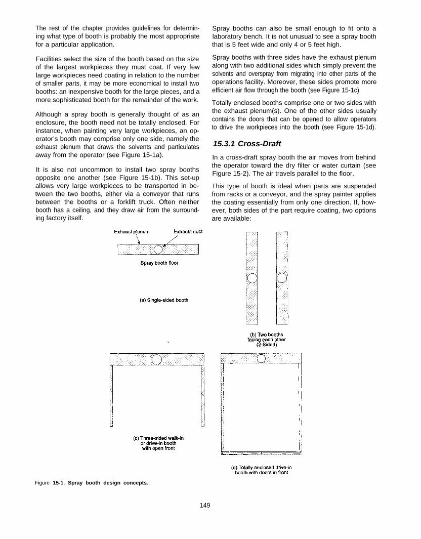
The rest of the chapter provides guidelines for determin- Spray booths can also be small enough to fit onto aing what type of booth is probably the most appropriate laboratory bench. It is not unusual to see a spray boothfor a particular application. that is 5 feet wide and only 4 or 5 feet high.
Facilities select the size of the booth based on the sizeof the largest workpieces they must coat. If very fewlarge workpieces need coating in relation to the numberof smaller parts, it may be more economical to install twobooths: an inexpensive booth for the large pieces, and amore sophisticated booth for the remainder of the work.
Spray booths with three sides have the exhaust plenumalong with two additional sides which simply prevent thesolvents and overspray from migrating into other parts of theoperations facility. Moreover, these sides promote moreefficient air flow through the booth (see Figure 15-1c).
Although a spray booth is generally thought of as anenclosure, the booth need not be totally enclosed. Forinstance, when painting very large workpieces, an op-erator’s booth may comprise only one side, namely theexhaust plenum that draws the solvents and particulatesaway from the operator (see Figure 15-1a).
Totally enclosed booths comprise one or two sides withthe exhaust plenum(s). One of the other sides usuallycontains the doors that can be opened to allow operatorsto drive the workpieces into the booth (see Figure 15-1d).
15.3.1 Cross-Draft
It is also not uncommon to install two spray boothsopposite one another (see Figure 15-1b). This set-upallows very large workpieces to be transported in be-tween the two booths, either via a conveyor that runsbetween the booths or a forklift truck. Often neitherbooth has a ceiling, and they draw air from the surround-ing factory itself.
In a cross-draft spray booth the air moves from behindthe operator toward the dry filter or water curtain (seeFigure 15-2). The air travels parallel to the floor.
This type of booth is ideal when parts are suspendedfrom racks or a conveyor, and the spray painter appliesthe coating essentially from only one direction. If, how-ever, both sides of the part require coating, two optionsare available:
Figure 15-1. Spray booth design concepts.
149
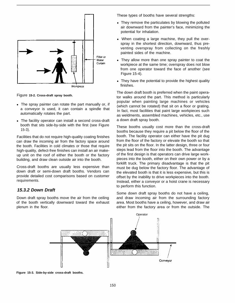
Figure 15-2. Cross-draft spray booth.
l The spray painter can rotate the part manually or, ifa conveyor is used, it can contain a spindle thatautomatically rotates the part.
l The facility operator can install a second cross-draftbooth that sits side-by-side with the first (see Figure15-3).
Facilities that do not require high-quality coating finishescan draw the incoming air from the factory space aroundthe booth. Facilities in cold climates or those that requirehigh-quality, defect-free finishes can install an air make-up unit on the roof of either the booth or the factorybuilding, and draw clean outside air into the booth.
Cross-draft booths are usually less expensive thandown draft or semi-down draft booths. Vendors canprovide detailed cost comparisons based on customerrequirements.
15.3.2 Down Draft
Down draft spray booths move the air from the ceilingof the booth vertically downward toward the exhaustplenum in the floor.
These types of booths have several strengths:
l They remove the particulates by blowing the pollutedair downward from the painter’s face, minimizing thepotential for inhalation.
l When coating a large machine, they pull the over-spray in the shortest direction, downward, thus pre-venting overspray from collecting on the freshlypainted sides of the machine.
l They allow more than one spray painter to coat theworkpiece at the same time; overspray does not blowfrom one operator toward the face of another (seeFigure 15-4).
l They have the potential to provide the highest qualityfinishes.
The down draft booth is preferred when the paint opera-tor walks around the part. This method is particularlypopular when painting large machines or vehicles(which cannot be rotated) that sit on a floor or grating.In fact, most facilities that paint large workpieces suchas weldments, assembled machines, vehicles, etc., usea down draft spray booth.
These booths usually cost more than the cross-draftbooths because they require a pit below the floor of thebooth. The facility operator can either have the pit dugfrom the floor of the factory or elevate the booth so thatthe pit sits on the floor. In the latter design, three or foursteps lead from the floor into the booth. The advantageof the first design is that operators can drive large work-pieces into the booth, either on their own power or by aforklift truck. The primary disadvantage is that the pitmust be dug below the factory floor. The advantage ofthe elevated booth is that it is less expensive, but this isoffset by the inability to drive workpieces into the booth.Instead, either a conveyor or a hoist crane is necessaryto perform this function.
Some down draft spray booths do not have a ceiling,and draw incoming air from the surrounding factoryarea. Most booths have a ceiling, however, and draw aireither from the factory area or from the outside. The
Operator
Figure 15-3. Side-by-side cross-draft booths.
150

Figure 15-4. Down draft spray booth.
need for a heated or unheated air make-up unit dependson climatic conditions and the need for a high quality,defect-free finish. For instance, it is always advanta-geous to maintain the booth temperature at between 65o
and 8OoF, but very few companies feel they can affordthe cost of controlling the temperature of high volumeair flow rates. Facilities that produce high-quality fin-ishes and are located in very cold climates (in winter)and/or very hot climates (in summer), however, oftenhave little choice but to provide temperature controls.
Similarly, it is usually beneficial to control the relativehumidity in the booth at less than 50 percent, particularlywhen using water-borne coatings, polyurethanes, andother moisture-sensitive resins. This is because humid-ity can affect the drying time of water-borne coatings,while it can cause blemishes in polyurethane coatings.The costs associated with controlling humidity can beprohibitive. Despite these high costs, companies thatmust produce high-quality finishes free from defects doindeed need to invest in air conditioning controls.
While the capital cost of a down draft booth usuallyexceeds that of a cross-draft booth, the operating ex-pense is almost always considerably higher, primarilybecause of higher air flow requirements.
For example, Occupational Safety and Health Admini-stration (OSHA) requires that the minimum air velocitythrough a spray booth exceeds 100 feet per minute(fpm) in the direction of the exhaust plenum or filterbank, and primarily away from the face of the operator.The following equation expresses the volumetric air flow:
Volumetric flow = Velocity (fpm) x Cross-(cfm) sectional area (square feet)
of the filter opening
Consider two spray booths, each of identical interiordimensions. If the booth is 10 feet high x 8 feet wide x
15 feet deep, then for a cross-draft booth the minimumair flow would be:
8,000 cfm = 100 (fpm) x 10 feet x 8 feet
If the booth is a down draft design, and the entire flooropening draws air, then the minimum air flow would be:
12,000 cfm = 100 (fpm) x 8 feet x 15 feet
In most cases, a down draft booth draws more air thana cross-draft booth, and the energy requirements in-crease proportionally. If the booth requires heat to warmthe air during the winter months, the energy require-ments are accentuated.
In addition, because the floor opening is usually signifi-cantly larger for a down draft booth than for a cross-draftdesign, the cost of replacing and disposing of spent dryfilters, water, and chemicals are considerably higher.
These are all factors a facility operator must considerbefore selecting a down draft booth.
15.3.3 Semi-down Draft
Semi-down draft booths offer two different designs.First, the booth can move the air from the ceiling at thefront of the booth toward the floor at the back of thebooth where the exhaust is located. Air movement is ina diagonal direction. Alternatively, the air can move fromthe center of the ceiling down toward one of two levelexhaust plenums located along the side walls of thebooth. Figure 15-5 illustrates these two types of semi-down draft designs.
Semi-down draft booths offer a compromise betweenthe cross-draft and down draft configurations and pro-vide many of the advantages of the other designs.
Companies choose between cross, down, and semi-down draft booths based on the type of workpieces theymust paint. When paint operators must walk around alarge workpiece, the choice is usually between a downor semi-down draft booth. The latter is less expensivebecause it does not require a pit below the floor for theexhaust plenum.
15.4 Dry Filter Spray Booths
Because the choice between dry filter, water-wash, andbaffle spray booths encompasses many issues, sepa-rate sections discuss each of these types of booths.
Vickers (2) estimates that 80 percent or more of spraybooths used in paint facilities are of the dry filter type. Inrecent years, many facilities have converted water-washbooths to dry filter because of their lower maintenancecosts and the often significantly lower hazardous wastecosts. The cost to actually purchase dry filters ranges
151
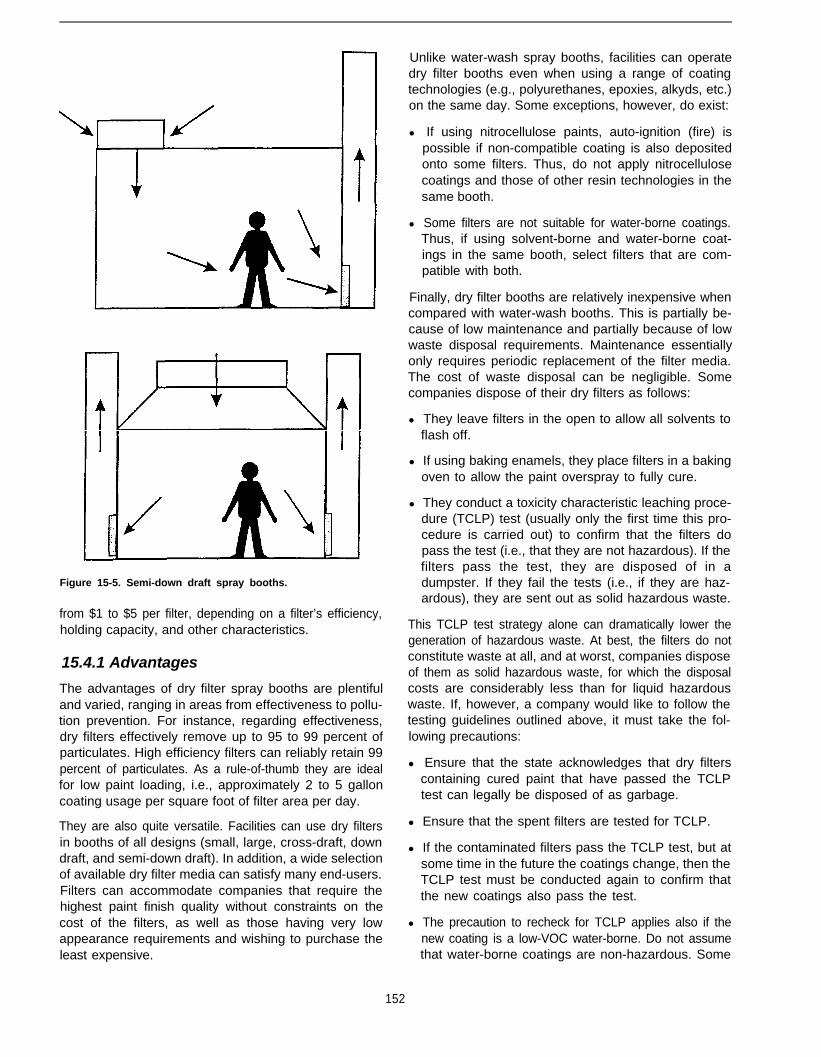
Figure 15-5. Semi-down draft spray booths.
from $1 to $5 per filter, depending on a filter’s efficiency,holding capacity, and other characteristics.
15.4.1 Advantages
The advantages of dry filter spray booths are plentifuland varied, ranging in areas from effectiveness to pollu-tion prevention. For instance, regarding effectiveness,dry filters effectively remove up to 95 to 99 percent ofparticulates. High efficiency filters can reliably retain 99percent of particulates. As a rule-of-thumb they are idealfor low paint loading, i.e., approximately 2 to 5 galloncoating usage per square foot of filter area per day.
They are also quite versatile. Facilities can use dry filtersin booths of all designs (small, large, cross-draft, downdraft, and semi-down draft). In addition, a wide selectionof available dry filter media can satisfy many end-users.Filters can accommodate companies that require thehighest paint finish quality without constraints on thecost of the filters, as well as those having very lowappearance requirements and wishing to purchase theleast expensive.
Unlike water-wash spray booths, facilities can operatedry filter booths even when using a range of coatingtechnologies (e.g., polyurethanes, epoxies, alkyds, etc.)on the same day. Some exceptions, however, do exist:
l If using nitrocellulose paints, auto-ignition (fire) ispossible if non-compatible coating is also depositedonto some filters. Thus, do not apply nitrocellulosecoatings and those of other resin technologies in thesame booth.
l Some filters are not suitable for water-borne coatings.Thus, if using solvent-borne and water-borne coat-ings in the same booth, select filters that are com-patible with both.
Finally, dry filter booths are relatively inexpensive whencompared with water-wash booths. This is partially be-cause of low maintenance and partially because of lowwaste disposal requirements. Maintenance essentiallyonly requires periodic replacement of the filter media.The cost of waste disposal can be negligible. Somecompanies dispose of their dry filters as follows:
l They leave filters in the open to allow all solvents toflash off.
l If using baking enamels, they place filters in a bakingoven to allow the paint overspray to fully cure.
l They conduct a toxicity characteristic leaching proce-dure (TCLP) test (usually only the first time this pro-cedure is carried out) to confirm that the filters dopass the test (i.e., that they are not hazardous). If thefilters pass the test, they are disposed of in adumpster. If they fail the tests (i.e., if they are haz-ardous), they are sent out as solid hazardous waste.
This TCLP test strategy alone can dramatically lower thegeneration of hazardous waste. At best, the filters do notconstitute waste at all, and at worst, companies disposeof them as solid hazardous waste, for which the disposalcosts are considerably less than for liquid hazardouswaste. If, however, a company would like to follow thetesting guidelines outlined above, it must take the fol-lowing precautions:
l Ensure that the state acknowledges that dry filterscontaining cured paint that have passed the TCLPtest can legally be disposed of as garbage.
l Ensure that the spent filters are tested for TCLP.
l If the contaminated filters pass the TCLP test, but atsome time in the future the coatings change, then theTCLP test must be conducted again to confirm thatthe new coatings also pass the test.
l The precaution to recheck for TCLP applies also if thenew coating is a low-VOC water-borne. Do not assumethat water-borne coatings are non-hazardous. Some
152

contain heavy metals and other ingredients thatwould cause the filters to fail the test.
l Holding capacity
l Incineration profile
15.4.2 Disadvantages l Biodegradability
While dry filters are ideal for some paint facilities, theydo have limitations. For instance, they are generally notappropriate for large coating usage, i.e., greater than 5gallons per square foot of filter area per day. They alsohave disadvantages that affect their pollution and safetyprofiles, as well as their cost.
l Landfill option profile
l Flammability
l Suitability for various coatings
Unless using continuous roll-up filters, which are pro-hibitively expensive for most companies, air flowthrough the booth diminishes as the filters load up withoverspray. This can be a major drawback if air flow playsan important role in the finishing operation. (See CaseStudy #3 in Chapter 16.) In some facilities, an enclosedfinishing room comprises several spray booths. In mostcases, the booths do not each have an air make-up unit,but all draw air from only one inlet duct. As each dry filtersection becomes loaded with overspray, the air flowwithin the finishing room constantly changes, causingquality problems. Turning the blowers on and off duringthe working shift aggravates the situation. In extremecases, the air flow can become so turbulent that itcontinuously changes direction (e.g., moving toward thefilter bank for a few seconds, and then reversing itselffor the next few seconds). Such turbulent air can carryoverspray from one booth onto freshly painted surfacesin the other booth(s). This cross-contamination can leadto very expensive reworks and rejects, and ultimatelyresults in unnecessary pollution and costs. Anotherpollution-related consideration is that dry filters do notremove VOCs.
Efficiency is the ability of the filter to remove particulatesbefore they can enter the exhaust stack. Selecting afilter that has a high retention efficiency, at least 96 to99 percent, is important. Note, however, that the effi-ciency only affects the amount of particulates, or PMlo,that escapes into the air. Some state regulations placedaily limits on the amount of PMlo that facilities can emit,and here the retention efficiency of the filters can becrucial to compliance.
If the efficiency is relatively low, less than 96 percent,escaping particulates can possibly settle outdoors, evenon vehicles in the employee parking lot. Companies thathave experienced these problems have found it wellworth the expense to purchase higher efficiency filters.Also, note that the retention efficiency of the filters hasno bearing on the amount of hazardous waste that mayrequire disposal.
153
Regarding safety, dry filters are a potential fire hazard,particularly if dry overspray is allowed to build up. Over-spray of coatings, such as nitrocellulose lacquers, cancause spontaneous combustion. Fortunately, nitrocellu-lose coatings are phasing out and states that enforcelow VOC limits on coatings have all but outlawed them.Because of their risk of fire, installation of a sprinklersystem is a requirement.
In addition, high efficiency filters reduce the loading ofoverspray on surfaces inside the spray booth exhaustduct, and particularly on the fan impeller. This, in turn,reduces the frequency with which the interior section ofthe booth requires cleaning. If a significant amount ofoverspray escapes into the spray booth stack, it canincrease the energy required to drive the impeller. Highefficiency filters minimize this problem.
Resistance of a filter refers to the pressure differentialthat ensues when the high velocity air passes across thefilter bank. Facilities should select a filter with low air flowresistance. While this strategy lowers the energy costsrequired to run the booth, it is unlikely to have an impacton pollution.
Finally, storage of unused filters requires space. Facili-ties with large spray booths may find this problematic.In addition, used, spent filters are bulky and also occupymuch space. This potentially increases the cost of dis-posal.
15.4.3 Selecting Dry Filter Media
When selecting the proper dry filter, facilities need totake into account several filter characteristics. Amongthese are:
l Efficiency
l Resistance
Holding capacity is the amount of overspray that a filtercan hold or retain during its service life. Selecting a filtermedium with a high loading capacity is wise. This re-duces the frequency for replacing the filters, and re-duces the volume of waste that may require disposal ashazardous solid waste.
Facilities should check on whether they can incineratethe filters and that the filters meet all incinerator stand-ards. This gives the end-user the option to incinerate thefilters rather than to dispose of them as a solid hazardousor non-hazardous waste. The end-user should first de-termine whether incineration is an acceptable procedurewithin the state. Some states may not allow incineration

by the end-user, although a certified waste incinerationcompany may be able to perform this function.
Facilities also may find it advantageous to use filters thatare biodegradable. Regardless of this, facilities shouldcheck to ensure that the filters meet all landfill standards.
Another important factor is flammability. Check that thefilters meet the requirements of the National Fire Protec-tion Bulletin #33 and that Underwriter’s Laboratories hasapproved the filters as Class 2.
Finally, some water-borne coatings can complicate thechoice of dry filter used. Some filters, particularly if madeof paper, may not be suitable for water-borne coatings.
The literature contains very little concerning the selec-tion of dry filters for capturing paint particulates. Vickers(2) provides some interesting information about thematerials manufacturers use to make spray booth fil-ters. Howery (3) has presented an excellent paper ad-dressing the properties of different dry filter media (seeTable 15-2).
Table 15-2 shows that when filtering high solids bakingenamel, filters such as the standard filter have a lowretention efficiency of 96.5 to 97.5 percent and a lowholding capacity of only 2.8 pounds per filter pad. Com-pare this with the high efficiency filter that has a retentionefficiency of 98.5 to 99 percent and a correspondingholding capacity of 5.4 pounds per filter pad. The stand-ard filter is a low-cost paper or cardboard filter, while thehigh efficiency filter comprises several layers of material,including Kraft paper and several layers of fiberglassmatting, each with progressively smaller porosities.
Tables 15-3 and 15-4 provide the worksheets for hypo-thetical paint facilities using 65 and 30 percent transfer
Table 15-2. Efficiency and Holding Capacity of Dry Filtersa (3)
Description Efficiency Holding Capacity
High Solids BakingEnamel Average Holding Capacityb
Efficiency Range (inches, water column)
Standard filter 96.5 - 97.5 2.8 Ibs @ 0.10
High-capacity filter 94.0 - 96.0 6.5 Ibs @ 0.10
High-efficiency filter 98.5 - 99.5 5.4 Ibs @ 0.50
Water-Borne BakeEnamel Average Holding Capacityb
Efficiency Range (inches, water column)
Standard filter 93.0 - 94.0 4.8 Ibs @ 0.50
High-capacity filter 91.5 - 92.5 8.7 Ibs @ 0.50
High-efficiency filter 97.0 - 98.0 4.0 Ibs @ 0.50a Performance figures were obtained using representative current in-
dustry coatings in an air-atomizing gun with two pads in tandem ata face velocity of 200 fpm.
b Test paint was very fluid and slow drying, resulting In excessiverun-off on standard and high-capacity filters, with little resistanceincrease.
efficiency as the basis. Both values seem reasonable fora typical paint facility. The 30 percent value representsthe average small-to-medium parts facility, while the 65percent value represents medium-to-large size partsand machines. This worksheet model allows one to
Table 15-3. Cost of Waste With 65 Percent Transfer Efficiency
Table of Assumptions (Vary Filter Holding Capacityand Cost of Filter)
Surface area to be coated
VOC of coating
Density of VOC portion
% Volume solids
Weight per gal (WPG)
% Weight solids (Calculated)
Cost of coating
Dry film thickness
Transfer efficiency
Size of filters
Number of filters across
Number of filters down
Total number filters affected
Holding capacity of filters
Percent of overspray going into filters
Percent efficiency of the filters
Percentage PMlo in the overspray
Cost of filters
Number of filters which can bedisposed of in 55-gal drum
Cost to dispose of 55-gal drum
Days of operation
Labor required to replace filters
Labor rate
Calculations
Total liquid gallons required
Total liquid coating used
Total solid coating used
Density of solid coating (Calculated)
Weight of solid coating used
Weight of total solid overspray
Weight of solid overspray in filters
Number of filters to be disposed of
Number of filter changes per year
Number of 55.gallon drums to bedisposed of
Cost of hazardous waste disposal
Cost of filters
Labor hours to change filters
Labor cost to change filters
Number of wasted gallons
Cost of wasted paint
SummaryCost of waste + filters + labor
Cost of wasted paint
Total cost of waste
3,500.00 ft2/day
3.5 lb/gal
7.36 lb/gal
52.45%
9.8 lb/gal
64.29%
$20.00 $/gal
1.5 mil
65%
20” x 20”
8
4
32
3 lb/filter
60%
99%
99%
$1.OO/filter
40 filters/drum
$300.00 $/drum
251 days/yr
0.5 hours
$15.00 $/hour
9.60 gal/day
2,409.94 gal/yr
1,263.91 solid gal/yr
12.01 lb/gal
15,182.61 lb solid/yr
5,313.91 lb solid/yr
3,188.35 lb solidlyr
1,062.78 filters/yr
33.21 filter changes/yr
26.57 drums/yr
$7,970.87 $/yr
$1,062.78 $/yr
16.61 hours/yr
$249.09 $/yr
843.48 gal/yr
$16,869.56 $/yr
$9,282.74 $/yr
$16,869.56 $/yr
$26,152.30 $/yr
154
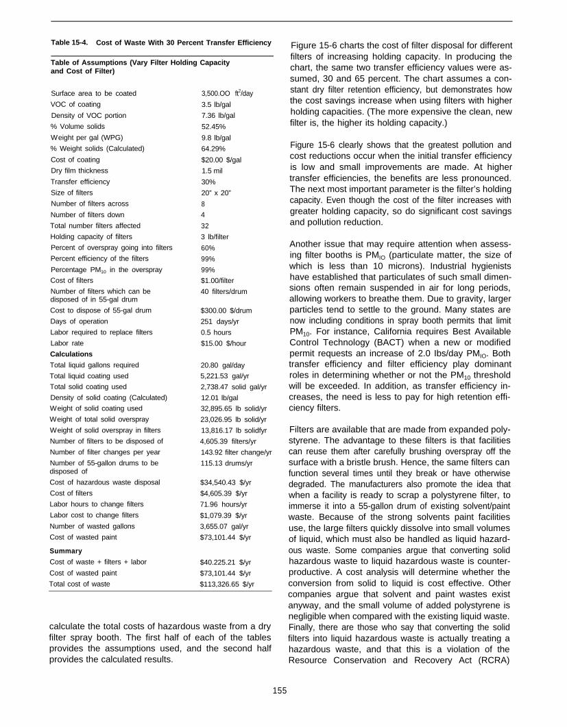
Table 15-4. Cost of Waste With 30 Percent Transfer Efficiency
Table of Assumptions (Vary Filter Holding Capacityand Cost of Filter)
Surface area to be coated
VOC of coating
Density of VOC portion
% Volume solids
Weight per gal (WPG)
% Weight solids (Calculated)
Cost of coating
Dry film thickness
Transfer efficiency
Size of filters
Number of filters across
Number of filters down
Total number filters affected
Holding capacity of filters
Percent of overspray going into filters
Percent efficiency of the filters
Percentage PM10 in the overspray
Cost of filters
Number of filters which can bedisposed of in 55-gal drum
Cost to dispose of 55-gal drum
Days of operation
Labor required to replace filters
Labor rate
Calculations
Total liquid gallons required
Total liquid coating used
Total solid coating used
Density of solid coating (Calculated)
Weight of solid coating used
Weight of total solid overspray
Weight of solid overspray in filters
Number of filters to be disposed of
Number of filter changes per year
Number of 55-gallon drums to bedisposed of
Cost of hazardous waste disposal
Cost of filters
Labor hours to change filters
Labor cost to change filters
Number of wasted gallons
Cost of wasted paint
Summary
Cost of waste + filters + labor
Cost of wasted paint
Total cost of waste
3,500.OO ft2/day stant dry filter retention efficiency, but demonstrates how
3.5 lb/gal the cost savings increase when using filters with higher
7.36 lb/gal holding capacities. (The more expensive the clean, new
52.45% filter is, the higher its holding capacity.)
9.8 lb/gal
64.29% Figure 15-6 clearly shows that the greatest pollution and
$20.00 $/gal cost reductions occur when the initial transfer efficiency
1.5 mil is low and small improvements are made. At higher
30% transfer efficiencies, the benefits are less pronounced.
20” x 20” The next most important parameter is the filter’s holding
8 capacity. Even though the cost of the filter increases with
4 greater holding capacity, so do significant cost savings
32 and pollution reduction.
3 lb/filter
60% Another issue that may require attention when assess-
99% ing filter booths is PMIO (particulate matter, the size of
99% which is less than 10 microns). Industrial hygienists
$1.00/filter have established that particulates of such small dimen-
40 filters/drum sions often remain suspended in air for long periods,allowing workers to breathe them. Due to gravity, larger
$300.00 $/drum particles tend to settle to the ground. Many states are251 days/yr now including conditions in spray booth permits that limit0.5 hours PM10. For instance, California requires Best Available$15.00 $/hour Control Technology (BACT) when a new or modified
permit requests an increase of 2.0 Ibs/day PMIO. Both20.80 gal/day transfer efficiency and filter efficiency play dominant5,221.53 gal/yr roles in determining whether or not the PM10 threshold2,738.47 solid gal/yr will be exceeded. In addition, as transfer efficiency in-12.01 lb/gal creases, the need is less to pay for high retention effi-32,895.65 lb solid/yr ciency filters.23,026.95 lb solid/yr
13,816.17 lb solidfyr Filters are available that are made from expanded poly-4,605.39 filters/yr styrene. The advantage to these filters is that facilities143.92 filter change/yr can reuse them after carefully brushing overspray off the115.13 drums/yr surface with a bristle brush. Hence, the same filters can
function several times until they break or have otherwise$34,540.43 $/yr degraded. The manufacturers also promote the idea that$4,605.39 $/yr when a facility is ready to scrap a polystyrene filter, to71.96 hours/yr immerse it into a 55-gallon drum of existing solvent/paint$1,079.39 $/yr waste. Because of the strong solvents paint facilities3,655.07 gal/yr use, the large filters quickly dissolve into small volumes$73,101.44 $/yr of liquid, which must also be handled as liquid hazard-
ous waste. Some companies argue that converting solid$40.225.21 $/yr hazardous waste to liquid hazardous waste is counter-$73,101.44 $/yr productive. A cost analysis will determine whether the$113,326.65 $/yr conversion from solid to liquid is cost effective. Other
companies argue that solvent and paint wastes existanyway, and the small volume of added polystyrene isnegligible when compared with the existing liquid waste.
Figure 15-6 charts the cost of filter disposal for differentfilters of increasing holding capacity. In producing thechart, the same two transfer efficiency values were as-sumed, 30 and 65 percent. The chart assumes a con-
calculate the total costs of hazardous waste from a dry Finally, there are those who say that converting the solidfilter spray booth. The first half of each of the tables filters into liquid hazardous waste is actually treating aprovides the assumptions used, and the second half hazardous waste, and that this is a violation of theprovides the calculated results. Resource Conservation and Recovery Act (RCRA)
155

Figure 15-6. Cost of filter disposal based on holding capacity.
regulations. The journal Metal Finishing further detailed With time, the water becomes contaminated with bacte-this complex issue in its May 1995 issue (4). ria and requires disposal.
This is a controversial topic. Each company must decideits best option based on its own policy, the facts surround-ing its individual situation, and its own state’s regulations.
15.5 Water-Wash Spray Booths
The most important alternative to dry filter spray boothsare water-wash booths. Instead of collecting oversprayin the filter bank, a constant stream of water in anentrainment section scrubs the overspray from the airthat the booth exhausts. Some water-wash booths aredesigned with a water curtain, but this is not a prereq-uisite. Most commonly, cross-draft and semi-down draftbooths have water curtains while down draft booths do not.
To prevent these unfortunate occurrences, the waterneeds treatment with one or more chemicals designedto detackify the overspray particles (i.e., remove thestickiness). Properly selecting the chemical(s) allows forlong-term recycling of the water in the booth and re-duces the frequency of the dumps. Paint facilities thatimplement regular and thorough maintenance programsrun their booths for up to one year and more beforeexchanging the water in the trough.
15.5.1 Advantages
Water flowing down the curtain collects much of theoverspray, but the scrubbing action in the entrainmentsection is more important. In the entrainment section,fixed baffles force the exhaust air to constantly changedirection and, as this occurs, the water scrubs the par-ticulates from the air or they simply fall into the watertrough.
Water-wash spray booths are ideal when using largequantities of coatings, usually more than 5 gallons perday per square foot of face area. These booths areavailable in any type of booth design (i.e., small, large,open, closed, cross-draft, down draft, semi-down draft).Water-wash booths can effectively and efficiently re-move particulates. Efficiency of approximately 99 per-cent is possible.
Even after the overspray enters the water, it remainssticky and can plug up holes, nozzles, pipes, andpumps. In addition, it can form a deposit on the watercurtain, slowly building up a layer that eventually im-pedes the smooth water flow down the curtain’s face.
Unlike dry filter spray booths, the air velocity through thebooth remains constant, provided that operators prop-erly maintain the water trough. This helps to manage theoverspray. In addition, facilities may choose to usechemicals (deflocculants) that either sink, float, or dis-perse the paint overspray.
156
Another benefit of such booths is that they provideessentially low fire risk.
15.5.2 Disadvantages
Like dry filter spray booths, water-wash spray booths donot remove VOC’s, except for a small concentrationdissolved in the water. Other issues also relate to theirpracticality.
The most effective method for selecting a spray boothdeflocculant involves sending a one quart sample ofeach coating to a chemical vendor, together with detailsof the booth design. The vendor can carry out tests todetermine which chemical or combination of chemicalswould remove the stickiness quickly and efficiently.
For instance, they are more expensive to install andoperate than are dry filter booths. Also, although theyprovide low fire risk, like dry filter booths, they requireinstallation of a sprinkler system. Facilities, therefore,cannot realize cost savings in this feature. In addition,because of the water trough and entrainment area, theyusually require slightly more space than a dry filterbooth.
Depending on the type of coating they are using, opera-tors may need to also use a defoamer. This preventsfoam from building up at the water/curtain interface andallows the booth to continue functioning normally. If toomuch foam builds up, it can affect the pressure differen-tials that are necessary for the proper function of thebooth.
Note that a chemical effective for one type of coatingresin may not be effective for another. The type ofcoatings being spray-applied, therefore, dictates the se-lection of chemicals.
Maintaining water-wash spray booths also has somedrawbacks. Operators must remove paint sludge fromthe water and dispose of it in order to prevent pluggingof fluid passages. In addition, after running the booth forseveral months, the water will eventually require disposal.
Finally, water-wash spray booths require regular moni-toring for:
l Level of water in trough
l Concentration of chemicals to detackify paint
A problem can arise when applying more than one typeof coating in the same booth. For instance, if operatorsapply high solids solvent-borne polyurethanes as well aswater-borne alkyds in the same water-wash booth, pos-sibly no single chemical, or even combination of chemi-cals would effectively perform. In such a case, operatorsmay need to segregate the painting by applying thesolvent-borne polyurethanes in one booth and thewater-borne alkyds in another. While this may seemunreasonable, it may constitute the best solution to theproblem.
l Foaming
l Rancidity
15.5.3 Selecting the Appropriate Chemicals
The correct choice of chemical deflocculant and de-foamer is essential to the efficient operation of a water-wash booth. Some chemicals are available as solids orliquids. The more expensive chemicals detackify thepaint sludge and dewater it, thus reducing the volume ofsludge requiring disposal.
157
Available chemicals can sink, float, or disperse paintsludge. Choosing between them depends entirely on thedesign of the booth. For instance, if the booth drawswater from the bottom of the trough and circulates it tothe top of the water curtain, one would not want adeflocculant that causes the overspray to sink. In sucha booth, paint sludge at the bottom of the trough wouldfind its way into the pump and piping, eventually block-ing these passages. In this situation, a deflocculant thatallows the overspray to float or disperse in the wateris best.
If, on the other hand, the booth draws water from the topof the trough and pumps water to the curtain, the pre-ferred choice would be a deflocculant that sinks or dis-perses the paint sludge.
15.5.4 Methods for Treating Water FromWater- Wash Booths
One of the most important sources of hazardous wastefrom a water-wash spray booth is the water troughwhere the paint sludge collects.
Facilities can use several mechanisms to prolong theuseful life of the water itself and minimize the disposalof the paint waste.
First, if the paint sludge sinks, operators can shovel outthe booth, dropping the sludge into a 55-gallon drum.Invariably, however, the sludge is wet and contains ahigh percentage of water. Its disposal, therefore, gener-ates an unnecessarily high volume of waste.
Alternately, if the sludge floats to the top, a weir placedat the top of the water level can collect it. Operators canthen scoop it into a 55-gallon drum. Or, the sludge canfeed into a centrifuge or a perforated drum that sepa-rates the sludge from the water. Provided that operatorstreat the water with a biocide to prevent rancidity, theycan return it to the water trough for further use.
The most effective method for removing the sludge andminimizing the amount of water the sludge carries, how-ever, is to use a polymer deflocculant that not onlysuspends the sludge as fine particles in the water, but
also chemically dewaters it. This causes the sludge tono longer be sticky. It feels like wet sea sand. Filteringand removing this from the water is relatively easy usinga drum filter, centrifuge, or hydrocyclone.
Finally, at least one company provides a process thattakes the dry sludge (which has been dried in an oven),bakes and pulverizes it, and then sells the inert, non-hazardous waste for use as a raw material in the cementindustry.
15.6 Baffle Booths
A baffle spray booth is a less common alternative to bothdry filter and water-wash booths. In a baffle spray booth,the face of the booth has steel baffles that run the heightof the booth and are several inches wide. The bafflesusually overlap each other, forcing the air that passesthrough the booth to change direction in order to reachthe back of the booth. When the air does reach theentrainment section at the back, the paint particulates itwas carrying fall into a trough. Paint operators can thencollect the paint from the trough for reuse.
These booths are much less frequently used than eitherdry filter or water-wash booths. This is because unlessa company is reclaiming the paint, this booth offers noadvantage. In addition, not all paints can be reclaimed.Although the recycling opportunities associated withbaffle booths present strong pollution prevention bene-fits, most companies cannot use reclaimed paint and socannot take advantage of these benefits.
15.7 Best Management Practices ToMinimize Coating Defects in theSpray Booth
This section provides suggestions for minimizing thedefects that result in reworks and rejects.. The mostfrequent coating defects that relate directly to the func-tioning of a spray booth include:
Poor wrap when using electrostatic paints.
Dust and dirt in the finish.
Water spots in the finish.
Haziness (blushing) that detracts from the gloss.
Dry overspray on the finish.
Non-uniform coating finish with gloss patches, orangepeel, voids, etc.
Most of these defects often cause operators to performrework or in some cases to altogether reject the work-pieces they have coated. This of course leads to addi-tional pollution and waste. Avoiding the defects thenreduces unnecessary work and pollution.
15.7.1 Poor Wrap
This defect can derive from many possible reasons.Reasons that relate directly to the operation of the spraybooth, however, are the lack of a proper ground and toohigh or turbulent an air flow through the booth.
To prevent poor wrap when using electrostatic paint, afacility operator must ensure that the spray booth has aproper ground. Changing the air flow might require as-sistance from an air ventilation expert.
15.7.2 Dust and Dirt in the Finish
This is probably one of the most frequent causes forreworks and rejects. Often, a fully assembled machinemay require repainting because of dirt contamination.Unless the coating itself contains din the vendor did notstrain or filter out, the problem usually results from poorspray booth operation. Facilities should take severalmeasures and precautions to avoid this problem:
Ensure that sanding or other dirty operations do nottake place immediately outside the booth, as thebooth blowers would draw in the dust.
Ensure that the air filters at the air intakes of thebooth are not dirty or have too large a mesh size.
Ensure that the booth is operating under negativeinstead of positive pressure. In a closed booth, an airmake-up system should provide the incoming air,which should more than compensate for the air thebooth exhausts.
When an air make-up system draws fresh outside airinto the booth, ensure that its intake stack is not tooclose to the exhaust ducts from sanding and otherdirty operations.
Keep booth walls, floor, and ceiling free of loose, dryoverspray or booth blowers may pry panicles loose,allowing them to fall onto freshly painted surfaces.
Select the correct booth design.
Regarding the last bulleted item, as earlier sections ofthis chapter suggest, selecting the right booth design isessential. For instance, when coating large workpieces,use a down draft booth. Using a cross-draft booth wouldcause overspray to pass the sides of the freshly paintedworkpiece. If, however, using a cross-draft booth is un-avoidable, minimize the problem by starting the paintingoperation at the back of the workpiece and movingforward to the filter bank.
15.7.3 Water Spots in the Finish
When using a water-wash booth, operators must prop-erly clean the nozzles above the water curtain. Omittingthis step creates the possibility for water droplets tosettle on the painted finish.
158
15.7.4 Haziness That Detracts From theGloss
This problem can occur under high humidity conditionswhen moisture vapor condenses on freshly painted sur-faces and causes blushing. Clearly, this is more likely tohappen with a water-wash booth than a dry filter one. Inorder to avoid this problem, remove the workpiece fromthe booth shortly after painting. If freshly painted sur-faces remain in the spray booth overnight when theblowers are not on, humidity will quickly build up in thebooth, increasing the probability of moisture condensa-tion depositing on the cold metal surfaces.
If facilities cannot easily resolve this problem, they mayneed to convert the water-wash booth to dry filter.
15.7.5 Dry Overspray on the Finish
The most common reason for this defect is that thesolvent is too fast. As the solvent flashes off duringcoating application, the overspray loses its wetness andcannot easily incorporate onto the freshly painted sur-faces. While this problem is independent of the spraybooth, a high air velocity in the booth will aggravate thesituation. This, again, suggests that the air flow throughthe booth requires monitoring and controlling.
Another possible reason for dry overspray on the finisharises when more than one dry filter spray booth is beingused. If the air flow within the larger spray room (incor-porating the booths) is not uniform, overspray from onebooth can settle on the freshly painted surfaces in an-other booth. This problem points to the need for properair flow between all booths within the larger room. Onesolution is to provide each booth with its own air make-up unit.
15.7.6 Non-uniform Coating Finish With GlossPatches, Orange Peel, Voids, etc.
Numerous causes exist for such defects, but those thatare solely due to the spray booth are often associatedwith poor lighting. A vast number of spray booths areeither poorly lit or have overspray almost totally conceal-ing the glass panels that cover the lights. Providing agood looking finish is virtually impossible in such inade-quately lit and poorly maintained booths.
Facilities should provide lighting not only from the ceilingbut also from the sides of the booths. Most automotive,drive-in booths possess side lighting but very few three-sided, cross-draft booths have the same luxury. Invest-
ing in adequate lighting and regularcleaning of the coverplates will have a quick pay-back period in the form ofbetter looking finishes and fewer touch-ups and re-works.
Aside from lighting, other suggestions for avoiding orresolving problems of non-uniform coating finishes follow:
When using water-wash spray booths, strongly dis-courage spray painters from dropping paper cups,gloves, and other garbage into the water trough. Theyalso must not empty leftover paint from quart or gal-lon cans into the trough. The chemicals cannot de-tackify such a large mass at one time, resulting in asticky mess of paint that can plug fluid passages later.
Ensure that sanding dusts cannot enter the spraybooth. Before bringing a workpiece that has beenscuff sanded into a spray booth, wipe down the entiresurface with tack rags or wash it down with aqueousdetergents. Sanding dusts that remain can contami-nate freshly painted surfaces.
As stated earlier, if using electrostatic spray guns,properly ground the booth and/or conveyor. Do notassume that they are grounded; only an ohmmetercan confirm grounding.
Ensure you select the proper dry filter media for adry filter booth. Selection guidelines appear in Sec-tion 15.4.3.
15.8 ReferencesAyer, J. 1995. Recirculation ventilation in paint spray booths: Newinsights. Metal Finishing 93:20.
Vickers, T.W. 1995. Selecting your best route to proper overspraycollection. In: Metal Finishing Organic Guide Book and Directory,vol. 93 (No. 4A), p. 236. New York, NY: Elsevier Science Publish-ers.
Howery, J. 1984. How much do you know about spray boothexhaust? Products Finishing 465 (May).
Joseph, R. 1995. Dealing with solvent distillation of waste paintfilters. Metal Finishing 93:44.
15.9 Additional ReadingJoseph, R. 1993. Pollution prevention in a paints and coatings facility.
Ron Joseph & Associates, Saratoga, CA.
DeVilbiss. No date. Spray booth basics. DeVilbiss Spray Booth Prod-ucts, Atlanta, GA 30336. Product literature.
Thomas, B. 1995. Spray booths. In: Metal Finishing Organic GuideBook and Directory, vol. 93 (No. 4A), p. 213. New York, NY:Elsevier Science Publishers.
159

Section 4Problem Solving
161
Chapter 16Problem Solving: Case Studies of Some Typical Paint Facilities
16.1 Introduction
This publication has tried to demonstrate how simpleand often inexpensive strategies can resolve productionand pollution problems. This chapter presents severalrealistic paint facility scenarios that reflect typical day-to-day production problems. Suggested solutions followeach presented problem. In almost all cases, the solu-tion to a technical problem leads to improved quality of thefinished product, reduced costs, and pollution prevention.
The three scenarios this chapter discusses are:
l Case Study #l: Flaking paint on tool boxes.
l Case Study #2: High reject rate and volatile organiccompounds (VOC) emissions from aluminum lamphousings.
l Case Study #3: Start-up problems for automotivecomponent manufacturer.
It should become clear to the reader that by improvingthe painting processes for the sake of efficiency and thequality of the finished product, pollution minimizationbecomes an automatic consequence.
16.2 Case Study #I : Flaking Paint on ToolBoxes
16.2.1 Background of Problems
Company A manufactures tool boxes that it sells to largeretail stores. Customers have complained that the coat-ings on some, but not all of the boxes, have flaked off insmall chips. Several thousand boxes, good and bad,have been returned for refinishing. Knowing about theusual coating process the company uses, of course, isessential.
The boxes are made of cold rolled steel. Surface prepa-ration comprises a three-stage spray washing processplus a drying stage. These stages are:
l Stage #l: Degrease and iron phosphate
l Stage #2: Tap-water rinse (intermittent overflow)
l Stage #3: Tap-water rinse
l Stage #4: Dry-off oven at 230°F
Operators load the parts onto a conveyor immediatelybefore they enter the first stage of the washer. Afterrunning through the washing and dry-off process, theconveyor then passes through the priming spray boothand finishing spray booth. The facility uses a fast-dryingalkyd primer and topcoat system. The conveyor thenloops the parts back to the spray washer where they areoff-loaded before they can go through the washer asecond time. The parts are sufficiently dry to be off-loaded.
Before going ahead with the refinishing process, Com-pany A needs to identify which boxes are good fromthose which are likely to fail. By conducting an adhesiontest, such as the Tape Adhesion Test described in Ameri-can Society of Testing and Materials D3359, Method B,the quality control department can distinguish betweenthe good boxes and those that will likely fail. In this test,a quality control operator applies a short piece (approxi-mately 3 inches) of masking tape or, preferably, alumi-num duct tape to the coating. After about 90 seconds,the tape is quickly removed by pulling back 180o. Ifcoating does not peel away with the tape, the coating isgood. If pieces of coating lift off onto the tape, thecoating has poor adhesion, and the quality control op-erator considers it a failure.
The issues the company must address then are:
l After identifying the bad boxes, how should CompanyA strip the coatings?
l What are the likely causes of the inconsistent problem?
What strategies should the company follow to im-prove the quality of the finish and to prevent similaroccurrences in the future?
Do any pollution minimization opportunities presentthemselves?
16.2.2 Possible Solutions
To identify and nullify the problem, Company A shouldfirst assess the whole process it will use to strip andrecoat the boxes.
The stripping method must be fairly rapid because thou-sands of boxes require stripping. Also, the companymust keep the cost to a minimum because the boxes
162
themselves are inexpensive. If the stripping process istoo costly, it no longer pays to refinish them.
Chemical stripping is a possibility but it requires severalsteps. Moreover, if any chemicals remain on the surfaceor if water ingresses between spot-welded plates, paintfailures can re-occur. Air, water, and waste pollution alsoare major negating factors.
Mechanical stripping in the form of abrasive blastingusing grit, aluminum oxide, or another such abrasiveprobably offers the greatest advantages. While the proc-ess should be relatively fast, the abrasive cannot be toocoarse or it will deform the boxes, and misalignment ofthe lids is a serious concern. The company might seri-ously consider plastic bead blasting because the beadsare unlikely to damage the metal surfaces. Moreover,the beads can be recycled and only the paint chipsrequire disposal. If the waste passes the TCLP tests, thecompany can dispose of it as non-hazardous solid waste.
Although a three-stage washer is not ideal for treating acold rolled steel substrate, it is usually adequate for theintended purpose, namely to coat the tool boxes. Theprocess requires careful control, however, to ensuregood paint adhesion. Operators must perform qualitycontrol checks on the temperature of the first stage (perthe chemical manufacturer’s recommendations), on thepH and free acid of the bath, and on the contact timebetween the steel and the chemical.
Poor rinsing practices can also contribute to the failures,specifically with a three-stage process. In this scenario,Stage #2 overflows on an intermittent basis. This sug-gests that contamination from Stage #1 can build up toan unspecified level before the water is diluted withmake-up tap water. Company A, therefore, should pro-vide for continuous overflow. In addition, the company’smanufacturing engineers should study the hanging ofparts from the conveyor to minimize drag-out from Stage#l to Stage #2.
Stage #3 is also a tap-water rinse. This can pose aproblem if the tap water contains a relatively high con-centration of dissolved solids. In an ideal process, thesecond rinse tank includes a sealer that consolidatesthe phosphate film. Moreover, deionized water worksbetter than tap water. In reality, however, it may not becost-effective nor necessary for Company A to incur theexpense of a deionized water generator. Tool boxes arenot the type of commodity that warrants a sophisticatedfinish. At the very least, though, Stage #3 should be anonchromate seal rinse, for which the added cost isminimal. (A chromate seal rinse often offers better pro-tection, but poses an environmental problem.)
The next stage uses the dry-off oven. In this scenario,the dry-off oven temperature is too low. For rapid dryingof the wet parts, the oven temperature should be greater
than 300°F. The low temperature allows parts to flashrust even before they have left the oven.
A quick drying alkyd system has the advantage of pre-cluding the need for a paint baking or curing oven. Thecompromise Company A makes when selecting such acoating, however, is that the coating film is often hardand brittle. Slower drying alkyds tend to have betterflexibility and adhesion properties, but to keep up withproduction speeds the company might need to install aforce-dry oven. The company should, therefore, re-ex-amine its selection of coating.
Although each step in the process has been reviewed,one final important factor remains: the conveyor systemitself is associated with problems. The conveyor passesthrough the spray washer, dry-off oven, and the twopaint spray booths. A common problem resulting fromthis configuration is that the spray painter in either of thespray booths has the ability to start and stop the line atwill. This occurs during coffee and lunch breaks, or whenthe spray painter needs to perform another function,such as filling the pressure pot with fresh coating. Whenthe conveyor stops, several of the parts still in the spraywasher may be between stages. If the stoppage lastsfor more than a few minutes, the parts might start to flashrust or may receive too heavy a phosphate coating.Parts that have proceeded through the rinse stages buthave stopped short of the dry-off oven will be left wet fortoo long. Quick drying is critical to prevent flash rusting.This intermittent action would also explain why onlysome, and not all, tool boxes fail. To avoid these prob-lems, Company A should consider one of two options.The company should prohibit anyone from stopping theconveyor until all of the parts in the spray washer gothrough the oven. Alternately, Company A should breakthe conveyor into two separate conveyors: one solelydedicated to the spray washer and dry-off oven, theother dedicated to the spray booths. Operators caneither transfer the parts from one conveyor to the othermanually, or the company can install a power-and-freeconveyor to pass through the spray booths.
A power-and-free conveyor has two or more segments,each separated from the other. For instance, the firstsegment might be a short length of continuous loopconveyor that forms a closed circuit. The second seg-ment may comprise racks that receive parts from Con-veyor #l and transfer them laterally. Finally, Conveyor#3 might pick up the parts from Conveyor #2, and trans-fer the parts along another continuous loop conveyor. Allthree conveyors can be moving at different speeds andin different directions (see Figure 16-1). The transferfrom one conveyor to the next is usually automated.
16.2.3 Pollution Prevention Opportunities
This case study has suggested several strategies thatwould not only solve the immediate problem, but also
163
Figure 16-1. Example of power-and-free conveyor.
lead to better management practices. If the company isonly interested in solving the immediate problem, then itwould need to experiment to identify the specific causeof the failures. The company could inexpensively im-prove so many existing practices, however, that it woulddefinitely benefit by overhauling the entire process. Thistype of overhaul would improve the company’s product,reduce the number of rejects and refinishes, and ulti-mately lead to dramatic pollution prevention (mostly inthe form of fewer rejects and refinishes).
In solving its catastrophic production problem, CompanyA can substantially reduce its air, water, and wastepollution. The described options that offer the best op-portunity to improve the process and reduce pollutioninclude:
l Use mechanical stripping via plastic bead blasting.
l Enforce stricter quality control in three-stage washer.
l Provide for continuous overflow in rinse stages.
l Minimize drag-out between washer stages.‘
l Use deionized water or at least a nonchromate sealrinse.
l Increase baking temperature in dry-off oven.
l Switch to slower drying alkyd or install force-dry oven.
l Prohibit operators from turning off conveyor in mid-process or divide conveyor into two.
16.3 Case Study #2: High Reject Rate andVOC Emissions From AluminumLamp Housings
16.3.1 Background of Problems
Company B manufactures long aluminum lamp hous-ings (or covers) for fluorescent lamps. They are long
164
12-inch diameter tubes cut in half longitudinally. Somehousings can be as long as 16 feet. Architects specifythese products for shopping complexes, banks lobbies,insurance companies, hotels, and other high-profilebuildings and institutions.
Because of the housings’ high visibility to the public,Company B uses a two-component high solids, low-VOC polyurethane. The polyurethane is pre-mixed atthe beginning of a job and operators mix sufficient coat-ing for one shift’s work. Generally, they do not mix morecoating than the job requires. Because some of theorders are large, the paint shop often uses one color foran entire shift. Sometimes, however, coating severalsmall jobs on the same day requires more than onecolor. Spray painters use airless spray guns because thelamp housings are long and the spray painters mustkeep up with the fast production speed of 15 feet/minute.
Quality control engineers reject approximately 10 per-cent of all housings because of color and gloss patches(differences), which are clearly visible when viewing thefinished products from a distance. The rejected hous-ings return to the finishing shop where operators scuff-sand them to a uniform finish. Operators remove thesanding dust with tack rags, and then wipe the sandedfinish with a strong solvent to soften the cured finish andallow for the application of a fresh coat of polyurethane.In most cases, engineers approve the refinished hous-ings for sale. A few require refinishing a second time. Inaddition, some customers have returned housings sev-eral months or even 18 months after original manufac-ture because the coating peeled off in sheets.
These problems have caused two major consequencesfor Company B. The cost of the added coatings, wipesolvents, hazardous waste disposal, and labor requiredto refinish the reject and returned housings has had adisastrous effect on the profitability of the company. Inaddition, VOC emissions are several tons over the per-mitted annual cap. The company must resolve the fol-lowing issues in order to solve its problems:
l What are the probable causes for the color and glosspatches?
l What strategies can minimize or even eliminate therejects and returns?
l What pollution minimization strategies can get thecompany back into compliance with its air quality permitand further reduce the final cost of the housings?
16.3.2 Possible Solutions
Given the problems Company B faces, its search forsolutions should concentrate on three different areas:
l Spray gun options
l Viscosity management

l Coating selection
Each of these factors contributes to one or all the prob-lems the company faces.
16.3.2.1 Spray Gun Options
The primary cause of the color and gloss patches (dif-ferences) is that the housings receive an uneven coat-ing. Film thickness measurements of the coating wouldprobably show that a significant variation exists over thelength of the housing. Two primary factors may be re-sponsible for this:
l The airless spray gun is inappropriate for this job.
l For the rejected lamp housings, the viscosity of thehigh solids, two-component polyurethane is probablytoo high.
This section discusses the spray gun possibilities. Thenext will cover viscosity.
An airless spray gun is appropriate for jobs in which thespray painter must move quickly and apply the coatingin one application. This gun, however, may not be ap-propriate when a high visibility product needs to have auniform film thickness. This is particularly true whenapplying high solids, low VOC coatings because thespray painter does not have sufficient control of the gun.If the coating had a lower solids content, the airless gunmight be able to apply a high-quality finish, but undersuch circumstances the painter might have difficultypreventing runs and sags. High-quality finishes requireexcellent atomization. The more appropriate guns wouldbe conventional air atomizing, HVLP, and electrostatic.
The conventional air atomizing gun would almost cer-tainly give the desired finish but transfer efficiency tendsto be lower than for other gun options. The poorerefficiency dramatically increases the coating, solvent,and hazardous waste costs, and significantly increasesVOC emissions into the air. This gun, therefore, wouldnot prove to be the best option.
Some HVLP guns would also provide the desired finish.Company B, however, may need to shop around andexperiment with different HVLP guns before making afinal selection. This is because not all guns will give thedesired results. If the company can make an up-frontinvestment, the HVLP guns that would probably give thebest finishes are those that use a turbine to generate theatomizing air. Only on-site testing can demonstrate jus-tification of this extra expense.
Electrostatic guns would also probably satisfy the com-pany’s requirements. In addition, airless or air-assistedairless electrostatic guns allow for faster applicationspeeds.
If using electrostatic guns, the company must ensure aproper ground each time a housing is coated. When
properly used, electrostatic guns can give the highesttransfer efficiencies compared with all other guns. Theadditional capital costs the company would incur topurchase such equipment can have a rapid payback.
Because of the simple geometry of the housings and thefast production line speeds, the company might alsowant to investigate the use of high-voltage electrostaticbells. These might prove to be an ideal choice becausethey lend themselves to automation and can achievetransfer efficiencies of greater than 90 percent.
16.3.2.2 Viscosity Management
Although high solids polyurethanes have relatively lowviscosities compared with other coating resins of thesame solids content, they nevertheless require properatomization in order to avoid color and gloss patches. Inthis scenario, operators pre-mix the coatings at the be-ginning of the shift. This implies that as the day pro-gresses, the viscosity slowly builds up until itapproaches its pot life. Although, in this case, the coat-ing does not seem to actually reach its pot life, theviscosity of the pre-mixed coating definitely increases.
Rather than pre-mix coating for large jobs, the companyshould consider the efficacy of plural-component meter-ing and mixing equipment. The primary advantages arethat the viscosity of the coating would remain constantall day, and at the end of the shift, operators would onlyneed to clean the unmixed coating in the fluid line be-tween the mixing manifold and the spray gun. Thisequipment would drastically reduce hazardous wastefrom pre-mixed coating. The most important disadvan-tages are that the equipment is relatively expensive,$5,000 to $15,000 depending on the system, and it isonly feasible to install such equipment for relatively largejobs that use well over 1 gallon per day.
For smaller quantities, pre-mixing is more economical.Even if the company decides to invest in plural-compo-nent equipment, the spray painters would still need topre-mix coatings for the smaller jobs.
Another inexpensive method for managing viscosity isto mix smaller quantities. Instead of pre-mixing the entireday’s coating requirements, the operators should mixsmaller quantities, perhaps one batch before lunch andanother after. This would minimize the viscosity differen-tial that occurs while the mixed coating is waiting to beused.
An additional strategy is to keep the pre-mixed coatingcool, but not below the dew point as this will causecondensation to diffuse into the coating and producevisible white gel particles.
The problem of the coating peeling off in sheets alsoprobably relates to viscosity management. This problemsuggests that the spray painters added solvent to the
165
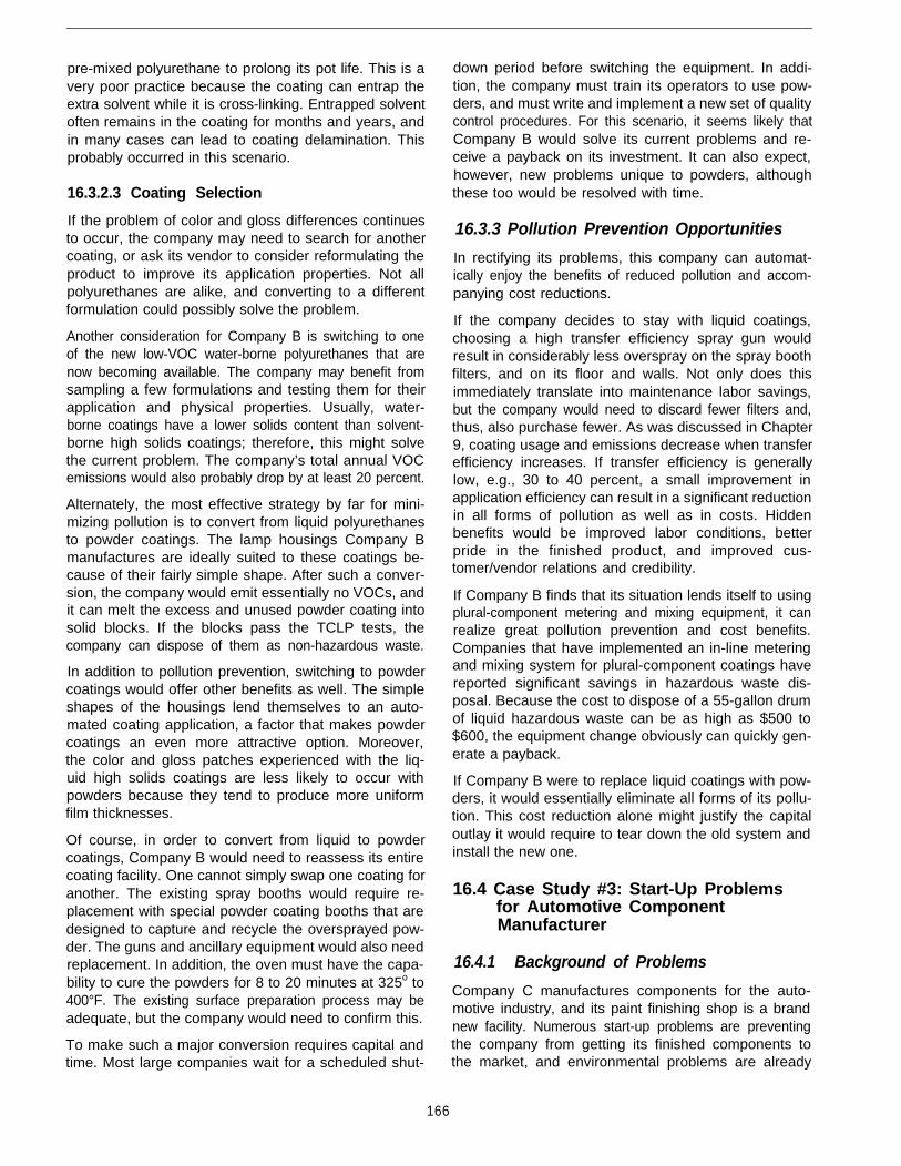
pre-mixed polyurethane to prolong its pot life. This is avery poor practice because the coating can entrap theextra solvent while it is cross-linking. Entrapped solventoften remains in the coating for months and years, andin many cases can lead to coating delamination. Thisprobably occurred in this scenario.
16.3.2.3 Coating Selection
If the problem of color and gloss differences continuesto occur, the company may need to search for anothercoating, or ask its vendor to consider reformulating theproduct to improve its application properties. Not allpolyurethanes are alike, and converting to a differentformulation could possibly solve the problem.
Another consideration for Company B is switching to oneof the new low-VOC water-borne polyurethanes that arenow becoming available. The company may benefit fromsampling a few formulations and testing them for theirapplication and physical properties. Usually, water-borne coatings have a lower solids content than solvent-borne high solids coatings; therefore, this might solvethe current problem. The company’s total annual VOCemissions would also probably drop by at least 20 percent.
Alternately, the most effective strategy by far for mini-mizing pollution is to convert from liquid polyurethanesto powder coatings. The lamp housings Company Bmanufactures are ideally suited to these coatings be-cause of their fairly simple shape. After such a conver-sion, the company would emit essentially no VOCs, andit can melt the excess and unused powder coating intosolid blocks. If the blocks pass the TCLP tests, thecompany can dispose of them as non-hazardous waste.
166
In addition to pollution prevention, switching to powdercoatings would offer other benefits as well. The simpleshapes of the housings lend themselves to an auto-mated coating application, a factor that makes powdercoatings an even more attractive option. Moreover,the color and gloss patches experienced with the liq-uid high solids coatings are less likely to occur withpowders because they tend to produce more uniformfilm thicknesses.
Of course, in order to convert from liquid to powdercoatings, Company B would need to reassess its entirecoating facility. One cannot simply swap one coating foranother. The existing spray booths would require re-placement with special powder coating booths that aredesigned to capture and recycle the oversprayed pow-der. The guns and ancillary equipment would also needreplacement. In addition, the oven must have the capa-bility to cure the powders for 8 to 20 minutes at 325o to400°F. The existing surface preparation process may beadequate, but the company would need to confirm this.
To make such a major conversion requires capital andtime. Most large companies wait for a scheduled shut-
down period before switching the equipment. In addi-tion, the company must train its operators to use pow-ders, and must write and implement a new set of qualitycontrol procedures. For this scenario, it seems likely thatCompany B would solve its current problems and re-ceive a payback on its investment. It can also expect,however, new problems unique to powders, althoughthese too would be resolved with time.
16.3.3 Pollution Prevention Opportunities
In rectifying its problems, this company can automat-ically enjoy the benefits of reduced pollution and accom-panying cost reductions.
If the company decides to stay with liquid coatings,choosing a high transfer efficiency spray gun wouldresult in considerably less overspray on the spray boothfilters, and on its floor and walls. Not only does thisimmediately translate into maintenance labor savings,but the company would need to discard fewer filters and,thus, also purchase fewer. As was discussed in Chapter9, coating usage and emissions decrease when transferefficiency increases. If transfer efficiency is generallylow, e.g., 30 to 40 percent, a small improvement inapplication efficiency can result in a significant reductionin all forms of pollution as well as in costs. Hiddenbenefits would be improved labor conditions, betterpride in the finished product, and improved cus-tomer/vendor relations and credibility.
If Company B finds that its situation lends itself to usingplural-component metering and mixing equipment, it canrealize great pollution prevention and cost benefits.Companies that have implemented an in-line meteringand mixing system for plural-component coatings havereported significant savings in hazardous waste dis-posal. Because the cost to dispose of a 55-gallon drumof liquid hazardous waste can be as high as $500 to$600, the equipment change obviously can quickly gen-erate a payback.
If Company B were to replace liquid coatings with pow-ders, it would essentially eliminate all forms of its pollu-tion. This cost reduction alone might justify the capitaloutlay it would require to tear down the old system andinstall the new one.
16.4 Case Study #3: Start-Up Problemsfor Automotive ComponentManufacturer
16.4.1 Background of Problems
Company C manufactures components for the auto-motive industry, and its paint finishing shop is a brandnew facility. Numerous start-up problems are preventingthe company from getting its finished components tothe market, and environmental problems are already
surfacing. Before introducing the problems, a brief back-ground of the facility’s process follows.
Several types of substrates require coating by this com-pany. The facility cleans and treats components madeof cold rolled steel in a 7-stage zinc phosphate linedesigned to give a heavy zinc phosphate coating of 400mg/ft2 to prevent corrosion. Alternately, operators treataluminum parts with a chromate conversion coating. Allmetal substrates then receive one coat of an epoxybasecoat. Operators then apply a clear coat of two-com-ponent polyurethane over the basecoat.
All plastic housings are scuff-sanded and washed witha mixture of methyl ethyl ketone (MEK) and isopropanolbefore being primed with an epoxy sanding primer.Thereafter, operators sand the primer to a smooth finishwith 240-grit to 400-grit paper to hide all swirl marks inthe plastic molding. The plastic parts then receive aconductive primer.
All of the spray booths in the facility are of the cross-draft, dry filter type. Operators change the filters as soonas the magnahelic gauges on the sides of the boothsshow a pressure differential of 0.5 inches. Becausecoating usage differs for each booth, the filters are notall changed at the same time.
One large finishing room contains all of the spraybooths. One very large air make-up unit supplies all ofthe air to the booths. Strict procedures prevent un-authorized employees from entering the finishing room.Those who do enter must wear cotton booties, lint-freecoveralls, and lint-free disposable caps to cover theirhair. In the booths, electrostatic turbo bells held byrobots or reciprocators actually apply the coatings.
The problems that need addressing are:
Heavy sludge from the zinc phosphate pretreatmenttank requires disposal of relatively large volumes ofwaste.
Large volumes of rinse water from the spray washerrequire treatment before being discharged to the pub-lically owned treatment works (POTW). In addition,the POTW is complaining because the facility wasnever designed to handle so much water, and is ask-ing Company C to urgently address this problem.
The finished steel components and aluminum partsdo not have the same gloss, even though they usethe same basecoat and clear coat. For some colors,the gloss difference also appears to the observer asa color difference. This is a major problem when steeland aluminum parts are adjacent to each other onthe same assembly.
Most finishes are marred with dust and dirt despitethe fact that all personnel wear clean lint-free clothing
and the company has made every effort to keep dustout of the finishing room.
Dry overspray mars some of the clear coats. Viewingthe parts under a microscope suggests that the over-spray may come from the basecoat booths.
Although the company uses electrostatic turbo bells,the transfer efficiency is too low for such guns. Con-sequently, VOC emissions already approach the per-mitted cap and are almost double what was originallyestimated when the permits were applied for. A con-sequence of the poorer than expected transfer effi-ciency is that the filters become clogged morefrequently and require disposal. Because the com-pany has determined that the overspray from at leastone of the coatings fails the TCLP test, the policy isto dispose of all the spent filters as solid hazardouswaste. In a typical month, the company disposes often 55-gallon drums of spent filters, and this signifi-cantly increases the total cost of running the paintshop.
16.4.2 Possible Solutions
Zinc phosphates do produce sludge, and this is one ofthe disadvantages that end-users must accept whenthey specify a zinc phosphate system. If the sludgebuild-up is higher than expected, then end-users mayneed to evaluate several operating parameters. For in-stance, causes for the high sludge build-up may include:
The concentration of the bath may be too high
The temperature may be too high
The tank may be over-agitated
Parts may be in the phosphating stage for too long
The pH may be incorrect
Company C should call its chemical supplier and ask atechnical representative to troubleshoot the problem.The supplier will probably find at least one of the pa-rameters out of specification. This implies that betterprocess controls may need to be in place, and operatorsmay need to monitor the parameters more frequently.
The large volumes of water the facility treats and dis-charges may be warranted, or they may be excessive.In order to assess this, the company must addressseveral questions:
Are the fabricated metal surfaces more contaminatedthan they should be? If so, how can the companyminimize their contamination loading?
Is the drag-out from the process tanks to the rinsetanks too high?
Has the rinse water overflow rate been correctly cal-culated?
167
l Is the company maintaining the concentration of therinse tanks at unrealistically low levels?
l Are the rinse tanks designed to achieve optimumcounter-flow characteristics?
l Why can’t the company treat and recycle the waterin a closed loop system?
The gloss differences between the steel and aluminumparts may result from a difference in the surface finishof the two metals or from the zinc phosphate coating.
If the two metals have different surface finishes, thecompany may need to specify a different finish, or if thatis not possible, operators can apply a sanding primer tothe rougher of the two metals. This option, however,would add significantly to the cost of the finishing proc-ess. Not only does it require an extra coat, but allcomponents would require sanding to a smooth finishbefore applying the basecoat.
Some zinc phosphates produce macro-crystals that ab-sorb the coating, thus giving the appearance of lowergloss. The automotive industry tends to purchase zincphosphates that produce micro-crystals. For such sys-tems, one would not expect to see a noticeable glossdifference between the steel and aluminum coated parts.
Keeping dust and dir-t out of a painting facility is ex-tremely difficult. In this scenario, the company has ap-parently taken precautions to keep the employees frombringing contaminants into the facility; therefore, otherpossible causes may be:
l The spray room may be operating under negativepressure.
l The air make-up unit may be pulling in dust-laden air.
l The coatings may contain dir-t that was not previouslyfiltered out.
If the spray room is at times operating under negativepressure, the vacuum can pull dust and dirt from adja-cent areas of the factory.
The air make-up unit, which has obviously been de-signed to pull a large volume of air into the spray room,may be pulling in dust-laden air from the exhaust stacksof other operations (specifically the sanding operation).If the intake filters to the air make-up unit have toocoarse a mesh, or if the pressure differential across thefilters is too high, the dust and dir-t could easily enter thespray room.
The possibility also exists, although it is less likely, thatthe coatings themselves contain dirt that was not filteredout prior to use. End-users can easily check this bytaking a spatula and dipping it into the pressure pot. Asthe paint runs off the end, one can spot small dirt parti-cles in the wet coating. If these particles are present,
using simple filtering techniques can usually solve theproblem.
The problem of overspray from one spray booth affect-ing the finishes in another booth may at first seembaffling. Bear in mind, however, that all of the spraybooths are dry filter booths. Thus, as each filter padcollects overspray, the pressure differential across thefilter bank increases, and the air flow into the exhauststack decreases accordingly. Since one air make-up unitfeeds all the booths, the air flow within the larger finish-ing room is constantly changing. Some filters becomemore plugged with overspray than others, pressure dif-ferentials constantly change, and air movement is neverconstant. As soon as operators change the contami-nated filters in one spray booth, this booth suddenlydraws its maximum capacity of air, which may entaildrawing air from another spray booth with clogged fil-ters. In addition, sometimes one or more booths may beidle for a few hours of the day. Then, as operators turnon the blowers, the booth suddenly draws air, onceagain changing the dynamics of the entire finishingroom.
The most effective method for eliminating this problemis to provide a separate air make-up system for eachbooth. This would ensure that the air make-up is alwayssufficient to supply the needed volume of air. If too muchof a positive pressure develops, however, the air wouldonce again start affecting other booths.
The problem of improper ventilation is not easy to solve,and the company may need to hire ventilation consult-ants to rethink the system.
The final issue for this company, transfer efficiency, isone of the most important parameters that affects VOCemissions into the air, as well as the volume of hazard-ous waste generated. Because electrostatic turbo bellsare known for their high efficiencies, the company mustlook at other factors that may be causing the problem.These include:
l Inconsistent air flow
l Improper grounding
The company has already established that the air flowin the finishing room is not laminar and changes direc-tion from one moment to the next. The efficiency of turbobells is extremely sensitive to air flow in the booth. Evenwhen air flow is (correctly) toward the filter bank, if thevelocity is too high, the air carries the paint particlesaway from the parts being painted and into the filters.
Alternately, if the parts are not properly grounded, or ifthe paint does not have the proper polarity, the turbobells cannot apply the coating electrostatically.
A few quick experiments can determine why the turbobells are not achieving the desired transfer efficiency.
168
Since this is a major factor affecting VOC emissions andhazardous waste, the company should investigate thisproblem to the fullest so that it can achieve the maxi-mum efficiency.
16.4.3 Pollution Prevention Opportunities
Pollution prevention opportunities for Company Cabound. First, if it could reduce the amount of solidsludge waste from the zinc phosphate treatment, whichis in itself a pollution prevention measure, the companywould also be extending the life of the bath. This wouldnecessarily reduce the total volume of water that Com-pany C needs to treat and dispose of occasionally.
If the company installs a closed loop system (i.e., bytreating all the effluent water from the treatment systemand then recycling it), its cost for city water would drop.No guarantee exists, however, that this would lead to anoverall cost reduction, particularly if the city tap water isinexpensive and the cost for in-house treatment is high.
The pollution prevention and cost benefits associatedwith overcoming the poor spray booth conditions and theinappropriate choice of spray guns are very similar tothose provided in Case Study #2.
If Company C can solve the critical problem of turbulentair flow in the spray booths, total air emissions wouldimmediately drop, as would the generation of unneces-sary hazardous waste, both in the form of used dry filtersand waste paint.
Clearly, the company has little choice but to resolve itsproblems if it wants to remain competitive and stay inbusiness. By solving its production problems, it will auto-matically enjoy many unexpected cost benefits, and it willdramatically improve the environment of the community.
16.5 Conclusion
This chapter has presented three typical scenarios. Allof them relate to day-to-day production problems in acoating facility, and to a large extent the problems havelittle to do directly with the environment. The suggestedsolutions, however, show that once a company imple-ments better management practices, the rate of reworksand rejects diminishes, as do the parameters that affectthe quantity of coatings and solvents used. It is a win-winsituation for all parties:
l The company enjoys fewer environmental/regulatoryproblems, more efficient processes, greater produc-tivity, greater competitiveness in the market, andlower finishing costs.
l The customer gets a higher quality product.
l We all enjoy dramatically reduced air, water, and wastepollution.
A reader who wants to keep updated with current coat-ing and equipment technologies can access manymonthly technical journals that are often available freeof charge. Some address the scientific community andare very technical. Alternately, other journals are solelypragmatic and target finishing engineers, paint supervi-sors, and painters who are looking for any hints that willmake their jobs easier.
Readers can often find in the literature solutions toproblems such as those this chapter has discussed.Failing that, the reader has access to chemical, coating,and equipment vendors. When the problem is too com-plex or crosses many different fields, consultants can beretained. The end-user can usually find one or moreavenues to resolve problems. As a consequence tosolving these production problems, the end-user will becontributing to pollution prevention.
169

Appendixes
171

Appendix ASelected List of Suppliers of Aqueous and Semi-aqueous Degreaser
Formulations and Equipment*
l Reproduced with permission from the Waste Reduction Resource Center for the South East, Raleigh, NC.
172
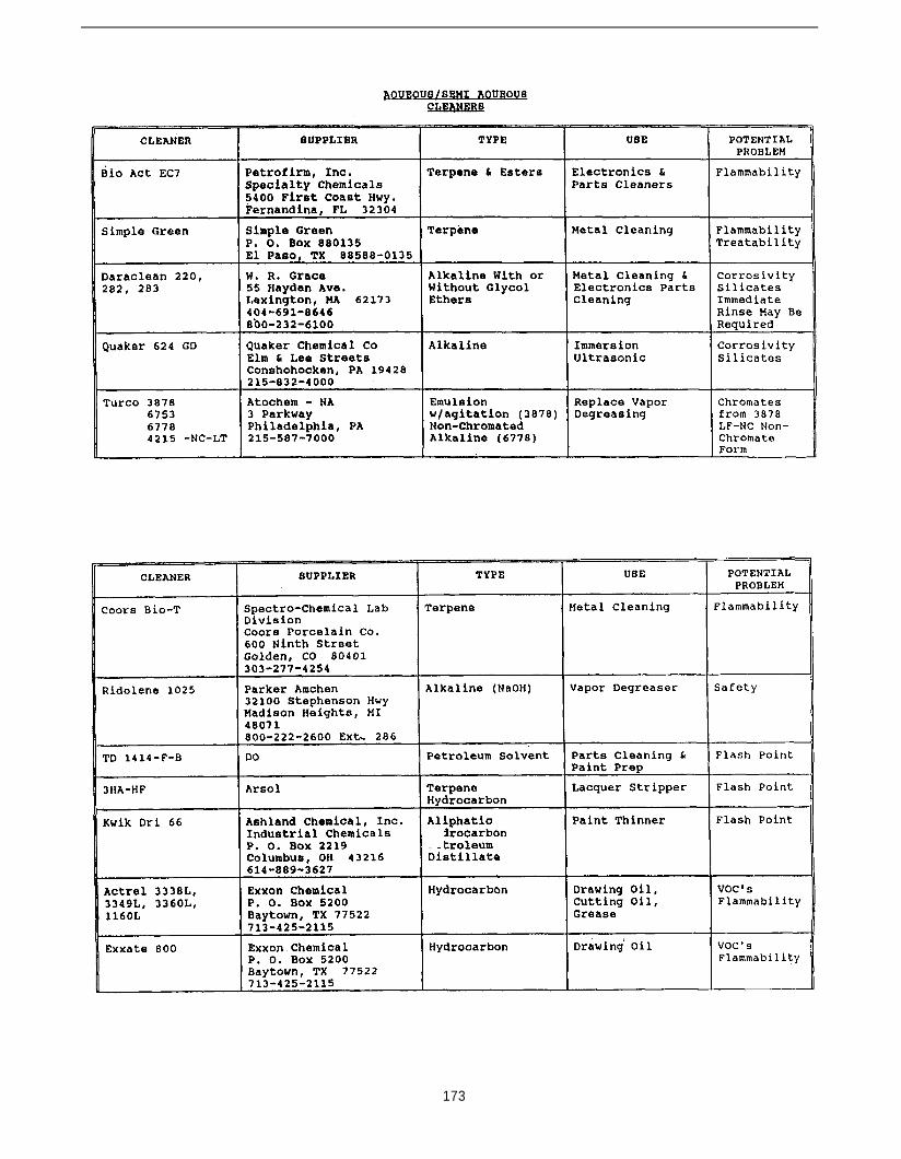
173

174

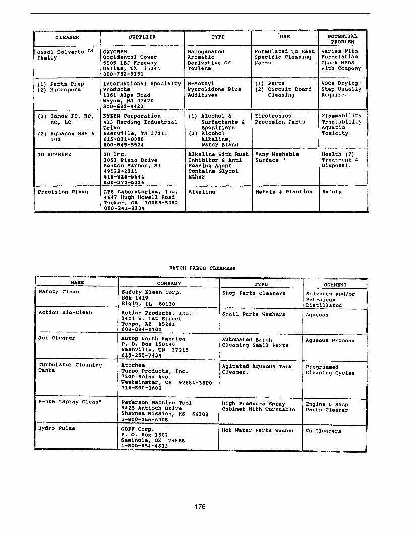

177
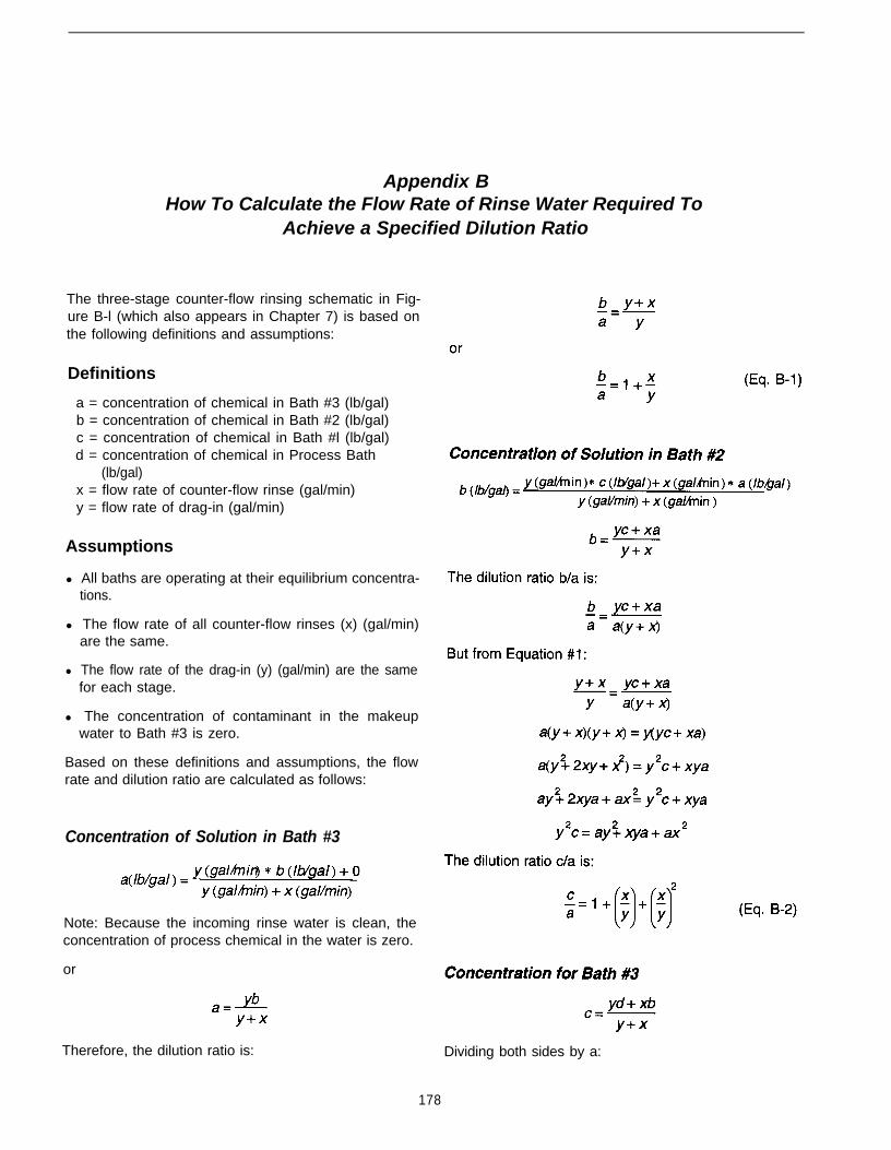
Appendix BHow To Calculate the Flow Rate of Rinse Water Required To
Achieve a Specified Dilution Ratio
The three-stage counter-flow rinsing schematic in Fig-ure B-l (which also appears in Chapter 7) is based onthe following definitions and assumptions:
Definitions
a = concentration of chemical in Bath #3 (lb/gal)b = concentration of chemical in Bath #2 (lb/gal)c = concentration of chemical in Bath #l (lb/gal)d = concentration of chemical in Process Bath
(lb/gal)x = flow rate of counter-flow rinse (gal/min)y = flow rate of drag-in (gal/min)
Assumptions
l All baths are operating at their equilibrium concentra-tions.
l The flow rate of all counter-flow rinses (x) (gal/min)are the same.
l The flow rate of the drag-in (y) (gal/min) are the samefor each stage.
l The concentration of contaminant in the makeupwater to Bath #3 is zero.
Based on these definitions and assumptions, the flowrate and dilution ratio are calculated as follows:
Concentration of Solution in Bath #3
Note: Because the incoming rinse water is clean, theconcentration of process chemical in the water is zero.
or
Therefore, the dilution ratio is: Dividing both sides by a:
178

179
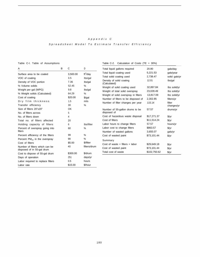
A p p e n d i x C
S p r e a d s h e e t M o d e l T o E s t i m a t e T r a n s f e r E f f i c i e n c y
Table C-l. Table of Assumptions Table C-2. Calculation of Costs (TE = 30%)
A B C D Total liquid gallons required
Total liquid coating used
Total solid coating used
Density of solid coating(Calculated)
20.80 gals/day
5,221.53 gals/year
2,738.47 solid gals/yr
12.01 Ibs/gal
Surface area to be coated
VOC of coating
Density of VOC portion
% Volume solids
Weight per gal (WPG)
% Weight solids (Calculated)
Cost of coating
D r y f i l m t h i c k n e s s
Transfer efficiency
Size of filters 20”x20”
No. of filters across
No. of filters down
Total no. of filters affected
Holding capacity of filters
Percent of overspray going intofilters
Percent efficiency of the filters
Percent PM10 in the overspray
Cost of filters
Number of filters which can bedisposed of in 55-gal drum
Cost to dispose of 55-gal drum
Days of operation
Labor required to replace filters
Labor rate
3,500.00
3.5
7.36
52.45
9.8
64.29
$20.00
1.5
30
OK
5
4
20
6
60
99
99
$5.00
40
$300.00
251
0.5
$15.00
ft2/day
Ibs/gal
Ibs/gal
%
Ibs/gal
%
$/galmils
%
Ibs/filter
%
%
%
$/filter
filters/drum
$/drum
days/yr
hours
$/hour
Weight of solid coating used 32,897.84
Weight of total solid overspray 23,028.49
Weight of solid overspray in filters 13,817.09
Number of filters to be disposed of 2,302.85
Number of filter changes per year 115.14
Number of 55-gallon drums to bedisposed of
57.57
Cost of hazardous waste disposal
Cost of filters
Labor hours to change filters
Labor cost to change filters
Number of wasted gallons
Cost of wasted paint
$17,271.37
$11,514.24
57.57
$863.57
3,655.07
$73,101.44
Summary
Cost of waste + filters + labor
Cost of wasted paint
Total cost of waste
$29,649.18
$73,101.44
$102,750.62
Ibs solid/yr
Ibs solid/yr
Ibs solid/yr
filters/yr
filterchanges/yr
drums/yr
$/yr
$/yrhours/yr
$/yr
gals/yr
$/yr
$/yr
$/yr
$/yr
1 8 0
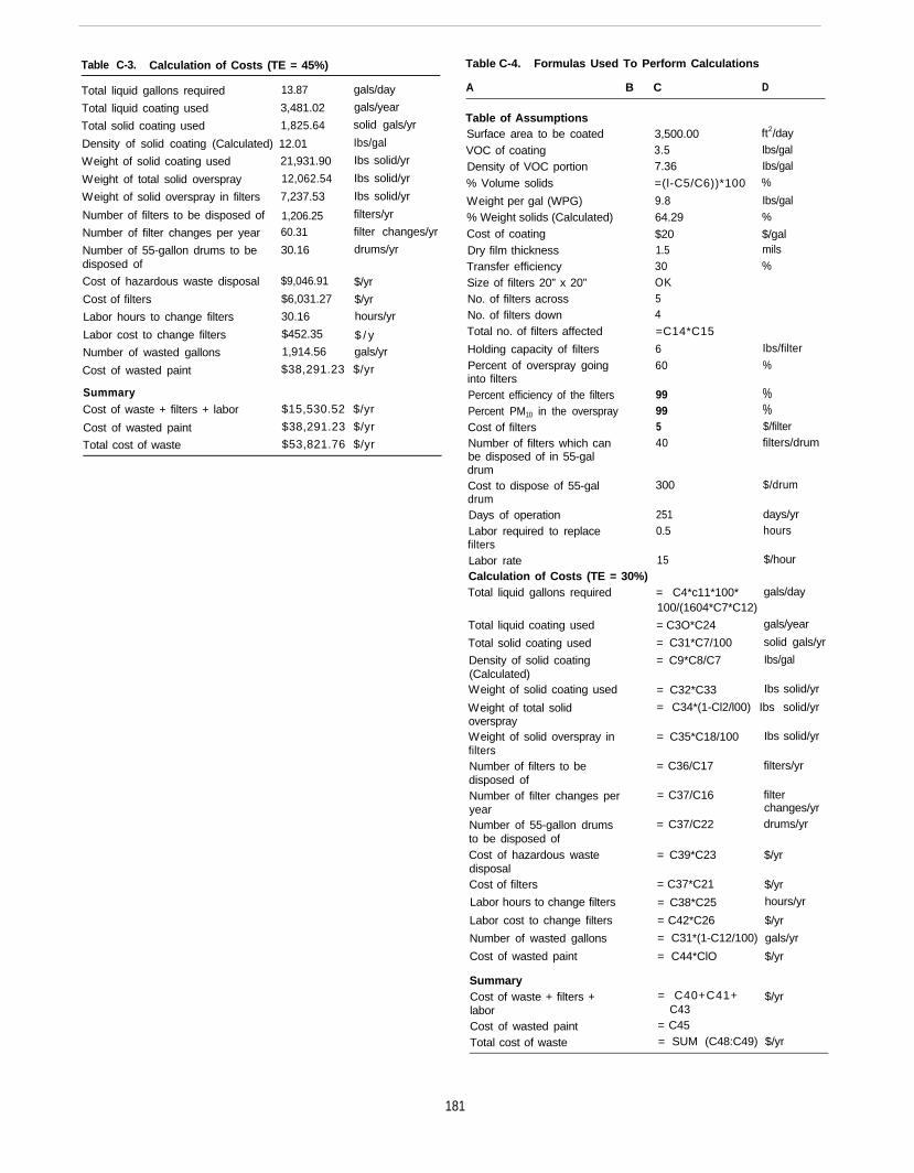
Table C-3. Calculation of Costs (TE = 45%)
Total liquid gallons required 13.87 gals/day
Total liquid coating used 3,481.02 gals/year
Total solid coating used 1,825.64 solid gals/yr
Density of solid coating (Calculated) 12.01 Ibs/gal
Weight of solid coating used 21,931.90 Ibs solid/yr
Weight of total solid overspray 12,062.54 Ibs solid/yr
Weight of solid overspray in filters 7,237.53 Ibs solid/yr
Number of filters to be disposed of 1,206.25 filters/yr
Number of filter changes per year 60.31 filter changes/yr
Number of 55-gallon drums to be 30.16 drums/yrdisposed of
Cost of hazardous waste disposal
Cost of filters
Labor hours to change filters
Labor cost to change filters
Number of wasted gallons
Cost of wasted paint
SummaryCost of waste + filters + labor
Cost of wasted paint
Total cost of waste
$9,046.91 $/yr
$6,031.27 $/yr
30.16 hours/yr
$452.35 $ / y1,914.56 gals/yr
$38,291.23 $/yr
$15,530.52 $/yr
$38,291.23 $/yr
$53,821.76 $/yr
Table C-4. Formulas Used To Perform Calculations
A B C D
Table of AssumptionsSurface area to be coatedVOC of coatingDensity of VOC portion% Volume solids
Weight per gal (WPG)% Weight solids (Calculated)Cost of coatingDry film thicknessTransfer efficiencySize of filters 20” x 20”No. of filters acrossNo. of filters downTotal no. of filters affected
Holding capacity of filtersPercent of overspray goinginto filtersPercent efficiency of the filtersPercent PM10 in the oversprayCost of filtersNumber of filters which canbe disposed of in 55-galdrumCost to dispose of 55-galdrumDays of operationLabor required to replacefiltersLabor rateCalculation of Costs (TE = 30%)Total liquid gallons required
Total liquid coating used
Total solid coating used
Density of solid coating(Calculated)Weight of solid coating used
Weight of total solidoversprayWeight of solid overspray infiltersNumber of filters to bedisposed ofNumber of filter changes peryearNumber of 55-gallon drumsto be disposed ofCost of hazardous wastedisposalCost of filters
Labor hours to change filters
Labor cost to change filters
Number of wasted gallons
Cost of wasted paint
SummaryCost of waste + filters +laborCost of wasted paintTotal cost of waste
3,500.003.57.36
=(l-C5/C6))*100
9.864.29
$201.530OK54
=C14*C15
660
99 %99 %5 $/filter40 filters/drum
300 $/drum
251 days/yr0.5 hours
15 $/hour
ft2/dayIbs/galIbs/gal%
Ibs/gal%
$/galmils%
Ibs/filter
%
= C4*c11*100* gals/day100/(1604*C7*C12)
= C3O*C24 gals/year
= C31*C7/100 solid gals/yr
= C9*C8/C7 Ibs/gal
= C32*C33 Ibs solid/yr
= C34*(1-Cl2/l00) Ibs solid/yr
= C35*C18/100 Ibs solid/yr
= C36/C17 filters/yr
= C37/C16 filterchanges/yr
= C37/C22 drums/yr
= C39*C23 $/yr
= C37*C21 $/yr
= C38*C25 hours/yr
= C42*C26 $/yr
= C31*(1-C12/100) gals/yr
= C44*ClO $/yr
= C40+C41+ $/yrC43
= C45= SUM (C48:C49) $/yr
181
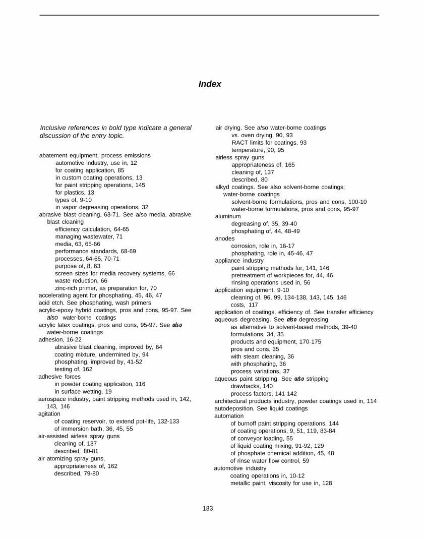
Index
Inclusive references in bold type indicate a generaldiscussion of the entry topic.
abatement equipment, process emissionsautomotive industry, use in, 12for coating application, 85in custom coating operations, 13for paint stripping operations, 145for plastics, 13types of, 9-10in vapor degreasing operations, 32
abrasive blast cleaning, 63-71. See a/so media, abrasiveblast cleaning
efficiency calculation, 64-65managing wastewater, 71media, 63, 65-66performance standards, 68-69processes, 64-65, 70-71purpose of, 8, 63screen sizes for media recovery systems, 66waste reduction, 66zinc-rich primer, as preparation for, 70
accelerating agent for phosphating, 45, 46, 47acid etch. See phosphating, wash primersacrylic-epoxy hybrid coatings, pros and cons, 95-97. See
also water-borne coatingsacrylic latex coatings, pros and cons, 95-97. See also
water-borne coatingsadhesion, 16-22
abrasive blast cleaning, improved by, 64coating mixture, undermined by, 94phosphating, improved by, 41-52testing of, 162
adhesive forcesin powder coating application, 116in surface wetting, 19
aerospace industry, paint stripping methods used in, 142,143, 146
agitationof coating reservoir, to extend pot-life, 132-133of immersion bath, 36, 45, 55
air-assisted airless spray gunscleaning of, 137described, 80-81
air atomizing spray guns,appropriateness of, 162described, 79-80
air drying. See a/so water-borne coatingsvs. oven drying, 90, 93RACT limits for coatings, 93temperature, 90, 95
airless spray gunsappropriateness of, 165cleaning of, 137described, 80
alkyd coatings. See also solvent-borne coatings;water-borne coatings
solvent-borne formulations, pros and cons, 100-10water-borne formulations, pros and cons, 95-97
aluminumdegreasing of, 35, 39-40phosphating of, 44, 48-49
anodescorrosion, role in, 16-17phosphating, role in, 45-46, 47
appliance industrypaint stripping methods for, 141, 146pretreatment of workpieces for, 44, 46rinsing operations used in, 56
application equipment, 9-10cleaning of, 96, 99, 134-138, 143, 145, 146costs, 117
application of coatings, efficiency of. See transfer efficiencyaqueous degreasing. See also degreasing
as alternative to solvent-based methods, 39-40formulations, 34, 35products and equipment, 170-175pros and cons, 35with steam cleaning, 36with phosphating, 36process variations, 37
aqueous paint stripping. See a/so strippingdrawbacks, 140process factors, 141-142
architectural products industry, powder coatings used in, 114autodeposition. See liquid coatingsautomation
of burnoff paint stripping operations, 144of coating operations, 9, 51, 119, 83-84of conveyor loading, 55of liquid coating mixing, 91-92, 129of phosphate chemical addition, 45, 48of rinse water flow control, 59
automotive industrycoating operations in, 10-12metallic paint, viscosity for use in, 128
183

paint stripping methods for, 141, 143, 146plural-component liquid coatings, use in, 92powder coatings, use in, 114rinsing operations, use in, 56, 61water-borne coatings, use in, 10zinc phosphating, use in, 47, 167
baffle spray booths, 158baking finishes. See also powder coatings; solvent-borne
coatings; water-borne coatingssolvent-borne formulations, pros and cons, 101-l 02water-borne formulations, pros and cons, 99-l 00
batch mixing of coatings, appropriateness of, 91, 92-93,126, 165
best management practicesfor abrasive blast cleaning, 69-70for aqueous degreasing, 37for equipment cleaning, 134-138for liquid coatings selection, 86for liquid-solvent degreasing, 33-34for phosphating, 45for rinsing, 55-56for semi-aqueous degreasing, 38for spray booth operations, 158-159for vapor degreasing, 30for viscosity management, 125-127, 129-133, 162
blast cleaning. See abrasive blast cleaningBrookfield viscometer, 124-125burnoff of paint coatings, 144-145
CAAA. See Clean Air Act Amendmentscabinet, abrasive blast cleaning, 65carbon dioxide pellet blasting, 146cathodes
corrosion, role in, 17phosphating, role in, 45-46, 47
cathodic protection, 18CFCs. See a/so methyl chloroform
degreasing generally, use in, 29vapor degreasing, use in, 30
chiller coils, use in vapor degreasing, 30, 31chilling
of coatings to extend pot-life, 126, 132-133of workpiece for paint stripping, 146
chlorinated solvents in paint stripping formulations, 140-141.See also solvents
chlorofluorocarbon-113. See CFCschromate-based sealing rinse formulations, 60-61chromate oxide
alternatives, nonchromate, 44for phosphating aluminum, 8, 44in water-borne epoxy coatings, 97, 98
Clean Air Act Amendments (CAAA)chemicals in coatings, regulation of, 135degreasing, relevance to, 29major source facilities, 32, 136paint stripping chemicals, regulation of, 141
cleaning of application equipment, 134-138cleaning formulation, 136fluid hoses, 138by paint stripping, 141, 143, 145, 146pressure pots, 137
regulation of solvent use in, 135-136spray guns, 137-138transfer efficiency, relevance for, 76
cleaning of workpieces, 28-29. See also degreasing;abrasive blast cleaning
coatingscoverage of, 74-85liquid, 85-113types of, 9
cohesive forces, in surface wetting, 19coil coating on raw materials, 24cold cleaning. See liquid-solvent degreasingcompliant coatings. See liquid coatingscomponent parts
protective coatings on, 24-25storage of, 25
computers, use in inventory control, 25. See a/so automationcondensation
in mixed coatings, 93, 132on substrate, 16in vapor degreasing, 30
contaminants, surface, 19-21abrasive blast cleaning of, 64on plastics, 21rinsing of, 53-59in tap water, 55testing for removal of, 50types of, 26-27
conversion coating. See phosphatingconveyors
automated loading, 55continuous operation, 163-l 64
copper, corrosion of, 17corrosion, galvanic
abrasive blast cleaning, removal by, 66caused by poor wetting, 19mechanisms of, 16-18phosphating for resistance to, 41-52protection of raw materials against, 23-25sealing rinses, resistance provided by, 59zinc phosphates, resistance provided by, 48zinc vs. iron phosphating, resistance provided by, 45,
47counter-flow rinsing
dilution ratio for, 57process calculations for, 58, 176-177process flow, 58process rates for, 59, 60purpose of, 57water usage in, 58
curingof baked on solvent-borne liquid coatings, 101-102of powder coatings, 114, 116, 117-118, 119for transfer efficiency assessment, 78-79of water-borne liquid coatings, 99-100
degreasing, 26-40abrasive blast cleaning after, 8-9, 70approach selection, 27-28aqueous methods, 34-38formulation characteristics, 49-50immersion, 28
184
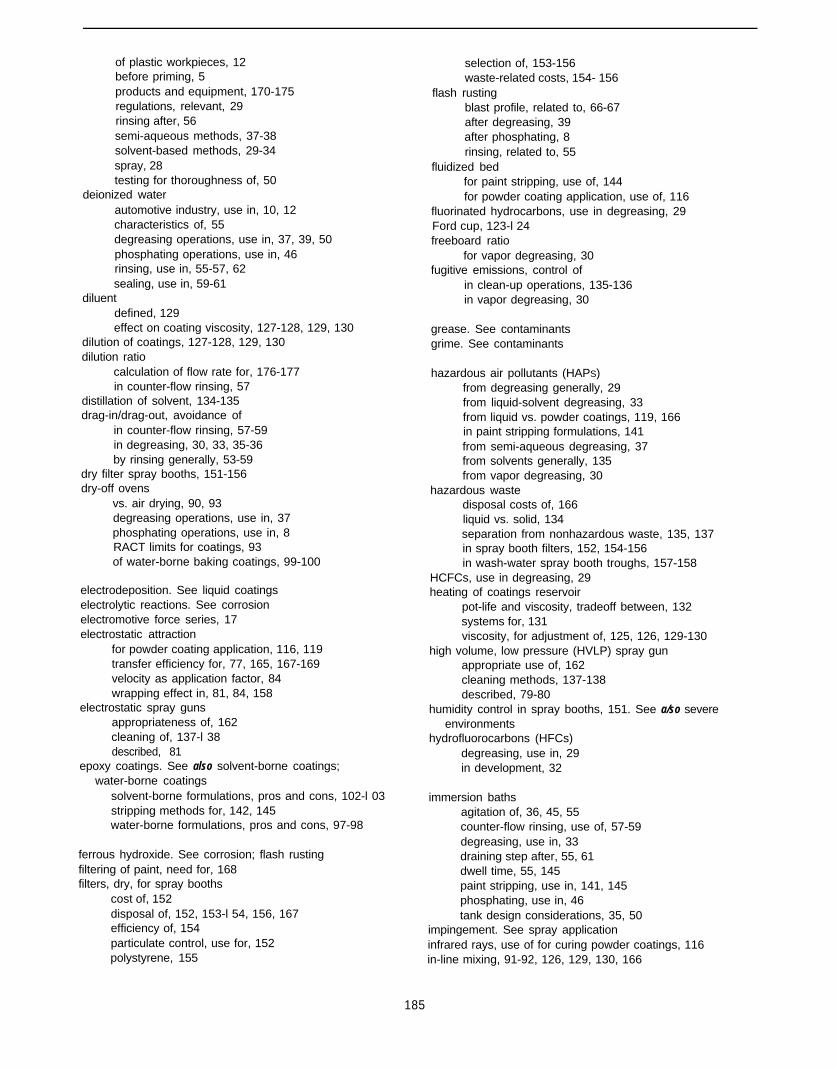
of plastic workpieces, 12before priming, 5products and equipment, 170-175regulations, relevant, 29rinsing after, 56semi-aqueous methods, 37-38solvent-based methods, 29-34spray, 28testing for thoroughness of, 50
deionized waterautomotive industry, use in, 10, 12characteristics of, 55degreasing operations, use in, 37, 39, 50phosphating operations, use in, 46rinsing, use in, 55-57, 62sealing, use in, 59-61
diluentdefined, 129effect on coating viscosity, 127-128, 129, 130
dilution of coatings, 127-128, 129, 130dilution ratio
calculation of flow rate for, 176-177in counter-flow rinsing, 57
distillation of solvent, 134-135drag-in/drag-out, avoidance of
in counter-flow rinsing, 57-59in degreasing, 30, 33, 35-36by rinsing generally, 53-59
dry filter spray booths, 151-156dry-off ovens
vs. air drying, 90, 93degreasing operations, use in, 37phosphating operations, use in, 8RACT limits for coatings, 93of water-borne baking coatings, 99-100
electrodeposition. See liquid coatingselectrolytic reactions. See corrosionelectromotive force series, 17electrostatic attraction
for powder coating application, 116, 119transfer efficiency for, 77, 165, 167-169velocity as application factor, 84wrapping effect in, 81, 84, 158
electrostatic spray gunsappropriateness of, 162cleaning of, 137-l 38described, 81
epoxy coatings. See also solvent-borne coatings;water-borne coatings
solvent-borne formulations, pros and cons, 102-l 03stripping methods for, 142, 145water-borne formulations, pros and cons, 97-98
ferrous hydroxide. See corrosion; flash rustingfiltering of paint, need for, 168filters, dry, for spray booths
cost of, 152disposal of, 152, 153-l 54, 156, 167efficiency of, 154particulate control, use for, 152polystyrene, 155
selection of, 153-156waste-related costs, 154- 156
flash rustingblast profile, related to, 66-67after degreasing, 39after phosphating, 8rinsing, related to, 55
fluidized bedfor paint stripping, use of, 144for powder coating application, use of, 116
fluorinated hydrocarbons, use in degreasing, 29Ford cup, 123-l 24freeboard ratio
for vapor degreasing, 30fugitive emissions, control of
in clean-up operations, 135-136in vapor degreasing, 30
grease. See contaminantsgrime. See contaminants
hazardous air pollutants (HAPS)from degreasing generally, 29from liquid-solvent degreasing, 33from liquid vs. powder coatings, 119, 166in paint stripping formulations, 141from semi-aqueous degreasing, 37from solvents generally, 135from vapor degreasing, 30
hazardous wastedisposal costs of, 166liquid vs. solid, 134separation from nonhazardous waste, 135, 137in spray booth filters, 152, 154-156in wash-water spray booth troughs, 157-158
HCFCs, use in degreasing, 29heating of coatings reservoir
pot-life and viscosity, tradeoff between, 132systems for, 131viscosity, for adjustment of, 125, 126, 129-130
high volume, low pressure (HVLP) spray gunappropriate use of, 162cleaning methods, 137-138described, 79-80
humidity control in spray booths, 151. See a/so severeenvironments
hydrofluorocarbons (HFCs)degreasing, use in, 29in development, 32
immersion bathsagitation of, 36, 45, 55counter-flow rinsing, use of, 57-59degreasing, use in, 33draining step after, 55, 61dwell time, 55, 145paint stripping, use in, 141, 145phosphating, use in, 46tank design considerations, 35, 50
impingement. See spray applicationinfrared rays, use of for curing powder coatings, 116in-line mixing, 91-92, 126, 129, 130, 166
185
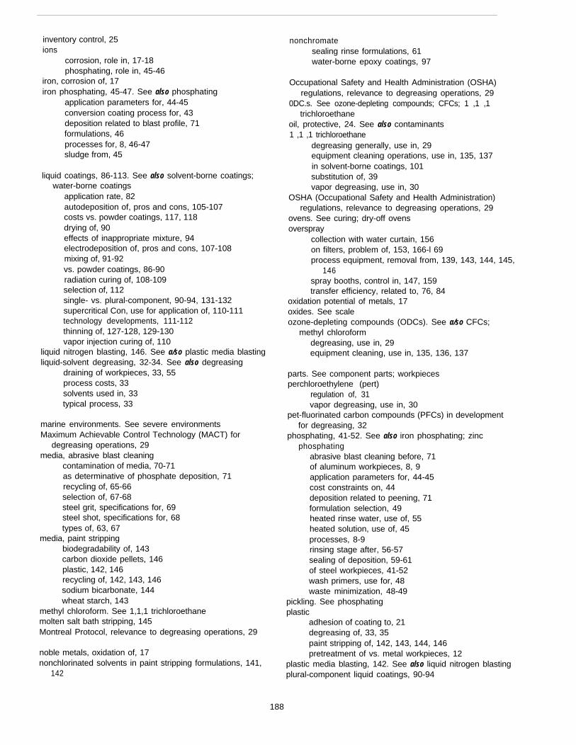
inventory control, 25ions
corrosion, role in, 17-18phosphating, role in, 45-46
iron, corrosion of, 17iron phosphating, 45-47. See also phosphating
application parameters for, 44-45conversion coating process for, 43deposition related to blast profile, 71formulations, 46processes for, 8, 46-47sludge from, 45
liquid coatings, 86-113. See also solvent-borne coatings;water-borne coatings
application rate, 82autodeposition of, pros and cons, 105-107costs vs. powder coatings, 117, 118drying of, 90effects of inappropriate mixture, 94electrodeposition of, pros and cons, 107-108mixing of, 91-92vs. powder coatings, 86-90radiation curing of, 108-109selection of, 112single- vs. plural-component, 90-94, 131-132supercritical Con, use for application of, 110-111technology developments, 111-112thinning of, 127-128, 129-130vapor injection curing of, 110
liquid nitrogen blasting, 146. See a/so plastic media blastingliquid-solvent degreasing, 32-34. See also degreasing
draining of workpieces, 33, 55process costs, 33solvents used in, 33typical process, 33
marine environments. See severe environmentsMaximum Achievable Control Technology (MACT) for
degreasing operations, 29media, abrasive blast cleaning
contamination of media, 70-71as determinative of phosphate deposition, 71recycling of, 65-66selection of, 67-68steel grit, specifications for, 69steel shot, specifications for, 68types of, 63, 67
media, paint strippingbiodegradability of, 143carbon dioxide pellets, 146plastic, 142, 146recycling of, 142, 143, 146sodium bicarbonate, 144wheat starch, 143
methyl chloroform. See 1,1,1 trichloroethanemolten salt bath stripping, 145Montreal Protocol, relevance to degreasing operations, 29
noble metals, oxidation of, 17nonchlorinated solvents in paint stripping formulations, 141,
142
nonchromatesealing rinse formulations, 61water-borne epoxy coatings, 97
Occupational Safety and Health Administration (OSHA)regulations, relevance to degreasing operations, 29
0DC.s. See ozone-depleting compounds; CFCs; 1 ,1 ,1trichloroethane
oil, protective, 24. See also contaminants1 ,1 ,1 trichloroethane
degreasing generally, use in, 29equipment cleaning operations, use in, 135, 137in solvent-borne coatings, 101substitution of, 39vapor degreasing, use in, 30
OSHA (Occupational Safety and Health Administration)regulations, relevance to degreasing operations, 29
ovens. See curing; dry-off ovensoverspray
collection with water curtain, 156on filters, problem of, 153, 166-l 69process equipment, removal from, 139, 143, 144, 145,
146spray booths, control in, 147, 159transfer efficiency, related to, 76, 84
oxidation potential of metals, 17oxides. See scaleozone-depleting compounds (ODCs). See a/so CFCs;
methyl chloroformdegreasing, use in, 29equipment cleaning, use in, 135, 136, 137
parts. See component parts; workpiecesperchloroethylene (pert)
regulation of, 31vapor degreasing, use in, 30
pet-fluorinated carbon compounds (PFCs) in developmentfor degreasing, 32
phosphating, 41-52. See also iron phosphating; zincphosphating
abrasive blast cleaning before, 71of aluminum workpieces, 8, 9application parameters for, 44-45cost constraints on, 44deposition related to peening, 71formulation selection, 49heated rinse water, use of, 55heated solution, use of, 45processes, 8-9rinsing stage after, 56-57sealing of deposition, 59-61of steel workpieces, 41-52wash primers, use for, 48waste minimization, 48-49
pickling. See phosphatingplastic
adhesion of coating to, 21degreasing of, 33, 35paint stripping of, 142, 143, 144, 146pretreatment of vs. metal workpieces, 12
plastic media blasting, 142. See also liquid nitrogen blastingplural-component liquid coatings, 90-94
188
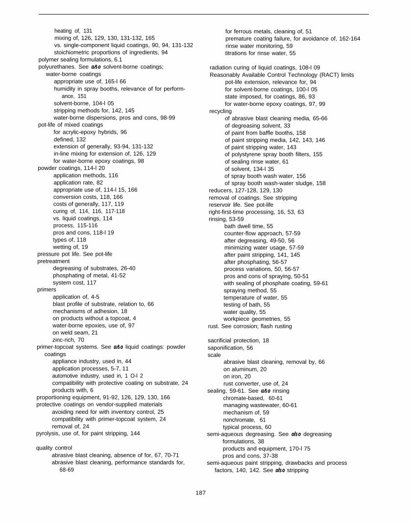
heating of, 131mixing of, 126, 129, 130, 131-132, 165vs. single-component liquid coatings, 90, 94, 131-132stoichiometric proportions of ingredients, 94
polymer sealing formulations, 6.1polyurethanes. See a/so solvent-borne coatings;
water-borne coatingsappropriate use of, 165-l 66humidity in spray booths, relevance of for perform-
ance, 151solvent-borne, 104-l 05stripping methods for, 142, 145water-borne dispersions, pros and cons, 98-99
pot-life of mixed coatingsfor acrylic-epoxy hybrids, 96defined, 132extension of generally, 93-94, 131-132in-line mixing for extension of, 126, 129for water-borne epoxy coatings, 98
powder coatings, 114-l 20application methods, 116application rate, 82appropriate use of, 114-l 15, 166conversion costs, 118, 166costs of generally, 117, 119curing of, 114, 116, 117-118vs. liquid coatings, 114process, 115-116pros and cons, 118-l 19types of, 118wetting of, 19
pressure pot life. See pot-lifepretreatment
degreasing of substrates, 26-40phosphating of metal, 41-52system cost, 117
primersapplication of, 4-5blast profile of substrate, relation to, 66mechanisms of adhesion, 18on products without a topcoat, 4water-borne epoxies, use of, 97on weld seam, 21zinc-rich, 70
primer-topcoat systems. See a/so liquid coatings: powdercoatings
appliance industry, used in, 44application processes, 5-7, 11automotive industry, used in, 1 O-l 2compatibility with protective coating on substrate, 24products with, 6
proportioning equipment, 91-92, 126, 129, 130, 166protective coatings on vendor-supplied materials
avoiding need for with inventory control, 25compatibility with primer-topcoat system, 24removal of, 24
pyrolysis, use of, for paint stripping, 144
quality controlabrasive blast cleaning, absence of for, 67, 70-71abrasive blast cleaning, performance standards for,
68-69
for ferrous metals, cleaning of, 51premature coating failure, for avoidance of, 162-164rinse water monitoring, 59titrations for rinse water, 55
radiation curing of liquid coatings, 108-l 09Reasonably Available Control Technology (RACT) limits
pot-life extension, relevance for, 94for solvent-borne coatings, 100-l 05state imposed, for coatings, 86, 93for water-borne epoxy coatings, 97, 99
recyclingof abrasive blast cleaning media, 65-66of degreasing solvent, 33of paint from baffle booths, 158of paint stripping media, 142, 143, 146of paint stripping water, 143of polystyrene spray booth filters, 155of sealing rinse water, 61of solvent, 134-l 35of spray booth wash water, 156of spray booth wash-water sludge, 158
reducers, 127-128, 129, 130removal of coatings. See strippingreservoir life. See pot-liferight-first-time processing, 16, 53, 63rinsing, 53-59
bath dwell time, 55counter-flow approach, 57-59after degreasing, 49-50, 56minimizing water usage, 57-59after paint stripping, 141, 145after phosphating, 56-57process variations, 50, 56-57pros and cons of spraying, 50-51with sealing of phosphate coating, 59-61spraying method, 55temperature of water, 55testing of bath, 55water quality, 55workpiece geometries, 55
rust. See corrosion; flash rusting
sacrificial protection, 18saponification, 56scale
abrasive blast cleaning, removal by, 66on aluminum, 20on iron, 20rust converter, use of, 24
sealing, 59-61. See a/so rinsingchromate-based, 60-61managing wastewater, 60-61mechanism of, 59nonchromate, 61typical process, 60
semi-aqueous degreasing. See also degreasingformulations, 38products and equipment, 170-l 75pros and cons, 37-38
semi-aqueous paint stripping, drawbacks and processfactors, 140, 142. See also stripping
187
severe environmentscoating durability in, 47, 49corrosion in, 20, 66-67storage of raw materials in, 24zinc-rich primers, use of, 70
single- vs. plural-component liquid coatings, 93, 94SIPS (State Implementation Plans), relevance to
degreasing, 29sludge
from aqueous degreasing, 35, 36, 50dewatering of, 157-l 58disposal of, 158generation relative to transfer efficiency, 76from iron vs. zinc phosphating, 45, 48from molten salt bath stripping, 145from phosphating, excess heavy metals in, 44, 48, 49from solvent-based paint stripping, 141, 142from solvent recycling, 135from spray booth filters, 154-l 55from spray booth wash water, 157
sodium bicarbonate wet blasting, 144solvent-based paint stripping. See also stripping
drawbacks, 140formulation, 140process factors, 141
solvent-borne coatings, 100-105. See also liquid coatingsalkyd, pros and cons, 100-101baked on, pros and cons, 101-l 02epoxy, pros and cons, 102-l 04hardness scale, 102polyurethane, 104-I 05spray viscosities, 127vs. water-borne coatings, 91, 92
solventsdefined, 129drying of during coating application, 159entrapment of in coatings, 165-l 66equipment cleaning, use in, 134-138high boiling points, with, 136paint stripping, use in, 139-142recycling of, 134-l 35thinning coatings, use for, 127, 129, 130, 165-166
solvent wiping. See a/so liquid-solvent degreasing .for degreasing, 33disposal of rags, 34toluene and xylene, use of, 34
South Coast Air Quality Management District (SCAQMD),California, 79, 80, 81, 136-137
spray booths, 147-l 59cleaning of, 134-l 38defined, 147dry filter type, pros and cons, 152-l 52enclosure, extent of, 149configurations in general, 10, 148-l 51custom coating operations, use in, 13lighting in, 159process management, 158-159temperature and humidity in, 151types of, 151-158
188
ventilation considerations, 149-l 51, 152, 153, 158, 159water-wash type, pros and cons, 156-l 57
spray application
for aqueous degreasing, 35,36of custom coatings, 13efficiency techniques, 81-85, 131equipment cleaning, 134-138gun types, 9, 79-81, 119for iron phosphating, 46for liquid solvent degreasing, 32-33of paint stripping formulation, 141for rinsing, 50-51, 55for semi-aqueous degreasing, 38,techniques, 149-150, 158, 159transfer efficiency factors for, 75-76, 79-81, 162of water after sealing rinse, 61
State Implementation Plans (SIPS), relevance todegreasing, 29
steelautodeposition of coatings on, 106corrosion of, 17, 55galvanized, 24, 48phosphate coating on, 41-52stainless, 24surface tension of, 19
storageflash rusting of materials in, 66, 70inventory control, 25sealing rinses on materials in, use of, 59of vendor-supplied materials, 24
stripping of coatings, 139-l 46alternative methods, pros and cons, 140-141, 142,
143, 143-144, 145, 146approaches, 139-l 40formulations for, 140mechanism of, 140, 141need for generally, 139solvent use for, 139temperature of formulations, 141
supercritical Con, use of for liquid coating application,110-111
surface preparationafter priming, 7steps in, 7-10for substrate, 64, 66of welded seam, 21
surface tensionof plastics, 21-22for semi-aqueous degreasers, 38of water, 20in wetting, 18-19
surfactantsapproach for removal from workpiece, 56in phosphating formulations, 46testing for removal of, 50wetting, role in, 19
tap water, municipalcharacteristics of, 55coating adhesion, as factor in, 57flushing application equipment, use for, 96rinsing, use in, 55, 56, 61, 145
Tape Adhesion Test, 162TCLP (Toxicity Characteristic Leaching Procedure) testing of
spray booth filters, 152-l 53, 167

thickness, coatingrelative to viscosity, 128, 164-l 66
thinning of liquid coatings, 127-128, 129, 13033/50 program, 118Title III Hazardous Air Pollutants. See Clean Air Act
Amendments; hazardous air pollutants (HAPS)Title V Permit Rule. See Clean Air Act Amendmentstowel-wipe test
after degreasing, 50Toxicity Characteristic Leaching Procedure (TCLP) testing of
spray booth filters, 152-l 53, 167transfer efficiency, 74-85
assessment approaches, 77-79benefits of improving, 74-77calculation of, 74, 76, 78, 79, 178-179cost of assessment, 78defined, 74filter selection for spray booth, factor in, 154, 155improvement approaches, 81-85for powder coatings, 119spray gun type, relative to, 79-81, 165
ultrafiltration of phosphating wastewater, 49
vapor injection curing. See liquid coatingsvapor-solvent degreasing, 29-32. See a/so degreasing
alternative solvents, 31-32types of solvents and boiling points, 31typical process, 31
vendor-supplied materials, 23-25ventilation of solvent degreasing vapors, 30, 34ventilation of spray booths, 149-151
calculation of, 151minimum requirements, 151problems with, 153, 158, 159, 168
viscosity, of liquid coatings, 121-133adjusted by thinning, 127-128, 129-130calculation of, 121-122control techniques, 125-127, 129-l 33defined, 121-l 22measurement technologies, 122-125of mixed coatings, 92, 132-133, 165for plural- vs. single-component, 131-l 32 .vs. pot-life with heating, 132problems associated with, 128-l 29, 164-I 66of solvent- vs. water-borne coatings, 127of thixotropic coatings, 122, 127of water-borne coatings, 98
volatile organic compounds (VOCs)limits on for drying coatings, 90, 93in liquid coatings generally, 90, 91paint stripping, emitted from, 141, 142-146in powder coatings, 114, 116, 119in primers, 5in solvent-borne coatings, 100-l 05spray booths, management with, 147, 166-l 69state monitoring of, 29state regulation of, 134, 136-137transfer efficiency, relative to, 76, 77, 167-169
in wash primers, 48in water-borne coatings, 94-100, 166
volume method of assessing transfer efficiency, 79
wastewaterfrom abrasive blast cleaning, 63, 71from degreasing, 36from liquid vs. powder coatings, 119from phosphating, treatment of, 49, 167-168from rinsing, minimizing, 57-59, 61-62from seal rinsing, chromate-based, 60-61from solvent-based paint stripping, 141in wash-water spray booth troughs, 157-l 58
water blasting, high- and medium-pressure, 143-l 44water-borne coatings, 94-100. See also liquid coatings
acrylic-epoxy hybrids, pros and cons, 95-97acrylic latex, pros and cons, 95-97alkyd, pros and cons, 95-97baked on, pros and cons, 99-100epoxy, pros and cons, 97-98humidity, control in spray booths when using, 151organic solvent (co-solvent) in, 95polyurethane dispersion, pros and cons, 98-99vs. solvent-borne coatings, 90, 91, 92thixotropic property of, 127types of, 95-98VOC content of, 94-100
water break-free test, use of after degreasing, 50water treatment in wash-water spray booths
methods, 157- 158selection of chemical, 157
water-wash spray booths, 156-l 58weight method for assessing transfer efficiency, 78-79weld slag and spatter, role of in corrosion, 21wetting, surface, role of in adhesion, 18-19wheat starch blasting, 142-l 43workpieces
of aluminum, 8, 9geometry relative to processing, 55, 119, 162of plastic vs. metal, 12size of relative to processing, 51, 63, 141size of relative to transfer efficiency, 79, 84size of relative to spray booth selection, 149, 158of steel, 41-52
Zahn cups, 122-I 23, 127zinc phosphating, 47-48. See also phosphating
conversion coating process, 43corrosion resistance provided by, 48mechanism of, 47as pretreatment, 8, 167process flow for, 11sludge from, 47, 48, 167spray application vs. immersion, 48titanium salt in rinse water, use of, 56
zinc, sacrificial use ofon Golden Gate Bridge, 18on raw materials, 24
189rU.S. COVERT P RINTING OFFICE: 1997-549-001/60155