polycomm fx usersguide
TRANSCRIPT
March 2003 Edition3725-21086-001A
ViewStation® FX/VS4000 User Guide
VS4000 User’s Guide
MarchMarchJune 2003 Edition3725-20097-005
Trademark Information
Polycom®, the Polycom logo design, and ViewStation® are registered trademarks of Polycom Inc. ARENA™, Global Management System™, PathNavigator™, Polycom OneDial™, and Visual Concert™ are trademarks of Polycom, Inc. in the United States and various other countries.
Internet Explorer™, NetMeeting®, Windows®, and Windows NT® are either registered trademarks or trademarks of Microsoft Corporation in the United States and/or other countries.
Intel®, Pentium®, and Celeron® are registered trademarks and TeamStation™ is a trademark of Intel Corporation.
Adobe® Acrobat® is a registered trademark of Adobe Systems Incorporated.
ADTRAN® is a registered trademark of ADTRAN, Inc.
QuickTime™ is a trademark of Apple Computer, Inc.
Netscape® Navigator® is a registered trademark of Netscape Communications Corporation.
IP/TV® is a registered trademark of Cisco Systems, Inc.
All other trademarks are the property of their respective owners. Every effort has been made to ensure that the information in this manual is accurate. Polycom, Inc. is not responsible for printing or clerical errors. Information in this document is subject to change without notice.
Patent Information
The accompanying product is protected by one or more U.S. and foreign patents and patents pending held by Polycom, Inc.
© 2003 Polycom, Inc. All rights reserved.
Polycom Inc.4750 Willow RoadPleasanton, CA 94588-2708USA
No part of this document may be reproduced or transmitted in any form or by any means, electronic or mechanical,for any purpose, without the express written permission of Polycom, Inc. Under the law, reproducing includes translating into another language or format.
As between the parties, Polycom, Inc. retains title to, and ownership of, all proprietary rights with respect to the software contained within its products. The software is protected by United States copyright laws and international treaty provision. Therefore, you must treat the software like any other copyrighted material (e.g. a book or sound recording).
Every effort has been made to ensure that the information in this manual is accurate. Polycom, Inc. is not responsiblefor printing or clerical errors. Information in this document is subject to change without notice.

© Polycom, Inc. 2003 i
Contents
Chapter 1 - Welcome to theViewStation FX/VS4000
Feature Highlights .....................................................................................................19What is in the Box? ....................................................................................................22
ViewStation FX.....................................................................................................22VS4000 ...................................................................................................................23Network Interface Module .................................................................................24Additional Information.......................................................................................25
Remote Control .............................................................................................25Microphone Pods..........................................................................................25Power Supply ................................................................................................26
Help and Technical Support .....................................................................................27Using Help............................................................................................................27Help Topics...........................................................................................................28Troubleshooting...................................................................................................28
General ...........................................................................................................28Audio..............................................................................................................30Video ..............................................................................................................31
How to Contact Technical Support ...................................................................31By Phone ........................................................................................................31By Internet .....................................................................................................32
Chapter 2 - Installing theViewStation FX/VS4000
What you Need to Install the ViewStation FX or VS4000 System ......................34Television Monitors.............................................................................................34Network Interfaces ..............................................................................................34
Ethernet ..........................................................................................................34ISDN ...............................................................................................................35
Power Source........................................................................................................36Integrated Cameras .............................................................................................36
Sony EVI-10 Camera ....................................................................................36Sony EVI-30 Camera ....................................................................................37
NT-1 Device ..........................................................................................................37Required Information..........................................................................................38
ViewStation FX/VS4000 User Guide
ii www.polycom.com
Equipment Installation .............................................................................................. 38Setting up the ViewStation FX........................................................................... 39Setting up the VS4000 ......................................................................................... 40ISDN Network Interface Modules .................................................................... 41
Setting up the V.35/RS-449/RS-530 Network Interface......................... 41Setting up the PRI Network Interface ....................................................... 44Setting up the Quad BRI Network Interface ............................................ 47
Optional Equipment ........................................................................................... 50Second Monitor ............................................................................................ 50Auxiliary Video Cameras............................................................................ 50VCR ................................................................................................................ 53Document Camera ....................................................................................... 54Visual Concert DC ....................................................................................... 54Visual Concert FX......................................................................................... 54ShowStation IP.............................................................................................. 55
Upgrading Software .................................................................................................. 57Upgrading Software over IP .............................................................................. 57Upgrading Software over ISDN (H.320).......................................................... 59
Updating System Software From a PC on a LAN ................................... 60Updating System Software Directly From a PC ...................................... 61Updating a System Already Loaded With the Current System Software64Updating System Software Remotely ....................................................... 66
Chapter 3 - Initial System SetupFirst System Screens .................................................................................................. 71
Selecting the Language....................................................................................... 71Selecting Menu Items with the Remote Control ............................................. 72Setting up System Name and Country............................................................. 73
System Name ................................................................................................ 73Country.......................................................................................................... 74
Setting your Call Preferences............................................................................. 74OneDial Preferences............................................................................................ 75
Initial Setup for IP (H.323) Calls .............................................................................. 76Setup for IP (H.323) Calls ................................................................................... 76Setting up a Gatekeeper ..................................................................................... 77
Initial Setup for ISDN (H.320) Calls ........................................................................ 80Setup for the V.35/RS-449/RS-530 Network Interface.................................. 80
Setting Video Network Options................................................................. 81Selecting Dialing Speeds ............................................................................. 82Setting Broadcast Mode Options ............................................................... 82Setting Advanced Dialing Preferences...................................................... 83Entering V.35/RS-449/RS-530 Video Numbers ...................................... 85

Contents
© Polycom, Inc. 2003 iii
Setup for the PRI Network Interface.................................................................86Entering PRI Video Numbers (E1 - T1) .....................................................86Setting up Line Signaling and Switch Protocols for E1...........................87Setting up PRI Options for T1.....................................................................88
Setup for the Quad BRI Network Interface......................................................89Entering ISDN Video Numbers..................................................................90Entering Service Profile Ids Manually.......................................................90Selecting the ISDN Switch Protocol ...........................................................91
Final Out-of-Box System Setup Screens ..................................................................93Configuring for Outside Line Calls...................................................................93Adding a Telephone Number ............................................................................94Setting up the VS4000 Camera...........................................................................94Setting the Administrator and Meeting Passwords........................................95
Setting up the Firewall ...............................................................................................96Verifying Initial Setup ...............................................................................................97
Placing a Test Call................................................................................................97Checking the Network Connectivity Indicators on the Main Screen...........97
Network Line Check Indicators .................................................................98ISDN Line Check Indicators .......................................................................98Gatekeeper Status Indicators ......................................................................99
Chapter 4 - Advanced Configuration for your Network Environment
Configuration of the LAN Settings .........................................................................103Configuring LAN and Intranet Settings...........................................................103Selecting Advanced LAN Settings ....................................................................107Configuring Firewall and LAN Connection Settings ....................................109
Configuration for IP (H.323) Calls ...........................................................................111Configuring H.323 Name and Extension .........................................................112Selecting Dialing Speeds.....................................................................................113Configuring the Gateway and Gatekeeper ......................................................114
Overview .......................................................................................................114About Polycom OneDial..............................................................................115Setting the Gateway and Gatekeeper ........................................................116Configuring the Gateway Number ............................................................118Selecting your Gateway Prefix and Suffix ................................................119
Configuration for ISDN (H.320) Calls .....................................................................121Advanced V.35/RS-449/RS-530 Network Interface Configuration.............121
Configuring the V.35/RS-449/RS-530 Serial Interface Control Signals122Setting up Satellite (H.331) Broadcast Mode ............................................123Selecting Dialing Speeds..............................................................................125Setting the Calling Profile............................................................................126
ViewStation FX/VS4000 User Guide
iv www.polycom.com
Enabling Crypto Resync.............................................................................. 128Advanced PRI Network Interface Configuration........................................... 129
Entering PRI Video Numbers..................................................................... 130Accessing PRI Information (T1 and E1) .................................................... 131Setting up PRI Options (T1 and E1)........................................................... 132Selecting PRI Channels (E1 and T1) .......................................................... 134Setting Advanced PRI Options (E1 and T1) ............................................. 136Setting Audio Quality Preference .............................................................. 138Choosing the Number of Channels to be Dialed in Parallel.................. 139Selecting Dialing Speeds ............................................................................. 140
Advanced Quad BRI Network Interface Configuration................................ 141Entering ISDN Video Numbers ................................................................. 141Entering or Detecting Service Profile Ids.................................................. 142Setting Audio Quality Preference .............................................................. 144Setting Channel Dialing Preferences ......................................................... 145Selecting Dialing Speeds ............................................................................. 146Modifying ISDN Video Network Information ........................................ 147
Configuration of the Global Address Book .......................................................... 148Overview .............................................................................................................. 148About the Global Address Book ....................................................................... 149Configuring Settings for the Global Address Book Server ........................... 149Setting the Global Address Book Preferences ................................................. 150Selecting your Preferred Alias........................................................................... 152Selecting the Call Type Order for OneDial Address Book Entries .............. 153Entering the Private Network Number............................................................ 154Establishing Dialing Rules ................................................................................. 154
Dialing Rules 1.............................................................................................. 154Dialing Rules 2.............................................................................................. 157
Configuration for the Global Management System .............................................. 159Overview .............................................................................................................. 159About Global Management System.................................................................. 159Setting Global Management Preferences ......................................................... 161Accessing Global Management Server URLs.................................................. 162Adding Global Management Technical Support Contact Information....... 163
Configuring Streaming Preferences ........................................................................ 165Configuring SNMP Preferences ............................................................................... 167Configuring Quality of Service ............................................................................... 169
Chapter 5 - Using the ViewStation FX/VS4000
Remote Control ........................................................................................................... 172Video Calls .................................................................................................................. 176

Contents
© Polycom, Inc. 2003 v
Placing a Call Manually ......................................................................................176Using One Number ......................................................................................176Using Two Numbers ....................................................................................179
Placing a Call from the Address Book..............................................................181Placing a Speed-Dial Call....................................................................................182Placing a Call from the Web Interface ..............................................................183Placing a Call Using the Application Programming Interface......................183Answering a Video Call Manually....................................................................183Answering a Video Call Automatically ...........................................................184Setting the System to Do Not Disturb...............................................................184Ending a Video Call.............................................................................................185
Analog Telephone Calls ............................................................................................186Placing a Telephone Call ....................................................................................186Adding a Telephone Call to a Video Call.........................................................187Disconnecting a Telephone Call ........................................................................187Adding a Video Call to a Telephone Call.........................................................188
Address Book ..............................................................................................................189Adding an Entry to the Address Book .............................................................190Editing an Existing Entry in the Address Book...............................................191Deleting Entries in the Address Book...............................................................192Transferring the Address Book..........................................................................192Using the Global Address Book.........................................................................193Creating Multipoint Address Book Entries .....................................................194
Cameras and Sound ...................................................................................................195Controlling Cameras ...........................................................................................195
Selecting a Near-Site Camera......................................................................195Selecting a Far-Site Camera.........................................................................196Controlling the Near-Site Camera..............................................................197Controlling the Far-Site Camera.................................................................197Adjusting a Second Camera........................................................................198Adjusting Camera Settings..........................................................................199Setting Camera Presets ................................................................................199Enabling Automatic Voice Tracking (ViewStation FX Only).................200Enabling Automatic Tracking to Camera Presets (ViewStation FX Only)201
Controlling Sound ...............................................................................................202Setting the Volume .......................................................................................202Using the Mute Button.................................................................................202Controlling Sound Effects Volume ............................................................203
Snapshots ....................................................................................................................204Sending Snapshots...............................................................................................204Snapshot Timeout ................................................................................................204
Picture-In-Picture (PIP) .............................................................................................206Graphics Cursor .........................................................................................................207
General Information ............................................................................................207

ViewStation FX/VS4000 User Guide
vi www.polycom.com
Using the Graphics Cursor................................................................................. 208
Chapter 6 - Using Advanced System FeaturesMultipoint Calls ......................................................................................................... 211
Before you Begin.................................................................................................. 211Multipoint Dialing Speed Table................................................................. 211Mixed Protocol Dialing Speed Table......................................................... 212Multipoint Downspeeding ......................................................................... 213Downspeeding/Resynchronization Compatibility ................................ 214Multipoint Calls and Firewall Information .............................................. 215
Placing Multipoint Video Calls ......................................................................... 216Using the Manual Dialer (Video Phone)................................................... 216Using an Address Book Meeting Entry .................................................... 218Using the Address Book.............................................................................. 220Using the Manual Dialer and the Address Book..................................... 220
Mixed Protocol Dialing....................................................................................... 221Different Ways to Place a Mixed Protocol Call........................................ 221Additional Information ............................................................................... 222
Multipoint Viewing Modes................................................................................ 223Mode Description......................................................................................... 223Switching Modes.......................................................................................... 225
Multipoint Conference Password ..................................................................... 226Setting Up the Meeting Password ............................................................. 226Using the Meeting Password...................................................................... 226MCU Meeting Password Protection in Multipoint Dial-In Calls.......... 228
Multipoint Cascading Capabilities ................................................................... 230Four-Monitor Support ........................................................................................ 230Chair Control ....................................................................................................... 231
General Information .................................................................................... 231Actions Available to All Sites ..................................................................... 232Actions Only Available to the Chair Controller ...................................... 233
Dial-In Calling ............................................................................................................ 234Dial-In Calling Scenarios.................................................................................... 234
With an Existing Point-to-Point Call ......................................................... 234With no Existing Point-to-Point Call......................................................... 235
Auto Answer Multipoint Mode Configuration .............................................. 235Setting the Auto Answer Multipoint Mode ............................................. 236
Conference on Demand (COD) ............................................................................... 237Implementation of Conference on Demand .................................................... 237COD User Interface Screens............................................................................... 238
Multipoint Call Screen................................................................................. 238Video Phone Screen ..................................................................................... 238

Contents
© Polycom, Inc. 2003 vii
Gatekeeper Screen ........................................................................................239Streaming Video .........................................................................................................240
Enabling Streaming .............................................................................................240Configuring Streaming Options ........................................................................241Configuring Streaming for Apple QuickTime ................................................242
Enabling and Starting Streaming on the ViewStation FX or VS4000....242Viewing Streaming with Apple QuickTime on the PC...........................242
Data Conferencing .....................................................................................................244Enabling Data Conferencing on your System ..........................................245Using a ShowStation IP ...............................................................................245Using Microsoft NetMeeting ......................................................................245
People+Content...........................................................................................................246
Chapter 7 - Using the System with a PCBefore you Begin .........................................................................................................248
PC Requirements .................................................................................................248Connecting the PC and the ViewStation FX or the VS4000 to the LAN......248Connecting the PC Directly to a ViewStation FX or a VS4000 not on the LAN
251Configuring your Web Browser ........................................................................253
Internet Explorer Configuration.................................................................253Netscape Configuration...............................................................................254
Accessing the Web Interface .....................................................................................256Features of the Web Interface ...................................................................................257
Placing a Call ........................................................................................................257Placing a Call from the Address Book.......................................................259Placing a Call from the Global Address Book..........................................259Placing a Call Using the Manual Dialer ....................................................259
Loading and Selecting a Slide Presentation.....................................................260Loading a Slide Presentation on the PC ....................................................261Selecting a Slide Presentation on the ViewStation FX or VS4000..........263Slide Display Information ...........................................................................266
Viewing a Slide Presentation .............................................................................266Viewing a Meeting...............................................................................................268Closed Caption.....................................................................................................268
Accessing and Using Closed Caption........................................................269Additional Information About Closed Caption.......................................269
PC-Resident Applications .........................................................................................271PolycomSnap........................................................................................................271NetMeeting ...........................................................................................................273
Enabling NetMeeting on the ViewStation FX or VS4000........................274Accessing NetMeeting .................................................................................274

ViewStation FX/VS4000 User Guide
viii www.polycom.com
Information About Placing an IP Video Calls with NetMeeting .......... 275Polycom Management Access Control Wizard (PMAC)............................... 276
Installing a Logo........................................................................................... 277Creating Custom Speed Dial and Custom Video Numbers Screens.... 277Creating the Management Password ........................................................ 278Password-Protecting Individual Screens.................................................. 279Connecting to and Disconnecting from your System............................. 280Open and Save Profiles ............................................................................... 280
System Setup and Remote Management ................................................................ 281Admin Setup/General Setup............................................................................. 282System Diagnostics ............................................................................................. 283
System Diagnostics ...................................................................................... 283Virtual Remote Control ............................................................................... 284Send a Message............................................................................................. 285Call Detail Report (CDR)............................................................................. 286
Streaming .................................................................................................................... 289
Chapter 8 - TroubleshootingGeneral ........................................................................................................................ 292Audio ........................................................................................................................... 293Video ........................................................................................................................... 295Network and Communications ............................................................................... 297IMUX ........................................................................................................................... 299LAN/Intranet ............................................................................................................. 300Presentations .............................................................................................................. 301Remote Control .......................................................................................................... 303
Appendix A - Screen ReferenceSystem Information Reference.................................................................................. 306Diagnostics Screen Reference .................................................................................. 308
Network Statistics................................................................................................ 308Advanced Network Statistics ............................................................................ 309
About Polycom Video Error Concealment™ (PVEC)............................. 310Call Status............................................................................................................. 311Color Bars ............................................................................................................. 311Audio..................................................................................................................... 312
Generate Tone............................................................................................... 312Audio Meter.................................................................................................. 313
Near End Loop..................................................................................................... 313Far End Loop........................................................................................................ 314

Contents
© Polycom, Inc. 2003 ix
Reset System .........................................................................................................314User Setup Screen Reference ....................................................................................315Admin Setup Screen Reference ................................................................................319
General Setup .......................................................................................................320V.35/RS-449/RS-530 Video Network Screens.................................................321
Multipoint Setup...........................................................................................322Call Preferences.............................................................................................322Video Network..............................................................................................322Dialing Speeds ..............................................................................................322Broadcast Mode ............................................................................................322Advanced Dialing.........................................................................................323Video Numbers.............................................................................................323Advanced V.35..............................................................................................323
PRI Video Network Screens ...............................................................................323IMUX (Inverse Multiplexer)........................................................................323PRI Video Numbers .....................................................................................323PRI Network..................................................................................................324PRI Information ............................................................................................324PRI Setup........................................................................................................324Advanced PRI Setup ....................................................................................324PRI Status.......................................................................................................324Audio Quality ...............................................................................................324Advanced Dialing.........................................................................................324Dialing Speeds ..............................................................................................324Call Preference ..............................................................................................325Multipoint Setup...........................................................................................325Dialing Speeds ..............................................................................................325
BRI Video Network Screens ...............................................................................325IMUX (Inverse Multiplexer)........................................................................325ISDN Video Numbers ..................................................................................325Auto Detect SPIDs ........................................................................................325Audio Quality ...............................................................................................326Advanced Dialing.........................................................................................326Dialing Speeds ..............................................................................................326Call Preferences.............................................................................................326Multipoint Setup...........................................................................................326ISDN Video Network...................................................................................326
LAN Setup Screens ..............................................................................................326LAN & Intranet (main) ................................................................................327LAN & Intranet (Configuration) ................................................................327Advanced LAN Settings..............................................................................327Firewall & LAN Connection .......................................................................327H.323 Setup (main) .......................................................................................327H.323 Setup (configuration) ........................................................................327
ViewStation FX/VS4000 User Guide
x www.polycom.com
Dialing Speeds .............................................................................................. 327Gateway & Gatekeeper................................................................................ 328Gateway Number......................................................................................... 328Gateway Setup.............................................................................................. 328Streaming....................................................................................................... 328SNMP Setup.................................................................................................. 328Global Address (Main) ................................................................................ 328Global Address (Server) .............................................................................. 328Global Address Book Preferences.............................................................. 328Preferred Alias.............................................................................................. 329Advanced Address Book Preferences ....................................................... 329Private Network ISDN (PRI) Number ...................................................... 329Dialing Rules 1.............................................................................................. 329Dialing Rules 2.............................................................................................. 329Global Management (Main)........................................................................ 329Global Management (Configuration)........................................................ 329Global Management URLs.......................................................................... 329Global Management Info ............................................................................ 330Quality of Service ......................................................................................... 330
Data Conference .................................................................................................. 330Telephone & Audio............................................................................................. 332Video and Cameras Screens............................................................................... 333
Monitors ........................................................................................................ 333TV Monitors .................................................................................................. 334Graphics Monitor ......................................................................................... 335FX VGA Monitor .......................................................................................... 337Cameras (FX) ................................................................................................ 337Cameras (VS4000) ........................................................................................ 338VCR Setup ..................................................................................................... 340VGA Input Calibration................................................................................ 341
Security ................................................................................................................. 342Crypto Resync Pulse ........................................................................................... 343Software and Hardware Screens....................................................................... 343
Software......................................................................................................... 344RS-232............................................................................................................. 344Hardware Information ................................................................................ 344Send Address Book...................................................................................... 345Far Site Software Update ............................................................................ 345
Appendix A - Interoperability InformationH.320 Endpoint Interoperability .............................................................................. 347H.323 Endpoint Interoperability .............................................................................. 348

Contents
© Polycom, Inc. 2003 xi
MCU H.320 Interoperability......................................................................................349MCU H.323 Interoperability......................................................................................349Gateway/Gatekeeper/T120 Server Interoperability .............................................350Firewall/NAT Interoperability.................................................................................351
Appendix A - ViewStation FX and VS4000 Technical Specifica-tions
ViewStation FX Technical Specifications.................................................................353VS4000 Technical Specifications ...............................................................................360
Appendix A - Security FeaturesSecurity Screens...........................................................................................................368
Admin and Meeting Password Screen .............................................................368Security Screen .....................................................................................................368
PMAC Security Features............................................................................................369Creating the Management Password................................................................370Password-Protecting Individual Screens .........................................................371
Security Features and Enhancements ......................................................................372Password for pcPresent (PowerPoint slides) ...................................................372Digest Implementation .......................................................................................372Adtran 512.............................................................................................................372Disabling Mixed Protocols .................................................................................373Telnet and FTP Timeout .....................................................................................373

ViewStation FX/VS4000 User Guide
xii www.polycom.com

© Polycom, Inc. 2003 xiii
List of Figures
Figure 1-1.Help Screen (Main)............................................................................................. 27Figure 1-2.Help Screen (Topics) .......................................................................................... 28Figure 2-1.ViewStation FX with Sony EVI-30 Camera..................................................... 37Figure 2-2.V.35/RS-449/RS-530 Network Interface Module (P-LINK side) ................ 42Figure 2-3.V.35/RS-449/RS-530 Network Interface Module (NETWORK side) ......... 43Figure 2-4.PRI Network Interface Module (P-LINK side)............................................... 45Figure 2-5.PRI Network Interface Module (NETWORK side)........................................ 46Figure 2-6.Quad BRI Network Interface Module (P-LINK side).................................... 48Figure 2-7.Quad BRI Network Interface Module (Network side).................................. 49Figure 2-8.Sony EVI-D100 and Sony EVI-D30 Cameras.................................................. 51Figure 2-9.PowerCam Camera ............................................................................................ 51Figure 2-10.Softupdate Screen ............................................................................................. 58Figure 2-11.Softupdate System Info Screen ....................................................................... 59Figure 3-1.Welcome (Language) Screen............................................................................. 71Figure 3-2.How to Select Menu Items Screen.................................................................... 72Figure 3-3.System Name Screen.......................................................................................... 73Figure 3-4.Country Screen.................................................................................................... 74Figure 3-5.H.323 Setup Screen ............................................................................................. 76Figure 3-6.Video Network Screen ....................................................................................... 81Figure 3-7.Dialing Speeds Screen........................................................................................ 82Figure 3-8.Advanced Dialing Screen .................................................................................. 83Figure 3-9.Advanced Dialing Screen (Calling Profile List) ............................................. 84Figure 3-10.Video Numbers Screen .................................................................................... 85Figure 3-11.PRI Video Numbers Screen............................................................................. 86Figure 3-12.PRI Setup Screen (for E1)................................................................................. 87Figure 3-13.PRI Setup Screen (for T1)................................................................................. 88Figure 3-14.ISDN Video Numbers Screen ......................................................................... 90Figure 3-15.Auto Detect SPIDs Screen ............................................................................... 91Figure 3-16.ISDN Switch Protocol Screen.......................................................................... 91Figure 3-17.Outside Line Calls Screen................................................................................ 93Figure 3-18.Telephone Numbers Screen ............................................................................ 94Figure 3-19.VS4000 Camera Setup Screen ......................................................................... 94Figure 3-20.ViewStation FX / VS4000 Main Screens ....................................................... 98Figure 3-21.Main Screen (showing network conditions)................................................. 99Figure 4-1.LAN & Intranet Screen .................................................................................... 104Figure 4-2.Advanced LAN Settings Screen ..................................................................... 107Figure 4-3.Firewall & LAN Connection Screen............................................................... 109Figure 4-4.H.323 Setup Screen (configuration) ............................................................... 112

ViewStation FX/VS4000 User Guide
xiv www.polycom.com
Figure 4-5.Dialing Speeds Screen ......................................................................................113Figure 4-6.Gateway & Gatekeeper Screen........................................................................116Figure 4-7.Gateway Number Screen .................................................................................118Figure 4-8.Gateway Screen .................................................................................................119Figure 4-9.Advanced V.35 Screen......................................................................................122Figure 4-10.Video Network Screen and Broadcast Mode Screens................................124Figure 4-11.Dialing Speeds Screen ....................................................................................125Figure 4-12.Advanced Dialing Screen (Page 1) ...............................................................127Figure 4-13.Advanced Dialing Screen (Calling Profile List)..........................................127Figure 4-14.Crypto Resync Pulse Screen ..........................................................................128Figure 4-15.PRI Information (E1) Screen ..........................................................................131Figure 4-16.PRI Setup (E1) and PRI Setup (T1) Screens .................................................132Figure 4-17.PRI Status (T1) and PRI Status (E1) Screens................................................134Figure 4-18.Advanced PRI Setup Screen ..........................................................................136Figure 4-19.Audio Quality Preference Screen..................................................................139Figure 4-20.Advanced Dialing Screen...............................................................................139Figure 4-21.Dialing Speeds Screen ....................................................................................140Figure 4-22.ISDN Video Numbers Screen........................................................................142Figure 4-23.Auto Detect SPIDs Screen ..............................................................................143Figure 4-24.Audio Quality Preference Screen..................................................................145Figure 4-25.Advanced Dialing Screen...............................................................................145Figure 4-26.Dialing Speeds Screen ....................................................................................146Figure 4-27.Global Address (Server) Screen ....................................................................150Figure 4-28.Global Address Book Preferences Screen (for IP and ISDN Calls) ..........151Figure 4-29.Dialing Rules 1 Screen ....................................................................................156Figure 4-30.Dialing Rules 2 Screen ....................................................................................157Figure 4-31.Global Management (Setup) Screen .............................................................161Figure 4-32.Global Management URLs Screen ................................................................163Figure 4-33.Global Management Info Screen...................................................................164Figure 4-34.Streaming Screen.............................................................................................165Figure 4-35.SNMP Setup Screen ........................................................................................167Figure 4-36.Quality of Service Screen ...............................................................................169Figure 5-1.Remote Control..................................................................................................173Figure 5-2.Video Phone Screen ..........................................................................................176Figure 5-3.Call Progress Indicators ...................................................................................178Figure 5-4.Call Hangup Choices Screen ...........................................................................178Figure 5-5.Address Book Screen ........................................................................................181Figure 5-6.Speed Dial Screen..............................................................................................182Figure 5-7.Telephone Screen ..............................................................................................186Figure 5-8.Address Book Screen ........................................................................................189Figure 5-9.Add/Change Entry Screen ..............................................................................190Figure 5-10.Local Video Sources........................................................................................195Figure 5-11.Camera Control Button on Remote Control................................................197Figure 6-1.Cascading 10 Sites in a Multipoint Call .........................................................230
© Polycom, Inc. 2003 xv
Figure 6-2.Chair Control Screen........................................................................................ 232Figure 6-3.Gatekeeper Screen ............................................................................................ 239Figure 6-4.Streaming Screen .............................................................................................. 240Figure 6-5.Data Conference Screen................................................................................... 244Figure 7-1.LAN & Intranet Screen .................................................................................... 249Figure 7-2.Placing a Video Call Web Screen ................................................................... 258Figure 7-3.pcPresent Screen ............................................................................................... 262Figure 7-4.pcPresent: File Open Screen............................................................................ 263Figure 7-5.Available Presentations Screen....................................................................... 264Figure 7-6.Presentation Password Screen ........................................................................ 264Figure 7-7.Presentation Directory (showing Loaded Slides) Screen............................ 265Figure 7-8.View a Meeting Web Screen .......................................................................... 268Figure 7-9.PolycomSnap Interface .................................................................................... 272Figure 7-10.General Setup Web Screen ............................................................................ 282Figure 7-11.System Diagnostics Web Screen................................................................... 284Figure 7-12.Web Interface Call Detail Report screen (partial view) ............................ 286Figure 7-13.Streaming Web Screen ................................................................................... 289Figure A-1.User Setup Screen............................................................................................ 315Figure A-2.Admin Setup Screen........................................................................................ 319Figure A-3.Data Conference Screen.................................................................................. 331Figure A-4.Telephone & Audio Screen ............................................................................ 332Figure A-5.TV Monitors Screen......................................................................................... 334Figure A-6.Graphics Monitor Screen................................................................................ 336Figure A-7.VS4000 Camera Setup Screen ........................................................................ 339Figure A-8.VCR Setup Screen............................................................................................ 340Figure A-9.VGA Input Calibration Screen....................................................................... 341

ViewStation FX/VS4000 User Guide
xvi www.polycom.com

© Polycom, Inc. 2003 xvii
List of Tables
Table 1-1.Key features of the ViewStation FX and VS4000 systems .............................. 19Table 4-1.Dialing rules used by the Global Address Book............................................ 155Table 5-1.Remote Control Functionality .......................................................................... 173Table 5-2.Graphic cursor function and remote control.................................................. 208Table 6-1.Multipoint Dialing Speeds ................................................................................ 211Table 6-2.Mixed Protocol Dialing Speeds ........................................................................ 213Table 6-3.Firewall TCP/UDP Ports in Multipoint Calls................................................ 215Table 6-4.MCU Meeting Password Protection ................................................................ 228Table 6-5.Dial-In Calling with an Existing Point-to-Point Call..................................... 235Table 6-6.Dial-In Calling with no Existing Point-to-Point Call .................................... 235Table 7-1.Password Usage with PMAC ........................................................................... 279Table B-1.H.320 Endpoint Interoperability...................................................................... 347Table B-2H.323 Endpoint Interoperability....................................................................... 348Table B-3.MCU H.320 Interoperability............................................................................. 349Table B-4.MCU H.323 Interoperability............................................................................. 349Table B-5.Gateway/Gatekeeper/T120 Server Interoperability.................................... 350Table B-6.Firewall/NAT Interoperability........................................................................ 351Table C-1.ViewStation FX Technical Specifications ....................................................... 353Table C-2.VS4000 Technical Specifications...................................................................... 360Table D-1.Password Usage with PMAC .......................................................................... 370

ViewStation FX/VS4000 User Guide
xviii www.polycom.com

© Polycom, Inc. 2003 17
1Welcome to the
ViewStation FX/VS4000
The ViewStation FX system is an easy-to-use, yet powerful set-top, network appliance that provides the clearest audio and video in the videoconferencing industry. The ViewStation FX group videoconferencing system (this includes the VS4000 system) was designed to provide the highest video communication performance for conference rooms, boardrooms, classrooms and custom conferencing facilities.
Note
Throughout this manual, the word “system” refers to both the ViewStation FX and VS4000 systems.
Topics in This Chapter
The following topics are included in this chapter.
Topic Description Page
Feature Highlights
This is an overview of the ViewStation FX and VS4000 systems’ main features and benefits..
19

ViewStation FX/VS4000 User Guide
18 www.polycom.com
What is in the Box?
This section lists the contents of the ViewStation FX and VS4000 shipping container.
22
Help and Technical Support
This section describes how to use the system Help screen and how to contact Technical Support.
27
Topic Description Page

Chapter 1 - Welcome to the ViewStation FX/VS4000
© Polycom, Inc. 2003 19
Feature Highlights
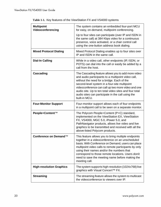
The following table provides a summary of the ViewStation FX and VS4000 systems’ main features and benefits.Refer also to the ViewStation FX and VS 4000 Technical Specifications in Appendix D for additional information. The ViewStation FX and VS4000 systems are functionally identical. The difference is that the VS4000 system is a rack-mounted videoconferencing unit that does not have a built-in camera.
Note
The VS4000 system supports four cameras; the camera input can be S-video or composite.
Table 1-1. Key features of the ViewStation FX and VS4000 systems
Feature Description
Video The ViewStation FX and VS4000 systems deliver TV quality video for lifelike conferencing interaction while fully supporting the H.263 video standard and the new 60 fields/ second ITU standard..
Audio The system provides clear 360 degree, full-duplex, digital audio with noise suppression, switchable echo cancellation and automatic gain control, as well as customized audio—extended audio flexibility via dual microphone pods and line-level audio input for custom microphones/mixers.
Camera Support Supports dual pan-tilt-zoom cameras, a VCR and document camera input, including support for the Visual Concert™ DC.
Network Flexibility The system supports the Quad BRI, PRI T1, PRI E1, V.35/RS-449/RS-530, and Ethernet network interfaces up to 2 Mbps.
ViewStation FX/VS4000 User Guide
20 www.polycom.com
Multipoint Videoconferencing
The system contains an embedded four-port MCU for easy, on-demand, multipoint conferencing.
Up to four sites can participate (over IP and ISDN in the same call) at 384 Kbps video for a continuous presence, voice activated, or a chair control call using the one-button address book dialing.
Mixed Protocol Dialing Mixed Protocol Dialing enables up to four sites over IP and ISDN in the same call.
Dial-In Calling While in a video call, other endpoints (IP, ISDN, or POTS) can dial into the call or easily be added by a call from the host.
Cascading The Cascading feature allows you to add more video and audio participants to a multipoint video call, without the need for a bridge. Each of the second-level system in a four-site multipoint videoconference can call up two more video and one audio site. Up to ten total video sites and four total audio sites can participate in the call using the built-in MCU.
Four-Monitor Support Four-monitor support allows each of four endpoints in a multipoint call to be seen on a separate monitor.
People+Content™ The Polycom People+Content (P+C) standard, implemented on the ViewStation EX, ViewStation FX, VS4000, MGC 5.0, iPower 5.0, and PathNavigator products, allows live video and live graphics to be transmitted and received with all the above-listed Polycom products.
Conference on Demand™ This feature allows you to bring multiple endpoints together in a videoconference on an unscheduled basis. With Conference on Demand, users can place multipoint video calls to remote participants by only using their names and/or the numbers that correspond to those remote locations. Users donít need to save the meeting name before making the meeting call.
High-resolution Graphics The system supports high-resolution (1024x768) live graphics with Visual Concert™ FX.
Streaming The streaming feature allows the system to multicast the videoconference to viewers over IP.
Table 1-1. Key features of the ViewStation FX and VS4000 systems

Chapter 1 - Welcome to the ViewStation FX/VS4000
© Polycom, Inc. 2003 21
Public and Private Networks The system supports both public and private networks through ISDN BRI, ISDN PRI, V.35/RS-449/RS-530, and Ethernet networks.
Web Management With embedded Web capabilities and remote management, IT managers can perform diagnostics and software upgrades.
Dual 10/100 Mbps Ethernet Ports
Through the dual 10/100 Mbps Ethernet port you can make IP calls, connect PCs, and allow Global Management System™ access and management.
Table 1-1. Key features of the ViewStation FX and VS4000 systems
ViewStation FX/VS4000 User Guide
22 www.polycom.com
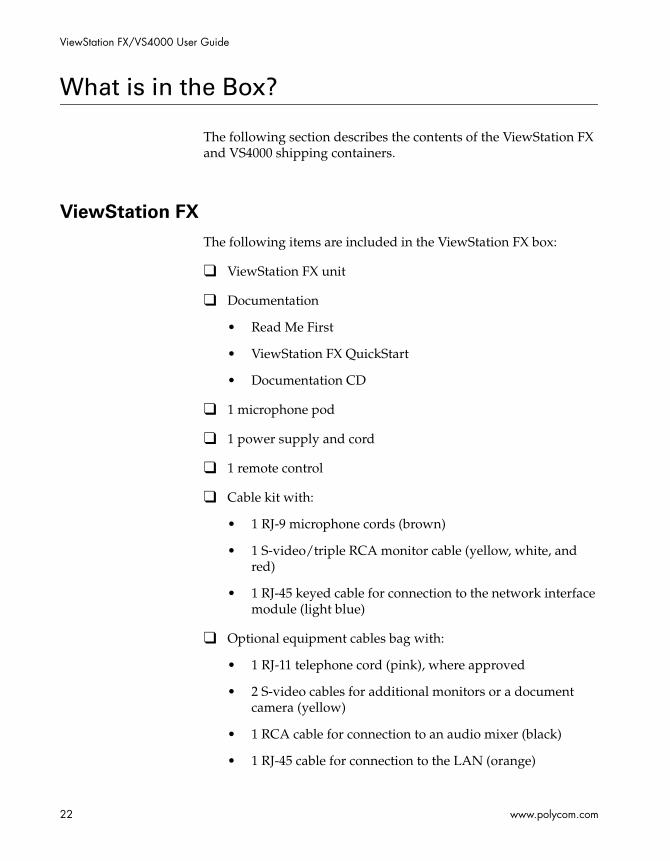
What is in the Box?
The following section describes the contents of the ViewStation FX and VS4000 shipping containers.
ViewStation FX
The following items are included in the ViewStation FX box:
❑ ViewStation FX unit
❑ Documentation
• Read Me First
• ViewStation FX QuickStart
• Documentation CD
❑ 1 microphone pod
❑ 1 power supply and cord
❑ 1 remote control
❑ Cable kit with:
• 1 RJ-9 microphone cords (brown)
• 1 S-video/triple RCA monitor cable (yellow, white, and red)
• 1 RJ-45 keyed cable for connection to the network interface module (light blue)
❑ Optional equipment cables bag with:
• 1 RJ-11 telephone cord (pink), where approved
• 2 S-video cables for additional monitors or a document camera (yellow)
• 1 RCA cable for connection to an audio mixer (black)
• 1 RJ-45 cable for connection to the LAN (orange)

Chapter 1 - Welcome to the ViewStation FX/VS4000
© Polycom, Inc. 2003 23
• 1 RJ-45 cable for connection to a PC (blue)
• 2 triple RCA cables for connection to a VCR (yellow, white, and red)
• 1 DB-15 XGA cable for connection to an additional monitor or projector
• 1 DB-9 serial port cable for connection to a touch panel 1 pan/tilt/zoom camera cable
VS4000
The following items are included in the VS4000 box:
❑ Read Me First
❑ VS4000 QuickStart
❑ VS4000 unit
❑ 2 rack-mount brackets with screws
❑ 2 microphone pods
❑ 1 power cord
❑ 2 remote controls
❑ 1 remote control infrared (IR) detector
❑ 1 network interface module (If you ordered the H.323 version of the VS4000, you do not receive a network interface module.)
❑ Monitor cables bag with:
• 4 S-video cables (yellow)
• 4 single RCA cables (yellow)
• 1 DB-15 XGA cable for connection to an additional monitor or projector
❑ Video cables bag with:
• 3 S-video cables (yellow)

ViewStation FX/VS4000 User Guide
24 www.polycom.com
• 3 single RCA cables (yellow)
❑ Serial/audio cables bag with:
• 1 DB-9 serial port cable for connection to a touch panel device
• 2 pan/tilt/zoom camera cables
• 2 triple RCA cables for connection to a VCR (yellow, white, and red)
• 1 RCA cable for connection to an audio mixer (black)
• 1 double RCA cable
❑ RJ cables bag with:
• 2 RJ-9 microphone cords (brown)
• 1 RJ-45 keyed cable for connection to the network interface module (light blue)
• RJ-11 telephone cord (pink), where approved
• 1 RJ-45 cable for connection to the LAN (orange)
• 1 RJ-45 cable for connection to a PC (blue)
Network Interface Module
The system may also include one of the following network interface equipment(s) (as specified by the user):
❑ V.35/RS-449/RS-530 network interface:
• V.35/RS-449/RS-530 module
❑ PRI network interface:
• PRI module
• Cables (1 RJ-45, 1 power supply cable)
❑ Quad BRI network interface:
• Quad BRI Inverse Multiplexer (IMUX)
Chapter 1 - Welcome to the ViewStation FX/VS4000
© Polycom, Inc. 2003 25
• 4 RJ-45 cables
• 1 RJ-45 cable with a keyed connector
Additional Information
The following provides important information about essential components of the system: the remote control, the microphone pods, and the power supply.
Remote Control
The remote control is an integral part of the system. You can use the remote control to configure and operate your system. Once you have the system set up and running, press the yellow INFO button on the remote control for a basic description of the remote control buttons.
For more information about the remote control, refer to Remote Control on page 172.
Microphone Pods
The microphone pods provide digital audio input to the system.
Each microphone pod has an audio range of approximately 30 feet (9-meters) and provides automatic gain control, noise suppression, and echo cancellation. You can press the MUTE button on the microphone to silence your end of the call. When the MUTE button is lighted, your end of the call is muted.
A second microphone pod provides enhanced audio pickup for all ViewStation models, except the ViewStation SP. Your system supports a maximum of two microphone pods daisy-chained together.
To connect the microphone pods to the system:
1. Connect the 30-foot (9-meter) cable to the system and one of the microphones pods.

ViewStation FX/VS4000 User Guide
26 www.polycom.com
2. Connect the 10-foot (3-meter) cable between the two microphone pods.
Note
Connecting and disconnecting the microphones does not require a reboot of the system.
Power Supply
The ViewStation FX system has an external power supply and the VS4000 system has an internal power supply. They support line voltages between 100V and 240V or line frequencies from 47 Hz to 63 Hz.
Note
You void the warranty and may possibly damage your system if you do not use the provided power supply.

Chapter 1 - Welcome to the ViewStation FX/VS4000
© Polycom, Inc. 2003 27
Help and Technical Support
This section provides information about using the on-screen help, basic troubleshooting, and contacting Polycom Technical support
Using Help
To access the Help screen:
Press the INFO button on the remote control. If your system is registered with a Global Management System, the following Help screen appears.
Figure 1-1. Help Screen (Main)

ViewStation FX/VS4000 User Guide
28 www.polycom.com
Help Topics
To access the Help screen:
Click the Help icon.
Figure 1-2. Help Screen (Topics)
Select the appropriate help topic from this screen. The topics provide assistance with basic system usage.
Troubleshooting
This section contains basic troubleshooting information. For more detailed information, refer to the Troubleshooting chapter.
General
Following are the most-often encountered problems and their solutions.
Remote control is not working.
Make sure the batteries are installed. Make sure you are pointing the remote control at the system’s IR detector. If battery power is low, a low battery icon appears on the main screen.

Chapter 1 - Welcome to the ViewStation FX/VS4000
© Polycom, Inc. 2003 29
Software Update appears when you power on the ViewStation
FX or VS4000 system.
The system software is corrupt or not loaded properly. Load system software on the system from your PC. For instructions on how to do this, refer to Upgrading Software, or consult your network equipment provider.
A lightning bolt indicator appears on the left side of your far or
near-site screen.
The lightning bolt is only a visual indicator that informs you about WAN or LAN network problems. It does not indicate performance problems with your system.
If you are in an H.320 call, the lightning bolt most likely indicates that the telephone company is experiencing bit errors on the line. Contact and inform your telephone company of the existing problem.
If you are in an H.323 call, the lightning bolt may signify that your LAN network is experiencing packet loss, accompanied by video and audio degradation. Contact your network manager.
The lightning bolt works differently in H.320 and H.323 calls for software version 2.5 and above:
❑ In H.320 calls, the lightning bolt appears if there are 3 or more CRC (Cyclic Redundancy Check) errors within a period of one second, or if there are 10 or more FEC (Forward Error Correction) errors in a period of one second.
❑ In H.323 calls, the lightning bolt appears if more than 100 audio and video packets are lost. The display counter is reset each time the lightning bolt appears.
The lightning bolt is triggered when your system detects a certain level of packet loss on the network. The frequency of the packet loss rate can be adjusted using the remote control shell (either via RS-232 or via Ethernet/Telnet). Refer to the ViewStation EX, ViewStation FX, and VS4000 ARENA API Programmer’s Guide.

ViewStation FX/VS4000 User Guide
30 www.polycom.com
Audio
Following are the most-often encountered audio problems and their solutions.
No audio in a call.
❑ The system is connected to the wrong audio input on the monitor. Make sure the monitor cables are connected as shown in the QuickStart color cable diagrams.
❑ Far site is muted. If the far site is muted, a far site Mute icon appears in the lower left corner of the monitor. Ask the far site to press the MUTE button on the remote control to check if it is muted or is not connected properly.
❑ Use the Generate Tone test on the ViewStation FX and VS4000 systems to help diagnose the problem.
❑ Make sure that the microphone pod is positioned correctly for the meeting configuration. If the microphone pod is behind the meeting participants, you may not be able to hear them speak. For the best audio, always position the microphone pod between the monitor and the person closest to the monitor. As most people face the monitor during a call, following this rule ensures that the meeting participants are also facing the microphone pod. You can also daisy-chain microphone pods along the conference table. Follow the same rule for multiple microphone pods and do not position the pods behind the meeting participants.
You hear echoes when speaking.
Echoes are always caused by the far site in a call. Have the far site turn down the volume and make sure that their microphones are placed away from the system and monitor speakers.
Not enough volume in a call.
The volume is set too low on either the system or the television monitor. For best results, set the volume on the television monitor to one-half its maximum volume and set the volume on the system to a comfortable level.

Chapter 1 - Welcome to the ViewStation FX/VS4000
© Polycom, Inc. 2003 31
Video
Following are the most-often encountered video problems and their solutions.
No picture on the main monitor.
The system enters sleep mode after 3 minutes of inactivity. In sleep mode, the system appears to be powered off. To “wake up” the system, pick up the remote control, or press the button on the front of the system.
Same picture on first and second monitors.
❑ You pressed the SNAPSHOT button. The second monitor is previewing the video on the primary monitor for the snapshot. Press SNAPSHOT to send a snapshot and then press SNAPSHOT again to return to live video.
❑ You may have connected your second composite monitor to the VCR out port on the back of the system.
How to Contact Technical Support
By Phone
Before calling Polycom technical support, have the following information ready:
❑ Description of the issue
❑ The ViewStation’s 14-digit serial number on the label located on the bottom of the unit.
Contact Polycom Technical Support at 1-800-POLYCOM. Listen for the product support prompt.

ViewStation FX/VS4000 User Guide
32 www.polycom.com
By Internet
To contact Polycom technical support, go to the Polycom Global Services Web page at http://esupport1.polycom.com/cgi/top.asp.
This page allows you to enter your contact information as well as a question or a description of the problem. Including the following information will decrease the amount of time needed to assess your situation:
❑ The ViewStation’s 14-digit serial number on the label located on the bottom of the unit.
❑ Software revision of the product
❑ Network information
❑ Troubleshooting steps you tried to implement
Response time to technical support inquiries will not exceed two business days. Response time on basic or technical information requests about Polycom products and their capabilities may vary with the complexity of the question.

© Polycom, Inc. 2003 33
2Installing the
ViewStation FX/VS4000
This chapter provides all of the instructions you need to install the ViewStation FX or VS4000 system successfully. It also covers the optional network interface installation if you are using ISDN for your video calls.
You should read this chapter in conjunction with the QuickStart card. This card was shipped in the system box.
Topics in This Chapter
The following topics are included in this chapter.
Topic Description Page
What you Need to Install the ViewStation FX or VS4000 System
This section lists the additional items that you need to install your ViewStation FX or VS4000 system.
34
Equipment Installation
This section gives step-by-step instructions needed to install the system and, if applicable, the appropriate network interface.
38
Upgrading Software
This section describes how to update software over an IP or ISDN network.
57
ViewStation FX/VS4000 User Guide
34 www.polycom.com
What you Need to Install the ViewStation FX or VS4000 System
This section lists the additional items you need to install the ViewStation FX or VS4000 system. It also provides a checklist of information you should have on hand during the installation process.
For details about the system components, see the QuickStart card provided with each system.
Television Monitors
You can use the ViewStation FX or VS4000 with four television monitors and a VGA monitor that operates at 75 Hz or higher with a resolution of 800 x 600, 1024 x 768, or 1280 x 1024
The ViewStation FX system can use any S-video or composite television monitor as the primary monitor. The other three monitors have to be S-video. With the VS4000 system, all four monitors can be composite.
The size of the monitor should be proportional to the size of the room where video conferences take place.
Network Interfaces
Ethernet
A Local Area Network (LAN) Ethernet connection is needed if you plan to use IP.
Chapter 2 - Installing the ViewStation FX/VS4000
© Polycom, Inc. 2003 35
ISDN
If you are using one of the following ISDN network interfaces with your system, you will need the appropriate network equipment and access to services for the specified network interface:
❑ V.35/RS-449/RS-530 network interface:
• V.35/RS-449/RS-530 module
• Optional cables used to connect the V.35/RS-449/RS-530 module to the DCE:
– (V.35 “Y” cable (HD-44M to DB-25M/RS-366 and M34 “Winchester” V.35 )
– RS-449/422 “Y” cable (HD-44M to DB-25M/RS-366 and DB-37M/RS-449/422)
– Ascend cable (HD-44M to HD-44M)
Note
These cables are available from the Polycom Web store.
• Access to your Data Communications Equipment (DCE) or Data Service Unit (DSU).
❑ PRI network interface:
• PRI module
• Cables (1 RJ-45, 1 power supply cable)
• PRI line ordered from your service provider.
❑ Quad BRI network interface:
• Quad BRI Inverse Multiplexer (IMUX)
• 4 RJ-45 cables
– 1 RJ-45 cable with a keyed connector
– BRI line ordered from your service provider

ViewStation FX/VS4000 User Guide
36 www.polycom.com
Power Source
The ViewStation FX system has an external power supply and the VS4000 has an internal power supply. They support line voltages between 100V and 240V and line frequencies from 47 Hz to 63 Hz.
Warning
You void the warranty and may possibly damage your system if you do not use the provided power supply.
Integrated Cameras
Sony EVI-10 Camera
Support of the Sony EVI-10 camera for the ViewStation FX system starts with version 4.0. This camera has a built-in wide-angle lens and has a new form factor.
Note
ViewStation FX with Sony EVI-10 CameraViewStation FX systems with the new Sony EVI-10 camera cannot be downgraded below release 4.0.

Chapter 2 - Installing the ViewStation FX/VS4000
© Polycom, Inc. 2003 37
Sony EVI-30 Camera
All ViewStation software versions provide full support for the Sony EVI-30 camera.
Figure 2-1. ViewStation FX with Sony EVI-30 Camera
Caution
Attaching a third-party vendor wide-angle lens will cause damage that is not covered by your product warranty. Third-party lenses will rub against the system’s enclosure when the camera is reset.
Note
The camera is controlled with the remote control that is shipped with the system. Manually adjusting the camera can damage the unit.
NT-1 Device
An ISDN network termination (NT-1) device may be required between your ISDN line and the system. If your system is not connected to an internal switchboard, such as a PBX, it may require an ISDN termination resistor to be installed.

ViewStation FX/VS4000 User Guide
38 www.polycom.com
Required Information
Before you start installing the equipment, obtain the following information:
❑ IP address of the ViewStation FX or VS4000 system: to be provided by your Internet Service Provider or system administrator.
❑ ISDN numbers: to be provided by your Network Service Provider.
❑ SPIDs: to be provided by your Network Service Provider.
❑ Switch protocols: to be provided by your Network Service Provider.
❑ Gatekeeper address: to be provided by your Network Service Provider or system administrator.
❑ Firewall information: to be provided by your Network Service Provider or system administrator.
❑ Telephone numbers: to be provided by your system administrator.
Equipment Installation
This section describes how to set up the following equipment:
❑ ViewStation FX. See .Setting up the ViewStation FX.
❑ VS4000. See Setting up the VS4000.
❑ Network interface modules (V.35/RS-449/RS-530, PRI, and BRI). See ISDN Network Interface Modules.
Chapter 2 - Installing the ViewStation FX/VS4000
© Polycom, Inc. 2003 39
Setting up the ViewStation FX
To connect your cables and equipment to the back of the
ViewStation FX system:
1. Place the system on top of the television monitor with the front lip overhanging the top of the television monitor.
Note
Place the microphone pods on a flat surface between the meeting participants and the television monitors. Do not place the microphone pods near the television monitor speakers.Connecting and disconnecting the microphones off the system does not require a reboot of the system..
2. Connect the required equipment and cables to the back of your system as shown in the QuickStart.
3. Connect any optional equipment to the back of your system as shown in the QuickStart. Optional equipment can include a PC, VCR, telephone, audio mixer, document camera, XGA projector or monitor, secondary pan/tilt/zoom camera, Visual Concert FX, or additional television monitors.
Note
The colors on the cables match the colors on the back of the system panel.
4. To prevent cable entanglement, wrap the enclosed cable tie around all of the cables.
5. Put the batteries in the remote control.
You are now ready to set up your network interface. See ISDN Network Interface Modules, on page 41 for additional information.
ViewStation FX/VS4000 User Guide
40 www.polycom.com
Setting up the VS4000
To connect your cables and equipment to the back of the
VS4000 system:
1. Attach the VS4000 system to your rack using the provided brackets and screws.
2. Place the microphone pods on a flat surface between the meeting participants and the television monitors. Do not place the microphone pods near the television monitor speakers.
Note
Connecting and disconnecting the microphones off the ViewStation FX and VS4000 systems does not require a reboot of the system.
3. Place the IR detector in a location that is in the line of sight of the meeting participants, such as on top of a television monitor.
4. Connect the required cables and equipment to the back of your system as shown in the VS4000 QuickStart.
Notes
The colors on the cables match the colors on the back of the system. The camera must be attached to the system prior to power-on. Failure to do so may result in your system not recognizing the proper camera attached to the system.
5. Connect any optional equipment to the back of your system as shown in the VS4000 QuickStart. Optional equipment can include a PC, VCR, telephone, audio mixer, document camera, XGA projector or monitor, secondary pan/tilt/zoom camera, or additional television monitors.
6. To prevent cable entanglement, wrap the enclosed cable tie around all of the cables.
7. Put the batteries in the remote control.
You are now ready to set up your network interface.

Chapter 2 - Installing the ViewStation FX/VS4000
© Polycom, Inc. 2003 41
ISDN Network Interface Modules
This section explains how to install the following ISDN network interfaces:
❑ V.35/RS-449/RS-530. See Setting up the V.35/RS-449/RS-530 Network Interface on page 41.
❑ PRI. See Setting up the PRI Network Interface on page 44.
❑ BRI. See Setting up the Quad BRI Network Interface on page 47.
Setting up the V.35/RS-449/RS-530 Network Interface
This section explains how to install and connect the V.35/RS-449/RS-530 network interface module so that you can make calls over ISDN with the system.
The V.35/RS-449/RS-530 network interface supports the V.35, RS-449, or RS-530 protocol depending on the cable you use to connect your equipment.
Connecting a V.35/RS-449/RS-530 network interface module to
your system:
1. Make sure your system is turned off.
2. Insert one end of the light blue keyed cable into the light blue port on the back of the system. The cable has special RJ-45 connectors that are not interchangeable with normal RJ-45 connectors.
3. Insert the other end of the light blue RJ-45 cable into the input port labeled xon the network interface module.

ViewStation FX/VS4000 User Guide
42 www.polycom.com
Figure 2-2 shows the peripheral link (P-LINK) side of the network interface module that connects to the ViewStation FX or VS4000 system
Figure 2-2. V.35/RS-449/RS-530 Network Interface Module (P-LINK side)
To connect the V.35/RS-449/RS-530 network interface module
to the DCE:
The V.35/RS-449/RS-530 network interface module contains two HD-44 female ports (labeled 1 and 2) that connect to the data communications equipment (DCE).
1. Connect the HD-44 male cable ends to ports 1 and 2 on the network interface module. If you want to connect only one cable, connect to port 1 on the interface module.
2. Tighten the screws on the connectors.
3. Connect the remaining cable ends to the DCE's V.35/RS-449/RS-530 port and the DB-25 RS-366 dialing port, if used. If you are connecting only one cable, connect to the lowest ordered port on your DCE.
4. Tighten the screws on the connectors.
5. Power on the television monitor.
6. Power on the system. Once you power up the system, there is a 20-second delay before you see the Polycom logo.
7. Once your interface is properly connected, you are ready to configure your system. Proceed to chapter 3.
12 VDC Connector(not used)
Port (not used)Input Port
LEDs

Chapter 2 - Installing the ViewStation FX/VS4000
© Polycom, Inc. 2003 43
Figure 2-3 shows the network side of the network interface module that connects to the DCE.
Figure 2-3. V.35/RS-449/RS-530 Network Interface Module (NETWORK side)
Special Information
V.35/RS-449/RS-530 Module Interchangeability. The system’s V.35/RS-449/RS-530 network interface module is not interchangeable with the previous V.35/RS-449/RS-530 network interface module. The new module uses HD-44F connectors (ports 1 and 2), and uses a keyed RJ-45 connector for the serial link to the back panel of the ViewStation FX or VS4000. An HD-44M to DB-25F adapter cable is available as an option to connect existing V.35/RS-449/RS-530 network cables, if necessary.
Cable Information. The following optional cables used to connect the V.35/RS-449/RS-530 module to the DCE are available from the Polycom Web store:
❑ V.35 “Y” cable—HD-44M to DB-25M/RS-366 and M34 “Winchester” V.35
❑ RS-449/422 “Y” cable—HD-44M to DB-25M/RS-366 and DB-37M/RS-449/422
❑ Ascend cable—HD-44M to HD-44M
Cable drawings and pinout information is available in the “V.35 Technical Information” section of the Integrators’ Reference Manual for ViewStation EX, ViewStation FX, and VS4000.
LEDs
ViewStation FX/VS4000 User Guide
44 www.polycom.com
V.35/RS-449/RS-530 Cable Adapter Kit. You can also purchase an additional cable adapter kit (available through your reseller) to extend the distance between your system and the V.35/RS-449/RS-530 network interface module.
V.35/RS-44/RS-530 and RS-366 Connections. The V.35/RS-449/RS-530 connection on the V.35 cable is used for data and the RS-366 connection is used for dialing. If you plan to place 2 x 56 Kbps or 2 x 64 Kbps calls, use one cable for each port.
Note
If your DCE does not use dialing, do not use the RS-366 (DB-25M) connector.
LED Information. Refer to the V.35/RS-449/RS-530 Technical Information section of the Integrators’ Reference Manual for ViewStation EX, ViewStation FX, and VS4000.
Setting up the PRI Network Interface
This section explains how to install and connect the PRI network interface module so that you can make calls over ISDN with the ViewStation FX or VS4000 system. The information applies to both the PRI E1 and the PRI T1 network interfaces.
To connect the PRI network interface module to the
ViewStation FX or VS4000 system:
1. Power off your ViewStation FX or VS4000 system.
2. Plug the 12-volt DC power supply into the PRI network interface module and then into the wall jack.
Note
As a precautionary measure to avoid losing the PRI signal when the ViewStation FX or VS4000 system is powered off, the PRI network interface should be connected to the provided external 12-volt DC power supply. Failing to do will result in the PRI line going into red
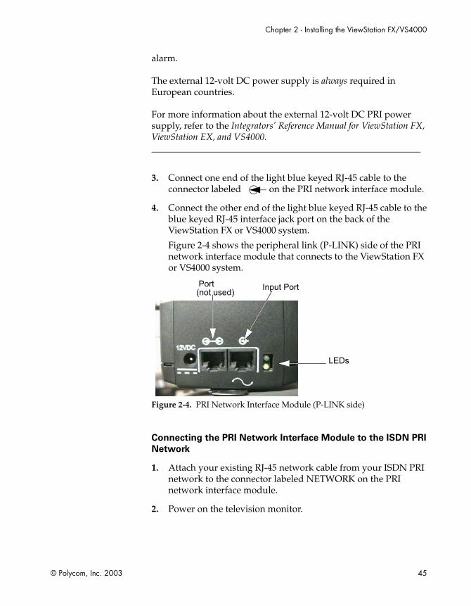
Chapter 2 - Installing the ViewStation FX/VS4000
© Polycom, Inc. 2003 45
alarm.
The external 12-volt DC power supply is always required in European countries.
For more information about the external 12-volt DC PRI power supply, refer to the Integrators’ Reference Manual for ViewStation FX, ViewStation EX, and VS4000.
3. Connect one end of the light blue keyed RJ-45 cable to the connector labeled on the PRI network interface module.
4. Connect the other end of the light blue keyed RJ-45 cable to the blue keyed RJ-45 interface jack port on the back of the ViewStation FX or VS4000 system.
Figure 2-4 shows the peripheral link (P-LINK) side of the PRI network interface module that connects to the ViewStation FX or VS4000 system.
Figure 2-4. PRI Network Interface Module (P-LINK side)
Connecting the PRI Network Interface Module to the ISDN PRI
Network
1. Attach your existing RJ-45 network cable from your ISDN PRI network to the connector labeled NETWORK on the PRI network interface module.
2. Power on the television monitor.
Port(not used) Input Port
LEDs

ViewStation FX/VS4000 User Guide
46 www.polycom.com
3. Power on the ViewStation FX or VS4000 system. Once you power up the system, there is a 20-second delay before you see the Polycom logo.
4. Once your interface is properly connected, you are ready to configure your ViewStation FX or VS4000 system. Proceed to chapter 3.
Figure 2-5 shows the NETWORK side of the PRI network interface module that connects to the ISDN PRI network.
Figure 2-5. PRI Network Interface Module (NETWORK side)
Special Information
Crossover Cable. An RJ-45 crossover cable might be required when connecting the PRI network interface module to a PBX or another third-party network access device.
External PRI Power Source. Please carefully read the Notes on page 44.
External CSU. If you are using an external CSU (North America T1 only), connect an RJ-45 cable from the CPE equipment side of the CSU to the PRI network interface module.
PRI Cable Adapter Kit. You can also purchase an additional cable adapter kit (available through your reseller) to extend the distance between your ViewStation FX or VS4000 system and the PRI network interface module.
LED Information. Refer to the PRI Technical Information section of the Integrators’ Reference Manual for ViewStation FX, ViewStation EX, and VS4000.
NETWORKConnector
LEDs

Chapter 2 - Installing the ViewStation FX/VS4000
© Polycom, Inc. 2003 47
Using a PRI E1 Module with an Adtran Atlas 800 Plus E1 Module—The Adtran Atlas 800 Plus E1 module requires firmware G03b or later. When using the G03b firmware, the user needs to wait two to three minutes after the ViewStation FX or VS4000 system has been powered on and the PRI status icon has turned green before making or receiving calls with the Adtran Atlas 800 Plus. This is due to channel restarts on the Adtran Atlas 800 Plus E1 module. If an outgoing call is attempted before this time, a "Network Congestion" message appears on the ViewStation FX or VS4000 system. An incoming call will receive a "Far Site Busy" message.
Setting up the Quad BRI Network Interface
This section explains how to install and connect the Quad BRI network interface module so that you can make calls over ISDN with the ViewStation FX or VS4000 system.
To connect the Quad BRI network interface module to the
system:
1. Make sure your system is turned off.
2. Find the cable with the light blue RJ-45 keyed connector on one end and the green RJ-45 (non-keyed) connector on the other end.
3. Insert the light blue RJ-45 keyed connector into the light blue RJ-45 keyed port on the back of the system.
4. Insert the green (non-keyed) RJ-45 connector into the green RJ-45 port labeled xon the network interface module.

ViewStation FX/VS4000 User Guide
48 www.polycom.com
Figure 2-6 shows the peripheral link (P-LINK) side of the Quad BRI network interface module that connects to the ViewStation FX or VS4000 system.
Figure 2-6. Quad BRI Network Interface Module (P-LINK side)
To connect the Quad BRI network interface module to the BRI
network:
1. Attach your RJ-45 network cable(s) from port 1 on your ISDN BRI network to the connector labeled ISDN S/T on the Quad BRI network interface module.
2. Power on the television monitor.
3. Power on the system. Once you power up the system, there is a 20-second delay before you see the Polycom logo.
4. Once your interface is properly connected, you are ready to configure your system. Proceed to chapter 3, Initial System Setup.

Chapter 2 - Installing the ViewStation FX/VS4000
© Polycom, Inc. 2003 49
Figure 2-7 shows the network side of the Quad BRI network interface module that connects to the ISDN BRI network.
Figure 2-7. Quad BRI Network Interface Module (Network side)
Special Information
Quad BRI/IMUX. The Quad BRI is also called IMUX (for Inverse Multiplexer). With the Quad BRI, you can connect up to four ISDN lines to the video conferencing unit. The Quad BRI allows multi-line ISDN connections to be “muxed” together to create a higher bandwidth connection to the far-site device. Each ISDN line adds 128 Kbps to the possible operating line.
ISDN Lines. The system can use up to four ISDN lines. Note that the system only require a single functioning ISDN line to operate, but speeds greater than 128 Kbps require the use of additional ISDN lines.
NT-1. If you are not connected to an internal phone system, called a PBX, you will need to connect the ISDN cables from your system to the Quad BRI module, to the network termination (NT-1) device, which is connected to the ISDN wall jack.
For more information about ISDN, refer to the Integrators’ Reference Manual for ViewStation EX, ViewStation FX, and VS4000.
Automatic Quad BRI Software Update. The Quad BRI is expected to have at least the same level of software version as the ViewStation FX or VS4000 system. However, if, upon reboot, the ViewStation FX or VS4000 system detects an older software version on the Quad BRI, it will automatically update the Quad BRI to the same software version. When this happens, the download is accompanied by an

ViewStation FX/VS4000 User Guide
50 www.polycom.com
explanatory message. Do NOT turn off your system during the download process.
Note
If the Quad BRI has a later software version than the ViewStation FX or VS4000 system, there is no automatic update process.
LED Information. Refer to the BRI Technical Information section of the Integrators’ Reference Manual for ViewStation EX, ViewStation FX, and VS4000.
Optional Equipment
You can enhance your videoconferences by using optional equipment. Refer to the ViewStation FX QuickStart or the VS4000 QuickStart for color cable diagrams that show how to connect optional equipment to the system.
Second Monitor
The second monitor displays what would otherwise be displayed in the smaller picture-in-picture window of a single-monitor system.
To install a second monitor:
1. Insert the monitor cable in the monitor 2 output jack.
2. Connect the other end to the monitor 2 output jack.
Auxiliary Video Cameras
You can use an additional camera to provide continuous video of different speakers in the same room.

Chapter 2 - Installing the ViewStation FX/VS4000
© Polycom, Inc. 2003 51
Cameras Supported by Polycom
The ViewStation FX and VS4000 systems are compatible with many auxiliary S-video or composite cameras. While there are many options available on the market, Polycom has tested and fully supports the following pan/tilt/zoom auxiliary cameras: Sony EVI-D30 (NTSC), Sony EVI-D31 (PAL), Sony EVI-D100 (NTSC) and the Sony EVI-D100P (PAL). Support for the Sony EVI-D100 and Sony EVI-D100P was introduced with release 4.2.
Figure 2-8. Sony EVI-D100 and Sony EVI-D30 Cameras
PowerCam Camera
This Polycom camera is supported as a secondary PTZ camera for ViewStation FX systems and as first and second cameras for VS4000.
Figure 2-9. PowerCam Camera
ViewStation FX/VS4000 User Guide
52 www.polycom.com
Note
All supported camera models can be controlled with the remote control that is shipped with the ViewStation FX or VS4000 system.
Polycom Wide-Angle Conversion Lens
This lens adaptor attaches to the front of the Sony EVI-D30 (NTSC) or the Sony EVI-D31 (PAL) cameras to increase the field of view from 48 degrees to 62.5 degrees Note that this lens is not compatible with any other camera models. You can purchase a Polycom Wide Angle Conversion Lens from your distributor or from the Polycom Store at www.polycom.com.
Caution
Attaching a third-party vendor wide-angle lens will cause damage that is not covered by your product warranty. Third-party lenses will rub against the ViewStation FX enclosure when the camera is reset.
Connecting the Sony EVI-D30 Camera
The following explains how to connect the Sony EVI-D30 camera to the ViewStation FX and the VS4000 system. Note that the ViewStation FX and VS4000 systems require different cables.
To connect the Sony EVI-D30 camera to the ViewStation FX:
The ViewStation FX system uses a single PTZ camera control cable which splits into two cables (“Y” shape).
1. Connect the two-connector side of the PTZ control cable as follows:
a. The S-Video connector plugs into the S-video port of the camera.

Chapter 2 - Installing the ViewStation FX/VS4000
© Polycom, Inc. 2003 53
b. The 8-pin DIN connector plugs into the 8-pin VISCA IN port of the camera.
2. Connect the one-connector side of the PTZ control cable by plugging in the 7-pin connector of the (PTZ) control cable into the ViewStation FX system’s auxiliary camera port (4).
To connect the Sony EVI-D30 camera to the VS4000:
The VS4000 system uses two separate cables: one S-video cable and one camera control cable (DB-9 to 8-pin mini DIN).
1. Connect the S-video cable as follows:
a. Plug one end of S-video cable into the VS4000’s camera input 1 port.
b. Plug the other end into the camera’s S-video port.
2. Connect the camera control cable as follows:
a. Plug the DB-9 connector into the VS4000’s camera control 1 port.
b. Plug the 8-pin mini DIN connector into the auxiliary camera VISCA IN port.
VCR
You can use a video cassette recorder (VCR) to record your videoconference or to present recorded material as part of your videoconference. The VCR records video from the near site’s main television monitor and audio from both the near and far sites. When playing tapes, the VCR provides audio and video to all participants in a call.
1. To play a tape in the VCR, press the NEAR button on the remote control twice.
2. Use the ARROW buttons to highlight the VCR icon on the screen. Press the SELECT button on the remote control.
3. Use the VCR remote control to play the tape.

ViewStation FX/VS4000 User Guide
54 www.polycom.com
Document Camera
You can use a document camera to take pictures of an object or document and send them to a far site.
1. To use a document camera with your system, press the NEAR button on the remote control twice.
2. Then use the ARROW buttons to highlight the Document Camera icon on the screen. Press the SELECT button on the remote control.
Visual Concert DC
Visual Concert™ DC is part of the Visual Concert series of collaboration products designed to maximize video conferencing. This is a custom-integrated document camera that has the ability to send images at SXGA (1280 x 1024) resolution with full motion capture during a video call. It lets you save images from the glass onto a PCMCIA card, annotate images with a virtual drawing pen, view transparent material using backlighting or send a high-resolution preview with the SNAPSHOT button.
For more information about installing Visual Concert DC, consult Visual Concert DC User Guide and Visual Concert DC QuickStart.
Visual Concert FX
Visual Concert™ FX is a collaborative product with the capability of transmitting a high-resolution graphics stream with high-quality audio in any conference, including multipoint calls. It is transmitted to the other site in a conference in tandem with your live video stream. It works with your laptop, desktop, or Macintosh at resolutions up to and including 1280 x 1024.
The video and graphic images can be displayed at both the near and far ends in dual stream mode, video on one monitor and the live graphics on a second monitor (for example, the far site can see you and your presentation live at the same time).
The live images can be from virtually any source on the laptop or desktop such as PowerPoint, Excel, a Web page or proprietary

Chapter 2 - Installing the ViewStation FX/VS4000
© Polycom, Inc. 2003 55
software applications. Visual Concert FX is designed to transmit graphics at SXGA resolution (1280 x 1024), but will auto-sync to match the resolution of the laptop and scale to match the best resolution at the far end. A VGA-out port on the unit allows the flexibility of connecting a high-resolution projection system or monitor for in-room displays.
Dual Stream Compatibility
Visual Concert FX dual stream is compatible with the ViewStation and the ViewStation SP systems running at least 7.0 software. A ViewStation running Visual Concert PC (or LAN version) can send dual streams to the ViewStation FX or the VS4000 system.
Visual Concert FX dual stream is compatible with the Polycom Accord MCU version 3.01 in ISDN multipoint calls. All sites are able to see the presenter and the PC at the same time.
Limitations
If the far site cannot support dual streams, the system reverts to sending the live computer screen as the main video stream.
Note
For more information about installing Visual Concert FX, consult the Visual Concert FX User Guide and Visual Concert FX QuickStart.
ShowStation IP
The ShowStation® IP allows you to project any type of document or Microsoft Office file in big-screen format and share it with any location instantly.
The ShowStation IP works best when you have two ViewStation FX or VS4000 systems, two ShowStations with LAN cards, and an RJ-45 cable. For information about installing ShowStation IP refer to the ShowStation User Guide.

ViewStation FX/VS4000 User Guide
56 www.polycom.com
To connect and use the ShowStation IP:
1. Use the provided blue RJ-45 cable to connect the ShowStation LAN card to the blue LAN port on the back of the system. You can also connect the ShowStation and the system to the same LAN.
2. Find the LAN name of the ShowStation. Click the Toolbar icon on the main menu of the ShowStation. The Site Name is under the Preferences tab.
3. Power on your system.
4. Select System Info>Admin Setup>Data Conference and enter the name of the ShowStation on the Data Conference screen.
5. Place a video call between the two ViewStation FX systems or the VS4000 systems. When the systems connect, the ShowStations synchronize with one another automatically.
Once the systems have connected, a whiteboard appears on the ShowStations’ LCD displays. It takes approximately 30 seconds for the whiteboard to appear once the video call is placed. You are now ready to use your ShowStation.

Chapter 2 - Installing the ViewStation FX/VS4000
© Polycom, Inc. 2003 57
Upgrading Software
The Softupdate application will update all versions of ViewStation software. To update the software, your system must be on local area network (LAN) or directly connected to a PC via Ethernet.
Before you begin, print the Read Me First file that is provided with the system software. It contains updated information that may not be included in this guide.
Caution
Do not power off your system during the software update process. If you turn off your system during the download process, your system reverts to its original software version.
Upgrading Software over IP
You can upgrade the software on your system with the Softupdate application available from the Software Download Center on the Polycom Web site at www.polycom.com.
If you do not have Internet access, your reseller can supply you with the application on CD-ROM.
To upgrade your system software over IP:
1. Double-click the software zip file and extract the files to a directory on your PC.
2. Double-click the Softupdate.exe file to open the Softupdate application.

ViewStation FX/VS4000 User Guide
58 www.polycom.com
Figure 2-10. Softupdate Screen
3. Click the Softupdate button, as shown in Figure 2-10.
4. Enter the IP address of the system and the administrator password, if required, then click OK.
5. In the System Info screen, specify whether to delete the address book and system files during the update.
6. Determine whether you want to make your system a DHCP server. Selecting the Allow System to be a DHCP Server option will make the Server button visible on the LAN & Intranet screen in the user interface (System Info>Admin Setup>LAN/H.323>LAN/Intranet>LAN&Intranet).
Warning
Do not select the Server option if your system is on a LAN with other computers. If you do, the system provides IP addresses to the other computers on the LAN even though the LAN already has a

Chapter 2 - Installing the ViewStation FX/VS4000
© Polycom, Inc. 2003 59
DHCP server. Your system administrators may have to repair any network problems this causes.
Figure 2-11. Softupdate System Info Screen
7. Click Continue to start the upgrade process.
8. When the upgrade has finished, click OK to close the dialog box.
Upgrading Software over ISDN (H.320)
The software on your ViewStation FX or VS4000 system can be upgraded through an ISDN (H.320) video call from any other ViewStation FX or VS4000 system.
You can perform a software update to the far site over your V.35/RS-449/RS-530, PRI, or BRI line during a call. Updating works best at speeds of 512 Kbps and below.
To upgrade your system over ISDN:
1. Place a video call to the system you want to upgrade.

ViewStation FX/VS4000 User Guide
60 www.polycom.com
2. Select System Info > Admin Setup > Security and write down the passwords that appear on the Security screen of the site you want to upgrade.
3. On the site sending the software, select System Info>Admin Setup > Software/Hardware > Update to access the Far Site Software Update screen.
4. Highlight the Start icon and press the SELECT button on the remote control.
5. Enter the passwords, highlight the Start icon, and press the SELECT button on the remote control to begin the upgrade process.
Once the software upgrade process is complete, your system automatically restarts.
Updating System Software From a PC on a LAN
To update your system software from a PC on the LAN:
1. Access the Sofupdate.exe file, as follows:
• From the Update CD: Insert the Update CD into your drive.
• From the Polycom Web site: 1. Go to the software download center at www.polycom.com. 2. Locate your product name and provide the required information. 3. Run the Softupdate application to download the latest software and update your system. Note that you need to decompress the file before you can run the Softupdate application.
2. Double-click the Softupdate.exe icon to open the application.
3. When the application opens, click the Softupdate button.
4. Enter the IP address of your videoconferencing system in the dialog box that appears. If the system has an administrator password, enter it here and click OK. If it does not have a password, leave it blank and click OK.
5. Softupdate will locate your system and provide basic information. To retain your existing address book and files,
Chapter 2 - Installing the ViewStation FX/VS4000
© Polycom, Inc. 2003 61
select the appropriate options on the Softupdate screen. Then click the Continue button.
6. As the software is being upgraded, you will be informed of its progress. When it is finished, click the OK button. Your system will automatically reboot.
Updating System Software Directly From a PC
Updating your System Software to a Higher Version
To update your system software to a higher version than the one currently on the system, follow these steps:
1. Connect one end of the blue-tipped RJ-45 cable to the blue LAN connector on the back of your system. Connect the other end of the blue-tipped RJ-45 cable to the Ethernet PC card of your computer. Then turn on your system.
2. To connect to your desktop or laptop computer, you need to set your system as a DHCP server. To do so, follow these instructions:
a. Select System Info > Admin Setup > LAN/H.323 > LAN/Intranet > LAN & Intranet.
Note
The Server button is visible on the LAN & Intranet screen only if the option Allow System to be a DHCP Server has been previously enabled in the System Info screen of the Softupdate application. For more information about enabling the option Allow System to be a DHCP Server, refer to Upgrading Software over IP.
b. In the DHCP field, select Server. The following message will appear: “The system will now issue IP addresses to other PCs on the LAN. Continue?”

ViewStation FX/VS4000 User Guide
62 www.polycom.com
Caution
Do not use this setting if your system is on a LAN with other computers. If you do, your system will provide IP addresses to the other computers even though the LAN already has a DHCP server. Your IT personnel and system administrators will have to repair any network problems this causes.
c. Select Yes if you are absolutely certain you want to set your system as a DHCP server.
d. Press Menu. The following message will appear: “Power must be reset to save changes. Continue?” Select Yes.
e. Your system will automatically restart. It will now act as a DHCP server and will provide IP addresses to one or more PCs.
3. Go to the System Information screen. You should see the IP address 1.1.1.2, which is the IP address of your system.
4. Once you get an IP address, go to your PC and follow these instructions:
For Windows 95 and 98:
a. Right-click the Network Neighborhood icon, and then right-click Properties.
b. When the Network box appears, select the Configuration tab, then double-click TCP/IP.
c. Select the IP Address tab. Make sure the Obtain an IP Address Automatically button is selected. Then click OK.
For Windows NT 4.0:
a. Right-click the Network Neighborhood icon, and then right-click Properties.
b. When the Network screen appears, select the Protocols tab, then double-click TCP/IP Protocol.
c. Select the IP Address tab. Make sure the Obtain an IP Address Automatically button is selected. Then click OK.

Chapter 2 - Installing the ViewStation FX/VS4000
© Polycom, Inc. 2003 63
For Windows 2000:
a. Right-click the My Network Places icon, and then right-click Properties.
b. In the Network and Dial-up Connections window, right-click Local Area Connection, and select Properties.
c. In the Local Area Connection Properties window, double-click Internet Protocol (TCP/IP).
d. In the Internet Protocol (TCP/IP) Properties window, make sure the Obtain an IP Address Automatically button is selected. Then click OK.
5. Restart your PC and insert the update CD into your drive. Or access the Softupdate.exe file from the Polycom Web site: 1. Go to the software download center at www.polycom.com. 2. Locate your product name and provide the required information. 3. Run the Softupdate application to download the latest software and update your system. Note that you need to decompress the file before you can run the Softupdate application.
6. Double-click the Softupdate.exe icon to open the application.
7. When the application opens, click the Softupdate button.
8. Enter the IP address of your system in the dialog box that appears. If you have an administrative password, enter it here and click OK. If you don’t have a password, leave it blank and click OK.
9. Softupdate will locate your system and provide basic configuration information. To delete your existing address book and files, check the appropriate boxes.
10. Check the box Allow System to be a DHCP Server. Then click the Continue button.
11. As the software is being upgraded, you will be informed of its progress. When it is finished, click the OK button. The system will automatically reboot. Your system software has been loaded.

ViewStation FX/VS4000 User Guide
64 www.polycom.com
Updating a System Already Loaded With the Current System Software
To update your system software from the most-current version to the same current version or higher, follow these steps:
1. Connect one end of the blue-tipped RJ-45 cable to the blue LAN connector on the back of your system. Connect the other end of the blue-tipped RJ-45 cable to the Ethernet PC card of your computer. Then turn on the system.
2. To connect to your desktop or laptop computer, you need to set your system as follows:
a. Select System Info > Admin Setup > LAN/H.323 > LAN/Intranet > LAN & Intranet.
b. Press the Up arrow on the remote control to go to the DHCP field and set it to Off.
c. In the IP Address field, enter the IP address 1.1.1.2.
d. Press Menu. The following message will appear: “Power must be reset to save changes. Continue?” Select Yes.
e. Your system will automatically restart.
3. Go to the System Information screen. You should see the IP address 1.1.1.2, which is the IP address of your system.
4. Go to your PC and follow these instructions:
For Windows 95/98:
a. Right-click the Network Neighborhood icon, and then right-click Properties.
b. When the Network box appears, select the Configuration tab, then TCP/IP, and then select the IP Address tab. Make sure the Specify an IP address button is selected.
c. Enter the following information:
– IP address = 1.1.1.3
– Subnet mask = 255.255.255.0
d. Then click OK.
Chapter 2 - Installing the ViewStation FX/VS4000
© Polycom, Inc. 2003 65
For Windows NT 4.0:
a. Right-click the Network Neighborhood icon, and then right-click Properties.
b. When the Network screen appears, select the Protocols tab, then double-click TCP/IP Protocol.
c. Select the IP Address tab. Make sure the Specify and IP Address button is selected.
d. Enter the following information:
– IP address = 1.1.1.3
– Subnet mask = 255.255.255.0
e. Then click OK.
For Windows 2000:
a. Right-click the My Network Places icon, and then right-click Properties.
b. In the Network and Dial-up Connections window, right-click Local Area Connection, and select Properties.
c. In the Local Area Connection Properties window, double-click Internet Protocol (TCP/IP).
d. In the Internet Protocol (TCP/IP) Properties window, make sure the Use the following IP address button is selected.
e. Enter the following information:
– IP address = 1.1.1.3
– Subnet mask = 255.255.255.0
f. Then click OK.
5. Restart your PC and insert the update CD into your drive. Access the Sofupdate.exe file, as follows:
• From the Update CD: Insert the update CD into your drive.
• From the Polycom Web site: 1. Go to the software download center at www.polycom.com. 2. Locate your product name and provide the required information. 3. Run the Softupdate application to download the latest software and

ViewStation FX/VS4000 User Guide
66 www.polycom.com
update your system. Note that you need to decompress the file before you can run the Softupdate application.
6. Double-click the Softupdate.exe icon to open the application.
7. When the application opens, click the Softupdate button.
8. Enter the IP address of your system in the dialog box that appears. If you have an administrative password, enter it here and click OK. If you don’t have a password, leave it blank and click OK.
9. Softupdate will locate your system and provide basic configuration information. To delete your existing address book and files, check the appropriate boxes.
10. Click the Continue button.
11. As the software is being upgraded, you will be informed of its progress. When it is finished, click the OK button. The system will automatically reboot. Your system software has been loaded.
Updating System Software Remotely
Your reseller can update your system software remotely by calling your system and downloading the new version to your system. The process takes approximately 10 to 15 minutes in a 2 x 64 kbps call. Follow these steps to remotely upgrade your system:
1. Contact your reseller to have the software update transmitted to your system.
2. Give the reseller your Software Update Password and the Admin Password (if entered) for your system. These passwords can be found on the System Info > Admin Setup > Security screen. They are implemented to prevent unauthorized access to your system.
3. The reseller will place a call to your system and download the software to your system. You will see a Remote Software Update screen on your system. This screen will keep you informed of the progress of your update. Do not turn your system off during this process.
Chapter 2 - Installing the ViewStation FX/VS4000
© Polycom, Inc. 2003 67
Note
The software update application will terminate if there are too many errors on the communication line. The system you are updating will revert back to the previous software version. If your software does not update, try using a lower data rate.
4. Once the software upgrade process completes, your system will automatically restart and the main calling screen will appear.

ViewStation FX/VS4000 User Guide
68 www.polycom.com

© Polycom, Inc. 2003 69
3Initial System Setup
This chapter describes the initial system configuration screens that you see when you power on your ViewStation FX or VS4000 for the first time.
Topics in This Chapter
The following topics are included in this chapter.
Topic Description Page
First System Screens
This section describes the first system screens that are displayed during the initial out-of-box configuration.
71
Initial Setup for IP (H.323) Calls
This section describes the initial IP-specific screens needed to configure basic network settings.
76
Initial Setup for ISDN (H.320) Calls
This sections describes the initial screens used to configure your ISDN connection (V.35/RS-449/RS-530, PRI, or BRI).
80
Final Out-of-Box System Setup Screens
The screens that complete the initial configuration sequence are covered in this section.
93
Setting up the Firewall
This section indicates where to find the appropriate firewall configuration information, if you need to set up a firewall.
96
Verifying Initial Setup
This section provides information about placing a test call and checking network connectivity.
97

ViewStation FX/VS4000 User Guide
70 www.polycom.com
Once you have powered on the ViewStation FX or the VS4000 system, a series of setup screens appear on your television monitor, leading you through the initial configuration process, which is described in the following sections.
Note
All procedures detailed in these sections must be followed in order to minimize system failures.
For the latest information about the software on your system, refer to your system’s Read Me First and Release Notes.

Chapter 3 - Initial System Setup
© Polycom, Inc. 2003 71
First System Screens
The first system screens include the following:
❑ Welcome/Language. See Selecting the Language on page 71.
❑ How to Select Menu Items. See Selecting Menu Items with the Remote Control on page 72.
❑ System Name. See Setting up System Name and Country on page 73.
❑ Country. See Setting up System Name and Country on page 73.
❑ Call Preference. See Setting your Call Preferences on page 74.
Selecting the Language
The first setup screen to appear on your television monitor is the Welcome screen.
Figure 3-1. Welcome (Language) Screen
To select the language you would like to see on the
ViewStation FX or VS4000 system:
1. Press the arrow buttons on the remote control to highlight a language.

ViewStation FX/VS4000 User Guide
72 www.polycom.com
2. Then press the SELECT button on the remote control to go to the next screen.
Note
To make selections with the remote control, aim the remote control at the remote control IR detector or at the Clarity by Polycom logo on the front of the system.
Selecting Menu Items with the Remote Control
The following screen explains how to select ViewStation FX or VS4000 items on your television monitor. Press the SELECT button on the remote control to proceed to the next screen.
Figure 3-2. How to Select Menu Items Screen
Tip
To return to a previous screen, press the MENU button on the remote control or use the arrow buttons on the remote control to highlight the Menu icon and press the SELECT button on the remote control.
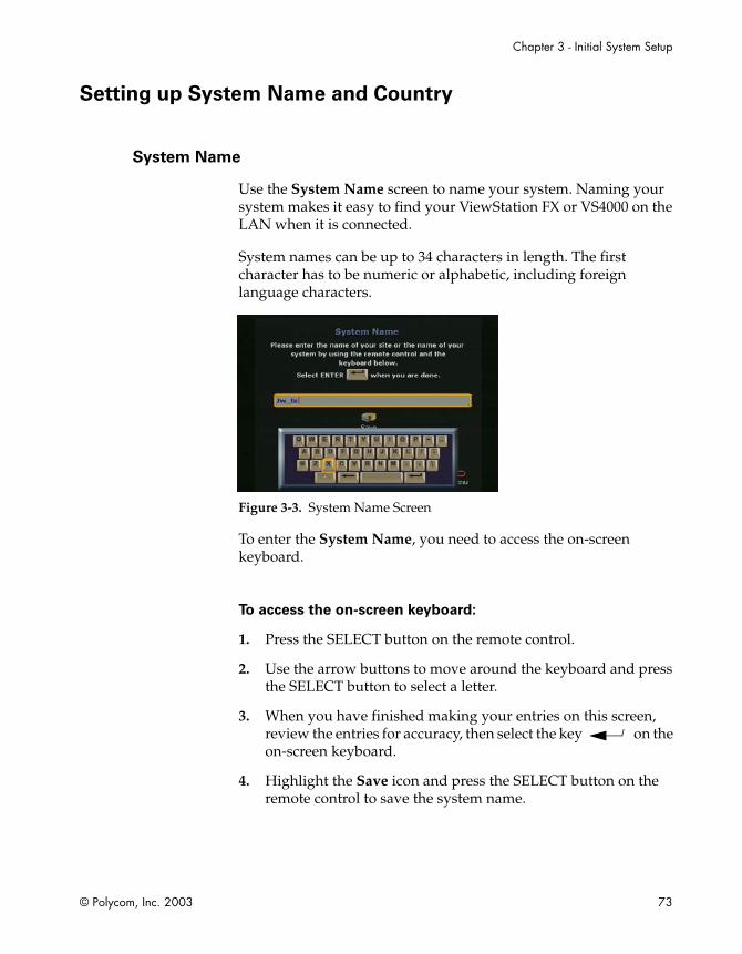
Chapter 3 - Initial System Setup
© Polycom, Inc. 2003 73
Setting up System Name and Country
System Name
Use the System Name screen to name your system. Naming your system makes it easy to find your ViewStation FX or VS4000 on the LAN when it is connected.
System names can be up to 34 characters in length. The first character has to be numeric or alphabetic, including foreign language characters.
Figure 3-3. System Name Screen
To enter the System Name, you need to access the on-screen keyboard.
To access the on-screen keyboard:
1. Press the SELECT button on the remote control.
2. Use the arrow buttons to move around the keyboard and press the SELECT button to select a letter.
3. When you have finished making your entries on this screen, review the entries for accuracy, then select the key on the on-screen keyboard.
4. Highlight the Save icon and press the SELECT button on the remote control to save the system name.
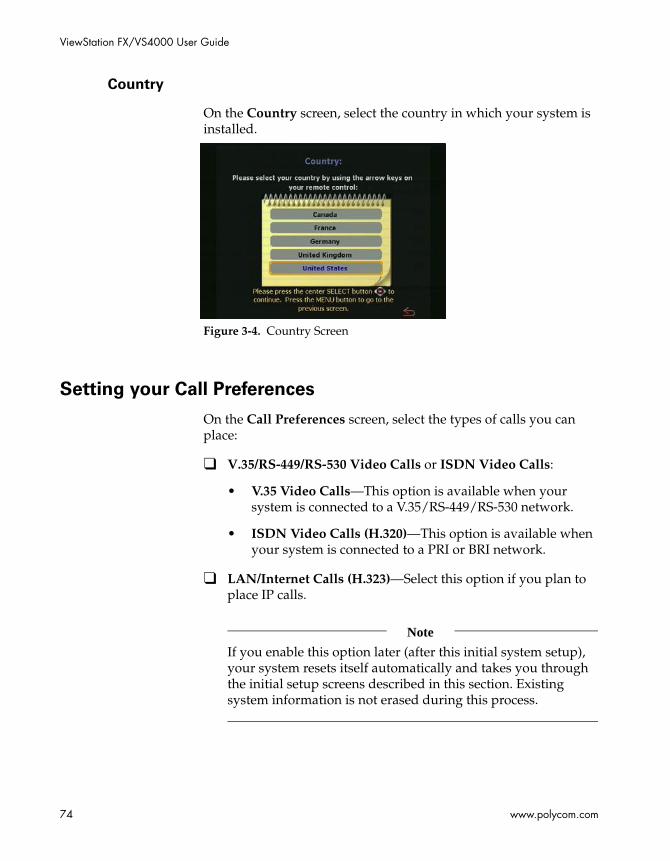
ViewStation FX/VS4000 User Guide
74 www.polycom.com
Country
On the Country screen, select the country in which your system is installed.
Figure 3-4. Country Screen
Setting your Call Preferences
On the Call Preferences screen, select the types of calls you can place:
❑ V.35/RS-449/RS-530 Video Calls or ISDN Video Calls:
• V.35 Video Calls—This option is available when your system is connected to a V.35/RS-449/RS-530 network.
• ISDN Video Calls (H.320)—This option is available when your system is connected to a PRI or BRI network.
❑ LAN/Internet Calls (H.323)—Select this option if you plan to place IP calls.
Note
If you enable this option later (after this initial system setup), your system resets itself automatically and takes you through the initial setup screens described in this section. Existing system information is not erased during this process.
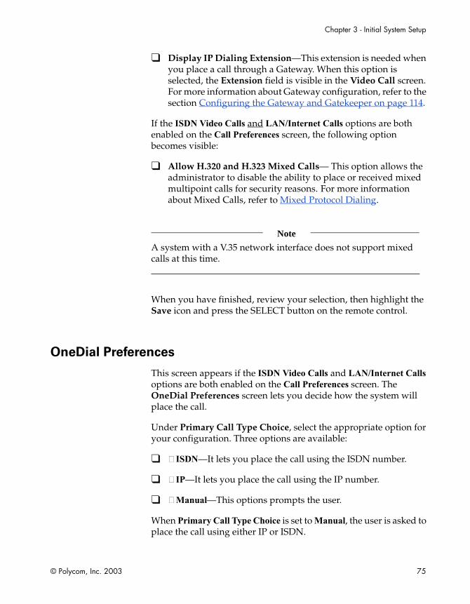
Chapter 3 - Initial System Setup
© Polycom, Inc. 2003 75
❑ Display IP Dialing Extension—This extension is needed when you place a call through a Gateway. When this option is selected, the Extension field is visible in the Video Call screen. For more information about Gateway configuration, refer to the section Configuring the Gateway and Gatekeeper on page 114.
If the ISDN Video Calls and LAN/Internet Calls options are both enabled on the Call Preferences screen, the following option becomes visible:
❑ Allow H.320 and H.323 Mixed Calls— This option allows the administrator to disable the ability to place or received mixed multipoint calls for security reasons. For more information about Mixed Calls, refer to Mixed Protocol Dialing.
Note
A system with a V.35 network interface does not support mixed calls at this time.
When you have finished, review your selection, then highlight the Save icon and press the SELECT button on the remote control.
OneDial Preferences
This screen appears if the ISDN Video Calls and LAN/Internet Calls options are both enabled on the Call Preferences screen. The OneDial Preferences screen lets you decide how the system will place the call.
Under Primary Call Type Choice, select the appropriate option for your configuration. Three options are available:
❑ ISDN—It lets you place the call using the ISDN number.
❑ IP—It lets you place the call using the IP number.
❑ Manual—This options prompts the user.
When Primary Call Type Choice is set to Manual, the user is asked to place the call using either IP or ISDN.
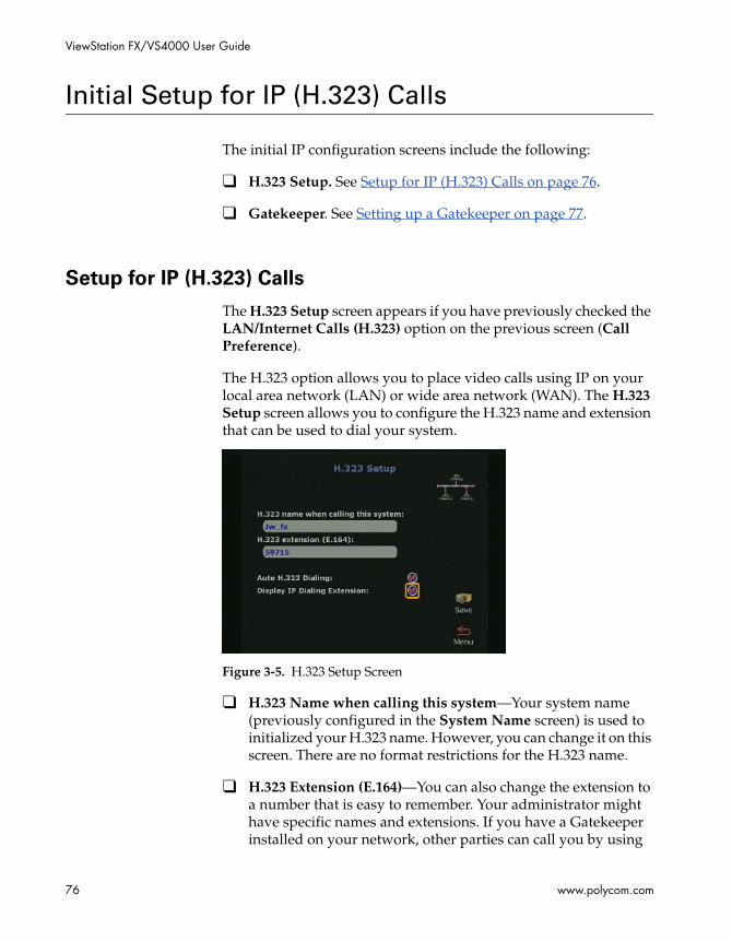
ViewStation FX/VS4000 User Guide
76 www.polycom.com
Initial Setup for IP (H.323) Calls
The initial IP configuration screens include the following:
❑ H.323 Setup. See Setup for IP (H.323) Calls on page 76.
❑ Gatekeeper. See Setting up a Gatekeeper on page 77.
Setup for IP (H.323) Calls
The H.323 Setup screen appears if you have previously checked the LAN/Internet Calls (H.323) option on the previous screen (Call Preference).
The H.323 option allows you to place video calls using IP on your local area network (LAN) or wide area network (WAN). The H.323 Setup screen allows you to configure the H.323 name and extension that can be used to dial your system.
Figure 3-5. H.323 Setup Screen
❑ H.323 Name when calling this system—Your system name (previously configured in the System Name screen) is used to initialized your H.323 name. However, you can change it on this screen. There are no format restrictions for the H.323 name.
❑ H.323 Extension (E.164)—You can also change the extension to a number that is easy to remember. Your administrator might have specific names and extensions. If you have a Gatekeeper installed on your network, other parties can call you by using

Chapter 3 - Initial System Setup
© Polycom, Inc. 2003 77
the H.323 name or extension. The H.323 name and extension are registered with your Gatekeeper. The Gatekeeper directs the call to your system IP address.
❑ Auto H.323 Dialing—This option is enabled by default to let the system auto-detect the type of call you are placing (IP or ISDN) based on the video number format. If this option is enabled, the ISDN and H.323 fields are not visible on the Video Phone screen.
❑ Display IP Dialing Extension—This option was previously configured in the Call Preference screen. For more information, refer to Setting your Call Preferences, on page 74.
Note
For additional information about H.323, see Configuration for IP (H.323) Calls on page 111.
When you have finished, review your entries for accuracy, then highlight the Save icon and press the SELECT button on the remote control.
Setting up a Gatekeeper
Use the Gatekeeper screen to configure an IP (H.323) Gatekeeper. For more detailed information about the Gatekeeper, refer to Configuring the Gateway and Gatekeeper on page 114.
Note
A Gatekeeper is not required to make an IP-to-IP LAN call. In these situations, select the Off option.
❑ H.323 Name—If you are registered with the Gatekeeper, this is the name that can be used to call your system.
❑ H.323 Extension (E.164)—H.323 extensions are needed for inbound calls going through a Gateway. This extension number

ViewStation FX/VS4000 User Guide
78 www.polycom.com
is associated with a specific LAN device. Incoming callers are prompted to enter the H.323 extension to access a specific LAN device behind the Gateway. This number may be assigned by the telephone company or by your network administrator.
❑ Use Gatekeeper. This option can be set to Off, Specify, or Auto.
• Off—If you do not want to access a Gatekeeper, select this option.
• Specify—To specify a Gatekeeper, select this option and enter the Gatekeeper’s IP address in the Gatekeeper IP Address field. This information is available from your network administrator.
• Auto—To have your system automatically find an available Gatekeeper, select the Auto option.
❑ Gatekeeper IP Address—This address is provided by your network administrator.
❑ Preferred alias—This is a valid number that outside systems can use to reach your system. Your preferred alias is generally the same number as the H.323 extension.
❑ Outbound Call Route—The Outbound Call Route via ISDN or Gateway only affects how a system dials an ISDN (H.320) call. All IP (H.323) calls are not affected by this option. Currently, a system can dial an ISDN call through ISDN or Gateway as long as it has native ISDN capability and the system is registered with a Gatekeeper. Select the appropriate option depending on your network configuration:
• Gateway: Select this option if your outbound call needs to be handled by a Gateway. This information can be obtained from your network administrator.
• ISDN: Select this option if your system is connected to an ISDN line. ISDN is the default. When you dial through ISDN, the ISDN call is made by using ISDN natively. All the prefix or suffix on the Gateway screen are irrelevant.
When you dial through Gateway, the ISDN call is made by using Gateway, not ISDN natively. If there is prefix or suffix on the Gateway screen for Gateway calls, it should be included when a call is made.

Chapter 3 - Initial System Setup
© Polycom, Inc. 2003 79
When you have finished, review your entry for accuracy, then highlight the Save icon and press the SELECT button on the remote control.

ViewStation FX/VS4000 User Guide
80 www.polycom.com
Initial Setup for ISDN (H.320) Calls
If you have an ISDN connection, you will need to configure the appropriate interface (V.35/RS-449/RS-530, PRI, or BRI). Refer to the appropriate ISDN network interface section:
❑ V.35/RS-449/RS-530. See Setup for the V.35/RS-449/RS-530 Network Interface on page 80.
❑ PRI. See Setup for the PRI Network Interface on page 86.
❑ BRI. See Setup for the Quad BRI Network Interface on page 89.
Setup for the V.35/RS-449/RS-530 Network Interface
If you have a V.35/RS-449/RS-530 network interface module, the following screens are designed to help you with your V.35/RS-449/RS-530 network configuration:
❑ Video Network. See Setting Video Network Options on page 81.
❑ Dialing Speeds. See Selecting Dialing Speeds on page 82.
❑ Broadcast Mode. See Setting Broadcast Mode Options on page 82.
❑ Advanced Dialing. See Setting Advanced Dialing Preferences on page 83.
❑ Video Numbers. See Entering V.35/RS-449/RS-530 Video Numbers on page 85.

Chapter 3 - Initial System Setup
© Polycom, Inc. 2003 81
Setting Video Network Options
Use the Video Network screen to set the parameters for your V.35/RS-449/RS-530 video network.
Figure 3-6. Video Network Screen
You can set the following options on this screen:
❑ RS-366 Dialing—Enable this option if you want to call from the system through the DCE connection to the far-end videoconferencing system. Disable this option if you are using your DCE to dial the call or if you have a dedicated connection to the far site.
Note
If the RS-366 Dialing option is enabled, you need to select Dialing Speeds on this screen (see the following Selecting Dialing Speeds section).
❑ V.35 Ports Used—Select 1 if you are placing only 1-channel calls. Select 1+2 if you are placing 2 x 56 Kbps or 2 x 64 Kbps channel calls.
❑ Dialing Protocol—RS-366 appears as the dialing protocol if the RS-366 Dialing option is enabled. If the RS-366 Dialing option is disabled, the Dialing Protocol does not appear.
❑ Broadcast Mode—Enable or disable H.331 Broadcast Mode if the system is connected to the network via satellite.

ViewStation FX/VS4000 User Guide
82 www.polycom.com
When you have finished, highlight the Save icon and press the SELECT button on the remote control.
Selecting Dialing Speeds
If you enabled RS-366 Dialing, select the Dialing Speeds icon in the Video Network screen.
1. Select the dialing speeds on this screen. The default speeds are 2 x 64 Kbps, 256 Kbps, 384 Kbps, 512 Kbps, and 768 Kbps.
2. To add or remove speeds, scroll through the data rates and press the SELECT button on the remote control to select your preferred dialing speeds; a red check appears when a dialing speed is selected.
Figure 3-7. Dialing Speeds Screen
Note
The selected dialing speeds apply only to RS-366 calls. Nx56 and Nx64 are for H.320 calls, while IPx56 and IPx64 are for H.323 calls. For non-dialed calls, the call speed is determined by the DCE.
Setting Broadcast Mode Options
If you enabled the Broadcast Mode option on the Video Network screen, the Broadcast Mode Setup icon appears. Selecting this icon takes you to the Broadcast Mode screen. For more information on

Chapter 3 - Initial System Setup
© Polycom, Inc. 2003 83
the Broadcast Mode screen, refer to Setting up Satellite (H.331) Broadcast Mode on page 123.
Setting Advanced Dialing Preferences
If you enabled RS-366 Dialing, the dialing prefixes and suffixes are set for calls from the system on the Advanced Dialing screen.
The Advanced Dialing screen lets you select the Calling Profile associated with dialing through a DCE.
Figure 3-8. Advanced Dialing Screen
Calling profiles for several manufacturers are included in your system.

ViewStation FX/VS4000 User Guide
84 www.polycom.com
To select and modify the calling profiles:
1. Select the Calling Profile field. The following calling profile list appears.
Figure 3-9. Advanced Dialing Screen (Calling Profile List)
2. Select the appropriate equipment/manufacturer from the drop-down list and press the SELECT button on the remote control.
3. When you have finished, review your entry. The Prefix or Suffix information (depending on the equipment name that you selected) is now visible on the Advanced Dialing screen.
4. Highlight the Save icon and press the SELECT button on the remote control.
Note
You have to enter the information only once on the Advanced Dialing screen. When you place a call, there is no need to enter the prefix again—simply select the preferred dialing speed, and your system enters the proper prefix.
Dialing Prefix and Suffix Information. Dialing prefixes are numbers and characters that are sent to your DCE equipment before sending the number dialed.
Dialing suffixes define the dialing speed of the DCE equipment. This provides the users with the ability to select the dialing speed when placing a call.

Chapter 3 - Initial System Setup
© Polycom, Inc. 2003 85
Prefixes and suffixes are a function of your DCE. Please consult the DCE user guide for additional information on setting dialing profiles.
Entering V.35/RS-449/RS-530 Video Numbers
If you enabled RS-366 Dialing, the Video Numbers screen appears.
Figure 3-10. Video Numbers Screen
To enter video numbers:
1. Enter the numbers that other sites can dial to call your system.
2. When you have finished, review your entry, then highlight the Save icon and press the SELECT button on the remote control.
For additional information about V.35/RS-449/RS-530 configuration, see Advanced V.35/RS-449/RS-530 Network Interface Configuration on page 121.
The initial configuration process specific to the V.35/RS-449/RS-530 network interface is complete. To continue with the initial configuration process, skip to Final Out-of-Box System Setup Screens on page 93.
Note
If you disabled RS-366 Dialing, you are operating in direct connect mode and the Video Numbers screen will not be displayed.
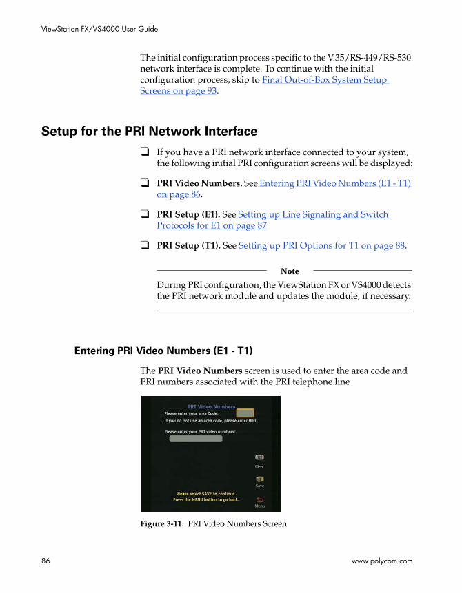
ViewStation FX/VS4000 User Guide
86 www.polycom.com
The initial configuration process specific to the V.35/RS-449/RS-530 network interface is complete. To continue with the initial configuration process, skip to Final Out-of-Box System Setup Screens on page 93.
Setup for the PRI Network Interface
❑ If you have a PRI network interface connected to your system, the following initial PRI configuration screens will be displayed:
❑ PRI Video Numbers. See Entering PRI Video Numbers (E1 - T1) on page 86.
❑ PRI Setup (E1). See Setting up Line Signaling and Switch Protocols for E1 on page 87
❑ PRI Setup (T1). See Setting up PRI Options for T1 on page 88.
Note
During PRI configuration, the ViewStation FX or VS4000 detects the PRI network module and updates the module, if necessary.
Entering PRI Video Numbers (E1 - T1)
The PRI Video Numbers screen is used to enter the area code and PRI numbers associated with the PRI telephone line
Figure 3-11. PRI Video Numbers Screen

Chapter 3 - Initial System Setup
© Polycom, Inc. 2003 87
Setting up Line Signaling and Switch Protocols for E1
This screen is specific to a PRI E1 interface.
Figure 3-12. PRI Setup Screen (for E1)
You can set the following options on the PRI Information screen:
❑ Line Signaling—The Line Signaling field provides the following choices:
• CRC4/HDB3: This is the default value. Data is encoded using HDB3 to ensure proper ones density, and CRC4 error checking is enabled on both transmit and receive.
• HDB3: CRC4 error checking is disabled.
• Switch Protocol—NET5/CTR4 is the default. It is the standard ETSI protocol derived from ITU Q.931.
If you change the country settings, a new set of PRI switch protocols is loaded.
If the current switch protocol is no longer available, you are prompted with “Do you wish to continue?” If you do, the current switch protocol is changed to the default for the selected country. This causes a reset of the PRI interface.
If more than one switch protocol is supported, you must find out from the telephone service provider which protocol to select.
The PRI network interface module originates and accepts data calls only, and does not work with incoming PRI choice calls or non-PRI lines of any kind. Special services, such as caller-id, blocking, and call forwarding, are not supported.
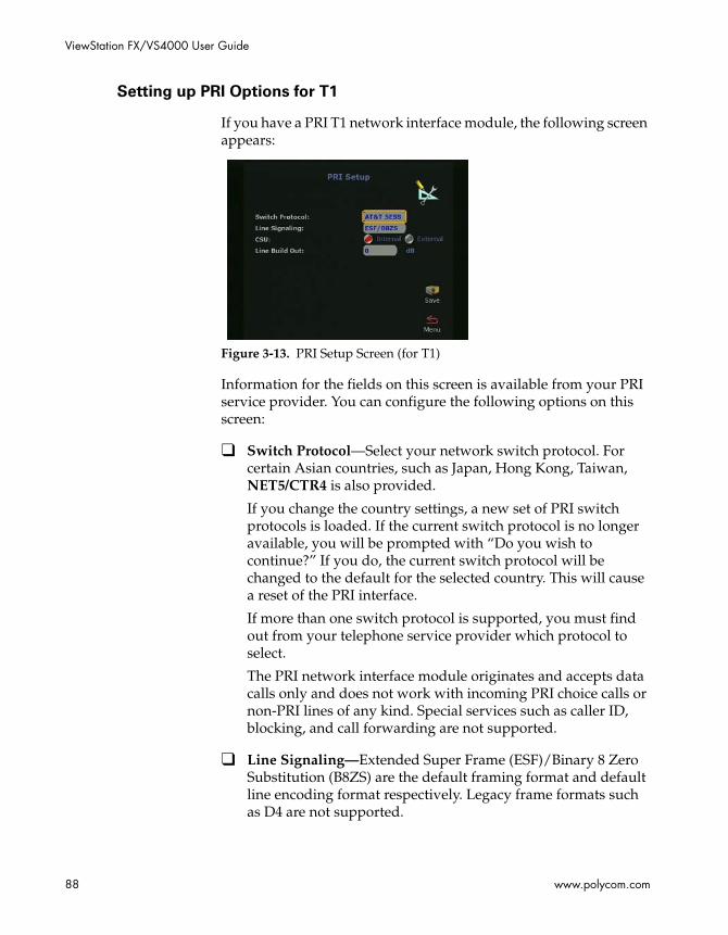
ViewStation FX/VS4000 User Guide
88 www.polycom.com
Setting up PRI Options for T1
If you have a PRI T1 network interface module, the following screen appears:
Figure 3-13. PRI Setup Screen (for T1)
Information for the fields on this screen is available from your PRI service provider. You can configure the following options on this screen:
❑ Switch Protocol—Select your network switch protocol. For certain Asian countries, such as Japan, Hong Kong, Taiwan, NET5/CTR4 is also provided.
If you change the country settings, a new set of PRI switch protocols is loaded. If the current switch protocol is no longer available, you will be prompted with “Do you wish to continue?” If you do, the current switch protocol will be changed to the default for the selected country. This will cause a reset of the PRI interface.
If more than one switch protocol is supported, you must find out from your telephone service provider which protocol to select.
The PRI network interface module originates and accepts data calls only and does not work with incoming PRI choice calls or non-PRI lines of any kind. Special services such as caller ID, blocking, and call forwarding are not supported.
❑ Line Signaling—Extended Super Frame (ESF)/Binary 8 Zero Substitution (B8ZS) are the default framing format and default line encoding format respectively. Legacy frame formats such as D4 are not supported.

Chapter 3 - Initial System Setup
© Polycom, Inc. 2003 89
❑ CSU—By default, the T1 PRI network interface module is set for internal CSU mode.
To use an external CSU, specify the following information:
1. In the CSU field, select External.
2. In the Line Buildout field, select the proper cable distance range that corresponds with the cable distance between the PRI interface and the external CSU.
North America T1 only: Connect an RJ-45 cable from the CPE equipment side of the external CSU to the PRI network interface module.
Note
For more information about the CSU, refer to the PRI Technical Information section of the Integrators’ Reference Manual for ViewStation EX, ViewStation FX, and VS4000.
❑ Line Build Out—If you are using an internal CSU, enter the output attenuation in dB. If you are using an external CSU, enter the output attenuation in feet.
Note
For more information about advanced PRI setup, see Advanced PRI Network Interface Configuration on page 129.
The initial configuration process specific to the PRI network interface is complete. To continue with the initial configuration process, skip to Initial Setup for IP (H.323) Calls on page 76.
Setup for the Quad BRI Network Interface
If you have a Quad BRI network interface connected to your system, the following initial BRI configuration screens are displayed:
❑ ISDN Video Numbers. See Entering ISDN Video Numbers on page 90.

ViewStation FX/VS4000 User Guide
90 www.polycom.com
❑ Auto Detect SPIDs. See Entering Service Profile Ids Manually on page 90.
❑ ISDN Switch Protocol. See Selecting the ISDN Switch Protocol on page 91.
Entering ISDN Video Numbers
On the ISDN Video Numbers screen, enter the area code or the STD code and ISDN number assigned to your system. Your service provider should have given you this number when you purchased your ISDN line.
When you are finished, highlight the Save icon and press the SELECT button on the remote control.
Figure 3-14. ISDN Video Numbers Screen
Entering Service Profile Ids Manually
On the Auto-Detect SPIDs screen, enter the Service Profile ID numbers for your system. If you are connected to an internal phone system (PBX), you may not need to enter SPIDs.
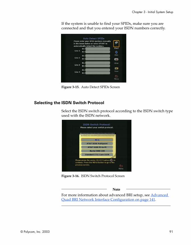
Chapter 3 - Initial System Setup
© Polycom, Inc. 2003 91
If the system is unable to find your SPIDs, make sure you are connected and that you entered your ISDN numbers correctly.
Figure 3-15. Auto Detect SPIDs Screen
Selecting the ISDN Switch Protocol
Select the ISDN switch protocol according to the ISDN switch type used with the ISDN network.
Figure 3-16. ISDN Switch Protocol Screen
Note
For more information about advanced BRI setup, see Advanced Quad BRI Network Interface Configuration on page 141.

ViewStation FX/VS4000 User Guide
92 www.polycom.com
The initial configuration process specific to the BRI network interface is complete. To continue with the initial configuration process, skip to Final Out-of-Box System Setup Screens on page 93.

Chapter 3 - Initial System Setup
© Polycom, Inc. 2003 93
Final Out-of-Box System Setup Screens
The following screens complete the initial system configuration of your system.
❑ Outside Line Calls. See Configuring for Outside Line Calls on page 93.
❑ Telephone Numbers. See Adding a Telephone Number on page 94.
❑ VS4000 Camera Setup. See Setting up the VS4000 Camera on page 94.
❑ Administrator Password. See Setting the Administrator and Meeting Passwords on page 95.
Configuring for Outside Line Calls
If your system is on a PBX, enter the number to dial for outside line access on the Outside Line Calls screen.
Figure 3-17. Outside Line Calls Screen
This number is usually 9 or 0. The system automatically dials this number before your video numbers.
Leave this screen blank if you do not need to dial a number to access an outside line. When you have finished, highlight the Save icon and press the SELECT button on the remote control.

ViewStation FX/VS4000 User Guide
94 www.polycom.com
Adding a Telephone Number
On the Telephone Numbers screen, enter the number of the analog telephone line that is connected to your system.
Figure 3-18. Telephone Numbers Screen
You can enter the number of another telephone in the same room as the ViewStation FX or VS4000 system. When you have finished, highlight the Save icon and press the SELECT button on the remote control.
Setting up the VS4000 Camera
The VS4000 Camera Setup screen is specific to the VS4000 system and lets you configure your camera equipment.
Figure 3-19. VS4000 Camera Setup Screen
Chapter 3 - Initial System Setup
© Polycom, Inc. 2003 95
You can connect four cameras to your VS4000 system. However, you can set three cameras to S-video mode, and two to pan/tilt/zoom mode.
To disable cameras, set your camera inputs as S-video or composite (VS4000 only), and enable pan/tilt/zoom capability on a camera.
The initial system configuration is complete. You are returned to the main screen.
Setting the Administrator and Meeting Passwords
This screen contains an initial administrator password, which is your system’s serial number. It also has a meeting password that is randomly generated.
The administrator password allows access to all the Admin Setup screens using the user interface or the Web interface.
You can change, remove, or keep the initial password.
To change the administrator password:
1. Highlight the password field using the remote control.
2. Backspace over the initial password (the system’s serial number) using the left arrow key on the remote control.
3. When the field is empty, start entering your new password as follows:
Enter numbers using the remote control’s keypad.
Enter letters and characters as directed below:
a. Press the SELECT button on the remote control: the on-screen keyboard appears.
b. Highlight each letter and/or character from the keyboard using the remote control arrow keys.
c. Select the letter or character by pressing the SELECT button on the remote control.

ViewStation FX/VS4000 User Guide
96 www.polycom.com
d. When you are done with your selection, select the Enter key (bottom right-most key) on the on-screen keyboard using the remote control.
4. Select the on-screen Save icon to save your changes.
Setting up the Firewall
If your system is behind a firewall, please refer to the appropriate section in the Integrators’ Reference Manual for ViewStation EX, ViewStation FX, and VS4000 to find out how to configure your system and your router.

Chapter 3 - Initial System Setup
© Polycom, Inc. 2003 97
Verifying Initial Setup
After the initial system configuration is complete, the system returns to the main menu.
The main screen is the starting point for everything you do on the ViewStation FX and VS4000. From the main screen you can access the Video Phone screen (by selecting the Video Call icon), the Address Book, all the System Info screens, and the Telephone.
The following information explains how to place a test call, and how to interpret the main screen’s network connectivity indicators.
Placing a Test Call
Once you have configured your ViewStation FX or VS4000, you can place a test call to one of the numbers that have been pre-programmed into the Address Book of your ViewStation FX or VS4000.
To place a test call:
1. Highlight the Address Book icon on the main screen and press the SELECT button on the remote control.
2. Highlight the Address Book icon again and press the SELECT button on the remote control.
3. Use the arrow buttons on the remote control to select a location and press the SELECT button on the remote control to place the call.
Checking the Network Connectivity Indicators on the Main Screen
Network connectivity indicators are also displayed on the main screen (see the following section for more information).

ViewStation FX/VS4000 User Guide
98 www.polycom.com
Note
IP Address and ISDN Number. If you press down the feet on the remote control, the IP address and/or the ISDN number of the system appear at the bottom of the main page. This is a fast and convenient way to view your IP address or ISDN number.
Network Line Check Indicators
Every time you power on your system, a numbered yellow indicator appears for every network line below the Video Call icon. If it is yellow, it indicates that the system is checking to see if the network lines are connected.
If the indicator changes to a green up arrow, system has found the network line.
If the indicator changes to a red down arrow, the system was unable to find the network line. In this case, check your network connection and verify that you entered the numbers correctly.
Figure 3-20. ViewStation FX / VS4000 Main Screens
ISDN Line Check Indicators
The system checks the configuration of the ISDN lines every time you power them on. As the system confirms each line, another line indicator appears on the ISDN check icon. Once the first ISDN line (line 1) connects, you can make a call.

Chapter 3 - Initial System Setup
© Polycom, Inc. 2003 99
Once the check is complete, and if the ISDN lines are properly configured, the indicator disappears. If it does not disappear, you should check the physical connections and the configuration of the ISDN lines.
Figure 3-21. Main Screen (showing network conditions)
Gatekeeper Status Indicators
Depending on the option selected on the Gatekeeper screen, one of the following status indicators will appear on the main screen every time you power on your system:
❑ Yellow Icon—The system is currently looking for the Gatekeeper, but has not found it yet.
❑ Red Icon—The system has detected the Gatekeeper, but it is not allowed to register with the Gatekeeper.
❑ Green Icon—The system has found the Gatekeeper and it is registered with the Gatekeeper.
❑ No Icon—No Gatekeeper was specified or set to Off in the Gateway & Gatekeeper screen (System Info > Admin Setup > LAN/H.323 > H.323 > Gateway & Gatekeeper).

ViewStation FX/VS4000 User Guide
100 www.polycom.com
© Polycom, Inc. 2003 101
4Advanced Configuration for
your Network Environment
In this chapter, you will find advanced network configuration information which can be used to enhance your videoconferencing and network environment, or to change specific options set up during the ViewStation FX or VS4000 system’s initial out-of-box configuration.
Topics in This Chapter
The following topics are included in this chapter.
Topic Description Page
Configuration of the LAN Settings
This topic explains how to configure the LAN and Intranet settings, how to set advanced LAN options, and how to configure the firewall and LAN connection.
103
Configuration for IP (H.323) Calls
This section contains advanced configuration information needed to set up your ViewStation FX or VS4000 for IP calls. It describes how to configure the Gateway and Gatekeeper information within the frame of OneDial.
111
Configuration for ISDN (H.320) Calls
The advanced configuration screens for the V.35/RS-449/RS-530, PRI, and BRI network interfaces are explained in this section.
121
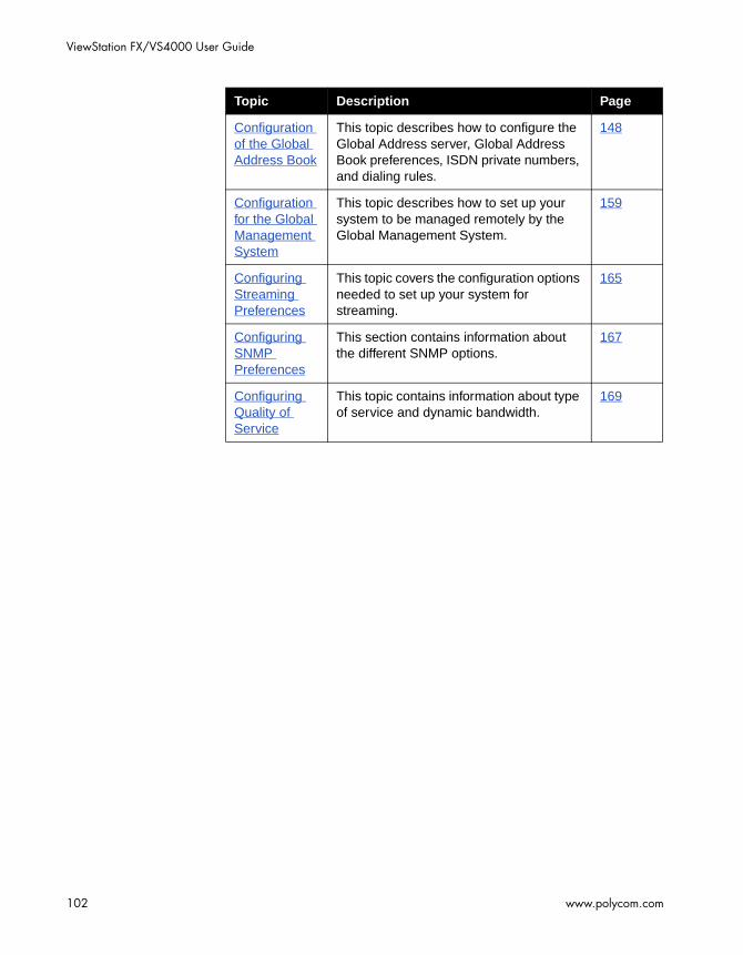
ViewStation FX/VS4000 User Guide
102 www.polycom.com
Configuration of the Global Address Book
This topic describes how to configure the Global Address server, Global Address Book preferences, ISDN private numbers, and dialing rules.
148
Configuration for the Global Management System
This topic describes how to set up your system to be managed remotely by the Global Management System.
159
Configuring Streaming Preferences
This topic covers the configuration options needed to set up your system for streaming.
165
Configuring SNMP Preferences
This section contains information about the different SNMP options.
167
Configuring Quality of Service
This topic contains information about type of service and dynamic bandwidth.
169
Topic Description Page
Chapter 4 - Advanced Configuration for your Network Environment
© Polycom, Inc. 2003 103
Configuration of the LAN Settings
This section contains advanced configuration information needed to set up the LAN options of your ViewStation FX or VS4000 system.
The following LAN and Intranet configuration screens are described in detail in this section:
❑ LAN & Intranet. See Configuring LAN and Intranet Settings.
❑ LAN Settings. See Selecting Advanced LAN Settings.
❑ Firewall & LAN Connection. See Configuring Firewall and LAN Connection Settings.
Tip
When you have finished editing the information on a screen, you can save your changes and return to the previous screen in one of two ways: press the MENU button on the remote control or highlight the Menu icon and press the SELECT button on the remote control.
Configuring LAN and Intranet Settings
The LAN & Intranet screen allows you to view LAN settings information and to enter or modify information needed to access your LAN.
To access the LAN & Intranet screen:
Select System Info > Admin Setup > LAN/H.323 > LAN/Intranet > LAN & Intranet.

ViewStation FX/VS4000 User Guide
104 www.polycom.com
Figure 4-1. LAN & Intranet Screen
On this screen, you can configure the following options:
❑ LAN Host Name—The host name is the DNS name given to your system by the network administrator. This name can be used in place of an IP address when dialing IP calls.
A LAN host name is required. It cannot be deleted or left blank. When the LAN host name is changed, the system prompts the user for a reboot.
The LAN host name follows these format rules:
• It starts and ends with an English letter (A-a to Z-z). It is not case sensitive.
• It ends with an English letter (A-a to Z-z) or a number (0 to 9).
• The characters inside the LAN host name can be English letters, numbers, and hyphen.
• It cannot be longer than 63 characters.
The initial LAN host name is initialized as follows during the out-of-box setup sequence:
• If the system name is a valid LAN host name (meaning that it follows the preceding format rules), then the LAN host name is the same as the system name.
• If the system name is not a valid LAN host name (meaning that it does not follow the preceding format rules), the invalid characters are removed from the system name to

Chapter 4 - Advanced Configuration for your Network Environment
© Polycom, Inc. 2003 105
obtain a valid LAN host name. If the resulting string is empty, the default LAN host name is Admin.
❑ WINS Resolution—WINS resolution (Windows Internet Name Service) allows a network device name (the name of your ViewStation FX or VS4000)to be resolved to an IP address in a routed environment.
When this option is selected, the system sends requests to the WINS server for WINS name resolution.
❑ DHCP—The Dynamic Host Configuration Protocol allows a server to dynamically assign IP addresses to devices on a LAN. You can set the DHCP option to Off, Client, or Server.
• Off: When Off is selected, the IP address, DNS servers, default gateway, subnet mask, and WINS server information must be entered as static addresses. These addresses are permanent until they are manually changed.
• Client: If your system is connected to a LAN, enable the Client option. When this option is selected, your company’s DHCP server automatically assigns an IP address, a DNS server address, a default gateway, a subnet mask, and a WINS server address. When Client is enabled, the options IP Address, DNS Servers, Default Gateway, Subnet Mask, and WINS Server cannot be changed.
• Server: If you are connecting the system directly to a PC that is not connected to the network, enable the Server option. When this option is selected, the system’s DHCP server can assign up to 12 IP addresses ranging from 1.1.1.3 to 1.1.1.14 to network devices on your LAN.
The Server button is visible on the LAN & Intranet screen only if the option Allow System to be a DHCP Server has been previously enabled in the System Info screen of the Softupdate application.
For more information about enabling the option Allow System to be a DHCP Server, refer to Upgrading Software on page 57.

ViewStation FX/VS4000 User Guide
106 www.polycom.com
Warning
Do not select the Server option if your system is on a LAN with other computers. If you do, the system provides IP addresses to the other computers on the LAN even though the LAN already has a DHCP server. Your system administrators may have to repair any network problems this causes.
❑ IP Address—If the DHCP Client option is selected, an IP address is automatically assigned to the system from your network server and you cannot make any change to this field. If the DHCP Off option is selected, you need to enter a static IP address for your system. The IP address can be obtained from your network administrator or your IT department.
❑ DNS Servers—DNS servers are computers which translate domain names (example: www.polycom.com) into IP addresses.
If the DHCP Client option is selected, the DNS server addresses are automatically filled in and you cannot make any change to this field. If the DHCP Off option is selected, you need to enter the DNS server addresses manually. These addresses can be obtained from your network administrator or your IT department.
❑ Default Gateway—The default Gateway is a router on the local network. Its main task it to act as an interpreter between two systems that do not use the same communications protocol, data formatting, and other network functions. Your system must go through this router to access destinations outside of its network.
If the DHCP Client option is selected, the Default Gateway address is automatically filled in and you cannot make any change to this field. If the DHCP Off option is selected, you need to enter the address manually. This information can be obtained from your network administrator or your IT department.
❑ Subnet Mask—A subnet mask is a number that identifies a subnetwork so that an IP address can be shared on a local

Chapter 4 - Advanced Configuration for your Network Environment
© Polycom, Inc. 2003 107
network. This is the subnet mask of the LAN to which your system is connected.
If the DHCP Client option is selected, the subnet mask address is automatically filled in and you cannot make any change to this field. If the DHCP Off option is selected, you need to enter the address manually. The subnet mask can be obtained from your network administrator or your IT department.
❑ WINS Server—This is a Windows NT computer that resolves computer names to IP addresses in a routed environment. Find out from your network administrator or your IT department whether you need a WINS Server IP address or not.
Selecting Advanced LAN Settings
You can select the LAN port on your system and set or change its LAN speed and duplex mode on the Advanced LAN Settings screen.
To access the Advanced LAN Settings screen:
Select System Info > Admin Setup > LAN/H.323 > LAN/Intranet > Advanced LAN Settings.
Figure 4-2. Advanced LAN Settings Screen
On the Advanced LAN Settings screen, you can select a LAN port and a LAN speed as described below:

ViewStation FX/VS4000 User Guide
108 www.polycom.com
Note
Before you select a LAN speed and duplex mode, find out from your network administrator what speed and duplex mode are supported by the switch to which your system is connected.
❑ Select LAN Port—The ViewStation supports a LAN port and a PC port:
• The LAN Port option represents the LAN port on the back of your system. This port is used to directly connect your system to your LAN network.
• The other port, the PC Port, can be used to connect a device to the LAN network through your system (which, in this case, acts as a hub), or to directly connect a device such as a PC to a system not on the LAN network.
❑ LAN Speed—This option can be set to Auto, 10 MBps, or 100 MBps (megabits per second).
• Auto: When this option is selected, the network switch to which the system is connected automatically negotiates the LAN speed and duplex mode.
• 10 MBps or 100 MBps: When one of these LAN speeds is selected, a duplex mode must be selected (see Duplex Mode below).
❑ Duplex Mode—This option can be set to Auto, Full, or Half.
• Auto: When this option is selected, the network switch to which the system is connected automatically negotiates the duplex mode.
• Full: This duplex mode allows for bi-directional, simultaneous, two-way communications.
• Half: This duplex mode allows for bi-directional data transmission, but not at the same time.

Chapter 4 - Advanced Configuration for your Network Environment
© Polycom, Inc. 2003 109
Configuring Firewall and LAN Connection Settings
The Firewall & LAN Connection screen allows the LAN manager to configure firewall options.
To access the Firewall & LAN Connection screen:
Select System Info > Admin Setup > LAN/H.323 > LAN/Intranet > Firewall/LAN Connection. The following screen appears:
Figure 4-3. Firewall & LAN Connection Screen
In this screen, you can configure the following options:
❑ Use Fixed Ports—Specify the fixed ports assigned to the system when working with a firewall. For information on port assignments in multipoint calls, refer to Multipoint Calls and Firewall Information on page 215.
❑ System is Behind a NAT—This option instructs the system to use the IP address that appears in the NAT Outside (WAN) Address field as its external IP address. When using a Virtual Private Network (VPN) for your network connection, make sure that System is Behind a NAT is not selected.
If your system is behind a NAT device that is not H.323 aware, then select this option. If your system is behind an H.323-aware NAT device, make sure the option is not selected or your system will not be able to make and receive calls.
❑ Auto Discover NAT—When this option is selected, the system can get its IP address from the NAT device.

ViewStation FX/VS4000 User Guide
110 www.polycom.com
❑ NAT Outside (WAN) Address—Specify the external IP address used by your NAT. If the system is unable to discover your external IP address automatically, you can enter it here.
Note
For more information about configuring your system to operate behind a NAT (Network Address Translation) device, refer to the Integrators’ Reference Manual for ViewStation EX, ViewStation FX, and VS4000.

Chapter 4 - Advanced Configuration for your Network Environment
© Polycom, Inc. 2003 111
Configuration for IP (H.323) Calls
This section contains advanced configuration information needed to set up your ViewStation FX or VS4000 system for IP calls.
The following IP configuration screens are described in detail in this section:
❑ H.323 Setup. See Configuration for IP (H.323) Calls.
❑ Dialing Speed. See Selecting Dialing Speeds.
❑ Gateway & Gatekeeper. See Setting the Gateway and Gatekeeper.
❑ Gateway Number. See Configuring the Gateway Number.
❑ Gateway. See Selecting your Gateway Prefix and Suffix.
To access the system’s IP (H.323) configuration screens:
Select System Info > Admin Setup > LAN/H.323.
Note
When your IP configuration is complete, you may want to place a test call. For information about placing a call, refer to Video Calls on page 176.

ViewStation FX/VS4000 User Guide
112 www.polycom.com
Configuring H.323 Name and Extension
The H.323 name and extension that can be used to dial your system are configured in the H.323 Setup screen.
To access the H.323 Setup configuration screen:
Select System Info > Admin Setup > LAN/H.323 > H.323 > Setup. The H.323 Setup screen appears.
Figure 4-4. H.323 Setup Screen (configuration)
Following is a description of the options displayed on the screen:
❑ H.323 Name when calling this system—Your system name appears as your H.323 name, but you can change it on this screen.
❑ H.323 Extension (E.164)—This is the number that is needed to access a specific LAN device for incoming calls. You can change the extension to a number that is easy to remember. Your administrator might have specific names and extensions. If you have a Gatekeeper installed on your network, other parties can call you by using the H.323 name or extension. The H.323 name and extension are registered with your Gatekeeper.
❑ Auto H.323 Dialing—When this option is enabled, the system is able to automatically detect the type of call you are placing (IP or ISDN) based on the video number format. Consequently, the ISDN (or V.35) and IP fields are not visible on the Video Phone screen. This option is enabled by default.

Chapter 4 - Advanced Configuration for your Network Environment
© Polycom, Inc. 2003 113
❑ Display IP Dialing Extension—This extension is needed when placing a call through a Gateway. When this option is selected, the Extension field is visible in the Video Phone screen.
Note
It is a good idea to consult your network administrators before changing your H.323 name and extension; they might have specific names and extensions they want you to use.
Selecting Dialing Speeds
The Dialing Speeds lets you limit the choices that appear as speed selections. Offering a minimum number of speeds is a way to lower network traffic. The speeds that are selected in this screen will be displayed as dialing speed selections in the Video Phone and in the Address Book screens.
To access the Dialing Speeds screen:
Select System Info > Admin Setup > LAN/H.323 > H.323 > Dialing Speeds. The Dialing Speeds screen appears.
Figure 4-5. Dialing Speeds Screen

ViewStation FX/VS4000 User Guide
114 www.polycom.com
To select dialing speeds:
1. Choose the appropriate dialing speeds. The default dialing speeds are 2 x 64 Kbps, 128 Kbps, 256 Kbps, 384 Kbps, 512 Kbps, and 768 Kbps.
2. To add or remove speeds, scroll through the data rates and press the SELECT button on the remote control to select your preferred dialing speeds; a red check appears when a dialing speed is selected.
The Nx56 and Nx64 columns list the dialing speeds available for ISDN calls.
The IPx56 and IPx64 columns list the dialing speeds available for IP calls.
Configuring the Gateway and Gatekeeper
Overview
Gateway and Gatekeeper settings are configured in several screens:
❑ Gateway & Gatekeeper. See Setting the Gateway and Gatekeeper.
❑ Gateway Number. See Configuring the Gateway Number.
❑ Gateway. See Selecting your Gateway Prefix and Suffix.
These screens let users enter advanced Gateway and Gatekeeper information that is part of Polycom OneDial, a Polycom-proprietary feature.
Note
The configuration screens described in this section require an excellent understanding of Gateways and Gatekeepers. Configuring these options should be best handled by knowledgeable network administrators. Additionally, configuring settings in this screen has no effect if you are not using a Gatekeeper or Gateway.

Chapter 4 - Advanced Configuration for your Network Environment
© Polycom, Inc. 2003 115
A Gatekeeper is a “network administrator” that supervises the network traffic going through it. It manages functions such as address resolution, bandwidth control, admission control, etc. If your system is not registered with a Gatekeeper, it may not be authorized to place IP calls. In particular, the Gatekeeper provides address translation between aliases and IP addresses, allowing users to maintain the same telephone numbers or alias addresses regardless of changes to their network addresses.
A Gateway is a node on two networks that connects two otherwise incompatible networks. It usually performs code and protocol conversion processes. In short, it translates between IP and ISDN protocols.
About Polycom OneDial
Polycom OneDial greatly simplifies videoconferencing dialing by taking care of a number of dialing and network processes in the background. All the user has to do is select a name in the Address Book directory or enter the simplified phone number to initiate a call. This name hides complex configuration information and processes: for example, complicated numbers, prefixes, codes, network choices (IP or ISDN) and gateway and gatekeeper operations. OneDial also takes care of bandwidth renegotiation (downspeeding), alternate routing (if IP routing does not work, OneDial will attempt to do ISDN), and Conference on Demand™.
OneDial lets users from any video endpoint create instant multipoint conferences without network administrator or IT assistance by clicking a name in the Address Book. This service is provided by a combination of Polycom’s products PathNavigator™ (a call processing server) and the MGC-110 or MGC-50 (multipoint control unit).
OneDial is part of PathNavigator, a call processing server that performs Gateway, Gatekeeper, and name resolution operations in the background.
For more in-depth descriptions and configuration information about OneDial and PathNavigator, refer to the Integrators’ Reference Manual for ViewStation EX, ViewStation FX, and VS4000.

ViewStation FX/VS4000 User Guide
116 www.polycom.com
Setting the Gateway and Gatekeeper
The Gateway & Gatekeeper screen allows you to enter advanced H.323 information, a Gatekeeper IP address if needed, and select a route for your outbound calls.
To access the Gateway & Gatekeeper screen:
Select System Info > Admin Setup > LAN/H.323 > H.323 > Gateway & Gatekeeper.
Changes made in the Gateway & Gatekeeper screen will cause the system to automatically reset itself in order to enable the new configuration and properly register with the Gatekeeper.
Figure 4-6. Gateway & Gatekeeper Screen
On this screen, you can set the following options:
❑ H.323 Name—If you are registered with the Gatekeeper, this is the name that can be used to call your system.
❑ H.323 Extension (E.164)—H.323 extensions are needed for inbound calls going through a Gateway. This extension number is associated with a specific LAN device. Incoming callers are prompted to enter the H.323 extension to access a specific LAN device behind the Gateway. This number may be assigned by the telephone company or by your network administrator.
❑ Use Gatekeeper—The options are Off, Specify, and Auto.
• Off: If you do not want to access a Gatekeeper, select the Off option.

Chapter 4 - Advanced Configuration for your Network Environment
© Polycom, Inc. 2003 117
Note
A Gatekeeper is not required to make IP-to-IP LAN calls. In these situations, select the Off option.
• Specify: To specify a Gatekeeper, select the Specify option and enter the Gatekeeper’s IP address or name (for example, gatekeeper.companyname.usa.com) in the Gatekeeper’s IP Address field. This information is available from your network administrator.
• Auto: To have system automatically find an available Gatekeeper, select the Auto option.
❑ Gatekeeper IP Address—If you have selected Specify under Use Gatekeeper, enter the Gatekeeper’s IP address or name in this field.
❑ Outbound Call Route—The Outbound Call Route via ISDN or Gateway only affects how a system dials an ISDN (H.320) call. All IP (H.323) calls are not affected by this option.
Currently, a system can dial an ISDN call through ISDN or Gateway as long as it has native ISDN capability and the system is registered with a Gatekeeper. Select the appropriate option depending on your network configuration:
• Gateway: Select this option if your outbound call needs to be handled by a Gateway. This information can be obtained from your network administrator.
• ISDN: Select this option if your system is connected to an ISDN line. ISDN is the default.
When you dial through ISDN, the ISDN call is made by using ISDN natively. All the prefix or suffix on the Gateway screen are irrelevant.
When you dial through Gateway, the ISDN call is made by using Gateway, not ISDN natively. If there is prefix or suffix on the Gateway screen for Gateway calls, it should be included when a call is made.

ViewStation FX/VS4000 User Guide
118 www.polycom.com
Configuring the Gateway Number
The Gateway Number screen allows users to enter advanced IP information that is part of Polycom OneDial. For more information about OneDial, refer to About Polycom OneDial, on page 115.
To access the Gateway Number screen:
Select System Info > Admin Setup > LAN/H.323 > H.323 > Gateway > Gateway Number. The Gateway Number screen appears.
Figure 4-7. Gateway Number Screen
On this screen, you can configure the following options:
❑ Gateway Number Type
• Direct Inward Dial (DID): DID allows a caller outside a company to call an internal extension without having to go through an operator. When using DID, the number of digits in the DID is that portion of the full DID that the Gateway will be given from the ISDN service provider as the Called Party Line Identifier. This, in turn, will be passed to the Gatekeeper for address resolution. The endpoint needs to register this portion of the DID as an E.164 alias with the Gatekeeper in order for this to work.
• Number + Extension: If enabled, this option allows the call to go through directly (it dials the Gateway number + ## + Extension as one number).

Chapter 4 - Advanced Configuration for your Network Environment
© Polycom, Inc. 2003 119
❑ Gateway Number—This is the number that is used by the outside world (WAN) to access your LAN. To access a specific device on the LAN, the Gateway Number needs an H.323 extension (described in Setting the Gateway and Gatekeeper, on page 116). Enter the Country Code, Area Code, and Number information.
❑ Number of digits in DID number—This is determined by your network administrator.
❑ Number of digits in extension—This is determined by your network administrator.
Selecting your Gateway Prefix and Suffix
The Gateway screen allows users to enter advanced Gateway information that is part of the Polycom OneDial feature. For more information about OneDial, refer to About Polycom OneDial, on page 115.
To access the Gateway screen:
Select System Info > Admin Setup > LAN/H.323 > H.323 > Gateway (page 2). The Gateway screen appears:
Figure 4-8. Gateway Screen
ViewStation FX/VS4000 User Guide
120 www.polycom.com
You can configure the prefix or suffix that is sent to the Gatekeeper. The prefix identifies which Gateway is used to dial a call at a particular data rate. The Gatekeeper then directs the call to the Gateway that is identified with a prefix.
For example, the system inserts the prefix “90” before the number when dialing a 256 Kbps Gateway call. The prefix tells the Gatekeeper which Gateway to use to dial the 256 Kbps call.
To determine the appropriate codes for the call speeds, consult your Gateway instruction manual. These codes are programmed into the Gateway and Gatekeeper.
Note
This information should be configured by a knowledgeable network administrator.
Chapter 4 - Advanced Configuration for your Network Environment
© Polycom, Inc. 2003 121
Configuration for ISDN (H.320) Calls
This section contains advanced ISDN configuration information for the V.35/RS-449/RS-530, PRI, and BRI network interfaces. The information displayed on the various ISDN configuration screens varies according to the network interface that is attached to your ViewStation FX or VS4000 system. The configuration information is divided into:
❑ Advanced V.35/RS-449/RS-530 Network Interface Configuration
❑ Advanced PRI Network Interface Configuration
❑ Advanced Quad BRI Network Interface Configuration
Once your ISDN configuration is complete, you may want to place a test call. For information about placing a call, refer to Video Calls on page 176.
Advanced V.35/RS-449/RS-530 Network Interface Configuration
This section describes information and settings for the following advanced V.35/RS-449/RS-530 configuration screensR:
❑ Advanced V.35 (Setup). See Configuring the V.35/RS-449/RS-530 Serial Interface Control Signals, on page 122.
❑ Broadcast Mode. See Setting up Satellite (H.331) Broadcast Mode, on page 123.
❑ Dialing Speeds. See Selecting Dialing Speeds, on page 125.
❑ Advanced Dialing (Calling Profile, Prefix, Suffix). See Setting the Calling Profile, on page 126.
❑ Crypto Resync Pulse. See Enabling Crypto Resync on page 128.
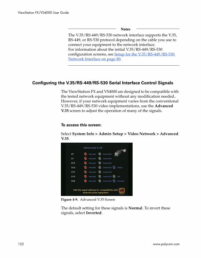
ViewStation FX/VS4000 User Guide
122 www.polycom.com
Notes
The V.35/RS-449/RS-530 network interface supports the V.35, RS-449, or RS-530 protocol depending on the cable you use to connect your equipment to the network interface.For information about the initial V.35/RS-449/RS-530 configuration screens, see Setup for the V.35/RS-449/RS-530 Network Interface on page 80.
Configuring the V.35/RS-449/RS-530 Serial Interface Control Signals
The ViewStation FX and VS4000 are designed to be compatible with the tested network equipment without any modification needed.. However, if your network equipment varies from the conventional V.35/RS-449/RS-530 video implementations, use the Advanced V.35 screen to adjust the operation of many of the signals.
To access this screen:
Select System Info > Admin Setup > Video Network > Advanced V.35.
Figure 4-9. Advanced V.35 Screen
The default setting for these signals is Normal. To invert these signals, select Inverted.
Chapter 4 - Advanced Configuration for your Network Environment
© Polycom, Inc. 2003 123
Note
For more detailed information about serial interface control signals, to the Integrators’ Reference Manual for ViewStation EX, ViewStation FX, and VS4000.
Direct Connect
The following information applies only to V.35 Direct Connect setups.
Direct Connect users can choose to have the local system answer a video call when it detects data from a remote site, or hang up when it detects lack of data from the remote site. This Direct Connect signal lead would be in addition to existing V.35 signal leads that control answer/hang up call states. A description of the use of these signals can be found in the Integrators’ Reference Manual for ViewStation EX, ViewStation FX, and VS4000.
Setting up Satellite (H.331) Broadcast Mode
The ViewStation FX and VS4000 with a V.35/RS-449/RS-530 network interface support H.331 broadcast mode for broadcast transmissions via satellite. In this mode, your system sends and receives audio and video without handshaking with the far-site system or H.331-compatible systems.
One system can send video and audio to many systems or other H.331-compatible systems, such as large satellite network.
Broadcast configuration parameters should be set to accommodate the lowest common denominator of the systems which are receiving the broadcast. For example, if one system in the conference supports H.261 only, broadcast should be set to H.261 to ensure all systems participate in the conference.

ViewStation FX/VS4000 User Guide
124 www.polycom.com
To access the Broadcast Mode screen:
1. Enable Broadcast Mode Setup in the Video Network screen (System Info > Admin Setup > Video Network > Video Network). The Broadcast Mode Setup satellite icon appears.
2. Select the Broadcast Mode Setup icon to access the Broadcast Mode configuration screen.
Figure 4-10. Video Network Screen and Broadcast Mode Screens
On the Broadcast Mode screen, you can set the following video
and audio preferences:
❑ Video Format—Select QCIF to transmit Quarter Common Interchange Format (176 x 144 resolution). Select FCIF to transmit FCIF (Full CIF 352 x 288 resolution)
❑ Video Protocol—Select H.261 to transmit video using the H.261 video standard. Select H.263 to transmit video using the H.263 enhanced video algorithm. Far-end systems that support H.263 receive H.263.
❑ Audio Mode—Select the preferred audio protocol to transmit audio: G.728, G.711u, G.711A, G.722-56, G.722-48, or Off.
❑ Frame Rate—Select the preferred video frame rate for the broadcast transmission: 30 fps, 15 fps, 10 fps, or 7.5 fps.

Chapter 4 - Advanced Configuration for your Network Environment
© Polycom, Inc. 2003 125
Selecting Dialing Speeds
This screen lets you limit the choices that appear as speed selections. Offering a minimum number of speeds is a way to lower network traffic. The speeds that are selected in this screen will be displayed as dialing speed selections in the Video Phone and in the Address Book screens.
To select dialing speeds:
1. Enable RS-366 Dialing on the Video Network screen (System Info > Admin Setup > Video Network > Video Network).
2. Select Dialing Speeds. Choose the appropriate dialing speeds on the Dialing Speeds screen.
The default dialing speeds are 2 x 64 Kbps, 128 Kbps, 256 Kbps, 384 Kbps, 512 Kbps, and 768 Kbps.
3. To add or remove speeds, scroll through the data rates and press the SELECT button on the remote control to select your preferred dialing speeds; a red check appears when a dialing speed is selected.
The selected dialing speeds apply only to RS-366 calls.
The Nx56 and Nx64 columns list the dialing speeds available for ISDN calls.
The IPx56 and IPx64 columns list the dialing speeds available for IP calls.
For non-dialed calls, the call speed is determined by the DCE.
Figure 4-11. Dialing Speeds Screen

ViewStation FX/VS4000 User Guide
126 www.polycom.com
Note
A V.35/RS-449/RS-530 system cannot receive an inbound call from a non-V.35/RS-449/RS-530 system at an n x 56 k common speed. Common speeds are speeds that are divisible by both 56 and 64. These include 8 x 56k (448 or 7 x 64), 16 x 56k (896 or 14 x 64), and 24 x 56k (1344 or 21 x 64). Because a V.35/RS-449/RS-530 system cannot determine how bandwidth is allocated–it only receives the total clock speed–it does not know how these “common speed” connections are supposed to be established. This causes problems when a non-V.35/RS-449/RS-530 system calls a V.35/RS-449/RS-530 system at one of these n x 56k common speeds (the connection is not established correctly).
Setting the Calling Profile
The Advanced Dialing screen lets you set or modify your calling profile. Calling profiles for several manufacturers are included in the ViewStation FX and VS4000 system.
If you enabled RS-366 Dialing, you need to set the dialing prefixes and suffixes associated with dialing through your particular DCE equipment and your system.
Dialing prefixes are numbers and characters that are sent to your DCE equipment before sending the number dialed.
Dialing suffixes are numbers and characters that are sent to your DCE equipment after the number is dialed.
Prefixes and suffixes are used to tell your DCE equipment at what speed to dial the call. Users have only to select the dialing speed when they place a call.
Note
Prefixes and suffixes are a function of your DCE. Please consult the DCE user guide for additional information on setting dialing profiles.

Chapter 4 - Advanced Configuration for your Network Environment
© Polycom, Inc. 2003 127
To set or modify the calling profile:
1. Make sure that RS-366 Dialing is enabled on the Video Network screen (System Info > Admin Setup > Video Network).
2. On the Video Network screen, select Advanced Dialing.The Advanced Dialing screen appears. This screen lets you select or modify the Calling Profile associated with dialing through a DCE.
Figure 4-12. Advanced Dialing Screen (Page 1)
3. Select the Calling Profile field if you select or modify your Calling Profile associated with dialing through your DCE. The following calling profile list appears.
Figure 4-13. Advanced Dialing Screen (Calling Profile List)
4. Select the appropriate equipment/manufacturer from the drop-down list and press the SELECT button on the remote control.

ViewStation FX/VS4000 User Guide
128 www.polycom.com
5. When you have finished, review your entry. The Prefix or Suffix information (depending on the equipment name that you selected) is now visible on the Advanced Dialing screen.
Note
You have to enter this information only once on the Advanced Dialing screen. When you place a call, there is no need to enter the prefix again; simply select the preferred dialing speed and the system enters the proper prefix.
Enabling Crypto Resync
If a cryptographic encoder/decoder is connected between the ViewStation FX or the VS4000 system and the network, it may require a resynchronization signal from the ViewStation FX or VS4000. This is a signal indicating that the ViewStation FX or the VS4000 has lost video synchronization due to a network problem and requires that the cryptographic encoder/decoder resync with the equipment at the other end of the connection
To access the Crypto Resync Pulse screen:
1. Select System Info > Admin Setup > Security.
2. In the Security screen, select the Crypto Resync option.The Crypto Resync Pulse screen appears.
Figure 4-14. Crypto Resync Pulse Screen

Chapter 4 - Advanced Configuration for your Network Environment
© Polycom, Inc. 2003 129
You can configure the following options on this screen:
❑ Crypto Resync—This option is Off by default. To enable Crypto Resync, select On.
❑ Time Between Pulses (sec)—This option lets you set the time between pulses (in seconds).
❑ Pulse Width (millisec)—This option lets you set the pulse width (in milliseconds).
If the system is in a call, and it loses H.320 synchronization, it continuously sends the resynchronization pulses at the specified rate with the specified pulse width until H.320 regains synchronization.
The resync pulse is output on the RTS signal. If this feature is enabled, the RTS signal no longer functions as the Ready-To-Send signal.
Most installations that use encryption equipment require a custom cable. The cable should be designed to route the RTS signal from the system to the appropriate resync input on the encryption equipment. The encryption equipment can get its RTS input from the system’s DTR output or by wiring this input to an always-high tie-off. In this non-dialed mode, the DTR output and RTS output act exactly the same.
Note
Refer to Integrators’ Reference Manual for ViewStation EX, ViewStation FX, and VS4000 for more information on these signals.
Advanced PRI Network Interface Configuration
This section describes information and settings for a series of advanced PRI configuration screens that are grouped under the Inverse Multiplexer Information screen (System Info > Admin Setup > Video Network > IMUX). These PRI configuration screens are:

ViewStation FX/VS4000 User Guide
130 www.polycom.com
❑ PRI Video Numbers. See Entering PRI Video Numbers, on page 130.
❑ PRI Information. See Accessing PRI Information (T1 and E1), on page 131.
❑ PRI Setup. See Setting up PRI Options (T1 and E1), on page 132.
❑ PRI Status. See Selecting PRI Channels (E1 and T1), on page 134. This section also contains information about the channel selection mechanism. See PRI Channel Selection Information.
❑ Advanced PRI Setup. See Setting Advanced PRI Options (E1 and T1), on page 136.
❑ Audio Quality Preference. See Setting Audio Quality Preference, on page 138.
❑ Advanced Dialing. See Choosing the Number of Channels to be Dialed in Parallel, on page 139.
❑ Dialing Speeds. See Selecting Dialing Speeds, on page 140.
Note
For information about the initial PRI configuration screen, see Setup for the PRI Network Interface in chapter 3.
Entering PRI Video Numbers
Use the PRI Video Numbers screen if you need to change the area code and PRI video number that you previously set up during the out-of-box configuration. This screen also allows you to enter the number that is needed to dial out if your system is on a PBX.
To access the PRI Video Numbers screen:
Select System Info > Admin Setup > Video Network > IMUX > Numbers.
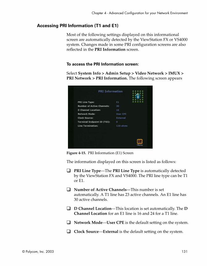
Chapter 4 - Advanced Configuration for your Network Environment
© Polycom, Inc. 2003 131
Accessing PRI Information (T1 and E1)
Most of the following settings displayed on this informational screen are automatically detected by the ViewStation FX or VS4000 system. Changes made in some PRI configuration screens are also reflected in the PRI Information screen.
To access the PRI Information screen:
Select System Info > Admin Setup > Video Network > IMUX > PRI Network > PRI Information. The following screen appears
Figure 4-15. PRI Information (E1) Screen
The information displayed on this screen is listed as follows:
❑ PRI Line Type—The PRI Line Type is automatically detected by the ViewStation FX and VS4000. The PRI line type can be T1 or E1.
❑ Number of Active Channels—This number is set automatically. A T1 line has 23 active channels. An E1 line has 30 active channels.
❑ D Channel Location—This location is set automatically. The D Channel Location for an E1 line is 16 and 24 for a T1 line.
❑ Network Mode—User CPE is the default setting on the system.
❑ Clock Source—External is the default setting on the system.

ViewStation FX/VS4000 User Guide
132 www.polycom.com
❑ Terminal Endpoint ID (TEI)—0 is used by default and cannot be edited.
❑ Line Termination (PRI E1 only)—Line termination is required when there is power to the system.
Setting up PRI Options (T1 and E1)
The PRI Setup screen lets you select the line signaling format, the switch protocol, the CSU mode, and the line build out (depending on the type of PRI that you have).
To access the PRI Setup screen:
Select System Info > Admin Setup > Video Network > IMUX > PRI Network > PRI Setup. The following shows PRI Setup screens for E1 and T1:
Figure 4-16. PRI Setup (E1) and PRI Setup (T1) Screens
Note
You can access the Advanced PRI Setup screen from this screen. For more information, refer to Setting Advanced PRI Options (E1 and T1).
The PRI setup information is generally obtained from the PRI service provider. You can configure the following options on this screen:

Chapter 4 - Advanced Configuration for your Network Environment
© Polycom, Inc. 2003 133
❑ Switch Protocol—Select your network switch protocol. For certain Asian countries, such as Japan, Hong Kong, Taiwan, NET5/CTR4 is also provided.
If you change the country settings, a new set of PRI switch protocols is loaded.
If the current switch protocol is no longer available, you will be prompted with “Do you wish to continue?” If you do, the current switch protocol will be changed to the default for the selected country. This will cause a reset of the PRI interface.
If more than one switch protocol is supported, you must find out from your telephone service provider which protocol to select.
The PRI network interface module originates and accepts data calls only and does not work with incoming PRI choice calls or non-PRI lines of any kind. Special services such as caller ID, blocking, and call forwarding are not supported.
❑ Line Signaling—Extended Super Frame (ESF)/Binary 8 Zero Substitution (B8ZS) are the default framing format and default line encoding format respectively. Legacy frame formats such as D4 are not supported.
❑ CSU (PRI T1 only)—By default, the T1 PRI network interface module is set for internal CSU mode.
If you prefer to use an external CSU, you must specify the following information in this screen:
1. In the CSU field, select External.
2. In the Line Buildout field, select the proper cable distance range that corresponds with the cable distance between the PRI interface and the external CSU.
Notes
For North America T1 only: connect an RJ-45 cable from the CPE equipment side of the external CSU to the PRI network interface module.For more information about the CSU, refer to PRI Technical Information in the Integrators’ Reference Manual for ViewStation EX, ViewStation FX, and VS4000.

ViewStation FX/VS4000 User Guide
134 www.polycom.com
❑ Line Build Out (PRI T1 only)—If you are using an internal CSU, enter the output attenuation in dB. If you are using an external CSU, enter the output attenuation in feet.
Selecting PRI Channels (E1 and T1)
You can limit the number of channels that a ViewStation FX or VS4000 can use to place or receive a call on the PRI Status screen. This screen lets you select the PRI channels that will be active for your PRI line.
To access the PRI Status screen:
Select System Info > Admin Setup > Video Network > IMUX > PRI Network > PRI Status. The following shows the T1 and E1 PRI Status screens:
Figure 4-17. PRI Status (T1) and PRI Status (E1) Screens
Note
This screen should only be handled by a knowledgeable network administrator.
To select a channel:
1. Use the arrow keys on the remote control. An active channel is represented by a green sphere and an inactive channel by a grey sphere.
Chapter 4 - Advanced Configuration for your Network Environment
© Polycom, Inc. 2003 135
2. Press the SELECT button on the remote control to change the status of the channel.
PRI Channel Selection Information
Outgoing Call. For an outgoing call, the ViewStation FX or VS4000 uses the first active and available channel starting with the lowest number from the channel range (1-23 for a PRI T1 and 1-30 for a PRI E1). If an additional channel is needed, the system chooses the next incremental number. For example, if channels 1 through 7 are inactive, but 8 is active and available, then 8 is the first channel that can be used by the ViewStation FX or VS4000 to place an outgoing call. If an additional channel is needed, the system will use the next available active channel in the range (which could be 9, and so on).
Incoming Calls. For incoming calls, the ViewStation FX or VS4000 may use the highest numbered channel in the range and, if needed, proceed to the next channel number in a descending order, depending on the type of third-party equipment attached to the system. For example, an incoming call arrives on channel 23, then 22, 21, and so on.
Dedicated full PRI T1 or E1 Line. All channels should be active for a full T1 or E1 line dedicated to your FX or VS4000.
Fractional PRI T1 or E1. Channel selection should be handled by your PRI network administrator.
PRI E1 Channel Information
The PRI Status screen (for E1) shows 30 channels. However, E1 trunk lines have 32 time slots, numbered 0 - 31. Time slot 0 is used for framing, and time slot 16 is used for call signaling (the D channel). The remaining 30 time slots are used as bearer (data) channels.
In call signaling between Polycom equipment and the switch, these channels are numbered 1-15, 17-31. But the PRI Status screen numbers these channels contiguously in the range 1-30. Therefore, on the PRI Status screen, channels 1-15 control the status of time slots 1-15, and channels 16-30 control the status of time slots 17-31.

ViewStation FX/VS4000 User Guide
136 www.polycom.com
Setting Advanced PRI Options (E1 and T1)
You can define several advanced PRI options for both T1 and E1 PRI network interface modules from the Advanced PRI Setup screen.
To access the Advanced PRI Setup screen:
Select System Info > Admin Setup > Video Network > IMUX > PRI Network > PRI Setup > Advanced PRI Setup.
Figure 4-18. Advanced PRI Setup Screen
The following information describes the options on the Advanced PRI Setup screen.
Caution
Do not change the default values without careful consideration. Determining the call-by-call value requires consultation with the telephone service provider.
❑ Restore Default—Selecting this option restores the default values to all of the fields on the Advanced PRI Setup screen.
❑ Numbering Plan—The two options, ISDN and Unknown, are described below:
• Unknown: The default selection is Unknown. With this option, the numbering plan and number type are sent to the upstream as unknown, and the dialed phone number is sent

Chapter 4 - Advanced Configuration for your Network Environment
© Polycom, Inc. 2003 137
without notification. Either the upstream switch or PBX is responsible for:
– Parsing the dialing string
– Interpreting any prefixes or access codes
– Determining whether the call is national or international
The default value, Unknown, is preferred and should work in most cases. Unknown should work with all properly configured PBXs and with most telephone company switches. One notable exception in North America is an ATT 5ESS switch, which is provisioned with Accunet, or an ATT 4ESS switch. For these switches, set the numbering type to ISDN.
• ISDN: If this option is selected, the numbering plan is identified to the upstream switch as ISDN, and the number type, which is either national or international, is determined from the dialed phone number. If the dialed phone number starts with the international dialing prefix that is currently selected, the type is set to the international and the prefix is removed from the number before the number is sent to the upstream switch. Otherwise, the number is marked as national and passed to the upstream switch without modification.
When ISDN is selected, the international dialing prefix is not recognized if any other access code or prefix precedes the international dialing prefix. The phone number must begin with the international dialing prefix.
❑ International Dialing Prefix—The international prefix defaults to 011 for North America and 00 for European countries. The default depends on the country. If you specify a numbering type or ISDN, the system searches for this value.
❑ Call-by-Call—Call-by-call is a number from 1 to 31, which is optionally sent to an upstream telephone company switch, if required. For example, specify a value of 6 for a T1 PRI network interface module that is directly connected to an ATT 5ESS switch, which is provisioned with Accunet. You must consult with the telephone company service provider to determine whether a call-by-call value is required for a particular PRI line.

ViewStation FX/VS4000 User Guide
138 www.polycom.com
For most cases, the default value of 0 is correct. Always use the value 0 when connected to a PBX. A non-zero value should not be required in Europe. Values greater than 31 are reserved for internal use and must not be used.
Setting Audio Quality Preference
In most cases, the default setting identified during the initial system setup will be adequate for quality audio. However, the settings can be changed based on specific bandwidth requirement in the Audio Quality Preference screen.
The Audio Quality Preference screen lets you set the call speed threshold that determines which audio protocol is used. At the selected speed or lower, the system uses the G.728 audio protocol. Above the selected speed, the system uses the G.722 audio protocol.
G.722 audio delivers higher quality audio, but uses 48 Kbps of the video bandwidth. G.728 delivers telephone quality audio and uses only 16 Kbps of the video bandwidth.
Note
For more information about the G.728, G.722, and G.722.1 audio protocols, refer to the Integrators’ Reference Manual for ViewStation EX, ViewStation FX, and VS4000.
To access the Audio Quality Preference screen:
Select System Admin > Admin Setup > Video Network > IMUX > Audio Quality.
To set your Audio Quality Preference:
Use the + and - buttons on the remote control to move the slider. Changing the audio bars has no effect during an H.320 call. Note that this screen is not accessible during an IP (H.323) call.

Chapter 4 - Advanced Configuration for your Network Environment
© Polycom, Inc. 2003 139
Figure 4-19 shows the Audio Quality Preference screen...
Figure 4-19. Audio Quality Preference Screen
Choosing the Number of Channels to be Dialed in Parallel
On this screen, you can define the number of ISDN channels to be dialed in parallel. By default, ISDN channels are dialed three at a time. On PRI systems, you can choose the number of channels to dial in parallel.
To access the Advanced Dialing screen:
Select System Info > Admin Setup > Video Network > IMUX > Advanced Dialing.
Figure 4-20. Advanced Dialing Screen
The number of channels to be dialed in parallel must be between 1 and 12. If you experience network problems dialing several channels simultaneously, you may want to decrease the number displayed on screen.

ViewStation FX/VS4000 User Guide
140 www.polycom.com
Selecting Dialing Speeds
The Dialing Speeds lets you limit the choices that appear as speed selections. Offering a minimum number of speeds is a way to lower network traffic. The speeds that are selected in this screen will be displayed as dialing speed selections in the Video Phone and in the Address Book screens.
To access the Dialing Speeds screen:
Select System Info > Admin Setup > Video Network > IMUX > Dialing Speeds.
Figure 4-21. Dialing Speeds Screen
To select dialing speeds:
1. Choose the appropriate dialing speeds.The default dialing speeds are 2 x 64 Kbps, 128 Kbps, 256 Kbps, 384 Kbps, 512 Kbps, and 768 Kbps.
2. To add or remove speeds, scroll through the data rates and press the SELECT button on the remote control to select your preferred dialing speeds; a red check appears when a dialing speed is selected.
The Nx56 and Nx64 columns list the dialing speeds available for ISDN calls.
The IPx56 and IPx64 columns list the dialing speeds available for IP calls.

Chapter 4 - Advanced Configuration for your Network Environment
© Polycom, Inc. 2003 141
Advanced Quad BRI Network Interface Configuration
This section describes information and settings for a series of BRI advanced configuration screens. These BRI configuration screens are:
❑ ISDN Video Numbers. See Entering ISDN Video Numbers, on page 141.
❑ Auto Detect Speed. See Entering or Detecting Service Profile Ids, on page 142.
❑ Audio Quality Preference. See Setting Audio Quality Preference, on page 144.
❑ Advanced Dialing. See Setting Channel Dialing Preferences, on page 145.
❑ Dialing Speeds. See Selecting Dialing Speeds, on page 146.
❑ ISDN Video Network. See Modifying ISDN Video Network Information, on page 147.
Note
For information about the initial BRI configuration screen, see Setup for the Quad BRI Network Interface on page 89.
Entering ISDN Video Numbers
Use the ISDN Video Number screen if you need to change the area code and ISDN (BRI) video numbers that you previously set up during the out-of-box configuration.
ViewStation FX/VS4000 User Guide
142 www.polycom.com
To access the ISDN Video Numbers screen:
Select System Info > Admin Setup > Video Network > IMUX > Numbers. The ISDN Video Numbers screen appears.
Figure 4-22. ISDN Video Numbers Screen
Your service provider should have given you these numbers when you purchased the ISDN line.
To enter information on this screen:
1. Press the arrow buttons on the remote control to move between fields on the screen.
2. Use the numeric keypad on the remote control to enter numbers in a highlighted field. To enter a dot, press the right arrow button on the remote control.
3. Highlight the Save icon and press the SELECT button on the remote control.
Entering or Detecting Service Profile Ids
The Service Profile Ids (SPIDs) can be configured manually or automatically detected by the system using the Auto Detect SPIDs screen.

Chapter 4 - Advanced Configuration for your Network Environment
© Polycom, Inc. 2003 143
To access the Auto Detect SPIDs screen:
Select System Info > Admin Setup > Video Network > IMUX > SPIDS. The Auto Detect SPIDs screen appears.
Figure 4-23. Auto Detect SPIDs Screen
Note
This screen appears only if you selected United States or Canada as your country on the country screen.
Entering the SPIDs manually. The SPIDs obtained from your network service provider can be entered manually on the Auto Detect SPIDs screen. If you are behind an internal phone system (PBX), you may not need to enter SPIDs.
Automatically detecting the SPIDs. If you do not have any SPID numbers, highlight the Start icon to have your system try to detect them automatically. This initiates a process that automatically detects the SPID numbers associated with your ISDN line. This process can take as long as ten minutes, but will usually require three minutes or less. If you are behind a PBX, select the PBX icon. Your system will try to locate the SPID numbers within the PBX.
If your system is unable to find your SPIDs, make sure that you are properly connected and that you have entered your ISDN numbers correctly.
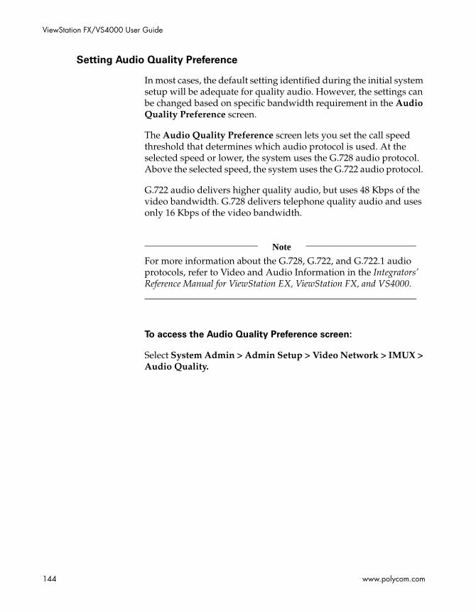
ViewStation FX/VS4000 User Guide
144 www.polycom.com
Setting Audio Quality Preference
In most cases, the default setting identified during the initial system setup will be adequate for quality audio. However, the settings can be changed based on specific bandwidth requirement in the Audio Quality Preference screen.
The Audio Quality Preference screen lets you set the call speed threshold that determines which audio protocol is used. At the selected speed or lower, the system uses the G.728 audio protocol. Above the selected speed, the system uses the G.722 audio protocol.
G.722 audio delivers higher quality audio, but uses 48 Kbps of the video bandwidth. G.728 delivers telephone quality audio and uses only 16 Kbps of the video bandwidth.
Note
For more information about the G.728, G.722, and G.722.1 audio protocols, refer to Video and Audio Information in the Integrators’ Reference Manual for ViewStation EX, ViewStation FX, and VS4000.
To access the Audio Quality Preference screen:
Select System Admin > Admin Setup > Video Network > IMUX > Audio Quality.
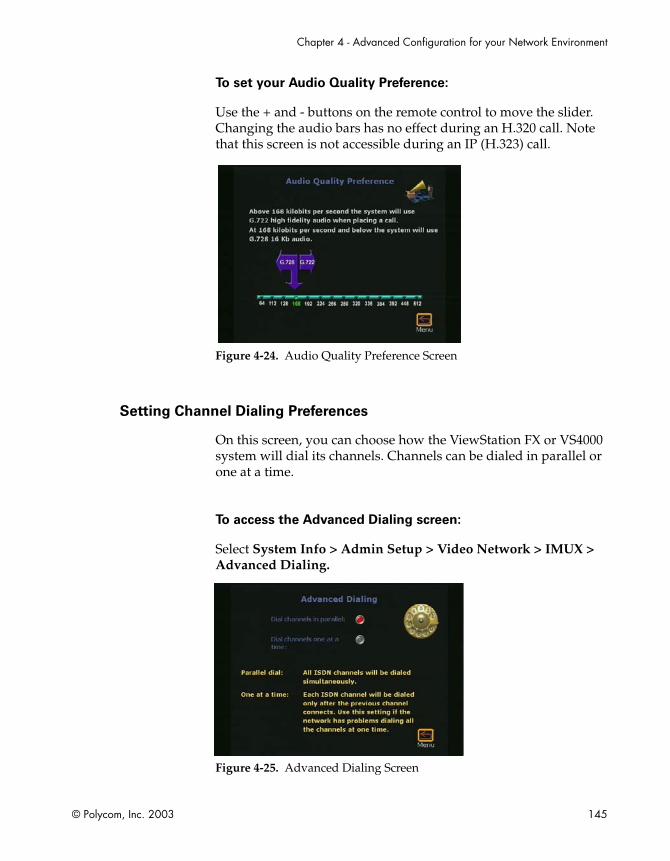
Chapter 4 - Advanced Configuration for your Network Environment
© Polycom, Inc. 2003 145
To set your Audio Quality Preference:
Use the + and - buttons on the remote control to move the slider. Changing the audio bars has no effect during an H.320 call. Note that this screen is not accessible during an IP (H.323) call.
Figure 4-24. Audio Quality Preference Screen
Setting Channel Dialing Preferences
On this screen, you can choose how the ViewStation FX or VS4000 system will dial its channels. Channels can be dialed in parallel or one at a time.
To access the Advanced Dialing screen:
Select System Info > Admin Setup > Video Network > IMUX > Advanced Dialing.
Figure 4-25. Advanced Dialing Screen

ViewStation FX/VS4000 User Guide
146 www.polycom.com
Select one of the following two options:
❑ Dial channels in parallel—All ISDN channels are dialed simultaneously. This is the default setting.
❑ Dial channels one a a time—Each ISDN channel is dialed after the previous channels has connected. Use this option if your network has problems dialing all the channels in parallel.
Selecting Dialing Speeds
The Dialing Speeds lets you limit the choices that appear as speed selections. Offering a minimum number of speeds is a way to lower network traffic. The speeds that are selected in this screen will be displayed as dialing speed selections in the Video Phone and in the Address Book.
To access the Dialing Speeds screen:
Select System Info > Admin Setup > Video Network > IMUX > Dialing Speeds.
Figure 4-26. Dialing Speeds Screen
The Nx56 and Nx64 columns list the dialing speeds available for ISDN calls.
The IPx56 and IPx64 columns list the dialing speeds available for IP calls.

Chapter 4 - Advanced Configuration for your Network Environment
© Polycom, Inc. 2003 147
To select dialing speeds:
1. Choose the appropriate dialing speeds.The default dialing speeds are 2 x 64 Kbps, 128 Kbps, 256 Kbps, 384 Kbps, 512 Kbps, and 768 Kbps.
2. To add or remove speeds, scroll through the data rates and press the SELECT button on the remote control to select your preferred dialing speeds; a red check appears when a dialing speed is selected.
Modifying ISDN Video Network Information
This screen allows you to modify the basic ISDN (BRI) options that were configured during the initial setup (see Setup for the Quad BRI Network Interface on page 89). These options are:
❑ Country Code—The Country Code is associated with the country where the ViewStation FX or VS4000 is used.
❑ Area Code—This is the area code or STD code used in the area where the system is located.
❑ Number A—This is the primary ISDN number assigned to the system.
❑ Number B—This is the secondary ISDN number assigned to the system.
❑ ISDN Switch Protocol—Select the appropriate ISDN switch protocols. Contact the ISDN provider to determine the ISDN switch protocol.
❑ ISDN Number Prefix—This prefix is used to access an outside line if the system is behind a PBX.

ViewStation FX/VS4000 User Guide
148 www.polycom.com
Configuration of the Global Address Book
Overview
This section describes how to configure the Global Address Book (GAB) on the ViewStation FX or VS4000 system.
Note
To use the GAB features, your organization must use Polycom Global Management System (GMS) software.
The Global Address Book configuration screens are accessible from the Global Address Book screen (System Info > Admin Setup > LAN/H.323 > Global Address). These screens are:
❑ Global Address (Server). See Configuring Settings for the Global Address Book Server, on page 149.
❑ Global Address Book Preferences and Advanced Address Book Preferences. See Setting the Global Address Book Preferences, on page 150 and Selecting the Call Type Order for OneDial Address Book Entries, on page 153.
The following screens are also available if you have a V.35/RS-449/RS-530, BRI, or PRI network interface attached to your the system.
❑ Dialing Rules 1. See Establishing Dialing Rules, on page 154.
❑ Dialing Rules 2. See Establishing Dialing Rules, on page 154.
The following screen is specific to a system with a Quad BRI or PRI network interface:
❑ Private Network Number. See Entering the Private Network Number, on page 154.

Chapter 4 - Advanced Configuration for your Network Environment
© Polycom, Inc. 2003 149
About the Global Address Book
The Global Address Book provides real-time directory services to let your system dial other ViewStation systems on your network, and other videoconferencing systems. The Global Address Book performs the following:
❑ Register systems automatically to the GAB server when they are powered up.
❑ Manage Address Book entries (dynamic and static addresses).
❑ Manage multiple Address Books.
❑ Support in-country and international dialing rules.
❑ Support ISDN and IP dialing.
The Global Address Book is part of the Global Management System (GMS). The GMS enables widespread deployment of conferencing systems by providing easy-to-use, centralized management, monitoring, and directory services to geographically distributed Polycom conferencing systems. For more information about the GMS, refer to the Integrators’ Reference Manual for ViewStation EX, ViewStation FX, and VS4000.
Configuring Settings for the Global Address Book Server
The Global Address screen allows you to enter the Global Address Book Server’s IP address and its password. It also lets you determine whether of not you want to use Global Addresses or register the system each time it is powered on.
To access the Global Address (Server) screen:
Select System Info > Admin Setup > LAN/H.323 > Global Address > Server.

ViewStation FX/VS4000 User Guide
150 www.polycom.com
Figure 4-27. Global Address (Server) Screen
You can configure the following GAB server options on this screen:
❑ Server IP Address—Enter the IP address of the GAB server.
❑ Server Password—Enter the GAB server password, if there is one.
❑ Global Directory Server Version—This displays the current version of the Global Directory.
❑ Display Global Addresses—When you enable this option, global addresses appear in the system’s Address Book.
❑ Register this System When Powered On—When you enable this option, the system's IP address appears in the GAB when the system registers with it. If you do not enable this option, the system has access to the GAB, but does not appear in the Global Address Books of other systems.
Setting the Global Address Book Preferences
The GAB display and dialing options available on this screen are determined by the call type options and the Use Gatekeeper option that you have previously enabled on the Call Preference and Gateway & Gatekeeper screens respectively.

Chapter 4 - Advanced Configuration for your Network Environment
© Polycom, Inc. 2003 151
To access the Global Address Book Preferences screen:
Select System Info > Admin Setup > LAN/H.323 > Global Address > Preferences.
Figure 4-28. Global Address Book Preferences Screen (for IP and ISDN Calls)
❑ Show Addresses in Address Book—This option lets you enable the types of video numbers you want to see in your Global Address Book. Only call type options that you enabled on the Call Preference screen (ISDN Video Calls, LAN/Internet Calls) appear on this screen.
This screen will also display the Gateway Calls option if you have previously enabled the Use Gatekeeper option in the Gateway & Gatekeeper screen.
When you enable the LAN/Internet Calls (H.323) option, IP addresses appear in the system’s Address Book.
❑ Maximum Line Speed for Global Addresses—You can set the line speed for each type of call you enabled in the Call Preference screen. Depending on your selection in the Call Preference screen, some or all of the following options are displayed on this screen:
• ISDN Video Calls
• International ISDN Calls
• LAN/Internet Calls
Gateway Calls is also displayed if you have previously enabled the Use Gatekeeper option in the Gateway & Gatekeeper screen.

ViewStation FX/VS4000 User Guide
152 www.polycom.com
The speeds you select affect only Global Address Book entries in the system’s Address Book.
❑ Preferred Alias (E.164)—This option is only available if you have registered your system with a Gatekeeper and the Global Address Book server. Select this field to access the Preferred Alias screen. See Selecting your Preferred Alias below.
Selecting your Preferred Alias
All the available options on this screen are valid numbers that outside systems can use to reach your ViewStation FX or VS4000 system. Select the number that you would like to register with the Global Directory Service.
To access the Preferred Alias screen:
Select System Info > Admin Setup > LAN/H.323 > Global Address > Preferences > Preferred Alias (E.164).
The options visible on the screen depend on the Gateway Number Type that you have previously selected on the Gateway Number screen.
❑ If DID is the Gateway Number Type that you selected on the Gateway Number screen, then the possible Preferred Alias options are:
• ISDN Number (if the system has ISDN natively)
• Full DID Number
• DID Number Provided by Switch
• DID Extension
• H.323 Extension
Note
For more information about DID, refer to Configuring the Gateway Number, on page 118.

Chapter 4 - Advanced Configuration for your Network Environment
© Polycom, Inc. 2003 153
❑ If Number + Extension is the Gateway Number Type that you selected on the Gateway Number screen, then the possible Preferred Alias options are:
• ISDN Number (if the system has ISDN natively)
• H.323 Extension
Selecting the Call Type Order for OneDial Address Book Entries
The Advanced Address Book Preferences screen lets you select the order of the call types (IP or ISDN) to use when you dial OneDial Address Book entries which contain both IP and ISDN numbers. For more information about OneDial, refer to Configuring the Gateway and Gatekeeper, on page 114.
To access the Advanced Address Book Preferences screen:
Select System Info > Admin Setup > LAN/H.323 > Global Address > Preferences> Advanced Preferences.
Two choices are available:
❑ Primary Call Type Choice—This option sets which call type the system will try first when dialing a site (which can be reached via IP and ISDN) from the Address Book. The choice can be ISDN or IP.
It is automatically reset to Manual if the setting matches that of the Secondary Call Type Choice. If both ISDN and LAN/Intranet are enabled, ISDN is the default.
If a call cannot be established using the primary call type, the system will use the secondary call type to automatically attempt to reconnect.
❑ Secondary Call Type Choice—This option sets which call type the system will try second when dialing a site (which can be reached via IP and ISDN) from the Address Book. The choice can be ISDN, IP, or None. It is automatically reset to None if the setting matches that of the Primary Call Type Choice. If both ISDN and LAN/Intranet are enabled, IP is the default.

ViewStation FX/VS4000 User Guide
154 www.polycom.com
Entering the Private Network Number
The Private Network ISDN (or PRI) Number provides a second number that can be used to call the ViewStation FX or VS4000 system (for example, the company’s PBX has two different lines coming from different network providers).It provides the correct numbers to the caller for the additional lines needed after the connection of the first line.
The Private Network Number can also be used to tell the PBX that additional calls should be routed internally within the PBX instead of going outside the PBX through the trunk line. In other words, the Private Network Number can be used as a “fake” number which the PBX handles as an internal number.
To access the Private Network ISDN (or PRI) Number screen:
Select System Info > Admin Setup > LAN/H.323 > Global Address > Private Net.
This screen is only accessible if a BRI or PRI network interface is attached to the system.The private number is generally obtained from the IT manager or the network administrator.
Note
Some PBXs always signal the same called number independent of which number was used to call an endpoint. The private number method might fail in this situation.
Establishing Dialing Rules
Dialing Rules 1
ViewStation FX or VS4000 numbers are automatically normalized for the address books of other ViewStation FX or VS4000 systems Global Dial takes into account the numbers, area codes (or city codes), country codes, and international dialing access codes for

Chapter 4 - Advanced Configuration for your Network Environment
© Polycom, Inc. 2003 155
systems that are placing and receiving calls. For example, if you live in Paris, your system’s number appears correctly in the address books of a system in Paris, a system in Sydney, a system in New York, and a system in Cape Town.
However, if your system is on your organization’s private network as well as a public network, you might have to add additional information that can help the Global Address Book (GAB) decide how you call other systems on or off your private network. If your system uses only a public network, you do not need to enter anything in this screen.
The Global Address Book uses the following dialing rules when calling a public network or a private network.
Table 4-1. Dialing rules used by the Global Address Book
These rules will be used by your Global Address Book server to provide your Address Book with the correct numbers to dial any site that is registered with your GAB. They are configured on the Dialing Rules 1 screen.
To access the Dialing Rules 1 screen:
Select System Info > Admin Setup > LAN/H.323 > Global Address > Dialing Rules 1.
Call From Call To Type of Call Placed
Public Network Public Network Public Network
Public Network Private Network Public Network
Private Network Public Network Public Network
Private Network Private Network Private Network

ViewStation FX/VS4000 User Guide
156 www.polycom.com
Figure 4-29. Dialing Rules 1 Screen
You can configure the following network dialing rules:
❑ Number of digits in Extension—Set the number of digits in your dialing extension. This usually applies to systems that are on a PBX. Sites that dial your system with the same area code (or city code) and prefix dial use only your extension number. For example, if your system’s number is 1 512 555 1212 and you set 5 as the number of digits in your extension, a system with the number 1 512 555 1212 will use 51212 to dial your system.
❑ International Dialing Prefix—Enter the prefix that must be used to place international calls. This prefix is automatically appended to any international calls made from the GAB. This overrides the international dialing prefix that is normally transparently set in the system Country screen.
❑ Public Network Access—Enable this option if your system can dial outside of your private network.
❑ Public Network Dialing Prefix—Enter a dialing prefix as required by your PBX to dial out to the public network. This prefix is automatically inserted before the dialing numbers to the public network from the GAB.
❑ Public Network (same area code) Prefix—Enter a prefix if one is required to call within the same area code.
❑ Private Network Access—Enable this option if your organization uses a private network for calls.

Chapter 4 - Advanced Configuration for your Network Environment
© Polycom, Inc. 2003 157
If both the caller and the called party are on your Private Network, as indicated by enabling the Private Network Access option, then the Address Book of the calling site (through the Global Directory Server) will show the private numbers of the site being called if they are entered in the Private Network ISDN (or PRI) Number screen (System Info > Admin Setup > LAN/H.323 > Global Address > Private Net). In other words, if both sites have the Private Network Access enabled, then their address books will show the other parties’ private numbers instead of the normal ISDN number.
For more information about Private Network ISDN (or PRI) Number, refer to Entering the Private Network Number, on page 154.
❑ Private Network Dialing Prefix—Enter the dialing prefix required to dial within your private network. This prefix is used if your system and the system you are calling have access to your organization’s private network.
Dialing Rules 2
If your private network requires you to dial prefixes to access certain area codes (or city codes), you can set those prefixes in the Dialing Rules 2 screen.
To access the Dialing Rules 2 screen:
Select System Info > Admin Setup > LAN/H.323 > Global Address > Dialing Rules 2. The following screen appears:
Figure 4-30. Dialing Rules 2 Screen

ViewStation FX/VS4000 User Guide
158 www.polycom.com
The prefix is dialed before the area code. For example, some sites require you to dial a 9 before dialing a 1-800-xxx-xxxx number.
Enable the Always Dial Area Code option if you must dial the area code to sites that have the same area code as your system. This is sometimes necessary for 10-digit dialing.

Chapter 4 - Advanced Configuration for your Network Environment
© Polycom, Inc. 2003 159
Configuration for the Global Management System
Overview
This section describes how to set up the ViewStation FX or the VS4000 system to be centrally configured, managed, and monitored by the Global Management System (GMS) server.
Note
To use the Global Management System (GMS) features, your organization must use Polycom Global Management System (GMS) software.
To access the Global Management screens:
Select System Info > Admin Setup > LAN/H.323 > Global Management. These screens are:
❑ Global Management. See Configuring Settings for the Global Address Book Server, on page 149.
❑ Global Management URLs. See Accessing Global Management Server URLs, on page 162
❑ Global Management Info. See Adding Global Management Technical Support Contact Information, on page 163
About Global Management System
The Polycom Global Management System (GMS) is a Web-based client/server software tool designed to enable and support centralized management of enterprise-wide video communications networks. GMS is used to:

ViewStation FX/VS4000 User Guide
160 www.polycom.com
❑ Manage and update a network of Polycom endpoints from your local desktop and minimize time spent maintaining video conferencing infrastructure.
❑ Obtain a global view of ViewStation systems connected to your network.
❑ Proactively and remotely identify when network errors and problems with ISDN lines or IP connections occur.
The GMS main features are:
❑ Centralized Video Network Management with Web-based Architecture—This tool allows you to maintain and manage the entire video communications network from any where in the world with your Web browser.
❑ Zero-Administration Directory Services—The enterprise-wide Global Directory enables users to dial any video system by name.
❑ Multiple Remote Alert Notification—The GMS’ proactive and reactive monitoring system automatically sends e-mail to multiple network administrators’ pagers with critical information enabling remote troubleshooting.
❑ Call Detail Record—Details of every video endpoint call is recorded into a database to be used later for customer bill-back or system expansion evaluation.
❑ Provisioning—GMS lets you create profiles of systems’ settings that can be sent to new installed systems.
❑ Multiple Security Permissions—You can create individual and group permission levels and access.
Note
For more information about GMS, refer to the Integrators’ Reference Manual for ViewStation EX, ViewStation FX, and VS4000. You can also find information on GMS on the Polycom Web site at www.polycom.com.
Chapter 4 - Advanced Configuration for your Network Environment
© Polycom, Inc. 2003 161
Setting Global Management Preferences
Global Management must be manually set on the ViewStation FX and VS4000 systems to be active.
To access the Global Management setup screen:
Select System Info > Admin Setup > LAN/H.323 > Global Management > Setup. The Global Management setup screen appears.
Figure 4-31. Global Management (Setup) Screen
You can set the following options on this screen:
❑ Allow Remote Monitoring—Enable this option to allow the GMS system administrator to view a call or view the room where the ViewStation FX or VS4000 camera is installed.
For privacy reasons, you can enable this option only from the near-site system. Also, if you want to protect your office privacy, disable this option.
❑ Time Difference from GMT—Enter the time difference from where the system is installed and Greenwich Mean Time (GMT). This allows the GMS to view the local time of the managed system.
❑ Daylight Savings Time—Enable this option if the area where the system is installed participates in Daylight Savings Time.
❑ Require Account Number to Dial—You must use GMS 2.0 or later to use this option. This feature is used to log calls to a
ViewStation FX/VS4000 User Guide
162 www.polycom.com
specific account so that they can be tracked and billed to the appropriate departments. When this option is selected, you cannot make a call without first entering an account number. This account number is saved in the GMS server database along with information specific to the call. Typically, the GMS administrator assigns the account number.
❑ Validate Account Number—This option is visible if the Require Account Number to Dial option is enabled. The account number is validated before the first call is attempted. The entry of a valid account number allows calls to be made for the next five minutes. After that, an account number must be re-entered. If you enter an account number, make a call, and then try to add a call more than five minutes later, you will again be prompted for an account number. If this account number is not valid, the pending call is not made and the call you had been in for the last five minutes is hung up. Account numbers are validated by the system whose IP address is the first entry in the GMS monitoring URLs list. If that IP address is incorrect or that system fails to respond, no calls can be made.
❑ Global Managers URLs (Select Server URLs)—Select this option to access the Global Managers URLs screen.
Accessing Global Management Server URLs
The Global Management URLs screen lists the GMS servers that remotely manage your system. When you are registered with the GMS, this information is automatically displayed on this screen. In some instances, you may add GMS server IP addresses manually. This information is provided by your network manager.

Chapter 4 - Advanced Configuration for your Network Environment
© Polycom, Inc. 2003 163
To access the Global Management URLs screen:
Select System Info > Admin Setup > LAN/H.323 > Global Management > Setup > Select Server URLs....The Global Management setup screen appears.
Figure 4-32. Global Management URLs Screen
The first field contains the address of the primary GMS server that performs account validation (see Validate Account Number on page 162).
The first entry in the GMS URLs list is used for account number validation. If you enter an incorrect IP address for the first entry, you will get "no response from GMS" if there is an attempt to validate an account number and you cannot make calls.
Adding Global Management Technical Support Contact Information
The Global Management Info screen allows you to enter the contact information of the person who administers GMS in the event assistance is requested by the user.

ViewStation FX/VS4000 User Guide
164 www.polycom.com
To access the Global Management Info screen:
Select System Info > Admin Setup > LAN/H.323 > Info 1. The following screen appears:
Figure 4-33. Global Management Info Screen
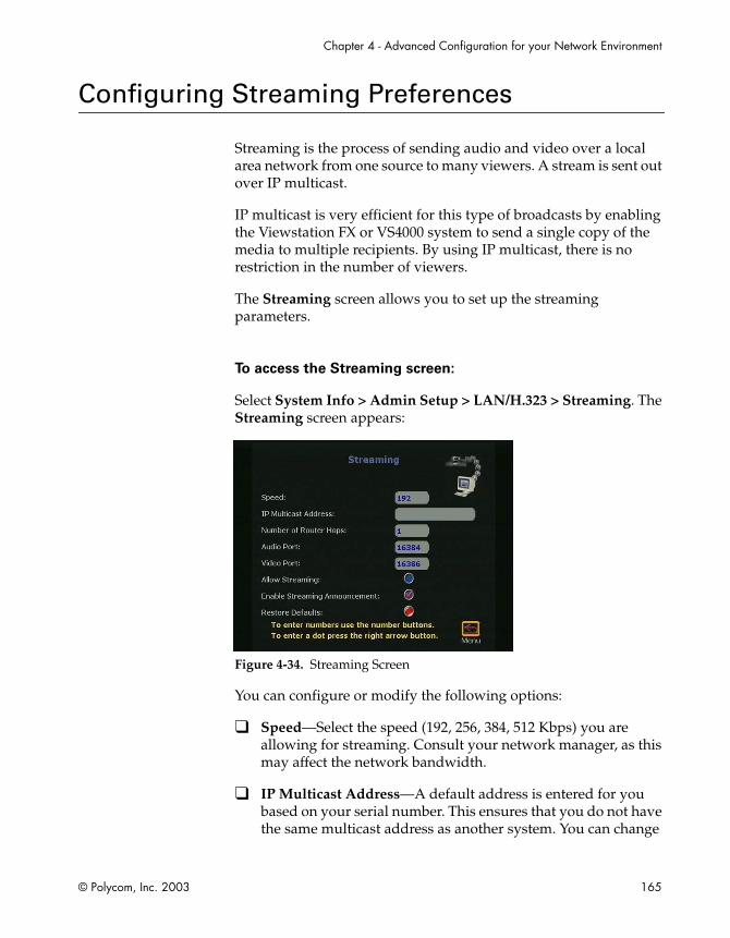
Chapter 4 - Advanced Configuration for your Network Environment
© Polycom, Inc. 2003 165
Configuring Streaming Preferences
Streaming is the process of sending audio and video over a local area network from one source to many viewers. A stream is sent out over IP multicast.
IP multicast is very efficient for this type of broadcasts by enabling the Viewstation FX or VS4000 system to send a single copy of the media to multiple recipients. By using IP multicast, there is no restriction in the number of viewers.
The Streaming screen allows you to set up the streaming parameters.
To access the Streaming screen:
Select System Info > Admin Setup > LAN/H.323 > Streaming. The Streaming screen appears:
Figure 4-34. Streaming Screen
You can configure or modify the following options:
❑ Speed—Select the speed (192, 256, 384, 512 Kbps) you are allowing for streaming. Consult your network manager, as this may affect the network bandwidth.
❑ IP Multicast Address—A default address is entered for you based on your serial number. This ensures that you do not have the same multicast address as another system. You can change

ViewStation FX/VS4000 User Guide
166 www.polycom.com
this address. This is the address of a relay server that unicasts the stream to multiple endpoints.
❑ Number of Router Hops—The number of router hops is officially called Time to Live or TTL. This value represents the number of routers the data can traverse before it is no longer passed on. A value of 1 specifies the multicast data stays within the subnet. A value of 2 means that a computer on a subnet which only has one router between it and the system will be able to play the stream.
❑ Audio Port—This is a fixed port. This may be changed by your network manager if a user needs to go through the firewall.
❑ Video Port—This is a fixed port. This may be changed by your network manager if a user needs to go through the firewall.
❑ Allow Streaming—When this option is enabled, the icon on the main screen of the user interface changes from Telephone to Call Type. Click Call Type to access the Streaming Call screen. In the Streaming Call screen, you can set a Meeting Password. Click the Start icon to start streaming.
❑ Enable Streaming Announcement—When this option is enabled, the names of users logged on to your system are displayed on screen.
❑ Restore Defaults—Selecting this option restores the Speed, IP Multicast Address, Number of Router Hops, Audio Port, and Video Port defaults.
To start streaming:
1. Go back to the main screen and select Call Type.
2. Select Streaming Call.
3. Enter a Meeting Password, if needed
4. Select Start.
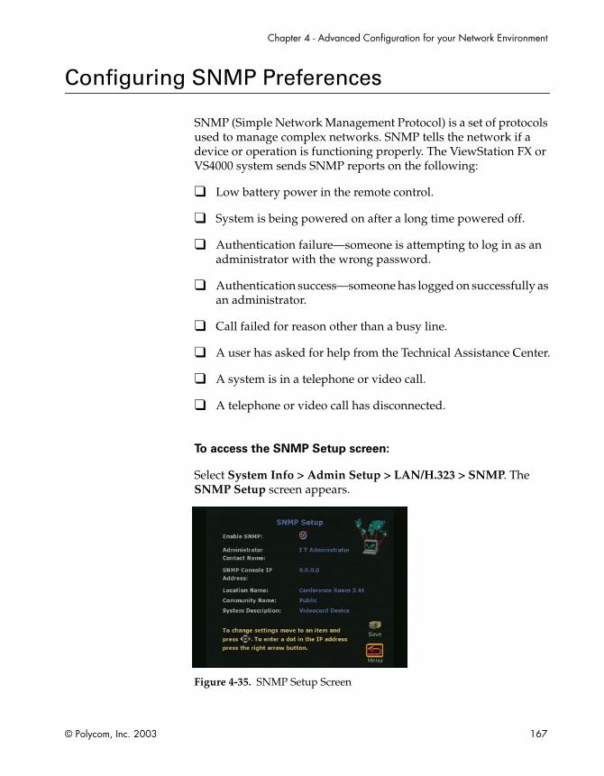
Chapter 4 - Advanced Configuration for your Network Environment
© Polycom, Inc. 2003 167
Configuring SNMP Preferences
SNMP (Simple Network Management Protocol) is a set of protocols used to manage complex networks. SNMP tells the network if a device or operation is functioning properly. The ViewStation FX or VS4000 system sends SNMP reports on the following:
❑ Low battery power in the remote control.
❑ System is being powered on after a long time powered off.
❑ Authentication failure—someone is attempting to log in as an administrator with the wrong password.
❑ Authentication success—someone has logged on successfully as an administrator.
❑ Call failed for reason other than a busy line.
❑ A user has asked for help from the Technical Assistance Center.
❑ A system is in a telephone or video call.
❑ A telephone or video call has disconnected.
To access the SNMP Setup screen:
Select System Info > Admin Setup > LAN/H.323 > SNMP. The SNMP Setup screen appears.
Figure 4-35. SNMP Setup Screen

ViewStation FX/VS4000 User Guide
168 www.polycom.com
You can enter the following information on the SNMP Setup screen:
❑ Enable SNMP—Enable or disable SNMP in this field.
❑ Administrator Contact Name—Enter the name of the person responsible for remote management of this system. The default setting for this field is “IT Administrator.”
❑ SNMP Console IP Address—Enter the IP address of the SNMP traps sent by the system. Enter 0.0.0.0 in this field if any SNMP management console is capable of receiving information from this agent.
❑ Location Name—Enter the location of the system. This field defaults to your system’s name@your country name.
❑ Community Name—Enter the SNMP management community in which you want to enable this agent. The default setting for this field is “Public.”
❑ System Description—This field displays the type of videoconferencing device. You cannot edit this field.

Chapter 4 - Advanced Configuration for your Network Environment
© Polycom, Inc. 2003 169
Configuring Quality of Service
The Quality of Service screen lets you select the type of service for your videoconferencing packets on your network and whether or not you would like to enable the Dynamic Bandwidth feature.
To access the Quality of Service and Firewalls screen:
Select System Info > Admin Setup > LAN/H.323 > QOS. The Quality of Service screen appears.
Figure 4-36. Quality of Service Screen
In this screen, you can configure the following options:
❑ Type of Service Field—Select one of the following two options:
• IP Precedence: This is a number that represents the level of priority given to IP packages sent to the ViewStation FX or VS4000 system. The value can be between 0 and 5. If this option is selected, enter the value in the Type of Service Value field.
• DiffServ: This is a number that also represents a priority level. The value can be between 0 and 63. If this option is selected, enter the value in the Type of Service Value field.
❑ Type of Service Value—Enter the value of the Type of Service Field option you have selected above (IP Precedence or Diffserv).

ViewStation FX/VS4000 User Guide
170 www.polycom.com
❑ Dynamic Bandwidth—Specify use of dynamic bandwidth allocation. The ViewStation FX and VS4000 systems’ dynamic bandwidth function automatically finds the optimum line speed for a call. If you experience excessive packet loss while in a call, the Dynamic Bandwidth function decreases the line speed until there is no packet loss. After some time with no packet loss, the dynamic bandwidth function incrementally increases line speed until packet loss occurs. At this point, the Dynamic Bandwidth function lowers the line speed one increment to ensure minimal packet loss with maximum throughput. This is supported in calls with end points that also support Dynamic Bandwidth.

© Polycom, Inc. 2003 171
5Using the
ViewStation FX/VS4000
This chapter explains how to perform all the basic system operations listed in the following Topics table.
Topics in This Chapter
The following topics are included in this chapter.
Topic Description Page
Remote Control
The remote control functions are explained in this section.
172
Video Calls This section explains how to place, answer, and end video calls.
176
Analog Telephone Calls
This section contains instructions on how to place a telephone call, add a telephone call to a video call and vice versa, and disconnect a telephone call.
186
Address Book This section describes how to add, edit, and delete Address Book entries. It explains how to transfer the Address Book from one system to another, how to use the Global Address Book, and how to create multipoint Address Book entries.
189
Cameras and Sound
This section describes how to control cameras and sound. It contains detailed information on camera settings, presets, and automatic tracking.
195
ViewStation FX/VS4000 User Guide
172 www.polycom.com
Remote Control
Most ViewStation FX or VS4000 functions are performed using the remote control. The remote control is an integral part of your system. It works very much like the remote control that you use at home for your television.
The remote control is an “intelligent” device: it becomes active as soon as you pick it up, and becomes inactive as soon as you set it down again.
You will use it to highlight and select icons that appear on the monitor connected to your system, configure your Address Book, adjust your camera, adjust the sound, place video calls, etc.
Snapshots This section explains how to send snapshots. It also contains information on the Snapshot Timeout option.
204
Picture-In-Picture (PIP)
This section describes the PIP feature (the picture from the local camera being displayed as a small picture on screen during an active video call).
206
Graphics Cursor
This section describes the graphics cursor and how to use it.
207
Topic Description Page

Chapter 5 - Using the ViewStation FX/VS4000
© Polycom, Inc. 2003 173
Figure 5-1. Remote Control
The remote control functionality is described in Table 5-1.
Table 5-1. Remote Control Functionality
Function Description
1. Call-Hangup Allows users to make calls or hang up call. It takes you to the dialing screen (Video Phone). It is used to place a call, to manually answer a call, to add in another video or audio endpoint call to a multipoint call.
2. Auto Activates, deactivates, and cycles through the auto-tracking functions.

ViewStation FX/VS4000 User Guide
174 www.polycom.com
3. Near Activates camera control of the near side of the call (your system). You know the near side function is activated when you see the camera icon in the top right corner of the screen pointing at you.
4. Far Activates camera control of the far side of the call (remote system), and also sets presets. You know the far side function is activated when the camera icon in the top right corner of the screen is facing away from you.
5. Slides Allows you to access preloaded slides or to start or stop a dual stream.
6. Arrow Buttons Allows you to navigate through the menu screens. The right arrow button is also used to enter a period (.) as in IP addresses.
7. Select The universal “enter” button. In most screens, you can press the SELECT button to select an icon, or to perform the function that you have highlighted.
8. Zoom Allows to zoom in and out of near and far PTZ (pan-tilt-zoom) cameras.
9. Snapshot Allows you to capture an image from the camera source of your choice and send it to the far side as a still image.
10. Mute Allows you to activate or deactivate the microphones on the near side using the remote control, as opposed to pressing the mute button on the microphone pod.
11. Volume Controls the volume of the sound through the amplifier in the system.
12. Keypad Used to enter dialing or screen configuration numbers. Also used to go to camera presets.
Function Description
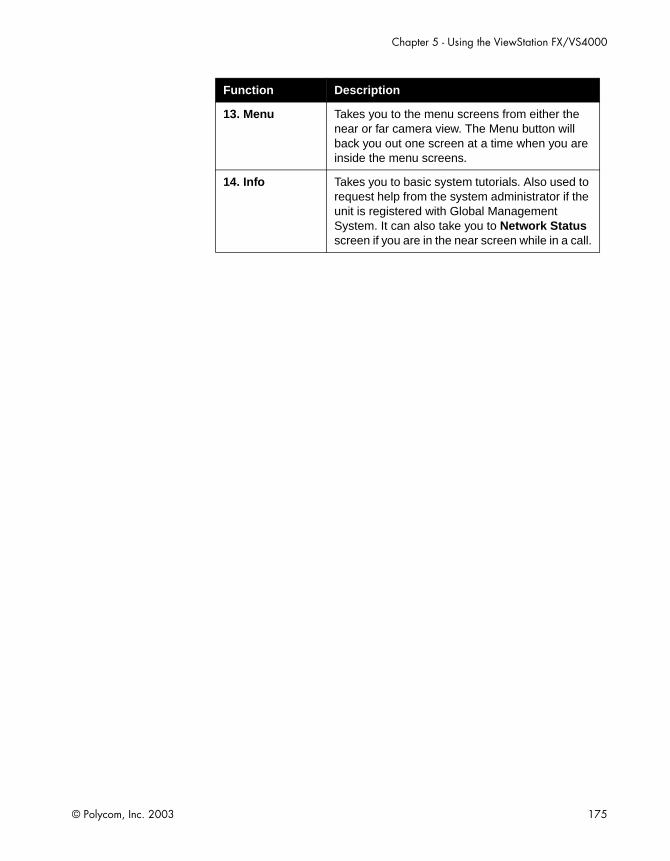
Chapter 5 - Using the ViewStation FX/VS4000
© Polycom, Inc. 2003 175
13. Menu Takes you to the menu screens from either the near or far camera view. The Menu button will back you out one screen at a time when you are inside the menu screens.
14. Info Takes you to basic system tutorials. Also used to request help from the system administrator if the unit is registered with Global Management System. It can also take you to Network Status screen if you are in the near screen while in a call.
Function Description

ViewStation FX/VS4000 User Guide
176 www.polycom.com
Video Calls
There are five ways to place a video call:
❑ Using manual dialing. See Placing a Call Manually.
❑ From the Address Book. See Placing a Call from the Address Book.
❑ Using speed dialing. See Placing a Speed-Dial Call.
❑ Dialing from the Web interface. See Placing a Call from the Web Interface.
❑ Dialing using the Application Programming Interface (API). See Placing a Call Using the Application Programming Interface.
Placing a Call Manually
Using One Number
To place a call manually using one number:
1. On the main screen, highlight the Video Call icon and press the SELECT button on the remote control. The following screen appears.
Figure 5-2. Video Phone Screen

Chapter 5 - Using the ViewStation FX/VS4000
© Polycom, Inc. 2003 177
2. Use the numeric keypad on the remote control to enter the number you want to dial.
If you need to enter alpha characters, press the AUTO button on the remote control to bring up the keyboard.
Note
When you enter a number using the remote control, you can hear a voice confirmation of that number from the ViewStation FX or the VS4000 system. This feature, Keypad Audio Confirmation, supports English, French, German, Portuguese, Spanish, and Chinese. It can be enabled on the General Setup screen by selecting the Keypad Audio Confirmation option.
3. Use the arrow buttons on the remote control to highlight the Speed icon on the screen and select the speed of your call from the list that appears.
4. Use the arrow buttons to navigate down to select the call type (AUTO, ISDN, or IP) and the desired call speed. If you select AUTO, the system will figure out automatically which call type to choose based on the format of the number you have entered.
5. Press the green CALL•HANG-UP button on the remote control to place your call. The number and the speed that you are dialing appear at the top of the screen.
The call progress indicators on the lower left side of the screen indicate that the call is going through.They change progressively to blue, yellow, orange, and green as your call completes.

ViewStation FX/VS4000 User Guide
178 www.polycom.com
Figure 5-3. Call Progress Indicators
6. When the call completes, the party you called appears on the screen, and you appear in the picture-in-picture (PIP) window at the lower right. If you have a two-monitor system, the party you are calling appears on the main monitor, and you appear on the second monitor.
If the call does not complete, an error message is displayed. If you receive an error message, press the INFO button on the remote control for an explanation. For V.35/RS-449/RS-530 systems, consult your DCE interface for error messages.
7. To end your call, press the CALL•HANG-UP button on the remote control. The following screen appears.
Figure 5-4. Call Hangup Choices Screen
8. Highlight the Disconnect Video Call icon and press the SELECT button on the remote control. If the call was made with

Chapter 5 - Using the ViewStation FX/VS4000
© Polycom, Inc. 2003 179
a number that is not in your Address Book, a dialog box gives you the opportunity to add the number. If you select Yes, the system takes you to the address book where you can enter the information. If you select No, the main screen appears on your monitor.
Notes
If you stay in this screen for 60 seconds without pressing the SELECT button on the remote control to stay in the call or hang up, the call is disconnected.
You can also place a video call using the Address Book or Speed Dial. For more information, see Address Book.
Using Two Numbers
In some instances, you need to dial ISDN numbers separately when the party that you are calling can only handle 2 x 56 Kbps or 2 x 64 Kbps speeds.
To manually place a video call using two numbers, complete
the following:
1. Select the Video Call icon. If the speed that you selected is for a 2 x 56 Kbps or 2 x 64 Kbps call, a second number field becomes visible. If the Auto H.323 option is enabled, the system knows which call type to use when dialing out based on the format of the number. If this option is not enabled, then the IP and ISDN options are visible on the Video Call screen and you need to select the appropriate option.
2. To enter the first ISDN number of the party you are calling, use the numeric keypad on the remote control.
To clear an entry, use the arrow buttons on the remote control to move the highlight box to the Clear icon on the screen, and press the SELECT button (or the CALL•HANG-UP button).
To clear part of an entry from the right, press the LEFT ARROW button once for each character you wish to delete.
3. To enter the second number:
ViewStation FX/VS4000 User Guide
180 www.polycom.com
• For an ISDN number one digit greater than the first, press the RIGHT ARROW button to enter that number, then skip to step 5.
• For an ISDN number which is the same as the first, press the DOWN ARROW button, then skip to step 4.
• Otherwise, press the DOWN ARROW button to move the orange highlight box to the second line of the screen. Use the LEFT ARROW button on the remote control to delete numbers to the left and the numeric keypad to enter the second ISDN number of the party you are calling.
4. Press the SELECT button (or the CALL•HANG-UP button) to place the call.
5. As the call connection approaches completion, the call progress indicators on the lower left of the screen change from blue to green. Two call progress indicators appear for each available line.
If the call cannot connect, an error box appears at the top center of the screen. You can re-dial from the Video Phone screen, where the number you entered will remain until it is replaced or the system is turned off.
When the call connects, the party you are calling appears in the main window and near-site video appears in a smaller screen at the lower right. If you are using a dual-monitor configuration, the party you are calling appears on the main monitor and you appear on the second monitor.
6. To end the call, press the CALL•HANG-UP button on the remote control, which takes you to the Call Hangup Choices screen.
7. Use the arrow keys to highlight the Disconnect Video Call icon and press the SELECT button on the remote control. If you highlight the icon but do not press SELECT, the call disconnects automatically after 60 seconds.
If the call was manually dialed with a number that does not appear in the Address Book, you are given an opportunity to enter the name and number from the call into the Address Book.
If you answer Yes, you will go to the screen used for adding a new entry to the Address Book. The number from that call is

Chapter 5 - Using the ViewStation FX/VS4000
© Polycom, Inc. 2003 181
already entered, and you can finish filling out the entry. If you answer No, the system returns to the main calling screen.
Placing a Call from the Address Book
You can place calls directly from your Address Book. For information on how to enter numbers into your Address Book, refer to Address Book.
You can place a call from the Address Book as follows:
1. Highlight the Address Book icon on the main screen and press the SELECT button. The Speed Dial screen appears.
Note
If the Display Speed Dial option has been disabled on the General Setup screen (page 2), you will access the Address Book directly.
2. Highlight the Address Book icon again and press the SELECT button.The Address Book screen appears. For each entry, the number is displayed along with icons showing dialing speed and if it is an H.320 (ISDN) or H.323 (IP) call.
Figure 5-5. Address Book Screen
3. Use the arrow buttons on the remote control to scroll through the list of names. Press the SELECT button when you find the entry you want. The system automatically begins to dial the video number.

ViewStation FX/VS4000 User Guide
182 www.polycom.com
Placing a Speed-Dial Call
Note
Speed Dial stores the last six numbers dialed from the ViewStation FX or VS4000 if the numbers are in your Address Book.If the Display Speed Dial option has been disabled on the General Setup screen (page 2), you will not have access to the Speed Dial screen, but you will be taken directly to the Address Book..
Figure 5-6. Speed Dial Screen
To place a Speed Dial call:
1. Highlight the Address Book icon on the main screen and press the SELECT button. The Speed Dial screen appears.
2. Highlight the speed dial entry you want to dial and press the SELECT button. The system automatically begins to dial the video number. You can also press the number of the speed dial entry you want to dial on your remote control. For example, to call speed dial entry 1, press 1 on the remote control.
To lock a Speed Dial entry:
You can lock a speed dial entry so that it always appears on the Speed Dial screen. This is useful for numbers you dial frequently.

Chapter 5 - Using the ViewStation FX/VS4000
© Polycom, Inc. 2003 183
1. To lock the number, highlight the entry on the Speed Dial screen.
2. Press the # button on the remote control. A Lock icon appears next to Speed Dial entries that are locked.
To unlock a Speed Dial entry:
1. To unlock a number, highlight the entry.
2. Press the * button on the remote control.
Placing a Call from the Web Interface
For instructions about how to place a video call from the Web interface, refer to Features of the Web Interface on page 257.
Placing a Call Using the Application Programming Interface
For instructions about how to place a call using the API, refer to the ViewStation EX, ViewStation FX, and VS4000 ARENA API Programmer’s Guide.
Answering a Video Call Manually
The ViewStation and the VS4000 systems are set by default to automatically answer incoming calls.
To set your system to answer video calls manually:
1. From the main screen, select System Info > Admin Setup > General Setup or select System Info > User Setup.
2. Highlight the field next to Auto Answer Point to Point, and select the No option from the drop-down menu.
3. When there is an incoming call, the user will be prompted with a message “You have a video call. Would you like to answer?” This message is followed by a video number and a far-site name

ViewStation FX/VS4000 User Guide
184 www.polycom.com
if they are available. If the user selects Yes, the call will be connected. If the user selects No, the call will be rejected.
Answering a Video Call Automatically
The ViewStation FX and the VS4000 systems are set by default to automatically answer incoming calls.If the default settings are changed, you can reset the system to answer calls automatically.
To set your system to answer video calls automatically:
1. From the main screen, select System Info > Admin Setup > General Setup or select System Info > User Setup.
2. Highlight the field next to Auto Answer Point to Point, and select the Yes option from the drop-down menu. Yes is the default.
3. Press the MENU button on the remote control until you return to the main screen.
If the Auto Answer Point to Point option is set to No, all video calls need to be answered manually. Refer to the preceding section for more information.
Setting the System to Do Not Disturb
To set your system to Do Not Disturb Mode:
1. From the main screen, select System Info > Admin Setup > General Setup or select System Info > User Setup.
2. Highlight the field next to Auto Answer Point to Point, and select the Do Not Disturb option from the drop-down menu.
3. With the Auto Answer mode set to Do Not Disturb, you will not be notified of any incoming call. The site which placed the call will receive either a “call rejected” or “dialed site busy” message.
Chapter 5 - Using the ViewStation FX/VS4000
© Polycom, Inc. 2003 185
Ending a Video Call
To end a video call:
1. To end your call, press the CALL•HANG-UP button on the remote control. The Call Hangup Choices screen appears.
2. Highlight the Disconnect Video Call icon and press the SELECT button or press the CALL•HANG-UP button on the remote control twice. If the call was made with a number that is not in your Address Book, a dialog box gives you the opportunity to add the number.
• If you select Yes the system takes you to the Address Book where you can enter the information.
• If you select No, the main calling screen appears on your monitor.
• To stay in the call, select the Stay in Call icon and press the SELECT button.
Note
If you stay in this screen for 60 seconds without pressing the SELECT button, the call automatically disconnects.

ViewStation FX/VS4000 User Guide
186 www.polycom.com
Analog Telephone Calls
In countries where it is approved, you can connect an analog telephone line to your ViewStation FX or your VS4000 system. This lets you make telephone calls through the ViewStation FX or the VS4000 system and include audio third parties in your video calls.
Placing a Telephone Call
You can use your system as a standard speakerphone.
To place a telephone call from your system:
1. From the main calling screen, select Telephone and press the SELECT button. The Telephone screen appears.
Figure 5-7. Telephone Screen
2. Use the numeric keypad on the remote control to enter the number you want to dial.
If you are dialing within your PBX system, you only have to dial the last four digits of the number.
If you want to delete a digit, press the LEFT ARROW button on the remote control.
To delete an entire phone number, highlight the Clear icon on the screen and press the SELECT button on the remote control.
3. Press the CALL•HANG-UP button on the remote control to place the call.
Chapter 5 - Using the ViewStation FX/VS4000
© Polycom, Inc. 2003 187
4. To end the call, press the CALL•HANG-UP button on the remote control.
Adding a Telephone Call to a Video Call
To add a telephone call once your video call is connected:
1. Press the CALL•HANG-UP button on the remote control. The Call Hang-up Choices screen appears.
2. Select the Add Speakerphone icon and press the SELECT button. The Telephone screen appears.
3. Enter the phone number of the third party using the numeric keypad on the remote control and press the SELECT button. The system begins dialing the third party.
4. Once the third party connects, press the NEAR or FAR button on the remote control to return to the videoconference.
Note
Three-way calling is only supported if you have enabled three-way calling from your local telephone company. Select the FLASH button on the telephone screen to obtain another line.
Disconnecting a Telephone Call
To disconnect a telephone call:
1. Press the CALL•HANG-UP button on the remote control. The Call Hang-up Choices screen appears.
2. Select the Disconnect Speakerphone Call icon and press the SELECT button on the remote control. The third party disconnects.
ViewStation FX/VS4000 User Guide
188 www.polycom.com
Adding a Video Call to a Telephone Call
To add a video call once your telephone call is connected:
1. Press the MENU button on the remote control until you reach the main calling screen.
2. Highlight the Video Call icon and press the SELECT button on the remote control. The Video Phone screen appears.
3. Use the numeric keypad on the remote control to enter the number you want to dial.
If you are dialing within your PBX system, you only have to dial the last four digits of the number.
To delete a digit, press the left arrow button on the remote control.
To delete an entire phone number, highlight the Clear icon on the screen and press the SELECT button on the remote control.
4. Press the CALL•HANG-UP button on the remote control to place the call.
5. To end the call, press the CALL•HANG-UP button on the remote control.

Chapter 5 - Using the ViewStation FX/VS4000
© Polycom, Inc. 2003 189
Address Book
The Address Book saves you time by allowing you to place video calls by name. You can pre-program up to 1,000 entries in the Address Book. The Address Book supports both single site or multi-site calls, depending upon system configuration.
If your organization uses Polycom's Global Management System™ software, you can configure your Address Book to automatically show all of the addresses used in your organization.
For information on how to place a call from the Address Book, refer to Placing a Call from the Address Book in this chapter.
To access the Address Book:
1. Select the Address Book icon on the main screen. The Speed Dial screen appears.
2. Highlight the Address Book icon again and press the SELECT button on the remote control. The main Address Book screen appears as follows.
Figure 5-8. Address Book Screen
From this screen, you can perform all Address Book tasks.

ViewStation FX/VS4000 User Guide
190 www.polycom.com
Note
The New, Edit, and Delete icons are only visible if the Allow Address Book Changes option has been enabled in the General Setup screen (System Info > Admin Setup > General Setup).
Adding an Entry to the Address Book
To add an entry to the Address Book:
1. Select the Address Book icon on the main screen. The Speed Dial screen appears.
2. Highlight the Address Book icon again and press the SELECT button on the remote control. The main Address Book screen appears.
3. Highlight the New icon and press the SELECT button on the remote control. The New Address Book Entry screen appears.
4. Highlight the One Site icon and press the SELECT button on the remote control. The Add/Change Entry screen appears.
Figure 5-9. Add/Change Entry Screen
5. Use the on-screen keyboard and the remote control to enter the necessary information on this screen.

Chapter 5 - Using the ViewStation FX/VS4000
© Polycom, Inc. 2003 191
Tip
Enter a dot. To enter a dot, press the right button on the remote control.Shift key settings. The on-screen keyboard’s Shift key has three settings:- lower case: using the remote control, select the Shift key until it turns into a greyish down arrow.- upper case: using the remote control, select the Shift key until it turns into a green up arrow (as shown on Figure 5-9). Only the next letter you enter is capitalized.- caps lock: select the Shift key twice. A lock symbol appears on the key. All the letters are capitalized while the lock is visible.
6. If you are using OneDial, enter both the ISDN VIdeo Number and the IP Video Number. OneDial is a Polycom proprietary feature that greatly simplifies videoconferencing dialing through taking care of a number of dialing and network processes in the background. For more information about OneDial, refer to About Polycom OneDial.
7. Highlight the Save icon and press the SELECT button on the remote control. You then return to the main Address Book screen.
Note
To create a multi-site entry, refer to Creating Multipoint Address Book Entries.
Editing an Existing Entry in the Address Book
To edit an existing Address Book entry:
1. Use the UP and DOWN arrow buttons on the remote control to highlight an Address Book entry.

ViewStation FX/VS4000 User Guide
192 www.polycom.com
2. Highlight the Edit icon and press the SELECT button on the remote control. The Add/Change Entry screen and the on-screen keyboard appear.
3. Use the on-screen keyboard and the remote control to change the information on this screen as needed.
In the name field, use the backspace key on the on-screen keyboard to delete letters.
In the number field, use the LEFT ARROW button to delete numbers.
4. Highlight the Save icon and press the SELECT button on the remote control. Your changes are saved and you return to the main Address Book screen.
Note
You cannot edit Global Address Book entries. They are dynamically obtained from the ViewStation FX or the VS4000 system that is logged into the Global Address Book (GAB) server.
Deleting Entries in the Address Book
To delete entries in the Address Book:
1. Highlight the entry you want to delete.
2. Use the left arrow button to highlight the Delete icon.
3. Press the SELECT button on the remote control. The entry you selected is now deleted from the Address Book.
Transferring the Address Book
You can transfer the contents of your ViewStation FX or your VS4000 system’s Address Book to a far-site ViewStation system while in an ISDN call (Address Book transfers can occur between all ViewStation models).
Chapter 5 - Using the ViewStation FX/VS4000
© Polycom, Inc. 2003 193
To transfer the contents of your Address Book:
1. From the main calling screen, go to System Info > Admin Setup > Software/Hardware.
2. Click the Send Address Book icon.
3. Enter the Administrator Password and Software Update Security Password of the far-site ViewStation system.
4. Click the Start icon to begin the transfer.
Note
This feature is only available when the system is in an ISDN call to a single endpoint.
Using the Global Address Book
If your organization uses Polycom's Global Management System software and your ViewStation FX or your VS4000 system is set to subscribe to the Global Address Book server, you can access global addresses.
The Global Address Book provides users with easy, one-button dialing to anywhere in the world. The Global Address Book automatically captures and updates your system’s dialing information, country codes, and preferred line speeds. The user simply selects a name from the list to place a call.
When you access the Address Book on a system that subscribes to the Global Address Book server, you see addresses that have been entered manually and global addresses from various address books.
The following icons on the Address Book screen indicate Global Address Book status and individual address status.
The presence of this icon in the upper right corner indicates that the system is connected to the Global Address Book server. When this icon rotates, it indicates that the system is actively accessing the Global Address Book server for addresses. Notice the icon rotating as you scroll through the address list.

ViewStation FX/VS4000 User Guide
194 www.polycom.com
For more information about Global Management System software, go to our Web site at www.polycom.com or see About Global Management System on page 159.
Creating Multipoint Address Book Entries
You can make it easier to place multipoint video calls by creating multipoint entries in your Address Book. Multipoint entries are made with the single-site entries that are already listed in your Address Book or Global Address Book. When you use multipoint entries, you can call all the selected sites from one Address Book entry.
For information about creating a multipoint entry and placing a multipoint call, refer to Using an Address Book Meeting Entry on page 218.
This icon indicates that the selected address is an address from the Global Address Book. You cannot edit or delete global addresses from your system. You can perform these tasks only from the Global Address Book console.
This icon allows you to save a global entry to your local Address Book.
This icon indicates that the selected address is an address that was entered manually. These addresses are local to your system and are not reported to the GAB server. You can edit and delete these addresses from your system.
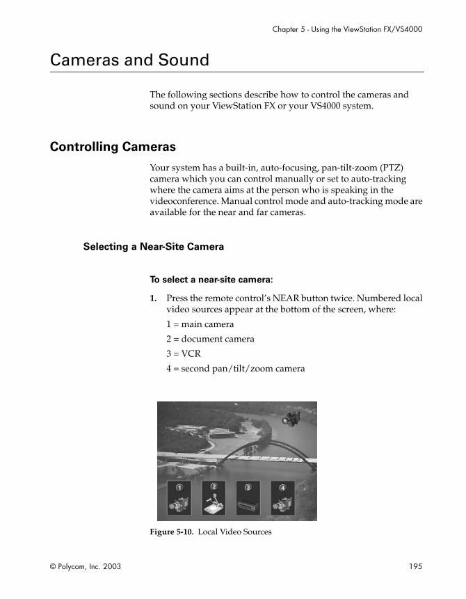
Chapter 5 - Using the ViewStation FX/VS4000
© Polycom, Inc. 2003 195
Cameras and Sound
The following sections describe how to control the cameras and sound on your ViewStation FX or your VS4000 system.
Controlling Cameras
Your system has a built-in, auto-focusing, pan-tilt-zoom (PTZ) camera which you can control manually or set to auto-tracking where the camera aims at the person who is speaking in the videoconference. Manual control mode and auto-tracking mode are available for the near and far cameras.
Selecting a Near-Site Camera
To select a near-site camera:
1. Press the remote control’s NEAR button twice. Numbered local video sources appear at the bottom of the screen, where:
1 = main camera
2 = document camera
3 = VCR
4 = second pan/tilt/zoom camera
Figure 5-10. Local Video Sources

ViewStation FX/VS4000 User Guide
196 www.polycom.com
2. Use the left or right arrow keys on the remote control to highlight a video source. Then press the SELECT button on the remote control.
-or-
After pressing the NEAR button twice on the remote control, press button 1, 2, 3, or 4 to jump to a specific camera.
Note
Make sure that the camera icons are displayed on screen. Otherwise, when you press the number button, a camera preset will be selected instead of a different camera source.
3. The system displays full screen the camera’s current view on the television monitor. A Camera icon appears in the upper right corner pointing towards you.
Selecting a Far-Site Camera
To select a far-site camera source during a call:
1. Press the FAR button twice on the remote control. A series of cameras pointing away from you (towards the far site) appears.
2. Press the left or right arrow key on the remote control to highlight a video source. Then press the SELECT button on the remote control.
-or-
After pressing the FAR button twice, press button 1, 2, 3, 4, or 5 to jump to a specific camera.
3. Press the SELECT button on the remote control.
4. The system displays full screen the far-site camera’s current view on the television monitor. A Camera icon appears in the upper right corner pointing away from you.

Chapter 5 - Using the ViewStation FX/VS4000
© Polycom, Inc. 2003 197
Note
If there is no camera connected to the selected video source, you will see either a blue screen or frozen video from the last video source.
Controlling the Near-Site Camera
Camera Control Mode—To control or adjust the camera on your system, press the NEAR button on the remote control. A camera icon appears in the upper right corner pointing towards you.
Tilt, Pan—Use the arrow buttons on the remote control to tilt the camera up and down and to pan from side to side.
Zoom—Use the ZOOM buttons to zoom in and out.
The following picture shows the buttons that are used on the remote control to control the camera.
Figure 5-11. Camera Control Button on Remote Control
Controlling the Far-Site Camera
You can also adjust the camera on the far site in a call if that site has its Far Control of Near Camera option enabled. Other sites can control the camera on system if you have this option enabled.

ViewStation FX/VS4000 User Guide
198 www.polycom.com
To enable the Far Control of Near Camera option on your
system:
Select System Info > Admin Setup > Video/Camera > Cameras.
To put the camera in control mode:
To control or adjust the system’s camera on the far site, press the FAR button on the remote control. The far site camera's view appears full screen on the television monitor. A Camera icon appears in the upper right corner pointing away from you. Use the remote control to adjust the far-site camera the same way you would adjust your camera.
To tilt or pan the camera:
Use the arrow buttons on the remote control to tilt the camera up and down and to pan from side to side.
To zoom:
Use the ZOOM buttons on the remote control to zoom in and out.
To go to a menu screen while in a call:
While in a call, if you have to go to a menu screen to make some adjustments, pressing the NEAR or FAR button on the remote control returns you to your call view.
Adjusting a Second Camera
If you have a second pan/tilt/zoom camera connected to your system, you can adjust it with the remote control also.
To adjust a second camera:
1. Press the NEAR button twice. Icons appear for all of the connected local cameras.

Chapter 5 - Using the ViewStation FX/VS4000
© Polycom, Inc. 2003 199
2. Highlight the icon for the second camera and press the SELECT button on the remote control.
Adjusting Camera Settings
You can adjust the settings of your cameras from the Cameras screen.
To access this screen:
Select System Info > Admin Setup > Video/Camera > Cameras.
The options available on the Cameras screen are described in the section Video and Cameras Screens on page 333.
Setting Camera Presets
You can set and store up to ten preset camera positions. These ten camera presets can be distributed across the far camera and up to four near-site cameras.
To set a camera preset:
1. Press the NEAR or FAR button on the remote control to select the near or far camera.
2. If you pressed the NEAR button, press it again to select the near-site camera.
3. Position the camera using the arrow buttons and ZOOM buttons on the remote control.
4. Press the SELECT button on the remote control. The camera preset circles are now displayed. A “Press 0-9 to store a preset” message appears on the main monitor.
Notes
If the circle is transparent, the preset is empty.
If the circle is solid yellow, the preset is assigned.
ViewStation FX/VS4000 User Guide
200 www.polycom.com
To clear all the presets, press the pound (#) key on the remote.
5. Press a number button on the remote control to assign that button to the preset.
6. To select a camera preset, press the NEAR or FAR button for the desired camera and press the number button on the remote control for the preset you want.
Enabling Automatic Voice Tracking (ViewStation FX Only)
The main camera on your ViewStation FX system can automatically move to whomever is speaking in the meeting. The first time the camera moves to a person, it might take several seconds of continuous speech to locate the person speaking.
The camera picks out the position quickly the next time the person speaks. Automatic voice tracking mode uses the built-in hypercardiod microphones in the set-top unit (instead of using the microphone pods) to triangulate the location of the current speaker and aim the camera at that person. If the person moves or another person speaks, the camera will retriangulate and re-aim the camera.
Note
The speed and the accuracy of automatic voice tracking largely relies on the quality of the acoustics and the amount of ambient noise in the room. In some situations, triangulation of the speaker may take longer than expected.
To enable automatic voice tracking:
Press the AUTO button once on the remote control. A Camera icon with a motor attached appears in the upper right corner of the main monitor.

Chapter 5 - Using the ViewStation FX/VS4000
© Polycom, Inc. 2003 201
To turn off automatic voice tracking:
Pan, tilt, or zoom the camera. Any of these actions returns the camera to manual mode.
Note
The VS4000 system does not support automatic voice tracking.
Enabling Automatic Tracking to Camera Presets (ViewStation FX Only)
Automatic tracking to camera presets also triangulates the location of the speaker, but aims the camera at the closest camera preset to the location of the speaker. This is effective if the meeting participants are sitting or are otherwise stationary.
Note
The system senses the frequency range of the human voice. Therefore, the camera will not aim at noises outside of that frequency range, such as pencil tapping, coughing, or whistling.
To enable automatic tracking to camera presets:
1. Select the far or near camera and press the AUTO button twice to enable automatic tracking to preset positions.
2. The camera moves to the preset nearest to the person speaking.
To disable automatic tracking to camera presets:
Move the selected camera using the ARROW buttons on the remote control.
Automatic camera tracking is temporarily disabled under the following conditions:

ViewStation FX/VS4000 User Guide
202 www.polycom.com
❑ When your site is on MUTE.
❑ When there are loud noises coming from the far site or when the far site is speaking.
❑ When the near site moves the camera.
Note
This feature is not available on the VS4000 system.
Controlling Sound
Setting the Volume
The volume of the ViewStation FX or the VS4000 system is related to the volume on the television monitor.
To set the volume:
1. Set the volume on the television monitor to one-half its maximum volume.
2. Set the system’s volume at a comfortable hearing level.
3. To adjust the volume on the system, press the VOL (Volume) buttons on the remote control.
Using the Mute Button
The mute button on the microphone pod is used to prevent far-site participants from hearing your conversation.
To activate the MUTE function:
Press the MUTE button on the remote control or on the microphone pod. Notice that the red light on top of the microphone pod is illuminated.

Chapter 5 - Using the ViewStation FX/VS4000
© Polycom, Inc. 2003 203
The Mute icon appears in the bottom left corner of the television monitor indicating to the near and far sites that mute is turned on. This mute indicator feature is supported in ISDN and IP calls. However, the mute indicator for IP calls is only supported by Polycom endpoints.
Controlling Sound Effects Volume
There is a separate volume control for the sound effects on the ViewStation FX and the VS4000 system.
To adjust this volume setting:
1. Select System Info > Admin Setup > Phone/Audio.
2. Select the Sound Effects Volume field.
3. Adjust the volume setting by using the volume control buttons on the remote control.
ViewStation FX/VS4000 User Guide
204 www.polycom.com
Snapshots
This section explains how to send snapshots to the far site and how to use the Snapshot Timeout feature.
Sending Snapshots
You can send a snapshot from any local camera to the participants in a videoconference by using the snapshot feature on the ViewStation FX or the VS4000 system.
To send a snapshot to meeting participants:
1. Press the SNAPSHOT button on the remote control.
2. Select a camera. Refer to Controlling Cameras for more information about selecting cameras.
3. Position the camera as necessary.
4. Press the SNAPSHOT button on the remote control again. The image is seen by all of the far sites in a call.
5. To preview your snapshot before sending it, press the SNAPSHOT button once and press 1, 2, or 3 for your desired camera source. You see a live preview from the selected camera while the far site still sees you.
6. To send the image, press the SNAPSHOT button again.
Snapshot Timeout
By default, all slides and snapshots are displayed for a period of four minutes. When the display times out after four minutes, the system automatically returns to live video. However, when this option is disabled, the snapshot or slide stays on screen indefinitely until the user presses the SNAPSHOT button on the remote control to return to live video.

Chapter 5 - Using the ViewStation FX/VS4000
© Polycom, Inc. 2003 205
To disable the Timeout feature:
1. Select System Info > Admin Setup > Video/Camera > TV Monitors.
2. In the TV Monitors screen, disable Snapshot Timeout.
Note
Both sites must have disabled the Snapshot Timeout option for this feature to work. If one side has not disabled Snapshot Timeout, the system reverts to its default settings.

ViewStation FX/VS4000 User Guide
206 www.polycom.com
Picture-In-Picture (PIP)
On a single monitor system, the picture from the local camera is always displayed as a small picture (a PIP) in the lower right corner of the screen during an active video call.
To swap the main and PIP images on a single monitor system:
1. Press the NEAR and SELECT buttons on the remote control.
2. Use the icon button on the screen to swap the main and PIP images.
On a dual monitor system, the second monitor always has the picture from the local camera, except when viewing a snapshot or presentation. After 15 seconds, the local video appears in a PIP window.

Chapter 5 - Using the ViewStation FX/VS4000
© Polycom, Inc. 2003 207
Graphics Cursor
The Graphics Cursor is an arrow (pointer) that you can display and move around on a slide. The cursor is a convenient way to point to a specific item or area of the slide while you are talking about the item or area.
General Information
The graphics cursor is available only in slide/snapshot viewing mode and works on any slide that has been received from:
❑ Someone pressing the SNAPSHOT button on the remote control
❑ A Microsoft PowerPoint presentation
❑ PolycomSnap
Note
The cursor is not available in preview mode.
The graphics cursor is displayed only for the current slide; that is, the slide that is displayed when you activate the cursor. If you go to another slide, the cursor is not displayed. You must display the cursor again.
You can use the graphics cursor on a graphics monitor or VGA monitor. The cursor is available only on a dual-monitor or multi-monitor system, not a single-monitor system using your main monitor only.
Any party in the video call that is viewing the slide can manipulate the graphics cursor. In addition, all parties can see the cursor as long as one site has displayed the cursor.

ViewStation FX/VS4000 User Guide
208 www.polycom.com
Using the Graphics Cursor
Displaying the graphics cursor. Press one of the numbers (1-9) on the remote control. The graphics cursor appears as a yellow arrow. The cursor is displayed for 30 seconds and then disappears from the screen.
To redisplay the cursor, press the number 5, which allows you to turn the graphics cursor on and off.
Moving the graphics cursor. You can move the graphics cursor around the screen and point to any specific object. You can move the cursor left and right, up and down, and diagonally.
Table 5-2 summarizes each graphics cursor function associated with a specific numeric button on the remote control.
Table 5-2. Graphic cursor function and remote control
Number on the Remote Control Graphic Cursor Function
1 Moves the cursor diagonally up and to the left.
2 Moves the cursor up.
3 Moves the cursor diagonally up and to the right.
4 Moves the cursor to the left.
5 Toggles to display and not display the cursor.
6 Moves the cursor to the right.
7 Moves the cursor diagonally down and to the left.
8 Moves the cursor down.
9 Moves the cursor diagonally down and to the right.

© Polycom, Inc. 2003 209
6Using Advanced System
Features
This chapter describes how to configure and use advanced ViewStation FX and VS4000 features.
Topics in This Chapter
The following topics are included in this chapter.
Topic Description Page
Multipoint Calls This section contains detailed information on the following multipoint features:
• multipoint dialing speed and firewall
• the different methods that can be used to place multipoint video calls
• Mixed Protocol Dialing feature
• viewing modes
• passwords
• cascading capabilities
• chair control
• four-monitor support
211
Dial-In Calling The Dial-In Calling feature lets users who are already in a videoconference answer and add an incoming video call. This section covers information about the number of calls combinations, and also explains how to set the Auto Answer mode for a multipoint call.
234

ViewStation FX/VS4000 User Guide
210 www.polycom.com
Conference on Demand (COD)
This feature allows you to bring multiple endpoints together in a videoconference on an unscheduled basis. Its implementation is covered in this section.
237
Streaming Video
This section contains instructions about how to enable streaming and view streams using Apple QuickTime.
240
Data Conferencing
This section explains how to enable data conferencing on the ViewStation FX or VS4000 system and how to use the ShowStation® IP, StreamStation™, and Microsoft NetMeeting.
244
People+Content This section gives an overview of this dual streaming feature.
246
Topic Description Page

Chapter 6 - Using Advanced System Features
© Polycom, Inc. 2003 211
Multipoint Calls
When there are more than two parties participating in a video call, it is called a multipoint call. You can have up to four parties participating in a call with the ViewStation FX or the VS4000 system.
If you have a PRI or BRI network interface, you can place multipoint calls over a PRI or BRI line or over IP (H.323) on the LAN. If you have a V.35/RS-449/RS-530 network interface, you can place multipoint calls only over IP on the LAN.
Before you Begin
Multipoint Dialing Speed Table
The following table shows the maximum allowable dialing speeds according to the number of sites in a call. All parties in a multipoint call must be connected at the same speed.
Table 6-1. Multipoint Dialing Speeds
Network Interface
Number of Sites in a Call
Maximum Speed For Each Party in the Call(in Kbps)
ISDN(H.320) IP (H.323)
V.35/RS-449/RS-530
234
1472 1920512384
PRI 22
34
1472 (T1)1920 (E1)512384
19201920512384

ViewStation FX/VS4000 User Guide
212 www.polycom.com
Mixed Protocol Dialing Speed Table
The following table shows the maximum allowable dialing speeds according to the number of calls and the type of calls (ISDN and IP) in a multipoint videoconference.
All parties in a multipoint call must be connected at the same speed. A multipoint videoconference can mix both IP and ISDN calls. For more information, see Mixed Protocol Dialing, on page 221.
BRI 2 with 2 lines 2 with 3 lines2 with 4 lines
3 with 2 lines3 with 3 lines3 with 4 lines
4 with 2 lines4 with 3 lines4 with 4 lines
256384512
128192256
64128128
192019201920
512512512
384384384
IP (H.323) Only Refer to H.323 speeds in this table.
Network Interface
Number of Sites in a Call
Maximum Speed For Each Party in the Call(in Kbps)
ISDN(H.320) IP (H.323)

Chapter 6 - Using Advanced System Features
© Polycom, Inc. 2003 213
Table 6-2. Mixed Protocol Dialing Speeds
Multipoint Downspeeding
When necessary, the ViewStation FX or VS4000 system is able to downspeed calls, meaning that it can dynamically reduce the data rate of the call to accommodate incoming calls. For example, if there is an existing point-to-point conference at 384 Kbps and an endpoint calls into the conference at 128 Kbps, the conference systems will downspeed the 384 Kbps call to 128 Kbps so that all the sites are connected at 128 Kbps. Conversely, incoming IP and ISDN calls dialed at speeds greater than the current conference speed are
Network Interface
Number of Endpoints and Type of Calls
Maximum Speed For Each Party in the Call(in Kbps)
ISDN(H.320) IP (H.323)
PRI with Mixed Protocols (ISDN and IP)
With any combination of ISDN and IP calls:
2234
1472 (T1)1920 (E1)512384
19201920512384
BRI with Mixed Protocols (ISDN and IP)
2 lines with:
1 ISDN + 1 IP
2 ISDN + 1 IP
2 IP + 1 ISDN
3 lines with:
1 ISDN + 1 IP
2 ISDN + 1 IP2 IP + 1 ISDN
4 lines with:
1 ISDN + 1 IP2 ISDN + 1 IP
2 IP + 1 ISDN
256
128
256
384
192384
512256
384
256
128
256
384
192384
512256
384

ViewStation FX/VS4000 User Guide
214 www.polycom.com
negotiated down to the current conference speed and admitted into the conference (rate matching).
However, if one of the systems cannot downspeed, the conference is kept at the original data rate, while the incoming call keeps its own data rate. The system with the lower data rate can send and receive audio. It can also send video, but cannot receive video. For example, if a system that is not capable of downspeeding connects at 384 kbps, the conference proceeds at 384 Kbps and admits the new endpoint at 128 Kbps. The 128 Kbps endpoint will be able send and receive audio. It can also send video, but it cannot receive video. It can only see its own video instead.
Note
To indicate that a particular endpoint which cannot downspeed at the correct data rate is admitted to the multipoint call as an audio call only, the ViewStation FX or VS4000 MCU displays a picture of a telephone in the screen area corresponding to that endpoint call.
Downspeeding calls, either IP or ISDN, to allow another endpoint to be added to an existing call (Dial-In Calling) is supported for mixed protocol calls with systems that are capable of downspeeding. For more information about inbound calls, refer to Dial-In Calling, on page 234. For mixed protocol calls, see Mixed Protocol Dialing, on page 221.
For a 2 or 3-way conference, the maximum allowable downspeeding rate is 512 Kbps. For a 4-way conference, the maximum allowable downspeeding rate is 384 Kbps.
Downspeeding/Resynchronization Compatibility
Downspeeding or Resynchronizing with iPower
Your system has the ability to downspeed or resynchronize correctly in an H.320 call with an iPower system and vice versa. The two systems resynchronize the call if an ISDN line is lost during the call. The call downspeeds in the event of a lower-speed, incoming
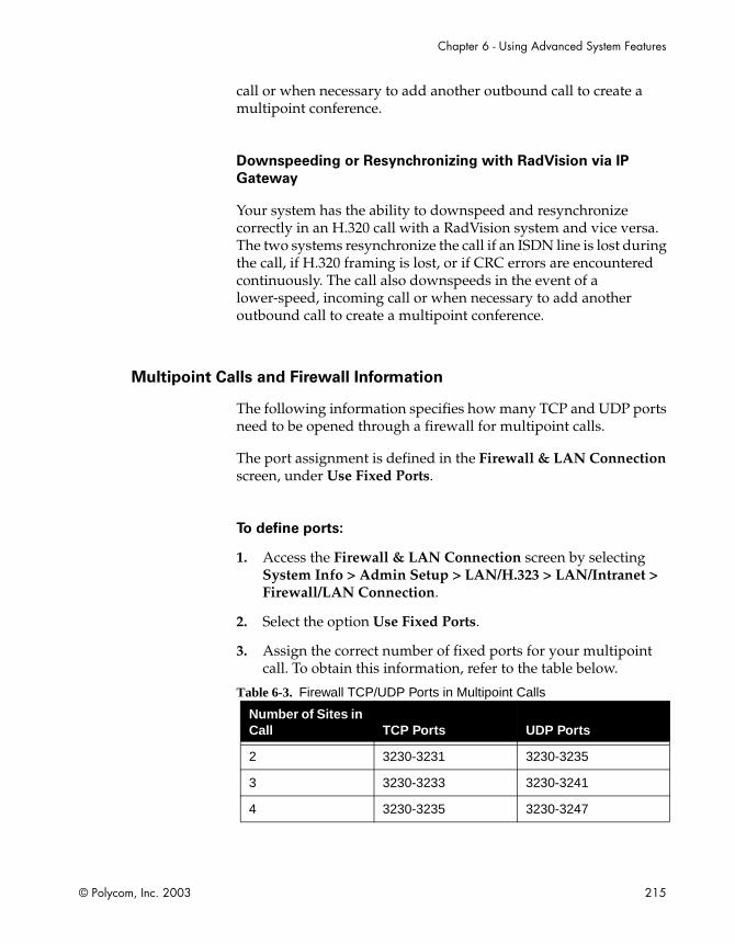
Chapter 6 - Using Advanced System Features
© Polycom, Inc. 2003 215
call or when necessary to add another outbound call to create a multipoint conference.
Downspeeding or Resynchronizing with RadVision via IP
Gateway
Your system has the ability to downspeed and resynchronize correctly in an H.320 call with a RadVision system and vice versa. The two systems resynchronize the call if an ISDN line is lost during the call, if H.320 framing is lost, or if CRC errors are encountered continuously. The call also downspeeds in the event of a lower-speed, incoming call or when necessary to add another outbound call to create a multipoint conference.
Multipoint Calls and Firewall Information
The following information specifies how many TCP and UDP ports need to be opened through a firewall for multipoint calls.
The port assignment is defined in the Firewall & LAN Connection screen, under Use Fixed Ports.
To define ports:
1. Access the Firewall & LAN Connection screen by selecting System Info > Admin Setup > LAN/H.323 > LAN/Intranet > Firewall/LAN Connection.
2. Select the option Use Fixed Ports.
3. Assign the correct number of fixed ports for your multipoint call. To obtain this information, refer to the table below.
Table 6-3. Firewall TCP/UDP Ports in Multipoint Calls
Number of Sites in Call TCP Ports UDP Ports
2 3230-3231 3230-3235
3 3230-3233 3230-3241
4 3230-3235 3230-3247
ViewStation FX/VS4000 User Guide
216 www.polycom.com
Placing Multipoint Video Calls
There are several ways to place multipoint video calls:
❑ Using the user interface’s Manual Dialer (Video Phone). See Using the Manual Dialer (Video Phone).
❑ Using a multi-site local Address Book Meeting entry. See Using an Address Book Meeting Entry.
❑ Adding existing Address Book entries one at a time. See Using the Address Book.
❑ Using a combination of Manual Dialer and Address Book entries. See Using the Manual Dialer and the Address Book.
Using the Manual Dialer (Video Phone)
The following explains how to place a multipoint call manually by adding sites to your videoconference.
To place the first call:
a. On the main screen, highlight the Video Call icon and press the SELECT button on the remote control.
b. Use the numeric keypad on the remote control to enter the number you want to dial in the highlighted field.
Note
When you enter a number using the remote control, you can hear a voice confirmation of that number from your system. This feature can be enabled on the General Setup screen by selecting the Keypad Audio Confirmation option.
If you need to enter alpha characters, press the AUTO button on the remote control to bring up the on-screen keyboard.
Chapter 6 - Using Advanced System Features
© Polycom, Inc. 2003 217
Tip
Enter a dot. To enter a dot, press the right button on the remote control.Shift key settings. The on-screen keyboard’s Shift key has three settings:- lower case: using the remote control, select the Shift key until it turns into a greyish down arrow.- upper case: using the remote control, select the Shift key until it turns into a green up arrow. Only the next letter you enter is capitalized.- caps lock: select the Shift key twice. A lock symbol appears on the key. All the letters are capitalized while the lock is visible.
c. Use the arrow buttons on the remote control to highlight the Speed icon on the screen and select the speed of your call from the list that appears.
d. Use the arrow buttons on the remote control to highlight the call type field (ISDN, IP, or AUTO). Press the SELECT button on the remote control to toggle and select the proper call type. If you select AUTO, the system will figure out automatically which call type to choose based on the format of the number you have entered.
e. Press the green CALL•HANG-UP button on the remote control to place your call. The number and the speed that you are dialing appear at the top of the screen.
The call progress indicators on the lower left side of the screen indicate that the call is going through.They change progressively from gray to blue, yellow, orange, and green as your call completes.
f. When the call completes, the party you called appears on the screen, and you appear in the picture-in-picture (PIP) window at the lower right. If you have a two-monitor system, the party you are calling appears on the main monitor, and you appear on the second monitor.
ViewStation FX/VS4000 User Guide
218 www.polycom.com
To add sites to your video call:
a. Press the CALL•HANG-UP button on the remote control. The Call Hang-up Choices screen appears.
b. Highlight the Add a Video Call icon and press the SELECT button on the remote control. The Video Phone screen appears.
c. Enter the number you want to dial or use Speed Dial in the Address Book or Address Book entry. Press the CALL•HANG-UP button on the remote control to place the call. The video call connects.
d. Repeat steps a through c until all of the sites are connected.
Using an Address Book Meeting Entry
The following explains how to create a multipoint Address Book meeting entry and place a multipoint call using that entry.
If you delete one of the single-site entries that make up one of your multipoint meeting entries, the single-site (multipoint) entry is automatically removed from your Address Book meeting entry.
To create a multipoint Address Book meeting entry:
1. Highlight the New icon in the Address Book and press the SELECT button on the remote control. The New Address Book Entry screen appears.
2. Highlight the Multi-Site icon and press the SELECT button on the remote control. The Multi-Site Meeting screen appears
3. Use the on-screen keyboard to enter a name for the meeting.
4. Highlight the Add icon to add parties to your call from the Address Book. The Adding To Meeting screen appears.
5. Highlight the entry you want to add and press the SELECT button on the remote control. The multipoint Address Book entry screen appears with that entry added.
6. Repeat Steps 4 and 5 until you have entered all of the sites for the call.

Chapter 6 - Using Advanced System Features
© Polycom, Inc. 2003 219
7. If the site being added is a OneDial number (meaning that it has both IP and ISDN numbers displayed as one entry), the user can change the call type of the individual entry by selecting the appropriate type in the Type field.
8. Select a dialing speed for the call in the Speed field. All of the sites in the call will be dialed at this speed regardless of the dialing speeds set for the individual Address Book entries.
9. Highlight the Save icon and press the SELECT button on the remote control to return to the main Address Book screen.
To place a multipoint meeting call from the Address Book:
1. Select the multipoint meeting entry you created in the Address Book.
2. Press the CALL•HANG-UP button. All of the sites are called automatically.

ViewStation FX/VS4000 User Guide
220 www.polycom.com
Using the Address Book
The following explains how to place a multipoint call by adding existing local or Global Address Book sites one at a time.
To place the first call:
1. Select the Address Book icon on the main screen and press the SELECT button on the remote control. The main Address Book screen appears.
2. Highlight the first site name and select it with the remote control SELECT button.
3. If the Address Book entry for that site is not a OneDial number (both IP and ISDN numbers displayed as a single entry), the number is being dialed.
If the Address Book entry is a OneDial number, then the call is dialed based on the Primary Call Type Choice option (Admin Setup > LAN/H.323 > Global Address > Preferences > Advanced Preferences). If the primary call type is IP, then the IP number is dialed. If the primary call type is Manual, a dialog box appears asking you to select either IP or ISDN. Highlight the appropriate protocol and select it with the SELECT button on the remote control. The site number is automatically dialed.
To add sites to your video call:
1. Press the MENU button on the remote control to go back to the main screen.
2. To add subsequent sites, repeat steps 1 through 3 from the above section describing how to place the first call until all sites are connected.
Using the Manual Dialer and the Address Book
This method is a combination of Manual Dialer and Address Book dialing. Refer to Using the Manual Dialer (Video Phone), on page 216 and to Using the Address Book, on page 220.
Chapter 6 - Using Advanced System Features
© Polycom, Inc. 2003 221
Mixed Protocol Dialing
Mixed Protocol Dialing allows users with IP (H.323) and ISDN (H.320) systems to participate in a multipoint videoconference at the same time. With this feature, videoconferencing is not limited to either H.320-only calls or H.323-only calls. All calls are connected at the same speed. Currently, downspeeding is automatically performed when necessary.
Mixed Protocol Dialing takes advantage of OneDial by allowing endpoints to dial your system by name from the Global Address Book without having to worry about which number to dial or which dialing protocol to use. For more information about OneDial, refer to the Integrators’ Reference Manual for ViewStation EX, ViewStation FX, and VS4000.
Different Ways to Place a Mixed Protocol Call
A Mixed Protocol call can be placed in one of the following five ways using the ViewStation user interface:
❑ Using the Manual Dialer (Video Phone screen). With this method, the user establishes the first call, then adds a second, and possibly a third call. The Manual Dialer allows the user to select IP or ISDN. For more information about how to place this type of call, refer to Using the Manual Dialer (Video Phone), on page 216.
❑ Creating an Address Book meeting entry. This entry consists of mixed ISDN and IP sub-entries. The user can decide what type of call will be made when creating or editing the entry. For more information about how to place this type of call, refer to Using an Address Book Meeting Entry, on page 218.
❑ Using the Global Address Book. The user establishes the first call, adds a second, and maybe a third call using the Global Address Book. If the selected entry is a OneDial number, make sure the Primary Call Type Choice option on the Advanced Address Book Preferences screen (Admin Setup > LAN/H.323 > Global Address > Preferences > Advanced Preferences) is configured to be Manual. Every time an additional call is added, the user is prompted with the message “dialing IP or ISDN”. If the selected entry is not a OneDial number, the

ViewStation FX/VS4000 User Guide
222 www.polycom.com
Primary Call Type does not affect how calls are made. For more information about how to place this type of call, refer to Using the Address Book, on page 220.
❑ Using a combination of Manual Dialer and Global Address Book. Establish the first call, then add a second and a third call using the Manual Dialer and the Global Address Book. For more information about how to place this type of call, refer to Using the Manual Dialer and the Address Book, on page 220.
❑ Through Dial-In Calling. A mixed protocol call can also be created if the user is already in a point-to-point call (IP or ISDN) and the user receives an incoming call that uses the other protocol (IP or ISDN). For more information about the Dial-In Calling feature, refer to the following section Dial-In Calling, on page 234.
Additional Information
Supported ViewStation FX and VS4000 Functionality
❑ Dual streams functionality when using Visual Concert FX is supported in mixed protocol calls.
❑ Downspeeding calls, either H.323 or H.320, to allow another endpoint to be added is supported for mixed calls with systems that are capable of downspeeding.
❑ PowerPoint presentations, snapshots, PolycomSnap, and interoperability with Visual Concert PC are supported in mixed protocol calls.
❑ Far-end camera control is supported in presentation or full-screen mode with Polycom endpoints in mixed protocol calls.
❑ Audio (POTS) add-ins are supported in mixed protocol calls.
❑ All multipoint modes are supported in mixed protocol calls.
❑ Chair control is supported in mixed protocol conferences.

Chapter 6 - Using Advanced System Features
© Polycom, Inc. 2003 223
Current Limitations
❑ Once an H.323 endpoint is added to a bridge call, any open T.120 sessions from H.320 calls will be terminated. T.120 is not supported in mixed bridge calls.
❑ In a 336-Kbps multipoint call between an H.320 and an H.323 systems, the H.320 system transmits and receives 30 frames per second. However, because of the flow control threshold, the H.323 system can only transmit 15 frames, but it can still receive 30 frames.
Multipoint Viewing Modes
You can select four different viewing modes for the remote sites in a multipoint call from the Multipoint Setup screen:
❑ Automatic Mode
❑ Discussion Mode
❑ Presentation Mode
❑ Full Screen Mode
To access the Multipoint Setup screen:
On a system with IP only, select System Info > Admin Setup > Multipoint Setup or select System Info > User Setup > Multipoint Mode.
On a system with an ISDN network interface, select System Info > Admin Setup > Video Network > Multipoint Setup.
Mode Description
The default mode is Auto, which switches between Discussion and Presentation modes automatically, depending on the conversational style of your meeting.

ViewStation FX/VS4000 User Guide
224 www.polycom.com
Following is a description of the four multipoint modes and the Auto Answer Multipoint setting:
❑ Auto—In Auto mode, the system determines the optimal viewing mode based on the interaction between the sites. If more than one site is talking at the same time, the system uses Discussion mode.
If one site is talking uninterrupted, the system uses Presentation mode. The system takes about 15 seconds to decide whether there is a single presenter before switching to Presentation mode. If one of the far sites interrupts the presenter for several seconds during Presentation mode, the system immediately switches to Discussion mode.
❑ Discussion—In Discussion mode, all of the sites can see everyone in the meeting at the same time. This feature is sometimes referred to as Continuous Presence mode. You see yourself as one of the sites. Your picture might be slightly delayed if you are in a multipoint call. This is normal. The far sites hear your voice synchronized with your motion.
If you are using a single-monitor system, sites appear on screen in as many windows as there are sites in the call. If you are using a dual-monitor system in a four-way call, the near site (you) appears in the second television monitor and the far sites appear in windows on the first television monitor. If you are using a dual-monitor system in a three-way call, each far site appears full screen on each monitor and the near site appear in PIP window on the main monitor.
❑ Presentation—In Presentation mode (also called voice-activated switching), the person who is speaking appears full screen to the far sites. If you are using a single-monitor system, the speaker or presenter appears full screen on your monitor.
Your picture automatically appears in a PIP window when you raise your remote control. If you are using a dual-monitor system, the person speaking appears in the main monitor, and the other parties appear in windows on the second monitor.
❑ Full Screen—In Full Screen mode, every site in the call sees the speaker full screen.
❑ Auto Answer Multipoint—This setting is used to determine how the system will handle an incoming call in a multipoint
Chapter 6 - Using Advanced System Features
© Polycom, Inc. 2003 225
videoconference. This setting only matters if the system is in a call.
Select the appropriate option from the drop-down menu in the Auto Answer Multipoint field. These options are No, Yes, and Do Not Disturb and are described below.
• No: If Auto Answer Multipoint is set to No and there is an incoming call, the user will be prompted with a message “You have a video call. Would you like to answer?" This message can be followed by a far-site video number and a far-site name if they are available. If the user selects Yes, the call will be added into the ongoing conference. If the user selects No, the call will be rejected. The factory default is set to No.
• Yes: If Auto Answer Multipoint is set to Yes, any incoming call will be connected automatically. The screen will split into a multipoint call progress screen as the incoming call is answered.
• Do Not Disturb: If Auto Answer Multipoint is set to Do Not Disturb, the user is not notified of the incoming call. The site which placed the call receives a Far Site Busy code (H.320) or Call Rejected (H.323).
Switching Modes
To switch multipoint meeting modes:
1. From the main calling screen, select System Info > User Setup.
Note
If you are switching modes during a multipoint call, press the MENU button on the remote control to go to the main calling screen.
2. Select the MP Mode field. The Multipoint Setup screen appears.
3. Select Auto, Discussion, Presentation, or Full Screen mode.

ViewStation FX/VS4000 User Guide
226 www.polycom.com
4. Press the MENU button on the remote control until you return to the main screen.
Multipoint Conference Password
A multipoint conference password is sometimes required for calls dialed into your MCU or dialed out to a third-party MCU. Your system can be configured to send or set the Meeting Password as the multipoint conference password to the MCU.
The Meeting Password works with the ViewStation FX or VS4000 system’s embedded MCU and other external bridges that support meeting passwords.
Setting Up the Meeting Password
To set the Meeting Password as your multipoint conference
password:
1. From the main screen, select System Info > User Setup (or System Info > Admin Setup > Security).
2. In the User Setup screen, under Meeting Password, enter your password.
Your configured Meeting Password is automatically and transparently sent as the multipoint conference password to the multipoint conference.
Using the Meeting Password
The Meeting Password can be used for the following purposes:
❑ To provide dial-in protection for the ViewStation FX or VS4000 MCU. If dial-in password protection has been set on the MCU, all the sites dialing into that MCU need to provide a password in order to join the videoconference. Refer to MCU Meeting Password Protection in Multipoint Dial-In Calls on page 228.

Chapter 6 - Using Advanced System Features
© Polycom, Inc. 2003 227
❑ To be able to dial into an MCU or a bridge that has a password set (see above item). The site calling into the MCU needs to send the established Meeting Password to the MCU.
❑ To view slides on the Web interface. Refer to Viewing a Slide Presentation on page 266.
❑ To view a meeting/stream on the Web interface. Refer to Viewing a Meeting on page 268.
❑ To access Closed Caption on the Web interface. Refer to PolycomSnap on page 271.

ViewStation FX/VS4000 User Guide
228 www.polycom.com
MCU Meeting Password Protection in Multipoint Dial-In Calls
The following table describes how the ViewStation FX or VS4000 MCU handles the Meeting Password as the multipoint conference password when dial-in sites are calling into the ongoing conference, based on the Auto Answer Multipoint and the Meeting Password settings.
To access Auto Answer Multipoint:
Select System Info > User Setup or System Info > Admin Setup > General Setup.
For information about Auto Answer Multipoint, see It is necessary to set the Auto Answer Multipoint mode to determine how the system will handle an incoming call. on page 235. For information about dial-in calls in multipoint videoconferences, refer to Dial-In Calling on page 234.
Table 6-4. MCU Meeting Password Protection
Auto Answer Multipoint and MCU Meeting Password Settings
Resulting MCU Handling of Meeting Password
Auto Answer Multipoint mode is set to Do Not Disturb.
-and-
A Meeting Password is set on the MCU.
The ViewStation FX or VS 4000 MCU will not acknowledge any incoming, dial-in calls. The MCU behaves as if it does not have a Meeting Password .
Auto Answer Multipoint mode is set to No.
-and-
A Meeting Password is set on the MCU.
The ViewStation FX or VS4000 MCU behaves as if it does not have a Meeting Password.
The MCU ViewStation FX or VS 4000 should answer any incoming, dial-in calls manually. This means that the user will be prompted with the message “You have a video call. Would you like to answer?” and can answer Yes or No. This message can be followed by a far-site video number and a far-site name if they are available.

Chapter 6 - Using Advanced System Features
© Polycom, Inc. 2003 229
Auto Answer Multipoint is set to Yes. The general rule is that all the sites which dial into the ViewStation FX or VS4000 MCU need to provide a Meeting Password to that MCU.
However there are two exceptions:
Exception 1— If the first site has been in a call with the MCU for over 30 seconds and the second site calls into the MCU:
>> The first site will not be prompted for a password. The second site will be prompted for the MCU password if the Meeting Password has been set on the MCU.
If the second site dials in within 30 seconds of the original connection between the MCU and the first site, both sites will be prompted for the MCU password if the Meeting Password on MCU has been set.
Before the password is validated, the MCU sees video of the far site and the far site itself is in a loopback mode. If the password provided is valid, the far site should be able to join the conference. If the password is invalid, cancelled, or times out, the far site will be hung up. Far sites are given one chance to enter the correct password.
Exception 2— When sites that are not able to send passwords dial into a ViewStation FX or VS4000 MCU call which has a meeting password set:
>> A message appears on the MCU (“You have a video call that is not providing a password. Would you like to answer?” ). This message might be followed by a far-site video number and a far site name if they are available. The thirty-second rule explained under Exception 1 applies here too.
Table 6-4. MCU Meeting Password Protection (Continued)
Auto Answer Multipoint and MCU Meeting Password Settings
Resulting MCU Handling of Meeting Password

ViewStation FX/VS4000 User Guide
230 www.polycom.com
Multipoint Cascading Capabilities
Note
ViewStation FX and VS4000 systems can be cascaded with other ViewStation FX, VS4000, or ViewStation EX systems to place a multipoint ISDN (H.320) call, a H.323 (IP) call, or a mixed protocol (ISDN and IP) call with up to ten sites.
The Cascading feature allows to add more video and audio participants to a multipoint video call, without the need for a bridge. Each of the second-level ViewStation FX or VS4000 systems in a four-site multipoint call can call up to two more video and one audio site. The called placed to the audio site is a POTS call. Up to ten total video sites and four total audio sites can participate in the call using the built-in MCU.
Figure 6-1. Cascading 10 Sites in a Multipoint Call
Four-Monitor Support
This feature allows you to display a multipoint call (with up to four participating sites) with each remote site on a separate monitor. This
Chapter 6 - Using Advanced System Features
© Polycom, Inc. 2003 231
feature is only available at the site that is providing the MCU functionality.
To enable four-monitor support:
1. To enable this feature, select System Info > Admin Setup > Video/Cameras > Monitors > TV Monitors.
2. In the TV Monitor screen, specify the number of monitors that are available and connected to the ViewStation FX or the VS4000 system. You can specify up to four monitors.
Chair Control
General Information
Chair Control is a feature that allows any ViewStation FX or VS4000 systrm in a multipoint call to do the following:
❑ Select which sites to view
❑ Select which site broadcasts its video to all other sites
❑ Disconnect sites from a multipoint call
Any site in the call can access the Chair Control screen. However, only one site can have chair control at a time. That site must release the chair control before another site can acquire it.
Chair Control is not supported in mixed protocol conferences. For more information, refer to Mixed Protocol Dialing on page 221.

ViewStation FX/VS4000 User Guide
232 www.polycom.com
To access the Chair Control screen, you must be in a multipoint call. Press the NEAR button on the remote control and select the Gavel icon to access the following screen:
Figure 6-2. Chair Control Screen
The icons on the left of the screen are Chair Control Actions. The bottom right-center icons are the sites in the call. Use the right and left arrow keys on the remote control to select sites in the call.
If there are more than three sites in the call, you can scroll to the right to see those sites. Use the up and down arrow keys to select actions to perform on the highlighted site.
You can perform the following actions in chair control.
Actions Available to All Sites
Any site in the multipoint call can perform these actions:
❑ Acquire chair—Enables Chair Control for your site. Other sites in the call cannot acquire the chair until you release it. If your site has the chair, a small gavel appears in chair control mode. If you attempt to acquire the chair while another site has it, a message appears telling you that another site has the chair.
❑ View Site—Displays the selected site in the live window. View Site overrides voice activated switching and any broadcaster actions from the chair. It does not affect video at other sites.

Chapter 6 - Using Advanced System Features
© Polycom, Inc. 2003 233
❑ Stop Viewing Site—Causes your system to go back to voice-activated switching or broadcaster actions as set by the chair.
❑ Make me the Broadcaster—Sends a request to the chair control site to force all sites to view your site.
Actions Only Available to the Chair Controller
Only the site with the chair can perform these actions:
❑ Release Chair—Disables chair control for your site. Another site in the call can now acquire the chair.
❑ Select Broadcaster—Forces all sites to view the selected site, and disables voice-activated switching.
❑ Voice Switching—Enables voice-activated switching. The site that is speaking appears in full-screen mode to all sites in the call.
❑ Disconnect Site—Disconnects the selected site from the multipoint call.
❑ End the Conference—Disconnects all sites in the multipoint call.
ViewStation FX/VS4000 User Guide
234 www.polycom.com
Dial-In Calling
The Dial-In Calling feature allows users who are already in a videoconference to answer and add an incoming video call. Thus, an established point-to-point call receiving and accepting an incoming call becomes a multipoint videoconference.
Furthermore, if the incoming call is of a different type than the already-established call or calls, the videoconference is now a mixed protocol call. For example, the established call could be IP and the incoming call could be ISDN. For more information about mixed protocol calls, refer to Mixed Protocol Dialing, on page 221.
Downspeeding, the ability to reduce the data rate of the call dynamically, is performed by the system when necessary. Incoming calls (both IP and ISDN) dialed at speeds greater than the current conference speed will be negotiated down to the current conference speed and admitted into the conference (rate matching).
If a password has been set on the ViewStation FX or VS4000 system that acts as the MCU, a Meeting Password will be required from each site calling into the conference. For more information, refer to Multipoint Conference Password on page 226.
Dial-In Calling Scenarios
With an Existing Point-to-Point Call
The following table assumes that there is already an established point-to-point call (1 MCU and 1 site).
Note
The MCU is embedded in the ViewStation FX or VS4000 system.
The table describes the number of incoming calls that can be separately or simultaneously received by the ViewStation FX or VS4000 embedded MCU (1 site) already in a point-to-point call with

Chapter 6 - Using Advanced System Features
© Polycom, Inc. 2003 235
another site (1 site) and the resulting number of sites for that multipoint call. For example, an incoming call (1 site) to an existing point-to-point call (2 sites, one of which is the MCU) results in a 3-way multipoint call.
Table 6-5. Dial-In Calling with an Existing Point-to-Point Call
With no Existing Point-to-Point Call
The following table assumes that there is no existing point-to-point call. The table describes the number of calls that can be separately or simultaneously placed to the ViewStation FX or VS4000 embedded MCU (1 site) and the resulting number of sites for that multipoint call.The following table assumes that there is no existing point-to-point call. For example, three incoming calls (3 sites) to the MCU (1 site) result in a 4-way multipoint call.
Table 6-6. Dial-In Calling with no Existing Point-to-Point Call
Auto Answer Multipoint Mode Configuration
It is necessary to set the Auto Answer Multipoint mode to determine how the system will handle an incoming call.
Number of Incoming Calls to MCU Result
1 3-way multipoint call
2 4-way multipoint call
2 simultaneous 4-way multipoint call
Number of Incoming Calls to MCU Result
1 1 point-to-point call (2-way call)
2 3-way multipoint call
3 4-way multipoint call
2 simultaneous 3-way multipoint call
3 simultaneous 4-way multipoint call

ViewStation FX/VS4000 User Guide
236 www.polycom.com
Setting the Auto Answer Multipoint Mode
To set the Auto Answer Multipoint mode:
1. Select System Info > User Setup or select System Info > Admin Setup > General Setup.
2. In the Admin Setup screen (or the General Setup screen), select the appropriate option from the drop-down menu in the Auto Answer Multipoint field. These options are No, Yes, and Do Not Disturb and are described below.
Note
All the following information assumes that there is already an ongoing call between two sites or possibly three sites.
• Yes—If the Auto Answer mode is set to Yes, any incoming call will be connected automatically. The default Auto Answer Multipoint mode is No.
• No—If the Auto Answer mode is No and there is another incoming call, the user will be prompted with a message “You have a video call. Would you like to answer?” If the user selects Yes, this call will be added into the ongoing conference. If the user selects No, the call will be rejected.
• Do Not Disturb—If the Auto Answer mode is Do Not Disturb, the user is not notified when there is an incoming call. The site which placed the call will receive either a “call rejected” or “dialed site busy” message.

Chapter 6 - Using Advanced System Features
© Polycom, Inc. 2003 237
Conference on Demand (COD)
This feature allows you to bring multiple endpoints together in a videoconference on an unscheduled basis. With Conference on Demand, users can place multipoint video calls to remote participants by only using their names and/or the numbers that correspond to those remote locations. Users don’t need to save the meeting name before making the meeting call.
Note
Release 5.0 of PathNavigator software, which supports ad-hoc multipoint videoconferencing, is required for Conference on Demand (COD) to work on your system.
Implementation of Conference on Demand
Users who want to use COD using sites from their Global Address Book (GAB) that have both ISDN and IP numbers must decide whether the number they are adding for that site is ISDN or IP.
Users who want to use COD using GAB sites that are ISDN numbers must have their MGC located in the same country code and same area code as their system. Otherwise, the numbers sent to the MGC to dial the far endpoints in the conference may not be dialed correctly. The Global Address Book normalizes global numbers to the endpoints for that endpoints location.
The endpoint that placed the COD call cannot add a site that dropped out of the call. All calls have to be dropped and the COD needs to be initiated again. At this point, there is limited feedback information available to the user who placed a COD call as to whether the MGC has enough ports to complete the call.
There is limited feedback information available to the user who places the COD call as to why any site in the conference failed to connect to the MGC.
ViewStation FX/VS4000 User Guide
238 www.polycom.com
COD User Interface Screens
The COD-related user interface screens include the Multipoint Call screen, the Video Phone screen, and the Gateway and Gatekeeper screens.
Multipoint Call Screen
The Multipoint Call screen allows you to create a new meeting entry or edit an existing meeting entry. You can make calls directly from this screen without the need of saving the meeting name.
When the calling speed is 2 x 56 or 2 x 64, the screen displays two edit lines for manual entry. For any other speed, the screen displays one edit line for manual entry.
On this screen, you can:
❑ Enter a number or name from the manual entry edit box.
❑ Select an address book entry by clicking the Address button. The site can be added to the meeting participants list.
❑ Remove a currently selected item from the meeting participants list by clicking the Delete button.
❑ Change the calling speed by selecting another speed from the available call speed list.
❑ Make calls from this screen by pressing the CALL-HANG-UP button on the remote control.
❑ Save the meeting name by clicking the Save button.
❑ Leave the screen using the Menu icon without saving the meeting name.
Video Phone Screen
The MultiPoint field can be used to navigate to the Multipoint Call screen.

Chapter 6 - Using Advanced System Features
© Polycom, Inc. 2003 239
Gatekeeper Screen
If PathNavigator is used, three options are displayed under Dial Multipoint Calls from PathNavigator?:
❑ Never
❑ Always
❑ When calling 4 sites or more
Figure 6-3. Gatekeeper Screen
The default is When calling 4 sites or more. You can enable or disable When calling 4 sites or more, if PathNavigator is available. If this option is enabled, all the meeting calls are made through the external MCU. If it is disabled, all the meeting calls with three sites are made through the system’s internal MCU or the meeting calls cannot be placed when the sites are over three.
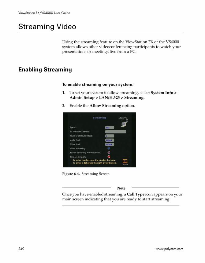
ViewStation FX/VS4000 User Guide
240 www.polycom.com
Streaming Video
Using the streaming feature on the ViewStation FX or the VS4000 system allows other videoconferencing participants to watch your presentations or meetings live from a PC.
Enabling Streaming
To enable streaming on your system:
1. To set your system to allow streaming, select System Info > Admin Setup > LAN/H.323 > Streaming.
2. Enable the Allow Streaming option.
Figure 6-4. Streaming Screen
Note
Once you have enabled streaming, a Call Type icon appears on your main screen indicating that you are ready to start streaming.
Chapter 6 - Using Advanced System Features
© Polycom, Inc. 2003 241
Configuring Streaming Options
You can now configure the following options on the Streaming screen.
❑ Speed—Press the SELECT button on the remote control and select the speed at which you want to stream video.
❑ IP Multicast Address—A default address is entered for you based on your serial number. This ensures that you do not have the same multicast address as another system. You can change this address.
❑ Number of Router Hops—Enter the number of routers you want the streaming video to pass through. This allows you to control who can see your streaming video.
❑ Audio Port—This is a fixed port. This may be changed by your network manager if a user needs to go through the firewall.
❑ Video Port—This is a fixed port. This may be changed by your network manager if a user needs to go through the firewall.
❑ Allow Streaming—When this option is enabled, the icon on the main screen of the user interface changes from Telephone to Call Type. Click Call Type to access the Streaming Call screen. In the Streaming Call screen, you can set a Meeting Password. Click the Start icon to start streaming.
❑ Enable Streaming Announcement—When this option is enabled, the names of users logged on to your system are displayed on screen.
❑ Restore Defaults—Selecting this option restores the Speed, IP Multicast Address, Number of Router Hops, Audio Port, and Video Port defaults.

ViewStation FX/VS4000 User Guide
242 www.polycom.com
Configuring Streaming for Apple QuickTime
Enabling and Starting Streaming on the ViewStation FX or VS4000
To enable streaming on your system:
1. Go to the Streaming screen (System Info > Admin Setup > LAN/H.323 > Streaming).
2. Make sure that Enable Streaming Announcement is enabled. It should be set by default.
3. Enable Allow Streaming.
To start sending a stream:
1. From the main screen, select Call Type.
2. Select Streaming Call. Decide if you need a password.
3. Click Start. A Streaming icon is now displayed on the upper left corner of your television screen.
You can start streaming before or after you place a video call. If you are streaming a presentation, you can go ahead and start the presentation immediately.
Viewing Streaming with Apple QuickTime on the PC
To view the stream with Apple Quick Time on your PC:
1. Make sure you have enabled and started streaming on your ViewStation FX or your VS4000 system as described in “Enabling and Starting Streaming on the ViewStation FX or VS4000.”
2. To view streaming using Apple QuickTime:
a. Open a Web browser.

Chapter 6 - Using Advanced System Features
© Polycom, Inc. 2003 243
b. Enter the IP address of your ViewStation FX or your VS4000 system in the browser address field.
c. Click on the View a Meeting icon.
d. In the View a Meeting screen, click the View Streaming Video icon.
e. Enter your user name and password when prompted.
f. Apple QuickTime will launch within your browser.
Note
If you do not have Apple QuickTime installed, you will be prompted to install it from the Polycom/QuickTime Web page. Repeat steps 1 through 3 after installation.
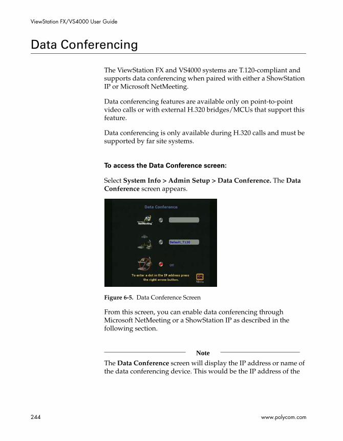
ViewStation FX/VS4000 User Guide
244 www.polycom.com
Data Conferencing
The ViewStation FX and VS4000 systems are T.120-compliant and supports data conferencing when paired with either a ShowStation IP or Microsoft NetMeeting.
Data conferencing features are available only on point-to-point video calls or with external H.320 bridges/MCUs that support this feature.
Data conferencing is only available during H.320 calls and must be supported by far site systems.
To access the Data Conference screen:
Select System Info > Admin Setup > Data Conference. The Data Conference screen appears.
Figure 6-5. Data Conference Screen
From this screen, you can enable data conferencing through Microsoft NetMeeting or a ShowStation IP as described in the following section.
Note
The Data Conference screen will display the IP address or name of the data conferencing device. This would be the IP address of the
Chapter 6 - Using Advanced System Features
© Polycom, Inc. 2003 245
StreamStation, WebStation or ShowStation itself, or, the IP address of the PC on which Netmeeting is running.
Enabling Data Conferencing on your System
The following explains how to enable the data conferencing capabilities on the ViewStation FX or VS4000 system.
To enable data conferencing:
1. Select System Info > Admin Setup > Data Conference. The Data Conference screen appears.
2. Enable either the NetMeeting or ShowStation IP option. The ShowStation IP option appears only if a ShowStation is connected to the ViewStation FX, the VS4000, or the LAN.
Note
Data conferencing is only available during H.320 calls and must be supported by far-site systems
Using a ShowStation IP
For more information on ShowStation IP, see ShowStation IP on page 55.
Using Microsoft NetMeeting
For more information about data conferencing using NetMeeting, refer to NetMeeting on page 273 in chapter 7.

ViewStation FX/VS4000 User Guide
246 www.polycom.com
People+Content
The Polycom People+Content (P+C) standard, implemented on the ViewStation EX, ViewStation FX, VS4000, MGC 5.0, iPower 5.0, and PathNavigator products, allows live video and live graphics to be transmitted and received with all the above-listed Polycom products.
In a multipoint videoconference, all endpoints see the same content video, and the people video can be displayed in either discussion or voice-switched mode, depending on the MCU settings.
If all endpoints (ViewStation EX, ViewStation FX, VS4000, or iPower) to which your system is connected support P+C, then the systems automatically enable this feature. The MGC has to be manually configured prior to the start of a conference to support this new standard.
Compatibility
Radvision Onlan and ECS gatekeepers do not support People+Content in routed mode. The People+Content format is not supported through the Radvision Onlan 2.2 and the Radvision ECS 2.02 gatekeepers if the gatekeeper is set for routed mode. The People+Content format functions in direct mode.
People+Content and PathNavigator compatibility. ViewStation FX and VS4000 systems with version 5.0 can only send the previous version of dual streams to another ViewStation EX, FX, or VS4000 system with version 5.0 when registered with PathNavigator 1.10. ViewStation FX and VS4000 systems 5.0cannot send dual streams to an iPower version 5.0 when registered to PathNavigator version 1.10. ViewStation EX, FX, and VS4000 systems send the new People+Content format to other ViewStation EX, FX, VS4000, or iPower systems if they are registered to PathNavigator 5.0.

© Polycom, Inc. 2003 247
7Using the System with a PC
This chapter describes how to use your ViewStation FX or your VS4000 system in conjunction with a PC.
Topics in This Chapter
The following topics are included in this chapter.
Topic Description Page
Before you Begin
This section explains how to set up and connect your PC to a ViewStation FX or VS4000 system and how to configure your Web browser as a prerequisite to be able to use the system Web interface.
248
Accessing the Web Interface
This section explains how to access your system’s main Web screen.
256
Features of the Web Interface
This section explains how to place a call, load and select a presentation, view a slide presentation, and view a meeting, and use Closed Caption.
257
PC-Resident Applications
This section explains how to access and PolycomSnap, NetMeeting, and the Polycom Management Access Control Wizard.
271
System Setup and Remote Management
This section covers information about the Web interface system setup and remote management tools.
281
Streaming This sections provides instructions about streaming from the Web interface.
289
ViewStation FX/VS4000 User Guide
248 www.polycom.com
Before you Begin
In order to access and use the ViewStation FX or VS4000 Web interface, you need to:
❑ Set up and connect your PC to a ViewStation FX or VS4000 system.
• PC Requirements
• Connecting the PC and the ViewStation FX or the VS4000 to the LAN
• Connecting the PC Directly to a ViewStation FX or a VS4000 not on the LAN
❑ Configure your Web browser to work correctly with the ViewStation FX or VS4000 Web interface. See Configuring your Web Browser.
PC Requirements
❑ You need the following items to connect the PC to the ViewStation FX or VS4000 system:Microsoft Windows 98 or newer
❑ Desktop PC connected to a LAN or laptop with a 10 Mbps or 100 Mbps Ethernet LAN card
❑ Ethernet cable
❑ Microsoft Internet Explorer 5.5 or higher (recommended) or Netscape 6.0 or higher
Connecting the PC and the ViewStation FX or the VS4000 to the LAN
1. To connect the system to the LAN:
a. Insert one end of the provided orange RJ-45 cable into the orange LAN port on the back of the system.

Chapter 7 - Using the System with a PC
© Polycom, Inc. 2003 249
b. Insert the other end of the cable into a port on the LAN. This connection is shown in the QuickStart.
2. To connect the PC to the system:
a. Insert one end of the provided blue RJ-45 cable into the blue PC port on the back of the system.
b. Insert the other end of the cable into the Ethernet port on your computer.
3. Power on the system.
4. Select System Info > Admin Setup > LAN/H.323 > LAN/Intranet to configure the system’s LAN/H.323 settings. The LAN & Intranet screen appears.
Figure 7-1. LAN & Intranet Screen
5. In the LAN & Intranet screen, configure the system DHCP settings, as follows:

ViewStation FX/VS4000 User Guide
250 www.polycom.com
If your LAN uses DHCP:
a. Select Client in the DHCP field to enable your system to obtain an IP address from a server on your network.
b. After you have changed the DHCP settings, a message lets you know that your system will have to be reset in order to save the changes. Select Yes. Another message informs you that your system is about to restart.
c. Select the System Info icon to go to the System Information screen. Your system's IP address should appear in the IP Address field.
Note
If the IP address field displays “...waiting...,” your system did not get an address from a server on your LAN. Check the LAN connection on the back of your system and try again. When your system is properly connected, the green light on the connector is illuminated and the orange light is blinking.
If your LAN does not use DHCP:
a. Select Off in the DHCP field and manually enter the IP address, subnet mask, and gateway address provided by your system administrator.
b. On the PC side: Once your PC is connected to the your system, make sure it is properly configured. This can be a rather complex process that should be best handled by your network administrator.
c. After you have changed the DHCP settings, a message lets you know that your system will have to be reset in order to save the changes. Select Yes. Another message informs you that your system is about to restart. For instructions about how to access your system’s Web interface, proceed to Accessing the Web Interface on page 256.

Chapter 7 - Using the System with a PC
© Polycom, Inc. 2003 251
Connecting the PC Directly to a ViewStation FX or a VS4000 not on the LAN
Complete the following steps to connect your PC to a ViewStation FX or a VS4000 system that is not on the LAN:
1. To connect your PC to your system:
a. Insert one end of the provided blue RJ-45 cable into the blue PC port on the back of your system.
b. Insert the other end of the cable into the Ethernet port on your computer.
2. Power on your system.
3. To connect to your desktop or laptop computer, you need to set your system as a DHCP server. This assumes that the option Allow System to be a DHCP Server was enabled during software upgrade of your system. Enable DHCP Server as follows:
a. Select System Info > Admin Setup > LAN/H.323 > LAN/Intranet on the user interface.
b. Press the up arrow on the remote control to go to the DHCP field and set it to Server. The following message will appear: “The system will now issue IP addresses to other PCs on the LAN. Continue?”
Caution
Do not use this setting if your system is on a LAN with other computers. If you do, it will provide IP addresses to the other computers even though the LAN already has a DHCP server. Your IT personnel and system administrators will have to repair any network problems this causes.
c. Select Yes if you are absolutely certain you want to set your system as a DHCP server.
d. Press Menu. The following message will appear: “Power must be reset to save changes. Continue?” Select Yes.
ViewStation FX/VS4000 User Guide
252 www.polycom.com
e. Your system will automatically restart. It will now act as a DHCP server and will provide IP addresses to one or more PCs.
4. Go to the System Information screen. You should see an IP address of 1.1.1.2, which is the IP address of your system.
5. Once you get an IP address, go to your PC and follow these instructions:
For Windows 98:
a. Right-click the Network Neighborhood icon, and then right-click Properties.
b. When the Network box appears, select the Configuration tab, then double-click TCP/IP.
c. Select the IP Address tab. Make sure the Obtain an IP Address Automatically button is selected. Then click OK.
For Windows NT 4.0:
a. Right-click the Network Neighborhood icon, and then right-click Properties.
b. When the Network screen appears, select the Protocols tab, then double-click TCP/IP Protocol.
c. Select the IP Address tab. Make sure the Obtain an IP Address Automatically button is selected. Then click OK.
For Windows 2000:
a. Right-click the My Network Places icon, and then right-click Properties.
b. In the Network and Dial-up Connections window, right-click Local Area Connection, and select Properties.
c. In the Local Area Connection Properties window, double-click Internet Protocol (TCP/IP).

Chapter 7 - Using the System with a PC
© Polycom, Inc. 2003 253
d. In the Internet Protocol (TCP/IP) Properties window, make sure the Obtain an IP Address Automatically button is selected. Then click OK.
6. Restart your PC. For instructions about how to access your system’s Web interface, proceed to the next section.
Configuring your Web Browser
In order for the ViewStation FX or VS4000 Web interface to work properly, you must configure your Web browser (Internet Explorer or Netscape) as described in this section.
Internet Explorer Configuration
Correct configuration of Internet Explorer requires that you allow cookies and force pages to be reloaded every time. The following instructions are for Internet Explorer 5.5 and higher.
To force pages to be reloaded:
1. Launch Internet Explorer
2. Select Tools from the menu.
3. Select Internet Options.
4. Select the General tab, and under Temporary Internet files, click Settings.
5. Under check for newer versions of stored pages, select every visit to the page.
6. Click OK twice.
To allow cookies:
1. Launch Internet Explorer
2. Select Tools from the menu.
3. Select Internet Options.
ViewStation FX/VS4000 User Guide
254 www.polycom.com
4. Select the Privacy tab, and under Settings, move the slider to the medium high setting (or a lower setting).
5. Click OK.
Netscape Configuration
Correct configuration of Netscape requires that you enable JavaScript, allow cookies, and set the cache. The following instructions are for Netscape 6.0 and higher.
To enable JavaScript:
1. Launch your Web browser.
2. Select Edit fromthe menu.
3. Under the Advanced category, click Enable JavaScript.
To allow cookies:
1. Launch your Web browser.
2. Select Edit from the menu.
3. In the Advanced tab, under Cookies, enable one of the two following options:
• Accept all cookies.
• Accept all cookies that get sent back to the originating server.
Note
For Netscape 6.x, the Cookies area is to be found in the Privacy and Security tab.
4. Click OK.

Chapter 7 - Using the System with a PC
© Polycom, Inc. 2003 255
To set the cache:
1. Launch your Web browser.
2. Select Edit from the menu.
3. In the Advanced category, under Cache, select Compare the page in the Cache to the page on the network every time.
ViewStation FX/VS4000 User Guide
256 www.polycom.com
Accessing the Web Interface
This section assumes that your PC is already connected to your ViewStation system either directly or over the LAN and that you have configured your Web browser, as described in the previous section.
To access the Web interface:
1. Launch Microsoft Internet Explorer on your PC.
2. Enter the IP address of your system on the address line of your browser. (Your system’s IP address is displayed on the System Information screen.)
The system’s Web interface main page appears on your Internet browser displaying the name of your sytem.
The main icons are displayed on the left panel of the Web page: Place a Call, Set Up System, Select a Presentation, View a Presentation, Show Closed Caption, and Configure NetMeeting.
Note
The Streaming icon is only visible when streaming is already enabled. Refer to Streaming for more information.
3. Select Internet Options from the Tools menu of the browser and make sure that security is set to Medium on the Security tab. Click OK.
Note
Web Interface Resolution Display: The system’s Web interface does not support the 800x600 resolution.

Chapter 7 - Using the System with a PC
© Polycom, Inc. 2003 257
Features of the Web Interface
This section explains how to use the following Web interface features:
❑ Placing a Call
❑ Loading and Selecting a Slide Presentation
❑ Viewing a Slide Presentation
❑ Viewing a Meeting
❑ Closed Caption
Placing a Call
The Web interface can be used to place remote calls from a ViewStation FX or a VS4000 system.You can place a call in one of three different ways:
From the Address Book. See Placing a Call from the Address Book.
From the Global Address Book. See Placing a Call from the Global Address Book.
Using the Manual Dialer. See Placing a Call Using the Manual Dialer.
To access the Placing a Video Call screen:
Click the Place a Call icon in the left panel of the main Web screen.

ViewStation FX/VS4000 User Guide
258 www.polycom.com
Figure 7-2 shows the main Web dialing page (Placing a Video Call).
Figure 7-2. Placing a Video Call Web Screen
The Global Address Book call option is only available if a server IP address has been entered in the Global Address screen on your system and the option Display Global Addresses is enabled (System Info > Admin Setup > LAN/H.323 > Global Address > Server).
If the option Allow Remote Monitoring is enabled on your system (System Info > User Setup), you can watch the call go through at the bottom of the page where call status information and streaming video snapshots from the call are displayed.
Several icons are displayed at the top and in the left panel on the Web page. The icons in the left panel allow you to access statistical tools, the virtual remote control, and streaming. The icons at the top of the Web page give you quick access to all the Admin Setup and Diagnostics screens, as well as to the most-often used features, such as View a Presentation, Slide Presentation, and Place a Call.

Chapter 7 - Using the System with a PC
© Polycom, Inc. 2003 259
Placing a Call from the Address Book
To place a call from the Address Book:
1. From the Web interface main page, select Place a Call. The Placing a Video Call page appears.
2. Select the Address Book tab.
3. Select the site from the list.
4. Click the Call this Site button.
Placing a Call from the Global Address Book
To place a call from the Global Address Book:
1. From the Web interface main page, select Place a Call. The Placing a Video Call page appears.
2. Select the Global Address Book tab.
3. Select the name to dial from the list on the left.
4. Click Call this Site.
Placing a Call Using the Manual Dialer
To place a call using the Manual Dialer:
1. From the Web interface main page, select Place a Call. The Placing a Video Call page appears.
2. Select the Manual Dial tab.
3. Enter the video numbers or extension. If this is not a bonded call (2 x 56 or 2 x 64 Kbps) with two different video numbers, enter the first video number in the Video A field, and the second one in the Video B field. If the video number is the same for both channels, then enter it in the Video A field. Otherwise, enter the number in the Video A field and leave the Video B field blank.

ViewStation FX/VS4000 User Guide
260 www.polycom.com
4. Select the line speed.
5. Select the call type (ISDN, IP, or AUTO).
Note
Note that if Auto H.323 Dialing is enabled on the system (Admin Setup > LAN/H.323 > H.323 > Setup), the system will be able to auto-detect the type of call you are placing (IP or ISDN) based on the video number format. Consequently, the ISDN and H.323 fields on this Web page are not visible.Auto H.323 Dialing is enabled by default.
6. Click the Call button.
To terminate your call:
Click the Hang Up button.
Loading and Selecting a Slide Presentation
The following explains how to load a slide presentation from the PC to the ViewStation system using the Web interface and present those slides in a video call.
The following lists key information about loading a presentation:
❑ The system is only compatible with Microsoft PowerPoint 97 or higher.
❑ Because the system does not have a hard drive, the computer that is used to upload the presentation must be left on during the presentation and the pcPresent application window must be active.
❑ You can load up to eight presentations on a system. Each presentation must originate on a separate PC.
❑ The PC from which you are presenting cannot be running an FTP service.

Chapter 7 - Using the System with a PC
© Polycom, Inc. 2003 261
Loading a Slide Presentation on the PC
To load a slide presentation on the ViewStation system:
1. Launch Internet Explorer 5.5 or higher.
Note
Make sure your browser is configured to accept cookies.
2. Enter the IP address or the LAN host name of the system on which you want to display the slides.
Example:
IP address: http://192.168.1.102
LAN host name: http://Main_System
3. In the main Web page, click the Select a Presentation icon. The Select a Presentation for Viewing Web page appears.
Note
For added security, you can specify a password for a presentation started from a PC. Users must enter the specified password in order to load the presentation. If you wish to view the presentation, you must enter the meeting password.

ViewStation FX/VS4000 User Guide
262 www.polycom.com
4. Click the Press Here to Select a PowerPoint Presentation button. The pcPresent dialog box appears.
Figure 7-3. pcPresent Screen
5. In the pcPresent screen, configure the following options:
a. Enter your name (your host name is here by default).
b. Enter a password...: Enter a presentation password, if you wish to establish one for the presentation. You will be prompted later for this password when you select the presentation.
c. Use NAT Address: Enable or disable the Use NAT Address option as is appropriate as described below. Use NAT Address is enabled by default. The Use NAT Address field only appears if the system detects a NAT device.
– If your PC or laptop is behind a NAT device but the system is not, make sure that Use NAT Address is enabled. In addition, you will have to open the following ports in the NAT device so that the slides can successfully load into the system:
80 (http port)
21 (ftp control port)
5004 and 65000 ports
– If your PC or laptop and the system are both behind the same NAT device, disable the option Use NAT Address.

Chapter 7 - Using the System with a PC
© Polycom, Inc. 2003 263
Note
If the security level on your Internet browser is set too high, you will not be able to bypass the password. If this occurs, change the security level to low or medium.
6. Click the Please press here to select a PowerPoint presentation button. The File Open dialog box appears.
Figure 7-4. pcPresent: File Open Screen
7. On your PC, navigate to the presentation file and select it.
8. Click the pcPresent button. A window appears indicating that your slides are being converted to thumbnail sketches. Once this is complete, your thumbnails are loaded into the flash memory of the system.
Selecting a Slide Presentation on the ViewStation FX or VS4000
Complete the following steps on your system to select the presentation:
1. Press the SLIDES button on the remote control. The Available Presentations screen appears on the monitor attached to the system:
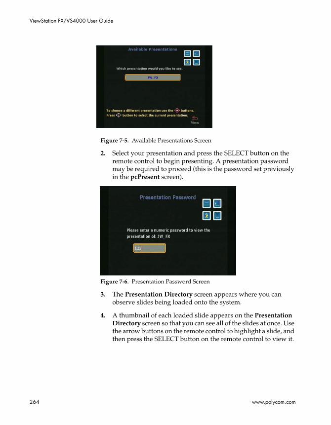
ViewStation FX/VS4000 User Guide
264 www.polycom.com
Figure 7-5. Available Presentations Screen
2. Select your presentation and press the SELECT button on the remote control to begin presenting. A presentation password may be required to proceed (this is the password set previously in the pcPresent screen).
Figure 7-6. Presentation Password Screen
3. The Presentation Directory screen appears where you can observe slides being loaded onto the system.
4. A thumbnail of each loaded slide appears on the Presentation Directory screen so that you can see all of the slides at once. Use the arrow buttons on the remote control to highlight a slide, and then press the SELECT button on the remote control to view it.

Chapter 7 - Using the System with a PC
© Polycom, Inc. 2003 265
Figure 7-7. Presentation Directory (showing Loaded Slides) Screen
5. To get information about the slide you are viewing, press the INFO button on the remote control. The names of the presenter and the presentation appear, as well as the slide number, and the viewing password. The viewing password is set in the Security screen as the Meeting Password field (System Info > Admin Setup > Security). You can change the password on a presentation while you are viewing it by highlighting the Viewing Password field on the Slide Presentation Information screen and entering a new password.
6. Use the remote control to move through a presentation, as follows:
• To move backward and forward through your presentation, use the LEFT and RIGHT ARROW buttons.
• To go to the beginning of the presentation, press the UP ARROW button.
• To go to the end, press the DOWN ARROW button.
• If you want to go from viewing a slide to viewing its thumbnail, press the MENU button on the remote control. Press the SELECT button on the remote control to return to live video. If you press the SLIDES button, you can select another presentation.

ViewStation FX/VS4000 User Guide
266 www.polycom.com
Slide Display Information
1. High-Resolution Slides. The ViewStation FX or VS4000 system is capable of displaying high-resolution graphics on an attached monitor. For more information, refer to Monitors on page 333.
Slide Presentation Function and Annex D Support. A graphics slide or snapshot sent from one videoconferencing system to another system may not be displayed properly if the receiving system does not support the Annex D high-resolution graphics standard.
Polycom supports this graphics standard. However, if a Polycom system sends a slide or snapshot to another vendor’s system that does not support Annex D, the graphic appears on the far site monitor for a few seconds and then disappears. If this problem is encountered, verify that the other side’s system supports the Annex D high-resolution standard.
Note
All Polycom videoconferencing products, including the ViaVideo desktop system, support the Annex D high-resolution graphics standard.
Viewing a Slide Presentation
You can view slides (that are being presented with a ViewStation system) on your PC using the ViewStation FX or VS4000 Web interface.
A maximum of 30 parties can simultaneously view the presentation for each ViewStation FX or VS4000 system in a call. For example, in a call with another system (2 systems), 60 parties can view your presentation on 60 separate PCs (2 systems x 30 parties).
Note
A user cannot view a slide presentation and select a slide presentation from the same PC.

Chapter 7 - Using the System with a PC
© Polycom, Inc. 2003 267
To view slides that are being presented:
1. Launch Internet Explorer 5.5 or higher, or Netscape 6.0 or higher.
2. Enter the IP address of one of the ViewStation FX or VS4000 systems participating in the videoconference. The Web interface main page appears.
3. Click the View a Presentation icon. The Enter Network Password dialog box appears.
4. Enter your name and a password, if one is required. The password is the Meeting Password, which is set in the Security screen (System Info > Admin Setup > Security) of the system, or in the User Setup screen (System Info > User Setup).
5. Click OK. The slides appear.

ViewStation FX/VS4000 User Guide
268 www.polycom.com
Viewing a Meeting
If streaming is enabled on your ViewStation FX or VS4000 system, the Web View a Presentation icon is replaced by the View a Meeting icon., the Web View a Presentation icon is replaced by the View a Meeting icon. For more information about streaming, refer to the section Streaming, on page 289.
When you select View a Meeting, two options are available: View a Slide Presentation and View Streaming Video.
Figure 7-8. View a Meeting Web Screen
To view a streamed slide presentation:
Click View a Slide Presentation.
To view streamed video:
Click View Streaming Video.
Closed Caption
Closed Caption is a Polycom-proprietary software feature that lets you display text on the main video screen of the local and far ViewStation FX or the VS4000 systems.This is done using the system’s Web interface.

Chapter 7 - Using the System with a PC
© Polycom, Inc. 2003 269
Closed Caption is particularly well suited for people participating in video communications who can only communicate through written messages or who need to have the verbal exchange of other participants transcribed or translated on the fly for them. Closed caption is also a useful tool for the hearing impaired or foreign speakers.
Accessing and Using Closed Caption
To access Closed Caption:
1. Start Internet Explorer 5.5 or higher or Netscape 6.0 or higher.
2. Place a call to the far site.
3. To launch your system’s Web interface, enter your system’s IP address in the Address field of your Web browser.
4. On the main page of your system’s Web interface, select Show Closed Caption.
5. The Enter Network Password dialog box appears. Enter your name and a password, if one is required. The password is the Meeting Password, which is set in the Security screen (System Info > Admin Setup > Security) of the system, or in the User Setup screen (System Info > User Setup).
6. You are now in the Closed Captioning screen.
To use Closed Caption:
1. Enter your text in the Current field. You can enter up to 250 characters per line at a time.
2. Press the Enter key on your PC keyboard to display your text in the History field. This action will also send and display your text to the near-site and the far-site system. The message is only displayed for 15 seconds.
Additional Information About Closed Caption
❑ Closed Caption works in a call and out of a call.
ViewStation FX/VS4000 User Guide
270 www.polycom.com
❑ Closed Caption works in IP (H.323) and ISDN (H.320) calls.
❑ Closed Caption is only supported when the call occurs between two Polycom ViewStation SP, MP, V.35/RS-449/RS-530, or 512 systems running version 6.5 or greater, and FX or VS4000 systems running software version 2.5 or greater.
❑ Closed Caption is not supported in multipoint calls.
❑ The Closed Caption feature requires that you enter your name (and Meeting Password if you have one) after a call is started or after a call is hung up. You might have to refresh your browser if you hang up the call and you use Closed Caption out of a call.

Chapter 7 - Using the System with a PC
© Polycom, Inc. 2003 271
PC-Resident Applications
This section explains how to use the following advanced Web interface features:
❑ PolycomSnap
❑ NetMeeting
❑ Polycom Management Access Control Wizard (PMAC)
PolycomSnap
PolycomSnap is a PC-resident application that lets you capture JPEG images of the entire PC screen or specific windows or areas of the PC screen and display the snapshots on one or more Polycom ViewStation FX or VS4000 systems. PolycomSnap can be used in a multipoint videoconference to display snapshots of your PC to all of the participating systems simultaneously.
To download and use PolycomSnap:
1. Click PolycomSnap on the Web interface main page.
2. A File Download window appears. Choose one of the options (Run this program from its current location or Save it to disk) and click OK.

ViewStation FX/VS4000 User Guide
272 www.polycom.com
3. Follow the on-screen instructions to download the application. When you launch the PolycomSnap application, the following interface is displayed:
Figure 7-9. PolycomSnap Interface
4. Click the Connect tab of the PolycomSnap interface. Enter the IP address of the system in the Address field. This is the IP address of the system to which the snapshots are to be sent.
A password may be required. The password is the Meeting Password which is set in the Security screen (System Info > Admin Setup > Security) of the system, or in the User Setup screen (System Info > User Setup).
5. Click the Connect button. Your system is now ready to receive snapshots.
6. Click the Area tab. Select the snapshot area you want to capture.
7. Click the Snapshot tab. Select the snapshot capture mode.
8. Then press the PolycomSnap Snap button, or press F9 on your PC keyboard to send a snapshot of your PC desktop to the system connected to your system.
9. To disconnect, click the Disconnect button under the Connect tab.

Chapter 7 - Using the System with a PC
© Polycom, Inc. 2003 273
NetMeeting
You can place data calls through Microsoft NetMeeting. NetMeeting data is transmitted via the network and is displayed on the PC at each site. Data conferencing is only available during ISDN (H.320) calls and must be supported by far-site systems.
Note
For more information about data conferencing, refer to Data Conference on page 330. This section also contains information about how to use a ShowStation IP.
The following lists key information about data conferencing using NetMeeting:
❑ To use the NetMeeting application sharing, file transfer, and whiteboarding, your PC must be connected to your system via your LAN.
❑ NetMeeting data is transmitted via the H.320 network. The bandwidth used is dynamically allocated so that when NetMeeting is not sending data, the bandwidth used returns to the video data.
❑ System Compatibility and NetMeeting 3.0. T.120 application sharing, file transfer, and whiteboarding are supported for NetMeeting 3.0 when used with two systems. You must have the same version of NetMeeting installed on both ends of the conference. These functions are not supported for NetMeeting 3.0 when used with a ViewStation FX or VS4000 system and a videoconferencing unit from another vendor. In these situations, you must install NetMeeting 2.11.
❑ Security Restrictions. For security reasons, the firewall will not allow application sharing, file transfer, and whiteboarding in an IP (H.323) call (on your system). Use NetMeeting to perform these functions between two PCs once a connection to the far site has been established.
❑ During the NetMeeting call, the whiteboard, chat, application sharing, and file-transfer capabilities are available. Audio and video are provided via the system.
ViewStation FX/VS4000 User Guide
274 www.polycom.com
❑ If additional participants want to join a NetMeeting conference, they can place a NetMeeting call to the IP address of either PC in the call.
Enabling NetMeeting on the ViewStation FX or VS4000
The following describes how to enable your system’s data conferencing capabilities.
To enable NetMeeting on your system:
1. Select System Info > Admin Setup > Data Conference. The Data Conference screen appears.
2. Enable either the NetMeeting or the T.120 device option. The ShowStation IP option appears only if a ShowStation IP is connected to your system or the LAN.
Accessing NetMeeting
To access NetMeeting:
1. Place a point-to-point ISDN (H.320) call to the remote site. Make sure the remote site has also placed a call to the local site.
2. Open Internet Explorer 5.5 or higher or Netscape 6.0 or higher on your PC and enter the IP address of your system in the Address field of your browser. your system’s Web interface main page appears on your PC.
3. Click the Configure NetMeeting icon.
If an admin password is required, the Enter Network Password window appears. The following information is needed:
a. Enter your name in the User Name field (use “admin” as the user name).
b. Enter the admin password in the Password field. This password is set in the Security screen (System Info > Admin Setup > Security) of your system.

Chapter 7 - Using the System with a PC
© Polycom, Inc. 2003 275
c. Click OK.
4. You are now in the How to Start a NetMeeting Call Web screen. You can either follow the on-screen instructions or proceed with the present instructions.
5. Enter the IP address of your PC.
Note
In Windows 98 and ME, you can find your PC’s IP address by clicking the Start button on your PC desktop. Then, click Run, and type winipcfg in the Open box. In Windows NT and 2000, you can get your IP address by typing ipconfig at the command prompt.You can also obtain the IP address of your PC from the NetMeeting application. Click Help and About NetMeeting.
6. To open NetMeeting on your PC, double-click the NetMeeting Application icon. Make sure the far site has also launched NetMeeting.
7. Select Call > New Call from the NetMeeting menu on the PC connected to the system that initiated the videoconference. Or you can also click the phone icon on the right of the menu. The Place a Call window opens.
8. In the To field, enter the IP address of the system that is connected to your PC. For easy reference, the IP address of the system is provided on the How to Start a NetMeeting Call Web page.
Information About Placing an IP Video Calls with NetMeeting
You can make IP (H.323) video calls to and from a PC using NetMeeting 2.11 or 3.0.
Line Speed. The line speed of a video call from NetMeeting to a ViewStation FX or VS4000 system depends on the bandwidth setting in NetMeeting:
❑ Cable, xDSL, or ISDN = 128 Kbps
❑ Local Area Network = 384 Kbps
ViewStation FX/VS4000 User Guide
276 www.polycom.com
Calls from a ViewStation FX or VS4000 system to NetMeeting must be at line speeds higher than 64 Kbps.
Restrictions. You cannot use application sharing with NetMeeting while in an IP (H.323) call with a ViewStation FX or VS4000 system.
Compatibility. NetMeeting 3.0 is compatible with ViewStation FX or VS4000 systems version 3.0 or higher for H.323 video calls. For these calls, you must disable the following two security options on the Security tab (NetMeeting Tools > Options):
❑ I prefer to receive secure incoming calls
❑ I prefer to make secure outgoing calls
Polycom Management Access Control Wizard (PMAC)
This stand-alone application allows administrators to easily add Help desk numbers, company logos, and a new high-level management password that would be needed to access any or all user interface screens that the user chooses to protect.
This application is available on your software CD and can also be downloaded from the Polycom Website ( Go to http://www.polycom.com/resource_center/. Then select Software Downloads.)
All these PMAC features can be loaded to any ViewStationFX or VS4000 systems on a per-unit basis.
❑ From the PMAC utility, the administrator can:
❑ Install system logos
❑ Create custom speed dial screen
❑ Create management password
❑ Password-protect individual screens
❑ Connect/disconnect to and from a system
❑ Open and save profiles
Chapter 7 - Using the System with a PC
© Polycom, Inc. 2003 277
Installing a Logo
You can add your own logo to the main menu through the PMAC utility screen. The logo will appear in the top right corner of the screen.
Note
Note: The logo must be a jpg image and smaller than 125 x 75 pixels.
To add your own logo:
1. Launch the PMAC utility.
2. Enter the IP Address and the Password of your system.
3. Click the System Logo tab.
4. Click the Browse button to navigate to the jpg file you wish to install.
5. Clicking the OK button will apply the changes, however it will close the application.
6. Click the Apply button to install the logo.
Creating Custom Speed Dial and Custom Video Numbers Screens
The normal Speed Dial screen contains the six most-recent calls. In the Custom Speed Dial screen, you can create additional Speed Dial buttons. The custom Speed Dial screen can only be created, edited, and deleted from the PMAC utility.
To access the Custom Speed Dial and Custom Video Numbers
screens:
1. First, install a custom Logo on the system (see preceding section).
2. Select the appropriate custom Logo. Selecting a custom Logo takes you automatically to the custom Speed Dial screen.

ViewStation FX/VS4000 User Guide
278 www.polycom.com
To install Custom Video Numbers:
1. Launch the PMAC utility.
2. Enter the IP address and the Password of the system.
3. Click the Custom Video Numbers tab.
4. Enter a Screen Title.
5. Enter a Site Name.
6. Enter the Site Number.
7. From the drop-down menu, select a Call Speed.
8. From the drop-down menu, select a Call Type (IP or ISDN).
9. Select the Apply button to install the settings.
Note
To erase all settings, select the Clear All button.
Creating the Management Password
The Management Password is different from the Admin Password. The Admin Password allows access to the Admin Setup screens. The Management Password allows the administrator to password-protect (lock) specific screens. In other words, the Admin Password allows a user to access the admin section, but the Management Password is needed to access a specific screen.
To create a Management Password:
1. Launch the PMAC utility.
2. Enter the IP address and the Password of the system.
3. Select the Management Password tab.
4. Enter the Management Password. Re-enter the Management Password.

Chapter 7 - Using the System with a PC
© Polycom, Inc. 2003 279
5. Clisk the Apply button to install the settings.
When you try to access a screen that is password protected, you are prompted to enter the Management Password. If the wrong password is entered, you are not allowed to access the screen.
The Management Password overrides the Admin Password. For example, if you have both an Admin Password and a Management Password, use the Management Password to log into the system from the PMAC utility.
Password-Protecting Individual Screens
In order to password-protect screens, a Management Password must be created first (see preceding section). Then, from the Screen Access tab, you can specify which screens to lock.
To password-protect (lock) an individual screen:
1. Launch the PMAC utility.
2. Enter the IP Address and Password of your system.
3. Select the Screen Access tab.
4. Double- click an item in the left column (Select Screens from). While holding the Ctrl key on the keyboard, single-click as many items in that column.
5. Press the --> button to move items from the left to the right column. Items in the right column (Do not Allow Access to Screens) are password-protected screens.
Table 7-1. Password Usage with PMAC
Admin PasswordManagement Password
Password to Use When Using PMAC
Yes No Admin
Yes Yes Management
No Yes Management
No No No password

ViewStation FX/VS4000 User Guide
280 www.polycom.com
6. Select the Apply button to install the settings.
To remove password-protected screens:
1. Double-click an item in the right column of the Screen Access screen. While holding the Ctrl key on the keyboard, single-click as many items in that column.
2. Press the <-- button to move items from the right to the left column.
3. Select the Apply button to install the settings.
Connecting to and Disconnecting from your System
After you have updated your system using the PMAC utility, click Disconnect.
When the PMAC utility is not connected to a system, the Connect button appears at the top.
Open and Save Profiles
This Open/Save option can save Custom Video Numbers, the Management Password, the password-protected screens, and the system Logo settings. You can then log into another video system and upload the Profile.
To save or open a Profile:
1. Click Profile from the utility’s menu.
2. Click Open to open a previously saved profile.
3. Click Save to save all the settings.

Chapter 7 - Using the System with a PC
© Polycom, Inc. 2003 281
System Setup and Remote Management
The ViewStation FX or VS4000 system’s Web interface lets you perform most of the setup, configuration, and diagnostics tasks that are available on the ViewStation FX or VS4000 system’s user interface. These tools are grouped under two icons:
❑ Admin Setup—Most of the setup, configuration, and message screens can be accessed from this icon. See Admin Setup/General Setup on page 282.
❑ Diagnostics—Most of the diagnostic screens and tools can be accessed from this icon. See System Diagnostics on page 283.
To access screens grouped under the Admin Setup and
Diagnostics icons:
1. Launch your Web browser and enter the IP address of the system you want to manage in the Web browser’s Address field. The system’s Web interface main page appears.
Note
Internet Explorer 5.5 or higher is recommended over Netscape Navigator because the ViewStation FX or VS4000 system uses Microsoft’s ActiveX controls to enable the PowerPoint presentation capability.
2. Click the Set Up System icon. The System Information Web screen appears. This screen displays information about your system, as well as the main management and features icons.
Note
You will be prompted to enter an Admin Password if one has been set in the Security screen (System Info > Admin Setup > Security). The user name is “admin.”
3. Select the appropriate icons to go to the corresponding management screens. The icons are organized as follows:

ViewStation FX/VS4000 User Guide
282 www.polycom.com
• Left panel on the Web page (vertically aligned icons):
The Admin Setup and Diagnostics icons allow you to access most of the same setup, configuration, and diagnostic tools that are available on your system. Home is a shortcut back to the main Web page.
• Top of the Web page (horizontally aligned icons):
These icons give you quick access to all the Set Up System and Diagnostics screens, as well as to the most-often used features, such as View a Presentation, Slide Presentation, and Place a Call. These icons are available from any of the screens from anywhere within the Admin Setup environment.
Admin Setup/General Setup
The following information describes how to access the General Setup screen, from where most of the setup and configuration tools are available.
1. To access the General Setup screen (shown below), select Admin Setup from the left or top icon field of the Web screen.
Figure 7-10. General Setup Web Screen

Chapter 7 - Using the System with a PC
© Polycom, Inc. 2003 283
2. Click the icon of the feature you want to change. This screen contains the same setup and configuration tools that are available in your system’s user interface.
3. Click the Update button to update the system with the new settings.
4. Some options require a reboot of the system. If this is the case, the system will reboot automatically.
Note
The Allow User Setup option found on the General Setup screen (of the user interface) is used to enable or disable the User Setup icon on the System Info screen of the user interface. Administrators can use this option to prevent users from changing the user setup functions.
System Diagnostics
This section provides information about the main Diagnostics screen (see System Diagnostics), and the following tools accessible from the System Diagnostics screen:
❑ Virtual Remote Control
❑ Send a Message
❑ Call Detail Report (CDR)
System Diagnostics
The System Diagnostics Web screen contains the same diagnostic tests that you can perform from the ViewStation FX or VS4000 system. The tests that you perform are in real time.
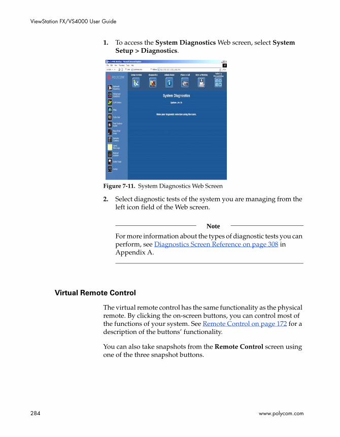
ViewStation FX/VS4000 User Guide
284 www.polycom.com
1. To access the System Diagnostics Web screen, select System Setup > Diagnostics.
Figure 7-11. System Diagnostics Web Screen
2. Select diagnostic tests of the system you are managing from the left icon field of the Web screen.
Note
For more information about the types of diagnostic tests you can perform, see Diagnostics Screen Reference on page 308 in Appendix A.
Virtual Remote Control
The virtual remote control has the same functionality as the physical remote. By clicking the on-screen buttons, you can control most of the functions of your system. See Remote Control on page 172 for a description of the buttons’ functionality.
You can also take snapshots from the Remote Control screen using one of the three snapshot buttons.

Chapter 7 - Using the System with a PC
© Polycom, Inc. 2003 285
To access and use the virtual remote control:
From the System Diagnostics Web screen, click the Remote Control icon to use the Web interface remote control.
Note
To use the virtual remote control, you must use Internet Explorer 4.0 or higher as your Web browser.
To use the snapshot feature:
Click the appropriate button to select your source (Snapshot from Camera 1, Snapshot from Camera 2, or Snapshot from VCR).
The Start Streaming Snapshots feature lets you stream snapshots of the room where the system is located at regular intervals. Each snapshot is displayed for a few seconds. You can set the display time in the Snap Interval field.
Send a Message
This utility lets you send a message to the system that you are managing. Only the near site can see your message.
To send a message using the web interface:
1. From the System Diagnostics Web screen, click the Send Message icon to send a message to a ViewStation FX or VS4000 system.. The text message can be up to 100 characters in length.
2. When the Send a Message Web page appears, type in your message and click the Send Message button. Your message appears on screen for 15 seconds on the system that you are managing.

ViewStation FX/VS4000 User Guide
286 www.polycom.com
Call Detail Report (CDR)
Call Detail Report enables billing and tracking of calls via the Global Management System. It provides the ability to retrieve or delete saved records from the system, and also the ability to properly track IP and multipoint calls.
Call Detail Report can be accessed through your system’s Web interface by selecting Set Up System > Diagnostics > Call Log.
Figure 7-12. Web Interface Call Detail Report screen (partial view)
The columns are displayed in the following order:
1. Row ID—This is a number that indicates the actual order in which call events occurred. The first record in the CDR has a Row ID of 1. Subsequent Row IDs are incremented by 1. This provides a sequentially numbered list of events as they occurred in the CDR. Row ID is also helpful as a line reference number if you need to comment on a specific call while viewing the csv file. Row IDs continue to be incremented in this manner until the maximum CDR file size of 100 K has been reached. At this point, the CDR is archived, and a new CDR file is created. Row ID is then reset to 1 and the process begins again.
2. Start Time—This is the call start time. The time is displayed in the 24-hour format of HH:mm:ss (for example: 18:09:45).
3. End Time—This is the call end time. The time is displayed in the 24-hour format of HH:mm:ss (for example: 18:09:45).
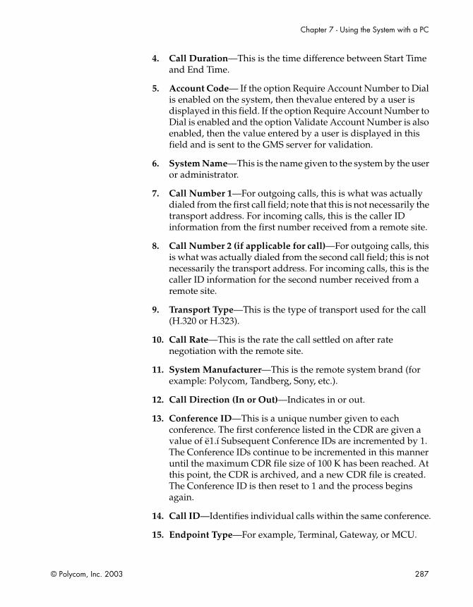
Chapter 7 - Using the System with a PC
© Polycom, Inc. 2003 287
4. Call Duration—This is the time difference between Start Time and End Time.
5. Account Code— If the option Require Account Number to Dial is enabled on the system, then thevalue entered by a user is displayed in this field. If the option Require Account Number to Dial is enabled and the option Validate Account Number is also enabled, then the value entered by a user is displayed in this field and is sent to the GMS server for validation.
6. System Name—This is the name given to the system by the user or administrator.
7. Call Number 1—For outgoing calls, this is what was actually dialed from the first call field; note that this is not necessarily the transport address. For incoming calls, this is the caller ID information from the first number received from a remote site.
8. Call Number 2 (if applicable for call)—For outgoing calls, this is what was actually dialed from the second call field; this is not necessarily the transport address. For incoming calls, this is the caller ID information for the second number received from a remote site.
9. Transport Type—This is the type of transport used for the call (H.320 or H.323).
10. Call Rate—This is the rate the call settled on after rate negotiation with the remote site.
11. System Manufacturer—This is the remote system brand (for example: Polycom, Tandberg, Sony, etc.).
12. Call Direction (In or Out)—Indicates in or out.
13. Conference ID—This is a unique number given to each conference. The first conference listed in the CDR are given a value of ë1.í Subsequent Conference IDs are incremented by 1. The Conference IDs continue to be incremented in this manner until the maximum CDR file size of 100 K has been reached. At this point, the CDR is archived, and a new CDR file is created. The Conference ID is then reset to 1 and the process begins again.
14. Call ID—Identifies individual calls within the same conference.
15. Endpoint Type—For example, Terminal, Gateway, or MCU.

ViewStation FX/VS4000 User Guide
288 www.polycom.com
16. Audio Protocol (Tx)—This is the audio protocol settled on after call negotiation with the remote site (for example: G.728, G.722, etc.).
17. Audio Protocol (Rx)—This is the audio protocol settled on after call negotiation that the far end is sending.
18. Video Protocol (Tx)—This is the video protocol settled on after call negotiation with the remote site (for example: H.261, H.263, etc.).
19. Video Protocol (Rx)—This is the video protocol that the far end is sending.
20. Video Format (Tx)—This is the video format settled on after call negotiation with the remote site (for example: CIF, QCIF, etc.).
21. Video Format (Rx)—This is the video format settled on after call negotiation that the remote site is sending (for example: CIF, QCIF, etc.).
22. Disconnect Reason—This is the Q.850 cause code description associated with the Q.850 numerical cause code.
23. Cause Code—This is the Q.850 numerical cause code that occurs in an H.320/H.323 call after a connection failure or call termination. Note: Reference Q.850 documentation for cause code number and description.
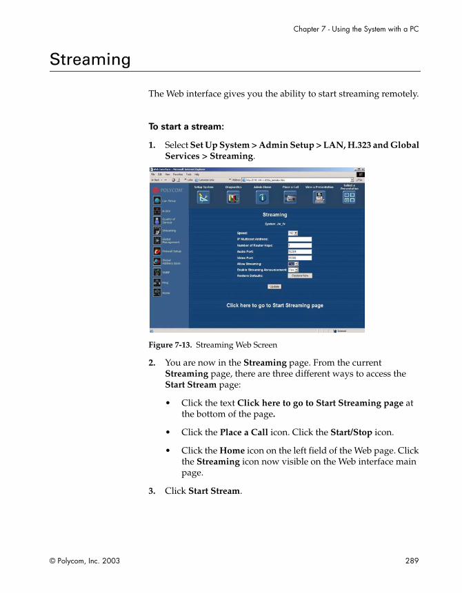
Chapter 7 - Using the System with a PC
© Polycom, Inc. 2003 289
Streaming
The Web interface gives you the ability to start streaming remotely.
To start a stream:
1. Select Set Up System > Admin Setup > LAN, H.323 and Global Services > Streaming.
Figure 7-13. Streaming Web Screen
2. You are now in the Streaming page. From the current Streaming page, there are three different ways to access the Start Stream page:
• Click the text Click here to go to Start Streaming page at the bottom of the page.
• Click the Place a Call icon. Click the Start/Stop icon.
• Click the Home icon on the left field of the Web page. Click the Streaming icon now visible on the Web interface main page.
3. Click Start Stream.

ViewStation FX/VS4000 User Guide
290 www.polycom.com

© Polycom, Inc. 2003 291
8Troubleshooting
This chapter provides detailed troubleshooting information.
For basic troubleshooting information refer to Troubleshooting in chapter 1.
You may also want to refer to theDiagnostics Screen Reference section in Appendix A to find out how to perform various diagnostic tests that can help you troubleshoot any issues.
Topics in This Chapter
The following troubleshooting categories are included in this chapter.
Category Page
General 292
Audio 293
Video 295
Network and Communications 297
IMUX 299
LAN/Intranet 300
Presentations 301
Remote Control 303
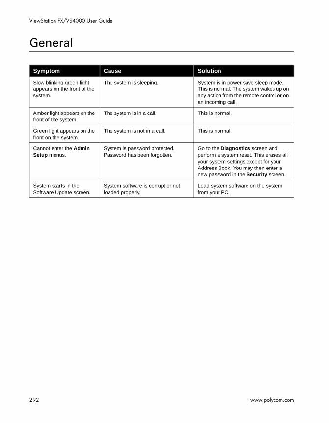
ViewStation FX/VS4000 User Guide
292 www.polycom.com
General
Symptom Cause Solution
Slow blinking green light appears on the front of the system.
The system is sleeping. System is in power save sleep mode. This is normal. The system wakes up on any action from the remote control or on an incoming call.
Amber light appears on the front of the system.
The system is in a call. This is normal.
Green light appears on the front on the system.
The system is not in a call. This is normal.
Cannot enter the Admin Setup menus.
System is password protected. Password has been forgotten.
Go to the Diagnostics screen and perform a system reset. This erases all your system settings except for your Address Book. You may then enter a new password in the Security screen.
System starts in the Software Update screen.
System software is corrupt or not loaded properly.
Load system software on the system from your PC.

Chapter 8 - Troubleshooting
© Polycom, Inc. 2003 293
Audio
Symptom Cause Solution
Not enough volume during a call.
The volume is set too low on the system.
Turn up the system volume using the remote control.
The volume is set too low on the monitor.
Turn up the volume on your monitor or external amplifier.
The microphone pod is too far from the people speaking.
Move the microphone pod closer to the meeting participants.
The system startup music plays through the built-in system speaker but not through monitor speakers.
The monitor speakers or audio amplifier are not properly connected.
Check audio connections and volume level on your monitor.
Incoming call ring and other sound effects too loud or too soft.
The sound effects volume is not set at desired level.
Adjust the sound effects volume on the Phone/Audio screen. If you do not want to hear sound effects, set the volume to 0.
No audio in a call. The monitor audio inputs are not connected properly.
Check audio output on the Generate Tone screen under Diagnostics. You should hear a 400 Hz tone emitting from the speaker.
The system is connected to the wrong audio input on the monitor.
Make sure the system audio output lead(s) are connected to the same input connector(s) that have been selected on the monitor.
The far site is muted. Look for the far site Mute icon. Ask the far site to unmute its microphone pod.
Too many network line errors. Disconnect call and reconnect later.

ViewStation FX/VS4000 User Guide
294 www.polycom.com
The microphone pod is not positioned correctly.
Make sure that the microphone pod is positioned correctly for the meeting configuration. If the microphone pod is behind the meeting participants, you may not be able to hear them speak. For the best audio, always position the microphone pod between the monitor and the person closest to the monitor. As most people face the monitor during a call, following this rule ensures that the meeting participants are also facing the microphone pod.
You can also daisy-chain microphone pods along the conference table. Follow the same rule for multiple microphone pods and do not position the pods behind the meeting participants.
Audio clipping at far site when using an external wireless microphone.
The audio input is overdriven on the system.
Turn down output of wireless microphone. Put the system in local loop and adjust microphone output until you hear audio coming back clear and crisp with no clipping.
Local audio can be heard when speaking in the microphone.
The monitor or audio amplifier is connected to the VCR audio output.
Connect the monitor or audio amplifier to the monitor audio out of the system.
An echo is heard at the near site when speaking.
The far site microphone pod is too close to the audio speaker.
At the far site, make sure the microphone pod is placed away from the audio speaker.
The far site audio volume may be too loud.
Turn down the audio volume at the far site.
Near site or far site cannot hear or see the VCR audio.
The VCR input is not selected. Turn on the VCR input by selecting the NEAR key twice and selecting the VCR icon.

Chapter 8 - Troubleshooting
© Polycom, Inc. 2003 295
Video
Symptom Cause Solution
Picture is blank on the main monitor.
The system goes to “sleep” mode after 3 minutes of inactivity.
Pick up the remote control to wake up the system.
Same picture is seen on the first and second monitor.
Only one monitor is enabled. Enable the system for two monitors on the Monitor Setup screen.
The monitors are connected to the same output. The monitor has a composite as well as an S-Video output.
Connect Monitor 2 to the Monitor 2 connection on the rear panel of the system.
Picture freezes frequently during a call.
The network line transmission errors or IP LAN traffic is too high. Check the error count under the Diagnostics screen or try a lower speed IP call.
Check your system using the Near End Loop test under the Diagnostics screen. If the picture does not freeze, tell the far site to perform the same test. If the picture freezes, there are line errors on your ISDN lines.
You can also test this by placing a video call to an ISDN loopback number provided by your service provider.
Picture is slow or jerky. Only one 64 Kbps channel is connecting in your call.
Check the ISDN number of the far site. Ask the far site to call your site.
Lots of motion in the picture you are receiving.
A background with less motion provides a better, smoother video picture.

ViewStation FX/VS4000 User Guide
296 www.polycom.com
Camera voice tracking does not work properly.
The camera tracking was turned off by near or far site.
Camera tracking is turned off when the near or far site moves your camera. Press the AUTO button on the remote control to restore tracking.
Environmental factors, such as hard surfaces, large windows, hard floors, and the way the unit is mounted on a wall or alcove can fool voice tracking.
The far site is speaking. The camera stops tracking when the far site speaks to prevent the camera from pointing to your monitor speaker.
The far site is very noisy. The camera stops tracking when the far site has a loud noise. Try setting the system to track to camera presets.
The near site is on mute. The near site camera does not track when the near site is on mute. Toggle mute function with the MUTE button on the remote control.
Near-site is noisy or too many people talking at once.
Reduce the noise in the room.
Blue screen in the PIP window.
No video input. Check that there is a video source present on the selected input.
The camera selection is incorrect Check camera selection on the Camera screen.
The VCR input is selected and the VCR is idle or not running. Most VCRs generate a blue screen when the tape is not playing.
Select a different input on the system or play a tape on the VCR.
Near site camera does not pan or tilt.
You are attempting to move a camera that does not have pan/tilt/zoom capabilities.
Make sure you have selected a pan/tilt/zoom camera.
In a multipoint call, the system MCU displays a picture of a telephone instead of video for a particular endpoint.
To indicate that a particular endpoint which cannot downspeed at the correct data rate is admitted to the multipoint call as an audio call only, the system MCU displays a picture of a telephone in the screen area corresponding to that endpoint call.
This is normal.

Chapter 8 - Troubleshooting
© Polycom, Inc. 2003 297
Network and Communications
Symptom Cause Solution
Error message occurs when dialing a video call.
If this is an H.320 call, the first line did not connect. It cannot make a call if the first line does not connect.
Check that all network cables are properly connected. Restart the system.
Try to call alternate sites.
If this is an H.323 call, the IP Gateway/Gatekeeper is not operating or is not configured correctly.
Contact your network administrator.
ISDN: Line Status icons do not go away so video calls cannot be made.
The ISDN line is not present. Check the ISDN line connections. The system has an S/T interface and requires an NT-1 to be connected between the the system and your ISDN line, unless the system is connected to a PBX. See below.
The ISDN number is entered incorrectly.
Check the ISDN numbers with your service provider.
The SPID numbers are entered incorrectly. Note: The AT&T point-to-point protocol does not require SPIDs.
Select the Clear icon on the Auto Detect SPIDs page, and then select the Start icon to automatically detect the new SPIDs. Make sure your ISDN numbers are entered correctly.
The system is directly connected to a U interface.
Install an NT-1 between your ISDN line and the ViewStation ISDN connection.
ISDN: The Line Status icons do not go away so video calls cannot be made.
The ViewStation is connected to an NT-1 then directly to a PBX. The PBX connection is an S/T interface.
You do not need an NT-1 when connecting to a PBX. Connect the system directly to the PBX S/T connection. You may need to use an ISDN terminating resistor on the ISDN line between your ViewStation and the PBX.

ViewStation FX/VS4000 User Guide
298 www.polycom.com
Your ISDN line is provisioned incorrectly by your service provider.
The system will auto-detect SPIDs for about 85% of all United States and Canadian switches. The ViewStation was not able to detect your SPIDs.
Check that your ISDN line is provisioned for Voice/Data, Voice Data.
Check that your ISDN line is provisioned for Voice/Data, Voice/Data.
Check with your ISDN service provider and enter the SPIDs and switch protocol manually. Note: The AT&T point-to-point protocol does not require SPIDs.
You may want to contact your ISDN provider and ask him to switch your line to the NI 1 protocol standard.
ISDN: Error message when dialing a video call.
An ISDN error code is received from the ISDN line.
Refer to the Integrators’ Reference Manual for ViewStation EX, ViewStation FX, and VS4000.
ISDN: When placing a call, progress icons do not turn green.
The call progress icons indicate that the video call did not complete.
The call progress icons indicate the call state when placing or receiving a video call on each ISDN channel:
Blue: call initiated
Yellow: call arrived at the far end ISDN switch
Orange: remote system answered call
Green: video sync OK
System is waiting for an IP address. The System Info screen shows “waiting” in IP address field.
The LAN is not working. Check the connections to the hub. Contact your network administrator.
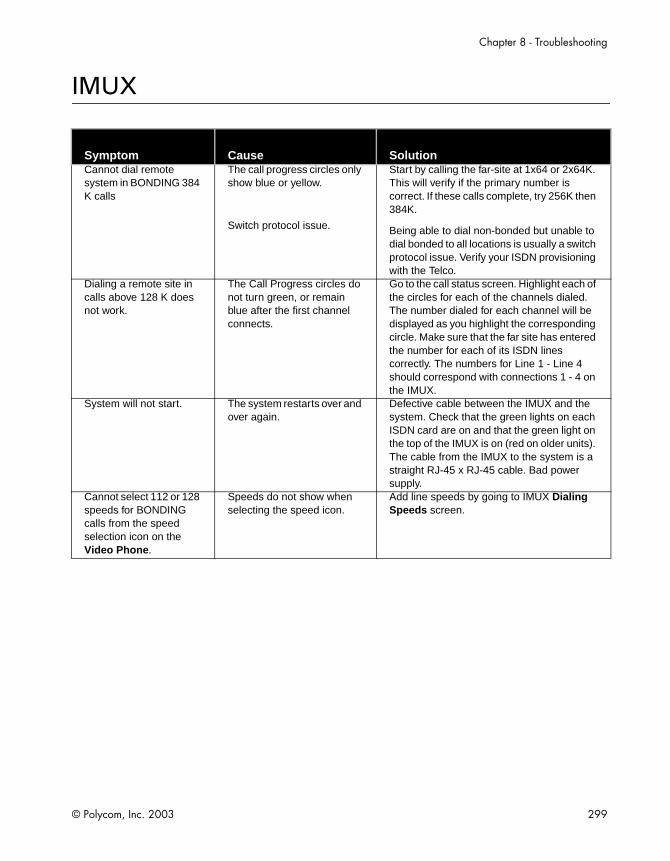
Chapter 8 - Troubleshooting
© Polycom, Inc. 2003 299
IMUX
Symptom Cause SolutionCannot dial remote system in BONDING 384 K calls
The call progress circles only show blue or yellow.
Switch protocol issue.
Start by calling the far-site at 1x64 or 2x64K. This will verify if the primary number is correct. If these calls complete, try 256K then 384K.
Being able to dial non-bonded but unable to dial bonded to all locations is usually a switch protocol issue. Verify your ISDN provisioning with the Telco.
Dialing a remote site in calls above 128 K does not work.
The Call Progress circles do not turn green, or remain blue after the first channel connects.
Go to the call status screen. Highlight each of the circles for each of the channels dialed. The number dialed for each channel will be displayed as you highlight the corresponding circle. Make sure that the far site has entered the number for each of its ISDN lines correctly. The numbers for Line 1 - Line 4 should correspond with connections 1 - 4 on the IMUX.
System will not start. The system restarts over and over again.
Defective cable between the IMUX and the system. Check that the green lights on each ISDN card are on and that the green light on the top of the IMUX is on (red on older units). The cable from the IMUX to the system is a straight RJ-45 x RJ-45 cable. Bad power supply.
Cannot select 112 or 128 speeds for BONDING calls from the speed selection icon on the Video Phone.
Speeds do not show when selecting the speed icon.
Add line speeds by going to IMUX Dialing Speeds screen.

ViewStation FX/VS4000 User Guide
300 www.polycom.com
LAN/Intranet
Symptom Cause Solution
Cannot access the system from the PC browser.
DHCP Client is ON and no DHCP server is available.
Contact your network administrator.
The LAN cable is connected to the PC port.
Connect the LAN cable to the LAN port on the rear of the system.
Bad LAN cable. Check the light on the back of the system. You should have a steady green light to indicate a connection to the LAN and a flashing orange light to indicate LAN traffic.
There is a firewall between your PC and your system.
Consult your network administrator.
Your PC is on a different subnet and there is a router between you and your system.
Change your PC or system subnet mask and IP address so that they are both on the same LAN or subnet.
System does not allow management via the Web.
Wrong password. Enter the correct password. Note: The default password is “admin.”
Too many managers are logged into the system.
Only two system managers are allowed at any one time. To log everyone out, restart your system.

Chapter 8 - Troubleshooting
© Polycom, Inc. 2003 301
Presentations
Symptom Cause Solution
Web browser does not allow showing PowerPoint presentations from the PC to the system.
Wrong version of Web browser. Presenting PowerPoint slides works with Internet Explorer 5.5 on Windows 98, ME, and 2000. You may need to load service packs to your browser. This function does not work with Netscape.
Internet Explorer must have Active-X enabled. It is a requirement of PC Present.
PowerPoint presentation does not export.
Wrong version of Microsoft Office. Use Microsoft Office 97 or 2000.
Insufficient disk space. Slides are converted to JPEG files and are stored in the Windows/Temp directory on your PC. Create more room on your PC.
There are too many presentations on the system. Only eight presentations are allowed.
Delete some presentations from the system and restart the system.
Presentation is too large. Separate large presentations into two smaller presentations.
Cannot connect to the PC from the system for presentation. The PC name is there but the PC presentation cannot be accessed when the slide button is pressed.
Incorrect password. Enter the correct password that was entered on the PC.
Firewall between the system and the PC.
Consult your IT manager.
Too many presenters. The system allows a maximum of eight presenters or PCs to be logged on at one time.
Have extra presenters disconnect.
Snapshots and presentations cannot be viewed, though the PC has access to the main Web page of the system.
Too many viewers logged in. The system supports up to 30 viewers via the Web browser in a call.
Have extra viewers disconnect.
Change the slide-viewing password on the Security screen to allow only authorized viewers.
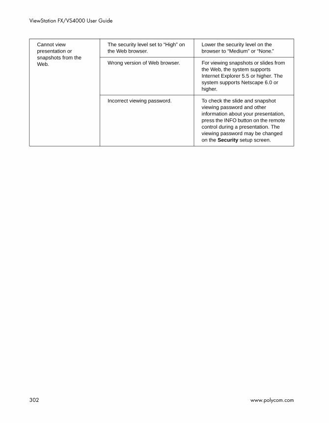
ViewStation FX/VS4000 User Guide
302 www.polycom.com
Cannot view presentation or snapshots from the Web.
The security level set to “High” on the Web browser.
Lower the security level on the browser to “Medium” or “None.”
Wrong version of Web browser. For viewing snapshots or slides from the Web, the system supports Internet Explorer 5.5 or higher. The system supports Netscape 6.0 or higher.
Incorrect viewing password. To check the slide and snapshot viewing password and other information about your presentation, press the INFO button on the remote control during a presentation. The viewing password may be changed on the Security setup screen.

Chapter 8 - Troubleshooting
© Polycom, Inc. 2003 303
Remote Control
Symptom Cause Solution
System does not respond to the hand-held remote control.
No batteries in the remote control. The green light at the front of the system should blink with each button pressed on the remote. control.
Batteries installed incorrectly. Insert batteries with correct +/- position.
The room lights operate in the 38 khz range and interfere with the remote control lights.
Try turning off the lights in the room and try the remote control again.
Low battery icon on the screen.
Low battery in the remote control. Replace the batteries in the remote control with 3 AAA batteries.

ViewStation FX/VS4000 User Guide
304 www.polycom.com
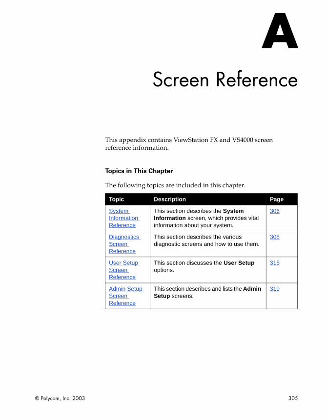
© Polycom, Inc. 2003 305
AScreen Reference
This appendix contains ViewStation FX and VS4000 screen reference information.
Topics in This Chapter
The following topics are included in this chapter.
Topic Description Page
System Information Reference
This section describes the System Information screen, which provides vital information about your system.
306
Diagnostics Screen Reference
This section describes the various diagnostic screens and how to use them.
308
User Setup Screen Reference
This section discusses the User Setup options.
315
Admin Setup Screen Reference
This section describes and lists the Admin Setup screens.
319
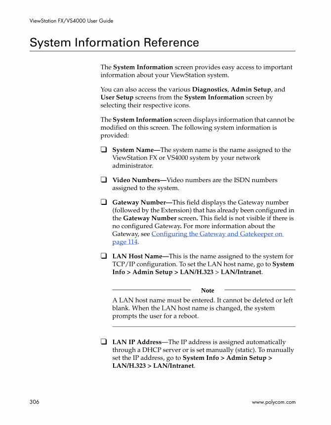
ViewStation FX/VS4000 User Guide
306 www.polycom.com
System Information Reference
The System Information screen provides easy access to important information about your ViewStation system.
You can also access the various Diagnostics, Admin Setup, and User Setup screens from the System Information screen by selecting their respective icons.
The System Information screen displays information that cannot be modified on this screen. The following system information is provided:
❑ System Name—The system name is the name assigned to the ViewStation FX or VS4000 system by your network administrator.
❑ Video Numbers—Video numbers are the ISDN numbers assigned to the system.
❑ Gateway Number—This field displays the Gateway number (followed by the Extension) that has already been configured in the Gateway Number screen. This field is not visible if there is no configured Gateway. For more information about the Gateway, see Configuring the Gateway and Gatekeeper on page 114.
❑ LAN Host Name—This is the name assigned to the system for TCP/IP configuration. To set the LAN host name, go to System Info > Admin Setup > LAN/H.323 > LAN/Intranet.
Note
A LAN host name must be entered. It cannot be deleted or left blank. When the LAN host name is changed, the system prompts the user for a reboot.
❑ LAN IP Address—The IP address is assigned automatically through a DHCP server or is set manually (static). To manually set the IP address, go to System Info > Admin Setup > LAN/H.323 > LAN/Intranet.

Appendix A - Screen Reference
© Polycom, Inc. 2003 307
❑ Software Version—The software version and the date of the software release are displayed in this field. Additional information about the system software version is located in System Info > Admin Setup > Software/Hardware > Software.
❑ Serial Number—The serial number is unique to each system. This number is also located on a bar code sticker on the bottom of the unit. This number cannot be modified.
❑ Model—The system model type is displayed.
The Diagnostics, User Setup, and Admin Setup icons are displayed at the bottom of the screen. These icons link to screens where you can perform various setup and diagnostic tasks.

ViewStation FX/VS4000 User Guide
308 www.polycom.com
Diagnostics Screen Reference
You can view network statistics and perform various diagnostic tests on your ViewStation FX or VS4000 system from the following diagnostics screens:
❑ Network Statistics
❑ Advanced Network Statistics
❑ Call Status
❑ Color Bars
❑ Audio
❑ Near End Loop
❑ Reset System
These screens are described in the following sections.
Note
You can also view statistics and run these diagnostic tests from the system’s Web interface. For information on how to do this, refer to System Diagnostics in chapter 7.
Network Statistics
The Network Statistics screen displays the network protocols and data speeds at which your call will travel over the network to the far site.
To access the Network Statistics screen:
Select System Info > Diagnostics > Network Stats.
This screen displays information about:

Appendix A - Screen Reference
© Polycom, Inc. 2003 309
❑ Tx (transmitting) and Rx (receiving) Clock Rates and Errors.
❑ Sync—The - or + sign shows that the system is synchronized with another T.120 device, such as a Polycom ShowStation.
❑ Video Protocol—ITU video algorithm and annexes being used.
❑ Video Format—CIF, Wide screen, etc.
❑ Audio Protocol—G.711, G.722, or G.728.
❑ Comm Protocol—ISDN (H.320) or IP (H.323).
Advanced Network Statistics
The Advanced Network Statistics screen displays detailed information about the status of your call. Transmit and receive speeds are displayed for both audio and video during a call.
To access the Advanced Network Statistics screen:
Select System Info > Diagnostics > Advanced Stats.
This screen displays information about:
❑ Audio Rate—Amount of bandwidth dedicated to audio (regulated by the audio algorithm in use).
❑ Video Rate—Total bandwidth of call minus audio bandwidth.
❑ Video Rate Used—Actual bandwidth being used for video at that moment. It will fluctuate and even peak above the Video Rate number.
❑ Video Frame Rate—Usually near 15, 30, or 60 fps. It will fluctuate based upon lighting and movement of camera or people.
❑ Video FEC Errors—Number of received video FEC frames containing at least one error since the beginning of the call. FEC (Forward Error Correction) is used to detect and correct errors.
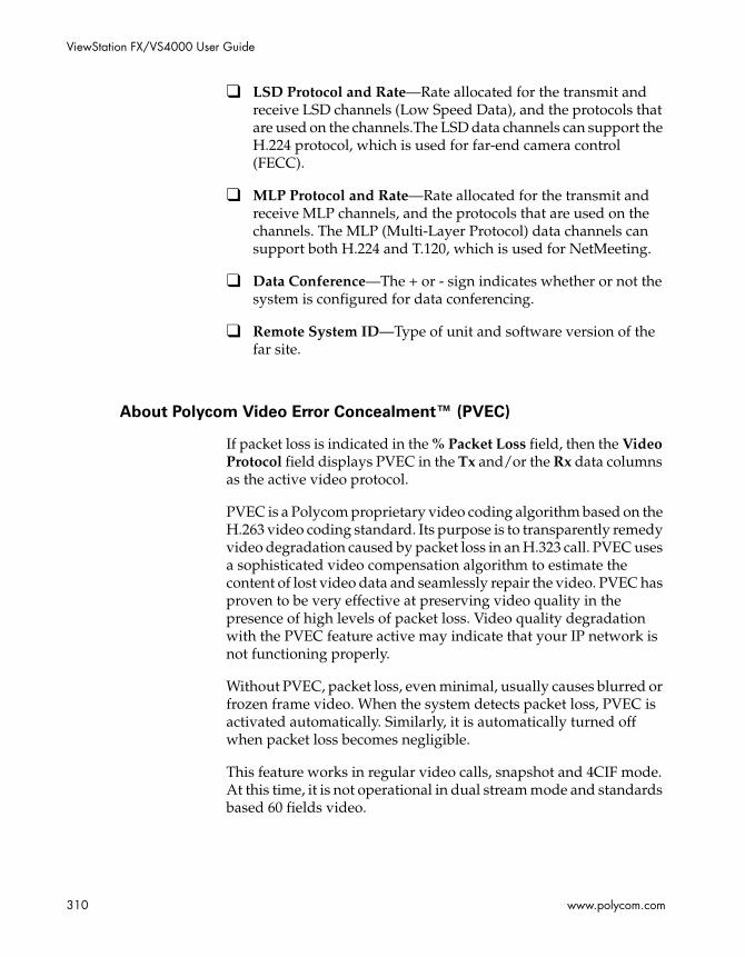
ViewStation FX/VS4000 User Guide
310 www.polycom.com
❑ LSD Protocol and Rate—Rate allocated for the transmit and receive LSD channels (Low Speed Data), and the protocols that are used on the channels.The LSD data channels can support the H.224 protocol, which is used for far-end camera control (FECC).
❑ MLP Protocol and Rate—Rate allocated for the transmit and receive MLP channels, and the protocols that are used on the channels. The MLP (Multi-Layer Protocol) data channels can support both H.224 and T.120, which is used for NetMeeting.
❑ Data Conference—The + or - sign indicates whether or not the system is configured for data conferencing.
❑ Remote System ID—Type of unit and software version of the far site.
About Polycom Video Error Concealment™ (PVEC)
If packet loss is indicated in the % Packet Loss field, then the Video Protocol field displays PVEC in the Tx and/or the Rx data columns as the active video protocol.
PVEC is a Polycom proprietary video coding algorithm based on the H.263 video coding standard. Its purpose is to transparently remedy video degradation caused by packet loss in an H.323 call. PVEC uses a sophisticated video compensation algorithm to estimate the content of lost video data and seamlessly repair the video. PVEC has proven to be very effective at preserving video quality in the presence of high levels of packet loss. Video quality degradation with the PVEC feature active may indicate that your IP network is not functioning properly.
Without PVEC, packet loss, even minimal, usually causes blurred or frozen frame video. When the system detects packet loss, PVEC is activated automatically. Similarly, it is automatically turned off when packet loss becomes negligible.
This feature works in regular video calls, snapshot and 4CIF mode. At this time, it is not operational in dual stream mode and standards based 60 fields video.

Appendix A - Screen Reference
© Polycom, Inc. 2003 311
Call Status
The Call Status screen displays call status indicators for each channel used in a call. On this screen, you can determine if any channels are failing in a call. If you highlight one of the call progress indicators, the corresponding call number for that channel appears. You can compare this number with the number you dialed, or you can check for a malfunctioning channel.
To access the Call Status screen:
Select System Info > Diagnostics > Call Status.
A single channel will appear for IP calls regardless of the speed of the call.
Color Bars
The Color Bars diagnostic screen allows you to set the monitor controls for the optimum picture quality. If the color bars that are generated do not look clear, or the colors do not look correct, the monitor needs to be adjusted.
To access the Color Bars screen:
Select System Info > Diagnostics > Color Bar.
To test the color setting on your television monitor:
1. Highlight the View Color Bars icon.
2. Press the SELECT button on the remote control. Color bars appear full screen.
3. Use the controls on the television monitor to adjust the color settings.
4. Press any button on the remote control to return to the Color Bars screen.

ViewStation FX/VS4000 User Guide
312 www.polycom.com
Audio
The Generate Tone and Audio Meter diagnostic screens allow you to test your audio connections. They are accessed from the Audio screen.
To access the Audio screen:
Select System Info > Diagnostics > Audio. From the Audio screen, you can access the Generate Tone and the Audio Meter screens.
Generate Tone
The Generate Tone diagnostic screen is used to test if the audio connections to the monitor are correct. A 400 MHz audible tone should be heard from the monitor speakers indicating the local audio connections are correct.
There is an animated speaker icon that indicates a tone is being emitted, whether or not a tone is heard. If no tone is heard, the audio connections to the monitor are incorrect.
To generate a tone:
1. Highlight the Generate Tone icon and press the SELECT button on the remote control.
2. The Generate Tone screen appears with instructions on how to perform this test.
3. Highlight the Generate Tone icon again press the SELECT button on the remote control.
4. When you hear the tone, adjust the volume controls on your system and television monitor to comfortable levels.
5. Press any button to stop the tone.
Note
If the system is in a call the far site also hears the tone.

Appendix A - Screen Reference
© Polycom, Inc. 2003 313
Audio Meter
The Audio Meter screen is used to test external audio input in custom installations. If, at normal speaking levels, the audio meter does not register between 0 and 15, try positioning yourself closer to the microphones or adjusting the settings on your line device or mixing board.
To test audio levels:
1. Highlight the Audio Meter icon and press the SELECT button on the remote control. The Audio Meter screen indicates the audio level of all audio inputs connected to the system.
2. Speak into the microphone to test the audio level.
Near End Loop
The Near End Loop screen allows you to see how a far site would see and hear you. This can help you diagnose a problem with an H.320 video call.
To access the Near End Loop screen:
Select System Info > Diagnostics > Near End Loop.
The Near End Loop screen allows you to test the encoder/decoder on your ViewStation FX or VS4000 system. If you perform a near-end loop test during a call, the far site sees a loop of itself. Press any button on the remote control to stop the loop.
Note
This diagnostic tool is only available out of a call or in a H.320 call.

ViewStation FX/VS4000 User Guide
314 www.polycom.com
Far End Loop
The Far End Loop screen allows you to find out whether or not your audio and video is going out across the network and coming back properly. This diagnostic tool is only available in an H.320 call.
To access the Far End Loop screen:
Select System Info > Diagnostics > Far End Loop.
Reset System
The Reset System screen clears existing system configurations. You can erase your system settings, your admin password, and/or your Address Book entries. Once you have reset the system, your system walks you through the system configuration screens as it did when you powered it on for the first time.
To access the Reset System screen:
Select System Info > Diagnostics > Reset System.
To reset the system:
1. Enter the system’s serial number.
2. Make sure the Delete System Settings option is selected.
3. Select the Reset button.
Note
Be sure to copy system information before resetting a system. All settings are lost when you reset the system. Passwords are set on your system’s user interface. If you forget the admin password, this screen will allow you to reconfigure the system with a new password.

Appendix A - Screen Reference
© Polycom, Inc. 2003 315
User Setup Screen Reference
The User Setup screen is used to set user preferences that can be made every time the system is used. None of these items require a system reboot to take effect.
Note
This screen is not password protected, however, access to this screen may be eliminated by disabling the Allow User Setup option in the General Setup screen.
To access the User Setup screen:
Select System Info > User Setup:
Figure A-1. User Setup Screen
You can use the User Setup screen to set the following options:
❑ Auto Answer Point to Point—This option lets you set the Auto Answer mode for a point-to-point call.
To set the mode, select the appropriate option from the drop-down menu in the Auto Answer Point to Point field. These options are No, Yes, and Do Not Disturb; they are described below:

ViewStation FX/VS4000 User Guide
316 www.polycom.com
• Yes—If Auto Answer Point to Point is set to Yes, any incoming call will be connected automatically. In a point-to-point call, the default is Yes.
• No—If Auto Answer Point to Point is set to No, the user will be prompted with a message "You have a video call. Would you like answer?" if there is an incoming call. This is generally followed by a video number and a far-site name if they are available. If the user selects Yes, the call will be connected. If the user selects No, the call will be rejected.
• Do Not Disturb—If Auto Answer Point to Point is set to Do Not Disturb, the user is not notified when there is an incoming call. The site which placed the call will receive either a “call rejected” or “dialed site busy” message.
❑ Auto Answer Multipoint—This setting is used to determine how the system will handle an incoming call in a multipoint video conference. This setting only matters if the system is in a call.
Select the appropriate option from the drop-down menu in the Auto Answer Multipoint field. These options are No, Yes, and Do Not Disturb and are described below:
• No—If Auto Answer Multipoint is set to No and there is an incoming call, the user will be prompted with a message "You have a video call. Would you like answer?" if there is an incoming call. This is generally followed by a video number and a far-site name if they are available. If the user selects Yes, the call will be added into the ongoing conference. If the user selects No, the call will be rejected. The factory default is set to No.
• Yes—If Auto Answer Multipoint is set to Yes, any incoming call will be connected automatically. The screen will split into a multipoint call progress screen as the incoming call is answered.
• Do Not Disturb—If Auto Answer Multipoint is set to Do Not Disturb, the user is not notified of the incoming call. The site which placed the call receives a Far Site Busy code (H.320) or Call Rejected (H.323)
❑ Mute Auto Answer Calls—When this option is selected, the microphone pod is turned off to prevent the far site from
Appendix A - Screen Reference
© Polycom, Inc. 2003 317
hearing the near site when the system is in Auto Answer mode. Both sites are notified that the system is muted with a microphone image located in the lower left side of the main screen. A red light illuminates on the microphone pod when the near site is muted.
Note
If the system is already in a call, the Mute Auto Answer Calls option does not automatically mute the near site.
❑ PIP—The PIP (Picture in Picture) feature allows the near site to adjust near-camera views while in a videoconference. When PIP is enabled, the Camera icon in the top right corner of the screen disappears when the remote control is placed on a flat surface.The following options are available in PIP mode:
• Auto—The system shows a PIP window when the call is first connected and when the remote control is not resting on a flat surface.
• On—The system shows a PIP window which remains in the lower right corner until the video call is completed.
• Off—The system does not show a PIP window.
❑ Far Control of Near Camera—This option allows users on the far site to control the camera at the near end. When this option is enabled, a far-site user may control the framing and angle of the camera of the near site by pressing the FAR button on the remote control.
❑ Backlight Compensation—Backlight compensation is used in conference rooms where the subject appears darker than the background. When enabled, the camera automatically adjusts for a light background.
❑ Allow Remote Monitoring—Remote monitoring allows a user to remotely view a conference room prior to a scheduled meeting using the system’s Web interface.
❑ Meeting Password—The meeting password is used:
• As the system’s password when it it is used as an MCU.

ViewStation FX/VS4000 User Guide
318 www.polycom.com
• For dialing into an MCU with a password already set.
• As the password for viewing slides on the Web interface.
• As the password for viewing streams on the Web interface.
• For accessing Closed Caption.
❑ Far Site Name Display Time—This option displays the name of the far site for a defined number of seconds.
• 15 seconds—The far site name is displayed by default for 15 seconds.
• Blank—The far site name is displayed until the call is ended.
❑ Multipoint Mode—To change Multipoint Mode, highlight the Multipoint Mode field and press the SELECT button on your remote control. The Multipoint Setup screen appears. In the Multipoint Setup screen, you can set the Multipoint Mode to Auto, Discussion, Presentation, or Full Screen. By default, it is set to Auto. For more information about multipoint modes, refer to Multipoint Viewing Modes in chapter 6.
You can also set the Auto Answer Multipoint mode in the Multipoint Setup screen. For more information, refer to Auto Answer Multipoint at the beginning of this section on page 316.

Appendix A - Screen Reference
© Polycom, Inc. 2003 319
Admin Setup Screen Reference
You can access all the system screens from their respective icons on the Admin Setup screen. These screens are used to view or modify the setup of your ViewStation FX or VS4000 system.
To access the Admin Setup screen:
Select System Info > Admin Setup.
Figure A-2. Admin Setup Screen
Select the icon of the setup screen where you want to view or change options and press the SELECT button on the remote control.
You can also view and change the setup of your system from its Web interface. For more information, see Admin Setup/General Setup on page 282 in chapter 7.
Tip
At any time, you can return to the previous screen by pressing the MENU button on the remote control. Press the CALL•HANG-UP button to return to the main screen.
The following sections describe the screens grouped under the Admin Setup icon screen.
ViewStation FX/VS4000 User Guide
320 www.polycom.com
General Setup
This screen contains basic information about your system. It also allows you to change some of the system settings.
To access the General Setup screen:
Select System Info > Admin Setup.
On this screen, you can change the following General Setup options:
❑ Language—Select the language field to access the Welcome screen where the language flags are displayed. Select the appropriate flag associated with the language you wish to use in the system’s user interface.
❑ Country—Click the Country field to access the Country Setup screen.
The fields in the Country Setup screen allow you to select the country where the system is located. It also allows you to specify country-specific calling parameters for your location.
❑ System Name—Enter a name for the system using the on-screen keyboard. The first character has to be a numeric (a digit) or alphabetic (a letter) character including foreign language characters. The name can be any combination of alphanumeric characters up to 34 characters in length.
❑ Auto Answer Point to Point—This option allows you to set the Auto Answer mode for a point-to-point videoconference. It lets you determine how the system will handle an inbound call. For more detailed information about this option, refer to User Setup Screen Reference, on page 315.
❑ Auto Answer Multipoint—This option allows you to set the Auto Answer mode for a multipoint videoconference. It lets you determine how the system will handle an inbound call. For more detailed information about the Auto Answer Multipoint mode and the Dial-In Calling feature, refer to Dial-In Calling.
❑ Allow Dialing—Enable this option to allow users to place calls from the system. If this option is disabled, the system can only receive calls. You can still place calls from the Web interface.

Appendix A - Screen Reference
© Polycom, Inc. 2003 321
❑ Display IP and ISDN Information—Select this option if you want your system’s IP address and ISDN numbers displayed on the main user interface for ease of use. If your system is IP only, registered with a Gatekeeper, and has a Gateway number, this number is displayed as your ISDN number on the main screen. This option is enabled by default.
❑ Maximum Time in Call—Enter the maximum number of minutes allowed for call length. When that time has expired in a call, you see a message asking you if you want to hang up or stay in the call. If you do not answer within one minute, the call automatically disconnects. If you want your call to stay up indefinitely, delete the time setting in the Maximum Time in Call field. Make sure to do the same on all videoconferencing endpoints in that call so that the call never times out.
❑ Allow User Setup—This option is used to enable or disable the User Setup icon on the System Info screen. Administrators can use this option to prevent users from changing the User Setup functions.
❑ Allow Address Book Changes—If this option is enabled, then the user has access to the New, Edit, and Delete icons in the Address Book screen.
❑ Keypad Audio Confirmation—This option enables an audio response (English language) when a numeric key is depressed on the remote control.
❑ Display Speed Dial—This option allows you to disable the Speed Dial screen. When it is disabled, you access the Address Book directly.
❑ Screen Saver Wait Time—This option allows users to set the system screen saver sleeping time. The default is 15 minutes.
V.35/RS-449/RS-530 Video Network Screens
From the main Video Network icon, you can access screens that are specific to the V.35/RS-449/RS-530 network interface, as listed below.
ViewStation FX/VS4000 User Guide
322 www.polycom.com
To access the main Video Network screen:
Select System Info > Admin Setup > Video Network.
Multipoint Setup
See Multipoint Viewing Modes on page 223.
Call Preferences
See Setting your Call Preferences on page 74.
Note
When you enable the LAN/Internet Calls (H.323) option in the Call Preferences screen, your system resets itself automatically and takes you through the initial configuration screens (see Initial Setup for IP (H.323) Calls on page 76). Existing system information is not erased during this process.
Video Network
See Setting Video Network Options on page 81. From the Video Network screen, you can also access the Dialing Speeds, Broadcast Mode, and Advanced Dialing configuration screens.
Dialing Speeds
See Selecting Dialing Speeds on page 125.
Broadcast Mode
See Setting up Satellite (H.331) Broadcast Mode on page 123.
Appendix A - Screen Reference
© Polycom, Inc. 2003 323
Advanced Dialing
See Setting the Calling Profile on page 126.
Video Numbers
See Entering V.35/RS-449/RS-530 Video Numbers on page 85.
Advanced V.35
See Configuring the V.35/RS-449/RS-530 Serial Interface Control Signals on page 122.
PRI Video Network Screens
From the main Video Network icon, you can access screens that are specific to the PRI network interface.
To access the main Video Network screen:
Select System Info > Admin Setup > Video Network.
IMUX (Inverse Multiplexer)
The IMUX screen lets you access the PRI Video Numbers screen, the PRI Network screens, the Audio Quality screen, the Advanced Dialing screen, and the Dialing Speeds screen.
PRI Video Numbers
See Entering PRI Video Numbers on page 130.

ViewStation FX/VS4000 User Guide
324 www.polycom.com
PRI Network
From this screen, you can access the PRI Information screen, the PRI Setup screen, and the PRI Status screen.
PRI Information
See Accessing PRI Information (T1 and E1), on page 131 .
PRI Setup
See Setting up PRI Options (T1 and E1), on page 132.
Advanced PRI Setup
See Setting Advanced PRI Options (E1 and T1) on page 136.
PRI Status
See Selecting PRI Channels (E1 and T1) on page 134.
Audio Quality
See Setting Audio Quality Preference on page 138.
Advanced Dialing
See Choosing the Number of Channels to be Dialed in Parallel on page 139.
Dialing Speeds
See Selecting Dialing Speeds on page 140.

Appendix A - Screen Reference
© Polycom, Inc. 2003 325
Call Preference
See Setting your Call Preferences on page 74.
Multipoint Setup
See Multipoint Viewing Modes, on page 223.
Dialing Speeds
See Selecting Dialing Speeds on page 125.
BRI Video Network Screens
From the main Video Network icon, you can access screens that are specific to the BRI network interface.
To access the main Video Network screen:
Select System Info > Admin Setup > Video Network.
IMUX (Inverse Multiplexer)
The IMUX screen lets you access the ISDN Video Numbers screen, the Auto Detect SPIDs screen, the Audio Quality screen, the Advanced Dialing screen, and the Dialing Speeds screen.
ISDN Video Numbers
See Entering ISDN Video Numbers on page 141.
Auto Detect SPIDs
See Entering or Detecting Service Profile Ids on page 142.

ViewStation FX/VS4000 User Guide
326 www.polycom.com
Audio Quality
See Setting Audio Quality Preference on page 144.
Advanced Dialing
See Setting Channel Dialing Preferences on page 145.
Dialing Speeds
See Selecting Dialing Speeds on page 146.
Call Preferences
See Setting your Call Preferences on page 74.
Multipoint Setup
See Multipoint Viewing Modes on page 223.
ISDN Video Network
See Modifying ISDN Video Network Information on page 147.
LAN Setup Screens
From the main LAN/H.323 icon, you can access groups of screens that are used for the LAN and H.323 (IP) setup.
To access the LAN/H.323 screen:
Select System Info > Admin Setup >LAN/H.323.

Appendix A - Screen Reference
© Polycom, Inc. 2003 327
LAN & Intranet (main)
The main LAN & Intranet screen lets you access the LAN & Intranet configuration screen, the Advanced LAN Settings screen, the Firewall & LAN Connection screen.
LAN & Intranet (Configuration)
See Configuring LAN and Intranet Settings on page 103.
Advanced LAN Settings
See Selecting Advanced LAN Settings on page 107.
Firewall & LAN Connection
See Configuring Firewall and LAN Connection Settings on page 109.
H.323 Setup (main)
The main H.323 Setup screen lets you access the H.323 Setup configuration screen, the Dialing Speeds screen, the Gateway and Gatekeeper screen, the Gateway Number screen, and the Gateway Setup screen.
H.323 Setup (configuration)
See Configuring H.323 Name and Extension on page 112.
Dialing Speeds
See Selecting Dialing Speeds on page 113.
ViewStation FX/VS4000 User Guide
328 www.polycom.com
Gateway & Gatekeeper
See Configuring the Gateway and Gatekeeper on page 114.
Gateway Number
See Configuring the Gateway Number on page 118.
Gateway Setup
See Selecting your Gateway Prefix and Suffix on page 119.
Streaming
See Configuring Streaming Preferences on page 165.
SNMP Setup
See Configuring SNMP Preferences on page 167.
Global Address (Main)
The main Global Address screen lets you access the Global Address (Server) configuration screen, the Global Address Book Preferences screen, the Private Network ISDN (PRI) Number screen, the Dialing Rules 1 screen, and the Dialing Rules 2 screen.
Global Address (Server)
See Configuring Settings for the Global Address Book Server on page 149.
Global Address Book Preferences
See Setting the Global Address Book Preferences on page 150.

Appendix A - Screen Reference
© Polycom, Inc. 2003 329
Preferred Alias
See Selecting your Preferred Alias on page 152.
Advanced Address Book Preferences
See Selecting the Call Type Order for OneDial Address Book Entries on page 153.
Private Network ISDN (PRI) Number
See Entering the Private Network Number on page 154.
Dialing Rules 1
See Dialing Rules 1 on page 154.
Dialing Rules 2
See Dialing Rules 2 on page 157.
Global Management (Main)
The main Global Management screen lets you access the Global Management configuration screen, the Global Management URLs screen, and the Global Management Info screen.
Global Management (Configuration)
See Setting Global Management Preferences on page 161.
Global Management URLs
See Accessing Global Management Server URLs on page 162.

ViewStation FX/VS4000 User Guide
330 www.polycom.com
Global Management Info
See Adding Global Management Technical Support Contact Information on page 163.
Quality of Service
See Configuring Quality of Service on page 169.
Data Conference
The ViewStation FX or VS4000 system is T.120-compliant and supports data conferencing when paired with either a ShowStation IP system or Microsoft NetMeeting.
Data conferencing features are available only on point-to-point video calls or with external H.320 bridges/MCUs that support this feature.
Data conferencing is only available during ISDN (H.320) calls and must be supported by far-site systems.
Note
For more information about ShowStation IP, see ShowStation IP in chapter 2. For more information about data conferencing using NetMeeting, refer to NetMeeting in chapter 7.
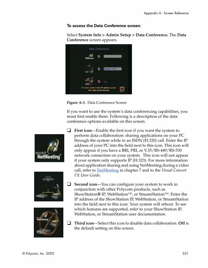
Appendix A - Screen Reference
© Polycom, Inc. 2003 331
To access the Data Conference screen:
Select System Info > Admin Setup > Data Conference. The Data Conference screen appears.
Figure A-3. Data Conference Screen
If you want to use the system’s data conferencing capabilities, you must first enable them. Following is a description of the data conference options available on this screen:
❑ First icon—Enable the first icon if you want the system to perform data collaboration: sharing applications on your PC through the system while in an ISDN (H.320) call. Enter the IP address of your PC into the field next to this icon. This icon will only appear if you have a BRI, PRI, or V.35/RS-449/RS-530 network connection on your system. This icon will not appear if your system only supports IP (H.323). For more information about application sharing and using NetMeeting during a video call, refer to NetMeeting in chapter 7 and to the Visual Concert FX User Guide.
❑ Second icon—You can configure your system to work in conjunction with other Polycom products, such as ShowStation® IP, WebStation™, or StreamStation™. Enter the IP address of the ShowStation IP, WebStation, or StreamStation into the field next to this icon. Your system will reboot. To see which features are supported, refer to your ShowStation IP, WebStation, or StreamStation user documentation.
❑ Third icon—Select this icon to disable data collaboration. Off is the default setting on this screen.

ViewStation FX/VS4000 User Guide
332 www.polycom.com
Telephone & Audio
The Telephone & Audio screen is used to configure the ViewStation FX or the VS4000 system telephone information and audio properties.
To access the Telephone & Audio screen:
Select System Info > Admin Setup > Phone/Audio.
Figure A-4. Telephone & Audio Screen
The following options are displayed on the screen:
❑ System Telephone Number—Enter the Country Code, Area Code, and Number associated with the system telephone number.
❑ Room Telephone Number— You can also enter the telephone number that is assigned to the room where the system is located.
❑ Echo Canceller—This option is enabled by default. It prevents users from hearing their voice loop back from the remote site. Disable this option if another device is providing echo cancellation.
❑ Mute Auto Answer Calls—You can mute or un-mute incoming calls. Incoming calls are muted by default until you press the button on top of the microphone pod or press the mute button on the remote control.
Appendix A - Screen Reference
© Polycom, Inc. 2003 333
❑ Sound Effects Volume—The level of the system sound effects can be set by highlighting this setting and using the volume keys (VOL) on your remote control.
❑ Audio Quality—Select this field to access the Audio Quality Preference screen. This screen can also be accessed from the Audio Quality screen (System Info > Admin Setup > Video Network > IMUX > Audio Quality). In this screen, you can set the call speed threshold that determines which audio protocol is used. For more information about this option and audio error concealment, refer to Setting Audio Quality Preference.
Note
Changing the audio quality preferences in a call can only be done in an H.320 (ISDN) call. No changes can be made while in an H.323 (IP) call.
Video and Cameras Screens
From the main Video and Cameras screen, you can access the Monitors screens, the Cameras screen, the VCR Setup screen, and the VGA Input screen (only if a Visual Concert FX is connected to your system).
To access the Video and Cameras screen:
Select System Info > Admin Setup > Video/Camera.
Monitors
The Monitors screen lets you access the TV Monitors screen and the Graphics Monitor screen.
To access the Monitors screen:
Select System Info > Admin Setup > Video/Camera > Monitors.
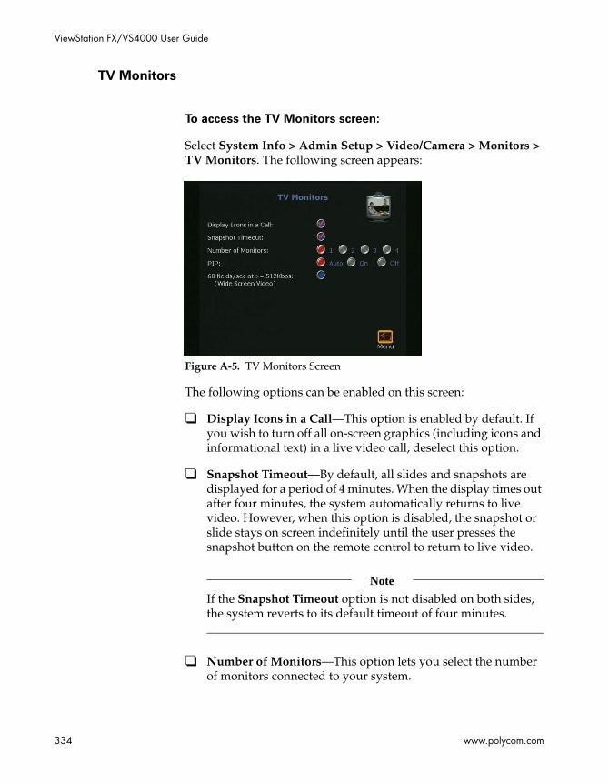
ViewStation FX/VS4000 User Guide
334 www.polycom.com
TV Monitors
To access the TV Monitors screen:
Select System Info > Admin Setup > Video/Camera > Monitors > TV Monitors. The following screen appears:
Figure A-5. TV Monitors Screen
The following options can be enabled on this screen:
❑ Display Icons in a Call—This option is enabled by default. If you wish to turn off all on-screen graphics (including icons and informational text) in a live video call, deselect this option.
❑ Snapshot Timeout—By default, all slides and snapshots are displayed for a period of 4 minutes. When the display times out after four minutes, the system automatically returns to live video. However, when this option is disabled, the snapshot or slide stays on screen indefinitely until the user presses the snapshot button on the remote control to return to live video.
Note
If the Snapshot Timeout option is not disabled on both sides, the system reverts to its default timeout of four minutes.
❑ Number of Monitors—This option lets you select the number of monitors connected to your system.

Appendix A - Screen Reference
© Polycom, Inc. 2003 335
Note
Four monitors can be supported simultaneously in a multipoint call. For more information about this feature, refer to the Integrators’ Reference Manual for ViewStation EX, ViewStation FX, and VS4000.
❑ PIP—This option lets you select a Picture-in-Picture (PIP) mode:
• Auto: If you select Auto, the PIP appears and disappears automatically depending on the position of the remote control.
• On: If you select On, the PIP is displayed continuously.
• Off: If you select Off, the PIP is never displayed.
❑ 60 fields/sec (ITU) at > = 512Kbps (Wide Screen Video)Enable this option to have the monitor display in wide screen video format in IP and ISDN calls at 512 Kbps and above. This option only works between ViewStation FX or VS4000 systems with software version 4.0 and higher. Otherwise, if one of the systems has a software version older than 4.0, the proprietary letter box format is supported.
Graphics Monitor
This screen lets you select the appropriate VGA monitor configuration for your VGA monitor.

ViewStation FX/VS4000 User Guide
336 www.polycom.com
To access the Graphics Monitor screen:
Select System Info > Admin Setup > Video/Camera > Monitors > Graphics Monitor. The following screen appears:
Figure A-6. Graphics Monitor Screen
The following options are available:
❑ TV Monitor—When this option is selected, no VGA monitor is available, and the graphics and video are displayed on the TV monitor.
❑ FX VGA—Enable this option if you have a high-resolution VGA monitor or projector connected to the rear panel of the system. To set up the resolution of your VGA monitor, select Setup.
❑ Visual Concert VGA—Enable this option if a Visual Concert FX unit is connected to your system and the graphics monitor is directly connected to the Visual Concert FX unit. By selecting this option, you enable your system to display your computer desktop on your system’s VGA monitor.
Note
Stop and restart Visual Concert FX when changing graphics monitors: When changes are made to your system to enable different graphics monitors, you need to stop and start the Visual Concert FX unit. If a stream is being played and you choose to

Appendix A - Screen Reference
© Polycom, Inc. 2003 337
enable a different graphics monitor, the stream will not be displayed on the local side unless you stop and start the stream over.
FX VGA Monitor
To access the VGA Monitor screen:
Select System Info > Admin Setup > Video/Camera > Monitors > Graphics Monitor > Setup.
The following two options are available:
❑ VGA Output with No Graphics—Select Black, if you want the screen to turn black when there is no graphics or video. If you select No Signal, the VGA monitor will behave as if the VGA monitor is not connected.
❑ VGA Resolution—Select the VGA Resolution field to access the drop-down selection menu. Select the maximum resolution that your monitor or projector can support. Consult the user manual provided with the VGA monitor or projector for performance.
Cameras (FX)
To access the Cameras screen:
Select System Info > Admin Setup > Video/Camera > Cameras.
The following options are available:
❑ Far Control of Near Camera—When you enable this option, the far site, while in a call can control your camera.
❑ Backlight Compensation—Enable this option if your background is too bright.
❑ Snapshot Camera—This option lets you select the default camera from which you want to send snapshots.

ViewStation FX/VS4000 User Guide
338 www.polycom.com
❑ Camera Direction—This option lets you set the camera to move in the same direction as the arrows on the remote control or in opposite directions.
❑ Primary Camera—This option lets you select the camera that is used when you power on the system. You cannot disconnect the main camera, but you do not have to set it as the primary camera.
❑ High Resolution Cameras—In the High Resolution Cameras field, you can set each of the following graphics input devices to 4CIF (a video resolution standard) by selecting its corresponding number where:
2 = Document Camera
3 = VCR
This option is not available for the primary camera because the higher resolution of 4CIF affects the frame rate quality.
About 4CIF
Both the ViewStation FX and VS4000 system support 4CIF, a video resolution standard defined by 704 pixels per line and 576 lines per video image. 4CIF resolution is four times higher than CIF (352 pixels per line and 288 lines per video image), a standard commonly supported on video communications systems. With 4CIF, more data is transmitted and processed, resulting in crisper images. 4CIF should only be implemented on document cameras or VGA scan converters and is not suggested nor supported for use in live video mode. 4CIF only works between video communications systems supporting this standard. If the receiving system does not support 4CIF, then the transmitting system does not send 4CIF data.
Cameras (VS4000)
The VS4000 Camera Setup screen lets you set up options that are specific to the VS4000 system.

Appendix A - Screen Reference
© Polycom, Inc. 2003 339
To access the VS4000 Camera Setup screen:
Select System Info > Admin Setup > Video/Camera > Cameras > VS4000 Camera Setup. The following screen appears:
Figure A-7. VS4000 Camera Setup Screen
This screen lets you configure your camera equipment for the VS4000 system only. You can connect four cameras to your VS4000. However, you can set three cameras to S-video mode, and two to pan/tilt/zoom mode.
To disable cameras:
1. Set your camera inputs as S-video or composite (VS4000 only), and enable pan/tilt/zoom capability on a camera.
2. Select the appropriate radio button or check circle.

ViewStation FX/VS4000 User Guide
340 www.polycom.com
VCR Setup
To access the VCR Setup screen:
Select System Info > Admin Setup > Video/Camera > VCR. The following screen appears:
Figure A-8. VCR Setup Screen
The VCR Setup screen lets you enable the following options:
❑ VCR Record Source—You can set the VCR Record Source to the following settings:
• Auto: When set to Auto, the VCR automatically records the current speaker in a point-to-point call.
• Near: When Near is selected, the VCR records the near-site presentation.
• Far: When Far is selected, the far-site is recorded. Audio from the near and far sites is always recorded.
❑ VCR Audio Out Always On—When this option is enabled, the system can operate with two VCRs, one for recording and one for play. This also allows the use of the VCR audio out for room audio applications where the near-site and the far-site audio are required with any video input selected.
Notes
1. If you connect the same device to both the VCR input and VCR output, then you may need to disable this feature to prevent an audio feedback loop.

Appendix A - Screen Reference
© Polycom, Inc. 2003 341
2. VCR recording is not supported in 3 and 4 monitor configurations: to record a videoconference, users need to set their systems for 2 monitors. VCR recording of images that appear on the third or fourth monitor is not supported.
VGA Input Calibration
This screen is only visible if a Visual Concert FX unit is connected to the ViewStation FX or VS4000 system.
To access the VGA Input Calibration screen:
Select System Info > Admin Setup > Video/Camera > VGA Input. The VGA Input Calibration screen appears:
Figure A-9. VGA Input Calibration Screen
Usually, Visual Concert FX can automatically synchronize with the PC or laptop. However, there are a few instances when it is necessary to calibrate Visual Concert FX to the PC using the tools on this screen.
❑ Phase—This option lets you can calibrate the VGA input by increasing or decreasing the phase.
❑ Horizontal Position—This option lets you calibrate the VGA input in the horizontal position by setting the calibration frame to the left or right.
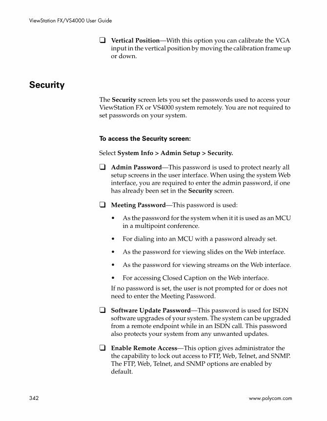
ViewStation FX/VS4000 User Guide
342 www.polycom.com
❑ Vertical Position—With this option you can calibrate the VGA input in the vertical position by moving the calibration frame up or down.
Security
The Security screen lets you set the passwords used to access your ViewStation FX or VS4000 system remotely. You are not required to set passwords on your system.
To access the Security screen:
Select System Info > Admin Setup > Security.
❑ Admin Password—This password is used to protect nearly all setup screens in the user interface. When using the system Web interface, you are required to enter the admin password, if one has already been set in the Security screen.
❑ Meeting Password—This password is used:
• As the password for the system when it it is used as an MCU in a multipoint conference.
• For dialing into an MCU with a password already set.
• As the password for viewing slides on the Web interface.
• As the password for viewing streams on the Web interface.
• For accessing Closed Caption on the Web interface.
If no password is set, the user is not prompted for or does not need to enter the Meeting Password.
❑ Software Update Password—This password is used for ISDN software upgrades of your system. The system can be upgraded from a remote endpoint while in an ISDN call. This password also protects your system from any unwanted updates.
❑ Enable Remote Access—This option gives administrator the the capability to lock out access to FTP, Web, Telnet, and SNMP. The FTP, Web, Telnet, and SNMP options are enabled by default.

Appendix A - Screen Reference
© Polycom, Inc. 2003 343
❑ Enable Remote Access—This option gives administrator the the capability to lock out access to FTP, Web, Telnet, and SNMP. The FTP, Web, Telnet, and SNMP options are enabled by default.
❑ Crypto Resync—This option is only available if a V.35/RS-449/RS-530 network interface is attached to your system.
Crypto Resync Pulse
This screen is specific to a ViewStation FX or VS4000 system with a V.35/RS-449/RS-530 network interface.
To access the Crypto Resync Pulse screen:
1. Select System Info>Admin Setup>Security.
2. In the Security screen, select the Crypto Resync option.
Note
For more configuration information, refer to Enabling Crypto Resync on page 128.
Software and Hardware Screens
To access the Software, RS-232, Hardware Information, Send
Address Book, and Far Site Software Update screens:
Select System Info > Admin Setup > Software/Hardware.

ViewStation FX/VS4000 User Guide
344 www.polycom.com
Software
The Software screen displays the system’s serial number, BOOTUI number, software version, network interface type, ISDN version, and ISDN switch protocols information.
To access the Software screen:
Select System Info > Admin Setup > Software/Hardware > Software.
RS-232
The RS-232 interface allows users to access the system’s ARENA (Application Real-Time-Enabled Network Architecture) Application Programming Interface (API). This API is a set of commands implemented within the shell. The commands are available for advanced users who want to automate some of the control features of the system.
On the RS-232 screen, you can configure the Baud Rate, the RS-232 Mode and the Flow Control options.
To access the RS-232 screen:
Select System Info > Admin Setup > Software/Hardware > RS-232.
Note
For details about the RS-232 options, refer to the Integrators’ Reference Manual for ViewStation EX, ViewStation FX, and VS4000 or to the ViewStation EX, ViewStation FX, and VS4000 ARENA API Programmer’s Guide.
Hardware Information
The Hardware Information screen contains information about the hardware components that make up your system.

Appendix A - Screen Reference
© Polycom, Inc. 2003 345
To access the Hardware Information screen:
Select System Info > Admin Setup > Software/Hardware > Hardware.
If you have a Visual Concert FX connected to your system, information about Visual Concert Software, VCFX In Resolution, and VCFX Out Resolution is displayed on this screen.
Send Address Book
If you are in an ISDN (H.320) call, you also have access to the Send Address Book screen. For more information about the Send Address Book screen, refer to Transferring the Address Book on page 192.
Far Site Software Update
If you are in an ISDN (H.320) call, you also have access to the Far Site Software Update screen. For information about the Far Site Software Update screen, refer to Upgrading Software over ISDN (H.320) on page 59.

ViewStation FX/VS4000 User Guide
346 www.polycom.com

© Polycom, Inc. 2003 347
BInteroperability Information
H.320 Endpoint Interoperability
Table B-1. H.320 Endpoint Interoperability
Manufacturer Model Version
iPower 600 Series 5.0 and 4.0.8
iPower 900 Series 5.0 and 4.0.8
iPower 9000 Series 5.0
Sony PCS6000 4.1
Tandberg 1000 B5.1
Tandberg 2000 B5.1
Tandberg 6000 B5.1
Tandberg 800 B5.1
Tandberg 500 B5.1
VCON Cruiser 4.6
VCONMedia Connect 8000 4.6
VTEL Galaxy 2.2.0.070

348 www.polycom.com
H.323 Endpoint Interoperability
Table B-2 H.323 Endpoint Interoperability
Manufacturer Model Version
Microsoft NetMeeting 2.1
Microsoft NetMeeting 3.0 (no application sharing, file transfer, or whiteboarding)
Microsoft NetMeeting 3.01 (no application sharing, file transfer, or whiteboarding)
iPower 600 Series 5.0 and 4.0.8
iPower 900 Series 5.0 and 4.0.8
iPower 9000 Series 5.0
Sony PCS6000 2.6
Tandberg 1000 B5.1
Tandberg 2500 B5.1
Tandberg 6000 B5.1
Tandberg 800 B5.1
Tandberg 500 B5.1
VCON Cruiser 4.6
VCON Escort 4.6
VCON Media Connect 8000
4.6
VCON Falcon 3.0
VCON Vigo 5.1
VTEL Galaxy 2.2.0.70

Appendix B - Interoperability Information
© Polycom, Inc. 2003 349
MCU H.320 Interoperability
Table B-3. MCU H.320 Interoperability
MCU H.323 Interoperability
Table B-4. MCU H.323 Interoperability
Manufacturer Model Interoperability
Polycom MGC-100 chair control, far-end camera control, T.120, Conference on Demand, People+Content
Lucent Multi-Point Conferencing Unit
chair control
far-end camera control, and T.120 do not work in cascaded calls
Manufacturer Model Version
Polycom MGC-25 5.5
Polycom MGC-50 4.6, 5.0
Polycom MGC-100 4.6, 5.0
Whitepine Meeting Point 5.0
Ezenia MCS 1.2.2
Radvision MCU 2.2.0.9d
Radvision ViaIP 400 MCU 2.2.2651.0
Ezenia Encounter 3000 ECMS 1.01

350 www.polycom.com
Gateway/Gatekeeper/T120 Server Interoperability
Table B-5. Gateway/Gatekeeper/T120 Server Interoperability
Manufacturer Model Version
Polycom MGC-100/gateway 4.5, 5.0
Polycom PathNavigator 1.1, 5.0
Cisco MCM Gatekeeper on the 3640 router
12.1 build 7
Cisco 2515 Gatekeeper
Whitepine Meeting Point Gatekeeper 5.0
Ezenia Gatekeeper 1.2.2
Radvision L2W-323BRI Gateway/Gatekeeper
2.2.3.2.5
Radvision L2W-323PRI Gateway/Gatekeeper
2.2.3.2.5
Radvision MCU Gatekeeper 2.2.1.0.9d
Radvision NGK 200 Gatekeeper 1.0
Radvision T120 Data Collaborator Server 1.07
Radvision ECS/viaIP Gatekeeper 2.0.2.2
Ezenia Encounter 3000 Netgate/Gatekeeper
1.0
Ezenia Encounter 3000 ECMS Gatekeeper
1.01
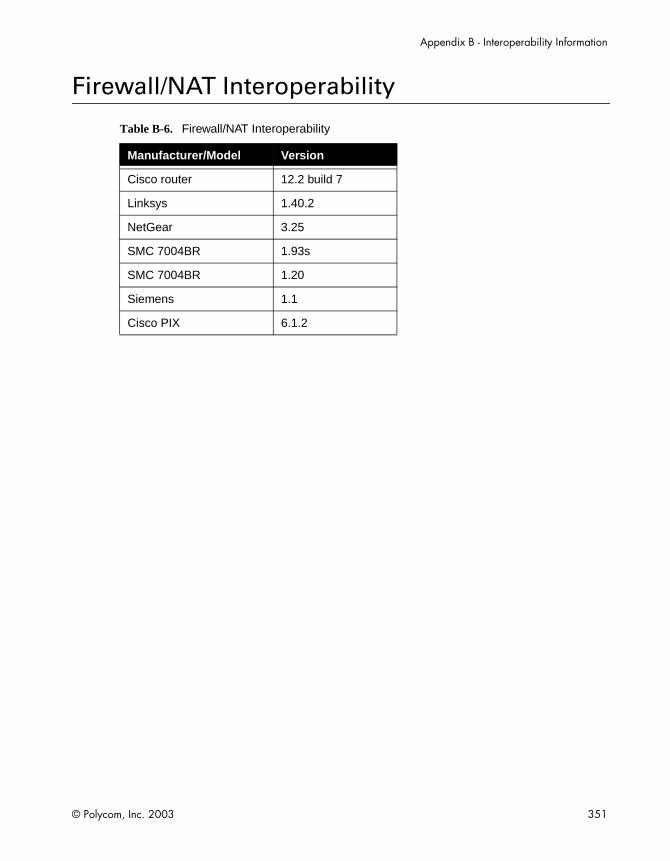
Appendix B - Interoperability Information
© Polycom, Inc. 2003 351
Firewall/NAT Interoperability
Table B-6. Firewall/NAT Interoperability
Manufacturer/Model Version
Cisco router 12.2 build 7
Linksys 1.40.2
NetGear 3.25
SMC 7004BR 1.93s
SMC 7004BR 1.20
Siemens 1.1
Cisco PIX 6.1.2

352 www.polycom.com
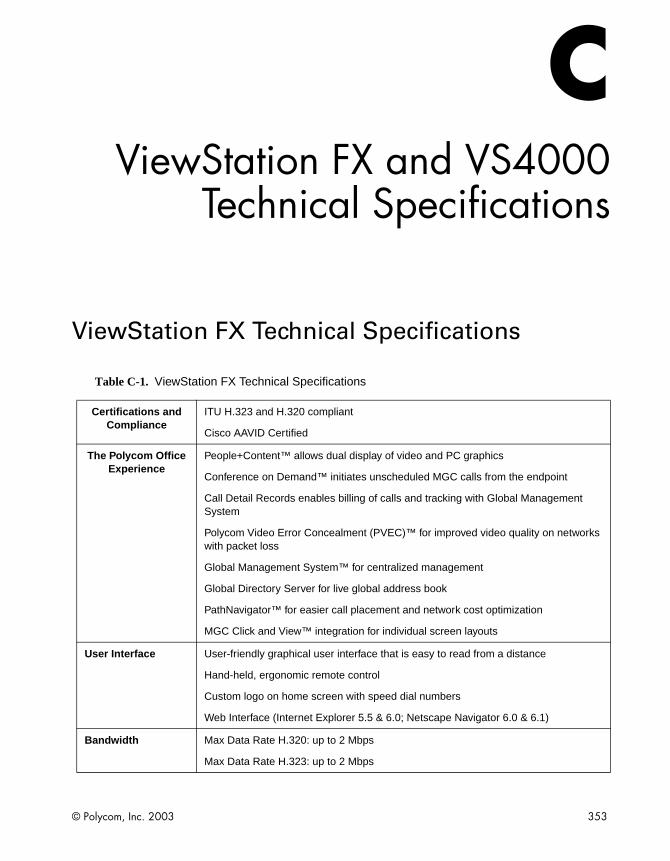
© Polycom, Inc. 2003 353
CViewStation FX and VS4000
Technical Specifications
ViewStation FX Technical Specifications
Table C-1. ViewStation FX Technical Specifications
Certifications and Compliance
ITU H.323 and H.320 compliant
Cisco AAVID Certified
The Polycom Office Experience
People+Content™ allows dual display of video and PC graphics
Conference on Demand™ initiates unscheduled MGC calls from the endpoint
Call Detail Records enables billing of calls and tracking with Global Management System
Polycom Video Error Concealment (PVEC)™ for improved video quality on networks with packet loss
Global Management System™ for centralized management
Global Directory Server for live global address book
PathNavigator™ for easier call placement and network cost optimization
MGC Click and View™ integration for individual screen layouts
User Interface User-friendly graphical user interface that is easy to read from a distance
Hand-held, ergonomic remote control
Custom logo on home screen with speed dial numbers
Web Interface (Internet Explorer 5.5 & 6.0; Netscape Navigator 6.0 & 6.1)
Bandwidth Max Data Rate H.320: up to 2 Mbps
Max Data Rate H.323: up to 2 Mbps
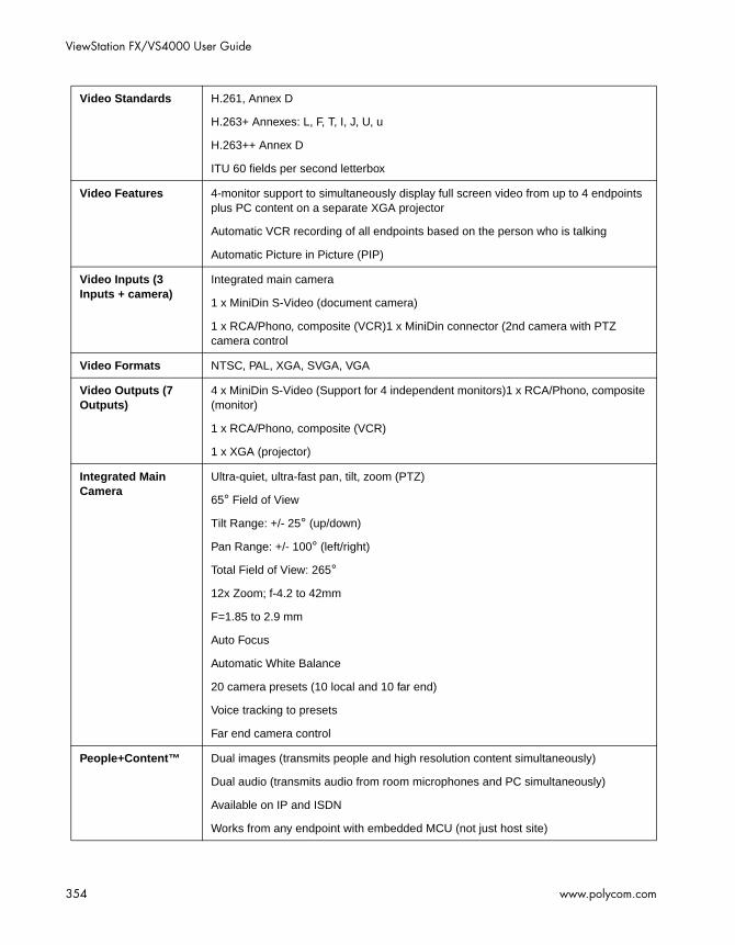
ViewStation FX/VS4000 User Guide
354 www.polycom.com
Video Standards H.261, Annex D
H.263+ Annexes: L, F, T, I, J, U, u
H.263++ Annex D
ITU 60 fields per second letterbox
Video Features 4-monitor support to simultaneously display full screen video from up to 4 endpoints plus PC content on a separate XGA projector
Automatic VCR recording of all endpoints based on the person who is talking
Automatic Picture in Picture (PIP)
Video Inputs (3 Inputs + camera)
Integrated main camera
1 x MiniDin S-Video (document camera)
1 x RCA/Phono, composite (VCR)1 x MiniDin connector (2nd camera with PTZ camera control
Video Formats NTSC, PAL, XGA, SVGA, VGA
Video Outputs (7 Outputs)
4 x MiniDin S-Video (Support for 4 independent monitors)1 x RCA/Phono, composite (monitor)
1 x RCA/Phono, composite (VCR)
1 x XGA (projector)
Integrated Main Camera
Ultra-quiet, ultra-fast pan, tilt, zoom (PTZ)
65° Field of View
Tilt Range: +/- 25° (up/down)
Pan Range: +/- 100° (left/right)
Total Field of View: 265°
12x Zoom; f-4.2 to 42mm
F=1.85 to 2.9 mm
Auto Focus
Automatic White Balance
20 camera presets (10 local and 10 far end)
Voice tracking to presets
Far end camera control
People+Content™ Dual images (transmits people and high resolution content simultaneously)
Dual audio (transmits audio from room microphones and PC simultaneously)
Available on IP and ISDN
Works from any endpoint with embedded MCU (not just host site)

Appendix C - ViewStation FX and VS4000 Technical Specifications
© Polycom, Inc. 2003 355
Live People Video Resolution
4CIF (704 x 576)
CIF (352 x 288)
QCIF (176 x 144)
Live PC Content
Resolution
XGA (1024 x 768)
SVGA (800 x 600)
VGA (640 x 480)
4CIF or CIF for S-Video and composite inputs
Still Image Transfer CIF, 4CIF (H.261 Annex D), 16 CIF High resolution (H.263)
Optional Visual Concert FX
Tabletop device (for audio and video input from PC or Macintosh)
Input: up to 1280x1024, 60 Hz
Output: up to 1024x768, 60 Hz
1 x audio input for PC
1 x video input for PC up to 1280x1024, 60 Hz
1 x video out for projector up to 1024x768, 60 Hz
3 x 10/100 Ethernet hub
Other Content Input Options
pcPresent™ for Microsoft® PowerPoint® presentations from your PC
Polycom SNAP for high resolution graphics capture of PC content
Audio Standards 7 kHz G.722, G.722.1
3.4 kHz with G.711, G.728
Audio Features Instant Adaptation Echo Cancellation
Automatic Gain Control (AGC)- voice activated
Automatic Noise Suppression (ANS)
Built-in tonal speaker test
Audio level meter
Audio mixer
Telephone POTS support
Ability to talk over VCR audio

ViewStation FX/VS4000 User Guide
356 www.polycom.com
Digital Tabletop Microphone
360° voice pick-up, unidirectional performance
Automatic room noise reduction
Gated mixer built into microphone
3 Hyper-cardiod microphones in each microphone pod
Mute button on each microphone pod
Includes 2 microphone pods
Can be mounted to ceiling or walls
Audio Inputs (4 Inputs)
RJ-9 to microphone (daisy chain up to 2 microphone pods)
2 x RCA / Phono line level (VCR)
1 x RCA / Phono line level (Mixer/Auxiliary)
Audio Outputs (4 Outputs)
2 x RCA / Phono line level (main audio)
2 x RCA / Phono line level (VCR)
Frame Rates
(point-to-point)
15 fps - 30 fps
Intelligently selects frame rate for best video performance
TV-quality letterbox 60/50 fields video for NTSC/PAL at 512 kbps and above
Embedded MPPlus Supports mixed combinations of IP, ISDN, and analog telephone calls
Supports IP telephones
Supports normal analog telephones
Automatic IP and ISDN downspeeding
Dial-in and dial-out during multipoint calls
Continuous presence or voice switched
Automatic multipoint presentation modes to automatically switch between presenter and continuous presence modes
Chair control from endpoints or host system on IP
Chair control from endpoints or host system on ISDN
Embedded multipoint for 5 sites (4 IP/ISDN sites + 1 POTS audio)
Cascade up to 14 sites (10 IP/ISDN sites + 4 POTS audio)
Mixed network cascading
Password protection for incoming calls
Supports People+Content dual streams from any endpoint (not just host site)

Appendix C - ViewStation FX and VS4000 Technical Specifications
© Polycom, Inc. 2003 357
Network Features Automatic H.320/H.323 calling
Downspeeding over IP and ISDN
OneDial intelligent call management attempts call on preferred network (IP or ISDN) and automatically rolls over to secondary network if needed
Maximum call length timer
Auto-SPID detection and configuration
NATO standard KG-194/KIV-7 encryptor support with on-screen and address book dialing
Software upgradable Inverse Multiplexer (IMUX)
Dial ISDN lines separately or simultaneously
Quality of Service and Experience - iPriority
Polycom Video Error Concealment (PVEC) for concealing packet loss
IP Precedence (ToS)
DiffServ DHCP (CoS)
Dynamic bandwidth allocation
Proactive network monitoring
Packet and jitter control
Network Address Translation (NAT) support
Automatic NAT discovery
Asymmetric speed control
Fixed TCP/UDP port firewall support
Lip synchronization
Echo cancellation
Echo suppression
Auto gatekeeper discovery
Automatic gateway dialing profiles
Specify outbound call routing for gateway/ISDN
Closed captioning and text chat support both in and out of calls
Keypad audio confirmation makes dialing easy

ViewStation FX/VS4000 User Guide
358 www.polycom.com
Security Features Independently tested for endpoint security
Enhanced integration for independently certified corporate and classified encryption devices
Secure password authentication
Unique factory default passwords
Administrator password
Dial-in meeting password
Do not disturb meeting feature for point to point
Do not disturb meeting feature for multipoint calls
Select which menu screens to password protect
SNMP security alerts for failed and successful password authentication attempts
Option to disable remote interfaces (FTP, SNMP, Telnet, HTTP, streaming)
Option to disable mixed protocol multipoint calls
Network Interfaces Supported
2 independent 10/100 Ethernet ports for IP (LAN, DSL, cable modem)
Integrated Ethernet switch
1 x POTS for voice
Optional Quad BRI (Basic Rate Interface)
Optional PRI (Primary Rate Interface) T1/ E1
Optional 2 port Serial Module (V.35/RS-530/RS-449 with RS-366 dialing)
Optional wireless LAN support via Ethernet port
Ethernet Connectivity
TCP/IP, HTTP, DNS, WINS, SNMP, DHCP, ARP, FTP, Telnet
T.120 interface for Microsoft® NetMeeting
Internal live video unicast or multicast stream to Apple® Quicktime, Cisco IP/TV
Directory Services 1000+ number local directory
10,000+ number global directory
Unlimited multipoint entries
Live address book with Polycom Global Address Book automatically and quickly updates directory with address changes or new endpoints
Live address book with Polycom Global Address Book automatically and quickly removes endpoints from directory if they are turned off
Polycom Global Address Book integrates with Active Directory / LDAP
Automatic ISDN localization of calls
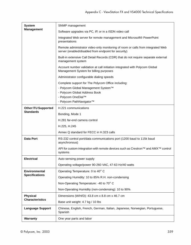
Appendix C - ViewStation FX and VS4000 Technical Specifications
© Polycom, Inc. 2003 359
System Management
SNMP management
Software upgrades via PC, IP, or in a ISDN video call
Integrated Web server for remote management and Microsoft® PowerPoint presentations
Remote administrator video-only monitoring of room or calls from integrated Web server (enabled/disabled from endpoint for security)
Built-in extensive Call Detail Records (CDR) that do not require separate external management system
Account number validation at call initiation integrated with Polycom Global Management System for billing purposes
Administrator configurable dialing speeds
Complete support for The Polycom Office including:
- Polycom Global Management System™
- Polycom Global Address Book
- Polycom OneDial™
- Polycom PathNavigator™
Other ITU Supported Standards
H.221 communications
Bonding, Mode 1
H.281 far-end camera control
H.225, H.245
Annex Q standard for FECC in H.323 calls
Data Port RS-232 control port/data communications port (1200 baud to 115k baud asynchronous)
API for custom integration with remote devices such as Crestron™ and AMX™ control systems
Electrical Auto-sensing power supply
Operating voltage/power 90-260 VAC, 47-63 Hz/40 watts
Environmental Specifications
Operating Temperature: 0 to 40° C
Operating Humidity: 10 to 85% R.H. non-condensing
Non-Operating Temperature: -40 to 70° C
Non-Operating Humidity (non-condensing): 10 to 90%
Physical Characteristics
Dimensions (W/H/D): 43.8 cm x 8.8 cm x 46.7 cm
Base unit weight: 4.7 kg / 10 lbs
Language Support Chinese, English, French, German, Italian, Japanese, Norwegian, Portuguese, Spanish
Warranty One year parts and labor

ViewStation FX/VS4000 User Guide
360 www.polycom.com
VS4000 Technical Specifications
Table C-2. VS4000 Technical Specifications
Certifications and Compliance
ITU H.323 and H.320 compliant
Cisco AAVID Certified
The Polycom Office Experience
People+Content™ allows dual display of video and PC graphics
Conference on Demand™ initiates unscheduled MGC calls from the endpoint
Call Detail Records enables billing of calls and tracking with Global Management System™
Polycom Video Error Concealment (PVEC)™ for improved video quality on networks with packet loss
Global Management System™ for centralized management
Global Directory Server for live global address book
PathNavigator™ for easier call placement and network cost optimization
MGC Click & View™ integration for individual screen layouts
User Interface User-friendly graphical user interface that is easy to read from a distance
Hand-held, ergonomic remote control
Custom logo on home screen with speed dial numbers
Web Interface (Internet Explorer 5.5 & 6.0; Netscape Navigator 6.0 & 6.1)
Bandwidth Max Data Rate H.320: up to 2 Mbps
Max Data Rate H.323: up to 2 Mbps
Video Standards H.261, Annex D
H.263+ Annexes: L, F, T, I, J, U, u
H.263++ Annex D
ITU 60 fields per second letterbox
Video Features 4-monitor support to simultaneously display full screen video from up to 4 endpoints plus PC content on a separate XGA projector
Automatic VCR recording of all endpoints based on the person who is talking
Automatic Picture in Picture (PIP)

Appendix C - ViewStation FX and VS4000 Technical Specifications
© Polycom, Inc. 2003 361
Video Inputs (7 Inputs)
1 x MiniDin S-video (main camera with PTZ control)
1 x MiniDin S-Video (document camera)
1 x MiniDin S-video (second camera with PTZ control)
1 x RCA/Phono, composite (main camera)
1 x RCA/Phono, composite (document camera)
1 x RCA/Phono, composite (VCR)
1 x RCA/Phono, composite (second camera with PTZ control)
Video Formats NTSC, PAL, XGA, SVGA, VGA
Video Outputs (10 Outputs)
4 x MiniDin S-Video (Support for 4 independent monitors)
4 x RCA/Phono, composite (Support for 4 independent monitors)
1 x RCA/Phono, composite (VCR)
1 x XGA (projector)
Option Polycom PowerCam External Camera
Ultra-quiet, ultra-fast pan, tilt, zoom (PTZ)
65° field of View
Tilt Range: +/- 25° (up/down)
Pan Range: +/- 100° (left/right)
Total Field of View: 265°
12x Zoom; f-4.2 to 42mm
F=1.85 to 2.9 mm
Auto Focus
Automatic White Balance
20 camera presets (10 local and 10 far end)
Far end camera control
People+Content™ Dual images (transmits people and high resolution content simultaneously)
Dual audio (transmits audio from room microphones and PC simultaneously)
Available on IP and ISDN
Works from any endpoint with embedded MCU (not just host site)
Live People Video Resolution
4CIF (704 x 576)
CIF (352 x 288)
QCIF (176 x 144)

ViewStation FX/VS4000 User Guide
362 www.polycom.com
Live PC Content
Resolution
XGA (1024 x 768)
SVGA (800 x 600)
VGA (640 x 480)
4CIF or CIF for S-Video and composite inputs
Still Image Transfer CIF, 4CIF (H.261 Annex D), 16 CIF high resolution (H.263)
Optional Visual™ Concert FX
Tabletop device (for audio and video input from PC or Macintosh)
Input: up to 1280x1024, 60 Hz
Output: up to 1024x768, 60 Hz
1 x audio input for PC
1 x video input for PC up to 1280x1024, 60 Hz
1 x video out for projector up to 1024x768, 60 Hz
3 x 10/100 Ethernet hub
Other Content Input Options
pcPresent™ for Microsoft® PowerPoint® presentations from your PC
Polycom SNAP for high resolution graphics capture of PC content
Audio Standards 7 kHz G.722, G.722.1
3.4 kHz with G.711, G.728
Audio Features Instant Adaptation Echo Cancellation
Automatic Gain Control (AGC)- voice activated
Automatic Noise Suppression (ANS)
Built-in tonal speaker test
Audio level meter
Audio mixer
Telephone POTS support
Ability to talk over VCR audio
Digital Tabletop Microphone
360° voice pick-up, unidirectional performance
Automatic room noise reduction
Gated mixer built into microphone
3 hyper-cardiod microphones in each microphone pod
Mute button on each microphone pod
Includes 2 microphone pods
Can be mounted to ceiling or walls

Appendix C - ViewStation FX and VS4000 Technical Specifications
© Polycom, Inc. 2003 363
Audio Inputs (4 Inputs)
RJ-9 to microphone (daisy chain up to 2 microphone pods)
2 x RCA / Phono line level (VCR)
1 x RCA / Phono line level (Mixer/Auxiliary)
Audio Outputs (4 Outputs)
2 x RCA / Phono line level (main audio)
2 x RCA / Phono line level (VCR)
Frame Rates
(point-to-point)
15 fps - 30 fps
Intelligently selects frame rate for best video performance
Near TV-quality letterbox 60/50 fields video for NTSC/PAL at 512 kbps and above
Embedded MPPlus Supports mixed combinations of IP, ISDN, and analog telephone calls
Supports IP telephones
Supports normal analog telephones
Automatic IP and ISDN downspeeding
Dial-in and dial-out during multipoint calls
Continuous presence or voice switched
Automatic multipoint presentation modes to automatically switch between presenter and continuous presence modes
Chair control from endpoints or host system on IP
Chair control from endpoints or host system on ISDN
Embedded multipoint for 5 sites (4 IP/ISDN sites + 1 POTS audio)
Cascade up to 14 sites (10 IP/ISDN sites + 4 POTS audio)
Mixed network cascading
Password protection for incoming calls
Supports People+Content dual streams from any endpoint (not just host site)
Network Features Automatic H.320/H.323 calling
Downspeeding over IP and ISDN
OneDial intelligent call management attempts call on preferred network (IP or ISDN) and automatically rolls over to secondary network if needed
Maximum call length timer
Auto-SPID detection and configuration
NATO standard KG-194/KIV-7 encryptor support with on-screen and address book dialing
Software upgradable Inverse Multiplexer (IMUX)
Dial ISDN lines separately or simultaneously

ViewStation FX/VS4000 User Guide
364 www.polycom.com
Quality of Service and Experience - iPriority™
Polycom Video Erro r Concealment (PVEC) for concealing packet loss
IP Precedence (ToS)
DiffServ DHCP (CoS)
Dynamic bandwidth allocation
Proactive network monitoring
Packet and jitter control
Network Address Translation (NAT) support
Automatic NAT discovery
Asymmetric speed control
Fixed TCP/UDP port firewall support
Lip synchronization
Echo cancellation
Echo suppression
Auto gatekeeper discovery
Automatic gateway dialing profiles
Specify outbound call routing for gateway/ISDN
Closed captioning and text chat support both in and out of calls
Keypad audio confirmation makes dialing easy
Security Features Independently tested for endpoint security
Enhanced integration for independently certified corporate and classified encryption devices
Secure password authentication
Unique factory default passwords
Administrator password
Dial-in meeting password
Do not disturb meeting feature for point to point
Do not disturb meeting feature for multipoint calls
Select which menu screens to password protect
SNMP security alerts for failed and successful password authentication attempts
Option to disable remote interfaces (FTP, SNMP, Telnet, HTTP, streaming)
Option to disable mixed protocol multipoint calls
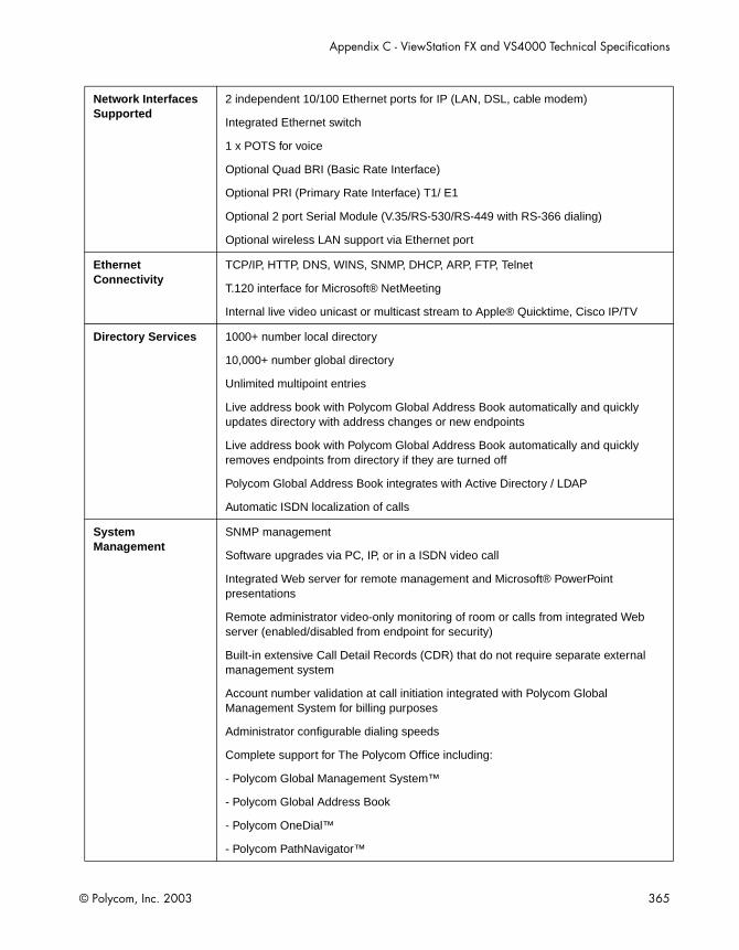
Appendix C - ViewStation FX and VS4000 Technical Specifications
© Polycom, Inc. 2003 365
Network Interfaces Supported
2 independent 10/100 Ethernet ports for IP (LAN, DSL, cable modem)
Integrated Ethernet switch
1 x POTS for voice
Optional Quad BRI (Basic Rate Interface)
Optional PRI (Primary Rate Interface) T1/ E1
Optional 2 port Serial Module (V.35/RS-530/RS-449 with RS-366 dialing)
Optional wireless LAN support via Ethernet port
Ethernet Connectivity
TCP/IP, HTTP, DNS, WINS, SNMP, DHCP, ARP, FTP, Telnet
T.120 interface for Microsoft® NetMeeting
Internal live video unicast or multicast stream to Apple® Quicktime, Cisco IP/TV
Directory Services 1000+ number local directory
10,000+ number global directory
Unlimited multipoint entries
Live address book with Polycom Global Address Book automatically and quickly updates directory with address changes or new endpoints
Live address book with Polycom Global Address Book automatically and quickly removes endpoints from directory if they are turned off
Polycom Global Address Book integrates with Active Directory / LDAP
Automatic ISDN localization of calls
System Management
SNMP management
Software upgrades via PC, IP, or in a ISDN video call
Integrated Web server for remote management and Microsoft® PowerPoint presentations
Remote administrator video-only monitoring of room or calls from integrated Web server (enabled/disabled from endpoint for security)
Built-in extensive Call Detail Records (CDR) that do not require separate external management system
Account number validation at call initiation integrated with Polycom Global Management System for billing purposes
Administrator configurable dialing speeds
Complete support for The Polycom Office including:
- Polycom Global Management System™
- Polycom Global Address Book
- Polycom OneDial™
- Polycom PathNavigator™

ViewStation FX/VS4000 User Guide
366 www.polycom.com
Other ITU Supported Standards
H.221 communications
Bonding, Mode 1
H.281 far-end camera control
H.225, H.245
Annex Q standard for FECC in H.323 calls
Data Port RS-232 control port/data communications port (1200 baud to 115k baud asynchronous)
API for custom integration with remote devices such as Crestron™ and AMX™ control systems
Electrical Auto-sensing power supply
Operating voltage/power 90-260 VAC, 47-63 Hz/40 watts
Environmental Specifications
Operating Temperature: 0 to 40° C
Operating Humidity: 10 to 85% R.H. non-condensing
Non-Operating Temperature: -40 to 70° C
Non-Operating Humidity (non-condensing): 10 to 90%
Physical Characteristics
Dimensions (W/H/D): 43.8 cm x 8.8 cm x 46.7 cm
Base unit weight: 4.7 kg / 10 lbs
Language Support Chinese, English, French, German, Italian, Japanese, Norwegian, Portuguese, Spanish
Warranty One year parts and labor

© Polycom, Inc. 2003 367
DSecurity Features
This appendix contains ViewStation FX and VS4000 reference information on security-related screens and features.
The following topics are included in this chapter.
Topic Description Page
Security Screens
This section describes the Admin and Meeting Password and the Security screens.
368
PMAC Security Features
The Polycom Management Access Control Wizard (PMAC) lets you password protect on screens on a menu-by-menu basis with a special access password.
369
Security Features and Enhancements
This section describes the various security features and enhancements such as Digest and Adtran 512.
372

ViewStation FX/VS4000 User Guide
368 www.polycom.com
Security Screens
This section provides information about the screen and the screen.
The screen is part of the out-of-box configuration sequence. It features unique factory default passwords: it contains an initial administrator password, which is your system’s serial number, and a meeting password that is randomly generated. For additional information, refer to Setting the Administrator and Meeting Passwords in chapter 3.
The screen lets you set the passwords used to access your ViewStation FX or VS4000 system remotely. You are not required to set passwords on your system.
Select
❑ —This password is used to protect nearly all setup screens in the user interface. When using the system Web interface, you are required to enter the admin password, if one has already been set in the screen.
❑ —This password is used:
As the password for the system when it is used as an MCU in a multipoint conference.
For dialing into an MCU with a password already set.
As the password for viewing slides on the Web interface.
As the password for viewing streams on the Web interface.

Appendix D - Security Features
© Polycom, Inc. 2003 369
For accessing Closed Caption on the Web interface.
If no password is set, the user is not prompted for or does not need to enter the Meeting Password.
❑ —This password is used for ISDN software upgrades of your system. The system can be upgraded from a remote endpoint while in an ISDN call. This password also protects your system from any unwanted updates.
❑ —This option gives administrator the the capability to lock out access to FTP, Web, Telnet, and SNMP. The FTP, Web, Telnet, and SNMP options are enabled by default.
❑ —This option is only available if a V.35/RS-449/RS-530 network interface is attached to your system.
PMAC Security Features
The Polycom Management Access Control Wizard (PMAC) allows you to select which menu screens to password protect on a menu-by-menu basis with a special access password. PMAC offers other features which are not covered in this section. They are described in chapter 7.
This application is available on your software CD and can also be downloaded from the Polycom Website ( Go to http://www.polycom.com/resource_center/. Then select Software Downloads.)
This section contains information about:
Creating the Management Password (special-access password)
Password-Protecting Individual Screens

ViewStation FX/VS4000 User Guide
370 www.polycom.com
The Management Password is different from the Admin Password. The Admin Password allows access to the Admin Setup screens. The Management Password allows the administrator to password-protect (lock) specific screens. In other words, the Admin Password allows a user to access the admin section, but the Management Password is needed to access a specific screen.
Launch the utility
Enter the and the of the system.
Select the tab.
Enter the Management Password. Re-enter the Management Password.
Clisk the button to install the settings.
When you try to access a screen that is password protected, you are prompted to enter the Management Password. If the wrong password is entered, you are not allowed to access the screen.
The Management Password overrides the Admin Password. For example, if you have both an Admin Password and a Management Password, use the Management Password to log into the system from the PMAC utility.
Table D-1. Password Usage with PMAC
Admin PasswordManagement Password
Password to Use When Using PMAC
Yes No Admin
Yes Yes Management
No Yes Management
No No No password

Appendix D - Security Features
© Polycom, Inc. 2003 371
In order to password-protect screens, a Management Password must be created first (see preceding section). Then, from the
tab, you can specify which screens to lock.
Launch the utility
Enter the and of your system.
Select the tab.
Double- click an item in the left column ( ). While holding the key on the keyboard, single-click as many items in that column.
Press the button to move items from the left to the right column. Items in the right column (
) are password-protected screens.
Select the button to install the settings.
Double-click an item in the right column of the screen. While holding the key on the keyboard, single-click as many items in that column.
Press the button to move items from the right to the left column.
Select the button to install the settings.

ViewStation FX/VS4000 User Guide
372 www.polycom.com
Security Features and Enhancements
When you are presenting launching a presentation from a PC, you can specify a password for that presentation. Users must enter the specified password in order to load the presentation. If you wish to view the presentation, you must enter the meeting password.
Digest authentication is used for sending passwords to the Web server for enhanced security.
Basic authentication, which is the current form of authentication, uses a very simple algorithm to encode the user name and password. For example, people "snooping" on the packets sent to your system can capture these packets and decode the admin password in five minutes. Digest authentication is a much more complicated algorithm than basic authentication. Even if people manage to capture one of the packets that contain Digest authentication, they cannot decipher the admin password .
Polycom has enabled enhanced integration with the Adtran 512 ISU IMUX including RS-366 dialing from the system’s user interface (V.35). This allows end-users to dial calls from the system’s address book or dialing screen instead of having to manually enter in the number on the Adtran keypad. This is especially useful when used with KIV or KG encryption devices that require an external IMUX such as the Adtran 512 ISU to dial calls.

Appendix D - Security Features
© Polycom, Inc. 2003 373
The option (Admin Setup>Video Network>Call Preferences) allows the administrator to disable the ability to place or received mixed multipoint calls for security reasons.
This option is only accessible if the or ISDN Video Calls and LAN/Internet Calls options are both enabled on the Call Preferences screen.
There is a 30-second timeout when logging into FTP and Telnet. This is intended to make the connection time out to free it in case the login is unsuccessful.

ViewStation FX/VS4000 User Guide
374 www.polycom.com

© Polycom, Inc. 2003 375
Safety and Legal NoticesImportant Safeguards
Read and understand the following instructions before using the system: • Close supervision is necessary when the system is used by or near children. Do not leave
unattended while in use.• Only use electrical extension cords with a current rating at least equal to that of the system.• Always disconnect the system from power before cleaning and servicing and when not in use.• Do not spray liquids directly onto the system when cleaning. Always apply the liquid first to a
static free cloth. • Do not immerse the system in any liquid or place any liquids on it.• Do not disassemble this system (except as instructed in the manufacturer's instructions). To
reduce the risk of shock and to maintain the warranty on the system, a qualified technician must perform service or repair work.
• Connect this appliance to a grounded outlet.• In case of lightning storms, disconnect the telephone line cord from the system, and only
connect the system to surge protected power outlets.• The socket outlet to which this apparatus is connected must be installed near the equipment
and must always be readily accessible.• Keep ventilation openings free of any obstructions.• SAVE THESE INSTRUCTIONS.
License Restrictions
THE SOFTWARE PROGRAMS CONTAINED OR DESCRIBED HEREIN ARE CONFIDENTIAL INFORMATION AND PROPRIETARY PRODUCTS OF POLYCOM OR ITS LICENSORS.
Buyer shall not sublicense or otherwise distribute any of the Subject Programs except to End Users and/or resellers who have entered into a Sublicense Agreement. For purposes of this Agreement a “Sublicense Agreement” shall mean a written license agreement between the Buyer and its purchaser, or, in the case of any sale by Buyer to a reseller, between such reseller and the End User, that is either 1) signed by the End User or 2) included with the Documentation, in such a manner that the End User reasonably indicates its acceptance of the Sublicense Agreement by turning on and using the Computer Equipment. Polycom shall include so-called “break the seal software licenses” with the Documentation, and Buyer shall not remove or alter any such Sublicense Agreements or any notifications or warning stickers relating thereto. Buyer shall not waive, amend, or otherwise modify any Sublicense Agreement without Polycom’s prior consent.
Title to all Subject Programs shall at all times remain and vest solely with Polycom and its licensors. Buyer acknowledges Polycom, Inc.’s claim that the Subject Programs are its trade secret and confidential property, and shall treat them as such. Buyer will not attempt to disassemble, decompile, reverse-engineer or otherwise endeavor to discover or disclose the methods and concepts embodied in the Subject Programs. Except as expressly allowed under this Agreement, the Buyer shall not copy, modify, transcribe, store, translate, sell, lease, or otherwise transfer or distribute any of the Subject Programs in whole or in part, without prior authorization, in writing, from Polycom. Buyer shall not remove or destroy any copyright, patent, trademark or other proprietary mark or notice on Computer Equipment, and shall reproduce any such marks on any copies of Subject Programs that it makes hereunder.
You shall not and shall not allow any third party to 1) decompile, disassemble, or otherwise reverse-engineer or attempt to reconstruct or discover any source code or underlying ideas or algorithms of the software by any means whatsoever or 2) remove any product.

ViewStation FX/VS4000 User Guide
376 www.polycom.com
Warranty
Polycom, Inc. warrants its products to be free of defects in materials and factory workmanship for a period of twelve (12) months from date of purchase. This warranty does not apply to damage to products resulting from accident, misuse, service or modification by anyone other than a Polycom, Inc. authorized service facility/dealer. The warranty is limited to the original purchaser and is not transferable. Any liability of Polycom, Inc. or its suppliers with respect to the product or the performance thereof under any warranty, negligence, strict liability or other theory will be limited exclusively to product repair or replacement as provided above. Except for the foregoing, the product is provided “as is” without warranty of any kind including without limitation, any warranty of merchantability or fitness for a particular purpose. The entire risk of the quality and performance of the software programs contained in the system is with you.
Limitation of Remedies and Damages
Polycom, Inc., its agents, employees, suppliers, dealers and other authorized representatives shall not be responsible or liable with respect to the product or any other subject matter related thereto under any contract, negligence, strict liability or other theory for any indirect, incidental, or consequential damages, including, but not limited to loss of information, business, or profits.
The law of certain states or nations does not permit limitation or exclusion of implied warranties and consequential damages, so the above limitations, disclaimers, or exclusion may not apply to you. This warranty gives you special legal rights. You may also have other rights that vary by state and nation.
Warning
This is a Class A product. In a domestic environment, this product may cause radio interference in which case the user may be required to take adequate measures.
USA and Canadian Regulatory Notices
FCC Notice
Part 15 FCC Rules
This device complies with part 15 of the FCC rules. Operation is subject to the following two conditions:
1) This device may not cause harmful interference, and 2) this device must accept any interference received, including interference that may cause undesired operation.
Class A Digital Device
This equipment has been tested and found to comply with the limits for a Class A digital device, pursuant to Part 15 of the FCC Rules. These limits are designed to provide reasonable protection against harmful interference when the equipment is operated in a commercial environment. This equipment generates, uses, and can radiate radio frequency energy and, if not installed and used in accordance with the instruction manual, may cause harmful interference to radio communications. Operation of this equipment in a residential area is likely to cause harmful interference in which case the user will be required to correct the interference at his own expense.
In accordance with Part 15 of the FCC rules, the user is cautioned that any changes or modifications not expressly approved by Polycom Inc. could void the user's authority to operate this equipment.
Safety and Legal Notices
© Polycom, Inc. 2003 377
Part 68 FCC Rules
This equipment complies with Part 68 of the FCC rules. On the label of this equipment is a label that contains, among other information, the FCC registration number and ringer equivalence number (REN) for this equipment. If requested, this information must be provided to the telephone company.
This equipment may not be used on a coin service or party line.
If you experience trouble with your ViewStation EX/FX/VS4000, disconnect it from the telephone line to determine if the registered equipment is malfunctioning. For repair or warranty information, please contact Polycom Inc. at 1-888-248-4143 or 4750 Willow Road, Pleasanton, CA 94588-2708, USA. Contact information may also be found at http://www.polycom.com/. If the system is causing harm to the network, the telephone company may request that you disconnect it until the problem is corrected.
If your ViewStation EX/FX/VS4000 causes harm to the telephone network, the telephone company will notify you in advance that temporary discontinuance of service may be required. However, if advance notice is not practical, you will be notified as soon as possible. You will be advised of your right to file a complaint with the FCC if you believe it is necessary.
Your telephone company may make changes in its facilities, equipment, operations, or procedures that could affect the operation of your equipment. If they do, you will be given advance notice so that you may make any changes necessary to maintain uninterrupted service.
The REN is useful to determine the quantity of devices that may be connected to the telephone line. Excessive RENs on the telephone line may result in the devices not ringing in response to an incoming call. In most, but not all areas, the sum of RENs of all devices that may be connected to a line, is determined by the total RENs, contact the local telephone company.
FCC compliant telephone cords and modular plugs are provided with this equipment. This equipment is designed to be connected to the telephone network or premises’ wiring using a compatible modular jack, which is Part 68 compliant. See installation instructions for details.
WHEN PROGRAMMING EMERGENCY NUMBERS AND/OR MAKING TEST CALLS TO EMERGENCY NUMBERS:
1) Remain on the line and briefly explain to the dispatcher the reason for the call.
2) Perform such activities in the off-peak hours, such as early morning or late evening.
Industry Canada (IC)
This class A digital apparatus complies with Canadian ICES-003.
Cet appareil numerique de la classe A est conforme à la norme NMB-003 du Canada.
The Industry Canada label identifies certified equipment. This certification means that the equipment meets telecommunications network protective, operational and safety requirements as prescribed in the appropriate Terminal Equipment Technical Requirements document(s). The Department does not guarantee the equipment will operate to the user's satisfaction.
Before installing this equipment, users should ensure that it is permissible to be connected to the facilities of the local telecommunications company. The equipment must also be installed using an acceptable method of connection. The customer should be aware that compliance with the above conditions may not prevent degradation of service in some situations. Repairs to certified equipment should be coordinated by a representative designated by the supplier. Any repairs or alterations made by the user to this equipment, or equipment malfunctions, may give the telecommunications company cause to request the user to disconnect the equipment.
Users should ensure for their own protection that the electrical ground connections of the power utility, telephone lines and internal metallic water pipe system, if present, are connected together. This precaution may be particularly important in rural areas.
Caution: Users should not attempt to make such connections themselves, but should contact the appropriate electric inspection authority, or electrician, as appropriate.

ViewStation FX/VS4000 User Guide
378 www.polycom.com
The Ringer Equivalence Number (REN) assigned to each relevant terminal device provides an indication of the maximum number of terminals allowed to be connected to a telephone interface. The termination on an interface may consist of any combination of devices subject only to the requirement that the sum of the RENs of all the devices does not exceed 5.
The REN of this equipment is either marked on the unit or included in the new style USA FCC registration number. In the case that the REN is included in the FCC number, the user should use the following key to determine the value: • The FCC number is formatted as US:AAAEQ#TXXX.• # is the Ringer Equivalence Number without a decimal point (e.g. REN of 1.0 will be shown
as 10, REN of 0.3 will be shown as 03). In the case of a Z ringer, ZZ shall appear. In the case of approved equipment without a network interface or equipment not to be connected to circuits with analog ringing supplied, NA shall appear.
EEA Regulatory Notices
CE Mark
This ViewStation EX/FX/VS4000 has been marked with the CE mark. This mark indicates compliance with EEC Directives 1999/5/EC. A full copy of the Declaration of Conformity can be obtained from Polycom Ltd., 270 Bath Road, Slough UK SL1 4DX.
Declaration of Conformity:
Hereby, Polycom Ltd. declares that this ViewStation EX/FX/VS4000 is in compliance with the essential requirements and other relevant provisions of Directive 1999/5/EC.
Konformitetserklæring:
Hermed erklærer Polycom Ltd., at indestående ViewStation EX/FX/VS4000 er i overensstemmelse med de grundlæggende krav og de relevante punkter i direktiv 1999/5/EF.
Konformitätserklärung:
Hiermit erklärt Polycom Ltd., dass der ViewStation EX/FX/VS4000 die grundlegenden Anforderungen und sonstige maßgebliche Bestimmungen der Richtlinie 1999/5/EG erfüllt.
Vaatimustenmukaisuusvakuutus:
Polycom Ltd. vakuuttaa täten, että ViewStation EX/FX/VS4000 on direktiivin 1999/5/EC keskeisten vaatimusten ja sen muiden tätä koskevien säännösten mukainen.
Déclaration de conformité:
Par la présente, Polycom Ltd. déclare que ce ViewStation EX/FX/VS4000 est conforme aux conditions essentielles et à toute autre modalité pertinente de la Directive 1999/5/CE.

Safety and Legal Notices
© Polycom, Inc. 2003 379
Dichiarazione di conformità:
Con la presente Polycom Ltd. dichiara che il ViewStation EX/FX/VS4000 soddisfa i requisiti essenziali e le altre disposizioni pertinenti della direttiva 1999/5/CE.
Verklaring van overeenstemming:
Hierbij verklaart Polycom Ltd. dat diens ViewStation EX/FX/VS4000 voldoet aan de basisvereisten en andere relevante voorwaarden van EG-richtlijn 1999/5/EG.
Declaração de Conformidade:
Através da presente, a Polycom Ltd. declara que este ViewStation EX/FX/VS4000 se encontra em conformidade com os requisitos essenciais e outras disposições relevantes da Directiva 1999/5/CE.
Declaración de conformidad:
Por la presente declaración, Polycom Ltd. declara que este ViewStation EX/FX/VS4000 cumple los requisitos esenciales y otras cláusulas importantes de la directiva 1999/5/CE.
Överensstämmelseförklaring:
Polycom Ltd. förklarar härmed att denna ViewStation EX/FX/VS4000 överensstämmer med de väsentliga kraven och övriga relevanta stadganden i direktiv 1999/5/EG.
WARNING
This is a Class A product. In a domestic environment this product may cause radio interference in which case the user may be required to take adequate measures.
Australia
Mains Powered POTS Voice Telephony Without Emergency 000 Dialing
Warning: This equipment will be inoperable when mains power fails.
Japan

ViewStation FX/VS4000 User Guide
380 www.polycom.com
Underwriters Laboratories Statement
The system is intended to be powered only by the supplied power supply unit.
Special Safety Instructions
Follow existing safety instructions and observe all safeguards as directed.
Installation Instructions
Installation must be performed in accordance with all relevant national wiring rules.

© Polycom, Inc. 2003 381
Numerics4CIF resolution, 33860 fields/sec at>=512Kbps, 335
AAddress Book
access, 189adding an entry, 190creating a meeting entry, 218deleting an entry, 192editing an existing entry, 191erasing entries, 314multipoint entries, 194placing a call from, 181placing a call, 181send, 345transferring, 192
Admin Password, 342, 368Admin Setup screen reference, 319Admin Setup Web icons, 281Administrator Password, 95Advanced configuration
BRI, 141Gateway and Gatekeeper, 116Global Address Book, 148IP, 111LAN, 103PRI, 129V.35/RS-449/RS-530, 121
Advanced DialingBRI, 145PRI, 139V.35/RS-449/RS-530, 83, 127
Advanced Network Statistics, 309Advanced PRI Setup, 136Allow Address Book Changes, 321
Allow Remote Monitoring, 161, 317Allow System to be a DHCP Server, 58Allow User Setup, 283, 321Analog call
adding a video call to, 188adding to a video call, 187disconnecting, 187placing, 186
Annex D information, 266Answering a call
manually, 183, 184Audio
advanced troubleshooting, 293audio error concealment, 139, 333basic troubleshooting, 30diagnostics, 309protocols, 333test levels, 313
Audio Meter, 313Audio Quality Preference
PRI, 138Audio Quality Preference (BRI), 144Auto Answer Multipoint, 228, 235, 236, 316Auto Answer Point to Point, 315, 320Auto H.323 Dialing, 77, 112Auto-Detect SPIDs (BRI), 90, 143
BBacklight Compensation, 317BRI
advanced configuration, 141Advanced Dialing, 145Audio Quality Preference configura-
tion, 144Auto-Detect SPIDs, 90automatic Quad BRI software update,
49
Index

382 www.polycom.com
ViewStation FX/VS4000 User Guide
configuration screen reference, 325Dialing Speeds, 146IMUX configuration, 325IMUX, 49initial configuration, 89ISDN Video Numbers, 90, 141network interface installation, 47SPIDs, 143Video Network configuration, 147
Broadcast Mode (V.35/RS-449/RS-530), 82,123
CCables
Ascend HD-44M to HD-44M(V.35/RS-449/RS-530), 35, 43
HD-44M to DB-25M/RS-366 and M34Winchester (V.35/RS-449), 35,43
HD-44M to RS-449/S-422 Y(V.35/RS-449/RS-530), 35, 43
PRI cable adapter kit, 46supplied for ViewStation FX, 22supplied for VS4000, 23V.35/RS-449/RS-530 cable adapter kit,
44Call Detail Report 286Call Hangup Choices, 180Call Preference
initial configuration, 74Call progress indicators, 217, 311Call Status, 311Call Type (GAB), 153Calling profile (V.35/RS-449/RS-530), 127Cameras
4CIF resolution, 338adjusting a second camera, 198automatic tracking of cam. presets, 201automatic voice tracking, 200auxiliary, 50backlight compensation, 337configuration, 333
control keys on remote control, 197control, 337controlling the far-site camera, 197direction setting, 338high-resolution setting, 338preset settings, 199primary camera, 338primary, 338selecting a far-site camera, 196selecting a near-site camera, 195settings, 199snapshots, 337Sony EVI-10, 36Sony EVI-30, 37Sony EVI-D100, 51Sony EVI-D30, 51tilt, pan, zoom, 197
Cascading, 20, 230Chair control
available actions, 233general information, 231screen actions, 232
Closed Caption, 268Color Bar, 311Conference on Demand 237Configuration
clearing, 314data conference, 330DHCP, 250dialing rules, 155Gateway and Gatekeeper, 116H.320, 121H.323, 111initial screens, 71, 93Internet Explorer, 253Intranet, 103IP, 111ISDN, 121LAN, 103, 326monitors, 333Netscape, 254RS-232, 344SNMP, 167
Index
© Polycom, Inc. 2003 383
telephone and audio, 332video and cameras, 333
ConnectingPC and system to the LAN, 248
Country selection, 74Crypto Resync (V.35/RS-449), 343Crypto Resync (V.35/RS-449/RS-530), 343Custom Speed Dial (PMAC), 277Custom Video Numbers (PMAC), 278
DData collaboration, 331Data conferencing
configuration, 244, 330enable, 331ShowStation IP, 56using NetMeeting, 245, 273, 330using ShowStation IP, 245
Default Gateway, 106DHCP
configuration, 105, 250server information, 105setting the server in Softupdate, 58
Diagnostic tests, 308Diagnostics
Advanced Network Statistics, 309Audio Meter, 313Audio, 312Call Status, 311Color Bars, 311Far End Loop, 314generate tone, 312Near End Loop, 313Network Statistics, 308Reset System, 314Web icons, 282
Dial-In Calling, 228, 234Dialing extension, 156Dialing prefixes, 84, 126Dialing rules
configuration, 155
information, 154Dialing Speeds
BRI, 146IP, 113PRI, 140V.35/RS-449/RS-530, 82, 125
Dialing suffixes, 84, 126Direct Connect, 123Direct Inward Dial (DID), 118Display Graphics in a Call, 334Display IP and ISDN Information, 321Display IP Dialing Extension, 75, 77DNS servers, 106Document camera (optional), 54Downspeeding, 213downspeeding, compatibility 214Dual stream compatibility, 55dual streams, 246Duplex mode configuration, 108Dynamic bandwidth, 170
EE.164 extension, 112Echo Canceller, 332Encoder/decoder testing, 313Erasing system settings, 314Error messages and codes, 178
FFar Control of Near Camera, 317Far Site Name Display Time, 318Far Site Software Update, 345Firewall & LAN Connection, 109Firewall configuration, 96, 109Four-monitor support, 230, 335FX VGA, 336

384 www.polycom.com
ViewStation FX/VS4000 User Guide
GG.722 audio protocol, 138, 144G.728 audio protocol, 138, 144GAB server information, 150Gatekeeper
initial configuration, 77status icons, 99
Gatewayprefix and suffix configuration, 119
Gateway and Gatekeeperconfiguration, 116overview, 114
Gateway Numberconfiguration, 118, 119type, 118
General Setup, 320Global Address Book
configuration, 148how to use, 193overview, 149Preferred Alias, 152setting preferences, 150status icons, 193Web option, 258
Global ManagementAllow Remote Monitoring, 161contact info, 164Daylight Savings Time, 161Require Account Number to Dial, 161servers, 162setup, 161Time Difference from GMT, 161URLs, 163
Global Management Systemconfiguration, 159overview, 159
Graphics cursor, 207
HH.262 video protocol, 124
H.320 configuration, 121H.323
Dialing Speeds, 113Extension (E.164), 76, 77, 112, 116initial configuration, 76name configuration, 112name initialization, 76
H.331 Broadcast Mode, 123Hardware information, 345Help (Topics), 28High Resolution Cameras, 338
IIMUX
advanced troubleshooting, 299PRI E1, 323Quad BRI, 49
Indicatorscall progress, 177, 217, 311ISDN line, 98LAN/WAN network problems, 29
InstallationBRI network interface, 47PRI network interface, 44required information checklist, 38V.35/RS-449/RS-530 network interface,
41VS4000, 40
International dialing prefix, 156Internet Explorer configuration (Web inter-face), 253Intranet
advanced troubleshooting, 300configuration, 103
IPconfiguration, 111
IP and ISDN Number Display, 321ISDN
configuration, 121lines check indicator, 98switch protocol (BRI), 91

Index
© Polycom, Inc. 2003 385
ISDN Video NetworkBRI, 147, 326
KKeypad Audio Confirmation, 321
LLAN
advanced troubleshooting, 300configuration, 103, 326host name, 104port configuration, 108setup screens, 326speed configuration, 108
Language setup, 320Lens adaptor, 52Letter box format, 335Lightning bold indicator information, 29Line build out (PRI T1), 134Line signaling (PRI), 133lock screens, 279logo (PMAC), 277LSD protocol, 310
MManagement Password (PMAC), 278management password, 369Manual Dialer, 216Maximum Time in Call, 321MCU
Dial-In Calling, 235Meeting Password usage, 228system as, 226
Meeting Passwordas multipoint conference password, 226usage, 226, 317, 342, 368
Menu selection, 72Microphone pods
general information, 25mute button, 202
Mixed Protocol Dialingdescription, 221how to place a call, 221
MLP protocol, 310Monitors
configuration, 333multiple in multipoint call, 231second 50
Multipoint callsAddress Book meeting entry, 218Address Book, 220Auto Answer mode, 236Auto Answer Multipoint mode, 224cascading capabilities, 230conference password, 226dialing speed table, 211downspeeding, 213firewall UDP/TCP ports configuration,
215Manual Dialer and Address Book, 220Meeting Password, 226Mixed Protocol Dialing speed informa-
tion, 212multiple entries in Address Book, 194speed information, 211using Manual Dialer, 216
Multipoint Mode, 318Multipoint viewing modes
Auto, 224Discussion, 224Full Screen, 224Mode Switching, 225Presentation, 224
Multi-Site Meeting, 218Mute Auto Answer Calls, 317, 332mute icon and indicator, 203Mute incoming calls, 332

386 www.polycom.com
ViewStation FX/VS4000 User Guide
NNAT
configuration for pcPresent, 262configuration options, 109
NetMeetingaccess, 274overview 273
Netscape configuration (Web interface), 254Network access dialing rules, 156Network Address Translation
configuration, 109pcPresent, 262
network and communications troubleshoot-ing, 297Network interfaces
BRI, 47initial configuration, 80installation, 41PRI, 44V.35/RS-449/RS-530, 41
Network Setup screensBRI, 325
Network Statistics, 309Network status indicators, 98NT-1, 37, 49, 297Number of Monitors (TV), 334
OOneDial 191On-screen keyboard
access, 73shift key settings, 191, 217
Optional equipmentdocument camera, 54PTZ auxiliary camera, 50second monitor, 50ShowStation IP, 55VCR, 53Visual Concert FX, 54
Outbound Call Route, 117
Outside line configuration, 93
Ppacket loss, 310Passwords
admin, 342, 368Administrator Password, 95GAB server, 150general information, 342, 368Meeting Password, 342, 368multipoint conference password, 226Software Update Password, 342, 369
passwordsmanagement, 369protect screens, 279
passwords, Management Password(PMAC) 278PBX and Private Network Number, 154PC
configuration, 248, 250enable DHCP, 252finding IP address, 275how to connect to the LAN, 248requirements, 248snapshot application (PolycomSnap),
271pcPresent, 262People+Content 246Picture-in-picture, 206PIP, 178, 317, 335Placing a call
Address Book, 181analog, 186Manual Dialer, 176multipoint, 216Speed Dial, 182
PMAC 276, 367, 369Polycom OneDial overview, 115Polycom Video Error Concealment, 310Polycom wide-angle conversion lens, 52PolycomSnap, 271

Index
© Polycom, Inc. 2003 387
Power supplyFX and VS4000, 26, 36system, 36
Preferred Alias (GAB), 152Presentations
advanced troubleshooting, 301loading, 261selecting, 263viewing, 266
PRIAdtran Atlas 800 Plus E1, 47advanced configuration, 129Advanced Dialing, 139Advanced PRI Setup configuration, 136Audio Quality Preference, 138cable adapter kit, 46cable information, 46call-by-call, 137channel information, 135channel selection, 134configuration, 323CSU (T1), 89, 133Dialing channels in parallel, 139Dialing speeds, 140E1 channel information, 135IMUX configuration (E1), 323initial configuration, 86international dialing prefix, 137line buildout (T1), 89line signaling (E1), 87line signaling (T1), 88network interface installation, 44Numbering Plan, 136power supply, 44setup (E1), 87setup (T1), 88switch protocol, 88, 133Video Network screens, 323
PRI Information (E1), 131PRI Setup (E1 and T1), 132PRI Status, 134PRI Video Numbers, 86, 130Primary Camera, 338
Private Networkaccess, 156Dialing Prefix, 157
Private Network Numberconfiguration, 154
profiles (PMAC), 280Public network, 156
QQCIF video format, 124Quality of Service configuration, 169
RRegister system with GAB, 150Remote control
camera control keys, 197description of functions, 25functionality, 172menu selection, 72mute button, 203not working, 28troubleshooting, 303virtual/Web based, 284
Remote managementsending a message, 285virtual remote control, 285
Require Account Number to Dial, 161Reset system, 314Resynchronization signal (V.35/RS-449),128resynchronization, downspeeding 214Router hops, 166RS-232
configuration, 344interface, 344
RS-366 Dialing (V.35/RS-449/RS-530), 81,125RS-449--See V.35, 121RS-530--See V.35, 121

388 www.polycom.com
ViewStation FX/VS4000 User Guide
SSecurity, 342, 368Selecting a far-site camera, 196Selecting a near-site camera, 195Send a Message (Web interface), 285Send Address Book, 345Sending snapshots, 204Serial number, 344Shift key on on-screen keyboard, 191, 217ShowStation IP, 55Slide display and Annex D, 266Slide presentation
loading, 260password, 264
Snapshot Timeout, 334Snapshots
from Web Interface, 285select camera, 337sending, 204timeout, 204, 334using PolycomSnap, 271
SNMP configuration, 167Softupdate
Allow System to be a DHCP Server, 58software upgrade over IP, 57
Softwareinformation, 344Software Update Password, 342, 369update far site, 345upgrade over IP, 57upgrade over ISDN, 59version, 307
Sounds effectssetting volume, 333volume control, 203
Speed Dial, 182SPIDs
auto-detect, 143entering manually, 90, 143number troubleshooting, 297
Statistics
advanced (network), 309network, 308
StreamingApple QuickTime, 242configuration, 165from Web interface, 289options 240
Subnet mask, 106Switch protocols
BRI, 91PRI, 133
System information, 306System Name
format, 320initialization, 73
TTechnical Support contact, 31Telephone
adding an analog number, 94placing analog call, 186
Telephone & Audio, 332Television monitors, 34Test call, 97Timeout of snapshots, 334tracking call billing 286Troubleshooting
audio, 30, 292basic, 28general problems, 303IMUX, 299LAN/Intranet, 300network and communications, 297presentations, 301remote control, 303video, 31, 295
TV Monitor, 336
UUpgrading software

Index
© Polycom, Inc. 2003 389
over IP, 57over ISDN, 59
User Setup, 315
VV.35/RS-449
Broadcast Mode, 123Crypto Resync configuration, 128
V.35/RS-449/RS-530advanced configuration, 121advanced dialing, 126audio and video preferences, 124cable adapter kit, 44cable information, 43Calling Profile, 84, 127configuration 321Crypto Resync configuration, 343, 369DCE, 42Dialing Speeds, 82, 125Direct Connect, 123initial configuration, 80network interface installation, 41serial interface control signals, 122Video Network screens, 321Video Numbers, 85
Validate Account Number, 162VCR
optional, 53VCR Audio Out Always On, 340VCR Record Source, 340VCR Setup, 340
VGAinput calibration, 341monitor configuration, 335output, 337resolution, 337
VGA monitor, 34Video
advanced troubleshooting, 295basic troubleshooting, 31configuration, 333diagnostics, 309
error concealment, 310wide screen, 335
Video calladding a telephone call to, 187answering automatically, 184answering manually, 183, 184disconnect, 185manual dial (one number), 176manual dial (two numbers) 179multipoint, 211rejecting automatically, 184
Video Network initial configuration(V.35/RS-449/RS-530), 81Video Numbers (V.35/RS-449/RS-530), 85Video Phone, 176View a Meeting (Web), 268ViewStation FX
embedded MCU, 226installation, 39
Virtual remote control, 284Visual Concert DC, 54Visual Concert FX, 54, 345Visual Concert VGA, 336Volume control, 202VS4000
camera setup, 339embedded MCU, 226equipment list, 23installation, 40
WWeb browser configuration, 253Web interface
access, 256Address Book, 259Admin Setup, 281configure NetMeeting, 273diagnostics, 283Global Address Book, 259Internet Explorer configuration, 253load and select a presentation, 260

390 www.polycom.com
ViewStation FX/VS4000 User Guide
main icons, 258Manual Dialer, 259Netscape configuration, 254place a call, 257remote management, 281running diagnostics, 284Send a Message, 285snapshot utility, 285streaming, 289system setup, 281View a Meeting, 268View a Presentation, 266virtual remote control, 285
Wide Screen Video, 335WINS resolution, 105WINS server, 107