polymer dispersions and their applications
TRANSCRIPT


Polymer Dispersions and Their Industrial ApplicationsEdited by Dieter Urban and
Koichi Takamura


edited by Dieter Urban andKoichi Takamura
Polymer Dispersions and Their Industrial Applications
IV
Editors
Dr. Dieter UrbanDr. Koichi TakamuraBASF Corp.11501 Steele Creek RoadCharlotte, NC 28273, USA
Cover photograph Scanning electron micrograph of a hollow sphere created by the deposition of 7.9 µm polystyrene particles on a nitrogen bubble during their preparation in the microgravity environment of the Space Shuttle Challenger (courtesy of the Emulsion Polymers Institute, Lehigh University,Bethlehem, PA, USA).
This book was carefully produced. Never-theless, editors, authors and publisher do not warrant the informationcontained therein to be free of errors. Readers are advised to keep in mind thatstatements, data, illustrations, proceduraldetails or other items may inadvertently be inaccurate.
Library of Congress Card No.: applied for
British Library Cataloguing-in-Publication DataA catalogue record for this book is available from the British Library.
Die Deutsche Bibliothek – CIP Cataloguing-in-Publication DataA catalogue record for this publication is available from Die Deutsche Bibliothek
© 2002 Wiley-VCH Verlag GmbH, WeinheimAll rights reserved (including those oftranslation into other languages). No part of this book may be reproduced in any form – by photoprinting, micro-film, or any other means – nor transmittedor translated into a machine language without written permission from the publishers. Registered names, trademarks,etc. used in this book, even when notspecifically marked as such, are not to beconsidered unprotected by law.
Printed in the Federal Republic of Germany Printed on acid-free paper
Typesetting TypoDesign Hecker GmbH, LeimenPrinting betz-druck GmbH, DarmstadtBinding Großbuchbinderei J. SchäfferGmbH & Co. KG, Grünstadt
ISBN 3-527-30286-7
V
Contents
Preface XIII
1 Introduction 1
1.1 Names and Definitions 1
1.2 Properties of Polymer Dispersions 3
1.3 Important Raw Materials 8
1.4 Commercial Importance of Polymer Dispersions 10
1.5 Manufacturers of Polymer Dispersions 12
References 14
2 Synthesis of Polymer Dispersions 15
2.1 Introduction 15
2.2 Chemistry 17
2.2.1 Mechanism of Emulsion Polymerization 17
2.2.2 Major Monomers 23
2.2.3 Functional Monomers 26
2.2.4 Surfactants 27
2.2.5 Initiator Systems 30
2.2.6 Other Ingredients 32
2.3 Manufacturing Processes 34
2.3.1 Types of Process 34
2.3.2 Influence of Process Conditions on Polymer/Colloidal Properties 37
2.3.3 Equipment Considerations 39
2.3.4 Safety Considerations 40
References 40
3 Characterization of Aqueous Polymer Dispersions 41
3.1 Introduction 41
3.2 Polymer Dispersions 42
3.2.1 General Characterization of Dispersions 42
3.2.2 Characterization of Polymer Particles 48
3.2.3 Residual Volatiles 56
3.2.4 Aqueous Phase Analysis 57
VI Contents
3.3 Polymer Films 58
3.3.1 Film Formation 59
3.3.2 Macroscopic Characterization of Polymer Films 60
3.3.3 Microscopic Characterization of Polymers 68
References 72
4 Applications in the Paper Industry 75
4.1 Introduction 75
4.2 The Paper Industry 76
4.3 Surface Sizing 79
4.4 Paper Coating 81
4.4.1 Coating Techniques 84
4.4.2 Pigments used in Coating Colors 86
4.4.3 Co-binders and Thickeners used in Coating Colors 87
4.4.4 Binders used in Coating Colors 90
4.4.5 Test Methods 97
4.5 Concluding Remarks 100
Acknowledgments 100
References 101
5 Applications for Printing Inks 103
5.1 Introduction 103
5.1.1 Flexographic Ink 104
5.1.2 Gravure Ink 106
5.2 Ink Composition 106
5.2.1 Pigment Dispersion 108
5.2.2 Emulsion Vehicle 109
5.2.3 Solution Vehicle 112
5.2.4 Waterborne Wax Emulsions and Powders 113
5.2.5 Ink Additives 113
5.3 Physical Properties and Test Methods 114
5.3.1 Typical Properties 114
5.3.2 Application Tests 115
5.3.3 Test Method Abstracts 115
5.4 Inks for Flexible Substrates (Films) 117
5.4.1 Surface Print Film 118
5.4.2 Lawn and Garden Bags 118
5.5 Inks for Paper Board Substrates 118
5.5.1 Folding Cartons 118
5.5.2 Direct Print Corrugated Packages 119
5.5.3 Pre-print Corrugated Packages 119
5.6 Inks for Poly-coated Board 120
5.6.1 Milk Cartons 120
5.6.2 Cup and Plate 120
5.7 Inks for Paper Products 120
Contents VII
5.7.1 Multiple Wall Bags 121
5.7.2 Gift Wrap and Envelopes 121
5.7.3 Newspapers 121
5.7.4 Towel and Tissue 122
References 122
6 Applications for Decorative and Protective Coatings 123
6.1 Introduction 123
6.1.1 Market Overview 123
6.1.2 Coating Industry Trends 124
6.1.3 Coatings Provide Decoration and Protection 124
6.2 Overview of Coating Formulations 125
6.2.1 Volume Solids and Pigment Volume Content 125
6.2.2 Polymer Matrix 127
6.2.3 Film Formation 128
6.2.4 Typical Polymer Compositions 129
6.2.5 Pigments, Extenders, and Additives 132
6.3 Decorative Coatings 137
6.3.1 Emulsion Polymers in Decorative Coatings 137
6.3.2 Polymer Compositions used for Emulsion-based Decorative Coatings 137
6.3.3 Regional Distinctions in Decorative Coatings 138
6.3.4 Market Size of Decorative Coatings 138
6.4 Interior Decorative Coatings 139
6.4.1 Key Performance Features 139
6.4.2 Interior Decorative Coating Formulations 140
6.4.3 Standard Application and Performance Tests 142
6.5 Exterior Decorative Coatings 146
6.5.1 Key Performance Features 146
6.5.2 Exterior Decorative Coating Formulations 147
6.5.3 Standard Application and Performance Tests 147
6.6 Elastomeric Wall Coatings 149
6.6.1 Key Performance Features 149
6.6.2 Typical Elastomeric Wall Coating Formulations 150
6.6.3 Standard Application and Performance Tests 151
6.7 Primer Coatings 151
6.7.1 Key Performance Features 152
6.7.2 Primer Formulations 152
6.7.3 Standard Application and Performance Tests 153
6.8 Protective and Industrial Coatings 154
6.8.1 Copolymers used in Protective and Industrial Coatings 154
6.8.2 Market Size 155
6.8.3 Industrial Maintenance Coatings 155
6.8.4 Key Performance Features 155
6.8.5 Formulation Characteristics for Industrial Maintenance Coatings 156
6.8.6 Standard Application and Performance Tests 156

VIII Contents
6.9 Traffic Marking Paints 158
6.9.1 Description of Traffic Paint Market 158
6.9.2 Key Performance Features 159
6.9.3 Typical Traffic Paint Formulation 159
6.9.4 Standard Application and Performance Tests 159
References 161
7 Applications for Automotive Coatings 163
7.1 Introduction 163
7.1.1 History of Automotive Coating 164
7.2 Automotive Coating Layers 166
7.2.1 Electrocoat 170
7.2.2 Primer 172
7.2.3 Basecoat 173
7.3 Properties of Water-borne Binders used for Automotive Coatings 176
7.3.1 Emulsion Polymers 176
7.3.2 Microgels 177
7.3.3 Miniemulsions 177
7.3.4 Selection of Monomers, Initiators, and Surfactants 178
7.3.5 Secondary Acrylic Dispersions 179
7.3.6 Secondary Polyurethane Dispersions 179
7.4 Rheology 181
7.5 Crosslinking 183
7.6 Application Properties 185
7.6.1 Metallic Effect 186
7.7 Environmental Aspects and Future Trends 186
References 187
8 Applications in the Adhesives and Construction Industries 191
8.1 Introduction 191
8.2 Pressure-sensitive Adhesives 193
8.2.1 Self-adhesive Labels 194
8.2.2 Self-adhesive Tapes 207
8.2.3 Test Methods 210
8.3 Laminating Adhesives 217
8.3.1 Flexible Packaging 217
8.3.2 Glossy Film Lamination 219
8.3.3 Furniture and Automotive 222
8.4 Construction Adhesives 224
8.4.1 Floor-covering Adhesives 224
8.4.2 Sub-floor and Wall Mastics 231
8.4.3 Sealants 233
8.4.4 Ceramic Tile Adhesives 238
8.4.5 Polymer-modified Mortars 241
8.4.6 Waterproofing Membranes 244
Contents IX
8.4.7 Elastomeric Roof Coatings 247
Acknowledgments 250
References 251
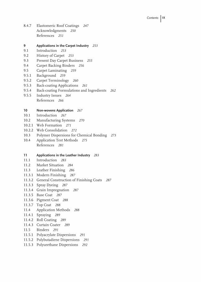
9 Applications in the Carpet Industry 253
9.1 Introduction 253
9.2 History of Carpet 253
9.3 Present Day Carpet Business 255
9.4 Carpet Backing Binders 256
9.5 Carpet Laminating 259
9.5.1 Background 259
9.5.2 Carpet Terminology 260
9.5.3 Back-coating Applications 261
9.5.4 Back-coating Formulations and Ingredients 262
9.5.5 Industry Issues 264
References 266
10 Non-wovens Application 267
10.1 Introduction 267
10.2 Manufacturing Systems 270
10.2.1 Web Formation 271
10.2.2 Web Consolidation 272
10.3 Polymer Dispersions for Chemical Bonding 273
10.4 Application Test Methods 275
References 281
11 Applications in the Leather Industry 283
11.1 Introduction 283
11.2 Market Situation 284
11.3 Leather Finishing 286
11.3.1 Modern Finishing 287
11.3.2 General Construction of Finishing Coats 287
11.3.3 Spray Dyeing 287
11.3.4 Grain Impregnation 287
11.3.5 Base Coat 287
11.3.6 Pigment Coat 288
11.3.7 Top Coat 288
11.4 Application Methods 288
11.4.1 Spraying 289
11.4.2 Roll Coating 289
11.4.3 Curtain Coater 289
11.5 Binders 291
11.5.1 Polyacrylate Dispersions 291
11.5.2 Polybutadiene Dispersions 291
11.5.3 Polyurethane Dispersions 292

X Contents
11.6 Production of Selected Leather Articles 292
11.6.1 Shoe Upper Leather 292
11.6.2 Apparel Leather 293
11.6.3 Automotive Leather 294
11.6.4 Furniture Leathers 295
11.7 Test Methods in Leather Finishing 296
11.7.1 Flexing Endurance 297
11.7.2 Rub-fastness 298
11.7.3 Dry and Wet Adhesion 299
11.7.4 Fastness to Ironing 299
11.7.5 Hot Air Fastness 299
11.7.6 Aging resistance 299
11.7.7 Fogging test 300
11.7.8 Light-fastness 300
11.7.9 Hot light aging 300
References 300
12 Applications for Asphalt Modification 301
12.1 Introduction 301
12.2 Hot Mix Asphalt Paving 303
12.2.1 Asphalt Specification 304
12.2.2 In-line Injection (Pump-in) 311
12.3 Paving with Asphalt Emulsion 313
12.3.1 Applications of Asphalt Emulsions 314
12.3.2 Asphalt Emulsion Tests 317
12.3.3 Polymer Honeycomb Structure in Cured Asphalt Emulsion 317
12.3.4 Asphalt Emulsion Residue Characterization 319
12.3.5 Application Tests for Chip Seal and Microsurfacing 321
12.4 Eco-efficiency Analysis 323
12.5 Concluding Remarks 326
Acknowledgement 326
References 326
13 Applications of Redispersible Powders 329
13.1 Introduction 329
13.2 Manufacturing of Redispersible Powders 330
13.3 Dry Mortar Technology 332
13.4 Markets and Application Areas of Redispersible Powders 333
13.4.1 Adhesives for Ceramic Tiles 334
13.4.2 Tile Grouts 340
13.4.3 Exterior Insulation and Finish Systems and Top Coats 341
13.4.4 Self-leveling Underlayments 345
13.4.5 Patch and Repair Mortars 346
13.4.6 Waterproof Membranes 350
13.5 Summary 353
Contents XI
References 354
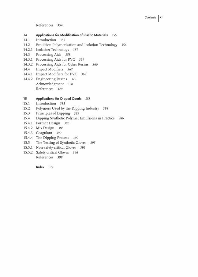
14 Applications for Modification of Plastic Materials 355
14.1 Introduction 355
14.2 Emulsion Polymerization and Isolation Technology 356
14.2.1 Isolation Technology 357
14.3 Processing Aids 358
14.3.1 Processing Aids for PVC 359
14.3.2 Processing Aids for Other Resins 366
14.4 Impact Modifiers 367
14.4.1 Impact Modifiers for PVC 368
14.4.2 Engineering Resins 375
Acknowledgment 378
References 379
15 Applications for Dipped Goods 383
15.1 Introduction 383
15.2 Polymers Used by the Dipping Industry 384
15.3 Principles of Dipping 385
15.4 Dipping Synthetic Polymer Emulsions in Practice 386
15.4.1 Former Design 386
15.4.2 Mix Design 388
15.4.3 Coagulant 390
15.4.4 The Dipping Process 390
15.5 The Testing of Synthetic Gloves 395
15.5.1 Non-safety-critical Gloves 395
15.5.2 Safety-critical Gloves 396
References 398
Index 399

XIII
Preface
Aqueous polymer dispersions are important raw materials used in a variety of in-dustrial processes. They consist of very small polymer particles dispersed in waterand appear as milky fluids. When finally processed and providing the function forwhich they were selected, they are barely visible. Polymer dispersions are used toprotect metal, wood, and leather against water and microorganisms, and are used asbinders for pigments, fillers, and fibers and to finish the surfaces of metal, wood orpaper. Protecting, binding, and finishing are the essential effects achieved by use ofpolymer dispersions.
In most applications the water will be evaporated and a functional polymer re-mains. This can be hard or tacky, plastic or elastic, transparent or opaque. Accord-ingly, they are used for coatings or as adhesives, for binders or foams, for clear coatvarnishes or opacifiers. It is even possible to reconcile these classically contradictoryproperties by proper design of a single dispersion or by mixing several.
Even small amounts of polymer dispersion are able to improve considerably theproperties of different binders, e.g. starch, bitumen, or cement.
The huge variety of applications continues into the area of solid plastic materials –impact modifiers are added to improve the properties of plastic materials. Dippinggoods, e.g. gloves, and latex foams for mattresses are polymeric materials which aremade directly from polymer dispersions.
Finally, there are also applications in which polymer dispersions remain in theirliquid form – they are used as drug carriers, in medical diagnosis, and in liquid soap.
This book focuses on the applications of aqueous polymer dispersions. The chap-ters on synthesis and characterization should be regarded as an introduction andshould aid understanding of the applications. The applications of aqueous polymerdispersions have developed differently, both historically and regionally. Regulatoryissues have contributed to these differences. The strongest development of polymerdispersions occurred in Europe and North America in the middle of the 20th centu-ry. The differences between these two regions are emphasized.
We are specially grateful to all the authors who helped us make this global com-parison and acknowledge the authors’ companies, for approving and supporting thiswork.
Charlotte, North Carolina, USA Dieter UrbanKoichi Takamura


XV
List of Authors
Peter Blanpain7834 Covey Chase DriveCharlotte, NC 28210, USA
Dr. Mary BurchRohm & Haas Company727 Norristown RoadSpring House, PA 19477, USA
Dr. Chuen-Shyong ChouRohm & Haas CompanyRt. 413 and Old Rt. 13Bristol, PA 19007, USA
Dr. Dieter DistlerBASF AktiengesellschaftGKD - B1D-67056 Ludwigshafen, Germany
Dr. Johannes Peter DixBASF AktiengesellschaftEVL/I – G100D-67056 Ludwigshafen, Germany
Dr. Luke EganBASF Corporation11501 Steele Creek RoadCharlotte, NC 28273, USA
Dr. Onno GraalmannBASF Nederland B.V.Westervoortsedijk 71NL-6827 AV Arnhem, The Netherland
Dr. Sunitha GrandheeBASF Corporation26701 Telegraph RoadSouthfield, MI 48034, USA
Richard GrovesSynthomer LTDCentral Road, Templefields, Harlow, Essex, CM20 2BH, UK
Dr. Christoph HahnerWacker Polymer Systems, L. P.3301 Sutton Road Adrian, MI 49221, USA
Dr. Do Ik LeeThe Dow Chemical Company1604 BuildingMidland, MI 48674, USA
Dr. Hermann Lutz Wacker Polymer Systems GmbH&CoKGJohannes-Hees-Str. 24D-84489 Burghausen, Germany
Dr. Werner KirchnerBASF AktiengesellschaftEV/CS – H201D-67056 Ludwigshafen, Germany
Andrew LanhamSynthomer Ltd.Central Road, Templefields, Harlow, Essex, CM20 2BH, UK
Dr. Brough RicheyRohm & Haas Company727 Norristown RoadSpring House, PA 19477, USA
Dr. Jürgen Schmidt-ThümmesBASF AktiengesellschaftGKD/S – B1D-67056 Ludwigshafen, Germany
Dr. Elmar SchwarzenbachBASF AktiengesellschaftEDP/MB – H201D-67056 Ludwigshafen, Germany
Richard ScottBASF Corporation475 Reed Road NWDalton, GA 30720, USA

XVI
J. Arthur SmithBASF Nederland B.V.Westervoortsedijk 71NL-6827 AV Arnhem, The Netherland
K. SpenceleySynthomer Ltd.Central Road, Templefields, Harlow, Essex, CM20 2BH, UK
Barna SzaboFlint Ink Corporation4600 Arrowhead DriveAnn Arbor, MI 48105, USA
Dr. Koichi TakamuraBASF Corporation11501 Steele Creek RoadCharlotte, NC 28273, USA
Jim TangerBASF Corporation11501 Steele Creek RoadCharlotte, NC 28273, USA
Michael A. TaylorBASF Corporation11501 Steele Creek RoadCharlotte, NC 28273, USA
Dr. Dieter UrbanBASF Corporation11501 Steele Creek RoadCharlotte, NC 28273, USA
Dr. Jane E. WeierRohm & Haas CompanyRt. 413 and Old Rt. 13Bristol, PA 19007, USA
Dr. Harm WieseBASF AktiengesellschaftGKD/N – B1D-67056 Ludwigshafen, Germany
Marilyn WolfBASF Corporation11501 Steele Creek RoadCharlotte, NC 28273, USA
Color Plates XVII
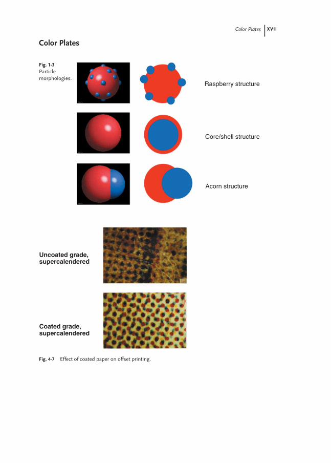
Fig. 4-7 Effect of coated paper on offset printing.
Uncoated grade,supercalendered
Coated grade,supercalendered
Fig. 1-3Particle morphologies.
Raspberry structure
Core/shell structure
Acorn structure
Color Plates

XVIII Color Plates
Fig. 12-15 Photo-micrograph demon-strating spontaneousformation of polymernetwork upon curingof the CRS-2 asphaltemulsion modifiedwith 3 % cationic SBRlatex.
Fig. 8-9 Schematic representation of PSA label coater.
Releaseliner
SteamDryerCoating head
Unwind Rewind
Laminatingstation
Backing
Fig. 4-8 Effect of coated paper on rotogravure printing.
Coatedgravurepaper
Uncoatedgravurepaper
Latex PolymerNetwork
50 µm

1
1
Introduction
Dieter Urban and Dieter Distler
1.1
Names and Definitions
Most precisely the subject of this book is called “aqueous synthetic organic polymercolloids”. The term “polymer colloid” defines a state of subdivision in which polymol-ecular particles dispersed in a medium have at least in one direction a dimension ofroughly between 1 nm and 1000 nm [1]. The term “organic” needs to be added to ex-clude inorganic polymers like silica. To be more precise the term “synthetic” will beadded, if organic polymers of natural origin like natural rubber should be excluded.Finally, the term “aqueous” ensures that the continuous medium is only water, exclud-ing e.g. organic solvents. However, depending on the language, the geographical re-gion and the field of application there are many other names commonly used (Fig. 1-1).
In general the term “dispersion” characterizes a two phase system consisting offinely dispersed solid particles in a continuous liquid phase. An example of a disper-sion is whitewash, calcium hydroxide above the solubility limit in water. If the finelydispersed phase and the continuous phase, both are liquid, the term “emulsion” will be used. An example is milk, which essentially consists of fat droplets in water;the droplets are stabilized by proteins. In both cases, in dispersions and emulsions,the continuous phase is therefore a liquid; in all of our examples, the liquid is water.In dispersions, the finely disperse substance is solid, while in emulsions it is liquid.
Dealing with organic polymers being the dispersed substance it is difficult to de-fine precisely whether they are solid or liquid. Depending on the glass transitiontemperature (Tg) and chain length, polymers are viscous liquids at low Tg and lowmolecular weight or they will be tough to brittle solids, if Tg and molecular weightare high. The temperature and stress duration are other important factors. At tem-peratures below the glass transition temperature or in the case of very short stressduration, polymers behave like glasses, while above this temperature or in the case oflong stress times, they are viscous or elastic materials. This behavior of polymers be-tween liquid and solid is one reason why aqueous synthetic organic polymer colloidsare referred to as dispersions (Danish, Dutch, Finnish, German, Greek, Hungarian,Japanese, Korean, Norwegian, Polish, Portuguese, Romanian, Russian, Spanish,

2 1 Introduction
Fig. 1-1 Commonly used names for aqueous synthetic organic polymercolloids.
1.2 Properties of Polymer Dispersions 3
Swedish, Turkish) and emulsions (Arabic, Chinese, English, Indonesian, Italian,Malay). Another reason for the use of emulsion or emulsion polymer comes from themost important production process for these products, the emulsion polymerization.The products are referred to as emulsion polymers or simply emulsions.
In contrast to this the name latex (Latin: latex, liquid; Greek: λαταξ, droplet) is de-rived from the naturally occurring rubber milk and is most widely used for aqueoussynthetic organic polymer colloids, especially for the substitution products of naturallatex, butadiene-styrene copolymer emulsions.
The Union for Pure and Applied Chemistry recommends two names: Latex andpolymer dispersion [2]. Latex is defined as “A colloidal dispersion of polymer parti-cles in an aqueous medium. The polymer may be organic or inorganic.” Since we will not cover inorganic dispersions, this book should have been called “OrganicLatices and Their Industrial Applications”, which seems to be a pleonasm becausethe use of latex is generally associated with organic material. Polymer dispersion isdefined as “A dispersion in which the disperse phase consists of polymer particles.”The continuous phase can be a liquid, solid or gas. If we want only water to be thecontinuous phase, aqueous is added. In industrial applications non-aqueous poly-mer dispersions are negligible. Therefore this book has been called “Polymer Dis-persions and Their Industrial Applications”. However, according to the preference ofthe authors the terms “polymer dispersion”, “dispersion”, “emulsion polymer”,“emulsion” and “latex” are used synonymously.
1.2
Properties of Polymer Dispersions
The aggregate state of a polymer dispersion is thermodynamically unstable. The verylarge internal surface area of up to 100 m2 mL–1 of dispersion requires stabilizationof the particle surfaces in order to suppress phase separation and coagulation. Dri-ving force for the agglomeration of particles is the gain of energy by reducing the in-ternal surface. Finally a polymer block and a substantially polymer-free water phasewill be formed. This coagulation can be accelerated by salts, acids, solvents, freezing,shear, etc.
To obtain highly stable polymer dispersions, the particles are usually providedwith ionic groups, for example by adsorption of anionic or cationic surfactants, or byincorporation of ionic groups into the polymer. Another, nonionic type of stabiliza-tion takes place via hydrophilic groups on the particle surface, for example by amino-or hydroxyl-containing monomers or protective colloids. Polymer dispersions usedin industry usually are stabilized by both mechanisms (ionic and nonionic). The spe-cial nature of the particle surface, which differs from the particle interior, plays animportant role in all applications.
Industrially important polymer dispersions usually contain 40–60 % of polymer in water. Each mL of dispersion contains about 1015 particles with diameters of50–500 nm. One particle contains 1–10 000 macromolecules, and each macromole-cule contains about 100–106 monomer units (Fig. 1-2).

4 1 Introduction
These figures give an impression of the possible variation, if just the molecularweight (or molecular weight distribution) and particle size (or particle size distribu-tion) of homo-polymers will be considered. The random incorporation of variousmonomers in the chains, the possibility of cross-linking between the polymer chainsand finally separated phases of different polymers in a particle allow a virtually un-limited variety in this product class.
Polymer dispersions normally consist of spherical particles. The dispersed parti-cles scatter the light and are the cause of the milky appearance. This Mie scattering isutilized for particle size measurement. Very small polymer particles hardly scattervisible light at all, those polymer dispersions have a translucent appearance. If all theparticles are of the same size, the term “monodisperse dispersions” will be used.They are frequently recognized from a certain particle size merely from the irides-cent appearance, which is caused by Bragg scattering at a crystalline superstructureof close packing of the particles.
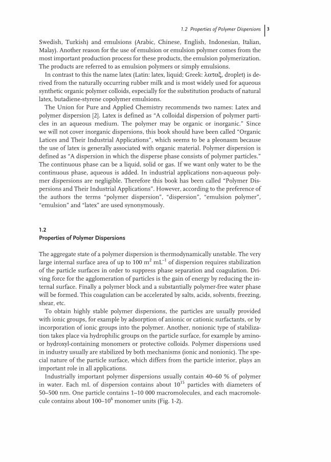
Polymer dispersions with a heterogeneous particle structure – a special particlemorphology consisting of a number of phases – have recently become of interest. Ex-amples are particles with a core/shell structure or two coexistent polymer phases,particles with a raspberry structure, etc. The particle morphology may be thermody-namically preferred; in the case of polymers with reduced chain mobility or even inthe case of relatively low cross-linking, it is mostly kinetically controlled morpholo-gies that are frozen. This enables product properties with even contradictory require-ments to be achieved better, for example low film formation temperature, but maxi-mum blocking resistance or hardness of the polymer (Fig. 1-3).
The flow behavior is also an important parameter. The flow property of polymerdispersions is a particular advantage of this aggregate state. Dispersions can have apolymer content which is a multiple higher than polymer solutions, yet still be free-flowing. Besides the polymer content, particle size, particle size distribution andelectrolyte content, the viscosity is also affected by dissolved constituents in the aque-ous phase. The water phase of many polymer dispersions contains a whole range ofwater-soluble oligomers, auxiliaries and additives which contribute to the applicationproperties as well.
Fig. 1-2 What is a polymer dispersion?
1.2 Properties of Polymer Dispersions 5
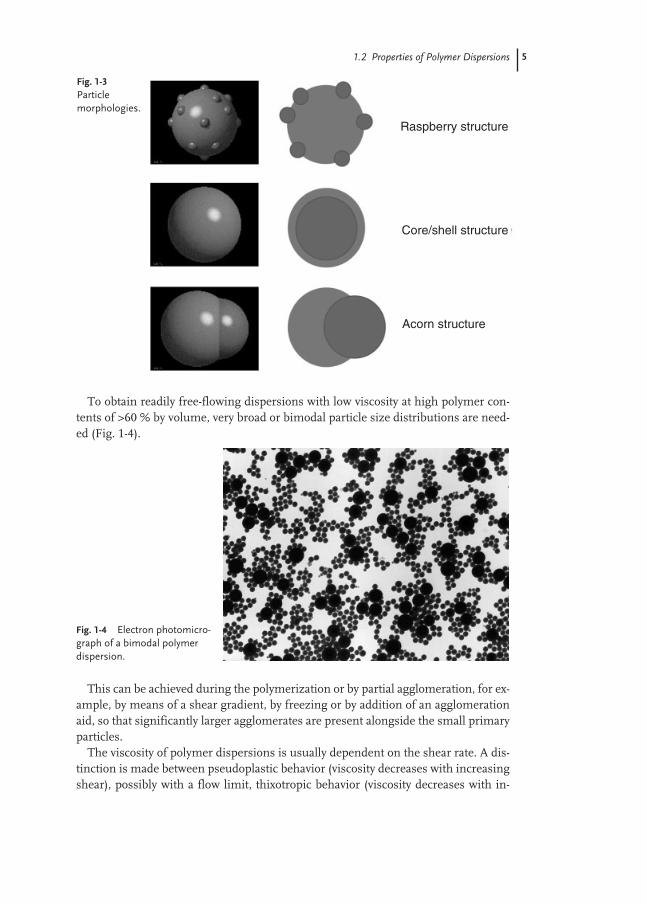
To obtain readily free-flowing dispersions with low viscosity at high polymer con-tents of >60 % by volume, very broad or bimodal particle size distributions are need-ed (Fig. 1-4).
This can be achieved during the polymerization or by partial agglomeration, for ex-ample, by means of a shear gradient, by freezing or by addition of an agglomerationaid, so that significantly larger agglomerates are present alongside the small primaryparticles.
The viscosity of polymer dispersions is usually dependent on the shear rate. A dis-tinction is made between pseudoplastic behavior (viscosity decreases with increasingshear), possibly with a flow limit, thixotropic behavior (viscosity decreases with in-
Fig. 1-3Particle morphologies.
Fig. 1-4 Electron photomicro-graph of a bimodal polymerdispersion.
Raspberry structure
Core/shell structure
Acorn structure

6 1 Introduction
creasing shear time) and dilatant behavior (viscosity increases with increasingshear). The rheology of concentrated polymer dispersions is complex, often being de-pendent on the shear rate and previous history.
Owing to the content of surface-active substances, the foaming behavior is an im-portant property for many applications. Antifoam agents reduce foaming, while fur-ther emulsifiers and rheology modifiers increase the foaming or stabilize the foamonce formed.
The biodegradability of many additives makes the dispersions susceptible to attackby microorganisms (bacteria, yeast). Most dispersions are therefore provided withbiocides.
In most applications, the water is evaporated from the dispersions. Depending onthe composition and/or processing temperature, a polymer film or powder is formed.The properties of the polymer now come into play:
strength, elongation at break, elasticity, transparency, solvent and environmentalresistance, glass transition temperature, tack, etc.
These properties are determined by the chemical composition of the copolymers,the molecular weight and the molecular weight distribution, by the morphology ofthe polymer particles and by the morphology of the polymer film.
Important polymer classes are:Styrene/butadiene dispersions are used for their elastic properties since molecular
weight and cross-linking of the polymer can be adjusted widely by choosing the de-gree of conversion and the amount of chain transfer agents. They are used as syn-thetic rubber for tires and molded foam. When styrene is replaced by acrylonitrile,elastic and solvent resistant polymers are obtained, which are used for dippinggoods. Carboxylated styrene/butadiene (XSB) dispersions contain acrylic, methacryl-ic, maleic, fumaric or itaconic acid. The carboxylic groups provide stabilization of thepolymer particles and a good interaction with fillers (calcium carbonate, clay) andpigments. The main applications are paper coating and carpet backing. The remain-ing 1,2 and 2,3 double bonds of butadiene favor autoxidation of the polymer, it be-comes yellow and brittle. This is prevented by adding antioxidants. This polymerclass is resistant to hydrolysis at all pH values since it does not contain ester unitswhich tend to hydrolyze especially at very high pH.
Acrylic dispersions (pure acrylics and styrene acrylics) are extremely versatile. Thebig variety of available acrylic and methacrylic esters together with styrene offeralmost unlimited opportunities to choose for the glass transition temperature andthe hydrophilic/hydrophobic properties. Acrylic esters tend to form cross-linkedpolymers by abstraction of the α-hydrogen atom, methacrylic esters in contrast formpolymer chains which are not cross-linked. Acrylics are resistant against oxidation byair and degradation by light. The main application areas are coatings and adhesives.
Vinyl acetate dispersions are widely used for coatings and adhesives as well. Tostabilize the polymer particles often polyvinyl alcohol is used as protective colloid.Most common co-monomers are ethylene, versatic esters, vinyl chloride or acrylic es-ters. The polymer dispersions are spray dried to obtain a polymer powder, which iswidely used in construction industry. Ethylene/vinyl acetate copolymers form elasticfilms and are fairly resistant to oxygen and light.
1.2 Properties of Polymer Dispersions 7
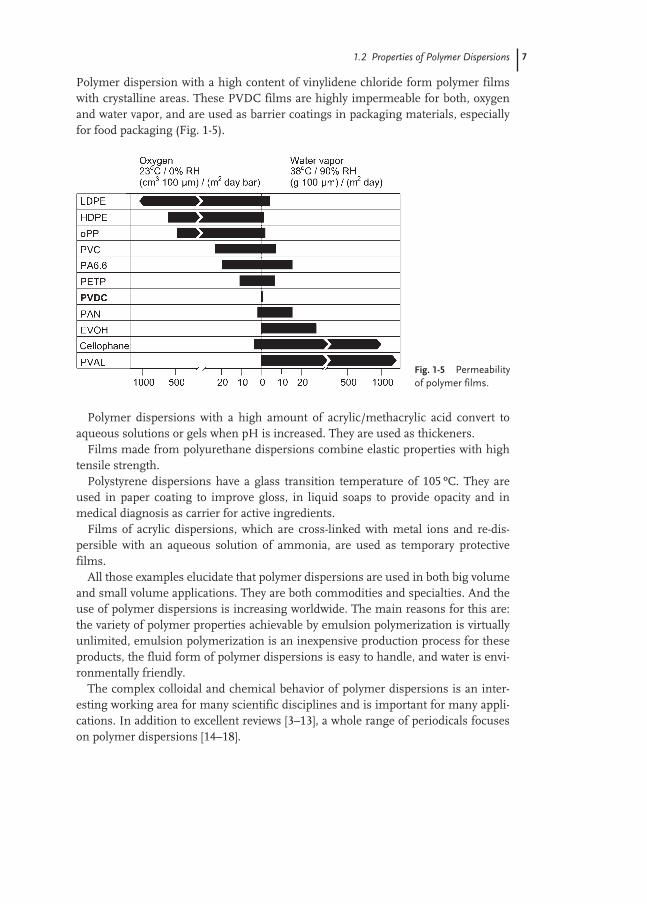
Polymer dispersion with a high content of vinylidene chloride form polymer filmswith crystalline areas. These PVDC films are highly impermeable for both, oxygenand water vapor, and are used as barrier coatings in packaging materials, especiallyfor food packaging (Fig. 1-5).
Polymer dispersions with a high amount of acrylic/methacrylic acid convert toaqueous solutions or gels when pH is increased. They are used as thickeners.
Films made from polyurethane dispersions combine elastic properties with hightensile strength.
Polystyrene dispersions have a glass transition temperature of 105 ºC. They areused in paper coating to improve gloss, in liquid soaps to provide opacity and inmedical diagnosis as carrier for active ingredients.
Films of acrylic dispersions, which are cross-linked with metal ions and re-dis-persible with an aqueous solution of ammonia, are used as temporary protectivefilms.
All those examples elucidate that polymer dispersions are used in both big volumeand small volume applications. They are both commodities and specialties. And theuse of polymer dispersions is increasing worldwide. The main reasons for this are:the variety of polymer properties achievable by emulsion polymerization is virtuallyunlimited, emulsion polymerization is an inexpensive production process for theseproducts, the fluid form of polymer dispersions is easy to handle, and water is envi-ronmentally friendly.
The complex colloidal and chemical behavior of polymer dispersions is an inter-esting working area for many scientific disciplines and is important for many appli-cations. In addition to excellent reviews [3–13], a whole range of periodicals focuseson polymer dispersions [14–18].
Fig. 1-5 Permeabilityof polymer films.
8 1 Introduction
1.3
Important Raw Materials
The most important production process for polymer dispersions is emulsion poly-merization [19]. This process is started by preparing a monomer emulsion consist-ing of monomer droplets in water. The monomer droplets are stabilized by emulsi-fiers and/or protective colloids. When adding an initiator polymerization is startedconverting the monomers into polymer particles (Chapter 2).
The production of polymer dispersions by emulsion polymerization requires de-ionized water, free-radical-polymerizable monomers, emulsifiers and/or protectivecolloids and initiators. Further auxiliaries, such as chain transfer agents, buffers,acids, bases, anti-aging agents, biocides, etc., can be used.
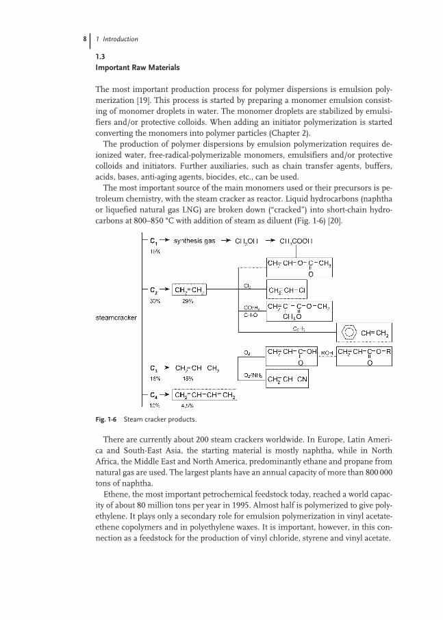
The most important source of the main monomers used or their precursors is pe-troleum chemistry, with the steam cracker as reactor. Liquid hydrocarbons (naphthaor liquefied natural gas LNG) are broken down (“cracked”) into short-chain hydro-carbons at 800–850 °C with addition of steam as diluent (Fig. 1-6) [20].
There are currently about 200 steam crackers worldwide. In Europe, Latin Ameri-ca and South-East Asia, the starting material is mostly naphtha, while in NorthAfrica, the Middle East and North America, predominantly ethane and propane fromnatural gas are used. The largest plants have an annual capacity of more than 800 000tons of naphtha.
Ethene, the most important petrochemical feedstock today, reached a world capac-ity of about 80 million tons per year in 1995. Almost half is polymerized to give poly-ethylene. It plays only a secondary role for emulsion polymerization in vinyl acetate-ethene copolymers and in polyethylene waxes. It is important, however, in this con-nection as a feedstock for the production of vinyl chloride, styrene and vinyl acetate.
Fig. 1-6 Steam cracker products.

1.3 Important Raw Materials 9
Propene cannot be polymerized by means of free radicals. It is, however, a feed-stock for acrylic acid, acrylates and acrylonitrile.
Butadiene is extracted from the C4 fraction from the steam cracker, and can beused directly for emulsion polymerization.
The principal monomers butadiene, styrene, vinyl acetate, (meth)acrylates andacrylonitrile essentially determine the material properties of films made from thecorresponding dispersions: the glass transition temperature, the water absorptioncapacity, the elasticity, etc. Auxiliary monomers, which are only used in a small pro-portion, usually <5 %, control important properties such as colloid-chemical stabi-lization (acrylic acid, methacrylic acid, acrylamide, methacrylamide), crosslinkingwithin the particles (difunctional acrylates, divinylbenzene, etc.) or hydrophilic prop-erties (OH-containing monomers, such as hydroxyacrylates). Reactive monomerswhich still contain a latently reactive group even after incorporation into the poly-mer, for example glycidylmethacrylate or N-methylol(meth)acrylamide, can form anetwork between various particles and polymer molecules after film formation.
These specific polar groups are frequently not distributed homogeneously over theparticle cross-section, but are preferentially moved to the area of greatest effective-ness, for example the particle surface.
Besides the monomers, the emulsifiers are important constituents. Emulsifiers(surfactants) consist of a long-chain hydrophobic group (dodecyl, hexadecyl or alkyl-benzene) and a hydrophilic end group.
The hydrophilic group may be anionic (sulfate, sulfonate, sulfosuccinic acid, phos-phate, carboxylate) or cationic (quaternary ammonium salts) or have a zwitterionicstructure (betaine groups).
In addition, there is a whole series of nonionic emulsifiers and protective colloids,which are frequently used in combination with ionic emulsifiers. Ethylene oxide-propylene oxide block copolymers, amphiphilic 2- and 3-block copolymers, polyvinylalcohols, polyvinyl-pyrrolidone, alkylpolyglycol ethers, etc.
For the polymerization to start and maintain, a free-radical initiator which formsfree radicals at elevated temperatures (60–100 ºC) is needed, for example sodiumperoxodisulfate, hydrogen peroxide, organic peroxides or azo compounds, or a redoxsystem, for example hydrogen peroxide/ascorbic acid with Fe2+ salts.
The polymerization can also be initiated by UV, γ-rays, electron beams or strongsound or shear fields, although these, apart from UV initiation, have not yet beenused in practice.
The combination of initiator- and surface-active properties (inisurf) or surface-active and monomer properties (surfmer) in a single molecule is possible, but is sofar mainly of academic interest.

10 1 Introduction
1.4
Commercial Importance of Polymer Dispersions
Polymers were discovered in the 1920s. During World War II large industrial scaleproduction was established and since the 1950s production and use of polymers havegrown strongly (Fig. 1-7).
This growth is ongoing, and production of synthetic polymers has reached about189 million metric tons with a total value of more than US$ 200 billion worldwide bythe year 2000. This growth is due to two factors: the ability of polymers to combineproperties such as light weight, strength, electrical insulation, etc., and the extreme-ly low energy content (as product and in production). The possibility of energy recov-ery, recycling of the raw material or even of the polymer after use conserves re-sources. We encounter a wide range of polymers every day in the form of fibers, ma-terials, films, etc., in virtually all products we use in everyday life. Combinations ofthe various product classes make a significant contribution toward the variety of endproducts made of plastic materials and synthetic fibers. The variety of functionalpolymers is even greater than for plastics and fibers. Functional polymers are usedas polymer solutions, polymer dispersions or polymer powders. They essentially per-form the functions of protecting, binding, bonding and finishing.
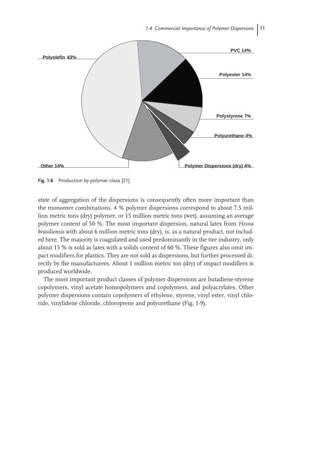
The major polymer classes – polyolefins, polyvinyl chloride and polystyrene – aredefined by their monomers; ethene, propene, vinyl chloride and styrene (Fig. 1-8).
These three groups together account for 64 % of synthetic polymers. The class ofpolymer dispersions is only described by the state of aggregation, but not by thechemical composition. In the chapters dealing with applications, we will also see thatfor a particular application a number of polymer classes are suitable; the specific
Fig. 1-7 Growth of plastics production.
0
20
40
60
80
100
120
140
160
180
200
1960 1970 1980 1990 2000
Million Metric tons
189
8 32
68
114
1.4 Commercial Importance of Polymer Dispersions 11
state of aggregation of the dispersions is consequently often more important thanthe monomer combinations. 4 % polymer dispersions correspond to about 7.5 mil-lion metric tons (dry) polymer, or 15 million metric tons (wet), assuming an averagepolymer content of 50 %. The most important dispersion, natural latex from Heveabrasiliensis with about 6 million metric tons (dry), is, as a natural product, not includ-ed here. The majority is coagulated and used predominantly in the tire industry, onlyabout 15 % is sold as latex with a solids content of 60 %. These figures also omit im-pact modifiers for plastics. They are not sold as dispersions, but further processed di-rectly by the manufacturers. About 1 million metric ton (dry) of impact modifiers isproduced worldwide.
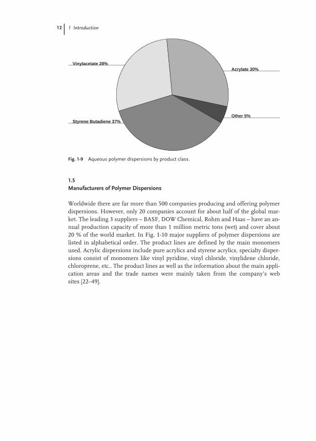
The most important product classes of polymer dispersions are butadiene-styrenecopolymers, vinyl acetate homopolymers and copolymers, and polyacrylates. Otherpolymer dispersions contain copolymers of ethylene, styrene, vinyl ester, vinyl chlo-ride, vinylidene chloride, chloroprene and polyurethane (Fig. 1-9).
Fig. 1-8 Production by polymer class [21].
Other 14%
Polyurethane 4%
PVC 14%
Polyolefin 43%
Polymer Dispersions (dry) 4%
Polyester 14%
Polystyrene 7%
12 1 Introduction
1.5
Manufacturers of Polymer Dispersions
Worldwide there are far more than 500 companies producing and offering polymerdispersions. However, only 20 companies account for about half of the global mar-ket. The leading 3 suppliers – BASF, DOW Chemical, Rohm and Haas – have an an-nual production capacity of more than 1 million metric tons (wet) and cover about20 % of the world market. In Fig. 1-10 major suppliers of polymer dispersions arelisted in alphabetical order. The product lines are defined by the main monomersused. Acrylic dispersions include pure acrylics and styrene acrylics, specialty disper-sions consist of monomers like vinyl pyridine, vinyl chloride, vinylidene chloride,chloroprene, etc.. The product lines as well as the information about the main appli-cation areas and the trade names were mainly taken from the company’s websites [22–49].
Fig. 1-9 Aqueous polymer dispersions by product class.
Styrene Butadiene 37%Other 5%
Acrylate 30%Vinylacetate 28%

1.5 Manufacturers of Polymer Dispersions 13
Fig. 1-10 Major suppliers of aqueous poly-mers dispersions. Product lines: A acrylic disper-sions, SB styrene butadiene dispersions, NBacrylonitrile butadiene dispersions, VAc vinylacetate dispersions, EVA ethylene vinyl acetate
dispersions, PU polyurethane dispersions, Sp specialty dispersions. Applications: Adh adhesives, Coat coatings/paints, Con construc-tion/building products, I/GA inks/graphic arts,Pap paper, Tex carpet/textile/non-woven.
Company Product lines Applications Trade names
Air Products [1-22] VAc, EVA, A Adh, Coat, Con, I/GA, Pap, Tex Airbond, Airflex, Flexbond, Flexcryl,Valbond, Valtac, Vancryl, Vinac
Asahi Kasei [1-23] A, Sp Adh, Coat Polytron, Sun WrapAvecia[1-24] A, PU Adh, Coat, I/GA NeoCryl, NeoRes, NeoPac,
NeoRad, HaloflexBASF [1-25] A, SB, PU, Sp Adh, Coat, Con, Pap, Tex Acronal, Basonal, Butofan, Butonal,
Diofan, Emuldur, Luhydran, Luphen,Styrofan, Styronal
Clariant [1-26] VAc, EVA, A, Adh, Coat, Con, Tex Mowilith, Mowiplus, AppretanDow [1-27] SB, A, VAc,
PU,Coat, Con, Pap, Tex Dow Latex, UCAR Latex
Eastman Chem. [1-28] A, VAc Adh, Coat, I/GA Eastek, Eastarez, WaterbornePolymer
Elf Atochem [1-29] A, EVA, VAc Adh, Coat, Con, I/GA, Pap, Tex RepolemEnichem [1-30] SB, NB Adh, Pap, Tex Intex, Europrene, LaticeGoodyear [1-31] A, SB, Sp Adh, Coat, Con, Tex Pliolite, PliotecBFGoodrich [1-49] A, NB, SB, PU,
SpAdh, Coat, Con, Tex Aqueous XPD, Carbotac, Carboset,
Carbobond, Goodrite, Hycar,Hystrech, Sancure, Vycarnow Noveon
JSR Corporation [1-32] A, SB Adh, Coat, Con, Pap Glasca, DynaflowS.C. Johnson [1-33] A, PU Adh, Coat, I/GA Joncryl, SCXMitsubishi Chem [1-34] A, EVA, VAc,
PUAdh, Coat, Con, Pap, Tex Rikabond
National Starch [1-35] A, EVA, VAc, Adh, Coat, Con, I/GA, Pap, Tex Vinamul, Dur-o-set, Dur-o-cryl,Nacrylic, Resyn
Nitriflex [1-36] NB, SB, Sp Adh, Tex Nitrilatex
Zeon Corp. [1-37] A, SB, NB Adh, Coat, Con, I/GA, Pap, Tex Nipol
Omnova [1-38] A, SB, NB,VAc, Sp
Adh, Coat, Con, I/GA, Pap, Tex AcryGen, GenFlo, SunCryl,AcrylGen, AcrylPrint, GenCal,GenCryl, GenTac, OmnaBloc,Sequabond, Sunbond
Polymer Latex [1-39] A, NB, SB, PU,Sp
Adh, Coat, Con, Pap, Tex Acralen, Baystal, Baypren, Bunatex,Lipaton, Lipolan, Plextol, Perbunan
Raisio Group [1-40] A, SB, Vac Pap, Tex RaisionalReichold [1-41] A, EVA, NB,
SB, VAc, SpAdh, Coat, Con, I/GA, Pap, Tex Elvace, Pace, Plyamul, Synthemul,
TylacRevertex [1-42] EVA, VAc Adh DurabondRhodia [1-43] A, VAc, SB Adh, Coat, Con, Pap, Tex Rhodopas, Rhodotak, RhoximatRohm&Haas [1-44] A, VAc, PU Adh, Coat, Con, I/GA, Pap, Tex Lucidene, Primal, Polyco, Rhobond,
Rhopaque, Rhoplex, RovaceSolutia Inc. [1-45] A Adh GelvaSynthomer [1-46] A, NB, SB Adh, Con, I/GA, Pap, TexUCB [1-47] A, PU Adh, Coat Ucecryl, UcecoatWacker [1-48] EVA, VAc, Sp Adh, Coat, Con Vinnapas, Wacker SMK

14
References
1 Everett, D. H., Pure Appl. Chem. 31(4),579–638, 1972.
2 IUPAC Proposal for The nomenclaturefor Polymerization Processes and Poly-mers in Dispersed Systems. See alsoISO 12000 Plastics/rubber-Polymer dis-persions and rubber latices – Definitionsand review of test methods.
3 Blackley, D. C., High Polymer Lattices,two volumes, MacLaren, London, 1966.
4 Warson, H., The Application of SyntheticResin Emulsions, Benn, London, 1972.
5 Piirma, I., Emulsion Polymerisation, Academic Press, New York, 1982.
6 Blackley, D. C., Emulsion Polymerisation,Theory and Practice, Applied Science,London, 1975.
7 Hölscher, F., Dispersions of SyntheticHigh Polymers, Part I, Properties, Prepara-tion, Testing, Springer, Berlin, 1969.
8 Reinhard, H., Dispersions of SyntheticHigh Polymers, Part II, Use, Springer,Berlin, 1969.
9 Buscall, R., Corner, T., Stagemann, J. F., Polymer Colloids, Elsevier AppliedScience, London, 1985.
10 Athey, R. D., Emulsion Polymer Tech-nology, Marcel Dekker, New York, 1991.
11 Poehlein, G., Encyclopedia of Polymer Science and Engineering; Volume 6, Emulsion Polymerisation, J. Wiley, New York, 1986.
12 Lovell, P. A., El-Asser, M. S., EmulsionPolymerisation and Emulsion Polymers, J.Wiley, New York, 1997.
13 Asua, J. M., Polymeric Dispersions: Principles and Applications, (NATO ASI Series E: Appl. Science, Vol. 335),Kluwer Academic Publishers, Dordrecht,1997.
14 Colloid Polym. Sci., Steinkopf.15 Colloids Surf., Elsevier.16 J. Colloid Interface Sci., Academic Press.17 Langmuir, ACS Journal of Surfaces and
Colloids, American Chemical Society.
18 J. Dispersion Sci. Technol., Coden.19 Gilbert, R., G., Emulsion Polymerisation,
A Mechanistic Approach, AcademicPress, London, 1995.
20 Weissermel, K., Arpe, H.-J., IndustrialOrganic Chemistry, Major Organic Precursors and Intermediates, VerlagChemie, Weinheim, 1994.
21 P. Baum, J. Engelmann, Nachrichtenaus der Chemie, 49/3, 368f, 2001.
22 http://www.airproducts.com23 http://www.asahi-kasei.co.jp/asahi/
english/kasejusi.htm24 http://www.avecia.com/neoresins/25 http://www.basf.de/de/dispersionen/
products26 http://www.clariant.com27 http://www.dow.com/emulpoly/
index.html 28 http://www.eastman.com/29 http://www.atofina.com/30 http://www.enichem.it/english/31 http://www.goodyear.com/32 http://www.jsr.co.jp/main/english/33 http://www.scjohnsonwax.com/34 http://www.m-kagaku.co.jp/35 http://www.Vinamulpolymers.com/36 http://www.nitriflex.com.br/37 http://www.zeon.co.jp/38 http://www.omnova.com/39 http://www.polymerlatex.de/40 http://www.raisiogroup.com/41 http://www.reichhold.com/42 http://www.revertexfinewaters.com/43 http://www.rhodia.com/44 http://www.rohmhaas.com/45 http://www.solutia.com/46 http://www.synthomer.com/47 http://www.ucb.be/48 http://www.wacker.com/vip/
produktion/wacker/website/polymer-systems/index_en.html
49 http://www.bfgsolutions.com

15
2
Synthesis of Polymer Dispersions
Mike A. Taylor
2.1
Introduction
The intent of this chapter is to give a short overview of the chemistry and manufac-turing processes involved in the synthesis of emulsion polymers. While the equip-ment used in preparing an emulsion polymer is relatively simple, and the mecha-nism of the important reactions are fairly well understood, the development of newand improved products is often still carried out in a somewhat empirical fashion.Recipe and process conditions can frequently be designed, based on a theoreticalknowledge, to produce specific polymeric and colloidal properties, but there are stilllarge gaps in the knowledge needed to translate this into application behavior. Ingeneral, scale-up from laboratory to manufacturing gives good duplication of poly-meric and colloidal properties, and laboratory equipment normally consists of sim-ple stirred reactors, usually glass for non-pressure polymerizations, with a means ofmaintaining temperature control of the exothermic reaction. With non-pressure re-actors, ingredients may be added under gravity, while pumps or inert gas pressuremay be used for pressurized systems. Two important process features that are not re-produced well between small and large-scale reactors are heat transfer and shear.Laboratory reactors, with their large cooling surface to volume ratio and the largeheat capacity of the reactor relative to the contents, do not normally pose any prob-lems for cooling. In fact, heat losses often exceed heat generated by the reaction, ne-cessitating heat input to maintain reaction temperature. Heat transfer, on the otherhand, often limits production rates in large-scale reactors. In order to achieve a sim-ilar degree of mixing in vessels of different sizes, the most important scale-up crite-ria is usually to maintain the same power input per unit volume. Unfortunately, thistranslates to a higher agitation speed as reactor size reduces, a consequence of whichis increased shear on the emulsion. Therefore, for the study of process characteris-tics, laboratory reactors have significant limitations.
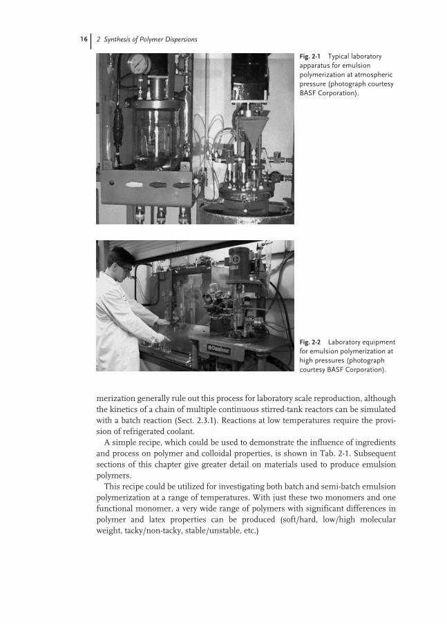
Figures 2-1 and 2-2 show modern laboratory facilities for non-pressure and pres-sure emulsion polymerization. Both batch and semi-batch reactions are regularlycarried out on laboratory scale. The larger quantities involved in continuous poly-
16 2 Synthesis of Polymer Dispersions
merization generally rule out this process for laboratory scale reproduction, althoughthe kinetics of a chain of multiple continuous stirred-tank reactors can be simulatedwith a batch reaction (Sect. 2.3.1). Reactions at low temperatures require the provi-sion of refrigerated coolant.
A simple recipe, which could be used to demonstrate the influence of ingredientsand process on polymer and colloidal properties, is shown in Tab. 2-1. Subsequentsections of this chapter give greater detail on materials used to produce emulsionpolymers.
This recipe could be utilized for investigating both batch and semi-batch emulsionpolymerization at a range of temperatures. With just these two monomers and onefunctional monomer, a very wide range of polymers with significant differences inpolymer and latex properties can be produced (soft/hard, low/high molecularweight, tacky/non-tacky, stable/unstable, etc.)
Fig. 2-1 Typical laboratoryapparatus for emulsionpolymerization at atmosphericpressure (photograph courtesyBASF Corporation).
Fig. 2-2 Laboratory equipmentfor emulsion polymerization athigh pressures (photographcourtesy BASF Corporation).

2.2 Chemistry 17
2.2
Chemistry
2.2.1
Mechanism of Emulsion Polymerization
Strictly speaking, emulsion polymerization can take place in a system with only threecomponents, a monomer that forms the structure of the polymer, water that acts asthe continuous medium in which the polymer particles are dispersed, and an initia-tor that produces free radicals which start and maintain the polymerization process.However, at the very least the system will almost invariably contain a fourth ingredi-ent, surfactant, which can provide the initial site, from which polymer particles sub-sequently grow, and/or give stability to the growing particles. In addition, most com-mercial recipes would normally include other ingredients to impart specific proper-ties to the final polymer or emulsion, for example, a modifier to control the molecu-lar weight of the polymer or a cross-linking agent to control the amount of gel. Inmany cases, ingredients used to control polymerization behavior will also exert theirown influence on application properties of the final emulsion. Particularly, surfac-tants, while often determining the number of particles and their stability, can alsohave significant effects on such properties as adhesion, rheology, filler tolerance andmany others. The overall formulation of an emulsion polymer is therefore often acompromise to obtain an optimum balance of properties. Rarely can the best ofeverything be achieved.
The basic building block of any polymer is the monomer, characterized as a mole-cule containing at least one carbon-carbon double bond, C=C, and which, through a
Tab. 2-1 Model system for the study of some aspects of emulsionpolymerization.
Ingredient Quantity Influence(phm1)
Water 100–150 Solids content; viscosityStyrene 0–95 Glass transition temp;
minimum film-formingn-Butyl acrylate 0–95 Glass transition temp;
minimum film-formingMethacrylic acid 0–5 Colloidal stability; viscosity;
reaction kineticsSodium lauryl sulfate 0.5–3.0 Particle size; colloidal stability;
reaction kineticsAmmonium persulfate 0.1–1.0 Particle size; colloidal stability;
viscosity; reaction kinetics; molecular wt.
t-Dodecyl mercaptan 0–1.0 Molecular wt.; reaction kineticsDivinylbenzene 0–0.5 Cross-linking/gel
1 Parts per hundred parts of monomer
18 2 Synthesis of Polymer Dispersions
free radical mechanism, can add on to itself, ultimately forming very large moleculesof repeating units. Many different monomers (Sect. 2.2.2) are in use commerciallyfor producing emulsion polymers, either as the sole monomer or, more usually, ascombinations of monomers to give specifically desired properties. Polymerization isstarted when a free radical, originating from the decomposition of the initiator(Sect. 2.2.5), comes into contact with a monomer molecule and adds on at the site ofthe C=C double bond. This creates a monomer unit that is then itself a free radicaland can in turn add on to another monomer molecule. The process continues, build-ing up long chains of monomer units, until the free radical at the end of the chaincomes into contact with some species other than a monomer molecule, normally an-other free radical, at which time the growing polymer chain is terminated. The freeradical that terminates the chain can be an original radical, from the decompositionof the initiator, or a “polymeric radical” when the ends of two propagating chainsterminate each other. Other species, such as inhibitors and short-stopping agents ifpresent, can also cause termination to occur. These three main stages of polymeriza-tion are termed initiation, propagation and termination and can be denoted schemat-ically as follows:
Initiation Ι → 2R• (decomposition of initiator)M + R• → R–M•
Propagation R–M(n)• + M → R–M(n + 1)•
or transfer to polymer leading to branching
R–M(n)• + R–M(m)–R → R–M(n) + R–M•(m)–RTermination R–M(n + 1)• + R• → R–M(n + 1)Ror R–M(n)• + R–M(m)• → R–M(n + m)–R
In such a system, the average molecular weight of the polymer chains is controlledprimarily by the temperature of polymerization and the quantity of initiator. To exertadditional control over molecular weight, a molecular weight modifier (chain trans-fer agent) is used. With chain transfer, a growing polymer chain is terminated but atthe same time another radical is generated which can initiate polymerization of afurther monomer unit, thus starting another polymer chain. Widely used chaintransfer agents are the mercaptans, R–SH, where R is typically a twelve to fourteenhydrocarbon (t-dodecyl or n-dodecyl being the most common).
Chain Transfer R–M(n)• + R–SH → R–M(n)–SH + R•
These four mechanisms are common to all types of free-radical polymerizations,for example bulk, solution, suspension and emulsion. The difference between theprocesses is the environment. In bulk polymerization there exists only one phase,initially the monomer, then as polymerization progresses a solution of the polymerin its own monomer. Both polystyrene and poly(methyl methacrylate) are producedin large quantities by bulk polymerization. Solution polymerization is similar in thatthere is only one phase present, but in this case the monomer is diluted with a fullymiscible solvent and the final polymer is in solution in the solvent. Polyacrylic acid,with the solvent being water, is produced by this technique. In suspension polymer-

2.2 Chemistry 19
ization, the monomer is dispersed in droplet form in a continuous medium that isusually water. The size of the droplets is typically in the range ten to one hundred mi-crons. This process would be favored where an aqueous based polymer is required,but where the polymer is insoluble in the monomer. Polyvinyl chloride dispersionsare made in this way.
Emulsion polymerization is also carried out in a continuous water phase, but inthis case the site of polymerization is a far smaller entity than dispersed monomerdroplets, as is the size of the final polymer particles. Harkins [1, 2] developed a quan-titative theory describing emulsion polymerization in an ideal system. This earlymodel is still basically accepted today, and is described briefly as follows. In thisprocess, monomer is “solubilized” within clusters of surfactant molecules, termedmicelles, which form the nucleus of the polymer particle. or a pre-formed polymerparticle of very small size, usually less than 50 nm, which is used as the seed for fur-ther polymerization. In the case of micellar nucleation, many surface active agents,when dissolved in water above a certain concentration (Critical Micelle Concentra-tion or CMC), will form ordered clusters of molecules, with the hydrophobic portionof the molecule oriented toward the center of the cluster and the hydrophilic portiontoward the outside. The size of these micelles is typically about 4 nm, the generalshape being either spherical or lamellar. When a sparingly water-soluble monomer(which describes most of the monomers used in emulsion polymerization) is addedto an aqueous solution containing these micelles, it becomes distributed in threesites; relatively large monomer droplets stabilized by surfactant molecules at thedroplet surface, monomer molecules in solution in the water, and monomer mole-cules that diffuse into the micelles. The inside of the micelle, with the high concen-tration of the hydrophobic portions of the surfactant, provides an attraction for thehydrophobic monomer that diffuses through the water and swells the micelle. Thesemonomer-swollen micelles are limited in size by hydrodynamic forces and interfa-cial tension. The number of monomer-swollen micelles in such a system is orders ofmagnitude greater than the number of monomer droplets present, and as a conse-quence the ratio of the surface areas is similarly large. For example, a dispersion of50 weight percent monomer droplets in water would contain typically about 1010
monomer droplets per liter, whereas a system containing water, soap solution at aconcentration greater than the CMC, and monomer could contain 1017–1019
monomer-swollen micelles per liter. This represents a total surface area of theswollen micelles approximately 105 times that of the monomer droplets. The conse-quence of this is that when free radicals are produced in the aqueous phase of a sys-tem containing water, surfactant and monomer, the free radical has a far greaterprobability of entering a micelle and initiating polymerization than it has of enteringa monomer droplet. Also, the overall rate of polymerization, which is the rate perparticle multiplied by the number of polymerizing particles, is greatly enhanced inthe micellar system.
In most cases, the initiators used in emulsion polymerization are water soluble,and the decomposition, either thermal or with the use of a reducing agent, to pro-duce free radicals takes place in this phase. It is most probable that polymerizationalso starts in the aqueous phase, with free radicals initiating monomer molecules in
20 2 Synthesis of Polymer Dispersions
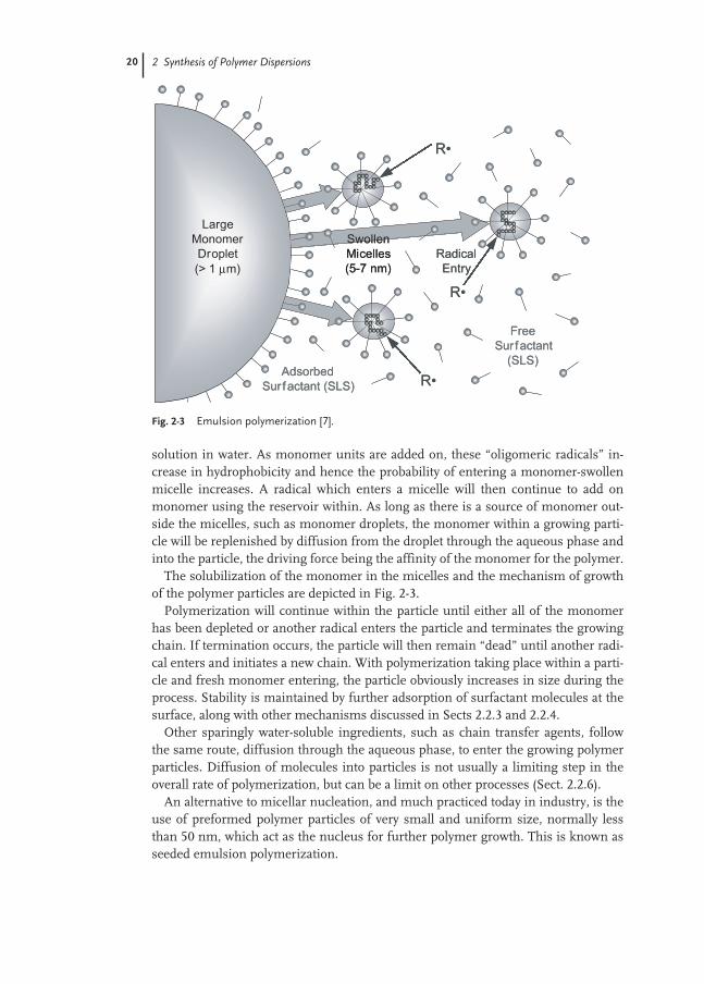
solution in water. As monomer units are added on, these “oligomeric radicals” in-crease in hydrophobicity and hence the probability of entering a monomer-swollenmicelle increases. A radical which enters a micelle will then continue to add onmonomer using the reservoir within. As long as there is a source of monomer out-side the micelles, such as monomer droplets, the monomer within a growing parti-cle will be replenished by diffusion from the droplet through the aqueous phase andinto the particle, the driving force being the affinity of the monomer for the polymer.
The solubilization of the monomer in the micelles and the mechanism of growthof the polymer particles are depicted in Fig. 2-3.
Polymerization will continue within the particle until either all of the monomerhas been depleted or another radical enters the particle and terminates the growingchain. If termination occurs, the particle will then remain “dead” until another radi-cal enters and initiates a new chain. With polymerization taking place within a parti-cle and fresh monomer entering, the particle obviously increases in size during theprocess. Stability is maintained by further adsorption of surfactant molecules at thesurface, along with other mechanisms discussed in Sects 2.2.3 and 2.2.4.
Other sparingly water-soluble ingredients, such as chain transfer agents, followthe same route, diffusion through the aqueous phase, to enter the growing polymerparticles. Diffusion of molecules into particles is not usually a limiting step in theoverall rate of polymerization, but can be a limit on other processes (Sect. 2.2.6).
An alternative to micellar nucleation, and much practiced today in industry, is theuse of preformed polymer particles of very small and uniform size, normally lessthan 50 nm, which act as the nucleus for further polymer growth. This is known asseeded emulsion polymerization.
Fig. 2-3 Emulsion polymerization [7].
2.2 Chemistry 21
Within an individual particle, assuming an active radical is present, the rate ofpolymerization is dependent on the particular monomer and the concentration ofmonomer in the monomer-polymer mixture. The rate of addition of a monomermolecule onto a growing polymer chain is known as the propagation rate of themonomer, kp, this being temperature dependent with increasing temperature givingincreasing propagation rate. Thus in a system with N total particles, and with an av-erage number of radicals per particle denoted by n–, the overall rate of polymerizationis given by:
[M], the monomer concentration in the swollen particles, is normally expressed asmol L–1, giving the overall rate of polymerization in mol s–1. It is evident that, with aconstant number of particles at a constant temperature, the overall rate will changeaccording to the average number of radicals per particle and the monomer concen-tration in the particle.
Smith and Ewart [3] developed an early quantitative theory to predict the rate ofpolymerization in an emulsion system, where they describe three regions.
Typically there is a short induction period as the flux of free radicals builds up, fol-lowing which a period occurs during which the entry rate of free radicals into parti-cles is less than the exit rate (region 1). During this period the average number ofradicals per particle can be much less than unity. Region 2 is quickly reached, whereexit of radicals from particles becomes negligible. While the particles are small andstill have high concentrations of monomer, diffusion of radicals within the particlesand mobility of the polymer chains is unrestricted. Under these circumstances, amaximum of one growing radical is thought to exist per particle, that is, when a rad-ical enters a particle which already contains a growing polymer radical, terminationof the chain will occur almost instantly. On average, therefore, only one half of the to-tal number of particles will be actively polymerizing at any given instant, that is theaverage number of radicals per particle is about one half. It then remains at this val-ue until overall conversion reaches 50–60 %. As particles grow larger and the poly-mer/monomer ratio increases, distances within the particle become greater, viscosi-ty of the mixture increases, and chain entanglement and cross-linking all contributetoward reduced mobility within the particle. In this case termination is not instanta-neous, and an entering radical can co-exist with an already growing chain. This givesrise to an increase in the overall rate of polymerization in the system (region 3), andis referred to as the gel effect. In a styrene-butadiene system, the average number ofradicals per particle does not usually exceed two, but with butyl acrylate polymeriza-tion values of twenty and higher often occur.
Figure 2-4 shows this relationship.Monomer concentration starts off at one hundred percent in the monomer-
swollen micelles, then drops rapidly when polymerization begins. The polymerformed is not infinitely swellable, the swollen size of the particles being limited byentanglement and crosslinking of polymer within the chain and by hydrodynamicforces and interfacial tension. Typically the weight fraction of monomer in themonomer-polymer mixture is limited to about 0.45 maximum. As long as there is a
R k N n M= ⋅ ⋅ ⋅p [ ]

22 2 Synthesis of Polymer Dispersions
greater quantity of monomer in the total system, the weight fraction in the particleswill remain at 0.45, with the excess in the form of monomer droplets. When themonomer droplets have been exhausted, the weight fraction of monomer in the par-ticles will reduce, reaching zero at one hundred percent conversion. This is depictedin Fig. 2-5.
It can be seen in Figs. 2-4 and 2-5 that, very shortly after the start of polymeriza-tion, both n– and [M] become constant, usually to beyond 50–60 % conversion. The re-sult of this is a constant rate of polymerization over this period. The normal type ofconversion-time curve for a batch polymerization is shown in Fig. 2-6. After a shortinduction period, the rate of reaction increases as n– increases. This is followed by aconstant rate period. At around sixty percent conversion, the rate often shows an in-crease, where an increasing n– has a greater influence than decreasing [M]. Finally thedecreasing monomer concentration has the biggest influence on rate, which there-after decreases.
In his book on emulsion polymerization, Blackley [4] gives a comprehensive re-view of the development of the theory of the subject.
Fig. 2-4 Typifying thevariation of averagenumber of radicals perparticle with conver-sion. (SB system).
0
0.2
0.4
0.6
0.8
1
1.2
1.4
1.6
0 20 40 60 80 100
% Conversion
n -
Av.
rad
ical
s/p
arti
cle
Fig. 2-5 Typicalmonomer concentra-tion in the polymerparticles as a functionof conversion.% Conversion
0
0.2
0.4
0.6
0.8
1
0 20 40 60 80 100Wei
gh
t F
ract
ion
Mo
no
mer
M/(
M+
P)

2.2 Chemistry 23
2.2.2
Major Monomers
The major monomers are considered as those that make up the bulk of the finalpolymer chains, being normally greater than five percent of the final polymer com-position. Not included here are the so-called functional monomers, discussed inSect. 2.2.3, which are generally used at levels of less than five percent of the totalcomposition, and which are used to impart certain special properties to the latex orpolymer.
A large number of major monomers are used in emulsion polymerization, eitherby themselves to give homopolymers containing recurring monomer units of the same type or, more frequently, as mixtures giving copolymers (two differentmonomer units), terpolymers (three different monomer units) or polymers witheven higher order. Generally, free-radical polymerization is a random process withthe different monomer units distributed randomly in the polymer molecules. How-ever, the different reactivities of free radicals with different monomers does lead touneven distribution of monomers throughout the polymer chains. One of the majordetermining factors in the choice of a monomer is the glass transition temperature,Tg, of the homopolymer. This is the temperature at which the polymer changes froma glassy state to an elastomeric material, a change that takes place over a relativelynarrow temperature range. Table 2-2 lists a number of widely used major monomersin order of increasing Tg.
The Tg of polymers made up from mixtures of different monomers can be approx-imated by use of the Fox equation [5]:
where Tg refers to the final polymer, Tg1, Tg2 … refer to the individual homopolymers,and Wm1, Wm2 … are the weight fractions of the different monomers making up thefinal polymer composition. It can be seen that, with 1,3-butadiene and methylmethacrylate as monomers, a copolymer can be made with any desired Tg in the
1 1
1
2
2TWT
WT
WTg
m
g
m
g
mn
gn= + + … +
Fig. 2-6 Conversion-time curve for a typicalbatch emulsion poly-merization.
0
20
40
60
80
100
0 1 2 3 4 5 6 7 8 9 10 11
Time h
% C
on
vers
ion
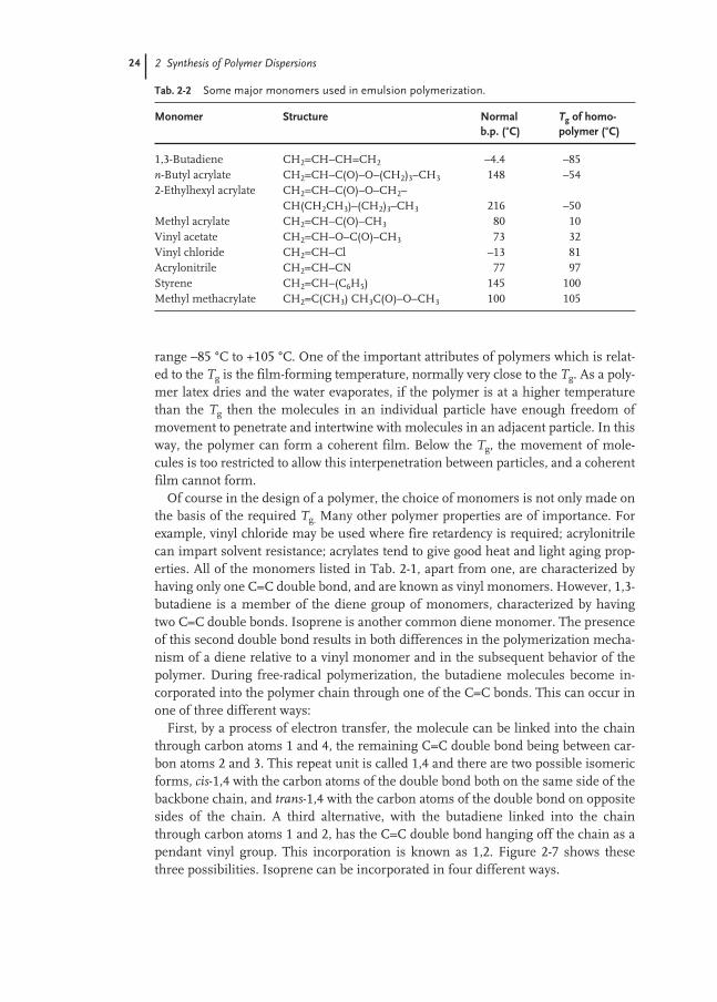
24 2 Synthesis of Polymer Dispersions
range –85 °C to +105 °C. One of the important attributes of polymers which is relat-ed to the Tg is the film-forming temperature, normally very close to the Tg. As a poly-mer latex dries and the water evaporates, if the polymer is at a higher temperaturethan the Tg then the molecules in an individual particle have enough freedom ofmovement to penetrate and intertwine with molecules in an adjacent particle. In thisway, the polymer can form a coherent film. Below the Tg, the movement of mole-cules is too restricted to allow this interpenetration between particles, and a coherentfilm cannot form.
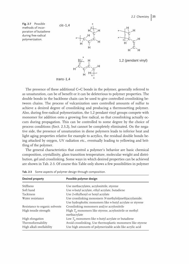
Of course in the design of a polymer, the choice of monomers is not only made onthe basis of the required Tg. Many other polymer properties are of importance. Forexample, vinyl chloride may be used where fire retardency is required; acrylonitrilecan impart solvent resistance; acrylates tend to give good heat and light aging prop-erties. All of the monomers listed in Tab. 2-1, apart from one, are characterized byhaving only one C=C double bond, and are known as vinyl monomers. However, 1,3-butadiene is a member of the diene group of monomers, characterized by havingtwo C=C double bonds. Isoprene is another common diene monomer. The presenceof this second double bond results in both differences in the polymerization mecha-nism of a diene relative to a vinyl monomer and in the subsequent behavior of thepolymer. During free-radical polymerization, the butadiene molecules become in-corporated into the polymer chain through one of the C=C bonds. This can occur inone of three different ways:
First, by a process of electron transfer, the molecule can be linked into the chainthrough carbon atoms 1 and 4, the remaining C=C double bond being between car-bon atoms 2 and 3. This repeat unit is called 1,4 and there are two possible isomericforms, cis-1,4 with the carbon atoms of the double bond both on the same side of thebackbone chain, and trans-1,4 with the carbon atoms of the double bond on oppositesides of the chain. A third alternative, with the butadiene linked into the chainthrough carbon atoms 1 and 2, has the C=C double bond hanging off the chain as apendant vinyl group. This incorporation is known as 1,2. Figure 2-7 shows thesethree possibilities. Isoprene can be incorporated in four different ways.
Tab. 2-2 Some major monomers used in emulsion polymerization.
Monomer Structure Normal Tg of homo-b.p. (°C) polymer (°C)
1,3-Butadiene CH2=CH–CH=CH2 –4.4 –85n-Butyl acrylate CH2=CH–C(O)–O–(CH2)3–CH3 148 –542-Ethylhexyl acrylate CH2=CH–C(O)–O–CH2–
CH(CH2CH3)–(CH2)3–CH3 216 –50Methyl acrylate CH2=CH–C(O)–CH3 80 10Vinyl acetate CH2=CH–O–C(O)–CH3 73 32Vinyl chloride CH2=CH–Cl –13 81Acrylonitrile CH2=CH–CN 77 97Styrene CH2=CH–(C6H5) 145 100Methyl methacrylate CH2=C(CH3) CH3C(O)–O–CH3 100 105
2.2 Chemistry 25
The presence of these additional C=C bonds in the polymer, generally referred toas unsaturation, can be of benefit or it can be deleterious to polymer properties. Thedouble bonds in the backbone chain can be used to give controlled crosslinking be-tween chains. The process of vulcanization uses controlled amounts of sulfur toachieve a desired degree of crosslinking and producing a thermosetting polymer.Also, during free-radical polymerization, the 1,2 pendant vinyl groups compete withmonomer for addition onto a growing free radical, so that crosslinking actually oc-curs during propagation. This can be controlled to some degree by the choice ofprocess conditions (Sect. 2.3.2), but cannot be completely eliminated. On the nega-tive side, the presence of unsaturation in diene polymers leads to inferior heat andlight aging properties relative for example to acrylics, the residual double bonds be-ing attacked by oxygen, UV radiation etc., eventually leading to yellowing and brit-tling of the polymer.
The general characteristics that control a polymer’s behavior are basic chemicalcomposition, crystallinity, glass transition temperature, molecular weight and distri-bution, gel and crosslinking. Some ways in which desired properties can be achievedare shown in Tab. 2-3. Of course this Table only shows a few possibilities in polymer
Fig. 2-7 Possiblemethods of incor-poration of butadieneduring free-radicalpolymerization.
CHH
CC
CH
HH
*
*H
n
CCC
H
C
HH
H
*
H
H
*
n
CH*
C
H
H C*
C
H
H H
n
cis -1,4
trans -1,4
1,2 (pendant vinyl)
Tab. 2-3 Some aspects of polymer design through composition.
Desired property Possible polymer design
Stiffness Use methacrylates, acrylonitrile, styreneSoft hand Use n-butyl acrylate, ethyl acrylate, butadieneTackiness Use 2-ethylhexyl or hexyl acrylateWater resistance Use crosslinking monomers N-methylol(meth)acrylamide.
Use hydrophobic monomers like n-butyl acrylate or styreneResistance to organic solvents Crosslinking monomers and/or acrylonitrileHigh tensile strength High Tg monomers like styrene, acrylonitrile or methyl
methacrylateHigh elongation Low Tg monomers like n-butyl acrylate or butadieneThermoformability Avoid crosslinking. Use thermoplastic monomers like styreneHigh alkali swellability Use high amounts of polymerizable acids like acrylic acid

26 2 Synthesis of Polymer Dispersions
design. There are vast numbers of different potential combinations of monomersavailable to choose from, each with variations in molecular weight, branching,crosslinking etc., giving almost infinite possibilities in the balance of properties ob-tained.
2.2.3
Functional Monomers
Certain monomers are characterized as functional monomers, so called because inaddition to having the polymerizable C=C double bond they contain a functionalgroup such as a carboxylic acid or amide. These monomers are important becausethey can impart special properties to both the polymer and the colloidal system. Theyare normally used in relatively small amounts, typically 2–5 % of the dry polymer.Table 2-4 lists some of the commonly used functional monomers. Acrylic andMethacrylic acids are the most widely used monobasic carboxylic acids, with Itacon-ic and Fumaric acids as common dibasic acids. These acids, through the C=C bond,participate in the free-radical polymerization and become incorporated in the mainpolymer, but due to the highly polar carboxyl group (COOH) tend to be at the surfaceof the polymer particles (polymer-water interface) with the carboxyl group orientatedtoward the aqueous phase. The acid group is ionized in water, so that the particlesurface has a negative charge at each acid site (–COO–). The negative charge at thesurface imparts a high degree of stability to the polymer particles, particles repellingeach other due to the like charges. This stabilizing influence is the same as that pro-duced by surfactants, but with the added advantage that the carboxylic acid is boundinto the polymer chains, not just adsorbed at the particle surface. To maintain over-all electrical neutrality across the interface, the layer of negative ions is balanced byan adjacent layer of cationic counterions. The ions and counterions are referred to asthe electric double layer and the thickness of this layer is very dependent on the pHof the continuous medium. At low pH (high H + concentration) the layer is com-pressed and at its minimum thickness. As the pH is increased (reducing H + con-centration), the layer expands outward from the particle. The thickness of this doublelayer contributes to the effective diameter of the latex particle, and is one reason forincreasing viscosity as pH increases. It should be noted that the presence of water-soluble polymer in the latex could also contribute strongly to viscosity increase withincreasing pH, due to stretching of the chains.
Tab. 2-4 Commonly used functional monomers.
Functional monomer Structure
Acrylic acid CH2=CH–C(O)–OHMethacrylic acid CH2=C(CH3)–C(O)–O–HItaconic acid CH2=C(C(O)–OH)–CH2–C(O)–O–HFumaric acid H–O–C(O)–CH=CH–C(O)–O–HHydroxyethyl acrylate CH2=CH–C(O)–O–CH2–C(OH)H2
Acrylamide CH2=CH–C(O)–NH2
2.2 Chemistry 27
In addition to the greatly enhanced mechanical stability imparted to the emulsionby these functional monomers, stability to electrolytes is generally improved, as isfiller tolerance of the latex. Mechanical strength of the polymer films is increased,and in fact can be increased further by the use of, for example zinc oxide, which givesan ionic crosslink between carboxyl groups. The presence of the carboxyl groups alsoallows crosslinking through the use of urea-formaldehyde, phenol-formaldehyde,melamine-formaldehyde and various epoxy resins. Polymerization of the acid func-tional monomers is usually carried out under conditions of relatively low pH. Neu-tralization of the acid favors partitioning in the aqueous rather than the organicphase, reducing incorporation into the polymer and at worst, where homo-polymer-ization of the acid is a possibility, as with acrylic and methacrylic acids, the formationof polyacrylic acid salts in the aqueous phase. These high molecular weight polyelec-trolytes can act as very effective coagulants for the latex.
2.2.4
Surfactants
As first discussed in Sect. 2.1.1, surface-active materials are normally an essentialingredient in emulsion polymerization. They can be used in any or all of the follow-ing roles:– micellar solubilization of monomers, forming the primary sites for nucleation– stabilization of growing polymer particles– enhancement of application properties of the finished latex
A single surfactant may satisfy all three roles, or there may be a requirement formultiple surfactants. The optimum choice of surfactant for one role may produceundesirable performance in other roles, and there may be positive or negative syner-gism exhibited when multiple surfactants are used. As with many other aspects ofemulsion polymerization, a compromise is often required in the choice of surfac-tant.
A key phenomenon observed with surfactants is a marked change in a number ofphysical properties of an aqueous solution that takes place at a certain critical con-centration. For example, with ionic surfactants, equivalent conductivity exhibits asharp reduction, surface tension reaches a minimum then begins to increase, inter-facial tension reaches a minimum and osmotic pressure almost plateaus. Below thisconcentration, surfactant molecules are in normal random solution in the water. Asthe critical concentration is reached, the surfactant molecules aggregate into orderedclusters known as micelles, normally considered to be spherical but other geometrysuch as lamellar is also possible. The break in the behavior of solution properties rep-resents the change from a true solution to a colloidal solution. The concentration ofsurfactant at which this change takes place is known as the Critical Micelle Concen-tration (CMC), and the number of molecules of surfactant which form one micelle iscalled the agglomeration number. Addition of further surfactant above the CMC allgoes toward increasing the number of micelles.
The main characteristic of a surfactant is that its molecular structure consists oftwo parts, a lyophobic (solvent hating) portion and a lyophilic (solvent loving) por-
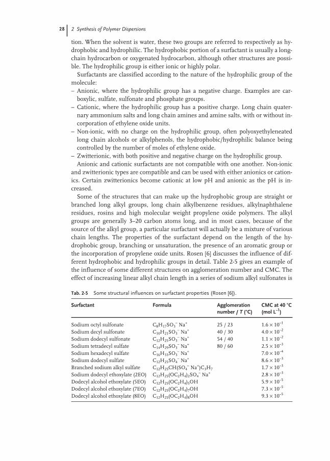
28 2 Synthesis of Polymer Dispersions
tion. When the solvent is water, these two groups are referred to respectively as hy-drophobic and hydrophilic. The hydrophobic portion of a surfactant is usually a long-chain hydrocarbon or oxygenated hydrocarbon, although other structures are possi-ble. The hydrophilic group is either ionic or highly polar.
Surfactants are classified according to the nature of the hydrophilic group of themolecule:– Anionic, where the hydrophilic group has a negative charge. Examples are car-
boxylic, sulfate, sulfonate and phosphate groups.– Cationic, where the hydrophilic group has a positive charge. Long chain quater-
nary ammonium salts and long chain amines and amine salts, with or without in-corporation of ethylene oxide units.
– Non-ionic, with no charge on the hydrophilic group, often polyoxyethyleneatedlong chain alcohols or alkylphenols, the hydrophobic/hydrophilic balance beingcontrolled by the number of moles of ethylene oxide.
– Zwitterionic, with both positive and negative charge on the hydrophilic group.Anionic and cationic surfactants are not compatible with one another. Non-ionic
and zwitterionic types are compatible and can be used with either anionics or cation-ics. Certain zwitterionics become cationic at low pH and anionic as the pH is in-creased.
Some of the structures that can make up the hydrophobic group are straight orbranched long alkyl groups, long chain alkylbenzene residues, alkylnaphthaleneresidues, rosins and high molecular weight propylene oxide polymers. The alkylgroups are generally 3–20 carbon atoms long, and in most cases, because of thesource of the alkyl group, a particular surfactant will actually be a mixture of variouschain lengths. The properties of the surfactant depend on the length of the hy-drophobic group, branching or unsaturation, the presence of an aromatic group orthe incorporation of propylene oxide units. Rosen [6] discusses the influence of dif-ferent hydrophobic and hydrophilic groups in detail. Table 2-5 gives an example ofthe influence of some different structures on agglomeration number and CMC. Theeffect of increasing linear alkyl chain length in a series of sodium alkyl sulfonates is
Tab. 2-5 Some structural influences on surfactant properties (Rosen [6]).
Surfactant Formula Agglomeration CMC at 40 °C number / T (°C) (mol L–1)
Sodium octyl sulfonate C8H17SO3– Na+ 25 / 23 1.6 × 10⁻¹
Sodium decyl sulfonate C10H21SO3– Na+ 40 / 30 4.0 × 10⁻²
Sodium dodecyl sulfonate C12H25SO3– Na+ 54 / 40 1.1 × 10⁻²
Sodium tetradecyl sulfate C14H29SO3– Na+ 80 / 60 2.5 × 10⁻³
Sodium hexadecyl sulfate C16H33SO3– Na+ 7.0 × 10⁻⁴
Sodium dodecyl sulfate C12H25SO4– Na+ 8.6 × 10⁻³
Branched sodium alkyl sulfate C12H25CH(SO4– Na+)C3H7 1.7 × 10⁻³
Sodium dodecyl ethoxylate (2EO) C12H25(OC2H4)2SO4– Na+ 2.8 × 10⁻³
Dodecyl alcohol ethoxylate (5EO) C12H25(OC2H4)5OH 5.9 × 10⁻⁵
Dodecyl alcohol ethoxylate (7EO) C12H25(OC2H4)7OH 7.3 × 10⁻⁵
Dodecyl alcohol ethoxylate (8EO) C12H25(OC2H4)8OH 9.3 × 10⁻⁵

2.2 Chemistry 29
seen, increasing carbon number giving rise to reducing agglomeration number andCMC. The sulfate group is seen to give a lower CMC than the sulfonate. Inclusion ofthe sulfate anion on a non-terminal carbon atom increases the CMC, and the intro-duction of polyethylene oxide (2 mol) into the sulfate reduces CMC. Finally, increas-ing the moles of ethylene oxide in the non-ionic series of polyoxyethyleneatedstraight chain alcohols is seen to increase the CMC.
In emulsion polymerization, anionic and non-ionic surfactants are the most com-mon choice during the polymerization stage. Cationics are used in polymerizationfor some applications, but the use of cationics and anionics in the same equipmentis generally avoided. It is possible to produce an emulsion polymer with either an an-ionic or a cationic surfactant, and subsequently switch to an oppositely chargedspecies along with a controlled pH change. Zwitterionics are not common in emulsion polymerization. If the surfactant is serving the dual purpose of providingnucleation sites and subsequently stabilizing the growing particles, balancing thetwo requirements can be difficult. For micelle formation, the concentration of surfactant must be at or above its CMC. Then, as a general rule, for a specific surfac-tant the number of polymer particles initiated is approximately proportional to [sur-factant concentration]0.6. It is therefore often the case that the amount of surfactantrequired to give the desired ultimate particle size is insufficient to provide continuedstabilization as the particles grow. This can occur almost anywhere within the nor-mal particle size range, and as a consequence it is usually necessary to add addition-al surfactant as polymerization progresses. Addition of too much surfactant duringpolymerization can, if the CMC is exceeded, cause another family of particles to beinitiated. The difficulty of balancing nucleation and stability is exacerbated by the fact that many factors influence nucleation, for example temperature, concen-tration of initiator/surfactant/electrolyte, pH and any impurities that either retard orincrease polymerization. Seeded processes significantly reduce this variation andeliminate the requirement for the initial surfactant. Overall, with seeded processes,the total amount of surfactant is often considerably less than with micellar nucle-ation.
Some common surfactants used in emulsion polymerization are:– Sodium and potassium salts of naturally occurring fatty acids (oleic, linoleic) and
rosin acids. These soaps are used in large quantities in the production of styrene-butadiene latex for both dry rubber production and latex applications. These mate-rials are only useful at pH values greater than 7, normally being used at pH 10–12.Below pH 7, the insoluble acids are precipitated, and all stabilizing function is lost.
– Salts of sulfated linear alcohols, for example sodium lauryl sulfate, are widely usedin the emulsion polymerization of functionalized styrene–butadiene polymers andmany acrylic esters.
– A range of the salts of alkylbenzene sulfonates and alkylnaphthalene sulfonates,which give improved electrolyte stability and are not subject to hydrolysis in acidmedia as are the sulfated alcohols. Sodium dodecylbenzene sulfonate is widelyused.
– Salts of alkylphosphates, usually polyoxyethyleneated.

30 2 Synthesis of Polymer Dispersions
– non-ionic surfactants in wide use in emulsion polymerization include polyoxyeth-yleneated alkylphenols and straight chain alcohols, where the length of the alkylgroup and the moles of ethylene oxide can be varied, and polyoxyethyleneatedpolypropylene glycols, block copolymers where the moles of ethylene and propy-lene oxides can be varied to adjust the hydrophilic/hydrophobic balance.This list is by no means exhaustive, there being an almost limitless choice of sur-
factants or combinations of surfactants available. From the aspect of particle stabi-lization during the emulsification process, and even to a large extent nucleation, thechoice of surfactant is usually not too critical. By far the biggest factor in the choiceof surfactant is the application performance of the final product. Unfortunately as ageneral rule, the presence of surfactant in the final dry polymer causes reduced wa-ter resistance. Also, there is a tendency for surfactant molecules to diffuse to thepolymer/air or polymer/substrate interface, where deleterious effects (cloudiness atthe surface, loss of tack, etc.) are often caused. This again demonstrates the compro-mise often necessary in emulsion polymer synthesis.
In an attempt to mitigate against migration of surfactant, there are certain prod-ucts available, known as “polymerizable surfactants”, where the molecule contains apolymerizable C=C double bond. (This is a functional monomer because it does notform micelles.) Examples are the Noigen and Hitenol series of products from Dai-Ichi Kogyo Seiyaku (polyethoxylated alkylpropenyl phenyl ethers and polyethoxylatedalkylpropenyl phenyl ether sulfates respectively).
2.2.5
Initiator Systems
The initiator system in emulsion polymerization is the source of free radicals. Thereare two major types of system used, substances which thermally decompose to pro-duce free radicals and substances which produce free radicals when part of a redoxsystem. Light or other radiation can generate free radicals, but is not widely used foremulsion polymerization.
By far the most common thermal systems are peroxy compounds; ammonium,sodium and potassium persulfate and a wide range of organic peroxides and hy-droperoxides. The rate of decomposition of these materials is usually specified by the“half-life”, defined as the time taken at a particular temperature for the concentrationof a solution of the material to reduce to one half of its initial value through thermaldecomposition. The three persulfates have a similar half-life and their effectivenessin emulsion polymerization is therefore also similar. However, the lower water solu-bility of the potassium salt makes it less commonly used than the others. Persulfatesare generally used for polymerization in the temperature range 50–100 °C, and pro-duction of free radicals takes place in the aqueous phase of the emulsion. At highertemperatures, decomposition is usually too fast to give efficient use of the free radi-cals due to radical recombination. At lower temperatures, persulfates can still beused in conjunction with a reducing agent such as sodium bisulfite.
The organic peroxides and hydroperoxides cover a wide range of half-life, and canprovide an appropriate choice for most normal polymerization temperatures. The

2.2 Chemistry 31
differing solubilities in water also determine if the free radicals are produced in ei-ther the aqueous or the monomer phase. Table 2-6 lists some of the commonly usedthermally dissociating initiators, along with their half-life. Most commonly, the per-oxides and hydroperoxides are used at lower temperatures, 0–50 °C, as a part of a re-dox system.
Often persulfates are chosen in preference to the organic peroxides because of theincrease in colloidal stability that results from the sulfate end groups on the polymerchains. On the negative side, these sulfate groups also increase the water sensitivityof dried polymer films.
The thermal decomposition of persulfate produces both sulfate and hydroxyl radi-cals, according to the mechanism:
S2O82– → 2SO4
–•
SO4–• + H2O → HSO4
– + HO•
2OH• → H2O + 1⁄2O2
It is generally accepted that the primary initiating species is the sulfate anion radi-cal, and to the extent that termination is predominantly caused by another sulfateinitiated radical species, it is expected that most polymer chains would contain twosulfur atoms. This is generally found to be the case.
An organic peroxide decomposes as follows:
ROOR → 2RO•
and the reduction of a hydroperoxide by iron(II):
ROOH + Fe2+ → RO• + HO– + Fe3+
During the nucleation stage of emulsion polymerization, the concentration of ini-tiator exerts an influence on the number of polymer particles formed. An initiatedparticle grows very rapidly as polymer is formed. As the particle increases in surfacearea, it adsorbs surfactant from solution thus reducing the possible number of mi-celles in the system. Therefore, the faster that initiation occurs, then the greater will
Tab. 2-6 A range of thermally dissociating initiators (from manufacturers’ product literature).
Substance Half-life (h)1
40 °C 50 °C 70 °C 90 °C 110 °C 130 °C 150 °C
Dicyclohexyl peroxydicarbonate 18 4.1 0.27Ammonium persulfate 192 8.4 0.55Dilauryl peroxide 50 3.2 0.29Dibenzoyl peroxide 14 1.2 0.13t-Butyl peroxybenzoate 70 6 0.7Dicumyl peroxide 23 2.3 0.26Cumene hydroperoxide 570 100 20t-Butyl hydroperoxide 520 70
1Approximate values only. pH and the presence of other components can significantly influencedecomposition
32 2 Synthesis of Polymer Dispersions
be the number of polymer particles formed before micellar surfactant is exhausted.Because the thermal decomposition of the initiator is first order with respect to itsconcentration, the higher the concentration, the greater will be the rate of radicalproduction and the shorter the initiation period. The number of polymer particlesformed is approximately proportional to the concentration of initiator to the power of0.4. As discussed in Sect. 2.2.1, the overall rate of polymerization is proportional tothe number of polymer particles, and therefore the consequent rate of polymeriza-tion is also proportional to [Initiator]0.4. However, after completion of the nucleationstage, subsequent changes in the initiator concentration (assuming a certain mini-mum) have little effect on the rate of polymerization. This is due to the fact that thenumber of particles remains fairly constant, and the average number of radicals perparticle is dependent on the environment within the particle, not the rate of radicalproduction. The molecular weight of the polymer is however influenced by the ini-tiator concentration, because, neglecting other influences, the time available for apolymer chain to grow is dependent on the rate at which free radicals enter the parti-cle. One entering radical initiates polymerization, the next normally terminates thechain. The higher the concentration of initiator, the higher the rate of production ofradicals and the higher the rate of entry of radicals into a particle. Although this ef-fect on molecular weight is significant, chain transfer agents often exerts a bigger in-fluence.
2.2.6
Other Ingredients
The use of chain transfer agents in emulsion polymerization was briefly discussed inSect. 2.2.1. As stated, the most commonly used chain transfer agents are the mer-captans (thioalcohols) RSH, although a wide range of other compounds also exert amodifying effect during polymerization, for example carbon tetrachloride, certaindisulfides, rosin acid salts, 4-vinylcyclohexene (butadiene dimer) amongst many oth-ers, which may also include impurities in other raw materials.
The effectiveness of a chain transfer agent is denoted by its transfer constant, ε,which is the ratio of rate of the chain transfer step to the propagation step:
R–M(n) • + R–SH Ks→ R–M(n)–SH + R•
R–M(n)• + M Kp→ R–M(n + 1)•
It can be shown that, neglecting all other reactions of monomer and chain transferagent, that a plot of log [S] against log [M], where [S] and [M] are the concentrationsof modifier and monomer respectively, should be a straight line with slope ε. Thislinear relationship is generally found to hold true in emulsion polymerization, butthe slope is often not equal to ε as determined from bulk polymerization. This is be-cause the rate-determining step for mercaptan consumption can often be the diffu-sion of mercaptan through the aqueous phase into the reaction zone in the polymerparticle. In general, the fewer the number of carbon atoms in the alkyl group of the
K
Ks
p
= ε
2.2 Chemistry 33
mercaptan, the closer the apparent transfer constant in emulsion polymerization be-comes to that measured in bulk (faster diffusion). This means that the shorter chainmercaptans tend to disappear more quickly than the longer chains. Thus the shortchain modifiers tend to exert a greater modifying influence during the early stages ofa batch emulsion polymerization, whereas the longer chain alkyl groups tend to bemore effective toward the end of polymerization. C12 chains often show the best bal-ance between these extremes, hence the very common use of n-dodecyl and t-dodecylmercaptans. Of course, the overall effect of the chain transfer agent can also be con-trolled by making injections at appropriate times during polymerization, or withsemi-batch reactions by having continuous (linear or non-linear) feeds of modifier.
Polymerizable cross-linking agents are often included in emulsion polymerizationrecipes, either to form cross-links during the polymerization (increasing the gel inthe polymer, or increasing the so-called “green strength”) or to form cross-links sub-sequent to polymerization, by heat application or chemical means. As previously dis-cussed, when a diene is one of the monomers in an emulsion polymerization, thesecond double bond in the diene will lead to a considerable degree of cross-linkingduring the polymer formation. In the absence of a diene, other monomers that arecommonly used to produce cross-links during the polymer formation are divinylbenzene and a range if diacrylates and triacrylates, for example butanediol diacrylateand trimethylolpropane triacrylate. These materials would normally be incorporatedat low levels, <0.1 weight percent of the monomer, so one can see that, on average,the number of cross-links introduced would be less than one per thousandmonomer units.
To introduce heat sensitivity into the polymer (cross-linking which occurs afterpolymerization, usually when a dried polymer film is heated), two commonly usedmonomers are N-methylolacrylamide and N-methylolmethacrylamide. The structureof N-methylolacrylamide is as follows:
CH2=CH–C(O)–NH–CH2–OH
Incorporation into the polymer backbone takes place through the vinyl doublebond. Cross-linking then takes place between two methylol groups.
| |CH2–CH–C(O)–NH–CH2–NH–C(O)–CH–CH2
Electrolytes, most often alkali metal phosphates or sulfates, are utilized in emul-sion polymerization systems for a variety of reasons. When present in a micelle-forming surfactant solution, electrolytes can increase the aggregation number of themicelles (the number of soap molecules per micelle). Thus with increasing elec-trolyte concentration the number of micelles is reduced, and this is an additionalmeans of controlling the number of polymer particles formed. Electrolytes are alsoused to reduce the viscosity of the polymer emulsion, especially during the polymer-ization process, an effect that is achieved through compression of the electric doublelayer. Finally, electrolytes are often used as part of a buffer system to minimize pHvariation during polymerization. High concentrations of electrolytes will generallycause de-stabilization and agglomeration of polymer particles.
34 2 Synthesis of Polymer Dispersions
It is common to include a chelating agent, normally a salt of ethylenediaminetetraacetic acid (EDTA), in emulsion polymerization recipes. Use of this compoundto chelate metal ion impurities in the system, particularly calcium, magnesium andiron, generally leads to lower coagulum levels in the final latex, and often gives moreconsistent initiation of polymerization. It is fairly common practice in the manufac-ture of emulsion polymers at higher temperatures to use untreated (non-deionized)water as the continuous media. The use of a chelating agent protects against the“hardness” salts. In low temperature systems with redox initiators, a chelating agentis often a part of the redox system, used to complex the iron component and preventprecipitation.
2.3
Manufacturing Processes
2.3.1
Types of Process
Compared with many other types of chemical manufacture, the production of emul-sion polymers is relatively simple in terms of the unit operations required. Typicallythere is a reaction stage, where the polymer is made, a purification stage to removeresidual organic volatile components, some type of filtration or screening to removeany coagulum from the latex and a final stage where post additions of other ingredi-ents may be made along with final adjustment of latex properties such as pH andsolids content. Occasionally there may be a concentration of the latex to reduce thewater content, and for some processes there may be some purification of raw mate-rials, or recovery and recycling of raw materials.
Industrial chemical processes are categorized as batch, semi-batch or continuous,and the manufacture of emulsion polymers is carried out in all these process types.The processes differ not only in equipment type and economics of operation but alsoin the specific properties imparted to the polymer and the emulsion. In a batchemulsion polymerization, all ingredients are added to a vessel, polymerization is ini-tiated and the reaction proceeds to completion over a period of time. Thus, condi-tions in the reactor gradually change from monomer + water → polymer + water,passing through all intermediate ratios of monomer/polymer.
A continuous polymerization may be carried out in a continuous, stirred-tank re-actor, where the reactants continuously enter a stirred vessel and the product contin-uously exits. Here the conditions in the reactor remain constant with time, the com-position being equal to the exit composition. There may be only one CSTR, or multi-ple CSTRs in a chain, the product from one being the feed for the next in the chain.The greater the number of CSTRs in a chain, the closer the properties approachthose from a batch reaction. A plug-flow continuous reactor is one in which the re-acting mixture passes through the reactor without any forward or backward mixing,as for example in a tubular reactor. In this type of system, at any given position in thereactor, the composition is constant with time. Distance along the reactor is equiva-

2.3 Manufacturing Processes 35
lent to time in the batch reactor. Although emulsion polymerization in a continuoustubular reactor has been the subject of much research in the past, this process is notcommonly used because of the poor degree of mixing, heavy fouling of the reactorand the difficulties of cleaning.
In a semi-batch process, only a portion of the total ingredients is added to the re-actor initially, polymerization is initiated and the remainder of the ingredients isadded over a period of time until the desired filling volume is reached. The materialis then discharged and the process repeated. In the semi-batch process, conditions inthe reactor change rapidly when the feeds start (monomer → monomer + polymer),remain relatively constant for the majority of the feed period, and change rapidlyagain when the feed stops (monomer + polymer → polymer). For safety reasons(Sect. 2.3.4) semi-batch is the preferred manufacturing process.
Figure 2-8 shows the typical progression of the monomer/polymer compositionprofile in these main process types and Fig. 2-9 is a diagrammatic representation ofthe processes.
There are novel variations of these processes in use, as are combinations of theprocesses. The reactor type and the process conditions exert large influences on theresulting properties as discussed in Sect. 2.3.2.
The product from emulsion polymerization reactors usually contains a smallamount of non-reacted monomers, along with volatile impurities from manysources. Such impurities may include a range of solvents originating from variousraw materials, dimers and co-dimers either present in monomers or formed duringthe polymerization, alcohols from hydrolysis of vinyl esters, products formed from
Fig. 2-8 Variation of monomer/polymer in different processes expressedas % conversion of added monomer: (A) batch; (B) semi-batch; (C) chain of five CSTRs; (D) continuous plug flow.
(B)
0
20
40
60
80
100
0 1 2 3 4 5 6
Time
% C
on
vers
ion
(D)
0
20
40
60
80
100
0 1 2 3 4 5 6
Distance along reactor
% C
on
vers
ion
(A)
0
20
40
60
80
100
0 1 2 3 4 5 6
Time
% C
on
vers
ion
(C)
0
10
20
30
40
50
60
70
Reactor number in chain
% C
on
vers
ion
CSTR 1
CSTR 2
CSTR 3
CSTR 4
CSTR 5

36 2 Synthesis of Polymer Dispersions
organic initiators, and a whole range of saturated and unsaturated organics comingfrom the monomers. In many cases, polymerization is taken to a high degree of con-version in the reactors (>99 %), so that the residual monomers are often <1 %. How-ever, it is normal to further polymerize this residual monomer, often using a redoxinitiator system. Because of the low monomer concentration at this stage, the rate ofpolymerization is relatively slow, and with reactor time normally being at a premiumthis “chemical stripping” is carried out in separate, lower cost equipment. Of coursemany of the organic impurities are either not polymerizable or cannot be polymer-ized under typical emulsion polymerization conditions. To remove these contami-nants, physical separation techniques are often employed. Steam distillation is themost widely used technique, either in batch strippers or in continuous processessuch as a column stripper. In some cases, solvent extraction, membrane separationor adsorption processes may be used.
Fig. 2-9 Types of process used for emulsion polymerization: (a) batch; (b) semi-batch; (c) continuous stirred tank (chain of three); (d) continuousplug flow (tubular).
a) b)
Feed Feed
Product Product
Product
Product
Feed
Feed
Final Level
Initial Level
c)
d)

2.3 Manufacturing Processes 37
The production of styrene-butadiene rubber emulsions is one case where poly-merization is deliberately stopped at a low conversion, typically 70–80 %, in order tolimit the crosslinking reaction from the pendant vinyl groups in the butadiene units.With such large amounts of residual monomer, economics force the recovery and re-cycling of both butadiene and styrene. After the polymerization stage, residual buta-diene is flashed off under vacuum, compressed, cooled and returned to the reactorfeed, and styrene is steam stripped in a column stripper, condensed and also re-turned to the reactor.
Coagulum formed during the manufacture of emulsion polymers can cause prob-lems with application processes, and although much progress has been made in theindustry to minimize these problems, (improved recipe design, better stabilizationsystems, improved control of process parameters), there still exists the need to re-move coagulum during various stages of the process. All types of filtration equip-ment are used in the industry, from simple filter bags and static screens throughwiped screens, band filters, vibrating screens, filter presses to quite complex self-cleaning filters of various types, both with and without the use of filter aids such asdiatomaceous earth. Centrifugation is also used, although with many lattices, thedensity difference between polymer and the disperse medium is too small to makethis an efficient process.
Post additions to the latex product, and final adjustments to properties such as pHand solids content are carried out usually in simple stirred tanks, although continu-ous in-line mixing may also be practiced.
2.3.2
Influence of Process Conditions on Polymer/Colloidal Properties
As shown in Sect. 2.3.1, the three main types of reaction process differ in themonomer/polymer concentration profile throughout the reaction. Because many ofthe chemical reactions occurring during emulsion polymerization, such as branch-ing, crosslinking and propagation, are competitive and dependent on the relativequantities of monomer and polymer at the reacting site, it can be seen that all ofthese will be influenced by reactor type. Branching and crosslinking are favored athigh polymer concentrations. Therefore, given the same reaction temperature, abatch process, which has the highest average monomer concentration through theprocess, will give the least branched polymer with the lowest degree of crosslinking.The opposite end of the scale is represented by a single CSTR operating at a highconversion which will tend to give a highly branched and crosslinked polymer. In-creasing the number of CSTRs in a chain will lead to a reduction in branching andcrosslinking. A semi-batch process can be operated at both ends of the scale. Withvery fast feed rates, the system is monomer flooded and the product will be close inproperties to the batch reaction. Slow feed rates (monomer starved) lead to highbranching and crosslinking. In particular, in systems containing butadiene wherethe pendant vinyl groups contribute strongly to crosslinking, the influence ofmonomer/polymer ratio is highly significant. Crosslinking increases rapidly as con-
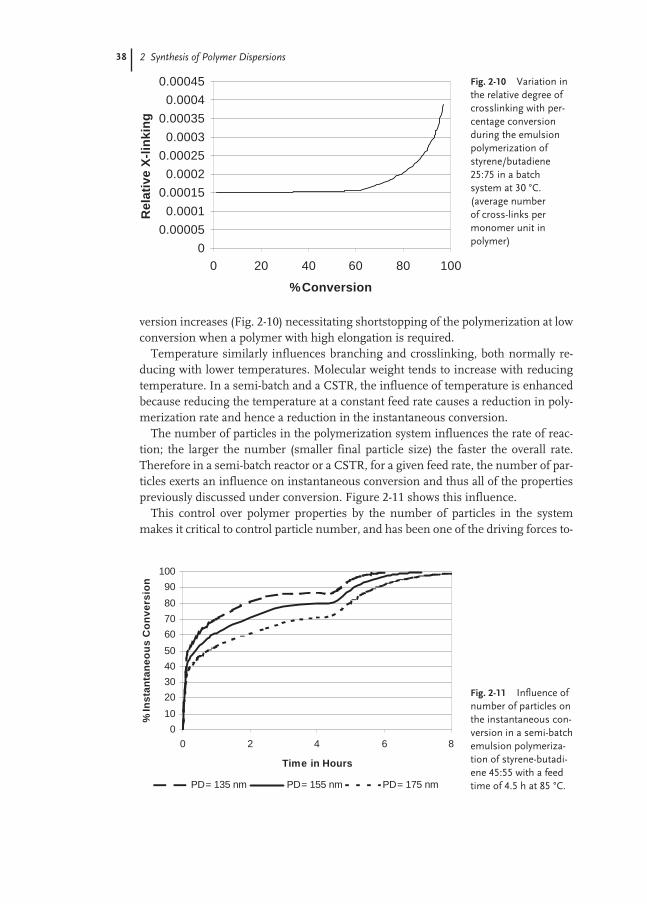
38 2 Synthesis of Polymer Dispersions
version increases (Fig. 2-10) necessitating shortstopping of the polymerization at lowconversion when a polymer with high elongation is required.
Temperature similarly influences branching and crosslinking, both normally re-ducing with lower temperatures. Molecular weight tends to increase with reducingtemperature. In a semi-batch and a CSTR, the influence of temperature is enhancedbecause reducing the temperature at a constant feed rate causes a reduction in poly-merization rate and hence a reduction in the instantaneous conversion.
The number of particles in the polymerization system influences the rate of reac-tion; the larger the number (smaller final particle size) the faster the overall rate.Therefore in a semi-batch reactor or a CSTR, for a given feed rate, the number of par-ticles exerts an influence on instantaneous conversion and thus all of the propertiespreviously discussed under conversion. Figure 2-11 shows this influence.
This control over polymer properties by the number of particles in the systemmakes it critical to control particle number, and has been one of the driving forces to-
Fig. 2-10 Variation inthe relative degree ofcrosslinking with per-centage conversionduring the emulsionpolymerization ofstyrene/butadiene25:75 in a batch system at 30 °C. (average number of cross-links permonomer unit in polymer)
0
0.00005
0.0001
0.00015
0.0002
0.00025
0.0003
0.00035
0.0004
0.00045
0 20 40 60 80 100
% Conversion
Re
lati
ve
X-l
ink
ing
Fig. 2-11 Influence ofnumber of particles onthe instantaneous con-version in a semi-batchemulsion polymeriza-tion of styrene-butadi-ene 45:55 with a feedtime of 4.5 h at 85 °C.
0
10
20
30
40
50
60
70
80
90
100
0 2 4 6 8
Time in Hours
% I
ns
tan
tan
eo
us
Co
nv
ers
ion
PD = 135 nm PD = 155 nm PD = 175 nm

2.3 Manufacturing Processes 39
ward the use of seed polymer. The use of seed reduces the variability of the nucle-ation stage, making it less dependent on temperature, surfactant concentration, elec-trolyte concentration etc. Of course this is in turn dependent upon the seed itself be-ing a consistent raw material.
2.3.3
Equipment Considerations
The reactors used for the manufacture of emulsion polymers are normally relativelysimple, agitated vessels, ranging in size from 5 m3 (less than this is normally consid-ered to be pilot plant scale) to 200 m3, with the majority being in the range15–100 m3. Carbon steel, glass-lined construction used to be the standard (the glasssurface minimizing polymer deposition) for polymerization under acid or slightly al-kaline conditions. For high pH systems (for example those based on the alkali metalsalts of fatty acids and using redox initiator systems) carbon steel reactors are thestandard. As emulsion stability has been improved over the years, and better clean-ing techniques have been developed (high pressure water jets), it has become com-mon to replace glass-lined reactors with either stainless steel or carbon steel withstainless steel cladding. Typically, to avoid contamination from metal ions, allpipework associated with feeds into and product from the reactor would be stainlesssteel construction.
Pressure ratings of reactors range from atmospheric to >100 bar with temperatureof operation in the range 5–200 °C. (in certain special cases sub-zero temperaturesmay be achieved through the use of anti-freeze agents in the emulsion). The mostcommon temperature range for emulsion polymerization is 60–100 °C.
To control the temperature of these highly exothermic reactions, reactors are fittedwith a variety of cooling systems. This may be a jacket around the reactor (annular,dimpled, half-pipe); the reactor may be fitted with internal cooling coils or cooledbaffles; there may be supplemental cooling systems such as reflux condensers, orheat exchangers of various types through which the reaction mixture is circulated.
For agitation, a wide variety of impeller types are in use; both axial and radial flowturbines, propellers, paddles, anchor agitators and many other proprietary designs.The choice of impeller is very much dependent on the properties of the emulsionpolymer being made (stability, viscosity etc.).
Latex may be transferred through subsequent parts of the process either using in-ert gas pressure or with a variety of low shear pumps. It is normal to neutralize thelatex after the reaction stage, thus greatly increasing stability. High-pressure equip-ment is not usually necessary downstream of the reactor, although some operationswill require full vacuum rating.
As discussed in Sect. 2.3.1, batch strippers, stripping columns, filtration equip-ment and mixing vessels are all in use to a varying extent downstream of the reactionstage. Because of the tendency of emulsion polymers to cause deposits in theprocess, the secret of successful operation is usually to keep equipment simple. Easeof cleaning is paramount, and “moving parts”, particularly if high shear is impartedto the latex, should be avoided where possible.
40 2 Synthesis of Polymer Dispersions
2.3.4
Safety Considerations
To carry out emulsion polymerization safely, the pressure which can develop undera worst case scenario should always be less than the design pressure of the reactor.As with any highly exothermic chemical reaction, if the generated heat is not re-moved from the system, the temperature (and in an enclosed system, the pressure)will increase in an exponential manner. The pressure can rapidly exceed the designpressure of the containing vessel, resulting in rupture of the vessel or its associatedpiping if the system is not protected by appropriate relief devices. It has to be ques-tioned whether or not relief devices are ever really appropriate – in reality, althoughthe reactor may be protected, a potentially hazardous situation is being transferredelsewhere (vent tanks, quench tanks, environment). The correct sizing of relief sys-tems for emulsion polymerization reactors is also not a trivial exercise, in part be-cause it is difficult to define a worst case scenario and in part because emulsion andpolymer properties at extreme reaction conditions are not well known. Very large re-lief devices are often indicated, which in turn means a large problem outside the re-actor.
A major driving force for the change from batch to semi-batch polymerizationprocesses, despite the loss in some polymeric properties which often accompaniesthis change, has been the inherently safer aspects of semi-batch, with smaller quan-tities of monomer in the reactor at any given time.
Thus, the major capacity limitation in the process can be seen to be a function ofthe pressure rating of the reactor, the rate and efficiency of removing heat from thesystem, and the safety systems which are in place to ensure that the maximum reac-tor working pressure can never be exceeded.
References
1 W. D. Harkins, J. Am. Chem. Soc. 1947,69, 1428.
2 W. D. Harkins, J. Polym. Sci. 1950, 5,217.
3 W. V. Smith, R. H. Ewart, J. Chem. Phys.1948, 16, 592.
4 D. C. Blackley, Emulsion PolymerisationTheory and Practice, Applied Science,1975.
5 T. G. Fox, P. J. Flory, J. Appl. Phys.1950, 21, 581.
6 M. J. Rosen, Surfactants and InterfacialPhenomena, John Wiley and Sons,1989.
7 The schematic diagram is a courtesy of C. D. Anderson, M. S. El-Aasser,Emulsion Polymers Institute, LehighUniversity, Bethlehem Pennsylvania.

41
3
Characterization of Aqueous Polymer Dispersions
Harm Wiese
3.1
Introduction
Aqueous polymer dispersions and the polymer films that form from them exhibit adiverse and complex range of properties. Moreover, these systems possess a markedheterogeneity at the mesoscopic level and their characterization is therefore a diffi-cult task. In addition to determining the macroscopic properties of the dispersion(Sect. 3.2.1), characterization requires investigating the polymer particles themselves(Sect. 3.2.2), the residual volatile content (Sect. 3.2.3) and the aqueous phase(Sect. 3.2.4). It is also important to understand the process of film formation(Sect. 3.3.1) and to be able to describe the macroscopic and microscopic properties ofthe film (Sects 3.3.2 and 3.3.3).
Given the large number of parameters and the numerous techniques employed tomeasure them, this article can only hope to provide a broad overview of this vast sub-ject area. For more detailed descriptions of the various measurement methods, thereader is referred to the literature.
Beyond the general physical and chemical characterization of dispersions andpolymer films, a large number of application-specific tests exist. In this chapter,space does not permit discussion of these tests nor of the wide variety of the formu-lations used in the different applications. Other areas which have had to be excludedare the on-line and off-line methods of monitoring emulsion polymerization [1] andtechniques for determining the microbial contamination of polymer dispersions.

42 3 Characterization of Aqueous Polymer Dispersions
3.2
Polymer Dispersions
3.2.1
General Characterization of Dispersions
Solids contentIn most of the applications the determination of the solids content is the first part ofany routine characterization of emulsion polymers, since it is the polymer and notthe water which is used in the final product.
Typically, the dispersion is dried to constant mass at a temperature of between 100and 140 °C (see, for example, ISO 1625) and the solids content is then expressed asthe percentage ratio of the dry matter to the total mass of the sample.
The dry matter comprises the polymer, emulsifiers and inorganic salts (formed bythe decomposition of the initiators and from neutralization). The volatile part in-cludes the water and monomers which were not converted during the polymeriza-tion reaction. A comparison of the theoretical solids content (that is assuming com-plete monomer conversion) to the experimental value therefore provides a means ofassessing how far polymerization has proceeded to completion.
To accelerate the drying process, most modern laboratories make use of alterna-tive drying techniques such as halogen lamps, microwaves and infrared radiators.Because of a possible thermal decomposition of the polymer or emulsifiers howeverthe temperature of the sample must not be allowed to rise much above the tempera-ture range specified above. Furthermore, the drying rate should not be too high sincethis may cause skin formation on the surface of the sample. If the skin bursts mate-rial can be lost from the sample tray.
Coagulum and gritIn many applications polymer dispersions must only contain a very small fraction ofagglomerates with diameters greater than 1 µm. Coarse components may be re-moved by filtration. Mesh sizes of between 45 and 180 µm are typical. The filterresidue is known as the coagulum content or sieve residue.
A determination of sieve residue according to ISO 4576 may involve pre-dilutingthe dispersion with water before filtering it through stainless steel filters having theabove mesh size. The residue is rinsed with water, dried and weighed. The amountof residue is expressed as a fraction of the original dispersion mass. The type of filterand the mesh size should be specified.
Fine agglomerates or large polymer particles which cannot be separated by filtra-tion but are still visible in the wet or dry polymer film are known as grit. The grit isundesirable in many applications, particularly in transparent coatings and must beprevented during the polymerization process. To characterize the fraction of gritpresent, the filtered dispersion is cast on to a glass plate using film applicators withspecified gap size (for example 45 or 125 µm). When viewed with transmitted light,grit particles can be detected by their refraction and diffraction effects. Normally, theassessment is performed on the dry film. The number of grit particles per unit area

3.2 Polymer Dispersions 43
is counted or the grit pattern classified by comparison with standard samples. Possi-ble sources of error in assessing grit content are wetting defects and occluded gasbubbles.
pH, density and surface tensionpH is an important factor in both the stabilization and the formulation of polymerdispersions. For example, dispersions that contain carboxylic acids are usually ad-justed to a pH of between 7 and 9 in order to improve their stability and to increaseviscosity. pH measurements can be performed using a standard combination elec-trode (see ISO 976). Problems however often arise due to film formation on the glassmembrane.The densities of most polymer dispersions are close to 1 g cm–3 as the correspondingpolymers (with the exception of polyvinyl chloride and poly(vinylidene chloride))have densities in the range 1.0 to 1.2 g cm–3 [2]. Since the densities of the polymerparticles almost match the density of the aqueous phase, sedimentation is usuallyonly a problem in emulsion polymers if they contain very coarse particles. Densitymeasurements have been used in the past to follow the course of emulsion polymer-ization reactions, because the density of the monomer is usually lower than that ofthe polymer (densitometry [1]). Densities can, for instance, be determined quite sim-ply with a pycnometer (see ISO 2811). Very high precision density measurements(±5 × 10⁻⁶ g cm–3) are possible with a vibrating-tube densimeter [3]. In this method,the change in the resonant frequency of the tube, which depends on its total mass, ismeasured when the dispersion is placed in it. It is essential that the sample is whol-ly free of gas bubbles.
The surface tension of a polymer dispersion is of major importance in the coatingof substrates. Good wetting of the substrate is achieved with a dispersion of low sur-face tension (Sect. 3.3.2). A general approach to obtain information on the wettingproperties of a dispersion is by measuring its surface tension in air, which is gener-ally easy to determine experimentally. As a result of the emulsifiers used in emulsionpolymerization, the surface tensions of polymer dispersions generally lie some 20 to40 units below that for water (73 mN m–1).
Surface tension measurements can be made by the Du Nouy ring method (see ISO1409), the hanging drop method or by using a stalagmometer [4]. In the latter twotechniques, the shape or volume of a drop of the dispersion as it emerges from a cap-illary is used to compute the surface tension. In the Du Nouy ring method, a thinring of platinum wire, suspended in the dispersion parallel to the surface, is with-drawn from the dispersion and the tensile force exerted by the liquid lamella that ex-tends from the ring to the bulk liquid is measured just before it ruptures. As thismethod requires relatively low dispersion viscosities (< 200 mPa s), it is often neces-sary to dilute the dispersion before measurement.
The ring method enables the static surface tension of the dispersion to be deter-mined. When polymer dispersions are applied on large-scale coating machines, it isalso important how fast the surface tension of a freshly generated surface is able todecrease. A device which permits this dynamic surface tension to be measured is themaximum bubble pressure tensiometer [5]. In this method, gas bubbles are blown
44 3 Characterization of Aqueous Polymer Dispersions
through a capillary into the dispersion. The surface tension can be calculated on thebasis of the pressure changes during bubble formation. By varying the gas speed, thedynamical processes during the growth of the surface can be accessed. It is worthnoting that the hanging drop and stalagmometer techniques are also dynamic meth-ods, because the dispersion is continuously emerging from the capillary, albeit muchmore slowly than the gas exiting the capillary in the maximum bubble pressure ten-siometer.
Flow behaviorThe flow behavior of a polymer dispersion or of its formulation is a central, and oftencritical, processing parameter [6]. Paints, for example, must be easy to apply, shouldform smooth surfaces, but should not sag when applied to a wall and should notspatter during brush application. In contrast to conventional liquids, the rheologicalproperties of dispersions with a solids content above roughly 25 % are complex andstrongly dependent upon the forces applied, developing, in certain cases, a “memo-ry” of these forces. This behavior is caused by the particle interactions that becomeapparent when the solids content is high. Apart from solids content, particle size andparticle size distribution play a crucial role. Other factors affecting flow behavior arethe electrostatic charges of the polymer particles, their surface composition and wa-ter-soluble oligomers in the aqueous phase. In practice, particle charge has only arelatively minor influence because the ionic strength of the aqueous phase is gener-ally high enough (due to the presence of ions arising from the decomposition of theinitiator and from neutralization) to restrict to a few nanometers the range overwhich the electrostatic forces are effective. Even relatively small amounts of water-soluble polymers have a pronounced influence on the flow properties of a dispersionand this fact is used in practice to adjust the viscosity of the dispersion to the desiredlevel (thickeners). In contrast to polymer solutions, molecular weight and polymercomposition do not have a significant effect on the rheology of a polymer dispersion.
A simple crude assessment of flow behavior can be achieved on-site using so-called flow cups – funnel-shaped vessels with specified orifices in their bases. Themeasurement variable is the efflux time, that is the time taken for a known volumeof dispersion to exit the cup through the orifice. It is important to be aware of the factthat a variety of cups are in use and that each type of cup produces a different effluxtime. The most common types are the ISO cups (complying with ISO 2431) and theFord cups used in the ASTM D 1200 test procedure.
The efflux time characterizes the low-shear flow behavior of a dispersion flowingunder its own weight. In many industrial applications, however, much greater shearforces are applied (for example in coating machines) and these forces often have astrong effect on the rheological properties of the dispersion (non-Newtonian behav-ior, see below). The effect of shear forces can be investigated by measuring a flowcurve with a rotational viscometer (Fig. 3-1 and ISO 3219). The dispersion is shearedin a cup by an immersed rotating cylinder (spindle). In the measurement the veloci-ty gradient (or shear rate) between the outer surface of the cylinder and the inner sur-face of the stationary cup is varied. The flow curve is the plot of the torque acting onthe cylinder (or the shear stress τ which can be derived from it) as a function of the

3.2 Polymer Dispersions 45
shear rate D. The (dynamic) viscosity is defined as the quotient of shear stress andshear rate at every point along the flow curve. As both low viscous aqueous-like andhighly viscous dispersions are used, a measurement range of between one andseveral thousand mPa s must be accessible. Because of the technical limitations ofthe shear-force transducers, different cylinder/cup sizes are usually required in or-der to cover both low-viscosity to high-viscosity dispersions. Shear rates of up toabout 1000 s–1 can be accessed with conventional rotational viscometers.
The Brookfield type of viscometer, in which one of a number of different spindletypes (RV, LV and so forth) is rotated in the sample dispersion, also enjoys wide-spread use for viscosity measurements (see ISO 2555 and 1652). The disadvantagesassociated with this type of viscometer are that the shear rate is not well defined andthat the results of measurements made using different spindle types cannot be com-pared with one another.
Figure 3-2 presents a number of τ/D and η/D curves which summarize the vari-ous phenomenological descriptions of how dispersion viscosity depends upon shearrate or time. In many cases, one observes shear thinning (viscosity decreases with in-creasing shear rate) and thixotropic behavior (viscosity falls with time at a constantshear rate). For this reason, the flow curve is recorded (as shown in Fig. 3-1) by meas-uring the shear stress both as a function of increasing shear rate and as a function ofdecreasing shear rate. The hysteresis visible in Fig. 3-1 is typical of thixotropic dis-persions.
Figure 3-3 shows a viscosity/shear rate dependence which is often observed forpolymer dispersions. In this log-log plot, an high initial plateau at low shear rates isfollowed by a region of shear thinning which leads to a lower plateau at high shearrates. Increasing the shear rate further induces a strong dilatancy and possibly alsocoagulation. The shear thinning is assumed to be caused by the onset of orderingwithin the dispersion as the polymer particles align themselves in parallel layers(Fig. 3-3). The dilatancy is thought to be the result of the temporary formation of ag-gregates which can only pass by one another with difficulty.
Fig. 3-1 Measuring a flowcurve using a rotationalviscometer.
Flow curve Rotationalviscometer
shear rate
0
shear stress τ
shear rate D
viscosity η = τ / D
shear stress

46 3 Characterization of Aqueous Polymer Dispersions
When processing dispersions, a particular viscosity is often desired both at lowand at high shear rates, and these viscosities may be very different. A key objective inthe formulation and production of polymer dispersions is therefore to adjust theshear-rate profile to meet the demands of the particular application. One way inwhich this can be achieved is by the addition of polymeric thickeners, which influ-ence the viscosity at low and at high shear rates differently depending upon theirstructure and molecular weight.
Figure 3-4 shows schematically how the viscosity of a polymer dispersion varies asa function of the volume fraction φ of the particles. The volume fraction is normal-ized to unity. In rheology it is more commonly used than the alternative solids content of the dispersion. A characteristic steep increase in the viscosity is observedas one approaches a maximum volume fraction φm. Semi-empirical expressions
Fig. 3-2 Phenomenologicalclassification of the flow behavior of polymer disper-sions (τ, shear stress; D, shearrate; η, viscosity; t, time).
Time dependence
Newtonian dilatant,shear thickng.
τ
D
η
D
η
D
η
τ
D
τ
D
τ
D
η
D
η
t
(constant shear rate)
η
t
thixotropy
rheopexy
plastic
D
η
pseudoplastic,shear thinning
Shear rate dependence
yield stress
Fig. 3-3 Typical dependence of the viscosity of a polymer disper-sion on the shear rate.
log (viscosity)
log (shear rate)
dilatancy
statisticaldistribution
shear-induced ordering
aggregation
shearthinning

3.2 Polymer Dispersions 47
exist which provide more or less reasonable approximations of the experimentalcurves. For the purposes of illustration the Dougherty–Krieger equation is repro-duced here:
(3-1)
where η0 is the viscosity of the aqueous phase.The theoretical upper limit for the maximum volume fraction φm of monodisperse
spheres is 0.74, which is the value associated with hexagonal close packing. Howev-er, the steep rise in viscosity can occur at smaller volume fractions (often at around0.55 to 0.6), depending upon the type of packing and the distance over which theinterparticle forces act. If the volume fraction is constant, decreasing particle sizeresults in a decrease in the distance between the particles and an increase in the total particle surface area. This is the reason why dispersions containing fine particles have higher viscosities than those containing coarser ones. Low viscosity athigh volume fractions can be achieved with a bimodal or broad size distributionwhere the interstitial spaces between the larger particles are filled with the smallerones.
Machine processing exposes dispersions not only to shear but also to tensilestresses (extensional flow). Because of the lack of commercially available test equip-ment, studies of the extensional flow of polymer dispersions are still in their infancy.Little use is also made of viscoelastic techniques where the sample is subjected tolow-amplitude oscillatory shear and the amplitude and phase of the oscillating stressis measured (usually as a function of the frequency of the oscillation).
StabilityThe production, transport and processing of polymer dispersions expose these mate-rials to significant degree of mechanical and thermal stress, which can lead to coag-ulation, sedimentation, phase separation or changes in viscosity. These changes aregenerally due to instabilities of the polymer particles.
To avoid these problems, polymer dispersions are routinely tested for mechanicaland storage stability and, for certain applications, also subjected to freeze-thaw cycles.After testing, any changes can be inspected visually or quantified using the methodsavailable for assessing the coagulum, the viscosity or the particle size distribution.
ηη
φφ
φ
0
2 5
1= −
−
m
m.
Fig. 3-4 Dependence of viscosity onthe particle volume fraction.
viscosity
volume fraction φ
φm
shear rate:low
high

48 3 Characterization of Aqueous Polymer Dispersions
Mechanical stability: The dispersion is subjected to intensive, defined stirring (us-ing a serrated stirring disk or rotor/stator units) as, for example in ISO 2006 wherethe sample is agitated for 10 min at 14 000 rotations min–1.
Storage stability: Accelerated testing is achieved by storing the dispersion atenhanced temperature for a particular time (for example for 15 h at 80 °C).
Freeze-thaw stability: This test provides information about the re-dispersibility of adispersion after having been frozen. The test involves subjecting the dispersion torepeated freeze-thaw cycles (for example 16 h at –20 °C followed by 8 h at + 23 °C).See, for example ISO 1147.
Stability with respect to additives: For many formulations, the stability of the disper-sion with respect to various additives, such as electrolytes, solvents, fillers and pig-ments, must be tested. The additives are added either directly or, where necessary,appropriately diluted, with any changes of the dispersion being assessed as describedabove. Testing is often conducted on diluted dispersions to permit simple visual in-spections to be carried out, though the conclusions that can be drawn from thesequalitative assessments are naturally limited.
Foaming behaviorBecause of the presence of emulsifiers, polymer dispersions tend to foam. For manyapplications (for example spray coating) foaming must be suppressed by the additionof defoaming agents. The tendency of a dispersion to foam can be assessed by anumber of application oriented methods which can be used for relative measure-ments [7]. One common method uses a graduated cylinder whose base is sealed by aporous glass frit through which gas can enter the cylinder. A known quantity of thedispersion is placed on the frit, the gas flow initiated and the height of the foam with-in the cylinder is then recorded as a function of time. Good reproducibility requirescareful temperature control and thoroughly clean cylinders and frits. An alternativeapproach is to measure the foam height after beating the dispersion within a cylin-der with a perforated plate for a set time.
3.2.2
Characterization of Polymer Particles
This chapter restricts itself to a presentation of the methods used to characterize thesize and the surface of the polymer particles. Analysis of the polymer itself or theparticle morphology is usually performed on the polymer film or on the dried parti-cles and is therefore treated later in Sect. 3.3.3.
Particle sizePolymer dispersions contain particles with diameters ranging from 10 to about1500 nm. Typically, the particle size is between 100 and 250 nm. In the majority ofapplications, particle size and particle size distribution are highly significant factorsthat determine the properties of a polymer dispersion, such as its flow behavior or itsstability (Sect. 3.2.1). Measuring particle size is thus an important element when de-veloping polymer dispersions and is also used in in-process control. A broad range of

3.2 Polymer Dispersions 49
methods are available for determining particle size [8] of which only light-scatteringand sedimentation techniques as well as modern fractionation methods will be dis-cussed here. Electron microscopy is dealt with later in Sect. 3.3.3 which discusses thecharacterization of particle and film morphology.
Light transmissionA distinctive feature of polymer dispersions is their turbidity. It is caused by light
scattering of the polymer particles due to the difference in the refractive indexes ofthe polymer (typically 1.4 to 1.6 [2]) and water (1.33), and provides a simple way ofaccessing the mean particle size in the dispersion. The link between the scatteringbehavior of a dispersion of spherical particles and their diameter is provided by Mietheory [9] and is shown in Fig. 3-5 for the relative transmission of white light throughvarious 0.01 %, w/w dispersions. Transmission increases as particle size falls or withdecreasing relative refractive index (refractive index of the polymer/refractive indexof water). If the relative refractive index is known, Fig. 3-5 can be used to determinethe mean average particle size from the observed relative light transmission. Themeasurement can be performed within a matter of seconds using a simple arrange-ment of lamp, cell and photocell detector.
For polydisperse dispersions, the measured light transmission is the inverse geo-metric mean of the relative transmissions LT1, LT2, … of the respective mass frac-tions m1, m2, …:
(3-2)
Laser light scatteringOf the many methods based on laser light scattering, dynamic light scattering
(DLS, also called quasielastic light scattering QELS or photon correlation spec-troscopy PCS) has established itself as the most important technique of measuringparticle size in polymer dispersions [10]. The measurement (Fig. 3-6) involves direct-ing a laser beam into a highly diluted sample of the dispersion and recording thescattered light impinging on a photomultiplier at a particular angle.
LT LT LTm m− − −= ⋅ ⋅ …11 2
1 2
Fig. 3-5 Relative light transmission LTof 0.01 % polymer dispersions as afunction of particle diameter for differ-ent relative refractive indexes, m.LT = transmission through water/trans-mission through dispersion (2.5 cm cu-vette, white light). m = refractive indexof the polymer/refractive index of water.
0 100 200 300 400 500 6000
20
40
60
80
100
LT / %
m =1.15m =1.20
(polystyrene)
m =1.10 (polyacrylate)
diameter / nm
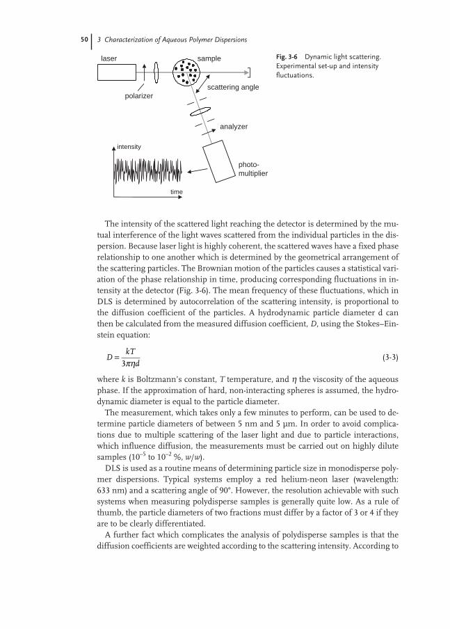
50 3 Characterization of Aqueous Polymer Dispersions
The intensity of the scattered light reaching the detector is determined by the mu-tual interference of the light waves scattered from the individual particles in the dis-persion. Because laser light is highly coherent, the scattered waves have a fixed phaserelationship to one another which is determined by the geometrical arrangement ofthe scattering particles. The Brownian motion of the particles causes a statistical vari-ation of the phase relationship in time, producing corresponding fluctuations in in-tensity at the detector (Fig. 3-6). The mean frequency of these fluctuations, which inDLS is determined by autocorrelation of the scattering intensity, is proportional tothe diffusion coefficient of the particles. A hydrodynamic particle diameter d canthen be calculated from the measured diffusion coefficient, D, using the Stokes–Ein-stein equation:
(3-3)
where k is Boltzmann’s constant, T temperature, and η the viscosity of the aqueousphase. If the approximation of hard, non-interacting spheres is assumed, the hydro-dynamic diameter is equal to the particle diameter.
The measurement, which takes only a few minutes to perform, can be used to de-termine particle diameters of between 5 nm and 5 µm. In order to avoid complica-tions due to multiple scattering of the laser light and due to particle interactions,which influence diffusion, the measurements must be carried out on highly dilutesamples (10–5 to 10–2 %, w/w).
DLS is used as a routine means of determining particle size in monodisperse poly-mer dispersions. Typical systems employ a red helium-neon laser (wavelength:633 nm) and a scattering angle of 90°. However, the resolution achievable with suchsystems when measuring polydisperse samples is generally quite low. As a rule ofthumb, the particle diameters of two fractions must differ by a factor of 3 or 4 if theyare to be clearly differentiated.
A further fact which complicates the analysis of polydisperse samples is that thediffusion coefficients are weighted according to the scattering intensity. According to
DkT
d=
3πη
Fig. 3-6 Dynamic light scattering.Experimental set-up and intensityfluctuations.
laser sample
analyzer
photo-multiplier
polarizerscattering angle
intensity
time

3.2 Polymer Dispersions 51
Mie theory, the scattering intensity of light on particles whose diameter d is approxi-mately equal to the wavelength λ of the light is a complex function of d, λ, the refrac-tive indexes of the particles and the scattering angle. This fact considerably compli-cates the calculation of the exact mass fractions. For this reason, most equipmentmanufacturers make use of simple approximate descriptions of the dependence ofscattering intensity on particle size. A more accurate approach is to measure the ab-solute scattering intensities and intensity fluctuations at a number of angles andthen to use Mie theory (assuming that the refractive indexes of the particles areknown) to convert the measured data to a particle size distribution [11].
Compared with DLS, static light scattering, in which the absolute intensity of thescattered light is analyzed as a function of scattering angle, has become less relevantas a method of determining polymer particle size. Static measurements are todaymainly used for characterizing dissolved macromolecules (with gyration radii<100 nm) and for particles with a diameter greater than 1 µm (Fraunhofer diffrac-tion). The reader is referred to the literature for further details on these tech-niques [12, 13].
CentrifugationCentrifugation methods allow a detailed and comprehensive characterization of
polymer dispersions. Figure 3-7 is a schematic view of an analytical ultracentrifuge(AUC) equipped with two types of optical detection systems (schlieren optics and tur-bidity measurement at fixed radial position, “turbidity optics”) [14]. Particle sizedetermination with an AUC exploits the different sedimentation rates of the parti-cles in the centrifugal field. According to Stokes’ law, the sedimentation time, ts, forthe path between the radial position of the meniscus, rm, and the position of the de-tection optics r (Fig. 3-7) in a centrifuge rotating at a constant angular velocity, ω, isgiven by:
(3-4)
where η is the viscosity of the aqueous phase, ρ – ρm the difference in density be-tween the particles and the aqueous phase, and d is the particle diameter. Thus par-ticle size determination requires the precise knowledge of the particle densities.
tr/r
– ds
m
m
=18
2 2
ηρ ρ ω
ln( )
( )
Fig. 3-7 Schematic diagram of an analytical ultracentrifuge (ω is the angular velocity of the rotor).
schlieren optics turbidity optics
video camera photomultiplier
laser lamp
ω
schlierenplate
samplecuvette
r
rm
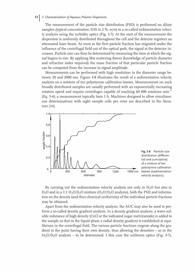
52 3 Characterization of Aqueous Polymer Dispersions
The measurement of the particle size distribution (PSD) is performed on dilutesamples (typical concentration: 0.05 to 2 %, w/w) in a so-called sedimentation veloci-ty analysis using the turbidity optics (Fig. 3-7). At the start of the measurement thedispersion is uniformly distributed throughout the cell and the detector registers anattenuated laser beam. As soon as the first particle fraction has migrated under theinfluence of the centrifugal field out of the optical path, the signal at the detector in-creases. Particle size can then be determined by measuring the time at which the sig-nal begins to rise. By applying Mie scattering theory (knowledge of particle diameterand refractive index required) the mass fraction of that particular particle fractioncan be computed from the increase in signal amplitude.
Measurements can be performed with high resolution in the diameter range be-tween 20 and 2000 nm. Figure 3-8 illustrates the result of a sedimentation velocityanalysis on a mixture of ten polystyrene calibration latexes. Measurements on suchbroadly distributed samples are usually performed with an exponentially increasingrotation speed and require centrifuges capable of reaching 60 000 rotations min–1
(Eq. 3-4); a measurement typically lasts 1 h. Machines designed to allow simultane-ous determinations with eight sample cells per rotor are described in the litera-ture [14].
By carrying out the sedimentation velocity analysis not only in H2O but also inD2O and in a 1:1 H2O:D2O mixture (H2O/D2O analysis), both the PSD and informa-tion on the density (and thus chemical uniformity) of the individual particle fractionsmay be obtained.
Apart from the sedimentation velocity analysis, the AUC may also be used to per-form a so-called density gradient analysis. In a density gradient analysis, a water-sol-uble substance of high density (CsCl or the iodinated sugar metrizamide) is added tothe sample so that in the liquid phase a radial density gradient is established at equi-librium in the centrifugal field. The various particle fractions migrate along the gra-dient to the point having their own density, thus allowing the densities – as in theH2O/D2O analysis – to be determined. I this case the schlieren optics (Fig. 3-7),
Fig. 3-8 Particle sizedistribution (differen-tial and cumulative) of a mixture of tenpolystyrene calibrationlatexes (sedimentationvelocity analysis).

3.2 Polymer Dispersions 53
which detect changes in the refractive index along the radial axis, is used for theanalysis. In contrast to the turbidity optics, a photo of the entire cell is taken onceequilibrium has been established. Normally between 10 and 20 h are needed toachieve equilibrium.
The advantage of using the schlieren optics is that in addition to the particle frac-tions also dissolved macromolecules can be studied with respect to chemical compo-sition and molecular weight. Like the polymer particles, the macromolecules migratealong the density gradient to their isodensity point. However, the small size of themacromolecules means that the bands are diffusion broadened. If the scaling lawthat relates the diffusion coefficient to the molecular weight is known, the latter canbe calculated.
The considerable amount of information obtainable by AUC analyses must beviewed in the light of the considerable technical expense and effort needed to runsuch a machine. At present, only a few laboratories have access to this technology.Disc centrifuges are a cost-effective alternative (rotation speeds of up to 15 000 rota-tions min–1).
Because of the lower rotation speeds in a disc centrifuge a different analysis tech-nique has to be employed. The cell is first filled with a spin fluid and then a samplelayer is injected on top of the fluid while the disc is rotating. By this means the parti-cle fractions migrate past the detection optics layer by layer according to their differ-ing sedimentation velocities. Unfortunately, it is often difficult to achieve a uniforminjection layer in practice (because of disruptions of the sample flow front). For thisreason, and also because of the low density difference between the polymer particlesand the aqueous phase, disc centrifuge sedimentometry is not widely used for thecharacterization of polymer dispersions.
Modern fractionation methodsIn recent years a number of new fractionation techniques, such as capillary hydro-
dynamic fractionation (CHDF) [15] and field field-flow fractionation (F-FFF) [16],have established themselves as reliable alternatives to centrifugation in PSD analy-sis. Only CHDF will be discussed here. The technique involves injecting a smallamount of the sample into an aqueous eluent containing an emulsifying agent. Theeluent is pumped through a glass capillary tubing (inner diameter 7–10 µm) and inso doing adopts a laminar flow profile (Fig. 3-9). The larger the particles, the less ablethey are to approach the capillary wall during thermal Brownian motion. Large parti-cles are therefore, on average, flowing in faster stream lines than smaller ones andare transported more rapidly through the capillary. The particle fractions are detect-ed using a UV-detector. Complications due to specific interactions between the par-ticles themselves or between the particles and the wall are eliminated by using a par-ticular type and amount of emulsifier and working at low ionic strength.
When the apparatus has been calibrated with particles of known size, the PSD of asample can be determined from its elution curve. As is the case for AUC, calculatingthe mass fractions requires application of Mie scattering theory, but this is not im-plemented in CHDF equipment currently available on the market. The manufactur-ers content themselves with a relative conversion based on the extinction coefficients

54 3 Characterization of Aqueous Polymer Dispersions
of polystyrene calibration latexes. Typically, CHDF is able to measure particle diam-eters in the range 10 to 400 nm. By using capillaries with a larger inner diameter, therange can be extended to include particles about 1 µm in diameter, but the resolutionachievable at the lower end of the particle size range is then reduced. A measure-ment takes about 10 minutes to complete.
Particle surfaceThe surface characterization of a polymer particle involves investigating the adsorp-tion of ions and amphiphilic molecules (emulsifiers, oligomers), determining thenumber of covalently bonded functional groups and acquiring information on thestructure of the interfacial layer (swollen state or ‘hairy layers’). Presently this taskcan not be solved satisfactorily. The main methods used are titrimetric analyses onpurified dispersions, soap titration and electrokinetics.
Titrimetric methodsTitrimetric analysis of polymer dispersions is mainly used to quantitatively deter-
mine acidic and basic groups covalently bonded to the particle surface (from initia-tors or comonomers). Before titration the dispersion has to be cleaned thoroughly,that is all traces of amphiphilic and ionic components have to be removed. The rec-ommended purification technique employs a combination of anionic and cationicion-exchange resin beads [17]. The beads have to be thoroughly purified themselvesbefore use.
After purification, the dispersion is titrated potentiometrically to determine thequantity of residual, that is covalently bonded, acid or base groups [17]. When titrat-ing for acids, the different pKa values enable distinction of sulfuric/sulfonic acid andcarboxylic acid. Fundamental questions that arise in connection with this methodare (1) whether all of the bonded acid groups can be neutralized because of the highresulting charge density, and (2) to what extent the particle surface reorganizes dur-ing neutralization. The increasing hydrophilicity might, for instance, cause particleswelling and a migration of acid groups from the particle interior to the surface.
Fig. 3-9 Capillary hydrodynamic fractionation (CHDF):the principle.
inaccessible regions(shown for two different particle sizes)
particle
glass capillary
parabolicflow field
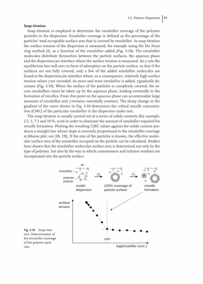
3.2 Polymer Dispersions 55
Soap titrationSoap titration is employed to determine the emulsifier coverage of the polymer
particles in the dispersion. Emulsifier coverage is defined as the percentage of theparticles’ total occupiable surface area that is covered by emulsifier. In soap titrationthe surface tension of the dispersion is measured, for example using the Du Nuoyring method [4], as a function of the emulsifier added (Fig. 3-10). The emulsifiermolecules distribute themselves between the particle surfaces, the aqueous phaseand the dispersion/air interface where the surface tension is measured. As a rule theequilibrium lies well over in favor of adsorption on the particle surface, so that if thesurfaces are not fully covered, only a few of the added emulsifier molecules arefound at the dispersion/air interface where, as a consequence, relatively high surfacetension values γ are recorded. As more and more emulsifier is added, γ gradually de-creases (Fig. 3-10). When the surface of the particles is completely covered, the ex-cess emulsifiers must be taken up by the aqueous phase, leading eventually to theformation of micelles. From this point on the aqueous phase can accommodate largeamounts of emulsifier and γ remains essentially constant. The sharp change in thegradient of the curve shown in Fig. 3-10 determines the critical micelle concentra-tion (CMC) of the particular emulsifier in the dispersion under test.
The soap titration is usually carried out at a series of solids contents (for example,2.5, 5, 7.5 and 10 %, w/w) in order to eliminate the amount of emulsifier required formicelle formation. Plotting the resulting CMC values against the solids content pro-duces a straight line whose slope is inversely proportional to the emulsifier coverageα (Maron plot, see [18, 19]). If the size of the particles is known, the effective molec-ular surface area of the emulsifier occupied on the particle can be calculated. Studieshave shown that the emulsifier molecular surface area is determined not only by thetype of polymer, but also by the way in which comonomers and initiator residues areincorporated into the particle surface.
Fig. 3-10 Soap titra-tion. Determination ofthe emulsifier coverageof the polymer parti-cles.
cmc
model dispersion
100% coverage ofparticle surface
micelle formation
surfacetension
log(emulsifier conc.)
air
emulsifier
polymerparticle

56 3 Characterization of Aqueous Polymer Dispersions
The soap titration technique is strictly only applicable for dispersions which con-tain one type of emulsifier. However, many polymer dispersions are stabilized by acombination of emulsifiers, often both ionic and non-ionic types. One approach insuch cases is to perform the study with the emulsifier mixture, though there is theproblem of exchange processes occurring on the particle surfaces if one of the emul-sifiers is preferentially adsorbed. The results may also be affected by adsorbed am-phiphilic oligomers generated during the emulsion polymerization.
ElectrokineticsElectrokinetic measurements [20] are used to access the electrophoretic mobility
µe of the polymer particles and thereby to get information on their charges. Becauseof the relatively small particle size of 100 to 250 nm, the measurement techniqueused for polymer dispersions is laser Doppler electrophoresis. Sample preparationand experimental set-up correspond to those of a dynamic light scattering experi-ment (Sect. 3.2.2, Fig. 3-6). The only difference is a pair of electrodes immersed inthe sample between which the particles are moved backwards and forwards by an al-ternating voltage.
The electrophoretic mobility, µe, is related to the zeta potential, ζ, which is definedas the electric potential at the surface of shear of the particles and is therefore ameasure of their total charge. Unfortunately, the electrophoretic mobility of disper-sion particles does not depend solely on the zeta potential, but also in a complex wayon particle size and on the ionic strength and viscosity of the aqueous phase [21]. It isonly at the limits of very high and very low ionic strength that ζ can be directly com-puted from the measured µe values (Helmholtz–Smoluchowski or Hückel approxi-mations).
These complex dependencies and some experimental difficulties (for example,due to electro-osmotic convection) are the reason why electrokinetic measurementsare still of only minor importance in the characterization of polymer dispersions. Onthe other hand, the technique provides a simple means by which the adsorption ofamphiphilic components (emulsifiers, protective colloids and so forth) on the parti-cle surfaces can be followed at least qualitatively.
3.2.3
Residual Volatiles
The increased attention paid to ecological and environmental issues in recent yearshas lead to a growing significance of residual volatile determination in polymer dis-persions. Depending upon the production process, polymer dispersions may containsmall quantities of residual monomers, monomer impurities, substances formed bythe decomposition of the initiator or from chemical reactions between the variouscomponents in the reaction mixture. The European Union has defined such sub-stances as volatiles, if they have a boiling point below 250 °C.
The determination of the residual volatiles is usually performed by capillary col-umn gas chromatography [22]. Different sampling techniques are described. In theheadspace technique (see ISO 13741-2) a diluted dispersion sample is mixed with an
3.2 Polymer Dispersions 57
internal standard and a polymerization inhibitor. The sample is then heated in asealed vial (for example at 90 °C for 1 h) and, after equilibration, a small part of theheadspace vapors is introduced into the chromatography column. In the direct liquidinjection method (see ISO 13741-1) a diluted dispersion sample is mixed with an in-ternal standard and directly injected on to the hot insert liner (temperature150–200 °C) of the chromatograph causing the dispersion to vaporize instantly. Inboth techniques the column (typically coated with a 1 µm thick layer of polydi-methylsiloxane, PDMS) is initially thermostatted at 50 °C causing the injectedvolatiles to condense at the entrance part of the column. The temperature of the col-umn is then raised linearly to 250 °C and the component substances are fractionatedby the column in the order of their volatility and detected for example by a flame ion-ization detector (FID). Careful calibration is necessary in order to assign elution timeand signal height to the type and amount of the components. With this technique,the typical residual volatiles of polymer dispersions can be quantitatively determinedin a range between 10 and approximately 10,000 ppm (measurement duration about45 minutes).
3.2.4
Aqueous Phase Analysis
In common practice the aqueous phase, or serum, of a polymer dispersion is only in-vestigated for its pH (Sect. 3.2.1). On the other hand, the aqueous phase contains ahost of substances which play an important role in many applications. These sub-stances include: (a) emulsifiers, (b) initiator residues, (c) electrolytes from the neu-tralization process or from initiator decomposition (for example sodium sulfate fromsodium peroxodisulfate), (d) unreacted water-soluble monomers such as acrylic acidor vinyl sulfonic acid, and (e) water-soluble oligomers formed from this kind ofmonomers.
To analyze the aqueous phase for any of these substances, it must first be separat-ed from the polymer particles. Both flocculation and membrane filtration techniquescan be used for this purpose and they are described in more detail below. The detec-tion of the substances listed above can then be performed with the usual array of an-alytical methods used for characterizing aqueous media. For the determination ofemulsifiers, electrolytes and water-soluble monomers, ion chromatography (IC) andhigh-performance liquid chromatography (HPLC) are particularly suitable. The tech-niques of choice for characterizing oligomers are gel permeation chromatography(GPC) and capillary electrophoresis (CE). As these analytical techniques are not spe-cific to colloidal chemistry, they will not be described further here and the readershould consult the literature for more information.
Serum separation techniques
Flocculation techniquesThe dispersion is for instance flocculated by the addition of acids or salts (typically
containing polyvalent ions). Examples of salts of this type are aluminum sulfate or
58 3 Characterization of Aqueous Polymer Dispersions
the combination of K4Fe(CN)6 and ZnSO4 (Carrez precipitation). Subjecting the dis-persion to freeze-thaw cycles also often proves successful. A further possibility iscentrifugation. If the centrifugal forces are high enough, the dispersion flocculates atthe base of the cell allowing the aqueous phase to be subsequently drawn off. In thecase of well-stabilized dispersions, high-performance centrifuges are required. Twodisadvantages of the flocculation methods should be mentioned. First, the flocculat-ed polymer particles can release considerable amounts of emulsifier into the aque-ous phase. Secondly, centrifugation may cause components in the aqueous phase tobe flocculated along with the polymer particles.
Membrane filtration techniquesIn this case, the polymer particles are separated from the aqueous phase by a
membrane through which the particles cannot permeate. Suitable membranes in-clude dialysis tubes (molecular weight cut-off: 10 000–15 000 g mol–1) or, for exam-ple, Nucleopore membranes, which are available with pore diameters from 15 nm toseveral micrometers.
In dialysis the dispersion is placed in a well-sealed tube and immersed for severaldays in water, which should be changed regularly. Before being analyzed, thedialysate usually has to be concentrated. Changing the water and concentrating thedialysate can both be carried out easily if the dialysis tube is placed inside a Soxhletapparatus.
In the diafiltration method [23], which uses the Nucleopore membranes, the dis-persion is filtered under pressure through the membrane. Like the dialysis method,diafiltration can be used not only to separate the aqueous phase, but also to ‘purify’ apolymer dispersion, that is to separate all the water-soluble components. When usedfor the latter purpose, the dispersion is continuously rinsed with water during the di-afiltration process. Filter cake formation is prevented by adopting a cross-flow filtra-tion arrangement in which, for example, a stirrer is used to create a convective cur-rent parallel to the surface of the membrane.
3.3
Polymer Films
In the typical applications such as paints, adhesives, textiles and non-wovens the dis-persions or their formulations are subjected to a drying process. The properties ofthe dispersion itself are for this reason only of relevance during processing. It is theproperties of the polymer film that are of importance to the end product, and theseproperties are essentially determined by the polymer itself. Characterizing the prop-erties of the polymer films is thus a subject of central relevance to the typical disper-sion applications.
In the description of methods presented in this chapter, the focus is on pure poly-mer films. However, these methods are equally applicable to characterizing formu-lated films such as paints.

3.3 Polymer Films 59
3.3.1
Film Formation
In the drying stage at the end of water evaporation the particles adopt a hexagonalclose-packed geometry. Good subsequent film formation requires a high level ofpolymer particle deformability and the rapid interdiffusion of polymer chains be-tween the particles. Emulsion polymers therefore possess a so-called minimum filmformation temperature (MFT), below which no compact film can be formed. The de-termination of the MFT is discussed below.
Immediately after its formation, the properties of the polymer film are still mainlydetermined by the particulate structure of the dispersion. The interstitial regions willstill house the water-soluble components (salts, emulsifiers, oligomers and so forth)and multiphase particles, for example, will initially give films with micro domains.The phases formed directly after drying are not in thermodynamic equilibrium withone another. Changes in these micro domains can occur gradually with time, or morerapidly if subjected to higher temperatures. An example of such changes is the ten-dency of the water-soluble components to group together or to migrate to the surfaceof the film. In multiphase films, the micro domains can merge to form macro domains.
The quality of a polymer film is therefore influenced not only by the properties ofthe constituent polymer, but also by the conditions under which the dispersion isdried. To achieve reproducible results when characterizing polymer films, it is nec-essary to control such parameters as wet film thickness, drying temperature, air hu-midity, air convection currents, and drying and storage times. Rapid drying, in par-ticular, can cause a skin to form on the surface of dispersion, thus hindering the con-trolled drying of the dispersion below. If low-volatility substances, such as certainfilm-forming agents, are present, thorough drying of the film is essential if the meas-urement results are to be meaningful.
To create a film with a defined (dry film) thickness of up to about 200 µm, the dis-persion is usually cast on to the substrate using either a drawdown film applicator ora roller applicator. Suitable substrates are glass, polyethylene, polyethylene tereph-thalate or teflon. Films with thicknesses in the millimeter range, such as are used formechanical strength testing, can be formed by pouring the dispersion into flexiblepolyethylene or silicone rubber trays, which facilitate the removal of the film afterdrying.
Minimum film formation temperature (MFFT)The minimum film formation temperature is determined according to ISO 2115 byspreading the dispersion at defined layer thickness (for example at 200 µm wet) on aplate along which a linear temperature gradient is established (for example from 0 to40 °C). Commercial equipment usually has shallow channels engraved in the platewhich facilitate the spreading of the dispersion. The drying has to be performed in acontrolled atmospheric environment. Once completely dry, the film is visually in-spected for the presence of cracks and cloudiness. The MFFT is the lowest tempera-ture at which a homogeneous and crack-free film forms. The MFFT is either dis-played by built-in temperature sensors or can be determined using a surface temper-
60 3 Characterization of Aqueous Polymer Dispersions
ature probe. The method also enables the so-called white-point temperature to bedetermined. This is the temperature below which a cloudy film forms and abovewhich a clear, transparent film results. The white-point temperature always lies a fewdegrees below the MFFT.
As an aqueous dispersion can only dry above 0 °C, the MFFT and white-point tem-perature are only defined above this value. The control of the polymer layer thicknessis crucial for the measurements. Mechanical stress may develop during film forma-tion (particularly when crosslinking is involved) which leads to crack formationabove a certain layer thickness. A further point which should be considered is thatvery short drying times are often used in dispersion processing, for example on coat-ing machines. In this case, the MFFT may well lie above the value determinedaccording to ISO 2115. The discrepancy is caused by kinetic limitations in waterevaporation and polymer interdiffusion [24].
The main factors determining the MFFT of an emulsion polymer are the compo-sition, molecular weight and crosslinking density of the main copolymer [24]. How-ever, particle size and the water-soluble substances such as auxiliary monomers oremulsifiers also play an important role. The effect of these substances is to retard therate at which water leaves the interstitial region. As long as the water is present themobility of the polymer chains is increased and interdiffusion thus favored. TheMFFT of a dispersion can therefore be lowered by inclusion of auxiliary monomers.In the case of multiphase polymer particles, the MFFT is strongly dependent uponmorphology. An example of this type of system are the core-shell particles withcopolymers of differing glass temperature discussed below.
3.3.2
Macroscopic Characterization of Polymer Films
Thermal characterizationThermal characterization of an emulsion polymer essentially means the measure-ment of the glass transition temperature Tg, that is the temperature above which thehard, glass-like polymer film becomes viscous or rubber-like. Polymers whose Tg lieswell above room temperature are designated as ‘hard’, those with a Tg much lowerthan room temperature as ‘soft’. Normally Tg is measured by differential scanningcalorimetry (DSC [25]). In this technique, the difference between the heat absorbedper unit time by the polymer film to that absorbed by a thermally inert reference ma-terial is recorded during a linear temperature ramp. The sample and the referenceare placed on a sensor plate of defined thermal resistance R, and the temperature dif-ference ∆T between the sample and the reference is then recorded over the tempera-ture ramp. Usually, the heat flow difference, which is the negative quotient of ∆T andR, is plotted as a function of temperature (Fig. 3-11).
Figure 3-11 is a schematic representation of a DSC measurement in which a glasstransition and a melting process are shown. A glass transition is not a second-ordertransition between two defined equilibrium states. It therefore occurs over a relative-ly wide temperature range and depends upon the rate of temperature change. Forthis reason a number of different definitions of the glass transition temperature can

3.3 Polymer Films 61
be found in the literature. The Tg shown in Fig. 3-11 is that of the so-called “mid-point” definition. The ISO 11357-1 standard specifies a heating and cooling rate ofbetween 0.5 and 20 K min–1 and recommends the repeat heating of the sample (thatis heat/cool/heat). This repeat heating helps to eliminate any influence of the ther-mal history and the drying process, for example due to the presence of residual wa-ter. Tg should always be determined during the second heating ramp. The investigat-ed temperature range, in the case of soft adhesives, should start at –110 °C and, inthe case of hard coatings, should extend to 150 °C.
Melting processes are uncommon in the emulsion polymers described in thisbook. Exceptions are the melting and crystallization phenomena observed with eth-ylene oxide chains when highly ethoxylated emulsifiers or protective colloids are em-ployed in the polymerization process.
The glass transition temperature of an emulsion polymer is the temperature abovewhich the polymer chains become mobile and it is therefore directly related to theminimum film formation temperature MFFT. In contrast to Tg, which is essentiallydetermined by the main copolymer, the MFFT is influenced by the drying process.If, for instance, water is able to solubilize part of the copolymer during the coales-cence of the particles at the end of the drying stage, the MFFT can be lowered signif-icantly. This phenomenon, which is known as “Tg/MFFT splitting”, is typical of vinylacetate emulsion polymers but also observed for other polymer types when largeamounts of hydrophilic monomers are used in the polymerization process.“Tg/MFFT splitting” is important for all applications in which a hard film with a lowMFFT is required.
Tg values of several important homopolymers are listed in reference [2]. The valueswere determined on samples of non-crosslinked emulsion polymers. In crosslinkedpolymers, Tg is shifted to higher temperatures as a result of the restricted chain mo-bility. A number of approximations for calculating the Tg of copolymers have beenproposed in the literature [26]. The Gordon–Taylor equation usually produces reli-able results:
Fig. 3-11 DSC. Investigationof glass transitions and meltingprocesses in polymer films (β, heating rate; Tg, glass transition temperature; ∆Cp, heat capacity difference of the polymer in the tempera-ture regions below and aboveTg; Tonset and Tpeak, differentdefinitions of the meltingpoint; ∆Hs, enthalpy of melting).
melting process
glass transition
heat flow difference
temperature
incr
easi
ng e
ndot
herm
icity
Tg
β∆Cp
β∆Hs
Tonset
Tpeak

62 3 Characterization of Aqueous Polymer Dispersions
(3-5)
Here m1 and m2 are the mass fractions of the monomers 1 and 2 and α is definedas ∆β(2)/∆β(1), with ∆β the difference in the coefficient of expansion of the moltenand glass states of the respective homopolymer. If α is not known, the Fox equationcan be used to provide a simple estimate:
(3-6)
For statistical copolymers, the width of the glass transition corresponds approxi-mately to that of the homopolymers. The transition broadens with increasing inhomogeneity of the monomer distribution within and between the polymerchains.
Beyond enabling the glass transition temperature to be measured, differentialscanning calorimetry also provides a simple means of investigating polymer com-patibility and phase separation in polymer films. If a film contains two phases, thisshows up as two glass transition regions in the DSC scan. The relative fraction of thephases can be determined by the ratio of the measured heat capacities. If, on the oth-er hand, the constituent polymers are wholly compatible, only one glass transition isrecorded and this lies between those of the individual components. In a similar way,the compatibility of the polymer to low molecular weight substances such as plasti-cizers can be examined.
Mechanical characterizationThe mechanical characterization of a polymer film is performed on a free film. Thisrequires drying of the dispersion on a substrate of low surface energy (such as Teflonor silicone rubber) from which it can be lifted without applying strong mechanicalforces. Great care is required when preparing such free films as defects or deforma-tions caused by mechanical stress have a detrimental effect on the reproducibility ofthe measurements. Mechanical characterization is typically performed by recordingthe stress-strain curve up until film rupture takes place (large deformations) or bydynamic mechanical analysis within the elastic limit (small deformations).
Stress-strain measurementsA stress-strain measurement on a free polymer film is performed as a uniaxial ten-
sile test. The film (typical geometry: 250 µm thick, 30 mm long and 5–10 mm wide)is loaded into a tensile testing machine and the stress (force per unit area) recordedas a function of tensile strain (elongation over original length) at a constant drawingspeed (typically 10–100 mm min–1) until the test sample ruptures [27]. Figure 3-12shows a typical form of a stress-strain diagram measured for a polymer film. Atsmall levels of deformation, the stress-strain curve is linear and the film behaveselastically. The gradient of the curve in this region is called the elastic modulus (orYoung’s modulus) of the material under test. Other parameters available from thistest are the tensile strength and the elongation at break. The integral under the curve
1 11
22T
m
T
m
Tg g g
= +( ) ( )
TT m T m
m mgg g=
++
( ) ( )11
22
1 2
αα

3.3 Polymer Films 63
to failure represents the energy per unit volume required to rupture the sample(work of fracture or toughness).
The stress-strain behavior shown in Fig. 3-12 is typical of the elastomeric responseof a polymer film. Curves of this type are found in crosslinked films above the glasstransition and in non-crosslinked films in the so-called entanglement region (seedynamic mechanical analysis below). Hard, highly crosslinked films below theirglass transition temperature are characterized by their relatively small elongation atbreak and their high tensile strength. These materials show essentially elastic be-havior up until rupture. On the other hand, non-crosslinked films (in the vicinity ofTg) are elastic at small elongations and start to deform plastically above a critical val-ue. This phenomenon is known as necking. In this case, the tensile stress passesthrough a maximum after which it remains relatively constant over a certain defor-mation range (before rising again shortly before rupture).
Stress-strain measurements are also a useful tool for studying film formation inpolymer films. Such an investigation, in which the process of polymer chain inter-diffusion in n-butyl methacrylate films was followed by monitoring the films work offracture, has been reported elsewhere [28].
Dynamic mechanical analysisIn dynamic mechanical analysis (DMA [27]) of a polymer film, a sample with the
same dimensions as in the tensile stress-strain analysis described above is slightlypre-tensioned and then subjected to a low-amplitude and low-frequency sinusoidaldeformation (typically 0.1 % and 1 Hz respectively). As the measurement is per-formed below the material’s elastic limit, the stress follows the strain in a sinusoidalmanner. The amplitude ratio and the phase difference between the stress and strainoscillations enables the dynamic elastic modulus E* to be calculated:
E* = E′ + iE″ (3-7)
where E′ is the so-called storage modulus, E″ the loss modulus and i = √––––(–1
––). E′ is a
measure of the (recoverable) energy stored in the film during deformation and E″ isthe (irrecoverable) energy that is dissipated in the film as heat.
In conventional DMA, the storage and loss moduli are recorded as a function ofthe oscillation frequency. Of more widespread application are DMA measurements
Fig. 3-12 Typical stress-straincurve for a polymer film.
work of fracture elongation at break
tensile strengthstress
strain

64 3 Characterization of Aqueous Polymer Dispersions
in which E′ and E″ are measured at a constant frequency over a temperature range.As a result of the time-temperature superposition principle, the temperature scanprovides the same information as the frequency scan. Figure 3-13 shows a typicalDMA measurement (temperature scan) on a non-crosslinked polymer film.
The storage and loss moduli can be seen to vary over several orders of magnitudeacross the temperature range. A high storage modulus is measured in the glassystate. It decreases rapidly in the glass transition region as the film softens. The lossmodulus passes through a maximum at the beginning of the glass transition region.This maximum can be used as an alternative definition of the glass transition tem-perature of the sample (compare with Sect. 3.3.2).
After passing through the glass transition region, the moduli decrease more weak-ly with temperature as a result of polymer chain entanglement and crosslinkingwithin the film. In the case of non-crosslinked polymers, a further increase in tem-perature causes the film to undergo plastic flow.
For non-crosslinked polymers, the entanglement region is only observed above acritical molecular weight (typically between 2000 and 10 000 g mol–1). This molecu-lar weight corresponds to the polymer chain length above which physical chain en-tanglement (temporary crosslinking) can occur (entanglement molecular weight).
For crosslinked polymer films, the storage and loss moduli measured above theglass transition region remain relatively constant or exhibit a slightly positive tem-perature dependence (crosslinking plateau). E″ assumes significantly lower valuesthan E′. According to the theory of rubber-elasticity, the storage and loss moduli inthis region have the following values:
E′ = 3ρRT/Mc; E″ = 0 (3-8)
where ρ is the film density, R the gas constant, T the temperature and Mc the averagemolecular weight between two crosslinking sites. Equation (3-8) shows that in thisideal case the storage modulus of a crosslinked film increases linearly with tempera-ture and provides a direct means of accessing the crosslinking density ν of the poly-mer (ν = ρ/Mc).
Fig. 3-13 Dynamic mechanicalanalysis. Storage (E′) and loss(E″) moduli as a function oftemperature for a polymer filmof poly(2-ethylhexyl methacry-late).

3.3 Polymer Films 65
When analyzing multiphase samples, it may be possible to detect several glasstransitions in a DMA measurement as was the case in the thermal characterizationof multiphase polymer films described above. DMA is also able to provide informa-tion on the effects of plasticizers, resins and fillers on the polymer film.
In the case of soft films which tend to flow it is easier to measure the dynamicshear modulus G* = G′ + iG″ than the elastic modulus E*.
The advantage is that the film is placed between two plates rather than beingclamped at its ends. G* is measured by exerting a small sinusoidal torsional dis-placement of one of the plates. The information content of the shear moduli curvescorresponds to that of the elastic moduli ones.
Optical characterizationThe transparency, gloss and color of a film are important in many applications. Thecomplete optical characterization of a polymer film would require measuring the op-tical response of the film as a function of wavelength, angles of incidence and detec-tion (relative to the surface normal), film thickness and type of substrate. Despite thefact that a multitude of optical techniques are available for such measurements (UV-visible spectroscopy, ellipsometry, laser scattering and so forth), in most applicationssimple techniques using white light are employed [29].
Film opacity is usually measured by the transmission of white light through a freefilm. The back-scattering power is determined using an integrating sphere photome-ter, that is diffuse illumination and detection of the scattered light at 0° to the filmsurface normal. Measurements of film gloss are performed by recording the intensi-ty of light reflected at a specified angle to the normal (usually 20, 60 or 85°). In color-measuring instruments, wavelength-dependent measurements are conducted atknown angles of incidence and detection and the results then converted to color val-ues. It is important to realize that when investigating films that are not whollyopaque to the wavelength concerned, the results will be influenced by film thicknessand by the choice of substrate (color, transparency and so forth). For this reason, op-tical measurements on polymer films are often performed using black foils as sub-strate (for example pigment blackened PVC).
Behavior with respect to liquidsIn a multitude of applications, polymer films get in contact with water or organicsolvents. These liquids can wet, swell, permeate or even dissolve the film. To charac-terize these processes (with the exception of wetting) simple gravimetric methodsare normally used.
WettingIf a series of liquids with increasing surface tension γL are brought into contact
with a polymer film, complete wetting will occur below a critical surface tension γC
and partial wetting (that is droplet formation) will be observed above this value (seeFig. 3-14). The critical surface tension γC is a characteristic of the polymer film and ameasure of its surface energy. Films with a high γC are easy to wet, those with a lowγC value can only be wetted with difficulty.

66 3 Characterization of Aqueous Polymer Dispersions
Wetting is quantified by measuring the contact angle, which is the angle subtend-ed by the drop at the point of contact to the film. A contact angle of 0° reflects com-plete wetting. In contrast, a value of 180° represents complete non-wetting (seeFig. 3-14). The contact angle is measured either by image analysis (sessile dropmethod) or by using a Wilhelmy balance [4, 30].
In the Wilhelmy balance method, the polymer film is suspended vertically fromthe balance and then lowered slowly until it is in contact with the liquid. If the sur-face tension at the liquid-air interface is known, the contact angle can be calculatedfrom the difference in sample weight when in and out of contact with the liquid.
The Wilhelmy method can also be used to investigate dynamic wetting processesby recording the formation of the liquid lamella in time or by immersing and with-drawing the polymer film into and from the liquid at constant rate. Time-dependentmeasurements are also useful for examining cases in which liquid is taken up afterthe polymer film has been wetted or, conversely, in which the liquid dissolves filmcomponents such as emulsifiers.
In addition to their use in determining the critical surface energy γC, contact anglemeasurements can also provide information on the polarity of the film surface. Inthis case the measurements are conducted with a series of liquids of different polar-ity (for example isopropanol-water mixtures). For evaluating the data a number of procedures have been published (see for example the Good-Girifalco-Fowkesmethod [30, 31]).
Swelling, dissolution and permeationThe usual means of characterizing swelling and dissolution processes involves
storing weighed films in the solvent of interest (for example water or tetrahydrofu-ran). After a defined period of immersion (for example 24 h), the film is removed
Fig. 3-14 Determination of the critical surface energy γC
of polymer films using the Zisman method (θ is the contact angle).

3.3 Polymer Films 67
from the liquid, liquid adhering to the surface of the film is removed and the sampleis weighed in its wet and dry state.
The percentage increase of the wet film relative to its initial weight prior to im-mersion is known as the solvent or water uptake. The weight loss of the dried filmcompared to the initial sample weight specifies the extraction loss and is due to thepartial dissolution (leaching) of film components in the liquid. Soluble and insolublefilm parts are frequently referred to as the sol and gel fractions. Measurements con-ducted for different storage periods provide information on the kinetics of the sorp-tion and dissolution processes. The speed with which the wet film dries may also beof significance for certain applications. Further parameters of interest are the vol-ume changes that accompany the swelling and the subsequent drying.
Interparticle crosslinking (that is crosslinking after film formation) reduces theswelling and dissolution of the polymer film strongly. Quantifying the solvent up-take and extraction loss is therefore a simple means for characterizing this type ofcrosslinking. In a crosslinked film, the mean molecular weight Mc between twocrosslinking sites can be calculated from by the degree of swelling in a particular sol-vent using the Flory-Huggins equation [32]:
(3-9)
where Q is the swelling ratio by volume, ρ is the polymer density, VS the molar vol-ume of the solvent and χ the Flory-Huggins interaction parameter for the polymer-solvent pair (see also Eq. 3-8).
Sorption and dissolution measurements on polymer films in various solvents arealso the basis for determining the solubility parameters of a polymer [33], which area measure of its solvent compatibility. In many applications, what is sought is thegreatest possible compatibility or incompatibility between a polymer film and a par-ticular solvent. In the case of a crosslinked polymer film, the greater the swelling thebetter the compatibility. In the case of a non-crosslinked polymer film, the greatestlevel of compatibility is achieved at the maximum solution viscosity.
Many of the methods used for the characterization of the emulsion polymermacromolecules (see Sect. 3.3.3) require the polymer film to be dissolved in a sol-vent. Full dissolution is hindered if a gel fraction is present. The gel fraction is the re-sult not only of covalent crosslinking between polymer chains, but also of the physi-cal entanglement of the chains in these high-molecular-weight emulsion polymers.The gel fraction is often higher in polymer films which have been subjected to longerdrying times as the chain segments then have the opportunity for greater interdiffu-sion.
Swelling – particularly due to the uptake of water – often creates opacity within thefilm (whitening) which is undesirable in many applications. This phenomenon iscaused by refractive index inhomogeneities created in the film when water pene-trates the interstitial regions between the particles. Characterization of film whiten-ing can be done with conventional techniques as discussed above.
The permeation of a polymer film by a liquid can be investigated by filling the liq-uid into a container whose base is made of the polymer film under test. The loss of
MV Q Q
cS=
−−
ρχ
( / )
.
/5 3 2
0 5

68 3 Characterization of Aqueous Polymer Dispersions
liquid is then recorded gravimetrically as a function of time. Such measurements areonly reproducible if pore-free films can be produced. Films can be tested for the ab-sence of pores by examining their gas tightness.
Gas permeationThe permeability of polymer films to vapors can be measured gravimetrically in anal-ogy to liquid permeability (above), with the difference that the film now acts as the lidrather than the base of a container partially filled with the liquid forming the vapor.If, rather than being filled with a liquid, the container is filled with a material whichacts as a strong absorber for a particular gas (for example sodium dihydrogen phos-phate for water vapor or sodium hydroxide for carbon dioxide), gas permeation intothe container can also be monitored. As an alternative to these gravimetric methods,conventional gas analytical techniques may be used to examine permeability, for in-stance by monitoring the pressure drop across the film or by the specific determina-tion of a gas component that permeates the film. As in the liquid permeation studies,the film samples examined must be free of pores.
3.3.3
Microscopic Characterization of Polymers
MacromoleculesMost of the methods used for the microscopic characterization of emulsion poly-mers in terms of their macromolecular composition, molecular weight andcrosslinking require the removal of water. For this reason the investigations are per-formed on the dry polymer film or on freeze-dried samples. The methods employedare the standard techniques of polymer characterization [34–36].
Some of the measurements are performed on solutions of the polymer in organicsolvents such as tetrahydrofuran or dimethylformamide. Because of their high mo-lecular weight and their partial crosslinking, complete dissolution of an emulsionpolymer is often difficult (see Sect. 3.3.2), and the information that can be providedby these methods is in such cases rather limited.
Chemical compositionThe chemical composition of an emulsion polymer sample can for instance be de-termined by Fourier transform infrared (FTIR) spectroscopy [37]. The measurementis performed on a polymer film. Quantitative analysis involves comparison of thespectra obtained with those of standard calibration substances.
An alternative or complementary method is pyrolysis gas chromatography. In thistechnique the polymer is rapidly heated causing depolymerization or decompositionand the products are separated and detected gas chromatographically [34].
Polymer composition can also be determined by 1H and 13C NMR [38] on dilutesamples of the polymer in an organic solvent. NMR analysis also enables end groupanalysis and to a limited extent monomer sequence studies (for example in terms oftriad distributions).

3.3 Polymer Films 69
In recent years there has been increased interest in using gradient HPLC tech-niques, such as gradient polymer elution chromatography (GPEC [39]), for deter-mining the compositional distribution of copolymers. The solubility gradient is cre-ated by mixing a solvent in which the polymer dissolves well with one in which itdoes not dissolve (the so-called non-solvent). The copolymer is dissolved in the goodsolvent and then injected into the LC column with the non-solvent as eluent, with theresult that the copolymer precipitates at the entrance of the column. During gradientelution, the amount of the good solvent in the eluent is gradually raised which leadsto the re-dissolution and fractionation of the copolymer.
Molecular weightThe determination of the molecular weight of the polymer is also carried out in or-ganic solution. A simple method is to measure the intrinsic viscosity [η] of the solu-tion [34]. The measurement is normally made using a capillary viscometer and in-volves recording the solution viscosity as a function of polymer concentration c andthen extrapolating the data to zero concentration (see ISO 1628-1). The dependenceof the intrinsic viscosity and the molecular weight, M, is given by the Mark-Houwinkequation:
(3-10)
where c is the polymer concentration, η0 the solvent viscosity and A and α are quan-tities which are constant at specified temperature for the solvent-polymer pair. Nor-mally, the c → 0 extrapolation is too involved for routine measurements. In such cas-es viscosity is only measured at one particular (low) concentration and used as a rel-ative measure for the molecular weight of the investigated polymer.
The Mark-Houwink equation (Eq. 3-10) assumes that the polymer in solution ispresent in the form of random statistical coils. For a given molecular weight, branch-ing and crosslinking in the macromolecule lead to a lower viscosity. In doubtful cas-es, alternative methods of absolute molecular weight characterization (static lightscattering, density gradient analysis in an analytical ultracentrifuge, membrane os-mometry, end-group analysis, and so forth) should be used for comparison purpos-es [34–36]. A modern alternative is that of matrix-assisted laser desorption ionizationmass spectrometry (MALDI MS [40]). In this technique the polymers are embeddedin a matrix made of a strong UV absorber which enables the unfragmented ioniza-tion of the macromolecules by a UV laser pulse. Absolute molecular weight determi-nation is achieved in this mass spectrometer by time-of-flight measurement.
Because emulsion polymers are prepared by a radical polymerization process, themolecular weight distribution (MWD) is generally quite broad. MWD is usually char-acterized by gel permeation chromatography (GPC, also referred to as SEC, size ex-clusion chromatography). GPC fractionates a polymer solution according to coil sizeby passing it through a micro-porous gel with a defined pore size distribution [34]. Inaddition to simple UV and refractive index detectors, other techniques such as FTIRspectrometry and light scattering are now used to characterize the individual frac-tions as they elute from the column. The latter two detectors enable both the chemi-
[ ] lim ( )ηη η
ηα=
−
=→c c
AM0
0
0
1 c
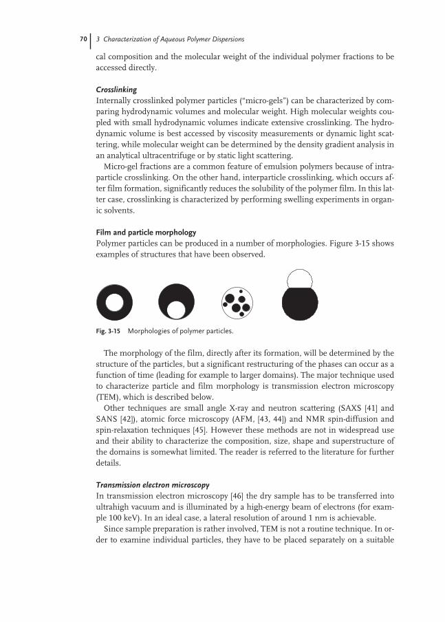
70 3 Characterization of Aqueous Polymer Dispersions
cal composition and the molecular weight of the individual polymer fractions to beaccessed directly.
CrosslinkingInternally crosslinked polymer particles (“micro-gels”) can be characterized by com-paring hydrodynamic volumes and molecular weight. High molecular weights cou-pled with small hydrodynamic volumes indicate extensive crosslinking. The hydro-dynamic volume is best accessed by viscosity measurements or dynamic light scat-tering, while molecular weight can be determined by the density gradient analysis inan analytical ultracentrifuge or by static light scattering.
Micro-gel fractions are a common feature of emulsion polymers because of intra-particle crosslinking. On the other hand, interparticle crosslinking, which occurs af-ter film formation, significantly reduces the solubility of the polymer film. In this lat-ter case, crosslinking is characterized by performing swelling experiments in organ-ic solvents.
Film and particle morphologyPolymer particles can be produced in a number of morphologies. Figure 3-15 showsexamples of structures that have been observed.
The morphology of the film, directly after its formation, will be determined by thestructure of the particles, but a significant restructuring of the phases can occur as afunction of time (leading for example to larger domains). The major technique usedto characterize particle and film morphology is transmission electron microscopy(TEM), which is described below.
Other techniques are small angle X-ray and neutron scattering (SAXS [41] andSANS [42]), atomic force microscopy (AFM, [43, 44]) and NMR spin-diffusion andspin-relaxation techniques [45]. However these methods are not in widespread useand their ability to characterize the composition, size, shape and superstructure ofthe domains is somewhat limited. The reader is referred to the literature for furtherdetails.
Transmission electron microscopyIn transmission electron microscopy [46] the dry sample has to be transferred intoultrahigh vacuum and is illuminated by a high-energy beam of electrons (for exam-ple 100 keV). In an ideal case, a lateral resolution of around 1 nm is achievable.
Since sample preparation is rather involved, TEM is not a routine technique. In or-der to examine individual particles, they have to be placed separately on a suitable
Fig. 3-15 Morphologies of polymer particles.

3.3 Polymer Films 71
substrate under conditions which prevent film formation (that means high dilutionof the sample and drying below the minimum film formation temperature). For theTEM inspection of a polymer film a thin section containing only one particle layer isrequired (typical thickness <100 nm). The thin-cut can only be done at a temperaturebelow the glass transition temperature of the polymer. Sometimes it is also possibleto directly deposit a particle monolayer on a substrate by drying the dispersion at theright dilution.
Transmission electron micrographs directly show the size and shape of the indi-vidual polymer particles. However, to draw any reliable conclusions on the distribu-tion of particle size or shape the laborious counting of a large number of particles isrequired (>1000!).
A fundamental problem of using electron microscopy to analyze polymer samplesis their low electron density, which causes low contrast in the images. Improved con-trast can be achieved by staining the polymer with heavy-metal compounds such asRuO4, OsO4 or uranyl acetate. These compounds are incorporated into the polymernetwork directly or via a suitable coupling agent.
Staining agents which exhibit high selectivity for certain polymers also form thebasis of morphology studies. For example, polystyrene and polybutadiene can be se-lectively stained with RuO4. Acrylates, on the other hand, require treatment with hy-drazine and OsO4. A core-shell particle with a polystyrene core and an acrylate shellcan thus be characterized by staining the core with RuO4. In the same way a possiblephase restructuring taking place in the film of these particles can be studied.
An alternative to the above preparation methods, albeit a rather involved one, isthe freeze-fracture technique, in which the dispersion is shock frozen by beingpoured into liquid nitrogen. The freezing process has to be fast enough to avoid crys-tallization of the water phase. The sample is then cryo-transferred to the electron mi-croscope where it is fractured. The fracture surfaces can then be imaged using, forexample, replica techniques.
AcknowledgmentsI wish to thank Dr J. Lamprecht, Dr W. Mächtle, Dr A. Zosel, Dr H. Nissler,Dr R. Baumstark, H.-J. Heiter, and S. Krause for their assistance in the preparationof the manuscript.
72
References
1 W.-D. Hergeth in: Polymeric Dispersions:Principles and Applications, J. M. Asua(ed.), Kluwer Academic Publishers, The Netherlands, 1997, pp. 267–288.
2 E. Penzel in: Ullmann's Encyclopedia ofIndustrial Chemistry, Vol. 21, VerlagChemie, Weinheim, 1992, pp. 157–178.
3 R. S. Davis, W. F. Koch in: Physical Meth-ods of Chemistry, Vol. VI: Determination ofThermodynamic Properties, B. W.Rossiter, R. C. Baetzold (eds), Wiley,New York, 1992, pp. 59–62.
4 A. W. Adamson, Physical Chemistry ofSurfaces, Wiley, New York, 1990.
5 V. B. Fainerman, R. Miller, P. Joos, Colloid Polym. Sci. 272, 731 (1994).
6 E. J. Schaller in: Emulsion Polymerizationand Emulsion Polymers, P. A. Lovell, M. S. El-Aasser (eds), Wiley, New York,1997, pp. 437–466.
7 J. J. Bikerman, Foams, Springer, Berlin,1973.
8 E. A. Collins in: Emulsion Polymerizationand Emulsion Polymers, P. A. Lovell, M. S. El-Aasser (eds), Wiley, New York,1997, pp. 385–436.
9 C. Bohren, D. Huffman, Absorption andScattering of Light by Small Particles, Wiley, New York, 1983.
10 W. Brown (ed.), Dynamic LightScattering, Oxford University Press, Oxford, 1992.
11 C. Wu, K. Unterforsthuber, D. Lilge, E. Lüddecke, D. Horn, Part. Part. Syst.Charact. 145–149 (1994).
12 P. Kratochvil, Classical Light Scatteringfrom Polymer Solutions, Elsevier, Amster-dam, 1987.
13 H. G. Barth, Modern Methods of Particle-Size Analysis, Wiley, New York, 1984.
14 W. Mächtle in: Analytical Ultracentrifuga-tion in Biochemistry and Polymer Science,S. E. Harding, A. J. Rowe, J. C. Horton(eds), Royal Society of Chemistry, Cambridge, 1992, pp. 147–175.
15 J. G. DosRamos, C. A. Silebi, J. ColloidInterface Sci. 135, 165 (1990).
16 A. M. Botana, S. K. Ratanathanawongs,J. C. Giddings, J. Microcolumn Sep. 7, 395(1995).
17 J. W. Vanderhoff, H. J. Van den Hul,R. J. M. Tausk, J. T. G. Overbeek in:Clean Surfaces, G. Goldfinger (ed.),Marcel Dekker, New York, 1970.
18 S. H. Maron, M. E. Elder, I. N. Ule-vitch, J. Colloid Sci. 9, 89 (1954).
19 J. G. Brodnyan, G. L. Brown, J. Colloid.Sci., 15, 76 (1960).
20 R. J. Hunter, Zeta Potential in ColloidScience, Academic Press, London, 1981.
21 R. J. Hunter, Foundations of Colloid Science, Vol. II, Clarendon Press, Oxford, 1989, Chapter 13.
22 Gas Chromatography, J. P. Baugh (ed.),Oxford University Press, Oxford, 1993.
23 S. Ahmed, M. S. El-Aasser, G. H.Pauli, G. W. Poehlein, J. W. Vander-hoff, J. Colloid Interface Sci. 73, 388(1980).
24 P. M. Lesko, P. R. Sperry in EmulsionPolymerization and Emulsion Polymers,P. A. Lovell, M. S. El-Aasser (eds), Wiley, New York, 1997, pp. 619–655.
25 V. B. F. Mathot (ed.), Calorimetry andThermal Analysis of Polymers, Hanser,Munich, 1994.
26 H. F. Mark, N. M. Bikales, C. G. Over-berger, G. Menges, J. I. Kroschwitz(eds) Encyclopedia of Polymer Scienceand Engineering, Vol. 7, Wiley, NewYork, 1987, p. 539.
27 I. M. Ward, Mechanical Properties ofSolid Polymers, Wiley, New York, 1983.
28 A. Zosel, G. Ley, Macromolecules 26,2222 (1993).
29 J. V. Koleske (ed.), Paint and CoatingTesting Manual, ASTM manual series,MNL 17, ASTM, Philadelphia, 1995,Chapters 40–42.
30 P. C. Hiemenz, Principles of Colloid and Surface Science, Marcel Dekker,New York, 1986, Chapter 6.
31 W. D. Bascom, Adv. Polym. Sci. 85, 89(1988).
32 P. J. Flory, Principles of Polymer Chemistry, Cornell University Press,Ithaca, 1953.
33 A. F. M. Barton, CRC Handbook of Solubility Parameters and Other Cohesion Parameters, CRC Press, Boca Raton, 1983.
References 73
34 C. Booth, C. Price (eds), ComprehensivePolymer Science, Vol. 1, Polymer Charac-terization, Pergamon Press, Oxford,1989.
35 B. J. Hunt, M. I. James (eds), PolymerCharacterization, Blackie, London, 1993.
36 E. Schröder, G. Müller, K.-F. Arndt, Polymer Characterization, Hanser, Munich, 1988.
37 D. O. Hummel, Atlas of Polymer andPlastics Analysis, Vol. 1, Polymer: Structures and Spectra, Verlag Chemie,Weinheim 1978.
38 J. L. Koenig, Spectroscopy of Polymers,ACS Professional Reference Book,American Chemical Society, Washing-ton, 1992.
39 G. Glöckner, Gradient HPLC of Copoly-mers and Chromatographic Cross-Fraction-ation, Springer, Berlin, 1991.
40 H. S. Creel, Trends Polym Sci. 1, 336(1993).
41 R. Grunder, G. Urban, M. Ballauff, Colloid Polym. Sci. 271, 563 (1993).
42 R. H. Ottewill in: Polymeric Dispersions:Principles and Applications, J. M. Asua(ed.), Kluwer Academic Publishers,The Netherlands, 1997, pp. 229–242.
43 J. Didier, Y. Wang, J. Lang, O. Leung,M. C. Goh, M. A. Winnik, J. Polym. Sci:Part B: Polym. Phys. 33, 1123 (1995).
44 S. Akari, D. Horn, W. Schrepp, Adv.Mater. 7, 549 (1995).
45 K. Landfester, C. Boeffel, M. Lambla,H. W. Spiess, Macromolecules 29, 5972(1996).
46 L. C. Sawyer, D. T. Grubb, Polymer Microscopy, Chapman and Hall, London, 1987.

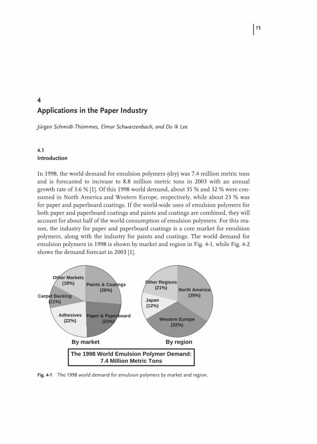
75
4
Applications in the Paper Industry
Jürgen Schmidt-Thümmes, Elmar Schwarzenbach, and Do Ik Lee
4.1
Introduction
In 1998, the world demand for emulsion polymers (dry) was 7.4 million metric tonsand is forecasted to increase to 8.8 million metric tons in 2003 with an annualgrowth rate of 3.6 % [1]. Of this 1998 world demand, about 35 % and 32 % were con-sumed in North America and Western Europe, respectively, while about 23 % wasfor paper and paperboard coatings. If the world-wide uses of emulsion polymers forboth paper and paperboard coatings and paints and coatings are combined, they willaccount for about half of the world consumption of emulsion polymers. For this rea-son, the industry for paper and paperboard coatings is a core market for emulsionpolymers, along with the industry for paints and coatings. The world demand foremulsion polymers in 1998 is shown by market and region in Fig. 4-1, while Fig. 4-2shows the demand forecast in 2003 [1].
Fig. 4-1 The 1998 world demand for emulsion polymers by market and region.
Paints & Coatings(26%)
Paper & Paperboard(23%)
Adhesives(22%)
Carpet Backing(11%)
Other Markets(18%)
North America(35%)
Western Europe(32%)
Japan(12%)
Other Regions(21%)
By market By region
The 1998 World Emulsion Polymer Demand:7.4 Million Metric Tons

76 4 Applications in the Paper Industry
This chapter will cover the applications of emulsion polymers in the paper indus-try, especially in surface sizing and paper coating. Since information on the break-down in the uses of emulsion polymers for surface sizing and paper coating is notreadily available in the world markets, it is hoped that information available on theWestern Europe market would provide some perspectives on their relative uses ofemulsion polymers. Table 4-1 shows the amounts of emulsion polymers used forthese applications in Western Europe: 3 % and 97 %, respectively [2].
4.2
The Paper Industry
4.2.1
History
The precursors of paper were papyrus and parchment, which were used for writingas early as 3000 BC in Egypt. In China, strips of bamboo or wood were used for writ-ing and drawing before the discovery of paper. The invention of paper has been at-tributed to Ts’ai Lun in AD 105, who produced a uniform writing-material paperfrom felted plant fibers [3]. The original paper was made in China from rags, bark
Fig. 4-2 The 2003 world demand forecast for emulsion polymers by market and region.
Paints & Coatings(26%)
Paper & Paperboard(24%)
Adhesives(23%)
Carpet Backing(10%)
Other Markets(17%)
North America(34%)
Western Europe(31%)
Japan(11%)
Other Regions(24%)
By market By region
The 2003 World Emulsion Polymer Demand Forecast:8.8 Million Metric Tons
Tab. 4-1 The Western European market for emulsion polymers in thepaper industry [2].
Market segment Amount of polymer dispersions in metric tons and percent (1997)
Surface sizing 35 000 ( ~3 %)Paper coating 1 150 000 (~97 %)Total 1 185 000
4.2 The Paper Industry 77
fiber, and bamboo. The plants were crushed in mortars and water was added to cre-ate a homogeneous fiber pulp. By dipping a hand wire screen into the suspension, athin layer of the pulp was removed and then dried. Even today, these are still the fun-damental steps in the papermaking process. The art of papermaking finally reachedCentral Asia by AD 751 and Baghdad by 793, and by the 14th century there werepaper mills in several parts of Europe [4]. Later, it landed in the New Continent.
With the invention of the printing press by J. Gutenberg in the middle of thefifteenth century, paper assumed a previously unimagined importance and therewas a massive increase in the demand for paper. As a result of further discoveries,increasing levels of trade and for other reasons, the level of paper consumption con-tinued to rise. Numerous raw materials were used for paper manufacture and therewere rapid developments in industrial papermaking with the first papermaking ma-chine being built in 1799. Nicholas-Louis Robert constructed the first papermakingmachine. Using a moving screen belt, paper was made one sheet at a time by dip-ping a frame or mold with a screen bottom into a vat of pulp. A few years later, thebrothers Henry and Sealy Fourdrinier improved Robert’s machine, and in 1809 JohnDickinson invented the first cylinder machine [4].
4.2.2
The Paper Industry Today
In 1998, the world production of paper and paperboard excluding newsprint and tis-sue totaled approximately 240 million metric tons and is expected to grow to approx-imately 290 million metric tons in 2003 with an annual growth rate of 4 % [1].
The main raw material used to make paper is wood. Both softwoods (long fiber)and quick-growing hardwoods (short fiber) are processed.
The intermediate stage between the raw materials and the finished paper is so-called half stuff (pulp). Typically, this is:– Cellulose from which lignin, resins, and incrustations have been removed by the
refining process to leave high-grade cellulose fiber that is particularly well suited topaper manufacture.
– Mechanical pulp, which is produced from wood that has been ground or refinedby mechanical means. This type of pulp is less well suited for paper manufacture,as the incrustations are still present to a large extent and the properties of the pulpare determined by fiber bunches and fragments inevitably present.
– Paper made of pure cellulose is designated as “wood-free” paper, whereas thatmade from mechanical wood is called “wood-containing” paper.In an effort to protect wood resources, large amounts of recycled papers are also
used in today’s papermaking industry. Modern technology combined with appropri-ate process chemicals enables this secondary raw material to be used not only for pa-perboard, but also for high-quality paper.
The proportion of the chemical additives used as fillers in both paper and coatingsis about 3 %, a surprisingly small amount compared to the other constituents suchas recycled paper, cellulose, and pigments. Of this 3 %, synthetic additives compriseonly about one third so that overall synthetic additives make up only about 1 % of the

78 4 Applications in the Paper Industry
total content (Fig. 4-3). The two most important groups of the synthetic additives arethe synthetic binders (50 %) and the sizing agents (25 %), as shown in Fig. 4-4. Whilesynthetic binders are composed of emulsion polymers, sizing agents can bemonomeric or polymeric. In the latter case, they are in the form of polymer disper-sions.
The pulp is prepared for the paper machine in an upstream unit. In this unit, thewood is ground, washed, and sorted, and then fiber concentration and consistencyare adjusted to the desired levels.
The paper machine itself is a single continuous production line with a length thattoday may exceed 200 m and comprises the following main sections: headbox, wiresection, pressing section, drying section, and finishing section.
Fig. 4-3 The proportion of chemical additives relative to the total globalraw material demand of the paper industry in 1996.
Syntheticchemicaladditives
Alum
Starch
Chemical pulp
Waste paper
Pigment/Filler
Mechanical pulp
Chemical additives
8%
35%
3%
43%
11%
1.0%
0.5%
1.5%
Fig. 4-4 Process chemicals used in the papermaking.
Additives relevant tomanufacturing process(Process chemicals)
Additives relevant to paperproperties(Functional chemicals)
Synthetic binders(Paper coating)
Dyes, OBA
Bleaching chemicals
Wet strength resins
Sizing agents
Retention drainage aids, curing agents, flocculants,etc.
BiocidesDefoamers, deaeratorsDispersants, cleaners
3%6%
8%25%
8%
50% 1%
1%
1%
5%
4.3 Surface Sizing 79
In the headbox, the pulp suspension is spread across the entire width of the weband passed onto the wire mesh at the correct speed. The sheet is formed as the waterdrains from the mesh and the fibers are fixed into their final orientation while still inthe wet mat stage. In the pressing section, water is driven out of the wet mat by ap-plying pressure to the web. The web enters the pressing section with a dry content ofabout 20 % which increases to 40–50 % as the web leaves this section of the machine.On passing through the drying section, the web is dried to a final moisture contentthat is in equilibrium with the ambient air. The drying section is often equipped withadditional devices which improve the surface properties of the paper or board. Ex-amples of such devices are the size press, the machine calendering cylinder, varioustypes of calenders, and coating equipment. The paper or board web is wound onto rollsin the finishing section which also contains roll handling and wrapping equipment.
The size of today’s paper production lines is enormous. The state-of-the-art paper-making and finishing machines are up to 10 m wide in web widths and up to2000 m min–1 (120 km h–1) in production speeds. A wide range of production andfinishing processes guarantees that even the most demanding quality requirementscan be met.
The largest part of the papers produced today is for printing, also known as graph-ic arts, i.e. for printing paper and board. The requirements that these materials mustmeet include:– high degree of uniformity and smoothness– good optical properties of which brightness and gloss are the most important– high opacity and high strength
In short, the physical characteristics of the paper or board must ensure both goodprocessability and good printability.
To meet these demands, the following two processing stages are incorporated intothe drying section of the papermaking line:– surface sizing– paper coating
The use of emulsion polymers in the paper industry is essentially restricted tothese two processes which are described in more detail in the following sections.
4.3
Surface Sizing
Surface sizing means a pigment-free application of hydrophobicizing substances,the surface sizing agents, in combination with starch. The application will be on-lineto the paper machine by either a size press or a film press. In relation to the papermass usually 3 to 5 % (w/w) of starch and 0.1 to 0.25 % (w/w) of sizing agents, eachcalculated as solid, will be applied. So in a size press formulation starch clearly dom-inates with more than 95 % of the solids content. Starch enhances the strength of thepaper, the surface sizing agent hydrophobicizes the paper sheet, thereby reducingthe absorbency of the paper. Thus, the penetration and spreading of print colors arecontrolled and the loss of strength in the wet state is reduced.

80 4 Applications in the Paper Industry
An alternative to surface sizing is internal sizing, the addition of a sizing agent tothe wet end before the formation of the paper sheet. In this process step, however,exclusively low molecular weight sizing agents like rosin acids or alkyl ketene dimers(AKD) are applied.
For surface sizing, mostly polymeric sizing agents are used. The most importantproduct classes are acrylic copolymer dispersions stabilized by protective colloids.The particles of the sizing agent consist of a hydrophobic polymer core and a hy-drophilic shell formed out of the protective colloid (Fig. 4-5).
The composition of the polymeric core influences hydrophobicity, glass transitiontemperature, viscous flow, and binding strength of the polymer. The hydrophilicshell is highly swollen in water and normally carries either an anionic or cationiccharge. It renders stability to the dispersions during storage and against the highshear stress during application. It also plays an important role in the interaction be-tween starch and sizing agent. The hydrophobic effect of surface sizing stems fromthe formation of a stable coherent film at the paper surface providing a halftone-likescreen (raster) formed from well defined hydrophobic barriers and areas of hy-drophilic character (Fig. 4-6). Polymer particles sitting at the interphase betweenstarch film and fiber surface support the fixation of the starch film to the fiber. Poly-mer particles in the interior improve the wet strength and delay the dissolution ofstarch and the flow of aqueous media within the starch layer. Polymer particles at thesurface reduce the wettability of the surface. Only dispersions stabilized by protectivecolloids are able to form such a coherent hydrophilic/hydrophobic raster. The pro-tective colloid tightly fixed to the polymer core acts as a compatibilizer betweenstarch and hydrophobic polymer core, preventing a rupture of the film during dryingand shrinking of the starch.
Fig. 4-5 Structure of a polymer-based sizing agent.
70 - 200 nm
Hydrophobic core
+
+
+
+
++
+
+
+
+
+
+
+
+
+
Charged hydrophilicprotective colloid
Charged hydrophilicprotective colloid
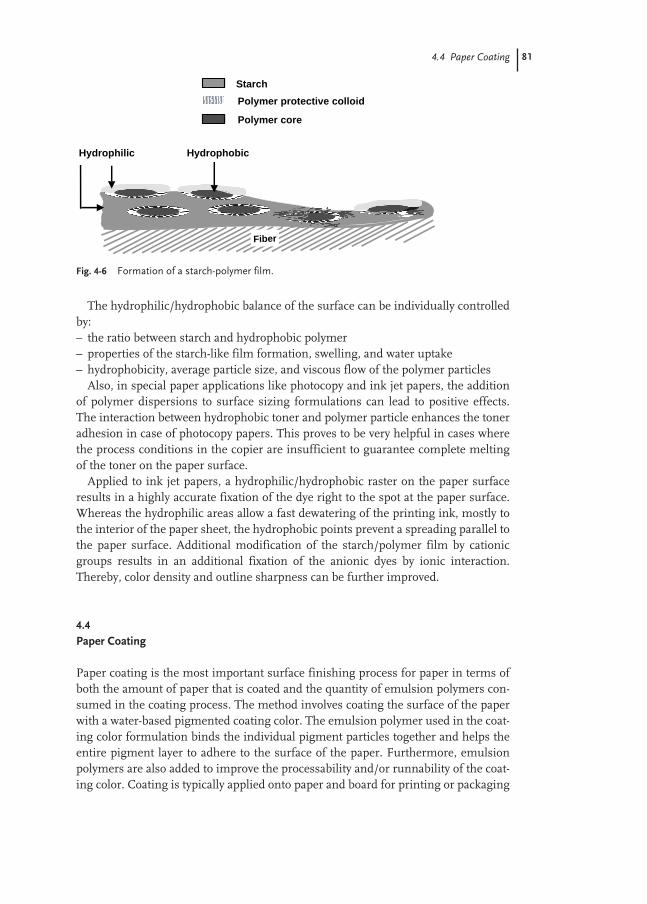
4.4 Paper Coating 81
The hydrophilic/hydrophobic balance of the surface can be individually controlledby:– the ratio between starch and hydrophobic polymer– properties of the starch-like film formation, swelling, and water uptake– hydrophobicity, average particle size, and viscous flow of the polymer particles
Also, in special paper applications like photocopy and ink jet papers, the additionof polymer dispersions to surface sizing formulations can lead to positive effects.The interaction between hydrophobic toner and polymer particle enhances the toneradhesion in case of photocopy papers. This proves to be very helpful in cases wherethe process conditions in the copier are insufficient to guarantee complete meltingof the toner on the paper surface.
Applied to ink jet papers, a hydrophilic/hydrophobic raster on the paper surfaceresults in a highly accurate fixation of the dye right to the spot at the paper surface.Whereas the hydrophilic areas allow a fast dewatering of the printing ink, mostly tothe interior of the paper sheet, the hydrophobic points prevent a spreading parallel tothe paper surface. Additional modification of the starch/polymer film by cationicgroups results in an additional fixation of the anionic dyes by ionic interaction.Thereby, color density and outline sharpness can be further improved.
4.4
Paper Coating
Paper coating is the most important surface finishing process for paper in terms ofboth the amount of paper that is coated and the quantity of emulsion polymers con-sumed in the coating process. The method involves coating the surface of the paperwith a water-based pigmented coating color. The emulsion polymer used in the coat-ing color formulation binds the individual pigment particles together and helps theentire pigment layer to adhere to the surface of the paper. Furthermore, emulsionpolymers are also added to improve the processability and/or runnability of the coat-ing color. Coating is typically applied onto paper and board for printing or packaging
Fig. 4-6 Formation of a starch-polymer film.
Polymer protective colloid
Polymer core
Starch
Hydrophilic Hydrophobic
Fiber

82 4 Applications in the Paper Industry
applications. Other specialty kinds of paper that undergo coating are labels, wallpa-per, and non-printed silicone papers which act as the backing sheets for self-adhesivelabels.
Coating paper or board increases the homogeneity of the surface and considerablyimproves its optical characteristics such as gloss, smoothness, brightness, and opac-ity. The properties of the pulp severely limit the surface homogeneity achievable withuncoated papers. The surface of an uncoated paper will contain fibers which are ap-proximately 1–3 mm (1000–3000 µm) long and approximately 10 µm thick. If this pa-per is printed by the halftone process using a 50 lines/cm screen, the dots (200 µm)are smaller than the dimensions of the fiber. The fibers are thus the limiting factordictating image definition. In contrast, the pigments used in the coating color can beeasily ground to a particle size of less than 1 µm. While the surface of an uncoatedpaper comprises numerous individual fibers of varying degrees of hardness, thesurface of a coated paper is, by contrast, uniform and homogeneous in structure.Figures 4-7 and 4-8 demonstrate clearly the differences in the quality of offset androtogravure printing on coated and uncoated paper surfaces, respectively.
For the reasons given above, coated paper exhibits more uniform ink receptivityand better holdout than uncoated papers. Coating also produces a much smootherpaper surface that is particularly a significant factor when printing individual dots,especially when using a rotogravure process (Fig. 4-9).
Low basis-weight papers require a high degree of opacity if show-through (i.e.,when the printing on one side of the paper can be seen from the other side) is to beprevented. The opacity of an uncoated paper is determined by the cellulose fibersand any fillers it contains. While fillers are naturally better than cellulose in increas-ing opacity, they are unable to provide the opacity levels attainable by coating. Thecrucial factor determining opacity is the volume of the coating, since this determines
Fig. 4-7 Effect of coated paper on offset printing.
Uncoated grade,supercalendered
Coated grade,supercalendered
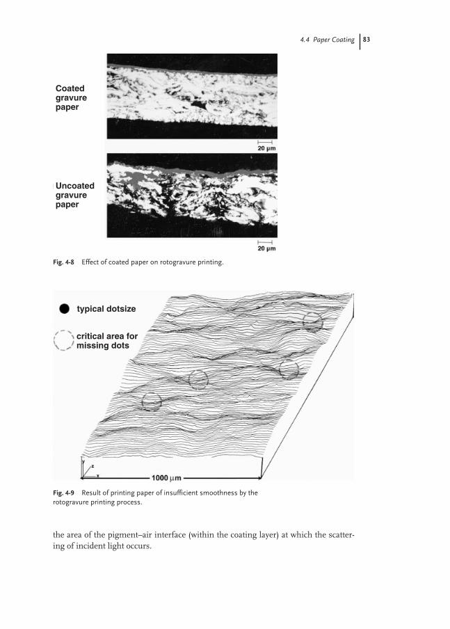
4.4 Paper Coating 83
the area of the pigment–air interface (within the coating layer) at which the scatter-ing of incident light occurs.
Fig. 4-9 Result of printing paper of insufficient smoothness by therotogravure printing process.
typical dotsize
critical area formissing dots
Fig. 4-8 Effect of coated paper on rotogravure printing.
Coatedgravurepaper
Uncoatedgravurepaper

84 4 Applications in the Paper Industry
Gloss is a critical property when assessing the quality of printing. Calendering isonly able to improve the gloss of an uncoated paper surface to a limited extent. Thegloss of a coated paper surface can be varied over a wide range, either by purely me-chanical means (calendering), by the coating process itself, or by controlled additionof gloss-imparting pigments. In this way, a full range of coated papers from high-gloss to semi-gloss to matte are easily obtained.
The degree of brightness can be controlled by selecting appropriate pigments, butcan also be adjusted by the use of optical brighteners or toning dyes or both. Thebrightness of a coated paper also depends strongly on that of the base paper. If thebase paper is of low brightness (e.g., unbleached), opacifying pigments such as tita-nium dioxide (TiO2) and special techniques such as double or triple coating are used.
4.4.1
Coating Techniques
A number of different coating machines exist for applying the coating color onto thebase paper. Figures 4-10a–c illustrate the common coating methods, along with therange of coating weights that can be achieved, the required level of solid content, andthe viscosity of the coating colors.
Stiff blades are more commonly used in North America, while bent blades aremore widely used in Europe.
It is apparent that the various coating methods place different demands on therheological properties of the coating color. These requirements must be taken intoaccount when formulating a coating color for a particular application.
The major components of a coating color are:– inorganic pigments to cover the surface of the base paper– co-binder and thickener for controlling the processing properties– binder (water-soluble or disperse systems or a combination of the two)

4.4 Paper Coating 85
Quantitatively, pigments are the principal constituent of any coating color, bindersbeing used in relatively small amounts. For every 100 parts pigment, there are typi-cally about 5–20 parts binder and 0.1–3 parts of other additives. Coating color com-positions common in both North America and Europe for sheet-fed offset and ro-togravure printing processes are listed in Tab. 4-2.
The quantities given here always refer to the amount of active ingredient required.A more detailed description of the constituents of a coating color is presented in
Sects 4.4.2–4.4.4.Once coated, the paper is smoothed as part of the calendering process. Calender-
ing involves subjecting the paper surfaces to high temperatures and pressures in or-
Fig. 4-10 Coating equipment. (A) Stiff blade, bent blade, and roll blade;(B) Air-knife; (C) Pre-metered size press.

86 4 Applications in the Paper Industry
der to create a smooth, glossy surface. A distinction is made between soft-nip calen-dered and supercalendered papers. In the soft-nip calender process, the number ofnips is kept low, and higher temperatures and lower pressures are used, compared tothe supercalender process. The advantages of the soft-nip calendering are that it canbe performed “on-line”, i.e., immediately after the coating process and that the bulkof the paper does not decrease as much as in supercalendering. By varying tempera-ture and pressure in a controlled manner, a very broad range of gloss levels can beachieved. In the supercalender, the number of nips used to smooth the paper isgreater, with typically twelve rolls in a supercalender stack. The smoothest andglossiest paper surfaces are achieved by supercalendering.
4.4.2
Pigments used in Coating Colors
The main constituents of a coating color formulation are the inorganic pigments,which serve to cover the surface of the base paper and thus to improve its opticalproperties.
Coating pigments must therefore satisfy the following requirements:– high purity– high brightness and opacity– high refractive index– good dispersibility and desirable rheological properties– amount of binder required should be low
The most important pigments are:– kaolin clay (often referred to simply as china clay)– calcium carbonate, natural or precipitated– titanium dioxide
Tab. 4-2 Typical coating color compositions for sheet-fed offset and rotogravure printing process-es in both North America and Europe.
Sheet-fed offset Rotogravure
North American formulation75 parts fine kaolin clay25 parts fine ground calcium carbonate12 parts emulsion polymer3 parts starch0.5 parts calcium stearate
European formulation80 parts fine ground calcium carbonate20 parts fine kaolin clay (high gloss clay)12 parts emulsion polymer0.5 parts co-binder0.5 parts curing agent0.5 parts optical brightener
North American formulation85 parts delaminated clay15 parts talc5 parts emulsion polymer2 parts starch0.5 parts calcium stearate
European formulation50 parts talc50 parts kaolin clay (coarse or high aspect ratio)5 parts rotogravure sole binder0.75 parts calcium stearate

4.4 Paper Coating 87
Nearly in all cases, not one but a combination of several pigments is used in coat-ing color formulations. Kaolin clay and calcium carbonate are the most commonlyused pigments. There are a great number of different types in each of the two pig-ment groups: the calcium carbonate grades being distinguished mainly by particlesize, while the plate-like kaolin clays are classified according to their so-called aspectratio (ratio of surface diameter to thickness) and particle size.
In the recent years, the use of ground calcium carbonate pigments in North Amer-ica has been steadily increased so that the differences in coating color formulationsbetween North America and Europe are being narrowed.
The pigments used in the preparation of coating colors are prepared as slurries.These are aqueous dispersions which by using dispersing agents such as tetrasodi-um pyrophosphate or sodium polyacrylate can have a solid pigment content ofgreater than 70 %.
The different pigments require different amounts of binder in order to ensure ad-equate adhesion of the coating to the surface of the paper and sufficient binding be-tween the pigment particles. For this reason, it is important to keep the specifiedbinder-to-pigment ratios when formulating coating colors. The following table(Tab. 4-3) lists the amount of binder required by various pigments to achieve a givenlevel of binding strength (pick strength) for sheet-fed offset printing paper.
More binder is needed when coating board to ensure good glueability in foldedcardboard boxes.
4.4.3
Co-binders and Thickeners used in Coating Colors
Pumping, transfer, re-circulation, and, most particularly, the actual coating methodrequire certain rheological properties of the coating colors. Low-shear and high-shear viscosities (shear rates of 10 to >106 s–1) and water retention values are highlyimportant parameters. For example, in roll coating applications, the thixotropic be-havior of the coating color is particularly important, whereas Newtonian or struc-turally viscous (i.e. pseudoplastic or shear-thinning) flow at high shear rates is im-portant for all blade coating techniques. Coating colors are characterized by their vis-cosity, solid content, immobilization point, and water retention capacity.
Tab. 4-3 Amount of binder in coating colors as a function of pigment type.
Pigment Binder demand (%)
Paper Board
Kaolin clay 12 14Ground calcium carbonate 11 12Precipitated calcium carbonate 15 18Titanium dioxide 14 16

88 4 Applications in the Paper Industry
To adjust these properties to the required level, co-binders and thickeners areadded to coating color formulations. If possible, these additives should be chosen tohave a positive influence on the gloss, smoothness, printability, brightness, bindingstrength, and glueability of the paper, and they should certainly not have a detrimen-tal effect on any of these properties. Typical amounts are 0.1–3 parts of co-binder orthickener to 100 parts pigment and approximately 12 parts binder. In addition to theemulsion polymers described in greater detail below, other substances are used asco-binders and thickeners. These include natural products such as starch and syn-thetic water-soluble polymers such as polyvinyl alcohol and carboxymethylcellulose.The chemical composition and the behaviors of co-binders and thickeners with re-spect to pH are shown in Fig. 4-11.
In contrast to the emulsion polymers used as binders, those employed as co-binders and thickeners contain large fractions of hydrophilic (typically carboxyl-rich)monomers. This high degree of hydrophilicity means that the particulate nature ofthe dispersion is lost when the acidic dispersion (pH < 7) is added to the alkaline en-vironment of the coating color formulation (pH > 7). The resulting structures, whichrange from massively swollen polymer networks to polymer chains dissolved in theaqueous phase, influence the rheology of the coating color in a complex manner andare still not fully understood.
Apart from the increase in the viscosity of the aqueous phase due to the dissolvedpolymer molecules, which are present as stiff chains at the pH of the coating color
Fig. 4-11 Chemical structure of synthetic co-binders.
Alkali
Alkali
Dispersion
pH < 7
Hydrophobicpolymer chains
in form of small balls
(dispersion particles)
- COOH
- COOH
- COO
- COO
Anionic chargesrepel each other,polymer chains
stretch and dissolve
Solution
pH > 7
MAIN MONOMERSCH2=CH-COOH Acrylic acidCH2=C(CH3)-COOH Methacrylic acidCH2=CH-COO-R Acrylic acid estersCH2=CH-CN AcrylonitrileCH2=CH-O-CO-CH3 Vinyl acetate

4.4 Paper Coating 89
formulation, polymer bridges also form between the pigment particles (Fig. 4-12).These structures, which are strongly dependent on the state of shear in the coatingcolor, result in a rise in its low-shear viscosity. If, in addition, one succeeds in incor-porating hydrophobic side chains into the polymer, the resulting associative interac-tion between the dissolved chains enables the low-shear viscosity to be increased stillfurther.
Fig. 4-12 Thickening mechanisms with various types of alkali-soluble co-binders andthickeners. (A) Alkali solubilization and thick-
ening behaviors of various acrylate copolymers;(B) Various thickening mechanisms of syn-thetic co-binders and thickeners.
Associative thickening
Extended polymer chainsLatex particles
Bridges between pigments
Solution+ Alkali (pH>7)
Dispersion
Carboxylategroups with
anionic charges
Polymer bridgesbetween
pigment particles
High viscosity atlow shear
Additionalhydrophobicside chains
Associativeinteractions
between polymers
Additionalnetwork structures
(micelles)
Very highviscosity at low shear
Functionalgroups withhigh polarity
Adsorption on pigment
surfaces
Anioniccharges repel
each other
Extendedpolymer chains
in the aqueous phase
Viscosityin the
aqueous phase
A
B
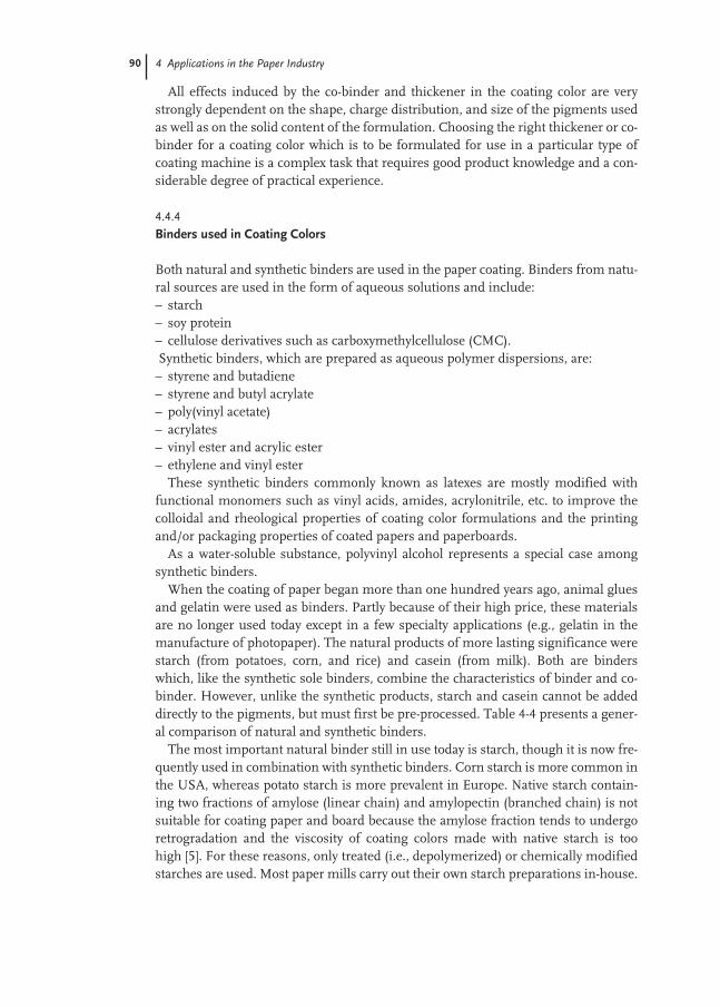
90 4 Applications in the Paper Industry
All effects induced by the co-binder and thickener in the coating color are verystrongly dependent on the shape, charge distribution, and size of the pigments usedas well as on the solid content of the formulation. Choosing the right thickener or co-binder for a coating color which is to be formulated for use in a particular type ofcoating machine is a complex task that requires good product knowledge and a con-siderable degree of practical experience.
4.4.4
Binders used in Coating Colors
Both natural and synthetic binders are used in the paper coating. Binders from natu-ral sources are used in the form of aqueous solutions and include:– starch– soy protein– cellulose derivatives such as carboxymethylcellulose (CMC).Synthetic binders, which are prepared as aqueous polymer dispersions, are:– styrene and butadiene– styrene and butyl acrylate– poly(vinyl acetate)– acrylates– vinyl ester and acrylic ester– ethylene and vinyl ester
These synthetic binders commonly known as latexes are mostly modified withfunctional monomers such as vinyl acids, amides, acrylonitrile, etc. to improve thecolloidal and rheological properties of coating color formulations and the printingand/or packaging properties of coated papers and paperboards.
As a water-soluble substance, polyvinyl alcohol represents a special case amongsynthetic binders.
When the coating of paper began more than one hundred years ago, animal gluesand gelatin were used as binders. Partly because of their high price, these materialsare no longer used today except in a few specialty applications (e.g., gelatin in themanufacture of photopaper). The natural products of more lasting significance werestarch (from potatoes, corn, and rice) and casein (from milk). Both are binderswhich, like the synthetic sole binders, combine the characteristics of binder and co-binder. However, unlike the synthetic products, starch and casein cannot be addeddirectly to the pigments, but must first be pre-processed. Table 4-4 presents a gener-al comparison of natural and synthetic binders.
The most important natural binder still in use today is starch, though it is now fre-quently used in combination with synthetic binders. Corn starch is more common inthe USA, whereas potato starch is more prevalent in Europe. Native starch contain-ing two fractions of amylose (linear chain) and amylopectin (branched chain) is notsuitable for coating paper and board because the amylose fraction tends to undergoretrogradation and the viscosity of coating colors made with native starch is toohigh [5]. For these reasons, only treated (i.e., depolymerized) or chemically modifiedstarches are used. Most paper mills carry out their own starch preparations in-house.

91
The properties of the starch depend on how it is treated or modified. The best resultsare achieved by ethylation. However, the most economical method of modification isenzymatic degradation to prepare enzyme-converted starches. Also, oxidized starch-es are widely used in North America. Table 4-5 compares the advantages and disad-vantages of using starch as a binder.
In addition to starch, another natural binder still used in North America is soy pro-tein. It is mainly used for recycled board coatings.
Emulsion polymers were first used successfully as coating color binders in thenineteen forties. The advantages and disadvantages of these synthetic binders aresummarized in Tab. 4-6.
The binder in a coating color formulation must be capable not only of binding thepigment particles together, but also of securing them at the coating surface and ofanchoring them to the base paper. The pigment particles at the coating surface mustbe held sufficiently tightly so that the coated paper can be smoothed in calenderingand subsequently printed. The mechanical stress experienced by the surface of thepaper depends very much on the printing process used and on the tack of the chosen
Tab. 4-4 Comparison of natural binders including polyvinyl alcohol with synthetic binders.
Natural binders and Synthetic binderspolyvinyl alcohol
Sold as Solid (powder) DispersionQuality consistency Good to poor Very goodDissolution/digestion needed Yes NoConcentration in aqueous form Maximum 10–20 % 50 %Viscosity in aqueous form High Low Film properties Very hard and brittle Variable, ranging from soft
to hard, thermoplastic, elasticTendency to foam Casein yes; starch no YesBacterial decay Yes NoWater retention High Practically noneBinding strength (pick strength) Medium high High-very highWater resistance Poor Very good
Tab. 4-5 Evaluation of starch as a binder.
Advantages Disadvantages
Low-price binder Low binding strength compared to synthetic bindersImproves runnability, particularly Highly soluble in water, low wet-pick strengthwell-suited for roll coating (thixotropic Not compatible with satin white coating colors can be prepared) Risk of non-uniform printing in an offset printingCoating colors with a high solid content Variable quality of commercial productscan be prepared Liable to rot
4.4 Paper Coating
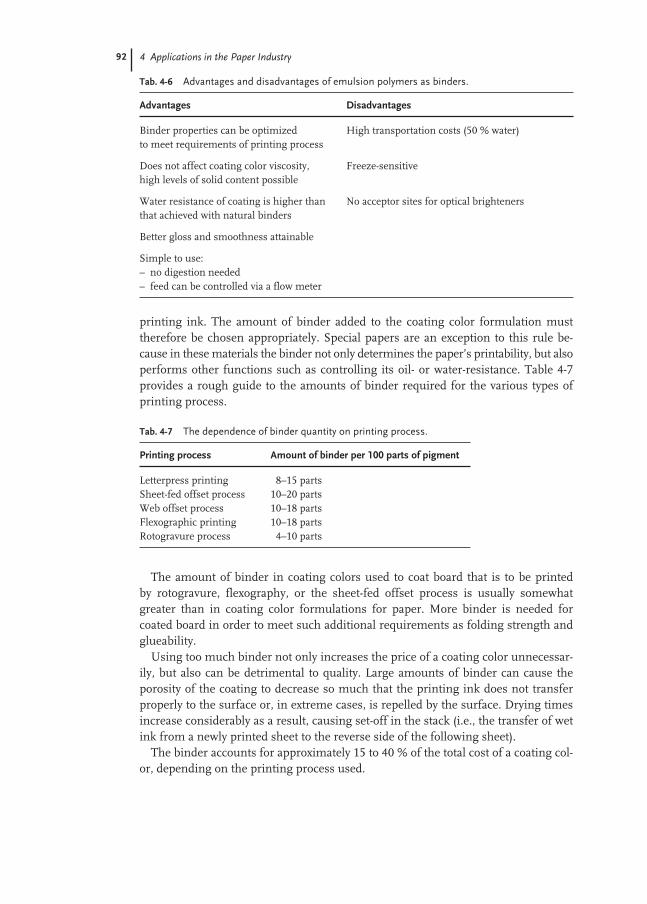
92 4 Applications in the Paper Industry
printing ink. The amount of binder added to the coating color formulation musttherefore be chosen appropriately. Special papers are an exception to this rule be-cause in these materials the binder not only determines the paper’s printability, but alsoperforms other functions such as controlling its oil- or water-resistance. Table 4-7provides a rough guide to the amounts of binder required for the various types ofprinting process.
The amount of binder in coating colors used to coat board that is to be printed by rotogravure, flexography, or the sheet-fed offset process is usually somewhatgreater than in coating color formulations for paper. More binder is needed for coated board in order to meet such additional requirements as folding strength andglueability.
Using too much binder not only increases the price of a coating color unnecessar-ily, but also can be detrimental to quality. Large amounts of binder can cause theporosity of the coating to decrease so much that the printing ink does not transferproperly to the surface or, in extreme cases, is repelled by the surface. Drying timesincrease considerably as a result, causing set-off in the stack (i.e., the transfer of wetink from a newly printed sheet to the reverse side of the following sheet).
The binder accounts for approximately 15 to 40 % of the total cost of a coating col-or, depending on the printing process used.
Tab. 4-7 The dependence of binder quantity on printing process.
Printing process Amount of binder per 100 parts of pigment
Letterpress printing 8–15 partsSheet-fed offset process 10–20 partsWeb offset process 10–18 partsFlexographic printing 10–18 partsRotogravure process 4–10 parts
Tab. 4-6 Advantages and disadvantages of emulsion polymers as binders.
Advantages Disadvantages
Binder properties can be optimized High transportation costs (50 % water)to meet requirements of printing process
Does not affect coating color viscosity, Freeze-sensitivehigh levels of solid content possible
Water resistance of coating is higher than No acceptor sites for optical brighteners that achieved with natural binders
Better gloss and smoothness attainable
Simple to use:– no digestion needed– feed can be controlled via a flow meter
4.4 Paper Coating 93
In addition to the amount of binder used, which is a dominant factor determiningthe binding strength, the type of binder is also of crucial significance in determiningthe properties that influence the appearance and classification of paper and board.These important properties are:– pick resistance (dry pick strength, IGT method, Pruefbau)– water resistance or wet pick resistance (wet pick strength, IGT method, Pruefbau)– gloss (specular reflection intensity)– brightness (reflection of visible light λ = 475 nm)– opacity (hiding opposite to transparency)– smoothness (Parker Surface Roughness Test, etc.)– porosity– compressibility (rotogravure)– stiffness (more important for light-weight papers)– drying/setting of printing inks– mottling (uneven uptake of ink)– water absorption capacity (the capacity of the paper to absorb water, thus permit-
ting the transfer of inks to moist surfaces)– ink absorption capacity (the capacity of the paper to absorb ink and to prevent ink
being transferred from the freshly printed areas to the rubber blanket of the fol-lowing printing station)
– blistering in web offset process (blister-free printing)– glueability of board and packaging paper
In Sect. 4.4.5, the most important methods of testing coated papers will be de-scribed.
The extent to which a coated paper needs to fulfil the various requirements listedabove depends on the printing process to be used. The most exacting requirementson binder strength must be met by paper grades to be printed by the sheet-fed offsetprocess. Because an aqueous fountain solution is used in the offset process, the wetpick strength (i.e. the binding strength of the moist paper) is crucially important. Asthe sheet-fed offset process is principally used to create high-quality prints, the de-mands made on optical parameters (brightness, gloss) and on printability (ink ab-sorption, absence of mottling) are particularly stringent.
As the printing inks used in a web offset press have less tack than those used inthe sheet-fed offset process, the requirements on the binding strength for paperprinted by the web offset process are not so high. However, the paper must exhibithigh resistance to blistering. Once printed, the paper in a web offset press passesthrough a drier in order that the printing ink solvents and any residual water withinthe base paper can evaporate. If the porosity of the coating is too low, the water vaporcan become trapped causing blistering and detachment of the coating layer.
The rotogravure process uses inks with a very low viscosity. It therefore has thelowest requirements in terms of the pick strength of the paper. To guarantee theeven and error-free transfer of the printing inks (i.e. low number of missing dots)from the rotogravure cells to the paper, requires paper which is both smooth andcompressible.

94 4 Applications in the Paper Industry
When choosing or developing a suitable binder for one of the various printingprocesses, one generally focuses on those four parameters whose effect on binderproperties is sufficiently well known. These are:– nature of the constituent monomers– glass transition temperature– particle size and particle size distribution– molecular structure of polymers
As mentioned at the beginning of this section, the binders used in coating colorformulations are based on combinations of different monomers. The most commoncombinations are styrene with butadiene or acrylic esters and vinyl acetate combinedwith ethylene or acrylic esters. An important difference between styrene-butadienebinders and styrene-acrylic ester binders is the tendency of the binder to yellow underthe influence of UV radiation or heat. Products containing a butadiene-based binderare considerably more susceptible to yellowing due to the much greater fraction ofdouble bonds in the polymer. Acrylic ester copolymers are significantly less prone tothermal or UV-induced yellowing (as shown clearly in Figs 4-13 and 4-14) and theseare the copolymers of choice for the production of high-quality, long-life prints.
Generally speaking, binders based on polyvinyl acetate or on styrene-acrylate pro-duce a more porous coating than do binders based on a butadiene copolymer.
The glass transition temperature of a polymer is determined by the amounts of itsdifferent monomer constituents. Paper used in offset printing contains binderswhose glass transition temperature lies between 0 °C and 30 °C. The high smooth-ness and compressibility required for paper grades used in the rotogravure printingprocess are achieved by using binders with a much lower glass transition tempera-ture (<0 °C). Figure 4-15 shows the typical dependence of dry and wet pick strength,stiffness, gloss, porosity, and evenness of offset printing on the glass transition tem-perature.
Fig. 4-13 Thermal yellowing as a function of the chemical composition ofthe binder.

4.4 Paper Coating 95
Particle size and particle size distribution are influenced by the choice andamounts of emulsifiers and protective colloids that a polymer dispersion contains.These components are added to stabilize the dispersion thus making it both process-able (i.e., enabling it to be conveyed, metered, filtered, etc.) and storable. Variationsin the emulsion polymerization process also have a major effect on the size and sizedistribution of the polymer particles. Typically, binders used in the paper coatingprocess have particle sizes of between 100 and 300nm. Figures 4-16 and 4-17 demon-strate that both the viscosity of the coating color and the wet pick strength of thecoated paper are strongly dependent on particle size.
In contrast to the other possible monomer components, butadiene possesses twodouble bonds both of which can act as polymerization sites. Binders based on astyrene-butadiene combination therefore have a more cross-linked and branchedpolymer structure. The extent of cross-linking affects the dry and wet pick strength,the print gloss and the degree of blistering, which is a highly significant parameter in
Fig. 4-14 UV-induced yellowing as a function of the chemical compositionof the binder.
0
2
4
6
8
10
12
14
Base paper
After 8 hours of UV exposure
Chemical BasisStyrene/Butadiene/Acrylate
Chemical BasisStyrene/Acrylate
Chemical BasisStyrene/Butadiene
Brightness Loss
Fig. 4-15 Dependenceof paper properties onthe glass transitiontemperature of thebinder. Glass transition temperature (Tg)
Goal Goal
- wet pick- paper gloss- porosity
- dry pick- print gloss- printability
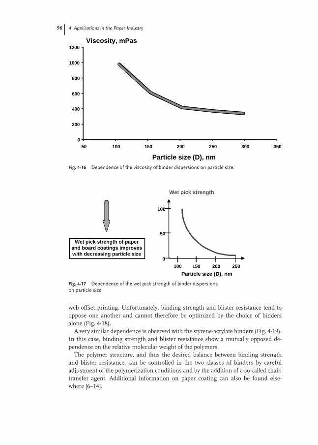
96 4 Applications in the Paper Industry
web offset printing. Unfortunately, binding strength and blister resistance tend tooppose one another and cannot therefore be optimized by the choice of bindersalone (Fig. 4-18).
A very similar dependence is observed with the styrene-acrylate binders (Fig. 4-19).In this case, binding strength and blister resistance show a mutually opposed de-pendence on the relative molecular weight of the polymers.
The polymer structure, and thus the desired balance between binding strengthand blister resistance, can be controlled in the two classes of binders by carefuladjustment of the polymerization conditions and by the addition of a so-called chaintransfer agent. Additional information on paper coating can also be found else-where [6–14].
Fig. 4-17 Dependence of the wet pick strength of binder dispersions on particle size.
Wet pick strength of paperand board coatings improveswith decreasing particle size
Wet pick strength
100 150 200 250
100
50
0
Particle size (D), nm
Fig. 4-16 Dependence of the viscosity of binder dispersions on particle size.
0
200
400
600
800
1000
1200
50 100 150 200 250 300 350
Viscosity, mPas
Particle size (D), nm

4.4 Paper Coating 97
4.4.5
Test Methods
In this section, the most important methods of testing coated papers will be de-scribed. The printability and the final print quality can often be successfully predict-ed on the basis of these relatively simple tests.
Coating strength testsThe strength required for a paper surface is to a large part determined by the tack ofthe ink used in the printing process. Whether or not the paper is dampened prior toprinting is also of considerable importance, particularly in the offset process. The fol-lowing tests simulate the stresses experienced by the paper surface during the print-ing process, in particular ink splitting during the offset process (Fig. 4-20).
Fig. 4-18 Relationship between blister resistance and binding strength for styrene-butadiene binders.
Blister resistance Pick strength
% Gel contentLow High
Pick strengthBlister
resistance
Fig. 4-19 Relationshipbetween blisterresistance and bindingstrength for styrene-acrylate binders.
Blister resistance Dry pick strength
Molecular weight of Styrene/Acrylate copolymers

98 4 Applications in the Paper Industry
Wet pick testThis is a test to determine the water resistance of a coated paper. After wetting thetest strip at constant speed and uniform pressure to create a precisely defined mois-ture content, the strip is printed with the testing ink while moving at constant orincreasing speed through the press.
Using a hole template to define ten separate measuring dots (representingprecisely defined strip speeds), the color density of each of the ten dots is measuredusing a densitometer and then expressed relative to the full tone of the printed sur-face. When plotted as a function of printing speed, the color density values are ameasure of the water resistance of the paper strip.
When the paper strip is printed at constant speed, the measuring dots used todetermine color density are chosen randomly.
Dry pick testThis test determines the tensile strength of the coating strip when subjected to inksplitting during the printing process:
The test strip is printed at a precisely defined plate pressure while being accelerat-ed through the printing zone. The location of the first picking point and the positionat which picking is visible right across the test strip are determined by inspection andanalyzed quantitatively with the aid of a computer program.
However, since in practice, the paper passes through not one but several printingpresses (4–8 in the offset process), a further test can be performed to examine theeffects of this sequential stressing of the paper surface. This is the so-called offsettest.
Fig. 4-20. Ink splittingin offset printing.
printing ink
blanket
paper or board
ink splitting
Cylinder

4.4 Paper Coating 99
Offset testThis test simulates repeated ink splitting caused by contact between the printed areaand the rubber blanket during the printing process.
Ink is transferred to the test strip from a plate at an exactly specified plate pressureand a constant known printing speed. The printed region is subsequently reprintedfive times at 10-s intervals using the same plate but without re-inking. The numberof passes at which the first signs of picking become apparent is recorded. In NorthAmerica, Paper-Ink Stability Test (P&I Test) is widely used [15]. The test measuresthe rate of ink setting by calculating the slope of the ink splitting force as a functionof the number of impressions taken at a given time interval. Also, this test measuresthe number of passes-to-fail. In general, the faster the rate of ink setting, the lowerthe number of passes-to-fail. Therefore, for press runnability, the rate of ink settingand the number of passes-to-fail must be balanced.
Printability tests
Mottle testThis test determines the evenness of the printing.
Ink is transferred to the test strip from an inked plate at an exactly specified platepressure and a defined constant speed, and subsequently split three times by an off-set rubber blanket-covered cylinder. If the coating on the paper is unevenly distrib-uted, the printed image may appear cloudy as a result. The inhomogeneity of theprinted image is either ranked visually or with a mottle tester (which measures fluc-tuations in color density).
Measurement of ink glossA test strip is printed using a precisely defined plate pressure and constant printingspeed. Once the test strip is dried, the ink gloss is measured using a gloss meter.
Ink set-off testThis test measures the speed at which the oils in the printing ink penetrate the coat-ing of the paper during the drying (setting) process: A test strip is printed from aninked plate applied at a precisely defined pressure and a constant printing speed. Ablank counter strip is pressed against the original strip once every 15 s during the du-ration of the test (900 s). The counter strip will pick up some of the non-dried print-ing ink from the original strip. The color density of any ink transferred to the count-er strip is measured using a densitometer. The Paper-Ink Stability Test mentionedas an offset test can provide information on ink set-off in terms of the ink settingrate [15].
Rotogravure testThis test determines the suitability of paper or board for printing by the rotogravureprinting process: To perform this test, a gravure cylinder and blade must be added toa standard IGT tester. The gravure cylinder is inked and the excess ink removedfrom the non-printing areas by the blade. Printing is carried out at a constant speed

100 4 Applications in the Paper Industry
and a defined force exerted by the impression cylinder. Each test strip is examined todetermine the length at which 20 missing dots have occurred. This particular testmethod is known as Helio test.
4.5
Concluding Remarks
Science and technology in the fields of paper surface sizing and paper coating havebeen significantly advanced over the past two decades and will be continued to moveforward to meet the needs in the paper industry. There are many challengesconfronting the paper industry. Some of the challenges are conservation of rawmaterials, especially trees as fiber source, by improving the current basis weight vs. stiffness relationship as well as by using recycled and secondary fibers moreeffectively, environmentally friendly papermaking, coating, and finishing processes,better quality coated paper and paperboard products at lower costs, etc. Thesechallenges will require us to continuously innovate in papermaking, coating, andfinishing. It will be interesting to see how well the paper industry can succeed in the21st century.
AcknowledgmentsOne of the co-authors (DIL) would like to thank his two other co-authors (JS-T andES) for letting him contribute to this chapter. This chapter has been based on an English translation of the Paper Industry portion of Chapter 5 Anwendung in derPapier- and Graphischen Industrie, by Jürgen Schmidt-Thümmes, Elmar Schwar-zenbach, and Berhard Prantl in Polymerdispersionen, Dieter Distler (ed.), Wiley-VCH,1998.

101
References
1 P. A. Ita, World Emulsion Polymers, The Freedonia Group, September, 1999.
2 BASF Corporation.3 G. D. McGinnis, F. Shafizadeh, Cellu-
lose and Hemicellulose, Chapter 1 in:Pulp and Paper: Chemistry and ChemicalTechnology, 3rd edn, Vol. I, J. P. Casey(ed.), John Wiley and Sons, 1980, pp. 1–38.
4 Paper, The New Encyclopaedia Britannica,Vol. 9, Encyclopaedia Britannica, 1987,p. 126.
5 R. L. Kearney, H. W. Maurer (ed.), Starchand Starch Products in Paper Coating,Tappi Press, 1990.
6 L. Göttsching, Papier in unserer Welt,Econ Verlag, Düsseldorf, Vienna, New York, 1990.
7 T. W. R Dean, The Essential Guide to Aqueous Coating of Paper and Board, Pita,Lancashire, UK, 1997.
8 G. L. Booth, Coating Equipment andProcesses, Lockwood, New York, 1970.
9 R.W. Hagemeyer, Tappi Monograph Series, 1976, 38.
10 A. R. Sinclair, Tappi Monograph Series,1975, 37.
11 E. J. Heiser, F. Kaulakis, Tappi Mono-graph Series, 1975, 37, 22–63.
12 T. F. Walsh, L. A. Gaspar, Tappi Mono-graph Series, 1975, 37, 98–119.
13 J. J. Latimer, H. S. De Groot, TappiMonograph Series, 1975, 37, 120–136.
14 R. C. Jezerec, G. P. Cogan, TappiMonograph Series, 1975, 37, 64–69.
15 N. P. Sandreuter, Tappi Coating Confer-ence Proc., 211, 1994.

103
5
Applications for Printing Inks
Barna Szabo
5.1
Introduction
The major printing processes used worldwide are: lithographic, gravure, flexograph-ic, screen, letterpress and digital. Flexography is the only printing process that con-sumes significant quantities of water based (aqueous) ink. Less than 23 000 tons peryear of water based ink are used for gravure printing in the US and less than14 000 tons in Japan; water based gravure volumes are negligible in Europe and LatinAmerica. Solvent based ink is used mostly for printing gravure, although it is readilyadaptable to aqueous ink. Oil- and solvent-based ink systems are used in the litho-graphic and letterpress processes. Lithography is the largest volume printingprocess. Letterpress is one of the smallest. Both water and solvent based inks are usedin screen and digital printing; these consume comparatively small volumes of ink.
In the United States, approximately two-thirds of flexographic ink is water based;one-third is solvent based in an estimated flexographic ink market of 200 000 tons.The major volume of water based flexo ink consumed in the United States is forprinting corrugated containers. The total US ink market for all six printing process-es listed above is estimated at over 1.1 million tons for year 2000 or approximately 4.5 billion $US.
In Europe, approximately two-fifths of flexographic ink is water based; three-fifths is solvent based in an estimated flexographic ink market of 180 000 tons. The total European ink market for all six printing processes is estimated at over 0.9 mil-lion tons for year 2000 or approximately 4.4 billion $US.
In Latin America less than one-third of flexographic ink is water; greater than two-thirds solvent based in an estimated flexographic ink market of 34 000 tons. The totalLatin American ink market for all printing processes is over 125 000 tons for year2000 or approximately 750 million $US.
The flexo ink market in Japan is very small. Approximately one-half of flexograph-ic ink consumed is water based; one-half solvent in an estimated flexographic inkmarket of 27 000 tons. The total Japanese ink market for all six printing processes isover 400 000 tons for year 2000 or approximately 1.5 billion $US.

104 5 Applications for Printing Inks
The aqueous ink market in 2000 is summarized in Tab. 5-1.
Emulsion polymers are used in flexographic and gravure ink for printing flexiblepackages, paperboard cartons, corrugated boxes, multi-wall bags, newspapers, andother flexible substrates (films) and paper products. Styrene acrylic based emulsionpolymers are most commonly used in printing ink applications. Cost is a key factorin ink raw material suitability for most ink systems. The level of styrene monomerused in ink grade emulsion polymers is maximized due to film hardness require-ments of paper and paperboard materials and its low price.
Prior to the mid 1970s, rosin fumarates (i.e. sodium and amine rosin salts) werethe main resins used in aqueous ink. Aqueous rosin based resin solutions providethe performance properties similar to use of rosin phenolic and rosin maleic pen-taerythritol esters in a lithographic printing ink. Rosin based resins have been usedin printing ink since the early days of letterpress printing. They are low cost, give in-herently good pigment dispersion properties, and are easily modified to vary viscosi-ty and hardness. When aqueous flexo and gravure printing began displacing solventbased systems, a wider range in properties than possible with rosin became impor-tant.
Emulsion polymers provide a wide range in properties and low viscosity. Flexo andgravure inks are referred to as fluid inks because of their low viscosity. Molecularweight, Tg (glass transition temperature), and particle size distribution are key prop-erties that are varied to meet specific ink requirements.
Pigment dispersion stability, room temperature film formation, and ink re-solu-bility are important properties to consider in the design of emulsion polymers forprinting ink. A “support” resin (Sect. 5.2.2) is used in most ink grade emulsions tomaintain these properties. The “support” resin is a low to medium molecular weightstyrene acrylic or other water soluble resin. It comprises up to 60 % solids content ofthe emulsion and replaces up to 90 % of surfactant stabilizers.
5.1.1
Flexographic Ink
A flexo ink is a low viscosity (fluid ink) suitable for transfer from an ink fountain viaanilox roll to the plate cylinder and substrate. It dries by evaporation of the solvent(water). Most presses are equipped with air circulating dryers. A flexo ink is com-prised of low boiling point solvents for low temperature evaporation and fast drying.
Tab. 5-1 The aqueous ink market in 2000.
Flexo ink Solvent-based Total flexo ink Total printing inkWater-based × 103 tons, estimated × 103 tons, estimated
Water and solvent
US 2/3 1/3 200 1100Europe 2/5 3/5 180 910Latin America <1/3 >2/3 34 125Japan 1/2 1/2 27 400
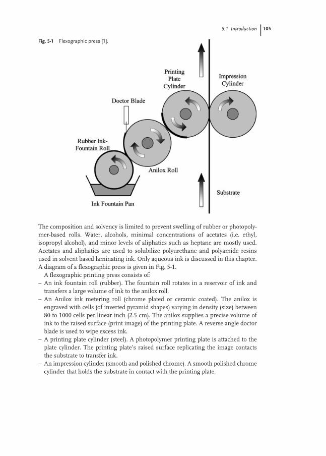
5.1 Introduction 105
The composition and solvency is limited to prevent swelling of rubber or photopoly-mer-based rolls. Water, alcohols, minimal concentrations of acetates (i.e. ethyl,isopropyl alcohol), and minor levels of aliphatics such as heptane are mostly used.Acetates and aliphatics are used to solubilize polyurethane and polyamide resinsused in solvent based laminating ink. Only aqueous ink is discussed in this chapter.A diagram of a flexographic press is given in Fig. 5-1.
A flexographic printing press consists of:– An ink fountain roll (rubber). The fountain roll rotates in a reservoir of ink and
transfers a large volume of ink to the anilox roll.– An Anilox ink metering roll (chrome plated or ceramic coated). The anilox is
engraved with cells (of inverted pyramid shapes) varying in density (size) between80 to 1000 cells per linear inch (2.5 cm). The anilox supplies a precise volume ofink to the raised surface (print image) of the printing plate. A reverse angle doctorblade is used to wipe excess ink.
– A printing plate cylinder (steel). A photopolymer printing plate is attached to theplate cylinder. The printing plate’s raised surface replicating the image contactsthe substrate to transfer ink.
– An impression cylinder (smooth and polished chrome). A smooth polished chromecylinder that holds the substrate in contact with the printing plate.
Fig. 5-1 Flexographic press [1].

106 5 Applications for Printing Inks
5.1.2
Gravure Ink
A gravure ink is a low viscosity (fluid ink) with rheological characteristics suitable fortransfer “out of” small cells of an engraved cylinder to the substrate. A gravure ink iscomprised of low boiling point solvents for low temperature evaporation and fastdrying. Gravure utilizes various environmentally compliant solvents as required byspecific printing applications. Only water based ink is discussed in this chapter. Adiagram of a gravure press is given in Fig. 5-2.
A gravure printing press consists of:– A gravure print cylinder (chrome). The gravure cylinder is engraved with cells of
varying sizes replicating the print image. The cylinder rotates through the inkfountain. Ink fills the cells. An excess is wiped by a doctor blade. Ink is transferreddirectly from cylinder to substrate.
– An impression cylinder. The impression cylinder is a rubber coated cylinder thatkeeps the substrate in contact with the print cylinder. Its function is to control inktransfer. The ink is drawn out of the cells of the print cylinder by means of im-pression pressure and capillary action. An ESA (electrostatic assist) mechanism issometimes used to assist in the capillary action. Ink rheology, electron charge andsurface energy are key variables that effect transfer.
5.2
Ink Composition
An aqueous flexo or gravure printing ink is composed of polymer, pigment, solvent,wax, surfactant, crosslinker, and additives. The polymer (resin) functions as the“vehicle” for carrying the pigment. It is also a key component for achieving printing
Fig. 5-2 Gravure press [2].

5.2 Ink Composition 107
performance properties. The polymer is the material or compound for dispersing apigment and preventing its re-agglomeration. It provides adhesion to the substrate.The branched network of the polymer provides hold-out on porous substrates. Thesmooth surface provides gloss for desirable visual effects. Oxidized or crosslinkedpolymer structures provide resistance to “chemicals” that contact printed packages.It provides resistance to scuffing or rubbing. It provides resistance to environmentalconditions such as: heat and temperature, freeze–thaw, ozone, light, oxidation, mois-ture, etc. The polymer provides viscosity and rheology characteristics necessary fortransfer of ink from press to substrate.
The pigment provides the color. Organic pigments are used in most cases forlightfastness and transparency. Colorfastness and lightfastness is important to main-tain desirable visual effects of printed materials. An average consumer would notpurchase a food item (i.e. box of cereal) with faded or shifted colors. This effectwould convey a message about its lack of freshness. Water (solvent) is used to solu-bilize the resin or polymer. Water is used mainly in flexo and gravure printingprocesses. Other solvents such as ethyl-isopropyl alcohol, ethyl-isopropyl acetate,toluene, and heptane are also used in flexo and gravure ink, but only aqueous flexoand gravure inks are discussed in this chapter.
Illustrated in Tab. 5-2 is a generic formulation for an aqueous flexographic orgravure ink. A printing ink formula is frequently modified to meet exact color repro-duction specifications and/or a customer’s changing performance requirement.
Most commercially manufactured printing inks are made from intermediatessuch as: pigment dispersion (Sect. 5.2.1), emulsion vehicle (Sect. 5.2.2), solution ve-hicle(Sect. 5.2.3), and wax emulsion compound (Sect. 5.2.4). Using intermediatesminimizes the number of raw materials handled at the ink manufacturing or blend-
Tab. 5-2 Generic aqueous flexo or gravure ink formulation.
Aqueous flexographic ink Amount Gravure ink Amount Component (%, w/w) Component (%, w/w)
Pigment dispersion (Sect. 5.2.1) 35–50Dispersion varnish 55–70Organic pigment 30–45Total 100
Emulsion vehicle (Sect. 5.2.2) 25–35Solution vehicle (Sect. 5.2.3) 10–20Amine neutralizer 0.5–1.5Wax emulsion compound 2–5Wax powder 0–2Surfactant 1–1.5Crosslinking additive 0–2Silica additive 2–5Corrosion inhibitor 0–1Defoamer 0–1Other additives 0.25–0.5Total 100

108 5 Applications for Printing Inks
ing site. It facilitates the production of ink in blending plants with minimal equip-ment and at locations close to the customer and/or printer. Producing ink from in-termediates offers flexibility in modifying formulas to meet color reproduction spec-ifications and changing customer application requirements.
5.2.1
Pigment Dispersion
The pigment dispersion is made from dry pigment (which is surface treated) dis-persed in an aqueous polymer solution. High speed mixers are used to disperse apigment from a dried form or an aqueous slurry. The most common polymers usedto disperse pigments are: low to mid-molecular weight styrene acrylics, SMA(styrene maleic anhydride), or rosin fumarate ester resins. The degree of stabiliza-tion of a pigment dispersion (which relates directly to color strength development),ink viscosity stability, transparency and pH drift are controlled by use of polymerssuch as those containing salt groups and hydroxyl functionality. Table 5-3 illustratesthe physical properties of polymers used for dispersing pigments.
The stabilization of organic pigment dispersions is achieved by use of polymericanionic surfactants that provide strong adsorption on the polar surface of the pig-ment and hydroxyl groups for interaction with the aqueous phase. Non-polar inter-mediate sections of a polymeric anion add adsorbed layer thickness [3].
A typical organic pigment particle size ranges between 0.02 to 100 µm (aggregatesize). The particle size distribution of particles in a pigment dispersion are typically0.5 to 1.5 µm. Most emulsion polymers used in printing ink vary between 20 nm to200 nm. Because of a pigments relatively large particle size and its wide range in par-ticle size distribution, the smaller emulsion polymer particles are not suitable forforming stable dispersions of organic pigment particles and agglomerates. They donot have sufficient mobility to wet the surface area.
Pigments used in aqueous flexo and gravure ink are supplied as a presscake, in dryform, or as chips. A presscake is a high solids dispersion of pigment in water. Apresscake is dried by various drying processes to yield pigment agglomerates in alarge range of particle sizes, between 0.02 to 100 µm. Chips are a dry form of dis-persed pigment particles in a polymer.
Most pigments used in pigment dispersions for printing ink are surface treatedwith a resin or polymer compatible with the pigment surface chemistry. The poly-
Tab. 5-3 Solution polymers used for pigment dispersions.
Softening Glass transition Mw (g mol–1) Acid numberpoint (°C) temp., Tg (°C) (mg KOH g–1)
Styrene acrylic I 140–170 70–125 12000– 18000 210–240Styrene acrylic II NA 15– 20 30000– 35000 65– 70SMA ester NA 45–110 50000–150000 165–285Rosin fumarate ester 125–145 80– 90 2000– 10000 115–200
5.2 Ink Composition 109
mer is added as a dissolved aqueous solution during the “pigment striking” step. Itadheres to the pigment surface via physical and/or chemical attraction. Surface treat-ed pigments are known as “resinated” pigments. A pigment is surface treated or“resinated” as part of the pigment manufacturing process. A resinated pigment min-imizes agglomeration, contributes to increased color value and improves the effi-ciency of the dispersion process. An explanation about the type of resins and poly-mers used for surface treatment of pigment is a separate segment of ink-pigmenttechnology that is not covered in this chapter.
It is important that resins or polymers used in the surface treatment of pigment,are compatible and do not react with the resins and polymers used in the pigmentdispersion. Furthermore, they must be compatible with the emulsion and solutionvehicles of the ink. Incompatibility between these components may cause: pigmentre-agglomeration (resulting in a loss of color strength), increased low shear viscosity(known as “thixotropy”) leading to a change in ink rheology, and poor printability(e.g. variable ink transfer) performance.
In addition there are various hybrid resins in use to disperse a pigment. They areused to achieve specific ink application properties not obtainable by the convention-al resins and polymers discussed above. For example, a glycerol ester of fumaratedrosin is further esterified with a styrene-allyl alcohol as taught in Westvaco ChemicalCorporation’s patent – Rosin-Based Grind Resins for Aqueous Printing Ink. Thistype of resin has high softening point and gives relatively stable low viscosity ink [4].A fumarated rosin polyamine condensation resin is explained in a second Westvacopatent – Modified Rosin Resins for Waterbased Inks. The condensation reactionproduct of polyamines with certain rosin-based polycarboxylic acids results in an ef-ficient pigment dispersion resin and gives a stable viscosity over a wide range in pH,between 8.5 to 10.5 [5]. These resins and others not discussed provide alternatives fordispersing pigments.
5.2.2
Emulsion Vehicle
The emulsion vehicle provides the “workhorse” performance characteristics of anink (i.e. adhesion, gloss, low viscosity, printability, re-solubility in water, heat, andchemical resistance at low cost). Most printing ink emulsion vehicles are polymerdispersions composed of styrene acrylics, terpolymers of styrene-α-methylstyreneand other acrylate monomers (i.e., ethyl acrylate, methyl methacrylate, butyl acrylate,2-ethylhexyl acrylate, methacrylic acid, acrylic acid, 2 hydroxyethyl acrylate, aminoacrylate). Higher levels of styrene give higher Tg. Higher levels of butyl and 2-ethyl-hexyl acrylate give lower Tg, thus more flexible polymers. Compared to other poly-mers (i.e. polyurethanes) styrene acrylics do not give good alkali resistance, chemicalresistance, or adhesion to films and lamination ink (cohesive) bond strength.
Emulsion vehicles are prepared by emulsion polymerization in water in the pres-ence of surfactant stabilizers. Viscosity is not dependent on molecular weight butonly on solids content and particle size distribution. As a result, high molecularweights (>200 000 g mol–1) are achievable at low viscosity. Emulsions with small par-
110 5 Applications for Printing Inks
ticle sizes impart properties similar to solution resins with advantages of: low viscos-ity, near Newtonian rheology, pH stability, low polarity, and insolubility after dryingfor immediate water resistance.
Most printing ink emulsions are “resin supported”. Printing ink emulsion poly-mers contain a “support” resin to reduce MFFT (minimum film forming tempera-ture), and insure film coalescence. A “support resin” also decreases the need for sur-factants. A support resin provides ink re-wettability, improves compatibility with pig-ment dispersions, and improves ink transfer and printability. Support resins are typ-ically styrene acrylic polymers with acid functionality that are amine neutralized.
A rosin fumarate ester can be used as a “support” resin for ink grade emulsions.According to Westvaco’s US Patent 5 216 064 [6], a fumarated rosin ester offers ad-vantages such: as improved gloss, absence of residual glycol used in processing astyrene acrylic, and higher resin solids. A higher solids emulsion gives faster drying.Rosin based support resins are lower cost. Westvaco’s US Patent 5 656 679 teachesthat a rosin fumarate reacted with an alkanolamine containing at least one secondaryamine and one hydroxyl group is used as a support resin for ink grade emulsions forproviding improved adhesion to films [7].
Polyurethanes are known to give excellent chemical and product resistance prop-erties but increase cost. A water soluble polyurethane is made by adding acid modi-fied monomer to the polymer backbone, the polymer is neutralized with amine, thenused as a support resin in ink grade styrene acrylic emulsions. Polyurethane sup-ported styrene acrylic emulsion polymers may be used to balance the high cost ofpolyurethanes and provide improved chemical resistance [8].
Emulsion polymers are supplied in bulk quantities at solids levels between 45 and 60 %. They are produced by emulsion polymer manufacturers such as: SC Johnson Polymer, Rohm & Haas, Avecia, Air Products, Westvaco, B.F. Goodrich and others.
Outlined in Tab. 5-4 are: applications, emulsion characteristics, and physical prop-erties of the styrene acrylic emulsion vehicles used in flexo and gravure ink. Anemulsion vehicle comprises 25 to 35 % of the total ink formula. The table is sorted byincreasing Tg.
For printing inks that require specific properties not obtainable by conventionalstyrene acrylic emulsions, an aqueous dispersion of an acid functional polyurethane-epoxy acrylate hybrid (self crosslinking for improved chemical resistance) [9] patent-ed by Air Products and Chemicals, Inc. or a self crosslinking styrene acrylic emul-sion which reacts upon evaporation of water [10] patented by Akzo Nobel Resins BV,may be used. The Air Products novel dispersion contains a quaternary ammoniumpolyurethane acrylic hybrid carboxylate salt and pendant acrylate epoxide that self-crosslink upon evaporation of water and ammonia. Akzo’s novel polymer contains adiacetone acrylamide reactive monomer and a bishydrazide. The crosslinking reac-tion between ketone groups and a bishydrazide proceeds rapidly at room tempera-ture, after evaporation of water from the ink.

5.2 Ink Composition 111
Tab.
5-4
Typi
cal s
tyre
ne a
cryl
ic e
mul
sion
veh
icle
s us
ed in
flex
o an
d gr
avur
e pr
intin
g in
ks s
orte
d by
incr
easi
ng T
g.
App
licat
ion
P.S.
S.
C.
pHV
isco
sity
M
wA
.N.
T gM
FFT
(nm
)(%
)(m
Pas)
(gm
ol–1
)(m
g K
OH
g–1)
(°C
)(°
C)
Surf
ace
prin
t65
–75
47–4
98.
2–8.
470
0–90
0>2
0000
035
–50
–30
to1
<7
Pre
-pri
nt c
orru
gate
d12
0–14
020
–25
7.9–
8.3
2500
–600
070
000–
1000
0012
0–13
010
–35
<24
Dir
ect p
rin
t cor
ruga
ted
160–
180
25–4
06.
0–7.
945
–250
0~1
0000
012
5–50
30–
35<2
4
Cu
p, p
late
, mu
lti-w
all b
ag, g
ift w
rap
40–
5045
–50
8.5–
9.5
150–
500
>200
000
40–
5540
–48
>45
Fol
din
g ca
rton
55–
6545
–50
7.9–
8.5
150–
500
>200
000
40–
5595
–105
>60
Fle
xo n
ews
180–
220
48–5
28.
2–8.
715
0–50
0>2
0000
040
–55
95–1
05>6
0
P.S
., n
um
ber
aver
age
part
icle
siz
e di
stri
buti
on in
nan
omet
er; S
.C.,
solid
s co
nte
nt;
A.N
., ac
id n
um
ber;
MF
FT
, min
imu
m f
ilm f
orm
ing
tem
pera
ture

112 5 Applications for Printing Inks
5.2.3
Solution Vehicle
Solution vehicles consist of water soluble polymers not manufactured by emulsionpolymerization. The solution vehicle is an alkali soluble polymer in aqueous solutionor a blend of polymers with combined properties into a single waterborne varnish.Soluble polymers are made by free radical polymerization in a processing solvent oras addition or condensation products with heat reaching temperatures up to 265 °C.Solution vehicles are mixtures of soluble resins unlike emulsion polymers. A solu-tion vehicle is used to increase adhesion to film and improve ink printability or trans-fer to meet specific performance requirements. The solution vehicle provides pig-ment dispersion stabilization, transparency, low film forming temperature, glossand re-solubility. An alkali soluble resin is a carboxylic acid functional polymer neu-tralized (solubilized) with ammonia, amine or sodium hydroxide. The acid numbersare generally above 100. Ammonia or volatile amines are used in most aqueous inksexcept for news print inks. After evaporation of the amine, the resin becomes insolu-ble and resistant to water spray or other water contact. The ink is re-solubilized withalkaline water for the clean-up cycle. For news print ink, the polymers are solubilizedwith sodium hydroxide to maintain re-solubility (open time) of the ink on the press.News print ink pressman prefer unlimited open time and fewer clean-up cycles. Wa-ter resistance is not required since ink penetrates the news print paper fibers.
The key solution polymers (resins) used in printing ink are styrene or rosin based.Styrene-α-methylstyrene monomer and acid functional co-monomers (i.e. acrylic ormethacrylic acid) comprise the bulk of styrene acrylic solution vehicles used in print-ing ink. Rosin acid reacted with fumaric acid gives a tri-functional “adduct”. The“adduct” is partially esterified with polyols such as pentaerythritol, glycerin, diethyl-ene glycol, etc. to achieve a range of acidity, viscosity, Tg and molecular weight.
The viscosity of aqueous polymer solutions is strongly dependant on molecularweight. High performance characteristics such as rub resistance and heat resistanceare compromised since low ink viscosity is required for flexo and gravure fluid inkprinting. The volatile amines used to neutralize acid functionality results in pHshifts, unstable viscosity, reduced pigment dispersion stability, and poor alkali re-sistance.
Water soluble styrene acrylics are processed via free radical polymerization in gly-col ether solvents. The solvent is stripped by conventional or proprietary processes.Rosin based resins are processed molten at high temperatures up to 265 °C. Thesematerials are flaked or pelletized and packaged in bags or bulk storage for furtherconversion.
There are various hybrid polymers and co-polymers in use to achieve specific inkapplication properties not obtainable by conventional resins and polymers. Watersoluble fatty acid epoxy esters provide improved heat resistance. For example, anaqueous fatty acid-acrylic acid epoxy ester patented by Reichold Chemical, whichcrosslinks via heat and auto-oxidation is used to provide water and heat resist-ance [11].
Typical solution polymers are listed in Tab. 5-5.

5.2 Ink Composition 113
5.2.4
Waterborne Wax Emulsions and Powders
Both natural and synthetic waxes are used in ink. Waxes provide increased block,rub, scuff and/or water resistance. Waterborne wax emulsions are produced in arange of particle sizes between 35 to 175 nm (number average particle size distribu-tion) by Michelman, Shamrock Wax, and others. Polyethylene and Fischer-Tropschemulsions improve the rub and scuff resistance of an ink. Carnauba paraffin andpolypropylene emulsions are used to prevent blocking and improve water resistanceof an ink.
Certain waxes are micro-pulverized to yield particle sizes smaller than a dispersedpigment particle. A micro-pulverized wax is “stirred” into ink as a powder. RecycledPTFE (Teflon) is supplied in small particle powder form.
5.2.5
Ink Additives
An amine neutralizer is added to solubilize resins containing carboxylic acid func-tionality. The amine reacts with the resin carboxylic acid to form a water soluble salt.Volatile amines such as dimethylaminoethanol (DMAE), morpholine or ammoniaare used to insure that a printed product becomes water resistant upon drying orevaporation of the amine. The type of amine used is selected based on press speed,pH requirement and evaporation rate and press drying capacity. Sodium hydroxideis commonly used in news print ink to maintain re-solubility (“open time”) of the inkon the press.
A crosslinking compound is added to provide covalent branching to a polymer forenhanced printed film tensile strength and chemical resistance characteristics. Com-
Tab. 5-5 Typical solution polymers.
Resin/Polymer Softening Tg Mw Acid point (°C) (°C) (g mol–1) number
Surface print Styrene acrylic resin 145 73 4500– 7500 108–213Folding carton Direct print corrugatedPre-print corrugatedAlternative folding carton Rosin fumarate Direct print corrugated ester resin 125–145 80–90 2000–10000 115–200Pre-print corrugatedMulti-wall bags and gift wrapMilk carton Fatty acid (Castor oil)/ >125 >100 30000–40000 50–60Cup and plate acrylic epoxy esterTowel and tissue Styrene acrylic 75–100 6000–10000 200–230
Water and amine neutralizer

114 5 Applications for Printing Inks
pounds such as zinc ammonium complexes or zinc oxide react with available car-boxylic acid functionality. Self crosslinking emulsion polymers may be used as ex-plained in Sect. 5.2.2.
A surfactant is added to reduce the surface tension to give increased ink spreadingand substrate wetting particularly when printing untreated or partially treated films.The surface tension of water is approximately 72 dynes cm–1 whereas a polyethylenefilm is approximately 30–40 dynes cm–1 after surface treatment. Surfactants increasethe foaming tendency of an ink. Therefore levels of surfactant and defoamer arecarefully balanced.
A defoamer is added to reduce foaming. A fine particle size silica powder is addedto increase the viscosity and modify print film slip or abrasion properties.
A corrosion inhibitor is added to prevent corrosion of press parts made of steel.
5.3
Physical Properties and Test Methods
Viscosity, pH and color strength are the main properties that relate to press per-formance and print quality. Viscosity is critical for satisfactory ink transfer or print-ability. A gravure ink has slightly lower viscosity than a flexo ink. The pH is con-trolled since it effects viscosity, viscosity stability and compatibility with other com-ponents. The viscosity changes with change in pH, but is readily adjusted by addingamine or water.
Color accuracy (ink color strength) is important for achieving satisfactory print col-or and to maximize profitability. The color strength of a pigment dispersion inter-mediate is carefully controlled to narrow tolerances. Therefore, color adjustments inthe ink manufacturing step are minimized.
5.3.1
Typical Properties
The typical properties or specifications of aqueous flexo and gravure ink are:Viscosity, Zahn efflux cup (ref. ASTM D4212-99) @ 25 °C:Flexo ink shipping viscosity, Zahn #3 25–30 sGravure ink shipping viscosity, Zahn #3 21–25 sFlexo ink printing viscosity, Zahn #3 18–22 sGravure ink printing viscosity, Zahn #2 18–22 sZahn #3 8–10 spH 9.0–9.5Color accuracy (ASTM D2244-93) <2.0 Delta E* (CIELAB total color
difference) versus standardFineness of grind, (ASTM D1316-93) <2.0Residue (ref. ASTM F311-97) <15 mg per 100 g ink

5.3 Physical Properties and Test Methods 115
5.3.2
Application Tests
Application specific pass/fail tests are specified to guarantee that an ink shipmentgives satisfactory performance. The application properties are measured relative to astandard sample. The results are reported as pass or fail versus the standard. The fol-lowing application tests are performed on aqueous flexo and gravure ink:– Abrasion resistance, dry/wet rub resistance, Sutherland Rub Tester– Adhesion at surface tension of 38–44 dynes cm–1, Scotch 610 Tape Test– Block resistance– COF (coefficient of friction), ink to ink, static at 26.6° slide angle– COF (coefficient of friction), ink to ink, kinetic at 19.3° slide angle– Crinkle resistance at room temperature or that of ice water– Drying with a 1 millimicron or 2 mil fineness of grind gauge– Freeze-thaw resistance, two cycles– Heat resistance, 98 °C– Milk carton wet rub– Product resistance – acid, fertilizer, limestone, wood oil– Re-wetting– Rub test – metal corrugator– Surface tension of film– Viscosity, Zahn efflux cup– Water resistance, 24 h, immersion at 25 °C
5.3.3
Test Method Abstracts
– Abrasion resistance – Sutherland Rub Tester: A test strip (18.8 cm) is rubbed by afour pound test block with a 15 cm × 7.5 cm strip affixed. The test is run either:ink-to-ink or unprinted paper-to-ink, 20 to 40 rub cycles according to specifications.A subjective comparison is made to a photograph standard or control sample that istested subsequently. This test method simulates scuffing that may occur duringin-line filling, handling or transporting of a package. Wax emulsions or micro-pul-verized powders are added to adjust the abrasion resistance properties of an ink.For heated abrasion resistance, the four pound test block is held in an oven for
twenty minutes at a temperature specified. The test simulates scuffing that may occuron hot filling lines or under high friction conditions.
For wet-rub resistance (approximately twelve drops) water is applied to a 18.8 cmtest strip with a pipette. Un-printed paper is used to test paper or board substrates. Aswatch of cotton material is used to test film substrates.
The test simulates rubbing of a package by cotton clothing.– Adhesion/Scotch 610 Tape Test: A 2.5 cm wide 3-M 610 tape is attached to the ink
and pulled off at an angle of 180 degrees. Ink removal of greater than 10 % is a fail-ure. This test is performed to flag unusual problems associated with poorly treatedfilms or ink composition errors

116 5 Applications for Printing Inks
– Block resistance – wet/dry – ink to ink and ink to substrate: The exposure time,pressure, and temperature are specified by the end use requirement (i.e. 3 min at1034 bar, 50 °C for surface print ink (5.4) – The ink surface’s resistance to heat andpressure is subjectively measured. Ink properties that effect blocking results are:“hardness”, adhesion, cohesion, and slip. The polymer glass transition tempera-ture (Tg), molecular weight, and surface compatibility effect the block resistancetest.
– Coefficient of friction measurement, TMI slip and friction tester: The peak angle(static) and average force (kinetic) are measured. An emulsion polymer with lowglass transition temperature is required for high slide angles.
– Crinkle resistance test at room temperature or at the temperature of ice water: Theprint is immersed in ice water for one hour (re-ice water crinkle). Two surfaces ofink are rubbed ink to ink for 10 cycles. Perform a subjective comparison between atest sample and a standard.
– Drying test with a 1.0 mil (25 µm) or 2.0 mil (50 µm) fineness of grind gauge: Dry-ing time is measured subjectively by finger tapping and a stopwatch. A polymer’sglass transition temperature, MFFT and emulsion particle size distribution effectdrying.
– Freeze–thaw test: A sample of ink is placed in a freezer at –15 °C for 4 h. Changesin viscosity, homogeneity, and seeding tendency are observed.
– Heat resistance test at 100 °C – Sentinel heat seal tester: Set-up a Sentinel heatsealer according to heat pressure and time interval specified. A one by three inch(2.5 cm × 7.5 cm) print sample is folded ink surface-to-ink surface and placed be-tween the sealer bars. The heat sealer is operated. After the sample has beencooled, the sheets are separated and a subjective comparison is made for cling, inktransfer and picking. The polymer glass transition temperature (Tg), molecularweight, and surface compatibility affect heat resistance.
– Milk carton wet rub test: A test print is immersed in milk at 1 to 7 °C for 24 h. Arub resistance test is performed using a Sutherland rub tester (see abrasion resist-ance). Specific polymers (Sect. 5.6.1) are used to give resistance to milk.
– Product resistance and/or chemical resistance – acid, fertilizer, limestone, woodoil, etc : Three drops of an appropriate chemical solution is applied using a 3-mL pipette. After a specified time interval, a cotton swab is rubbed through the drop over the print surface with moderate pressure. A comparison is made fordiscoloration, ink removal, or blistering. A polymer composition, branching struc-ture and crosslinking density have the largest effect on chemical resistance of anink.
– Re-wetting test: A #4 Meyer bar drawdown is allowed to dry for 20 min at RT(room temperature). A drop of water is placed on the ink surface and subsequent-ly wiped with a cloth. A subjective comparison is made versus a standard sample.Solution polymers are neutralized with volatile amines (Sect. 5.2.3) to prevent re-solubilization after the ink print dries.
– Rub test – metal corrugator: For pre-print liner board, this test simulates the ef-fects of a corrugator. The extent of scuffing/marring is subjectively compared to aphotographed standard. The emulsion polymer’s soft segment, glass transition

5.4 Inks for Flexible Substrates (Films) 117
temperature (Tg), and molecular weight have the largest effect on the rub resist-ance properties of an ink.
– Surface tension of film: Accudyne level pens or solutions are used to estimate thesurface tension of treated films. A targeted range of 38–42 dynes cm–1 is specifiedfor most printing applications. The surface tension of most aqueous styreneacrylic based pigmented inks are greater than 38–42 dynes cm–1.
– Viscosity, Zahn efflux cup (ref. ASTM D4212-99), seconds: A Zahn efflux cup is afast and effective instrument for measuring viscosity of flexo and gravure ink. Vis-cosity is an important property for maintaining printability. For a flexo press, con-sistency of ink flow into the pan or well of the doctor blade system, ink-transfer tothe anilox roller, and release of ink from anilox roller are largely effected by inkviscosity. On a gravure press the release of a consistent volume of ink out of thecylinder cell is effected by viscosity. Viscosity changes due to pH drift or evapora-tion of solvent (water) should be corrected immediately.
– Water resistance, 24 h, immersion at 25 °C: A Crinkle test is performed. Two sur-faces of ink are rubbed ink-to-ink for 10 cycles. A subjective comparison is madebetween a test sample and a standard.
5.4
Inks for Flexible Substrates (Films)
The ink used for printing flexible substrates (films) contains a soft film formingemulsion polymer based on styrene and co-monomers such as butyl acrylate, and 2-ethylhexyl acrylate. Solvent based inks have continued use in high performanceprinting applications such as packages requiring lamination bonds (i.e. candy wrap-pers, potato chip bags). Flexo and gravure printing companies have invested in sol-vent incinerators to remain compliant with environmental regulations. Examples ofmaterials used for flexible packaging films are:LDPE Low density polyethylene (i.e. fruit and vegetable produce bags)MDPE Medium density polyethylene (i.e. department store merchandize bags)HDPE High density polyethylene (i.e. grocery item bags)LLDPE Linear low density polyethylene
(i.e. department store merchandize bags)PP Polypropylene (i.e. salt, fertilizer bags)PP-EVA Ethylene vinyl acetate modified polypropyleneOPP Oriented polypropylenePP-NO Non-oriented polypropylenePP-AC Acrylic coated polypropylenePP-PVDC Poly(vinylidene chloride)-coated polypropylenePET Polyethylene terephthalatePVDC Poly(vinylidene chloride) (Saran)

118 5 Applications for Printing Inks
5.4.1
Surface Print Film
Surface print inks are designed for printing on polyethylene substrates used in utili-ty bags, department store merchandize bags, grocery bags, and general purpose sur-face film applications. The films are surface treated via corona discharge increasingto a surface tension of 38–41 dynes cm–1 before printing. A corona discharge inducesions and free radicals to oxidize the surface of a film to form polar functionality. Thischange in surface chemistry and roughness increases surface energy and improveswetting of ink on film. A surface print ink is composed of a soft film forming styreneacrylic emulsion vehicle to provide adhesion. A solution vehicle composed of lowmolecular weight styrene acrylic resin is added to adjust printability. Typical proper-ties of the emulsion polymers and solution resins used in ink for surface print filmsare listed in Tabs 5-3 and 5-4.
5.4.2
Lawn and Garden Bags
Lawn and garden bag inks are designed for printing on polyethylene or polypropy-lene substrates used in fertilizer, salt, mulch, potting soil, manure, feeds and woodbark bags. Lawn and garden bags require resistance to: weak acids, bases, fertilizers,limestone dust, wood oils (i.e. cedar, pine), etc.
A typical Lawn and garden bag ink has a similar composition to surface inks. Acrosslinking compound (i.e. zinc oxide, carbodiimide, polyfunctional aziridine) addscovalent branching, increases modulus and enhanced print film adhesion and re-sistance to chemicals.
As an alternative, a self crosslinking styrene acrylic emulsion which reacts uponevaporation of water may be used according to the Akzo Nobel Resins paper present-ed at the 44th NPIRI Technical Conference [10].
5.5
Inks for Paper Board Substrates
5.5.1
Folding Cartons
Folding carton inks are designed for printing on paper board (or boxboard) sub-strates used in: fast food carry out packages, pastry cartons, cereal boxes, mail con-tainers, auto parts boxes, beverage carriers, milk and juice cartons, and other pack-ages. Folding cartons are made from solid bleached kraft or solid bleached sulfate(SBS), unbleached kraft, solid unbleached sulfate (SUS), clay coated unbleachedkraft, recycled paperboard, and coated paperboard.
For beverage carriers, one substrate type is used consistently in most of the USmarket. Many beverage carriers are over-coated with a clear protective coating layer.
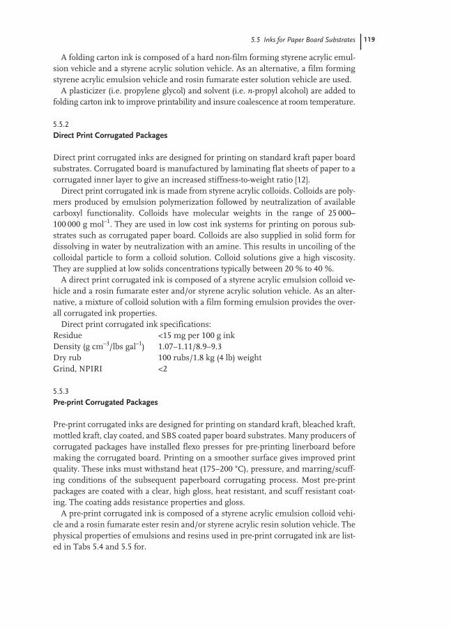
5.5 Inks for Paper Board Substrates 119
A folding carton ink is composed of a hard non-film forming styrene acrylic emul-sion vehicle and a styrene acrylic solution vehicle. As an alternative, a film formingstyrene acrylic emulsion vehicle and rosin fumarate ester solution vehicle are used.
A plasticizer (i.e. propylene glycol) and solvent (i.e. n-propyl alcohol) are added tofolding carton ink to improve printability and insure coalescence at room temperature.
5.5.2
Direct Print Corrugated Packages
Direct print corrugated inks are designed for printing on standard kraft paper boardsubstrates. Corrugated board is manufactured by laminating flat sheets of paper to acorrugated inner layer to give an increased stiffness-to-weight ratio [12].
Direct print corrugated ink is made from styrene acrylic colloids. Colloids are poly-mers produced by emulsion polymerization followed by neutralization of availablecarboxyl functionality. Colloids have molecular weights in the range of 25 000–100 000 g mol–1. They are used in low cost ink systems for printing on porous sub-strates such as corrugated paper board. Colloids are also supplied in solid form fordissolving in water by neutralization with an amine. This results in uncoiling of thecolloidal particle to form a colloid solution. Colloid solutions give a high viscosity.They are supplied at low solids concentrations typically between 20 % to 40 %.
A direct print corrugated ink is composed of a styrene acrylic emulsion colloid ve-hicle and a rosin fumarate ester and/or styrene acrylic solution vehicle. As an alter-native, a mixture of colloid solution with a film forming emulsion provides the over-all corrugated ink properties.
Direct print corrugated ink specifications:Residue <15 mg per 100 g inkDensity (g cm–3/lbs gal–1) 1.07–1.11/8.9–9.3Dry rub 100 rubs/1.8 kg (4 lb) weightGrind, NPIRI <2
5.5.3
Pre-print Corrugated Packages
Pre-print corrugated inks are designed for printing on standard kraft, bleached kraft,mottled kraft, clay coated, and SBS coated paper board substrates. Many producers ofcorrugated packages have installed flexo presses for pre-printing linerboard beforemaking the corrugated board. Printing on a smoother surface gives improved printquality. These inks must withstand heat (175–200 °C), pressure, and marring/scuff-ing conditions of the subsequent paperboard corrugating process. Most pre-printpackages are coated with a clear, high gloss, heat resistant, and scuff resistant coat-ing. The coating adds resistance properties and gloss.
A pre-print corrugated ink is composed of a styrene acrylic emulsion colloid vehi-cle and a rosin fumarate ester resin and/or styrene acrylic resin solution vehicle. Thephysical properties of emulsions and resins used in pre-print corrugated ink are list-ed in Tabs 5.4 and 5.5 for.

120 5 Applications for Printing Inks
Plasticizers (i.e. propylene glycol) and coalescing solvents (i.e. glycol ether) areadded to maintain satisfactory printability and satisfactory MFFT (minimum filmformation temperature).
5.6
Inks for Poly-coated Board
Inks for polymer coated paper board are designed for printing on polyethylene coat-ed SBS (solid bleached sulfate) paper board substrates used in milk cartons, icecream cartons, beverage cups, and paper plates.
A typical ink for coated board is composed of an epoxy ester based pigment dis-persion, styrene acrylic emulsion vehicle, and an epoxy ester solution vehicle. Theepoxy resin commonly used is an ester of drying or semi-drying fatty acid and acrylicacid (Sect 5.2.3). The system undergoes oxidation to give moisture and alkali resist-ance [11]. Alternative polymers that may be used in inks for coated board are: aziri-dine (ethylene imine) crosslinking styrene acrylic or a VAE (vinyl acetate ethylene)self crosslinking emulsion polymer.
5.6.1
Milk Cartons
Milk carton ink must have resistance to alkaline detergent based chain lubricants. Afatty acid acrylic epoxy ester [11] is the key resin used in this type of ink. Special pig-ment dispersions are used based on the same epoxy ester since conventional styreneacrylic based pigment dispersions are not stable in epoxy ester based systems.
5.6.2
Cup and Plate
Cup and plate inks must have tolerance for hot wax coatings and resistance to hotand cold fluids. They should meet the requirements for general purpose paper plateuse. A hard non-film forming styrene acrylic emulsion combined with hot-air drying(by oxidation) fatty acid-acrylic epoxy ester [11] provide the resistance requirements.
5.7
Inks for Paper Products
A typical ink used for printing multiple wall bags, gift wrap, and envelopes are com-posed of a hard non-film forming styrene acrylic emulsion combined with a solutionvehicle comprising a rosin fumarate ester to balance printability and coalescence. Apolymer with high molecular weight and Tg fast drying via fast: resin-solvent (water)separation, penetration of paper and brightness of color via “holdout” of pigmentparticles on the paper surface.

5.7 Inks for Paper Products 121
5.7.1
Multiple Wall Bags
Inks for Multiple Wall bags are designed for printing on kraft: brown, or bleached,mottled (compressed thin layers of bleached pulp on top of brown pulp), clay coated,and uncoated paper substrates. Flexographic printing is the most used process formulti-wall bags.
Multi-wall and other paper bags are made of one or more walls of paper glued to-gether and treated to provide moisture resistance. Heavy duty bags used as shippingsacks have three or more plies. Bags used for packaging consumer products (i.e. petfood, sugar, flower) have two plies. The paper used in bags for packaging consumerproducts has been upgraded in recent years to bleached kraft and clay coated.
5.7.2
Gift Wrap and Envelopes
Gift wrap is used for seasonal gifts, retail wrapping, liquor boxes, candy and otherproducts. The substrates used are 90 % paper and 10 % foil [12].
Inks for Gift Wrap are composed of a hard non-film-forming styrene acrylic emul-sion combined with a solution vehicle to adjust printability and balance coalescence.Gravure is the most used process for printing gift wrap.
Envelope ink is made from the same mix of polymers as gift wrap ink.
5.7.3
Newspapers
Newspapers were originally printed by the letterpress printing process. Low costblack ink was mostly used. A letterpress black ink is composed of carbon black dis-persed in high boiling point aliphatic petroleum solvent (ink oil). By 1995 the major-ity of newspapers converted to the offset lithographic printing process. Offset newsink is composed of carbon black or organic pigments dispersed in high boiling pointaliphatic petroleum solvent based vehicles. The vehicles are resin solutions in ink oiland/or vegetable oils (i.e. soybean oil). During the 1980’s the remaining letterpressprinters began to switch to the flexographic process and water based ink. Aqueousflexo news ink is based on higher cost emulsion polymers than typical petroleum hy-drocarbon resin based offset inks. Therefore it was necessary to target certain news-paper market segments with higher value products. Flexographic newspaper print-ing introduced brighter colors to comics and advertising, and overall increased colorcoverage per newspaper. A flexographic news ink contains a high molecular weight,styrene acrylic emulsion with high Tg (glass transition temperature) to provide fastdrying.
A typical flexographic news ink is composed of a hard semi-film-forming styreneacrylic emulsion vehicle.
122 5 Applications for Printing Inks
5.7.4
Towel and Tissue
The same styrene acrylic emulsions used for sizing tissue paper to provide wetstrength are used in the ink. The colorants used are mostly dyes or pigments that arenot dermatological irritants. The resin should give a waterproof bond and be lowcost. The components of a towel and tissue ink are re-pulpable for ease in recovery ofwaste and/or off-grade material to achieve satisfactory economies of paper towel tis-sue converting.
References
1 Western Michigan University Web Site:http://www.wmich.edu/ppse/flexo/,Flexographic Process
2 Western Michigan University Web Site:http://www.wmich.edu/ppse/gravure/,Gravure Process,
3 Wicks, Z. W. Jr., Jones, F. N., Pappas,S.P., Dispersions in Aqueous Media, in:Organic Coatings, Science and Technology,2nd edn, Wiley-Interscience, 1999,Chapter 20.3, p. 395.
4 Schilling, P. Westvaco Corporation, US Patent: 5,208,319, Rosin-BasedGrind Resins for Aqueous Printing Ink.
5 Zuraw, P. J., Westvaco Corporation , US Patent: 5,166,245, Modified RosinResins for Waterbased Inks, 1992.
6 Rivera, M. A.; Zuraw, P. J., WestvacoCorporation, US Patent: 5,216,064,Rosin-Based Resin-Fortified EmulsionPolymers
7 Hutter, G. F., Westvaco Corporation, US Patent: 5,656,679, Rosin Ester-AmideSupport Resins for Acrylic Latexes.
8 Biggerstaff, J. A., Reuther, P. C., Jack-son, K., Westvaco Chemical Division, A Comparison of Water-borne ChemicalResistant Technologies and the Variablesthat Affect their Performance, 43rdNPIRI Technical Conference, Septem-ber 15–17, 1999.
9 Tien, C., Mao, C., Snyder, J. M., Beck,A., Air Products and Chemicals, Inc.,US Patent 5,977,215, Low TemperatureSelf-Crosslinking, Aqueous Disper-sions of Urethane–Vinyl Polymers forCoating Applications.
10 de Krom, A., Mulder, H., Mestach, D.,Akzo Nobel Resins BV, Self-Crosslink-ing Acrylic Dispersions Outperform Con-ventional Solventborne Liquid Inks, 44thNPIRI Technical Conference, October18–20, 2000.
11 Meeske, C. J., Van der Tuin, E. H.,Racey, M. J., Reichold Chemicals, USPatent 4,166,054, Water DispersibleEpoxy resin Copolymers and Methodsof Making Same, 1979.
12 Eldred, R. N., Ph.D., Package Printing,Jelmar Publishing, 1993.

123
6
Applications for Decorative and Protective Coatings
Brough Richey and Mary Burch
6.1
Introduction
Decorative and protective coatings are used in a great variety of applications, rangingfrom the familiar such as coatings for buildings, furniture, automobiles, and largeindustrial structures, to less well known applications such as removable coatings, pa-per coatings, and specialized coatings for optical fibers and electronic components.Most coating applications have historically utilized solution polymers as the bindercomponent. However, concerns over pollution, the toxicity of solvents, and ease ofuse and clean-up have driven the development of new emulsion polymer technolo-gies to meet the needs of the coatings industry. The use of emulsion polymers forcoating applications has increased tremendously over the past fifty years and they arenow represented in nearly every segment of the industry. In fact, coatings based onemulsion polymers frequently set the performance standards and lead the market inmany areas.
The objective of this chapter is to give the reader an overview of the use of emul-sion polymers in decorative and protective coatings. Because of the great variety ofspecific applications, it will not be possible to address them all, and we have choseninstead to focus on selected application areas which we believe will provide the read-er with a useful foundation in a variety of coating applications.
6.1.1
Market Overview
The development, manufacture, sale and application of decorative and protectivecoatings comprise a large business and we estimate that approximately 20 billionliters of decorative and protective coatings are manufactured and applied each year,representing world wide sales of about $60 billion US [1]. Annual growth is typicallythe range of 1–3 % world wide, and is generally linked to the combined gross do-mestic product of the major industrialized and developing nations. Growth rates for

124 6 Applications for Decorative and Protective Coatings
water based coatings have been higher, in the 3–6 % range, with most of the extragrowth due to the switch from solvent based coatings.
We can obtain an estimate for the annual world wide production of emulsion poly-mers for decorative and protective coatings as follows. If we assume that water basedcoatings make up about 50 % of the total world wide volume, then approximately10 billion liters of water based paint are manufactured each year. To estimate theamount of emulsion polymer manufactured to yield this amount of coating material,we can estimate an “average” water based paint has about 30 % volume solids, withthe dry volume of binder representing about 50 % of this value. This yields an esti-mated 1.5 billion liters of solid emulsion polymer produced per year. Assuming anaverage polymer dry density of 1.1 kg L–1 and an average emulsion solids level of50 % by weight, it follows that the world wide production of emulsion polymer forcoating applications is about 3 billion wet kg (6–7 billion wet pounds) per year. Whilethis is admittedly a rough estimate, it nevertheless serves to illustrate the enormoussize of the water based coatings market and the large amount of polymer emulsionneeded to supply it.
6.1.2
Coating Industry Trends
The most significant trend in the decorative and protective coatings markets hasbeen the move to more environmentally friendly coating materials. The shift awayfrom traditional solvent borne technologies to newer technologies based on water-borne emulsion polymers, high solids coatings, and powder coatings is a key conse-quence of this trend. This change has been driven by a variety of regulatory pressuresaimed at reducing air pollution by lowering the volatile organic content (VOC) ofcoating materials. Related to these pollution concerns is the desire to increase thesafety of the end use application process, particularly in the area of decorative coat-ings for homes and offices. Again, this has caused a shift away from traditional sol-vent borne technologies toward newer technologies with improved health and safetyprofiles. Finally, world wide economic conditions have led to consolidation in thepaint manufacturing industry, and its associated raw material suppliers [2]. Theseeconomic factors have created a strong movement towards cost reduction and in-creases in production and distribution efficiency across the coatings industry. In ourview, the combination of continued technical innovation with improved cost effi-ciency presents the central challenge to the coatings industry as we move into thetwenty-first century.
6.1.3
Coatings Provide Decoration and Protection
It is common to divide the general class of coatings into two subclasses: decorativeand protective coatings. While this division can be useful, it can be also be mislead-ing; the vast majority of coatings systems provide both decoration and protection.Automotive coatings systems provide a familiar illustration of this dual role: they are

6.2 Overview of Coating Formulations 125
foremost a protective coating, and must protect the automobile body from damageby weathering and the environment; and yet, the color and appearance of automotivefinishes are vital factors which influence the customer’s purchase decision. Interiordecorative finishes provide an example at the other end of the decorative-protectivecontinuum. While used primarily for decorative purposes, the stain resistance andcleanability of interior finishes are important performance characteristics which of-ten provide differentiation in this competitive market.
6.2
Overview of Coating Formulations
Decorative and protective coatings consist of three main components:(i) pigment, which provides color and opacity to the coating(ii) binder, which holds the film together and provides coating integrity; and(iii) carrier liquid, which provides as the liquid character of the coating while in the
wet state (before drying).In this chapter, we will focus on coatings utilizing emulsion polymer binders, andconsequently, water will be the carrier liquid. These types of coatings are also com-monly referred to as latex paints, presumably in reference to the similarities in ap-pearance between the emulsion polymer binders and unprocessed natural rubber.
Commercial paint formulations are usually complex and typically contain morethan the three main components described above. These formulations usually haveon the order of 10–20 raw material components, the specific nature of which de-pends on the intended application. A more realistic formulation would include: dis-persed solids such as pigments and fillers stabilized by a polymeric dispersing agent,a dispersed emulsion polymer acting as the binder, a thickener to provide properrheology, coalescents and co-solvents to promote film formation and optimize thedrying process, surfactants to improve colloidal stability and promote substrate wet-ting, a biocide to prevent microbial spoilage, a defoamer to reduce foaming duringmanufacturing and application, and a neutralizing agent to adjust the pH. Many op-timized formulations contain more than one member of each of these classes. Theprimary technical challenge of coatings formulation is to develop cost effective coat-ing formulations which are stable indefinitely in the wet state, apply correctly to thesubstrate, dry into defect free films, and meet the appearance and performance re-quirements of the intended application.
6.2.1
Volume Solids and Pigment Volume Content
The relative ratios between the volumes of different formulation components controlmany of the key appearance and performance properties of a coating [3, 4]. Volumesolids is the simplest of these relationships; it is the ratio between the volume of sol-id components in a coating and the total volume of the wet coating. It typically is re-ported as a percentage. Volume solids is a useful quantity because it allows one to
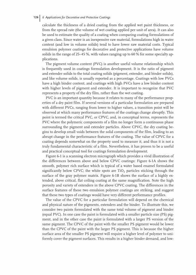
126 6 Applications for Decorative and Protective Coatings
calculate the thickness of a dried coating from the applied wet paint thickness, orfrom the spread rate (the volume of wet coating applied per unit of area). It can alsobe used to estimate the quality of a coating when comparing coating formulations ofa given class. Since water is an inexpensive raw material, formulations high in watercontent (and low in volume solids) tend to have lower raw material costs. Typicalemulsion polymer coatings for decorative and protective applications have volumesolids in the range of 25–45 %, with values ranging up to 60 % for some specialty ap-plications.
The pigment volume content (PVC) is another useful volume relationship whichis frequently used in coatings formulation development. It is the ratio of pigmentand extender solids to the total coating solids (pigment, extender, and binder solids),and like volume solids, is usually reported as a percentage. Coatings with low PVCshave a high binder content, and coatings with high PVCs have a low binder contentwith higher levels of pigment and extender. It is important to recognize that PVCrepresents a property of the dry film, rather than the wet coating.
PVC is an important quantity because it relates to many of the performance prop-erties of a dry paint film. If several versions of a particular formulation are preparedwith different PVCs, ranging from lower to higher values, a transition point will beobserved at which many performance features of the coatings change abruptly. Thispoint is termed the critical PVC, or CPVC, and, in conceptual terms, represents thePVC where the polymeric components of a film no longer form a continuous phasesurrounding the pigment and extender particles. Above CPVC, the dry coating be-gins to develop small voids between the solid components of the film, leading to anabrupt change in the performance features of the coating. The value of CPVC for acoating depends somewhat on the property used to measure it, and thus it is not atruly fundamental characteristic of a film. Nevertheless, it has proven to be a usefuland practical conceptual tool for coatings formulation development.
Figure 6-1 is a scanning electron micrograph which provides a vivid illustration ofthe differences between above and below CPVC coatings: Figure 6-1A shows thesmooth, polymer rich surface which is typical of a water based enamel formulatedsignificantly below CPVC; the white spots are TiO2 particles sticking through thesurface of the gray polymer matrix. Figure 6-1B shows the surface of a highly ex-tended, above critical, flat ceiling coating at the same magnification. Note the highporosity and variety of extenders in the above CPVC coating. The differences in thesurface features of these two emulsion polymer coatings are striking, and suggestthat these two types of coatings would have very different performance profiles.
The value of the CPVC for a particular formulation will depend on the chemicaland physical nature of the pigments, extenders and the binder. To illustrate this, weconsider two paints formulated with the same total volume of pigment and binder(equal PVC). In one case the paint is formulated with a smaller particle size (PS) pig-ment, and in the other case the paint is formulated with a larger PS version of thesame pigment. The CPVC of the paint with the smaller PS pigment would be lowerthan the CPVC of the paint with the larger PS pigment. This is because the highersurface area of the smaller PS pigment will require a higher level of polymer to uni-formly cover the pigment surfaces. This results in a higher binder demand, and low-
6.2 Overview of Coating Formulations 127
ers the PVC at which CPVC is reached. Comparing the actual PVC of a coating to theCPVC can provide useful information regarding a coating’s physical properties andsuitability for a particular application. Coatings formulated at PVCs below CPVCtend to have higher gloss, lower porosity, better flexibility and better barrier proper-ties. Coatings formulated above CPVC generally have lower gloss, higher porosity,lower flexibility and lower total cost. Since PVC level is usually adjusted upward byincreasing the levels of low cost extenders, PVC can provide a useful gauge of for-mulation cost (and quality). This measure is most useful for coatings formulatedabove CPVC. PVC is a less useful measure of quality in coatings formulated belowCPVC, since these coatings contain little or no low cost extenders and consist prima-rily of higher cost resins and pigments.
6.2.2
Polymer Matrix
The polymer or binder component holds the coating together and provides many ofthe performance features needed for specific coating applications. A high molecularweight polymeric material is generally used as the binder in order to provide thetoughness and resistance properties needed to protect the substrate and ensure adurable coating. In practical systems the minimum molecular weight of thermoplas-tic polymers targeted for coating applications is around 50 000 g mol–1 [5–7]. Poly-mers with molecular weight below this value generally do not have the requiredtoughness properties needed for coating applications: lower molecular weight crys-talline materials are generally too brittle and can chip or flake, while non-crystallinematerials such as amorphous waxes do not have high enough moduli to provide thefilm integrity needed for most coating applications.
Decorative and protective coatings are generally designed to perform their func-tion over the temperature range of –20 °C to +45 °C. The polymers used for coating
Fig. 6-1 Field Emission Scanning ElectronMicrographs of Below and Above CPVC Coat-ings. (A) shows the surface image obtainedfrom a gloss enamel coating which has beenformulated significantly below CPVC. (B) shows
the surface image obtained from a flat ceilingcoating which has been formulated significantlyabove CPVC. Note the porosity and variety ofextenders present in the coating formulatedabove CPVC.
128 6 Applications for Decorative and Protective Coatings
applications are usually random copolymers or terpolymers with monomer compo-sitions such that the polymer glass transitions, Tg, fall in the middle to upper end ofthis range. Polymers with glass transition temperatures below 0 °C are not useful inmost coating applications because their films are tacky and weak under normal ambient temperature conditions. Polymers with Tg significantly above 50 °C tend tobe brittle and inflexible under normal ambient conditions and are less commonlyused in coating applications. These generalizations are most applicable to thermo-plastic polymers, but the concepts can also be applied in a less formalized way tothermoset coatings (temperature dependent reactive polymerization systems).
6.2.3
Film Formation
Coatings based on emulsion polymers exist as stabilized colloidal dispersions whilein the wet state. Upon application to the substrate, water evaporates and the filmdries and cures into the final coating. Properly designed and formulated, the wetpaint is stable indefinitely; however, the drying and film formation processes are ef-fectively irreversible and result in a final film which is a tough, pigment-polymercomposite. The irreversibility of the film formation process is a key technical factorunderlying the successful utilization of emulsion based polymers for decorative andprotective coating applications. If film formation were reversible, then dried coatingscould be degraded by contact with liquid water; the ubiquity of water in our environ-ment would make the utility of such coatings very limited.
Film formation from emulsion polymers is a complex process but for simplicity it can be taken to consist of three phases. In the first step, water evaporates from the continuous phase of the liquid coating and the polymer and pigment particles begin to crowd together. The effective volume solids of the coating rises significant-ly. In the second phase, the latex and pigment particles begin to pack together to create a contiguous film. In the third and final phase, interstitial water diffuses out of the film and the emulsion polymer particles coalesce into a continuous, inter-particle polymer network. The detailed physics and chemistry of the film formation process are still not completely understood and are affected by many factors [8–10]. Empirically, it has been observed that if the polymer Tg is higher than the ambient film formation temperature, the final coalescence step of theprocess may break down, resulting in a poor quality film with diminished integrity.The minimum temperature at which an emulsion polymer will form a good film isreferred to as the MFFT (minimum film formation temperature) and is generally a few degrees lower than the polymer Tg. It should not be a surprise that there is a general relationship between the polymer Tg and the MFFT. Since film forma-tion involves the interpenetration of polymer chains between adjacent polymer particles, a reasonable amount of chain mobility must exist for this process to proceed. However, the MFFT of an emulsion polymer is not a precisely definedphysical quantity and its value can depend on several factors in addition to Tg
including polymer molecular weight and composition, as well as the drying rate of the applied coating. Hence, MFFTs are usually determined empirically by moni-

6.2 Overview of Coating Formulations 129
toring film formation as a function of temperature under a set of standardized dry-ing conditions.
Most coatings are applied under ambient temperature conditions (either on a jobsite or in a factory) with typical application temperatures between 10 and 40 °C. Toensure good film formation at the lower end of this range, polymer Tg values wouldneed to be in the 10–15 °C range. In practice, it has been found that polymers withhigher Tg are usually needed to provide optimized performance in many coating ap-plications, particularly for coatings formulated at lower PVCs where the binder con-tent is high. This presents a problem: polymers with desirable dry film performancefrequently have Tg which are too high to form a good film under typical drying con-ditions. To circumvent this problem, coatings formulators temporarily lower poly-mer Tg and MFFTs by use of coalescing agent. Coalescents work by partitioning intothe emulsion polymer particles, disrupting the packing of the polymer chains, andthus lowering the effective polymer Tg. After the film is applied, the coalescent willslowly diffuse to the film surface and evaporate, allowing the effective Tg to rise andyielding a tougher, more useful coating. To be effective, the coalescent must be rea-sonably compatible with the polymer phase and relatively low in molecular weight inorder to partition into the polymer matrix. It should also have a moderate vapor pres-sure: the coalescent needs to remain in the film long enough to optimize film for-mation, but should also evaporate from the film reasonably quickly in order to allowperformance properties to develop. The choice of a coalescent depends on the poly-mer composition, the coating formulation and the intended application. Oxygenatedsolvents of moderate polarity are commonly used for this purpose; these include var-ious ether-esters of propylene and ethylene glycols, and ester-alcohols.
6.2.4
Typical Polymer Compositions
A variety of polymer compositions are used as binders in decorative and protectivecoating applications. By definition, emulsion polymers are based on vinyl mono-mers, but even with this restriction there are a number of different polymer classeswhich can be used for a given application. The choice of polymer system depends onmany factors, which we will highlight below in the context of specific examples ofcoating applications. In this section we give an overview of the major emulsion poly-mer classes and discuss their general performance characteristics.
Styrene-butadiene copolymersHistorically, styrene-butadiene copolymers were the first emulsion polymers to be usedfor coating applications. These polymers were based on technology developed for syn-thetic rubber production during WW II. Typical polymer compositions were 65 %styrene with 35 % butadiene. While paints based on styrene-butadiene emulsionpolymers opened the door for the development of synthetic latex paints, their cost-per-formance profiles were not particularly competitive with the solvent borne coatingspresent at that time or with the other emulsion polymer technologies which would bedeveloped later. They now occupy only a very small segment of the coatings market.
130 6 Applications for Decorative and Protective Coatings
Vinyl acetate copolymersVinyl acetate (VA) homopolymers were also used in early latex paints, and likestyrene-butadiene polymers, were also not particularly successful in the market. Themain problems were that the high Tg of VA homopolymers made it difficult for thesecoatings to form strong, high quality films, and the mottling and loss of film integri-ty caused by hydrolysis of VA when applied over masonry (alkaline) substrates.However, vinyl acetate can be copolymerized with butyl acrylate (BA) in an emulsionpolymerization process, resulting in internally plasticized copolymers with MFFTsin the ambient temperature range and improved resistance to hydrolysis. Whenlarge quantities of BA monomer became commercially available in the 1960s, theuse of VA-BA emulsion polymers in coating applications increased substantially.Typical vinyl acetate-butyl acrylate copolymers compositions are 80 % VA with 20 %BA by weight. Because of their relatively low cost, VA-BA copolymers have proven tobe very successful in interior decorative paint applications. While more resistantthan VA homopolymers, VA-BA copolymers can still be degraded by alkaline hydrol-ysis and their polar character can yield films which are relatively water sensitive.These factors can limit the use of VA-BA copolymers in demanding exterior applica-tions, although they are often used for less demanding exterior coatings when lowraw material costs are a primary formulation factor.
Vinyl acetate can also be copolymerized with ethylene (E) in an emulsion polymer-ization process. Again, ethylene serves as an internal plasticizer for VA, lowering theTg of the copolymer into the useful ambient temperature range. Since ethylene is agas at ambient temperature, VAE emulsion copolymers need to be manufactured inspecialized reactors, designed for high pressure use. Typical VAE copolymers usedin coating applications are about 90 % VA with 10 % ethylene by weight. While eth-ylene is a low cost monomer, the cost advantage relative to BA can be lost because ofthe higher manufacturing costs associated the use of pressurized reactor systems.The performance profiles of VAEs are similar to that of VA-BAs; like VA-BA copoly-mers, VAEs have been most successful in interior decorative coatings.
Styrene acrylic copolymersHomopolymer styrene has a high Tg (100 °C) and thus needs to be copolymerizedwith a soft monomer for use in coating applications. Most frequently, butyl acrylateis chosen for this purpose, and styrene-butyl acrylate copolymers used in coating ap-plications typically have a composition of around 50 % styrene with 50 % butyl acry-late by weight. Styrene is a relatively low cost monomer (although styrene costs havefluctuated widely over the years) which is produced widely around the world. Be-cause styrene is relatively hydrophobic, paints based on styrene acrylic polymerstend to be resistant to water transport and provide good barrier properties, particu-larly in comparison to vinyl acetate polymers. However, styrene has a strong absorp-tion band in the near UV region of the electromagnetic spectrum, and photons ofthis wavelength are energetic enough to induce photochemical processes which ulti-mately lead to polymer degradation and reduced exterior durability. In spite of thisdrawback, the exterior durability of styrene acrylics is often adequate to meet the per-formance requirements for many exterior applications, particularly those where low
6.2 Overview of Coating Formulations 131
formulation cost is a primary consideration. Their barrier properties and resistanceto alkaline hydrolysis make styrene acrylics particularly popular in coatings for ma-sonry applications, and often for stain blocking primers. Styrene acrylics are alsocommonly used in industrial maintenance applications, where their good barrierproperties help provide effective corrosion resistance when applied over ferrous sub-strates.
Acrylic copolymersHomopolymers of methyl methacrylate have a high Tg (100 °C) and, like styrene andVA, are too hard for typical coating applications. Again, butyl acrylate is commonlyused to provide internal plasticization, and to bring the Tg of acrylic copolymersdown into the ambient temperature range. Typical acrylic compositions for coatingapplications are around 50 % methyl methacrylate and 50 % butyl acrylate by weight.Unlike styrene, acrylic polymers do not absorb light in the near UV region, and thusthey are resistant to photochemically induced polymer degradation processes. As aclass, acrylics generally exhibit the best exterior durability of emulsion polymerscommonly used in coating applications. However, methyl methacrylate is a highercost monomer than VA or styrene, and coatings based on acrylic binders tend to havehigher raw material costs. Acrylic copolymers are used in a wide variety of coatingapplications; they are most popular in exterior applications and can be engineered toprovide cost-effective performance features for interior applications as well.
Specialty monomersMost emulsion polymers used in coating applications are based on the generalcopolymer compositions outlined above. However, commercial polymers usually uti-lize small amounts of specialty monomers to provide added performance featuresdesirable for specific applications.
In the wet state, emulsion polymer coatings exist in the form of a densely crowdedcolloidal dispersion. Good colloidal stability (resistance to particle–particle aggrega-tion processes) is required in order to provide long term storage stability and to de-liver the intended performance features.
Colloidal stability can be enhanced by utilizing coulombic or steric stabilizationmethodologies. Coulombic stabilization is the most commonly used method, and in-volves including a small amount of ionizable species (<10 %) in the polymer compo-sition. Usually an acidic monomer such as acrylic or methacrylic acid is used, whichupon neutralization with a suitable base, provides a layer of net negative charge onthe particle surface. The coulombic repulsion between these negatively charged par-ticles can provide an effective barrier to thermally induced aggregation processes.Most anionic surfactants associate with the surface of dispersed emulsion particles,and they can also be used to increase coulombic stability in emulsion polymer sys-tems.
Steric stabilization is based on attaching low molecular weight, water soluble poly-mers to the particle surface. This layer of soluble polymers on the particle surfaceprovides an entropically based repulsive interaction between particles, thus confer-ring additional colloidal stability. Both coulombic and steric stabilization inhibit un-
132 6 Applications for Decorative and Protective Coatings
desired particle aggregation in the wet coating and this enhances storage and shearstability, as well as helping to optimize the film formation process.
A wide variety of other specialty monomers are also used to provide specializedperformance properties for coating applications. For example, amine functionalmonomers can be used to improve adhesion to aged alkyd substrates. Specializedmonomers can also be used to improve exterior durability, for example VEOVA(vinyl ester of vesatic acid) monomers can improve the hydrolysis resistance of vinylacetate polymers, and n-butyl methacrylate can be used to enhance the durability ofBA-MMA acrylics. Polymer hydrophobicity can be fine tuned by varying the levels ofhydrophobic and hydrophilic monomers in the composition and styrene or ethylhexyl acrylate are used to increase film hydrophobicity and reduce water permeabili-ty in BA-MMA systems. Specialty monomers are also used to provide specific chem-ical functionality to polymer compositions. For example, hydroxyethyl methacrylatecan be used to provide hydroxyl functionality to acrylic resins, allowing these poly-mers to be used in cross-linkable thermoset coatings which cure via melaminechemistry. While specialty monomers are used at relatively low levels in polymercompositions, they frequently provide the performance features needed for the suc-cessful application of emulsion polymers in many coating areas.
6.2.5
Pigments, Extenders, and Additives
While the polymeric binder is usually a major component of a coating formulation,it is important to recognize that the other components (pigments, extenders, and ad-ditives) also play a vital role in ensuring a coating will meet the desired cost and per-formance targets. In this section we will give a brief overview of these other compo-nents, with the aim of providing the reader with a background sufficient to under-stand the formulations and examples discussed later in this chapter.
Pigments provide the color and hiding properties of a coating. They can be eitherorganic materials, such as phthalocyanine blue and carbon black, or inorganic mate-rials such as titanium dioxide (TiO2) and iron oxide [11]. For coatings based on emul-sion polymers, pigments usually exists as a colloidal dispersion of sub-micron or mi-cron sized particles. Pigments are dispersed into a liquid by a high shear rate grind-ing processes, usually in the presence of specific dispersing agents (specialized sur-factants or low molecular weight polyacid resins) which provide colloidal stabilityand help optimize color efficiency. It is the selective absorption and scattering of vis-ible light by the pigment particles which provides color and opacity to a coating.TiO2, the most common pigment used in coating applications, gives a white colorand excellent hiding because its high index of refraction and carefully optimized par-ticle size allow it to uniformly and efficiently scatters light across the visible spec-trum. Colored pigments function by absorbing a portion of the visible light spec-trum, and the unabsorbed spectral components are scattered back from the film, giv-ing rise to its color. Pigments make up a substantial portion of a coating’s total rawmaterial cost, and they are carefully processed and formulated in order to maximizetheir performance.
6.2 Overview of Coating Formulations 133
Extenders provide a low cost way to adjust the solids level of a coating formulation.For example, coatings formulated above CPVC generally contain high levels of ex-tenders, because it would be cost prohibitive to raise the PVC this high by use ofTiO2 alone. Extenders are inorganic materials which are processed to yield particlesizes on the micron scale. Functionally, extenders differ from inorganic pigmentsbecause they do not significantly absorb or scatter visible light. Like the binder andpigment components, the extenders in an emulsion based coating exist as a stabledispersion in the water phase. A high shear rate milling process, aided by dispersingagents, is used to create the dispersion. A variety of extender materials are common-ly used in coating applications; these include: calcium carbonates, clays, feldspars,silicas, and talcs [12]. While extenders are relatively inexpensive, they can have a sig-nificant impact on the performance of a coating. Careful selection of extender com-ponents is needed in order to optimize the cost-performance balance of a coating for-mulation.
Dispersants provide enhanced colloidal stability to pigment and extender particleswhen formulating coatings based on emulsion polymers. Dispersing resins also fa-cilitate the wetting and breakdown of pigment and extender agglomerates in the ini-tial milling and/or grinding process and help to stabilize and reduce the viscosity of the millbase (the millbase is a concentrated dispersion prepared from the pigmentand extender powders). Dispersants are generally low molecular weight, water solu-ble, vinyl resins with high levels of acid functionality. They are usually neutralizedwith a base such as ammonium hydroxide, sodium hydroxide or potassium hydrox-ide, and are used at levels of 0.5 to 1.0 % by weight solids on pigment and extendersolids. In coatings based on emulsion polymers, dispersants act by increasing thecoulombic stability of the pigment particles; dispersing resins associate with polarfunctional groups on the pigment surface, and the ionized acidic groups on the resinbackbone provide strong anionic stabilization to the particles under neutral or basicpH conditions.
Thickeners are used to provide emulsion based coatings with the desired applica-tion rheology. Coatings formulated with emulsion polymers generally have volumesolids in the range of 25–40 %, and in the absence of a thickening system, this rangeof volume solids would be too low to provide adequate viscosity for most coating ap-plications. The proper choice of a thickener and optimizing its level allows the coat-ing’s rheology to be adjusted to meet the needs of the intended application. There arethree main classes of thickeners or rheology modifiers which are commonly used inemulsion polymer coatings: Cellulosic (a class of modified natural products, usuallyhydroxy ethyl cellulose, or HEC), HASE (a class of synthetic polymers termed hy-drophobically modified alkali swellable emulsions) and HEUR (a class of syntheticpolymers termed hydrophobically modified ethylene oxide urethanes). Cellulosicsare relatively high molecular weight water soluble polymers which thicken by raisingthe viscosity of the water phase of the coating. HEC polymers were one of the origi-nal materials utilized for thickening water based coatings and they are still in com-mon use, primarily in low sheen decorative coating applications. HASE thickenersare high molecular weight emulsion polymers which are activated, or swelled, byneutralization with a base such as ammonia. In contrast to conventional HEC, the
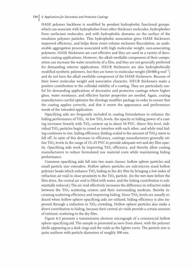
134 6 Applications for Decorative and Protective Coatings
HASE polymer backbone is modified by pendant hydrophobic functional groups,which can associate with hydrophobes from other thickener molecules, hydrophobesfrom surfactant molecules, and with hydrophobic domains on the surface of theemulsion polymer particles. This hydrophobic association gives HASE thickenersimproved efficiency, and helps them resist volume exclusion flocculation, an unde-sirable aggregation process associated with high molecular weight, non-associatingpolymers. HASE thickeners are cost effective and they are used in a variety of deco-rative coating applications. However, the alkali swellable component of their compo-sition can increase the water sensitivity of a film, and they are not generally preferredfor demanding exterior applications. HEUR thickeners are also hydrophobicallymodified synthetic polymers, but they are lower in molecular weight (50 000 g mol–1)and do not have the alkali swellable component of the HASE thickeners. Because oftheir lower molecular weight and associative character, HEUR thickeners make apositive contribution to the colloidal stability of a coating. They are particularly use-ful for demanding applications of decorative and protective coatings where highergloss, water resistance, and effective barrier properties are needed. Again, coatingmanufactures careful optimize the rheology modifier package in order to ensure thatthe coating applies correctly, and that it meets the appearance and performanceneeds of the intended application.
Opacifying aids are frequently included in coating formulations to enhance thehiding performance of TiO2. At low TiO2 levels, the opacity or hiding power of a coat-ing increases linearly with TiO2 content up to about 10 PVC. Above this level, indi-vidual TiO2 particles begin to crowd or interfere with each other, and while total hid-ing continues to rise, hiding efficiency (hiding scaled to the amount of TiO2) starts tofall off. In spite of this decrease in efficiency, coatings manufacturers generally uti-lize TiO2 levels in the range of 15–25 PVC to provide adequate wet and dry film opac-ity. Opacifying aids work by improving TiO2 efficiency, and thereby allow coatingmanufacturers to reduce formulated raw material costs while maintaining hidingperformance.
Common opacifying aids fall into two main classes: hollow sphere particles andsmall particle size extenders. Hollow sphere particles are sub-micron sized hollowpolymer beads which enhance TiO2 hiding in the dry film by bringing a low index ofrefraction air void in close proximity to the TiO2 particle. (In the wet state before thefilm dries, the central air void is filled with water, and the hiding contribution is sub-stantially reduced.) The air void effectively increases the difference in refractive indexbetween the TiO2 scattering centers and their surrounding medium, thereby in-creasing scattering efficiency and improving hiding. Since TiO2 levels are usually re-duced when hollow sphere opacifying aids are utilized, hiding efficiency is also im-proved through a reduction in TiO2 crowding. Hollow sphere particles also make adirect contribution to hiding, because their central air voids provide a certain amountof intrinsic scattering to the dry film.
Figure 6-2 presents a transmission electron micrograph of a commercial hollowsphere opacifying aid. The sample is presented as seen from above, with the polymershells appearing as a dark rings and the voids as the lighter cores. The particle size isquite uniform with particle diameters of roughly 300 nm.

6.2 Overview of Coating Formulations 135
Small particle size extenders are the other class of opacifying aids; acting as spac-ers, they increase the average distance between TiO2 particles in a film, thereby re-ducing crowding effects. The primary particle size of these specialized extenders isquite small (typically <0.5 µm), and the colloidal components of a coating need to beproperly formulated and stabilized in order for these materials to work effectively.
Biocides protect coatings from attack by microbial organisms. In the wet state, wa-ter based coatings possess the basic ingredients needed to support microbial growth:water, a source of carbon and nitrogen, and trace minerals. The use of anti-microbialagents, or biocides, is generally required to prevent water based paints from spoilingwhile being transported and stored. A variety of materials are used as in-can preserv-atives for water based coatings; in general, preservatives used in these applicationsare electrophilic compounds which function by reacting with nucleophilic groupswithin the cell or on the cell surface, thereby disrupting the function of vital cellularcomponents. Isothiazolones, and materials based on formaldehyde are most oftenused for this purpose, although other chemistries are used as well. Preservatives areused at low levels and generally do not affect the performance properties of a coating,unless they are inactivated and are unable perform their function.
Paint film mildewcides are commonly used in exterior coatings formulations toprevent defacement of the coating surface by mold and mildew. The surface of an ex-terior coating can accumulate nutrient compounds from the local environment; theymay leach out from the substrate, or they may be deposited by rain or from the at-mosphere. These materials, and the coating itself, support microbial growth on thepaint film surface. The microbial growth process can eventually lead to unsightlymildew and algae growth on the coating surface, seriously affecting decorative per-formance, and in severe cases, causing deterioration of the film itself. Coatingsbased on vinyl emulsion polymers have better resistance to microbial growth thantraditional alkyd coatings, but paint film mildewcides are usually included in exteri-or formulations to provide additional protection. (Apparently, the natural oil compo-nents of alkyd resins make them more readily metabolized by microorganisms, lead-ing to poorer intrinsic mildew resistance.) In the past, paint film mildewcides based
Fig. 6.2 Transmission Elec-tron Micrograph of a HollowSphere Opacifying Aid. Samplewas prepared by diluting poly-mer dispersion with water andthen drying a small quantity onan electron microscope samplegrid. Contrast was increased bystaining with RuO4. Particlesare approximately 300 nm indiameter. Polymer shellsappear as dark rings, and thehollow cores appear as thelight areas within the rings.
136 6 Applications for Decorative and Protective Coatings
on organomercury compounds provided cost effective protection in emulsion poly-mer coatings, but environmental and health concerns now strongly limit their use.Modern organic mildewcides have significantly improved environmental risk pro-files; they partition strongly into the polymeric domains of the coating, and if theyare released into the environment by the weathering process, they are present at ex-tremely low concentrations so that they can be broken down and metabolized by mi-croorganisms in the soil. The most common organic paint film mildewcides in usetoday are based on iodopropynylcarbamate, isothiazolone and chlorothalonilchemistries. Over the life of a film, these biocides slowly diffuse to the coating sur-face where they act to control microbial growth. Combinations of organic biocidesare sometimes used to provide increased protection against a broad spectrum of mi-croorganisms, and formulators commonly include zinc oxide in order to providelonger term protection from mildew growth. Used properly, modern paint filmmildewcides offer a safe and cost effective means to significantly extend the servicelife of exterior coatings.
Defoamers are used to prevent or to dissipate foam in coatings based on emulsionpolymers. Small air bubbles can be introduced into the liquid coating during themanufacturing or application processes. If these bubbles are stabilized or long lived,they can interfere with the efficiency of manufacturing, or leave unwanted voids inthe dried film. Unfortunately, the surfactants which are used in the manufacture ofemulsion polymers and water based coatings can also act to stabilize foam. De-foamers are used in a formulation to destabilize and to speed the breakup of foam inthe liquid coating. They are generally hydrocarbon or silicone based dispersions oremulsions which have limited compatibility with both the water and polymer phasesof the coating. This marginal incompatibility is an important factor in defoamer ef-fectiveness, and it must be properly balanced or it can result in film defects or loss ofactivity. While typically used at low levels (<1 % by weight), defoamers can signifi-cantly enhance the paint manufacturing process, as well as improving the applica-tion, appearance and performance characteristics of a coating.
Wetting aids are used to improve the ability of water based coatings to form defectfree films over a variety of substrates. Pure water has a high surface tension,73 mN m–1 [9], and while the surfactants present in a water based coating can reducethis to values in the 25–30 mN m–1 range, this may not be adequate to allow properwetting (and thus adhesion) to low surface energy substrates such as plastics or cer-tain re-paint surfaces. Also, surfactants can potentially interact with all the colloidalmaterials in a coating formulation (pigments, extenders, thickeners and defoamers)this can affect the amount of free surfactant available to reduce the surface tension.The equilibrated surface tension of a formulated coating will ultimately depend onthe complex distribution of surfactants molecules between these colloidal particles,the water phase and the coating surface, and the judicious use of wetting aids can beused to supplement colloidal stability and to promote proper wetting of the sub-strate. Typically wetting aids are surfactants or very low molecular weight oligomericpolymers. A wide variety of non-ionic and ionic surfactants are used, including hy-drocarbon and silicone based materials. They are generally selected by a combina-tion of previous experience and direct testing. Different wetting aids are used to ad-

6.3 Decorative Coatings 137
dress a variety of coating problems, including poor substrate adhesion, poor flow andleveling and poor color acceptance. While typically used at low levels (<1 %), they canplay a vital role in enabling water based coatings to meet specific appearance andperformance requirements.
6.3
Decorative Coatings
The primary role of decorative coatings is to enhance the esthetic appeal of homes,offices and other architectural structures by providing color, texture and sheen to interior and exterior surfaces. Decorative coatings are commonly classified by theirintended application, and these include interior wall, interior trim, exterior wall andexterior trim. The sheen level of the coating is also commonly characterized, andthese terms include flat, semi-gloss and gloss. These distinctions are not rigid or comprehensive, and coating manufactures commonly break these classes downfurther, or combine them, in order to enhance the marketability of their products.There are also many kinds of more specialized decorative coatings, such as masonryfinishes, clear and stain finishes for wood, floor paints for masonry and wood, drive-way sealers and arts and crafts finishes. Space limitations prevent a detailed discus-sion of these specialized coating applications, but much of the information we pres-ent here can be easily adapted to these coatings.
6.3.1
Emulsion Polymers in Decorative Coatings
The history of decorative coatings is long one, arguably extending back to prehistorictimes with paintings on the walls of cave dwellings. Focusing on more recent times,solvent borne drying oils and alkyds were the predominant polymer technologiesused throughout most of the twentieth century. However, rising environmental andhealth concerns, coupled with improvements in the performance of emulsion poly-mer coatings, have allowed water based coatings to move into the leading positionsin the decorative application areas. While emulsion polymers are now the marketleaders in most decorative applications, there are still a variety of technical issueswhich remain to be addressed by both raw material suppliers and paint manufactur-ers. Clearly, regulatory pressure to drive down VOC emissions continues to increasethroughout the world, and the challenges of balancing the often conflicting objec-tives of product cost, product performance and product differentiation remain.
6.3.2
Polymer Compositions used for Emulsion-based Decorative Coatings
A variety of thermoplastic emulsion polymers are used in decorative coating applica-tions, with VA-BAs, EVAs, styrene acrylics, and acrylics being most popular. VA-BAs,EVAs and styrene acrylics are commonly used for interior flat wall coatings, with the

138 6 Applications for Decorative and Protective Coatings
choices between them generally based on regional economic and performance char-acteristics. Acrylics and styrene acrylics are the preferred chemistries for exteriorapplications, again with regional economic factors and performance characteristicsdriving specific choices. Acrylics and styrene acrylics are both used for interior andexterior gloss and semi-gloss applications, while for interior semi-gloss applications,VA-BAs, acrylics and styrene acrylics are commonly used. These are generalizations,and the specific choices made by paint formulators are based on a complex mixtureof factors, including regional custom, local availability, raw material cost, and specif-ic performance needs.
6.3.3
Regional Distinctions in Decorative Coatings
There are significant regional distinctions in the formulation of decorative coatings.Differences in building materials and, consequently, the substrates to which coat-ings are commonly applied, underlie many of these distinctions. For example, NorthAmerica (NA), Australia – New Zealand (ANZ) and Scandinavia all have relativelyhigh levels of wood substrates, whereas masonry substrates are more common inEurope, Latin America (LA) and Asia. Substrate differences are a major factor in thepreference of acrylics for exterior wood applications in NA, ANZ and Scandinavia,the use of elastomeric wall coatings for masonry applications in Europe, and thechoice of styrene acrylics for masonry applications in LA and Asia.
The availability of supplies of low cost monomers is another important factor af-fecting the choice of polymer composition; this drives the use of VA-BA polymers forthe low cost interior flat segments of NA and ANZ, and the use of styrene acrylics fordecorative segments in Europe and Asia. In Latin America, decorative paints arecommonly designed for both interior and exterior applications, and styrene acrylicsand VA-BA polymers predominate in these markets. Regional economic factors alsoinfluence the choice of polymer used in coating applications: differences in raw ma-terial costs, and in labor costs, can affect how end users balance the higher initialcosts associated using a more durable, high performance coating, versus the higherdeferred costs associated with using a less durable coating having a more frequentre-paint cycle.
6.3.4
Market Size of Decorative Coatings
Decorative coatings, as defined here, account for roughly 40 % of worldwide coatingsproduction. The ratio can vary from country to country; heavily industrialized coun-tries have a relatively higher proportion of protective and product finishes, while lessindustrialized countries often have a higher proportion of decorative finishes. Start-ing with the world wide coating production estimate of 20 billion liters per year [1],and taking the fraction of decorative finishes to be 40 %, would give the total produc-tion of decorative coatings to be roughly 8 billion liters per year worldwide. Assum-ing that about 50 % of this is based on emulsion polymer technology leads to an esti-

6.4 Interior Decorative Coatings 139
mated annual production of about 4 billion liters of water-based decorative coatingsworld wide. We estimate the North American market to be a third of this value orabout 1.5 billion liters per year. If we estimate the average retail selling price to be$4–5 US per liter, this gives a total NA market value of $6–8 billion US per year fordecorative coatings. The volume of the European decorative coating market is rough-ly comparable in size to the North American market. Taking the annual Europeanproduction estimate to be also 1.5 billion liters per year, and assuming an averageretail selling price of roughly 4–5 Euros per liter, would give a total European marketvalue of about 6–8 billion Euros per year for decorative coatings. Again it is impor-tant to emphasize that these are very rough estimates, and are intended to give thereader a general picture of market size.
6.4
Interior Decorative Coatings
Interior decorative paints are designed to provide texture, sheen and color to the in-terior walls and ceilings of homes and offices. Paints based on emulsion polymertechnology now account for most of this segment. The popularity of water basedpaints in interior decorative applications is due to many factors, including their easeof use, low odor, fast dry, good appearance and color stability, and the ease of soapand water clean-up. Paints for this application are designed for a variety of specificapplications such as kitchen and bath, wall, trim and ceiling; they also provide differ-ent sheen levels such as flat, satin, semi-gloss and gloss. Coatings manufacturersproduce a wide variety products to meet the different needs of this large market seg-ment, and this in turn requires a correspondingly large number of formulations andraw materials. Because of space limitations, we will focus our discussion on two ofthe major segments of the interior decorative market, flat interior wall paints and in-terior trim enamels, and use them to highlight performance and formulation con-cepts of this market segment.
6.4.1
Key Performance Features
Interior flat wall coatings have a low or “flat” sheen, and they are usually formulatedwith an 85° gloss level below about 4 %. Low sheen levels are usually achieved by us-ing large particle size extenders at relatively high PVCs. While low sheen levels helpto hide defects in the substrate, differences in sheen and color are readily observablein these coatings, and thus sheen and color uniformity of the applied coating are keyperformance attributes. Good application characteristics are important as well; inte-rior flat wall paints are frequently spray applied in new construction applications,and are generally applied by roller in re-paint applications. Formulating with asso-ciative thickeners (typically HASE) can help reduce roller splatter, an important char-acteristic in re-paint applications. End users expect decorative coating to have goodhiding characteristics, and while true one-coat hiding remains an elusive goal, coat-

140 6 Applications for Decorative and Protective Coatings
ing manufacturers carefully balance hiding performance and cost in these formula-tions. Interior flat coatings also need to have good cleanability characteristics, sincethey are routinely applied to living areas (with higher potential for dirt and stains),and the coating’s ability to be easily cleaned can add significantly to its service lifeand user satisfaction.
Enamel coatings are frequently applied to trim surfaces such as doors, windowframes, decorative moldings around doors and windows, base boards, cupboardsand shelving. These surfaces often have a high level of day to day human contact anda tougher, more resistant coating is needed to provide substrate protection, film in-tegrity and optimum appearance characteristics. Trim enamels are frequently brushapplied so good flow and leveling characteristics are important. Enamels are gener-ally formulated at higher sheen levels, with values for semi-gloss and gloss coatingsranging from 30–85 % at 60°, respectively. They are applied over a variety of sub-strates, including aged alkyd, aged water based enamels, primed wood or metal, andthus they must have good adhesion characteristics. It is also desirable that the coat-ing’s hardness develop quickly so that objects can be placed on painted surfaceswithout marking the film. Trim enamels should also have good block resistance sothat adjacent painted surfaces can be pressed into contact without sticking to eachother. Finally, because they are applied in high use areas such as doors, windows andkitchen areas, trim enamels need good stain resistance and cleanability.
6.4.2
Interior Decorative Coating Formulations
Flat Interior Wall CoatingsCost is one of the most important factors for interior flat coatings and drives many ofthe choices in formulations and raw materials. Vinyl acetate and styrene basedcopolymers are most frequently used as binders for this market and cost considera-tions also drive the use of relatively high levels of low cost extenders. Thus, PVCs aregenerally high, and are usually above CPVC. Opacifying aids are commonly used tohelp achieve high hiding levels, and they also help to lower raw material costs by re-ducing TiO2 levels. Rheology modifiers are chosen to provide the desired rheologyprofile, with HASE and cellulosic thickeners being most commonly used. A coalesc-ing agent is usually included to enhance film formation, although recently developedbinders for interior flat coatings can often be formulated with very little or no addedcoalescent. Propylene glycol is commonly used as a pigment grinding aid, and to im-prove the freeze thaw resistance of the wet paint during storage. Finally, anionic andnon-ionic surfactants are commonly added to optimize colloidal stability and en-hance color development and uniformity. Table 6-1 provides an example of a typicalinterior flat coating formulation.
Interior EnamelsPolymer performance plays a more significant role in the formulation of enamelcoatings than in flat coatings, since the polymer component makes up a higher vol-ume fraction of the dried film. Acrylic and styrene acrylic emulsion polymers are
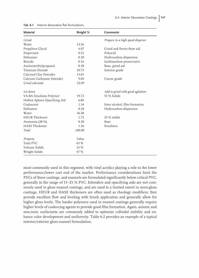
6.4 Interior Decorative Coatings 141
most commonly used in this segment, with vinyl acrylics playing a role in the lowerperformance/lower cost end of the market. Performance considerations limit thePVCs of these coatings, and enamels are formulated significantly below critical PVC,generally in the range of 15–25 % PVC. Extenders and opacifying aids are not com-monly used in gloss enamel coatings, and are used to a limited extent in semi-glosscoatings. HEUR and HASE thickeners are often used as rheology modifiers; theyprovide excellent flow and leveling with brush application and generally allow forhigher gloss levels. The harder polymers used in enamel coatings generally requirehigher levels of coalescing agents to provide good film formation. Again, anionic andnon-ionic surfactants are commonly added to optimize colloidal stability and en-hance color development and uniformity. Table 6-2 provides an example of a typicalinterior/exterior gloss enamel formulation.
Tab. 6-1 Interior decorative flat formulation.
Material Weight % Comments
Grind Prepare in a high speed disperserWater 13.56Propylene Glycol 4.07 Grind and freeze-thaw aidDispersant 0.52 Polyacid Defoamer 0.18 Hydrocarbon dispersionBiocide 0.16 Isothiazolone preservativeAminomethylpropanol 0.18 Base, grind aidTitanium Dioxide 10.73 Interior gradeCalcined Clay Extender 13.65Calcium Carbonate Extender 9.04 Coarse gradeGrind sub-total 52.09
Let down Add to grind with good agitationVA-BA Emulsion Polymer 19.72 55 % SolidsHollow Sphere Opacifying Aid 6.84Coalescent 1.34 Ester alcohol, film formationDefoamer 0.18 Hydrocarbon dispersionWater 16.58HEUR Thickener 1.72 25 % solidsAmmonia (28 %) 0.18 BaseHASE Thickener 1.36 Emulsion Total 100.00
Property ValueTotal PVC 63 %Volume Solids 33 %Weight Solids 47 %

142 6 Applications for Decorative and Protective Coatings
6.4.3
Standard Application and Performance Tests
Many specialized tests have been developed to measure the application, appearanceand resistance properties of interior decorative coatings. The reader is referred to the specific ASTM and ISO test methods given in Tab. 6-3, and the cited refer-ences [13–14] for a more detailed description of test method protocols. Our objectivein this section, and in the subsequent application and performance test sections, willbe to identify the key performance features and to give the reader an overview of howthese tests are conducted.
Decorative coatings are often stored for long periods of time under sub-optimumconditions before they are sold or applied. In the warmer regions of the world, coat-ings are frequently stored in warehouses where temperatures can reach 45 °C for ex-tended periods of time. In the colder regions of the world, coatings can be subjectedto repeated freeze-thaw cycling when stored at an unheated job site. Heat age andfreeze-thaw stability testing protocols have been developed to assess the storage sta-bility of coating products. Heat Age Stability is tested by placing the paint in an ovenfor a specific time and temperature, and then testing the coating for key performance
Tab. 6-2 Interior/exterior decorative gloss enamel.
Material Weight % Comments
Grind Prepare in a high speed disperserPropylene Glycol 3.36 Grinding aidWater 2.43Biocide 0.10 Isothiazolone preservativeDispersant 1.12 Hydrophobically modified polyacidSurfactant 0.10 Non-ionic pigment wetting aidDefoamer 0.02 Silicone emulsionTitanium Dioxide 21.28 Universal GradeGrind sub-total 28.39
Let down Add to grind with good agitationAcrylic Emulsion Polymer 50.67 Specialized gloss enamel vehicleWater 15.16Diethylene glycol butyl ether 0.58 Co-solvent Coalescent 2.50 Ester alcohol, film formationPhosphate Surfactant 0.09 Wetting AidHEUR Thickener A 2.36 20 % solidsHEUR Thickener B 0.19 25 % solidsDefoamer 0.05 Silicone emulsionTotal 100.00
Property ValueTotal PVC 21 %Volume Solids 32 %Weight Solids 45 %
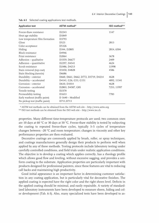
6.4 Interior Decorative Coatings 143
properties. Many different time-temperature protocols are used; two common onesare 10 days at 60 °C or 30 days at 50 °C. Freeze-thaw stability is tested by subjectingthe coating to repeated freeze-thaw cycles, typically 3–5 cycles of temperaturechanges between –20 °C and room temperature; changes in viscosity and other keyperformance properties are then evaluated.
Decorative coatings are commonly applied by brush, roller, or spray techniques,and coatings manufacturers generally design their products to perform well whenapplied by any of these methods. Testing protocols include laboratory testing undercarefully controlled conditions, and field trials under realistic application conditions.The objective is to develop a coating which applies correctly, has a rheology profilewhich allows good flow and leveling, without excessive sagging, and provides a uni-form coating to the substrate. Application properties are particularly important withproducts designed for professional painters, since these features are vital to reducingcall backs and maintaining high productivity.
Good initial appearance is an important factor in determining customer satisfac-tion in any coating application, but is particularly vital for decorative finishes. Theapplied coating is expected have the right color and the right sheen level. Defects inthe applied coating should be minimal, and easily repairable. A variety of standard-ized laboratory instruments have been developed to measure sheen, hiding and col-or development (Tab. 6-3). Also, many specialized tests have been developed to as-
Tab. 6-3 Selected coating applications test methods.
Application test ASTM method* ISO method**
Freeze-thaw resistance D2243 1147Heat age stability D1849Low temperature film formation D3793Gloss D523 2813Color acceptance D5326Hiding D344, D2805 2814, 6504Block resistance D4946Print resistance D2064 3678Adhesion – qualitative D3359, D6677 2409Adhesion – quantitative D2297, D4541 4624Scrub resistance D2486, D4213 11998Stain removal (top coat) D3450, D4828 4586Stain blocking (tannin) D6686Durability – exterior D660, D661, D662, D772, D3719, D4214 4628Durability – accelerated D4141, G26, G53, G151 4892, 11341Corrosion – exterior D610, D1014 4628Corrosion – accelerated D2803, D4587, G85 7253, 11997Tensile testing D2370Permeability testing D1653 7783Early washout (traffic paint) D 1640 – ModifiedNo pickup test (traffic paint) D711,D713
** ASTM test methods can be obtained from the ASTM web site – http://www.astm.org** ISO test methods can be obtained from the ISO web site – http://www.iso.ch

144 6 Applications for Decorative and Protective Coatings
sess appearance properties under specific application conditions. For example thecolor rub-up test assesses the color variability of a coating when applied by brush orroller application techniques. Since large interior wall areas are usually painted bybrush application around the perimeters, and then filled in by roller application tothe center sections, variations in color uniformity can have a significant impact onend user satisfaction. In laboratory testing of this property, a draw-down of uniformfilm thickness is first applied, and then a section of the coating is either rubbed withthe finger or brushed until the coating starts to dry. Color differences between thelow shear rate draw-down region and the high shear rate rub up or brushed regionare then assessed subjectively, or measured quantitatively with a color spectropho-tometer. Problems in this area are generally related to poor colloidal stability; a light-ly flocculated pigment dispersion can be temporarily dispersed by the high shearconditions of brushing, and this can result in a color which appears different fromadjacent areas coated under the lower shear rate of roller application.
Resistance propertiesIn contrast to the appearance and applications properties of a coating, resistanceproperties are not assessed by the user during and immediately after the application,but rather, they impact user satisfaction by affecting the service life of the coating.Laboratory testing plays a key role in assessing the resistance properties of coatings,because it provides a controlled and accelerated measure of performance featureswhich may take years to become evident in actual end use applications. Adhesion isa key performance factor and several tests have been developed to measure this pa-rameter. All adhesion tests follow the general protocol of applying the test coating toa defined substrate such as chalky or aged alkyd, steel or aluminum, allowing thecoating to dry for a specified time, and then testing the adhesion of the applied coat-ing by attempting to separate it from the substrate. Adhesion can be tested under wetor dry conditions (wet adhesion is usually a more severe test than dry adhesion), andthe coating is usually scored or cut in order to minimize the confounding effects offilm integrity. Cohesive failure occurs when the coating remains bound at thefilm–substrate interface and separation occurs within the coatings itself, or by de-struction of the substrate. This is generally indicative of good adhesion performance,but it can sometimes be misinterpreted when a coating has extremely poor film in-tegrity (giving a false positive reading). Adhesive failure occurs when the appliedcoating separates from the substrate at the interface between the coating and thesubstrate. Failures of this type can be assessed via subjective or quantitative meas-urements, such as using knife peel, cross hatch/tape pull, or a quantitative measure-ment of the force to peel. While it is desirable to have a coating exhibit cohesive fail-ure in lab tests, coatings which exhibit adhesive failure often show good adhesionperformance in actual exposure testing. Experience and careful comparisons againstknown standards are generally required in order to obtain useful performance pre-dictions in these cases.
The cleanability of a coating is generally assessed by stain resistance or scrub tests.In the stain resistance test, the coating is allowed to dry for a specified time (usuallya week) and then common staining materials such as coffee, tea, fruit juice, mustard,

6.4 Interior Decorative Coatings 145
ketchup, pencil, pen or felt tip marker are applied to the surface. After a specifiedcontact time, the coating is washed with a cleaning formulation and then is rated forstain removal relative to controls. The scrub test assesses cleanability differently, andmeasurers the ability of a coating to resist abrasion by a stiff brush and an abrasivecleaner, or cleaning solution. A coating of defined thickness is applied to a vinylchart and dried for a specified time, usually a week. A specialized scrub testing ma-chine is used to scrub the coating with a brush and a standardized abrasive medium.The operator assesses the number of scrub cycles needed to wear through the coat-ing to the substrate. In another variation of the scrub test, the test coating is placed inthe testing machine for a fixed number of cycles using either the abrasive medium ora cleaning solution, and then cleaned and dried. Performance is assessed by meas-uring the weight of coating lost during the scrub process. Both tests are subject tohigh levels of variability and carefully controlled experiments are needed to produceaccurate and reproducible results.
Block resistance is a measure of a coating’s ability to resist destructive self adhe-sion when placed into contact with itself. This is an important feature for coatingswhich are applied to windows and doors, since in these components, painted sur-faces are placed in contact in routine operation. Dry time and contact pressure areimportant factors affecting block resistance and are the primary variables which arecontrolled in laboratory testing. The coating is cast on a non-rigid substrate such as acoated paper chart, and allowed to dry under controlled conditions for a specifiedtime (typically ranging from 8 h to 4 weeks). Small squares of the coated substrateare then cut out and placed with the coated sides facing together. A defined pressure(generally in the form of a 0.5 kg weight on a surface area of approximately 5 cm2) isapplied for a specified period of time and temperature (typically 12 h at 25 °C or 4 hat 50 °C). The test squares are then pulled apart and rated subjectively for self adhe-sion. Ideally, the two test squares separate with minimal force, leaving no film dam-age. Failure is noted when the film is visibly damaged upon separation. In a variationof this test, the coating can be applied to a rigid substrate such as glass or metal, andthese test areas are placed together, under pressure, as described above. The forcenecessary to separate the test areas is then measured quantitatively.
The print resistance test measures the ability of a coating to resist permanent im-printing caused by the placement of heavy objects, such as books or vases, on a hori-zontal coated surface. In this test, a coating is cast onto a metal substrate, and then aheavily textured object, such as a rough cloth is placed on the coated surface with adefined pressure (typically about 1 kg per 5 cm2). The test is allowed to progress for aspecified time and temperature (usually one week at 25 °C, or one day at 50 °C), andthen the coating is evaluated subjectively against controls for its ability to resist per-manent marking or defacement.

146 6 Applications for Decorative and Protective Coatings
6.5
Exterior Decorative Coatings
Exterior decorative coatings are used to provide aesthetic and protective features tothe exterior walls and trim of houses, apartments and offices. They share many ofthe application, appearance and resistance features characterizing interior decorativecoatings, with the obvious and important difference that they are expected to providethese features while being subjected to the deleterious effects of UV radiation andweathering. In addition, exterior decorative coatings are expected to protect theirsubstrates from the harmful effects of weathering for the lifetime of the coating.Historically, alkyd and oil based coatings were commonly used in exterior decorativeapplications, but over the past 30 years coatings based on emulsion polymers haveadvanced and are now the preferred technology for this application. The primaryreason for this is the superior durability of acrylic emulsion polymers (and to a lesserextent vinyl-acrylic and styrene-acrylic polymers) in exterior applications. Alkyd andoil based coatings rely on oxidative cure processes to develop resistance properties.While the cure processes are quite efficient, they can eventually lead to film embrit-tlement and subsequent cracking over dimensionally unstable substrates. Addition-ally, most alkyd resins are made by the esterification of phthalic anhydride with un-saturated fatty acids or natural drying oils. The UV absorption characteristics ofthese materials make them quite susceptible to UV degradation, leading to poor tintretention and premature chalking. Finally, the ester linkages of oil and alkyd basedcoatings are susceptible to alkaline based hydrolysis, a polymer degradation processwhich can be accelerated by the basic pH conditions present in many masonry appli-cations, particularly over freshly prepared concrete. Acrylic based polymers are moreresistant to these different degradation processes and, consequently, have becomethe performance standards for exterior decorative coatings.
6.5.1
Key Performance Features
Exterior durability is the key factor which differentiates the performance of exteriordecorative coatings. This is primarily manifested in three important areas: tint andgloss retention – the ability of a coating to maintain its original color and gloss levelduring exposure, chalk resistance – the ability of a coating to resist the surface pow-dering caused by UV and moisture induced polymer degradation, and resistance tocracking and adhesion loss – the ability of a coating to resist grain cracking and thesubsequent flaking and loss of adhesion when applied over wood substrates. Gooddirt pick-up resistance is also important; the coating should be resistant to darkeningcaused by adsorption of dirt and soot from the external environment. Adhesion to avariety of architectural substrates is also an important performance feature, particu-larly in re-paint applications where weathered substrates present particular chal-lenges. Because exterior coatings are generally viewed from a distance, appearanceproperties such as flow and leveling are somewhat less important than they are inmany interior applications. Of course, most of the other performance features de-
6.5 Exterior Decorative Coatings 147
scribed above for interior decorative coatings also apply to their exterior counter-parts.
6.5.2
Exterior Decorative Coating Formulations
Acrylic emulsion polymers are generally preferred for exterior decorative applica-tions because of their good exterior durability characteristics. Styrene acrylics andvinyl acrylics are also popular, particularly in regions of the world where lower laborcosts reduce the economic barrier to a more frequent re-paint cycle. In contrast to in-terior flat paints, exterior flat paints are generally formulated below CPVC in order toprovide improved durability. Because good moisture resistance generally is requiredfor exterior applications, cellulosic and HEUR thickeners are generally chosen asrheology modifiers for exterior applications; cellulosics are commonly used in exter-ior flat formulations, while HEURs are commonly used in gloss and semi-glossformulations. Durable grades of TiO2, coated with inorganic materials to provideimproved UV resistance, are generally chosen for exterior applications. The choice ofextenders can also have a significant impact on the performance of exterior coatings.Based on our experience, the tint retention and chalk resistance of exterior flat coat-ings can be enhanced by favoring the use of coarse silica or nephiline syenite overclays. Calcium carbonates generally have good tint retention, but they can degrade inregions with acid rain, sometimes leading to poor dirt pick-up resistance. Carbonatescan also can show frosting (the appearance of a hard white exudate, visible on tintedfilms) in horizontal face down applications. Finally, a paint film mildewcide is gen-erally included in exterior formulations, particularly in flat and satin formulations, tominimize mildew growth on the coating after application. A typical formulation foran exterior flat decorative coating is given in Tab. 6-4.
6.5.3
Standard Application and Performance Tests
Exterior exposure testing is the most direct and reliable method to evaluate the dura-bility of exterior decorative coatings. The most representative and general exposureprotocol is to actually apply the coating to test homes or buildings, and to then evalu-ate the performance over a long period of time. However, the cost and logistics ofsuch large scale trials limit their use, and the vast majority of exterior exposure test-ing is done via controlled exposure experiments carried out at established exposuresites around the world. Most raw material suppliers and many coating manufactur-ers have set up their own exposure sites, or use commercial exposure services, toprovide this capability. A typical experimental design for an exposure experimentwould include experimental and control coatings which are applied, in replicate, totest areas (on the order of 15 cm × 30 cm) over a variety of representative substrates.The choice of substrates depends on the intended market segment and region, butnormally would include several different types of wood and masonry in both newand re-paint applications. In the Northern hemisphere, South vertical exposures are
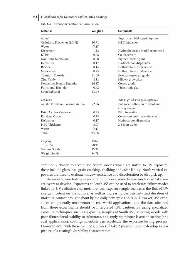
148 6 Applications for Decorative and Protective Coatings
commonly chosen to accentuate failure modes which are linked to UV exposure;these include gloss loss, grain cracking, chalking and color fading. North vertical ex-posures are used to evaluate mildew resistance and discoloration by dirt pick up.
Exterior exposure testing is not a rapid process; some failure modes can take sev-eral years to develop. Exposures at South 45° can be used to accelerate failure modeslinked to UV radiation and moisture; this exposure angle increases the flux of UVenergy incident on the sample, as well as increasing the intensity and duration ofmoisture contact brought about by the daily dew cycle and rain. However, 45° expo-sures are generally uncommon in real world applications, and the data obtainedfrom these experiments should be interpreted with caution. By using specializedexposure techniques such as: exposing samples at South 45°, selecting woods withpoor dimensional stability as substrates, and applying thinner layers of coating (onecoat applications), coatings scientists can accelerate the exposure testing process.However, even with these methods, it can still take 2 years or more to develop a clearpicture of a coating’s durability characteristics.
Tab. 6-4 Exterior decorative flat formulation.
Material Weight % Comments
Grind Prepare in a high speed disperserCellulosic Thickener (2.5 %) 10.71 HEC thickenerWater 7.17Dispersant 1.52 Hydrophobically modified polyacidKTPP 0.08 Co-dispersantNon-Ionic Surfactant 0.08 Pigment wetting aidDefoamer 0.17 Hydrocarbon dispersionBiocide 0.14 Isothiazolone preservativeMildewcide 0.25 Isothiazolone mildewcideTitanium Dioxide 21.09 Exterior universal gradeZinc Oxide 2.11 Mildew protectionNepheline Syenite Extender 16.87 Coarse gradeFunctional Extender 0.42 Thixotropic clayGrind sub-total 60.64
Let down Add to grind with good agitationAcrylic Emulsion Polymer (60 %) 22.86 Enhanced adhesion to alkyd and
chalky re-paintEster Alcohol Coalescent 0.83 Film formationEthylene Glycol 0.25 Co-solvent and freeze-thaw aidDefoamer 0.17 Hydrocarbon dispersionHEC Thickener 8.07 2.5 % in waterWater 7.17Total 100.00
Property ValueTotal PVC 50 %Volume Solids 35 %Weight Solids 54 %
6.6 Elastomeric Wall Coatings 149
Accelerating the process for assessing the durability of exterior coatings is of obvi-ous interest to raw material suppliers, coating manufacturers and end users. This iscurrently an area of active research and a variety of efforts are under way to improvethe predictive ability of accelerated weathering protocols [15]. While a variety of ex-posure instruments and devices have been developed, and are commonly used toprovide accelerated exposure information, we have found that these instruments donot always provide information consistent with exterior exposures. Accelerated expo-sure devices have proven to be most useful when evaluating specific failure modes,and comparing the performance of coatings of similar composition, applied over di-mensionally stable substrates.
6.6
Elastomeric Wall Coatings
Specialized elastomeric wall coatings were first introduced into European markets inthe early 1980s. Their function is to enhance the appearance and durability of exteri-or masonry surfaces present on large buildings such as apartments, hotels and of-fices. These types of structures often have large uniform surfaces which can be dis-figured by small cracks and fractures, caused by uneven thermal expansion and con-traction. Elastomeric coatings improve the appearance of masonry surfaces by cover-ing these small cracks with a smooth elastic film, and they enhance the durability ofmasonry substrates by preventing the intrusion of water into these defects.
6.6.1
Key Performance Features
Elastomeric wall coatings are designed provide a high quality decorative and protec-tive finish for large masonry surfaces. The elastic character of these coatings, alongwith the use of thicker applied films, allows them to bridge cracks in the substrateand to stretch and shrink with thermally driven building movement. Elastomericcoatings also prevent the penetration of wind driven rain and water into the substrateby sealing these cracks, thus improving the durability of the underlying masonry ma-terial. Emulsion polymers used for elastomeric wall coatings generally have low Tg
(typically less than –20 °C) in order to provide the elastic character needed for effec-tive crack bridging. The use of such soft polymers would normally lead to coatingswith poor dirt pick up resistance and tackiness, but proprietary technologies are usu-ally employed to address these problems. Elastomeric coatings can significantly en-hance the durability of many masonry surfaces, and because masonry constructionis widely used around the world, the use of elastomeric wall coatings has grown sig-nificantly over the past 20 years.

150 6 Applications for Decorative and Protective Coatings
6.6.2
Typical Elastomeric Wall Coating Formulations
Elastomeric coatings are formulated to yield tough films which maintain a balance oftensile strength and elongation characteristics across a broad temperature range(–10 to +30 °C). These coatings are generally formulated at relatively low PVCs (typi-cally in the range of 30–45 %) to provide the dried film with good elasticity and bar-rier properties. These coatings are formulated with relatively low levels of hiding pig-ments, since thick coatings are generally utilized. They are usually extended withfillers such as calcium carbonate. Volume solids are typically high, in the in range of50 % to 60 %, in order to provide for thicker dried films. For optimum long-term per-formance, it is recommended that the total dry film thickness be in the range of 300to 500 µm, much thicker than typically used in architectural applications. Coatings ofthis thickness need a carefully optimized rheology profile in order to prevent saggingduring the application and drying processes. Cellulosics, either alone or in combina-tion with HEUR thickeners, are generally preferred for this application. An effectivepaint film mildewcide is also need in order to prevent discoloration of the coatingsurface by mildew growth. Elastomeric wall coatings are generally formulated to beapplied by professional painters using either roller or spray application techniques.A typical elastomeric coating formulation is given in Tab. 6-5.
Tab. 6-5 Elastomeric wall coating formulation.
Material Weight % Comments
Grind Prepare with high speed disperserWater 5.67Ethylene Glycol 2.75 Grind aid and freeze-thawDispersant 0.44 PolyacidKTPP 0.09 Co-dispersantDefoamer 0.35 Hydrocarbon dispersionTitanium Dioxide 6.20 Exterior GradeCalcium Carbonate Extender 26.12 Fine gradeZinc Oxide 2.21 Mildew protectionGrind sub-total 43.84
Let down Add to grind with good agitationSurfactant 0.55 Wetting aid, non-ionicAcrylic Emulsion Polymer 54.20 Specialized elastomeric vehicleDefoamer 0.09 Hydrocarbon dispersionMildewcide 0.18 Isothiazolone classHEC Thickener 0.27 SolidWater 0.89Total 100.00
Property ValueTotal PVC 31 %Volume Solids 49 %Weight Solids 61 %

6.7 Primer Coatings 151
6.6.3
Standard Application and Performance Tests
The tensile and elongation properties of an elastomeric coating are important performance features which characterize the coating’s ability to bridge cracks in thesubstrate. These properties are commonly evaluated in the laboratory at ambient andbelow ambient temperatures by use of a tensile testing instrument (Instron type orequivalent). Testing is performed at a constant rate of jaw separation with load cellsadequate to measure the tensile forces generated. Testing sample dimensions areusually about 500 µm thick × 2 cm long × 1 cm wide, and samples are cut with a diefrom a dried film which was drawn down over a Teflon release plate. The sample isfastened between the jaws of the tester and is stretched apart at a constant strain rateuntil it breaks. Values for the percent elongation and tensile strength at break arethen calculated. These values depend somewhat on the strain rate used; generally,lower strain rates yield higher values for elongation, coupled with lower values fortensile strength at break.
The permeability of an elastomeric coating is crucial for determining whether thecoating will allow adequate passage of water vapor through the coating. In the labo-ratory, permeability is evaluated by sealing a dried paint film of specified thicknessover a cup of water and placing the assembly in a constant temperature and humidi-ty room. Water loss from the cup, through the film, is measured by mass differenceover the course of one week. Permeability is then calculated from the rate at whichwater is lost through the film.
6.7
Primer Coatings
Primer coatings are used to provide a functional boundary layer between the sub-strate and the topcoat. Coating manufacturers design a variety of specialized primersto enhance total system performance for a variety of coating applications. Primersgenerally provide many or all of the following features:(i) they promote effective adhesion to a variety of substrates;(ii) they prevent the transport of a variety of different types of colored stains from
the substrate to the topcoat;(iii) they enhance corrosion resistance;(iv) they serve as a flexible linkage between dimensionally unstable substrates and
the topcoat; and(v) they reduce irregularities and imperfections in the substrate, providing a
smoother and more uniform surface for the topcoat.Decorative and protective primers generally have demanding performance specifica-tions, and are usually formulated at relatively low PVCs and high volume solids.They usually are not designed to provide high hiding or intrinsic weathering resist-ance, since the topcoat can be independently optimized to provide these and otherperformance features.

152 6 Applications for Decorative and Protective Coatings
6.7.1
Key Performance Features
Primer vehicles based on emulsion polymer technology were introduced in the1970s and have shown a steady increase in market share over the past 30 years. Theyare used in a variety of exterior and interior coating applications. Stain blockingprimers are one of the most popular types, and are used to prevent discoloration oftopcoats by a variety of materials, including tannin stains from wood, children’smarker stains, water stains and nicotine stains. Water based primers generally blockthe transport of stains by two principle mechanisms:(i) the primer acts as a physical barrier and blocks the migration of stains from the
substrate to the topcoat (this is similar to the way in which solvent based primersblock stain transport); and
(ii) the primer is formulated with specialized ingredients, such as zinc oxide or oth-er functionalized extenders, which lock (by interacting with) stain molecules intothe film.
While the stain may be visible at the surface of the primer coating after drying, it iseffectively locked into the film and does not lead to discoloration of the topcoat.Binders for stain blocking primers are usually based on relatively hydrophobic emul-sion polymers with acrylic or styrene acrylic compositions. Primers are expected tohave excellent adhesion, and water based primers are formulated to adhere to a vari-ety of substrates including metal, wood, and chalky or aged re-paint surfaces. Sincethis level of performance may not be needed, or achievable, in many topcoat formu-lations, the use of specialized primers offers a flexible and cost effective way to meetthe performance needs of many different coating applications with a limited numberof optimized topcoat products.
6.7.2
Primer Formulations
Primers based on emulsion polymers typically are formulated with PVCs in therange 25 to 45 % and volume solids in the range 30 to 40 %; lower PVCs and highervolume solids formulations are preferred because these characteristics providetighter and more flexible films. Primer formulations frequently (but not always)contain some type of reactive pigment or specialized extender to enhance per-formance features: stain blocking primers frequently utilize functionalized exten-ders to lock stains while anti-corrosive primers utilize reactive pigments to passivateferrous substrates. The performance characteristics of primers can be greatly affect-ed by the choice of thickener and dispersant; HEUR rheology modifiers along withrelatively hydrophobic dispersants are generally preferred in this application. In gen-eral, effective primers are formulated with a high degree of colloidal stability and re-duced levels of water sensitive materials in order to improve performance character-istics. Table 6-6 illustrates a typical formulation used in stain blocking primer appli-cations.

6.7 Primer Coatings 153
6.7.3
Standard Application and Performance Tests
Application testing for stain blocking primers is focused on the ability of the primerto block stains and to provide a suitable substrate for the topcoat. Laboratory testingfor tannin stain resistance is performed by applying the primers, along with a suit-able topcoat, to wooden panels with high tannin levels such as western red cedar orredwood. The panels are allowed to dry for a short time and they are then placed in ahigh moisture environment such as a fog box or mist chamber. Because of the highdegree of panel to panel variability inherent with a natural substrate such as wood, acareful experimental design (comparisons on the same panel, replication, etc.) isneeded to obtain meaningful results. After the panels are removed from the fog boxand allowed to dry, the performance is rated by a visual comparison against the con-trols. Laboratory testing of marker stain resistance is done in a similar manner; the
Tab. 6-6 Stain blocking decorative primer formulation.
Material Weight % Comments
Grind Prepare in a high speed disperserWater 4.90Biocide 0.15 Isothiazolone preservativeDispersant 0.89 Hydrophobically modified polyacidDefoamer 0.17 Hydrocarbon dispersionTitanium Dioxide 14.67 Exterior gradeCalcium Carbonate Extender 4.90 Coarse gradeDispersant 0.21 Acrylic acid typeZinc Oxide 1.18 Functional extender – stain blockingGrind sub-total 27.07
Let down Add to grind with good agitationHEUR Thickener A 0.25 25 % solidsAcrylic Emulsion Polymer 65.16 Specialized primer vehicleEster Alcohol Coalescent 1.40 Film formationEthylene Glycol 2.73 Co-solvent and freeze-thaw aidBiocide 0.19 Isothiazolone mildewcideDefoamer 0.39 Hydrocarbon dispersionThickener B 0.20 HASE (30 %)Ammonia (28 %) 0.10 pH adjustmentWater 1.24HEUR Thickener A 0.25 25 % solidsHEUR Thickener B 1.03 20 % solidsTotal 100.00
Property ValueTotal PVC 19 %Volume Solids 37 %Weight Solids 49 %
154 6 Applications for Decorative and Protective Coatings
performance of primer-topcoat combinations are evaluated for their ability to resistdiscoloration relative to a set of pass and fail controls. Testing is usually carried outwith several water based and solvent based markers, which are applied to draw-downcharts. The trial primers are then drawn down over the test area, allowed to dry for ashort period (usually 2–4 h) and then coated with a suitable topcoat. Samples dryovernight and are then rated relative to controls by a visual comparison.
6.8
Protective and Industrial Coatings
The distinctions between protective and decorative coatings are often a matter of de-gree, and for our purposes, we will define protective and industrial finishes as coat-ings which are applied to large industrial structures, such as bridges and factories, orto products produced in an industrial production process. We will not include auto-motive coatings in our current discussion, since they are covered in Chapter 7 of thisvolume. Even with these limitations, there are a great number of different types ofapplication areas which use protective or industrial coatings; these include coatingsfor industrial structures, machinery and equipment, metal containers, wood furni-ture and flat stock, and more specialized applications such as coil coatings, marinecoatings and traffic marking coatings. The performance requirements of coatingsdesigned for protective and industrial applications are generally more demandingthan those of decorative coatings. Because of this, and the wide variety of applica-tions, the shift to coatings based on waterborne emulsion polymers has not been aspronounced as it has been in the decorative area. Solvent borne coatings are the his-torical market leaders in protective and industrial coating markets, and they still holdthis position in most applications. However, new developments in polymer designand formulation technologies have allowed waterborne finishes to make significantinroads into many areas of protective and industrial coatings. This, coupled with anincreasingly stringent regulatory environment, has led to significant growth in theuse of waterborne coatings for these applications.
6.8.1
Copolymers used in Protective and Industrial Coatings
A variety of synthetic polymer resins are used in coatings for protective and industrialfinishes, with solvent-borne alkyds, acrylics, urethanes, epoxies and polyesters beingmost common. Recently, high solids coatings (based on solvent borne polymersdesigned for formulation with low levels of solvent) and powder coatings have alsomade significant inroads into the protective and industrial coatings areas. In the con-text of waterborne coatings, acrylic emulsion polymers are the most common com-positions chosen for these applications, although significant amounts of waterborneepoxies, polyurethanes and emulsified alkyds are also used. Acrylic emulsion poly-mers for protective and industrial coating applications are generally designed with Tg
in the range 30 to 60 °C, significantly higher than binders used for decorative appli-

6.8 Protective and Industrial Coatings 155
cations. Thermosetting acrylic systems, which utilize melamine or other types ofcrosslinking chemistry, are also used in many factory applied, oven bake applica-tions. Since most protective and industrial finishes are applied to dimensionally sta-ble substrates, polymers with harder compositions can be utilized in order to provideimproved performance characteristics, without suffering the drawbacks usually as-sociated with using higher Tg polymers in many decorative applications.
6.8.2
Market Size
Based on the analysis presented in the earlier sections of this chapter, coatings usedin protective and industrial (non-decorative) applications represent about 60 % of an-nual world wide production, or roughly 12 billion liters per year. Assuming that au-tomotive and other applications outside the traditional finish applications representroughly a third of this value, we estimate the world wide annual production to be ap-proximately 8 billion liters per year for protective and industrial finishes, as we havedefined them. North American production is estimated to be about 1/4 to 1/3 of thisvalue, or roughly 2 to 3 billion liters per year. The penetration of waterborne coatingshas been less in these markets than in decorative areas; assuming a value of 25 %yields an estimated annual production rate for waterborne protective and industrialfinishes to be on the order of 2 billion liters world wide, and 0.5–0.7 billion liters peryear in North America. Again, we emphasize the approximate nature of these esti-mates and provide them to give the reader a general idea of market size.
6.8.3
Industrial Maintenance Coatings
Industrial maintenance coatings are designed to provide corrosion control and ex-tend the service life of large metal and concrete structures associated with manufac-turing, chemical processing and transportation. Typical applications include bridges,storage towers, water tanks, chemical plants, oil refineries, water treatment plants,and electrical power plants. Solvent borne coatings predominate in this high per-formance application, with alkyds historically holding the largest share, and epoxiesand urethanes showing very good growth in recent decades due to their strong per-formance profiles. The use of waterborne coatings in the light and medium dutysegments of this market has grown significantly over recent years, and we estimatethey now account for approximately 20 % of these segments in North America.
6.8.4
Key Performance Features
Early water based coatings for industrial maintenance applications utilized polymersdeveloped for exterior decorative coatings. Although these polymers provided goodgloss and tint retention in exterior applications, they were not optimized to providegood corrosion or chemical resistance. Better barrier properties were needed to im-

156 6 Applications for Decorative and Protective Coatings
prove these performance features, and specialized maintenance binders were devel-oped by reducing polymer molecular weight (to promote improved film formation)and utilizing more hydrophobic compositions (to provide better resistance to waterand ion transport). A properly balanced composition is needed for optimum per-formance in maintenance applications; all acrylic polymers provide excellent dura-bility characteristics, but are generally supplemented with more hydrophobicmonomers such as styrene or ethylhexyl acrylate in order to provide improved barri-er properties and corrosion resistance. Acrylonitrile is sometimes incorporated inorder to improve chemical resistance, particularly in applications where resistance togasoline and aromatic solvents is desirable. Good colloidal stability is particularlyimportant in maintenance coatings; these coatings are often formulated with reac-tive pigments which can be difficult to stabilize, resulting in reduced gloss, or poorstorage characteristics. In addition to these features, industrial maintenance coat-ings should show good adhesion to metal substrates, good hardness developmentand enamel-like resistance to marking and abrasion.
6.8.5
Formulation Characteristics for Industrial Maintenance Coatings
Industrial maintenance coatings are usually enamels, and are formulated in a man-ner similar to decorative gloss enamels: they are formulated significantly below crit-ical PVC in order to enhance gloss, barrier properties and toughness. Urethane rhe-ology modifiers are generally used to provide a more Newtonian rheology profile(good flow and leveling) as well as to avoid the weak flocculation and water sensitiv-ity associated with cellulosic and HASE thickeners, respectively. A wide variety ofreactive pigments are often used to enhance corrosion resistance, particularly inprimer formulations. Many of these materials are inorganic salts, based on zinc,calcium or barium cations with anions of phosphate, borate, or metaborate. Effectivecoalescing agents are needed, since harder polymer compositions are generally used,and a combination of two or more coalescing agents is often used to optimize filmformation, drying time and wetting characteristics. Finally, a variety of additives arecommonly included in these formulations; like decorative enamels, these can in-clude dispersants and surfactants for pigment incorporation and stabilization, de-foamers, mar aids to increase abrasion resistance and glycols for improved pigmentgrinding and freeze-thaw stability. Table 6-7 illustrates a typical formulation used inindustrial maintenance applications.
6.8.6
Standard Application and Performance Tests
Industrial maintenance coatings are evaluated by many of the standard stability, ap-plication and resistance tests used for decorative coatings. Like decorative finishes,they are applied in the field and need to have good heat-age and freeze-thaw stability.They should also have good appearance and application properties, and are general-ly evaluated for performance in spray, roller and brush application, as well as for

6.8 Protective and Industrial Coatings 157
gloss, and color uniformity. Like exterior decorative finishes, the exterior durabilityof industrial maintenance coatings are commonly evaluated by exterior exposuretesting, with particular emphasis being placed on corrosion resistance, gloss reten-tion and color retention. In contrast to most decorative finishes, industrial mainte-nance coatings are also evaluated in the laboratory for corrosion resistance. Saltspray and prohesion testing are commonly used and both of these techniques useaqueous salt solutions and high humidity to accelerate the corrosion of steel test pan-els. Samples are prepared by coating steel test panels with a film of defined thicknessand then drying for a specific time under controlled temperature and humidity con-ditions. The test panels are then scribed to expose bare steel beneath a portion of thecoating, placed in the test chamber, and evaluated at periodic time intervals. Panelsare subjectively rated, relative to controls, for blistering and corrosion on the face andat the scribe.
Tab. 6-7 Yellow industrial maintenance coating.
Material Weight % Comments
Grind Prepare in a high speed disperserWater 5.34Dispersant 0.75 Hydrophobically modified polyacidDefoamer 0.21 Silicone emulsionSurfactant 0.21 Pigment wetting aid, non-ionicAmmonia (28 %) 0.11 BaseTitanium Dioxide 6.94 Universal gradeYellow Pigment 6.94 Yellow iron oxideGrind sub-total 20.49
Premix Mix the following with good agitationStyrene Acrylic Emulsion Polymer 68.51 Specialized maintenance vehicleAmmonia (15 %) 0.32
Let downAdd the grind to the above premix, then add the following ingredients Add with good agitationCoalescent 4.48 Alkyl acetate esterPropylene Glycol 1.07 Co-solvent, freeze-thaw aidMethanol 3.73 Co-solvent, freeze-thaw aidSodium Nitrite (15 %) 0.96 Flash rust inhibitorAmmonia (15 %) 0.19 BaseThickener 0.25 HEUR (25 %)Total 100.00
Property ValueTotal PVC 11 %Volume Solids 35 %Weight Solids 44 %

158 6 Applications for Decorative and Protective Coatings
Salt spray and prohesion testing both suffer from the general problem discussedabove in regard to accelerated exposure testing: corrosion resistance in laboratorytests does not always correlate well with performance in real world applications.Laboratory corrosion tests use a combination of aqueous salt spray and high humid-ity conditions to speed corrosion processes, and there is some question regardingwhether they actually accelerate corrosion processes present under normal use con-ditions. Salt spray testing uses a high salt concentration (5 % NaCl by weight) and100 % humidity at elevated temperature (35 °C) to provide a more aggressive testingenvironment. Prohesion testing utilizes lower salt levels (0.35 % ammonium sulfateand 0.05 % NaCl), and alternating cycles of salt spray and drying, at ambient tem-perature and 35 °C, respectively, to provide a somewhat more realistic, but slowerevaluation. In spite of the simplicity and speed of these tests, it is generally acknowl-edged that realistic exterior exposures, preferably in the form of trials on actual metalstructures such as bridges or storage tanks, are the best way to obtain useful infor-mation regarding the corrosion resistance of industrial maintenance coatings.
6.9
Traffic Marking Paints
Traffic marking paints are used to control the flow of vehicle and pedestrian trafficon a variety of surfaces such as roadways, parking lots, walkways and airport run-ways. Since the late 1980s, waterborne traffic markings have enjoyed strong growthin the United States and in parts of Europe and Asia. This is due not only to in-creased environmental sensitivity, but also is due to improved performance featureswhich have been incorporated into waterborne acrylic emulsion polymers for trafficmarking paints. We estimate the total world wide market for traffic marking paintsto be around 400 million liters per year, with the North American market represent-ing about 120 million liters of this total. Most of the traffic paint market in NorthAmerica has shifted over to waterborne technology and the share of water based traf-fic coatings is now estimated to be greater than 80 %.
6.9.1
Description of Traffic Paint Market
Road-marking paints have been in use since the 1920s; however, traffic paint tech-nologies have changed dramatically over this period. Early paints were based on oil-modified phenol-formaldehyde resins, which were later replaced by alkyds or chlori-nated rubber blends. In the early 1990s, the technology shifted toward more envi-ronmentally friendly and higher performing waterborne acrylic systems. The en-abling technology which allowed for the widespread use of waterborne traffic paintswas the development of fast drying acrylic emulsion polymers in the late 1980s.These products use proprietary technology to provide waterborne traffic paints withthe ability to dry rapidly under a wide range of relative humidity and airflow condi-tions. Due to their acrylic compositions, they also offer improved glass bead reten-

6.9 Traffic Marking Paints 159
tion, which leads to better retention of retro-reflectivity (the ability of a material to re-flect light back towards the source from a variety of incidence angles) and nighttimevisibility.
6.9.2
Key Performance Features
The success or failure of road-marking paints depends on their ability to:(i) dry quickly enough to prevent damage by traffic following the striping truck;(ii) adhere to the road surface (concrete or asphalt) during the expected lifetime of
the coating; and(iii) retain a large percentage of the glass beads applied to the coating surface for
nighttime visibility.In addition, various governmental agencies can mandate specific requirements forviscosity, color, VOC content, percent solids, opacity, etc.
6.9.3
Typical Traffic Paint Formulation
Formulations for waterborne traffic markings differ substantially from those of dec-orative coatings. The volume solids of waterborne traffic paints are quite high,around 60 %, in order to minimize the amount of water, and to thereby speed thedrying process. Traffic paints are also formulated near or above CPVC, in the rangeof 55–60 %, to provide higher porosity and increased drying speed. They containmany of the components found in the waterborne coatings discussed previously,such as dispersants, defoamers, and rheology modifiers. As with any paint, thesecomponents must be chosen with care so as to not detract from the desired perform-ance characteristics. Table 6-8 illustrates a typical formulation for paint used in traf-fic marking applications.
6.9.4
Standard Application and Performance Tests
Fast drying is an important characteristic for traffic marking paints, and a modifica-tion of the standard coating dry-through test (also called the early washout test) isused to evaluate the time needed for a traffic paint to become resistant to washing offwith water (presumably rain). In this test, a draw-down with a film thickness of330 µm wet is placed in a humidity chamber maintained at 90 % relative humiditywith negligible air flow. The dry-through time is defined as the time required forthere to be no surface deformation when the test operator’s thumb is twistedthrough an arc of 90° with minimal pressure on the paint film. While the coating hasnot dried in the conventional sense by this time (all moisture has not yet left thefilm), the values obtained in the dry-through test provide a useful measure of thetime needed for a coating to become resistant to being washed away by rain.

160 6 Applications for Decorative and Protective Coatings
A traffic marking paint also needs to quickly become resistant to tire pickup afterapplication to the roadway. This property is commonly evaluated in the laboratory bythe no-pick-up test. In this test, a steel cylinder, outfitted with rubber O-rings, isrolled over the surface of the drying paint film at specified times. The no-pick-uptime is defined as the point at which paint does not adhere to the rubber rings whenthe cylinder is rolled across the film. The auto-no-track test is a complementary fieldevaluation method which also measures the time for a traffic marking paint to be-come resistant to tire pickup. This test is carried out by passing a moving automobileover a freshly applied transverse or diagonal marking line, and determining the min-imum time required for there to be no indication of pick-up and re-deposition of theline by an observer standing at a distance of 15 m.
Retro-reflectance is a quantitative measure of a traffic marking’s nighttime visibil-ity. The retention of retro-reflectance is determined in the field, and is related to theability of a traffic marking paint to retain small, reflective glass beads which aredropped onto the coating surface during the coating application process. It is meas-ured either by a portable or truck-mounted retro-reflectomer. Often, specificationswill call for initial minimum values as well as some minimum throughout the life-time of the marking. Requirements can vary, but typical initial values for whitemarkings are on the order of 250 mcd m–2 lux–1 while yellow markings are somewhatless (ca. 150 mcd m–2 lux–1) owing to their lower TiO2 content.
Tab. 6-8 Traffic marking paint.
Material Weight % Comments
Grind Prepare in a high speed disperserAcrylic Traffic Paint Emulsion 32.40 Utilizes rapid set technologyDispersant 0.36 Ammonia neutralized, polyacidWetting Agent 0.20Defoamer 0.21Titanium Dioxide 7.11 White pigmentCalcium Carbonate Extender 54.07 Coarse gradeGrind sub-total 94.35
Let down Mix grind for 15 minutes, and add with good agitation
Methanol 2.13 Co-solventCoalescent 1.31 Ester-alcohol, film formationDefoamer 0.18 Hydrocarbon typeHEC Thickener 0.68 2.5 % in water.Water 1.34Total 100.00
Property ValueTotal PVC: 60 %Volume Solids: 61 %Weight Solids: 78 %

161
References
1 Connolly, E., Ishikawa-Yamaki. M., Paint and Coatings Overview, ChemicalEconomics Handbook, SRI Internation-al, 592.5100 C, 1999.
2 Tulo, A., Chem. Eng. News 2000, 78(41),19–28.
3 Patton, T.C., Paint Flow and Pigment Dis-persion, 2nd edn, Wiley-Interscience,New York, 1979, pp. 126–204.
4 Wicks, Z. W. Jr., Jones F.N., Pappas,S. P., Organic Coatings, Science andTechnology, Vol. II, Wiley-Interscience,New York, 1994, 55–64.
5 Wicks, Z. W. Jr., Jones F. N., Pappas,S. P., Organic Coatings, Science and Technology, Vol. I, Wiley-Interscience,New York, 1992, 35–48.
6 Hare, C. H., Protective Coatings, Funda-mentals of Chemistry and Composition,Technology Publishing Company, Pitts-burgh, 1994, pp. 37–62.
7 Friel, J. M., Acrylic Polymers as CoatingsBinders in Paint and Coatings TestingManual, 14th edn of the Gardner SwardHandbook, Koleske, J. V. (ed.), AmericanSociety for Testing and Materials,Philadelphia, 1995, pp. 39–52.
8 Sperry, P. R., Snyder, B. S., O’Dowd, M. L., Lesko, P. M., Langmuir, 1994, 10,2619–2628.
9 Nicholson, J. W., in: WaterborneCoatings, in: Surface Coatings – 2, Wilson, A. D., Nicholson, J.W., Prosser,H. J. (eds), Elsevier Applied Science, London, 1988, pp. 1–38.
10 Wang, Y., Kats, A., Juhue, D., Winnik,M. A., Sivers, R. R., Dinsdale, C. J., Langmuir, 1992, 8, 1435–1442.
11 Lowell, J. H., Coatings, in: Encyclopediaof Polymer Science and Engineering, Vol.3, Kroschwitz, J. I. (ed.), Wiley-Inter-science, New York, 1985, pp. 615–675.
12 Leman, A. A., Paint in: Encyclopedia ofChemical Technology, 4th edn, Vol. 17,Kroschwitz, J. I. (ed.), Wiley-Inter-science, New York, 1996, pp.1049–1069.
13 Koleske, J. V. (ed.), Paint and CoatingsTesting Manual, 14th edn of the Gard-ner Sward Handbook, American Soci-ety for Testing and Materials, Philadel-phia, 1995.
14 Annual Book of ASTM Standards, Vols 6.01 and 6.02, American Societyfor Testing and Materials, Philadel-phia, 2001.
15 Bauer, D. R., Martin, J. W. (eds), Service Life Prediction of Organic Coatings, A Systems Approach, American Chemical Society/OxfordUniversity Press, Washington, 1999.


163
7
Applications for Automotive Coatings
Sunitha Grandhee
7.1
Introduction
The automotive coatings industry is faced with new challenges as we enter into thenew millennium. Environment legislation, cost and quality in addition to globaliza-tion and market constraints are driving new developments. Increasingly stringentenvironmental legislation and tougher market conditions require that modern coat-ing systems must bring, not just enhanced product performance but also reducedoverall production costs to paint producers. Daimler-Chrysler, Ford and General Mo-tors in the United States, has formed a consortium, the United States Council forAutomotive Research (USCAR) which now is the umbrella for 11 other research con-sortia including the Low Emissions Paint Consortium (LEPC). LEPC is tackling thetechnical challenge of developing paint-related technologies to reduce or eliminateVOC from automotive coatings.
The movement towards lower to zero VOC involves many types of coatings tech-nologies. Need to reduce VOC has led to change in many raw materials that were tra-ditionally used in coatings. Furthermore, manufacturers often want their coatingsmodified so that they can be used at faster production rates, baked at lower tempera-tures, or changed in color.
An approach to this problem is by the appropriate modification of acrylic primarydispersions to suit automotive coating requirements or solvent-free secondary dis-persions of conventional resin types like epoxies, polyesters, polyurethanes. Today,the latest water-borne coatings are much more robust in terms of usage or applica-tion friendliness and require significantly less heating or air-conditioning than twodecades ago. They still require some additional dehydration or special kinds of flash-es before going into ovens to help remove the water.
The biggest manufacturing industry in the world today is the auto industry, withover seventy separate companies or subsidiaries, employing 4 million people. In theUnited States over 15 million cars are produced annually. It is estimated that motorvehicle production on a global basis will rise from 54.9 million in 1998 to some59.3 million by 2003 [1].

164 7 Applications for Automotive Coatings
Demand for motor vehicle coatings is forecast to rise by 1.8 % per year to 2.0 mil-lion metric tons by 2003, with OEM coatings posting 1.5 % growth per year to1.2 million metric tons.
In 1999, Europe was the largest market for coatings for OEM end markets at$8.9 billion. North America was second having used $7.5 billion in OEM end mar-kets. Asia, with faster economic growth than Europe or North America, last yearspent $3.1 billion on OEM coatings (Fig. 7-1). The rest of the world, which includesAfrica, the Middle East, and Latin America, consumes $1.6 billion in OEM coatings,according to P.G. Phillips. The market for automotive OEM coatings alone is growingat 3.2 % per year [2].
7.1.1
History of Automotive Coating
The history of automotive paint dates back to the beginning of the 20th century,when the mass production of automobiles started [3, 4]. Mixtures of ground pig-ments and linseed oil – like old wood coatings used for carriages and stagecoaches –were brushed on the surface and allowed to dry. The coating was then sandedsmooth and refinished in the same manner. These products were not colorful. Hen-ry Ford always said, “You can have a car any color you like as long as it is black.” Inthe 1920s nitrocellulose-based enamels were applied, offering a wider range of colorchoices to the market.
Fig. 7-1 Original equipment manufacturers (OEM) coatings demand1999.
North America
$7.5 B
Africa, Middle East,Latin America
$1.6 B
Asia
$3.1 B
Europe
$8.9 B

7.1 Introduction 165
During the early 30s the auto industry started using “stoving enamels” based onalkyd resins. These enamels were selected to improve gloss and gloss retention. Theintroduction of the spray gun technique made automotive coating much faster thanusing the brush method. It minimized sanding between coatings and applied theproduct evenly. Alkyds as a whole proved to be more durable and faster drying thannitrocellulose enamels. This product and process was the system of choice for mostvehicle manufacturers until the 1950s [3, 4].
In the mid 1950s the next great technology leap happened. Acrylic lacquer, whilenot markedly better in terms of performance qualities over alkyd enamels, did pos-sess one outstanding trait: it was incredibly fast drying as compared to enamels ofthe time. Automobile companies such as General Motors immediately saw the pro-duction time savings as a real plus. The coating was applied to the vehicle surfacewith a spray gun. At that point the product, still wet, contained a large amount of sol-vents. Baking the vehicle in a large oven caused the solvents to evaporate and theproduct to flow to a uniform smooth finish.
In 1960 the Ford Motor Company went back to the stoving methods. They did thisafter realizing that consumers made a vehicle purchase using mainly their eyes:“shiny sells”. Ford also decided that they liked many of the properties that the earlyacrylic resins provided. They went to work with yet another new group of suppliers tocreate “acrylic stoving enamels”. This product was also applied with a spray gun. Ithad a very high gloss, was durable and was oven cured to produce a hard and color-ful surface. Using polyisocyanates dramatically magnified and improved acrylicenamel’s performance qualities like gloss, hardness, durability [3, 4].
Throughout the 50s and 60s, corrosion was the major cause limiting automobile’slife span. Cationic electrodeposition of a protective coating was the major inventionin the late 1960s, eliminating corrosion as a major cause of automotive failure [5]. Inthis process electrically charged paint particles are deposited from aqueous solutiononto metallic substrates by application of an electrical field. Today, 99 % of all vehi-cles manufactured use some type of electrocoat process.
During the 1970s Japanese and European major paint companies developed thenext technology change, the application of two-coat acrylic painting systems:basecoat/clearcoat. They were also successful at providing the consumer withmetallics or metal flake paints. German automakers influenced this change withtheir color-plus-clear combinations on such premium vehicles as Mercedes Benz.The technology is a one-stage acrylic flat basecoat followed immediately by a highgloss urethane crosslinked clearcoat. This results in excellent durability to corrosionand stone chips, and very high gloss [3, 4].
In the late 80s and early 90s new laws were enacted that governed the content andapplication of paints. The amounts of volatile organic compounds (VOC) were low-ered using water-borne binder systems. Automotive paint systems are now wellwithin VOC limits and comply with EPA standards for emissions. Today approxi-mately 14 million vehicles are coated with water-borne technology each year. Out ofthe 99 North American assembly plants, 33 plants are using water-borne basedcoats [6]. The main suppliers of OEM coatings are PPG, Dupont, BASF, Nippon andKansai Paint company.

166 7 Applications for Automotive Coatings
Another approach to VOC reduction is the use of powder coatings, however, thereis a lot of cost in converting existing spray booths to suit powder application. Hence,a variation on this theme is to use slurries of powder in water as automotiveclearcoats. A new clearcoat system has been introduced, that offers zero emissions,is powder dispersed, and is stabilized in water [7]. This method is used commercial-ly by Daimler-Chrysler in Europe.
Bayer recently won the Presidential Green Chemistry Challenge Award for its two-component water-borne polyurethane system. Generally, isocyanates, one of the rawmaterials for polyurethanes, are unstable in water. Trying to make water the carrierfor isocyanates was no easy task. Bayer modified isocyanate molecules to stabilizethem in water, so customers can apply them together with polyols, just prior to paint-ing, to make polyurethane coatings [8].
7.2
Automotive Coating Layers
Current automotive coatings are made up of a number of distinct layers (Fig. 7-2),the coatings are either spray applied or electrodeposited.
7.2.1
Spray Coating
OEM automotive coatings are those used for painting trucks and cars on fast movingassembly lines. Stringent conditions are established for surface preparation, applica-tion and curing. Typically the clearcoat, basecoat and primer are spray applied whilethe electrocoat is electro-deposited by dip application. Drying and curing usually in-volves energy input such as heat and UV radiation to produce coatings of highertoughness, solvent resistance and uniformity of appearance. The layers should cureto a desired finish and should have a wide tolerance for bake conditions. Low baketemperatures are desired to save energy cost.
The various coating layers, with their thickness and functions, are shown inTab. 7-1.
Automobile bodies are generally fabricated from steel [9–11], therefore corrosionprotection is one of the most important functions of automotive coatings. After thefabrication of the car body, the surface is coated (phosphate coating) by dipping into
Fig. 7-2 Automotive OEMcoating layers.
Clearcoat
Basecoat
Primer
Electrocoat (-)(+)
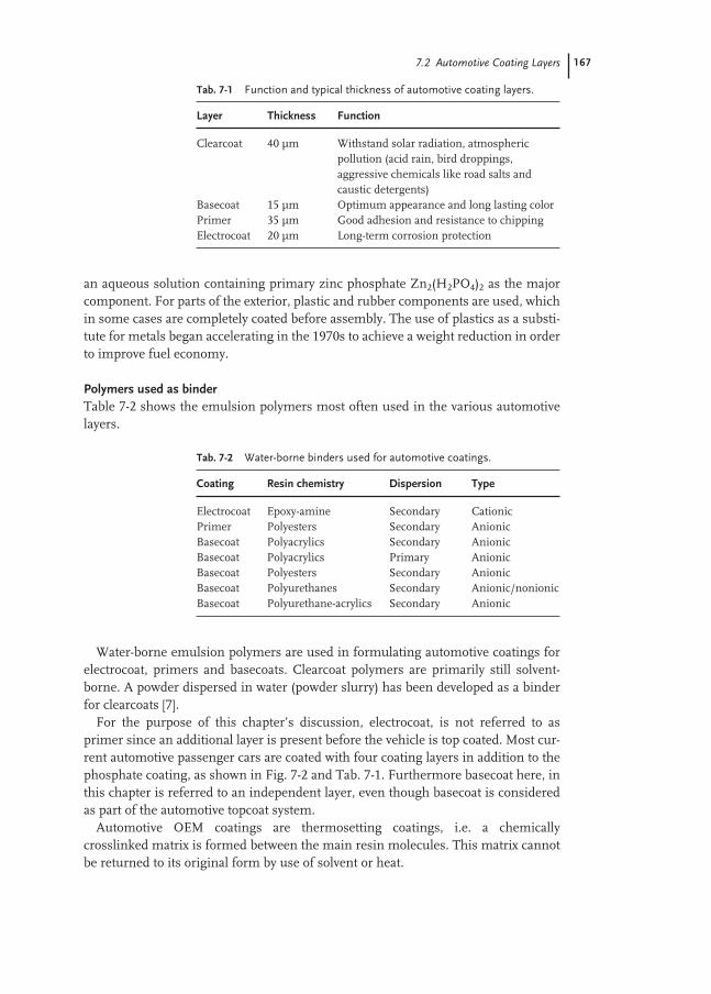
7.2 Automotive Coating Layers 167
an aqueous solution containing primary zinc phosphate Zn2(H2PO4)2 as the majorcomponent. For parts of the exterior, plastic and rubber components are used, whichin some cases are completely coated before assembly. The use of plastics as a substi-tute for metals began accelerating in the 1970s to achieve a weight reduction in orderto improve fuel economy.
Polymers used as binderTable 7-2 shows the emulsion polymers most often used in the various automotivelayers.
Water-borne emulsion polymers are used in formulating automotive coatings forelectrocoat, primers and basecoats. Clearcoat polymers are primarily still solvent-borne. A powder dispersed in water (powder slurry) has been developed as a binderfor clearcoats [7].
For the purpose of this chapter’s discussion, electrocoat, is not referred to asprimer since an additional layer is present before the vehicle is top coated. Most cur-rent automotive passenger cars are coated with four coating layers in addition to thephosphate coating, as shown in Fig. 7-2 and Tab. 7-1. Furthermore basecoat here, inthis chapter is referred to an independent layer, even though basecoat is consideredas part of the automotive topcoat system.
Automotive OEM coatings are thermosetting coatings, i.e. a chemicallycrosslinked matrix is formed between the main resin molecules. This matrix cannotbe returned to its original form by use of solvent or heat.
Tab. 7-1 Function and typical thickness of automotive coating layers.
Layer Thickness Function
Clearcoat 40 µm Withstand solar radiation, atmospheric pollution (acid rain, bird droppings, aggressive chemicals like road salts and caustic detergents)
Basecoat 15 µm Optimum appearance and long lasting colorPrimer 35 µm Good adhesion and resistance to chippingElectrocoat 20 µm Long-term corrosion protection
Tab. 7-2 Water-borne binders used for automotive coatings.
Coating Resin chemistry Dispersion Type
Electrocoat Epoxy-amine Secondary CationicPrimer Polyesters Secondary AnionicBasecoat Polyacrylics Secondary AnionicBasecoat Polyacrylics Primary AnionicBasecoat Polyesters Secondary AnionicBasecoat Polyurethanes Secondary Anionic/nonionicBasecoat Polyurethane-acrylics Secondary Anionic

168 7 Applications for Automotive Coatings
Aqueous polymer dispersions used in automotive water-borne coatings are classi-fied as:– primary dispersions: polymerization is carried out in the presence of water by emul-
sion or mini emulsion polymerization.– secondary dispersions: the polymer is synthesized in an organic solvent and later dis-
persed in water.Based on the nature of the solubilizing group, the polymer is classified as anionic,
cationic or nonionic. The higher the concentration of the polar groups, the greater isthe solubility of the polymer. Incorporation of functional groups in the polymerskeleton is necessary for stabilization in aqueous phase [12].
Formulation ingredientsThe amounts of main ingredients present in a water-borne automotive coating for-mulation are shown in Tab. 7-3; the functions of these ingredients are summarizedin Tab. 7-4.
Standard test methodsThe standard test methods for automotive water-borne coatings are summarized inTab. 7-5.
Tab. 7-3 Main ingredients (%) of for automotive coatings, RCA: rheology control agent.
E-coat Primer Base coatMetallic Solid color
Solids (resins, crosslinker(s), pigments) 17–24 35–45 23–25 25–30Solvents 2– 3 5– 7 10–15 10–15Additives (RCA, defoamer, wetting agents) 1– 2 2– 3 2– 3 2– 3Water 71–80 45–58 57–65 52–63
Tab. 7-4 Function of ingredients in an automotive coating formulation.
Ingredient Function
Aqueous polymer dispersion Film formation, mechanical propertiesCrosslinker Reacts with functional groups on main resin to form
crosslinked matrixPigment dispersion Provides color, hidingFlake pigments Provides appearance effectSolvents Reduces viscosity, controls rate of drying and film formationUV absorber Inhibits degradation of film by sunlightCatalyst Drives crosslinking reactionSecondary resins Pigment dispersion, adhesion promotionAntifoamer/defoamer Decrease foaming tendenciesRheology control agents (RCA) Control leveling, sag, aligns aluminum flakes
(metallic basecoats)Other additives Improve substrate wetting, flow, pop tolerance, etc.

7.2 Automotive Coating Layers 169
The test methods for automotive layers are designed to stimulate conditions likelyto occur in the field and are of two types – appearance and performance. Appearanceincludes gloss, distinctness of image, mottle, orange peel. Performance propertiesinclude physical properties of hardness, flexibility, impact resistance, adhesion,stone-chip resistance, cold crack resistance i.e. stability to extremes of temperatureand humidity, curing efficiency.
Polymer dispersions are applied as coating binder mainly in three of the fourlayers: electrocoat, primer and basecoat. These layers are now described in moredetail.
Tab. 7-5 Test methods for automotive coatings.
Test Method Description
E-coat Stomer ASTM D562 ViscosityBasecoat, primer ICI cone/plate ASTM D4287 ViscosityBasecoat, primer Brookfield ASTM D2196 ViscosityBasecoat, primer Ford viscosity ASTM D1200 ViscosityBasecoat, primer Dip type ASTM 4212 ViscosityE-coat, primer, Film build ASTM D1186, Thicknessbasecoat ISO 7253,
ISO 4623E-coat Salt spray resistance ASTM B117, Corrosion, J2334 preferred to
SAE J2334, B117DIN 53167
E-coat, primer Gravelometer J 400 Chip resistance testing, testing coating flexibility, adhesion and overall resistance to chipping damage by stones
E-coat Hardness (pencil) ASTM D3363 HardnessE-coat Impact (Gardner) ASTM D5420 HardnessE-coat, primer, Humidity ASTM D1735, Adhesion and appearance. basecoat ASTM D2247, Condensing humidity (D2247)
ASTM D4585, and water soak (D1735)DIN 53209
Topcoat, primer UV SAE J2020 Appearance (gloss, cracking ,chalking) Weathering test
Topcoat, primer Xenon lamp SAE J1960 Accelerated test to check for gloss loss
Topcoat, primer Sunshine/ ASTM G 152 Accelerated test to check carbon arc for gloss loss
Topcoat, primer Tape test ASTM D3359 AdhesionTopcoat, primer Exposure SAE J 951 Durability, Florida exposure Topcoat, primer Exposure SAE J 1976 Outdoor weathering of exterior
materials
The J tests were developed by the Society of Automotive engineers, USA (www.SAE.org)
170 7 Applications for Automotive Coatings
7.2.2
Electrocoat
Electrocoat or e-coat or Elpo is the first pigmented coating layer, which is appliedover the phosphate coating of the fabricated car steel body. It serves as a bridge between the metal and the overlaying coating layers. This coating layer is applied in a dip application by cathodic electrodeposition to the steel automobile body. Dipapplication has the advantage to fill the smallest recessed areas of the automobilebody. This complete coverage ensures excellent corrosion protection to the automo-bile.
Cationic electrocoat applied by dipping process is used worldwide for coating au-tobodies and its adoption in 1970s and 1980s led to major improvement in the corro-sion resistance of cars. Until mid 1970, electrocoat was of the anodic type [13–15]. In1976, PPG introduced the first cathodic primer, and this technology, with continu-ous improvement, has become the standard of the automotive industry worldwide.Combined with the more recent introduction of galvanized sheet metal, car manu-facturers are now able to offer ten years warranties against corrosion.
RequirementsCurrent systems are characterized by excellent corrosion protection, good throwingpower and good filling properties at film thickness of ca. 20 µm.
Polymers usedThe resins used in electrocoat, must have excellent hydrolytic stability and resistanceto salt accelerated corrosion and the chemical composition of the resin also allowsfor excellent adhesion of the next coating layer. Most current cathodic systems arebased on modified epoxy resins containing amino groups. These are dispersed inwater by neutralizing the amino groups with organic acids such as formic, acetic orlactic acid. Bisphenol A epoxy resins are reacted with polyamines to yield a resin withamine and hydroxyl groups. The resulting polymer is reacted with a polyisocyanate,which is partially blocked with an alcohol (e.g. 2-ethylhexyl alcohol). Salts are formedwith the amine groups with a low molecular weight carboxylic acid. The epoxy back-bone is made flexible by various ways by incorporation of polyester and polyetherdiols [16], acrylic grafts [17]; low-Tg aliphatic epoxies [18]; fatty acids [19] and fattymonoepoxies [20].
The resins are crosslinked by blocked isocyanates, Mannich reactions or re-esteri-fication. Blocked isocyanates which are used as crosslinking agent are stable in theslightly acidic water system, whereas melamine formaldehyde resins are not. Duringbaking, the blocked isocyanate reacts with a hydroxyl group to form a urethanecrosslink. Amine-substituted resin binders provide greater corrosion protection forsteel, perhaps owing to strong interaction between the amine groups and the sub-strate surface that increases wet adhesion, which is the most critical factor for corro-sion protection.
Cationic polyurethane dispersions are obtained by incorporating tertiary aminefunctionality into the backbone, either by introducing tertiary amine groups in the

7.2 Automotive Coating Layers 171
diol, instead of a carboxylic group, followed by quaternization with an alkylatingagent or protonation with a suitable acid [21].
Other coating systems contain cationically modified copolymers obtained by poly-merization of acrylic monomers in presence of unsaturated polyurethane macro-monomer [22], and water-dilutable dispersions of cationically modified and urethanemodified methacrylic copolymers obtained by solution polymerization [23].
CompositionMost of the commercial cathodic electrocoat formulas are two-pack formulasconsisting of a pigment dispersion intermediate and the principal resin compo-nents [24].
Pigment dispersion:Aqueous dispersion resin (epoxy amine isocyanate adduct) 10–15 %Extenders 20–30 %Anticorrosive pigments 3–7 %Organometallic oxides 1–2 %Deionized water 65–46 %
Principal resin component:Epoxy amine adduct 20–25 %Crosslinker 10–12 %Organic acid 0.5–1.0 %Organic solvent 1–3 %Deionized water 68–69 %
Pigments commonly used are titanium dioxide and extender pigments. Speciallead-containing pigments e.g. silicates are used as anticorrosive agents. Lead also cat-alyzes the curing reaction, however the trend nowadays is eliminate lead from elec-trocoat. Solvent content is low (typically less than 2 % based on total volume). Thesolids content is ca. 20 %.
The application technique allows coating of complicated shapes and even internalareas. A coating of uniform thickness is obtained after baking at 150–180 °C for ca.20 min.
ApplicationThe car body is coated on a production line by immersing the body in a tank con-taining the aqueous primer dispersion and subjecting it to a direct current charge.The applied voltage causes the dispersed particles and pigments to migrate to the carbody. As they are deposited, the consequent transfer of electrons provides an electri-cally neutral film deposit. During the process electroendoosmosis occurs, squeezingthe water out of the deposited coating and leaving it in a firm state. With this process,improved uniform coverage is achieved in recessed areas and on sharp edges as wellas on flat surfaces. The body is baked to coalesce and cure the primer film with muchless sagging occurring.

172 7 Applications for Automotive Coatings
Electrocoat bath:Coatings stable at a pH a little below 7 are preferred.Viscosity: 20–50 mPa s at 25 °CBath solids: 15–25 % (1 h at 110 °C)Water: 64 % Deionized waterSolvents: 1–4 % Organic solventBath pH: 5.0–6.0Bath conductivity (20 °C): 0.8–1.5 mS cm–1
Cure schedule at metal temperature: 165–170 °C for 20 min
7.2.3
Primer
Primer or primer surfacer is spray applied over the electrocoat before applying thebasecoat. The main function is to minimize surface roughness and improve adhe-sion of the basecoat. The uniform thickness provided by the e-coat, makes it smoothand glossy which makes the adhesion to basecoat very difficult. The primer also pro-tects the light sensitive cathodic electrodeposition layer from exposure to light.
Historically the basic function for spray primers has been corrosion resistance andpreparation of a surface to receive a top coat. With the advent of electrocoat in the au-tomotive industry corrosion resistance has become less of a issue for spray primers.The corrosion function of spray primers has centered around protecting againstsanding cut throughs (sanding to bare metal) on the electrocoat primer. Presentlythe main purpose of spray primer is the preparation of a surface to receive a top coat(basecoat/clearcoat). Other properties that are presently of great concern for sprayprimers are yellowing, adhesion, chip resistance, sandability, leveling, UV durabilityand smoothness of the coating with respect to the surrounding coatings (electrocoatand topcoat).
A current trend is to use color key primers; the colors are picked for use under agroup of top coats with related colors. A chip-resistant primer called anti-chip is fre-quently applied over the electrocoat on the lower parts of the car body. It is designedto be especially resistant to impact by stones thrown up from a road against the carbody.
RequirementsThe primer must have good chip resistance and exterior durability. Weakness in thelayer will lead to UV radiation degradation causing loss of adhesion of primer tobasecoat/clearcoat and ultimately delamination.
Polymers usedThe development of chip resistant water-borne primer-surfacers has benefited fromthe use of predominantly water-borne polyester and polyester-polyurethane resins.Polyesters which are dissolved or dispersed in water by neutralizing acid groups with amines are crosslinked with a suitable melamine resin. Aqueous polyurethaneor acrylic modified polyurethane systems are also slowly entering the primer market.
7.2 Automotive Coating Layers 173
Water-borne polyesters used for automotive coatings have both hydroxyl and car-boxylic groups as terminal groups. Usual acid numbers are in the range of 35–60 mgKOH g–1 resin, to give amine salt solutions in solvent that can be diluted with waterto give reasonable stable dispersions of aggregates of resin molecules swollen withwater and solvent. To give acid functionality, 2,2,-bis(hydroxymethyl)propionic acidis used as one of the diol components. Hydrolytic stability is also affected by thechoice of the polyol. In addition to the steric effect, it has been shown that polyolswith low water solubility give polyesters that are more stable against hydrolysisunder basic conditions than those with higher water solubility, presumably becausethe polymers are more hydrophobic.
Since many of the polymers are hydroxyl functional, they are cured with variousmelamines and blocked isocyanates. The polymers are mainly stabilized in the waterphase by neutralization of anionic groups with amines which are volatile (di-methylethanolamine, 2-amino-2-methyl-1-propanol).
To avoid emulsifiers, the polyesters are copolymerized with hydrophilic mono-mers. In the case of linear high molecular weight polyesters, often sodium 5-sul-foisophthalic acid, polyethylene glycol are copolymerized. However, the copolymer-ization increases the melt viscosity and decreases water resistance and adhesion. Wa-ter-borne polyesters which are of the acrylics-grafted type form stable aqueous dis-persion. They consist of “core-shell” particles with a core of high molecular weightpolyester. Small particle diameters were obtained by use of polyesters having thelargest amount of unsaturated bonds unless gelation occurs [24–30]. Thermosettingwater based polyester resin coating composition prepared from polyalkadienediolmay be directly applied to wet electrodeposited coating [31].
Composition of primerPrimers are highly pigmented systems, containing titanium dioxide in combinationwith extender pigments such as silicates or barium sulfate, carefully selected to im-prove the paint attributes (leveling, sanding, humidity resistance). UV absorbers andHALS stabilizers can be added to improve UV resistance. The pH of the system ismaintained between 7 and 8.
Application and testingPrimer coating are spray applied onto the electrocoated substrate. Typical wet phasetesting includes seed check, gloss, weight per gallon, viscosity, appearance, humiditysensitivity, settling , impact resistance, topcoat adhesion, solvent resistance, filter-ability and sand scratch telegraph. For the anti-chip-appearance, weight per gallon,viscosity, solids, sag and solvent pop and gravelometer-chip resistance test are used.
7.2.4
Basecoat
Basecoat is the layer which contains the color pigments. This layer is covered by thetransparent coating (clearcoat).
174 7 Applications for Automotive Coatings
Basecoats – along with the clearcoat also called the topcoat system – form protec-tive layers over the car body surface and are very important as decoration. They havethe characteristics of:– full and deep gloss– highly brilliant solid or metallic color effects– long-lasting resistance against weather and chemical influences– easy to repair and polish
In terms of appearance, a significant trend in automotive original equipment fin-ishes has been influenced the dramatic growth in the use of basecoat-clearcoat fin-ishes to replace single-stage pigmented topcoats. Basecoat-clearcoat finishes providea “wet” appearance, previously associated with European vehicles, in that the appear-ance of the basecoat is enhanced by the transparent clearcoat. Because of thesmoothness of the surface and clarity of the film of the clearcoats, the gloss and dis-tinctness of the image of these multi-stage finishes has been widely accepted as thestandard of appearance in both the automotive original equipment and refinish coat-ings markets.
The basecoat/clearcoat system consists of a colored layer (basecoat) which isovercoated after a brief flash off time with a protective layer of clearcoat. Both layersare cured together at about 120–140 °C. The basecoat contains pigments which pro-vide solid (straight) shades or metallic finishes. In order to reduce the emissions ofVOC, water-borne basecoats have been developed, which may contain only up to20 % co-solvents.
Composition of basecoatThe pH of the system is maintained between 7.0 and 8.0. Approximately 10–15 % byweight is comprised of solvents. The trend nowadays is to go with HAPS (HazardousAir PollutantS) compliant solvents like monoethers of propylene glycol. Solventshelp in achieving good flow and leveling of the coating after it is sprayed. They alsohelp in proper alignment of the metal flakes of a metallic coating. A UV absorber inthe top coat that strongly absorbs UV in the wavelength range of 290–380 nm alsohelps to protect the primer from degradation. HALS stabilizers are added to improveUV resistance. Water-borne basecoats contain crosslinker building a polymer net-work and ensuring film stability and durability. Water-borne basecoats also containrheology modifiers e.g. polyurethane thickeners [32], polyacrylic acids [33] and pig-ment like additives (metasilicates, colloidal silicon dioxide).
Metallic pigments are frequently incorporated into the basecoat to provide the ap-pearance phenomenon known as the geometric metamerism or “color-travel”. Coat-ings with geometric metamerism display different hue and brightness when viewedat different angles. This effect is used by automotive stylists who specify metallicbasecoat–clearcoat finishes to draw viewers eye the subtle contrast in hue and bright-ness found in styling lines and curvatures in the vehicle.
Even though, water-borne coatings have been the most popular approach to VOCreduction and there has been a substantial reduction of solvents on going fromsolvent-borne systems to water-borne systems, the trend now is to eliminate solvents
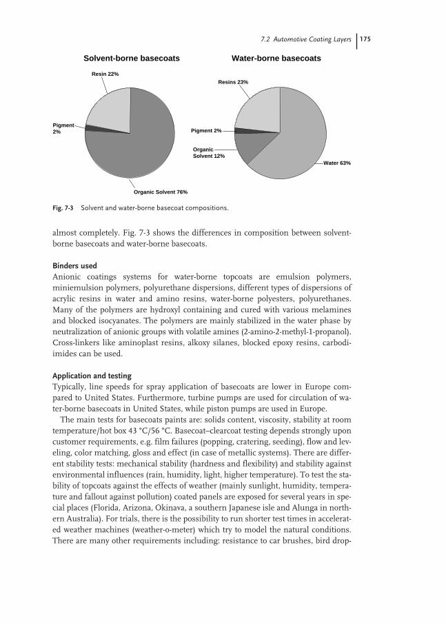
7.2 Automotive Coating Layers 175
almost completely. Fig. 7-3 shows the differences in composition between solvent-borne basecoats and water-borne basecoats.
Binders usedAnionic coatings systems for water-borne topcoats are emulsion polymers,miniemulsion polymers, polyurethane dispersions, different types of dispersions ofacrylic resins in water and amino resins, water-borne polyesters, polyurethanes.Many of the polymers are hydroxyl containing and cured with various melaminesand blocked isocyanates. The polymers are mainly stabilized in the water phase byneutralization of anionic groups with volatile amines (2-amino-2-methyl-1-propanol).Cross-linkers like aminoplast resins, alkoxy silanes, blocked epoxy resins, carbodi-imides can be used.
Application and testingTypically, line speeds for spray application of basecoats are lower in Europe com-pared to United States. Furthermore, turbine pumps are used for circulation of wa-ter-borne basecoats in United States, while piston pumps are used in Europe.
The main tests for basecoats paints are: solids content, viscosity, stability at roomtemperature/hot box 43 °C/56 °C. Basecoat–clearcoat testing depends strongly uponcustomer requirements, e.g. film failures (popping, cratering, seeding), flow and lev-eling, color matching, gloss and effect (in case of metallic systems). There are differ-ent stability tests: mechanical stability (hardness and flexibility) and stability againstenvironmental influences (rain, humidity, light, higher temperature). To test the sta-bility of topcoats against the effects of weather (mainly sunlight, humidity, tempera-ture and fallout against pollution) coated panels are exposed for several years in spe-cial places (Florida, Arizona, Okinava, a southern Japanese isle and Alunga in north-ern Australia). For trials, there is the possibility to run shorter test times in accelerat-ed weather machines (weather-o-meter) which try to model the natural conditions.There are many other requirements including: resistance to car brushes, bird drop-
Fig. 7-3 Solvent and water-borne basecoat compositions.
Pigment 2%
OrganicSolvent 12%
Resins 23%
Water 63%
Resin 22%
Organic Solvent 76%
Pigment2%
Water-borne basecoats Solvent-borne basecoats

176 7 Applications for Automotive Coatings
pings, acid rain, sudden thunder showers on a car that has been sitting in the hotsun, the impact of pieces of gravel striking the car, gasoline spillage and so on.
7.3
Properties of Water-borne Binders used for Automotive Coatings
7.3.1
Emulsion Polymers
Emulsion polymers are binders of choice for automotive water-borne basecoats ap-plications, because of their low cost and processing requirements. A particularlyvaluable element of acrylic emulsion polymer chemistry is the ability to incorporatea broad range of functional chemical groups into the polymer chain via ester, amidecarbamate, derivatives of acrylic or methacrylic acid. These functional groups canprovide sites for crosslinking, adhesion, compatibility with other polymers, post-polymerization reactions, biochemical activity, etc. Acrylic latexes are increasinglybecoming popular for basecoat automotive applications, because of their resistanceto photodegradation and low cost, in addition to their well-known features includingsafe handling, low toxicity, low odor, and easy clean-up. A number of patents exist inthe literature, wherein core shell polymers have been suggested to be used for water-borne basecoats. To achieve good flow properties, a low minimum film-formingtemperature, good stability to agitation and good adhesion to other coating layers,multiphase emulsion polymers are used, where the latex particles are small in size,the core material is hard and the shell is soft and the latter is made of strongly hy-drophobic monomers and a relatively large proportion of monomers carrying car-boxyl groups [34–36].Acrylic core-shell polymers have been used as principal polymers for aqueous metal-lic basecoat paints [37–40]. The anionic shell allows pseudoplastic flow behaviorwhich ensures parallel orientation of the aluminium pigments in the wet paint film.This orientation and the low solids content are responsible for the metallic gloss andhigh color flop (change in color observed on varying the viewing angle) of the base-coats.For thermoset automotive coatings cross-linkable polymer dispersions areused [41–47]. Compositions containing methylol(meth)acrylamide can be used forvery low VOC water-borne coatings. Relatively low-Tg polymers that coalesce wellwithout coalescing solvents are applied and subsequent crosslinking will give the re-quired film properties. Water-soluble or a water-dispersible alkylated melamineformaldehyde crosslinking agent or a polymeric partially methylated melamineformaldehyde resin having a degree of polymerization of approximately 1–3 are usedfrequently. Such compositions have been used for automotive quality clear coatand/or pigmented color coat for automobiles and for an automotive quality primercomposition [48]. Functionalized latexes in baked coatings can be crosslinked withaminoplast resins, alkoxy silanes, blocked isocyanates, epoxy resins and many othercross-linkers.

7.3 Properties of Water-borne Binders used for Automotive Coatings 177
To improve the water resistance, branched vinyl esters with long hydrophobicchains can be used [49].
Emulsion polymerization is carried out as a semi-continuous batch process [50].The polymer particle size is between 50 and 500 nm.
7.3.2
Microgels
Microgels are used as rheology control agents (RCA) for solvent-borne basecoats andclearcoats. They are crosslinked microparticles made by emulsion polymerizationusing monomers like ethylene glycol dimethacrylate, allyl methacrylate or divinyl-benzene. They are insoluble in the aqueous medium and are stable towards grossflocculation. The chemical composition and degree of crosslinking of the microparti-cle may be such that it has a Tg below room temperature in which case the mi-croparticles will be rubbery in nature, alternatively, it may be such that the Tg isabove room temperature, that is to say the particles will be hard and glassy. The poly-mer micro-particles can be dispersed in the basecoat composition in a state in which,even at low solids contents, the dispersion contains a few if any multi-particle aggre-gates. The presence of the crosslinked polymer microparticles in the basecoat com-position, confers upon the film derived from the latter, the desired ability to with-stand subsequent application of the topcoat composition without disturbance of thefilm or of the pigmentation, in particular metallic pigmentation, which it containsand without which, therefore a successful basecoat/clearcoat system cannot beachieved. Microgel dispersions having a pseudoplastic or thixotropic character havebeen used for formulating metallic pigments in the basecoat composition. This givesthe advantage of the flip tone effect as well as the gloss to produce the ever popularmetallic finishes for the automotive industry [51].
7.3.3
Miniemulsions
Significant advances have been made in recent years in applying miniemulsions formaking water-borne polymers for the coating industry. Since the introduction ofminiemulsion polymerization in the early 1970s [52] many investigators have stud-ied the subject and have used many different methods to prepare miniemul-sions [53–57]. Miniemulsions are routinely prepared using some kind of high sheardevice, in most cases this being an ultrasonifier or a microfluidizer [58].
Shork et al. have shown that incorporation of polyester into each acrylic latex parti-cle, prepared via miniemulsion polymerization, leads to an effective in situ graftingof the acrylic and polyester systems [59]. The hydrophobic nature of the polyesterresin makes it impossible to be accommodated by traditional emulsion polymeriza-tion due to mass-transfer limitations in crossing the aqueous phase to micellar nu-cleation sites. Thus, stable water-based latex coatings can be prepared that also havethe ability to cure (by crosslinking).The above hybrid miniemulsion polymerizationwas successfully used to incorporate an oil modified polyurethane in the acrylic
178 7 Applications for Automotive Coatings
droplets to give stable miniemulsions which were polymerized to give hybrid latex-es [60, 61]. The hybrid polyurethane modified miniemulsion latexes have been suc-cessfully used in formulating coatings for basecoats [62–64].
Additionally, miniemulsions made using a mixture of polyurethane and acrylicmonomers were used to make latexes using a semi-continuous feed. This techniquewas successfully used to core-shell polymers for use in making water-bornebasecoats [64, 65]. Stable aqueous dispersion of polymeric microparticles containingcellulose ester, and an acrylic polymer and a surfactant has been used for coatingcompositions. These coating compositions have good leveling and flow characteris-tics and exhibit good humidity resistance, appearance, adhesion and chip resistancewhen used in a “low bake repair” process as well as a good automotive quality fin-ish [66]. These dispersions of microparticles are produced by high stress dispersionfollowed by polymerization of the vinyl monomers in the presence of cellulose esterwithin the micro-particles.
7.3.4
Selection of Monomers, Initiators, and Surfactants
Glass transition temperature is usually the first design property considered for theapplication. Hydrophilicity, hydrophobicity, acid-base properties, crosslinking abilityare other properties [67, 68]. Acrylic acid (AA) or the somewhat less water-solublemethacrylic aid (MAA) are used in the order of 1–2 % (w/w) of the monomer charge.The effects of acid monomers on stability and viscosity are maximized when they areincorporated in the last part of the monomer feed and the polymerization medium isacidic. Sometimes di- or tri-functional cross-linking monomers are included. To im-prove acid rain etch resistance, carbamate functional monomers are included,wherein the carbamate groups crosslink with melamine, used for clearcoats. Theaminoplast cured coating system combines acid resistance with excellent coatingproperties providing protection against etching by acid rain [69].
The most common initiators are peroxydisulfate salts, especially ammonium per-oxydisulfate. Thermal initiation is preferred to redox initiation. Whitening of filmsmay occur sometimes due to the hydrophilicity of the salts like ferrous thiosulfate. Awater soluble azo initiator 4,4′-azo-bis(cyanovaleric acid) has also been used for mak-ing acrylic latexes [70].
Chain transfer agents are sometimes added to control the molecular weights andthe distribution. Latexes and coatings are stabilized by biocides or water-miscible sol-vents to prevent microbiological contamination and deterioration [71]. Choice of sur-factants are critical for automotive paint application due to their foaming tendency,ability to impart water sensitivity to paint films and change gloss characteristics. Typ-ically a low particle size in the range of 50–300 nm is preferred, so in general anion-ic surfactants are used at levels of 0.5–2 % (w/w) based on polymer. Nonionic sur-factants may be added in stabilizing the latex against coagulation during freeze-thawcycling making it less sensitive to coagulation by salts, less sensitive to changes inpH. Choice of surfactant can also affect film formation temperature, since somenonionic surfactants plasticize the latex polymer, leading to lower Tg and hence, a
7.3 Properties of Water-borne Binders used for Automotive Coatings 179
lower temperature for coalescence. For example, nonylphenylethoxylate nonionicsurfactants with less than nine ethoxy units reduce film formation temperature ascompared to 20 to 40 ethoxylate units, but the higher ethoxylated surfactants aremore effective latex stabilizers [72].
7.3.5
Secondary Acrylic Dispersions
Automotive coatings containing acrylic resins as binders are well known. Organicsolvents used are generally alcohols, glycol ethers and other oxygen-containingsolvents that are soluble or miscible with water. Acrylic resins made in solvents (e.g.1-(n-propoxy)-2-propanol, 2-butoxyethanol, butyl alcohols) are polymerized by free-radical mechanisms. Typical monomers used are MMA/BA/BMA. Azo initiators aretypically used. Hydroxy monomers like HEMA, HEA are used, while acrylic acidmonomers are used to impart water solubility. After polymerization the carboxylicacid groups are neutralized. Typically, these resins have acid numbers of 40–60 (acidnumber is determined by titration and is defined as mg of KOH required to neutral-ize 1 g of resin solids, equivalent weight equals 56 100/acid number). In the low-mo-lecular-mass range (<6000 g mol–1), the Tg depends on the molecular mass. Subse-quent cross-linking leads to an increase of Tg which is dependant on the cross-link-ing density.
The choice of amine is crucial. 2-(dimethylamino)ethanol is widely used [73]. Ther-moplastic latexes are of higher Tg (upwards of 60 °C) are used for higher toughness,mar and chemical resistance, since heat is available for film formation. The hydrox-ylic monomers can be incorporated for cure with melamine and isocyanate resins,the carboxyl monomers can provide cure with epoxies, aziridines and carbodiimides.
7.3.6
Secondary Polyurethane Dispersions
Another important class of materials used for OEM coatings are aqueouspolyurethanes due to their versatility in their properties [74–80]. Since the introduc-tion of polyurethane dispersions in 1960s, they have enjoyed considerable interestand commercial acceptance. Polyurethane dispersions can be classified into threemain groups:– non-ionic type;– ionic type; and– dispersions containing both the non-ionic and the ionic groups.
Anionic PU dispersionsIn the first step of the synthesis, a conventional polyether- or polyester-based iso-cyanate-terminated prepolymer is obtained by condensation polymerization of a dioland a diol containing a carboxyl function, preferably reacting the hydroxyl groups ofdimethylol propionic acid with isocyanate groups. In the next step, the carboxylgroups are neutralized with an amine which is subsequently dispersed in water and
180 7 Applications for Automotive Coatings
chain extended in order to obtain high-molecular-weight materials by reacting with adiamine in further steps. Aliphatic isocyanates are preferred, because beside confer-ring good durability, they show lower reactivity with water and carboxylic groups.Further aliphatic isocyanates favor very rapid reaction with diamines in the chain ex-tension step. As neutralizing bases, tertiary amines are preferred compared to otheramines to prevent unwanted side reactions with isocyanates. A number of diols, iso-cyanates and amine raw materials can be used to adjust the mechanical properties,glass transition temperature and durability.
Non-ionic DispersionsIn the non-ionic types, the hydrophilic centers comprise of polyether chain seg-ments [75, 81]. The different morphology exhibited by aqueous polyurethanes andacrylics explains why the minimum film forming temperatures of polyurethane dis-persions (PUD) are lower than that of acrylics with equal hardness [82]. Polyurethaneparticles can exhibit core-shell morphology with the shell having higher molecularweight and higher urea functionality than the core. This effect was found to be quitepronounced with isophorone diisocyanate-based polyurethane dispersions [83]. Atwo coat one bake coating process which does not give environmental problems hasbeen developed using aqueous PUD [84, 85].
Water-borne basecoats containing polyurethanes have been produced with a for-mulation containing less than three pounds per gallon and lower temperatures thansolvent-borne systems [86]. Rapid-drying polyurethanes have been used for industri-al finishing and automotive refinish with a well-balanced range of properties at lowVOC level. High-performance OEM-clearcoats have been produced with good chem-ical resistance with excellent mar resistance. Some limitations of using anionic wa-ter-borne polyurethanes are, volatile amines used to salt these carboxylic acid-func-tional resins, which leaves during baking, thereby hindering the cure of the strongacid-catalyzed acrylic-melamine clearcoats, resulting in wrinkled finish and loss ofDOI (Distinctness of image), and the limited rheological stability with metallic for-mulations which contain certain rheology control agents. In certain formulations,anionic PU resins have generally not given satisfactory application properties andpaint stability. In response to these limitations, nonionic polyurethane dispersionswere developed [87, 88].
Hybrid systemsThe blending of resins is a simple and useful technique for improving paint proper-ties. While water-borne acrylic resins and polyurethanes have been widely used aspolymers for automotive coatings, both water-borne resins are inferior to correspon-ding solvent based counterparts because of hydrophilic functional groups or surfac-tants which are introduced to impart dispersion stability to these resins. Table 7-6shows some of the advantages and disadvantages of polyurethane and acrylic resins.
The most widely utilized technique for making hybrids is to free radically poly-merize a combination of monomers in the presence of a pre-formed polymer whichmay or may not be intrinsically dispersible. If the preformed polymer is water dis-persible, it can be used directly as a seed for subsequent free radical polymerization.

7.4 Rheology 181
Urethane acrylic aqueous dispersions prepared by an acrylic polymerization in thepresence of an aqueous polyurethane can possess a range of advantages over the cor-responding blends, e.g. reduced water sensitivity, ability to prepare in the cosolventform. Since polyurethanes are generally more hydrophilic than the acrylic copoly-mer, the polyurethane concentrates at the particle surface. In a well designed system,the particles coalesce on film formation to give a film with a continuous poly-urethane phase. “Hybrid” acrylic-urethane latexes have been made by simultaneouspolymerization of acrylic monomers and chain extension of urethane prepolymersgiving structures similar to interpenetrating network polymers, with mechanicalproperties exceeding those, if blended [89].
Combination of special emulsions, microgels and water-soluble resins have yield-ed excellent aqueous binders for various coatings [25].
7.4
Rheology
A major concern in developing water-borne automotive coatings is to achieve a dis-tinct rheology profile providing good sprayability, sag resistance and leveling proper-ties, simultaneously. In low solids solvent-borne systems, controlling the rate of sol-vent loss controls viscosity and sagging and metal flake orientation. In water-bornesystems rheology control agents (RCA) are added to control sag and flake orienta-tion.
The viscosity of the paint must be very low at the spray gun in order to ensure agood and uniform atomization. After the paint meets the car body, however its vis-cosity needs to be very high so as to prevent sagging on vertical surfaces and cloud-ing. The flow behavior of the aqueous basecoat therefore has to be adjusted by in-cluding a rheology additive, the thickener, in the formulation. The paint must have agood intrinsic viscosity, i.e. the viscosity must depend on the shear rate. With a highshear force, such as is present at the nozzle during the spraying process, the viscosi-ty needs to be very low. If the paint then meets the car body, it is virtually unaffected
Tab. 7-6 Advantages and disadvantages of polyurethane andacrylic resins.
Advantages Disadvantages
Acrylics Hardness ToughnessWeatherability Mar resistanceChemical resistance ElongationGlossAffinity for pigmentsCost
Polyurethanes Mar resistance CostElongationSoftness and adhesion
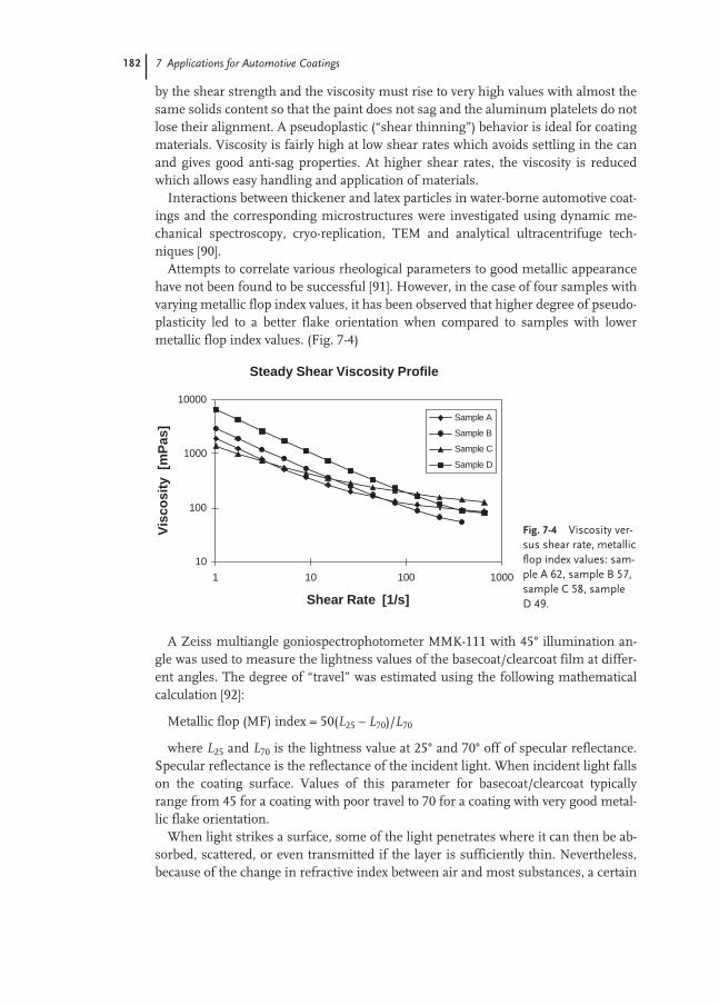
182 7 Applications for Automotive Coatings
by the shear strength and the viscosity must rise to very high values with almost thesame solids content so that the paint does not sag and the aluminum platelets do notlose their alignment. A pseudoplastic (“shear thinning”) behavior is ideal for coatingmaterials. Viscosity is fairly high at low shear rates which avoids settling in the canand gives good anti-sag properties. At higher shear rates, the viscosity is reducedwhich allows easy handling and application of materials.
Interactions between thickener and latex particles in water-borne automotive coat-ings and the corresponding microstructures were investigated using dynamic me-chanical spectroscopy, cryo-replication, TEM and analytical ultracentrifuge tech-niques [90].
Attempts to correlate various rheological parameters to good metallic appearancehave not been found to be successful [91]. However, in the case of four samples withvarying metallic flop index values, it has been observed that higher degree of pseudo-plasticity led to a better flake orientation when compared to samples with lowermetallic flop index values. (Fig. 7-4)
A Zeiss multiangle goniospectrophotometer MMK-111 with 45° illumination an-gle was used to measure the lightness values of the basecoat/clearcoat film at differ-ent angles. The degree of “travel” was estimated using the following mathematicalcalculation [92]:
Metallic flop (MF) index = 50(L25 – L70)/L70
where L25 and L70 is the lightness value at 25° and 70° off of specular reflectance.Specular reflectance is the reflectance of the incident light. When incident light fallson the coating surface. Values of this parameter for basecoat/clearcoat typicallyrange from 45 for a coating with poor travel to 70 for a coating with very good metal-lic flake orientation.
When light strikes a surface, some of the light penetrates where it can then be ab-sorbed, scattered, or even transmitted if the layer is sufficiently thin. Nevertheless,because of the change in refractive index between air and most substances, a certain
Fig. 7-4 Viscosity ver-sus shear rate, metallicflop index values: sam-ple A 62, sample B 57,sample C 58, sample D 49.
Steady Shear Viscosity Profile
10
100
1000
10000
1 10 100 1000
Shear Rate [1/s]
Vis
cosi
ty [
mP
as]
Sample A
Sample B
Sample C
Sample D

7.5 Crosslinking 183
proportion of the incident light is reflected directly from the surface. The angulardistribution of this light depends upon the nature of the surface but light that is re-flected at the opposite angle to the incident light is called specular reflectance. Lightthat is reflected by the substance itself is called body reflectance. Instead of examin-ing the energy that passes through the sample, specular reflectance measures the en-ergy that is reflected off the surface of a sample or its refractive index. By examiningthe frequency bands in which the rate of change in the refractive index is high, userscan make assumptions regarding the absorbency of the sample.
Acrylic microgels have been developed that impart thixotropic flow using swollengel particles [52, 93–96]. Thixotropic agents are added to increase the viscosity at lowshear rates to minimize sagging [97, 98]. In the final film, the index of refraction ofthe polymer from the microgel is nearly identical with that of the crosslinked acrylicbinder polymer so that light scattering does not interfere with color flop. The effectof the gel particles depends on the interaction with the low molecular weight resin.The rheological properties of the systems are discussed elsewhere [99].
7.5
Crosslinking
Thermoset coatings (chemically crosslinked film) play a very important role in theautomotive coatings industry. All coating layers uses resins which need to becrosslinked. By crosslinking the resin used in the coating, many properties can begreatly improved, such as hardness, mar resistance and solvent resistance.Crosslinking reactions became important in the 1950s with the introduction ofacrylic resins in the automotive sector. A further impetus was given by increasinglystringent environmental legislation. Lower solvent content and the replacement ofconventional solvent-borne paints by water-based paints meant that the molecularmass of the binders had to be lowered to a range where the required paint properties(film formation, hardness and flexibility) no longer exist. These properties thereforehad to be obtained by increasing the molecular mass by crosslinking after applica-tion. Furthermore, the glass transition temperature and film hardness are increased,the chemical reaction after application also provides advantages of high molecularmass dispersions.
A widely used method of cross-linking paint films consists of reacting of hydroxylcontaining acrylates or carbamate containing acrylates with melamine-formaldehyderesins or urea-formaldehyde resins [100–102]. Crosslinking is carried out atca.130 °C and is effected by acid catalysis (Fig. 7-5). The paints exhibit outstandinggloss and durability [103].
The possibility of making cross-linkable latexes by emulsion polymerization in thepresence of etherified melamine-formaldehyde resins has been demonstrated byJones et al. [104]. Dynamic mechanical measurements showed that films fromslightly or moderately cross-linked particles behave like homogeneous networks inthe linear viscoelastic range [105]. Melamine formaldehyde cross-linkers have been
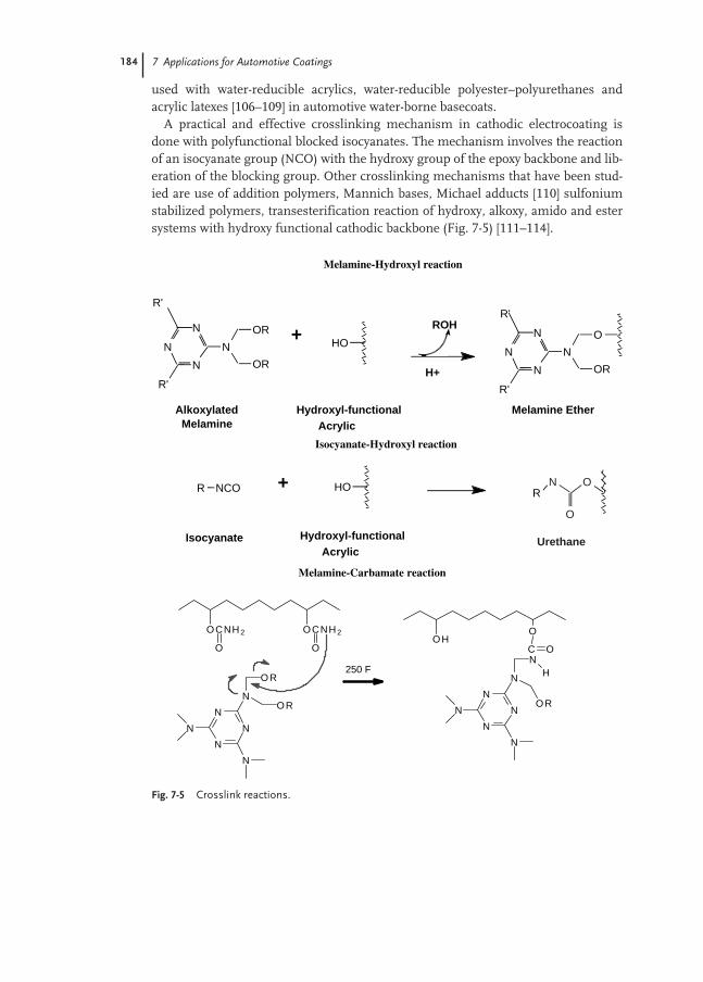
184 7 Applications for Automotive Coatings
used with water-reducible acrylics, water-reducible polyester–polyurethanes andacrylic latexes [106–109] in automotive water-borne basecoats.
A practical and effective crosslinking mechanism in cathodic electrocoating isdone with polyfunctional blocked isocyanates. The mechanism involves the reactionof an isocyanate group (NCO) with the hydroxy group of the epoxy backbone and lib-eration of the blocking group. Other crosslinking mechanisms that have been stud-ied are use of addition polymers, Mannich bases, Michael adducts [110] sulfoniumstabilized polymers, transesterification reaction of hydroxy, alkoxy, amido and estersystems with hydroxy functional cathodic backbone (Fig. 7-5) [111–114].
Fig. 7-5 Crosslink reactions.
Melamine-Hydroxyl reaction
Isocyanate-Hydroxyl reaction
Melamine-Carbamate reaction
R'
N
N
N
N
R'
OR
OR
HON
N
N
N
R'
R'
O
OR
R NCO HO RN O
O
Isocyanate
Hydroxyl-functional
Acrylic
ROH
Alkoxylated Melamine
H+
+
+
Hydroxyl-functional
AcrylicUrethane
Melamine Ether
OCNH2 OCNH2
O O
N
N
N
N
N
N
OR
OR
250 F
OHO
OC
N
N
N
N
N
N
N
OR
H
7.6 Application Properties 185
7.6
Application Properties
Water-borne coatings initially presented a number of difficulties. Water-borne vis-cosity characteristics are distinctly different and application, film formation and dry-ing behavior are dependant on humidity and phase distribution of solvents as well asthe usual factors of solids, temperature and air flow. Water-borne coatings them-selves vary depending whether they are latexes, dispersion (semi-soluble) resins or acombination of the two. On account of the viscosity anomaly, water-borne paintsbased on water-soluble binders have a relatively low solids content (ca.30–40 %) andrequire relatively large amounts of organic solvents (up to 15 %) to ensure water sol-ubility and film formation. They also have the advantage of a broad drying spectrum(physical, oven drying).
As a result of the particulate nature of the acrylic latex polymers, only low glossand, in some cases, only limited corrosion protection can be obtained. Water-bornecoatings based on dispersions can be applied by spraying, however they are of onlylimited use for electrostatic coating and dipping applications due to their rapid dry-ing properties. Aqueous dispersions generally contain a few per cent of high boilingsolvents which act as temporary plasticizers and lower the minimum film-formingtemperature, thus allowing film formation to occur. A film of sufficient hardness isobtained only after complete evaporation of solvent, which may take up to severaldays. The film may, however be somewhat hydrophilic due to the presence of car-boxyl groups and emulsifier residues, this reduces its water resistance, gloss andgloss retention.
Coating films formed from some water-soluble binders tend to be water-sensitivebecause of their hydrophilic solubilizing groups. They can be formulated to have ahigh gloss due to their good pigment wetting and stabilization. They can also have ahigh level of corrosion protection, which depends on the corrosion-inhibiting pig-ments used and the chemical nature of the binder. The latter determines adhesion tothe substrate and diffusion of water and oxygen through the paint film. In the case ofpaints made from emulsion polymers, the required application viscosity of water-borne emulsion paints is generally obtained by adding a small volume of water. Theevaporation behavior of polymer dispersions is similar to that of conventional sol-vent-based paints.
In the production and application of water-borne paints, water is used as the sol-vent or diluent. The physical properties of water and organic solvents differ. Some ofthese properties have to be taken into account when water is used as a paint solvent.The water molecules have a high dipole moment and associate with one another.This means that water has a high boiling point and high latent heat of evaporationdespite its low molecular mass. This in turn results in fairly long evaporations or inthe need to supply energy in the form of heat to evaporate the water and dry the paintfilm. The high dipole moment of water is also responsible for its high surface ten-sion. With substrates having a low critical surface tension (e.g. plastics or unsatisfac-torily greased metals) this leads to inadequate wetting, unsatisfactory edge covering,and crater formation. Critical surface tension (at 20 °C) of water is 72.5 mN m–1.

186 7 Applications for Automotive Coatings
Circulation studies of water-borne metallic basecoats demonstrate a few reasonswhy specular reflectance is lost during circulation. The flow induced stress of circu-lation reduces flake size and produces cycles in liquid surface tension. Surface ten-sion in turn controls amount of picture framing and film thickness. If rust is presentin the circulation system, it can react with the paint resins, creating gel lumps whichunder circulation trap the metal flake hindering flake alignment. Smaller flakes,thicker film thickness and poor aluminium alignment all reduce specular re-flectance within the sprayed basecoat paint film [109–115].
7.6.1
Metallic Effect
Typically in solvent-borne systems, the basecoat requires high solvent or low solidscontent in order to achieve perfect orientation of aluminium flakes, which results inthe so-called flip effect. The key factor is the rapid rise in viscosity on the car whichresults in the aluminum flakes effectively frozen in an orientation parallel to the sur-face. The slower rate of evaporation of water means that a water-borne basecoat can-not rely upon water evaporation to achieve his rapid viscosity rise. ICI, through itspatented microgel technology has managed to stimulate the rapid viscosity rise. Themicrogel pseudoplastic rheology means that the paint at the spray gun tip behaveslike a thin liquid while the paint on the car panel is highly viscous. The microgel par-ticles are acrylic-based and swell rapidly in the presence of small amounts of organicco-solvents such as butyl cellusolve in alkaline solution e.g. pH 7.6. These are sup-plied to the European and world automotive industry for production line applica-tions. These basecoats are cured at 130–140 °C [116]. The lower film thickness of thebasecoat and the flash-off time required before applying the clear top coat reducesthe popping problem. Control of sagging during application requires that the water-borne basecoat is shear thinning, which also reduces surface distortion during sub-sequent application of the clear coat [117].
7.7
Environmental Aspects and Future Trends
Water-borne coatings for automotive applications have a broad application spec-trum. The prospects for the increasing use of automotive water-borne coatings lies intheir economic advantages and in the possibility of reducing solvent emissions dur-ing application to comply with legal requirements. Savings in organic solvents asdiluents, savings in insurance premiums, lower energy consumption in spray cab-ins, ventilation zones, and drying ovens, all contribute to the overall economy of wa-ter-borne coating materials. Water-borne coatings can generally be classed as lesstoxicologically harmful than corresponding solvent-based paints. Nevertheless, lung-penetrating paint mists (aerosols) of water-based paints present a health hazard andappropriate protective measures (e.g. use of respirators) must be taken depending onthe workplace concentration. The main problems arise due to the relatively high

7.7 Environmental Aspects and Future Trends 187
freezing point, high surface tension and low evaporation rates of water compared toorganic solvents. Moreover the presence of water causes rusting problems of ferroussubstrates and also make the water-borne systems very prone to attach by microor-ganisms. Although water-borne systems are not considered toxic, they require care-ful selection of resin/binders and additives such as biocides, cosolvents, coalescingagents, etc., in order to avoid toxicity caused by these components. Future approach-es will encompass improvements in scratch and environmental etch resistance, bet-ter color options, better performance features all at a lower cost to the manufacturer.
AcknowledgmentThe author wish to thank BASF Coatings Division for their support in writing thischapter.
References
General
M. S. El-Aasser, P. A. Lovell (eds)Emulsion polymerization and EmulsionPolymers, Wiley, New York, 1997.D. C. Blackley, Emulsion polymerization,Theory and Practice, Wiley, New York,1975.J. W. Vanderhoff, J. Polym. Sci.: Polym.Symp. 1985, 72, 161–198.G. Fettis, Automotive Paints and Coatings,VCH, Weinheim, 1995.D. Stoye, W. Freitag, Paints, Coatings andSolvents, 2nd edn, Wiley-VCH, 1998.Z. W. Wicks, Jr, F. N. Jones, S. PeterPappas, Organic Coatings Science andTechnology, 2nd edn, 1998.
1 C. C. Esposito, Coatings World,March 2001, 38.
2 A. H. Tullo, Chem. Eng. News, October 9,2000, 19.
3 http://www.protectall.com/Paint.htm4 http://www.asashop.org/autoinc/
may2001/paint.htm5 K. Weigel: Elektrophorese-Lacke, Wis-
senschaftl. Verlagsgesellschaft, Stuttgart1967.
6 M. E. Rosenberger, Automotive Coatings,International Sterling Publications,2001, p. 91.
7 J. Woltering, Paint and Coatings IndustryMagazine, September 2000, 108.
8 M. Greissel, Industrial Paint and Powder,October 2000, 22.
9 B. M. Perfetti, Metal Surface Character-istics Affecting Coatings, Federation ofSocieties for Coatings Technology,Blue Bell, PA, 1994.
10 J. J. Wojtkowiak, H. S. Bender, J. Coat.Technol. 1978, 50 (642), 86.
11 S. Maeda, J. Coat. Technol. 1983, 55(707), 43.
12 J. C. Padget, J. Coat. Technol. 1994, 66,839, 89.
13 US Pat. 4419467.14 US Pat. 4170579.15 US Pat. 4423166.16 US Pat. 4104174 assigned to PPG.17 US Pat. 4177124 assigned to Dupont.18 US Pat. 4698141 assigned to Dow.19 US Pat. 4113682 assigned to Nippon.20 US Pat. 4139510 assigned to Celanese.21 D. Dietrich, Prog. Org. Coatings 1981,
9(3), 281.22 K. Horibe; H. Haneishi, ; M. Mitsuji,
M. Yabuta, Y. Okumura (Kansai PaintCo) EP 785034 (July 23 1997).
23 B. Vogt-Birnbrich, A. Gobel, (HerbertsGmbH) Eur. Pat. Appl. EP 798323 (Oc-tober 1, 1997).
24 G. Fettis Automotive Paints and Coat-ings, 1995, 37.
25 Yasuhara Nakayama, Prog. Org. Coat-ings, 1998 33, 108–116.
26 T. Shimizu, A. Nagara, A. Kaji, S. Hi-gashiura, M. Ohguchi J. Appl. Polym.Sci. 2000, 78 (2), 392.

188 References
27 T. Shimizu, S. Higashiura, M. OhguchiJ. Appl. Polym. Sci. 2000, 76 (3), 350.
28 T. Shimizu, S. Higashiura, M. OhguchiJ. Appl. Polym. Sci. 2000, 75 (9), 1149.
29 T. Shimizu, S. Higashiura, M. OhguchiH. Murase, Y. Akitomo, Polym. Adv.Technol. 1999, 10 (7), 446.
30 T. Shimizu, S. Higashiura, M. Ohguchi,J. Appl. Polym. Sci. 1999, 72 (14),1817–1825.
31 T. Nishi, T. Takagi, Y. Okude, Eur. Pat.Appl. EP 849341 A2 (June 24 1998).
32 DE 3606513, BASF L+F (1986); EP0260430, AKZO (1987).
33 DE 3630356, Asahi Glass (1986).34 S. C. Wieditz, J. Niemann, A. Dobbel-
stein (BASF), US Pat. 5635564 (Jun. 3,1997).
35 W. Jouck, B. Mayer, S. C. Wieditz, US Pat. 5322715 (Jun 21, 1994).
36 A. J. Backhouse (ICI), US Pat. 4403003(Sep 6, 1983).
37 A. J. Backhouse, Eur. Pat. B-0015035(1979).
38 R. Buter, Eur. Pat. A 0238108 (1986).39 R. Buter, Eur. Pat. A-0273530 (1986).40 R. Buter, Eur. Pat. A-0287144 (1987).41 B. G. Bufkin, J. R. Grawe, J. Coat.
Technol. 1978, 50 (641), 41.42 B. G. Bufkin, J. R. Grawe, J. Coat.
Technol. 1978, 50 (643), 67.43 B. G. Bufkin, J. R. Grawe, J. Coat.
Technol. 1978, 50 (644), 83.44 B. G. Bufkin, J. R. Grawe, J. Coat.
Technol. 1978, 50 (645), 70.45 B. G. Bufkin, J. R. Grawe, J. Coat.
Technol. 1978, 50 (647), 65.46 B. G. Bufkin, J. R. Grawe, J. Coat.
Technol. 1979, 51 (649), 34.47 E. S. Daniels, A. Klein, Prog. Org. Coat.
1991, 19, 359.48 S. K. Nickle; E. R. Werner, Jr. (E. I. Du
Pont de Nemours) US Pat. 5314945(May 24, 1994).
49 D. R. Bassett J. Coat. Technol. 2001, 73,912, 65.
50 Anon., Emulsion Polymerization ofAcrylic monomers, Tech Bull. CM-104A/cf, Rohm and Haas, Philadelphia.
51 R. M. Christenson, T. R. Sullivan, S. K.Das, R. Dowbenko, J. W. Du, R. L. Pele-grinelli (PPG) US Pat. 4055607 (Oct 251977).
52 J. Ugelstad, M. S. El-Aasser, J. W. Van-derhoff, Polym. Lett. 1973, 11, 503.
53 J. Ugelstad, F. K. Hansen, S. Lange,Makromol. Chem. 1974, 175, 507.
54 J. Ugelstad, M. S. El-Aasser, J. W. Van-derhoff, Polym. Lett. 1973, 11, 503.
55 F. K. Hansen, J. Ugelstad, J. Polym. Sci.Polym. Chem. Educ. 1979, 17, 3069.
56 B. J. Chamberlain, D. H. Napper, R. G.Gilbert, J. Chem. Soc. Faraday Trans. 11982, 78, 591.
57 J. Delgado, M. S. El-Aasser, J. W. Van-derhoff J. Polym. Sci. Polym. Chem.Educ. 1986, 24, 861.
58 Technical Bulletin on Microfluidizer,Microfluidics Corporation, Newton,MA, 1989.
59 J. Tsavalas, J. W. Gooch, F. J. Schork, J. Appl. Polym. Sci. 2000, 75, 916.
60 S. T. Wang, F. J. Schork, G. W.Poehlein, J. W. Gooch J. Appl. Polym.Sci. 1996, 60, 2069.
61 W. Gooch, H. Dong, F. J. Schork, J.Appl. Polym. Sci. 2000, 76, 105.
62 R. L. Martin, B. G. Piccirilli, D. L. Faler(PPG) US Pat. 5071904 (Dec 10, 1991).
63 H. J. Drexler, F. Ebner, H. D. Hille, U. Roth (BASF Farben & Fasern AG) US Pat. 4489135 (1984).
64 S. Grandhee (BASF) US Pat. 5569715(Oct 29, 1996).
65 S. Grandhee (BASF) US Pat. 5786420(Jul 28, 1998).
66 S. K. Das, S. Kilic, R. E. McMillan,(PPG) WO 9749739 (1998).
67 M. K. Yousuf, Mod. Paint Coat. 1989,79, 48.
68 K. O’Hara, J. Oil. Colour Chem. Assoc.1988, 71, 413.
69 S. Swarup, D. L. Singer, G. J. McCol-lum, K. G. Olson, S. T. Stefko, R. J.Sadvary, R E. McMillan, M. A. Mayo,WO 9410212.
70 M. Nair, Prog. Org. Coat. 1992, 20, 53.71 J. Gillatt, Pitture Vernici Eur. 1991,
67(11), 9.72 G. A. Vandezande, A. Rudin, J. Coat.
Technol. 1996, 68 (860), 63.73 Z. Z. Jin, Y. Hu, Y. Zhu J. Coat.
Technol. 1988, 60 (757), 31.74 J. W. Rosthauser, K. Nachtkamp,
Water-borne Polyurethanes in: Advances in Urethane Science and Technology, K. C. Frisch, D. Klempner

References 189
(eds), Technomic, Westport, CT 10,1987, 121.
75 R. Arnoldus, Surf. Coat. 3 (WaterborneCoat.). Wilson (ed.) Elsevier, London,1990, 179.
76 R. Arnoldus, J. Polym. Paint Colour 1991,178, 4226, 860.
77 D. Dietrich, Adv. Org. Coatings, Sci. Tech-nol. Ser. 1979, 1, 55.
78 D. Dietrich, Prog. Org. Coatings 1981,9(3), 281.
79 S. Paul, Surface Coatings: Science andTechnology, John Wiley, Chichester,1985.
80 W. D. Davies, in: Additives for Water-based Coatings, D. R. Karsa (ed.) RoyalSociety of Chemistry, 1990, p. 181.
81 R. E. Tirpak, P. H. Markusch J. Coat.Technol. 1987, 58, 49.
82 R. Satguru, J. McMohan, J. C. Padget, R.G. Coogan, J. Coat. Technol. 1994, 66830, 47–55.
83 H. T. Lee, Y. T. Hwang, N. S. Chang, C.C. T. Huang, H. C. Li, Proc. twenty secondInteraction Waterborne, High-Solids andPowder Coating Symp., University ofSouthern Mississippi 22nd 1995,224–233.
84 U. Akimitsu, K. Teruaki (Nippon PaintCo. Ltd) Eur. Pat. EP 602497 (July 7,1997).
85 P. B. Jacobs, P. C. Yu, J Coat. Technol.1993, 65 822, 45–50.
86 R. R. Roesler, R. W. Rumer, Water-Borne, Higher-Solids and Powder CoatingsSymp., Feb 1991, pp. 309–331.
87 T. G. Savino, T. C. Balch, A. L. Stein-metz, S. E. Balatin, N. Caiozzo, US Pat.4794147 (Dec 27, 1988).
88 T. G. Savino, T. C. Balch, A. L. Stein-metz, S. E. Balatin, N. Caiozzo, US Pat.4946910 (Aug 7, 1990).
89 P. Walstra, Principles of Emulsion Forma-tion, Conf. Preparation of Dispersions, J. Laven, H. N. Stein (eds) Veldhoven,The Netherlands, 1991, 77–92.
90 N. Willenbacher, T. Frechen, H. Schuch,B. Lettmann, J. Eur. Coat. 1997, 9, 810.
91 L. J. Boggs, H. Taniguchi, Int. Water-borne, High-Solids and Powder CoatingSymp., Feb. 1998, pp. 30–39.
92 D. Schmittmann, BASF internal communication.
93 J. M. Maklouf, S. Porter, US Pat.4147688 (April 03, 1979).
94 M. S. Andrews, A. J. Backhouse, US Pat. 4180619 (1979).
95 A. J. Backhouse (ICI), US Pat. 4268547(1981).
96 H. J. Wright, D. P. Leonard, R. E. Etzell, US Pat. 4290932 (1981).
97 D. R. Bauer, L. M. Briggs, R. A. Dickie,Ind. Eng. Chem. Prod. Res. Dev. 1985,21, 686.
98 L. G. Boggs, M. Rivers, S. G. Bike, J. Coat. Technol. 1988, 60 (766), 27.
99 S. Ishikura, K. Ishii, R. MidzuguchiProg. Org. Coat. 1988, 15, 373.
100 W. S. Zimmt, Chemtech 1981, 11, 681.101 D, R, Bauer, R. A. Dickie J. Coat
Technol. 1986, 58, 41.102 G. Y. Tilak, Prog. Org. Coat. 1985, 13,
333.103 L. W. Hill, A. Kaul, K. Kozlowski, J. O.
Suter, Polym. Mater. Sci. Eng. 1988, 59,283.
104 Y. Huang, F. N. Jones Prog. Org. Coat.1996, 28, 133.
105 A. Zosel, G. Ley, Macromolecules 1993,26(9), 2222.
106 C. B. Fox, Proc. ESD/ASM Adv. Coat.Technol. Conf. 1991, 1991, 161.
107 A. J. Backhouse, J. Coat. Technol. 3, 54693 (1982) 83.
108 Z. Vachlas, J. Oil. Color. Chem. Assoc.1989, 72, 139.
109 I. Wagstaff, Proc. ESD/ASM Adv. Coat.Technol. Conf. 1991 (1991) 43.
110 S. L. Buchwalter, R. D. Jerabek, L. H.Chou, R. M. Christenson (PPG) US Pat. 4198331 (1978).
111 J. T. Valko (PPG) US Pat. 4423167(1981).
112 J. T. Valko (PPG) US Pat. 4423168(1981).
113 J. T. Valko (PPG) US Pat. 4423169(1981).
114 P. E. Kordemenos, J. D. Nordstrom, J. Coat. Technol. 1982, 54 (686) 33–41.
115 J. Meister, Polym. Prepr. (Am. Chem.Soc., Div. Polym. Chem.) 1997, 38(2),638–639.
116 C. B. Fox, Proc. ESD/ASM Adv. Coat.Technol. Conf. 1991 (1991) 161.
117 Z. Vachlas, J. Oil Colour. Chem. Assoc.72 (1989) 139.


191
8
Applications in the Adhesives and Construction Industries
Dieter Urban and Luke Egan
8.1
Introduction
Adhesives are high-molecular-weight substances which bond materials to one an-other without significantly changing their structure. The action of adhesives is basedon two key properties: they must firstly “wet” solid surfaces and adhere to them, andsecondly, they must be cohesive, i.e. have internal strength.
Adhesives of natural origin were mainly used prior to the beginning of the 20thcentury and by early civilizations as long ago as 2000 BC. These included animalglue, casein, natural rubber and starches. Today, specially developed adhesives basedon semi- or fully synthetic products are used for a wide variety of bonding applica-tions (Fig. 8-1).
The development of synthetic adhesives paralleled the development of plasticswhich began in 1845 with the nitration of cellulose to give cellulose nitrate, the firstsemi-synthetic plastic, whose ethereal solution was used by the shoe industry in 1910for bonding leather. The products discovered in 1872 by Adolf Baeyer by polycon-densation of phenol with formaldehyde were the basis for the first fully syntheticplastic, Bakelite, which was obtained by Bakeland in 1909 by thermally curing reac-tive phenolic pre-condensates. But it was not until 1930 that phenol-formaldehydesand urea-formaldehyde condensates developed by C. Goldschmidt in 1896 (Kaurit)were used widely as adhesives.
Polymerization processes discovered in the 1920s resulted in a large number ofnew thermoplastics and elastomers, of which, in particular, polychloroprene, andpolyisobutylene were used as the basis for new adhesive technologies. Polyurethanesand epoxies – developed in the mid-1930s – further broadened the range of adhesiveraw materials.
Thermally stable plastics were more recently developed which enable adhesivebonds that withstand temperatures up to 350 °C. Concurrent development of newbonding technologies (e.g. sandwich construction) now makes it possible to adhere amultitude of various materials to one another. As such, classical connection meth-
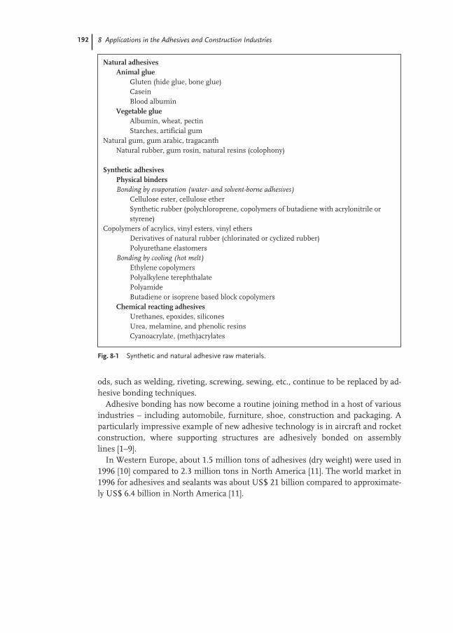
192 8 Applications in the Adhesives and Construction Industries
ods, such as welding, riveting, screwing, sewing, etc., continue to be replaced by ad-hesive bonding techniques.
Adhesive bonding has now become a routine joining method in a host of variousindustries – including automobile, furniture, shoe, construction and packaging. Aparticularly impressive example of new adhesive technology is in aircraft and rocketconstruction, where supporting structures are adhesively bonded on assemblylines [1–9].
In Western Europe, about 1.5 million tons of adhesives (dry weight) were used in1996 [10] compared to 2.3 million tons in North America [11]. The world market in1996 for adhesives and sealants was about US$ 21 billion compared to approximate-ly US$ 6.4 billion in North America [11].
Fig. 8-1 Synthetic and natural adhesive raw materials.
Natural adhesivesAnimal glue
Gluten (hide glue, bone glue)CaseinBlood albumin
Vegetable glueAlbumin, wheat, pectinStarches, artificial gum
Natural gum, gum arabic, tragacanthNatural rubber, gum rosin, natural resins (colophony)
Synthetic adhesivesPhysical bindersBonding by evaporation (water- and solvent-borne adhesives)
Cellulose ester, cellulose etherSynthetic rubber (polychloroprene, copolymers of butadiene with acrylonitrile orstyrene)
Copolymers of acrylics, vinyl esters, vinyl ethersDerivatives of natural rubber (chlorinated or cyclized rubber)Polyurethane elastomers
Bonding by cooling (hot melt)Ethylene copolymersPolyalkylene terephthalatePolyamideButadiene or isoprene based block copolymers
Chemical reacting adhesivesUrethanes, epoxides, siliconesUrea, melamine, and phenolic resinsCyanoacrylate, (meth)acrylates
8.2 Pressure-sensitive Adhesives 193
8.2
Pressure-sensitive Adhesives
Pressure sensitive adhesives (PSA) are highly viscous, viscoelastic liquids which ad-here to virtually all surfaces when pressed down gently. They are used in manufac-turing “easy to apply” self-adhesive products, such as labels and tapes. Pressure sen-sitive adhesives typically have permanent tack and adequate cohesion, so that furthercuring operations after applying the tape or label are generally unnecessary.
The first self-adhesive products were adhesive plasters [12], which were developedin the USA in 1845 by the medical doctor H.H. Day [13] and in Germany in 1882 byP. Beiersdorf [14]. The use of self-adhesive tapes for industrial purposes marked thebeginning of “dry-adhesion” technology. A new branch of industry began to coat var-ious support materials with pressure sensitive adhesives and to make self-adhesiveproducts from them. In 1935, R.S. Avery [15] invented a coating unit for self-adhe-sive paper labels using a wooden cigar box filled with an adhesive solution. The ad-hesive dripped through holes cut in the bottom, on to a roll of paper that ran below.This was probably the first curtain coating process.
Until the beginning of the 1970s, pressure sensitive articles were produced mainly by coating from organic solutions. Solvent-based rubber/resin mixtures andcomparatively smaller amounts of acrylate solutions were processed almost exclu-sively.
The first water-based acrylate dispersions were developed as long ago as the 1930s.They were produced on an industrial scale for the first time at the beginning of the1940s. However, acrylate dispersions for pressure sensitive adhesives were not intro-duced into the market until the beginning of the 1950s. The first areas of applicationwere self-adhesive book binding and map protection films. It was then possible forthe first time to make flexible PVC films self-adhesive without the need for a primer.This excellent property also made it possible to use dispersions for electrical insula-tion tapes. The use of self-adhesive films in advertising applications (e.g. promotion-al graphics, signs) began at virtually the same time. Furthermore, acrylate disper-sions satisfied the demand for removability without leaving a residue.
A continuous increase in pressure sensitive adhesive dispersion production oc-curred throughout 1960s. The rapid development of a number of new applicationsaccelerated this process. The crucial factor was the ground-breaking, systematicwork in the 1970s on high speed coatings technologies [16]. The development of newapplication equipment and corresponding high-solids dispersions has enabled coat-ing rates to be increased from less than 60 m min–1 to as high as 600–1000 m min–1
today.As so often it occurs in new technical developments, completely unexpected
advantages became evident with newly developed acrylic dispersions. The inherentproperties of polyacrylates made by emulsion polymerization enabled hithertounknown speeds during down-stream converting operations (i.e. slitting, die cuttingand stripping). It was also found that existing “solvent” coating units could be modi-fied to permit economical processing of aqueous dispersions. This increased effortsto use aqueous polyacrylate dispersions as pressure sensitive adhesives.

194 8 Applications in the Adhesives and Construction Industries
The total market demands for pressure sensitive adhesives (tapes and labels) isabout 300 000 tons of polymer in North America and about 200 000 tons in Europe.Aqueous polymer dispersions have a share of about 30 % in North America and 40 %in Europe. About 30 % in North America and 45 % in Europe are applied fromorganic solution while hot melts have a share of 40 % in North America and 15 % inEurope [17, 18].
8.2.1
Self-adhesive Labels
Self-adhesive labels (and decals) are pieces of paper, plastic film or metal foil coatedwith pressure sensitive adhesives which adhere to any solid surfaces after removalfrom a release liner. They are typically used to convey various kinds of information –for example, product or package contents, barcodes, price stickers, instructions, andtechnical data.
The most important adhesive raw material compositions for adhesive labels arepolyacrylate dispersions, styrene-butadiene rubber solutions, and styrene-butadiene-styrene (SBS) and styrene-isoprene-styrene (SIS) hot-melt adhesives. Permanent andremovable UV-cross-linkable acrylic hot-melt adhesives have recently also been in-troduced [19–22].
In the 1970s, Japanese paper label manufacturers started converting from rubbersolutions to water-borne systems because of very strict environmental protection reg-ulations, resulting in acrylic dispersions becoming the most important group of PSAraw materials in Japan. In North America, 85 % of the PSA label market was solventborn in 1975 [23] but in 1991 approximately two-thirds of the market was water-borne [24].
In Europe, the conversion was carried out in the 1980s and now the use of acrylicdispersions in self-adhesive products is widespread and well advanced. The impor-tance of acrylic dispersions continues to increase for reasons of environmental pro-tection (nonflammable, no hazardous solvents), high solids contents, good aging re-sistance, and excellent coating and processing properties.
About 2.9 billion m2 of self-adhesive labels were produced in Europe in 1996,corresponding to 35 % of world production. At average application rates of 24 g m–2,this corresponds to a demand for adhesives of 70 000 dry tons year–1 in Europe.
In North America 3.5 billion m2 of self adhesive labels were produced in 1999. As-suming the same coating weight, the adhesive demand in North America was 84 000dry tons year–1.
Polyacrylate dispersionsAdhesion and cohesion of polyacrylate dispersions can be varied over a broad rangeand matched to many applications through the type and combination of low Tg (“soft”)and high Tg (“hard”) monomers, the choice of auxiliaries, and the control of themolecular weight and process parameters [26–29]. Some examples are given below.The influence of glass transition temperature (Tg) of acrylic homopolymers on tack(according to A. Zosel [30, 31]) at various temperatures is shown in Fig. 8-2.
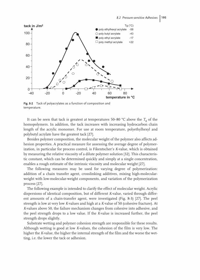
8.2 Pressure-sensitive Adhesives 195
It can be seen that tack is greatest at temperatures 50–80 °C above the Tg of thehomopolymers. In addition, the tack increases with increasing hydrocarbon chainlength of the acrylic monomer. For use at room temperature, polyethylhexyl andpolybutyl acrylate have the greatest tack [27].
Besides polymer composition, the molecular weight of the polymer also affects ad-hesion properties. A practical measure for assessing the average degree of polymer-ization, in particular for process control, is Fikentscher’s K-value, which is obtainedby measuring the relative viscosity of a dilute polymer solution [32]. This characteris-tic constant, which can be determined quickly and simply at a single concentration,enables a rough estimate of the intrinsic viscosity and molecular weight [27].
The following measures may be used for varying degree of polymerization: addition of a chain transfer agent, crosslinking additives, mixing high-molecular-weight with low-molecular-weight components, and variation of the polymerizationprocess [27].
The following example is intended to clarify the effect of molecular weight. Acrylicdispersions of identical composition, but of different K-value, varied through differ-ent amounts of a chain-transfer agent, were investigated (Fig. 8-3) [27]. The peelstrength is low at very low K-values and high at a K-value of 50 (cohesive fracture). AtK-values above 50, the failure mechanism changes from cohesive into adhesive, andthe peel strength drops to a low value. If the K-value is increased further, the peelstrength drops slightly.
Substrate wetting and polymer cohesion strength are responsible for these results.Although wetting is good at low K-values, the cohesion of the film is very low. Thehigher the K-value, the higher the internal strength of the film and the worse the wet-ting, i.e. the lower the tack or adhesion.
Fig. 8-2 Tack of polyacrylates as a function of composition and temperature.

196 8 Applications in the Adhesives and Construction Industries
However, adhesion is not affected by the average molecular weight alone, but alsoby the molecular weight distribution. This can be seen in Fig. 8-4, which shows the
Fig. 8-3 Peel strength as a function of molecular weight (K-value), according to W. Druschke [27].
20 500
5
10
15
20
K-value
peel strength in N / 2 cm peel rate 300 mm / min
80
adhesion failure
cohesion failure
Fig. 8-4 Peel strength as a function of the content of high-molecular-weight component, according to W. Druschke [27].
10:00
5
10
15
20
peel strength in N / 2 cm peel rate 300 mm / min
8:2 6:4 4:6 2:8 0:10
adhesion failure
cohesion failure
lower/higher molecular weight component

8.2 Pressure-sensitive Adhesives 197
peel strength of various mixtures of relatively high molecular weight acrylic polymer(K-value ca. 90) with low molecular weight material having the same composition (K-value ca. 55). With increasing content of high-molecular-weight component, i.e. an increase in the average degree of polymerization, the transition from cohesiveto adhesive fracture occurs again with a sudden drop in the measured peel values.The maximum peel strength is obtained at a high molecular weight component con-tent of 80 % [27].
When an acrylic dispersion with good low temperature peel strength (A) is mixedwith one having high cohesive strength (B), the actual performance of the mixturescan deviate strongly from a linear mixing relationship. As Fig. 8-5 shows, the shearvalues are significantly reduced by small amounts of dispersion A and low tempera-ture peel strength drops to zero at only 20 % of component B.
Interestingly, copolymerized functional monomers like acrylic acid, for example,results in an increase in cohesion (Fig. 8-6) and produces a significant increase in theshear strength.
The two contradictory requirements for high tack and needed internal strengthcan be best achieved in polyacrylate dispersions when adhesive and cohesive compo-nents are produced stepwise during the emulsion polymerization. The transfer offree radicals to pre-formed polymer chains results in the formation of branches,which crosslink on recombination. Crosslinking affects the viscoelastic behavior intwo ways: by slightly raising the glass transition temperature and by increasing themodulus level above the glass transition region. It also reduces the mobility of thecrosslinked polymer chains. This behavior is pronounced in polyacrylates and can be
Fig. 8-5 Shear values at 20 °C and low temperature peel strength at–23 °C depending on the mixing ratio of a high peel dispersion A and a high shear dispersion B [33]
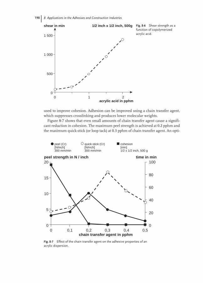
198 8 Applications in the Adhesives and Construction Industries
used to improve cohesion. Adhesion can be improved using a chain transfer agent,which suppresses crosslinking and produces lower molecular weights.
Figure 8-7 shows that even small amounts of chain transfer agent cause a signifi-cant reduction in cohesion. The maximum peel strength is achieved at 0.2 pphm andthe maximum quick-stick (or loop tack) at 0.3 pphm of chain transfer agent. An opti-
Fig. 8-6 Shear strength as afunction of copolymerizedacrylic acid.
00
500
1 000
1 500
acrylic acid in pphm
shear in min
1 2
1/2 inch x 1/2 inch, 500g
Fig. 8-7 Effect of the chain transfer agent on the adhesive properties of anacrylic dispersion.
quick-stick (Cr)[N/inch]300 mm/min
peel (Cr)[N/inch]300 mm/min
cohesion[min] 1/2 x 1/2 inch, 500 g
00
5
10
15
20peel strength in N / inch
chain transfer agent in pphm0,1 0,2 0,3 0,4 0,5
20
40
60
100
0
80
time in min
8.2 Pressure-sensitive Adhesives 199
mum balance between plasticity and bond strength is clearly achieved at a certaindegree of crosslinking.
The polyacrylate dispersions optimized in this way for pressure sensitive ad-hesives are produced and supplied with solids contents between 50 % and 70 %.Average particle sizes are typically between 100 nm and 1000 nm. However, disper-sions with a high solids content (> 60 %) and low viscosity (<500 mPa s) need to havea bimodal or multimodal particle size distributions. The viscosities of most commer-cial products are generally between 10 and 1000 mPa s but high-viscosity dispersions– greater than 10 000 mPa s – are also used in certain packaging applications. Poly-mers used in pressure sensitive applications have glass transition temperatures ofbetween –60 and –20 °C.
Formulation modificationsAcrylate dispersions can be used directly in only a small number of applications.Technical or economic considerations often make modification necessary [34]:– optimization and refinement of the adhesion properties;– production of a large number of self-adhesive products using a small number of
starting materials;– optimization of the formulation from a commercial point of view; and– matching of the viscosity, rheology and wetting behavior of the adhesive to the pro-
posed coating method and substrate.This is generally done by mixing acrylic dispersions with one another, and adding
tackifying resins and plasticizers. Wetting agents, defoamers and thickeners areadded to adapt the adhesive to the prevailing coating conditions. Fillers or pigmentsare used to color the adhesive material (e.g. brown adhesive tapes for packaging) orto achieve special effects (e.g. zinc oxide in medical tapes).
Dispersion mixturesIn some self-adhesive products (for example, protective films), the goal is a weak tackwhich does not increase after extended bonding times. These products are based onspecial self-crosslinking acrylics. In order to improve the tack, cohesive productswith good tack are admixed. In certain applications requiring chemical resistance(e.g. against plasticizers), a dispersion with superior resistance can be mixed in cer-tain proportions to increase the overall formulation performance. In wet labeling ap-plications (e.g. bottles), which previously used “natural adhesives” such as casein, ablend of acrylic dispersions, natural latex, and wax dispersion have been employed.Note that blends of acrylics and styrene-butadiene latex (SBR), for example, producedry films which are opaque – because of differences in refractive index. The formu-lator can take advantage of this effect to impart opacity to a substrate. But it is im-portant to note that when blending acrylics and SBR, water resistance of the driedfilms can be affected in unexpected ways (Fig. 8-8).

200 8 Applications in the Adhesives and Construction Industries
Addition of tackifying resinsResins are used to improve the tack of pressure sensitive adhesives. They must becompatible with the polymer (i.e. mixture has a single Tg) and modify its viscoelasticproperties resulting in improved polymer flow characteristics, substrate wetting, andadhesive bond formation.
The most suitable products for improving the tack of polyacrylates are modifiednatural resins, such as dimerized or hydrogenated gum rosins and esterified abieticacids. With resins whose softening points are about 70 °C, pressure sensitive adhe-sives with high shear strength but relatively low tack are obtained. If these resins arecombined with softer resins, the tack is significantly increased. Besides the generalincrease in tack, addition of resin also specifically increases the adhesion to poly-olefin surfaces. However, the addition of resin may impair the aging resistance ofthe adhesive. Preferred applications for acrylate–resin combinations are paper labelsand double-sided adhesive tapes (for example, carpet laying tapes). Hydrocarbonresins based on petroleum oil derivatives are preferred for tackifying styrene–butadi-ene dispersions [24, 35].
To retain the advantage of the “solvent-free” feature offered by polymer disper-sions, resin dispersions should be used instead of resin solutions. Resin dispersionsare available, for example, from Akzo Nobel/EKA Chemicals (Netherlands, USA),DRT/ND Dispersions (France, USA), and Hercules (Germany, USA). However, itshould be noted that a resin dispersion generally reduces cohesion to a greater extentthan does a resin solution – because of the surfactants present. In addition, the waterresistance, evident from blushing, is often reduced. Polymeric tackifier has been re-ported to increase the elastic properties of a pressure sensitive adhesive resulting inimproved peel strengths, especially at high peel rates [36].
Fig. 8-8 Water resistance of dried PSA films depending on the blend ratioacrylic/styrene-butadiene latex.
0
10
20
30
40
50
60
70
100/0 80/20 50/50 20/80 0/100
PSA Blend Ratio (Acrylate / SBR)
Wat
er U
pd
ate
(%,
afte
r 24
hrs
)

8.2 Pressure-sensitive Adhesives 201
Addition of plasticizersPlasticizers increase the flow properties of the adhesive film. This results in fasterwetting of the substrate surface to be bonded and consequently increases the initialpeel strength. This naturally occurs at the expense of cohesion and heat resistance.In contrast to resins, which normally increase the Tg of the adhesive polymer, plasti-cizers decrease the Tg and make the polymer softer. The tack-increasing effect ofresins can be augmented by addition of small amounts of plasticizers. Particularly inthe case of resins with high softening point that have a deadening action on theadhesive, addition of a small amount of plasticizer results in a lowering of the soft-ening point. A resin-plasticizer combination consequently increases the tack veryeffectively. Small amounts of plasticizer (2–5 %) are frequently added to the acrylicdispersions in order to obtain gentler removal.
The main plasticizers used are the classical plasticizers (i.e. phthalates such asDOP, DBP and DIDP). Adipates are also suitable as polymeric plasticizers, but arerarely used owing to price reasons and their somewhat lower compatibility. A specialpolymeric plasticizer polypropylene glycol alkyl phenyl ether (Plastilit 3060) fromBASF, has extremely good compatibility with acrylate polymers and does not mi-grate. This product has now proven highly successful in a number of applications(including pressure sensitive adhesives, acrylic sealants and paints).
Thickening of pressure sensitive adhesive dispersionsSuitable protective colloids and thickeners include animal glues, gelatin, casein, veg-etable gum, dextrins, enzymatically digested starches, alginates, cellulose derivatives(methyl-, carboxymethyl- and hydroxyethylcellulose), polyvinyl alcohols, polyacrylicacids, polyacrylamides and polyvinylpyrrolidones, amongst others. They increase theviscosity and water retention, modify the rheology for optimum coatability andspeed, and in addition generally also improve the mechanical stability and compati-bility of the dispersions with electrolytes and fillers. In order to achieve optimum re-sults, precise metering and suitable selection and combination of the protective col-loids and thickeners are necessary. Since the water resistance of polymer films fromdispersion decreases with increasing addition of thickener, the proportion of thick-ener should always be minimized.
Addition of wetting agentsThickened dispersions generally have little problem wetting various surfaces. Evensurfaces with extremely low surface tension, such as silicone paper and corona treat-ed polyolefin film, can be wetted under the uniform pressure imparted by the liquidadhesive on to the substrate during the coating operation. A high resistance to flow(i.e. high viscosity) prevents subsequent dewetting and minimizes the occurrence ofcoating flaws (e.g. fish eyes).
The situation is quite different, however, in high speed, low viscosity coating sys-tems such as modern vario-gravure where the dispersion film, which is initially uni-formly distributed on the surface, re-coalesces relatively quickly if its surface tensionis excessively high. In this case, the surface tension of the pressure sensitive adhe-sive dispersion must be matched to that of the substrate to be coated (film or silicone
202 8 Applications in the Adhesives and Construction Industries
paper). This is achieved by adding corresponding surfactants, so-called wettingagents. These surfactants naturally increase the risk of foaming and in some casesincrease the water sensitivity of the adhesive film. The amount added should againbe kept as low as possible. The sodium salt of a sulfosuccinic acid ester (Lumiten I-SC,BASF, Aerosol OT70-PG, Cytec) is a relatively low-foaming surfactant whose partic-ular effectiveness as wetting agent arises due to its tendency to migrate to newlyformed surfaces very quickly.
Addition of antifoamsSurfactants (emulsifiers and wetting agents) often cause foaming, which results incoating defects particularly when operating at high speeds. This is prevented by ad-dition of antifoams. The effectiveness of antifoams, for example higher alcohols,non-ionogenic acetylenic compounds, or aliphatic hydrocarbons with non-ionogenicconstituents, varies depending on the other auxiliaries present in the formulationand in addition can drop with increasing storage time. The antifoam may float, settleor diffuse into the polymer and thus, is no longer available at the liquid–air interfacewhere it is needed. It is therefore recommended that the dilute antifoam only beadded immediately before processing or, even better, sprayed directly on to the foamsurface by means of an atomizer if needed.
It should be noted that excessive amounts can impair flow of the dispersion, which rapidly results in flaws (pinholes, fisheyes) in the coating. A general rule ofthumb is that the amount of antifoam in initial experiments is 10 % of the amount ofwetting agent, i.e., for example, one part of wetting agent and 0.1 part of antifoamper 100 parts of dispersion. Owing to interaction with the auxiliaries in the disper-sion, the most effective antifoam for each adhesive must be determined experimen-tally.
Companies which offer suitable antifoams include: Air Products and ChemicalsInc., Allentown PA (USA); BASF AG/Corporation, Ludwigshafen/Mount Olive(Germany/USA); Ashland Chemical Co., Drew Industrial Division, Boonton, NJ(USA), or Drew Ameroid Europe, Ultra Additives Inc, Patterson, NJ (USA); HenkelAG, Düsseldorf (Germany); ICI Surfactants, Middlesbrough (England), MuenzigChemie, Heibronn (Germany).
Addition of fillers or pigmentsFillers cause significant deadening of the adhesive, which can be compensated againby a slightly increased amount of tackifier. In labels made from relatively thin paper,small amounts of fillers or pigments can be added in order to increase the hidingpower.
Zinc oxide has proven successful as an antiseptic, moisture-absorbent filler in rub-ber-based medical adhesive tapes. In contrast, modern medical adhesive tapes withnon-woven or woven fabric as support material use polyacrylates owing to their low-er skin irritation action. These contain virtually no filler. If necessary, white col-oration is produced using TiO2.
Fine sand (SiO2) also has a very strong deadening action. Even on addition of only10 %, the tack can no longer be measured. Calcium carbonate filler exhibits much

8.2 Pressure-sensitive Adhesives 203
better behavior. The smallest reduction in tack is caused by titanium dioxide, but thisis relatively expensive.
For homogeneous incorporation of fillers or pigments, it is advantageous to pre-pare a paste with a little water. Additives to the water, such as ammonia, polyacrylicacid salts and polyphosphates, aid in dispersing and also prevent the filler particlesfrom subsequently re-agglomerating. A “wetting fluid” comprising one part of am-monia, one part of Pigment Dispersant A (BASF), one part of Calgon N (sodiumpolyphosphate, Benkiser, Ladenburg) and 97 parts of water, to which the pigmentsare mixed to yield a paste, has proven successful.
Protection against microorganismsThe risk of bacterial, yeast or fungal contamination is naturally the greatest in theneutral or weakly basic pH range. This pH range is in most cases established duringmodification as it also provides the best compatibility of the dispersion with formu-lation additives. Preservatives used include formols, benzisothiazolinones (Proxel,Avecia, Wilmington, DE, USA and Manchester, UK), isothiazolones (Kathon , Rohmand Haas, Philadelphia, PA, USA, Rohm and Haas France SA, Valboonne-Cedex,France). Other preservative suppliers include Riedel-de Haën AG (Germany), TroyCorporation, Florham Park, NJ (USA) and Arch Chemicals (Paris, France andCheshire, Connecticut, USA).
General notes on modificationThe following is a suitable compounding procedure: the pH of the starting disper-sion is firstly increased in order to improve compatibility. Secondary acrylate disper-sions are then added, followed by resin solution or resin dispersion, other tackifiers,plasticizers and, if used, a pigment and/or filler paste. The final step is adjustment tothe processing solids content and viscosity by thickening, dilution and addition ofwetting agent.
Guiding formulations1. Acrylic permanent paper label (resin tackified)
Wet wt.Polymer dispersion Acrylic dispersion, 60–70 % 116Tackifier dispersion Tacolyn 1070, 55 %*
or Snowtack 880G, 57 %† 36.4Defoamer Drewplus L-108‡ 0.1–0.5Wetting agent Lumiten I-SC§ 0.5–1.5Neutralizing agent Ammonia (10 %) to pH 7.5–8.5 0–2Water As required to max. 65 % solidsRheology modifier As needed for coating head 0–2Application rate: 20 g solid m–2
Suppliers: *Hercules, Wilmington, DE, USA; †Akzo Nobel, Toronto, Ontario, Canada; ‡Ashland/Drew Chemical; §BASF, Charlotte, NC, USA

204 8 Applications in the Adhesives and Construction Industries
2. All-temperature paper label (non-tackified)Polymer dispersion Acrylic dispersion 100Neutralizing agent Ammonia (10 %) to pH 7.5–8.5 3–5Wetting agent Aerosol OT70-PG# 0.5–1Rheology modifier As needed for coating head 0–2Water To maximum 65 % solidsApplication rate: 20 g solid m–2
Suppliers: #Cytec
Styrene-butadiene dispersionsIn North America approximately 5–10 % of the dispersions used for labels are basedon styrene-butadiene rubber (SBR) [24]. SBR used in pressure sensitive adhesivesare produced by emulsion polymerization with butadiene contents typically between25 and 45 %. With careful control of process conditions (temperature, styrene and butadiene feed rates) and ingredient feed levels (chain transfer agent, initiator,monomers), intermediate molecular weight, lightly cross-linked elastomers havingan excellent balance of cohesive and adhesive properties can be obtained.
SBR based systems are primarily used in cost-sensitive paper label applications;they are not used, when clear films with long-term UV or heat aging resistance arerequired. While the hydrophobic nature of SBR promotes superior initial tack andadhesion to low energy substrates, this feature also makes them susceptible to plas-ticizer attack.
Compared to tackified acrylic PSA, styrene-butadiene based systems normally re-quire significantly increased tackifier contents (up to 2 times) to achieve desired tackand peels levels. SBR are compatible with both commercial rosin and hydrocarbonbased tackifying resins. Differences in chemical composition, softening point, andsurfactant stabilizers in tackifier dispersions can have a significant impact on thepeel-shear balance of the formulated product [26]. Since commercial SBR are avail-able at relatively low solids contents (ca. 50–55 %), the formulated adhesives havehigher water contents compared to those based on acrylics. This subsequently trans-lates into slower line speeds and/or higher energy demand during the drying opera-tion. An antioxidant would be recommended for SBR applications requiring extend-ed stability against heat exposure or oxygen attack.
Guiding formulationSBR permanent paper label (resin tackified)
Wet wt.Polymer dispersion Butonal NS 166, 51 %* 63.8Tackifier dispersion Aquatack 6085, 60 % 36.2Defoamer, wetting agent, and rheology modifiers added as needed.Application rate: 20 g solid m–2
Suppliers: *BASF Corporation, Charlotte, NC, USA; Arizona Chemical, Panama City, FL, USA

8.2 Pressure-sensitive Adhesives 205
CoatingSelf-adhesive labels and films are produced by coating support materials such as sil-icone release liner, paper stock, and film webs with pressure sensitive adhesives(Fig. 8-9). Various coating methods are used to ensure the correct amount of adhe-sive is applied per unit area of substrate [37–40]. High viscosity adhesives can be ap-plied using a knife-over-roll coater. In reverse-roll coating, the adhesive is transferredto the substrate web after being taken up by an application roll rotating in a directionopposite to that of the web. Knife coaters and reverse roll coaters are traditional sys-tems originally developed for coating solvent-based adhesives. But with aqueous dis-persions, coating speeds of only 100–120 m min–1 are possible with these coatingmethods – at application rates of about 20 g m–2. For higher production speeds,Meyer rod (150–250 m min–1), reverse gravure (300 m min–1), vario gravure(600+ m min–1), and slot die technologies are available. These systems require low-viscosity dispersions and their development in the 1960s paved the way for a majorbreakthrough by acrylate dispersions for mass-produced pressure sensitive articlesin Europe. Improvements in coating speeds, reliability, coating consistency, andproduct quality led to lower production costs and continuation of the trend to water-based emulsion coating technologies.
Reverse gravure was introduced by BASF at the beginning of the 1980s for pres-sure sensitive adhesive processing and basically consists of a blade pressed on to agravure cylinder rotating in a pan of wet adhesive in a direction opposite to that ofthe web. Adhesive is transferred from the pan into the recesses of the gravure rolland then on to the web. The blade and roll assembly are primarily responsible formetering on the correct quantity of wet adhesive and establishing a consistent, defectfree adhesive coating. Gravure rolls (Fig. 8-10) with 14 to 18 lines cm–1 give a drycoating weight of about 20 g m–2. A gravure roll with 36 lines cm–1 gives, for exam-ple, about 10 g m–2 (in each case with an approximately 50 % solids adhesive). If de-sired, the coating weight can be varied slightly by adjusting the blade position and bymodifying the viscosity of the adhesive. For significant changes, a roll with a differ-ent grid must be used.
When high reverse-gravure coating speeds (600+ m min–1) are attempted, coatingweight is found to drop off drastically above about 300 m min–1. This behavior occursat high speeds because of the shorter residence time of the gravure roll in the dis-persion reservoir – i.e., so short that the gravure line cells are no longer completely
Fig. 8-9 Schematic representation of PSA label coater.
Releaseliner
SteamDryerCoating head
Unwind Rewind
Laminatingstation
Backing

206 8 Applications in the Adhesives and Construction Industries
filled and too little dispersion is applied to the web. However, if the dispersion isforced into the engraving under pressure, it is possible to vary coating weight over abroader range, even with a constant number of lines. For example, application ratesfrom 15 to 30 g m–2 can be achieved at 600 m min–1 with an 18 lines cm–1 gravure rolland from 20 to 40 g m–2 with a 14 lines cm–1 gravure roll.
Vario gravure is a substantial refinement of the standard reverse gravure method(Fig. 8-11). The side seal consists of two polyethylene “margin wipes” pressedagainst the polished ends of the gravure roll. Two grooves, providing pressure re-lease and lubrication, are incorporated into each margin wipe. Rubber parts are alsobuilt into the margin wipes to seal the side edges of the coating blade – the entire“casting box” assembly is sealed by a lateral force applied on to the sides of two mar-gin wipes. The upper blade is additionally pressed against the gravure roll surface,which simultaneously prevents air being drawn in and results in very low air en-trainment (i.e. low foaming).
Fig. 8-11 Vario gravure coating head.
margin wipe
adhesive
blade adjustment
blade adjustment
out
substrate
inPSA dispersion
Fig. 8-10 Portion of a gravure roll (left), cross-sectional schematic (right).(a) 10–20 µm chrome layer, (b) 10–15 µm nickel layer, (c) 70–250 µm copper layer, (d) steel base roll.

8.2 Pressure-sensitive Adhesives 207
Coating weight is controlled mainly via the pump pressure, designed to operatewithout pulsation (Mohno pump). Due to the excess pressure prevailing in the cast-ing box (0.2–0.6 bar), not only are the recesses of the gravure roll surface filled, but afilm, i.e. an excess, is also applied on to the roll. This is the only way that a coatingweight of 20 g m–2 can be maintained at higher speeds (400–600+ m min–1). The flowrate of wet adhesive through the pump can also be coupled to the web speed in orderto keep coating weight constant during speed changes.
Water based pessure sensitive adhesives can also be directly applied on to the sub-strate web using a slot die coater (Fig. 8-12). Die coating is widespread in the USA(est. 60–70 % of total label production), but is only used occasionally in Europe.
Coating weight can be easily varied over a broad range at different web speeds.Uniform distribution of medium-viscosity adhesive over the web width is achievedwith a special die geometry where the outlet aperture is larger at the web edges thanin the center. This method provides an impressive final coating – characterized byunusual levelness.
8.2.2
Self-adhesive Tapes
Self-adhesive tapes are flexible substrates coated with pressure sensitive adhesiveswhich are wound up in roll form and cut to different widths.
About 4.3 billion m2 of adhesive tapes were produced in Europe in 1996 [41]. Sev-enty percent of these are packaging tapes, while the remainder are double-sided ad-hesive tapes, masking tapes and other adhesive tapes (medical tapes, electrical insu-lation tapes, household tapes, office tapes and protective films). Solvent-based, resin-modified rubber solutions, used mainly for packaging adhesive tapes, are still domi-nant in this segment. The stringent requirements on tack and cohesion for tapes
adhesive
width adjustment of slot die opening
die
die lip offset adjustment
PSA dispersion feed line
substrate
Fig. 8-12 Slot-die coating head.

208 8 Applications in the Adhesives and Construction Industries
have still not been achieved by any other adhesive system in such a balanced way.The proportion of water-borne adhesives used in the European tape market is about14 % [19]. Water-borne adhesives are mainly used for double-sided adhesive tapesand electrical insulation tapes.
In North America, about 4.5 billion m2 of adhesive tapes were produced in 1999.Assuming an average coating weight of 40 g m–2, this corresponds to a polymer de-mand of 180 000 tons year–1. About 70 % are used for industrial and packaging tapes,the rest is used for consumer, surgical, electrical and masking tapes [18]. Water-borne systems are used mainly to produce carton-sealing tapes.
Packaging tapesPackaging tapes are required to form the contact points necessary for box or cartonclosure (typically corrugated), even on gentle pressure. This means that the adhesivemust have high tack and good adhesion. In Europe, natural rubber is predominatelyused to meet these requirements. Although acrylate dispersions have better agingresistance, they have lower tack at the high cohesion levels needed.
Experiments have shown that the lower tack values can be fully compensatedthrough increased positioning or “application” pressure. In North America, cartonsealing tapes made from oriented polypropylene and water-borne acrylic PSA arealso produced. Anchoring of the dispersion adhesive to the polypropylene film isachieved by corona pretreatment. A release coating is not necessary. The main re-quirements for this application are withstanding the continuous shear and low-anglepeel forces transmitted to the tape at the carton closure. Coating weights of about15–35 g dry adhesive m–2 are typically used. Paper backed tapes, such as maskingtapes, require coating weights in the 30–60 g m–2 range.
Foil duct tapesFoil duct tapes, used in North America for heating, ventilation and air conditioningsystems, are constructed of 50 µm aluminum foil coated with 50–100 µm of anacrylic dispersion PSA to provide high adhesion and functionality at extreme “use”temperatures. Once coated, the adhesive is covered with a release liner to prevent ad-hesion to the top side of the foil and subsequent blocking of the tape roll. Some foiltapes use strands of fiber reinforcement laminated between foil and kraft paper lay-ers to improve tensile strength [24].
Electrical tapesFlexible PVC tapes of various types are predominately used for electrical insulationpurposes and to a lesser extent, for pipe insulation. In Europe, acrylate dispersionshave been used in the manufacture of electrical tapes for more than four decades.Coating weights of ca. 25 g dry adhesive m–2 are typically used. Their advantage isthat they can be coated on to flexible PVC films without a primer. However, the useof dispersions requires a high level of knowledge of the compositions and interac-tions between particular flexible PVC substrates and acrylic adhesives. As a result,suitable dispersions must be carefully selected and in many cases, it is necessary touse more than one dispersion type to achieve required performance levels. Of prime

8.2 Pressure-sensitive Adhesives 209
importance are plasticizer resistance screening tests on the adhesive, carried out inorder to examine for undesired changes in adhesive properties due to plasticizer mi-gration from the PVC film.
Masking tapesThis term covers tapes for protecting surfaces during painting, sand blasting, etc.The support material used is crepe paper of various quality and extensibility with nat-ural rubber predominately used in the adhesive. Nonetheless, adhesives made frommixtures of certain acrylate dispersions are highly suitable for “painters-grade”masking tapes. Key requirements of masking tapes include adequate adhesion andthen easy removability without leaving a residue – even after extended storage timesor after exposure at high ambient temperatures. Coating weights of ca. 45 g m–2 dryadhesive are used.
Double-sided adhesive tapesDouble-sided adhesive tapes or “mounting” tapes have been used to replace conven-tional attachment methods in a range of different end-use applications. They areused on a wide variety of surfaces, for example, as an assembly aid in the automotiveindustry, in graphic arts for plate mounting and in home and office uses that previ-ously required mechanical fasteners (e.g. nails and screws). The central support sub-strate used includes non-wovens, textile fabrics, foams and other materials and insome cases, support-free mounting tapes are also available. Foam mounting tapesare especially useful because the foam provides stress distribution for increasedshear strengths.
While acrylate dispersions are often used, the most demanding applications em-ploy solvent based acrylates that are subsequently crosslinked chemically or thermal-ly to achieve performance requirements. In applications requiring exceptionally highadhesive coating weights (up to 100 g dry adhesive m–2), dispersions having highsolids contents have been advantageous to increase drying rates during the coatingoperation.
Protective filmsProtective films are used to protect high-value items like painted or polished metalsurfaces (e.g. automobile paint finish), anodized aluminum, acrylic sheets, lac-quered furniture surfaces and automotive carpets from scratching, soiling and mar-ring during manufacture, shipping and installation. A range of support substratesare used, including paper, flexible PVC, PE-, PP- and polyester films [24]. Here too,acrylate dispersions are being used instead of the cross-linkable acrylate solutionsused in the past. In particular, self-crosslinking emulsion adhesives providing cru-cial cohesion and anchoring to PE films have been developed especially for protectivefilms [24, 42]. Coating weights of about 5 g dry adhesive m–2 are employed.

210 8 Applications in the Adhesives and Construction Industries
8.2.3
Test Methods
Tack, adhesion and cohesion are the three main properties required of a pressuresensitive adhesive.
The tack is the ability of a pressure sensitive adhesive to adhere immediately to asurface. A pressure sensitive adhesive with good tack forms the contact points nec-essary for adhesion of the tape or label after only brief contact with a substrate. Sol-vent based rubber adhesives can have very good tack, depending on the formulation.Acrylate solutions and dispersions, as well as hot-melt contact adhesives, meet theusual demands.
The peel strength (adhesion) is a measure of the separating force necessary to peel alabel or tape off from the surface to which it was applied. The term describes thestrength of adhesion or “grab” to a surface. Acrylate compositions require a fewhours before achieving full adhesion. Rubber adhesives and hot-melt contact adhe-sives exhibit high peel values after only a relatively short contact time.
The shear strength (cohesion) is the ability of a pressure sensitive adhesive to with-stand applied forces or loads. Good shear strength is required when labels are stuckto curved surfaces and for processing purposes, i.e. die-cuttability, slitting and tominimize edge-ooze of roll products. When assessing shear strength, a distinctionmust be made between the performance at room temperature and at elevated tem-peratures. Pressure sensitive adhesives designed having adequate room temperatureshear strengths should also be formulated to resist failure at higher service tempera-tures. While acrylic dispersions exhibit only a slight change in shear strength at ele-vated temperatures (due to internal gel structure), hot-melt adhesives tend to softenand the shear strength drops significantly.
Depending on the use, different requirements are made of pressure sensitive ad-hesives with respect to adhesion and cohesion (Fig. 8-13).
Fig. 8-13 Adhesion level of self-adhesive articles.
cohesion
adhesion
removablelabels
permanentlabels
protectivefilms
packagingtapes

8.2 Pressure-sensitive Adhesives 211
A protective film must be removable without leaving a residue, i.e. must have verylow adhesion, even after long bonding times, in conjunction with high cohesivestrength. By contrast, a packaging tape must stick immediately and durably, i.e.must have both very high adhesion, even after brief contact, and high cohesion. Inpaper labels for permanent bonding, high adhesion is needed in order to ensure rap-id bonding to the various surfaces, while the cohesion need only be sufficiently highto avoid formation of adhesive filaments during label stamping and stripping opera-tions. Removable labels have low adhesion and sufficient cohesion for removal.
Numerous methods are available for quantifying these different property profiles.For better comparison of the properties of pressure sensitive adhesives, standardizedtest methods have been developed by various organizations, including:– FINAT – Fédération Internationale des Fabricants et Transformateurs d’Adhésifs
et Thermocollants sur Papiers et autres Supports– PSTC – Pressure Sensitive Tape Council.
These and other PSA test methods were compared in a review article by R.P.Muny [43]. One common feature of these established test methods is that they are alldestructive measurements. In the first phase of the test, a bond is formed on contactof pressure sensitive adhesive with the substrate. Initially, depending on the appliedpressure, only individual, small points of adhesion form, whose number and size in-crease during the contact phase due to elastic deformation, viscous flow and wettingof the substrate with the adhesive. Contact formation is, therefore, determined bymechanical behavior and surface properties, such as surface tension, roughness, andadsorbate layers. Other important influencing factors are contact time, contact pres-sure and temperature. During the second phase, the bond is separated under the ac-tion of a tensile force, with the bond being deformed. Both processes, i.e. contact for-mation and separation, are influenced by the test conditions, which are different ineach measurement method [27, 30, 44].
It is conceivable to carry out nondestructive measurement of an adhesive joint us-ing nuclear magnetic resonance methods (NMR imaging). However, such methodsare still under development [45].
Peel strengthThe most common adhesion test is peel strength testing [27], in which the forcewhich occurs on peeling the adhesive layer off from a substrate is measured.
Conditioned test strips with a certain width are rolled on to test panels using aroller with a defined weight. Stainless steel with a surface of defined roughness isused in method PSTC-1 while glass is employed in the FINAT method. But in bothcases, after a certain dwell or bonding time, the peel measurement is carried out in amechanical testing machine at constant peel rate and at a peel angle of either 180° asin Fig. 8-14, or alternatively at 90°. There are various standards for the peel strengthtest which differ essentially through the type of cleaning of the test panels and thebonding times. For example, the bonding time is a maximum of 1 min in the PSTCtest, and 20 min and 24 h in the FINAT method. Since the dwell time has a signifi-cant effect on the level of adhesion, different values are obtained by the two methodsmentioned [27].

212 8 Applications in the Adhesives and Construction Industries
Even after a bonding time of 1 h, the wetting process is not complete in all cases(Fig. 8-15). Besides the immediate value, a measurement is therefore often taken af-ter, for example, a bonding time of 24 h, corresponding to FINAT test method 1 [27].
Besides numerous other authors [46–49], the main contributor to understandingof the very complex peel mechanism in self-adhesive tapes is Kaelble [50, 51]. He hasshown that the peel strength is dependent on the moduli of elasticity and the thick-nesses of both the adhesive and the support, on the peel angle, and the interactionforces at the adhesive-substrate interface [27]. Peel strength also depends on temper-ature and peel rate. At a given temperature, the peel strength increases with increas-ing peel rate. At low peel rates the viscous properties are dominant, polymer mole-
Fig. 8-15 Peel strength of an acrylic pressure sensitive adhesive depend-ing on the dwell time, according to W. Druschke [27].
peel strength in N / 2 cmdwell time
10 min
30 min
1 h
3 h
24 h
4,0
4,6
5,3
5,5
8,0
Fig. 8-14 Peel strength at 180° [27].
method dwell time
A.F.E.R.A. 4001 max. 10 min
PSTC-1 max. 1 min
FINAT 20 min24 h
clamp
clamp
adhesive
support substrate (paper, film)
test substrate(steel, glass, polyolefin)

8.2 Pressure-sensitive Adhesives 213
cules have time to slide past one another, to disentangle and to dissipate energy. Athigh peel rates the elastic properties of the polymer network predominate, the poly-mer molecules are not able to disentangle, and so the polymer modulus or “stiff-ness” increases. Since the mobility of polymer chains increase with increasing tem-perature, the peel strength will decrease as well – at a constant peel rate [52].
TackTack is defined as the limiting value of the adhesion as the contact time approacheszero. Targets for tack measurements are shortest possible contact time and lowestpossible contact pressure. With this aim, a number of methods have been devel-oped [53, 54]. The best known tack measurement methods are quick-stick, probetack, Zosel tack and rolling ball [27]. All these methods are ultimately a refinement ofthe subjective finger test, which still plays significant role in forming a qualitativepractical opinion [27].
In the quick-stick method corresponding to FINAT test method No. 9, a test stripis formed into a loop, brought into contact with a glass plate and then immediatelypeeled off again, as shown in Fig. 8-16.
This FINAT method differs from the PSTC (PSTC-5) quick-stick method, in whichpeeling is carried out at an angle of 90° without formation of a loop [55]. The Tag andLabel Manufacturers Institute (TLMI, Iowa City, IA 319-337-8247) specifies a looptack test and within their manual, includes a host of useful TAPPI and ASTM meth-ods for testing paper and plastic film substrates used in pressure sensitive labels, re-spectively.
Fig. 8-16 Quick-stick tack measurement [27].
clamp
clampsupport substrate
support substrate
test plate(steel, glass, polyolefin)
adhesive
adhesive

214 8 Applications in the Adhesives and Construction Industries
The advantage of the quick-stick methods compared with other tack measurementmethods is that the test can be carried out in any mechanical test machine with onlyminimal contact pressures. Disadvantages of the method include a relatively longcontact time, different contact times within a test area and different contact areas.Moreover, the peel angle is not constant in the FINAT method.
A widespread tack measurement method is the probe tack method proposed byWetzel [56] and refined by Hammond [57]. In this method, known as the Polykenprobe tack method (Fig. 8-17), a cylindrical ram with a diameter of 0.5 cm is pressedfrom below against the adhesive layer at a defined pressure and speed and removedagain at a defined speed after a certain contact time (see ASTM D2979-71).
Contact times in the region of 0.1 s are possible using this method. The fact thatthe measurements can be carried out simply and quickly and the conditions variedeasily and widely is advantageous. However, a very complex instrument is necessary.In addition, the very small ram contact area of only 0.2 cm2 means that only small ar-eas of the adhesive layer are measured. Air inclusions in the adhesive layer can resultin incomplete wetting of the piston surface [27].
An instrument developed at BASF by A. Zosel [30–31] for fundamental stud-ies [58–63] on the theory of adhesion operates on a similar principle to the probe tackmethod (Fig. 8-18).
The polymer to be tested is applied to a flat steel plate in a defined layer thicknessand dried. With the aid of an electric motor, the sample platform within the testchamber is moved against the piston and then away again in the opposite directionafter contact. The shortest contact time that can be set is 0.01 s. The piston is con-nected to a piezoelectric force transducer. Variable parameters are the piston area,contact force, contact time and approach speed of the tack experiment. The instru-ment allows measurements from –50 °C to 200 °C. This method also allows basicstudies with variation of other key parameters, such as separation speed, surface ten-sion of the test piston, and composition of the adhesive layer [64, 65].
Fig. 8-17 Polyken Probe Tack method [27].
adhesive
weight weight
support support
piston
substrate
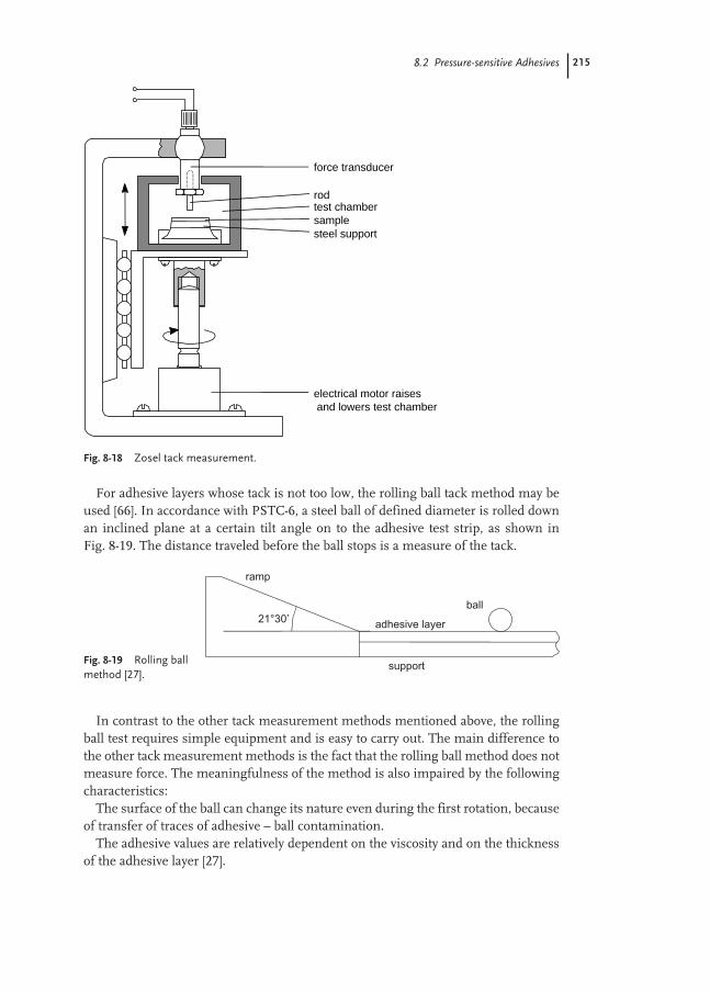
8.2 Pressure-sensitive Adhesives 215
For adhesive layers whose tack is not too low, the rolling ball tack method may beused [66]. In accordance with PSTC-6, a steel ball of defined diameter is rolled downan inclined plane at a certain tilt angle on to the adhesive test strip, as shown inFig. 8-19. The distance traveled before the ball stops is a measure of the tack.
In contrast to the other tack measurement methods mentioned above, the rollingball test requires simple equipment and is easy to carry out. The main difference tothe other tack measurement methods is the fact that the rolling ball method does notmeasure force. The meaningfulness of the method is also impaired by the followingcharacteristics:
The surface of the ball can change its nature even during the first rotation, becauseof transfer of traces of adhesive – ball contamination.
The adhesive values are relatively dependent on the viscosity and on the thicknessof the adhesive layer [27].
Fig. 8-18 Zosel tack measurement.
electrical motor raises and lowers test chamber
steel supportsampletest chamberrod
force transducer
Fig. 8-19 Rolling ballmethod [27].

216 8 Applications in the Adhesives and Construction Industries
Reproducibility of adhesion measurementsFigure 8-20 shows a statistical evaluation of tests on a commercially available adhe-sive tape.
The scatter in the values after exclusion of outliers is 3–38 % of the mean, depend-ing on the test. Apart from the very low scatter in the quick-stick method, the scatteris lower for methods with longer contact times. Prerequisites for such results arevery uniformly defined test specimens and exact compliance with defined test condi-tions [27].
Shear strengthThe cohesive properties of a pressure sensitive adhesive are generally determined bymeasuring the shear strength.
Corresponding to FINAT test method No. 8, the shear strength is the time re-quired for a certain area (25 mm × 25 mm) of a self-adhesive material to slide off astandard surface in the parallel direction to the surface with a load of 1 kg (Fig. 8-21).The standard surface used is glass. In PSTC-7, a 12.5 × 12.5 mm adhesive contactarea on corrugated or stainless steel is subjected to a 1 kg load and the time to adhe-sive failure is recorded.
Fig. 8-21 Shear strength measurement.
Fig. 8-20 Statistical evaluation of the test results [27].
Test Number Mean Standard Coefficient of of samples deviation variation (%)
Peel strength after 10 min 25 3.8 N/2 cm 0.31 N/2 cm 8Peel strength after 24 h 42 9.3 N/2 cm 0.54 N/2 cm 5Quick-stick 50 10.2 N/2 cm 0.34 N/2 cm 3Sample tack 43 11.3 N cm–12 1.24 N cm–12 11Zosel tack 25 13.9 J m–2 4.67 J m–2 34Rolling ball tack 50 3.9 cm 1.46 cm 38

8.3 Laminating Adhesives 217
8.3
Laminating Adhesives
Laminating adhesives are used to permanently bond various types of substrate webstogether in industrial manufacturing processes. The term lamination has gainedgeneral acceptance for this industrial process. These multi-layer laminated productsare generally known as laminates and can consist of three, and in many cases more,distinct layers in the total construction. Depending on the sector of industry andproduct class, a distinction is made below between film-to-film lamination for flexi-ble packaging, glossy film lamination and technical lamination applications such asfurniture assembly.
8.3.1
Flexible Packaging
The process of laminating single-layer web materials to give flexible multilayer filmstructures has been an established method for many years. Alternate productiontechniques include extrusion coating and co-extrusion, where plastics are meltedand extruded in thin layers through an extrusion die.
A wide variety of flexible laminates can be produced on fast, high-performancelaminating machines using suitable adhesives. Materials with specific properties areutilized in each layer which altogether impart the performance attributes needed forthe particular application. The multilayer film for vacuum-packed coffee, for exam-ple, consists of polyethylene so that the pack is heat-sealable, an aluminum foil layerfor aroma retention and light barrier, and a polyester film for mechanical strengthand good printability. Multilayer structures are widely used in packaging of foods,such as cheeses, snack foods (potato chips), bacon, juice pouches and boil-in-bagmeals where oxygen barrier, water and heat resistance, and oil or fat barrier charac-teristics are required.
Common laminating adhesives include solvent containing and solvent free,crosslinking polyurethanes, and two-component, water-based polyurethanes – thelatter have been increasing in importance in recent years because of environmentalpressures. The choice of adhesive depends on the type of film to be bonded and onthe end use application. In food packaging, for example, food regulations and the re-sistance of the adhesive (e.g. to boiling water) are also important.
Polymer dispersionsThe prime advantage of aqueous polyurethane and polyacrylate dispersions over sol-vent-containing systems is that recovery or disposal of significant amounts of solventis unnecessary. In the packaging industry, potential for residual solvent traces in theadhesive and subsequent migration into food are also major concerns. Therefore,solvent-containing adhesives have already been replaced by environmentally friendlywater-borne adhesives in a number of applications.
Film laminates are produced by coating adhesive on to one side of the primaryfilm, drying, and then laminating a second film on to the dried adhesive layer under
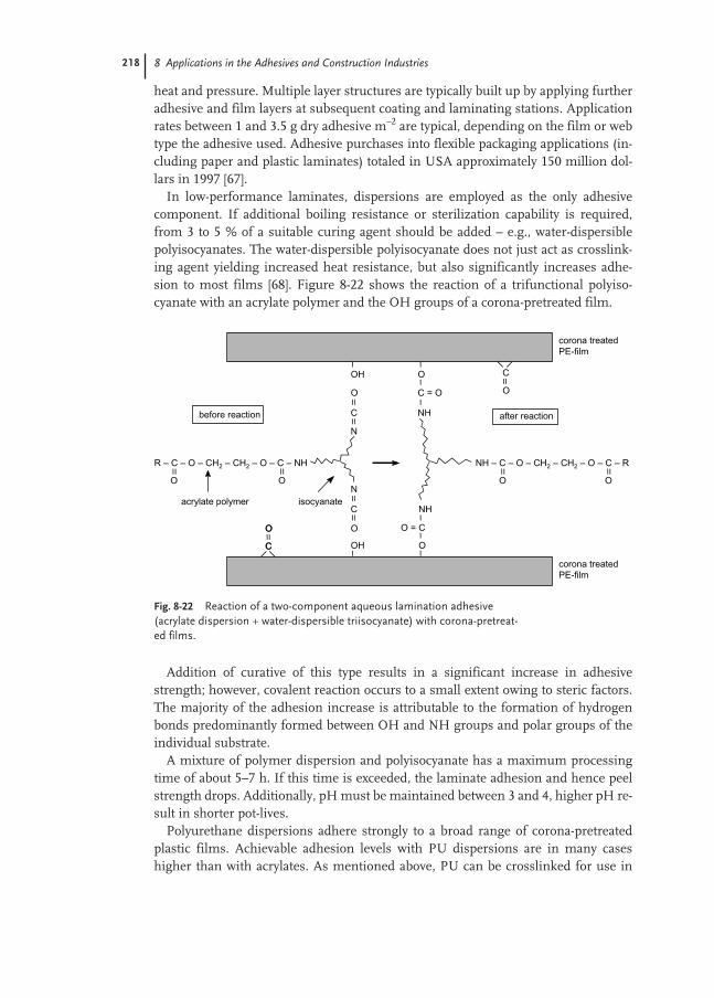
218 8 Applications in the Adhesives and Construction Industries
heat and pressure. Multiple layer structures are typically built up by applying furtheradhesive and film layers at subsequent coating and laminating stations. Applicationrates between 1 and 3.5 g dry adhesive m–2 are typical, depending on the film or webtype the adhesive used. Adhesive purchases into flexible packaging applications (in-cluding paper and plastic laminates) totaled in USA approximately 150 million dol-lars in 1997 [67].
In low-performance laminates, dispersions are employed as the only adhesivecomponent. If additional boiling resistance or sterilization capability is required,from 3 to 5 % of a suitable curing agent should be added – e.g., water-dispersiblepolyisocyanates. The water-dispersible polyisocyanate does not just act as crosslink-ing agent yielding increased heat resistance, but also significantly increases adhe-sion to most films [68]. Figure 8-22 shows the reaction of a trifunctional polyiso-cyanate with an acrylate polymer and the OH groups of a corona-pretreated film.
Addition of curative of this type results in a significant increase in adhesivestrength; however, covalent reaction occurs to a small extent owing to steric factors.The majority of the adhesion increase is attributable to the formation of hydrogenbonds predominantly formed between OH and NH groups and polar groups of theindividual substrate.
A mixture of polymer dispersion and polyisocyanate has a maximum processingtime of about 5–7 h. If this time is exceeded, the laminate adhesion and hence peelstrength drops. Additionally, pH must be maintained between 3 and 4, higher pH re-sult in shorter pot-lives.
Polyurethane dispersions adhere strongly to a broad range of corona-pretreatedplastic films. Achievable adhesion levels with PU dispersions are in many caseshigher than with acrylates. As mentioned above, PU can be crosslinked for use in
Fig. 8-22 Reaction of a two-component aqueous lamination adhesive(acrylate dispersion + water-dispersible triisocyanate) with corona-pretreat-ed films.

8.3 Laminating Adhesives 219
higher-end applications, or used alone to produce medium-performance laminates.In either case, low initial “green-strengths” after forming the laminate bond are com-mon. Moreover, it can take as many as seven days to achieve final laminate peelstrengths (by chemical reaction of isocyanates with hydroxyl groups), making it nec-essary to store laminate rolls temporarily prior to downstream converting.
A specially designed high performance acrylic dispersion that does not require ad-dition of crosslinking agent and which yields excellent green strengths has been de-veloped [69]. Due to the rapid development of peel strengths, laminates can be usedimmediately after production – thus, eliminating the need for inventory storage.Moreover, adhesive pot-life issues are eliminated because of the absence of a reactivesecond component.
Guiding formulationTwo-component polyurethane laminating adhesive
Wet partsDispersion Polyurethane dispersion (40 %) anionically
stabilized 100Crosslinking agent Water-dispersible, aliphatic
polyisocyanate, NCO content approximately 18 % 3–5
Test methodsWith film laminates made by adhesive bonding, the aim is to form the strongest pos-sible laminate, thus, peel strength (i.e. laminate adhesion) is typically measured. Thetest is usually carried out with 15 mm wide test strips where the film layers arepeeled apart using a tensile tester. The peel strength is specified in N/15 mm. Thetest report should furthermore indicate the failure mode; possibilities include filmtear, cohesive failure, and adhesive failure to either of the film surfaces involved (in-cluding printed layers). The peel strength in the region of a heat-sealed seam isknown as the seal seam strength.
8.3.2
Glossy Film Lamination
Glossy film lamination involves the covering of printed paper or board products withan optically clear, high-gloss plastic film. The process improves the brightness of theprinting inks and protects the printed material from external influences (e.g. scratch-ing, bleaching and moisture). Examples include book covers, advertising and pack-aging materials. Other methods besides film lamination are used to “finish” printproducts, including both physically and chemically cured coating systems. Glossyfilm lamination is used to a large extent in Europe but in North America, a specialform of film lamination, predominates, called “thermo-lamination” [70]. In thermo-lamination, oriented polypropylene (OPP) films with a pre-applied heat-sealable ad-hesive layer are thermally bonded to the substrate, therefore, eliminating the needfor additional adhesive.

220 8 Applications in the Adhesives and Construction Industries
High-gloss film laminates have been available in Europe since the 1960s. Lamina-tion is frequently still carried out using solvent-containing adhesives. Embossablepaper board laminates were only made possible by high adhesion, two-part solvent-containing polyurethanes with crosslinking agents. However, the limited pot lives oftwo-component systems require increased care from the processor.
Efforts to eliminate solvents to comply with more stringent emission regulationslikewise here resulted in the use of aqueous polymer dispersions. One-component,self-crosslinking dispersions with shelf lives equal to those of standard polymer dis-persions were developed, solving the pot life problem.
Wetting and flow of the adhesive on the film are the main prerequisites for highclarity lamination. This requires the polymer dispersion adhesive layer to be as plas-tic and film-forming as possible during the lamination process. However, such ad-hesive films would then be too soft and would result in partial separation betweenfilm and board during subsequent bending and embossing operations. A consider-able advance was made, however, with the development of aqueous acrylate-basedpolymer dispersions which crosslink after evaporation of the water, after the film hasformed. Crosslinking takes place at room temperature using a reactive ketone-dihy-drazide chemistry designed into the polymer dispersion (Fig. 8-23).
The polymer particles contain co-polymerized carbonyl groups which, on film for-mation, react with hydrazide groups of the water-soluble acid dihydrazide to formhydrazone. Increased cohesion strength results due to both inter-particle and intra-particle crosslinking reactions. A similar process also occurs between corona-pre-treated polypropylene film and the emulsion adhesive thereby significantly increas-
Fig. 8-23 Chemical crosslinking reaction of a one-component acrylic adhesive.

8.3 Laminating Adhesives 221
ing the adhesion strength of the laminate. As shown in the IR spectra for the PE filmsin Fig. 8-24, additional carbonyl and carboxyl groups are observed on the film surfaceafter pretreatment [71], which can then react with the dihydrazide crosslinking agent.
The measurement of peel strengths after drying shows that significant crosslink-ing occurs after only approximately 2 h and is complete after about 48 h. In practice,this means that bending and embossing of freshly produced board laminates shouldonly be carried out after this time period, in order to maintain film-to-film bond-ing [72].
Test methods
DryingThe progress of crosslinking over time can be recorded by measuring the surfacetack. This can be carried out using the Zosel tack measurement tester described inSect. 8.2.3 (Fig. 8-18). This enables measurement of the separation work of adhesivelayers throughout the course of drying.
Resistance to DelaminationAfter allowing sufficient crosslinking time, the lamination is formed, embossed andevaluated after certain time intervals. Formed and embossed laminates are classifiedas “failures” if the film is observed to have delaminated in the high-stress zones, asevidenced by pale strips or spots in the otherwise high-gloss, if possible dark, lami-nation.
Fig. 8-24 Infraredspectrum of polyethyl-ene films, according to W.-D. Domke andH. Steinke [71].
0,8
0,6
0,4
0,21900 1800 1700 1600 1500
wave number in cm-1
COOH
C = O
corona treated PE film
unteated PE film(according to W.-D. Domke u. H. Steinke)
absorption
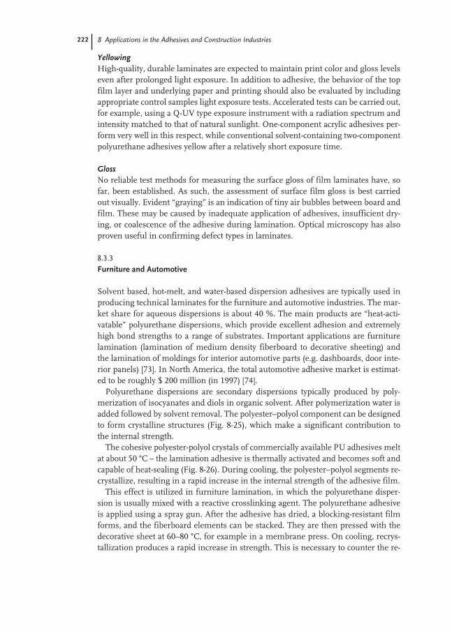
222 8 Applications in the Adhesives and Construction Industries
YellowingHigh-quality, durable laminates are expected to maintain print color and gloss levelseven after prolonged light exposure. In addition to adhesive, the behavior of the topfilm layer and underlying paper and printing should also be evaluated by includingappropriate control samples light exposure tests. Accelerated tests can be carried out,for example, using a Q-UV type exposure instrument with a radiation spectrum andintensity matched to that of natural sunlight. One-component acrylic adhesives per-form very well in this respect, while conventional solvent-containing two-componentpolyurethane adhesives yellow after a relatively short exposure time.
GlossNo reliable test methods for measuring the surface gloss of film laminates have, sofar, been established. As such, the assessment of surface film gloss is best carriedout visually. Evident “graying” is an indication of tiny air bubbles between board andfilm. These may be caused by inadequate application of adhesives, insufficient dry-ing, or coalescence of the adhesive during lamination. Optical microscopy has alsoproven useful in confirming defect types in laminates.
8.3.3
Furniture and Automotive
Solvent based, hot-melt, and water-based dispersion adhesives are typically used inproducing technical laminates for the furniture and automotive industries. The mar-ket share for aqueous dispersions is about 40 %. The main products are “heat-acti-vatable” polyurethane dispersions, which provide excellent adhesion and extremelyhigh bond strengths to a range of substrates. Important applications are furniturelamination (lamination of medium density fiberboard to decorative sheeting) andthe lamination of moldings for interior automotive parts (e.g. dashboards, door inte-rior panels) [73]. In North America, the total automotive adhesive market is estimat-ed to be roughly $ 200 million (in 1997) [74].
Polyurethane dispersions are secondary dispersions typically produced by poly-merization of isocyanates and diols in organic solvent. After polymerization water isadded followed by solvent removal. The polyester–polyol component can be designedto form crystalline structures (Fig. 8-25), which make a significant contribution tothe internal strength.
The cohesive polyester-polyol crystals of commercially available PU adhesives meltat about 50 °C – the lamination adhesive is thermally activated and becomes soft andcapable of heat-sealing (Fig. 8-26). During cooling, the polyester–polyol segments re-crystallize, resulting in a rapid increase in the internal strength of the adhesive film.
This effect is utilized in furniture lamination, in which the polyurethane disper-sion is usually mixed with a reactive crosslinking agent. The polyurethane adhesiveis applied using a spray gun. After the adhesive has dried, a blocking-resistant filmforms, and the fiberboard elements can be stacked. They are then pressed with thedecorative sheet at 60–80 °C, for example in a membrane press. On cooling, recrys-tallization produces a rapid increase in strength. This is necessary to counter the re-
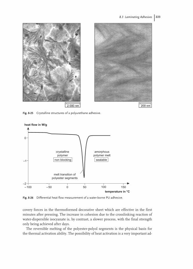
8.3 Laminating Adhesives 223
covery forces in the thermoformed decorative sheet which are effective in the firstminutes after pressing. The increase in cohesion due to the crosslinking reaction ofwater-dispersible isocyanate is, by contrast, a slower process, with the final strengthonly being achieved after days.
The reversible melting of the polyester-polyol segments is the physical basis forthe thermal activation ability. The possibility of heat activation is a very important ad-
Fig. 8-25 Crystalline structures of a polyurethane adhesive.
Fig. 8-26 Differential heat flow measurement of a water-borne PU adhesive.

224 8 Applications in the Adhesives and Construction Industries
vantage of polyurethane adhesives. It is also an example of switchable properties ofpolymers, where heat is the switch.
Formulation modificationsThe addition of suitable resin dispersions and small amounts of plasticizer enablesthe thermal activation temperature to be reduced, although this also results in a re-duction in heat resistance. In contrast, the addition of crosslinking agents improvesadhesion and water resistance and increases the heat resistance. The crosslinkingagents used are water-dispersible triisocyanates, carbodiimides and polyaziridines.The reactivity of the crosslinking agents is reduced by various methods so that an ad-equate processing time is available. Mixing with other acrylic dispersions allows theproperties to be modified and the costs of the adhesive to be reduced.
Guiding formulationTwo-component polyurethane dispersion for furniture lamination
Wet partsDispersion Luphen D 200 A, 40 %,* or Dispercoll U 53§ 100Crosslinking agent Water-dispersible polyisocyanate 5
Suppliers: *BASF AG, Ludwigshafen, Germany; §Bayer AG, Leverkusen, Germany
Test methodsThe static peel strength of the laminate made from PVC furniture sheet and MDF isassessed visually for delamination after storage at elevated temperature.
8.4
Construction adhesives
8.4.1
Floor-covering Adhesives
The term floor-covering adhesives denotes all materials for laying flexible floor-cov-erings. These include secondary and unitary backed carpets, felt backed vinyl, vinylcomposition tile (VCT), homogeneous vinyl sheet, rubber, and various vinyl andpolyurethane backed carpet tile products. Rigid coverings, such as natural stone, ce-ramic and parquet, are not included here.
The main driving force for the development of modern floor-covering adhesives isthe need for reduced volatile organic content (VOC). Though there are regional dif-ferences, reducing emissions of organic solvents is a worldwide consumer driventrend based on environmental and health concerns (sick building syndrome).
In Europe at the beginning of the 1960s, flexible floor-coverings (such as linoleum)were bonded using alcohol-soluble resin adhesives. However, these were unsuitablefor the new PVC floor-coverings on the market, for which solvent-containing poly-chloroprene adhesives consisting of 75 % of organic solvents and 25 % of poly-chloroprene and resins were used. These contact adhesives had to be applied to both

8.4 Construction adhesives 225
sides, i.e. to the back of the floor-covering and to the floor. A precise laying techniquewas vital as the floor-coverings, which were laid after the solvent had evaporated,could not be corrected once laid. This technique was soon also used for bondinghigh-quality carpeting.
A severe disadvantage of contact adhesives with a solvent content of 50 to 70 % wasthe emission of large amounts of solvents. Poor ventilation and the presence of anignition source resulted in explosions, burns and even fatalities.
The first polyacrylate dispersion for the production of aqueous floor-covering ad-hesives became available in Europe in the mid 1960s. The adhesive consisted of40 parts of Acronal 80 D (50 %), 40 parts of chalk and – to improve the wet tack –20 parts of balsam resin solution (70 % in toluene). The solvent content was only6 %, and the bond strengths which could be achieved for PVC floor-coverings corre-sponded to the level of polychloroprene contact adhesives. In addition to significant-ly reducing the risk of accident, further advantages of the new type of adhesive were:– application of adhesive to one side only– the floor-coverings could be corrected– good aging resistance– fresh adhesive residues could be removed from the floor-covering and tools using
waterSolvent based polychloroprene adhesives have a different setting mechanism
compared to water based flooring adhesives. Polychloroprene adhesives developtheir bond strength through recrystallization of the elastomer from solution. In thecase of emulsion adhesives, the polymer particles are initially swollen by the resinsolution. During evaporation of the water, a film-formation phase occurs in whichthe polymer film, due to the residual solvent, has particularly high tack and lowcohesion. The final strength is then achieved by two processes occurring in parallel:
Firstly, post-flow of the polymers on to the substrate surfaces results in an in-creased contact area and consequently in an increase in adhesive strength; secondly,evaporation of the residual solvent and recrystallization of the small and rigid abieticacid molecules increase the cohesion of the polymer film to its final strength.
At the beginning of the 1970s, rapid growth commenced for back-coated textilefloor-coverings, which were also bonded using one-side adhesives. At the end of the1980s, solvent-free floor-covering adhesives were produced for the first time withAcronal A 323 in combination with a plasticizer. In these, the tackifying resin solu-tion was replaced by a resin melt. Adhesives formulated in this way have proven ad-hesive properties and are solvent-free substitutes as defined in the Technical Rulesfor Hazardous Materials, TRGS 610 [75].
The next generation of floor-covering adhesives was developed in 1994. In these,solvents, plasticizers and resins were deliberately omitted. Although plasticizers arenot solvents in the sense of TRGS 610, they are nevertheless low-molecular-weightsubstances with a certain vapor pressure and are consequently a source of emissions.Resins were omitted because the usual abietic acid derivatives are odor carriers. Theabsence of the action of these two proven starting materials was compensated by alarger proportion of the softer and tackier acrylate dispersion Acronal A 200 or Pri-mal CA-187 (see guide formulation 2) [76].
226 8 Applications in the Adhesives and Construction Industries
The adhesive formulated in this way has very low emissions as defined in the re-quirements published by the Association of Emission-Controlled Laying Materials(Gemeinschaft Emissionskontrollierter Verlegewerkstoffe, founded in Germany) atthe beginning of 1997. These requirements have no legal foundation, but are basedon a voluntary self-commitment by the member companies for processor and con-sumer protection. The emissions are measured using a chamber test method (seeTest Methods), which enables firstly, volatile carcinogenic (suspected or proven) con-stituents to be identified and measured after 24 h (processor protection) and second-ly, the long-term total emissions of volatile organic compounds (TVOC) to be deter-mined after 240 h (consumer protection). Corresponding to the TVOC after 240 h,three emission classes are defined: EC 1 very low emissions (TVOC <500 µg m–3),EC 2 low emissions (500 to 1500 µg m–3) and EC 3 not low emissions (TVOC>1500 µg m–3). For all classes the maximum emission of carcinogenic compoundsafter 24 hours has to be less than 10 µg m–3.
In North America reductions in solvent levels in floor-covering adhesives havebeen essentially driven by environmental and VOC concerns. In March 2001, theCalifornia South Coast Air Quality Management District (SCAQMD) approved a pro-posal, Rule 1168, to reduce solvent levels, specifically non-exempt VOC, in floor-cov-ering adhesives from approximately 150–200 g L–1 to approximately 50–70 g L–1. Oth-er state agencies are expected to implement similar solvent and VOC criteria in yearsto come. These regulatory changes necessitate a further shift from solvent-rich adhe-sive systems towards water-based adhesive technology.
Total North American carpet consumption in 1999 was approximately 1.6 billionsquare meters, split between two main sectors, residential (75 %) and commercial(25 %). Residential carpets are typically installed using glue-less installation tech-niques (e.g. tack-strip). However, carpets in commercial installations includingschools, retail establishments, hospitals, workplaces and hospitality facilities are in-stalled employing specially designed or multipurpose adhesive systems. These adhe-sives are typically formulated employing non-carboxylated, high-solids, styrene-buta-diene lattices (SBR HSL), hydrocarbon resin-oil blends, and fillers as the primarycomponents. In the past, such adhesives were formulated with resin solutions basedon hydrocarbon solvents (e.g. mineral spirits) and/or plasticizers. Environmentalpressures led to near elimination of solvents and plasticizers in the 1990s and intro-duction of increasingly lower VOC adhesives made with increasingly higher viscosi-ty “naphthenic” oils.
Flooring mastics based on non-carboxylated SBR HSL are employed primarily incarpet and mineral fiber or felt-backed vinyl glue-down applications over most com-mon sub-floor surfaces. Such SBR based adhesives are not recommended for “un-backed” vinyl (PVC) applications due to plasticizer migration from PVC to the adhe-sive and bond loss issues. Conventional “felt” backings provide an effective barrier toplasticizer migration. In contrast, acrylic copolymer based floor-covering adhesives areemployed in direct vinyl contact applications where plasticizer resistance is required.
The main constituents of the SBR HSL based flooring adhesive are the resin–oilblend, surfactant, latex and filler (see guiding formulation 1). Carefully selectedresin–oil systems are employed for both cost and property reasons (early wet tack

8.4 Construction adhesives 227
development, legging or webbing, initial or “green” strength, final bond strength,aging resistance and low VOC). Webbing and bond strength are also sensitive to for-mulation latex content, typically in the order of 10–15 %. The rosin acid and non-ion-ic surfactants in this formulation serve to stabilize the oil in water emulsion duringcompounding and to provide end-product in-can stability. Urea can be employed toachieve freeze-thaw resistance (low molecular weight alcohols and/or glycols canalso be considered). Caustic solution (e.g. 20 % KOH) is added to neutralize the rosinacid and to achieve sufficiently high pH so that when the non-carboxylated HSL isadded, pH shocking effects with coagulation are avoided. Clay is added for reinforce-ment purposes and for cost–performance optimization. Alkali sensitive emulsions(e.g. Latekoll D) are added for thickening purposes.
The key parameters to control are formulation water content, clay/latex ratio andresin/latex ratio, depending on the desired adhesive cost structure. Not surprisingly,too much filler or too little resin and/or oil will result in inferior properties. Excesswater will result in slower drying, and probably the need for more “water sensitive”thickeners. Like many other SBR based adhesives, HSL based flooring mastics in-clude in-can and dry-film preservatives as well as an antioxidant package to ensurelong-term performance.
The total volatile organic content (TVOC) is a key property of floor-covering adhe-sives. In the mid 1990s, the Carpet and Rug Institute (CRI) introduced a voluntaryTVOC specification for floor-covering adhesives, defined as the Green Label Pro-gram in North America. The method employs a small chamber test apparatusdescribed in ASTM D-5116. For CRI Green Label certification, 24-h emission ratesfrom adhesives must be <10 mg m–2 h–1 for TVOC, <3 mg m–2 h–1 of 2-ethylhexylalcohol, and <0.05 mg m–2 h–1 for formaldehyde. TVOC and formaldehyde arequantitated employing thermal desorption GC–MS and HPLC techniques, respec-tively.
In North America, formulation technology based on high solids content styrenebutadiene lattices and naphthenic oils are widely used in the market place. LowTVOC products have evolved to meet the CRI Green Label requirements and to pro-vide cost-effective, high performance adhesives for carpet and felt-back vinyl floor-coverings.
Floor-covering adhesives made from water-based polymer emulsions contain ap-proximately 10–20 % dry polymer in both European and North American systems.Floor-coverings are bonded using an application rate of about 250–500 g m–2.
Guiding formulations1. High solids content styrene butadiene (HSL) and naphthenic oil based flooring
adhesive for carpet and felt backed vinyl floor-coverings with emissions satisfyingCRI Green Label TVOC requirements. Such adhesives are not recommended forhomogeneous or solid vinyl sheet goods where plasticizer migration is a concern.

228 8 Applications in the Adhesives and Construction Industries
Wet partsHydrocarbon resin Neville LX 1200* 9.7Rosin acid Melhi 2.2Naphthenic oil Tufflo 1200‡ 12.0Surfactant Igepal CO-897 (70 %)§ 0.2Surfactant Igepal CO-530 0.1Anti freeze Urea (50 %) 1.4Neutralizing agent Potassium hydroxide (2.5 %) 8.7Filler Huber 95 (70 % clay slurry)# 41.4HSL dispersion Butonal NS 104 (71 % s.c.)** 20.4Thickener Latekoll D (pH adjusted 8 % solution)** 3.9Total 100
Procedure: Add resins to oil at 140–150 °C, stir until homogeneous, then cool to95–98 °C. Surfactant, urea and KOH solution are slowly added under mild agitationto form an emulsion. The clay, SBR, and thickener are then added to the resin emul-sion in the order indicated above.2. Very low emissions corresponding to the requirements of the German association
of Emission-Controlled Laying Materials (GEV)Wet parts
Dispersion Acrylic dispersion 24.4Plastiziser Plastilit 3431** 2.0Antifoam Agitan 282†† 0.2Dispersant Pigment dispersant NL** 0.5Chalk Ulmer white XM‡‡ 42.0Thickener Latekoll D 2 %** 10.9Resin melt Gum resin WW: Plastilit 3431 = 8:2 16.0Resin Poli melt 15§§ 4.0Total 100
Suppliers: *Neville Chemical Company, Pittsburgh, PA, USA; †Hercules Incorporated, Wilmington,DE, USA; ‡Lyondell Lubricants, Houston, TX, USA; §Rhone-Poulenc, Cranbury, NJ, USA;#J.M. Huber Corp., Wrens, GA, USA; **BASF, Charlotte, NC, USA; Ludwigshafen, Germany; ††Münzing Chemie, Heilbronn, Germany; ‡‡Omya, Cologne, Germany; §§Erbsloeh, Krefeld, Germany
Test methodsNorth American industry standard test methods for floor-covering adhesives are cur-rently not available. However, methods are under development by ASTM committeeD14.70.12, Carpet Adhesives. As a guiding method for evaluating carpet to plywoodpeel strength the adhesive is troweled on to plywood (application weight ca.300 g m–2), after 20 min the carpet or vinyl is laid and pressed down at room temper-ature, and, after a certain curing time at room temperature or 60 °C, the floor-cover-ing is peeled off at 90° angle using a tensile tester.
Drafts of European test standards for measuring peel and shear strengths of floorand wall coverings were submitted for approvals in early 1999 by Technical Commit-tee CEN/TC193. These methods, referred to as prEN 1372 and prEN 1373 respec-tively, are fundamentally quite similar to methods developed in Germany through a

8.4 Construction adhesives 229
collaboration between floor-covering manufacturers, official test institutes, and ad-hesive and raw material producers. German test standards and specifications forpeel and shear strength discussed below are summarized in DIN 16860 for PVCfloor-coverings and in DIN 53269 for textile floor-coverings.
Peel resistanceThe peel resistance is the force, per unit width of floor-covering, which results whenpeeling-off a bonded sample perpendicular to the original adhesive bond line. Ac-cording to regional requirements, the adhesive is applied to plywood, cement boardor other substrate using a trowel spreader and, after a certain “open” or evaporationtime, a 5 cm × 30 cm floor-covering strip is laid on to the adhesive bed and presseddown, preferably using a fixed weight roller (e.g. 5 kg). After a storage time under de-fined standard laboratory conditions, the floor-covering strip is peeled perpendicularto the adhesive join at a certain speed using a tensile testing machine (Fig. 8.27). Thepeel forces which occur during this operation are measured and specified inN mm–1. According to DIN 16860, the average peel strength must have a certainminimum value (e.g. 1 N mm–1). Other factors such as early bond strength develop-ment, water resistance, and accelerated oven aging (e.g. 50 °C) can also be evaluatedusing variations of this general method.
Shear strengthThe shear strength is the force per unit area which results in fracture of bonded sam-ples parallel to the bond joint. Adhesive areas of 1000 mm2 (ca. 2.5 cm × 5 cm) areproduced on plywood or other cementitious substrates using a template and trowel,then the floor-covering is laid on to the adhesive area and pressed down. After a stor-age time under standard laboratory conditions, the floor-covering is removed parallelto the adhesive join at a defined speed using a tensile testing machine. The shear
Fig. 8-27 Measurement of peel resistance.

230 8 Applications in the Adhesives and Construction Industries
forces which occur during this operation are measured and specified in N mm–2 .According to DIN 16860, the mean of the shear strength must have a certain mini-mum value (e.g. 0.3 N mm–2) to be considered “passing”.
The curing of water-based adhesives is typically dependent on temperature andhumidity conditions. For this reason, it has proven useful in the development of wa-ter-based adhesives for carpets and other floor-coverings to also test peel strength asa function of time. There are two additional test methods for this:
Green strength developmentThe 5 cm wide floor-covering strip is laid in the wet emulsion adhesive after a10–20 min drying time, and then pressed down. Floor-covering specimens arepeeled off at a certain speed perpendicular to the adhesive join after a further 10, 20,30, and 60 min. The peel forces, which occur during this operation are measured andspecified in N/5 cm strip. Depending on drying conditions and adhesive composi-tion, peel strengths on the order of 10–15N/5 cm strip should be expected within15–30 min after applying the floor-covering strip. When peel testing SBR HSL basedmastics in particular, it is equally important to also report the degree of web or legdevelopment as a function of time. While not necessarily correlated with final adhe-sive bond strength, installers nevertheless commonly look for early web develop-ment as an indication of adhesive quality.
Open timeOpen time represents the maximum recommended time after troweling that thefloor-covering should be laid into the adhesive. To quantify this parameter, a 5 cmwide floor-covering specimen is placed in the partially dried emulsion adhesive after30, 45, 60 and 90 min airing times and pressed down. The floor-covering is immedi-ately peeled off at a certain speed perpendicular to the adhesive join. The peel forces,which occur during this operation are measured and specified in N/5 cm. After ex-ceeding the open time, unacceptably low peel strengths and poor adhesive grab on tothe floor-covering substrate are observed. As with green strength development, tem-perature and humidity conditions also have a significant impact on the open time ac-tually found under installation conditions. Typically, longer open times and delayedgreen strength development are expected at higher humidity and lower installationtemperatures (i.e. because of slower water evaporation from the adhesive itself).These two methods have a reproducibility of ±20 %.
Chamber method for emission measurementNorth American “CRI Green Label” and European chamber TVOC methods forflooring adhesives are fundamentally similar. In both cases, the adhesive sample isapplied to a stainless steel or glass plate and immediately sealed in a stainless-steeltest chamber carefully maintained under well defined temperature and humidityconditions (e.g. 23 °C, 50 % rel. humidity). VOC are collected onto adsorption tubescontaining suitable adsorbents after flowing purified air through the chamber at acontrolled rate. The CRI Green Label method requires volatile and formaldehydesamples be collected at the 24 h point. However, the German Association of Emis-
8.4 Construction adhesives 231
sion-Controlled Laying Materials specifies that substances known or suspected ofbeing carcinogenic must be determined at the 24 h point (in accordance withHazardous Materials Regulation/TRGS 905), but also that long-term emissions bedetermined after 10 days. After desorption, the emitted substances are determinedby gas chromatography (GC-MS coupling) or liquid chromatography. The long termemissions are quantified using toluene as standard substance for volatile substancesin low concentration. Loading of the chamber should be at 0.4 m2 m–3 and the airexchange rate at 0.5 chamber volumes per hour (1.0 air exchanges per hour in theASTM protocol).
8.4.2
Sub-floor and Wall Mastics
Sub-floor and wall mastics are employed in a host of building and home construc-tion applications. Sub-floor type mastics are typically used for fixing plywood sub-flooring to lumber floor joists and more recently applied to secure plywood roofsheathing to roof rafters and trusses of existing roofs. In both of these applications,nails are also used to hold the plywood in place, but the adhesive greatly augmentsthe structural strength. For example, in wind exposure tests [77], adhesives werefound to increase resistance to wind uplift forces by factors of 2–3 compared to tradi-tional nail down methods, important for homes and buildings in areas prone to tor-nadoes and hurricanes. Plywood-lumber sub-floor mastics are employed in qualityconstruction systems to eliminate nail pops and floor squeaking. Improved masticsystems are required which are compatible with commercial oriented strand boards(OSB) used increasingly in place of standard plywood in both sub-floor and roofingconstructions.
Sub-floor mastics are generally supplied in cartridge form (310 cm3 and 860 cm3
tubes) and applied as a 6 mm bead using standard caulk gun applicators. Overallmarket in North America for this class of adhesive is approximately $35 millionyear–1 with 3 % growth per annum. The market consists predominately of formulat-ed solvent based styrene–butadiene polymers, moisture-cure polyurethanes, andhigh performance water based acrylic systems. Increasing VOC concerns coupledwith lower solvent threshold limits in California [78] are driving the eventual move-ment to environmentally friendly, low VOC water-based mastics.
An estimated 75 % of the mastic products sold in North America indicate compli-ance to stringent AFG-01 (i.e. “Adhesives for Field Gluing”) requirements. ASTM D3498 is quite similar to the AFG-01 standard originally written by the American Ply-wood Association. These methods define a series of six test specifications (Fig. 8-28),five of which involve shearing plywood to lumber wood block specimens in com-pression mode after various carefully controlled material conditioning and specimencuring protocols (Fig. 8-29).
The sixth test, called oxidation resistance, is a mandrel flexibility check on films ofdried mastic after exposure to oxygen at high temperature in an oxygen bomb appa-ratus. Water based mastics formulated with acrylics or styrene-acrylic polymer dis-persions typically pass oxidation resistance requirements. The most challenging pa-

232 8 Applications in the Adhesives and Construction Industries
rameters to balance, however, involve moisture resistance and frozen lumber.Frozen lumber adhesion is promoted through the use a combination of coalescentsand freeze-thaw aids (e.g. glycols, alcohols). Levels of such additives are kept to aminimum in order maintain maximum resistance to moisture.
The wall mastic market in North America is roughly twice the size of the sub-floormarket mentioned above. Typical wall mastic applications include:– wood bonding to concrete walls and floors– bonding drywall or gypsum board and paneling to studs and framing structures
Fig. 8-29 Performance specifications for Adhesives for Field Gluing Plywood towood framing (AFG-01) rh relative humidity, o.v. over night, 1 N = 0.2248 lbf.
Conditioning Assembly curing Test specificationsof materials
Dry lumber 48 h, 37 °C/30 % rh 28 days, 37 °C/30 % rh Shear >1000 NWet lumber 48 h soak lumber; 28 days, 37 °C/90 % rh Shear >1000 N
48 h, 37 °C/90 rh for Plywood
Frozen lumber 48 h soak lumber 5 days, –14 °C Shear >667 N48 h; –14 °C for lumber 21 days, 4 °C/50 % rh and plywood 7 days recovery
Moisture 48 h, standard 28 days, 22 °C/50 % rh Shear >1000 N; resistance conditions 3 cycles of 4 h H2O/o.n. <10 % bond failure
dry 37 °C 7 day recovery
Gap filling 48 h, standard 28 days, 22 °C/50 % rh Shear >667 Nconditions (16 gauge wire)
Oxidation 3 days, 22 °C/50 % rh; bend over 6 mm resistance 2 days, 48 °C/50 % rh; Mandrel: no cracking
500 h, 70 °C/20bar O2
Fig. 8-28 Plywood on lumber shear test (AFG-01).
Plywood
Lumber
Force
AdhesiveBond Line

8.4 Construction adhesives 233
In concrete bonding applications, use of adhesives eliminate the need for timeconsuming drilling operations and prevents damage to the concrete substrate. Drywalladhesives are used increasingly as builders look for ways to replace time consuminghammer and nail approaches [79]. Test specifications for drywall adhesives are de-scribed in ASTM C-557, Adhesives for Fastening Gypsum Wallboard to Wood Framing.
Like sub-floor mastics, wall mastics are also manufactured in solvent based,polyurethane and water based formulations. Due to reduced strength requirements(i.e. relatively low inherent strength of drywall), drywall mastics are typically filled toa higher degree and thus, are less costly compared to AFG-01 sub-floor mastics.
Guiding formulationSolvent-free plywood-lumber sub-floor adhesive
Wet partsDispersion Acronal DS 2159* 56.7Dispersant Pigment disperser N* 0.1Dispersant Sodium tripolyphosphate 0.1Defoamer Nopco NXZ† 0.05Tackifier Snowtack 301 A‡ 3.6Anti freeze Ethylene glycol 3.0Coalescent Eastman DBA§ 2.3Filler Duramite†† 11.4Filler Clay†† 22.7Thickener Latekoll D* 0.3Total 100
Ingredients are combined in the order indicated above at room temperature withhigh-speed agitation.Adhesive properties: 70 % solids content, pH 9, 40 % polymer on dryAFG-01 testing: Moisture resistance: 3100 N (>1000 N required)
Frozen lumber: 880 N (>667 N required)Bond failure: None (<10 % required)
Suppliers: *BASF Corporation, Charlotte, NC, USA; †Henkel, Ambler, PA, USA; ‡Akzo Nobel, Woodstock, CT, USA; §Eastman Chemical Company, Kingsport, TN, USA; ††ECC Interna-tional, Atlanta, GA, USA
8.4.3
Sealants
Sealants or caulks in accordance with ISO 6927 are materials which remain plastic orelastic and are used for sealing a joint between two separate construction parts, thus,eliminating passage of the “elements” through the joint (i.e. hot or cold air, mois-ture, insects). While a caulk needs only fulfill the above general purpose, sealants areconsidered higher end products that must additionally perform after repeated exten-sion-compression cycles originating from material temperature and humidity fluctu-ations. Historically, the starting point for sealants was the natural raw material lin-seed oil, mixed with chalk to give window putty.
234 8 Applications in the Adhesives and Construction Industries
Synthetic polymers suitable as binders for the production of caulks and sealantsinclude silicones, polyurethanes, polysulfides, and aqueous polymer emulsions. Theimportance of these sealants in the construction industry has also increased consid-erably through the increased use of prefabricated elements. The movement of com-ponents must be absorbed and compensated by the joint sealant. These movementscan be expansion, contraction, or shear.
While silicones, polyurethanes and polysulfides set through a chemical reaction,water based emulsion sealants achieve their functional end state by simple physicaldrying, i.e. evaporation of the water. The majority of emulsion sealants are com-posed of acrylic emulsions and to a lesser extent vinylacrylic and other copolymers.
Polymer emulsion sealants can be used on all sorptive substrates, such as con-crete, aerated concrete, cement panels, plaster and wood. They are used for sealingall types of internal joints, connecting joints (internal and external) and expansionjoints (internal and external) with a movement capability of 10–15 %. In Europe, thejoint design is stipulated in the relevant standards, for example DIN 18540.
The total caulk and sealant market in North America is estimated 500 000 tons offormulated sealants [80], with acrylic emulsion sealants comprising approximately15 % of the total market, and 23 000 tons dry acrylic resin. Water based sealants, soldprimarily in cartridge tubes, are used predominately in construction applicationswhereas reactive urethanes and silicones are used in more demanding constructionand automotive applications.
Formulation ingredientsThe properties of an emulsion caulk or sealant are affected by the type of emulsion,and by the type and amount of the fillers and/or pigments, plasticizers and thicken-ers [81].
Fillers reinforce and increase the volume of the sealant. Fillers also reduce formu-lation costs and affect the technical properties of the sealant itself. Common fillersfor sealants are calcium carbonate (chalk), aluminum silicate (clay), barium sulfateand silicic acids. Finely divided fillers, such as talc and Microdol 1, reduce the sur-face tack while simultaneously stiffening the film. Thixotropic fillers, for examplefumed silica or SiO2, improve the gunnability and reduce the sag of the composi-tions. Pigments are used to color sealants; the white pigment used is usually titani-um dioxide.
Depending on the degree of compatibility, plasticizers and coalescents reduce the glass transition temperature of the polymeric component and thereby enhancelow-temperature flexibility and film elongation. While improving formulation cost,excessive plasticizer detrimentally affects film strength, tack and therefore, dirt pick-up resistance. For the production of polymer emulsion sealants, phthalates, diben-zoates, polyisobutenes and Plastilit 3060 have proven successful. With Plastilit 3060(propylene glycol alkylphenyl ether) as plasticizer, sealants with faster skin forma-tion after application and lower Shore hardness which are particularly elastic at lowtemperatures are obtained. Experimental testing to ensure long-term polymer-plasti-cizer compatibility and minimum tendency to volatilize or migrate to the exposedsurface is always recommended.
8.4 Construction adhesives 235
Dispersing aids and surfactants improve the incorporation of fillers and pigmentsand improve the sealants’ storage stability. In general, low molecular weight polycar-boxylic acid salts are used.
Silane-based coupling agents can be employed to improve adhesion to difficultsubstrates (e.g. glass, aluminum). A new class of hydrolysis resistant silanes are nowavailable [82] which minimize self-crosslinking reactions, improve storage stabilityand provide desired enhanced adhesion performance even after extended packageaging. Sealants containing small amounts of silane adhesion promoter are referredto as “siliconized”.
Anionic thickeners based on polycarboxylic acids, associative thickeners andfumed silica are used to adjust the rheological behavior of sealants. Highly dispersefumed silica with a average particle diameter of from 10 to 30 µm is used asthixotropic agent to ensure that the sealant flows out of the cartridge well even undergentle pressure, but has low sag after removal of the shear stress.
Addition of suitable antifreeze agents, for example ethylene glycol, protects thesealants against freezing during storage and transport.
Both “wet phase” biocides and “dry film” preservatives should also be added to thesealants produced using polymer dispersions in order to achieve adequate protectionagainst microbiological attack. The suitability of these preservatives must be estab-lished and monitored experimentally.
The mechanical properties of water-based sealants are essentially determined bythe ambient temperature and atmospheric humidity. Figure 8-30 shows the tensilestress of a sealant at 50 % elongation as a function of time under various climaticdrying conditions.
Sealant typesThree types of water-based sealant are commercially available; clear, translucent, andfilled sealants. The majority of the market (>75 %) consists of the filled variety. Clearand translucent sealants are used when a clear or translucent “look” is desired and inapplications requiring higher adhesion performance, elongation, and dried filmstrength. While fillers serve to reduce formulation cost and surface tack, thus, dirtpickup, they reduce adhesion performance and film elongation.
Clear and translucent sealants consist primarily of polymer dispersion (ca.75–95 % by weight) and various formulation auxiliaries such as plasticizers, de-foamers, preservatives, thickeners, and freeze-thaw agents. Since fillers are not used,formulation solids content is essentially defined by the solids content of the polymerdispersion used, which for currently available materials, is typically <65 %. Higherwater contents promote slower sealant drying rates. Relatively hard acrylic copoly-mers (Tg = –10 to +10 °C) are needed in clear sealants to minimize surface tack andsubsequent dirt pick-up. Translucent sealants are formulated similarly but withsmall amounts of fumed silica thickener to adjust flow properties.
Filled sealants are typically formulated with approximately 25–35 wet parts poly-mer dispersion per 100 parts total formula, with filler to binder ratios in the rangefrom 2 to 4. With high filler loads, formulation solids contents in the vicinity of 90 %are possible. Because of the “stiffening” effect of most fillers, filled sealants are pro-

236 8 Applications in the Adhesives and Construction Industries
duced either with lower Tg emulsion polymers (–40 to –30 °C) and low plasticizer lev-els or with higher Tg copolymers (<0 °C) and higher levels plasticizers which “soften”the dried sealant film.
Guiding formulations1. Filled sealant with good elasticity (even at low temperatures) and a broad adhesion
spectrumWet parts
Dispersion Acrylic dispersion, pH 8 with NaOH 20 % 31.5Plasticizer Plastilit 3060* 2Pigment paste Plastilit 3060/Kronos 2056 TiO2
† (1:1) 10Emulsifier Lumiten N-OG* 0.2Dispersant Pigment dispersant N* 0.1Filler, CaCO3 Omya BLP 3† 55.5Thixotropic agent Silicic acid HDK H 20‡ 0.7Total 100Sealant properties: filler/binder ratio = 2.71, solids content = 89 %Polymer dispersion properties: 65 % solids, Tg = –30 °C
Fig. 8-30 Tensile stress values of a dispersion sealant at 50 % elongationand various climatic influences, r.h. relative humidity.

8.4 Construction adhesives 237
2. High solids, rapid drying, low cost formulation for common gap filling applica-tions; paintable
Wet partsDispersion Acrylic dispersion 23.8Plasticizer Palatinol N, C-9 phthalate* 10Surfactant Emulphor OPS 25, non-ionic* 0.3Dispersant Pigment disperser N* 0.6Filler Mikrodol 1, CaCO3 61Sealant properties: filler/binder ratio = 4.3, solids content = 90 %Polymer dispersion properties: 60 % solids, Tg = –10 °C
Suppliers: *BASF Corporation, Charlotte, NC, USA; †Omya GmbH, 50968 Cologne, Germany; Tipure R901-01 TiO2 also available from Dupont Chemical, Wilmington, DE, USA; ‡Wacker-Chemie, 81737 Munich, Germany; Aerosil 200 fumed silica also available from Degussa Corporation, Ridgefield Park, NJ, USA.
Production of sealantsVacuum planetary mixers have proven particularly successful for the production ofwater-based polymer emulsion sealants.
The dispersion is adjusted to pH 8 using 20 % sodium hydroxide solution. Thick-ener and dispersant are then added, and the mixture is stirred briefly at low speed.The plasticizer is then added directly.
It has proven favorable in experiments to grind finely divided pigments (for exam-ple titanium white and iron oxide black) with the same amount of plasticizer in a rollmill and to incorporate the resultant pigment paste into the dispersion before thefillers. This suppresses the formation of pigment particle agglomerates, which canotherwise easily occur. After a stirring time of about 8 min at 30–40 rpm, the fillersare added in 3 or 4 portions; after each addition, the mixture is stirred for about5 min until smooth. The speed is then gradually increased to about 80 rpm. After thefinal addition of filler, the stirring arms are scraped and stirring is continued for afurther 5 min. The homogeneous mixture is then deaerated for about 5 min under avacuum of 900 mbar with stirring at 20 rpm and then packed into polyethylene orfoil carton cartridge tubes. A minimum shelf life of 6 months can be assumed inproperly sealed cartridges.
Test methodsResistance to flowThe resistance to flow is the property of a sealant to remain in the specified shapeafter processing. For testing, a U-profile is filled with sealant (EN 27390, DIN 52454,ISO 7390, ASTM D-2202).
Elastic recoveryElastic recovery is the magnitude of the recovery of a sealant after prior elongationfollowed by release. For the measurement, two concrete test specimens are joined to-gether, the joint is stretched by 50 %, and after 24 h the separation is measured afterrelease (EN 27389, DIN 52458, ISO 7389, ASTM C-736).

238 8 Applications in the Adhesives and Construction Industries
Adhesion-elongation testTwo concrete test specimens are joined together and pulled apart in a tensile testingmachine at 6 mm min–1 until the breaking point is reached (DIN 52455, EN 28340,ISO 8339, ASTM C-735).
The mechanical properties of a good emulsion-based sealant should be an elasticrecovery of 60–70 %, a tensile stress of 0.1–0.15 N mm–2 and an elongation at breakof 200–300 %.
In North America ASTM C-834 and C-920 are used. These are actually umbrellaspecifications constructed from a host of individual ASTM test methods [83]. In gen-eral, latex sealants are typically unsuitable for sealing joints which are constantly ex-posed to water or subjected to strong expansion movements. However, sealants canbe developed which satisfy the specifications defined in ASTM C-834 for “latex seal-ing compounds”. Higher performance “elastomeric joint sealants” based on sili-cone, polyurethane and advanced acrylic emulsion technologies are typically de-signed to satisfy the ASTM C-920 standard. ASTM C-920 class A sealants are thosethat can withstand deformations as high as 50 % while class B sealants tolerate de-formations as high as 25 %.
Notes for useWater-based sealants generally adhere sufficiently well to sorptive substrates withoutpre-coating. However, in order to achieve greater reliability, in particular to bind dustparticles, pre-coating of the joint edges with dilute sealant (for example 1 part ofsealant with 3 parts of water) has proven successful in practice.
The sealant is introduced into the joint using a manual or compressed-air caulkinggun. The surface is then smoothed using a wet flat brush.
Jointing should not be carried outside in the rain or at temperatures below +5 °Csince the dispersion is still water-sensitive after application. Depending on the tem-perature and relative atmospheric humidity, it requires 30–60 min to form a suffi-ciently thick skin on the surface. Tools should be cleaned with water immediatelyafter use as the residues can only be removed mechanically once they have dried.
8.4.4
Ceramic Tile Adhesives
In contrast to the traditional thick-bed method in which tiles are laid in thick layersof mortar, the thin-bed method involves adhesive bonding. This means that the tilesare laid into a wet adhesive bed trowel applied on to a substrate. The thickness of theadhesive bed is variable and depends both on the size of the tiles and on the natureof the tile undersurface. The greatest advantages of the thin-bed method are the highapplication speeds and lower mortar coat or application weights (i.e. cost). However,the thin-bed method can only be used if the substrate surface is relatively flat. Thisprerequisite is achieved in most cases by using appropriate substrate preparationtechniques (e.g. cementitious self-leveling repair underlayments and floor patchingcompounds) and industry proven construction materials, such as cementitiousbackerboard, gypsum wallboard, underlayment grade plywood or prefabricated con-
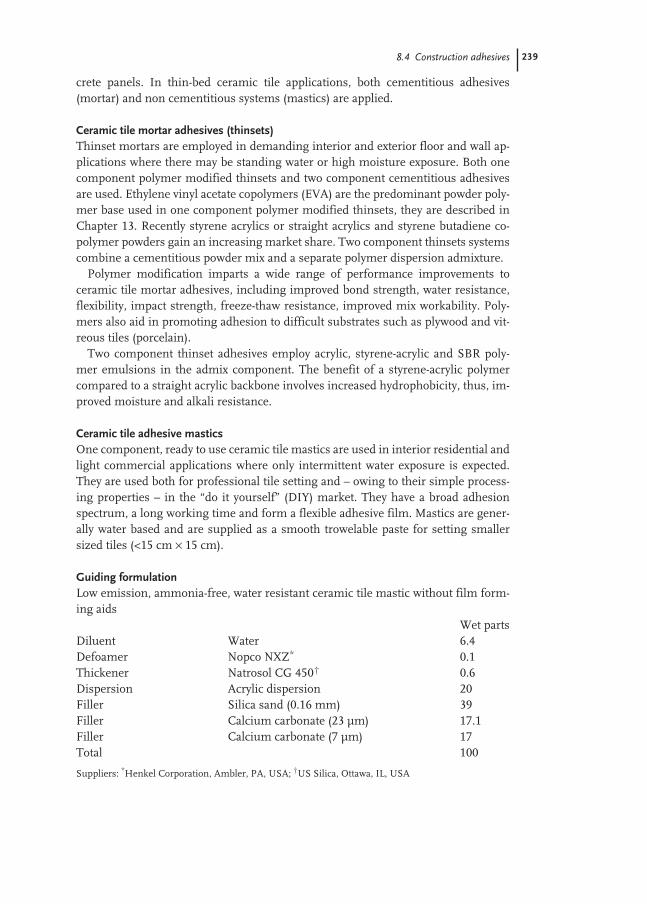
8.4 Construction adhesives 239
crete panels. In thin-bed ceramic tile applications, both cementitious adhesives(mortar) and non cementitious systems (mastics) are applied.
Ceramic tile mortar adhesives (thinsets)Thinset mortars are employed in demanding interior and exterior floor and wall ap-plications where there may be standing water or high moisture exposure. Both onecomponent polymer modified thinsets and two component cementitious adhesivesare used. Ethylene vinyl acetate copolymers (EVA) are the predominant powder poly-mer base used in one component polymer modified thinsets, they are described inChapter 13. Recently styrene acrylics or straight acrylics and styrene butadiene co-polymer powders gain an increasing market share. Two component thinsets systemscombine a cementitious powder mix and a separate polymer dispersion admixture.
Polymer modification imparts a wide range of performance improvements toceramic tile mortar adhesives, including improved bond strength, water resistance,flexibility, impact strength, freeze-thaw resistance, improved mix workability. Poly-mers also aid in promoting adhesion to difficult substrates such as plywood and vit-reous tiles (porcelain).
Two component thinset adhesives employ acrylic, styrene-acrylic and SBR poly-mer emulsions in the admix component. The benefit of a styrene-acrylic polymercompared to a straight acrylic backbone involves increased hydrophobicity, thus, im-proved moisture and alkali resistance.
Ceramic tile adhesive masticsOne component, ready to use ceramic tile mastics are used in interior residential andlight commercial applications where only intermittent water exposure is expected.They are used both for professional tile setting and – owing to their simple process-ing properties – in the “do it yourself” (DIY) market. They have a broad adhesionspectrum, a long working time and form a flexible adhesive film. Mastics are gener-ally water based and are supplied as a smooth trowelable paste for setting smallersized tiles (<15 cm × 15 cm).
Guiding formulationLow emission, ammonia-free, water resistant ceramic tile mastic without film form-ing aids
Wet partsDiluent Water 6.4Defoamer Nopco NXZ* 0.1Thickener Natrosol CG 450† 0.6Dispersion Acrylic dispersion 20Filler Silica sand (0.16 mm) 39Filler Calcium carbonate (23 µm) 17.1Filler Calcium carbonate (7 µm) 17Total 100
Suppliers: *Henkel Corporation, Ambler, PA, USA; †US Silica, Ottawa, IL, USA

240 8 Applications in the Adhesives and Construction Industries
Action of the additivesCellulosic thickeners (Natrosol) are used to adjust the viscosity and regulate mix con-sistency, working time and spreadability. Special thickeners (Attagel 50, an atta-pulgite clay) are used to generate a flow barrier, so that the tiles do not slip undertheir own weight. In cementitious systems, cellulosics are used to provide water forcement hydration over an extended time period due to their natural tendency toretain water. Surfactants improve the homogeneity and shelf life of adhesives withhigh filler content and also have a tendency to extend open time.
Preparation of polymer-emulsion-based CTA masticsAdditives are incorporated into the polymer emulsion in the stated sequence. Theadditives are added in portions, and the mixture is stirred after each addition until itis smooth again. These high-viscosity mastic adhesives (ca. 500 000 mPa s) can inprinciple be prepared using any mixing equipment with an appropriate stirrer geom-etry. Planetary mixers and turbulent mixers are particularly recommended. Preserv-atives are added to the adhesives to protect them against microbiological attack.
Test methods for assessing tile adhesivesWell defined test methods are available in North America and Europe for evaluatingceramic tile adhesives. Test methods used in Germany for emulsion-based masticsare described in DIN EN 1324 (adhesive shear strength) and DIN EN 1346 (correc-tion or adjustment time). Cementbased CTA are tested by DIN EN 1348 (pull ofstrength) and again DIN EN 1346 (open time). Classification is determined for bothtypes of adhesives by prDIN EN 12004. North American test methods and specifica-tions for tile adhesives are described in the following American National StandardsInstitute (ANSI) standards:One-component CTA mastics with glazed wall tiles ANSI 136.1Latex-Portland cement mortar with glazed wall tile, quarry tile and porcelain and/or mosaic tile ANSI 118.4Latex-Portland cement mortar with quarry tile on plywood ANSI 118.11
DIN MethodsIn the pull-off strength test performed with cementions CTA, the tile adhesive is firstapplied to concrete. After 20 min, earthenware tiles (50 mm × 50 mm) are pressedinto the adhesive bed. After a storage time under standard atmospheric conditions,tension anchors (50 mm × 50 mm) are attached to the smooth tile surface using atwo-component adhesive (epoxy). A tensile tester is used to measure the force need-ed to detach the tile from the concrete; it must be greater than 0.5 N mm–2.
To estimate adjustment time, earthenware tiles are laid in the adhesive bed as de-scribed above, rotated by 90° after 10 min and then rotated back into the original po-sition. The adhesion pull strength after storage must still be at least 0.5 N mm–2.Also described in DIN 18156 Part 3 is a method for evaluating vertical slip of tilesunder their own weight.
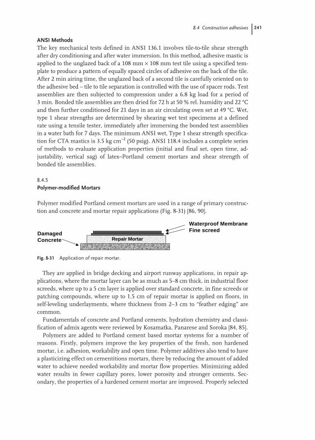
8.4 Construction adhesives 241
ANSI MethodsThe key mechanical tests defined in ANSI 136.1 involves tile-to-tile shear strengthafter dry conditioning and after water immersion. In this method, adhesive mastic isapplied to the unglazed back of a 108 mm × 108 mm test tile using a specified tem-plate to produce a pattern of equally spaced circles of adhesive on the back of the tile.After 2 min airing time, the unglazed back of a second tile is carefully oriented on tothe adhesive bed – tile to tile separation is controlled with the use of spacer rods. Testassemblies are then subjected to compression under a 6.8 kg load for a period of3 min. Bonded tile assemblies are then dried for 72 h at 50 % rel. humidity and 22 °Cand then further conditioned for 21 days in an air circulating oven set at 49 °C. Wet,type 1 shear strengths are determined by shearing wet test specimens at a definedrate using a tensile tester, immediately after immersing the bonded test assembliesin a water bath for 7 days. The minimum ANSI wet, Type 1 shear strength specifica-tion for CTA mastics is 3.5 kg cm–2 (50 psig). ANSI 118.4 includes a complete seriesof methods to evaluate application properties (initial and final set, open time, ad-justability, vertical sag) of latex–Portland cement mortars and shear strength ofbonded tile assemblies.
8.4.5
Polymer-modified Mortars
Polymer modified Portland cement mortars are used in a range of primary construc-tion and concrete and mortar repair applications (Fig. 8-31) [86, 90].
They are applied in bridge decking and airport runway applications, in repair ap-plications, where the mortar layer can be as much as 5–8 cm thick, in industrial floorscreeds, where up to a 5 cm layer is applied over standard concrete, in fine screeds orpatching compounds, where up to 1.5 cm of repair mortar is applied on floors, inself-leveling underlayments, where thickness from 2–3 cm to “feather edging” arecommon.
Fundamentals of concrete and Portland cements, hydration chemistry and classi-fication of admix agents were reviewed by Kosamatka, Panarese and Soroka [84, 85].
Polymers are added to Portland cement based mortar systems for a number of reasons. Firstly, polymers improve the key properties of the fresh, non hardenedmortar, i.e. adhesion, workability and open time. Polymer additives also tend to havea plasticizing effect on cementitions mortars, there by reducing the amount of addedwater to achieve needed workability and mortar flow properties. Minimizing addedwater results in fewer capillary pores, lower porosity and stronger cements. Sec-ondary, the properties of a hardened cement mortar are improved. Properly selected
Fig. 8-31 Application of repair mortar.
Repair MortarDamagedConcrete
Waterproof MembraneFine screed
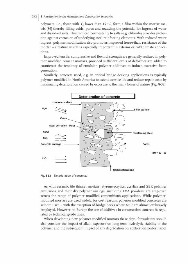
242 8 Applications in the Adhesives and Construction Industries
polymers, i.e., those with Tg lower than 15 °C, form a film within the mortar ma-trix [86] thereby filling voids, pores and reducing the potential for ingress of waterand dissolved salts. This reduced permeability to salts (e.g. chloride) provides protec-tion against corrosion of underlying steel reinforcing elements. With reduced wateringress, polymer modification also promotes improved freeze-thaw resistance of themortar – a feature which is especially important in exterior or cold climate applica-tions.
Improved tensile, compressive and flexural strength are generally realized in poly-mer modified cement mortars, provided sufficient levels of defoamer are added tocounteract the tendency of emulsion polymer additives to induce excessive foamgeneration.
Similarly, concrete used, e.g. in critical bridge decking applications is typicallypolymer modified in North America to extend service life and reduce repair costs byminimizing deterioration caused by exposure to the many forces of nature (Fig. 8-32).
As with ceramic tile thinset mortars, styrene-acrylics, acrylics and SBR polymeremulsions and their dry polymer analogs, including EVA powders, are employedacross the range of polymer modified cementitious applications. While polymer-modified mortars are used widely, for cost reasons, polymer modified concretes areseldom used – with the exception of bridge decks where SBR are almost exclusivelyemployed. However, in Europe the use of additives in construction concrete is regu-lated by technical guide lines.
When developing new polymer modified mortars these days, formulators shouldalso consider the impact of alkali exposure on long-term hydrolytic stability of thepolymer and the subsequent impact of any degradation on application performance
Fig. 8-32 Deterioration of concrete.
H 2O
Deterioration of concrete
concrete surface
Filler particle
Reinforcing steel
Pores
pH = 12 - 13
Carbonation zone
CO2
SO2
CaCl
Concrete damage
Steel corrosion - Rust
Crack

8.4 Construction adhesives 243
and service life. By their very nature, SBR are inherently resistant to alkali inducedhydrolysis compared to some vinyl acetate containing polymers which, by virture ofthe vinyl ester linkage, are more prone to hydrolysis.
Guiding FormulationsRepair mortarPart A: Liquid Component
Wet partsDispersion Carboxylated SB 54Diluent Hydration water 83Part B: Dry ComponentFiller Silica sand 721Cement Portland cement 273Filler Microsilica 6
Polymer/cement ratio 0.1Water/cement ratio 0.4
Performance after 1 day 28 daysFlexural strength (bar) 60 110Compressive strength (bar) 270 560
Test methodsThe test methods are summarized in Chapter 13.
8.4.6
Waterproofing Membranes
Concrete is the most prevalent building material used in the world today [84, 86].While concrete typically exhibits tremendously high strengths, the fact remains thatit is nevertheless porous in nature and thus, is susceptible to direct moisture pene-tration and water vapor ingress. Additionally, acids (i.e. CO2, SO2) may penetrate intothe concrete and lower the pH of cementitious materials. Along with migration ofchloride and other salts dissolved in water deep within the concrete, this may causesevere irreversible damage to steel reinforcements present (i.e. corrosion). Certainadditives can be introduced into the concrete mix to minimize water and salt pene-tration (e.g. latex admixture, calcium stearate), but due to the costs involved, theseapproaches are employed in only the most demanding applications, such as, bridgedecks and parking garages. Moreover, concrete admixtures do not protect the con-crete surface layer nor are they able to eliminate moisture penetration in cases wheredirect hydrostatic pressure forces exist – protective waterproofing membranes areneeded.
A host of different commercial waterproofing systems have been developed to pro-tect against the harmful effects associated with water intrusion into concrete. Thesecan be broken down into pre-formed membrane sheets and applied coating systems.

244 8 Applications in the Adhesives and Construction Industries
Pre-formed membrane sheets typically consist of rubber modified bitumen support-ed on a polyethylene web with a release liner to protect the highly adhesive bitumenlayer. These products are available in rolls with total membrane thickness of approx-imately 1–2 mm and can be fiberglass-reinforced to provide improved membranedimensional stability. The adhesive nature of the rubber-modified bitumen assuresexcellent sealing at the roll overlaps. A host of applied coating systems exist based on rubberized bitumen emulsions, solvent borne synthetic rubber and asphalt solutions, two-part epoxies, two-part self-curing bitumen-free liquid applied mem-branes [91], one-component water-based elastic coatings, and flexible one or two-component cementitious waterproofing slurries. Water based systems employingpolymer emulsion binders will be discussed further below.
Waterproofing products are used in a wide range of construction and repair appli-cations, applied directly on to pre-formed concrete, concrete blocks, bricks, and stoneproducts. The most important applications include foundation building walls,bridges, balconies and terraces, tunnels, basements, planters, silos, and parkingdecks. Coating systems are typically applied to uniform thickness (1–3 mm) using abrush, roller, trowel or spray system. In all cases, strong adhesion and intimate con-tact of the waterproofing layer to the underlying substrate, as well as proper water-proof system design, are required to eliminate water seepage through or around themembrane. Depending on the application, waterproofing membranes should alsoexhibit chemical resistance (e.g. to oils and acids), should remain flexible over all po-tential use temperatures and be capable of resisting hydrostatic pressures, even overcracks.
Both, one-component, water-based elastic coatings and one or two-componentflexible cementitious waterproofing slurries have the advantage that, by virtue of thewater carrier, they are environmentally friendly and easy to clean after application.They both yield monolithic, seamless, puncture resistant and watertight layers aftercuring but which nevertheless allow water vapor to escape from the inside to the out-side. Cementitious systems are particularly ideal on damp substrates – because ofhydration reactions which occur in the freshly applied membrane. As they consist ofpolymeric binder, sand and Portland cement, through hydration reaction chemistrythey become integrally bonded to and thereby become a part of the underlying con-crete. Minor cracks can be bridged at low temperatures, if a sufficiently low Tg, flexi-ble polymer dispersion binder component is selected [87, 93]. Elastic waterproofingmembranes used on the exterior of concrete structures should also exhibit resistanceto the damaging effects of UV radiation, sulfur dioxide and acid rain, carbon dioxide(carbonation), and repeated freeze-thaw cycles.
Rubber based waterproofing systems are typically based on styrene-butadienecopolymers and SBS resins while acrylic and styrene-acrylic dispersions are em-ployed in most flexible one-component and two-component cementitious mem-brane systems.
In Europe, new regulations defined in ZTV-SIB (Additional Technical ContractConditions and Regulations for the Protection and Restoration of Concrete BuildingComponents) specify crack-bridging at –20 °C [88]. As a result, lower Tg polymer sys-tems have been developed, which yield membrane flexibility and hairline crack

8.4 Construction adhesives 245
bridging at lower use temperatures. The industry has moreover shifted to systemscontaining, as a rule, higher proportions of polymer binder (0.8 < polymer/cementratio < 1) compared with earlier membrane systems.
Guiding formulations1. One-component flexible waterproofing membrane (500 µm dry film)
Wet partsDiluent Water 123.0Defoamer BYK 035* 5.5Freeze–thaw additive Propylene glycol 27.1Pigment disperser Pigment disperser NL† 5.5Surfactant Triton X-405‡ 1.6Thickener Natrosol 250 MXR§ 0.8White pigment Kronos 2101 TiO2
# 134.5Filler Duramite** 318.2Filler Atomite** 16.4Filler Microtalc MP 10-52†† 99.5Biocide Proxel GXL‡‡ 3.3
Grind until smooth, then addPolymer binder Acrylic dispersion 475.7Defoamer BYK 035* 7.4Thickener Natrosol 250 MXR 2.8Neutralizing agent Ammonium hydroxide 1.8Total 1223Pigment volume concentration: 42.3 %; solids content: 72.8 %
2. Two-component flexible cementitious waterproofing membraneDry component Wet component
F-110 Silica sand§§ 28.0 –F-95 Silica sand§§ 27.3 –Portland cement type I/II## 19.6 –Pigment disperser N† 0.2 –Lumiten E-P3108 defoamer 1.6 –Styrene acrylic dispersion – 20.6Antifoam – 0.2Water (to desired flow) – 0.5
Mix dry and wet components separately, then blend dry mix into the wet phase.Apply two or three layers of 400–600 µm each.Water/cement ratio: 0.45; sand/cement ratio: 2.82; dry polymer/cement ratio: 0.60
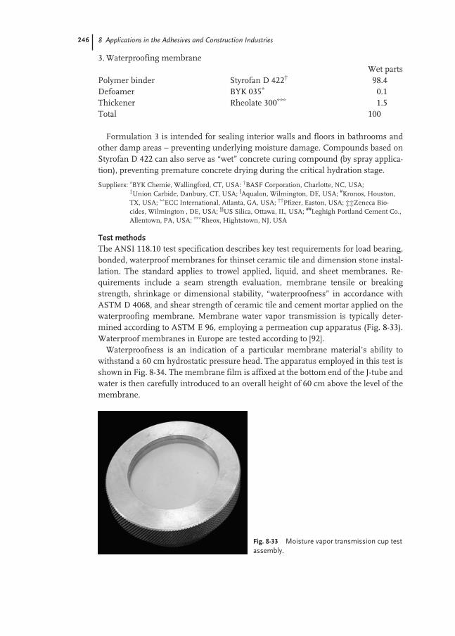
246 8 Applications in the Adhesives and Construction Industries
3. Waterproofing membraneWet parts
Polymer binder Styrofan D 422† 98.4Defoamer BYK 035* 0.1Thickener Rheolate 300*** 1.5Total 100
Formulation 3 is intended for sealing interior walls and floors in bathrooms andother damp areas – preventing underlying moisture damage. Compounds based onStyrofan D 422 can also serve as “wet” concrete curing compound (by spray applica-tion), preventing premature concrete drying during the critical hydration stage.
Suppliers: *BYK Chemie, Wallingford, CT, USA: †BASF Corporation, Charlotte, NC, USA; ‡Union Carbide, Danbury, CT, USA; §Aqualon, Wilmington, DE, USA; #Kronos, Houston,TX, USA; **ECC International, Atlanta, GA, USA; ††Pfizer, Easton, USA; ‡‡Zeneca Bio-cides, Wilmington , DE, USA; §§US Silica, Ottawa, IL, USA; ##Leghigh Portland Cement Co.,Allentown, PA, USA; ***Rheox, Hightstown, NJ, USA
Test methodsThe ANSI 118.10 test specification describes key test requirements for load bearing,bonded, waterproof membranes for thinset ceramic tile and dimension stone instal-lation. The standard applies to trowel applied, liquid, and sheet membranes. Re-quirements include a seam strength evaluation, membrane tensile or breakingstrength, shrinkage or dimensional stability, “waterproofness” in accordance withASTM D 4068, and shear strength of ceramic tile and cement mortar applied on thewaterproofing membrane. Membrane water vapor transmission is typically deter-mined according to ASTM E 96, employing a permeation cup apparatus (Fig. 8-33).Waterproof membranes in Europe are tested according to [92].
Waterproofness is an indication of a particular membrane material’s ability towithstand a 60 cm hydrostatic pressure head. The apparatus employed in this test isshown in Fig. 8-34. The membrane film is affixed at the bottom end of the J-tube andwater is then carefully introduced to an overall height of 60 cm above the level of themembrane.
Fig. 8-33 Moisture vapor transmission cup testassembly.
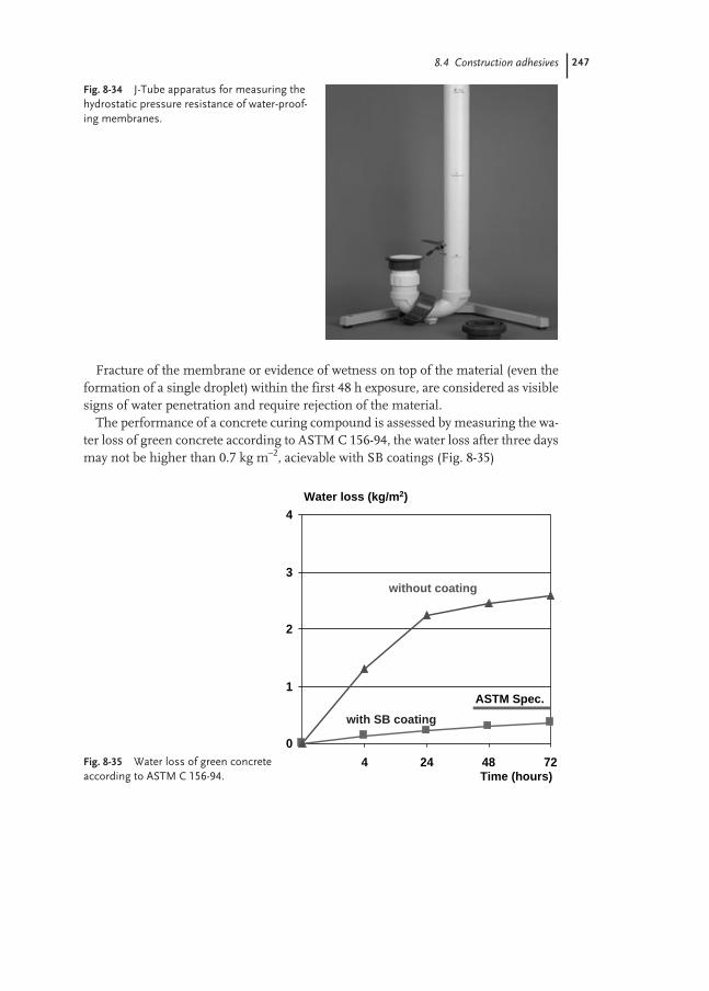
8.4 Construction adhesives 247
Fracture of the membrane or evidence of wetness on top of the material (even theformation of a single droplet) within the first 48 h exposure, are considered as visiblesigns of water penetration and require rejection of the material.
The performance of a concrete curing compound is assessed by measuring the wa-ter loss of green concrete according to ASTM C 156-94, the water loss after three daysmay not be higher than 0.7 kg m–2, acievable with SB coatings (Fig. 8-35)
Fig. 8-34 J-Tube apparatus for measuring thehydrostatic pressure resistance of water-proof-ing membranes.
Fig. 8-35 Water loss of green concreteaccording to ASTM C 156-94.
0
1
2
3
4
4 24 48 72
Water loss (kg/m2)
Time (hours)
ASTM Spec.
without coating
with SB coating

248 8 Applications in the Adhesives and Construction Industries
8.4.7
Elastomeric Roof Coatings
Water based elastomeric roof coatings can be described as formulated liquid prod-ucts, that are applied by spray or roller coating to a sloped roof surface, which havethe ability to form a continuous protective polymer film over the substrate uponevaporation of the water. Elastomeric roof coatings are used in repair applications toseal existing roof structures and also in new building construction applications, par-ticularly for protecting polyurethane insulating foam roofs. Elastomeric polymerfilms require a proper balance of properties for the film to expand and contract andreturn to its original state every time external stress-strain forces have been appliedand removed. Acrylic polymer dispersions are ideal for the manufacture of waterbased liquid elastomeric roof coatings.
In particular, white pigmented roof coating membranes are becoming increasing-ly prevalent as a result of a new EPA program called “Energy Star”. This program isaimed at promoting energy efficient buildings and in doing so, reduce building heat-ing and/or cooling costs [89]. The program requires the roof membrane to demon-strate both a minimum initial solar reflectivity and maintenance of that solar re-flectance after three years field exposure (by ASTM E 903). Buildings covered withwhite coatings, compared to black asphalt type roofs, reflect rather than absorb lightradiation resulting in cooler surface temperatures and reduced cooling demands forbuildings located in hot climates.
While field exposure conditions can vary, the Tg for an elastomeric copolymershould be lower than the minimum low temperature for a given geographic regionwhere the roof coating is to be applied (i.e. <20 °C). This helps assure that duringcold weather, the membrane will remain flexible and thus, prevent the roof mem-brane from cracking under contraction stresses.
A typical “white” roof coating formulation consists of polymer dispersion mixedwith various fillers and pigments and small amounts of additives to provide stabilityand to build viscosity to the roof coating mixture. The mixture is applied to a cleanroofing substrate, in two or more coats, and upon drying forms a continuous film orcoating membrane. The polymeric component binds the materials in a monolithicstate and forms the film. This coating membrane must also be sufficiently flexible towithstand the movement of the substrate due to the diurnal cycle. It also has to pro-vide resistance to water intrusion, cracking, and weathering while maintaining adhe-sion to the substrate under all exposure conditions.
Low-Tg (–20 °C) pure acrylic dispersions provide excellent adhesion to poly-urethane roofing foam and many other construction substrates. They may containinternal crosslinking agents that crosslink the polymer film after the water has evap-orated. Crosslinking occurs both on the membrane surface and throughout the coat-ing providing required elastomeric film properties with only very slight residual sur-face tack – thereby maximizing dirt pick up resistance and long-term reflectivity.
The demand for dispersions in this market is estimated to be on the order of20 000 tons wet per annum.

8.4 Construction adhesives 249
Guiding formulationWater based elastomeric roof coating
Wet parts (g)Diluent Water 6.88Freeze Thaw Propylene glycol 2.23Dispersing aid 30 % Pigment Disperser NL* 0.45Binder Acrylic dispersion 28.45Defoamer BYK 035† 0.45TiO2 pigment Kronos 2101‡ 11.17Filler Duramite§ 26.36Filler Atomite§ 1.34Filler Microtalc MP 10-52# 18.27Biocide Proxel GXL** 0.22Grind, then add Binder Acrylic dispersion 12.78Thickener Natrosol 250 MXR†† 0.34Neutralizing agent Ammonia Solution 0.23Defoamer BYK 035† 0.91Weight % solids = 72; volume % solids = ca. 59% Pigment volume concentration = ca. 42; viscosity (Krebs) = ca. 105
Suppliers: *BASF, Charlotte, NC, USA; †BYK-Chemie USA, Wallingford, CT, USA; ‡Kronos, Houston,TX, USA; §ECC International, Roswell, GA, USA; #Pfizer, Easton, PA, USA; **Zeneca Biocides, Wilmington, DE, USA; ††Aqualon, A Div. of Hercules, Wilmington, DE, USA
Test methodsIn 1997 an American National Standard, ASTM D 6083-97a (Fig. 8-36), was issuedfor determining the acceptable performance of liquid acrylic flexible roof coatingmixtures based on laboratory testing. These specifications are based on a somewhat
Fig. 8-36 Standard specification for liquid applied acrylic coating used inroofing.
Film physical property ASTM test Requirement
After 14 days drying at room temperatureTensile strength D2370 ≥200 psig% Elongation at break D2370 ≥100 %After 1000 h aging in a xenon arc weatherometer% Elongation at break D2370 ≥100 %Accelerated weathering D4798 No cracking andcheckingLow-temperature mandrel flexibility D522 Pass (1/2 in at –15 °F)
Adhesion (wet) C 794 >2 lb in–1
Water swelling (%) D471 <20 %Permeance – inverted (perms) D1653 <50Tear resistance (lbf in–1) D624 >60 (die C)Fungi resistance (after 28 days) G21 Zero observed

250 8 Applications in the Adhesives and Construction Industries
broader set of test requirements described in Dade County Florida, Protocol PA 129-95 and Protocol PA 143-95.
The standard has minimum specifications, when testing the free film for tensilestrength, elongation at break, water swelling, permeability and tear resistance. Thesetests are carried out after a minimum of 14 days drying at standard lab conditions(22 °C and 50 % relative humidity). The coated film must also meet standards for, ad-hesion to various substrates, tensile strength, elongation at break and mandrel flexi-bility. These tests are carried out at various specified temperatures, relative humidityand aging conditions.
AcknowledgmentsThe authors would like to express their sincere thanks to the following colleagues forfriendly assistance in writing the “Applications for Adhesive and Construction In-dustries” chapter and for critical checking of the manuscript: H. Anders, G. Auchter,O. Aydin, M. Drewery, W. Druschke, P. Fickeisen, P. Fitzgerald, H. J. Fricke, R.Füßl, H. Jäger, J. Krobb, U. Licht, W. Mächtle, L. Maempel, H.W.J. Müller, J. Neu-mann, J. Pakusch, H. Seibert, B. Schuler, K.-H. Schumacher, F. Schwarz, J. Torres-Losa, J. Türk, A. Zettl, A. Zosel

251
References
1 D. J. Alner, Aspects of Adhesion, Vols 1–3,University of London Press, London,1965, 1966, 1967.
2 De Bruyne-Houwink, Klebetechnik,Berliner Union, Stuttgart 1957.
3 R. Houwink, G. Salomon, Adhesion andAdhesives, Vols 1 and 2, Elsevier, Amster-dam, 1967.
4 C. Lüttgen, Die Technologie der Klebstoffe,Wilhelm Pansegrau, Berlin, 1959.
5 M. Michel, Adhäsion und Klebetechnik,Carl Hanser, Munich, 1969.
6 R. L. Patrick, Treatise on Adhesion andAdhesives, Marcel Dekker, New York,1967.
7 E. Plath, Taschenbuch der Kitte und Kleb-stoffe, Wissenschaftliche Verlagsge-sellschaft mbH, Stuttgart, 1963.
8 J. Skeist, Handbook of Adhesives, Rein-hold, New York, 1977.
9 P. Weiss, Adhesion and Cohesion, Elsevi-er, Amsterdam, 1962.
10 Europäischer Klebstoffverband, Klebenund Dichten Adhäsion, 1997, 41, 8–9.
11 Chemical Week, March 25, 1997, pp.21–30.
12 R. Jordan, Adhäsion, 1987, 1/2, 17–29.13 H. H. Day, US Patent 3965, 1845.14 P. Beiersdorf, German Patent 20057,
1882.15 D. V. Varanese, Adhesives Age, April
2000, p. 22.16 H. Jäger, Adhäsion, 1985, 9, 32–39.17 M. Kusumgar, Adhes. Sealants Ind.,
Oct/Nov. 2000, 44–46.18 Schwartz, J., Adhes. Age, April 2000.19 Adhäsion, 1996, 40, 10–11.20 G. Auchter, J. Barwich, H. Jäger,
G. Rehmer, Adhäsion, 1993, 1/2, 14–20.21 T. Sanborn, J. Barwich, Adhes. Sealants
Ind., August 1997.22 K.-H. Schumacher, T. Sanborn, Adhes.
Sealants Ind., June/July, 2001, 42–44.23 J. W. Hagan, C. B. Mallon, M. R. Rifi,
Adhes. Age, 1979, 3, 29.24 D. L. Prentice et al., Adhes. Age 1992, 2,
18–26.26 D. Satas (ed.), Handbook of Pressure Sen-
sitive Adhesives Technology, Van NostrandReinhold, 1989.
27 W. Druschke, Adhäsion, 1987, 5, 29–32;6, 26–34.
28 D. Satas, Adhes. Age, October 1972.29 J. W. Hagan, C. B. Mallon, M. R. Rifi,
Adhes. Age, March 1979.30 A. Zosel, Colloids Polym. Sci. 1985, 263,
541.31 A. Zosel, Adhäsion 1986, 3, 14–24.32 H. Fikentscher, Cellulose Chem. 1932,
13, 58.33 L. Varela, T. Sanborn, PSTC Confer-
ence, 24th Annual Technical Seminar,May 2001.
34 A. Zettl, in: Handbook of Pressure Sensi-tive Adhesives Technology, D. Satas (ed.),Van Nostrand Reinhold, 1989.
35 R. Mildenberg, M. Sander, G. Collin,Hydrocarbon Resins, VCH, New York,1997.
36 S. W. Medina, F. V. DiStefano, Adhes.Age, February 1989.
37 R. A. Bafford, Adhes. Age, December1979.
38 J. Türk, Papier- und Kunststoff-Verarbeit-er, 1985, 5, 40.
39 J. Türk, Adhäsion, 1993, 10, 17–20.40 I. Benedek, L.J. Heymans, Pressure Sen-
sitive Adhesives Technology, MarcelDekker, New York, 1996, Chapter 9.
41 Exxon Chemicals, Adhes. Update, 1996.42 H. Jäger, Adhäsion, 1985, 9.43 R.P. Muny, Adhes. Age, August 1996,
pp. 20–24.44 K. W. Allen, J. Adhes. 1987, 21(3/4),
261–277.45 B. Blümich, P. Blümler, A. Guthausen,
C. Fülber, G. Eidmann, R. Savelsberg,Kautschuk Gummi Kunststoffe, 1997,50(7/8), 560–563.
46 F. S. Chang, Trans. Soc. Rheol. 1960, 4,75.
47 J. L. Gardon, J. Appl. Polym. Sci. 1963,7, 625.
48 S. Yamamoto, M. Hayashi, T. Inoue, J. Appl. Polym. Sci. 1975, 19, 2107.
49 D. Satas, F. Egan, Adhes. Age 1963,9(8), 22.
50 D. H. Kaelble, Trans. Soc. Rheol. 1965,9, 135.
51 D. H. Kaelble, J. Adhes. 1965, 1, 102.
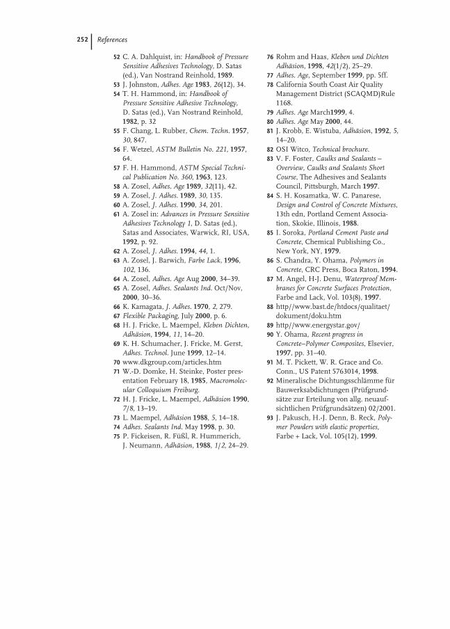
252 References
52 C. A. Dahlquist, in: Handbook of PressureSensitive Adhesives Technology, D. Satas(ed.), Van Nostrand Reinhold, 1989.
53 J. Johnston, Adhes. Age 1983, 26(12), 34.54 T. H. Hammond, in: Handbook of
Pressure Sensitive Adhesive Technology, D. Satas (ed.), Van Nostrand Reinhold,1982, p. 32
55 F. Chang, L. Rubber, Chem. Techn. 1957,30, 847.
56 F. Wetzel, ASTM Bulletin No. 221, 1957,64.
57 F. H. Hammond, ASTM Special Techni-cal Publication No. 360, 1963, 123.
58 A. Zosel, Adhes. Age 1989, 32(11), 42.59 A. Zosel, J. Adhes. 1989, 30, 135.60 A. Zosel, J. Adhes. 1990, 34, 201.61 A. Zosel in: Advances in Pressure Sensitive
Adhesives Technology 1, D. Satas (ed.), Satas and Associates, Warwick, RI, USA,1992, p. 92.
62 A. Zosel, J. Adhes. 1994, 44, 1.63 A. Zosel, J. Barwich, Farbe Lack, 1996,
102, 136.64 A. Zosel, Adhes. Age Aug 2000, 34–39.65 A. Zosel, Adhes. Sealants Ind. Oct/Nov,
2000, 30–36.66 K. Kamagata, J. Adhes. 1970, 2, 279.67 Flexible Packaging, July 2000, p. 6.68 H. J. Fricke, L. Maempel, Kleben Dichten,
Adhäsion, 1994, 11, 14–20.69 K. H. Schumacher, J. Fricke, M. Gerst,
Adhes. Technol. June 1999, 12–14.70 www.dkgroup.com/articles.htm71 W.-D. Domke, H. Steinke, Poster pres-
entation February 18, 1985, Macromolec-ular Colloquium Freiburg.
72 H. J. Fricke, L. Maempel, Adhäsion 1990,7/8, 13–19.
73 L. Maempel, Adhäsion 1988, 5, 14–18.74 Adhes. Sealants Ind. May 1998, p. 30.75 P. Fickeisen, R. Füßl, R. Hummerich,
J. Neumann, Adhäsion, 1988, 1/2, 24–29.
76 Rohm and Haas, Kleben und DichtenAdhäsion, 1998, 42(1/2), 25–29.
77 Adhes. Age, September 1999, pp. 5ff.78 California South Coast Air Quality
Management District (SCAQMD)Rule1168.
79 Adhes. Age March1999, 4.80 Adhes. Age May 2000, 44.81 J. Krobb, E. Wistuba, Adhäsion, 1992, 5,
14–20.82 OSI Witco, Technical brochure.83 V. F. Foster, Caulks and Sealants –
Overview, Caulks and Sealants ShortCourse, The Adhesives and SealantsCouncil, Pittsburgh, March 1997.
84 S. H. Kosamatka, W. C. Panarese, Design and Control of Concrete Mixtures,13th edn, Portland Cement Associa-tion, Skokie, Illinois, 1988.
85 I. Soroka, Portland Cement Paste andConcrete, Chemical Publishing Co.,New York, NY, 1979.
86 S. Chandra, Y. Ohama, Polymers inConcrete, CRC Press, Boca Raton, 1994.
87 M. Angel, H-J. Denu, Waterproof Mem-branes for Concrete Surfaces Protection,Farbe and Lack, Vol. 103(8), 1997.
88 http//www.bast.de/htdocs/qualitaet/dokument/doku.htm
89 http//www.energystar.gov/90 Y. Ohama, Recent progress in
Concrete–Polymer Composites, Elsevier,1997, pp. 31–40.
91 M. T. Pickett, W. R. Grace and Co.Conn., US Patent 5763014, 1998.
92 Mineralische Dichtungsschlämme fürBauwerksabdichtungen (Prüfgrund-sätze zur Erteilung von allg. neuauf-sichtlichen Prüfgrundsätzen) 02/2001.
93 J. Pakusch, H.-J. Denn, B. Reck, Poly-mer Powders with elastic properties,Farbe + Lack, Vol. 105(12), 1999.
253
9
Applications in the Carpet Industry
Peter R. J. Blanpain, Richard L. Scott, Onno Graalmann, and J. Arthur Smith
9.1
Introduction
This chapter covers the use of synthetic polymer dispersions in the carpet industry.In 1999, carpet accounted for approximately 60 % [1] of the volume of all floor cover-ings (soft and hard) sold in the USA, with an estimated [2] sales volume and value of1.6 billion m2 and $11.7 billion respectively. Of this volume, the tufted carpet andrug segment, the largest user of polymer dispersions, is dominant with an estimated1.4 billion m2, with broadloom’s share accounting for approximately 1.3 billion m2.Europe and the Asia-Pacific countries produced during the same period an estimat-ed 1.13 billion m2 [3] and 284 million m2 soft floor covering respectively.
Synthetic polymer dispersions have been used as binders for the backing of carpetsince the late nineteen-forties. The function of the polymeric binder in carpet back-ings is primarily to anchor the pile fibers in place, give improved dimensional stabil-ity, hand, and resistance to fraying or tuft loss at cut edges of the carpet.
Carpet backing is the fourth largest user of synthetic dispersions in North Ameri-ca (NA) after paints and coatings, paper, and adhesive applications. During 1999, dis-persion consumption in carpet backings was around 490 kt (wet) [4], which repre-sents around 9 % of the estimated 5,300 kt total dispersions (wet) produced in theUSA. In Western Europe and the Asia-Pacific regions, dispersion usage during 1999has been estimated at respectively 400 kt [3] and 100 kt wet.
9.2
History of Carpet
The history of the manufacturing of rugs and carpets began with weaving. Evidenceobtained from excavations near the Caspian Sea indicates that the spinning andweaving of sheep and goat wool was practiced as early as 6000 BC. It is known thatthe Egyptians of 3000 BC wove linen carpets ornamented by sewn on pieces of col-ored woolen cloth. A Turkish knotted pile rug, dated back to 500 BC, was found in
254 9 Applications in the Carpet Industry
Siberia in the nineteen-fifties. The weaving of hand-knotted rugs spread throughoutthe Orient, and Persia (Iran) became the predominant manufacturer.
Oriental rugs were carried to Europe by the Saracen conquerors of Spain, by re-turning Crusaders, and later Italian merchants. The Spanish in the 13th century,were the first Europeans to make hand-pile rugs. Moorish weavers were probablytaken from Spain in the 13th century to start the early French carpet weaving indus-try at Aubusson. Deep-pile rugs, called Savonneries, were first produced in Parisduring the early 17th century. The revocation of the Edict of Nantes in the late 17thcentury, that had guaranteed religious and civil freedom to French Protestants, droveFrench and Walloon Protestants (the Huguenots) into England, The Netherlandsand Germany, where they made significant contributions to the early developmentof the spinning and weaving industries in these countries. The chartering of carpetweavers in Wilton and Axminster in 1701, and the introduction of carpet productionin Kidderminster around the 1740s, was the beginning of the establishment of Eng-land as the world’s major woven carpet producer. This situation continued until the1960s, when technology developed in America for tufted carpet production was in-troduced into Europe. This resulted in woven carpet production declining in Eng-land by about 70 % by the1970s, and the establishment of Belgium, The Nether-lands, Germany, and Great Britain as Europe’s major tufted carpet manufacturers.
Before the 1790s, the carpet business in the USA was monopolized by expensivewoven imports from The United Kingdom. The US carpet industry had its modestbeginning in 1791 when William Sprague founded the first woven carpet mill inPhiladelphia. During the early 1800s, as carpet became more popular, other factorieswere established in New England, New York, and Pennsylvania. Continued domina-tion by British imports, stimulated efforts to improve methods of production, and in1839 Erastus Bigelow’s invention of the power loom, which made the mass productionof woven carpet possible, reshaped the industry. This, together with the invention ofthe Axminster loom in 1876 to produce woven carpets with a wide range of designsand colors, increases in loom widths, and other advances in technology, further stim-ulated the expansion of the US woven carpet industry. The woven carpet industrycontinued to thrive until the end of the nineteen-forties and the advent of tufted carpets.
The tufted carpet industry had its beginning in the late 19th century, when a Dal-ton (Georgia, USA) woman, Catherine Evans Whitener, produced bedspreads bysewing thick cotton yarns with a running stitch, into an unbleached muslin basecloth, and cutting the surface loops of the yarn so they would fluff out. After tufting,the material was washed to cause the muslin to shrink around the tufts to mechani-cally hold them in place. She sold the first bedspread in 1900, and generated so muchinterest that a thriving cottage industry started. Bedspreads led to other small tuftedgoods such as toilet covers, robes, and small “scatter rugs,” and by the 1930s therewere around 10 000 “Tufters” in the Dalton area.
During the late 1920s and early 1930s, increased costs, and falling prices due to in-creased competition, resulted in the development of multi-needle tufting machines,the mechanization of looms, and building of looms of greater width in order to meetdemands for more bedspreads. Tufting machines for producing carpet appeared inthe late nineteen-forties, and by the late nineteen-fifties, carpet affordable to virtually

9.3 Present Day Carpet Business 255
every home owner in the USA, was being produced in twelve foot widths, using ny-lon fiber, and jute as the secondary backing cloth. The evolution of the US carpet in-dustry since this time is depicted below in Tab. 9-1.
9.3
Present Day Carpet Business
In 1999 [2], the US carpet industry produced an estimated 1.6 billion square metersof carpet floor coverings, with a value of $11.7 billion. This represents 45 % of the to-tal world carpet production. The state of Georgia accounts for 74 % of US productionnearly all of which is concentrated in the northwest corner of the state around thecity of Dalton [7]. As shown in Tab. 9-2, tufted carpet is by far the largest carpet typeproduced with approximately 90 % of the total carpet volume, with broadloom carpetrepresenting around 90 % of the tufted volume. Second largest are the carpetsgrouped under others (knitted, knotted, needlepunched, etc.) with around 8 % of thetotal. Woven carpet has almost disappeared and today only represents around 2 % ofthe total carpet manufactured.
The situation in Europe, as indicated in Tab. 9-3, is somewhat different in that wo-ven (13 %) and needlepunched (26 %) carpet floor coverings still have an appreciableshare of the total.
In the USA tufted broadloom carpet, the most important segment of the tuftedcarpet business with an estimated 1.3 billion m2 in 1999, is constructed for use inthree markets:– consumer residential: purchases for use in a home by members of a family.– contract residential: purchases by persons other than the home owner for
new homes, apartments, condominiums, multifamilyunits, recreational vehicles, manufactured housing, etc.
Tab. 9-1 Evolution of the US carpet industry (in million m2).
Year Tufted carpet Woven carpet Total
1950 [5] 16 65 811974 [5] 724 61 7851992 [6] 1094 19 11131998 [6] 1404 30 14341999 [2] 1432 34 1466
Tab. 9-2 1999 US carpet production (in million).
m2 US $
Total Tufted 1432 10692Woven 34 450Other 129 548Total 1595 11690

256 9 Applications in the Carpet Industry
– contract commercial: purchases other than by a home owner for hotels, mo-tels, college dormitories, school rooms, business offices,banks, institutional buildings and industrial buildings.
In terms of square meters and market share percent, 1999’s production forecast(USA) [1] for the three types of carpet is summarized in Tab. 9-4.
In all three, whilst the binder used for construction may be the same, the type andformulation of the backing adhesives differ significantly, as each category of carpethas different performance specifications. The formulations employed, and methodsof adhesive application, for producing the three carpet types will be detailed in sec-tions following, together with insight into their end use property requirements.
9.4
Carpet Backing Binders
During the late nineteen-forties, the starches and natural gums initially used asbinders for improved tuft bind, were largely replaced by rubber dispersions. In thenineteen-fifties, the major binders were natural latex, cold SB (styrene-butadiene)and hot SB dispersions, the polymers usually being vulcanized to obtain goodstrength. The mid nineteen-fifties saw the introduction of non-cure hot SB disper-sions, which began to replace the sulfur cure SB. The late nineteen-fifties saw thedevelopment of carboxylated styrene-butadiene dispersions (XSB) and their intro-duction as binders for carpet backings. These XSB dispersions, as a result of theeasier and less costly compounding, faster drying rate, and improved performance in terms of specific adhesion to the fabric substrates, have since become the work-horse of the carpet backing industry. The 70s through to the early nineteen-eightieswas the era of the attached SBR foam cushion backings. Such carpets were con-
Tab. 9-4 Broadloom carpet by market type (in million).
Type m2 %
Consumer residential 707 54Contract residential 262 20Contract commercial 339 26Total broadloom 1308 100
Tab. 9-3 1999 European carpet production (in million).
m2I*
Tufted 682 6656Woven 143 1746Needlepunched 296 441Total 1121 8843
*Courtesy: GUT e.V., Aachen, Germany

9.4 Carpet Backing Binders 257
structed using a compounded XSB dispersion pre-coat or tie-coat to bind the tufts inplace, followed by the application of a foamed compound of a high solids styrene-butadiene latex (HSL), to provide under foot comfort, and prolong the useful life ofthe carpet.
Foam backing is a process in which a high solids SB dispersion, a vulcanizingagent (suspension of sulfur, zinc oxide, accelerators), chalk and emulsifier togetherwith air is frothed. The wet foam structure needs to be maintained until vulcaniza-tion takes place. This can be achieved by gelling agents which destabilize the poly-mer particles by smoothly decreasing pH and coagulating the latex within the mem-branes of the wet foam. Non-gel foam is stabilized with emulsifiers which maintainthe foam structure during the evaporation of water until vulcanization takes place.Vulcanization is carried out at about 100 °C resulting in an elastic polymer network.The polymer/filler ratio varies from 1:0.5 to 1:2.
In 1975 it was estimated that one third of all the broadloom carpet produced in theUSA had an attached SBR cushion. Unfortunately, the highly competitive situationprevailing at the time, compelled manufacturers to reduce the cost of the attachedfoam by either increasing the level of the cheap calcium carbonate filler and/or re-ducing foam application weights and density. This inevitably adversely affected thedurability of the foam to such an extent that failure occurred resulting in prematurewear of the carpet. As consequence of the bad name that attached SBR cushions ob-tained in the eyes of consumers, today HSL foam backed carpet has virtually disap-peared in the USA, with the exception of a few specialty floor coverings such as bathmats.
The situation in Europe is somewhat different to that of the United States ofAmerica. In general the styles of carpet produced in Europe have a much lower facefiber content, the pile height being much lower and pile density higher. The foambacking was also generally of higher density therefor thinner for an equivalentweight. The transfer of heat into the foam product is much easier, and enabled high-er production speeds to be achieved than were possible in the USA.
A similar situation to that observed in the USA has been experienced for similarreasons, but at a much slower speed. The consumption of HSL for foam backing re-mained fairly static for many years, the growth in the market being almost entirelyrestricted to secondary backed products, and the market share of foam backed carpetbeing gradually eroded.
In the late nineteen-nineties environmental pressure, particularly in Germany, re-sulted in a very steep decline in the consumption of HSL for floor coverings. Severalof the ingredients used in the formulations for HSL foam in the floor coverings in-dustry were brought into ecological question. Since 1998, when foam backed carpetsmade up approximately 45 % of textile floor coverings in Europe, this has decreasedto approximately 20 % in 2000.
An alternative more ecologically friendly product was required. In Europe this wasachieved by replacing the HSL foam by a needlefelt product which is adhered to thecarpet by means of an XSB latex. In North America carpet underlays made ofpolyurethane foam are commonly used to provide the soft comfort of residentialcarpets.

258 9 Applications in the Carpet Industry
Over the years, it is fair to say that virtually every type of polymer available in dis-persion form has been tried for use in the backing compound for tufted carpet. How-ever, because of its versatility and cost-effectiveness, it is the carboxylated styrene-bu-tadiene (XSB) polymer dispersions that hold the major share of this business todaywith an estimated 95 % of the volume sold in 1999, the remaining volume beingshared by ethylene-vinyl acetate, polyvinyl chloride and polyurethane dispersions.During 1999, the US carpet industry consumed approximately 490 kt wet dispersion,of which 463 kt were XSB [4]. The majority of the XSB is supplied direct to the carpetmills by the three major dispersion producers BASF, Dow Chemical, Omnova, witha minor proportion being supplied by so-called re-sellers or compounders such asGeneral Latex, Polymer Products, Southeastern Latex and Textile Rubber.
The XSB binders of today are considerably different from those at the time of theirintroduction into carpet backings. Ongoing advances in polymerization technologyhave enabled tailoring of the physical and polymeric properties of dispersions to bet-ter meet the evolving demands of present day backing machines and performancerequirements. Whilst the dispersion formulations are the proprietary information ofthe producers, some typical characteristics of the dispersions commercially availabletoday are given below.
Polymer type: Carboxylated styrene butadiene dispersion (XSB)Bound styrene: Typically in the range 60–67 %Carboxylation: Typically less than 3 % by weight of the polymer. The car-
boxylic acid may be itaconic acid alone or blends of itaconicacid with either acrylic acid or methacrylic acid. The actualtype/level of carboxylation is proprietary information to eachproducer.
Solids content: 51–53 % dry weightpH: 7.5–9.0Particle size: Up to 10 years ago, 170–200 nm used to be the norm. Today, as
consequence of the need to reduce 4-PCH content, particlesizes are generally within the 140–155 nm range.
Volatile organic Over the last 10–12 years, and the advent of “Sick Building components (VOC): Syndrome”, the dispersion producers have radically improved
their XSB manufacturing processes to minimize the level ofresidual organic compounds. Today, the maximum target val-ues, in ppm on wet dispersion, for the four major VOC are giv-en in Tab. 9-5.
Surfactants: Type and level is the proprietary information of the individualproducers. They are usually selected not only for good stabilityand low foaming during the dispersion manufacturingprocess, but also to impart the required foaming properties tothe backing binder formulations during processing in the cus-tomer’s plant.

9.5 Carpet Laminating 259
9.5
Carpet Laminating
9.5.1
Background
Several types of carpets including woven, needlepunch, knitted, and tufted are sub-jected to the latex laminating procedure [8]. By far the most prevalent carpet con-struction method is tufting. The first tufting machines were very similar to a giantsewing machine that uses thousands of threaded needles in a row across the width ofthe machine. Today’s machines are far more complex and sophisticated, althoughthey still work in the same basic way. The creel, or rack of yarn cones, are located infront of the tufter. From the creel, the yarns are passed overhead through guidetubes to puller rolls. The speed of the puller rolls controls the amount of yarn that issupplied to the tufter and, with other factors, determines the carpet’s pile height.
The needles, which number up to 2000 for very fine gauge machines, insert theyarn into a primary backing supplied from a roll of material located in front of themachine. Spiked rolls on the front of the tufting machines feed the backing throughthe machine.
Below the needle plate are loopers, devices shaped like inverted hockey sticks,timed with the needles to catch the yarn and hold it to form loops. If a cut pile iscalled for, a looper and knife combination is used to cut the loops. For cut-loop com-binations, a special looper and conventional cutting knife are used.
Tufting has reached a high degree of specialization utilizing a variety of patterningdevices, many of which are computer-controlled. Stepping, or zigzag moving, needlebars and individually controlled needles greatly expand patterning possibilities. Suchpatterned carpet is frequently referred to as a graphic pattern. Other advanced tuft-ing techniques are loop over loop and loop over cut (LOC) machines.
After completion of tufting, the unfinished tufted carpet will be dyed, if precoloredyarns are not used, followed by a finishing step to add a compound and usually a sec-ondary backing material.
Carpet laminating or backcoating is an essential step in the carpet manufacturingprocess. Since the backcoating is hidden from view, the attributes it imparts to thefinished carpet are rarely appreciated. Both the long term performance and the aes-
Tab. 9-5 Maximum limits (ppm) of volatile organic components.
North America Europe* Denmark
Styrene 35 200 40Ethylbenzene 10 50 204-Vinylcyclohexene 15 50 104-Phenylcyclohexene 60 200 50Total <400
*Defined by EPDLA (European Polymer Dispersion and Latex Association) and GuT (Association for environmental friendly carpet)
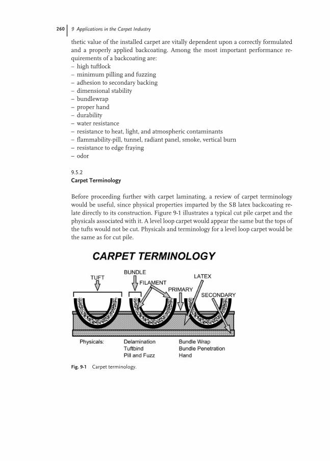
260 9 Applications in the Carpet Industry
thetic value of the installed carpet are vitally dependent upon a correctly formulatedand a properly applied backcoating. Among the most important performance re-quirements of a backcoating are:– high tuftlock– minimum pilling and fuzzing– adhesion to secondary backing– dimensional stability– bundlewrap– proper hand– durability– water resistance– resistance to heat, light, and atmospheric contaminants– flammability-pill, tunnel, radiant panel, smoke, vertical burn– resistance to edge fraying– odor
9.5.2
Carpet Terminology
Before proceeding further with carpet laminating, a review of carpet terminologywould be useful, since physical properties imparted by the SB latex backcoating re-late directly to its construction. Figure 9-1 illustrates a typical cut pile carpet and thephysicals associated with it. A level loop carpet would appear the same but the tops ofthe tufts would not be cut. Physicals and terminology for a level loop carpet would bethe same as for cut pile.
Fig. 9-1 Carpet terminology.

9.5 Carpet Laminating 261
Tuft: One cut or uncut loop of a pile fabricBundle: A continuous tufted collection of fibers or filamentsFilament: A single continuous strand of fiberPrimary: Woven or non-woven fabric into which the pile yarn is inserted
by tufting Secondary: A woven or non-woven fabric laminated to the tufted primary
to provide dimensional stabilityDelamination: The force expressed in lb/inch required to remove the second-
ary backing from the primary carpet (ASTM D 3936, ISO11857).
Tuftbind: The force expressed in pounds required to remove a single tuftfrom its primary backing (ASTM D 1335)
Pill and fuzz: Hairy effect on the carpet surface caused by slippage of indi-vidual filaments or fibers
Bundlewrap: A subjective rating, usually expressed as a percentage, to indi-cate the degree of latex encapsulating the yarn
Bundle penetration: A subjective rating, usually expressed as a percentage, to indi-cate the degree of penetration into the yarn
Hand: A subjective rating to indicate the stiffness of the finished carpet
9.5.3
Back-coating Applications
Over the last few years, direct coating with scrim lock has replaced pan application asthe preferred method for back-coating carpet. The major advantages associated withdirect coating are:– less waste (mill and disposal savings)– easier clean up– overall ease of operation– uncoated selvages (cost and clean up savings)– uniform weight control side to side– uniform coating side to side– fresh compound always available– less problems with filler fallout– higher compound solids– immediate response to cup weight changes– short lag time for compound changes– elimination of density variations (airing up or collapsing in pans)– thixotropic effects eliminated (troughing, poor pickup)– better visual weight control (puddle gain or loss seen immediately)– faster drying due to lighter densities
Figure 9-2 depicts a typical direct coating unit with scrim coat. This schematicshows a set up utilizing a bed-plate for the application of the pre-coat and a pan for theapplication of the adhesive scrim coat. Variations of this include a roll over roll forthe pre-coat application and a roll over roll or Tillitson application for the adhesive.
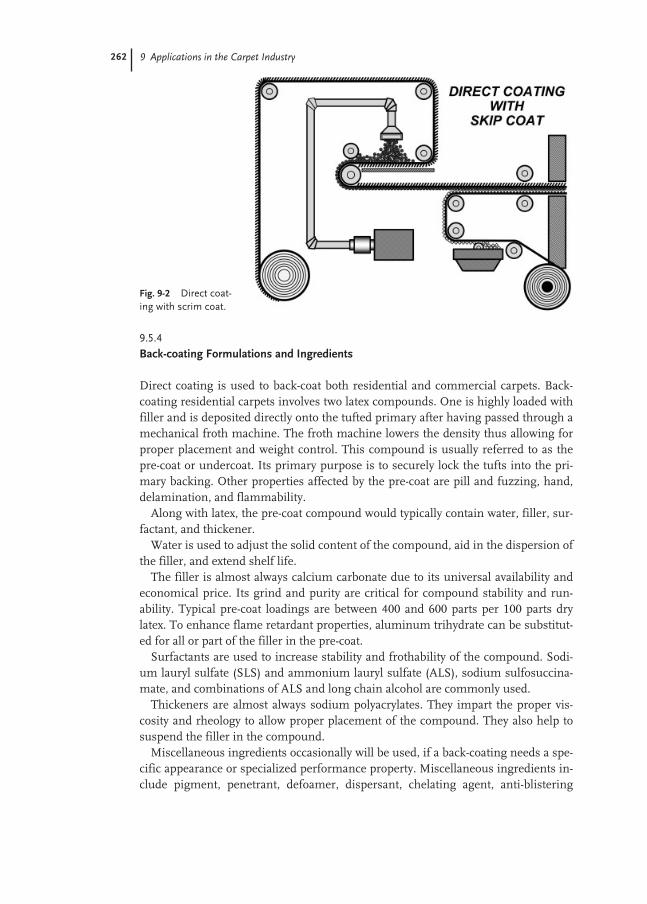
262 9 Applications in the Carpet Industry
9.5.4
Back-coating Formulations and Ingredients
Direct coating is used to back-coat both residential and commercial carpets. Back-coating residential carpets involves two latex compounds. One is highly loaded withfiller and is deposited directly onto the tufted primary after having passed through amechanical froth machine. The froth machine lowers the density thus allowing forproper placement and weight control. This compound is usually referred to as thepre-coat or undercoat. Its primary purpose is to securely lock the tufts into the pri-mary backing. Other properties affected by the pre-coat are pill and fuzzing, hand,delamination, and flammability.
Along with latex, the pre-coat compound would typically contain water, filler, sur-factant, and thickener.
Water is used to adjust the solid content of the compound, aid in the dispersion ofthe filler, and extend shelf life.
The filler is almost always calcium carbonate due to its universal availability andeconomical price. Its grind and purity are critical for compound stability and run-ability. Typical pre-coat loadings are between 400 and 600 parts per 100 parts drylatex. To enhance flame retardant properties, aluminum trihydrate can be substitut-ed for all or part of the filler in the pre-coat.
Surfactants are used to increase stability and frothability of the compound. Sodi-um lauryl sulfate (SLS) and ammonium lauryl sulfate (ALS), sodium sulfosuccina-mate, and combinations of ALS and long chain alcohol are commonly used.
Thickeners are almost always sodium polyacrylates. They impart the proper vis-cosity and rheology to allow proper placement of the compound. They also help tosuspend the filler in the compound.
Miscellaneous ingredients occasionally will be used, if a back-coating needs a spe-cific appearance or specialized performance property. Miscellaneous ingredients in-clude pigment, penetrant, defoamer, dispersant, chelating agent, anti-blistering
Fig. 9-2 Direct coat-ing with scrim coat.

9.5 Carpet Laminating 263
agent, antistatic agent, and stabilizer. A typical pre-coat formulation used in NorthAmerica is represented in Tab. 9-6.
In Europe a typical pre-coat formulation does not exist due to widely differingstyles and quality requirements. In general they contain more filler (600–1000 dryparts of calcium carbonate), less surfactant (0.2–0.5 dry parts), and less thickener (0.4dry parts), and viscosity of 3–5 Pa s.
The second compound used in residential carpet coating is referred to as theadhesive scrim or skip coat. It is applied by means of a pan and lick roll directly to thesecondary backing. This coating provides the strength necessary to sufficiently ad-here the secondary backing to the primary backing, which in turn imparts dimen-sional stability to the carpet.
The adhesive scrim coat formulation is similar to the pre-coat with two exceptions.First, since the compound is not frothed, surfactant is eliminated from the formula-tion. Secondly, since a stronger compound is required for the adhesive coating, fillerloading is reduced. Loadings between 350 and 400 parts of filler per 100 parts of drylatex are typical. Table 9-7 is representative of a typical adhesive formulation.
In Europe the ingredients for secondary backing compounds are similar but thefiller loads can vary from 0–450 parts per hundred part of dry latex. The configura-tion of the coating machines determines the compound to be used. On average theviscosity is 5 Pa s.
Since most commercial contract carpets are glued directly to the substrate, theneed for a secondary backing is eliminated. Thus most commercial contract carpets
Tab. 9-6 Pre-coat formulation (US).
Solids content (%) Dry parts Wet parts
Water – – 35XSB latex 53 100 188Calcium carbonate 100 550 550Surfactant 35 2 5.7Polyacrylate thickener 13 1 7.7Total 83 653 786
Solids content of the formulation 83 %; viscosity 17–18 Pa s
Tab. 9-7 Adhesive scrim coat formulation (US).
Solids content (%) Dry parts Wet parts
Water – – 12XSB latex 53 100 188Calcium carbonate 100 375 375Polyacrylate thickener 13 0.6 4.6Total 82 475.6 579.6
Solids content of the formulation 82 %; viscosity 9–10 Pa s
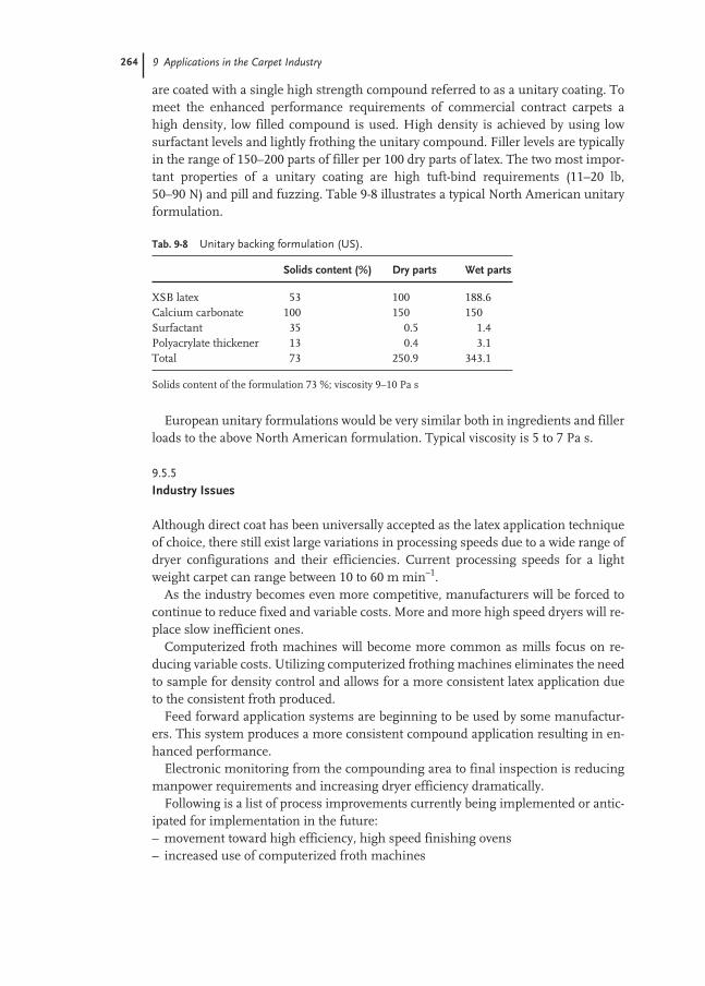
264 9 Applications in the Carpet Industry
are coated with a single high strength compound referred to as a unitary coating. Tomeet the enhanced performance requirements of commercial contract carpets ahigh density, low filled compound is used. High density is achieved by using lowsurfactant levels and lightly frothing the unitary compound. Filler levels are typicallyin the range of 150–200 parts of filler per 100 dry parts of latex. The two most impor-tant properties of a unitary coating are high tuft-bind requirements (11–20 lb,50–90 N) and pill and fuzzing. Table 9-8 illustrates a typical North American unitaryformulation.
European unitary formulations would be very similar both in ingredients and fillerloads to the above North American formulation. Typical viscosity is 5 to 7 Pa s.
9.5.5
Industry Issues
Although direct coat has been universally accepted as the latex application techniqueof choice, there still exist large variations in processing speeds due to a wide range ofdryer configurations and their efficiencies. Current processing speeds for a lightweight carpet can range between 10 to 60 m min–1.
As the industry becomes even more competitive, manufacturers will be forced tocontinue to reduce fixed and variable costs. More and more high speed dryers will re-place slow inefficient ones.
Computerized froth machines will become more common as mills focus on re-ducing variable costs. Utilizing computerized frothing machines eliminates the needto sample for density control and allows for a more consistent latex application dueto the consistent froth produced.
Feed forward application systems are beginning to be used by some manufactur-ers. This system produces a more consistent compound application resulting in en-hanced performance.
Electronic monitoring from the compounding area to final inspection is reducingmanpower requirements and increasing dryer efficiency dramatically.
Following is a list of process improvements currently being implemented or antic-ipated for implementation in the future:– movement toward high efficiency, high speed finishing ovens– increased use of computerized froth machines
Tab. 9-8 Unitary backing formulation (US).
Solids content (%) Dry parts Wet parts
XSB latex 53 100 188.6Calcium carbonate 100 150 150Surfactant 35 0.5 1.4Polyacrylate thickener 13 0.4 3.1Total 73 250.9 343.1
Solids content of the formulation 73 %; viscosity 9–10 Pa s
9.5 Carpet Laminating 265
– feed forward application systems– some carpet producers beginning to question delamination testing as best indica-
tor of “fit for use”– increased use of polypropylene fibers for commercial carpet resulting in greater
need for latex that has an affinity for polypropylene– greater need for blister resistant latex due to higher heat and more efficient ovens– increased commitments through quality partnerships by both latex producers and
carpet manufacturers in the use of statistical process control– movement towards low/zero ammonia systems to reduce emissions into the work-
place– quality issues have replaced VOC issues as the primary concern of carpet manu-
facturers.Since 1988 there has been a heightened awareness of volatile organic compounds
(VOC) emitted from carpet. In the early nineteen-nineties allegations stemmingfrom flawed scientific work arose connecting a chemical (4-PCH) emitted from car-peting to adverse health effects. 4-phenyl cyclohexene or 4-PCH is a byproduct of theSB latex manufacturing process and has a low odor threshold. It is formed by a Diels-Alder reaction of styrene and 1,3-butadiene and is responsible for “new carpet odor”.As a result of the allegations the Styrene Butadiene Latex Council (SBLC), the tradeassociation of US latex producers and the EPA (Environmental Protection Agency)undertook extensive animal toxicological testing to investigate whether there was alink between 4-PCH and adverse health effects. After exhaustive testing and numer-ous reviews, the EPA declared 4-PCH to be an “unremarkable chemical” [9]. EPA hasrepeatedly concluded that valid scientific data showed no link between 4-PCH or anyother carpet VOC emission, and adverse health effects.
Even though carpet emissions have been declared to produce no adverse health ef-fects, the issue of new carpet odor had to be addressed. As a result, the SBLC mem-ber companies have reduced VOC emissions by 95 % since 1988. With present lowVOC latex and proper drying technique, carpet manufacturers today can produceodor free carpet. As well as creating an odor free environment for the carpet con-sumer by reducing VOCs, the trend toward ammonia free latex is also creating amore worker friendly environment in the manufacturing site.
Even though alternative backing systems are available, SB latex still accounts forover 90 % of the carpet back-coating market. Due to its performance, versatility, andeconomics, SB latex continues to afford the carpet manufacturer the best value inback-coating systems today and for the foreseeable future.

266
References
1 Floor Covering Weekly, Statistical Report’99, 49(19), July 17/24, 2000.
2 US Department of Commerce, Bureauof Census, Current Industrial Reports,Carpet and Rugs, 2000.
3 Intercontuft, 2000.4 American Plastics Council Monthly
Statistical Report, December, 1999.5 L. D. Martino, Carpet Backfinishing
Review, Brunswick Corporation, 1975.
6 Carpet and Rug Institute, 1999 IndustryReview, 1999.
7 CRI The Tufted Carpet Industry, ThePride of Georgia, History and CurrentStatistics, 2000.
8 Carpet and Rug Institute, CarpetPrimer, 1997.
9 55 Federal Register 17404, April 24,1990.

267
10
Non-wovens Application
Koichi Takamura, Marilyn Wolf, and Jim Tanger
10.1
Introduction
Non-wovens are described as flat, porous sheet or web structures produced by bind-ing and interlocking fibers, yarns, or filaments by mechanical, thermal, chemical, orsolvent means. They are porous sheets that are made directly from separate fibers,molten plastic or plastic film. They are not made by weaving or knitting and do notrequire converting the fibers to yarn.
Non-woven fabrics are engineered fabrics that may be of single-use, limited life, orvery durable. They provide specific functions such as absorbency, liquid repellency,resilience, stretch, softness, strength, flame retardancy, washability, cushioning, fil-tering, bacterial barrier and sterility. These properties are often combined to createfabrics suited for specific jobs, while achieving a good balance between product use-life and cost.
In combination with other materials, non-woven fabrics provide a spectrum ofproducts with diverse properties, and are used alone or as components of apparel,home furnishing, health care, engineering, industrial, and consumer goods. Theyare categorized according to application as either disposables or durables. Somefamiliar products made with non-wovens are listed in Tab. 10-1 [1–3].
The worldwide production of non-wovens is estimated at 2.7 million tons (or6.0 billion pounds) in 1999 [4–6]. Western Europe accounts for approximately 35 %of the world production of non-woven products, followed by North America (30 %),China (12 %), Japan (12 %) and others, as shown in Fig. 10-1. The value of non-woven product shipment in North America reached an all-time high in 1997 with anapproximate value of $2.8 billion [7] and disposables account for nearly 70 % invalue. The non-woven industry in North America is expected to grow at 2–3 % annu-ally and to be $3.2 billion in 2002.
China and Japan dominate non-wovens production in Asia followed by Taiwanand Korea as shown in Fig. 10-2. Double-digit growth is expected in these countries,and production in China and Japan reached to 350 000 tons each in 2000 with an an-

268 10 Non-wovens Application
nual growth rate of 11 % [5, 6]. China non-woven production increased 87 times dur-ing the last two decades from 4000 tons in 1980.
The North American market for disposable applications was approximately$1.9 billion in 1997, and represent roughly 15.5 billion yards (13 billion m2) and900 million pounds (400 000 tons) of material. As seen in Fig. 10-3, filtration andmedical applications represent nearly 60 % of the dollar value, but fewer than 20 %
Tab. 10-1 Some familiar products made with non-wovens.
Disposable productsDiapers, sanitary napkins and tamponsSterile wraps, caps, gowns, masksDrapings used in the medical fieldHousehold and personal wipesFiltration mediaLaundry aids (fabric-dryer sheets)Embroidery backing
Durable productsApparel interliningCarpet backing and upholstery fabrics, high loft padding and backingWall coveringsAgricultural coverings and seed stripsElectronic components (i.e. battery separations, disk liners, insulation liners, polishing cloth, etc.)Envelopes, tags and labelsInsulation and house wrapsRoofing productsCivil engineering fabrics/geotextiles
Fig. 10-1 Global non-woven productionreached to 2.7 million tons in 1999. Western Europe and Asia produced approximately 35 % each.
Global Production of Nonwovens
W. Europe
North America
Asia
Fig. 10-2 China and Japan are two major non-woven producers in Asia. They reported11 % annual growth in 2000.
Nonwoven Production in Asia
Japan315 kton
Korea100 kton
China315 kton
Taiwan100 kton

10.1 Introduction 269
of disposable square yard volume. Cover stock applications dominate disposable vol-ume, and approximately 80 % of this volume is used for diaper production [7].
The volume for durable non-wovens exceeds that used for disposables in Europe.Europe has a longer history in the use of durable non-wovens, in particular geotex-tiles and roofing substrates. This is in contrast to the North American market, wheredisposable non-wovens play a stronger role as discussed above.
Electronic, Interlining, and Furniture/Bedding/Home applications account for ap-proximately 55 % of $0.9 billion non-woven materials in durable applications in theNorth American market, but furniture, bedding and home furnishing applicationsare the largest volume (42 %) of non-wovens in this durable category as shown inFig. 10-4.
North American, European and Japanese markets are shown in Fig. 10-5 compar-ing total weight of products in 1999. Hygiene (cover stock in North America and con-sumer goods in Japan) medical products and wipes account for greater than 50 % of
Fig. 10-3 1997 figures show disposable products account for nearly 70 %in the dollar value and 85 % in volume in North America.
Total $1.9 billion
Filtration
Medical
Cover Stock
Wipes
Dryer Sheets
Total 15.5 billion yard2 (13 billion m2)
Filtration
Medical
Cover Stock
WipesDryer
Sheets
Fig. 10-4 Electronic, interlining and furniture related applications accountfor 55 % of $ 0.9 billion in durable applications in North America, butfurniture related applications are the largest in volume.
Total $ 0.9 billion
Electronic
Interlining
GeotextilesFurniture/
Bedding/Home
Automotive
Construction Materials
Coating/ Laminates
Total 3.1 billion yard2 (2.6 billion m2 )
Coating/ Laminates
Construction Materials
Automotive
Furniture/ Bedding/Home
Geotextiles
Interlining
Electronic

270 10 Non-wovens Application
total production in these continents, though consumer goods in Japan appear to in-clude some durable products.
10.2
Manufacturing Systems
Early thrust in non-woven usage emphasized replacing traditional knits and wovenfabrics in low-end applications. During this initial phase, proprietary technology wasused to produce fabric structures that performed not only better than items theywere designed to replace, but often when traditional fabrics could not. As a result,new applications and markets were established and the industry expanded. Manynon-woven products listed in Fig 10-5 were virtually non-existent a generation ago.
The basic non-woven manufacturing systems have four principal elements orphases: fiber selection and preparation, web formation, web consolidation, and fin-ishing treatments.
Fig. 10-5 Non-woven applications in North America, Europe and Japanare compared by weight of products in 1999. Hygiene, medical and wipesaccount for greater than 50 % in all these continents.
North American Production (800 kton)
Filtration
Medical
CoverStock
Wipes
Dryer Sheets
Electronic
Interlining
Construction Materials
Furniture/ Bedding/ Home
Carpet Backing
Automotive
Geotextitle
Coaging/ Laminates
European Production (910 kton)
Hygiene
Garments
Footwear/ Leather Goods
Medical
Interlinings
Filtration
Upholstery/ Bed Linen
Floor Coverings
Wipes
Others
Building
Civil Engineering
Coating Substrates
Japanese Production (315 kton)
Consumer Goods
Medical
Industrial Products
Others
Construction
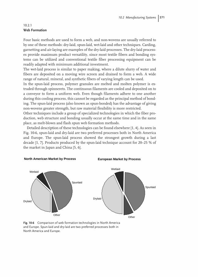
10.2 Manufacturing Systems 271
10.2.1
Web Formation
Four basic methods are used to form a web, and non-wovens are usually referred toby one of these methods: dry-laid, spun-laid, wet-laid and other techniques. Carding,garnetting and air-laying are examples of the dry-laid processes. The dry-laid process-es provide maximum product versatility, since most textile fibers and bonding sys-tems can be utilized and conventional textile fiber processing equipment can bereadily adapted with minimum additional investment.The wet-laid process is similar to paper making, where a dilute slurry of water andfibers are deposited on a moving wire screen and drained to form a web. A widerange of natural, mineral, and synthetic fibers of varying length can be used.In the spun-laid process, polymer granules are melted and molten polymer is ex-truded through spinnerets. The continuous filaments are cooled and deposited on toa conveyor to form a uniform web. Even though filaments adhere to one anotherduring this cooling process, this cannot be regarded as the principal method of bond-ing. The spun-laid process (also known as spun-bonded) has the advantage of givingnon-wovens greater strength, but raw material flexibility is more restricted.Other techniques include a group of specialized technologies in which the fiber pro-duction, web structure and bonding usually occur at the same time and in the sameplace, as melt-blown and flash spun web formation methods.
Detailed description of these technologies can be found elsewhere [1, 4]. As seen inFig. 10-6, spun-laid and dry-laid are two preferred processes both in North Americaand Europe. The spun-laid process showed the strongest growth during a lastdecade [1, 7]. Products produced by the spun-laid technique account for 20–25 % ofthe market in Japan and China [5, 6].
Fig. 10-6 Comparison of web formation technologies in North Americaand Europe. Spun-laid and dry-laid are two preferred processes both inNorth America and Europe.
European Market by Process
Drylaid
Wetlaid
Spunlaid
Other
North American Market by Process
Drylaid
Wetlaid
Spunlaid
Other
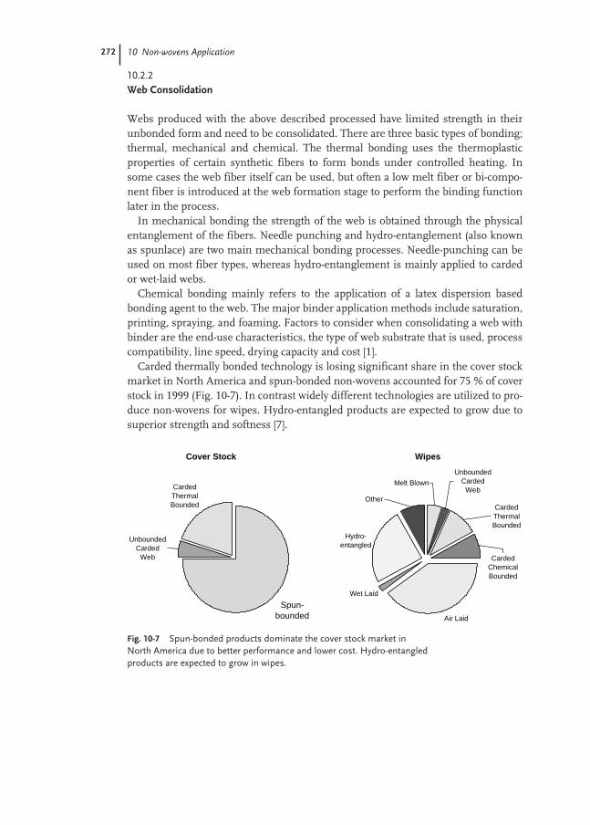
272 10 Non-wovens Application
10.2.2
Web Consolidation
Webs produced with the above described processed have limited strength in theirunbonded form and need to be consolidated. There are three basic types of bonding;thermal, mechanical and chemical. The thermal bonding uses the thermoplasticproperties of certain synthetic fibers to form bonds under controlled heating. Insome cases the web fiber itself can be used, but often a low melt fiber or bi-compo-nent fiber is introduced at the web formation stage to perform the binding functionlater in the process.
In mechanical bonding the strength of the web is obtained through the physicalentanglement of the fibers. Needle punching and hydro-entanglement (also knownas spunlace) are two main mechanical bonding processes. Needle-punching can beused on most fiber types, whereas hydro-entanglement is mainly applied to cardedor wet-laid webs.
Chemical bonding mainly refers to the application of a latex dispersion basedbonding agent to the web. The major binder application methods include saturation,printing, spraying, and foaming. Factors to consider when consolidating a web withbinder are the end-use characteristics, the type of web substrate that is used, processcompatibility, line speed, drying capacity and cost [1].
Carded thermally bonded technology is losing significant share in the cover stockmarket in North America and spun-bonded non-wovens accounted for 75 % of coverstock in 1999 (Fig. 10-7). In contrast widely different technologies are utilized to pro-duce non-wovens for wipes. Hydro-entangled products are expected to grow due tosuperior strength and softness [7].
Fig. 10-7 Spun-bonded products dominate the cover stock market inNorth America due to better performance and lower cost. Hydro-entangledproducts are expected to grow in wipes.
Cover Stock
Spun-bounded
Carded Thermal Bounded
Unbounded Carded
Web
Wipes
Air Laid
Wet Laid
Hydro-entangled
Other
Melt Blown
Unbounded Carded
Web
Carded Thermal Bounded
Carded Chemical Bounded
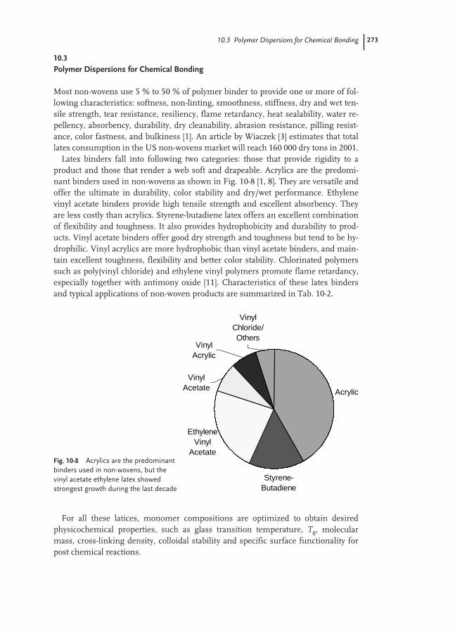
10.3 Polymer Dispersions for Chemical Bonding 273
10.3
Polymer Dispersions for Chemical Bonding
Most non-wovens use 5 % to 50 % of polymer binder to provide one or more of fol-lowing characteristics: softness, non-linting, smoothness, stiffness, dry and wet ten-sile strength, tear resistance, resiliency, flame retardancy, heat sealability, water re-pellency, absorbency, durability, dry cleanability, abrasion resistance, pilling resist-ance, color fastness, and bulkiness [1]. An article by Wiaczek [3] estimates that totallatex consumption in the US non-wovens market will reach 160 000 dry tons in 2001.
Latex binders fall into following two categories: those that provide rigidity to aproduct and those that render a web soft and drapeable. Acrylics are the predomi-nant binders used in non-wovens as shown in Fig. 10-8 [1, 8]. They are versatile andoffer the ultimate in durability, color stability and dry/wet performance. Ethylenevinyl acetate binders provide high tensile strength and excellent absorbency. Theyare less costly than acrylics. Styrene-butadiene latex offers an excellent combinationof flexibility and toughness. It also provides hydrophobicity and durability to prod-ucts. Vinyl acetate binders offer good dry strength and toughness but tend to be hy-drophilic. Vinyl acrylics are more hydrophobic than vinyl acetate binders, and main-tain excellent toughness, flexibility and better color stability. Chlorinated polymerssuch as poly(vinyl chloride) and ethylene vinyl polymers promote flame retardancy,especially together with antimony oxide [11]. Characteristics of these latex bindersand typical applications of non-woven products are summarized in Tab. 10-2.
For all these latices, monomer compositions are optimized to obtain desiredphysicochemical properties, such as glass transition temperature, Tg, molecularmass, cross-linking density, colloidal stability and specific surface functionality forpost chemical reactions.
Fig. 10-8 Acrylics are the predominantbinders used in non-wovens, but thevinyl acetate ethylene latex showedstrongest growth during the last decade
Acrylic
Styrene-Butadiene
Ethylene Vinyl
Acetate
Vinyl Acetate
Vinyl Acrylic
Vinyl Chloride/ Others
274 10 Non-wovens Application
As shown in Fig. 10-7, widely different technologies are utilized to produce wipes.This is also applicable to the binder application method. The acrylic latex can beapplied through saturation, foam impregnation or print bonding as shown inTab. 10-3.
Tab. 10-2 Basic characteristics and typical applications of latex binders used for non-wovens pro-duction.
Latex binder type Characteristics Typical applications
Polyvinyl acetate Resilient, somewhat stiff, Highloft webs, filter media, moderate durability, industrial, home furnishingslimited washability and dry-cleanability
Acrylic Excellent adhesion, stiff to soft, Coverstock, interlinings medical/excellent durability, health care, fabric softener, carder, launderability, dry-cleanability, wet wipesgood cross-linking
Vinyl acetate- Flexibility, good adhesion, Medical and/or surgical, wipes, acrylic copolymer good solvent resistance coverstock
Ethylene-vinyl acetate Good softness, durability Coverstock, wipes, air-laid pulpand adhesion
Styrene-butadiene Good tear and tensile Filters, wipes, home furnishings
Poly(vinyl chloride) Stiff to soft, can be plasticized, Scouring pads, filter media, heat sealable, low temperature wall coveringcure
Ethylene-vinyl chloride Excellent mechanical stability Underpads, highloft webs
Poly(vinyl alcohol) Resilient, water absorbent Filter media, medical
Acrylonitrile-butadiene Resilience, heat sealable, Synthetic leathercopolymer launderability, dry-cleanability
Tab. 10-3 Typical latex-based formulations for wipes with saturation, foam and print bonding methods.
Saturation Foam Impregnation Print Bonding
Materials Weight, Solids, Materials Weight, Solids, Materials Weight, Solids, g % g % g %
Acrylic latex 100 55 Acrylic latex 100 55 Acrylic latex 100 55Water 120–450 Water* 80–150 Water1 150–450Defoamer 0.1 100 Ammonia* Dye2
Surfactant 0–1 50 Surfactants 0–5 50 Thickener1
*Adjust to 10-25% solids *Adjust to 15-30% solids and pH=8 1 Adjust to 10–15% solids and 10Pas Typical foam weight of 70–150 g/liter viscosity
2 Add to the desired color

10.4 Application Test Methods 275
10.4
Application Test Methods
A series of well-defined standardized test methods have been established throughvarious trade organizations, government and university research institutes. INDA(Association of the Non-woven Fabrics Industry) Standard Test [2] and EDANA (Eu-ropean Disposables and Non-wovens Association) Recommended Test Method [4]are two major standards for non-wovens. International Standardization Organiza-tion (ISO) and the American Society for Testing and Materials (ASTM) refine andapprove a wide range of test methods developed by these trade organizations. INDAStandard Test Methods, and some corresponding EDANA, ASTM and ISO testmethods are listed in Tab. 10-4.
The crosslinking resins such as melamine can be used to enhance wet and dry ten-sile strength, moisture resistance, heat resistance and solvent resistance (dry-clean-ability) of non-woven fabrics. Figure 10-9 illustrates examples of the stiffness im-provement of an acrylic latex bonded non-woven sheet as a function of the latex levelin the sheet at two different levels of the melamine resin [12].
Here, the stiffness was measured by the Handle-O-Meter (IST 90.3), where a fab-ric specimen is pushed through a slot with a blade on an arm at a constant rate andthe resultant force on the center point of the fabric measured. Dent [13] recently re-ported through theoretical analysis that the initial slope of the load-deflection curve
Fig. 10-9 Improvement in the stiffness of an acrylic latex bonded non-woven sheet as a function of the latex level.
0
50
100
150
200
250
0 20 40 60
% Acrylic in Sheet
Han
dle-
O-M
eter
Rea
din
g, m
N
without Melamine
with 5% Melamine
with 10% Melamine

276 10 Non-wovens Application
Des
crip
tion
IND
A s
tand
ard
EDA
NA
rec
omm
ende
d A
STM
met
hod
ISO
test
met
hod
test
met
hod
Gu
idel
ine
test
met
hod
s fo
r n
on-w
oven
fab
rics
IST
GL
non
-wov
ens
AST
M D
1117
-99
Gu
idel
ine
test
met
hod
s fo
r ev
alu
atin
g n
on-w
oven
fel
tIS
T G
L fe
lts
Non
-wov
en v
ocab
ula
ryIS
T 1
ER
T 1
.3-9
9
Abs
orpt
ion
Non
-wov
en a
bsor
ptio
nIS
T 1
0.1
ER
T 1
0.3-
99IS
O 9
073.
6R
ate
of s
orpt
ion
of
wip
ing
mat
eria
lsIS
T 1
0.2
Dem
ond
abso
rben
cyIS
T 1
0.3
ER
T 2
30.0
-99
Abr
asio
n re
sist
ance
Infl
ated
dia
phra
gmIS
T 2
0.1
AST
M D
3886
-92
Fle
xin
g an
d ab
rasi
onIS
T 2
0.2
AST
M D
3885
-99
Osc
illat
ory
cylin
der
IST
20.
3A
STM
D41
57-9
2R
otar
y pl
atfo
rmIS
T 2
0.4
AST
M D
3884
-92
Mar
tin
dale
IST
20.
5 A
STM
D49
66-9
8IS
O 1
2947
-3U
nif
orm
abr
asio
n m
eth
odIS
T 2
0.6
AST
M D
4158
-92
Bur
stin
g st
reng
thD
iaph
ragm
IST
30.
1E
RT
80.
3-99
AST
M D
3786
-87
ISO
139
38-1
Non
-wov
en b
urs
tIS
T 3
0.2
Ele
ctro
stat
ic p
rope
rtie
sSu
rfac
e re
sist
ivit
yIS
T 4
0.1
ISO
907
3-6
Dec
ayIS
T 4
0.2
Tab.
10-4
IND
A S
tand
ard
Test
Met
hods
for
non-
wov
ens
and
the
corr
e-sp
ondi
ng E
DA
NA
, AST
M a
nd IS
O te
sts.

10.4 Application Test Methods 277
Des
crip
tion
IND
A s
tand
ard
EDA
NA
rec
omm
ende
d A
STM
met
hod
ISO
test
met
hod
test
met
hod
Bin
der
prop
erti
esR
esin
bin
der
dist
ribu
tion
an
d pe
net
rati
onIS
T 5
0.1
AST
M D
5908
-96
App
eara
nce
an
d in
tegr
ity
of h
igh
loft
bat
tin
gIS
T 5
0.2
AST
M D
4770
-00
Opt
ical
pro
pert
ies
Opa
city
IST
60.
1E
RT
110
.1-7
8IS
O 2
471-
198
Bri
ghtn
ess
IST
60.
2E
RT
100
.1-7
8IS
O 2
470-
1997
Per
mea
bilit
yA
ir p
erm
eabi
lity
IST
70.
1E
RT
140
.1-9
9A
STM
D73
7-96
Wat
er v
apor
tran
smis
sion
(mu
ltip
le te
sts)
IST
70.
2IS
O 9
073
8:19
95Li
quid
str
ike-
thro
ugh
tim
eIS
T 7
0.3
ER
T 1
50.4
-99
Wat
er v
apor
tran
smis
sion
(Moc
on)
IST
70.
4
Rep
elle
nce
Surf
ace
wet
tin
g sp
ray
test
IST
80.
1IS
O 4
920-
1981
(E)
Pen
etra
tion
by
wat
er (r
ain
test
)IS
T 8
0.2
Pen
etra
tion
by
wat
er (s
pray
impa
ct te
st)
IST
80.
3P
enet
rati
on b
y w
ater
(hyd
rost
atic
pre
ssu
re te
st)
IST
80.
4E
RT
120
.1-8
0IS
O 8
11-1
981
Pen
etra
tion
by
salin
e so
luti
on (a
uto
mat
ed m
ason
jar
test
)IS
T 8
0.5
ER
T 1
70.0
-89
Wat
er r
esis
tan
ce h
ydro
stat
ic p
ress
ure
test
)IS
T 8
0.6
ER
T 1
20.1
-80
ISO
811
-198
1P
enet
rati
on b
y oi
l (h
ydro
carb
on r
esis
tan
ce)
IST
80.
7A
lcoh
ol r
epel
len
ce o
f n
on-w
oven
fab
rics
IST
80.
8N
on-w
oven
s ru
n-o
ffIS
T 8
0.9
ER
T 1
52.0
-99
Sti
ffnes
sC
anti
leve
rIS
T 9
0.1
ER
T50
.5-9
9A
STM
D57
32-9
5IS
0907
3-7
Gu
rley
IST
90.
2H
andl
e-O
-met
erIS
T 9
0.3
Dra
peIS
T 9
0.4
ER
T 9
0.4-
99
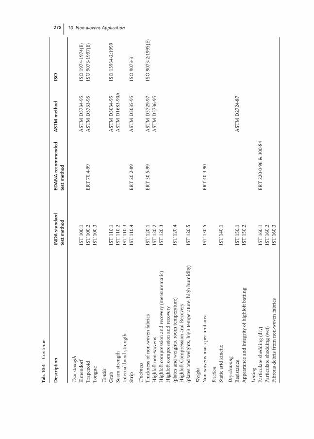
278 10 Non-wovens Application
Des
crip
tion
IND
A s
tand
ard
EDA
NA
rec
omm
ende
d A
STM
met
hod
ISO
test
met
hod
test
met
hod
Tea
r st
reng
thE
lmen
dorf
IST
100
.1A
STM
D57
34-9
5IS
O 1
974-
1974
(E)
Tra
pezo
idIS
T 1
00.2
ER
T 7
0.4-
99A
STM
D57
33-9
5IS
O 9
073-
1997
(E)
Ton
gue
IST
100
.3
Ten
sile
Gra
bIS
T 1
10.1
AST
M D
5034
-95
ISO
139
34-2
:199
9Se
am s
tren
gth
IST
110
.2A
STM
D16
83-9
0AIn
tern
al b
ond
stre
ngt
hIS
T 1
10.3
Stri
pIS
T 1
10.4
ER
T 2
0.2-
89A
STM
D50
35-9
5 IS
O 9
073-
3
Thi
ckne
ssT
hic
knes
s of
non
-wov
en f
abri
csIS
T 1
20.1
ER
T 3
0.5-
99A
STM
D57
29-9
7IS
O 9
073-
2:19
95(E
)H
igh
loft
non
-wov
ens
IST
120
.2A
STM
D57
36-9
5H
igh
loft
com
pres
sion
an
d re
cove
ry (m
easu
rem
atic
)IS
T 1
20.3
Hig
hlo
ft c
ompr
essi
on a
nd
reco
very
(pla
tes
and
wei
ghts
, roo
m te
mpe
ratu
re)
IST
120
.4H
igh
loft
Com
pres
sion
an
d R
ecov
ery
(pla
tes
and
wei
ghts
, hig
h te
mpe
ratu
re, h
igh
hu
mid
ity)
IST
120
.5
Wei
ght
Non
-wov
ens
mas
s pe
r u
nit
are
aIS
T 1
30.5
ER
T 4
0.3-
90
Fri
ctio
nSt
atic
ari
d ki
net
icIS
T 1
40.1
Dry
-cle
anin
gR
esis
tan
ceIS
T 1
50.1
AST
M D
2724
-87
App
eara
nce
an
d in
tegr
ity
of h
igh
loft
bat
tin
gIS
T 1
50.2
Lint
ing
Par
ticu
late
sh
eddi
ng
(dry
)IS
T 1
60.1
ER
T 2
20-0
-96
& 3
00-8
4P
arti
cula
te s
hed
din
g (w
et)
IST
160
.2F
ibro
us
debr
is f
rom
non
-wov
en f
abri
csIS
T 1
60.3
Tab.
10-4
Con
tinue
.
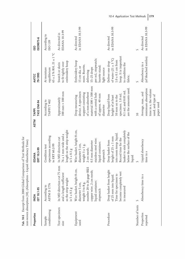
10.4 Application Test Methods 279
Tab.
10-
5E
xcer
pt f
rom
200
0 G
loba
l Com
pari
son
of
Tes
t Met
hod
s fo
rn
on-w
oven
abs
orpt
ion
[10]
. (A
bsor
ptio
n –
Liq
uid
Abs
orbe
ncy
Tim
e)
Prop
ertie
sIN
DA
EDA
NA
AST
MTA
PPI
AA
TCC
ISO
IST
10.1
-95
ERT
10.3
-99
T432
OM
-94
79-1
995
ISO
9073
-6
Sam
ple
Acc
ordi
ng
to
Con
diti
on te
st
Acc
ordi
ng
to
At m
oist
ure
A
ccor
din
g to
co
ndi
tion
ing
AST
M D
177
6sp
ecim
ens
acco
rdin
gT
AP
PI
T 4
02eq
uili
briu
m
ISO
139
to E
RT
60.
2-99
65±
2%
RH
, 21
±1
°C
Tes
t spe
cim
en
In M
D d
irec
tion
cu
t 75
mm
In
MD
dir
ecti
on c
ut
App
roxi
mat
ely
Swat
ch o
r sk
ein
A
s di
rect
ed in
si
zean
d a
len
gth
su
ffic
ien
t 76
±1
mm
wid
e an
d a
100
mm
×10
0m
mto
fit
tigh
tly
over
E
DA
NA
10.
3-99
so th
e st
rip
wei
ght
len
gth
so
the
stri
p w
eigh
t em
broi
dery
hoo
pis
5±
0.1
gis
5±
0.1
g
Equ
ipm
ent
Wir
e ba
sket
, hei
ght 8
cm,
Wir
e ba
sket
, hei
ght 8
cm,
Dro
p m
easu
rin
g E
mbr
oide
ry h
oop
As
dire
cted
u
sed
diam
eter
5cm
, di
amet
er 5
cm,
devi
ce. A
spe
cim
en
15cm
dia
. or
in E
DA
NA
10.
3-99
wei
ght 3
to 8
g,
wei
ght 3
±1
g,
supp
ort c
onsi
stin
g m
ore.
Bu
rett
e,
nu
mbe
r 20
to 2
6ga
ge B
&S
2cm
mes
h;
of a
non
-abs
orbe
nt
deliv
erin
g co
pper
wir
e, 2
cm m
esh
; 0.
5m
m d
iam
eter
m
ater
ial 1
00×
100
mm
15
–25
drop
s liq
uid
con
tain
er;
stai
nle
ss s
teel
wir
e;
wit
h a
cen
tral
hol
e pe
r m
L; s
topw
atch
; st
opw
atch
liqu
id c
onta
iner
; of
app
rox.
40
mm
bu
rett
e st
and;
st
opw
atch
diam
eter
ligh
t sou
rce
Pro
cedu
reD
rop
bask
et f
rom
hei
ght
Dro
p ba
sket
fro
m
Dro
p liq
uid
fro
m
Del
iver
on
e dr
op
As
dire
cted
of
25
mm
into
liqu
id.
hei
ght o
f 25
±1
mm
h
eigh
t of
at le
ast
of w
ater
(21
±3
°C)
in E
DA
NA
10.
3-99
Tim
e fo
r sp
ecim
en to
in
to r
oom
tem
p. li
quid
. 10
mm
on
to th
e 1.
0±
0.1
cm f
rom
be
com
e co
mpl
etel
y w
et
Rec
ord
tim
e fo
r th
e sp
ecim
en. 1
.0m
L h
oop.
It i
s im
port
ant
is m
easu
red
bask
et to
sin
k co
mpl
etel
y 0.
1m
L an
d 0.
01m
L to
con
diti
on th
e be
low
the
surf
ace
of th
e ar
e th
e am
oun
ts u
sed.
fabr
ic.
liqu
id
Nu
mbe
r of
test
s5
510
55
Pro
pert
ies
Abs
orbe
ncy
tim
e in
sLi
quid
abs
orbe
ncy
A
vera
ge, m
ax.,
and
Abs
orbe
ncy
in s
A
s di
rect
ed
repo
rted
tim
e in
sm
inim
um
abs
orpt
ion
(o
f bl
each
ed te
xtile
s)in
ED
AN
A 1
0.3-
99ti
me
in s
, th
e vo
lum
e u
sed,
an
d ty
pe o
f pa
per
use
d
280 10 Non-wovens Application
gives the fabric stiffness or flexural rigidity, while the ratio of maximum load to ini-tial slope gives the fabric friction or smoothness. Thus, a single measurement canmeasure two basic parameters governing the fabric “hand” or “feel”.
In addition, TAPPI (Technical Association of the Pulp and Paper Industry) is ac-tive in the wet-form non-woven segment of the industry [9]. Some of the standardtest methods established by AATCC (American Association of Textile Chemists andColorists) are also applicable to non-wovens. INDA recently published “2000 GlobalComparison of Test Methods” [10], which conveniently compares standard testmethods by the above listed organizations. Table 10-5 is an excerpt from the Absorp-tion – Liquid Absorbency Time, which demonstrates two different principles used toquantify similar properties.
Oathout [14] has discussed the water-absorption characteristics of eleven wipingmaterials including one 100 % wood pulp with binder, paper making process, six hy-dro-entangled, two knitted polyester and one woven cotton. In addition to the staticabsorption measurements specified by IST 10.1 and 10.2, he describes results of thedynamic wiping efficiency, or “wipe-dry” test. In this test, a wiper is affixed to thebottom side of a 1 kg sled, which is placed on a stainless steel pan. A known amountof the liquid challenge was placed in front of the sled pulled into and through thepool at a wiping speed of 25 cm s–1. The test tries to simulate manual wiping opera-tions. His results demonstrate that fabrics with bulky character, imparted throughcreping or stitch-bonding exhibited superior “wipe-dry”.

281
References
1 E. A. Vaughn, Non-wovens World Factbook 1991, ISBN 0-87930-227-5,Miller Freeman Publications, 1991.
2 Association for the Non-woven FabricsIndustry, Cary, North Carolina, USA;www.INDA.org
3 P. Wiaczek, Comparison of Trends in Latex Emulsions for Non-wovens and Textiles: China and the United States, International Non-wovens Journal, 1999.
4 EDANA – European Disposables andNon-wovens Association, Brussels, Belgium, www.edana.org
5 All Nippon Non-wovens Association;www.anna.gr.jp
6 China Non-woven Technical Association;www.chinanonwovens.com
7 Association of the Non-woven FabricsIndustry, Analysis – The Non-woven Industry in North America, Cary, North Carolina, USA.
8 B. M. Koltisko, Vinyl Copolymer Materi-als, Principles of Non-wovens, 221–248,1992, Association of the Non-woven Fabrics Industry.
9 1998-1999 TAPPI Test Methods, 1998,TAPPI Press, Atlanta, GA;www.tappi.org
10 2000 Global Comparison of TestMethods, Association of the Non-wovenFabrics Industry, 2000.
11 E. D. Weil, Flame Retardant Non-wovens, Non-wovens Binders and Additives Seminar, 53-61, TAPPIPRESS, 1988.
12 P. D. Wallace, Crosslinker resins in non-woven binder systems, Non-wovensBinders and Additives Seminar, TAPPI Press, 1988.
13 R. W. Dent, An analysis of fabric ‘Hand’and ‘Feel’, International Non-wovensJournal, Vol. 9, 2000.
14 J. M. Oathout, Determining the DynamicEfficiency with which Wiping MaterialsRemove Liquids from Surface, Interna-tional Non-wovens Journal, Vol. 9,2000.

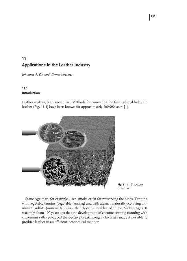
283
11
Applications in the Leather Industry
Johannes P. Dix and Werner Kirchner
11.1
Introduction
Leather making is an ancient art. Methods for converting the fresh animal hide intoleather (Fig. 11-1) have been known for approximately 100 000 years [1].
Stone Age man, for example, used smoke or fat for preserving the hides. Tanningwith vegetable tannins (vegetable tanning) and with alum, a naturally occurring alu-minum sulfate (mineral tanning), then became established in the Middle Ages. Itwas only about 100 years ago that the development of chrome tanning (tanning withchromium salts) produced the decisive breakthrough which has made it possible toproduce leather in an efficient, economical manner.
Fig. 11-1 Structure of leather.

284 11 Applications in the Leather Industry
The excellent properties of chrome-tanned leather opened up new fields of use andmade possible the mass production of leather goods, for example in the shoe or ap-parel leather sector. This created the need for fashionable styling of these leathergoods and for making them resistant to soiling and damage. It is this function that isperformed by leather finishing [1–7].
11.2
Market Situation
To describe the economic importance of polymer dispersions, a brief look at thestructure of the leather industry is helpful.
The leather industry is one of the oldest and most complex industries world-wide.It is closely coupled to raw hide production and hence to meat consumption. Live-stock is bred world-wide. Accordingly, tanneries are located all around the globe. Thearticles made from leather differ greatly, ranging from shoe upper leather to apparelleather and to automotive leather.
The leather industry has undergone global changes in the last decades. This struc-tural change is still not complete. It is driven by the high proportion of leather pro-cessing and leather production costs attributable to wages (Fig. 11-2). This has ledand is still leading to a relocation of leather manufacture from the traditional indus-trialized countries of Europe and from the U.S. to low wage countries, especially inthe Far East (Fig. 11-3). At the same time, the industry, which is predominantlybased on small and medium size companies, is undergoing a process of consolida-tion.
Fig. 11-2 Breakdown of leather pro-duction costs (without raw hide costs)in Europe.
Fig. 11-3 Regional distribution of fin-ished leather production.
Costs of leather production in Europe: ca. 7.5 e/m2

11.2 Market Situation 285
Since finished leather production is determined by raw hide production (Fig.11-4),the annual growth rate of leather produced is only small (ca. 0.8 % year–1). The pre-dominant portion of leather produced is cattle hide (ca. 60 %), followed by small-an-imal skins (sheep, goat) at about 30 % and pork leather at ca. 10 %.
The market volume of chemicals used in leather manufacture is about Euro2.5 billion world-wide. The largest segment by far in terms of value is the productrange for tanning (ca. 50 %), followed by finishing (ca. 30 %). The finishing segmentsubdivides into the categories of binders/top coats, finishing dyes and finishing aux-iliaries (Fig. 11-5).
Base coats and pigmented coats are today already commonly applied in low-sol-vent and solvent-free processes. Polyacrylate or polybutadiene dispersions are pre-ferred here. Polyurethane dispersions and casein formulations are used as well,depending on the end use. In the case of top coats, aqueous systems based onpolyurethane dispersions are used as well as, still, solvent-containing lacquers oremulsions. However, here too increasingly tougher environmental regulations aredriving a changeover to solvent-reduced and waterborne systems.
About 180 000 tons annum–1 of binders are estimated to be used in leather finish-ing world-wide. Of that, about 60 % are polyacrylate and polybutadiene dispersionsand about 12 % polyurethane dispersions (Fig. 11-6). At about 20 %, the solvent-con-taining lacquers still account for a relatively large share today. However, this sharewill in future decrease further in favor of polyurethane dispersions.
Fig. 11-5 Distribution of market volume in leather finishing between individual product ranges.
Fig. 11-4 World-wide raw hideproduction in 1990 to 1995.
Finishing market volume: ca. e 0.75 billion
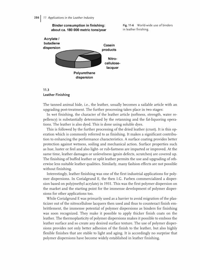
286 11 Applications in the Leather Industry
11.3
Leather Finishing
The tanned animal hide, i.e., the leather, usually becomes a sailable article with anupgrading post-treatment. The further processing takes place in two stages:
In wet finishing, the character of the leather article (softness, strength, water re-pellency) is substantially determined by the retanning and the fat-liquoring opera-tions. The leather is also dyed. This is done using soluble dyes.
This is followed by the further processing of the dried leather (crust). It is this op-eration which is commonly referred to as finishing. It makes a significant contribu-tion to enhancing the performance characteristics. A surface coating provides betterprotection against wetness, soiling and mechanical action. Surface properties suchas hue, luster or feel and also light- or rub-fastness are imparted or improved. At thesame time, leather damages or unlevelness (grain defects, scratches) are covered up.The finishing of buffed leather or split leather permits the use and upgrading of oth-erwise less suitable leather qualities. Similarly, many fashion effects are not possiblewithout finishing.
Interestingly, leather finishing was one of the first industrial applications for poly-mer dispersions. In Corialgrund E, the then I.G. Farben commercialized a disper-sion based on poly(methyl acrylate) in 1931. This was the first polymer dispersion onthe market and the starting point for the immense development of polymer disper-sions for other applications too.
While Corialgrund E was primarily used as a barrier to avoid migration of the plas-ticizer out of the nitrocellulose lacquers then used and thus to counteract finish em-brittlement, the immense potential of polymer dispersions as binders for finishingwas soon recognized. They make it possible to apply thicker finish coats on theleather. The thermoplasticity of polymer dispersions makes it possible to emboss theleather surface and so create any desired surface texture. The use of polymer disper-sions provides not only better adhesion of the finish to the leather, but also highlyflexible finishes that are stable to light and aging. It is accordingly no surprise thatpolymer dispersions have become widely established in leather finishing.
Fig. 11-6 World-wide use of binders in leather finishing.

11.3 Leather Finishing 287
11.3.1
Modern Finishing
The various leather articles with their specific requirements each require a specificoptimized process in the tannery. Classifying leather finishes according to, say, thebinders used or the method of application, the appearance or the ready-producedleather article is thus possible only to a limited extent. Frequently there are many dif-ferent ways of producing the desired article. Leather finishing is therefore regardedas being more an art than a science.
11.3.2
General Construction of Finishing Coats
The finish is generally made up of a number of coats. Each coat has a certain pur-pose. The coating technique can be the same for each coat, but need not be. Itdepends primarily on the type of leather used and the effect desired.
11.3.3
Spray Dyeing
Metallized dyes, for example, are used to dye, or correct the hue of the surface ofleathers which have not been drum dyed and to match it to the hue of the finish. Asa result, damages to the finish in the course of the use of the leather article are lesspronounced.
11.3.4
Grain Impregnation
Grain impregnation is used to improve the firmness of the buffed grain layer. Theimpregnating float or liquor has to absorb into the leather and must not become de-posited at the surface. To this end, very dilute, finely divided acrylate dispersions(solids content about 10 %) are applied in combination with capillary-active sub-stances known as penetrators.
11.3.5
Base Coat
Depending on the crust leather used, the adhesion of the finish layer to the leatherhas to be improved in some cases by means of a separate base coat. Adequate adhe-sion is the precondition for many application properties and important to achieve therequired physical fastnesses for the ready-produced leather articles. Soft, finely di-vided polyurethane dispersions have won out in this sector over polyacrylate disper-sions.

288 11 Applications in the Leather Industry
11.3.6
Pigment Coat
Its components are pigments, binders and auxiliaries such as waxes and fillers. Thepigment coat imparts the desired appearance to the leather and levels out the leathersurface. The choice of binders is made according to the finishing effect and fastnessprofile desired. Generally, polyacrylate dispersions are used in the pigment coat.
A distinction is made between finishes which preserve the natural character of theleather (e.g., semi-aniline finish) and high hiding finishes which receive the desiredgrain structure through embossment. Finely divided acrylate dispersions (<100 nm)are useful for less hiding finishes. The butadiene-based dispersions used in leatherfinishing have high filling effect and can enhance the hiding power of the finish.
As well as the degree of hiding, the hardness/softness balance of the pigment coathas a significant influence on application and processing properties. Especially onthin, soft leather types (e.g., nappa), hard pigment coats lead to an unwanted double-skin appearance. Soft binders, however, tend to be tacky and cause processing prob-lems in leather production. Auxiliaries (waxes and fillers) can be used to reduce thetackiness within certain limits. The glass transition temperatures of the polyacrylatedispersions used are typically between –10 and +10 °C.
Polyurethane dispersions are used in the pigment coat in particular when veryhigh fastness properties are required.
11.3.7
Top Coat
The top coat determines the ultimate appearance and the feel of the leather surface.It further substantially influences the fastness properties of the finish. Instead of or-ganic, solvent-containing lacquers and top coats (e.g., nitrocellulose emulsions), to-day there is an increasing trend towards waterborne top coat systems. These are usu-ally polyurethane dispersions which, owing to their specific properties (no emulsifi-er, good film formation despite relatively high hardness), are superior to polyacrylatedispersions in application terms.
The degree of luster of the finish is controlled using matting agents (e.g., silica de-rivatives).
11.4
Application Methods
The application method used depends not only on the processing step but also onthe type of leather and the desired finishing effect. Currently applied methods ofcoating will now be briefly described.
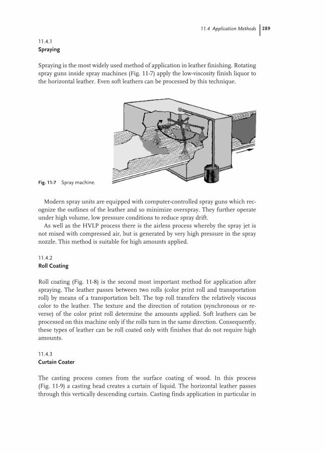
11.4 Application Methods 289
11.4.1
Spraying
Spraying is the most widely used method of application in leather finishing. Rotatingspray guns inside spray machines (Fig. 11-7) apply the low-viscosity finish liquor tothe horizontal leather. Even soft leathers can be processed by this technique.
Modern spray units are equipped with computer-controlled spray guns which rec-ognize the outlines of the leather and so minimize overspray. They further operateunder high volume, low pressure conditions to reduce spray drift.
As well as the HVLP process there is the airless process whereby the spray jet isnot mixed with compressed air, but is generated by very high pressure in the spraynozzle. This method is suitable for high amounts applied.
11.4.2
Roll Coating
Roll coating (Fig. 11-8) is the second most important method for application afterspraying. The leather passes between two rolls (color print roll and transportationroll) by means of a transportation belt. The top roll transfers the relatively viscouscolor to the leather. The texture and the direction of rotation (synchronous or re-verse) of the color print roll determine the amounts applied. Soft leathers can beprocessed on this machine only if the rolls turn in the same direction. Consequently,these types of leather can be roll coated only with finishes that do not require highamounts.
11.4.3
Curtain Coater
The casting process comes from the surface coating of wood. In this process (Fig. 11-9) a casting head creates a curtain of liquid. The horizontal leather passesthrough this vertically descending curtain. Casting finds application in particular in
Fig. 11-7 Spray machine.
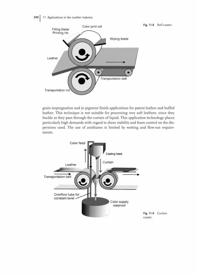
290 11 Applications in the Leather Industry
grain impregnation and in pigment finish applications for patent leather and buffedleather. This technique is not suitable for processing very soft leathers, since theybuckle as they pass through the curtain of liquid. This application technology placesparticularly high demands with regard to shear stability and foam control on the dis-persions used. The use of antifoams is limited by wetting and flow-out require-ments.
Fig. 11-8 Roll coater.
Fig. 11-9 Curtaincoater.
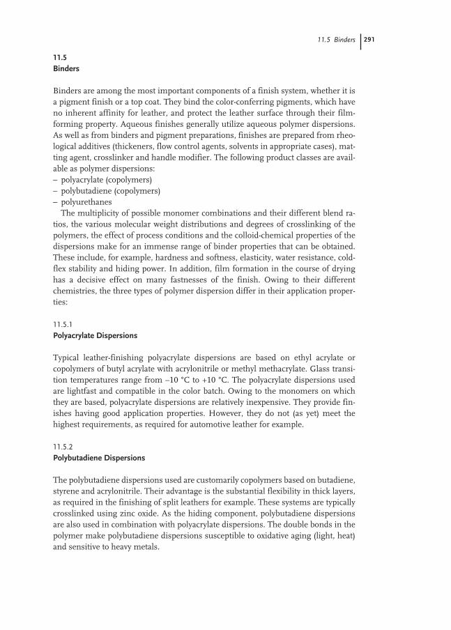
11.5 Binders 291
11.5
Binders
Binders are among the most important components of a finish system, whether it isa pigment finish or a top coat. They bind the color-conferring pigments, which haveno inherent affinity for leather, and protect the leather surface through their film-forming property. Aqueous finishes generally utilize aqueous polymer dispersions.As well as from binders and pigment preparations, finishes are prepared from rheo-logical additives (thickeners, flow control agents, solvents in appropriate cases), mat-ting agent, crosslinker and handle modifier. The following product classes are avail-able as polymer dispersions:– polyacrylate (copolymers)– polybutadiene (copolymers)– polyurethanes
The multiplicity of possible monomer combinations and their different blend ra-tios, the various molecular weight distributions and degrees of crosslinking of thepolymers, the effect of process conditions and the colloid-chemical properties of thedispersions make for an immense range of binder properties that can be obtained.These include, for example, hardness and softness, elasticity, water resistance, cold-flex stability and hiding power. In addition, film formation in the course of dryinghas a decisive effect on many fastnesses of the finish. Owing to their differentchemistries, the three types of polymer dispersion differ in their application proper-ties:
11.5.1
Polyacrylate Dispersions
Typical leather-finishing polyacrylate dispersions are based on ethyl acrylate orcopolymers of butyl acrylate with acrylonitrile or methyl methacrylate. Glass transi-tion temperatures range from –10 °C to +10 °C. The polyacrylate dispersions usedare lightfast and compatible in the color batch. Owing to the monomers on whichthey are based, polyacrylate dispersions are relatively inexpensive. They provide fin-ishes having good application properties. However, they do not (as yet) meet thehighest requirements, as required for automotive leather for example.
11.5.2
Polybutadiene Dispersions
The polybutadiene dispersions used are customarily copolymers based on butadiene,styrene and acrylonitrile. Their advantage is the substantial flexibility in thick layers,as required in the finishing of split leathers for example. These systems are typicallycrosslinked using zinc oxide. As the hiding component, polybutadiene dispersionsare also used in combination with polyacrylate dispersions. The double bonds in thepolymer make polybutadiene dispersions susceptible to oxidative aging (light, heat)and sensitive to heavy metals.

292 11 Applications in the Leather Industry
11.5.3
Polyurethane Dispersions
Polyurethanes are polyaddition compounds of isocyanates with polyols and/orNH-functional compounds. Owing to the incorporation of hydrophilic groups in thepolymer, polyurethanes form stable – usually anionically stabilized – dispersions inwater. Unlike the systems described above, polyurethane dispersions can be madewithout an emulsifier. Finishes with polyurethane dispersions are notable for a veryhigh fastness level. Flexing endurance, even at low temperatures, and rub-fastness(after crosslinking) meet the highest standards. Owing to the hydrophilic groups,polyurethane dispersions possess very good adhesion to leather. Their chemistrymakes carboxylate-stabilized systems pH-sensitive. Since monomer costs are dis-tinctly above those of the acrylates, the use of polyurethane dispersions is mainly re-stricted to applications where the special properties of polyurethane dispersions areessential.
Depending on the polyol component used, there are polyetherurethanes and poly-esterurethanes. With regard to the isocyanate component, a distinction is made be-tween aromatic and aliphatic monomers. The somewhat less costly aromatic sys-tems, however, do not meet the extreme aging resistance requirements of automo-tive leathers, for example.
11.6
Production of Selected Leather Articles
Guideline recipes for finishes for some selected leather articles will now be used byway of example to discuss the particular requirements that have to be met by thepolymer dispersions used. The finisher has to adapt these guideline recipes to theleather to be finished and to the final properties demanded (feel, appearance, fast-ness).
11.6.1
Shoe Upper Leather
In terms of area, about 60 % of all leather produced is further processed as shoe up-per leather. Shoe upper leather is the largest sector by far. Finish requirements aredictated not only by the performance characteristics but also greatly by the particularprocessing methods in the footwear industry.
In shoe making, the previously moistened leather is wiped (pulled) over the last byheated irons. The folds appearing at the round edges of the shoe are smoothed awayby heat treatment with a hot air blower or a smoothing iron (the leather shrinks atthese high temperatures). So the finish has to be heat resistant. In addition, the fin-ish must not scratch under the rubbing by the irons. The shoe sole is injection mold-ed on in a further operation. The finish coat therefore has to be solvent-fast and thedyes may not migrate into the shoe sole.

11.6 Production of Selected Leather Articles 293
Shoe upper leather requires good flexing endurance and good adhesion of the fin-ish. Rub-fastness is of minor importance.
An example of a finish recipe for shoe upper leather is:Leather type: Cattle leather box-typeBase coat: (depending on crust)Pigment finish: Pigments 100 parts
Polyacrylate dispersion (40 %) 200 partsWaxes (40 %) 50 partsCasein binder (20 %) 100 partsWater 350 parts
Top coat: Polyurethane dispersion (35 %) 400 partsWaxes (40 %) 20 partsCrosslinker (50 %) 30 partsWater 550 parts
Thickener to a 4 mm Ford cup viscosity of approximately 24 sProcessing:Pigment coat: 2 × spraying (each ca. 80 g m–2); dry
Plating: 2 s at 80 °C and 150 bar1 × spraying (ca. 50 g m–2); dry
Top coat: 2 × spraying (each ca. 50 g m–2); dry
The non-thermoplastic casein binder ensures processability in the wiping processby reducing sensitivity to heat and improving hot rub resistance. Useful top coats in-clude a nitrocellulose lacquer or an aqueous system with a very hard and hence plat-ing-fast polyurethane dispersion. If necessary, the latter can be crosslinked to im-prove the rubfastness.
11.6.2
Apparel Leather
Apparel leather is the second largest sector after shoe upper leather. It accounts forabout 20 % of leather production in terms of area.
Apparel leathers preferably utilize sheep and goat leathers, but in some cases alsocalf leather. Inevitably, fashion aspects are of primary importance with apparelleathers. Other decisive aspects are wear properties such as softness and feel. Withregard to processing, the finish does not have to meet special requirements. One im-portant performance characteristic is the light-fastness of the finish. Flexing en-durance and rub-fastness are of lesser importance.

294 11 Applications in the Leather Industry
An example of a finish recipe for apparel leather is:Leather type: SheepskinPigment coat: Pigment 50 parts
Spray dye 50 partsPolyacrylate dispersion (40 %) 200 partsWax (40 %) 100 partsWater 600 parts
Top coat: Nitrocellulose emulsion (15 %) 500 partsWax (40 %) 20 partsWater 480 parts
Processing:Pigment coat: 2 × spraying (each ca. 50 g m–2); dry
Plating: 2 seconds at 80 °C and 30 bar5 × spraying (each ca. 40 g m–2); dry
Top coat: 2 × spraying (each ca. 50 g m–2); dryHydraulic ironing: 0.5 s at 120 °C and 30 bar
Apparel leathers generally are not provided with a base coat. The pigment contentin the pigment coat has been reduced in favor of the spray dyes in order that a moretransparent, less coated appearance may be obtained for the finish. This is intensi-fied by means of low concentration of the pigment finish and the large number ofspray applications. At present, solvent-containing top coats are still customary for ap-parel leathers, but, as with shoe upper leather, there is an increasing trend towardthe use of aqueous top coats.
11.6.3
Automotive Leather
Although the amount of leather processed in the automotive sector, as leather seatsor steering wheel leather, amounts to only about 2 % in terms of area of total leatherproduction (and rising), finishing chemical demand greatly outweighs those for shoeupper leather or apparel leather, for example, because of the high fastness require-ments. These high fastness requirements in the automotive leather sector include –depending on the specific requirements of the automotive manufacturer – adhesionsof greater than 4 N cm–1, flexing endurance’s (dry, 23 °C) of 100 000 cycles and30 000 cycles at –10 °C. Similarly, rub-fastness has to meet extreme requirements:>1000 rubs wet and a swelling resistance of >2000 rubs. In addition, these leathershave to be aging resistant, i.e., they have to have adequate flexing endurance and rub-fastness even after simultaneous exposure to heat, UV light and moisture. Nor mayany color shifts occur. To achieve these very high fastnesses it is predominantly nec-essary to use polyurethane dispersions.

11.6 Production of Selected Leather Articles 295
A guideline recipe for automotive leather is:Leather type: Cattle hideBase coat: Polyurethane dispersion (20 %) 200 parts
Water 600 partsPigment coat: Pigment 100 parts
Polyurethane dispersion (35 %) 250 partsPolyacrylate dispersion (40 %) 100 partsWaxes (40 %) 80 partsMatting agent 80 partsWater 290 parts
Thickener to a 4 mm Ford cup viscosity of 16–18 sTop coat: Polyurethane dispersion (35 %) 500 parts
Waxes (40 %) 20 partsCrosslinker (50 %) 60 partsWater 420 parts
Thickener to a 4 mm Ford cup viscosity of approximately 24 sProcessing:Base coat: 1 × spraying (ca. 100 g m–2); dry
Hydraulic ironing: 2 s at 80 °C and 80 barPigment coat: 1 × spraying (70–100 g m–2); dry
Press embossing: 5 s at 80 °C and 250 bar1 × spraying (50–70 g m–2); dry
Top coat: 2 × spraying (each ca. 50 g m–2); dry
The polyurethane dispersions used in the base coat are soft and very finely divided.In contrast, the polyurethane dispersions used in the pigment coat are of mediumhardness. A portion of the polyurethane dispersions may also be replaced by poly-acrylate dispersions. These must not have an adverse effect on the cold flexing en-durance and so the polyacrylate dispersions used must have a low glass transitiontemperature. The high rub-fastnesses are primarily achieved by the crosslinking ofthe top coat. Useful crosslinkers include, for example, modified aliphatic polyiso-cyanates. The leathers are strongly embossed to conform the surface structure of theleathers to the interior styling of the car.
As an alternative to the application method described, the base and pigment coatscan also be applied by synchronous roll coating. However, for this the recipe needs tobe adjusted to a smaller water quantity and a higher color batch viscosity (about 50 sin 6 mm Ford cup).
11.6.4
Furniture Leathers
Furniture leathers, unlike automotive leathers, need less high fastnesses. Light-fast-ness is an exception. Primary furniture leather criteria are the feel properties and thevisual appearance of the leather. The use of soft polyacrylate dispersions has proved

296 11 Applications in the Leather Industry
advantageous here. The greater use of inferior leather grades increasingly forces theuse of binders that provide high covering.
An example of a recipe for furniture leather is:Leather type: Cattle hide, buffedBase coat: (depending on crust leather used)Pigment coat: Pigment 100 parts
Matting agent 80 partsWax (40 %) 80 partsPolyacrylate dispersion (40 %) 200 partsPolybutadiene dispersion (40 %) 100 partsWater 290 parts
Thickener to a 4 mm Ford cup viscosity of 16–18 sTop coat: Polyurethane dispersion (35 %) 400 parts
Waxes (40 %) 50 partsCrosslinker (50 %) 30 partsWater 520 parts
Thickener to a 4 mm Ford cup viscosity of 24 sProcessing:Pigment coat: 2 × spraying (each ca. 80 g m–2); dry
Embossing: 3 s at 80 °C and 150 bar1 × spraying (ca. 50 g m–2); dry
Top coat: 1 × spraying (ca. 50 g m–2); dryHydraulic ironing: 0.5 s at 120 °C and 30 bar
The requisite hiding performance is achieved through the partial use of thepolybutadiene dispersion. Furniture leathers are softer than automotive leathers.Embossing is accordingly done under less pressure. Since the fastness requirementsare lower, the top coat is less crosslinked and the applied amount is lower. For aes-thetic reasons, the leather is briefly plated after the application of the top coat.
11.7
Test Methods in Leather Finishing
The primary purpose of the test methods is to ensure that the finished leathers are asa whole suitable for the stated purpose. Accordingly, many test methods simulate thestresses to which the finished leathers are exposed in use. It must always be noted inthis context that the leather itself has a substantial influence on the tests as well asthe finish coat on the leather. The different leather types vary greatly in thickness,softness, surface structure, hydrophilicity, etc. Even a single hide is not homoge-neous in itself. For example, fiber density, leather thickness, pore structure and ab-sorbency are different in the belly than in the butt. For this reason, the correspon-ding test descriptions (e.g., DIN or ISO standards) provide precise definitions of theareas of the leather from which the test specimens are to be taken. The test results

11.7 Test Methods in Leather Finishing 297
depend not only on the sampling position but also on the moisture content of theleather specimens. The drier the leather is, the harder and less elastic are the leatherfibers. For this reason, the test methods prescribe that the test specimens must beconditioned under standard atmospheric conditions (e.g., 50 % relative humidityand 23 °C or 65 % and 20 °C).
Since finished leathers are predominantly used in the shoe industry, test methodsare largely adapted to these requirements. From experience, these test methods arealso suitable for evaluating other leather articles such as upholstery leather, apparelleather and leather for bags and suitcases. The fastness level to be achieved variesfrom article to article.
The International Union of Leather Technologists’ and Chemists’ Societies has de-veloped, mostly binding, “Methods of chemical leather analysis” (I.U.C. methods)and “Methods of physical leather testing” (I.U.P. methods). The German DIN sheetsfor testing leather have in most cases been conformed to the above methods. I.U.F.(International Union Fastness) describes guidelines and test methods drawn up bythe International Fastness Commission for leather dyes and dyed leathers.
The following methods are only the most important tests in common use. In addi-tion, there are a multiplicity of specific test methods, either designed for certainleather articles or required by certain customers.
11.7.1
Flexing Endurance
This test describes the behavior of the finish coat on repeated flexing of the leather.It is among the most important tests of the finish.
The test is carried out both on dry and on wet leathers. It is described inDIN 53351 or I.U.P. 20. The rectangular leather specimens are clamped into a flex-ometer (Bally flexometer, Fig. 11-10) with a fold. The rotational movement of the up-
Fig. 11-10 Bally flexometer.

298 11 Applications in the Leather Industry
per axis makes the fold move back and forth on the surface of the leather. The finishis assessed after 1000, 5000, 10 000, 20 000, 35 000, 50 000 flexes. For particularly de-manding requirements, the test is continued to 100 000 flexes. Wet specimens areflexed only 20 000 times at most. Any more will dry the leather too much.
After visual examination, the test specimen is evaluated according to the degree ofdamage of the finish coat.
High flexibility is demanded, for example, by the shoe industry for work andsports footwear. But leathers for the automotive sector (e.g., leather seats) also haveto meet such high requirements.
A variation of this test is flexing endurance at temperatures below freezing. Typi-cal requirements are 30 000 flexes at –10 °C or 10 000 flexes at –20 °C.
11.7.2
Rub-fastness
The rub-fastness test examines resistance of the pigment coat to abrasion and thetransfer of color to other surfaces (crocking). The test is carried out on the VESLICrub-fastness tester (Fig. 11-11). This test is governed by the standards DIN 53339 andI.U.F. 450.
On a stretched leather a felt is rubbed back and forth. The felt is 10 mm × 10 mmin size and weighted with 1 kg. The leather is stretched 10 %. The test is customarilycarried out in three variations:
Dry rub-fastness: dry leather, dry feltWet rub-fastness: dry leather, wet feltSwelling resistance: wet leather, dry felt
The damage or change in the finish coat and the transfer of color to the rubbingelement are assessed after fixed rubbing intervals. This method provides data on thesensitivity of the finished leather surface to rubbing through, abrasion or transfer ofcolor from the pigment coat under both dry and moist conditions.
Rub-fastnesses are also tested using the SATRA rub-fastness tester. In this test a rotating pad of felt acts on the leather surface under a certain pressure and at adefined speed of rotation. The leather is evaluated after fixed numbers of cycles. Thistest is likewise carried out with both a dry and a wet felt pad.
Fig. 11-11 VESLIC rubfastness tester.

11.7 Test Methods in Leather Finishing 299
As a further variation, the test can be carried out under exposure to various,defined test liquids: perspiration rub-fastness, chemical rub-fastness, etc.
11.7.3
Dry and Wet Adhesion
This test determines the adhesion of the finish coat to the leather surface. It also pro-vides evidence of possible inter-adhesion problems within the finish coat. Thesearise in particular when excessive auxiliary quantities (especially waxes) are used orthe crosslinking of the preceding layer is excessive. Ideally, the adhesion of the finishto the leather is such that, in this test, the finish can only be pulled off together withthe grain layer.
Strips of leather having a certain length and width are glued to a fixed basis using a defined adhesive. The tensile tester is then used to pull this leather awayfrom the basis at an angle of 90°. The force measured during the pulling is recordedand its average reported. This test is repeated at least four times with half the testspecimens being punched out along the backbone and the other half at right anglesto it.
To test the wet adhesion, the adhered specimens are immersed in water and testedafter a predetermined time.
11.7.4
Fastness to Ironing
This test is important for finished shoe upper leathers (see above) in particular. Aniron is moved once back and forth across the leather surface over a slightly roundededge as a preliminary test. The damage to the finish and any shift in hue are thenevaluated. The test temperatures are increased in intervals of 20 °C. A more sensitiveversion of this test is carried out on the VESLIC rub-fastness tester using a heatabletest punch. Again the temperatures are increased in intervals of 20 °C. The result isassessed in each case after five rubs.
11.7.5
Hot Air Fastness
In this test, which is likewise important for shoe leathers, the leather samples aresubjected for 1 min to the flow of hot air from a hair dryer (150 °C). The damage tothe finish and the change in hue are then assessed.
11.7.6
Aging resistance
The leather specimens are aged (a) at 50 °C for 7 days or (b) at 80 °C for 3 days. Theyare then assessed to see whether heat aging has resulted in embrittlement, yellowingor a change in the flexing endurance.

300 11 Applications in the Leather Industry
11.7.7
Fogging test
This test, which is important for automotive leathers in particular, determines thecondensation on cooled glass panes of volatiles from the leather or the finish coat. Itis described in DIN 75201. There are two different methods of measurement: (a) thereflectometric method and (b) the gravimetric method. While the gravimetricmethod indicates the condensed mass, for example after 16 h at 100 °C, the reflecto-metric method describes the clouding of the cooled glass plate after 3 h at 100 °C.
11.7.8
Light-fastness
The test is carried out using not only daylight (I.U.F. 401) but also artificial light(xenon lamp) (I.U.F. 402). The leather strip to be tested is exposed to the light to-gether with a light-fastness scale. The light-fastness scale is made up of eight coloredcotton strips having different, defined light-fastness. The color change of the leatheris compared with the color change of the light-fastness scale.
11.7.9
Hot light aging
This test is important for automotive leather in particular. It assesses the effect oflight, heat and moisture on the flexing endurance, the rub-fastness and the colorfastness of the leather finish. Finished leather strips are exposed to a defined dose ofradiation in a test chamber at 20 % relative humidity. The color fastness is examinedafter the first cycle, the flexing endurance after the second cycle, the rub-fastness af-ter the third cycle and the color fastness once more after the last cycle. Requirementsdiffer from one car producer to the other.
References
1 Stather, F., Gerbereichemie und Gerberei-technologie, Akademie Verlag, Berlin,1967.
2 Schubert, R., in: Herfeld, H. (Ed.) Biblio-thek des Leders, Vol. 6; Lederzurichtung,Oberflächenbehandlung des Leders, Um-schau Verlag, Frankfurt am Main, 1982.
3 Heidemann, E., Ullmanns Enzyklopädieder technischen Chemie, Vol. A15(Leather), Verlag Chemie, Weinheim.
4 Schubert, R., in: Kittel, H. (Ed.) Lehrbuchder Lacke und Beschichtungen, Vol. 5, W. A. Colomb. Heenemann Verlags-gesellschaft, Berlin, 1977.
5 Science and Technology for Leather into the next Millennium, Proc. XXVIULTCS Congress, 1999, Tata McGraw-Hill, New Delhi, 1999.
6 Wood, G., Osgood, M., Leather Finish-ing, in Leather Technologists Pocket Book,The Society of Leather Technologistsand Chemists, 1999, Chapter 9.
7 Heidemann, E., Fundamentals ofLeather Manufacturing, EduardRoetherdruck, Darmstadt, 1993, and references cited therein.

301
12
Applications for Asphalt Modification
Koichi Takamura
12.1
Introduction
The annual worldwide consumption of asphalt was over 90 000 000 metric tons in1995 and the US used approximately one-third of that total [1]. The global asphaltconsumption in 1996 is represented in Fig. 12-1 [2]. Greater than 85 % of 30 000 000metric tons consumed in USA was used to maintain and improve more than3 000 000 km (2 000 000 miles) of asphalt roads (Fig. 12-2) with an annual road bud-get of $85 billion [2]. Federal Highway Trust Fund Authorizations reached nearly$21 billion in 1996. There are more than 6 000 000 km (4 000 000 miles) of roads, andasphalt roads account for 94 % (3 270 000 km) of the paved roads in the US. The oth-er 6 % (200 000 km) are paved with Portland cement concrete, which is primarilyused for the heavy traffic area of the interstate highway [1].
Asphalt production is not very uniform throughout the US. The Midwest has thehighest production (40 %), followed by the Gulf Coast (25 %), the East Coast (17 %),the West Coast (11 %), and the Rocky Mountains.
Over 90 % (16 % of total asphalt consumption as in Fig. 12-2) asphalt used in theUS for non-paving purposes is sold to the roofing industry. Two thirds of that is con-
Fig. 12-1 The annual global asphaltconsumption. North America andEurope consume two-thirds of total90 000 000 tons.
Global Asphalt Consumption
Europe
Asia/Australia
North America
Others

302 12 Applications for Asphalt Modification
sumed in the manufacture of shingles for houses, and the other third is used in com-mercial built-up roof.
Almost 90 % of US paving asphalt consumption is for hot mix. The remaining10 % of the paving asphalt usage (approximately 7 % of the total asphalt consump-tion) is comprised of asphalt emulsions, primarily used for preventive maintenance andrehabilitation techniques such as chip seal, slurry seal and microsurfacing. Emulsi-fied asphalts are also used for construction in recycling of old paving materials.
The use of polymer modified asphalts for hot mix and asphalt emulsions hasgrown significantly in the US during the last 10 years. The National Center for As-phalt Technology (NCAT) has published a list of reasons for the use of asphalt mod-ification [3, 4]. Asphalt has been modified to:– stiffen binders and mixtures at high temperatures to minimize rutting and reduce
the detrimental effects of load induced moisture damage– soften binders at low temperatures to improve relaxation properties and strain tol-
erance, thus minimizing non-load associated thermal cracking– improve fatigue resistance, particularly in environments where higher strains are
imposed on the asphalt concrete mixture– improve asphalt–aggregate bonding to reduce stripping,– reduce raveling by improving abrasion resistance,– minimize tender mixes, drain-down, or segregation during construction,– rejuvenate aged asphalt binders,– replace asphalt cement as an extender,– permit thicker films of asphalt on open-graded aggregates for increased durability,– reduce flushing or bleeding,– improve resistance to aging or oxidation,– stiffen hot mix asphalt (HMA) layers to reduce required structural thickness,– improve pavement durability with an accompanying net reduction in life cycle
costs,– replace Portland cement concrete with asphalt construction methods that reduce
lane closure times and user delay costs, and– improve overall performance as viewed by the highway user.
Fig. 12-2 Use of asphalt in the US.Others
Roofings
Emulsions forPaving
AsphaltCement for
Paving

12.2 Hot Mix Asphalt Paving 303
According to the article by King et al. [3], patents for modifying asphalt with natu-ral and synthetic polymers were granted as early as 1843 [5]. The polymers are addedto alleviate pavement problems and to realize economic, environmental, energy, ap-plication and/or performance benefits. Test projects were placed in Europe begin-ning in the 1930s [6]. In North America, neoprene latex was introduced in the 1950sand found a small but steady market, primarily in Canada and the Western UnitedStates [7]. Natural rubber latex, one of the materials mentioned in the earliestpatents, is still being used today, primarily in water-based emulsion applicationssuch as microsurfacing. Neoprene modified asphalts have been used for many years,but have more recently been replaced by other types of elastomeric polymers such asstyrene-butadiene-styrene, SBS block co-polymers. Water based styrene-butadienerubber (SBR) latex has found wide usage as an additive to asphalt emulsions to im-prove chip retention. The introduction of polymers into asphalt emulsions allowsthem now to be successfully used for almost any paving application. Recent empha-sis on sustainable development and the concern about global warming has encour-aged further development of cold paving technology using asphalt emulsions. As-phalt emulsions for paving already account for more than 40 % of total asphalt con-sumption in France and nearly 30 % in Spain [2].
Polymer modified asphalt accounts for less than 10 % of total asphalt consump-tion for paving in the US, thus corresponding to approximately 3 000 000 metric tonsa year in the US. The polymer content in these modified asphalt is, on average, 3 %by weight, resulting in less than 100 000 metric tons of polymers being used for thisapplication. Although the exact figure is not available, the synthetic and natural lat-tices account for approximately 30 % of the total polymer annually consumed in theUnited States. Approximately 1 000 000 metric tons of polymer modified asphaltwere used in Europe in 1996 and 70 % of these are modified with elastomeric polymers.
12.2
Hot Mix Asphalt Paving
Hot mix paving and cold paving with asphalt emulsion are the two types of pavingtechnologies used for producing asphalt-based pavements [3]. In hot mix paving,aggregates are heated to a temperature above 200 °C to remove residual water andmixed with molten asphalt, which is at a temperature as high as 160–180 °C [3, 8].The aggregate-asphalt mixture is then transported to the job site, spread and com-pacted. The mix has to be sufficiently hot to be compacted adequately within thespecified density. In general, the job site has to be within a 1-h transportation dis-tance from the mix plant. Because of the need for the aggregate and the asphalt to beat high temperatures, there are considerable energy requirements and cost associat-ed with the hot mix process. In fact heating aggregates accounts for nearly 90 % ofthe total energy usage of hot mix paving.
The typical cold paving method includes mixing aggregates with asphalt emulsionand thus it does not involve heating the components used to produce the asphalt-based formulation. Asphalt emulsions will be discussed in Sect. 12.3.

304 12 Applications for Asphalt Modification
12.2.1
Asphalt Specification
Asphalt used for paving has been graded with regards to its viscosity at 60 °C (140 °F)conforming to American Association of State Highways and Transportation Offi-cials, AASHTO M226 specifications, or 25 °C (77 °F) penetration graded asphalt con-forming to AASHTO M20. These specifications are based on properties at one spec-ified temperature and do not necessarily predict asphalt performance over the widerange of climatic conditions that the pavement is subjected to in its lifetime.
Changes in crude sources and refinery processes caused deterioration of pave-ments during the energy crisis in the late 1970s to early 1980s. The problem was rec-ognized by the Federal government and led to the development of the StrategicHighway Research Program (SHRP) to examine the entire paving technology forboth Portland cement and asphalt based pavements. For asphalt paving technology,these studies included the entire road construction procedure, aggregate specifica-tion and compaction method. The study also defined the laboratory testing proce-dures and specifications for both the asphalt-aggregate mix, (such as a compactionmethod for core sample preparation), rutting, fatigue and cold fracture testing of pre-pared samples. The SHRP study also developed Superpave® Performance Graded(PG) asphalt binder specifications based on the pavement’s temperature range [3, 4, 8].
The specification is based on the rutting, fatigue and cold fracture resistance of theasphalt binder and defined by two numerical values representing the upper and low-er temperature limits of particular asphalt in °C (e.g. PG64-22). The asphalt binderbecomes too fluid during hot summer days under strong sun resulting in permanentdeformation, which is called rutting. In contrast, the binder becomes brittle duringcold winter nights. A perpendicular crack across the pavement lane develops whenthe stress generated by thermal contraction exceeds a critical value. The freshlyapplied pavement is most susceptible to rutting, but it becomes more susceptible tofatigue fracture when the asphalt binder is oxidized and loses its flexibility duringusage. Therefore, rutting and fatigue resistances are based on the fresh asphalt andafter the rotating thin film oven test, RTFOT. This test simulates asphalt heat agingduring the hot mix process. Cold characterization is based on the asphalt binder afterthe pressurized aging vessel, PAV, test which is intended to reproduce 7–10 years ofoxidative aging of the asphalt binder on the road.
All Superpave specifications are based on the SI unit, emphasizing importance ofinternational recognition. The World Road Association (PIARC) in France has beenactive in developing similar international specifications [9, 10].
PG GradingThe Superpave asphalt mix design system includes the performance grade (PG) as-phalt binder specification. The Superpave asphalt binder tests try to determine phys-ical properties that can be directly related to field performance in terms of rutting,fatigue cracking and low temperature cracking. Superpave characterizes asphalt atthe actual pavement temperatures it will experience, and at the periods of time whendistresses are most likely to occur. A part of the Superpave binder specification is

12.2 Hot Mix Asphalt Paving 305
shown in Tab. 12-1. Detailed specifications as well as test apparatus, procedures andthe PG specification can be found elsewhere [8, 11].
Tab. 12-1 Example of Superpave binder specification.
Performance grade PG64 PG70
–10 –16 –22 –28 –34 –40 –10 –16 –22 –28 –34 –40
Average 7-day maximum pavement design temperature (°C) <64 <70
Minimum pavement design temperature (°C) >–10 >–16 >–22 >–28 >–34 >–40 >–10 >–16 >–22 >–28 >–34 >–40
Original binderFlash-point temp., minimum (°C) 230
Viscosity maximum 3 Pa s, test temp. (°C) 135
Dynamic shear, G*/sin(δ), minimum 1.00 kPa, test temp. at 10 rad s–1 (°C) 64 70
Rolling thin film oven residueMass loss, maximum, % 1.00
Dynamic shear, G*/sin(δ ), minimum 2.30 kPa, test temp. at 10 rad s–1 (°C) 64 70
Pressure aging vessel residuePAV aging temperature (°C) 100 100 (110)*
Dynamic shear, G*sin(δ ), minimum 5.00 MPa, test temp. at 10 rad s–1 (°C) 31 28 25 22 19 16 34 31 28 25 22 19
Creep stiffness, S, maximum, 300 MPa, m-value minimum, 0.300, Test temp., at 60 s (°C) 0 –61 –12 –18 –24 –30 0 –6 –12 –18 –24 –30
*110 °C PAV for the desert climate
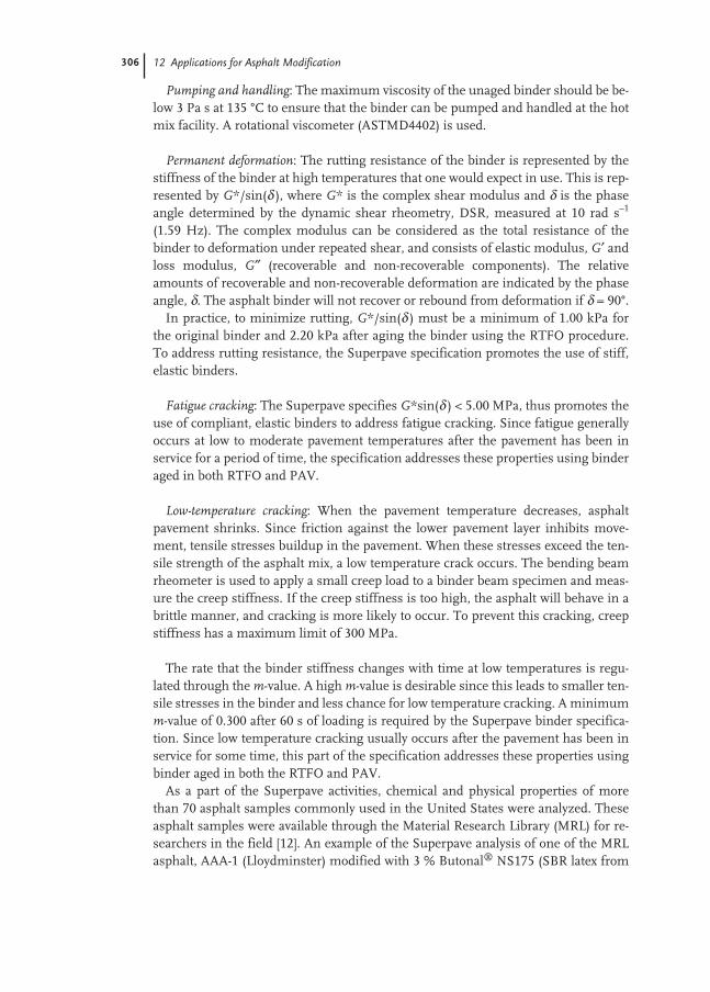
306 12 Applications for Asphalt Modification
Pumping and handling: The maximum viscosity of the unaged binder should be be-low 3 Pa s at 135 °C to ensure that the binder can be pumped and handled at the hotmix facility. A rotational viscometer (ASTMD4402) is used.
Permanent deformation: The rutting resistance of the binder is represented by thestiffness of the binder at high temperatures that one would expect in use. This is rep-resented by G*/sin(δ ), where G* is the complex shear modulus and δ is the phaseangle determined by the dynamic shear rheometry, DSR, measured at 10 rad s–1
(1.59 Hz). The complex modulus can be considered as the total resistance of thebinder to deformation under repeated shear, and consists of elastic modulus, G′ andloss modulus, G″ (recoverable and non-recoverable components). The relativeamounts of recoverable and non-recoverable deformation are indicated by the phaseangle, δ. The asphalt binder will not recover or rebound from deformation if δ = 90°.
In practice, to minimize rutting, G*/sin(δ ) must be a minimum of 1.00 kPa forthe original binder and 2.20 kPa after aging the binder using the RTFO procedure.To address rutting resistance, the Superpave specification promotes the use of stiff,elastic binders.
Fatigue cracking: The Superpave specifies G*sin(δ ) < 5.00 MPa, thus promotes theuse of compliant, elastic binders to address fatigue cracking. Since fatigue generallyoccurs at low to moderate pavement temperatures after the pavement has been inservice for a period of time, the specification addresses these properties using binderaged in both RTFO and PAV.
Low-temperature cracking: When the pavement temperature decreases, asphaltpavement shrinks. Since friction against the lower pavement layer inhibits move-ment, tensile stresses buildup in the pavement. When these stresses exceed the ten-sile strength of the asphalt mix, a low temperature crack occurs. The bending beamrheometer is used to apply a small creep load to a binder beam specimen and meas-ure the creep stiffness. If the creep stiffness is too high, the asphalt will behave in abrittle manner, and cracking is more likely to occur. To prevent this cracking, creepstiffness has a maximum limit of 300 MPa.
The rate that the binder stiffness changes with time at low temperatures is regu-lated through the m-value. A high m-value is desirable since this leads to smaller ten-sile stresses in the binder and less chance for low temperature cracking. A minimumm-value of 0.300 after 60 s of loading is required by the Superpave binder specifica-tion. Since low temperature cracking usually occurs after the pavement has been inservice for some time, this part of the specification addresses these properties usingbinder aged in both the RTFO and PAV.
As a part of the Superpave activities, chemical and physical properties of morethan 70 asphalt samples commonly used in the United States were analyzed. Theseasphalt samples were available through the Material Research Library (MRL) for re-searchers in the field [12]. An example of the Superpave analysis of one of the MRLasphalt, AAA-1 (Lloydminster) modified with 3 % Butonal® NS175 (SBR latex from
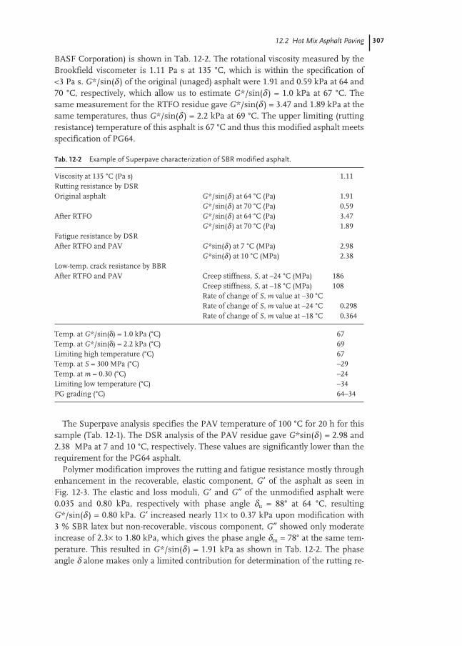
12.2 Hot Mix Asphalt Paving 307
BASF Corporation) is shown in Tab. 12-2. The rotational viscosity measured by theBrookfield viscometer is 1.11 Pa s at 135 °C, which is within the specification of<3 Pa s. G*/sin(δ ) of the original (unaged) asphalt were 1.91 and 0.59 kPa at 64 and70 °C, respectively, which allow us to estimate G*/sin(δ ) = 1.0 kPa at 67 °C. Thesame measurement for the RTFO residue gave G*/sin(δ ) = 3.47 and 1.89 kPa at thesame temperatures, thus G*/sin(δ ) = 2.2 kPa at 69 °C. The upper limiting (ruttingresistance) temperature of this asphalt is 67 °C and thus this modified asphalt meetsspecification of PG64.
The Superpave analysis specifies the PAV temperature of 100 °C for 20 h for thissample (Tab. 12-1). The DSR analysis of the PAV residue gave G*sin(δ ) = 2.98 and2.38 MPa at 7 and 10 °C, respectively. These values are significantly lower than therequirement for the PG64 asphalt.
Polymer modification improves the rutting and fatigue resistance mostly throughenhancement in the recoverable, elastic component, G′ of the asphalt as seen inFig. 12-3. The elastic and loss moduli, G′ and G″ of the unmodified asphalt were0.035 and 0.80 kPa, respectively with phase angle δu = 88° at 64 °C, resultingG*/sin(δ ) = 0.80 kPa. G′ increased nearly 11× to 0.37 kPa upon modification with3 % SBR latex but non-recoverable, viscous component, G″ showed only moderateincrease of 2.3× to 1.80 kPa, which gives the phase angle δm = 78° at the same tem-perature. This resulted in G*/sin(δ ) = 1.91 kPa as shown in Tab. 12-2. The phaseangle δ alone makes only a limited contribution for determination of the rutting re-
Tab. 12-2 Example of Superpave characterization of SBR modified asphalt.
Viscosity at 135 °C (Pa s) 1.11Rutting resistance by DSROriginal asphalt G*/sin(δ ) at 64 °C (Pa) 1.91
G*/sin(δ ) at 70 °C (Pa) 0.59After RTFO G*/sin(δ ) at 64 °C (Pa) 3.47
G*/sin(δ ) at 70 °C (Pa) 1.89Fatigue resistance by DSRAfter RTFO and PAV G*sin(δ ) at 7 °C (MPa) 2.98
G*sin(δ ) at 10 °C (MPa) 2.38Low-temp. crack resistance by BBRAfter RTFO and PAV Creep stiffness, S, at –24 °C (MPa) 186
Creep stiffness, S, at –18 °C (MPa) 108Rate of change of S, m value at –30 °CRate of change of S, m value at –24 °C 0.298Rate of change of S, m value at –18 °C 0.364
Temp. at G*/sin(δ) = 1.0 kPa (°C) 67Temp. at G*/sin(δ) = 2.2 kPa (°C) 69Limiting high temperature (°C) 67Temp. at S = 300 MPa (°C) –29Temp. at m = 0.30 (°C) –24Limiting low temperature (°C) –34PG grading (°C) 64–34

308 12 Applications for Asphalt Modification
sistance since sin(δ ) = 0.999 and 0.981 at δu = 88° and δm = 78°, respectively, for theunmodified and modified asphalt.
The bending beam rheometry (BBR) of the PAV residue was conducted to estab-lish the low limiting temperature of the modified asphalt. The creep stiffness valueswere 186 and 108 MPa, and the m-values were 0.298 and 0.364 determined at –24and –18 °C, respectively (Tab. 12-2). Thus, S would be 300 MPa about at –29 °C andm would be 0.300 at approximately –24 °C. Taking the higher value, –24 °C is the lowtemperature limit of this asphalt determined at a condition of 60-s loading.
The desired value of creep stiffness was originally developed as a correlation be-tween thermal cracking of in-service asphalt pavement and binder stiffness valuesestimated at 2 h loading time. However, using the concept of time–temperature su-perposition, it was confirmed that by raising the test temperature 10 °C, equal creepstiffness could be obtained after a 60-s loading. Thus, –34 °C would be the low tem-perature limit from the BBR measurement. We conclude that this asphalt meets thePG64-34 specifications as shown in Tab. 12-1.
Improvement in both the rutting and cold fracture resistance of the asphalt withthe polymer modification are demonstrated in Tab. 12-3 where Superpave analysis ofunmodified and modified with 3 % Butonal NS175 for AAA-1 and AAK-1 (Boscan)asphalt are compared. In addition to the Superpave analysis, values of conventionalmeasures of unmodified and modified asphalt, such as ductility (ASTM D113), pen-etration (ASTM D5), softening point (ASTM D36) and absolute viscosity measured at60 °C (ASTM D2171) are also included.
Fig. 12-3 Complex modulus G* ofunmodified and 3 % SBR latex modi-fied asphalt measured at 64 °C. Thepolymer modification results in 11×increase in the elastic component, G′with moderate increase in viscouscomponent, G″.
0.01
0.1
1
10
0.01 0.1 1
G' (Elastic Behavior), kPa
G"
(Vis
cou
s B
ehav
ior)
, kP
a
δδ u
Unmodified
SBR Modified
G*
G*
δδ m

12.2 Hot Mix Asphalt Paving 309
The results of modifying asphalt with additives are highly dependent upon theconcentration, the molecular mass, the chemical composition, and microscopic mor-phology of the additive as well as the crude source, the refining process and the gradeof the base asphalt used.
Superpave binder specifications are successful in predicting the rutting resistanceand cold fracture resistance of the unmodified asphalt. A new DSR procedure is un-der development for the better prediction of fatigue resistance. Integration of thebending beam rheometry data and direct tension measurement in the near futurewill provide a better description of the benefits of the polymer-modified asphalt.
One of the primary benefits of polymer modified asphalt binders is a reduced sus-ceptibility to temperature variation [13]. Because many Performance Grade asphaltspecifications can only be met with polymer modification, it is expected that the useof polymer modified binders will increase as these specifications are implementedduring the late 1990s and the early 2000s. A 1997 survey of state highway agenciesfound that 35 agencies reported that they will be using greater quantities of modifiedbinders; 12 agencies reported they will be using the same amount of modifiedbinders; and no agency reported they will be using less modified binder [14].
Storage StabilityA polymer-modified asphalt is a two phase system, forming a continuous fine poly-mer network, that is highly swollen with aromatic components in the asphalt. Thepolymer is mixed in the asphalt and stored at elevated temperature, which couldcause chemical reaction within polymer chains and with some components in the as-phalt. The degree of swelling, and thus the microscopic morphology of the polymerphase, varies widely dependent on the crude source, the refining process and thegrade of the base asphalt [15–17].
Tab. 12-3 Superpave analysis of unmodified and SBR modified asphalts.
Asphalt AAA-1 AAK-1Properties
Unmodified Modified Unmodified Modified
Brookfield viscosity at 135 °C (mPa s) 280 1100 560 2000Temp. at G*sin(δ) = 1 kPa (°C) 58 67 63 79Temp. at G*–sin(δ) = 2.2 kPa after RTFO (°C) 58 69 65 78Temp. at S = 300 MPa (°C) –21 –29 –14 –19Temp at m = 0.30 (°C) –24 –24 –17 –14Limiting high temperature (°C) 58 67 63 78Limiting low temperature (°C) –31 –34 –24 –24PG Grading 58–28 64–34 64–22 76–22Ductility at 4 °C >150 >150 28 86Penetration (mm) at 25 °C 16 11 6.7 4.5Softening Point (°C) 44 56 49 63Absolute viscosity at 60 °C (Pa s) 0.086 0.34 0.33 1.6

310 12 Applications for Asphalt Modification
When the chemical and physical properties of the polymer and asphalt are notmatched to each other, a polymer rich phase could develop near the surface of theasphalt when stored at 160–170 °C for a few days without agitation as reported byBrûlé et al. with SBS modified asphalts [16]. The asphalt composition in the polymerrich phase is vastly different from the original asphalt.
One of their results with Asphalt E modified with 5 % SBS polymer is shown inFig. 12-4. The aromatic and saturate components preferentially partition to the poly-mer phase, thus concentrating the asphaltenes and polar resin fractions in the as-phalt phase. The majority of asphaltenes are retained in the asphalt phase, resultingin an increase in the asphaltenes/aromatic ratio. This potentially leads to reducedswelling of asphaltenes, which would have negative effects on low temperature flexi-bility of asphalt.
The phase separation during storage can be visualized with hot stage optical mi-croscopy, which allows us to observe changes in the polymer morphology at the mix-ing and storage conditions. Here, the other MRL asphalt, AAB-1 (Wyoning Sour),was modified with 3 % Butonal NS175. Photomicrographs shown in Fig. 12-5 illus-trate the presence of a fine polymer network in the freshly mixed sample observed at110 °C at ×200 magnification. The polymer phase transfers to macroscopic polymerglobules without agitation when the sample is slowly heated to 170 °C. These poly-mer blobs migrate to the top due to the density difference.
Fig. 12-4 Difference in asphalt composition among original asphalt andthe polymer rich and asphalt phases developed during storage.
Original Asphalt E
Aromatic
Resin
Asphaltene
Saturate
Asphalt phase
Polymer phase
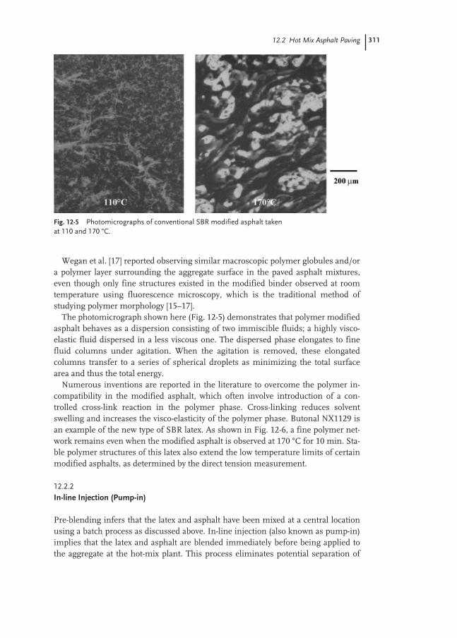
12.2 Hot Mix Asphalt Paving 311
Wegan et al. [17] reported observing similar macroscopic polymer globules and/ora polymer layer surrounding the aggregate surface in the paved asphalt mixtures,even though only fine structures existed in the modified binder observed at roomtemperature using fluorescence microscopy, which is the traditional method ofstudying polymer morphology [15–17].
The photomicrograph shown here (Fig. 12-5) demonstrates that polymer modifiedasphalt behaves as a dispersion consisting of two immiscible fluids; a highly visco-elastic fluid dispersed in a less viscous one. The dispersed phase elongates to finefluid columns under agitation. When the agitation is removed, these elongatedcolumns transfer to a series of spherical droplets as minimizing the total surfacearea and thus the total energy.
Numerous inventions are reported in the literature to overcome the polymer in-compatibility in the modified asphalt, which often involve introduction of a con-trolled cross-link reaction in the polymer phase. Cross-linking reduces solventswelling and increases the visco-elasticity of the polymer phase. Butonal NX1129 isan example of the new type of SBR latex. As shown in Fig. 12-6, a fine polymer net-work remains even when the modified asphalt is observed at 170 °C for 10 min. Sta-ble polymer structures of this latex also extend the low temperature limits of certainmodified asphalts, as determined by the direct tension measurement.
12.2.2
In-line Injection (Pump-in)
Pre-blending infers that the latex and asphalt have been mixed at a central locationusing a batch process as discussed above. In-line injection (also known as pump-in)implies that the latex and asphalt are blended immediately before being applied tothe aggregate at the hot-mix plant. This process eliminates potential separation of
Fig. 12-5 Photomicrographs of conventional SBR modified asphalt takenat 110 and 170 °C.
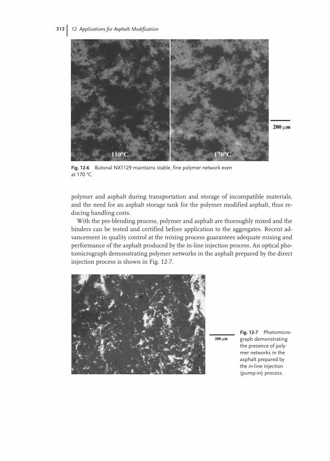
312 12 Applications for Asphalt Modification
polymer and asphalt during transportation and storage of incompatible materials,and the need for an asphalt storage tank for the polymer modified asphalt, thus re-ducing handling costs.
With the pre-blending process, polymer and asphalt are thoroughly mixed and thebinders can be tested and certified before application to the aggregates. Recent ad-vancement in quality control at the mixing process guarantees adequate mixing andperformance of the asphalt produced by the in-line injection process. An optical pho-tomicrograph demonstrating polymer networks in the asphalt prepared by the directinjection process is shown in Fig. 12-7.
Fig. 12-6 Butonal NX1129 maintains stable, fine polymer network even at 170 °C.
Fig. 12-7 Photomicro-graph demonstratingthe presence of poly-mer networks in theasphalt prepared bythe in-line injection(pump-in) process.

12.3 Paving with Asphalt Emulsion 313
12.3
Paving with Asphalt Emulsion
Asphalt emulsions used in road construction and maintenance are either anionic orcationic, based on the electrical charge of the asphalt particles, which is determinedby the type of the emulsifying agent used. The asphalt contents of these emulsionsare, in most cases, from 55 to 75 % and prepared using a high shear mechanical de-vice such as a colloid mill. The colloid mill has a high-speed rotor that revolves at1000–6000 rpm with mill-clearance settings in the range of 0.2 to 0.5 mm. A typicalasphalt emulsion has a mean particle size of 2–5 µm in diameter with distributionfrom 0.3 to 20 µm. A photomicrograph and typical size distribution of an asphaltemulsion are shown in Fig. 12-8. Asphalt emulsion properties depend greatly uponthe emulsifier used for their preparation.
A latex modified asphalt emulsion can be prepared using several methods: addi-tion of the latex in the aqueous emulsifier solution, direct injection in the asphaltline just ahead of the colloid mill or post-addition to the pre-manufactured emulsion,as schematically shown in Fig. 12-9. Addition to the aqueous phase is the most com-monly used method. The direct injection process often helps to produce an emulsionwith a desired high viscosity for chip seal application (Sect. 12.3.1). This is due to thenarrow particle size distribution of the asphalt emulsion produced with this process.
Asphalt emulsions are classified with their charge and on the basis of how quicklythe asphalt will coalesce, which is commonly referred to as breaking, or setting. Theterms RS, MS and SS have been adopted to simplify and standardize this classifica-tion. They are relative terms only and mean rapid-setting, medium-setting and slow-setting. An RS emulsion has little or no ability to mix with an aggregate, an MSemulsion is expected to mix with coarse but not fine aggregate, and an SS emulsionis designed to mix with fine aggregate. The emulsions are further subdivided by a se-ries of numbers and letters related to the viscosity of the emulsions and the hardnessof the base asphalt cements. The letter “C” in front of the emulsion type denotes
Fig. 12-8 Particle size distribution and photomicrograph of a typicalasphalt emulsion.
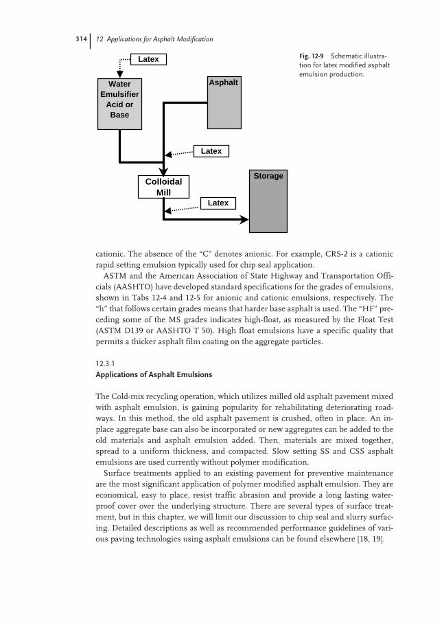
314 12 Applications for Asphalt Modification
cationic. The absence of the “C” denotes anionic. For example, CRS-2 is a cationicrapid setting emulsion typically used for chip seal application.
ASTM and the American Association of State Highway and Transportation Offi-cials (AASHTO) have developed standard specifications for the grades of emulsions,shown in Tabs 12-4 and 12-5 for anionic and cationic emulsions, respectively. The“h” that follows certain grades means that harder base asphalt is used. The “HF” pre-ceding some of the MS grades indicates high-float, as measured by the Float Test(ASTM D139 or AASHTO T 50). High float emulsions have a specific quality thatpermits a thicker asphalt film coating on the aggregate particles.
12.3.1
Applications of Asphalt Emulsions
The Cold-mix recycling operation, which utilizes milled old asphalt pavement mixedwith asphalt emulsion, is gaining popularity for rehabilitating deteriorating road-ways. In this method, the old asphalt pavement is crushed, often in place. An in-place aggregate base can also be incorporated or new aggregates can be added to theold materials and asphalt emulsion added. Then, materials are mixed together,spread to a uniform thickness, and compacted. Slow setting SS and CSS asphaltemulsions are used currently without polymer modification.
Surface treatments applied to an existing pavement for preventive maintenanceare the most significant application of polymer modified asphalt emulsion. They areeconomical, easy to place, resist traffic abrasion and provide a long lasting water-proof cover over the underlying structure. There are several types of surface treat-ment, but in this chapter, we will limit our discussion to chip seal and slurry surfac-ing. Detailed descriptions as well as recommended performance guidelines of vari-ous paving technologies using asphalt emulsions can be found elsewhere [18, 19].
Fig. 12-9 Schematic illustra-tion for latex modified asphaltemulsion production.
ColloidalMill
AsphaltWaterEmulsifier
Acid or Base
Latex
Latex
Latex
Storage
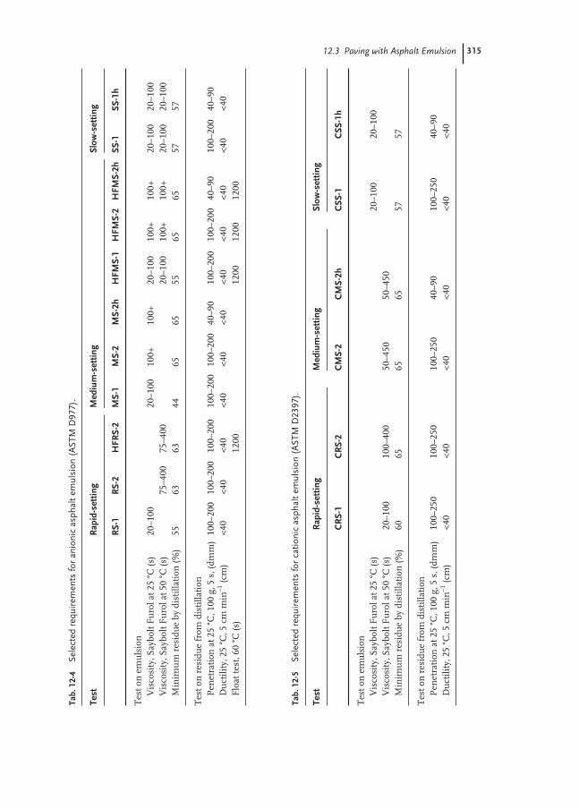
12.3 Paving with Asphalt Emulsion 315
Tab.
12-4
Sele
cted
req
uire
men
ts fo
r an
ioni
c as
phal
t em
ulsi
on (
AST
M D
977)
.
Test
Rap
id-s
ettin
gM
ediu
m-s
ettin
gSl
ow-s
ettin
g
RS-
1R
S-2
HFR
S-2
MS-
1M
S-2
MS-
2hH
FMS-
1H
FMS-
2H
FMS-
2hSS
-1SS
-1h
Tes
t on
em
uls
ion
Vis
cosi
ty, S
aybo
lt F
uro
l at 2
5°C
(s)
20–1
0020
–100
100+
100+
20–1
0010
0+10
0+20
–100
20–1
00V
isco
sity
, Say
bolt
Fu
rol a
t 50
°C (s
)75
–400
75–4
0020
–100
100+
100+
20–1
0020
–100
Min
imu
m r
esid
ue
by d
isti
llati
on (%
)55
6363
4465
6555
6565
5757
Tes
t on
res
idu
e fr
om d
isti
llati
onP
enet
rati
on a
t 25
°C, 1
00g,
5s,
(dm
m)
100–
200
100–
200
100–
200
100–
200
100–
200
40–9
010
0–20
010
0–20
040
–90
100–
200
40–9
0D
uct
ility
, 25
°C, 5
cmm
in–1
(cm
)<4
0<4
0<4
0<4
0<4
0<4
0<4
0<4
0<4
0<4
0<4
0F
loat
test
, 60
°C (s
)12
0012
0012
0012
00
Tab.
12-5
Sele
cted
req
uire
men
ts fo
r ca
tioni
c as
phal
t em
ulsi
on (
AST
M D
2397
).
Test
Rap
id-s
ettin
gM
ediu
m-s
ettin
gSl
ow-s
ettin
g
CR
S-1
CR
S-2
CM
S-2
CM
S-2h
CSS
-1C
SS-1
h
Tes
t on
em
uls
ion
Vis
cosi
ty, S
aybo
lt F
uro
l at 2
5°C
(s)
20–1
0020
–100
Vis
cosi
ty, S
aybo
lt F
uro
l at 5
0°C
(s)
20–1
0010
0–40
050
–450
50–4
50M
inim
um
res
idu
e by
dis
tilla
tion
(%)
6065
6565
5757
Tes
t on
res
idu
e fr
om d
isti
llati
onP
enet
rati
on a
t 25
°C, 1
00g,
5s,
(dm
m)
100–
250
100–
250
100–
250
40–9
010
0–25
040
–90
Du
ctili
ty, 2
5°C
, 5cm
min
–1(c
m)
<40
<40
<40
<40
<40
<40

316 12 Applications for Asphalt Modification
Chip seal: This treatment involves spraying asphalt material (heated asphalt or as-phalt emulsion) followed immediately by a thin (one stone thick) aggregate cover asschematically shown in Fig. 12-10. The aggregate is immediately rolled with a pneu-matic roller and a light brooming may be necessary to remove any excess aggregate.Cutback asphalts have been used in the past for this purpose but asphalt emulsion isnow preferred due to environmental and safety (fire hazard) concerns associatedwith cutback asphalt. A rapid setting RS, HFRS or CRS is usually used, though amedium setting MS, HFMS or CMS asphalt emulsion could be used (ASTM D977and D2397 for anionic and cationic emulsions, respectively). The cationic asphaltemulsion often provides better asphalt adhesion to the aggregate. The polymer mod-ified asphalt emulsion (2–4 % polymer by weight of asphalt) improves chip retentionand enhances pavement durability (Sect. 12.3.5).
Slurry seal: A slurry seal is a homogeneous mixture of well-graded fine aggregate,asphalt emulsion, water and mineral fillers applied to a pavement as a surface treat-ment. Slurry seal is usually applied in a thickness of 3 to 6 mm. A small amount ofmineral filler, hydrated lime, limestone dust, Portland cement or fly ash, aids in set-ting the slurry. The Slurry comes directly from a traveling mixing plant into an at-tached spreader box that spreads the slurry by a squeegee-type action as shown inFig. 12-11. The machine used for production of slurry seal is a self-contained, con-tinuous-flow mixing unit. The asphalt emulsion used in the slurry mix may be SS-1,SS-1h, CSS-1 or CSS-1h. Quick-setting (QS) asphalt emulsion is used when earlyopening to traffic is necessary.
Microsurfacing: A new slurry technique, microsurfacing, takes advantages of poly-mer modified asphalt emulsions. It can be applied at greater thicknesses than con-ventional slurry seals, allowing its use for rut-filling and is maintains a friction re-sistant surface throughout the service life. The microsurfacing mix has to set quicklyenough to accept traffic within 1 h after placement [20]. Polymer modified CSS-1hasphalt emulsion (ASTM D2397 and AASHTO M208) is used with a minimum poly-mer level of 3 %. The International Slurry Seal Association has established recom-mended performance guidelines A105 and A143 for the slurry seal and microsurfac-ing, respectively. A careful mix design (ISSA TB-139, TB-09, TB-114, TB-100, TB-147A, TB-144 and TB-113) confirming compatibility of the aggregate, polymer mod-ified asphalt emulsion, mineral filler, and other additives is essential for successfulslurry seal and microsurfacing operations.
Fig. 12-10 Schematic diagramillustrating chip seal paving.
Aggregate Particle Emulsion Residue

12.3 Paving with Asphalt Emulsion 317
12.3.2
Asphalt Emulsion Tests
Standard tests and procedures for testing asphalt emulsions are specified in ASTMD244 and AASHTO T59. These include particle charge, viscosity, storage stability,demulsibility and others. A distillation or evaporation test is used to recover the as-phalt (emulsion residue) from the emulsion. In these tests, the asphalt emulsion issubjected to a maximum of as high as 260 °C for the distillation method or 167 °C forthe evaporation. The most common tests run on the recovered residue include pene-tration, softening point, ductility, elastic recovery and torsion recovery. These testsare meant to be used as a quality control tool, (e.g. to confirm a designed polymer lev-el in the modified asphalt), but are not designed to correlate the binder performancefor each application [21]. During the residue recovery process, excess heat applied tothe polymer modified asphalt emulsion causes formation of macroscopic polymerglobules that are as large as a few mm in diameter. A minor difference in the tem-perature and length of the distillation would cause variation in the polymer mor-phology, which explains the poor reproducibility reported by the AEMA MaterialsCommittee Round Robin Studies on emulsion residue characterization [22].
12.3.3
Polymer Honeycomb Structure in Cured Asphalt Emulsion
Modified asphalt emulsion with latex is not just an emulsion of polymer-modifiedasphalt, but rather an emulsion containing dispersed latex particles in the aqueous
Fig. 12-11 Schematic diagram of a typical microsurfacing paver. Courtesy Akzo Nobel Asphalt Applications Inc.
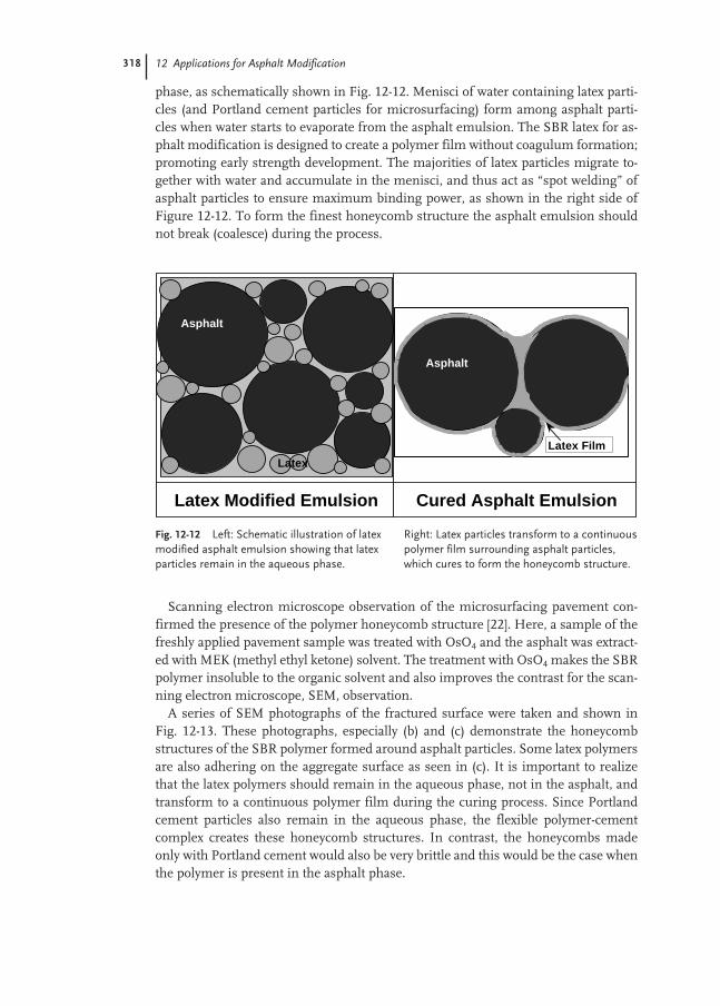
318 12 Applications for Asphalt Modification
phase, as schematically shown in Fig. 12-12. Menisci of water containing latex parti-cles (and Portland cement particles for microsurfacing) form among asphalt parti-cles when water starts to evaporate from the asphalt emulsion. The SBR latex for as-phalt modification is designed to create a polymer film without coagulum formation;promoting early strength development. The majorities of latex particles migrate to-gether with water and accumulate in the menisci, and thus act as “spot welding” ofasphalt particles to ensure maximum binding power, as shown in the right side ofFigure 12-12. To form the finest honeycomb structure the asphalt emulsion shouldnot break (coalesce) during the process.
Scanning electron microscope observation of the microsurfacing pavement con-firmed the presence of the polymer honeycomb structure [22]. Here, a sample of thefreshly applied pavement sample was treated with OsO4 and the asphalt was extract-ed with MEK (methyl ethyl ketone) solvent. The treatment with OsO4 makes the SBRpolymer insoluble to the organic solvent and also improves the contrast for the scan-ning electron microscope, SEM, observation.
A series of SEM photographs of the fractured surface were taken and shown inFig. 12-13. These photographs, especially (b) and (c) demonstrate the honeycombstructures of the SBR polymer formed around asphalt particles. Some latex polymersare also adhering on the aggregate surface as seen in (c). It is important to realizethat the latex polymers should remain in the aqueous phase, not in the asphalt, andtransform to a continuous polymer film during the curing process. Since Portlandcement particles also remain in the aqueous phase, the flexible polymer-cementcomplex creates these honeycomb structures. In contrast, the honeycombs madeonly with Portland cement would also be very brittle and this would be the case whenthe polymer is present in the asphalt phase.
Fig. 12-12 Left: Schematic illustration of latexmodified asphalt emulsion showing that latexparticles remain in the aqueous phase.
Right: Latex particles transform to a continuouspolymer film surrounding asphalt particles,which cures to form the honeycomb structure.
Asphalt
Latex Film
Asphalt
Latex
Latex Modified Emulsion Cured Asphalt Emulsion

12.3 Paving with Asphalt Emulsion 319
Do these honeycombs strong enough to maintain their structure under repeatedpoundings by heavy weight truck tires running at above 100 km h–1 throughout thelifetime of the pavement? Pavement samples were taken from Texas State Highway84 near Waco. This highway was treated with the microsurfacing in 1998. Sampleswere taken from the wheel path as well as the shoulder of the pavement. As seen inFig. 12-14, the honeycomb structure with the SBR latex polymer-cement complex isflexible enough to withstand repeated stresses after three years service at the high-way condition. Advantages of this flexible honeycomb structure with SBR latex willbe discussed later in the emulsion residue characterization.
An optical microscope observation simulating chip seal was also conducted usingSBR latex modified CRS-2 emulsion [23]. When the emulsion is placed on sand par-ticles, which are placed on the microscope slide glass, spontaneous formation of thepolymer network was observed as shown in Fig. 12-15.
12.3.4
Asphalt Emulsion Residue Characterization
The need for an appropriate residue recovery procedure for asphalt emulsion hasbeen recognized in both Europe and the US. The forced airflow drying method,which dries the emulsion at ambient temperature, provides a sufficient amount ofresidue samples within 3–5 h for the Superpave binder characterization [22]. Anexample of estimating the rutting resistance temperature, Tr (temperature atG*/sin(δ ) = 1 kPa) of microsurfacing emulsion residue is shown in Fig. 12-16. A typ-
Fig. 12-13 A series of scanning electron micro-scope photographs of the cured microsurfacingspecimen demonstrating (a) and (b) SBR poly-
mer honeycomb formed around asphalt parti-cles. (c) Some polymers also adhere on theaggregate surface.
(a)
(a) (b)
(b)
(c)
(c)
1µm
25µµm
10µµm
5µµm

320 12 Applications for Asphalt Modification
ical microsurfacing formulation consists of 100 g aggregates, 12 g of 65 % asphaltemulsion containing 3 % latex polymer, 10 g water and 1 g Portland cement. The for-mulation used for this study is the same but without the aggregate and 10 g water.
As seen in Fig. 12-16, the unmodified asphalt emulsion was made with a PG64 as-phalt and the rutting resistance temperature increased slightly from 66 °C to 68 °Cafter one month. The sample with Portland cement shows a gradual increase in Tr to71 °C within three weeks. This increase in Tr is mostly due to stiffening of the as-phalt as the phase angle of the residue increases from 82° to 88° at Tr. The value of Tr
showed a rapid increase to 76 °C within the first 3 days of curing when 3 % of the
Fig. 12-15 Photo-micrograph demon-strating spontaneousformation of polymernetwork upon curingof the CRS-2 asphaltemulsion modifiedwith 3 % cationic SBRlatex.
50µm
Latex PolymerNetwork
Fig. 12-14 SEM photographs of microsurfacing pavement taken under the wheel path; Texas State Highway 84 near Waco, paved in 1998, andsamples taken in 2001.
5µm

12.3 Paving with Asphalt Emulsion 321
SBR latex is also present in the mix. Two PG grades improvement in the rutting re-sistance was achieved after two weeks of curing. The phase angle at Tr remainednearly constant at 77–78° throughout the curing, confirming that SBR modified as-phalt binder maintains the elasticity. Differences in the phase angle of these threesamples are also summarized in Fig. 12-16.
To evaluate potential benefits on performance during its lifetime, an acceleratedcuring test was also designed. Here, the emulsion was dried one day under theforced airflow, and transferred into an oven at 60 °C, and so simulating pavementtemperature during the daytime.
Two different latex polymer levels of 3 and 5 % were studied. Three PG grades im-provement (from PG64 of the unmodified asphalt) with 3 % latex polymer takes only10 days of curing, as seen in Fig. 12-17, demonstrating the rut filling capability of themicrosurfacing system.
The European Standard for emulsions of pure and polymer modified bitumen in-cluding a residue recovery procedure and characterization of the recovered residue iscurrently under preparation.
12.3.5
Application Tests for Chip Seal and Microsurfacing
Microsurfacing: Jones et al. [24, 25] analyzed the performance of seven polymer-mod-ified asphalt emulsions for microsurfacing application. The objective of their studieswas to examine effects of different polymers on microsurfacing performance. Thesame asphalt, surfactant and aggregates were used to eliminate all other variables
Fig. 12-16 The rutting resistance temperature,Tr, of microsurfacing emulsion, emulsion pluscement and emulsion, cement and 3 % SBRlatex. Two PG grade improvement can be
observed with the polymer-cement system,which maintains elasticity of the residue asseen with the low measured phase angle.
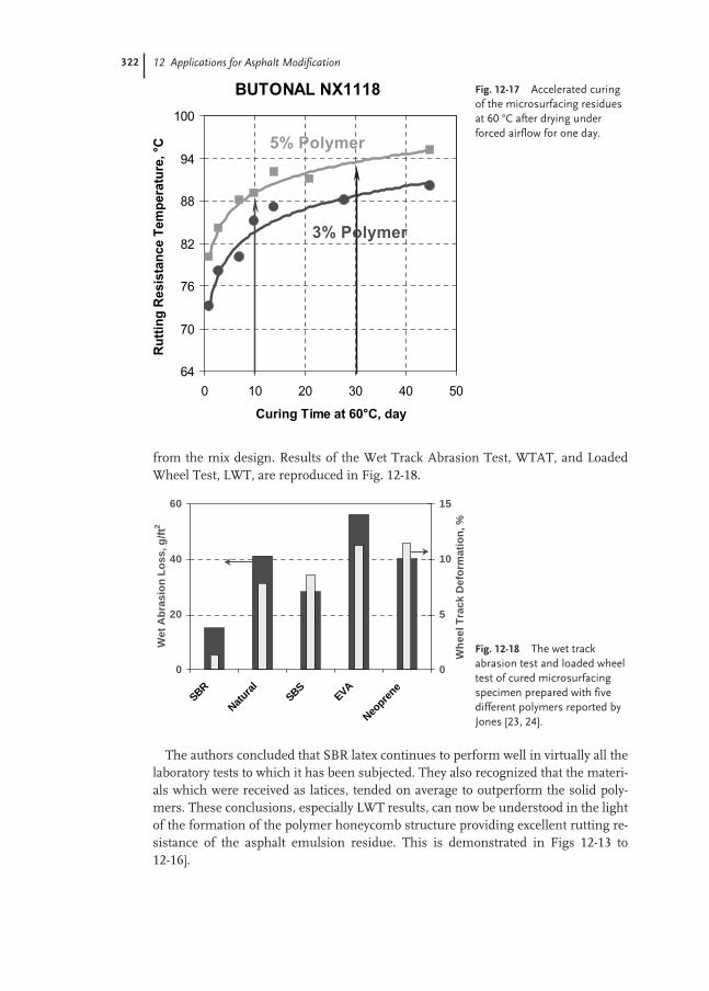
322 12 Applications for Asphalt Modification
from the mix design. Results of the Wet Track Abrasion Test, WTAT, and LoadedWheel Test, LWT, are reproduced in Fig. 12-18.
The authors concluded that SBR latex continues to perform well in virtually all thelaboratory tests to which it has been subjected. They also recognized that the materi-als which were received as latices, tended on average to outperform the solid poly-mers. These conclusions, especially LWT results, can now be understood in the lightof the formation of the polymer honeycomb structure providing excellent rutting re-sistance of the asphalt emulsion residue. This is demonstrated in Figs 12-13 to 12-16].
Fig. 12-17 Accelerated curingof the microsurfacing residuesat 60 °C after drying underforced airflow for one day.
Fig. 12-18 The wet trackabrasion test and loaded wheeltest of cured microsurfacingspecimen prepared with fivedifferent polymers reported byJones [23, 24].
0
20
40
60
SBR
Natura
lSBS
EVA
Neopre
ne
We
t A
bra
sio
n L
os
s, g
/ft2
0
5
10
15
Wh
ee
l Tra
ck D
efo
rmat
ion
, %

12.4 Eco-efficiency Analysis 323
Chip seal: Loose chips from a freshly paved road are the major safety concern forchip seal operation, and several attempts were reported in the literature to develop alaboratory procedure to simulate the field experience. A modified fretting test (alsoknow as the abrasion cohesion test Esso, ACTE) appears to be the most success-ful [26, 27]. In this test, a known amount of CRS-2 asphalt emulsion and aggregatesare spread on a roofing felt, and then rolled with a 30 kg rubber roller. The sample issubjected to the shearing action of a horizontal steam-hose, which is attached to aHobart sun and planet mixer, and the percentage of retained chips is recorded as afunction of curing time.
An example of the test results is shown in Fig. 12-19, which demonstrates early co-hesion development with the latex modified asphalt emulsion [28]. Marchal et al. [27]report that the maximum chip retention does not exceed 80 % even with a fully curedasphalt emulsion, and approximately 50 % chip retention is considered to be strongenough to be open to traffic. Use of a specially designed brush appears to reduce aproblem of chip build-up around the steam-hose [29].
12.4
Eco-efficiency Analysis
Recent study by Queiroz et al. [30] demonstrated a statistically significant relation-ship between a country’s economical development and its road infrastructure(Fig. 12-20). A well-developed and well-maintained highway system is credited forimprovements in access to goods and services, education and employment opportu-nities. A person living in Australia has, on average, access to 27-lane meters of pavedroad. In comparison, it is only 16-lane centimeters for people in China! Improve-ment in cold mix technology to provide durable pavements would result in signifi-cant impact on the well being of people living in these developing countries. A coldmix plant, using asphalt emulsion, requires less initial capital investment and lowerenergy consumption than a hot mix plant.
For developed countries, environmental focus has shifted from pollution preven-tion to sustainable development. BASF developed a so-called eco-efficiency analysis,as an internal decision making tool, to help in evaluating products and processes for
Fig. 12-19 Results of modifiedfretting test demonstratingadvantages of the early chipretention with cationic SBRlatex modified emulsion.
0
20
40
60
80
0 30 60 90 120
Curing time, min.
Ch
ip r
eten
tio
n, %
Latex Modified
Unmodified
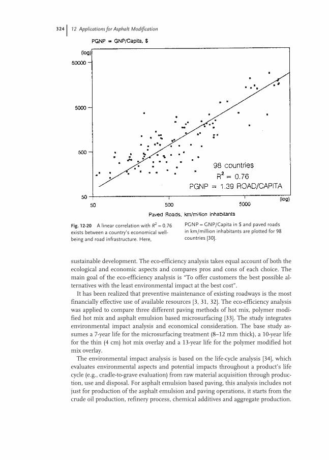
324 12 Applications for Asphalt Modification
sustainable development. The eco-efficiency analysis takes equal account of both theecological and economic aspects and compares pros and cons of each choice. Themain goal of the eco-efficiency analysis is “To offer customers the best possible al-ternatives with the least environmental impact at the best cost”.
It has been realized that preventive maintenance of existing roadways is the mostfinancially effective use of available resources [3, 31, 32]. The eco-efficiency analysiswas applied to compare three different paving methods of hot mix, polymer modi-fied hot mix and asphalt emulsion based microsurfacing [33]. The study integratesenvironmental impact analysis and economical consideration. The base study as-sumes a 7-year life for the microsurfacing treatment (8–12 mm thick), a 10-year lifefor the thin (4 cm) hot mix overlay and a 13-year life for the polymer modified hotmix overlay.
The environmental impact analysis is based on the life-cycle analysis [34], whichevaluates environmental aspects and potential impacts throughout a product’s lifecycle (e.g., cradle-to-grave evaluation) from raw material acquisition through produc-tion, use and disposal. For asphalt emulsion based paving, this analysis includes notjust for production of the asphalt emulsion and paving operations, it starts from thecrude oil production, refinery process, chemical additives and aggregate production.
Fig. 12-20 A linear correlation with R2 = 0.76exists between a country’s economical well-being and road infrastructure. Here,
PGNP = GNP/Capita in $ and paved roadsin km/million inhabitants are plotted for 98countries [30].

12.5 Concluding Remarks 325
It also includes waste production, recycling operation, and transportation and distri-bution of all these activities.
These environmental impacts are classified into five parameters: raw materialsconsumption, energy consumption, emission, potential health effects, and risk ofaccident and misuse. When all factors were considered, microsurfacing had a lowerenvironmental “footprint” as shown in Fig. 12-21. The thicker hot mix layer let to agreater use of natural resources, as well as higher energy consumption and emissioninvolved in its manufacture and transportation.
These environmental impacts were weighed according to how surveys said thepublic viewed their relative importance. When this result is combined with the an-nual costs of the treatments, the overall conclusion is that microsurfacing provides abetter balance between cost-effectiveness and environmental impact than does a thinhot mix overlay as shown with the eco-efficiency portfolio of the preventive mainte-nance in Fig. 12-22. Here, all costs and environmental impacts were averaged over
Fig. 12-21 Environmental profiles for microsur-facing and thin hot mix overlays. Microsurfacinghas a lower environmental “footprint” than twoother alternative treatments.
0,00
0,50
1,00Energy
Emissions
Potential health effects
Risk potential
Raw material
Cold-mix microsurfacing
Hot-mix asphalt
Modified hot-mix asphalt
Fig. 12-22 Eco-efficiency port-folio combines environmentalimpact with costs of treat-ments. Results demonstratethat microsurfacing is more“Eco-Efficient” than hot mixoverlays.
Cold-mix micro-
surfacing
Hot-mix asphalt
Modified hot-mix asphalt
0,2
1,0
1,80,21,01,8
Costs (relative)
Env
ironm
enta
l im
pact
High eco-efficiency
Low eco-efficiency
326 12 Applications for Asphalt Modification
each year of the life of the treatment. The study also suggests that future improve-ment in microsurfacing techniques could lead to additional cost and environmentaladvantages [33].
12.5
Concluding Remarks
Asphalt roads account nearly 95 % (3 300 000 km) of the paved roads in the US Ad-dition of as little as 2–3 % of polymers in the asphalt improves rutting resistance, andprevents premature fatigue and cold fracture crack formation. The latex can be usedfor both hot mix and emulsion based paving. Recent studies [33] on eco-efficiencyanalysis clearly demonstrate economical and ecological advantages of the asphaltemulsion based microsurfacing for preventive maintenance.
Latex, because it is an aqueous dispersion, is the ideal polymer for modification ofan asphalt emulsion. Commercial availability of the cationic form makes SBR latexideal for chip seal, slurry seal and microsurfacing applications, which are predomi-nantly used for preventive maintenance.
Acknowledgement
The author is grateful to Glynn Holleran of Valley Slurry Seal Co., Drs Alan Jamesand Julia Wates of Akzo Nobel Surface Chemistry LLC, Dr. Per Redelius of ABNYNÄS Petroleum, Jeremy Kissock of BASF New Zealand and Mike Taylor of BASFCorporation for their valuable comments and advice.
References
1 The Asphalt Institute, The Asphalt Handbook, Manual Series No. 4 (MS-4).
2 Symposium of World Road Bitumen Emulsion Producers, Bordeaux, Septem-ber 1997.
3 F. L. Roberts, P. S. Kandhal, E. R.Brown, D. Y. Lee, T. W. Kennedy, HotMix Asphalt Materials, Mixture Designand Construction, NAPA Research andEducation Foundation Textbook, 2ndEdition, 1996.
4 G. King, H. King, R. D. Pavlovich, A. L.Epps, P. Kandhal, Additives in Asphalt,J. Assoc. Asphalt Paving Technol. 75thHistorical Review and Index of Journals,1975–1999, 1999, 68A, 32–69,.
5 T. Hancock, UK Patent No. 9952, November 21, 1843.
6 S. Shuler, J. A. Epps, Presented to theRubber Division, American ChemicalSociety, Philadelphia, PA, 1982.
7 D. C. Thompson, J. F. Hagman, Assoc.Asphalt Paving Technol. 1958, 55.
8 Construction of Hot Mix Asphalt Pave-ments, Manual Series No. 22, 2nd edn,Asphalt Institute, Lexington, KY.
9 Use of Modified Bituminous Binders,Special Bitumens and Bitumens with Ad-ditives in Pavement Applications, WorldRoad Association (PIARC) TechnicalCommittee Flexible Roads (C8), Labo-ratoire central des Ponts et Chaussées,September 1999.
10 World Road Association,www.piarc.icpc.fr

References 327
11 Superpave Binder Manual, Superpave Series No. 1 (SP-1), Asphalt Institute,Lexington, KY.
12 D. A. Anderson, D.W. Christensen, H. U. Bahia, M.G. Sharma, C.E. Antle, J. Button, Binder Characterization andEvaluation Volume 3: Physical Characteri-zation, Strategic Highway Research Pro-gram (SHRP-A-369), National ResearchCouncil, Washington, DC 1994.
13 W. Arand, O. Harder, B. Herr, AsphaltContaining Conventional and Polymer-Modified Bitumens in High and Low Temperature Conditions, PIARC XIXthWorld Road Congress, Marrakesh, Sept. 1991.
14 H. Bahia, W. Hislop, H. Zhai, A. Grangel, Classification of AsphaltBinders into Single and Complex Binders,Association of Asphalt Paving Technolo-gist, 67, 1998.
15 L. H. Lewandowski, Polymer Modifica-tion of Paving Asphalt Binders, RubberChemistry Technol. 1994, 67, 447–480.
16 B. Brûlé, Y. Brion, A. Tanguy, Paving As-phalt Polymer Blends: Relationships Be-tween Composition, Structure and Prop-erties, J. Asphalt Paving Technol. 1988,57, 41–64.
17 V. Wegan, B. Brûlé, The Structure of Polymer Modified Binders and Corresponding Asphalt Mixtures, J. Assoc. Asphalt Paving Technol. 1999, 68,64–88.
18 AEMA Recommended Performance Guide-lines, 2nd edn, Asphalt Emulsion Manu-factures Association, Annapolis, Mary-land.
19 A Basic Asphalt Emulsion Manual, Asphalt Institute Manual Series No. 19, 2nd edn, Lexington, KY.
20 R. Hassan, State-of-the-practice Design,Construction and Performance of Micro-surfacing, FHWA-SA-94-051, FederalHighway Administration, Washington,DC, 1994.
21 L. D. Coyne, Evaluation of Polymer Mod-ified Chip Seal Coats, J. Asphalt PavingTechnol. 1988, 57, 545–575.
22 K. Takamura, Comparison of EmulsionResidues Recovered by the Forced Air-
flow and RTFO Drying, AEMA/ISSAProc. 2000, 1–17.
23 K. Takamura, W. Heckmann, PolymerNetwork Formation in the EmulsionResidue Recovered by Forced Air Dry-ing, Proc. Int. Symp. Asphalt EmulsionTechnology, 1999, pp. 185–194.
24 D. R. Jones, AEMA Annual Meeting,Nov. 1988.
25 D. R. Jones, A. C. Ng, ISSA AnnualMeeting, Feb. 1989.
26 E. Cornet, Esso Abrasion CohesionTest, A Description of the CohesiveBreaking of Emulsions for Chip Seals,Proc. Int. Symp. Asphalt Emulsion Tech-nology, 1999, pp. 346–355.
27 J. L. Marchal, P. Julien, N. Boussad, Bitumen Emulsion Testing: Towards a Better Understanding of Emulsion Behavior, ASTM Symp. Asphalt Emul-sion, 1990.
28 J. Wates, A. James, Akzo Nobel inter-nal results.
29 L. Barnat, Predictive Capabilities forMaintenance Products, AEMA/ISSAProc. 2000, 19–49.
30 C. Queiroz, R. Haas, Y. Cai, NationalEconomic Development and ProsperityRelated to Paved Road Infrastructure,Transportation Res. Record 1455, 1994.
31 M. S. Mamlouk, J. P. Zaniewski, Pave-ment Preventive Maintenance: De-scription, Effectiveness, and Treat-ments, Symp. Flexible Pavement Reha-bilitation and Maintenance, ASTM STP1349, 1999, pp. 121–135.
32 I. M. Syed, T. J. Freeman, R. E. Smitn,Effectiveness of Highway MaintenanceTreatments Used in Texas, Symp. Flexible Pavement Rehabilitation andMaintenance, ASTM STP 1349, 1999,pp. 136–150.
33 K. Takamura, K.P. Lok, R. Wittlinger,AEMA/ARRA Annual Meeting, Febru-ary, 2001.
34 A. Horvath, C. Hendrickson, Compari-son of Environmental Implications ofAsphalt and Steel-Reinforced ConcretePavements, Transportation Res. Record1626, 1998, 105–113.


329
13
Applications of Redispersible Powders
Hermann Lutz and Christoph Hahner
13.1
Introduction
The building/construction industry is the main industry for redispersible powders.Over the years the usage of dry mortar technology has been developed dramaticallyand modernized the way mortars are being used on a job-site. The invention of re-dispersible powders enabled the industry for the first time to produce pre-packed,polymer modified building materials that needed only the addition of water beforeapplication. These materials, known as dry mortar mixes guarantee defined and con-sistent performance of construction materials.
In the past up until to the 1950s mortars were exclusively used and applied as job-site mixed mortars, where the mineral binder (mostly cement) and the aggregates(mostly silica sand) were transported separately to the job-site. The aggregates andthe mineral binders were then mixed together by hand in the appropriate ratio andwere gauged with water in order to obtain the fresh mortar ready to apply.
During the 1950s and 1960s both in Western Europe and the US, but especially inGermany, there was a fast growing demand in the construction industry for newbuilding materials and technologies. Several reasons, like shortage of skilled work-men, the need of shorter construction time together with cost reduction, increasinglabor costs, the diversification of building materials suitable for specific applications,the request for new materials and an increased demand for better quality of con-structions were supporting a movement towards dry mix mortar technology.
The job-site mix mortar technology is not able to meet adequately all these re-quirements. As a practical consequence, the development of the modern construc-tion and building chemical industry in the countries of the West from the 1960s on-wards was influenced mainly by two important trends, which can be seen nowadaysin the whole world. First there was a replacement of the job-site mixed mortars bypremixed and pre-packed dry mix mortars, which are more and more applied withmachines. Secondly mortars started to be modified with polymer binders in order toimprove the product quality and to meet the requirements of the modern buildingindustry. As a consequence the two-pack systems (mortar + dispersion) as well as

330 13 Applications of Redispersible Powders
ready to use products (liquid or paste) were substituted by one-pack systems, whichare modified with redispersible powders, pre-mixed and pre-packed dry mix mortars.
13.2
Manufacturing of Redispersible Powders
A redispersible powder is by definition a polymer in a powdered form that can beredispersed by adding water to it. The resulting emulsion will fulfill the functionali-ty of a polymeric dispersion binder, normally within a cementitious or gypsum basedsystem. Redispersible powders are manufactured by spray drying an emulsion (Fig. 13-1).
Over 90 % of all industrial manufactured polymer dispersions are produced byemulsion polymerization. The most important monomers, which are being used forapplications in the building/construction industry, are vinyl acetate, ethylene, versa-tic acid esters, vinyl chloride, styrene and acrylics. Especially the use of ethylene as aco-monomer offers some extraordinary advantages:– environmentally safe,– no saponification,– UV-resistant (no yellowing),– very hydrophobic,– ideal for co-polymerization with vinyl acetate,– very low glass transition temperature, Tg, of –93 °C,– very flexible, and– good adhesion to most of the substrates.
To guarantee the performance of a redispersible powder in its final application aprotective colloid is added to the emulsion before the spraying process. The colloidprotects the polymer particles from film forming during the spray drying process
Fig. 13-1 Spray-driedpolymer particle.

13.2 Manufacturing of Redispersible Powders 331
and is also responsible for that the powder will redisperse in water again (Figs 13-2and 13-3).
Fig. 13-2 Dispersion/redispersion – comparison of particle size distribution.
Fig. 13-3 The spray-dry process.
dispersion protective�colloid
redispersible�powder
redispersion
spray�drying
adding�water
drying
dispersion
redispersion
particle concentration particle concentration
particle concentration particle concentration
particle size (diameter)
particle size (diameter)
0 2 4 6
69ppm
69ppm
92ppm
92ppm
0 2 4 6
wei
ght
dis
trib
utio
n cu
rve
wei
ght
dis
trib
utio
n cu
rve
1 1 10
1 1 10
100%
80
60
40
20
0
100%
80
60
40
20
0

332 13 Applications of Redispersible Powders
Over the years poly vinyl alcohol (abbreviated PVOH or PVAl) proofed to be themost preferred protective colloid for that purpose. In a cementitious environmentPVOH will be partly saponified and also absorbed of fine particles within a mortar,i.e. cement and fillers. This results in a film forming of the dispersed polymer and fi-nally the polymer film is not redispersible any more. Since the polymer film (actingas a binder) is distributed throughout the cement matrix it improves dramatically theadhesion, abrasion resistance, flexural strength, flexibility, water impermeability/wa-ter repellency (hydrophobicity) and workability of a cementitious system.
13.3
Dry Mortar Technology
The invention of redispersible powders by Wacker-Chemie in 1953 made for the firsttime the production of polymer modified dry mix mortars possible, which are nowa-days referred to as one pack or one component system (“bagged” materials). Newconstruction methods and building materials, which had the need for more safety,reliability, durability, efficiency and economy, have been achieved by using modernmethods like the dry mix mortar technology. As a consequence worldwide the “job-site mix technology” and the modification of mortars with liquid polymers on job-sites were and are substituted by polymer modified dry mix mortars. The productcharacteristics are very well adapted to the requirements of modern constructiontechnologies, materials and climates.
Pre-mixed and pre-packed dry mix mortars not only increase significantly the pro-duction performance and the productivity on construction sites, but guarantee alsothat high and constant quality binder, aggregates, and additives are being mixed ex-actly in the same ratio, thus ensuring a consistent high quality level within dry mixmortars. Furthermore, dry mix mortars offer solutions to specific problems that areprecisely tailored to certain types of construction/material specifications. Especiallyin the USA, the legal aspect of a reliable, properly conducted construction job is veryimportant to each manufacturer of construction materials.
The use of redispersible powders and therefore also the use of polymer modifiedpowdered mortars is already for many decades standard in the construction industryin Europe and North America (predominantly in the USA). Other marketplaces allover the world like South America, Asia, Africa and Australia are in the process fol-lowing that example. More and more environmental reasons ask also for the usage ofdry mortars, since the recycling of buckets becomes more and more an issue. Drymortars are also easy to store, transport and do not require biocides.
Typically dry mortar mixes contain the components listed in Tab. 13-1 and aredefined according to German standard DIN 18557.
The application areas of dry mix mortars are:– ceramic tile adhesive,– tile grouts,– E.I.F.S. (exterior insulation and finish systems)/E.T.I.C.S. (exterior thermal insu-
lation compounds),

13.4 Markets and Application Areas of Redispersible Powders 333
– self-leveling over- and underlayments, screeds,– stucco, skim coat,– topcoat/finish coat,– patch and repair mortar,– adhesive mortars (for all kind of substrates),– crack isolation membrane,– powder paints,– gypsum based compounds (joint fillers),– waterproof membranes/sealant slurry,– pool decking, and– stamped concrete.
The following paragraphs will describe the most important and most developedapplication areas for redispersible powders as they are ceramic tile adhesives/ tilegrouts, thermal insulation systems (E.I.F.S.), self-leveling underlayments, patch andrepair mortars, as well as water proof membranes (sealant slurries).
13.4
Markets and Application Areas of Redispersible Powders
To meet today’s technical requirements, almost all dry mix mortars require polymermodification. Many cementitious mortars contain cellulose ethers as an additive toimprove water retention and workability. However, after setting and drying they willadhere poorly or not at all to most of the substrates used in modern constructiontechnology such as polystyrene panels, fiber panels, wood panels, closed and non-ab-sorbent substrates or old tiles. In addition, cementitious mortars are very hard, brit-tle and inflexible materials, whereas for many applications flexible and deformablecementitious materials are essential. As a consequence for almost all applications inmodern construction, the modification of cementitious mortars with polymers is amust. In dry mix mortars the mineral binder, cement, and the polymer binder, re-dispersible powder, are ideal partners. The combination of both in a dry mix mortar
Tab. 13-1 Dry mortar mixes.
Mineral binders Aggregates fillers Polymer binder Additives
Portland cement (OPC) Silica sand Redispersible powder Cellulose etherHigh Alumina Cement (HAC) Hydrated lime PigmentSpecial cement Dolomite sand DefoamerHydrated lime Marble sand Air-entraining agentGypsum, Lightweight fillers Retarderanhydrite Special and functional fillers Accelerator
ThickenerHydrophobing agentsPlasticizers
334 13 Applications of Redispersible Powders
provides outstanding synergistic properties and characteristics, which cannot beachieved by either of the binders alone.
13.4.1
Adhesives for Ceramic Tiles
Ceramic tiles as well as natural stone were previously installed exclusively by usingthe thick bed mortar technique. Silica sand and cement were mixed together on thejob-site, in order to produce a simple cement mortar with a cement/sand ratio of ap-proximately 1:4 to 1:5. In some countries only cement is still used in order to settiles. After having applied (“buttered”) the mortar at a thickness of 15 to 30 mm (0.6to 1.2 inch) on the reverse side of the water-soaked or pre-wet tile, the tile is pressedinto the pre-wet surface. The tiles have to be tapped to ensure uniformity and flat-ness of the tile surface, thus obtaining a final mortar bed of 10 to 25 mm (0.4 to 0.8inch). This procedure causes not only compaction of the mortar, but leads in addi-tion to the migration of the fine cement particles into the porous back side of the tilesand the porous substrate as well. This process assures the mechanical fixing of thetile in the mortar bed. This type of mortar has no slip resistance. Therefore tiling ofa vertical substrate has to be started at the bottom and distance splinters becomenecessary. The described procedure shows very clearly that the thick bed method is avery time, cost and material consuming process. More significantly, there are tech-nical restrictions using this technique. One of the examples is that only small,porous tiles can be applied over porous, solid and strong mineral surfaces. The ap-plication of tiles over wood would be almost impossible, since a mortar without anypolymer modification would not only be not flexible enough to withstand the move-ment of a wood substrate over an extended period of time, it would also have no suf-ficient adhesion to the substrate. Consequently severe damage could occur andtherefore the thin bed mortar technique has replaced the thick bed mortar techniquein most industrial countries.
It started in the USA in the early 1950s by adding a polymeric binder in form of aliquid latex dispersion to a job-site mixed mortar (see Chapter 8). Nowadays dry mixmortars modified with redispersible powders dominate this market segment moreand more. After gauging the polymer modified dry mix mortar with water, it can beapplied with a notched trowel, producing a ribbed mortar bed of uniform thickness.Due to the good water retention capacity of the thin bed mortar, neither the tiles northe substrate have to be pre-wet. The tiles are pressed into the thin layered mortarwith a slightly twisting movement of the tile. An anti-sag ceramic tile adhesive allowsinstalling tiles on vertical substrates without using distance splinters between thetiles. The tile installer can also start from the top of the wall instead of the bottom.The mortar bed, which fixes the tiles, has a thickness of approximately 2 to 4 mm (upto 0.25 inch). Since this method clearly uses less material, it is more cost effective,can be used more universally; its execution is clearly simpler, faster and safer. Theclear advantages of dry mix mortars modified with redispersible powders, which ap-ply also for tile grouts, are:

13.4 Markets and Application Areas of Redispersible Powders 335
– good workability, fast and easy to use, creamy consistency,– good water retention, which results in a long open time and good adjustability
even at high temperatures, and– substantial anti-sag properties, if required.
As far as the formulations for ceramic tile adhesives go there is a high variety ofmortars offered in the market place in order to meet all the specific requirements. Amajor difference, for example, between Europe and the United States is the usage ofwood as a substrate in the USA. Differences in the formulation are also determinedby requirements of specifications or application circumstances like interior or exteri-or, wall tile or floor tile, vitrified tile or more porous tile, fast setting or regularsetting, flexible or even highly flexible. The availability of certain raw materials i.e.silica sand determines very often how a formulation will perform.
The two most important specifications worldwide are the European Norms “EN”and the American Standards ANSI 118.1-1999. The biggest difference between thetwo standards is the principal test setup. The European Standards require mostlytensile bond adhesion testing where else the American Standard uses shear bondtesting. The other difference is clearly the storage conditions for the specimen beforetesting. A listing of both standards is shown in Tab. 13-2.
Cement-based standard tile adhesives can be classified in very simple (low quality)tile adhesives, which do not contain any polymeric binder. They do not meet Euro-pean or American Standards. Such tile adhesives, providing a pure mechanical fixa-tion can only be used for fixing small, very porous tiles. The substrate is supposed tobe dimensionally stable, sound and solid as well as not showing any shrinkage ormovement. If exposed to higher temperature or frost, there is a higher risk of failure.Non-modified mortars show for the most part no long-term performance.
Simple tile adhesives have already a polymer modification of 1 to 1.5 % of a redis-persible powder (calculated on total formulation). Such tile adhesives meet someparts of the mentioned national standards, but usually fulfill not all requirements.Only the usage of tiles with a medium porosity and small size could result in accept-able results with these types of adhesives.
Tab. 13-2 EN and ANSI standards for CTAs.
European standardsEN 12004 Definitions and specificationsEN 1308 Anti-sagEN 1347 Wetting capability (coverage)EN 1346 Open timeEN 1348 Tensile adhesion testing, including heat and freeze-thaw storageEN 1324 Shear-strength for masticsEN 12002 Deformability of cementitious CTA
US standardsANSI A 118.4 Specifications for Latex Portland cement mortarANSI A 118.11 Specifications for EGP (exterior glue plywood) Latex–Portland cement mortar
336 13 Applications of Redispersible Powders
Standard ceramic tile adhesives of good quality need approximately 1.5 to 3 % ofredispersible powder on total dry mix. They meet the new European Norm for tile ad-hesives (mostly only C1 level) and pass also the ANSI specification 118.4 and 118.11.Larger formatted tiles can be applied with these materials over porous or less porous,dimensionally stable substrates. They are suitable for interior as well as exterior ap-plication. For standard applications these modified mortars provide higher qualitysecurity and a certain long-term stability, very much depending on the factors likeclimate conditions, weight traffic etc.
Finally flexible (5 to 8 % of redispersible powder) and very flexible ceramic tilemortars with a polymer modification beyond 8 % up to even 25 %, guarantee the bestperformance over all, very good adhesion on all types of substrates with all types andsizes of tiles. These adhesives are used more universally and offer a much greater ap-plication variety, safety, as well as long-term durability and reliability. Nowadaysthese mortars are more and more used to fix the very popular highly vitrified tiles(water absorption <0.1 %) and natural stone tiles (like marble) in any format. Thesubstrate can be non-porous and inorganic as well as wood. Even if the substrate stillshows to a certain degree of shrinkage or expansion, including other types of move-ments or vibrations, these quality adhesives could be used to set tiles in a safe anddurable way. Typical application examples for flexible ceramic tile mortars are:– floor heat system within the substrate,– to heat exposed surfaces, like i.e. tiles on a porch exposed to sunlight,– tiles over tiles,– over gypsum boards,– over backer boards,– over wood,– on water proof membranes,– on thermal and sound insulation panels, and– on light-weight concrete blocks.
Tests conducted by international research and test institutes have proved that it isof high importance that cementitious adhesives provide a sufficient deformabilityand a certain degree of plasticity [1–4]. Only in that way, long-term durability andfunctionality can be guaranteed. Adhesive mortars have to be able to absorb stressesthat occur between two materials as tiles and substrate in order to prevent damages.Typical damages are cracking or even delaminating of the tiles. Irreversible differen-tial movement, such as shrinkage causes always stress between tile and substrate(fresh concrete is always likely to shrink). Reversible movements of the substrate likevibrations and thermal movements due to heat or cold are also sources of stress be-tween substrate, adhesive and tile. The different modulus of elasticity of tiles andsubstrate is also enhancing the stress within a ceramic tile mortar (Fig. 13-4).
European Norm EN 1348 addresses this issue in a heat test as well as in a freeze/thaw test. Shear stress between substrate and tile normally concentrates in the pe-ripheral zones of a tile. That means, the bigger the tile the higher the flexibility of theadhesive has to be in order to avoid cracking or delaminating of the tile. The flexibil-ity (deformation capability) of a ceramic tile adhesive depends on the polymer/ce-ment ratio. It is one of the two most important ratios to be determined in a ceramic

13.4 Markets and Application Areas of Redispersible Powders 337
tile mortar (the other one is the water/cement ratio). The German test DIN 18156/3,as well as EN 12002, measures the flexibility of ceramic tile adhesives. As a result ofthese tests it can clearly be shown, that the higher the polymer/cement ratio thehigher the flexibility of a mortar system (Fig. 13-5).
It is very important to mention that the deformation capability of a given cementi-tious system also depends to a large extent on the degree of hydration of the cement.Consequently, the flexibility of different adhesives can only be compared at identical
Fig. 13-4 The stress between substrate and tile.
initialdimension
initialdimension
initialdimension
initialdimension
shrinkage of substrateeg. shrinkage of concrete
expansion of tileseg. thermal expansion
tiles
deformableadhesive mortar
substrateeg. concrete
tiles
rigid, non-deformableadhesive mortar
substrateeg. concrete
substrateeg. concrete
tiles
tiles
substratreeg. concrete
Fig. 13-5 The flexibility of ceramic tile adhesives.
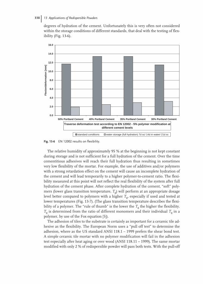
338 13 Applications of Redispersible Powders
degrees of hydration of the cement. Unfortunately this is very often not consideredwithin the storage conditions of different standards, that deal with the testing of flex-ibility (Fig. 13-6).
The relative humidity of approximately 95 % at the beginning is not kept constantduring storage and is not sufficient for a full hydration of the cement. Over the timecementitious adhesives will reach their full hydration thus resulting in sometimesvery low flexibility of the mortar. For example, the use of additives and/or polymerswith a strong retardation effect on the cement will cause an incomplete hydration ofthe cement and will lead temporarily to a higher polymer-to-cement ratio. The flexi-bility measured at this point will not reflect the real flexibility of the system after fullhydration of the cement phase. After complete hydration of the cement, “soft” poly-mers (lower glass transition temperature, Tg) will perform at an appropriate dosagelevel better compared to polymers with a higher Tg, especially if used and tested atlower temperatures (Fig. 13-7). (The glass transition temperature describes the flexi-bility of a polymer. The “rule of thumb” is the lower the Tg the higher the flexibility.Tg is determined from the ratio of different monomers and their individual Tg in apolymer, by use of the Fox equation [5]).
The adhesion of tiles to the substrate is certainly as important for a ceramic tile ad-hesive as the flexibility. The European Norm uses a “pull off test” to determine theadhesion, where as the US standard ANSI 118.1 – 1999 prefers the shear bond test.A simple ceramic tile mortar with no polymer modification will fail in the adhesiontest especially after heat aging or over wood (ANSI 118.11 – 1999). The same mortarmodified with only 2 % of redispersible powder will pass both tests. With the pull-off
Fig. 13-6 EN 12002 results on flexibility.
0.0
2.0
4.0
6.0
8.0
10.0
12.0
14.0
16.0
50% Portland Cement 40% Portland Cement 35% Portland Cement 30% Portland Cement
Traverse deformation test according to EN 12002 - 5% polymer modification at different cement levels
Fle
xio
n/d
efo
rmat
ion
[m
m]
standard conditions water storage (full hydration) 7d sc/ 14d in water/ 21d sc
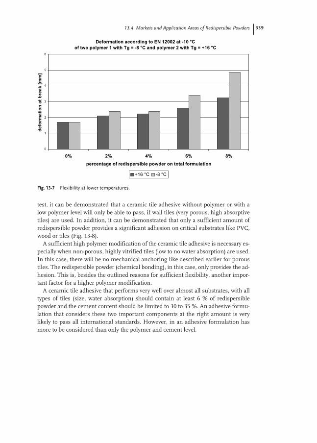
13.4 Markets and Application Areas of Redispersible Powders 339
test, it can be demonstrated that a ceramic tile adhesive without polymer or with alow polymer level will only be able to pass, if wall tiles (very porous, high absorptivetiles) are used. In addition, it can be demonstrated that only a sufficient amount ofredispersible powder provides a significant adhesion on critical substrates like PVC,wood or tiles (Fig. 13-8).
A sufficient high polymer modification of the ceramic tile adhesive is necessary es-pecially when non-porous, highly vitrified tiles (low to no water absorption) are used.In this case, there will be no mechanical anchoring like described earlier for poroustiles. The redispersible powder (chemical bonding), in this case, only provides the ad-hesion. This is, besides the outlined reasons for sufficient flexibility, another impor-tant factor for a higher polymer modification.
A ceramic tile adhesive that performs very well over almost all substrates, with alltypes of tiles (size, water absorption) should contain at least 6 % of redispersiblepowder and the cement content should be limited to 30 to 35 %. An adhesive formu-lation that considers these two important components at the right amount is verylikely to pass all international standards. However, in an adhesive formulation hasmore to be considered than only the polymer and cement level.
Fig. 13-7 Flexibility at lower temperatures.
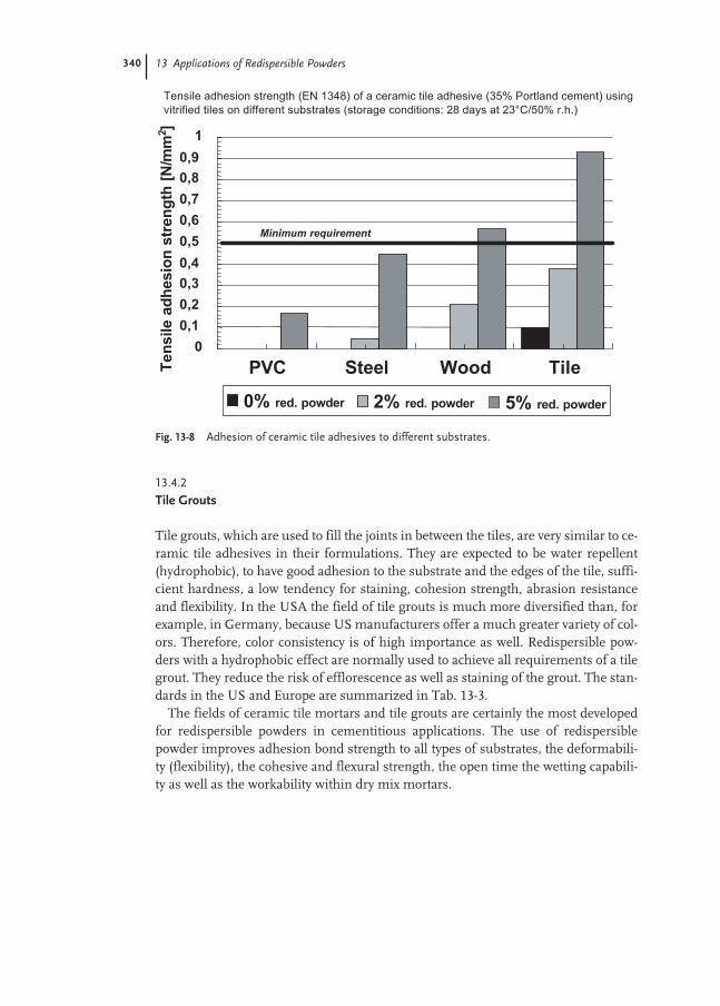
340 13 Applications of Redispersible Powders
13.4.2
Tile Grouts
Tile grouts, which are used to fill the joints in between the tiles, are very similar to ce-ramic tile adhesives in their formulations. They are expected to be water repellent(hydrophobic), to have good adhesion to the substrate and the edges of the tile, suffi-cient hardness, a low tendency for staining, cohesion strength, abrasion resistanceand flexibility. In the USA the field of tile grouts is much more diversified than, forexample, in Germany, because US manufacturers offer a much greater variety of col-ors. Therefore, color consistency is of high importance as well. Redispersible pow-ders with a hydrophobic effect are normally used to achieve all requirements of a tilegrout. They reduce the risk of efflorescence as well as staining of the grout. The stan-dards in the US and Europe are summarized in Tab. 13-3.
The fields of ceramic tile mortars and tile grouts are certainly the most developedfor redispersible powders in cementitious applications. The use of redispersiblepowder improves adhesion bond strength to all types of substrates, the deformabili-ty (flexibility), the cohesive and flexural strength, the open time the wetting capabili-ty as well as the workability within dry mix mortars.
Fig. 13-8 Adhesion of ceramic tile adhesives to different substrates.
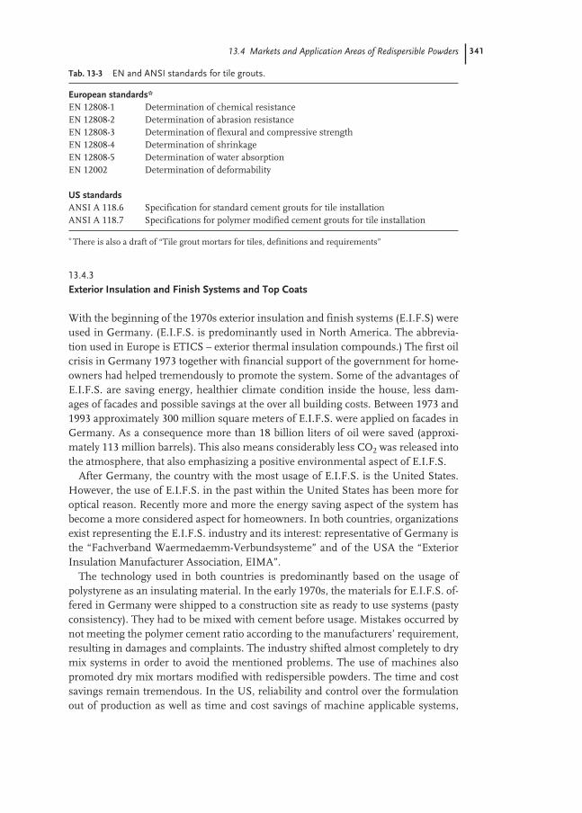
13.4 Markets and Application Areas of Redispersible Powders 341
13.4.3
Exterior Insulation and Finish Systems and Top Coats
With the beginning of the 1970s exterior insulation and finish systems (E.I.F.S) wereused in Germany. (E.I.F.S. is predominantly used in North America. The abbrevia-tion used in Europe is ETICS – exterior thermal insulation compounds.) The first oilcrisis in Germany 1973 together with financial support of the government for home-owners had helped tremendously to promote the system. Some of the advantages ofE.I.F.S. are saving energy, healthier climate condition inside the house, less dam-ages of facades and possible savings at the over all building costs. Between 1973 and1993 approximately 300 million square meters of E.I.F.S. were applied on facades inGermany. As a consequence more than 18 billion liters of oil were saved (approxi-mately 113 million barrels). This also means considerably less CO2 was released intothe atmosphere, that also emphasizing a positive environmental aspect of E.I.F.S.
After Germany, the country with the most usage of E.I.F.S. is the United States.However, the use of E.I.F.S. in the past within the United States has been more foroptical reason. Recently more and more the energy saving aspect of the system hasbecome a more considered aspect for homeowners. In both countries, organizationsexist representing the E.I.F.S. industry and its interest: representative of Germany isthe “Fachverband Waermedaemm-Verbundsysteme” and of the USA the “ExteriorInsulation Manufacturer Association, EIMA”.
The technology used in both countries is predominantly based on the usage ofpolystyrene as an insulating material. In the early 1970s, the materials for E.I.F.S. of-fered in Germany were shipped to a construction site as ready to use systems (pastyconsistency). They had to be mixed with cement before usage. Mistakes occurred bynot meeting the polymer cement ratio according to the manufacturers’ requirement,resulting in damages and complaints. The industry shifted almost completely to drymix systems in order to avoid the mentioned problems. The use of machines alsopromoted dry mix mortars modified with redispersible powders. The time and costsavings remain tremendous. In the US, reliability and control over the formulationout of production as well as time and cost savings of machine applicable systems,
Tab. 13-3 EN and ANSI standards for tile grouts.
European standards*EN 12808-1 Determination of chemical resistanceEN 12808-2 Determination of abrasion resistanceEN 12808-3 Determination of flexural and compressive strengthEN 12808-4 Determination of shrinkageEN 12808-5 Determination of water absorptionEN 12002 Determination of deformability
US standardsANSI A 118.6 Specification for standard cement grouts for tile installationANSI A 118.7 Specifications for polymer modified cement grouts for tile installation
* There is also a draft of “Tile grout mortars for tiles, definitions and requirements”
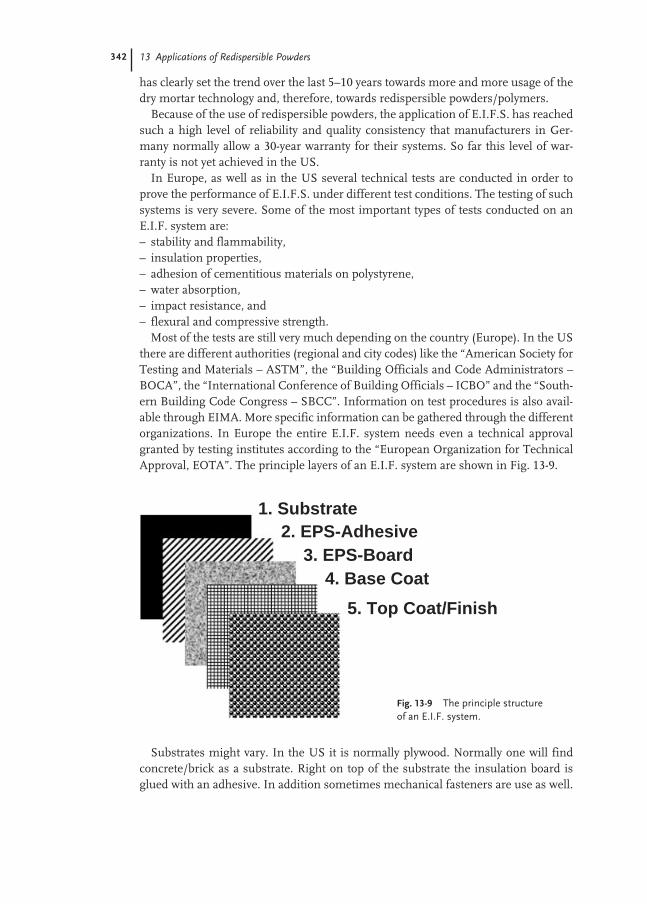
342 13 Applications of Redispersible Powders
has clearly set the trend over the last 5–10 years towards more and more usage of thedry mortar technology and, therefore, towards redispersible powders/polymers.
Because of the use of redispersible powders, the application of E.I.F.S. has reachedsuch a high level of reliability and quality consistency that manufacturers in Ger-many normally allow a 30-year warranty for their systems. So far this level of war-ranty is not yet achieved in the US.
In Europe, as well as in the US several technical tests are conducted in order toprove the performance of E.I.F.S. under different test conditions. The testing of suchsystems is very severe. Some of the most important types of tests conducted on anE.I.F. system are:– stability and flammability,– insulation properties,– adhesion of cementitious materials on polystyrene,– water absorption,– impact resistance, and– flexural and compressive strength.
Most of the tests are still very much depending on the country (Europe). In the USthere are different authorities (regional and city codes) like the “American Society forTesting and Materials – ASTM”, the “Building Officials and Code Administrators –BOCA”, the “International Conference of Building Officials – ICBO” and the “South-ern Building Code Congress – SBCC”. Information on test procedures is also avail-able through EIMA. More specific information can be gathered through the differentorganizations. In Europe the entire E.I.F. system needs even a technical approvalgranted by testing institutes according to the “European Organization for TechnicalApproval, EOTA”. The principle layers of an E.I.F. system are shown in Fig. 13-9.
Substrates might vary. In the US it is normally plywood. Normally one will findconcrete/brick as a substrate. Right on top of the substrate the insulation board isglued with an adhesive. In addition sometimes mechanical fasteners are use as well.
1. Substrate2. EPS-Adhesive
3. EPS-Board4. Base Coat
5. Top Coat/Finish
Fig. 13-9 The principle structure of an E.I.F. system.

13.4 Markets and Application Areas of Redispersible Powders 343
85 % of the insulation material used in Germany is Extruded Polystyrene “EPS”. TheEPS adhesive is normally the same material as the base coat. The functionality of thebase coat is protection and reinforcement of the EPS panel. Without polymer modi-fication there would be no adhesion of the EPS to the substrate and no adhesion ofthe base coat to the EPS panel. Besides adhesion, the right polymer modification be-comes also very important when impact resistance, water absorption or deformationcapability (flexibility) is tested. The base coat has an important functionality withinthe entire system. The right modification of the base coat with at least 3 to 6 % redis-persible powder will finally guarantee good performance values and as a conse-quence contribute to an excellent weather stability of the entire system. The integrityof the base coat, meaning a crack free base coat, is a precondition for good technicalperformance. For that purpose the polymer-to-cement ratio should be as high aspossible. This is one of the main differences between Europe and US . Normally thecement content in US systems is higher than in Europe. Assuming the polymercontent is very similar, this results in a higher polymer-to-cement ratio in Europeansystems compared to US systems. This has to do with the fact that the preference inEurope is towards more flexible system where else in the US a hard surface appear-ance of the base coat is preferred by contractors.
Certainly as important as the base coat is the topcoat for the entire system. Herewe find probably the biggest difference between, for example, Germany and theUnited States. In the US cementitious topcoats are almost not used at all. They aresynthetic, cement free systems that are very often ready to use and based on emul-sion technology. In Europe, as with Germany, topcoats are cement based as well.
Top/finish coats must meet certain critical physical and technical requirements.These include:– good adhesion to the substrate (tensile adhesion strength),– low water absorption or water repellency (hydrophobicity),– good drying characteristic (high water vapor permeability),– low susceptibility to cracking (good relaxation properties, flexibility),– the modulus of elasticity of the top coat should be lower than the modulus of elas-
ticity of the substrate (layer below),– resistance to weathering,– mechanical stability (high impact resistance),– low dirt pick up,– very low flammability.
(Finish or topcoats can also be named render, plaster or stucco. Normally slightdifferences apply, for example in thickness of the coating depending on the technol-ogy used. As far as the use of redispersible powder is concerned, they can be consid-ered equivalent.)
The addition of organic polymeric binders in form of redispersible powders tomineral plasters and stuccos can significantly enhance certain properties, such asadhesion to the substrate, mechanical resistance, low water absorption (hydrophobiceffect by using special redispersible powders) and long-term durability. In order tomeet these requirements the preferred redispersible powders used in topcoats arevinyl acetate/ethylene copolymers. Especially when it comes to flammability vinyl
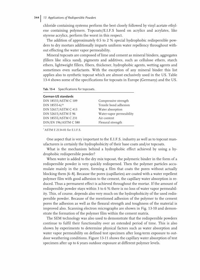
344 13 Applications of Redispersible Powders
chloride containing systems perform the best closely followed by vinyl acetate ethyl-ene containing polymers. Topcoats/E.I.F.S based on acrylics and acrylates, likestyrene acrylics, perform the worst in this respect.
The addition of approximately 0.5 to 2 % special hydrophobic redispersible pow-ders to dry mortars additionally imparts uniform water repellency throughout with-out effecting the water vapor permeability.
Mineral topcoats are composed of lime and cement as mineral binders, aggregates(fillers like silica sand), pigments and additives, such as cellulose ethers, starchethers, lightweight fillers, fibers, thickener, hydrophobic agents, wetting agents andsometimes even surfactants. With the exception of any mineral binder this list applies also to synthetic topcoat which are almost exclusively used in the US. Table13-4 shows some of the specifications for topcoats in Europe (Germany) and the US.
One aspect that is very important to the E.I.F.S. industry as well as to topcoat man-ufacturers is certainly the hydrophobicity of their base coats and/or topcoats.
What is the mechanism behind a hydrophobic effect achieved by using a hy-drophobic redispersible powder?
When water is added to the dry mix topcoat, the polymeric binder in the form of aredispersible powder is very quickly redispersed. Then the polymer particles accu-mulate mainly in the pores, forming a film that coats the pores without actuallyblocking them [6–8]. Because the pores (capillaries) are coated with a water repellentpolymer film with good adhesion to the cement, the capillary water absorption is re-duced. Thus a permanent effect is achieved throughout the mortar. If the amount ofredispersible powder stays within 3 to 6 % there is no loss of water vapor permeabil-ity. This, of course, depends also very much on the hydrophobicity of the used redis-persible powder. Because of the mentioned adhesion of the polymer to the cementpores the adhesion as well as the flexural strength and toughness of the material isimproved also. Scanning electron micrographs are shown in Fig. 13-10 and demon-strate the formation of the polymer film within the cement matrix.
The SEM technology was also used to demonstrate that the redispersible powderscontinue to fulfil their functionality over an extended period of time. This is alsoshown by experiments to determine physical factors such as water absorption andwater vapor permeability on defined test specimen after long-term exposure to out-door weathering conditions. Figure 13-11 shows the capillary water absorption of testspecimen after up to 6 years outdoor exposure at different polymer levels.
Tab. 13-4 Specifications for topcoats.
German-US standardsDIN 18555/ASTM C 109 Compressive strengthDIN 18555-6/* Tensile bond adhesionDIN 52617/ASTM C 413 Water absorptionDIN 52615/ASTM E 96 Water-vapor permeabilityDIN 18555/ASTM C 231 Air contentDIN/EN 196/ASTM C 580 Flexural strength
*ASTM E 2134-01 for E.I.F.S.

13.4 Markets and Application Areas of Redispersible Powders 345
13.4.4
Self-leveling Underlayments
The area of self-leveling underlayments (SLU) is out of a technical perspective prob-ably the most complex one if it comes to applications of redispersible powders. On agiven uneven substrate (i.e. screed or surface to be refurbished), self-leveling mor-tars have to provide a suitable, smooth and solid substrate in order to apply all kindof flooring materials like carpets, wood parquet, PVC, tiles etc. Self-leveling under-layments should be applicable in an easy and efficient manner, even for large areas.
Fig. 13-10 SEM of polymerfilm in cement matrix.
Fig. 13-11 Long-term performance of cementitious topcoats.
Capillary water absorption of mineral topcoat - long term exposure
0
0.5
1
1.5
2
2.5
3
3.5
4
0.5% 1.0% 2.0% 3.0% 3.5%
percentage redispersible powder on total formulation
wat
er a
bso
rpti
on
co
effi
cien
t ac
cord
ing
to
DIN
526
17
21 days standard conditions 1 year outdoor exposure 6 years outdoor exposure
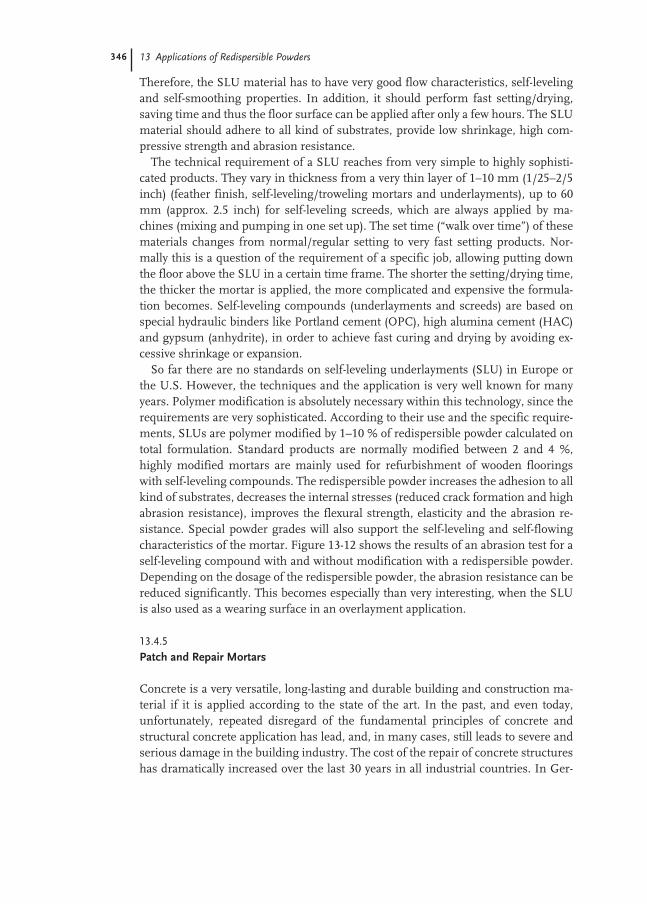
346 13 Applications of Redispersible Powders
Therefore, the SLU material has to have very good flow characteristics, self-levelingand self-smoothing properties. In addition, it should perform fast setting/drying,saving time and thus the floor surface can be applied after only a few hours. The SLUmaterial should adhere to all kind of substrates, provide low shrinkage, high com-pressive strength and abrasion resistance.
The technical requirement of a SLU reaches from very simple to highly sophisti-cated products. They vary in thickness from a very thin layer of 1–10 mm (1/25–2/5inch) (feather finish, self-leveling/troweling mortars and underlayments), up to 60mm (approx. 2.5 inch) for self-leveling screeds, which are always applied by ma-chines (mixing and pumping in one set up). The set time (“walk over time”) of thesematerials changes from normal/regular setting to very fast setting products. Nor-mally this is a question of the requirement of a specific job, allowing putting downthe floor above the SLU in a certain time frame. The shorter the setting/drying time,the thicker the mortar is applied, the more complicated and expensive the formula-tion becomes. Self-leveling compounds (underlayments and screeds) are based onspecial hydraulic binders like Portland cement (OPC), high alumina cement (HAC)and gypsum (anhydrite), in order to achieve fast curing and drying by avoiding ex-cessive shrinkage or expansion.
So far there are no standards on self-leveling underlayments (SLU) in Europe orthe U.S. However, the techniques and the application is very well known for manyyears. Polymer modification is absolutely necessary within this technology, since therequirements are very sophisticated. According to their use and the specific require-ments, SLUs are polymer modified by 1–10 % of redispersible powder calculated ontotal formulation. Standard products are normally modified between 2 and 4 %,highly modified mortars are mainly used for refurbishment of wooden flooringswith self-leveling compounds. The redispersible powder increases the adhesion to allkind of substrates, decreases the internal stresses (reduced crack formation and highabrasion resistance), improves the flexural strength, elasticity and the abrasion re-sistance. Special powder grades will also support the self-leveling and self-flowingcharacteristics of the mortar. Figure 13-12 shows the results of an abrasion test for aself-leveling compound with and without modification with a redispersible powder.Depending on the dosage of the redispersible powder, the abrasion resistance can bereduced significantly. This becomes especially than very interesting, when the SLUis also used as a wearing surface in an overlayment application.
13.4.5
Patch and Repair Mortars
Concrete is a very versatile, long-lasting and durable building and construction ma-terial if it is applied according to the state of the art. In the past, and even today,unfortunately, repeated disregard of the fundamental principles of concrete andstructural concrete application has lead, and, in many cases, still leads to severe andserious damage in the building industry. The cost of the repair of concrete structureshas dramatically increased over the last 30 years in all industrial countries. In Ger-

13.4 Markets and Application Areas of Redispersible Powders 347
many approximately 20 % of the cost of the volume of structural concrete work is at-tributed to the repair and maintenance of existing buildings and structures.
The degradation of structural concrete is caused by corrosion of the steel rein-forcement due to chemical processes, which often occur over a long period of time.One of the main reasons is the carbonation of concrete. Acidic carbon dioxide (CO2)from the atmosphere and other aggressive media (such as SO2, acid rain) neutralizesthe alkalinity of the concrete. Once the alkaline environment of the steel reinforcingno longer exists, the steel starts to corrode and, due to its volume increase, causessplitting of the concrete on top of the steel reinforcement. A secondary cause of cor-rosion is the penetration of free chloride ions into the concrete, leading to chlorideion attack on the steel.
Fig. 13-12 Abrasion resistance with and without redispersible powder.

348 13 Applications of Redispersible Powders
In the construction industry concrete repair work can be classified in two types:– concrete repair, which does not contain steel reinforcement and which does not
have load-bearing functions. The repair is normally done for aesthetic reasons(cosmetic repair work) only, with namely patching mortars/compounds
– repair and reconstruction of damaged reinforced and load-bearing concrete struc-tures, in order to maintain and reconstitute their structural stability. This is donein stages with different kind of mortars, which are part of a “concrete rehabilita-tion system” (typical applications: repair work and rehabilitation of bridges, park-ing decks, tunnels, etc).Patching mortars for re-profiling and cosmetic repair are mainly based on dry mix
mortars and are not part of an entire repair or rehabilitation system. Usually, ce-ment-based mortars are used for indoor and outdoor applications, whereas gypsum-based products are only used for some specific indoor applications (cosmetic repair).Patching mortars are used to repair defective or damaged areas of mineral surfaceswithout taking on a load bearing function, i.e. for filling small holes, voids, cracksand cavities in order to restore the original dimension. Typical applications arepatching mortars for walls, ceilings, floors, steps of staircases, etc. These mortarsmust have the following characteristics:– good workability,– easy to apply,– good adhesion to all construction substrates,– high durability and abrasion/wear resistance, if exposed to direct wear/load,– sufficient flexibility to reduce the risk of crack formation,– low shrinkage, and– water repellence for outdoor applications.
To meet the required technical criteria, these patching mortars are applied as apolymer modified pre-packed dry mix mortar. Polymer modification with redis-persible powder will – depending on the dosage – improve the:– workability of the mortar,– wetting capability of the substrate,– adhesion to all kind of substrates,– flexural strength,– abrasion resistance,– flexibility (lower modulus of elasticity than substrate),– durability, and– water repellent effect by using special grades of hydrophobic redispersible pow-
ders.To be able to guarantee the durable and reliable repair of structural concrete, three
main fundamental requirements of a concrete rehabilitation system must be ful-filled simultaneously:– restoration of the corrosion protection of the steel reinforcement (alkaline envi-
ronment),– restoration and re-profiling of the concrete structure including its load-bearing
functions, and

13.4 Markets and Application Areas of Redispersible Powders 349
– restoration of the durability of the whole construction (protection against weather-ing and environmental damage caused by CO2, SO2, Cl2, salts, etc.).Today, polymer modified cement concrete (PCC) mortars, which can be applied by
hand, in a wet or even a dry spraying process, are usually used for the rehabilitationof concrete structures. Different kind of mortars with different characteristics andfunctions are used as the components for concrete rehabilitation systems:– primer and adhesion promoter for the reinforced steel (polymer modified cemen-
titious slurry or epoxy based coating materials),– adhesion promoter slurry (primer or key-coat) for the concrete to be repaired (poly-
mer modified cement based slurry),– restoration and re-profiling mortar (polymer modified cement based mortar),– fine stopper or smoothing mortar (polymer modified cement based mortar con-
taining fine aggregate), and– protection and finish coat (dispersion paints, crack over bridging paints, cementi-
tious waterproofing sealing slurries, etc.).The improvement of adhesion to concrete and steel, using a polymer modified re-
profiling mortar, with and without applying a cementitious primer, is demonstratedin Fig. 13-13; Fig. 13-14 shows the improvement in flexural strength of a typical re-profiling mortar applied by hand with and without different grades of redispersiblepowder.
The flexural strength of the mortar is already significantly improved by addingonly 2 % of redispersible powder without affecting the compressive strength toomuch.
Fig. 13-13 Adhesion to concrete and steel with and without primer.
Tensile bond adhesion after 28 d standard conditions polymer/cement ratio = 0.07
0
0.5
1
1.5
2
2.5
3
over concrete over steel
Ten
sile
ad
hes
ion
[N
/mm
2]
without primer with primer
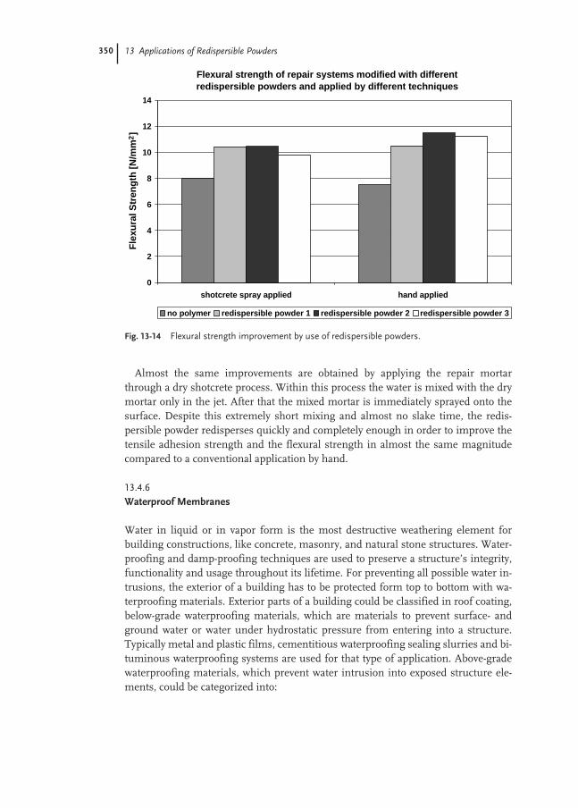
350 13 Applications of Redispersible Powders
Almost the same improvements are obtained by applying the repair mortarthrough a dry shotcrete process. Within this process the water is mixed with the drymortar only in the jet. After that the mixed mortar is immediately sprayed onto thesurface. Despite this extremely short mixing and almost no slake time, the redis-persible powder redisperses quickly and completely enough in order to improve thetensile adhesion strength and the flexural strength in almost the same magnitudecompared to a conventional application by hand.
13.4.6
Waterproof Membranes
Water in liquid or in vapor form is the most destructive weathering element forbuilding constructions, like concrete, masonry, and natural stone structures. Water-proofing and damp-proofing techniques are used to preserve a structure’s integrity,functionality and usage throughout its lifetime. For preventing all possible water in-trusions, the exterior of a building has to be protected form top to bottom with wa-terproofing materials. Exterior parts of a building could be classified in roof coating,below-grade waterproofing materials, which are materials to prevent surface- andground water or water under hydrostatic pressure from entering into a structure.Typically metal and plastic films, cementitious waterproofing sealing slurries and bi-tuminous waterproofing systems are used for that type of application. Above-gradewaterproofing materials, which prevent water intrusion into exposed structure ele-ments, could be categorized into:
Fig. 13-14 Flexural strength improvement by use of redispersible powders.
Flexural strength of repair systems modified with different redispersible powders and applied by different techniques
0
2
4
6
8
10
12
14
shotcrete spray applied hand applied
Fle
xura
l Str
eng
th [
N/m
m2]
no polymer redispersible powder 1 redispersible powder 2 redispersible powder 3

13.4 Markets and Application Areas of Redispersible Powders 351
– decorative and finishing barrier systems, i.e. all kinds of paints;– mineral topcoats (renders, plasters);– damp-proofing materials, which reduce or prevent water vapor transmission
through building materials and are not subjected to weathering or water pressure(water vapor barrier foils); and
– flashings, materials or systems installed to direct water entering through the wallcladding back to the exterior like metal foils in walls to prevent capillary water up-take.All waterproofing has to be part of a whole system and must interact integrally to
reach complete effectiveness and to prevent water infiltration. In case one of thesesystem parts fails or does not perform with all other protection systems, leakage willoccur. Adequately controlling groundwater, rainwater and surface water, as well asthe transport of humidity in the form of water vapor will avoid unnecessary repairs tobuilding’s exterior or its damage or even destruction (deterioration). Apart from pro-tecting the exterior of building constructions, there is a multiplicity of waterproofingmaterials for interior use. Some of the waterproofing materials are used to protectagainst the detrimental action of aggressive substances like salts and acids transport-ed by the water.
Traditional sealing and waterproofing systems, i.e. according to the German stan-dard DIN 18195, include bituminous materials, plastic waterproofing foils and met-al tapes for interior and exterior applications. Different types of materials can beused in order to seal and protect the surface of buildings or its structural compo-nents against the intrusion of dampness and water. Nowadays products for that pur-pose are based on reactive resins like epoxy and/or polyurethane, dispersions(paintable waterproofing membranes) and mineral binders like cement, which areknown as waterproofing membranes or sealant slurries.
Cementitious waterproofing membranes have been successfully used for morethan 40 years in Europe for protection of a wide range of building structures andstructural components. The structures were either exposed to periodically or long-term wettings (surface water, seepage water), low hydrostatic pressure (soil damp-ness) or in combination with appropriate engineering even high hydrostatic pres-sure. Cementitious membranes (slurries) are used to waterproof wet rooms andwater tanks, and due to their excellent weathering resistance they are also used forexterior surface protection. Further typical applications are the sealing and water-proofing of basement walls, swimming pools, walls and floors, in bathrooms, on bal-conies and porches (as a waterproofing layer to be tiled over). Especially in the case ofa tile application these slurries can also act as crack isolation membranes. In addi-tion, flexible, cementitious waterproofing membranes are often used as a protectivesurface-coating system for structural concrete (i.e. protection of reinforced structuralconcrete within new structures as well as for concrete structures after restoration). Itis applied for the protection against penetration of water, chlorides and free carbondioxide in order to avoid corrosion of the reinforcing metal and can provide a protec-tive layer to a building against aggressive chemicals (sulfates, acids, i.e. in waste-wa-ter drains). Some of the advantages of cement-based waterproofing membranes are:
352 13 Applications of Redispersible Powders
– excellent resistance against water, even if exposed permanently;– excellent resistance against long term weathering;– good scratch resistance;– good load-carrying capacity; and– much higher water vapor permeability compared to most of the other systems.
Consequently there are no problems with blistering since water vapor passesthrough the membrane.Cement-based waterproofing slurries are easy to use, non toxic, provide a fully
bound and monolithic surface without joints and can be easily applied on substrateswith complex surface shapes. In contrast to other systems, cementitious waterproof-ing slurries can even be used on damp and wet mineral surfaces. Their physicalproperties are also less temperature dependent compared to bitumen based materi-als.
Simple, non-polymer modified cement based slurries are still used for the protec-tion against surface water, but they are not suitable to seal against water under hy-drostatic pressure. In order to improve the poor adhesion, the poor water tightness,and the extremely low deformability or flexibility of these non modified systems,polymers are added in form of liquid dispersions on the job-site or in form of a re-dispersible powder already mixed in the dry mix mortar. The use of special additivesin the dry mix mortars like water retention agents, thickening agents and rheologicaladditives in combination with the polymeric binder, the redispersible powder, pro-vide an excellent workability and make sure that there is no need for a post water-treatment of the applied slurry.
Today, in principle, two different systems of cementitious waterproofing mem-branes or slurries are available:1. Standard or rigid mineral waterproofing slurries, which are polymer-modified,
pre-packed dry mix mortars containing approx. 3 to 6 % of redispersible powder.They are used for mineral substrates, which are stable, sound and solid. Thereshould be no risk for crack formation, movements or dimensional changes likeshrinkage.
2. Flexible and highly flexible cementitious waterproofing slurries (as two-compo-nent or one-component systems).In addition to the traditional, rigid waterproof membranes, developments in the
late 1970s led in Europe to flexible waterproofing slurries, which are to a certain ex-tend capable to over-bridge small cracks (up to approx. 1 mm) in the substrate. Theflexibility of such products strongly depends on the polymer/cement ratio and cer-tainly also on the flexibility of the polymer itself. Flexible and highly flexible water-proofing cementitious slurries are used on substrates still undergoing shrinkage, vi-brations, movements, stresses, crack formation and on substrates difficult to be coat-ed like wood, steel, aerated light weight blocks and gypsum. Due to their high poly-mer content (up to 25–40 % on total formulation), they are diffusion and chemicallyresistant against chloride, sulfate ions and carbon dioxide or other aggressive mate-rials.
Thus far these flexible cement based waterproofing, sealing slurries have beenmainly used as two-component systems (liquid dispersion/emulsion added to the

13.5 Summary 353
pre-packed dry mix). But due to the many disadvantages of modifying mortars withliquid dispersions on a job-site, in modern construction technique more and morethe one-component, flexible cementitious slurries, modified with high dosages ofspecial redispersible powders are used. These one-component, premixed polymer-modified dry mix mortars are offering advantages as they were already discussedwithin this chapter.
13.5
Summary
The need for new construction methods and building materials, that are safely, reli-ably, efficiently and economically to apply, promotes modern technologies like the“dry mix mortar technology”. Redispersible powders make the production of com-plete pre-manufactured high quality mortars (“bagged mortars”) possible. As a con-sequence, job-site mix technology and job-site modification of mortars with liquidpolymers is being replaced all over the world. Especially since product characteristicscan be specifically designed for modern construction requirements and climate con-ditions by using dry mix mortars.
Dry mix mortars modified with redispersible powders provide a significantly im-proved productivity on the construction site. They allow a high degree of rationaliza-tion coupled with an easy, rapid, more efficient and safer handling and processing ofthe product. This eliminates onsite mixing errors and ensures, consistently, excel-lent results. The quality of the workmanship is consistent on a high level thus im-proving the warranty status of a construction job dramatically.
Dry mix mortars, mainly based on cement but also on gypsum, that are modifiedwith redispersible powders have been successfully used for many decades all overthe world. The most typical applications are:– ceramic tile adhesives,– tile grout mortars,– mortars for the thermal insulation systems,– stuccos, skim-coats and finishing renders,– patch and repair mortars,– self-leveling under- and overlayments,– waterproofing sealing slurries (membranes),– joint compounds, and– powder paints.
The modification of dry mix mortars with dry polymers in the form of redis-persible powders also significantly improves the technical performance of the mor-tars. The combination of the mineral binder with a polymeric binder in the form ofan redispersible powder in dry mix mortars guarantees outstanding synergistic prop-erties and characteristics, which cannot be achieved by either of the binders alone.The sufficient modification of mineral dry mix mortars by redispersible powders willimprove workability, adhesion to various substrates, flexibility and deformability of

354 13 Applications of Redispersible Powders
the mortars, abrasion resistance, density (impermeability), flexural and cohesivestrength and the long-term durability.
Manufacturers, contractors, applicators and end-users (“Do it yourself” market) allbenefit significantly from dry mix mortars modified with redispersible powders.That technology almost exclusively makes machine applications, which becomemore and more popular with all kinds of construction materials, possible.
References
1 Research report No. 13 of “Vereinigungvon Systembouwers van de WerkgroepSA 5, Tegels, Het vermijden van Schadeaan gelijmd Wandtegelwerk”; March1975, Vereinigung von Systembouwers,Gravenhage, Netherlands.
2 Publications of G. Wesseling (TNO Insti-tute, Netherlands); in TonindustrieZeitung No. 8 1971, 95, 211.
3 Research report B II 5 – 800177-118; “Ermittlung des Verformungsverhaltensvon Duennbettmoerteln bzw. Klebstof-fen fuer keramische Fliesen”; August1979 von Prof. Dr. Kirtschig; TechnischeUniversitaet Hannover.
4 Rapport “Lim for keramiske fliser; methode for proving av even tile aoverfore relative bewegelser mellomunderlag og fliser (flexksibilitet)” von BYGGFORSK, Norwegisches Baufor-schungsinstitut, Forskningsveien 3 b;Postboks 123 Blindern, 0314 Oslo 3,Projekte E 3593, Trondheim04/08/1992.
5 Fox T.J.; Bull. Am. Phys. Soc. 1956, 1, 23.6 Schulze, J.; Tonindustrie-Zeitung 1985,
109, 698. 7 Schulze, J.; Beton 1991, 5, 232.8 Adler, K.; Schweizer Baublatt 1988, 31,
44.

355
14
Applications for Modification of Plastic Materials
Chuen-Shyong Chou and Jane E. Weier
14.1
Introduction
The global plastics industry is growing rapidly with an annual average rate of 4–6 %.This is primarily due to the fact that plastics continue to replace traditional materialssuch as metals, wood, and minerals. In a very dynamic market such as building andconstruction, the compounded annual growth rate (CAGR) of plastics was about7–8 % between 1992 and 1997. In the same period of time, PVC poly(vinyl chloride),accounted for more than half of the plastics consumption in the segment, achievingCAGR of 9 % [1]. The successful application of plastic materials has substantially en-abled the incorporation of additives to the resins. Amongst the numerous additivesused, polymeric impact modifiers and process aids provide some of the most uniqueand valued performance and processing enhancements [2, 3]. Toughening, rheologycontrol, aesthetics, processing, and economics are the major performance attributes.These additives have been around for many years, and they have evolved over thattime into a broad array of product offerings. A key reason is the versatility of emul-sion polymerization, which enables scientists to design proper polymer composi-tion, polymer structure, polymer morphology, and polymer molecular weight/molecular weight distribution. Emulsion polymerization is commercially attractivebecause of the low manufacturing cost and ease of isolation for the resulting latexproducts.
The first polymeric additives produced using emulsion polymerization technologywere core-shell impact modifiers made of methacrylate–butadiene–styrene (MBS),which were introduced in 1956. These were followed by all-acrylic process aids andacrylic impact modifiers [4, 5]. The additives were originally aimed at improvementsin PVC processing capability and toughness. Nevertheless, the application has beenextended to polyolefin and many engineering resins such as nylon, polycarbonate,and polyesters. In addition to toughening of thermoplastic matrices, core-shell im-pact modifiers were also applied to fracture toughening of thermoset resins such asepoxy and unsaturated polyesters [6–11]. Processing aids are mainly applied to a PVCcompound for fusion promotion, melt strength, dispersion and surface quality. Ultra

356 14 Applications for Modification of Plastic Materials
high molecular weight processing aids are critical components in foamed PVC. Withthe help of the processing aid, more uniform cell structures with less rupture andlower foam density can be achieved. Lubricating type processing aids prevent themelt plastic from sticking to metal surface, improve surface quality, and increaseproductivity. In addition to PVC, polymeric processing aids are becoming popular inother thermoplastics for certain limited applications.
In addition to impact modifiers and processing aids, a number of polymeric mod-ifiers have been promoted for controlling gloss, improving heat distortion tempera-ture (HDT), enhancing compatibility in polymer alloys, broadening the thermoform-ing window, controlling light diffusion and optical properties, and improving theplastic and cellulose composites processing. These polymeric modifiers offer someunique properties and many of the developments are also tied closely to emulsionpolymerization technology.
14.2
Emulsion Polymerization and Isolation Technology
A comprehensive description of emulsion polymerization chemistry can be found in books written by Gilbert [12] and Lovell and El-Aasser [13] and Blackley [14]. Although the process appears straightforward, the technology is extremely compli-cated. Several possible polymerization loci can be present simultaneously includingthe aqueous phase, micelles, monomer droplets, particle-water interface, and latexparticles. Emulsion polymerization techniques are in wide commercial use becauseof their many advantages; however, the process is not without its drawbacks. Themajor advantages include:– The rate of polymerization is usually considerably greater than in a bulk process.– An emulsion polymerization can easily achieve a relatively high conversion of
monomer to polymer; hence any problems with residual monomer are minimizedand monomer consumption is maximized.
– The polymer usually has a considerably higher average molecular weight than thatfrom a solution polymerization or bulk process, and has a different molecularweight distribution. The polymer molecular weight can be controlled with appro-priate initiator and reaction conditions.
– Because the molecular weight is very high in the absence of chain-transfer agents,molecular weight is easily controlled by the addition of chain-transfer agents, andallows for additional control of the properties.
– Various polymer morphologies with different molecular structures and molecularweights can be achieved with a multiple-stage process. It is possible to control themorphology of the system with layers, lobes or isolated domains of specific com-position.A core-shell impact modifier is probably the best model to illustrate the utility of
emulsion polymerization technology. The core polymer is based on a low glass tran-sition temperature (Tg) rubber and is surrounded by a hard polymeric shell (high Tg
material). The core rubber is made in the first stage of the emulsion polymerization,
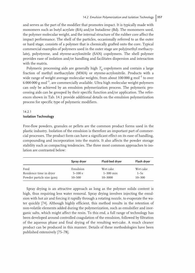
14.2 Emulsion Polymerization and Isolation Technology 357
and serves as the part of the modifier that promotes impact. It is typically made withmonomers such as butyl acrylate (BA) and/or butadiene (Bd). The monomers used,the polymer molecular weight, and the internal structure of the rubber core affect theimpact performance. The shell of the particles, occasionally referred to as the outeror hard stage, consists of a polymer that is chemically grafted onto the core. Typicalcommercial examples of polymers used in the outer stage are poly(methyl methacry-late), polystyrene, and styrene-acrylonitrile (SAN) copolymers. The shell polymerprovides ease of isolation and/or handling and facilitates dispersion and interactionwith the matrix.
Polymeric processing aids are generally high Tg copolymers and contain a largefraction of methyl methacrylate (MMA) or styrene-acrylonitrile. Products with a wide range of weight average molecular weights, from about 100 000 g mol–1 to over6 000 000 g mol–1, are commercially available. Ultra high molecular weight polymerscan only be achieved by an emulsion polymerization process. The polymeric pro-cessing aids can be grouped by their specific function and/or application. The refer-ences shown in Tab. 14.1 provide additional details on the emulsion polymerizationprocess for specific type of polymeric modifiers.
14.2.1
Isolation Technology
Free-flow powders, granules or pellets are the common product forms used in theplastic industry. Isolation of the emulsion is therefore an important part of commer-cial processes. The product form can have a significant effect on its ease of handling,compounding and incorporation into the matrix. It also affects the powder storagestability such as compacting tendencies. The three most common approaches to iso-lation are contrasted below:
Spray drying is an attractive approach as long as the polymer solids content ishigh, thus requiring less water removal. Spray drying involves injecting the emul-sion with hot air and forcing it rapidly through a rotating nozzle, to evaporate the wa-ter quickly [74]. Although highly efficient, this method results in the retention ofnon-volatile elements added during the polymerization, such as emulsifier and inor-ganic salts, which might affect the resin. To this end, a full range of technology hasbeen developed around controlled coagulation of the emulsion, followed by filtrationof the aqueous phase and final drying of the resulting wet-cake. A much cleanerproduct can be produced in this manner. Details of these methodologies have beenpublished extensively [75–78].
Spray dryer Fluid-bed dryer Flash dryer
Feed Emulsion Wet cake Wet cakeResidence time in dryer 5–100 s 1–300 min 1–5sPowder particle size (µm) 10–500 10–3000 10–300
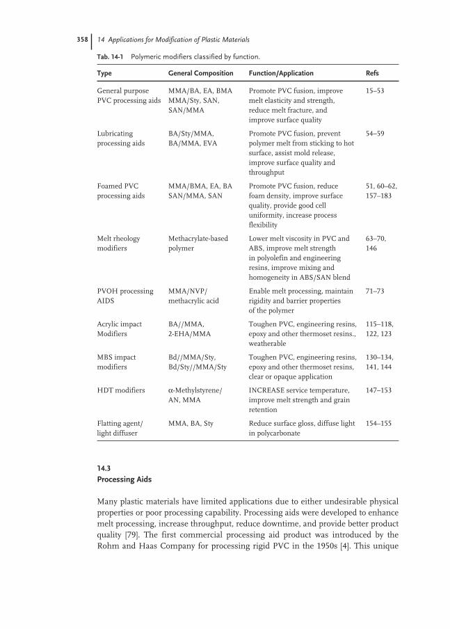
358 14 Applications for Modification of Plastic Materials
14.3
Processing Aids
Many plastic materials have limited applications due to either undesirable physicalproperties or poor processing capability. Processing aids were developed to enhancemelt processing, increase throughput, reduce downtime, and provide better productquality [79]. The first commercial processing aid product was introduced by theRohm and Haas Company for processing rigid PVC in the 1950s [4]. This unique
Tab. 14-1 Polymeric modifiers classified by function.
Type General Composition Function/Application Refs
General purpose MMA/BA, EA, BMA Promote PVC fusion, improve 15–53PVC processing aids MMA/Sty, SAN, melt elasticity and strength,
SAN/MMA reduce melt fracture, and improve surface quality
Lubricating BA/Sty/MMA, Promote PVC fusion, prevent 54–59processing aids BA/MMA, EVA polymer melt from sticking to hot
surface, assist mold release, improve surface quality and throughput
Foamed PVC MMA/BMA, EA, BA Promote PVC fusion, reduce 51, 60–62,processing aids SAN/MMA, SAN foam density, improve surface 157–183
quality, provide good cell uniformity, increase process flexibility
Melt rheology Methacrylate-based Lower melt viscosity in PVC and 63–70, modifiers polymer ABS, improve melt strength 146
in polyolefin and engineering resins, improve mixing and homogeneity in ABS/SAN blend
PVOH processing MMA/NVP/ Enable melt processing, maintain 71–73AIDS methacrylic acid rigidity and barrier properties
of the polymer
Acrylic impact BA//MMA, Toughen PVC, engineering resins, 115–118, Modifiers 2-EHA/MMA epoxy and other thermoset resins., 122, 123
weatherable
MBS impact Bd//MMA/Sty, Toughen PVC, engineering resins, 130–134, modifiers Bd/Sty//MMA/Sty epoxy and other thermoset resins, 141, 144
clear or opaque application
HDT modifiers α-Methylstyrene/ INCREASE service temperature, 147–153AN, MMA improve melt strength and grain
retention
Flatting agent/ MMA, BA, Sty Reduce surface gloss, diffuse light 154–155light diffuser in polycarbonate

14.3 Processing Aids 359
technology was well acknowledged and led to the surge of the PVC industry. Similardevelopment efforts have been applied to other thermoplastic materials and polymerblends since the 1980s. Although processing aids are generally added to PVC andother thermoplastics in small quantity (0.5–5 %), they dramatically alter the process-ing characteristics without a substantial effect on other application properties. Pro-cessing aids can be classified by functions such as fusion promotion, melt rheologymodification, lubrication, and dispersion promotion. Each processing aid mayprovide more than one function. The function and performance of a specific type ofprocessing aid is affected by the chemical composition, polymer architecture, poly-mer molecular weight, and the matrix type.
14.3.1
Processing Aids for PVC
In a thermoplastic resin, to the mechanical properties of the final product are related to the homogeneity of the polymer melt during the conversion process. Unlike themajority of other thermoplastic resins, rigid PVC is not processable due to its inher-ent particulate structure. It requires a long processing time at high temperatureswhich leads to thermal degradation. The history and development of processing aidsfor PVC, as well as the proposed mechanism are well documented [3, 5]. Processingaids offer several benefits to a PVC formulation, mainly related to the fusion andmelt rheology during processing [3]. Processing aids help to increase cohesion andhomogeneity of the melt, melt strength, melt extensibility, and elasticity. The com-position and the polymer structure of the processing aid affects the compatibilitywith PVC and alters properties such as fusion promotion and lubrication. On theother hand, the molecular weight and molecular weight distribution play the majorrole in controlling the melt rheology. The most common processing aids are methylmethacrylate based polymers. PMMA based polymers have a high glass transitiontemperature (Tg) and are also extremely compatible with PVC [80, 81], which help tocreate and transfer localized shear heat to melt the PVC during fusion process.
Improving melt rheology, increasing dispersibility, improving efficiency, andenhancing the overall balance of properties, (especially melt strength versus viscosi-ty) have been the major goals of new processing aid development [82]. This has led tothe ability to get equal performance from lower levels of process aid, and, in the caseof clear applications, materials that disperse more rapidly with greater clarity.
Fusion promotion and melt homogeneityThe most common approach to characterize the PVC fusion process employs theBrabender® Plasticorder or Haake Rheometer, which consists of a mixing head withtwo rolls. Figure 14-1 shows the PVC fusion process as reflected in the curve offusion torque vs. time. The melt temperature in each stage can also be recorded.Point “A” is referred as the “compaction” peak and corresponds to compression anddensification of the powder. Point “B” refers to the beginning of melting, followed by the appearance of the fusion peak. Point “C” occurs as PVC fuses into melt. Thedifference in time between A and C is called “fusion time”. The torque observed at

360 14 Applications for Modification of Plastic Materials
point “C” is called the “fusion torque”. PVC is not completely melted at this stageand the majority of melt is in the form of sub-microscopic particles. The fusion con-tinues to occur as the torque drops down to an approximately constant value at point“D”, which is referred as the equilibrium torque. The equilibrium torque can be in-terpreted as a rough estimate of melt viscosity. As the heating and shearing contin-ue, dehydrochlorination and cross-linking of PVC chains can occur, producing thetorque increase at point “E”. The difference in time between A and E is called the“degradation time”. The fusion curve is strongly influenced by the formulation type,processing temperature, shear rate, and loading level.
Faster fusion time does not indicate complete breakdown of the PVC particulatestructure, and does not correlate well with good melt homogeneity. However, thesmoothness of rolling bank in the roll mill can provide a rough estimate. With only2 % acrylic processing aid in a tin-stabilized PVC (K-value = 61) at 180 °C. 180 °C pro-cessing temperature, the stock on the roll is clear, smooth, and homogeneous, andthe rolling bank is also smooth. In contrast, a non-homogeneous melt on the roll anda badly fractured rolling bank can be observed when no processing aid is added. Theresulting sheets of both processes are shown in Fig. 14-2. With processing aid, thesheet is strong, free of pinholes, and has no air streak and melt fracture. Theunmodified PVC film tears, crumbles, and loses its integrity. The PVC melt homo-geneity can be examined under a transmission electron microscope. A DifferentialScanning Calorimetry (DSC) method can help to assess the degree of PVC fusion.This technique provides the level of gelation and is related to the fusion of the PVCspecimen [83].
Fig. 14-1 Torque rheometry of a PVC compound,torque versus time.Time
A
B
C
D ETo
rqu
e

14.3 Processing Aids 361
Melt strength, extensibility, and elasticityMelt strength is a phenomenon reflecting both elasticity and elongational viscosity.Extensibility describes the PVC melt’s ability to undergo large elongation or stretch-ing deformation without rupture. Elasticity is related to the tendency to return to itsoriginal state when stresses are removed. It is difficult to separate these rheologicalproperties. A combination of tensile strength, elongation, and elasticity defines the“toughness” of a melt. Without polymeric processing aid, PVC would not withstandhigh stress or extension. The acrylic copolymers that are typically used as processingaids are generally compatible with PVC, and with their long chains, interact to pro-duce a stiffer and more elastic melt. Increased rupture stress and extensibility helpsthe PVC become far more resistant to rupture-induced defects.
Although the practical effects of melt strength are abundantly clear to the proces-sor, measuring the melt strength quantitatively is usually difficult. The GottfertRheotens is a device that uses a gear-like strain gauge – instrumental “puller” todraw a fully fused melt from a right-angled (vertical drop) extruder. While the ex-truder output rate is stabilized, the geared take-off accelerates until the melt (extru-date) breaks. Therefore, the rheological properties of the PVC melt can be recordedquantitatively. Die swell is another method for measuring melt elasticity. When apolymer is deformed, it tends to return to its original form after external force is re-moved. This behavior is commonly observed as the swelling of an extrudate as it ex-its the die. The degree of swelling is related to the polymer recoverable strain or elas-ticity and is normally expressed as swell ratio (extrudate diameter/die exit diameter)or by the comparison of the weight of a fixed length of extrudate. As shown inFig. 14-3, the extrudate weight is dependent upon the concentration of processingaid. As predicted, the die swell is related to the polymer molecular weight. Melt elas-ticity is an important factor in establishing melt stability as the melt enters and pro-
Fig. 14-2 A tin-stabilized PVC (K = 61) formulation was processed at 180 °C for 4 min.(A) Without the addition of processing aid, (B) With 2 phr of Paraloid K-125. The sheet (A)is hazy and has no film integrity. The sheet (B)is clear, strong and has a smooth surface.

362 14 Applications for Modification of Plastic Materials
ceeds through the die in extrusion. The higher die entry pressure observed whenprocessing aid is present is also a good indicator of higher melt elasticity [79].
One of the more recent advances in processing aids has been the development ofultra high molecular weight materials specifically designed for use in PVC foam ap-plications [84, 85]. With the help of a proper processing aid, the cell structure of anextruded foam is more uniform with lower rupture tendencies [86, 87]. The PVCmelt can withstand great extension before it breaks [88]. Therefore, a low densityfoam with fine cell structure and good surface quality can be achieved. As shown inFig. 14-4, an ultra high molecular weight processing aid with Mw = 8 × 10⁶ is about30 % more effective in terms of foam density, cell uniformity, and surface qualitycompared with a similar processing aid with the Mw = 6 × 10⁶. Without a proper pro-cessing aid, the foam can have large cells, poor surface structure, and gas contain-ment can be low (blow out). The effect of processing aid level on the surface qualityof a PVC foam rod is shown in Fig. 14-5.
Melt viscosityMany thermoplastic resins have excellent physical properties and high service tem-perature, which are often accompanied by high melt viscosity. High melt viscositymakes processing more difficult and often decreases productivity as well as productquality. Especially in injection molding, it is a major challenge for any material to fillthin walls, long flow paths, and/or complex shapes. Most high molecular weight pro-cessing aids increase the melt viscosity. However, it has been demonstrated that alow level of standard acrylic processing aid does not have a noticeable effect on meltviscosity [44, 89]. On the other hand, a combination of multi-function processingaids can balance the melt rheology and melt homogeneity. Rigid PVC compounds
Fig. 14-3 Effect of Processing Aid Molecular Weight and Concentration on Extrudate Weight. PVC formulation was based on 100 phr PVC (K = 57),1.5 phr Advastab TM-181, 0.5 phr ALDO MS and 0.2 phr OP Wax.
25
30
35
40
45
50
0 1 2 3 4 5 6
A : Mw = 1.5 millionB : Mw = 2.5 millionC : Mw = 3.5 millionD : Mw = 6 million
Processing Aid Level (phr)
Ext
rud
ate
We
igh
t (g
)
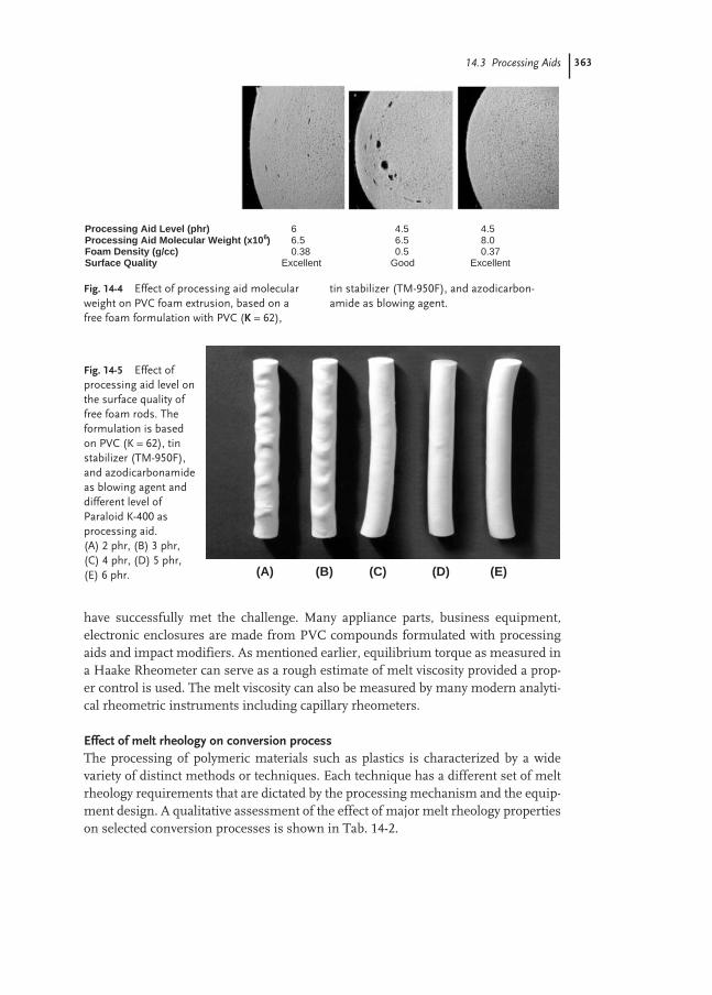
14.3 Processing Aids 363
have successfully met the challenge. Many appliance parts, business equipment,electronic enclosures are made from PVC compounds formulated with processingaids and impact modifiers. As mentioned earlier, equilibrium torque as measured ina Haake Rheometer can serve as a rough estimate of melt viscosity provided a prop-er control is used. The melt viscosity can also be measured by many modern analyti-cal rheometric instruments including capillary rheometers.
Effect of melt rheology on conversion processThe processing of polymeric materials such as plastics is characterized by a widevariety of distinct methods or techniques. Each technique has a different set of meltrheology requirements that are dictated by the processing mechanism and the equip-ment design. A qualitative assessment of the effect of major melt rheology propertieson selected conversion processes is shown in Tab. 14-2.
Fig. 14-4 Effect of processing aid molecularweight on PVC foam extrusion, based on a free foam formulation with PVC (K = 62),
tin stabilizer (TM-950F), and azodicarbon-amide as blowing agent.
Processing Aid Level (phr) 6 4.5 4.5Processing Aid Molecular Weight (x106) 6.5 6.5 8.0Foam Density (g/cc) 0.38 0.5 0.37 Surface Quality Excellent Good Excellent
Fig. 14-5 Effect ofprocessing aid level onthe surface quality offree foam rods. Theformulation is basedon PVC (K = 62), tinstabilizer (TM-950F),and azodicarbonamideas blowing agent anddifferent level of Paraloid K-400 as processing aid. (A) 2 phr, (B) 3 phr,(C) 4 phr, (D) 5 phr,(E) 6 phr. (A) (B) (C) (D) (E)
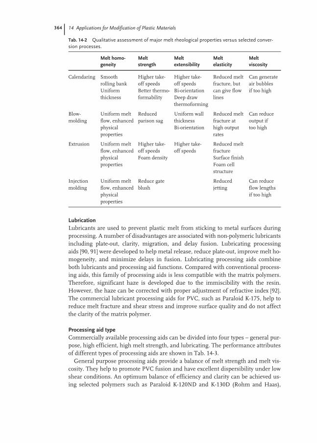
364 14 Applications for Modification of Plastic Materials
LubricationLubricants are used to prevent plastic melt from sticking to metal surfaces duringprocessing. A number of disadvantages are associated with non-polymeric lubricantsincluding plate-out, clarity, migration, and delay fusion. Lubricating processingaids [90, 91] were developed to help metal release, reduce plate-out, improve melt ho-mogeneity, and minimize delays in fusion. Lubricating processing aids combineboth lubricants and processing aid functions. Compared with conventional process-ing aids, this family of processing aids is less compatible with the matrix polymers.Therefore, significant haze is developed due to the immiscibility with the resin.However, the haze can be corrected with proper adjustment of refractive index [92].The commercial lubricant processing aids for PVC, such as Paraloid K-175, help toreduce melt fracture and shear stress and improve surface quality and do not affectthe clarity of the matrix polymer.
Processing aid typeCommercially available processing aids can be divided into four types – general pur-pose, high efficient, high melt strength, and lubricating. The performance attributesof different types of processing aids are shown in Tab. 14-3.
General purpose processing aids provide a balance of melt strength and melt vis-cosity. They help to promote PVC fusion and have excellent dispersibility under lowshear conditions. An optimum balance of efficiency and clarity can be achieved us-ing selected polymers such as Paraloid K-120ND and K-130D (Rohm and Haas),
Tab. 14-2 Qualitative assessment of major melt rheological properties versus selected conver-sion processes.
Melt homo- Melt Melt Melt Melt geneity strength extensibility elasticity viscosity
Calendaring Smooth Higher take- Higher take- Reduced melt Can generaterolling bank off speeds off speeds fracture, but air bubbles Uniform Better thermo- Bi-orientation can give flow if too highthickness formability Deep draw lines
thermoforming
Blow- Uniform melt Reduced Uniform wall Reduced melt Can reduce molding flow, enhanced parison sag thickness fracture at output if
physical Bi-orientation high output too highproperties rates
Extrusion Uniform melt Higher take- Higher take- Reduced melt flow, enhanced off speeds off speeds fracturephysical Foam density Surface finishproperties Foam cell
structure
Injection Uniform melt Reduce gate Reduced Can reduce molding flow, enhanced blush jetting flow lengths
physical if too highproperties

14.3 Processing Aids 365
Kane Ace PA-20/30 (Kanegafuchi), Metablen P501(Atofina/Mitsubishi Rayon) andBarorapid 3F(Barlocher). High efficiency processing aids produce even higher meltstrength than the general purpose type. This is attributed to their higher polymermolecular weight. In addition to higher melt strength. This type of processing aidimproves melt homogeneity and processing rate, and provides better surface qualitydimensional control in the finished product, even in a highly filled system such aspipe formulation. The most common high-efficient processing aids are Paraloid K-125 (Rohm and Haas), Metablen P550/P551 (Atofina/Mitsubishi Rayon), VestiformR315 (Huls), and Vinuran 3833 (BASF). As mentioned in the previous section, meltstrength processing aids are mainly used in PVC foam applications, including pro-file, foam core pile, and foam sheet. These processing aids provide low foam density,high surface quality, and a consistent processing. The recommended processing aidsare Paraloid K-400/K415/K-435 (Rohm and Haas), Metablen P530 (Atofina/Mit-subishi Rayon), Kane Ace PA-40 (Kanegafuchi), Baroropid 10F/20F/30F (Barlocher).Polymeric lubricants that improve melt processing, hot metal release, melt fracture,and process efficiency are defined as lubricating processing aids. The common lu-bricating processing aids include Paraloid K-175 (Rohm and Haas), Kane Ace PA-101 (Kanegafuchi), Metablen P710 (Atofina/Mitsubishi Rayon), Vestiform R450(Huls), and Vinuran 3833 (BASF).
It is very common that a PVC compound is formulated with more than one type ofprocessing aid. Historically, the combination of different types of processing aidscould provide the converters with optimum processing. The combination of a lubri-cating processing aid such as Paraloid K-175 with other types of processing aids,such as Paraloid K-120ND, K-125, or K-130D, is commonly applied to applicationssuch as blow-molded containers, calendered or extruded sheet, siding, profile extru-sion, high-flow injection-molded parts, pipe fittings, conduit, etc. The balance ofmelt rheology, melt homogeneity, and hot metal release affects the aesthetics, as well as the productivity. A proper level of each ingredient is critical and can affect the product quality. As shown in Fig. 14-6, an optimal level of Paraloid K-130D with
Tab. 14-3 Processing aid type versus performance attributes.
Processing Aid Type General High High melt Lubricatingpurpose efficiency strength
Molecular weight (Mw × 106) 1–3 3–5 6+ < 1Melt homogeneity ++++ ++++ ++++ ++Melt strength (increase) ++ +++ ++++ +Melt elasticity (increase) ++ +++ ++++ +Melt extensibility ++ +++ ++ +Melt viscosity (increase) + +++ +++ +Fusion time + ++ +++ +Dispersion (under low shear) ++++ ++ + ++++Clarity in PVC +++ +++ ++ ++++Stress whitening resist. ++++ ++++ NA ++++Hot metal release/lub. + + + ++++
+ = least, ++++ = greatest

366 14 Applications for Modification of Plastic Materials
K-175 helps to improve optical clarity as well as to eliminate flow-line and air marksin a rigid clear PVC calendered sheet.
14.3.2
Processing Aids for Other Resins
The use of processing aids to improve melt processing behaviors in resins other thanPVC has increased in the recent years. Some of the polymeric processing aids aremanufactured by emulsion polymerization but some of them are not. Acrylic pro-cessing aids were found to improve melt strength and melt homogeneity in thermo-plastics such as polyolefins, polyesters, polycarbonate, and ABS/SAN blends [63–70].Methacrylate based polymers are reported to enhance the mill-processing of polyeth-ylene. The higher alkyl methacrylates based processing aids improve the meltstrength of polypropylene and are useful in thermoforming operations to producecontainers and appliance housings. Lower molecular weight methacrylate based pro-cessing aids were applied as rheology modifiers in ABS to lower melt viscosity and tofacilitate melt processing [93]. Addition of an extremely low level of fluorocarbonprocessing aid reduces melt viscosity and eliminates melt fracture in a film extrusionof linear low density polyethylene [94]. Poly(vinylidene chloride), also known asPVDC, is used in packaging applications, especially multilayer film and sheet, due toits high strength and barrier properties. However, PVDC is significantly less stablethan PVC and would normally degrade rapidly at the temperature required for pro-cessing. Acrylic based additives reduce the thermal degradation and preserve the ma-jority of important properties [95]. Poly(vinyl alcohol), PVOH, is another thermo-plastic with excellent barrier properties but poor processability upon heat and shearstress. The use of high molecular weight polymers as processing aids for PVOH en-ables a smooth melt processing without compromising the rigidity and barrier prop-erties [71–73]. The melt strength and melt viscosity of aromatic polyesters such aspoly(ethylene terephthalate), PET, can be increased substantially by the addition of alow level of processing aid [69].
Fig. 14-6 Effect of processing aid on flow lines and air marks of calen-dered sheet. Clear and rigid PVC formulation (A) 1.5 phr Paraloid K-130Dand 0.75 phr Paraloid K-175, (B) 1.5 phr Paraloid K-130D and 0.25 phrParaloid K-175, (C) 1.5 phr Paraloid K-125 and 0.25 phr Paraloid K-175.The film thickness is approximately 0.5 mm.
(A) (B) (C)
14.4 Impact Modifiers 367
14.4
Impact Modifiers
Impact resistance, or toughness, refers to the ability of a material to withstand highrates of applied loads, and thus high energy absorption, without undergoing cata-strophic failure due to fracture. Many plastics suffer from inherent brittleness, andeven those commonly thought to have relatively high ductility, such as polycarbon-ate, may become embrittled at very cold temperatures, by physical aging or throughhigh stresses or flaws introduced into the material.
The key to improving the impact resistance of a plastic is to enable the polymer toabsorb larger amounts of mechanical energy, while at the same time avoid plasticiz-ing or softening the polymer, which can lead to large tradeoffs in other mechanicalproperties, such as tensile or flexural modulus. The most common solution to thisdilemma is the introduction of a second, softer polymer phase into the plastic. In thefinal processed material, this soft, rubbery phase ideally exists as discrete domainsdispersed within the plastic to enable the impact energy absorption, while the con-tinuous glassy phase dominates the surface hardness and other mechanical proper-ties.
In some cases, a blend containing the discrete rubber domains may be created “in-reactor” through chemical process modifications during the manufacture of thebase polymer matrix material. Often it is difficult to properly control the desiredblend morphology, and the extra process steps introduce additional complexity andcost into the process. Another limitation to the in-situ approach is that a typical man-ufactured polymer resin may be used in a wide variety of downstream applications,each with its own unique performance requirements, and therefore the desired ma-terial modifications may also vary. Improved flexibility in formulating and process-ing is provided by using an additive approach, in which the characteristics of thefinal blend are produced by formulating and adding the desired type and amount ofmodifying additives just prior to or during the final melt processing step. In the caseof impact modifiers, emulsion technology provides an ideal method for meeting therequirements for such an additive system. Emulsion polymerization methods canproduce very high molecular weight, low Tg polymers having ideal elastomeric prop-erties for impact modification. Particles of highly uniform particle size, in the rangeof tens to hundreds of nanometers, may be synthesized. Through the use of standardcrosslinking techniques, particle size is permanently set so that the original emul-sion particle is preserved during the plastic melt processing step. This ability to pro-duce and control the optimal blend morphology and final domain size of the rubberyphase is extremely important in achieving good impact resistance in the resultingplastic material.
The development of multiple-stage, or “core-shell” emulsion graft copolymers wasan important milestone in impact modifier technology [96, 97]. Using core-shelltechnology, the rubber core can be designed to optimize impact performance, whilea higher Tg outer stage eliminates the tackiness normally associated with rubberypolymers and so allows for easier isolation, storage and handling. The outer stage, orstages, can also be designed to enhance the processing and dispersion attributes of

368 14 Applications for Modification of Plastic Materials
the additive, most typically in the case where the shell polymer composition is cho-sen based on its compatibility with the matrix polymer, which promotes improvedmixing to form the optimal dispersed-phase blend morphology.
In addition to composition, the particle size and distribution of the rubbery modi-fier must be carefully controlled. It is well known that impact performance is highlydependent on particle size [98]. Small particles are thought to be effective due to thelarger total number of particles distributed in the matrix, and the resulting shorterinterparticle distances [99–101]. The thin sections or ligaments of matrix betweenthe particles are more susceptible to induced shear deformation and drawing than athicker part or section. In some matrix systems, the energy absorption mechanismmay occur via multiple crazing or cracking, in which case large particles may be fa-vored due to their ability to initiate and arrest the growth of these localized frac-tures [102]. Recent work in understanding impact mechanisms has focused on thepossible role of cavitation, or voiding, within the rubber domains during the impactevent, which allows for stress release and increased deformation of the adjacent ma-trix [103–105]. Larger particles are thought to be more conducive to this cavitationmechanism. The optimal rubber domain particle size for impact resistance is there-fore based on a balance of these competitive effects, and varies depending on the na-ture of the matrix resin system being modified [106, 107].
Impact specifications and test methods vary according to application. Most com-monly, testing is done using a notched Izod or Charpy pendulum impact test, for ex-ample, as specified by ASTM D256 or ISO 179 protocols. Specimens are prepared bycutting a small initial notch into a bar of the plastic material to be tested, and mount-ed onto a pendulum-type impact tester. The pendulum hammer falls and strikes thesample to initiate fracture at the notch. The total energy absorbed in the fracture ismeasured from the loss in potential energy of the pendulum. Impact energy is nor-malized and reported in units of energy per area or length of crack.
Another common impact test method involves the use of a dropped weight or dartto impact a flat surface or sheet of processed plastic material. The dart may be in-strumented, in which case the actual energy, load and elongation properties of thematerial may be measured as the dart punctures the material. A more basic drop testis the Gardner test, in which the drop height (and therefore potential energy) of theweight is increased until material failure is observed [108].
14.4.1
Impact Modifiers for PVC
Poly(vinyl chloride) (PVC) is the largest and most important resin for the applicationof emulsion-based impact modifiers. In 1999, over 25 million tons (50 billion lb) ofPVC were produced worldwide [109, 110]. Virtually all of the emulsion-made impactmodifiers for PVC applications are of the core-shell variety, with the largest com-mercial producers being Rohm and Haas, AtoFina, Kaneka and Mitsubishi Rayon.
PVC is a unique polymer in that, while the neat resin is virtually useless, it can bemodified by various additives to provide a tremendous range of properties, rangingfrom soft and flexible to rigid and tough. PVC is an inherently tough polymer, but is

14.4 Impact Modifiers 369
characterized as notch sensitive [111]. Notch or crack sensitivity refers to the inabili-ty of a material to resist fracture in the presence of a notch, crack, flaw or other site ofpotential high stress concentration. This feature, along with the potential for embrit-tlement at sub-ambient use temperatures, lead to most PVC applications requiringsome form impact modification. In a typical impact experiment, as shown in Figs 14-7 and 14-8, the inclusion of a moderate amount of impact modifier producesan almost tenfold increase in impact energy absorption vs. the neat resin, and large-ly negates the negative effects of lower temperatures or sharper notches in the testspecimen.
Various mechanisms have been proposed to explain the effectiveness of rubber do-mains in improving the toughness of plastic resins [106]. It is now generally accept-ed that the primary source of energy dissipation occurs in the matrix resin itself,rather than in the rubber domains [98–112]. The primary role of the rubberydomains is to provide multiple sites of highly localized stress concentrations, whichtend to occur when a load is applied at the interface of materials having differentmoduli [101]. In the case of PVC, which is intrinsically ductile, the localized stressescan exceed the yield stress of the material, and plastic flow or deformation occurs inpreference to crack initiation and/or propagation [101, 113, 114]. In this way, largeamounts of energy are absorbed through an increase in elongation of the material atmoderate load levels (Fig. 14-9).
Fig. 14-7 Influence of temperature and core-shell modifier addition on theimpact performance of PVC.
0
200
400
600
800
1000
1200
0 1 2 3 4 5 6 7
23 C.
20 C.
No
tch
ed
Izo
d I
mp
ac
t E
ne
rgy
(J
/m)
0.25 mm notch radius
Impact Modifier Level in PVC (phr)

370 14 Applications for Modification of Plastic Materials
PVC building productsRigid, unplasticized PVC is used extensively in the building and construction mar-kets. Pipe, vinyl siding, and window profiles, all manufactured via profile or sheet ex-trusion, represent the largest building product markets. Examples of some formula-tions are shown in Tab. 14-4.
Building products often require a high degree of rigidity, heat distortion resist-ance, and intrinsic toughness, attributes which are aided by the use of high molecu-lar weight PVC resins, with K values typically greater than 65. These applications aregenerally formulated to be opaque, and white or light pastel in color, so that for the
Fig. 14-8 Notch sensitivity of PVC. At smaller notch radii (sharper notch),the PVC specimen is embrittled. Core-shell impact modifiers reduce thenotch sensitivity.
0
500
1000
1500
2000
2500
0 1 2 3 4 5 6 7
0.25 mm Notch Radius
0.50 mm Notch Radius
1.30 mm Notch Radius
No
tch
ed
Izo
d I
mp
ac
t E
ne
rgy
(J
/m)
Impact Modifier Level (phr)
20 C.
Fig. 14-9 Effect of impactmodification on the macro-scopic tensile properties of apolymer such as PVC. The im-pact modifier lowers the yieldstress of the polymer, allowingthe polymer to yield and under-go extensive elongation. Theenergy absorbed is calculatedfrom the area under the stress-strain curve.
UnmodifiedImpact ModifiedPVCYield point
Load
Elongation

14.4 Impact Modifiers 371
purpose of optical properties, additives can generally be designed without considera-tion to refractive index and particle size.
The key distinguishing feature of impact modifiers used in building products isweatherability, allowing the final modified PVC parts to retain color and mechanicalproperties after extensive exposure to UV radiation. This requirement is well metthrough the use of all-acrylic polymer compositions, which contain no residual un-saturated sites susceptible to UV degradation [115, 116]. Acrylic impact modifiershave a rubbery core based on low Tg acrylates with moderately long side chains.Poly(butyl acrylate), with a Tg of approximately –45 °C, is most commonly used com-mercially, providing good elastomeric properties at reasonable cost. The rubberycore, which typically makes up 70 to 90 % of the total modifier, is crosslinkedthrough the addition of small amounts of multifunctional monomers during the freeradical acrylate polymerization, so that the resulting crosslinked core contains lessthan 5 % extractable polymer. There are also examples of acrylic modifiers contain-ing small amounts of non-weatherable, but very low Tg monomers, such as butadi-ene, which may enhance the rubbery features of the core at the expense of smalltradeoffs in weatherability [117, 118]. Optimal impact performance for all-acrylicmodifiers in PVC building products is attained through the use of particles with di-ameters in the 80–300 nm range.
A hard stage or shell is polymerized around the rubber core to allow for isolation ofthe emulsions into non-compacting, free flowing powders, as well as to provide vari-ous performance properties. The shell plays a critical role in impact modification byenabling easier mixing and dispersion of the modifier into the polymer matrix. Inweatherable PVC applications, this is usually achieved through the use of apoly(methyl methacrylate) based shell composition, which combines a suitably highTg with excellent miscibility in PVC [119–121]. The shell polymer, unlike the rubberycore, is generally not highly crosslinked, so that the shell polymer chains are free tomix and interact with the surrounding matrix on the molecular level. A modifierwith insufficient amounts of PVC-compatible materials in the shell will result inpoorer dispersion of the modifier (Fig. 14-10), leading to poorer impact (Fig. 14-11).
Tab. 14-4 Examples of PVC formulations for building products (parts per hundred resin).
Siding capstock Window profile Pipe
PVC, K-67 100.0 100.0 100.0Tin stabilizer 1.2 1.2 0.4Calcium stearate 1.2 1.5 0.8Paraffin wax 165 °F 1.0 – 1.2Polyethylene wax 0.1 – –Bisamide wax – 1.7 –Oxidized polyethylene wax – 0.1 0.15Titanium dioxide 8.0 9.0 8.0Calcium carbonate 5.0 3.0 5.0Process aid (K-120 type) 1.0 1.0 0.5Lubricating proc. aid 0.5 – –Acrylic impact modifier 5.0 4.0 3.0

372 14 Applications for Modification of Plastic Materials
The shell can further be designed around desired rheological and secondary prop-erties. Shell molecular weight, degree of grafting, and composition can alter process-ing and rheology properties such as viscosity, melt strength, die swell and PVC fu-
Fig. 14-11 Impact performance of the two modifiers compared in Fig. 14-10. Better compatibility and dispersion of the modifier in the PVCresults in superior impact efficiency.
0
240
480
720
960
1200
14 16 18 20 22 24
Modifier A (poor dispersion)
Modifier B (good dispersion)
No
tch
ed
Izo
d I
mp
ac
t E
ne
rgy
(J
/m)
Impact Test Temperature (C.)
10 % Modifier
Fig. 14-10 Modifier shell effects on dispersionin PVC. The all-acrylic modifier particles are thesmall white particles in the micrographs, whilethe larger white and black particles are voidsand inorganic fillers. Modifier A, containing a
shell with poor PVC miscibility, produces largeagglomerates and there are significant areas ofunmodified matrix. Modifier B has a more mis-cible shell, resulting in more uniform disper-sion in the PVC resin.
1.0 mm 1.0 mµ
x 50.000 x 50, 000
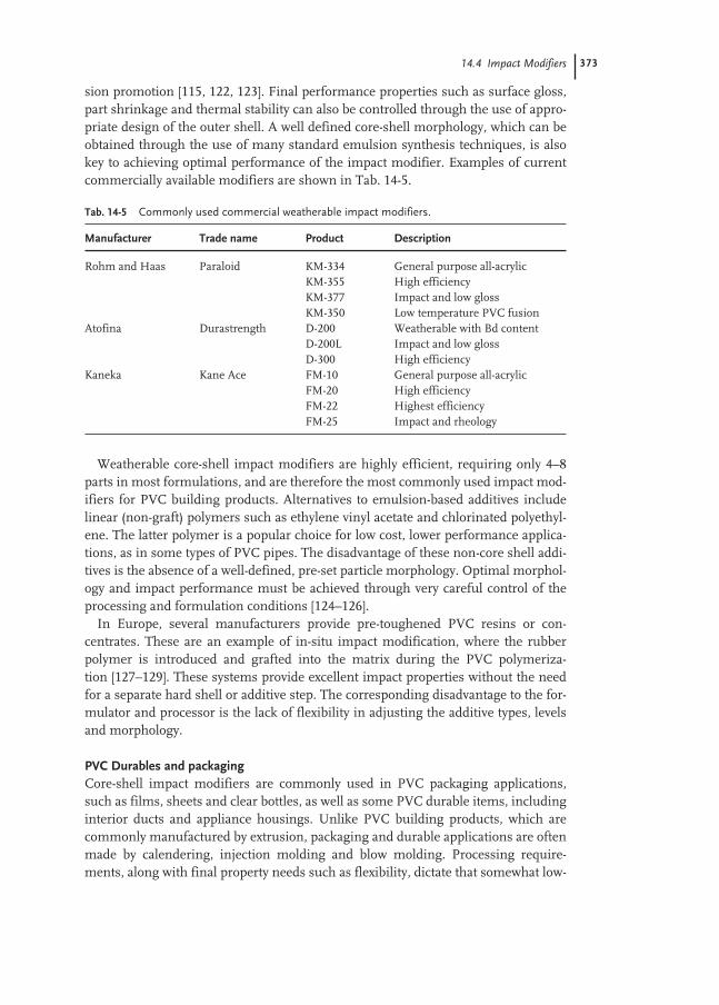
14.4 Impact Modifiers 373
sion promotion [115, 122, 123]. Final performance properties such as surface gloss,part shrinkage and thermal stability can also be controlled through the use of appro-priate design of the outer shell. A well defined core-shell morphology, which can beobtained through the use of many standard emulsion synthesis techniques, is alsokey to achieving optimal performance of the impact modifier. Examples of currentcommercially available modifiers are shown in Tab. 14-5.
Weatherable core-shell impact modifiers are highly efficient, requiring only 4–8parts in most formulations, and are therefore the most commonly used impact mod-ifiers for PVC building products. Alternatives to emulsion-based additives includelinear (non-graft) polymers such as ethylene vinyl acetate and chlorinated polyethyl-ene. The latter polymer is a popular choice for low cost, lower performance applica-tions, as in some types of PVC pipes. The disadvantage of these non-core shell addi-tives is the absence of a well-defined, pre-set particle morphology. Optimal morphol-ogy and impact performance must be achieved through very careful control of theprocessing and formulation conditions [124–126].
In Europe, several manufacturers provide pre-toughened PVC resins or con-centrates. These are an example of in-situ impact modification, where the rubber polymer is introduced and grafted into the matrix during the PVC polymeriza-tion [127–129]. These systems provide excellent impact properties without the needfor a separate hard shell or additive step. The corresponding disadvantage to the for-mulator and processor is the lack of flexibility in adjusting the additive types, levelsand morphology.
PVC Durables and packagingCore-shell impact modifiers are commonly used in PVC packaging applications,such as films, sheets and clear bottles, as well as some PVC durable items, includinginterior ducts and appliance housings. Unlike PVC building products, which arecommonly manufactured by extrusion, packaging and durable applications are oftenmade by calendering, injection molding and blow molding. Processing require-ments, along with final property needs such as flexibility, dictate that somewhat low-
Tab. 14-5 Commonly used commercial weatherable impact modifiers.
Manufacturer Trade name Product Description
Rohm and Haas Paraloid KM-334 General purpose all-acrylicKM-355 High efficiencyKM-377 Impact and low glossKM-350 Low temperature PVC fusion
Atofina Durastrength D-200 Weatherable with Bd contentD-200L Impact and low glossD-300 High efficiency
Kaneka Kane Ace FM-10 General purpose all-acrylicFM-20 High efficiencyFM-22 Highest efficiencyFM-25 Impact and rheology

374 14 Applications for Modification of Plastic Materials
er molecular weight PVC resins are used, typically in the K-50 to K-65 range. Sincelower molecular weight resins have intrinsically lower toughness, it is often neces-sary to add higher levels of impact modifier. Examples of some formulations areshown in Tab. 14-6. Note that, in addition to the impact modifier, the combinationsof lubricants in these formulations differ from those associated with building prod-ucts.
Because weatherability is often not an important requirement, core-shell modi-fiers in this area are usually based on butadiene rubbers. Polybutadiene is economi-cal, has an extremely low Tg of approximately –80 °C, and superior elastomeric prop-erties, leading to higher potential impact performance than all-acrylic compositions.Core-shell modifiers based on a butadiene homopolymer core result in the highestimpact efficiency, but are useful only in opaque applications. Many packaging appli-cations require high transparency, which can be achieved through refractive indexmatching of the modifier composition with the PVC matrix [130]. Appropriateamounts of styrene can be incorporated into the core and shell of the modifier toadjust the modifier refractive index, at the expense of some embrittlement of the p-Bd rubber and resulting lower impact efficiency. Crosslinking of the Bd or Bd/Stycore is controlled through process-induced self-crosslinking of Bd, and also throughthe use of added multifunctional cross-linkers, such as divinylbenzene.
The role of the shell is analogous to the case of all-acrylic modifiers, although themolecular structure and composition must be tailored for different processing re-quirements and secondary properties. Methyl methacrylate and styrene-acrylonitrileare common compositions that provide good processing and miscibility with thePVC. In transparent applications, complete breakdown of the modifier powder parti-cles and complete dispersion back to the emulsion particle size scale are necessary toavoid haze and optical inhomogeneities cause by gels. Stress whitening is also a
Tab. 14-6 Examples of non-weatherable PVC formulations (parts per hundred resin).
PVC electrical box Bottle Clear film
PVC, K-57-58 100.0 100.0 100.0Tin stabilizer 2.0 1.5 1.2Calcium stearate 1.0 – –Paraffin wax 165 °F – – 0.6Glycerol monostearate – 0.5 0.6Montan ester wax – 0.2 0.2Saturated ester wax – – 0.1Titanium dioxide 1.5 – –Calcium carbonate 5.0 – –Process aid 0.4 1.0 1.0Lubricating proc. aid 1.2 – 1.0Bd-based impact modifier – – 20.0MBS clear impact modifier – 12.0 10.0Heat distortion additive 30.0 – –Blue toner – – 0.06

14.4 Impact Modifiers 375
common occurrence in transparent films, and can be minimized by proper design ofthe modifier for adhesion and void resistance [131]. Antioxidants and heat stabilizersare often added to Bd-based modifiers to prevent undue degradation of the modifiersduring the high temperature drying and melt processing operations. In food packag-ing applications, impact modifiers must also meet specific FDA toxicity andorganoleptic requirements.
Some examples of commercially available Bd-based impact modifiers, and associ-ated applications, are shown in Tab. 14-7.
14.4.2
Engineering Resins
Engineering resins offer superior performance in various mechanical, thermal andaesthetic properties, and encompass a wide variety of compositions and applications.These polymers range from those that are considered inherently tough, such as poly-carbonate, nylon, and polyethylene terephthalate, to the more brittle polystyrene andSAN [106]. Although the toughening mechanisms, morphologies and optimal parti-cle size for impact modification are specific to each type of matrix, the generalapproach of adding a second phase of rubbery material is common to most cases. Incontrast to PVC, a much broader range of rubber technologies, both emulsion andnon-emulsion based, is used commercially. The higher processing temperatures ofengineering resins require the addition of significant levels of heat stabilizers andantioxidants to acrylic or butadiene based emulsion rubbers [132, 133]. Resins otherthan PVC are usually compounded as pellets, rather than powders, which lessens the advantages in powder properties provided by emulsion polymer isolation tech-niques.
The most widely used emulsion based additives are the all-acrylic or MBS core-shell polymers. Methacrylate-based shell compositions are generally not highly mis-cible with the various engineering resin compositions, creating a challenge for prop-er impact modifier dispersion and adhesion. Common approaches to this problem
Tab. 14-7 Commonly used commercial non-weatherable impact modifiers.
Manufacturer Trade name Product Description
Rohm and Haas Paraloid BTA-730 Clear film and sheetBTA-833 Clear bottlesBTA-715 Low crease whiteningBTA-753 High efficiency, opaqueBTA-751 High efficiency, opaque, injection molding
Atofina/Mitsubishi, Metablen C-201 Clear film and sheet, bottlesRayon C-132 Low Crease whitening
C-223 High efficiency opaqueKaneka Kane Ace B-52 High efficiency opaque
B-51 Low crease whiteningB-22 Clear film and sheet, bottles
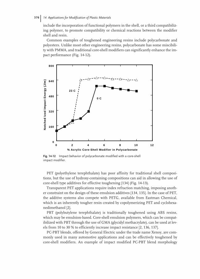
376 14 Applications for Modification of Plastic Materials
include the incorporation of functional polymers in the shell, or a third compatibiliz-ing polymer, to promote compatibility or chemical reactions between the modifiershell and resin.
Common examples of toughened engineering resins include polycarbonate andpolyesters. Unlike most other engineering resins, polycarbonate has some miscibili-ty with PMMA, and traditional core-shell modifiers can significantly enhance the im-pact performance (Fig. 14-12).
PET (polyethylene terephthalate) has poor affinity for traditional shell composi-tions, but the use of hydroxy-containing compositions can aid in allowing the use ofcore-shell type additives for effective toughening [134] (Fig. 14-13).
Transparent PET applications require index refraction matching, imposing anoth-er constraint on the design of these emulsion additives [134, 135]. In the case of PET,the additive systems also compete with PETG, available from Eastman Chemical,which is an inherently tougher resin created by copolymerizing PET and cyclohexa-nedimethanol [2].
PBT (polybutylene terephthalate) is traditionally toughened using ABS resins,which may be emulsion-based. Core-shell emulsion polymers, which can be compat-ibilized with PBT through the use of GMA (glycidyl methacrylate), can be used at lev-els from 10 to 30 % to efficiently increase impact resistance [2, 136, 137].
PC-PBT blends, offered by General Electric under the trade name Xenoy, are com-monly used in many automotive applications and can be effectively toughened bycore-shell modifiers. An example of impact modified PC-PBT blend morphology
Fig. 14-12 Impact behavior of polycarbonate modified with a core-shellimpact modifier.
0
160
320
480
640
800
0 2 4 6 8 10 12
No
tch
ed
Izo
d I
mp
ac
t E
ne
rgy
(J
/m)
% Acrylic Core-Shell Modifier in Polycarbonate
23 C
0 C
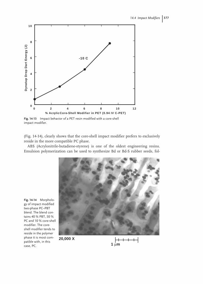
14.4 Impact Modifiers 377
(Fig. 14-14), clearly shows that the core-shell impact modifier prefers to exclusivelyreside in the more compatible PC phase.
ABS (Acrylonitrile-butadiene-styrene) is one of the oldest engineering resins.Emulsion polymerization can be used to synthesize Bd or Bd-S rubber seeds, fol-
Fig. 14-13 Impact behavior of a PET resin modified with a core-shell impact modifier.
0
2
4
6
8
10
0 2 4 6 8 10 12
Dy
na
tup
Dro
p D
art
En
erg
y (
J)
% Acrylic Core-Shell Modifier in PET (0.94 IV C-PET)
-10 C
Fig. 14-14 Morpholo-gy of impact modifiedtwo-phase PC–PBTblend. The blend con-tains 40 % PBT, 50 %PC and 10 % core-shellmodifier. The core-shell modifier tends toreside in the polymerphase it is most com-patible with, in thiscase, PC.
20,000 X
1 µm

378 14 Applications for Modification of Plastic Materials
lowed by additional polymerization of styrene and acrylonitrile to form an in-situimpact modified resin. Alternatively, the composition can be blended with addition-al SAN polymer to produce the desired blend ratios and properties [138]. Core-shellpolymers can be created by minimizing and carefully controlling the SAN polymer-ization to create the desired morphology. These ABS polymers can be used as addi-tives to modify SAN and other resin matrices.
Impact modification of nylons is generally achieved through the incorporation ofreactive groups in the rubber [139, 140]. Since these compositions react with the ny-lon during the melt processing, the conditions and compositions must be carefullycontrolled to prevent undesired increases in melt viscosity. While core-shell modi-fiers have been applied successfully to these systems [141, 142], the most commoncommercial approach is the use of olefin-based elastomers grafted with functionalmonomers as maleic anhydride.
PMMA, commonly known as Plexiglas®, provides an interesting example of theapplication of emulsion synthesis to design multi-layer core-shell impact modi-fiers [143, 144]. A common three-stage polymer used to impact modify commercialPMMA resins contains a hard, methacrylate based inner core, surrounded by aninner, soft acrylate shell, and further encapsulated by a PMMA based outer stage.The role of the inner hard core is to provide refractive index matching and improvedstiffness retention to the overall matrix. Additional studies have demonstrated theeffectiveness of a large number of alternative multilayer designs in improving thetoughness and balance of properties in impact modified PMMA [145].
AcknowledgmentThe authors wish to thank the Rohm and Haas Company for their support.

379
References
1 S. K. Porwal, Modern Plastics Encyclope-dia ’99, 1999, A23–A27.
2 C. A. Cruz-Ramos, Core-Shell ImpactModifiers, in: Polymer Blends, Volume 2:Performance, D. R. Paul, C. B. Bucknall(eds), Wiley, 2000.
3 J. M Brady, C. A. Cruz-Ramos, Process-ing Aids, in: Polymer Blends, Volume 2:Performance, D. R. Paul, C. B. Bucknall(eds), Wiley, 2000.
4 J. T. Lutz, Jr, D. L. Dunkelberger, ImpactModifiers for PVC, The History and Prac-tice, J. Wiley and Sons, NY, 1992.
5 D. L. Dunkelberger, Processing Aids forPVC, in: Plastics Additives and ModifiersHandbook, J. Edenbaum (ed.), Van Nos-trand Reinhold, NY, 1992, Chapter 60.
6 Y. Nakamura, H. Tabata, H. Suzuki, K. Ito, M. Okubo, T. Matsumoto, J. Appl.Poly. Sci. 1986, 32, 4865.
7 D. E. Henton, D. M. Pickelman, C. B.Arends, V. E. Meyer, US Pat. 4,778,851(1988).
8 J. Wiersma, J. Meyer, D. Leblanc, R. Berardino, Toughening of Epoxyresins Using Core-Shell Modifiers, in: Fourth International Conference Addi-tives ’96, S. M. Andrews, C. A. Cruz, A. Golovoy, C. A. Wilkie (eds), ExecutiveConference Management, Houston,1996.
9 J. Y. Qian, R. A. Pearson, V. L. Dimonie,M. S. El-Aasser, J. Appl. Polym. Sci. 1995,58, 439.
10 G. L. Shaffer, R. Bagheri, J. Y. Qian, V.Dimonie, R. A. Pearson, M. S. El-Aasser,J. Appl. Polym. Sci. 1995, 58, 465.
11 R. H. Backderf, C. D. Guiley, Jr, US Pat.4.082,895, 1978.
12 R. G. Gilbert, Emulsion Polymerization: A Mechanistic Approach, Academic Press,1995.
13 P. A. Lovell, M. S. El-Asser (eds) Emul-sion Polymerization and Emulsion Poly-mers, Wiley and Sons, Chichester, UK,1997.
14 D. C. Blackley, Polymer Lattices, Scienceand Technology, 2nd edn, Chapman andHall, London, 1997.
15 US Pat. 4,179,481 (December 18, 1977),M. Tuzuki, K. Matuba (to Kanegafuchi).
16 US Pat. 4,699,948 (November 25,1985), K. Kishida, K. Ueda, M. Kaneda(to Mitsubishi Rayon KK).
17 US Pat. 4,668,740 (May 26, 1987), K. Okano (to Mitsubishi).
18 US Pat. 3,883.686 (September 3, 1984)R. J. Grochowski, R.K. Graham, J. Whang (to Rohm and Haas).
19 Eur. Pat. 208585A1 (Jan. 14, 1987) J. M. Paul, C. L. Cretenot, A.Vigouroux (to Norsolor S.A.).
20 US Pat. 4,206,292-A (June 3, 1980) Y. Iizuka, S. Midorikawa, M. Oya (to Kureha).
21 Japanese Pat. 62086042-A (Apr. 20,1987) Nagasawa, T. Okamoto, K. Shudo (to Chisso Corp.).
22 US Pat. 3,027,347 (March 27, 1962) H. Fikenstscer, K. Heerle (to BASF).
23 Eur. Pat. 484,723 (May, 13, 1992), H. Goertz, G. Hatzman, W. Oschmann(to BASF).
24 Eur. Pat. 484,723 (May, 13, 1992), H. Goertz, G. Hatzman, W. Oschmann(to BASF).
25 US Pat. 4,584,349 (April 22, 1987), M. H. Lehr (to BF Goodrich).
26 US Pat. 4,699,948 (Oct. 13, 1987), K. Kishida, K. Ueda, M. Kaneda (to Mitsubishi).
27 US Pat. 4,730,024 (March 8, 1988), K. Kishida, K. Ueda, M. Kaneda (to Mitsubishi).
28 J. Zelinger, E. Volfova, V. Altmann, M. Tomka, Sb. Vys. Sk. Chem. Technol.Praze 1981, 5, 139.
29 A. P. Wilson, V. V. Raimondi, Polym.Eng. Sci. 1987, 18, 887.
30 V.V. Raimondi, Plast. Compd. 1980, 3,77.
31 US Pat. 4,547,428 (October 15, 1985),V. Bekker, W. J. Buchleim, W. Vander-linde, D. S. T. Wang (to Monsanto).
32 Ger. Pat. 3,131,609 (February 17,1983), K. Flatau (to Chemische WerkeHuels AG).
33 Japanese Pat. 74 72341 (July 15, 1974)F. Ide, M. Asao, K. Kishida, A. Hasa-gawa (to Mitsubishi).
34 R. D. Deanin, J. D. Mast, J. Vinyl Tech1987, 9, 15.

380 References
35 Japanese Pat. 51026953 (August 29,1984) F. Ide (to Mitsubishi).
36 Japanese Pat. 06,087,997A (Mar 29 1994)(to Mitsubishi).
37 Eur. Pat. 189,872 (August 6, 1986), M. H. Lehr (to BF Goodrich).
38 US Pat. 3,975,315 (August 17, 1976), C. Parks (to BF Goodrich).
39 US Pat. 2,646,417 (July 21, 1953), G. Jennings (to BF Goodrich).
40 US Pat. 4,668,741 (May 26, 1987), L. J. Memering (to National Distillersand Chemical Corp.).
41 H. G. Elias, F. Vohwinkel, New Commer-cial Polymers, Gordon and Breach, NewYork, 1986, pp. 58–65.
42 Japanese Pat. 62015249 (January 23,1987), M. Kinoshita, H. Eguchi, S. Maeda (to Dainippon Ink Chem KK).
43 US Pat. 3,928,500 (December 13, 1975),P. Kraft, A.F. Kopacki, R. Brunner (toStauffer).
44 Eur. Pat. 195,942 (January 1, 1986), T. Thunig, R. W. Terwonne (to Huls).
45 US Pat. 3,686,363 (August 22, 1972), A. J. Yu, P. Kraft (to Stauffer).
46 Japanese Pat. 5411949 (June 30,1977), K. Tsuda, H. Eguchi, H. Tanaka (to Dainipon Ink).
47 US Pat. 4,105,624 (August 8, 1978), K. Boehlke, P. Foerster, H. G. Matthies,H. J. Sterzel (to BASF).
48 US Pat. 4,398,019 (May 19, 1982), M. K. Cox, B. P. Griffin (to ICI).
49 US Pat. 4,137,280 (January 30,1979), D. D. Dixon, M. E. Ford (to Air Products).
50 Eur. Pat. 52460A1 (May 26, 1982), P. A.Holmes, A. B. Newton, F. M. Willmouth(to ICI).
51 US Pat. 5,206,296 (Apr. 27, 1993), J. Dominique, M. Loidl (to GE).
52 Eur. Pat 99,938,955 (Aug. 24, 1999), N. Sakashita, Y. Miki, A. Takaki (toKanegafuchi).
53 Eur. Pat. 921,138 (1999), Y, Nakanishi,M. Kadokura, K. Janssen, A. Takaki, M. Miki (to Kanegafuchi).
54 US Pat. 3,859,389 (January 7, 1975), D.T. Carty, J. A. Oline (to Rohm and Haas).
55 Japanese Pat. 55160045 (December 12,1980), H. Hosoi, K. Matsuba (to Kanega-fuchi).
56 US Pat. 4,746,705 (May 24, 1988), A. Courtis, M. B. Elser (to ICI).
57 Eur. Pat. 204,974 (December 17, 1986),K. Kishida, K. Ueda, M. Kaneda (toMitsubishi).
58 US Pat. 5,371,149 (December 6, 1994),K. Kishida, K. Ueda, M. Kaneda (toMitsubishi).
59 Japanese Pat. 07,278,237 (1995), Y. Matsumoto, A. Nakada, S. Wakaba-yashi, M. Kaneda, H. Ito, K. Okano (to Mitsubishi).
60 US Pat. 4,120,833 (Oct. 17, 1978), M. Purvis, P. Grant (to Rohm andHaas).
61 US Pat. 5,789,453 (August 4, 1998), R. E. Detterman (to BF Goodrich).
62 WO. Pat. 9,943,741 (1999) N. Migita, A. Nakata, S. Wakabayashi, S. Takei (toMitsubishi).
63 Eur. Pat. 216207A (April 1, 1987), S. Matsumoto, K. Nishimoto, I. Mishi-ma, F. Nagoshi (to Kanegafuchi).
64 Eur. Pat. 230,030 (July 29, 1987), T. Maeda (to Denki Kagaku).
65 US Pat. 4,156,703 (May 29,1979), W. H. Harp (to Rohm and Haas).
66 US Pat. 4,094,927 (June,13,1978), W. H. Harp, D. Witiak, R. LaBar (to Rohm and Haas).
67 US Pat. 5,102,952 (Apr. 7,1992), N. A. Memon (to Rohm and Haas).
68 US Pat. 5,302,429 (Apr. 12,1994), N. A. Memon (to Rohm and Haas).
69 US Pat. 5,310,799 (May 10,1994), W. Carson, C. H. Lai, N. A. Memon (to Rohm and Haas).
70 US Pat. 5,506,307 (Apr. 9, 1996), N. A. Memon (to Rohm and Haas).
71 US Pat. 5,362,803 (1994), E. E. LaFleur,R. M. Amici, W. J. Work, (to Rohm andHaas).
72 US Pat. 5,378,759 (1995), R. M. Amici,E. E. LaFleur, W. J. Work, (to Rohmand Haas).
73 US Pat. 5,605,960 (1997), J. M. Brady,T. C. C. Diaz, (to Rohm and Haas).
74 K. Masters, Spray Drying Handbook,5th edn, Longman Scientific and Tech-nical, New York, 1991.
75 US Pat. 4,463,131 (1984), R. J. Grand-zol, A. J. McFaull, H. Wanger, I. S. Ra-binovic, (to Rohm and Haas).

References 381
76 H. Morikawa, S. Kato, H. Yasui, M. Hasegawa, T. Shimizu, Innovation ofMBS Powder, in: SPE Annual TechnicalConference, 1987, p.669.
77 H. Yasui, K. Higashitani, J. Colloid Inter-face Sci. 1988, 125, 472.
78 US Pat. 4,892,910 (January 9, 1990), W. Kleese, H. Rauch, P. J. Aradt, N. Suetterlia (to GmbH Rohm).
79 H-Y. Parker, J. L. Allison, ProcessingAids, in: Encyclopedia of Polymer Scienceand Technology, Index, H. F. Mark, N. M.Bikales, C. G. Overberger, G. Menges(eds), John Wiley and Sons, New York,1990, p. 307.
80 D. R. Paul, S. Newman, Polymer Blends,Vol. 1, Academic, New York, 1978.
81 U. K. Saroop, K. K. Sharama, K. K. Jain,J. Appl. Polym. Sci. 1989, 38, 1410–1437.
82 Y. Miki, Y. Nakanishi, A. Takaki, Y. Yamazaki, SPE ANTEC Proc., 1999.
83 P. Choi, M. Lynch, A. Rudin, J. The, J. Batiste, J. Vinyl Tech. 1992, 14(3), 156.
84 Y. Nakanishi, J. Silberman, R. Nishi-mura, SPE Vinyltec, Toronto, 1999.
85 J. R. Patterson, SPE ANTEC Proc., 1997,Toronto.
86 M. Hou, J. Shen, C. Chen, Chengdu KejiDaxue Xuebao, 1985, 3, 1.
87 F. Ide, K. Okano, Pure, Appl. Chem. 1981,53, 489.
88 J. Zellinger, E. Vilfva, H. Zahradnikova,Int. J. Polym. Mater. 1976, 5, 99.
89 J. Stevenson, R. Einhorn, J. Vinyl Tech.1993, 15(4), 244.
90 R. K. Graham, Preprints of ACS OrganicCoatings and Plastics, 1974, 34, 172.
91 F. Ide, Kobunshi, 1972, 49, 74.92 C. F. Ryan, Resin Review, 1969, 19, 15.93 Eur. Pat. 216207A (April 1, 1987),
S. Matsumoto, K. Nishimoto, I. Mishi-ma, F. Nagoshi (to Kanegafuchi).
94 Rudin, A. Worm, J. E. Blaklock, J. Plast.Film Sheeting 1985, 1, 189.
95 M. C. Patterson, D.L. Dunkelberger, J. Vinyl Technol. 1994, 16, 46.
96 US Pat. 3,448,173 (1969) to Rohm andHaas.
97 US Pat. 3,251,904 (1966) to Rohm andHaas.
98 A. J. Kinlock , R.J. Young, Fracture Behavior of Polymers, Elsevier, Essex, UK,1983.
99 S. Y. Hobbs, Polym. Eng. Sci. 1986, 26,74.
100 S. Wu, A. Margolina, Polymer 1990, 31,972.
101 C. B. Bucknall, Toughened Plastics, Applied Science, London, 1977.
102 A. M. Donald, E.J. Kramer, J. Appl.Polym. Sci. 1982, 27, 3729.
103 A. F. Yee, R. A. Pearson, J. Mater. Sci.1986, 21, 2462.
104 R. A. Pearson , A. F. Yee, J. Mater. Sci.1986, 21, 2475.
105 C. B. Bucknall, P. S. Heather, A. J.Lazzeri, J. Mater. Sci. 1989, 16, 2255.
106 I. Walker, A. A. Collyer, RubberToughening Mechanisms in PolymericMaterials, in: Rubber Toughened Engi-neering Plastics, A.A. Collyer (ed.),Chapman and Hall, London, 1994.
107 S. Wu, Polym. Eng. Sci. 1990, 30, 753.108 ASTM Test Methods D-3029 and ASTM
Test Method D-4226, American Societyfor the Testing of Materials, Philadel-phia, USA.
109 Modern Plastics International, Feb.2000, Chemical Week Associates, NY,p 74.
110 R. Roman, Modern Plastics Encyclopedia’99, McGraw–Hill, NY, p. B-11.
111 P. I. Vincent, Impact Test and ServicePerformance of Thermoplastics, Plasticsand Rubber Institute, London, 1971.
112 C. B. Bucknall, Adv. Polym. Sci. 1978,27,121.
113 S. Newman, S. Strella, J. Appl. Polym.Sci. 1965, 9, 2297.
114 H. Breuer, F. Haaf, J. Stabenow, J. Macromol. Sci. 1977, B14(3), 387.
115 US Pat. 3,678,133 (1972) to Rohm andHaas.
116 US Pat. 3,843,753 (1974) to Rohm andHaas.
117 US Pat. 4,542,185 (1985) to M&TChemicals.
118 US Pat. 4,567,234 (1986) to M&TChemicals.
119 D. J. Walsh, G. L. Cheng, Polymer 1984,25(4), 499.
120 L. M. Robeson, J. Vinyl Technol. 1990,12(2) 89.
121 S. Fitzwater, ACS Conference, PolymerChemistry Division, San Francisco, CA,USA, 5–10 Apr. 1992 , PolymerPreprints 1992, 33(1), 712.

382 References
122 US Pat. 6,031,047 (2000) to Rohm andHaas.
123 US Pat. 4,670,509 (1987) to Kaneka.124 A. Siegmann, A. Hiltner, Polym. Eng.
Sci. 1984, 24(11), 869.125 M. T. Berard, S. M. Williams, J. Vinyl
Add. Tech. 1996, 2(2), 117.126 A. J. Whittle, R. P. Burford, Plast. Rubber
Composites, Proc. and Appl. 1998, 27(9),395.
127 US Pat. 4,536,548 (1985) to Huls.128 US Pat. 4,798,869 (1989) to Huls.129 US Pat. 5,232,991 (1993) to Huls.130 US Pat. 3,971,835 (1976) to Rohm and
Haas.131 S. Ohtsuka, H. Watanabe, Y. Amagi, Soc.
Plast. Eng. Ann. Tech. Conf., May 1967.132 US Pat. 5,164,434 (1992) to Rohm and
Haas.133 P. R. Paolino, in: Antioxidants in Thermo-
plastic Polymer Additives, Theory and Prac-tice, J. T. Lutz (ed.) Marcel Dekker, NY,1989.
134 US Pat. 5,409,967 (1995) to Rohm andHaas.
135 J. P. Meyer, D. LeBlanc, K. Nees-Brand,Kunststoffe 1995, 85, 452.
136 S. Y. Hobbs, M. E. J. Dekkers, V. H.Watkins, J. Mater. Sci. 1988, 23,1219.
137 S. Y. Hobbs, M. E. J. Dekkers, V. H.Watkins, J. Mater. Sci. 1988, 23,1225.
138 H. Keskkula, D. Paul, in: TougheningAgents for Engineering Polymers in Rubber Toughened Engineering Plastics, A. A. Collyer (ed.),Chapman and Hall,London, 1994.
139 US Pat. 4,174,358 (1979) to DuPont.140 R. J. M. Borggreve, R. J. Gaymans,
J. Schuijer, Polymer (1989), 30, 71.141 US Pat. 4,086,300 (1977) to Rohm and
Haas.
142 R. J. Gaymans in: ToughenedPolyamides, in Rubber Toughened Engi-neering Plastics, A. A. Collyer (ed.),Chapman and Hall, London, 1994.
143 N. Shah, J. Mater. Sci. 1988, 23, 3623.144 US Pat. 3,793,402 (1974) to Rohm and
Haas.145 P. A. Lovell, J. McDonald, D. E. J.
Saunders, M. N. Sherratt, R. J. Young,Multiphase Toughening Particle Technol-ogy in Toughened Plastics I, Science andEngineering, C. K. Riew, A. J. Kinloch(eds) Advances in Chemistry Series233, American Chemical Society,Washington, DC, 1993.
146 US Pat. 4,963,622 (October 16, 1990),W. Hertz (to Union Carbide).
147 M. Kobayashi, K. Yoshihara, N. Naka,Japanese Pat. 60/166337 (1985); Chem.Abstr. 1986, 104, 89796a.
148 J. Kushida, S. Tago, T. Aoyanage,Japanese Pat. 62/39650 (1987); Chem.Abstr. 1987, 107, 1165136b.
149 J. Kushida, N. Yamada, S. Hagiwara,Japanese Pat. 62/596655 (1987); Chem.Abstr. 1987, 107, 24324n.
150 US Pat. 3,427,275 (Feb. 11, 1969), B. J. Davis, W. J. Ranson (to Reich-hold).
151 US Pat. 5,324,461 (June 28, 1994) M. Grohman (to GE).
152 US Pat. 5,278,198 (Jan. 11, 1994) M. Grohman (to GE).
153 US Pat. 5,391,585 (Feb. 21, 1995) M. Grohman (to GE).
154 US Pat. 5,237,004 (Aug. 17, 1993) J.-C. Wu (to Rohm and Haas).
155 US Pat. 5,846,657 (Dec. 8, 1998) J.-C. Wu (to Rohm and Haas).
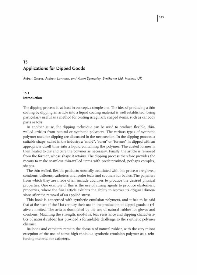
383
15
Applications for Dipped Goods
Robert Groves, Andrew Lanham, and Karen Spenceley, Synthoner Ltd, Harlow, UK
15.1
Introduction
The dipping process is, at least in concept, a simple one. The idea of producing a thincoating by dipping an article into a liquid coating material is well established, beingparticularly useful as a method for coating irregularly shaped items, such as car bodyparts or toys.
In another guise, the dipping technique can be used to produce flexible, thin-walled articles from natural or synthetic polymers. The various types of syntheticpolymer used for dipping are discussed in the next section. In the dipping process, asuitable shape, called in the industry a “mold”, “form” or “former”, is dipped with anappropriate dwell time into a liquid containing the polymer. The coated former isthen heated to dry and cure the polymer as necessary. Finally, the article is removedfrom the former, whose shape it retains. The dipping process therefore provides themeans to make seamless thin-walled items with predetermined, perhaps complex,shapes.
The thin walled, flexible products normally associated with this process are gloves,condoms, balloons, catheters and feeder teats and soothers for babies. The polymersfrom which they are made often include additives to produce the desired physicalproperties. One example of this is the use of curing agents to produce elastomericproperties, where the final article exhibits the ability to recover its original dimen-sions after the removal of an applied stress.
This book is concerned with synthetic emulsion polymers, and it has to be saidthat at the start of the 21st century their use in the production of dipped goods is rel-atively limited. The area is dominated by the use of natural rubber for gloves andcondoms. Matching the strength, modulus, tear resistance and dipping characteris-tics of natural rubber has provided a formidable challenge to the synthetic polymerchemist.
Balloons and catheters remain the domain of natural rubber, with the very minorexception of the use of some high modulus synthetic emulsion polymer as a rein-forcing material for catheters.

384 15 Applications for Dipped Goods
For condoms, no synthetic aqueous emulsion polymer is used. Currently, the al-ternative to natural rubber is provided by polyurethane dipped from organic solvent.
It is in the area of hand protection that synthetic emulsion polymers have made in-roads into the dominance of natural rubber. Accurate market figures are difficult toobtain, but it is believed that currently some 12 % of the estimated 400 000 dry tonneworldwide market for polymeric gloves (excluding household gloves) is with synthet-ic emulsion polymers, while about 15 % uses non-aqueous synthetic products.
The protective glove market can be subdivided as follows.
DisposableMedical Surgical (approx. 12 g per piece)
Examination (approx. 8 g per piece)Light industrial (approx. 8 g per piece)
UnsupportedHousehold (approx. 30 g per piece)Industrial (20 to 100 g per piece)Fabric-supported (Fabric glove coated with 30–80 g polymer)
Disposable and unsupported gloves consist of a film of a chosen polymer with athickness appropriate to the end use. Fabric-supported gloves are made by pulling awoven fabric “liner” on to a former, and applying a polymer coating to the fabric bydipping.
Synthetic polymers have found their main use in light industrial, unsupported in-dustrial and fabric supported gloves. The reasons have been associated with specifictechnical benefits, as described in the next section.
15.2
Polymers Used by the Dipping Industry
Although natural rubber dominates the dipping sector, synthetic polymers can offersignificant technical benefits for some applications. The main benefits for syntheticsthat have so far emerged are:– the ability to produce gloves with a much higher degree of resistance to non-polar
organic solvents than is possible with natural rubber;– to produce skin-contact items that are completely free of proteins, where an alter-
native material to natural rubber is desirable because of potential protein allergyproblems;
– to make gloves which have a lower surface electrical resistance than natural rub-ber, a useful property in gloves that are used in electronic assembly because of thereduced risk of damaging sensitive components by static electricity;
– with the correct polymer design, to achieve greater mechanical protection (punc-ture and abrasion resistance) than is possible with natural rubber.

15.3 Principles of Dipping 385
Several synthetic polymers are used by the glove industry. Clearly, for dipping, thepolymer must be provided in a liquid form. For poly(vinyl chloride) the liquid is aplastisol, which is a dispersion of the polymer in an organic liquid, most of which isa plasticizer for the polymer. Heat treatment causes the plastisol to gel and the plas-ticizer to dissolve in the polymer, giving the final flexible composition. Gloves madefrom this composition are commonly termed “vinyl”.
Polyurethane and styrene-butadiene-styrene block copolymers dissolved in organ-ic solvent have been used to produce gloves and, in the case of polyurethane, alsocondoms. However, for the producers of dipped articles, a water-borne polymer sys-tem is often highly desirable for health, safety and environmental reasons. Someattempts have been made to convert polymers that have been synthesized in organicsolvent into aqueous emulsions suitable for dipping. So far these attempts have beenlargely unsuccessful at the commercial scale, because of the cost involved in themultistage process and because the relatively large quantity of surfactant added toachieve emulsification increases the difficulty of controlled gellation during the dip-ping process.
There are only two commercially important water-borne polymers currently usedby the dipping industry and both are used to manufacture hand-protection articles.These polymers are:– Copolymers of butadiene, acrylonitrile and a third monomer that contains a car-
boxylic acid group (usually methacrylic acid). Gloves made from this copolymerare often termed “nitrile”. The particular advantages of this polymer are resistanceto many solvents and excellent mechanical protection (abrasion and puncture re-sistance). Nitrile also has a significantly lower surface electrical resistivity than nat-ural rubber, and therefore finds use in gloves for use in areas where static electric-ity might be a problem.
– Homopolymers of 2-chloro-1,3-butadiene (“chloroprene”). Gloves made from thispolymer are known as polychloroprene or “Neoprene” (Neoprene is a trademark ofE I DuPont de Nemours and Co). The key attributes of this material are a similarstress-strain response (“feel”) to natural rubber, resistance to oils and fats and ex-cellent light and ozone resistance.Nitrile and polychloroprene latices are made by the industrial process of emulsion
polymerization, in which the polymerization reaction and the formation of an aque-ous emulsion occur simultaneously. In this process, reaction temperature and con-trol of the polymer molecular weight are important in order to obtain the desired fi-nal glove properties. In the case of the nitrile latex, the ratio of the three monomerscan also be used by the polymer chemist as an important tool in tailoring the finalproduct properties.
15.3
Principles of Dipping
The basic concept of producing a coating or a thin-walled article by the dippingprocess is straightforward. A former of the desired shape is dipped into a liquid mix

386 15 Applications for Dipped Goods
that contains the material of which the final product is to be made. The process isarranged so that on withdrawal, a thin deposit of the mix is left on the former. Theprocess continues by heating the coated former to solidify, dry and cure the deposit-ed mix. Finally the thin, flexible film is removed from the former to yield the desiredproduct. Further information on the dipping process has been published by variousauthors, including Carl [1], Blackley [2] and Lanham and Eidam [3].
There are several ways in which the deposition of the mix can be controlled, in or-der to produce the desired wall thickness in the final article. The first is simply by ad-justing the viscosity and solids content of the liquid, and is applicable to both solu-tion and dispersion mixes. This process is called simple or straight dipping and isthe method usually employed for making condoms from natural rubber latex.Straight dipping usually yields thin films. For the manufacture of condoms, the finalfilm is normally built up by two or more separate dips.
Coagulant dipping is the method most often used to deposit thicker films in a sin-gle dip, for example to make gloves or balloons. In this process, the mold or formeris first dipped into a coagulant liquid, such as an aqueous solution of calcium nitrate.After partial drying of the coagulant, the former is dipped into the liquid mix, whichmust be provided as a colloidal dispersion. The coagulant causes a localized destabi-lization and viscosity rise in the dispersion at the surface of the former, thus en-hancing the amount of mix deposited. The thickness of the deposit can be controlledby the concentration and drying of the coagulant solution and the colloidal stabilityand total solids of the dispersion.
A third method used to control deposition on to the former is to use additives inthe mix that cause destabilization and/or a viscosity increase at elevated temperature.Deposition of the mix is therefore facilitated if a hot former is used. This method hasbeen used mainly in the production of thicker items, for example babies’ teats. Heatsensitizing additives that have been used with natural rubber include polyvinyl-methyl ether and polypropylene glycol. Obviously, with this system especially, goodcontrol over the temperatures of the dipping mix and former is necessary.
15.4
Dipping Synthetic Polymer Emulsions in Practice
Inevitably, refinements and modifications have to be added to the basic principles toyield a viable, commercial dipping process. This section describes some of themethodology used in achieving practical systems. Since at present the only signifi-cant use of synthetic emulsion polymers is with nitrile and polychloroprene laticesfor glove manufacture, the following notes are necessarily directed towards this area.
15.4.1
Former Design
Obviously the main requirement of a former for unsupported glove production, is toprovide the shape of the desired final product. In addition, however, the mix or coag-

15.4 Dipping Synthetic Polymer Emulsions in Practice 387
ulant must easily wet the former, otherwise an irregular or incomplete deposit re-sults. The design of the former (Fig. 15-1) should be such that air bubbles are not en-trained on the former surface as it enters the mix. The design should also minimizethe tendency for the thin film to shrink in the length direction of the former duringdrying. The formers should be easy to clean.
Of the many materials tried, unglazed porcelain is favored for formers for unsup-ported glove manufacture, since it accepts coagulant readily and its micro-roughnesshelps to limit length-direction shrinkage of the drying polymer film. For thickergloves and thin surgical gloves, specific left and right hand formers are used. Forthin disposable gloves, the same former shape is used for both left and right hands.
The production of fabric supported gloves requires special formers. Since thesegloves are relatively difficult to stretch, the former is often designed with a moveablejoint at the base of the thumb (or even a detachable thumb) to ease the task of re-moving the final product. Clearly, many of the features required by formers for un-supported gloves are unnecessary for fabric supported work, where only the fabricliner should contact the dipping mix.
Fig. 15-1 Former designs for(left) thin multi-purpose gloves(ambidextrous); (center) forfabric supported gloves (handspecific) and (right) for indus-trial unsupported gloves (handspecific).

388 15 Applications for Dipped Goods
15.4.2
Mix Design
Although the mix consists mainly of the polymer dispersion, it is usual to use sever-al additives to achieve the desired performance. A typical mix for producing a glove isshown in Tab. 15-1 and the various additives are discussed below.
Antioxidant is normally included in the latex by the polymer manufacturer, but ifnot it can be added to the mix by the compounder.
The alkali (in the example of Tab. 15-1, potassium hydroxide) is normally added tothe latex first, as it tends to stabilize the compound to the addition of the other com-ponents. The alkali also affects the pick-up on to the former and hence the final poly-mer film thickness. It is added in dilute form, since concentrations above 5 % cancause the latex to flocculate. A fugitive alkali, such as aqueous ammonia, can be usedbut gives a greater tendency for skin formation on the mix surface. A typical pH fora dipping mix would be approximately 9.0, but this value will vary according to theparticular grade of latex being used.
Zinc oxide is an interesting ingredient. It is used in fairly large quantities (5–10parts per hundred of dry polymer) in polychloroprene compounds as a cross-linkingagent, reportedly functioning by acting as a hydrochloric acid acceptor [4]. In nitrilecompounds, zinc oxide is also found to act as a curing agent, having a profound ef-fect on the physical properties of the final film. In this case it is reasonably certainthat the mechanism is one of interaction of zinc cations with the carboxyl groupspresent in the nitrile copolymer [5]. Levels of ZnO used with nitrile polymers are inthe range 0.5–5.0 parts.
The zinc oxide also reduces the colloidal stability of the mix and so influences theamount deposited on the former during coagulant dipping.
For both polychloroprene and nitrile polymers the zinc oxide, together with theother accelerators, also activates the sulfur vulcanization. However, for carboxylatednitrile products, the sulfur curing is thought to be of less significance than the effectconferred by the interactions between zinc cations and carboxyl groups [3]. Some ac-
Tab. 15-1 Typical latex-based formulation for dipped gloves.
Ingredient Parts active per hundred dry rubber
Carboxylated nitrile rubber 100Antioxidant dispersion 0–1.0Potassium hydroxide solution 0.5Zinc oxide dispersion 0.5–5.0Sulfur dispersion 0.5–2.0Accelerator dispersion 0.5–2.0Titanium dioxide dispersion 0–0.5Pigments TraceThickeners 0–0.4

15.4 Dipping Synthetic Polymer Emulsions in Practice 389
celerators that are commonly used to increase the rate of sulfur curing are listed inTab. 15-2.
The choice of accelerator depends on the curing profile and final properties de-sired. Care has to be exercised in the use of dithiocarbamates, since these materialscan give rise to discoloration in the presence of trace amounts of copper.
Previously, accelerators such as thiurams, thiazoles and carbamates were used,but their use has declined because of problems with skin allergies. This issue is dis-cussed in detail by Estlander et al. [6]. In addition to the problems of contact der-matitis, it may be necessary to consider the formation of N-nitrosamines by acceler-ators. Dithiocarbamates and thiuram sulfides have the potential to decompose togive N-nitrosamine precursors [3]. N-nitrosamines are believed to be carcinogenic,although conclusive evidence for human carcinogenicity is scant, as discussed re-cently by Loadman [7].
Titanium dioxide, in the form of an aqueous dispersion, is added as an opacifyingagent. It also enhances the color imparted by the pigment. Titanium dioxide is used,despite its expense, because its high refractive index gives it a high opacifying effi-ciency and it can therefore be used in relatively small quantities with minimal im-pact on the physical properties of the product.
A thickener is often used to control the mix viscosity, which in turn affects pick-upon to the former. Table 15-3 lists a few of the thickener materials that have been usedin dipping compounds.
Tab. 15-2 Commonly used accelerators for nitrile and neoprene latices.
Chemical Type Common abbreviation
Benzothiazoles2-Mercaptobenzothiazole MBT2,2-Dithiobisbenzothiozole-2-sulfenamide MBTS
BenzothiazolesulfenamidesN-Cyclohexylbenzothiazole-2-sulfenamide CBSN-t-Butylbenzothiazole-2-sulfenamide TBBS2-Morpholinothiobenzothiazole MBSN-Dicyclohexylbenzothiazole-2-sulfenamide
DithiocarbamatesTetramethylthiuram monosulfide TMTMTetramethylthiuram disulfide TMTDZinc diethyldithiocarbamate ZDEC
AminesDiphenylguanidine DPGDi-o-tolylguanidine DOTG
390 15 Applications for Dipped Goods
Other additives are also frequently employed in the dipping mix. Additional sur-factant may be added to adjust the colloidal stability and thus the thickness or quali-ty of the dipped film. Materials to discourage foaming in the mix or the formation ofa thin film of wet mix between the fingers of a glove (“webbing”) can also be added.
15.4.3
Coagulant
The usual coagulants employed for glove dipping are calcium salts that are soluble inwater, in particular calcium nitrate and calcium chloride. The advantages of thesematerials include their efficiency in coagulating anionic emulsion polymers, theirrelatively low cost, low toxicity and low environmental impact. The aqueous coagu-lant solution is usually held at high temperature (about 60 °C), to accelerate its rate ofdrying on the former surface. A surfactant is often added to the coagulant solution toensure adequate wetting of the former.
A technique sometimes employed is to dissolve the coagulant in a mixture of wa-ter and alcohol. The main advantages are an improved drying rate and improved wet-ting of the former. Because of its faster drying rate, alcoholic coagulant is used at alower temperature than the aqueous type, but of course the use of alcohol raisesproblems from a health, safety and environmental standpoint.
It is quite common for the coagulant solution also to contain 1 to 5 % of a partingaid. This is an inert powder, for example talc or calcium carbonate, which reducesthe adhesion between the final dipped film and the former, thus making the removalof the finished glove easier.
15.4.4
The Dipping Process
Many aspects of the dipping process can be adjusted to suit the particular type ofglove being produced. In the following sections, some process details are given foreach of the three main types of gloves that are made using synthetic latex.
Tab. 15-3. Thickeners for dipping compounds.
Chemical type Used in Comments
Polyacrylates Unsupported, Polyacrylates are often supplied as an emulsion, heavier weight gloves becoming effective on raising their pH.
They usually give a pseudoplastic rheology.
Polyvinyl alcohol Fabric supported gloves Solutions of PvOH can be difficult to prepare. PvOH usually gives a thixotropic rheology.
Casein Unsupported gloves Expensive. Casein also acts as a colloid stabilizer. It is susceptible to infection problems.
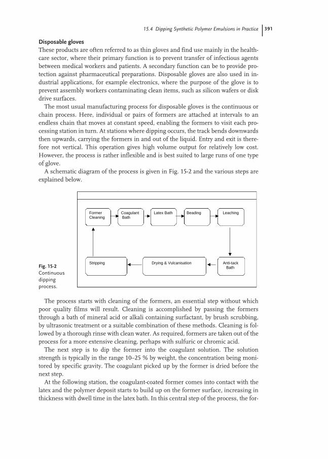
15.4 Dipping Synthetic Polymer Emulsions in Practice 391
Disposable glovesThese products are often referred to as thin gloves and find use mainly in the health-care sector, where their primary function is to prevent transfer of infectious agentsbetween medical workers and patients. A secondary function can be to provide pro-tection against pharmaceutical preparations. Disposable gloves are also used in in-dustrial applications, for example electronics, where the purpose of the glove is toprevent assembly workers contaminating clean items, such as silicon wafers or diskdrive surfaces.
The most usual manufacturing process for disposable gloves is the continuous orchain process. Here, individual or pairs of formers are attached at intervals to anendless chain that moves at constant speed, enabling the formers to visit each pro-cessing station in turn. At stations where dipping occurs, the track bends downwardsthen upwards, carrying the formers in and out of the liquid. Entry and exit is there-fore not vertical. This operation gives high volume output for relatively low cost.However, the process is rather inflexible and is best suited to large runs of one typeof glove.
A schematic diagram of the process is given in Fig. 15-2 and the various steps areexplained below.
The process starts with cleaning of the formers, an essential step without whichpoor quality films will result. Cleaning is accomplished by passing the formersthrough a bath of mineral acid or alkali containing surfactant, by brush scrubbing,by ultrasonic treatment or a suitable combination of these methods. Cleaning is fol-lowed by a thorough rinse with clean water. As required, formers are taken out of theprocess for a more extensive cleaning, perhaps with sulfuric or chromic acid.
The next step is to dip the former into the coagulant solution. The solutionstrength is typically in the range 10–25 % by weight, the concentration being moni-tored by specific gravity. The coagulant picked up by the former is dried before thenext step.
At the following station, the coagulant-coated former comes into contact with thelatex and the polymer deposit starts to build up on the former surface, increasing inthickness with dwell time in the latex bath. In this central step of the process, the for-
Fig. 15-2Continuousdippingprocess.
Former Coagulant Latex Bath Beading Leaching Cleaning Bath
Stripping Drying & Vulcanisation Anti-tack Bath

392 15 Applications for Dipped Goods
mer temperature, speed and smoothness of former entry and exit are important fac-tors in the production of an even, defect-free film.
On leaving the latex dip tank, the formers are lifted to the horizontal and rotated,to avoid ungelled latex on the outside of the film flowing to the bottom of the former.The latex layer continues to consolidate after removal from the latex bath, forming afirm, gelled coating.
The polymer at the cuff of the glove is then rolled on to itself by the action of me-chanical rollers or brushes, a process known as “beading”. The tack of the polymer atthis stage of processing is sufficient for the bead to be held in place. The purpose ofthe bead is to give the cuff of the thin glove adequate tear-resistance.
Following beading, the glove is leached, a washing process carried out by immers-ing the glove in warm (40–50 °C), clean water. Long leaching times are preferredfrom a technical standpoint, to achieve the maximum removal of water-soluble ma-terials. However, in practice, leach duration is limited by time, space and cost con-straints and is normally of the order of 5–10 min. Care must be exercised in theleaching process, since high leach water temperatures can promote excessive lengthdirection shrinkage of synthetic latices.
The glove is then dipped into an anti-tack compound, which may be a siliconeemulsion or a slurry of calcium carbonate. The purpose of applying this material isto reduce the rubber-rubber friction when the glove is ultimately peeled from the for-mer, thus easing its removal, and to prevent the interior surfaces of the glove stick-ing together on storage.
The penultimate stage of the process is drying and vulcanization. Sophisticatedcure ovens will allow the curing to be phased, for example to bring the temperaturegradually to around 120 °C to avoid blistering. A slightly cooler temperature may beprogrammed for the final oven stage, to make glove removal easier. For the curing ofdisposable gloves, approximately 20 min at 120 °C is required. Undercured glovestend to have low tensile strength and high elongation, making them difficult to strip.Incomplete drying can lead to problems of glove surfaces sticking to one another onstorage.
The removal of the glove from the former (“stripping”), is the only fully manualpart of the process, in which teams of three or four workers line each side of thechain to pull off and briefly check the gloves for holes. Occasionally compressed airjets are used to assist with the stripping process.
Disposable gloves can be further dried offline, by tumbling in heated ovens. Fol-lowing tumbling, gloves are usually chlorinated by immersion in an aqueous dilutechlorine solution (a technique also used for natural rubber disposable gloves). Thechlorine reacts with the surface layer of polymer molecules, giving a marked reduc-tion in surface tack that makes the gloves easier to don. Finally, the gloves may bewashed, re-dried, QC tested and packed.
Unsupported heavier weight glovesThicker walled gloves, capable of being used on multiple occasions, find use in bothindustrial and domestic situations. They are often made with a lining of small fibers(“floc lined”), which improves comfort by absorbing perspiration.

15.4 Dipping Synthetic Polymer Emulsions in Practice 393
Industrial gloves will probably be destined for use as protective equipment andwill therefore be required to meet specific safety standards. These standards cover ar-eas such as resistance to chemical penetration, puncture resistance and abrasion re-sistance. Further information on protective gloves is given in the book edited byMellström et al. [6].
Household gloves are normally made from natural rubber and have been regardedas price-driven commodity items. However, recent concern over protein allergy hasled to the increased use of sophisticated synthetic polymers in this area also.
Heavier weight gloves may be made by the continuous process in a similar man-ner to that described above, but they are more commonly produced by the batchprocess, outlined as follows.
Jigs to which perhaps 20 or 30 formers are fixed are moved sequentially on guiderails from station to station. Operations such as dipping into a liquid bath areachieved using hydraulic equipment. Within limits, the time spent at each stationcan be independently varied, so more control is possible than with the continuousprocess, where the speed of movement round the track is constant.
A schematic diagram of the batch process for thicker unsupported gloves is givenin Fig. 15-3.
The various steps in this process are described below and the similarities and dif-ferences in the production conditions compared to those used for disposable glovesare highlighted.
The process again begins with the cleaning of formers, using similar methods tothose employed in the thin glove process.
The coagulant solution is of a higher concentration and dip times are much longerthan those used for disposable gloves. The most common coagulant solution is aque-ous calcium nitrate at 30–40 % by weight. With the batch process, the formers enterand leave the coagulant at right angles to the solution surface, only moving in thevertical plane. After withdrawal from the coagulant, the formers are usually invertedto achieve a more uniform distribution of the solution over the surface.
After drying the coagulant, the former is dipped into the latex bath. As for thingloves, the critical factors of entry and exit rate and former temperature have to be
Fig. 15-3Batch dippingprocess.
Former Coagulant Latex Bath Leaching Flock Cleaning Bath Bath Adhesive
Stripping Chlorination Drying & Vulcanisation Flocking Bath Booth
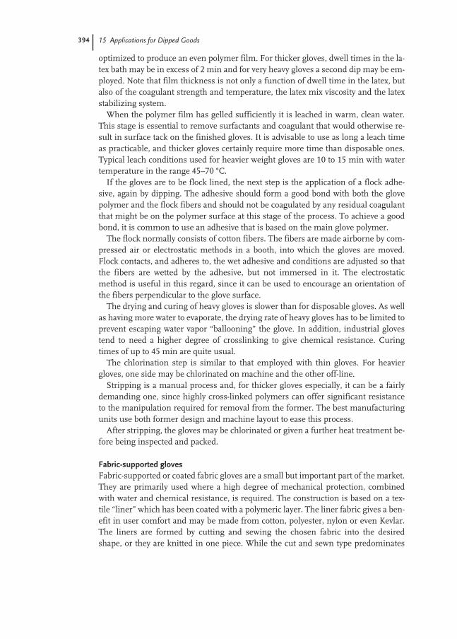
394 15 Applications for Dipped Goods
optimized to produce an even polymer film. For thicker gloves, dwell times in the la-tex bath may be in excess of 2 min and for very heavy gloves a second dip may be em-ployed. Note that film thickness is not only a function of dwell time in the latex, butalso of the coagulant strength and temperature, the latex mix viscosity and the latexstabilizing system.
When the polymer film has gelled sufficiently it is leached in warm, clean water.This stage is essential to remove surfactants and coagulant that would otherwise re-sult in surface tack on the finished gloves. It is advisable to use as long a leach timeas practicable, and thicker gloves certainly require more time than disposable ones.Typical leach conditions used for heavier weight gloves are 10 to 15 min with watertemperature in the range 45–70 °C.
If the gloves are to be flock lined, the next step is the application of a flock adhe-sive, again by dipping. The adhesive should form a good bond with both the glovepolymer and the flock fibers and should not be coagulated by any residual coagulantthat might be on the polymer surface at this stage of the process. To achieve a goodbond, it is common to use an adhesive that is based on the main glove polymer.
The flock normally consists of cotton fibers. The fibers are made airborne by com-pressed air or electrostatic methods in a booth, into which the gloves are moved.Flock contacts, and adheres to, the wet adhesive and conditions are adjusted so thatthe fibers are wetted by the adhesive, but not immersed in it. The electrostaticmethod is useful in this regard, since it can be used to encourage an orientation ofthe fibers perpendicular to the glove surface.
The drying and curing of heavy gloves is slower than for disposable gloves. As wellas having more water to evaporate, the drying rate of heavy gloves has to be limited toprevent escaping water vapor “ballooning” the glove. In addition, industrial glovestend to need a higher degree of crosslinking to give chemical resistance. Curingtimes of up to 45 min are quite usual.
The chlorination step is similar to that employed with thin gloves. For heaviergloves, one side may be chlorinated on machine and the other off-line.
Stripping is a manual process and, for thicker gloves especially, it can be a fairlydemanding one, since highly cross-linked polymers can offer significant resistanceto the manipulation required for removal from the former. The best manufacturingunits use both former design and machine layout to ease this process.
After stripping, the gloves may be chlorinated or given a further heat treatment be-fore being inspected and packed.
Fabric-supported glovesFabric-supported or coated fabric gloves are a small but important part of the market.They are primarily used where a high degree of mechanical protection, combinedwith water and chemical resistance, is required. The construction is based on a tex-tile “liner” which has been coated with a polymeric layer. The liner fabric gives a ben-efit in user comfort and may be made from cotton, polyester, nylon or even Kevlar.The liners are formed by cutting and sewing the chosen fabric into the desiredshape, or they are knitted in one piece. While the cut and sewn type predominates
15.5 The Testing of Synthetic Gloves 395
because of its ease of production, the knitted liner is finding increasing popularitybecause of the reduced material wastage, lower labor cost and increased comfort.
The dipping of supported gloves is carried out successfully by only a few compa-nies worldwide and the technology is generally proprietary. As there are many typesof supported glove and production methods vary, no attempt will be made to de-scribe their manufacture here in any detail. It can be said, however, that the key issueis to control the application of the polymer coating, so that good coverage and goodadhesion are achieved but without excessive penetration of fabric liner by the mix. Inaddition to fabric design, compound low-shear viscosity, compound surface energyand the depth and duration of dipping are some of the factors that can be used toachieve a successful over-dip.
The presence of a fabric liner creates some practical problems in the dippingprocess. With the correct control of latex compound rheology, straight dipping can,of course, be used. If a coagulant method is chosen, a significant amount of the co-agulant may be absorbed into the liner, requiring removal from the finished glove bythorough washing. The use of a heat-sensitized dipping compound is complicated bythe difficulty of achieving a controlled temperature at the liner surface and the diffi-culty of controlling the mix viscosity close to the liner in the presence of a hot former.In general, the coagulant and straight dipping methods are the most favored.
15.5
The Testing of Synthetic Gloves
An increasing number of standards concerned with the performance of gloves arebecoming available. They come from a variety of sources (regulatory bodies), includ-ing:
International International Standard Organization (ISO)USA American National Standards Institute (ANSI)
American Society for Testing and Materials (ASTM)UK British Standards Institution (BSI)France Association Française de Normalization (NF)Germany Deutsches Institut für Normung (DIN)Europe European Standards (EN)Former USSR State Committee for Standards (GOST)
Note that various professional organizations have also developed standards whichcan be useful for glove testing.
15.5.1
Non-safety-critical Gloves
There is a number of standards specifying the general performance of polymeric ma-terials which might be used in the manufacture of gloves. For example, both the

396 15 Applications for Dipped Goods
ASTM and BSI have issued methods for testing the physical properties of rubbersand the effects on rubbers of accelerated aging.
The ASTM has issued a standard for household or beautician’s gloves, which setsout specifications aimed at assisting in the achievement of performance consistency.Tests specified include tensile strength and elongation (before and after aging),physical dimensions and freedom from holes. This standard refers to general meth-ods for testing elastomeric materials, such as those mentioned in the preceding para-graph.
Gloves that are used in electronic assembly are designed primarily to protect theproduct under manufacture, rather than protect the worker. Some standards relatingto glove material cleanliness and to the testing of static electrical properties of mate-rials are available and used in this area.
15.5.2
Safety-critical Gloves
The hand is perhaps exposed to more hazards than any other part of the body. Thesehazards include physical damage, chemical contact and contact with biologicalagents. Clearly, one means of minimizing the risk of these hazards actually causingharm, is to select an appropriate glove.
There are many standards that specify tests and performance for protective gloves.The general tests relating to the physical properties of glove materials, referred toabove, may be used. The European Union has detailed a number of requirements forprotective glove manufacturers in the Personal Protective Equipment Directive89/686/EEC. Gloves meeting these requirements carry the CE mark, which allowsthem to be marketed throughout all European Community countries.
There are individual standards for assessing protection from mechanical, chemi-cal, biological and radioactive hazards, as well as protection from heat and cold. Par-ticular standards dealing with surgical and examination gloves exist, some of whichare material specific, and for gloves designed to give protection against electricalhazards.
Some of the standards that have found use in the protective glove area are listed inTabs. 15-4, 15-5 and 15-6.

15.5 The Testing of Synthetic Gloves 397
Tab. 15-4 North American standard test methods.
ASTM D120 E1 Standard Specification for Rubber Insulating GlovesASTM D412 Standard Test Methods for Vulcanized Rubber – tensionASTM D573 Standard Test Method for Rubber – deterioration in an air ovenASTM D624 Standard Test Method for Tear Strength of Conventional Vulcanized Rubber
and Thermoplastic ElastomersASTM D991 Standard Test Method for Rubber Property – volume resistivity
of electrically conductive and antistatic productsASTM D1418 Standard Practice for Rubber and Rubber Latices – nomenclatureASTM D3577 Standard Specification for Rubber Surgical GlovesASTM D3578 Standard Specification for Rubber Examination GlovesASTM D4679 Standard Specification for Rubber Household or Beautician GlovesASTM D5151 Standard Test Method for Detection of Holes in Medical GlovesASTM D5250 Standard Specification for Polyvinyl Chloride Gloves for Medical ApplicationASTM D5712 Standard Test Method for Analysis of Protein in Natural Rubber
and its ProductsASTM D6319 Standard Specification for Nitrile Examination Gloves for Medical ApplicationASTM E595 Standard Test Method for Total Mass Loss from Outgassing in a Vacuum
Environment
Tab. 15-5 European standard test methods.
BS/EN 368 Protective Clothing for Use against Liquid Chemicals – penetration of liquids
BS/EN 369 Protective Clothing for Use against Liquid Chemicals – permeation of liquids
BS/EN 374-1 Protective Gloves against Chemicals and Microorganisms – terminology and performance requirements
BS/EN 374-2 Protective Gloves against Chemicals and Microorganisms – determination of resistance to penetration
BS/EN 374-3 Protective Gloves against Chemicals and Microorganisms – determination of resistance to permeation by chemicals
BS/EN 388 Protective Gloves against Mechanical RiskBS/EN 407 Protective Gloves against Thermal Risks (heat and/or fire)BS/EN 420 General Requirements for GlovesBS/EN 421 Protective Gloves against Ionizing Radiation and Radioactive
ContaminationBS/EN 455-1 Medical Gloves for Single Use – specification for freedom from holesBS/EN 455-2 Medical Gloves for Single Use – specification for physical propertiesBS/EN 464 Protective Clothing – Protection against Liquid Chemicals – gas leak testBS/EN 511 Protective Gloves Against ColdBS 903 :A2 Physical Testing of Rubber – determination of tensile stress–strain propertiesBS 903: A9 Methods of Testing Vulcanized Rubber – determination of abrasion resistanceBS 903: C1 Methods of Testing Vulcanized Rubber – determination of surface resistivityBS 2782: Part 2 Methods of Testing Plastics – electrical propertiesBS 2782: Method 231A Methods of Testing Plastics – determination of surface resistivityBS 7506:1 Measurement in Electrostatics – guide to basic electrostatics

398 15 Applications for Dipped Goods
These lists are not intended to be exhaustive, but are included to give the readersome idea of the breadth of standards available. Clearly, as new technologies evolve,standards will be updated and others newly issued.
References
Tab. 15-6 Professional standard test methods
UK Dept of Health Specification for non-sterile NR latex examination glovesM.D.D. TSS/D/300.010Institute of Environmental Gloves and finger cots used in clean rooms and Sciences and Technology (USA) other controlled environmentsIES-RP-CC005.2
1 J. C. Carl, Neoprene Latex – Principles of Compounding and Processing, E. I. Dupont De Nemours, Wilmington,Delaware, USA, 1962.
2 D. C. Blackley, Polymer Latices Scienceand Technology, 2nd edn, Vol. 3, Chap-man and Hall, London, UK, 1997.
3 A. Lanham, N. Eidam, in: Wäßrige Poly-merdispersionen, D. Distler (ed.), Wiley-VCH, Weinheim, Germany, 1999.
4 D. M. Bratby, in: Polymer Latices and theirApplications, K. O. Calvert (ed.), AppliedScience, London, UK, 1982.
5 L. Ibarra, M. Alzorriz, Polym. Int. 1999,48, 580.
6 T Estlander, R Jolanki, L Kanerva, in:Protective Gloves for Occupational Use,G. A. Mellström, J. E. Wahlberg, H. I. Maibach (eds), CRC Press, Boca Raton, Florida, USA, 1994.
7 M. J. R. Loadman, Proc. Int. RubberConf., Manchester, UK, 1996.

399
aabrasion cohesion test Esso (ACTE) 323abrasion resistance 115, 332accelerators 389acorn structure 5acrylates 90acrylic adhesive 220acrylic dispersions 6, 12, 90, 108, 130 f., 142,
154, 193 ff., 217, 273 f., 285, 291, 358acrylic esters 90, 94additives 78, 132, 240, 332 f., 355adhesion 191 ff., 299, 330, 332, 338 f., 339adhesion level 210adhesion-elongation 238adhesive raw materials 192adhesives 191 ff., 334agglomeration number 28aggregates 332aging resistance 299American Standards (ANSI) 335analytical ultracentrifuge 51antifoam agents 6, 114, 136, 202antifreeze agents 235anti-sag 334apparel leather 284, 293applications tests 97 f., 114 f., 142 ff., 147 f.,
151, 156 f., 159 f., 168 ff., 210 ff., 221 f., 228 ff., 232, 237 f., 240, 246 f., 249, 261, 275 ff., 296 ff., 304 ff., 321, 335 ff., 368, 395 ff.
aqueous 1aqueous flexo news ink 121aqueous ink 104aqueous phase analysis 57asphalt binder 304asphalt composition 310asphalt consumption 301asphalt emulsion 302, 303, 313 ff.– anionic 315– application 314
– cationic 315– cured 318– ductility 317– elastic recovery 317– latex modified 318– medium-setting 313– modification 301– penetration 317– properties 309– rapid-setting 313– slow-setting 313– softening point 317– specification 304– tests 317– torsion recovery 317automotive coating 163 ff., 176 f., 183– appearance 169– basecoat 167– clearcoat 167– crosslinking 183– electrocoat 167– emulsion polymers 176– formulation 168– function of ingredients 168– function 167– layer 167– main ingredients 168– microgels 177– miniemulsions 177– performance 169– primer 167– standard tests 169automotive leather 284, 294average degree of polymerization 195
bback-coating of carpets 259, 262bally flexometer 297barrier coatings 7basecoat 173 ff., 287, 344
Index
400 Index
bending beam rheometer 306, 308bimodal 5binder 78, 84 ff., 127, 253, 291, 332– natural 90 f.– paints 127– sole binder 90– styrene-acrylate 96 f.– styrene-butadiene 95, 97– synthetic 90 f.binding strength 87, 92 ff.biocides 6, 135, 203biodegradability 6blistering 93 ff.block resistance 116board 92branching 18brightness 84, 86, 93butadiene 9, 90, 94 f.butadiene-styrene copolymers 11, 90, 256 ff.,
273 f., 285, 291, 303 ff.butadiene-acrylonitrite copolymers 385 ff.butyl acrylate 90
ccalcium carbonate 86 f.calender 85 f.capillary hydrodynamic fractionation 53capillary water absorption 345carboxylated styrene/butadiene (XSB)
dispersions 6, 90, 256 ff., 273 f.carboxylic acid 26carboxymethylcellulose 88, 90carpet 253carpet backcoating 259carpet backing 253carpet backing binders 253, 256, 258– carboxylated styrene-butadiene 256– cold SB (styrene-butadiene) 256– high solids styrene-butadiene latex
(HSL) 256– hot SB (styrene-butadiene) 256– natural latex 256carpet laminating 259, 263 f.– adhesive scrim coat 263– pre-coat 263– unitary backing 264carpet production 255carpet terminology 260cement 333cementitious topcoats 345centrifugation 51ceramic tile adhesives 238 ff., 332 ff.chain entanglement 21chain transfer 18
chain transfer agent 32, 178, 198characterization 41 ff.chelating agent 34chemical bonding 273chemical reacting adhesives 192chemical resistance 116china clay 86chip seal 316, 321– application test 321coagulant dipping 386coagulants 390coagulation 3coagulum 37coagulum grit 42coating 205coating color 81, 85, ff.– co-binder thickeners 87– pigments 86– sheet-fed offset 86coating layers 166coating of carpets 261coating support materials 205coating weight of adhesives 207co-binder 84, 87 ff.coefficient of friction 116colloid mill 313color 65concrete 242, 346 ff.– maintenance 347– rehabilitation 349– repair 347 f.construction adhesives 224construction industries 191contaminants 36conversion 22conversion process 363– melt rheology 363conversion-time curve 23core-shell modifiers 373core-shell structure 4 f.core-shell impact modifier 376core-shell particle 71corona discharge 118corona-pretreated film 218corrosion inhibitor 114CPVP 126cracking 336crinkle resistance 116critical micelle concentration
(CMC) 19, 27critical PVC 126critical surface tension 65cross-linking 4, 9, 21, 33, 70, 113, 167, 183 f.,
220

Index 401
cup and plate inks 120curtain coater 289 f.
ddecorative coatings 123 ff., 137, 139defoamer 6, 114, 136, 202degradation time 360delaminating 336delamination resistance 221density 43diafiltration 58dialysis 58differential scanning calorimetry 60dilatancy 45dipped gloves 388dipped goods 383dipping 384 ff.– forms 386– mix design 388– polymers 384– practical aspects 386– principles 385– process 383, 390 ff.direct print corrugated inks 119disc centrifuge 53dispersing aids 133, 235dispersion 1dissolution 66double-sided adhesive tapes 209Dougherty-Krieger equation 47dry adhesion 299dry mix mortars 333, 352dry mortar technology 332– pre-mixed 332– pre-packed 332– redispersible powders 332drying test 116dwell time 212dynamic light scattering 49dynamic mechanical analysis 63 f.dynamic shear rheometry (DSR) 306
eE.I.F. systems 342e-coat 170eco-efficiency analysis 323efflux time 44elastic modulus 62elastic recovery 237elasticity 6elastomeric roof coatings 247elastomeric wall coating 149 f.– application tests 151– formulation 150
electric double layer 26electrical tapes 208electrocoat 170 ff.electrokinetics 56electrolytes 33electrophoretic mobility 56elongation at break 6, 63elpo 170embrittlement 299emission measurement 230– chamber method 230emulsified asphalts 302emulsifier coverage 55emulsifiers 9emulsion polymerization 3, 16, 17, 20, 330,
356– at atmospheric pressure 16– at high pressures 16– mechanism 17emulsion 1emulsion polymers 15– synthesis 15emulsion vehicle 109engineering resins 375environmental impact 325equipment 39ethene 8, 10ethylene/vinyl acetate copolymers 6, 90,
330 ff.extenders 132extensibility 361exterior decorative coating 146 ff.– application tests 148– exterior exposure testing 148– formulations 147– performance tests 147– standard application tests 147exterior insulation and finish systems
(E.I.F.S.) 332exterior insulation systems 341exterior thermal insulation compounds
(E.T.I.C.S.) 332
ffastness 299fatigue cracking 306Fikentscher’s K-value 195, 360fillers 86, 202film formation 128 f.– coalescing agent 129– latex 128film forming emulsion polymer 117film morphology 70film whitening 67
402 Index
finish systems 341finishing 287finishing coats 287flexibility 332, 336, 338– mortar 338flexible 217, 330, 336– packaging 217flexing endurance 297flexographic 103– ink formulation 107– printing press 105flexural strength 332flocculation techniques 57flock lining 394floor-covering adhesives 224flow behavior 44flow curve 44flow, Newtonian 45flow, pseudoplastic 45foam backing 257foam impregnation 274foaming 6foaming behavior 48fogging test 300foil duct tapes 208folding carton inks 118food packaging 7form 386– dipping 386form cleaning 391– dipping 391formulation 86 f., 107, 117 ff., 141, 147 ff.,
150, 152 f., 156 f., 168, 171, 199 ff., 203 f.,219, 224, 227 f., 233, 236, 239, 243, 245, 249,263 f., 274, 388
free radical 18free-radical polymerization 25freeze-thaw 116, 245, 336– stability 48functional monomers 26furniture automotive 222furniture leathers 295fusion promotion 359
ggas chromatography 56gas permeation 68gel effect 21gel fraction 67gel permeation chromatography 69glass transition temperature 1, 6, 60, 94,
128, 154, 195, 288, 338, 357gloss 65, 93, 99, 112gloss enamel 142
glossy film lamination 219glove dipping 391, 393– batch process 393– continuous process 391gloves 384, 391 ff.– dipping 391– disposable 391– fabric supported 394– polymeric 391– protective 396– testing 395– unsupported 392gradient polymer elution chromato-
graphy 69grain impregnation 287gravure 103– ink 106– ink formulation 107– printing press 106– roll 206Green Label certification 227– of adhesives 227green strength development 230
hheat distortion temperature (HDT) 356heat resistance 116heat sensitivity 33Helio test 100high float emulsions 314hot light aging 300hot mix asphalt 302 f.hydration 337hydrodynamic particle diameter 50hydrophobicity 332
iimpact behavior 376impact modification 370impact modifiers 11, 367, 373, 375– non-weatherable 375– weatherable core shell 373impact performance 369, 372impact resistance 367impurities 35 f.induction period 21industrial maintenance coatings 155 ff.– application tests 156, 158– formulation 157– performance tests 156– salt spray testing 158inisurf 9initiation 18initiator 9, 31, 178
Index 403
– half-life 31– thermal decomposition 32– thermally dissociating 31initiator systems 30– half-life 30– peroxides 30– persulfate 30ink 93– absorption 93– additives 113– color strength 114– composition 106– for films 117– jet papers 81– splitting 97 ff.in-line injection 311interior decorative coating 139 ff.– adhesion test 144– application tests 142– block resistance 145– formulation 140 f.– freeze-thaw stability 142– heat age stabilitiy 142– interior flat coatings 140– performance test 145– print resistance test 145– scrub test 144– stability heat age test 142– stain resistance test 144– wall coatings enamels 140interior enamels 140internal surface area 3interparticle crosslinking 67, 70intrinsic viscosity 69isolation technology 356 f.
jjoint filling compositions 233
kkaolin clay 86, 87
llaboratory reactors 15laminating adhesives 217 f., 222laser light scattering 49latex 3– definition 3– paints 125lawn and garden bag inks 118layers 166– automotive coatings 166leather 283, 291– binder 291
– structure 283leather articles 292leather finishing 285 f., 296– test methods 296leather industry 283leather production 284letterpress 103life-cycle analysis 324light-fastness 300light transmission 49liquid soaps 7loaded wheel test (LWT) 322loss modulus 63low film forming temperature 112low temperature cracking 306lubrication 364
mmanufactures 12manufacturing processes 34– batch 34– continuous 34– plug-flow continuous reactor 34– semi-batch 35Maron plot 55masking tapes 209mastic products 231mechanical characterization 62mechanical stability 48medical diagnosis 7melt homogeneity 359melt rheology 363melt strength 361melt viscosity 362membrane filtration techniques 58membranes 350 f.– waterproof 350 f.metallic effect 186metallic flog (MF) index 182micellar nucleation 20micelles 19microgels 70, 177microorganisms 6, 203– protection against 203microscopic characterization 68microsurfacing 316, 321– application test 321– pavement 320Mie scattering 4milk carton ink 120milk carton wet rub 116mineral topcoats 344miniemulsions 177
404 Index
minimum film formation temperature(MFFT) 59, 128
model system 17modified fretting 323modifier shell effects 372modulus of elasticity 336moisture vapor transmission 247molecular weight 69, 127, 357monomer 23 f., 94monomers 23, 25 f.– butadiene 24– concentration 21– diene 24– fox equation 23– functional 26– major 23– polymer design 25– polymer properties 23– vinyl monomer 24mortar 239, 241 ff., 348 ff.mottling 93, 99multiple wall bags 121– inks 121
nnatural adhesives 192natural rubber latex 11, 303needlepunched carpet 255neoprene latex 303newspapers 121– inks 121non-weatherable impact modifiers 375non-weatherable PVC formulations 374non-woven manufacturing systems 270non-wovens 267 ff.– application tests 275– applications 268– binders 273– standard test methods 276notch sensitivity 370
oOEM coatings 164offset printing 82, 85, 93 ff.– rotogravure printing 93– sheet-fed 85 f.– web offset printing 93offset test 99oligomeric radicals 20opacifying aids 134– hollow sphere particles 134– TiO2 134opacity 82, 86, 93open time 113, 230
optical characterization 65organic pigments 107original equipment manufacturers
(OEM) 164– coatings 164
pP&I test 99packaging tapes 208paint formulations 125paints 127– binder 127paper coating 76, 79, 81, 84– coating colors 84– coating techniques 84paper gloss 84paper industry 75 f.paper machine 78paper products 120– inks 120paper properties 78paperboard coatings 75particle morphology 70particle size 48, 94 f.particle size distribution 52, 94, 331– dispersion/redispersion 331particle surface 54patch mortar 346paving 303, 313peel resistance 229– measurement 229peel strength 196, 210 ff.peel value 197performance grading 304 f.permanent deformation 306permanent paper label 203permeability 7permeation 66pH 43photon correlation spectroscopy 49pick strength 93– see binding strengthpigments 82 ff., 109, 132, 202– coat 288– dispersion 108– dispersion stability 104– extender 132– surface treatment 109– volume content of paints (PVC) 125 f.plastic materials 355– modification 355plasticizer 201, 286– migration 286plastics production 10
Index 405
plywood on lumber shear test 232polyacrylate dispersions 194, 291– leather-finishing 291polyacrylates 11polybutadiene dispersions 291polychloroprene adhesives 225poly-coated board 120polyken probe tack 214polymer characterization 68polymer colloids 1polymer compositions 129– binder 129– styrene-butadiene copolymers 129polymer corporation 131– acrylic copolymers 131– specialty monomers 131polymer design 25polymer dispersion 2 f., 10 ff., 41, 273– characterization 41– chemical bonding 273– commercial importance 10– definition 3– manufactures 12– names 2– properties 3– suppliers 13– synthesis 15polymer films 58polymer isolation technology 357polymer modified cement concrete
(PCC) 349polymer strength 6polymer/cement ratio 337– flexibility 337polymeric impact modifiers 355polymeric modifiers 358– classification 358– processing aids 358polymeric gloves 397– standard test 397polymerizable surfactants 30polymer-modified asphalt 309polymer-modified mortars 241polyolefins 10polystyrene 10polystyrene dispersions 7polyurethane adhesives 223polyurethane dispersions 7, 170, 172, 175,
179 ff., 191, 217 f., 222 f., 285, 288, 292polyurethanes 110polyvinyl acetate 90polyvinyl alcohol 88 ff., 332polyvinyl chloride 10porosity 93
pre-mixed 332pre-packed 332pre-print corrugated inks 119pressure sensitive adhesives 193, 205, 207,
210– test methods 210pressurized aging vessel (PAV) 304primer 172 f.– composition 173– formulations 152 f.– polymers used 172– requirements 172– surfacer 172primer coating 151 ff.– application tests 153– marker stain resistance 153– stain blocking 153print bonding 274printability 93printability tests 99printing 103printing inks 103, 115– tests 115printing processes 92, 103probe tack method 214process aids 355process conditions 37– branching 37– crosslinking 37– monomer/polymer concentration 37– number of particles 38– temperature 38processing aids 359 ff.– effect 366– for PVC 359– for resins 366– types 364product resistance 116propagation 18propagation rate 21propene 9 f.protective coatings 123, 154protective colloid 6, 9protective films 209protective gloves 384pulp 77 ff.pulp suspension 79pump-in 311PVC durables 373PVC formulations 371– for building products 371
406 Index
qquasielastic light scattering 49quick-stick 213
rraspberry structure 4, 5rate of polymerization 19, 21raw hide production 285raw materials 8reactive monomers 9recycling 10redispersible powders 329, 332, 339– adhesion 339– building materials 329– building/construction industry 329– dry mix mortar technology 329– premixed 329– pre-packed 329repair mortar 241, 346, 350residual volatiles 56residue characterization 319resin 104– support 110resinated pigments 109resistance to flow 237re-solubility 112reverse gravure 205re-wetting 116rheology control agent 181roll coating 289 f.rolling ball 215roof coating 248rosin fumarate ester 110rosin fumarates 104rotating thin film oven test (RTFOT) 304rotogravure printing 82 f., 86, 94, 99rubber milk 3rub-fastness 298rub test – metal corrugator 116rutting 306
ssafety 40– capacity limitation 40– design pressure 40– relief devices 40sand 333saturation 274scale-up criteria 15scrim coat 262sealant 233 f., 236 f.– production 237– slurries 351– tensile stress values 236
– types 235seed polymer 39seeded emulsion polymerization 20seeded processes 29selected conversion processes 364self-adhesive articles 210– labels 194, 205– products 199– tapes 207self-leveling underlayments (SLU) 345serum separation techniques 57shear strength 198, 210, 216, 229– measurement 216shear thinning 45shear value 197shoe upper leather 292shotcrete process 350silane-based coupling 235size press 79sizing agent 78, 80– low molecular weight 80– polymeric 80slot-die coating 207SLU 345, 347– abrasion resistance 347– surface 347slurry seal 316soap titration 55solids content 42solubility parameters 67solution polymers 113solution vehicles 112solvent based ink 103soy protein 90 f.spray drying 330, 357– emulsion polymerization 330spray-dry process 331spray dyeing 287spray machine 289spraying 289stability 47starch 79 ff., 88, 90 f.static light scattering 51steady shear viscosity profile 182steam cracker products 8storage modulus 63storage stability 48stress-strain measurements 62styrene 10, 90, 94styrene-butadiene dispersions 6, 90, 129,
204, 217, 256 ff., 273 f.styrene-butadiene rubber (SBR) latex 227,
256 ff., 303 ff.sub-floor mastics 231

Index 407
superpave binder specification 305superpave performance grade 304surface-active materials 27surface print inks 118surface sizing 76, 79 ff.surface tension 43surface tension of films 117surface treatment 108, 314– of pigments 109surfactant 27 ff., 114– physical properties 27– structural influences on properties 28surfmer 9swelling 66synthetic additives 78synthetic adhesives 192
ttack 6, 195, 210, 213tackifying resins 200tack measurement method 214tanning 283tensile strength 63termination 18test methods 97 f., 114 f., 142 ff., 147 f., 151,
156 f., 159 f., 168 ff., 210 ff., 221 f., 228 ff.,232, 237 f., 240, 246 f., 249, 261, 275 ff., 296 ff., 304 ff., 335 ff., 368, 395 ff.
thermoset coatings 183thick bed mortar technique 334thickeners 7, 84 ff., 133, 235, 390– anionic 235– dipping compounds 390thickening 201thin bed mortar technique 334thixotropy 45tile adhesives 240– test methods 240tile grouts 332, 334, 340 f.– ANSI Standards 341– EN Standards 341titanium dioxide 84, 86, 132 f., 147, 160,
202top coats 288, 341, 344torque rheometry 360toughness 63, 367towel and tissue ink 122traffic marking paints 158 ff.– application tests 159 f.– dry-through time 159– formulation 160– no-pick-up test 160– retro-reflectance 160transmission electron microscopy 70
transparency 6, 65tufted carpet 254 ff.
uunitary coating 264
vvario gravure 206vinyl acetate copolymers 6, 11, 90, 130, 141,
273 f., 330 ff.vinyl chloride 10vinylidene chloride 7viscosity 5 f., 45, 96, 182– dilatant 6– pseudoplastic 5– shear rate 5– thixotropic 5viscosity, Zahn efflux cup 117volatile organic compounds (VOC) 165, 258
wwall coatings 139wall mastics 231water based ink 103water impermeability 332water loss of green concrete 248water resistance 117water uptake 67water-borne binders 176– aqueous polyurethane dispersions 179– for automotive coating 179, 181– rheology control agents (RCA) 181– secondary acrylic dispersions 179water-borne coatings 163– applicaton properties 185water-borne emulsion polymers 124waterproofing membranes 244, 250, 350waterproofing sealing 351waterproofing system 350water-soluble binders 185– properties 185water-soluble oligomers 4wax emulsions 113weatherability 374weatherable impact modifiers 373web consolidation 272– chemical bonding 272– mechanical bonding 272– thermal bonding 272web formation 271– dry-laid 271– spun-laid 271– wet-laid 271wet adhesion 299

408 Index
wet finishing 286wet pick strength 94 ff.wet track abrasion test (WTAT) 322wetting 65wetting agents 201wetting aids 136white-point temperature 60workability 332work of fracture 63woven carpet 254 f.
yyellowing 94, 299Young’s modulus 62
zzeta potential 56Zosel tack measurement 215