polyurethane resin (pur) injection for rock mass and
TRANSCRIPT

Missouri University of Science and Technology Missouri University of Science and Technology
Scholars' Mine Scholars' Mine
International Conference on Case Histories in Geotechnical Engineering
(2008) - Sixth International Conference on Case Histories in Geotechnical Engineering
14 Aug 2008, 2:15pm - 4:00pm
Polyurethane Resin (PUR) Injection for Rock Mass and Structure Polyurethane Resin (PUR) Injection for Rock Mass and Structure
Stabilization Stabilization
Matthew J. DeMarco Central Federal Lands Highway Division, FHWA, Lakewood, CO
Follow this and additional works at: https://scholarsmine.mst.edu/icchge
Part of the Geotechnical Engineering Commons
Recommended Citation Recommended Citation DeMarco, Matthew J., "Polyurethane Resin (PUR) Injection for Rock Mass and Structure Stabilization" (2008). International Conference on Case Histories in Geotechnical Engineering. 35. https://scholarsmine.mst.edu/icchge/6icchge/session07/35
This work is licensed under a Creative Commons Attribution-Noncommercial-No Derivative Works 4.0 License.
This Article - Conference proceedings is brought to you for free and open access by Scholars' Mine. It has been accepted for inclusion in International Conference on Case Histories in Geotechnical Engineering by an authorized administrator of Scholars' Mine. This work is protected by U. S. Copyright Law. Unauthorized use including reproduction for redistribution requires the permission of the copyright holder. For more information, please contact [email protected].

Paper No. 7.07a 1
POLYURETHANE RESIN (PUR) INJECTION FOR ROCK MASS AND STRUCTURE STABILIZATION
Matthew J. DeMarco Central Federal Lands Highway Division, FHWA Lakewood, CO-USA 80228 ABSTRACT The Federal Lands Highway Division (FLH), FHWA, is currently investigating the application of polyurethane resin (PUR) injection as a rapidly deployed, cost-effective ground stabilization measure providing superior stabilization performance, while achieving aesthetics objectives. Most recently, in cooperation with the Colorado Department of Transportation (CDOT), FLH completed full-scale PUR demonstration projects at a historic tunnel located along SH 14 in the scenic Poudre Canyon west of Ft. Collins, CO, and at a dry-laid stone masonry wall supporting SH 149 along the Rio Grande River west of South Fork, CO. The Poudre Canyon demonstration involved the “gluing” of a previously bolted section of the western tunnel portal where annual freeze/thaw cycles and rock mass creep toward the adjacent Cache La Poudre River were contributing to rock mass instability. The South Fork demonstration involved PUR injection within a highly-porous, actively failing and culturally-sensitive dry-laid stone masonry wall – a type of retaining structure commonly encountered throughout federal park and forest lands. Based on these investigations, application guidance is being developed for the selection of polyurethane resin products and injection methods when (1) stabilizing failing groundmasses (e.g., rock slopes, unique rock promontories, escarpments), and (2) preserving aging and/or deteriorating man-made structures (e.g., historic retaining walls, archeologic structures). INTRODUCTION The Federal Lands Highway Division (FLH) of FHWA is responsible for the construction and rehabilitation of scenic roadways in America’s most environmentally and culturally sensitive settings. As good stewards of U.S. public lands roadway projects, preservation of unique natural features and historic and archeologic structures is central to the FLH “Lightly on the Land” construction philosophy. To further support preservation of our public lands resources, FLH has sought, through its Technology Deployment Program, ground stabilization technologies that…
(1) Provide superior stabilization and preservation of natural, archeologic, and historic structures subject to environmental and roadway construction damage;
(2) Produce aesthetically pleasing results in context-sensitive settings (particularly technologies that are virtually invisible to the public); and
(3) Provide cost-effective alternatives to traditional blasting-scaling-bolting operations – which are often expensive, time consuming, environmentally invasive, publicly adverse, and which may result in less-than-desirable constructed/excavated features requiring follow-on aesthetic treatment.
Polyurethane resin (PUR) injection, or “rock gluing”, a long-established method for rapidly stabilizing weak, actively failing ground in the underground mining industry, is one such technology readily transferable to FLH highway projects (sample shown in Fig. 1).
Fig. 1. Rock fragments permanently bonded within hardened polyurethane resin (PUR).

This simple, two-part, polymer resin is easily transported and stored, readily pumped into fractured rock and/or porous manmade structures, provides superior stabilization/sealing with very short set and cure times, is environmentally friendly when set, and results in aesthetically pleasing site conditions. Although technology transfer to the civil transportation sector has been slow compared to more conventional ground stabilization methods (e.g. rock bolting, cementitious grout), this technology becomes quite cost-effective when addressing the aesthetic requirements common to FLH roadway projects – where external rock and structure rehabilitation fixtures cannot be tolerated, and where applications cover relatively confined, limited areas. The FLH Technology Deployment Program is currently investigating and documenting applications of the PUR technology as a rapidly deployed, cost-effective ground stabilization measure providing superior stabilization performance, while achieving aesthetics objectives. During the summer of 2006, in cooperation with the Colorado Department of Transportation (CDOT), FLH completed a full-scale PUR demonstration project at a historic tunnel located along SH 14 in the scenic Poudre Canyon west of Ft. Collins, CO (Fig. 2). The demonstration involved the “gluing” of a previously bolted section of the western tunnel portal where annual freeze/thaw cycles and rock mass creep toward the adjacent Cache La Poudre River were contributing to portal instability. Over the course of six days, a three-man crew working out of a lift drilled twenty three, 10-12 ft deep holes above the western portal and outboard tunnel abutment, through which 6,000 lbs of PUR were successfully injected. The PUR infused throughout the rock mass, evidenced by small amounts of resin dripping from surface joints and fractures, effectively stabilizing and sealing the portal area.
Fig. 2. PUR injection at the west portal of the Poudre Canyon Tunnel, along the Cache La Poudre River on SH 14.
In addition to the Poudre Canyon demonstration, FLH has recently completed a second PUR injection demonstration involving the stabilization of a culturally-sensitive, dry-laid stone masonry retaining wall supporting SH 149 west of South Fork, CO, adjacent to the Rio Grande River (Fig.3). Whereas the Poudre Canyon Tunnel demonstration involved PUR injection throughout a relatively large volume of moderately jointed and fractured rock, the South Fork retaining wall project focused on evaluating injection methods within a highly porous, highly unstable structure. Of particular interest to this investigation was whether PUR could be successfully delivered to target zones within the wall mass, if resin could be pumped without further damaging the wall or initiating failure, and if PUR outflows along the face could be effectively managed to minimize required cleanup and aesthetics impacts.
Fig.3 Drilling prior to PUR injection behind a dry-laid stone masonry retaining wall along SH 149 west of South Fork, CO. Although it was not possible to implement full-scale performance/proof testing at these demonstration sites, qualitative observations coupled with years of rock mass stabilization experience in the underground mining industry suggest significant gains in rock mass and structure stabilization were achieved. Both demonstrations resulted in a number of “lessons learned” which will serve as guidance for future applications on FLH projects.
Paper No. 7.07a 2

POLYMER PRODUCTS AND PUR APPLICATIONS
lthough polyurethane resins encompass a broad spectrum of
verview of Polymer Products
Aproduct specifications, they represent a fraction of the even broader range of polymer products available for sealing, bonding, stabilizing, and consolidating porous materials. With this in mind, the FLH Technology Deployment Program has focused on those product specifications most suitable for rock mass and historic structure stabilization – paying particular attention to product performance attributes and operating constraints, system delivery methods, product cost, potential environmental impacts, and the technical benefits compared to more traditional stabilization options. In light of program findings to date, this section provides a brief overview of polymer products, specific attributes of polyurethane resins deemed beneficial to rock and structure stabilization, the range of current applications in the civil and mining industries, a comparison with traditional cementitious grout applications, and an overview of potential environmental issues. O
here exist literally tens of thousands of different mix designs
he following briefly overviews the aforementioned
olyurethane (PU).
Tcomprising the family of polymer products inclusive of polyurethanes (PU), polyurethane resins (PUR), and epoxy resins (EP). Although sometimes difficult to distinguish one product from another, as terminology is often used interchangeably to describe these products, they can be broadly defined by several key characteristics: density, strength, reactivity with water, expansion/elongation, shrinkage, number of mixing stages, and relative product cost. Of these characteristics, water interaction is of principal interest when selecting the proper polyurethane product for ground/structure stabilization – a fact illustrated by the demonstration projects described later in this paper. Tcharacteristics of PU, PUR and EP products. Due to the wide range of products available, application and material property information should be obtained from suppliers and carefully considered prior to final product selection. P Polyurethanes are extremely versatile
s with all urethanes, foams are produced when reacting two
EP products.
urethanes (PU)
plastics, and are found in a variety of forms: flexible or rigid foams, solid elastomers (or rubbers), coatings, adhesives and sealants. Although generally considered thermoset plastics, those that permanently harden upon heating/curing, there are grades of polyurethane elastomers that are thermoplastic – softening upon heating and then hardening once cooled without appreciable change in chemical composition. Aprincipal components, polyols and isocyanates. In practice, this product can be stored fully mixed and injected in a single-stage process, greatly simplifying PU application. PU reaction set-times can be varied from as little as 15 seconds to several hours, depending on accelerant additives. Table 1 lists additional relative PU properties when compared to PUR and
Table 1. Relative properties of polyurethane foams (FHWA, 2007).
PolyInjection Type Foam/Gels/Grouts Density 3 to 50 pcf Comp./Tensile Strength 10 to 500 psi Component Mixing ne-Stage Generally OInjection Pressure 100 to 3,000 psi Expansion 25% to 3,000% Elongation 10% to 500% Shrinkage 1% to 10% UV Reactivity High Relative Cost Low Water Reactivity phillic Hydro
PU nsidered illic, aggressively
teracting with water to foam upwards of 3,000% of the ’s are generally co to be hydroph
inoriginal volume, and may elongate as much as 500%. PU’s can also shrink in excess of 10% if allowed to thoroughly dry. Because this polymer type incorporates water within its chemical structure, PU will shrink and swell indefinitely with groundwater fluctuations. In addition, as density decreases with product expansion, shear strength also greatly decreases. For these reasons, PU’s are typically used in water sealing applications, and not relied upon for high adhesion strength or groundmass consolidation in high load settings. However, when PU is injected under confined conditions significant expansion pressures can be generated extending the use of this product to a variety of structure jacking applications. Polyurethane Resin (PUR). Polyurethane resins differ from
olyurethane foams primarily in terms of their strength, two-
:1 mixing/injection stem. “A” and “B” components, each with a viscosity
pstage mixing requirements, and reactivity with water. PUR is significantly stronger than PU, attaining compressive/tensile strengths exceeding weak-to-moderate intact rock strengths while exhibiting very high adhesion. In fact, removing this product from most rock surfaces following initial set typically requires hammering or grinding, often taking a veneer of the rock in the process. As a result of the high adhesion strength of this “glue” product, PUR has been used to stabilize failing groundmasses in underground mining environments throughout the U.S. since the mid-1970’s. PUR generally consists of a two-stage, 1sysimilar to a light oil, are pumped in separate lines until the point of injection, where mixing is facilitated by spiral inserts within the injection nozzle. Reaction set times vary from less than a minute to several hours, and are greatly influence by line and ground temperature. For example, the PUR product used during the demonstrations described later in this paper had an effective working injection temperature range from 50oF to approximately 95oF, resulting in set times ranging from several minutes to 15-20 seconds, respectively. Although initial set times can be very quick, with 90% strength achieved in less than 1 hr, full cure is commonly specified at 24-48 hours. It is, therefore, important to
Paper No. 7.07a 3
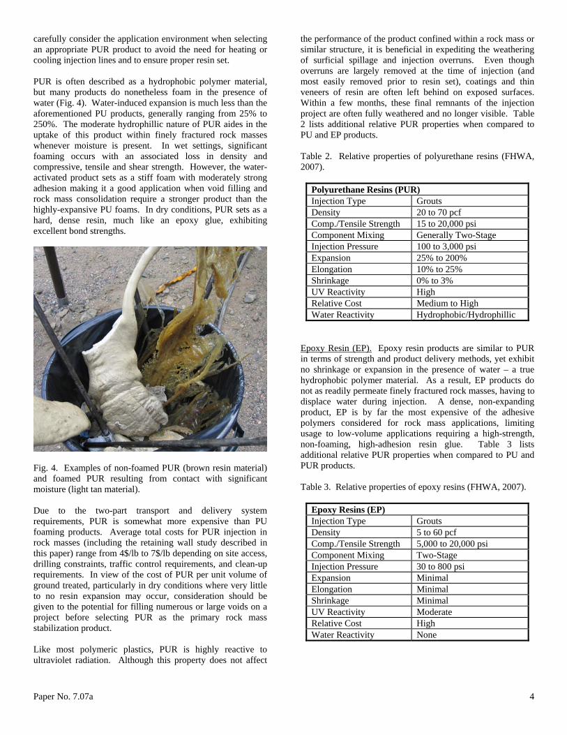
carefully consider the application environment when selecting an appropriate PUR product to avoid the need for heating or cooling injection lines and to ensure proper resin set. PUR is often described as a hydrophobic polymer material,
ut many products do nonetheless foam in the presence of
nd foamed PUR resulting from contact with significant
sport and delivery system quirements, PUR is somewhat more expensive than PU
plastics, PUR is highly reactive to ltraviolet radiation. Although this property does not affect
perties of polyurethane resins (FHWA, 007).
urethane Resins (PUR)
bwater (Fig. 4). Water-induced expansion is much less than the aforementioned PU products, generally ranging from 25% to 250%. The moderate hydrophillic nature of PUR aides in the uptake of this product within finely fractured rock masses whenever moisture is present. In wet settings, significant foaming occurs with an associated loss in density and compressive, tensile and shear strength. However, the water-activated product sets as a stiff foam with moderately strong adhesion making it a good application when void filling and rock mass consolidation require a stronger product than the highly-expansive PU foams. In dry conditions, PUR sets as a hard, dense resin, much like an epoxy glue, exhibiting excellent bond strengths.
Fig. 4. Examples of non-foamed PUR (brown resin material)
amoisture (light tan material). Due to the two-part tranrefoaming products. Average total costs for PUR injection in rock masses (including the retaining wall study described in this paper) range from 4$/lb to 7$/lb depending on site access, drilling constraints, traffic control requirements, and clean-up requirements. In view of the cost of PUR per unit volume of ground treated, particularly in dry conditions where very little to no resin expansion may occur, consideration should be given to the potential for filling numerous or large voids on a project before selecting PUR as the primary rock mass stabilization product. Like most polymeric u
the performance of the product confined within a rock mass or similar structure, it is beneficial in expediting the weathering of surficial spillage and injection overruns. Even though overruns are largely removed at the time of injection (and most easily removed prior to resin set), coatings and thin veneers of resin are often left behind on exposed surfaces. Within a few months, these final remnants of the injection project are often fully weathered and no longer visible. Table 2 lists additional relative PUR properties when compared to PU and EP products. Table 2. Relative pro2
PolyInjection Type Grouts Density 20 to 70 pcf Comp./Tensile Strength ,000 psi 15 to 20Component Mixing o-Stage Generally TwInjection Pressure 100 to 3,000 psi Expansion 25% to 200% Elongation 10% to 25% Shrinkage 0% to 3% UV Reactivity High Relative Cost High Medium toWater Reactivity phobic/Hydrophillic Hydro
poxy Resin (EP).E Epoxy resin products are similar to PUR terms of strength and product delivery methods, yet exhibit
e properties of epoxy resins (FHWA, 2007).
inno shrinkage or expansion in the presence of water – a true hydrophobic polymer material. As a result, EP products do not as readily permeate finely fractured rock masses, having to displace water during injection. A dense, non-expanding product, EP is by far the most expensive of the adhesive polymers considered for rock mass applications, limiting usage to low-volume applications requiring a high-strength, non-foaming, high-adhesion resin glue. Table 3 lists additional relative PUR properties when compared to PU and PUR products. Table 3. Relativ
Epoxy Resins (EP) Injection Type Grouts Density 5 to 60 pcf Comp./Tensile Strength 20,000 psi 5,000 toComponent Mixing Two-Stage Injection Pressure 30 to 800 psi Expansion Minimal Elongation Minimal Shrinkage Minimal UV Reactivity Moderate Relative Cost High Water Reactivity None
Paper No. 7.07a 4

Civil and Mining PUR Applications
epoxy resins have long een used in the civil construction industry. General
embranes: Spray-on polymers have been used successfully in the tunneling industry as both
often used to fill
U products have been used
U.S. to repair and seal cracked
Poly e been used in the U.S. since t least the mid-1970’s; however, their application has largely
ric constraints, required progression of PUR injection, and
ydrophillic PUR product for
nd bedding planes
jection in
iling ground conditions (note small-diameter injection rod
fairly high pressures in nderground settings to minimize drilling requirements,
Polyurethane foaming products andbapplications include crack sealing, establishing water/gas barriers, void filling, structure jacking and material bonding. More specifically, the following types of examples may be found in use today: PU Spray-On M
temporary and permanent measures to support loose, raveling ground. Comparisons to conventional shotcrete applications indicate that spray-on polymers exhibit 2 to 10 times the tensile strength of shotcrete at half the application thickness. Although not commonly used in place of shotcrete, thin coatings of spray-on polymers are often used immediately following excavation in soft ground to control both rock ravel and water seepage prior to initial girder-mesh-shotcrete support. PU Void Filling: Due to the aggressive hydrophillic nature of polyurethane products, PU is suspected or known voids behind permanent tunnel lining systems and foundations – particularly those involving water seepage. The PU foams and sets quickly, minimizing product loss in flowing water conditions and quickly sealing seeping voids. PU Subgrade Improvement/Slab Jacking: Two-component, highly expansive Pextensively in the U.S. to fill voids beneath pavement and to raise slabs to correct joint faulting and/or slab settlement. This one of the more common uses of PU in the civil industry today. EP Structural Foundation Sealing and Repair: EP has long been used in the structural foundations where a low-viscosity, high-strength product is required in relatively small volumes of application. These applications generally do not involve significant water seepage, and do not require void filling or structure consolidation.
urethane resin products havabeen limited to stabilizing weak and failing ground masses within the underground mining industry. Several million pounds of PUR are injected annually in U.S. underground coal mining operations alone – serving to reinforce, consolidate and seal large volumes of overhead rock. For many of the largest U.S. mining companies, PUR injection has become a staple technology for rehabilitating critical roof fall areas, stabilizing weak roof strata during longwall ground support recovery operations, stabilizing/sealing geologic anomalies (e.g., fault and shear zones, ancient sand channels), and managing/mitigating water inflows (Fig. 5). In all cases, successful PUR applications in mining are dependent on carefully considering several key attributes of the setting: Site Accessibility: Site access considers geomet
the potential need for primary and/or supplemental ground support installation. Presence/Absence of Groundwater: Groundwater inflows may require the use of a hrock mass sealing; however, consideration should be given to the potential for creating hydrostatic heads sufficient to destabilize the rock mass. Minor groundwater conditions lend themselves to hydrophobic/mildly-hydrophillic PUR products with greater installed densities and strength. Rock Mass Permeability: The location, extent and character of rock mass discontinuities adetermines how far the resin will transport through the rock mass, what volume of PUR may be needed, and what extent drilling may be required to ensure resin permeates critical support zones. For example, PUR may readily travel along bed separations in delaminating sedimentary rock masses, but may not migrate throughout layered strata without extensive cross-measure drilling. Air/Rock Temperature: Rock temperatures are relatively stable and within operating ranges for PUR inmost underground operations. However, air temperatures within the mine can fluctuate greatly depending on the time of year and mine ventilation requirements.
Fig. 5. PUR injected into coal mine roof and rib to stabilize faextending from corner of opening). Typically, PUR is pumped under uexpedite PUR installation in time-sensitive settings, and ensure migration throughout the rock mass within 10-20 ft of the injection hole. The low viscosity of many PUR products allows permeation through crack apertures as narrow as 0.04 mm. Staged pumping allows filling of larger discontinuities first, with latter stages permeating the finer fractures. PUR Versus Cementitious Grout PUR and cementitious grouts are best compared on the basis of density, viscosity, strength, set-up time, and installed cost:
Paper No. 7.07a 5

Density: Polymer products can be customized to achieve
ast set times are used to
eaker, ranging in strength from 100 to
to set within seconds to several
grouts versus
In glow ost grouting is required.
UR’s are generally more applicable when high-strength,
a much broader range of installed densities than cement or silica grouts. However, predicting and controlling resin expansion in variable moisture conditions with mildly-hydrophillic products is difficult. This is an important consideration when attempting to stabilize failing structures that cannot withstand even small deformations associated with PUR expansion. Viscosity: Polymer products generally have much lower viscosities than cement or silica grouts, allowing permeation into fine fractures. Fconstrain PUR migration from the injection point, and staged pumping is used to direct the product throughout the rock mass. Strength: The strength of fully cured cement grouts ranges from 2,500 to 5,000 psi; silica grouts are substantially w1,000 psi. Conversely, PUR strengths typically range from 10,000 to 20,000 psi, with much higher bond adhesion strengths. Set-Up Time: Initial set for cement and silica grouts ranges from hours to days, whereas polyurethane resins can be customizedminutes – generally achieving 90% strength in about an hour. PUR’s are temperature sensitive, with large fluctuations resulting in widely varying set times. Care must be taken to ensure line and ground temperatures are within the manufacturers specifications. Installed Cost: Generally, cement and silica grout installed costs are substantially cheaper than PUR per unit volume ($15-$30/cuft installed for cement$120-$150/cuft installed for PUR). However, equal volumes of these products may not be applied to a given setting to achieve the same results. For example, large voids in a dry-laid retaining structure may be filled with a low-strength cement grout to help consolidate the rock mass. In dry conditions, a much smaller volume of PUR may be injected to coat the internal rock structure and increase bond at rock contacts without filling an appreciable portion of the void volume. In this case, the installed cost may be similar, but greater strength gains may be realized with the PUR.
eneral, cement/silica grouts are used where high-volume, -to-moderate strength, lower c
Plower volume, broader transport, and faster set time conditions are warranted. Environmental Issues PUR products, in the thermoset cured form, are generally inert
, and are commonly used in potable ater containment and food preparation/storage applications.
ugh most applications are well protected ithin natural rock or man-made structures, FLH projects
e currently no nvironmental pollutant concerns identified with UV
JECTS
s previously mentioned, over the past couple of years FLH emonstration projects
ith the Colorado Department of Transportation (CDOT).
and chemically stablewHowever, the isocyanate component and solvents used to control set times in the polyol resin component possess varying degrees of toxicity depending on mix formulation, and may contribute pollutants to groundwater in their component form. In general, both components are considered mildly to
moderately toxic, and are easily containable on project sites within clearly labeled 55-gal drums connected to a closed pumping system. Some resin mixtures are highly flammable both before and after set. Althowhave given consideration to the effects forest fires may have on near-surface PU slab-jacking installations. As previously mentioned, ultraviolet light (UV) degradation does impact polymer products. There aredegradation of cured PUR. In practice, very small quantities of inert PUR surficial overrun (in a cured thermoset plastic state) are left to degrade within the environment, ultimately resulting in a non-visible application with no environmental impact. Biodegradation from microbial or fungal attack has also been documented in instances involving specific polyester-based PUR products. PUR DEMONSTRATION PRO Ahas undertaken two cooperative PUR dwThe first was conducted at a historic tunnel located along SH 14 in Poudre Canyon, just west of Ft. Collins, CO. This site was selected due to its similarity to traditional mining PUR applications (jointed rock mass injection), and because it represented a historic rock mass structure that might easily be found within the domain of an FLH partner agency (e.g., National Park Service, U.S. Forest Service). The second project involved the stabilization of a culturally-sensitive, potentially historic, dry-laid stone masonry wall supporting SH 149 just west of South Fork, CO, along the Rio Grande River valley. This site was selected in response to numerous requests from FLH partner agencies regarding the ability of PUR to stabilize historic and/or archeologic structures. In fact, stabilization of historic retaining wall assets may well turn out to be the major application of PUR injection within the FLH roads program. Poudre Canyon Tunnel In June 2006, FLH demonstrated the application of PUR
stabilization within the western portal f the Poudre Canyon Tunnel, located on SH 14 along the
injection for rock mass oscenic Cache La Poudre River in northern Colorado (Fig. 6). The tunnel is a very short, 75-ft-long, drill-and-blast, two-lane rectangular excavation through a vertically foliated gneiss and metabasalt. Widely spaced random jointing occurs within the rock mass; however, discontinuities and foliation are favorably aligned relative to the tunnel drivage, requiring no artificial support or lining within the tunnel. However, the vertical foliation does create freeze/thaw rockfall problems at either portal (foliation-defined rock “plates” peel from above the portal), requiring the implementation of a spot bolting
Paper No. 7.07a 6

program within the overlying western portal rock mass and along the outboard portal abutment in 2001 (Fig. 7). It was felt that this test location would greatly benefit from additional ground reinforcement and fracture sealing, and would be somewhat protected from injection-induced rockfall by the existing tension-bolt installations.
Fig. 6. PUR injection work in the bolted section above the western tunnel portal.
Fig. 7. Close-up of the foliation joint-defined blocks above the western portal. FLH procured PUR injection services from Micon Mining, Grand Junction, CO. Micon is the leading provider of PUR
jection services to the underground mining industry, and has
Micon RokLok 70
inover 30 years experience with resin injection and rock mass stabilization in a wide range of rock types and application settings. Their RokLok 70 PUR product was selected based on its strength, viscosity, mild-hydrophillic nature, and broad operating temperature range. Table 4 lists some of the pertinent physical properties of the RokLok 70 product.
Table 4. Properties of Micon RokLok 70 polyurethane resin.
Average Set Time 2 min. 90% Strength 1 hr. Full Cure 48 hrs. Density 70 pcf Compressive Strength psi (viscous yield) 10,200 Compressive Modulus 0 psi 92,00Flexural Strength si 10,900 pFlexural Modulus 313,000 psi Tensile Strength 3,850 psi Shear Strength 530 psi Shear Modulus 7,100 psi % Elongation ∼17 %
Pe and finding ject include the fo
Twenty three 1.5-in-diameter holes were drilled 8-10 ft
La Poudre River) and overlying rock mass. Drilling and PUR injection was completed in six working
sulting in minimal traffic delays.
tely 12 total barrels of A/B
Fig. 8. Component “A” and “B” barrels and two-sided pump.
rtinent details s of the prollowing:
deep within the portal outboard abutment (bounded by the Cache
days. All drilling was accomplished with a pneumatic rotary-percussive, hand-operated jackleg drill, operated from a man-lift. Holes were generally completed in 20-25 minutes, re
All holes were injected immediately following drilling to eliminate the possibility for cross-contaminating pre-drilled holes, and allowing hole-by-hole results to dictate the ultimate injection layout.
200 to 500 lbs of PUR was injected in each hole, for a total of 6,000 lbs of PUR used on the project. Each 55-gallon barrel contains 500 lbs of component product, therefore requiring approximacomponents to complete the job (Fig. 8).
Paper No. 7.07a 7

Approximately 850 sqft of portal area was treated to an estimated average depth of 10 ft, for a total approximate treated volume of 8,500 cuft (∼0.75 lbs/cuft of rock mass treated).
Coupled, 3-ft-long hollow injection rods, with a short packer/mixing assembly attached at the resin delivery end, were inserted to within a few feet of the back of the hole (approximate 6-8 ft depth). Packers were generally seated fairly tightly during installation, but can accommodate up to 2-in-diameter holes during pumping, if needed. The innermost rod and attached packer assembly were resin-anchored within the hole by the conclusion of the injection process, and were abandoned in the hole by disconnecting at the coupler.
Relatively small volumes were pumped (1-4 gpm) under low pressure (<50 psi) until PUR overrun was observed. Pumping was then suspended for approximately 1 minute, allowing the PUR to begin to set prior to resuming
ely sealed the lower portion of the
Fig.
jection e rock mass. Note that me of the resin is foaming due to moisture in the surface
fractures. A majority of the rock mass discontinuities appeared to be
filled with hard, non-expanded, dense resin. Foamed resin was seen coming from rock mass discontinuities
Hard, dense, high-strength resin fully filling major ck
erification drilling was conducted to determine what level
ime tests on rock samples at the site, oupro
fullysubsThis
Ohigh
located near the overlying slope surface and beneath slope vegetation – areas with higher moisture contents (Fig. 10).
pumping. Staging the pumping in this manner allowscracks to be sealed, thereby pushing the next volume of PUR delivered along other fracture and joint paths. Work progressed from bottom-to-top. Initial PUR injection would flow down through the rock mass until the rapid set effectivrock mass. Continued pumping would then cause the PUR to work its way upward within the rock mass above the installation hole (Fig. 9). In most cases, PUR migration was confined to an approximate 4-8 ft radius around the installation hole. However, more persistent discontinuities with wide apertures could easily convey resin 10-15 ft prior to initial set.
9. Typical migration of PUR injection from below the point, upwards through thin
so
ig. 10. Fro mass discontinuity.
Despite the volume of resin pumped within the portal area, no rockfall occurred during or following PUR injection as a result of injection pressures or resin expansion in wet zones.
Traffic was stopped during all drilling and injection operations, with average delays running about 30 minutes. Vehicles were kept well back from the injection operation to avoid fine PUR “strands” occasionally squeezing from fine cracks during pumping from landing on andpermanently affixing to car exteriors.
No significant overruns were encountered. Cleanup involved rapidly peeling PUR drips and runs from the rock mass prior to set, or chipping hardened overruns from the rock surface with hand tools (Fig. 11). Injection holes were completed with dark-colored grout. A few months after the project was completed it was nearly impossible to see that any work had been done at the site.
The total cost of the project, less traffic control provided by CDOT, was ∼$42K, or about $7 per installed lb of PUR.
No vof volumetric coverage may have been attained or the nature of the resin product within discontinuities (hard resin or foamed resin). Resin set tc led with visual observation of the progression of the resin th ughout the rock mass (and out several of the supposedly
-grouted bolt installation holes) indicated that a tantial volume of the rock mass was securely reinforced. empirical performance assessment was sufficient for
CD T to recommend the use of this product on other state way projects during the summer of 2007.
Paper No. 7.07a 8

Fig. 11. Overruns are relatively easy to remove if tackled before initial set is complete. South Fork Retaining Wall In September 2007, FLH evaluated the potential application of
UR injection for stabilizing dry-laid stone maPw
sonry retaining alls. As previously noted, this particular type of wall
onstruction is common within the managed lands of FLH
jection, requiring vigilant project management and
he South Fork demonstration project involved a short section ong dry-laid stone masonry wall
resumed to have been constructed approximately 60 years
face. The PUR demonstration project focused on an equally
intermittent rain and periods of steady drizzle. As a e wall foamed
substantially, fully filling voids in the lower wall structure
cpartner agencies, representing nearly 25% of all retaining walls found in U.S. National Parks. Unlike typical rock mass applications, non-mortared rock retaining walls are highly porous, generally ranging from 5% to 30% void space depending on the size of stone placed in the structure, degree of masonry performed, and the overall quality of construction. The non-uniform, high void character of these structures can significantly complicate planned PUR delivery within targeted wall volumes. These decades-old structures, many of which are in serious disrepair and/or varying states of failure, are also highly sensitive to injection pressures, potentially limiting the use of hydrophillic resin in wet environments. In addition, the often culturally-sensitive nature of these structures further requires that evidence of repair be kept to a minimum – placing considerable emphasis on managing PUR overruns and cleanup. These and other factors combine to make this application far more challenging than traditional rock mass
ininspection. Tof an approximate 600-ft-lpago. The wall varies in height from 3-12 ft and is in serious disrepair, indicated by localized failed sections (repaired with timber lagging and gabions), rotating/bulging sections, missing foundation elements, and settlement/piping cavities along the top of the wall. Several years ago, in an effort to forestall eminent wall failure, approximately 300 ft of the eastern section of the wall was reinforced with an “A-frame” micropile installation drilled along the back of the structure and a shotcrete, mesh and tie-back system installed along the
unstable, approximate 60-ft-long section of the dry-laid wall immediately west of the micropile section (Fig. 12). This wall section ranges in height from 6-12 ft and is in a state of pending major failure evidenced by wall face rotation/bulging (approaching negative batter) and numerous sinkholes/depressions just behind the top of the wall.
Fig. 12. Looking west along the test section. Micon Mining was again retained to provide PUR injection services, and the RokLok 70 product used at the previously described Poudre Canyon Tunnel demonstration was once again selected for its strength and mild hydrophillic properties. Pertinent details and findings of the project include the following: Injection work began along the top of the wall,
sequentially injecting several holes drilled with a 3-in-diameter auger and cased with 2-in ID PVC casing. Holes were advanced on 5-ft centers to the estimated bottom of the wall (8-12 ft), 3-5 ft behind the wall face. Little or no wall rock was encountered during drilling, suggesting wall construction consisted of a near-uniform-thickness coursing of roughly masoned stones (asopposed to more conventional trapezoidal gravity wall construction techniques). The auger method resulted in oversized holes, requiring a crude annulus packer of rags and PUR be formed near the collar of the hole to contain resin during injection. The weight of the drill rig, down-pressure on the auger and drilling vibrations combined to seriously distort the upper wall rock courses. This approach was abandoned after the first day to avoid distressing the already unstable wall prior to injection.
PUR injection began at the site following several days of
result, resin injected to the back toe of th
within 2-4 ft of the injection hole (Fig. 13). Staged pumping (1-2 gpm at <25 psi) resulted in the upward migration of PUR into the wall mass, similar to the
Paper No. 7.07a 9

manner in which PUR migrated through the rock mass at the Poudre Canyon site. However, once the lower wall voids were filled, PUR expansion due to high moisture in the wall created sufficient back-pressure to literally jack
Fig. 13. Foamed PUR pouring from the wall toe during injection. Wet weather during the preceding days resulted in a foamed product until the wall dried days later. Small-diameter hollow injection “jam” rods were then
manually driven on intervening 5-ft centers within 3 ft of the wall face to an approximate mid-wall-height depth (Fig. 14). PUR injection proceeded as before, with steady, small volumes injected over the course of several minutes. PUR flowed down through the wall mass, first appearing in the face at the wall foundation. Continued pumping filled the back of the wall up to the estimated rod tip depth, at which time pumping was stopped to avoid over-pressuring the wall. This approach allowed fast insertion of the injection rods (~5 minutes each), delivered PUR to targeted zones within the wall, and allowed for better injection pressure management in the wet conditions.
fficiently ght to inhibit resin from traveling up the outside of the rod.
is method can very
quickly deliver resin throughout the wall mass, but resulted in significant face drips and overruns as the injection gun was moved from one placement to the next. Improvements to the injection tooling could overcome much of this problem (Fig. 15).
Over the course of three days, 60 feet of wall, averaging 9 ft in height, was injected with 4,000 lbs of PUR. It is estimated that approximately 2,000 cuft of wall structure was treated. Of this volume, approximately 400 cuft was void space. 60 cuft of non-foamed resin was delivered,
the wall out from the injection hole. Minor wall deformations were observed, and in one instance half-moon cracking developed at the top of the wall radiating several feet out from the injection hole and parallel to the face. This prompted a different approach to injection management.
Fig. 14. “Jam” rod being driven just behind settlement zone at the top of the wall. This method of injection rod placement was fast, did not impact wall stability, and was suti
The upper 3-5 ft of wall was then injected by simply hand-placing of the injection rod within the openings between capstones. PUR flowed downward several feet before setting and causing subsequent pumping to flow out the face. This work was done one day later when the upper facing stones were mostly dry, so very little resin foaming occurred. Visual inspection indicated that the dense resin actually coated the interior rock surfaces and rock-on-rock contact points, rather than fill the voids. This method resulted in minor overruns through the face which can be easily removed during injection. Injection directly into the face was also evaluated using a short 18-in injection “gun”. Th
Paper No. 7.07a 10

likely filling somewhere between 20-25% of the wall void volume (Fig. 16).
g.
f llecoat
radar surveys before and after PUR injection, are still pending results and will be described in
rod installation should be used for preliminary
and where drilling is not
Fig. 15. PUR overrun experienced during face injection.
Fi 16. Photo of interior of wall showing some void space is i d with foamed PUR, whereas most of the wall voids are
ed with non-foamed resin.
Confirmation core drilling confirmed PUR void filling in the back of the wall. Follow-on geophysical
investigations, including 3-D seismic tomography and ground penetrating
the FHWA final project report. Wall cleanup required vigilance during resin injection to
quickly locate and remove PUR overruns, to the extent possible. The hard, non-foamed resin could be seen as drips, runs and small areal coatings over a significant portion of the wall face. It is anticipated that this material will quickly weather away due to the strong southern exposure of the wall face. The foamed PUR was easier to remove, but left a visual impact along the wall where it fully filled face voids. Overall, the PUR overruns are only visible when standing directly in front of the wall. No signs of the injection program can be seen from below the wall along the Rio Grande River or from nearby pedestrian visual access points.
Based on the lessons learned during the demonstration, this section of wall could have been treated in less than two days – with work progressing at about 5 ft/hr. The total cost of the project, less traffic control provided by CDOT, was ∼$32K, or about $6.50/lb installed.
Again, no performance testing was conducted to confirm the strength gains provided by the injected resin. However, post-injection core drilling conducted immediately behind the wall face did not distort the upper rock courses, suggesting the wall rock was behaving more as a consolidated mass – capable of resisting greater applied loads. This site will be visually monitored over the next few years to document wall stability and to determine how long it will take to fully weather face overruns.
UMMARY OF “LESSONS LEARNED” S Throughout the course of this FLH Technology Deployment Program project, a number of key lessons have been learned that will greatly improve future applications of PUR injection on Federal Lands projects. The following summarizes these key findings: (1) Proper polyurethane product selection is highly
dependent on (1) project requirements (ground consolidation? void filling? rock massreinforcement/stabilization? water sealing?) and (2) setting conditions – particularly structure permeability, ambient operating temperatures and water conditions.
(2) Pre-injection volume estimation can be difficult, particularly in wet/damp conditions where a little PUR can go along way to filling cracks and voids. In general, an estimate of 300 lbs per injection hole/jam
estimates, regardless of the application. For rock applications, where drilling is required, approximately 1,000 lbs of resin can be injected per day. For retaining walls with good face access,required, upwards of 2,000 lbs of PUR can be injected daily.
Paper No. 7.07a 11

(3)
ng that may be required,
(4)
ithin 5-6 ft of the bottom
drilling is required for most rock retaining wall PUR
gth increase achieved by bonding wall elements together and/or consolidating wet sections with foaming PUR appears to greatly enhance wall stability.
olumes of PUR at very low pump pressures appears to work well for the
ss) can be tolerated. Staged pumping, coupled with fast set times, ensures that loading from hydrostatic
(7)
In addFLH tunneJuncti , and CDOT has used the product to enhance the
iliplanarGoldemet Fcost-eaesthe ings.
ACKN The aPrinciYeh aMr. GHusseManaTechnHighwto this REFE FHWGrout -05-00x(draft),
aFeder
Until PUR is more fully evaluated for mitigating rockfall problems, it should NOT be used in lieu of bolting. However, PUR can be effectively used to minimize the amount of boltiand may mitigate the need for other types of surface treatments (e.g. plates, straps, mesh). Planning the efficient progression of work is essential to an optimal installation. On rock slopes, work should progress from the bottom up. This ensures that staged pumping is always working against a well-filled and sealed volume of rock as the PUR migrates upward through the rock mass. For rock retaining structures, it is recommended to treat the top of the wall first to stabilize loose, unconfined blocks before proceeding with interior wall injection. Injection rods placed several feet behind the wall face, on approximate 5-ft centers along the wall, and to wof the wall, should then be injected, taking care not to create conditions within the wall where expanding resin is pressuring against prior sealed sections of the structure. Finally, direct face injection should be done to stabilize facing rock. It does not appear that
applications – the jam rod technology is sufficient for effective PUR delivery to the wall mass.
(5) There does not appear to be a need for drainage pipe installation when treating porous retaining walls. PUR coverage is neither continuous within the wall mass or sufficient to fill entire voids. The same can be said for rock mass installations as well. Although only a fraction of the existing void space may be filled, the stren
(6) Staged pumping of relatively small v
progressive stabilization of both rock and retaining structures. Higher volume, high-pressure pumping should be limited to the mining industry where isolated rock failure during injection (hydrofracturing of the rock ma
injection pressures are isolated and of short duration. The majority of the cleanup effort should be done within 1-2 minutes of PUR overrun, before it has a chance to set. Hand tools are effective at chipping and peeling drips and runs from rock surfaces, but cannot remove all of the resin overrun. In truth, the resinproduct’s dark brown color blends well with most surfaces, making it difficult to see from more than 10-15 feet away. The foaming product is a much lighter color, and is readily visible from a distance. Fortunately, foamed PUR is much easier to remove than dense, non-foamed PUR, limiting its visibility on most projects.
ition to the two case histories presented in this paper, has also used PUR to stabilize a sagging sandstone l brow in Colorado National Monument, near Grand on, CO
stab ty of previously bolted rock slopes subject to large and wedge failures along U.S. Hwy 6 just west of n, CO. In all cases, the PUR applications appear to have LH’s program goals: application of a rapidly deployed, ffective, superior ground stabilization method that meets tics objectives of context-sensitive sett
OWLEDGEMENTS
uthor would like to acknowledge Mr. Rick Andrew, pal, and Mr. Ben Arndt, Sr. Geotechnical Engineer, of nd Associates; Mr. Ty Ortiz, Sr. Rockfall Specialist, and regg Gargan, Media Specialist, of CDOT; Mr. Dave y, President, and Mr. Johnny Higgs, Sr. Project ger, of Micon Mining; and Mr. Roger Surdahl, ology Coordinator, of the Central Federal Lands ay Division, FHWA, for their substantial contributions
technology deployment effort.
RENCES
A, [2007]. “Polyurethane Resin (PUR) Study: Injectable Systems”, pub. no. FHWA-CFL/TD
prep red by Yeh and Associates, Denver, CO, for Central al Lands Highway Division, FHWA, Lakewood, CO.
Paper No. 7.07a 12