port and harbor development system
TRANSCRIPT

Port and HarborDevelopment System
TANU-H-71 -OD1 c. 2
CiaCmaatse Col'Y
gyes Grant. Depositot7~ ~
I~ ~
~ ~
0~ ~
e% ~~ 0
~ ~ ~ ~~ ~
yO~ P
..:-' j
~ 0
~ ~~ ~
~ i ~
~ g o~ ~
& ~
5 ~ ~
~ ~
~ ~ ~ r
~ ~
~ ~
~ ~
~ q
~ 0
~ 0C0
r~ 0

Port and Harbor Daveloi,'ment SystemPhase1 - Design GuldeNnasWork Repel
August 1971 TAMU- SG -71-236
Architecture Research CenterCollege of Architecture 8Environmental DesignTexas A&M UniversityCollege Station, Texas 77843
C<~CU~gTING CPP Y
Sea Grant Depository

Acknowledgments
Washington, D.C.
Mr. Frank McCurrySanta Fe Railroad
Amarillo, Texas
Dr. Charles C. Bates
Science Advisor
U.S. Coast Guarcl
Washington, D.C.
This project was partially funded by NOAA,National Oceanic and Atmospheric Adminis-tration, Office of Sea Grants, Department ofCommerce, through institutional grant GH-101made to Texas A8M University.
The work on the Port and Harbor DevelopmentSystem project is the result of the efforts ofseveral groups:
Architecture Research Center, Research Team:Russell L. Stogsdill, Research Architect,Pro ject DirectorJohn Langston, Research AssistantArie Schinnar, Research AssistantMike Willingham, Graduate Research AssistantLinda Escamilla, SecretaryJudith Hlubucek, SecretaryLinda Jarnison, SecretaryLucinda Kerley, Librarian
Research Advisors:Prof. Gunter Schmitz, Director of ProjectDevelopmentRandol ph Waligura, Research Architect
Administrative support:Sea Grant Program OfficeWillis H. Clark, Assistant DirectorDona I d Walsh, Program AssociateRoger D. Anderson, Marine Education andTraining CoordinatorAllen Martin, Administrative AssistantLeatha Miloy, Head and Editor, Department ofMarine Resources informationJanet Howe, Associate EditorKa thi Jensen, Assistant EditorRosemary E. Hoykin, Program Associate
We wish to thank the persons and departmentswho furnished us information:Mr. Leonard E. HassilProlect ManagerPort and Cargo Systems CommitteeNational Research Council
Mr. Paul A. AmundsenExecutive DirectorThe American Association of Port AuthoritiesWashington, D.C,
Mr. C.J. CalvinThe Truck Trailer Manufacturers Association
Washington, D.C.
Mr. H.J, Rome
Superintendent of DocksMr. Verdun Daste
Publicity RepresentativeNew Orleans CentroportNew Orleans, Louisiana
Mr. George W. AltvaterDeputy DirectorPort of Houston
Houston, Texas
Col. J.S. Newman
Executive Director of Civil WorksDepartment of the ArmyOffice of the Chief of EngineersWashington, D.C.
Mr . C . S . DevoyPort Director and General ManagerPort of GalvestonGalveston, Texas

Direct'o
United
Port of
Port of
Port of
Port of
Port of
Port of
Port of
Port of
Port of
Port of
Port of
Port oFPort. of
Port of
Port of
Port ofPort of
ForeignPort of
Port of
Port of
Port of
Port of
Port of
Port of
Port of
Israel P
Port of
Port of
Port of
Port of
Port of
Port of
Port of
Port ofPort of
Port of
Port of
Port of
Port of
Port of
Part of
Port of
Lisbon, PortugalAmsterdam, NetherlandsRotterdam, NetherlandsDover, EnglandLe Havre, FranceCalcutta, IndiaAuckland, New ZealandCopenhagen, Denmarkort Authority, IsraelHamburg, West GermanyGhent, BelgiumBremen, GermanyHelsinki, FinlandVenice, ItalyHanko, FinlandSydney, Au stra l iaWellington, New ZealandChristchurch, New ZealandBergen, NorwayMelbourne, AustraliaManchester, EnglandStockholm, SwedenBelfast, Northern irelandBombay, IndiaOsaka, Japan
rs and staffs of the following ports:States:
Seattl e, WashingtonNew York, New YorkOakland, Cal iforniaTampa, FloridaHampton Roads, VirginiaLong Beach, CaliforniaSan Francisco, CaliforniaLos Angeles, CaliforniaBal timore, MarylandBoston, Massachusett'sPhi la d el phia, Penn sy I va niaCatoosa, Okla homaBeaumont, TexasGalveston, TexasPort Arthur, TexasCorpus Christi, TexasNew Orleans, Louisiana
Port of Dublin, IrelandPort of Hong Kong, ChinaSouth African Railways and HarborsPort of Kitimat, British ColumbiaPort of Halifax, Nova ScotiaPort of Antwerp, BelgiumNat'ional Harbor Board, CanadaPort of London, EnglandPort of Liverpool, EnglandPort of Piraeus, GreecePort oF Bangkok, ThialandPort oF Bristol, EnglandPort of Lagos, Nigeria
Special CreditsAppreciation is extended fo the followingindividuals for support and encouragement:Edward J. Romieniec, Dean, College ofArchitecture and Environmental Design,Dr. John C. Calhoun, Jr., Director, SeaGrant Program Office .
Special thanks to the Following persons fortheir time and efforts in editing fhe text:
. Roger D. Anderson, Sea Grant ProgramOffice
' Dan Bragg, Industrial Economics ResearchDivision
' John 0. Greer, Architecture ResearchCenter
' Gerry Maffei, College of Architecture andEnvironmental Design
' Ahn Miloy, industrial Economics ResearchDivision
' Don Sweeney, Architecture Research Center.
1 Table of Contents
2 introduction
Geogra phi ca ICa rgo
3.1.1
3.1.23.1 Types3 Port
Analysis
3.2.1
3.2.2Physical FactorsSocio-economic
3.2 Location
3.3.1
3.3.23.3 Administration
183.4,1
3.4,2
3.4.3
3.4 Transportation Land
Airborne
Waterborne
3.5.1
3.5,23.5 Cargo Handling Methods
Equipment
32
3.6 Labor
3.7 Support Industry
3.8 Safety 50
Ob jectivesRevenue
3,9.13.9.2
3,9 Finance
1 Table of Contents
3.6.1
3.6.2
3.6.3
3.6.4
3.6.5
3.6.6
3.6.73.6.8
3.6.9
3.6.10
3.6.11
3.8.1
3.8.2
3.8.3
3.8.4
3.8,5
3.8.6
Owning Organizations 12Operations
TypeStructure f'OrganizationOccupational StructureAgeMechanization
SafetyWork hours
WagesAmenities and Welfare
ManpowerTraining
Types of FiresFirefighting AgentsFire Prevention
Medical
Navigational AidsMarine Safety

584 Planning
1025 Trends
105
115
125
1327 Glossary
8 Bibl iogra phy
4.1 Design andConstrUction
6 Concepts 6.1 ExistIng Port6.2 interim Port
6.3 Trans-Port
4.1.1
4.1,24.1,34.1.4
4.l.54,1.6
4.1.7
4.1.8
4.1.94.1,10
4.1. l 1
4 ~ 1.12
4.1.134.1.14
4.1.15
4.1.16
Decision
Pr el imina rySite investigationGeneral ReviewHarbor and ChannelBrea kwa ters
Terminal s
Offshore Structures
Bv il ding sDock TypesDry DocksPiles
Fender SystemsMooringDolphinsMoles, Trestles andCatwa I ks

2 Introduction

Perhaps no aspect of modern times is aspervasive and influential as change, Thiscentury has been marked from its beginningby far-reaching change -- scientific, tech-nical, social, political, even cultural,The synergistic effect of change acting onchange has increased Its rate, so that theability to cope with and plan for change hasbecome a central feature of modern exis-
fence.
The problems that can result from the mobilityfo respond fo change are well illustrated bythe design of many of the world's ports andharbors. Until recently these facilities couldbe designed by looking backward for examplesfrom the past. But rapid communication andthe economic pressures of world trade have soshortened the gap between scientific break-through and technological implementation thatmodels from antiquity no longer suffice. Con-tainerization, supersized vessels, oceangoingbarges and new cargo handling techniques arebut few of the most recent developments towhich ports must respond. Another, spawnedby necessity and massive social pressure, isthe need for preserving environmental balance.
Clearly, ports and harbors of the future mustbe planned and designed to accommodatechange. The purpose of this report is to aidthose who are involved in and responsible forport and harbor planning and design. If ishoped that through the use of the guidelinespresented herein, marine facilities may be de-veloped which are more rational, more flexibleand thus more functional .
The next section of the report, Part 3, pre-sents an analysis of present harbor designfeatures. Part 4 describes step by step re-quirements in port design and construction.Important trends in marine and transportationtechnology are described in Part 5, and Part6 suggests planning and design concepts for
ports in different stages of development. Nau-tical terms, perhaps unusual ta the uninitiated,are explained in the Glossary, Part 7.
3 Port Analysis

3.1 Types
3.1.1 Geographical
B, Inland expansion. B. Unrestrictive .
3 .1 .1 .1 Coastal PortCoastal Ports are those which are affected bytidal ranges and are readily accessible toopen water. They provide the followingadvantages:~ deep water for large vessels~ expansion capabilities on water and land
maximum accessibility for coasta I andoverseas trade
' desirable locations for industrial develop-ment,
Reproduced by permission oF the Port ofWellington, New ZealandDisadvantages of coastal ports:~ tidal action
sl I ting- unprotected.
Coastal port development fol laws two basicforms:
A . Seaward expansion
3.1.1.2 Inland PortInland ports are those which have little or notidal effects . These ports are located up riversor channels, They provide the following ad-vantages:
~ protection~ water access to interior
reduced transportation costs' limited tidal action.
Reproduced by permission of the Port of Hamburg,GermanyDisadvantages of inland ports:- unseasonaI rise and fall of rivers or channels~ accumulation of sedimentary material
limitsan vessel size.
Inland port development follows two basicforms:
A . Restrictive

3.1.2 Cargo
3.1.2,1 Conta inerized
The container provides a sound protectivecovering for cargo and provides an econom-ical system for transfer of cargo from onetransportation mode to another.
Containers come in five basic types: reefer,dry, insulated, vented and special . Theyare manufactured in 10 foot increments,ranging from 10 to 40 feet,and are 8 feettall and 8 feet wide.
Advantages of containerization are:reduced ship turnaround time
' less damage' less theft
~ transit shed not required' containers can be stacked,
Disadvantages of containerization are:' large amount of land area for container
marsha I I ing and storage required' older vessels not designed to handle such
large units' expensive handling equipment required
paper work involved not as advanced ascontainers, therefore delays occur.
Classification of ocean borne general cargosuitable for containerization is listed in three
general classifications:A . Prime � generally commodities of highvalue with relatively high shipping rates.These prime commodities possess physicalattributes which permit them to be effi-ciently packed in containers. Many of thesecommodities are highly susceptible to damageor pilferage. Examples of prime cargoes arel iquars, wines, pharmaceutical s and non-bul ky items.B. Suitable - generally commodities ofmoderate value with shipping rates less thanthose for prime commodities. This classifi"cation has a modest susceptibility to damageor pilferage. Example of this type includewood shingles, wire products and baggedcoffee. Other type cargoes that fit in thiscategory are those that could be contaminated,such as bagged flour or cargoes that incurlabor penalty charges such as green hides andcarbon black.C. Marginal - generally low value cargoesthat could be placed in containers. This typecargo includes pig iron, steel ingots andunmanufactured wood .

Reproduced by permission of the Port of Brisfol,England
3.1.2.2 Bulk CargoA homogeneous cargo with no form oF pack-aging and not capable of being handled witha sling . There are two general classificafionsFor bulk cargo:A. Dry bulk � all commodities which are notin a liquid or gaseous sfate. Examples: ore,potash, phosphate, gypsum, limestone, ce-ment, coal, grain.
'Loading facilities for dry bulk vary from con-ventional drag line to seaside galleries equip-ped with elevators, storage bins and convey-or systems.
8. Wef bulk � all commodities which existin a liquid or semi-liquid state. This cargois usually pumped. Examples: sulphur, petro-chemicals, crude, gas, slurried minerals coal,ba ux ite, iron ore! .
Loading facilities for wet bulk usually includea loading dock which supports the variousvalves and required hose handling equipmenf.Tankers and fank barges generally are equip-ped wifh adequate pumping equipment to dis-charge fheir cargo.
Advantages of bulk handl ing:. minimum labor required' no packing or packaging required' one bill of loading
usually one port of call' ability fo haul large volumes over long
distance .
Disadvantages oF bulk handling:' not all ports can service bulk vessels' limitecf variety of cargo.' require large storage facilifies' many bulk cargoes difficult to dis-
charge' require extensive clean up of equipment
for differenf fype cargoes using samedischarging equipment .

Dover
e ~~ ~ Roll-oniroll-off
~ ~ e ~ ~~ ~ ~ ~ ~ ~~ ~ ~ e ~ e
~ ~ ~~ e ~~ ~ Zeebrugge Townsend Ferries.3.75hours. $ sailings dally
~ ~ ~ ~~ OStend Belgian Marine.3.75hours.Osaeinee daily
~ ~ Ounkerque British Rail Ferry.3.$0houra.e ceilings dailyFrench Railways .3.50 hours . 2 saillnys dally
C4ISII French Railways .1.50hours .8 sailinSs dallyBritish RaH F'erry.1.50hours, d ceilings dallyTowrreend Ferries.l.ac hours. 12 sailln0a dally
Boll+PS British Roll Ferry.1.50 bours.12 ceilings dallySeaspeed SRH4 Hovercraft. &minutes,12fSShts daily
Hovercraft
3.1.2.3 Hreak SulkGeneral cargo that is largely manufactureditems or components of various types anciquantities that are shipped together. A greatdeal of food stuffs and raw materials fat f intothis category. These items generally requirestorage or protection offered by transit sheds.
Advantages of break bulk cargo:~ usually transported by land carriers because
of value truck ar rail!~ shipped on regular schedule~ can be economically stored away from
dockside .
Disadvantages of break bulk cargo:~ require large open storage space~ subject to theR and pilferage~ require transit sheds for sorting and tem-
porary hol ding .
3.1.2.4 PassengerPorts which are designated For the movement ofpeople and their personal effects to and from avessel .
Characteristics of passenger ports:. provision oF facilities for passengers: toilets,
lounges, baggage check, etc.' related to established transocean routes
' usually concentrated at densely-populatedareas .
Existing problems facing passenger service:decline in passenger volume due to airlinespassenger vessel routes seldom change
~ speed and cost.
Reproduced by permission of the Port ofBristol, England
Passenger and Freight time schedules for thePort of Dover, England

3.2 Location
3.1.2.5 SpecializedPorts which handle one material or productonly. All their equipment is geared to maxi-mize the handling of its particular cargo atthe highest efficiency, Example: coal port,fishery port.
Fishery ports are of basically two classifi-cations:
4 . Commercial - port utilized as a placeof discharge for fish product. They requirefacilities for fil leting, packing, freezingand manufacturing fertilizer or fish meal .B. Small fishing boat operation � catchsold day by day at the docks.
3.2.1 Physical Factors
3.2.1.1 Land
Parameters to be considered include:
' established trade routes and their relationto interior fransportafion networksexist ing adjacent port installations
' accessibility to hinterland and areas ofproducf ion .
First and second day rail service
First and second day truck delivery
Source: Port of New Orleans
3.2.1.2 Wafer
A harbor is primarily a sheltered water area af-fording a natural or artificial haven for ships.Harbors provide calm water for maneuvering ofand berthing ships as well as providing anchor-ing space.
Harbors have three general classifications:A . Natural harbor � an inlet or area of water
protected from storms and wave action by thenatural configuration of the land itself. Theentrance is so formed and located that it pro-vides safe navigation as well as protection.

10
Fiord harbor exampleRia harbor example
B. Semi-natural harbor "an inlet or riversheltered on two sides by head lands and re-quiring artificial protection at the entranceonly�.C. Artificial harbor " protected from waveaction by means of breakwaters or by dredging .
Types of natura I harbors:A . Ria harbors � submerged estuaries in arejuvenated land surface provide very goodshelter with adequate depths for vessels.8. Fiords � great length in proportion tobreadth, steep sides, unimportance of riverswhich drain into them, seaward threshold,have great depths.C. Fohrden - estuaries in low country ofsoft rocks, which have lost the rivers whichonce flowed into them.
D. Embayed volcanoes � where an island orcoastal volcano has had its crater walls erodedand submergence has taken place. The craterand the eroded gully can form a deep, well-protected harbor .E. Coral harbors � coral reefs in the form ofatolls and barrier reefs often act as immensebrea kwaters .
lt is necessary in the selection of a suitableharbor site to consider..~ amount of dredging that will be required~ bottom conditions~ shore area available for terminal develop-
ment
' size and shape of harbor' geographic, climatological and geological
information .

11
3.2.2 Socio- economic
Location in areas with unexploited resourcesand an embryonic industrial development re-quires an appraisal of basic position of theport in reference to how it will bast serve thahinterland. Factors influencing these deci-sions include:
~ processing plants utilizing inexpensivewater transportation for raw materials andfinished products
~ fuel types and accessibility~ export and import potential,
In cleveloping countries, ports ara developedfor usually ona of the fo'Ilowing four reasons:A . Establishment of new national boundaries.This process may have eradicated or placed aport outside of the new boundaries making itnecessary fo establish a new port if the countryis to continua in trade and commerce,8. Shifts in national growth patterns maycreate the need for facilities nearer the hinter-land previously serviced by remote trade centers.C . New or ma jor industry requiring a coastaloutlet� .
D. If existing ports ore unable to expand andhave reached their economic limits, it is nec-essary to establish new adjacent facilities toefficiently handle the trade.

3.3 Administration 12
3.3.1 Owning Organizations
After close examination, it becomes apparentthat no two ports are administered the sameway. No standard administrative strucfurehas been esfablished. However, most portsfall into the following classifications:' self~overning board, trust, authority,
commi ssion!private industry~wned!
~ public /state~ muni ci pal~ others railway-owned, customs~wned,
free ports!.
3.3.1.1 Self-GoverningA self~overning or trust port is one contralledand operated under the direction of the users,the port authorities and other interested organi-zations . This includes local public authoritiesand state departments, all of whom are re-presented on a governing body, usually calleda board. The board is almost invariably madeup of appointed members, presided over by achairman. Normally, there is a svbsfantial,many times a majority, representation of payersof rates and charges on vessels and goods usingfhe port. The trust ports are non-profit makingwith underfakings ordinarily financed bypublic subscriptions bearing fixed rates of in-terest. However, because borrowing can bemade only with governmental consent, fundsavailable to trusf ports for development arenormally limited to fhe gains realized by success-ful management. The trust port authorities,independent and non-political, provide a unityof administrafion with a considerable fund ofexpert bvsiness experience on which the portcan depend. The desires of the members whoare port users are combined with the long ex-perience and know-how of fhe management andexecutive officers. Summing vp, it may besaid that self~overning ports owe their growingpopularity in many ports of the world to;
their power to shoulder the heavy finan-cial burden which the provision and main-tenance of port and dock enfails
~ the representation which they offer to thoseusing the port in the course of business andto organizations whose interests are affectedby its efficiency and svccess
' their freedom from political considerationstheir impartial policy in relation to all formsof transport wishing to use the port.
3.3.1.2 PrivatePrivately owned ports are those owned andmanaged for the purpose of making a profit,in the same manner as any other private enter-prise . They are normally owned by companiesor private individuals operating under statutorypowers conferred on them by government. Withinthis category fall those parts of a port owned pri-vately and run for the particular purpose of dealingwith the specialized cargoes of a company or trad-Ing group
Originally, many porfs were run as private enter-prises, but the heavy cost of capitalizing them,the rapid obsolescence of expensive facilitiescaused by the great advance in size of ships, andthe freezing of capital in anticipation of suchdevelopments made fhem unsuitable subjects forthis type of undertaking. They gradually cameunder the control of one or the other of the morefinancially powerful types of organization. Thema jor characteristics of privately owned portsare their:
relative freedom from restrictions
freedom from political considerationsimpartial policy in relation to all farms oftransporf .
3,3,1 .3 Publ i c/StatePublicly and statemwned ports are both govern"ment~wned ports, although there is a distinctionbetween those that come directly under a govern-ment deparfment i.e. state-owned port! and thoseorganized vnder control of some type of govern-mental agency .
With the state running the port, the national policycan be expected to be evident. The port may well be

13
integrated with rail, road and waterwayservices when they too are nationalized.Subsidies from state sources are nof un-
known, parficularly where major develop-ments are concerned ~ Fears of absentee
direction, bureaucatic interference andfailure to apprecia te local conditions maybe evident. It should be noted thaf state
ownership in its present form is not ac-companied by any reducfion in the numberof organizafions operating within the port.In facf, fhe state rarely seeks to do morethan provide a port, leaving the users tooperate it.
The major characteristics oF state-ownedports include:
~ ex c e I I en t f ina nc ia I resourcesopporfunity for planning on a nationallevel
impartial attitude to all methods offransporf desirous of using the ports.
3.3.1 4 MunicipalMunicipal ports are usual ly administered bya commiffee of the local authorify. Thiscommittee is usually drawn enfirely frommembers oF the town council who thereforerely on re-election at municipal electionsfo continue their membership on the com-mittee. This system creates incentive forelected persons to take pride in a smoothoperating port. However, there is litfleguarantee that a newly elected committee-man will be well-informed on the problemspeculiar to the porf . Surplus revenue thatshould go to port developmenf may provetoo greaf a femptation fo city councilors withpet schemes for municipal improvemenf .
The major characteristics of municipal portundertakings are:- good financial resources' ability to offset losses against "invisible
assets", such as employment for towns-peoplee
imparfial policy in relation to all formsof transport.
3.3,1.5 Others
Railway-ownership has been brought aboutin many cases by the practice often followedby railway companies of acquiring or build-ing docks for the purpose of feeding theirrailway systems or for use as terminals. Suchdocks are regarded as independent profit-earning units. They are part of the serviceoffered by railway companies to the tradingor traveling communities. Railway companieshave been enabled by their good financialresources to spend large sums in developingand improving docks. The major characteris-tics of railway "owned dock undertaking in-cludee:
good financial resourcesability to offset losses on docks, againstprofits earned over the whole railwaysysf'emfreedom from politica I considerations .
An ancient Form of port managemenf whichstill lingers in some parts of the world is thafof control by customs administrations of fhecountry concerned. It is understandable thatunder primitive conditions the ruler oF a mari-time state should regard ports as means throughwhich much needed revenue could be channel-ed, with the day by day running of the port asa secondary objective .
The free port is a port area in which goodsliable to import duties can be stored withoutpayrnenf of duty; this is paid when the goodsgo ouf through the dock gate fo their destina-tion in the surrounding country. The obviousadvantage of fhis system is that foreign goodscan be discharged from ships, put into ware-houses, processed and exporfed again withouthaving to pay duty to the national exchequer.

14
3.3.2 Operations
The operation of a port is a complex under-taking. Due to the overlapping of types ofport ownership and administration, it has beennecessary to establish some sort of operationalformat. This has been successfully achievedin the formation of port authorities. Func-tions of port authorities vary but usually in-clude items such as:
devel o pment planning' tra f fi c promotion' ca pita l ra i sing
independent terminal developmentleasing facilitiesoperating transportation modes
' operating harbor equipment.
A majority of the port authorities of the &itedStates possess the power of right of eminentdomo ln .
The following examples are the organizationalcharts of three selected ports.
Port of London, London, England
Port of New York, New York City world trade
tunnels 8bridges
Hoard of � Executive
Commissioners Director
termina I s
rail transportationmarine termina l s
aviation

15
Admini stra t ion
Division
Port andHarbor
Bureau
promotion ~ promotionand research i � research
department
management~ managementoperations
port opera-tions de-
partment
planning 1st planningdepartment 2nd planning
engineering
EngineeringDivision
eng ineeringworks de-
partment
design de- ~ 1st designingpartment L. 2nd designing
1st constru- ~ 1st constructionction office i � 2nd construction
2nd construc-
tion office
1st construction2nd construction
Rec I a ma t ion
Divisionconstruction designingdepartment 1st construction
2nd construction
pro ject
department
Mayor DeputyMayors
Port of Osaka, Osaka, Japan
genera Iaffairs
departm
general affa irswelfare1st accounting2nd accountingrequisition
marine
wharfage1st port service2nd port service
engineeringworks
inspectionconstruction
machineryel ectric

36
3.3,2.1 Cusfoms
The primary responsibility of the U.S. Bureauof Cusfoms is fhe administration of the Traffic
Act of 1930, as amended. Their duties in-clude:' assessment and collection of all duties, tax"
es and fees on imported merchandise' enforcement of customs and related laws
administration of certain navigation lawsand treaties.
As an enforcement organization, it combatssmuggling and fraud and enforces the regula-tions of numerous other federal agencies.
Criteria for establishing a customs ofFice isbased largely on volume of business in a port.Size of staff also is "dependent" uponvolume of business. Facility requirementsare dictated by staff size,
3.3.2.2 PhysicalThe physical functions carried out in a port aredivided into inboard and outboard functions
with fhe transifion point being the ship's rail .
Ship related problems or responsibility ofcargo matters %II into the jurisdiction ofthe Cargo Superintendents Department.Usually one person either on staff of thecompany or on contract assumes fhe dutiesout lined:
see that all booked or maniFested cargois loaded or discharged
' note its condition on receipf' comply with the requirements of the master
in the mafter of storage' ensure fhot the stevedore's responsibilities
are satisfactorily discharged.
The number of independently operated organi-zations involved in executing porf and harborfunctions may vary from suprisingly few fomany. The following list indicates severaltypical types:4 . Carriers:
~ steamshipsbargesra i I roa ds
mofor trucks
airlines
pi pennines .B. Storage Agencies:
waterfront general storage agencieswarehouses
grain el evaforsFree trade zones.
C . Shipper and Shipper's Agents:shippers of freightreceivers of freightcustoms brokers
export agents .D . Freight Handlers:
stevedores
car and truck loaders and unloaders
cooperage firmstermina I corn paniesgrain elevatorsore, coal and other bulk handling,
E . Vessel Agents:steamshi p agentssteamship brokers.

17
Temporary storage
Customs StorageTransit
Import
IAIDO 4
F . Vessel Service Agents:towage firmsvessel stores suppliersfuel suppliersrepair yardsdry dock firmssupplier of wafer and power.
Diagram of cargo movement from vesselSource.' Port of Rotterdam
G . Financial tnstitutions:
banks
insurance firms,
H. industry:waterfront business firms
free trade zones
export subsidiaries of warehousing firms,

3.4 Transportation 18
3.4.1 Land
Llladlny IIaLLCSrll& IIII ~ OIloller aal ~
The main function of the various transpor-tation modes is the fast, efficient movementof cargo.
3,4,1, 'l Trucks
Truck characteristics which relate to portusage and planning include the weights,sizes and turning radii . The following chartsare an attempt to provide a reference guidefor truck information, but detailed informa-tion concerning each state's vehicle lawsmust be used in the final planning of a parti-cular port.
Ll
Determining Maneuvering Equipment
A, Draw to scale trailers up against the load-ing dock at expected minimum spacings. Usemeasurements of longest and widest trailer ex-pected at dock with rear most axle or tandemposit ion . !
Extend trailer «2 axle or tandem center linein direction of turn.
C . Draw chord AA1 from that point on the sideof trailer «2 where the axle or tandem centerline intersects the side of the body, to the nosecorner of the adjacent trailer «1!. This is achord of the curve through which point trailer«2 must traverse to miss trailer «1.
D. Sisect chord AA1 and extend a perpendi-cular line until it intersects the extension of
trailer «2 axle or tandem center line at point X.
This is the point about which all points ontrailer «2 must rotate to miss trailer «1.
E. With the compass point on point X, swingtrailer «2's nose around until point A reachesAi . Sketch trailer «2 into its position asshown .
F ~ Through the location of the kingpin p ex-tend a line back through point X. This linethen represents the center line of the tractordrive axle or bogie. From this drive axlecenter line, draw the tractor with the great-est turning radius in its proper position withrespect to trailer 2 in its second position.
G. With the compass point on the tractorfront bumper opposite side from the directionof the turn! scribe an arc equa'l to the turningradius of the tractor so that it intersects the
center line of the tractor drive axle at point Y.
H, With the compass set at the turning radiusof the tractor, place the point at Y and scribean arc that represents the curve through whichthe bumper will travel .
I . Finally, measure that distance from the dockto that point on the curve just drawn whichrepresents the greatest distance from the dock,Hased on a Single Continuous Forward Move-ment, This Re resents the Absolute MinimumDistance Awa from the Dock Needed For
Maneuvering Area .
Minimum interference distances may be de-creased by increasing the minimum spacingbetween trailers, by using trailers with theaxle or tandem advance as far forward as
possible, by using tractors with smaller turningradii and by using a saw-toothed loading plat-form design. Power steering can be of somehelp, for in a practical operation and for agiven turning radius, the less effort requiredto turn a tractor, the shorter the distance re-quired to maneuver the vehicle.
Reproduced by permission of Truck TrailerManufacturers Association

INerndfs undo«Ho rncbn enhkcc, ~ rrlcfar sold«O,buck bnckw. Ironer or snNNracer shee asceed~ lenclh of «l leal
Cceblnrtlan ol NabkcasThe ac Nrof N«Nauan niN nol apply lo ~~ edf«ber If Nra beche-eernbrebsr c«rarkr«krn
does nof ascend NO leal in Icf««npbr
ffc beck tr«nor «nl e«nlbeN«opsrafsd InCrXllkkraSon Chac aesaad ~ losel Ionblh nf 55 fa«orhan Ibe a«heber lc «I leal In lsfsl Iencfh
INNo Iruck and hoser re tna honors cr «sy rnbarInduna«en cf I%lac«a eperefcd Irr ~ «adore
~ shSN aecaed Nc NSCC Ia rna«b IarNINS«r«sd le «! tool lerbdba lor sbnda rnhbdec
ta cc
Source: Texas Commercial Vehicle Size and
Weight Limitations, 1 969

20
R I H I I aw Aal w ~ N I wd ~ Iww alf Iaaf w dah ~ ~hd aaardlt. ~WU tta. I Pf I h I UMWV . 11
7 W H Iru ~ Wdttt, 4 Vdt u W, I W «d 4 hddard W WUP a AWa U~ UMl I I I f u IW dl~ I, I,M UUV, W N .I !Jl VWWJI ~f Lk 9tal M. I I h V I Iad rdddl VW I 0 Wf.
74 U N 0 Ihl1. I L-NU,taa,udt-ha t~ Wlra4h 1 N da lart I adaa 4 4 Pd
f ~
I9 I ~ ll ~ JSNN 7h� $3 I
~ 8!it!RJAJEEKI I Uaa I U hd V dd ardt lttl UaadU 4 4 Udl aa It Wa IWI ~ ~NI I I ~ I I I UVWU V~WI N d rdl ~uhsadNT.
VWIH ANA at VJAV AJJA LJWIVrI II f a I t I I rd u td a'IGC 4~lfr' TU
I JIKJKLIALJJNJL.aTl I I 4 d ad hI I IWIU ~ I d da duar~~t I Ua d P IOU V4 4 I IUU
Tl tla I ~ ad. ~ A4. I IWU~ Wftaduf Ud I' a ~ w ~ ata da M thdWNN0 I I wd 4 MU I ~ CI hltuasUC U ALLVVAhul 0th74 rd 0 L W 0 W ~ Ud halho
Reproduced by permission of Truck TrailerManufacturers Association .
STATE SIZE S LAJE!IZOIT LIMITSJIJ! Y 1, 1ST%3
L R~ OKW!LACI 01A ~ 1 95CMD%8 WSICN1 IJNITI!IW!LCNDfN IING% Rl! AXLQ tOSt Nll !NC! ada WON~ I Was w I4NCal ~ IUalNltdd'I
II NC I d J BNC r«1 IL5 IATI I Il Al« 40k tI Star
5544C55$di Al55
51
60
5'15 416CLf7555Sd
RtXIal
1 1 7AlAJ 7 T T T T 1 1 9 T 29AlAl
C3 GlAl
81EJILI 1'l
TdT T
AJ
T
T T T T 1 '7A!
Nl a '14' I Urlaw
Ia ~VI
a' hrlI I SIQEL L L I ~ l
aIIlt
aa l UrI
d d
A! aasalSwktAflahlari hallCd LmGdo 4Ehd J0 srDlotdddCtl I ~~ kdldGuitar lN WlSNRW
14alt dllItal ~ llhlW la'Natu!MdM ww rid or Ill'turd KEtwasJtl ' IPOE!Idh k
NW JVN Nrw
YorkNorth Carolt acahIlklhu
WNN lvt cad~ UN CwuttBala Da ITOWf'lluMilkVVl ONN SIVVUd 'I udl
1 3. ~I 3- ~I 2- ~12-tltI5-I AtI J- lLJ-I'12 I13- ~«1412-411ll-l'll I53- S�-6�-6 Alit-fIad1 5-613-411-413-IIJ.CIY- ~IJW13 6NdIJ I11- ~la ~13-0IJ 0« ~I&I Sll-6Il-0I!-6IV-IIJ-ut>dI! 6ilI l-l
I12-dtl-I Al -512 d
od$4'lattN Rl9lI ~ I~ 'I~ ~~ l5 ~IM9lac9 ~ INadltrs AI%sS4~ 4CS' ~ I~ 8 el~ 4~ INl R3~ 6~ 4~ INl95 Bl!IN~ I34SdINIPl9696Pd9O00~ C
PS~ 0MRNStuIdlA4 22MRKRNR f.lNRMlVRI'IIfaMR Ctls. s aINIINIMRRRMlKRNtWlIdlNRICk ClNR!IR CILNINR ClNR!SMl35 CsIDso a
NN CaNR40NEMl~ 0NRlS CJIM
5adM Cl7065EIY555$Id15Cd Al155$Iald AtSDCl~ 455LS~ DNl AlS565
MPwl6$6$IlS AlNPSl$$5LCL44W55CS AlCS5555MU$5S5W AlC' AtCS7DLSlf,~ 55'~ 0~ 545SS Ai. CluIS$555~ 5 AlKPVSDl Cll$5C5I AlI'I
KP
~ S$5~ 5 AlXP15MPNP$8O'II7I' ttlldC5 AlIS AJNPNPNl AlMP05 AlI ~ 8NPCS AlCJ AJasT4 Gr05ds~ 'NPNP01 At492CSTS IRtaNPMPNPCl AlHP4$Wl Cl INPNPN I'NPCl
I,DNI ElTo,hat DtI tl, uatlt COI!l.dlu'll .Vlrt22,JIV IM Kl10,064 DS22, MaIo,dOu e5id, lidW,ddo D7'I'I,otu 24!I', tltull olu ltuMl, OM Es14, Dldl,uoh NfUl, Qol D2!.INN R3as, Joe12, NIC Plll,dwl IXLICI'll, 044ld, DDD IaI I, ODIIN,ODII CaLA,MD 13«I, INI11,440 Dlta,tad Dd Xl2!,C40 DQ12, dla MIh,aa IN Elld, Wv D3L7,CDS DILN,sdt DlI!,I40 M,r"I12, IDC CCEl, 14DI I ldl IXIIh. WlII. Dld DtId, INI .12, INI 1313 ICD DiI!,Nlt IXIGI,OW ElHl. JadI I', ldo
ll,sdt Eull, 044ls, ldo12, 04912, 000is, lou14,140 ElJu, ttdo~ It, rial 1 I5$. Wo11, tlat.Il, IIVII:I I, 400Jl.luu ElJ2. VW22 ld TJNINNI Al3 ~, DIW21.409 1 I'll 40CJl, ND Al51, IMJa, odd Gl32,sua El21 IVID34 addRt~ RRLI, !la34,Mt16.MC Ed32, 44431,01" Gl21 I48JIL CNI Ct34 44434,4NI Al12,4DO36,44432, INV5d,owt33,04017. 40032.400 KJ31. CW34. OOO
. laitNt. VWIl, V IVll Vatl5, VW5J,lulllt, vuu51It.da 5Nl. IdlW. NlaIl Nld~ 5, VOPIS, NNI~ 5,WD Xl~ S, 000IS,VM AlI 1, Vdl5I, Ua$1. IND51. Iaot5. NNICS lad~ 5, VQO45,0NI~ 5. IadIS,CINI 21I5. Wdas, ede$1. IND 5:IM Wd~ 3 ddd EJtl WNI XJCl, 404ILMQ19,00s Al$8,000 CsS3. INKI50,404 1$0$,44445. DldIS. DddIS. CMIJ, Itl4tl, 0thIS, dad45,000 XsI II, 404Is, sus
I'I ill tlu, SOI,is, 000I I, luohit, tuoC5, CDDsd.dlu e,10 oiv~ 1, Uut5 ~, Illa
CQDSLQQC EISl,lodW, Cdo Alho, NldSS.CMCl. UNISl. Dlo AtW,WD'I'I Ihut51, dtl 9I,DDD Xspl, CDat4. I at~ l,tls 25dl. WDdl IVODJ,VDO Kl5O,IMO
CJ slD Al40 hat 234f tseas,ccd KL50. Iwdw, 40950,4at59.'m31, O445'. 064SC,44O 81M, SCD
72, QN7 2 . Cod1'I 2NC'I I, NVIdt, Ildd11. INN73, Wd74. 0th46, ~ lo13.!dd1 NNI
13,08915Ts, Iadfl,alt7 1, Ma71. IlaTLMOTT,NO71 1701 2, 494IJ,CCC7 1, 9 duIJ.IWI73, tdDTS.44971, I I47l 0407't. XlaTI,NN77,494TI,WO1D, 90811 OW12. 2INts.aeo73, IM73. Mu73. QddTl. CddTS,OWTl, dad14, tddss, add'la, 990'I l, 444'll. 854
'Tl, 209LDII 04d7 .'Ias71 Wdt6 ldd15. MEI11, dld3, NNI'Td. Md12, Xl I'll, Md'l3, JW1 ~, Aal13, 3eola MoIJ,MO«,Ma73, 144'I 3, 29V73, Wo72, 01073, liat124, 04013, NNI13. 2NI15, Msfd,ado%0, lalI4 40475, 2 at00 iso1 3, I NIf3, 240
I I, IBO7tl. CW13, 100'I 3, 18071. Nl&15, 1NI73, INITs, ICOra. pwTS. SNLld, Wl15. tdaTS, tao73, 184

21
3.4.1.2 RailRail movement of cargo represents a sizeablevolume . The types, sizes and number ofrail cars are many:
general purpose box cars' bulk head Flat cars
' general and special purpose flat cars' specially equipped box cars' auto-veyor and saddleback flat cars' gondola cars
covered hopper cars' open-top hopper cars' refrigerafor cars ~
Each rail line provides their own sizes andvariations to each of the above as well asmany custom and special cars. The onlyifem that remains constant is the wheel
spacing to fit existing tracks.
In 1968, the total U.S. fleet of freight carswas approximately 8'14,000, of which 70,000were added in fhat year, The trend has beento larger cars.
The "piggy back" concept represents 5/o ofall car loading.
In 1968, there were approximately 1,337,000railway car loadings, which carried 2,179',000revenue producing units. This figure increasesas more items are containerized.
Problems generated by this increase are pri-marily ones of congestion. Many shippersdesire late afternoon coll ection and earlymorning delivery. To accommodate this,more trailer parking space is needed at theport .
Another concept utilized in the rail industryis the "unit train". This idea, not reallynew to the industry, is growing in use.Hasi cally, the concept is designed for bulkcargoes, such as coal, pelletized ore, potash,phosphate, lead, corn, etc., which can beloaded af one point then delivered uninter-rupted at the destined port. ThIs owner ofthe cargo leases the entire train for his cargo.
Anofher concepf designed to compete withmarine conveyance is the "land bridge".The land bridge is the utilization of landtransport for part of what would normallybe an acean voyage. Its infent is to movegoods by shortest distance between twopoinfs at the fowesf elapsed fime and cost.Containerization is the key to bringingtime and cost for land fransport to a com-petitive position with sea transport. Now"ever, many experts in transportation believeit will be difficult for land bridges to com-pete with Ihe new faster confainer shipscurrently coming into service.

22
doors
Buildings and sheds Warehouse and High platforms servingadjacent side tracks engine house doors refrigerator carsSource: Architectural Graphic Standards
Canopies and awnings
Proposed route of the "Land Bridge"Source: New Orleans, Centroport
Side t
onl
Low platform High platformFor all cars except refrigerator cars

23
NOTES
Hseali OMITTED NO co!eaoh CIMIER RAILROADSC CDVNTIOHM.. CCE $PKCVIC RC4NLATI05 CFA ' CIR 0 Ooa HEMI l[ [lCNPT
Htij«T ol cals sovcaas
Reprodvced by persnission of Sanfa FeRa if way
LEJQAL CLEARANC- R.LOUIREIJ:ENTSTI1401 C I TERS Vf 4TICAL .4 7011TJL7 ' rcfi<S
8 Ie,58il i-' ~ .
ac l,
516«ALS
El!I
- c E
cIl I � I8 8 E8 5
45
IJCGJJLlf icw1 EFE 42 res 4
8 '
8 ls C D7 4 9 It2 ' 3 12 I ~ IS '6 1T 14 16 2C 21 22 3 ~ 25Il!if IIIOT IC 9 4.5 'jrl 4.0 I ~ 0 15-0 zo 0 lo 0 14.0 .f '3 0
< ~ 1~<1 ~ D 1'702GQ I ~ 01�MQ4!0 <-0 i! 0 2D-0 200 i ~ 0 i3 C 1!o5 ~ I 5 T I ~ -0 i!-0 1 0 il 6 JZ 0 12 04 G i ~ '0 1!.0 ir-0 20 0 < 0 0.0 15.G
~ . ~ <-0 ij 0 ie 0 is- ~ I ~ o 3 0 1303 4 I'5 I, 15 6 9-0'19� 1! 6 15 0 13-0< O i< O ie O 2 O ~ 20 O i< ~ D 0 i!-014.4 13 4 I! 0 7! I I'9 I 13 6 15'4
<0 140 '<0 '7 ~ 2 3 <0 '3 Q Oo
I22-0 z2 0 23 0 tt 0 i6 0 'e 0tt!c 2t 0 22 0 ZJ C Ir.o' 14 D22� 22.6 22 6 22 6 1 l-D A.Q23 6,ZT 6 22 4 22 6 2Z '5 PZ'622 6 22 0 22.6 2! 0 Ir D il 05 d' ie o ie-0' is-0' is-0' ia o2PI20 It02to 'lo N'0Pi o zz 0 N o N 0 e-0' a o22 O .r dczz 0 zZ 0 ir O il 0
eh ~ 0 eE so el*et Oe <8s. ~ e 0 e:6 e �' 7 QI r 0' Q.e '3-oa 6 a-o 5-6 e o e s 8 6 o e < s4h a.o e ~ '< II.Q 8-<v 6-4 Ja
aS eo '.e 4 4 c TO ~ O' 0 a SO4 4'e 0'e < s!Q a o' ~ - ~ ~ a'5.2eih"e-0 "56 ~ o ao-OG ~ s jias s-0 5-6 ho a-0 6-0 oa <eS.o 0-3' l u h-G' e-0 e-2 ~ .e < e6 6 I-0 "s r, e 0 e C's s' 0 e < a5.0 a-0 .e o e o' 7 0' 7-0 0 4 4 6e.o I 8' s 0 s o" e o 6-0~ 0 a-o r- ~ s o' 7-O' i-o o-«6s.s e-o el eo 7-0 7-0'Qs 3.3
22 8 22 4 tz.t 22 6 Ii D2 4 21.3 218 214 «ZP 0 22 O' Zt;Q.P2 0 JZ.D 22 022 ~ Zz 0 22 Q 22 0'22 6 22 0 JZ-lj t!-0 I 0 '8-0
22- ~
ecutO !Or,0251CFH'54962 ~
8 00 s'j- Vcr< 3-s 'eo 2aj<.O 'I 9'<0 A-3 66 33 6
o 8 ! 0 e 6 '5 6 I e' s ~ ',2 f9 7 8 3 0 S O Aac SC 3 Sc 5606!90rcrej Sa e'ei l
22 0 22.0 PP 0 22 L '0' 7.022-0 zotZC P20 8 ' ~ 0ZZ-4 2- S' Zz.v ZZ Ea ZZ 6 Zz S22 4 E E 22.6 22-E 22-6Pt 0 e2 0 2t'0 tt O 2J O'Pr 0!27-0 22-0 Jz 0 ZE 4 22 0 'ze 022-6 Z2 6 JZ.f Z2 6 14 ~ '8 0z2.6 22 0 J. 0 7! 4 7 O' Ia 02t 0 2zD l� It C 6 0 18 Gti-0 Zi 0 Pl 0 21 0 17 0 IP 0
!.224 22D 2ts lac 'ro '60�0 JPQ 720220 90140121072 0'710 ZIC 2 0 2102-0 Ti-or0 2-02 0 210rzc t Oz202hc''011111JJ-r Z26 226 2ZE 8 J'6072.0 2P 0 J2 0 22 c ~ .0 4 0IIG 80 IIQ 8.0 ~ C 60
3 < '5.0 8 ~ 14 ' 0.6 15.0 3 ~'30 i!QJQTO IQJQQD13 ~I ~ 04040<0 I<Q' ~ Quo 1 ~ 0i ~ o <.0 <.0 itc '50 ~ 0 i<0 i<c
48 ~ i O6664f 0ss 4 ~ ss so ss e<8-6 8 0 ~ L 'S 0 ' 7 0' r O' 0 8sa so 6o s-o sr'ah Qs6 0 8.0' 5 11' ll-o' 'I-o' 4 0 G 12
6 3 '.6 4 6~ 6 '. 3
I a!'9'.I 9 6 4
6'06036es'eo sh 60 'o'S-e e. ~ e t-0 e o' 8 ~ 6 l'e Ic
.0 E SC0 Gf18 oe
0 0cuc-l6 0 50 0 110 0 11
! 0 0 3 33 3 3 0a c
ss'J!G 366 > ' 3
S
<0'eo sO 4e- ~
u a I . S
eo'eo'eos-o s 0' e 0sr 60 el46 OQ 46l-S 60a-< a ~ 0 e
8 0'~ 0'
D~ 06 08 ~
8 0 88 07~ G �e o'ee 0'8
2 I 22 6 226 77 < 'I 0 22 672'0 22 0 zz 0 22 0 1 0 'I 0JZ 0 22.0 2 D Pz 0 72 0'Pz-022 I 22 I 226 22 6 5 0'18 0
tz o,lz 0224 zls.zzfi'4 e 60
I72 0.22 ~ ' 22 0 22 Pr!fo 22 0t2 4 2z ~ 0 73 6 t! Qi 7 0' 4 ~
as'eo 4 I ~ 6e 0's 0 s ~ osr r, e. ~ r.6 lo e- ~ 0I 0 S O 5 J,e 0'
14:S' ~ 0 8-4'a ~,''� �..I,e e'9-Q'8 S-C'
7 0 5 f. 011s- ec Gs�1�6124 <' 4 r O-4a o,s 0,3 Aue 6 "O S
I~ 4'ec '.'',I D' 7 ~ ' 0-8
ILJ!INMi! L< IIII'IlI I JL l EILI'l EHIClir!I c!�AOIThj si VIMLJJIR!Ciji Of COL!ill!IEIÃ'NCNPE I ISJ ~ I1 1 I JaIIJJERA1 el<rlh!JS1 E ~ IL li.'! at J
JA it� VIFT lhGM;M ia!NIT IC riv JlI I'INOTEIii' j JPhlr!jjhh~ OJIVIIfiaajillhPPMNl <iiifotlEIZI Jflj!Tira JEJEIlift INI112! Ir LAIAINll!ila NuiJaiiMila JNai IP I ii!1.'I VIEI"JN IOL<lllIJJ'll JatjulaNJ ' Oai!' ~I irj Sl!'iirijI' NilMa<hiIIV I II irhi!<,JCTRl R Vill i ~ ~l St<st
It
ESI l 'ji2 3'It 4 JI I ItlfC l .TEE j�21 1 liS CE l SS 9!if4 Er 21l IS!92Claf R it Jt
llillll IITINRE I92 0 7!~ITS jC 3 22 liltRdriiTEI j N
Il I I.IPi!I a!ffT CJ jlil<4 1�S5!NCI j if ~ ZMIE I� 1IN
GJP ll'.I!I ils!Sra'VEI I 19N,'M Jl!S INJEOTIITf5 1! a!MR Ij OIR I St
OINR 292!! Ij jjJaaf '<3111 IIV IE ' 1l92 if<IliE� lj2 ' JISElls i c
ia!!11 JPJE itSTITI!EE Ill!1li!II II!Jirlsj Iltl
M1!II IMI 17NIll I JO41 il!j<<fit JJJN
cr II 11!INh Eil Ii!IIlla
Jllll'I I JI5! IISIITI JI [ if<IITH<T[j SNjt Ij It!Ijwrarrj ilhNff I
S II I-6 l92 Iji� Ji !la!ISIJTirf!, Ia!
!il� IIJR II'M
< 0 14 0 ~ ~ 7 c '9 0 1 ~ 0 I<. 0 '3. 6140 1 ~ 0 ! 0 200 2001 ~ 0 li'0 '! ~140 140 'SO '70200.1 ~ 0 13 0 130
0 1<0'!020020020011630014�!ci 4 '1401<0130 ~ ~
i ~ 0 i<El 50 '70200 i<0 No9 6 3-6 ! 0! 15'0 19.0 'I! 6 3 6. 13.6i3 0 i! G '! 0 N G i! 0 5 0 'i 0 '! 014 0 ~ 0 ij 0 '5 D 6 0 r< 01 0 40 <0 170'JDGI< 01� 30u ~ ii a ii Jc c ZOC 1< 0 I! 0 'Jo'J 4 '3 4 J! 0 1 I 0 1'J 0 13 6 I! lli-0 ~ J�401461<0!D<0
-I- -',-:~ o 3 0 i< 0 iv-0 ie-O,i< O D O 3 o1<g 40 50 170 IQQ 1<o 11-S I f,, r'I ~ 0 '' 0 3.0 20 ~ c POG <.0 il 0 0 0
0 <.E''13- ~ I 0 20 0 <-0 'i 0 0 0
TM5 Co ART FOR INFORJJIATIOh ONLY- NO LIAIKII ITY CAN SE ASSSISSEPARCNTECTC, COHTRICTOIIS, E745«oujd C«ECA MTI asiciidaO 'HvdcvCD
Giwzi ldi ~ T j«owv IN lect AND INCNKlME fol TIHIIEMT TIICH- Noel Lj«5 5tCcitr iacachstj rCI CJavl ~ aal
NI ~ C 1C LC v IT 6 0 TI ICI, Sir'CIL.VEISVNC'J ~ C V TOP DF RAIL, ESCEPO CIHIOS ~ SASC Ot RI L FOIOTHE ~ THIN PLATFORMS,10IEDNTII. MEISIJRCC Flolt CCNTC1 LiNE OF TRJCR.ARPLV 0 Ncw COHSRHMCT!OH, SOME RECQHETaucrao» IHO lavE SRPEMZHN.SOME Cr.r ~ E vARIED VPOL IafaovL. Ol IFPLICITION ST SOISRNa«e MXM.AIE SACCO OH VRAIVVN Caa 'SISC FD1 ARIZQIJA. CII,IFORM!a. !OIHO. I NINE90TA, NDhlfswl, INWIW. JeDITH OIHOTI, CICaoar IilD Vas«INSTCN
ARE MPJIMHM EHCCPT COL<HIM tai ll El 31 IND l'l skaC«MSC NISI aao.
EQLIJiiir l 'SHONE sasic REIMILJEIN 3 $MDwl SINC OCTE oa DA E ol LATEST INSHQNENT7 ~ ~ IPPLT To «la'D IHD N C«tkaQALLV ORCHATKO Swrfckls CRCCFT 45 NOTESR ~ I ~ PREISII. ~ fdli ILL ITCMl HOT OTNElhVISC FROVIDED loa8 I I ~ Sf ERIES NJPPDHTIM TaatCMI ~ ~ td aat!JNS SPMtNIIM rascaltl ~ ts 4655CNSE!t PLATFORMf ~ I 37 F4EIS«7 I'I sfi'DNNC oif ~ 10C Tllcks CRCEPT as HOTCOtl ~ ta I'REIG«T PLA FDRHs DH SIOC !RJCM
~ TCPPCD ~ LITFQRMS Alf HOT Gfrsshccr ILL MJSO35 07«ca T«4« TR 'Li.fr coafT4cT 40LCS! ~ TO CCNTER OF STIHO ERCCtT JS HDTCD
IPPE IEs TO SOTH Svtadafs AND PLITFDRMs CHCCPT 45 Hofca
Ho CIJIHCIvT RESHLJJTION' CrNCJI wih< IIJicao<P Iravduildl LE55C1 NEARIHCCS IDT PEPMATED IN OuAoltANTS'S Ea "HE ItouSES AHD S«0«$1!ILDIAS5 CINJ«r 01 Ptlit'TTEL I.fSOER '!,MCNOIOHS~ QH 7 Il Ta< JIS ENQ NIT«!N ÃIIEOH<555 MIT sc REDucco Tci ~ .'9 Ir ~ 3 8.E tca 7 'roNii.o! lPQJJGEQ 04 044 liTE '51056 M<a ae REOuCr.O TO S 9 if S O 8-C roa HES I wrr,rkovcff OH OFFQSHV MOE
EFJ r ir e 0 r 9 FGP MONT a«id, ~ 4 DC. NI95 5 f Ii! t IQVIDED GN QTPDMTE NOCu<r ~ E LE55 O«OHE Siol 'a luce twRAL CQI. IM vaovOSD OH GalOS rl Mol
~ 7<35 rock PL ATFGHN5 OIRA0 a!Jr SE $-0 al 4-5 Fda REFIiGE44TQP AP PLI Fca!N5 ONLV
ro EH ot Ei«aR Ik OPEAAhrs PDsirlo«.I rct p ~ Troaaas AT caR Eavs «Eir«I ~ v<I pcavs 70 sc 0 0 ll-e roa tcelsl
rc4 MAM TaaNrL ~ ELL ITNEI5 22-0S. 6 FQA MMH AVD ttsjtae T41CHS
ls FOR FRfiMIT INC45-CAN DE l! 0 FOR FASSCINER TRRDN18 Foi! <HD QPt4JTEG 5*1TGIEE5 alla SE 1S 0 Fol IJ c«<HCALLT Dr%RATED 54ITCHES.7 Fca «Ho O«catrEO sr!0~ ~ HAT SE ir.o foa LHCHRMCRL!7 orwat0 NwrC«854 WWAI.LKL I.EAD TRACHS-I ~ .D~ HEGA«Girl CAIJAQA � C«EC» 574 JD<10 Ccfaa<HCE HAClck,aatadvio av toaaa OF
ER<HSPOJIT COMEI155 DI ~ �5 toa Ctiaioa, Fol IAILNIT IkvOLvl'0.
27 211 29 +'C I' 32 3! ud 3!~36 !7 5 !9
4-o ' ' 5 .' 5 3 6 ~ 2 < 3 c e-r 2 r e e-640 j-l'<-0 ao l 3-o c 0 ~ 30 ss 86 ta'a-4'ec
< 0 r La l-6 3-O ~ 0 0-4 !. ~ S 6 SJG' 7 4 e S 5 6VO ~ <, 84J, 44 Tie 3<'3&1'J
0!9<08666.0400<3 ~ 8646R5'84EE<0 96!rl'30 cc 0 ~ ' ~ sc'65 ss 30 3 ~< 0 !-7'4-3 24,',46 3-0 4-c G-<,3 6 65 re E so4 0' 3 7'' " Lls J.o's 0<'I.o'e-r 8 its ef' ~ 6cid! s' oc '0 6:" 0< 0' ~ c 65''rs e-o e-o
II 0 A.c 91' 40' rc'4.0 0 2 5 « 53' !Z!J<J<C'6--!c fss sc 91. lo ao'ec os 3 < c 5'ac ej�6 30 6 < 'i. r 63 asc sl'ai, 66'as J. 9 S 92 0 6 . 3 6 3 3 6 3 6Si E Sr'es'el E C E 6 44 as si. 86 es'as e s sr, <6 36 J.
C l j ' I< 5 O l.v C ,. J I < 2 8 4-3<ra<'.Jar'lojcc" .: IC3
5 < ! !' < 8 I 11 1: . C 3 R I4 $ < 3 ' 3 3 ' C 6 3 . l 4j< 3 ~ 'I 9 ~ 3 ' 6 '. ll
3 < 9 < ' 3 0 I I G!<3�'car 3 !c i,u'113
'' ~ 59201'I !";!GCSCeS 4 'I 'I 9 4 0 ' 1 3 I 6 6 0 I 2 J a . 3 ~ 0 4 c
~ 6 '1 6 I 6 3 < 0 < . I < 1 .39''I SO'<071600<!. 11 I''3.< 1
<e < 3'39,<-o as'eo'!g'so c<'!-0 ~ 6 4 l' ~ a v<<-0+�6446EEE12 ,3636�4-59'.-Ossa'-Ql.cc< I 3' ~ 4 tr,is'hi<
24
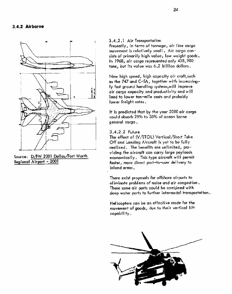
3.4.2 Airborne
3.4.2.1 Air TransportationPresently, in terms of tonnage, air line cargomovement is relatively small . Air cargo con-sists of primarily high value, low weight goods.In 1968, air cargo represented only 438, 900tons, but its value was 6.2 billion dollars.
New high speed, high capacity air craft, suchas the 747 and C-5A, together with increasing-ly fast ground handling systems, will improveair cargo capacity and productivity and willlead fo lower ton-mile costs and probablylower freig ht rates .
It is predicted that by the year 2000 air cargocould absorb 25/o to 35k of ocean borne
general cargo .
3.4.2,2 Future
The effect of V/STOL! Vertical/Short TakeOff and Landing Aircraft is yet to be Fullyrealized. The benefits are unlimited, pro-viding the aircraft can carry large payloadseconomically. This type aircraft will permitfaster, more direct port-to-user delivery toinland areas.
Source;
R ional Air rt � 2001
There exist proposals for offshore airports toeliminate problems of noise and air congestion .These same air ports could be combined withdeep water ports to further intermodal transportation.
Helicopters can be an effective mode for themovement of goods, due to their vertical liftcapability.

25
3.4.3 Waterborne
19801970 1990 2000
43,50025,500 33,500 50,00050 930 1 010 050
10 132117 127
4039
8 168 8 583 o43Ta nke rs Max DWT in
World Fleet 300,000 760,0001,4 o
1,000,000 1,000,0001,570Length feet! 1,135
Beam f eet 1
De th feet 9Draf t feet 72
1, 570252 2727
142 1 2129
1 o4 10Average DWTin World
F lect 39 825 76 225
185 000l,o4o
94 325
400,0001,325
90 000
317,0001, 230
Dry BulkCarriers
Max DWT in
World Fleet 105,000Length feet 70
183Beam feet! 125Depth feet! 71Draft feet
152 191099
7157Average DWTin World
Fleet 14,750 18,750 23,575 27,350
Projected Vessel Characteristics 1970-2000Source: V.S, Department of Transportation
Conta incr Max DWT inShips/General World FleetCargo Ships Len th feet
Beam f eet IDe th feetDra f t feet!Average DWTin WorldF lect
"Insof'ar as world pressures are concerned, theship appears to be coming first. The growingsizes of certain types of ships are increasinglyrendering many traditional ports obsolete interms of capabilities, and are forcing othersto adopt radically new handling, storage anddistribution techniques. In many cases, vastcargo volumes are involved which are alreadycausing the activities of superships to be con-centrated at new and often more remotelylocated deepwater, special ized harbors ."
Source: Harbor and Port Development, AProblem and an Opportunity. V.S. ArmyCorps of Engineers, Ju y 1968,
26
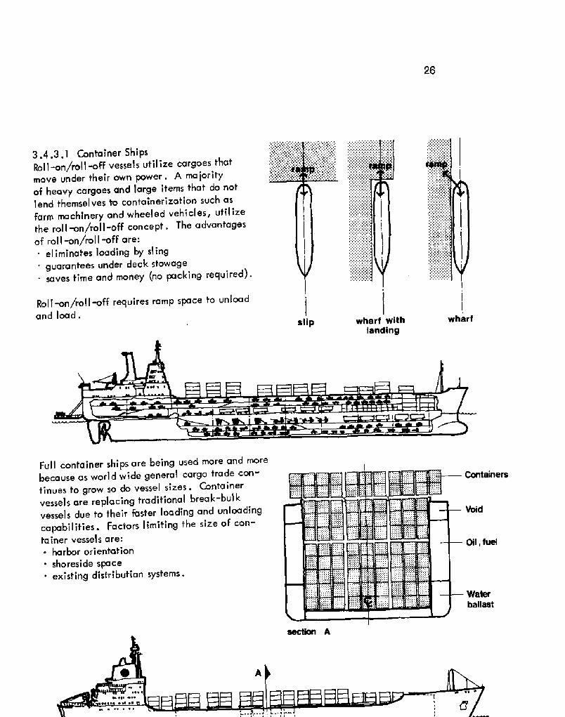
3.4,3.1 Container 5hipsRoll-on/roll -off vessels utilize cargoes thatmove under their own power. A majorityof heavy cargoes and large items that do notlend themselves to containerization such asfarm machinery and wheeled vehicles, utilizethe roll~n/roll-off concept. The advantagesof rol I -on/rol I off are:
eliminates loading by sl ing' guarantees under deck stowage
saves time and money no packing required!.
Roll-on/roll off requires ramp space to unloadand load.
slip wharfwharf with
landing
Full container ships are being used more and morebecause as world wide general cargo trade con-tinues to grow so do vessel sizes. Containervessels are replacing traditional break-bulkvessels due to their faster loading and unloadingcapabilities. Factors limiting the size of con-tainer vessels are:. harbor orientation
shoreside space' existing distribution systems.
Containers
Oil, fuel
Waterballast
27
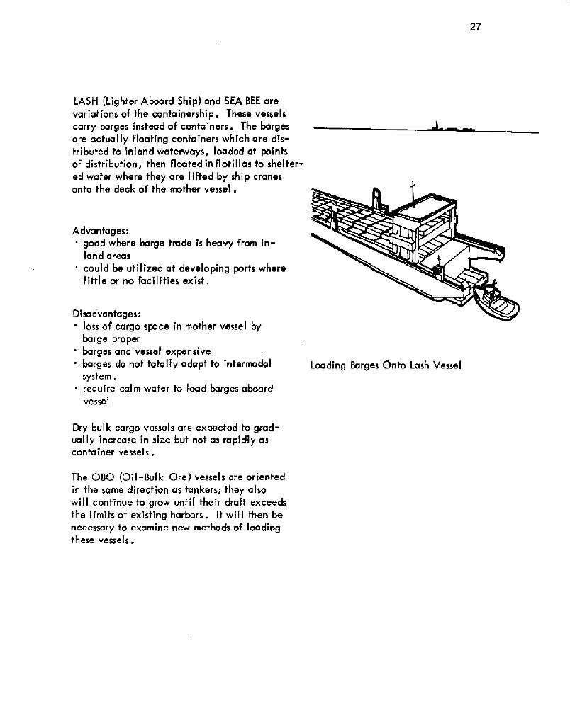
LASM Lighter Aboard Ship! and SEA BEE arevariations of the containership. These vesselscarry barges instead of containers. The bargesare actually floating containers which are dis-tributed to inland waferways, loaded at pointsof distribution, fhen floated in flotillas to shelter-ed water where they are lifted by ship cranesonto the deck of the mother vessel .
Advantages:' goad where barge trade is heavy from in-
land areas
' could be utilized at developing ports wherelittle ar no facilities exist.
Disadvantages:' loss of cargo space in mother vessel by
barge proper' barges and vessel expensive' barges do nof totally adapt to intermodal
system .require calm wafer to load barges aboardvessel
Dry bulk cargo vessels are expected fo grad-ually increase in size but not as rapidly ascontainer vessels.
The 080 Qil -Bulk-Ore! vessel s are orientedin the same direction as tankers; they alsowill confinue to grow until their draft exceedsthe limits of existing harbors. It will then benecessary to examine new methocls of loadingthese vessels.
Loading Barges Onto Lash Vessel

28
1945 17 000 dwt
%60 100000 dwt
1966 200 000 dwt
1NO 500000 dwt
Grawth in Tanker Size
3.4,3,2 TankersIn May 1969, 238 tankers, each in excessof 150,000 DW1', were under constructionor on order. 50 were in service at that timeand 6 of the 326,000 DWT tankers had alsobegun service. In addition to tankers, a146,000 DWT bulk salt carrier and a '157,000DWT ore-bulk-oil carrier were under construc-tion. Plans for a 215,000 DWT 080 wereunder consideration .
Tanker fleet now and proIectedSource: Port and Harbor Development, AProblem and An 0 rtunit
Tanker loading from floating offshore terminal
Incentive for vessel growth has beenstrongest for crude oil tankers. Increas-ing use of offshore terminals and newdeep water harbors located away fromtraditional established ports have con-tributed to this trend ~
Factors influencing tanker size:. sharp and continued increase in world
petrol eum demandincreased length of haul from sourcesof supply to refinery and consumptioncenters
comparative economics of tanker trans-porta t ion
' technological advances in large vesselconstruction .
Operational constraints of tankers:' serious handling problems in restricted
coastal and harbor waters' threat of oil pollution caused by vessel
casual it i es .
Future Concept - Submarine Tanker:Designed to bring oil from Arctic regionsunder the Artie ice-pack to ice free ports, thesetankers could be loaded from undersea termi-
nals while submerged, then unloaded at ice-fr ee ports by con vent iona I methods .

29
Area served by barge traffic from Port of New Orleans
Submarine Tanker proposed! loading fromunderwater terminal
Source: General Dynamics
3.4 .3 .3 8argesA barge is an unmanned vessel controlledby another vessel and generally with no load-ing or unloading equipment on board. Move-
~ ment of barges is usually done by tug boat.
Methods of barge movement

30
Deck Barge sizesinland offshore
Oil Bargesa ft. b ft.! c ft. ca acit barrels
Standard barge types
72 24 5
100 28 6.5
110 30 7120 30 7.3
139 32 7.5
150 34 10
170 40 10
180 50 10
205 40 10383 68 39.4
1, 2002,6003,0003, 2505,0006,0008,700
10,00011,400
120,000
Seagoing tank barge under tow
Load capacities of seagoing tank bargesrange from 25,000 barrels to 165,000barrels. Tank barges with 240,000 barrelscapacity for products suchas liquid causticsoda, benzol, toluene, aqua ammonia,ethylene glycol as we I I as petrol eum pro-ducts are in the planning stages.
The Alaska Hydro-Train, introduced in1963, provides a direct rail link betweenSeattle and Alaska. The concept is to usemarnrnoth ocean barges as rollmn/roll-offvessels capable of handling up to 64 loadedrail cars with various commodities.

Transocean Barges:The concepf is to develop transocean trans-portation systems with separable propulsionunits tugs and barges! to compete with systemswithout separable propulsion systems self-pro-peI'ted ships!. Ocean barging is o relativelynew mode of large-scale ocean transportafion,originating in the United States and Canada .
Transocean tug-barge system advantages oversel f-propel led vessels.~ manning
utilization
~ cargo-handling equipment~ operational flexibr I ity .
The major disadvanfage is that it is a lowspeed mode of transportation.
Transocean barge sizes
Conta incr Bu Brea BuCargo DWT 1,000 0,000, 0Length ff! 450 485 252Beam ft 85 105 55De th ft 32 35 18Draft ft 16 26 14
Proposed Transocean Container barge withcapacity of 910 twenty foof containersSource: Transocean Tug-Barge Sysfems
3.5 Cargo Handling 32
3.5.1 Method
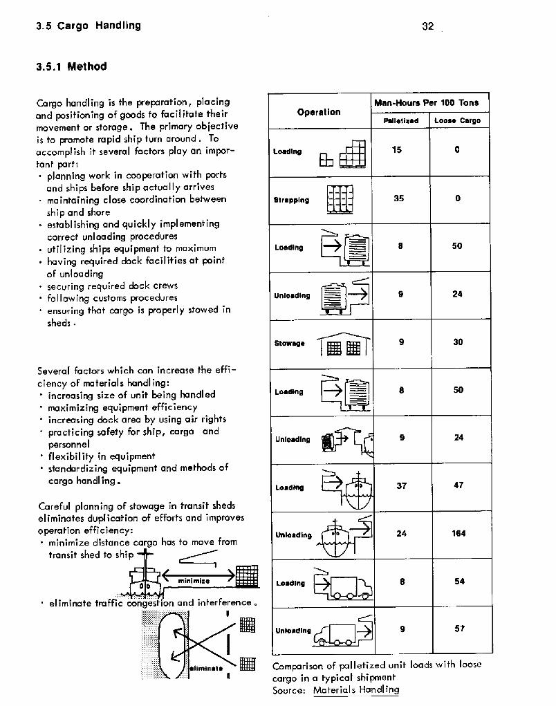
Cargo handling is the preparafion, placingand positioning of goods to facilitate theirmovement or storage. The primary objectiveis to promote rapid ship turn around. Toaccomplish it several factors play an impor-tanf parf:~ planning work in cooperation with ports
and ships before ship actually arrives~ maintaining close coordination between
ship and shore~ establishing and quickly impl emenf ing
correcf unloading procedures~ utilizing ships equipment to maximum~ having required dock facilities at point
of unloadingsecuring required dock crews
' following customs procedures' ensuring that cargo is properly stowed in
sheds.
Several factors which can increase the effi-ciency of materials handling:' increasing size of unit being handled' maximizing equipment efficiency
increasing dock area by using air rights' practicing safety for ship, cargo and
personnel' flexibility in equipment' standardizing equipment and methods of
cargo handling.
Careful planning of stowage in transit shedseliminates duplication of efforts and improvesoperation efficiency:~ minimize distance cargo has to move from
transit shed to sh
eliminate traffic congestion and inferference .
Comparison of pal letized unit loads with loosecargo in a typical shi pmen tSource: Material s Handling

33
Methods of Cargo Mandling by Cargo Types:A . Weavy and Large Bundles:' handled on the wharf by forklift or other
equipment with special attachments' readily loaded or discharged to vessels by
various slings' confine stowage to machine handling capa-
bil ities for optimum effi ci ency .
8. Unitized and Pre-Falletized Cargo:' normally handled by forklifts, paper roll
grabs, hydraulic clamping devices or otherattachments for liR trucks as required
' optimum speed attained by machine stowingcargo up to 8' high permitting easy tieringwith stability and eliminating the need fordunnage .
C . Loose Packages:' delivered loose by land transport to transit
shed' hand-loaded onto pallets � moved about shed
for storage or to ship on same pallets' unloaded by hand labor in the ships hold.
D. Containers:
~ small items or bulk materials are packed intolarger re-usable containers
' can be transported over land in same con-tainers as shipped
' large scale container operation requiresspecial equipment aboard ship or on wharfentry cranes, straddle trucks, etc.!
' promotes an economical transportationof cargoreduces pilferage, damage and laborhandling costs.
Stowage of modular units within a containerSource: Container Services of the Atlantic�1970
Route of typical container transport systemSource; Auckland Harbor Board, New ealand

3.5.2 Equipment
E . Rol I-on/Rol I off:This technique requires ships which have sideor end doors through which vehicles may bedriven. For maximum efficiency, a port needsto be equipped with moveable approach ram~,such as those used at ferry ships, which arecapable of adjusting to tides and ship sizes.
3.5.2.1 Ships GearA ma jority of ship loading is carried out byships gear because:' vessel can discharge goods when unable to
dock at berthsvessel capabilities are often greater than portca pabilities, especially in developingcountries
in case of shoreside power failuie, vessel canunload without being delayed.
Typical cargo vessels from the past are equippedwith a pair of cargo booms over each hatch.Ouring operation, one is positioned over theoffshore edge of the hatch, the other overhangingthe wharf. Cargo hooks hang from a link to whichboth hoisting lines are attached. By joint mani-pulation of two winches, the operator can dropthe hook into either side of the hold and maneuverthe load vertically or horizontally at high speeds,

35
a. Example of two swinging booms doubling upw i th a trave 1 ing bloc kb. Example of two swinging booms doubling upwith an equalizing beamSource: Marine Cargo Operations
New vessels are being constructed with shipcranes in adieu of conventional ships gearbecause:~ more effective
. manipulate loads over a greater area' decks are free of rigging' easier to operate
one crane will replace two pairs of cargobooms ~ Ship crane unloading lumber

36
3 .5 .2 . 2 Port Equipment
Wharfside cranes are used extensive'ly becauseof their large area of deposit. These cranes aregenerally mounted on tracks. Dock cranes aregrouped into three genera'l categories.
cantilever - mounted on roof of dock shedwith level luffing jib
~ semi~antry - one set of legs supported by arail along the face of a pier shed wall; hasrevolving capabilities
~ ful I arch gantry - a I I legs supported on wheel swith track mounted in apron; has revolvingca pa bil i ties,
The standard two wheeled hand trucks andfour wheeled platform trucks remain anessential tool in material handling, espec-ially in areas where labor is inexpensiveand the purchase of mechanized units is notwarranted. Soth are economical only onshort trips and are frequently used insideship hol ds.
Reproduced by permission of Cascade Corp.
Fork lifts have done more than any othersingle device to revolutionize cargo handlingon the wharf. They can pick up unit loads orpalletized loads off the apron, transfer themto transit shecls and stack them, 16 to 18 feethigh. Fork lifts are considered efficient forhorizontal movement up to 150 feet, Theyhave attachments enabling them to handlea multitude of special cargoes ~
Two examples of two wheeled hand trucks:a . Western styleb . Eastern styleSource: Marine Cargo 0 rations
37
Travel loader, or side carrier, is a combina-tion fork lift and straddle carrier. It has fheability to carry Iong lengths and very largeloads. It utilizes its own set of forks.
Overhead manorail sysfems keep the deckclear of moving vehicles. They have beenused successfully for many years, but pri-marily in specialized applicafians whereonly one commodify is continually handledover a short, fixed route .
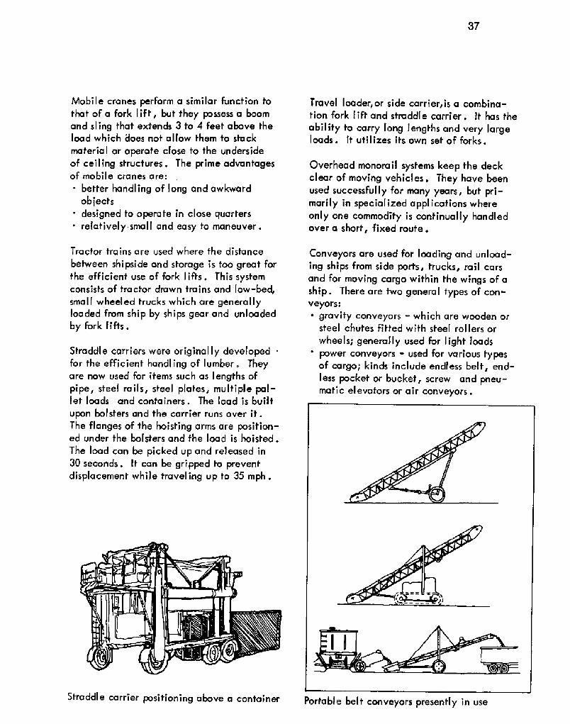
Straddle carrier positioning above a container Portable belt conveyars presently in use
Mobile cranes perform a similar function tothat of a fork lift, but they possess a boomand sling fhat extends 3 to 4 Feet above theload which does not allow them to stack
material or operate close to the undersideof ceiling structures . The prime advantagesof mobile cranes are:
better handling of Iong and awkwardobjects
' designed to operate in close quartersrelatively small and easy fo maneuver.
Tractor trains are used where the distance
between shipside and storage is too great forthe efficient use of fork lifts. This sysfernconsists of tractor drawn trains and low-bed,small wheeled trucks which are generallyloaded From ship by ships gear and unloadedby fork lifts.
Straddle carriers were originally developed .for the efficient handling of lumber. Theyare now used for items such as lengths ofpipe, steel rails, steel plates, multiple pal-let loads and containers. The load is built
upon bolsfers and the carrier runs over it.The flanges of the hoisting arms are position-ed under the bolsters and the load is hoisted.The load can be picked up and released in30 seconds. It can be gripped to preventdisplacement while traveling up to 35 mph.
Conveyors are used for loading and unload-ing ships from side ports, trucks, rail carsand for moving cargo within the wings of aship. There are two general types of con-veyors:
gravity conveyars - which are wooden orsteel chutes fitfed with steel rollers orwheels; generally used for light loadspower conveyors - used For various typesof cargo; kinds include endless belt, end-less pocket or bucket, screw and pneu-matic elevators or air conveyors.

38
3.5.2.3 Floating Equipment
Types of pal letsSource: Marine Cargo Operations
A floating pneumatic elevator used forloading and unloading barges and buik shipsSource: Materials Handling
Pallets are double platforms separated afew inches by batten strips to permit theinsertion of fork lift forks. The top plat-form supports the load and the bottom oneprovides a flat surface for stacking. Gen-erallyy pal lets are of woad construction.
Pneumatic or vacuum pumps are used inhandling bulk commodities such as oil andgrains, These are incorporated in grainelevators, oil tanks and floating grainelevators. The cargo is discharged fromthe ship by flexible pipes inserted intothe hold.
Pinwheel Brick

39
A tug boat's primary Iob is to meet ships atthe harbor entrance and guide them to theberth. Tugs push or pull f.he ship into a cor-rect course to speed up the docking proce-dure. The movement of barges and manyitems of floating equipment are provided bytug power . Generally tugs are privatelyowned and are contracted for service.
Floating drydocks can be used as gravingdocks. By flooding tanks which form partof its hull, if can be submerged to a sufficientdepth to allow ships to be floated into it.When the ship is in position the dock ispumped dry, leaving the ship sitting onblacks. Advantages of floating dry docks:~ do not require space on land~ can be relocated
~ can be altered to meet. increasing ships'I ze
' does not affect main stream of traffic,
Dredges are the means by which harborsand channels are deepened or maintained.
Examples of types of dredges;1. grab dredges2. cutter suction dredges3, cutler suction dredges4. trailing suction dredges.Source: Costain - Blankevoot Int'I .Dredging Co . Ltd .
Grab dredger at Port of New Orleans

40
Fire boats are used to combat fires aboard
ships and on piers, wharfs and water-front Facilities in support of land basedFire Fighting equipment.
3.6 Labor
3.6.1 Type
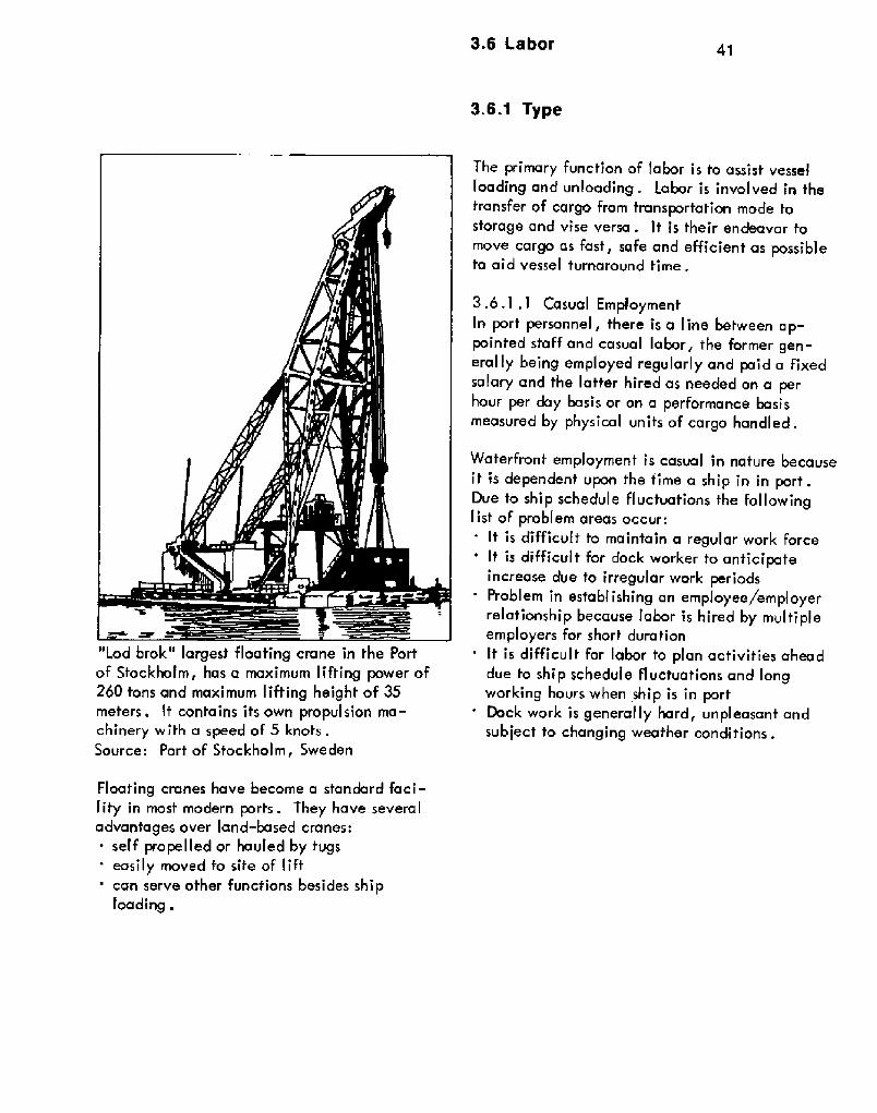
"Lod brok" largest floating crane in the Portof Stockholm, has a maximum lifting power of260 tons and maximum lifting height of 35meters. It contains ifs own propulsion ma-chinery with a speed of 5 knots .Source: Port of Sfockholm, Sweden
Floating cranes have become a standard faci-lity in most modern ports. They have severaladvantages over land-based cranes:~ self propelled or havled by tvgs
easily moved to sife of lift' can serve other functions besides ship
loading .
The primary function of labor is to assist vesselloading and unloading . Labor is involved in thetransfer of cargo from fransportation mode tostorage and vise versa . It is their endeavor tomove cargo as fast, safe and efficient as possiblefo aid vessel turnarovnd time.
3.6,1 .1 Casual EmploymentIn port personnel, fhere is a line between ap-pointed staff and casual labor, fhe former gen-erally being employed regularly and paid a fixedsalary and fhe latter hired as needed on a perhour per day basis or on a performance basismeasured by physical units of cargo handled.
Waterfront employment is casual in nature becauseit is dependent upon the time a ship in in port.Due to ship schedule fluctuations the followinglist of problem areas occur:
It is difficult fo maintain a regular work forceIt is difficult for dock worker to anttcipateincrease due to irregular work periodsProblem in esfablishing an employee/employerrelationship because labor is hired by multipleemployers for short durationlf is difficult for labor to plan acfivities aheaddue to ship schedule fluctuations and longworking hours when ship is in portDock work is generally hard, unpleasant andsubject to changing weather conditions,

42
tots Iportregistrst
70 POl'tquota
regulars
20
10
irregulars
Cl I
aCl
Z o
ClCl C
Cl
demand
supply of laborsupp l y of equipmentsupply of facilities
3.6.2 Structure / Organization
The port labor force is organized in a closedshop structure composed of registered dockworkers. A laborer generally wil I not be em-ployed unless he is registered with a local boardrun by the union. The union serves as an agentfor port labor. They obtain jobs from em-ployers stevedores! and distribute them amongthe membership. The union maintains andcontrols the size of the permanent registereddock worker supply.
The union negotiates contracts, sti pulatingbase rates of pay, overtime periods andnumerous working conditions, includinggrievances and disciplinary procedures. Theunion is charged with administration of sumsprovided by employers for labor welfareamenities as well as for minimal job train-ing programs.
Network used to get dock labor for a vessel
Cl Ia
o aE Z
0o
Comparison of 8 Australian ports �965! ofpercent of labor force; Also compares theregular vs. irregular percent of total regis-tered labor force
Source: Sea Gateway of Australia
43
3.6.4 Aie
5. 6o/o
17 Oo/
3. 6o/o
11. 2o/o1. 2/o
Proprietors padnagclerica I
3 3o/o professional andtechni ca I
semi-ski fled and
other manual
including regis-fered dock worke
73. P/o 84o/o
Nationa I
laborforce
Port
labor
force
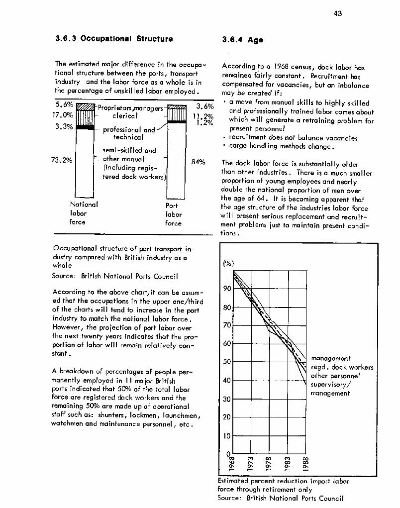
3.6. 3 Occupational Structure
The estimated major difference in the occupa"tionaI structure between the ports, transportindustry and the labor force as a whole is infhe percentage of unskilled labor employed.
Occupational strucfure of port transport in-dustry compared with British industry as awhol e
Source; British National Ports Council
According fo the above chart, it can be assum-ed that the occupations in the upper one/thirdof the charts will tend to increase in the portindustry fo match fhe national labor Force.Mowever, fhe projection oF port labor overthe next twenty years indicates that the pro-porfion of labor will remain relatively con-sfanf .
A breakdown uf percentages of people per-manently employed in 11 major Britishports indicated that 5O/o of the total laborforce are regisfered dock workers and theremaining 5 P/o are made up of operationalstaff such as: shunfers, Iockmen, launchmen,watchmen and maintenance personnel, etc .
According to a 1968 census, dock labor hasremained fairly constant. Recruitmenf hascompensafed for vacancies, but an inbalancemay be created if:~ a move from manual skills to highly skilled
and professionally trained labor comes aboutwhich wilt generate a retraining problem forprese n t personn e I
- recruitment does nof balance vacanciescargo handling methods change.
The dock labor force is substantially olderthan other industries. There is a much smallerproportion of young employees and nearlydouble the national proportion of men overthe age of 64. It is becoming apparent thatfhe age structure of the industries labor forcewiII present serious replacemenf and recruit-ment problems just to maintain present condi-tions.
Estimated percent reduction import laborforce fhrough retiremenf onlySource: British National Ports Council

44
3.8.5 Mechanization
A comparison of age structureSource: British National Ports Council From the above chart two conclusions can bedel ermined:
' when bulk cargo is handled by labor, the dockworkers are responsible for only 5 P%%d of theturn around rate of vessels in a port; the other50%%d can usualIy be attributed to waiting onfacil ities
' when labor is engaged in handling non-bulkcargo the workers are almost solely responsi-ble for the turn around rate of vessels in port.
Estimated reduction in British dock labor force
assuming no recruitment
45
3.6.6 Safety
1/0Ton/ho rCost/h our
Cost/Ton
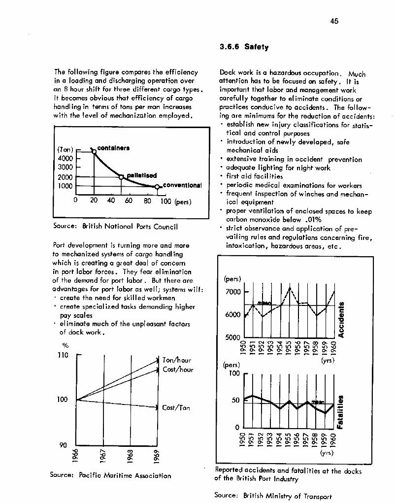
The following figure compares the efficiencyin a loading and discharging operation overan 8 hour shift for three different cargo types.It becomes obvious that efficiency of cargohandling in terms of tons per man increaseswith the Ievel of mechanization employed.
Source: British National Ports Council
Port development is turning more and moreto mechanized systems of cargo handlingwhich is creating a great deal of concernin port labor forces. They fear eliminationof the demand for port labor. But there areadvantages for port tabor as well; systems will:' create the need for skilled workmen
' create speciaHzed tasks demanding higherpay scaleseliminate much of the unpleasant factorsof dock work.
Source: Pacific Maritime Association
Dock work is a hazardous occupation.attention has fo be focused on safety. It isimportant that labor and management workcarefully together to eliminate conditions orpractices conducive to accidents. The follow-ing are minimums for the reduction of accidents:
establish new injury classifications for statis-tical and control purposesintroduction of newly developed, safemechanical aids
' extensive training in accident preventionadequate lighting for night workfirst aid facilities
periodic medical examinations for workersfrequent inspection of winches and mechan-ical equipmentproper ventilation of enclosed spaces to keepcarbon monoxide below .019o
' strict observance and application of pre-vailing rules and regulations concerning fire,intoxication, hazardous areas, etc .
Reported accidents and fatalities at the docksof the British Port Industry
Source; British Ministry of Transport

46
3.6.8 Wages3.6.7 Work Hours
Advantages:more money for labor.
The regular work hours during which basic payis earned are generally fixed, 8uf it is oftendifficult to match ship discharge and loadingoperations to regular working shifts. ln orderto accomplish prompt dispatch of ships andmaximize shore efforts, work beyond normalhours is often required.
3.6.7.1 OvertimeThis is the most common method for extendingnormal working hours. Disadvantages ofovertime:
' physical exhaustion of labor force due tolong and hard hours
' reduced output of tired labor increasescost per ton of cargo handled
' accident potential increases
3.6.7,2 ShiftThis is an incentive method for ports thatpermits higher utilization of port facilities,reduces the need for capital expenditures,and facilitates more rapid turnover of ships.
Disadvantages of shift method:. requires increase in the number of register-
ed dock workers which creates an unecono-
mical increase in pensionable stafFshifts conflict with maintenance and repairwork of port equipment which is generallycarried on during non-working hours.
The wages paid to the dock worker are usuallypaid upon either an hourly basis or on piecerate,' paid per ton, sack, bale or other unit ofmeasurement. The hourly system is usuallybased upon an agreed hour related to the work-ing unit. Three rates apply depending on timein vol ved:~ standard time regular rate!
overtime usually 5 P!o higher than standardtime!double time double standard time rate!.
Piece rates are generally most useful in stimu-lating output when applied to a consistentvolume of standardized cargo. To achieve themost effective use of the unit rate, it must beclassified according to the following conditions:~ weight~ stowage conditions
handl ing procedurescondition of cargo hazardous, sticky, cracked! .

3.6.9 Amenities and Welfare 3.6.10 Manpower
In but a few ports do adequate amenitiesfor dock labor exist. The facilities pro-vided should include:
. sanitary accommodations
. washing facilities and changing roomseating Facilitiesfirst aid facilities .
Labor does not qualify for the Financialsecurity measures provided by the portauthorities for appointed staff, however,the labor unions have undertaken to com-
pensate ~embers by providing Fringe bene-fif' payments. In recent years, pensionplans have been introduced together withplanned compulsory retirement .
Many schemes and plans have been initiatedin an attempt to solve labor problems, enhancedock worker status and increase the efficiencyof dock labor. Decasualization is a schemewith many favorable merits:
reduction of fluctuation of employment byreducing the number of labor contractors
' increase security of employment by pro-viding a steady income levelincrease the efficiency of employees
. provicfe a way to control the number ofemployees in a port.

48
3.6.11 Training
process .
The objective of a training program is to esta-blish a permanent, qualified labor force capa-ble of handling multiple situations. This isachieved by:
understanding mechanization proceduresstimulating pride in workmanshi p
' promoting safety and team workintroducing an apprentice program with suf-ficient salary to recruit young! traineeworkers
establishing performance criteria to evaluateworkers.
Existing training programs have two levels:basic and advanced. The basic training programis composed of practica'1 and theoretical sessionsinvolving familiarization with the harbor, withprocedures in the arrival and departure of vessels,w]th ship layout, the nature of port business,cargo gear, machinery, safety, first aid andwith hygiene. Practical instructions are givenin lifting, hoisting, tallying, shed and cargowark, stowage and dunnaging of goods invessels, driving fork lifts and handling of bulkcargoes. This program is offered to selectedstaff and employees involved in:
loading and unloading which requires theknowledge of the operation of not on] ymechanical lifts but transport equipmentas well
~ supervision so they can understand how toread ship stowage plans and cargo place-ment in transit sheds and warehouses, propertal]ying and record keeping, as well as organi-zing labor gangs
~ crews involved in maintenance of portequipment, structures and facilities.
Advanced training is offered for tally men andweighers to qualify them for certification as aweigher and measurer. Advanced training maybe offered to supervisors and checkers. Thislevel is primarily theoretical designed forthe general education level of the trainees.
Some ports have attempted to introduce teenagestudents into apprenticeship programs wherethey receive part-time instruction, generaleducation, on a partly paid basis.
Problems connected with training programs:~ recruitment of qualified instructors' provision of adequate training faci]ities
attitude of older workers towards education
A suggested pattern for manpower planningSource: 8ritish National Ports Council

3.7 Support Industry 49
Supporting industries are natural productsof porfs. They use fhe raw maferials accessibleat a port and utilize the transportation modesfor distribution of their products. Many in-dustries need waterfront locations because of:
availability of barge serviceconsiderable amounts of water
' waste disposalimported raw materials
' close proximify to primary economicaltransportafion for foreign markets.
Industry is selected For location at a portbased on "desirability criteria":
environmental capability' employment density' demonstrated growth, locally and
nafional lypotential for generating port cargo.
Criteria for industry fo locate at ports are:proximity to local and export marketsavailability of labor
' availabilify of ship, rail, barge andtruck transportationproximity to production materials
' availability of low cosf utilifies water,power and fuel!
' availability of special port services.
The following selected examples indicate thewide cross section of supporting industries afa typical port:
4 . Genera I Industry:sugar refinery
' pulp and paper millcorrugated shipping container plant
. methanol plantbutyl rubber plant
~ mixed fertilizer planf' plastic products plant
flat glass plant' portland cement plant
clay soil pipe plant
abrasives plant - mineral wool insulation plantbasic oxygen steel plant and hot rolling millsteel pipe plantaluminum reduction plantaluminum rolling and drawing millmetal cans plant, hardware plantvalves and pipefittings plant, metal sfampingsplantmarine.and traction diesel engine planttractor and farm equipment plantoilfield machinery and equipment plantbulldozer and crane plantpump and compressor plant, refrigeration andair conditioning plantelectrical motor and generator plantelectrical control s planftruck and bus bodies planttruck trailors plankshipyard, boat building and repair plantrailroad car planttrailer coach plant,
B. Marine Related Industry:boats, amphibious vehiclesmarine and land geophysicat survey
' oceanic instrumentation manufacturers
' tug and barge transportdrilling rigs and associated equipment manu-facturer
marine constr uct ion
ship brokers and charteringelectronic equipment fabricators and manu"facturers
fishingtourist and recreation
develop and manufacture heavy duty main-fenance coatingschemical recovery from seawaferpipe manufacturershi p buil dingdiving and sal vageship repairoyster shel Iconcrete manufacture
sales and service oF marine craft
engineering, manufacturing, equipment andvehicles .

3.8 Safety 50
3.8.1 Types of Fires
3.8.1.'i Class AFires in ordinary combustible materials such asmattresses, dunnage, piles of wood and shav-ings, canvas, etc. These fires are best ex-tinguished by the quenching and cooling effectsof quantities of wafer or water fog .
3,8.1.2 Class BFires in substances like gasoline, oil, dieseloil, lubricating oil, tar, grease, etc. Thistype of fire requires a blanketing or smother-ing effect produced by an extinguishing agent.
3.8.1.3 Class CFires in live electrical equipment such asswitch board insulation, transformer terminalsretc. The extinguishing agent must be non-conductive to eliminate the hazard of electricalshock to the fire fighter.
3.8.1 4 Class DFires in combustible metals such as-magnesium,sodium, titanium, lithium, etc.
3.8.2 Firefighting Agents
3.8.2.1 Fire Main SystemThe Fire main system aboard a vessel is asystem of permanent piping which receiveswater pumped from the sea and delivers itto fire hydrants strategically located through-out the ship.
Fire hydrant � outside station
3.8.2.2 WaterWater as a cooling agent is the most commonmethod of fighting fires. Generally water issuperior to other agents and is usually avail-able in ample quantities at low cost. Water,in the form of 6g, has the greatest capacityfor heat absorption of all the extinguishingagents presently in use. Fog also has the capa-bility to dilute combustible vapors as the fogturns to steam by the heat of the fire. lt alsoforces air away from the fire, thereby removingthe oxygen needed to support combustion.
3.8.2,3 FoamFoam is an effective agent for Class B fires andsome Class A fires. Foam has a few disadvan-
tages, namely: it conducts electricity, it's notalways effective on Rowing liquids and it's noteffective at extremely low temperatures under10 F.!.

51
Operation of mechanical foam pickup unit
Foam For fire-extinguishing pur poses onboardtank vessels is of two types: chemical andmechanical. The characteristic difference isin the equipment for producing the Foam. Thenozzel used for mechanical Foam adds air tothe chemical bearing sfream ofter the chemi-cals have been dissolved in if, whereas thenozzle for chemical foam does not add air.
3.8.2.4 Carbon Dioxide CO2!This agent is an excellenf smothering agentfor exfinguishing Class 8 and C fires in lo-cations where it can nof be widely diffusedor, if the Fire is beyond the incipienf stage,where it is not blown away by drafts. Carbondioxide is most effecfive when applied in anarea where it will remain as a cover langenough to reduce the oxygen level below thepoint of combustion. Caution � if oxygen ismade available to fires extinguished by CO2it is possible to rekindle them. !
3.8.2.5 SteamThe steam smothering system is one of the oldesttypes oF fire-fighting methods used aboard tankvessels. Its primary purpose is to smother firesin enclosed or confined spaces. Steam alsocools the fire and dilutes vaporm ir mixtures toa point below combustion. This system is notinstalled on vessels constructed today.
3.8.2.6 Dry ChemicalDry chemical extinguishers are effective onall Class B and C fires. On Class C fires,fheresidue, a powder, renders electrical contactsand relays inoperative which is a minor dis-advantage. However, there are several ad-vantages the dry chemical has over CO2:~ greater range
stream provides excellent shield for thefire-fighter .
"30 pound" dry chemical extinguisher sectiona I view!
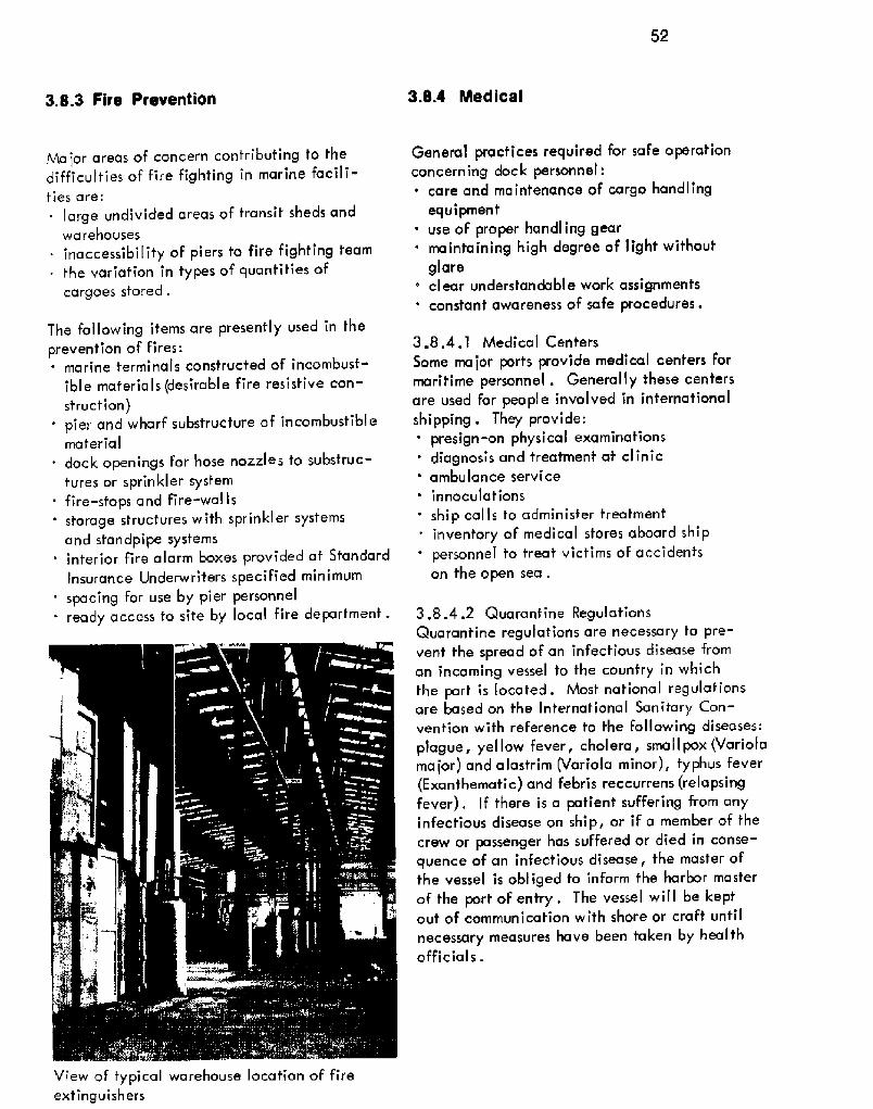
52
3.8.3 Fire Prevention 3.8.4 Medical
Ma jor areas of concern contributing to thedifficulties of fire fighting in marine facili-ties are:
large undivided areas of transit sheds andwarehousesinaccessibility of piers to fire fighting team
~ the variafion in types of quantities ofcargoes stored.
The following items are presently used in theprevention oF fires:
marine terminals constructed of incombust-ible materials desirable fire resistive con-struction!
' pier and wharf substructure of incombustiblematerialdock openings for hose nozzles to substruc-tures or sprinkler systemfire-st'ops and Fire-walls
' storage structures with sprinkler systemsand standpipe systems
' interior fire alarm boxes provided af StandardInsurance Underwriters specified minimum
' spacing for use by pier personnel. ready access to site by local fire department.
View of typical warehouse location of fireextinguishers
Genera'I practices required for safe operationconcerning dock personnel:~ care and maintenance of cargo handling
equipmentuse of proper handling gear
' maintaining high degree of light withoutglare
' clear understandab! e work assignments' constant awareness of safe procedures.
3.8.4,1 Medical CentersSome major ports provide medical centers formaritime personnel . Generally these centersare used for people involved in internationalshipping . They provide:' presign-on physical examinations
diagnosis and treatment at clinic' ambulance service
innocul at ion sship calls to administer treatmentinventory of medical stores aboard shippersonnel to treat victims of accidentson the open sea .
3.8.4.2 Quarantine RegulationsQuarantine regulations are necessary to pre-vent the spread of an infectious disease froman incoming vessel to the country in whichthe port is located. Most national regulationsare based on the International Sanitary Con-vention with reference to the following diseases:plague, yel low fever, cholera, sma1 I pox Variolama jor! and alastrirn Variola minor!, fyphus fever Exanthematic! and febris reccurrens relapsingfever!. If there is a patient suffering from anyinfectious disease on ship, or if a member of fhecrew or passenger has suffered or died in conse-quence of an infectious disease, the master offhe vessel is obliged to inform fhe harbor masterof the port of entry. The vessel will be keptout of communication with shore or craft untilnecessary measures have been taken by healthofficial s .

53
Spherical BuoyNun Buoy Can Buoy
3.8.5 Navigation Alcts
Navigation aids function to warn vesselsof hidden dangers and to provide directionin safe waters. The types of aids vary withthe waterways ond the functions they serve.
There are two basic types of navigationalaids, floating and fixed, which include..' floating buoys' fixed structure channel markers
' navigational lights on piers, wharvesand dol phins
' fixed-structure light beacons on shoreand breakwaters
' lighthouseslight ships
' range I ight installations on framed struc-tures on shore.
l.ighted Buoy Spar Buoy Lighted Buoy withRadar Reflector
Selected buoy typesSource: Design and Construction of Portsand Marine Structures
Fixed structure channel markers possess:~ lights. anchored to bottom
' radar reflectors.
Fixed-structure beacon lights are located onprojecting ends of breakwaters and on the salientpoints of land projecting into the navigationaIwaters at harbor entrances.
Lighthouses are tower structures fixed! withmarine beacons lights, fog signals, sound de-vices and radio stations. They are locatedon points along the shore to guide vesselssafely to port and require durable structure towithstand heavy wave action . Lighthousesrequire long visibility to be effective.
Light ships serve the same Functions as lighthouses and may be manned or unmanned.
Radar light installations are used to guicteshi pping through hazardous, narrow ortwisting port entrances and channels. Thestructure is generally a metal frame witha unidirectional marine range light lanternon top. They are powered by shore electricity.Critical factors include the distance betweenlights, the height of the lights and thecandl e-I ight sensitivity of the I ight .
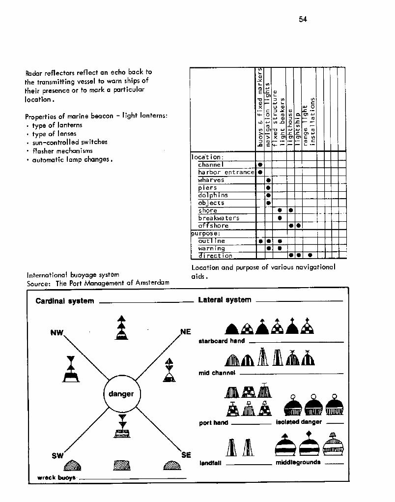
54
Radar reflectors reflect an echo back tothe transmitting vessel to warn ships oftheir presence or to mark a particularlocation .
Properties of marine beacon � light lanterns:~ type of lanterns~ type of lenses~ sun-controlled switches' flasher mechanisms~ automatic lamp changes.
International buoyage systemSource: The Port Management of Amsterdam
Location and purpose of various navigationala I cls .

3.9 Finance 55
3.9.1 Objectives3.8.6 Marine Safety
Some oF the worst ship accidents have oc-curred in harbors or inland waterways. Thecauses have been attributed to poor vesseldesign, improper maintenance, over-load-ing, poor navigation, weather and badjudgement on the part oF the ships officers.The majority of these, after careful analysis,were found to have been preventable.
The Coast Guard is concerned with merchant
marine safety, aids to navigation, searchand rescue.
The Merchant Marine inspection office hasthe task of inspecting ship construction andstructural alterations from the drawing boardto actual launching . They also inspect cargohandling equipment, life boats and othersafety equipment aboard ship.
The captain oF a port's own vessel is chargedwith the responsibility oF inspecting vesselsand waterfront facilities for proper stowageof dangerous cargo. His personnel providesupervision of fhe loading of explosives andradioactive materials. They then provideescort away from the port proper.
Port warehouse fire
Reproduced by permission of U.S. Coast Guard
Ports usually do not have any direct stimulusother than their financial performance andtherefore must establish goals in financialterms. They must take into account statutoryobligations and other special circumstancesappropriated to the individual port.
The Rochdale Committee oF England establish-ed several financial objectives that a portshould attempt to achieve:~ depreciation at replacement cost' working expenses
interest on loans' taxation
a reserve to meet contingencies to assistin financing minor improvements.
If financiaJ objectives are not met then pro-blems arise for ports such as.
insufFicient resources available to modern-ize and develop as required
' cannot combat trade pattern Fluctuations' cannot offset high cost ot' labor with the
economics of mechanization
' replacement costs exceed original costsand differences have not been properlypre pa red for
' new loans at higher interest replace oldloans at much lower interest ratespremature obsolescence of port facilitiesbrought about by advanced ship and trans-portation technology.

3.9.2 Revenue
3,9.2,1 ChargesCharges are designed to insure enough revenueto meet the financial objectives of the port.They should be based on the need of a portwith respect to the particular services the portprovides.
A difficult problem in determining a standardcharge structure based on cost, arises from thevariations of unit costs at different cost centersoffering similar facilities to users. The fol-lowing chart indicates the percentage varia-tion in the charge level of major English ports.
Source: British Ministry of Transport
ln assessing charges in a new facility whichis in the building up stage of its developmentand has not established itself, it would be pro-hibitive to calculate charges based on actualcosts. In this case, charges are usually basedon estimate'd average cost. This type of chargerequires a continual review in order to avoidundercharging .
Port operating revenues are generally derivedfrom:
~ charges against vessels~ charges against cargo. rental of space within port limits~ passenger dues where applicable
' charges for handling~ charges for other services and facilities.
Dues on vessels consist of harbor dues, sovereign-ty, and stay within the port area, as well asdockage charges wharf, buoys, anchorage!,pilotage, towage, mooring, line handling,etc. Dues are charged to a ship owner on thebasis of the net registered tonnage of the shipwith respect to these variables:
nature of voyage' reason for anchorage storm, repair, etc.!.
Dues on goods are more commonly referred toas port rates, dock rates, wharfage rates, quayrates, etc. They are levied on all goods ship-ped or received at port and are chargeable basedon unit weight, volume or number. Dues arepaid to the port authority.
To apportion charges between vessel and cargois a difficult task. In practice, charges areusually based upon one or the other, separately .Vessel charge:~ waterway and berthing areas~ 5 Pk of open wharFs and included land
aprons
' all of land supporting aprons and 5 F/o of landsupporting aprons with tracksaisle space within the shed used by vessel orits agents in receiving cargo or de! ivering it toa point of storage, together with a proportionateshare of the supporting landservices covered by "Service Charge"office and other space used by vessels clericalForces .
Cargo charges:all land not previously covered
' all trackage and its supporting structure' 50% of open wharfs' aisle space not covered in vessel charge
all cargo areas within shedsall other trackage, roadway, etc.any services rendered for the benefit of cargo.
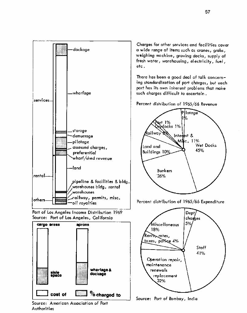
Charges for other services and Facilities covera wide range of items such as cranes, grabs,weighing rnachine, graving docks, supply offresh wafer, warehousing, electricity, fuel,etc .
There has been a good deal of talk concern-ing standardization of port charges, but eachport has its own inherent problems that makesuch charges difficult to ascertain.
Percent distribution of 1965/66 Revenue
Percent distribution of 196'/65 Expenditure
Port of Los Angeles Income Distribution 1969Source: Port of Los Angeles, California
Source: Port of 8ombay, IndiaSource: American Association of PortAuthorities

g plannin9 58

59
4.1.1 Decision 4.1.2 Preliminary
Decision Matrix
4.1 Design and Construction
Factors affecting the decision to build a port:
4.1.1.1 Need and Economic Justification
to serve a growing inland metropolis' to serve as a shipping terminal for private
industry' to serve as a military terminal or naval
base .
A private port will have to show economicfeasibility whereas a municipal or militaryport will tend to grow out of necessity.
4.1.! .2 Traffic Volume
A survey of anticipated future commerce type and quantity! will be required for muni-cipal ports. A private port must have a guar-anteed tonnage.
4.1.1.3 Inland CommunicationThe inland transportation routes require studyto determine feasible locations for road, rail,water and airways to service the port .
After establishing the general requirementsfor a port it is necessary to make a preliminarysite study supplemented with cost estimatebased on assumptions that will require verifi-cation in the final analysis.
4.1 .2.1 Prel iminary Site InformationInformation From several proposed sites fo becompared will be derived from:Marine Data:
depth of watergeneral character of bottomrange of tides and current
Met coro i og i ca I Da ta:w ind
tern pera turera infa I I
Topographical Data:~ shoals~ reefs
~ mouths of rivers~ shore I ine
Geographical Information:~ depth and presence of rock~ depth of overburden~ soils.
4.1.2.2 Selection Criteria
The following factors will play an importantrole in the final selection:
' amount of dredging minimize!' most favorable bottom conditions
' most suitable shore area for terminal develop-ment
transportation accessibilitydevelopment future of areadepth of waterexposure of coast
' orientation.
In areas where tide is 2 to 3 feet, the adjacentland area should be approximately 15 to 20 feethigher. If tides are higher or the area is subjectto tidal waves, then even higher elevation isdesirable. River locations where flood conditions
exist may require higher elevation also.
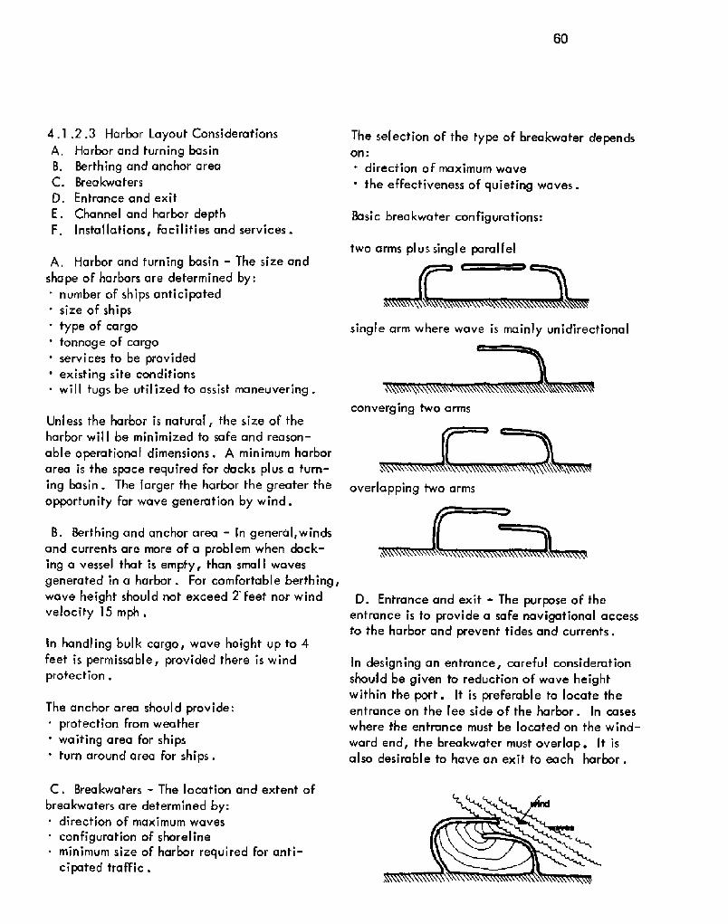
60
converging two arms
overlapping twa arms
4.1 .2.3 Harbor Layout ConsiderationsA. Harbor and turning bas in8. Berthing and anchor areaC. Breakwaters
D, Entrance and exit
E. Channel and harbor depthF. Installations, facilities and services.
A, Harbor and turning basin - The size andshape of harbors are determined by:' number of ships anticipated' size of ships
type of cargo' tonnage of cargo
services fo be provided' existing site conditions
wiII tugs be utilized to assist maneuvering .
Unless the harbor is natural, fhe size of theharbor will be minimized to safe and reason-
able operational dimensions. A minimum harborarea is the space required for dacks plus a turn-ing basin. The larger fhe harbor the greater theopportunity for wave generation by wind.
B. Berthing and anchor area � ln general, windsand currents are more of a problem when dock-ing a vessel that is empfy, than small wavesgenerated in a harbor. For comfortable berthing,wave height should not exceed 2' feet nor windvelocity 15 mph.
In handling bulk cargo, wave height up to 4feet is permissable, provided there is windprotection .
The anchor area should provide:prot ection from wea the r
' waiting area for ships' turn around area for ships.
C. Breakwafers � The location and extent ofbreakwaters are determined by:
direction of maximum waves
configurafion of shorelineminimum size of harbor required for anti-cipated traffic .
The selection of the type of breakwater dependson:
direction of maximum wave
' the eFfectiveness of quieting waves.
Basic breakwater configurations:
two arms plus single parallel
single arm where wave is mainly unidirecfional
D. Entrance and exif - The purpose of theentrance is to provide a safe navigational accessto the harbor and prevenf tides and currents.
In designing an entrance, careful considerationshould be given to reduction of wave heightwithin the port. It is preferable to locate theentrance on the lee side of the harbor. In caseswhere the entrance must be located on the wind-
ward end, the breakwafer must overlap. It isalso desirable to have an exit to each harbor.

61
The Stevenson equation computes the heightof a reduced wave at any poinf in the harboras a result of the enfrance. All dimensionsare in feet.
bqp-H � -a.m D s+ � !B B
hp = height of reduced wave at any pointin the harbor
H = height of wave at the entranceb = breacfth of entranceB = breadth of harbor at point pD = distance from entrance to point of
observation
The fype of entrance depends upon:' depfh of water' size of harbor
' ship characteristics ~
Three basic harbor entrance sizes are:' small harbor entrance � 300 feet' medium harbor enhance � 400-500 feet
' large harbor entrance - 500-800 feet.
E. Channel and harbor depth � These depthsshould permit navigation at low tide when aship is fully loaded. Surge of a ship is cal-culated af one half maximum wave height.!
Depth Iacfors:. botfom conditions
the maximum wave height.
When waves in a harbor do not exceed 2 feet,a depth of surge plus 4 feet is required for asoft bottom. For a hard bottom, a surge plus
6 feet is required. In areas where ships ar-rive empty and leave loaded,two depths ofchannel could be provided.
In the past, the loaded draft of ships has beenlimited to not over 40 feet so as nof to exceedthe principal harbor and channel depths of themajor world ports. The current trend in deepdraft vessels is presenfly being handled by:' use of submarine lines with offshore anchor-
age in deep water' lightening by transferring part of the load
to another vessel then finishing loading indeep wafer
' construction of special deep water terminals.
F. Installations, Iacllities and services-' shore facilities for marine terminals~ docks - The number of docks vary according
to fhe anticipated number of vessels, loadingtime involved and cargo types.
The Elements that determine dock types are:' special requirements or local customs and
practicessite conditions
availability of materialspermanency of construction
. economy of construction' size and weight of ships using port
method of construction time factor!.
Dredging may not be done until docks are built.Wharfs and piers should be located in the mostsheltered part of the harbor and along the leeside of the breakwaters.
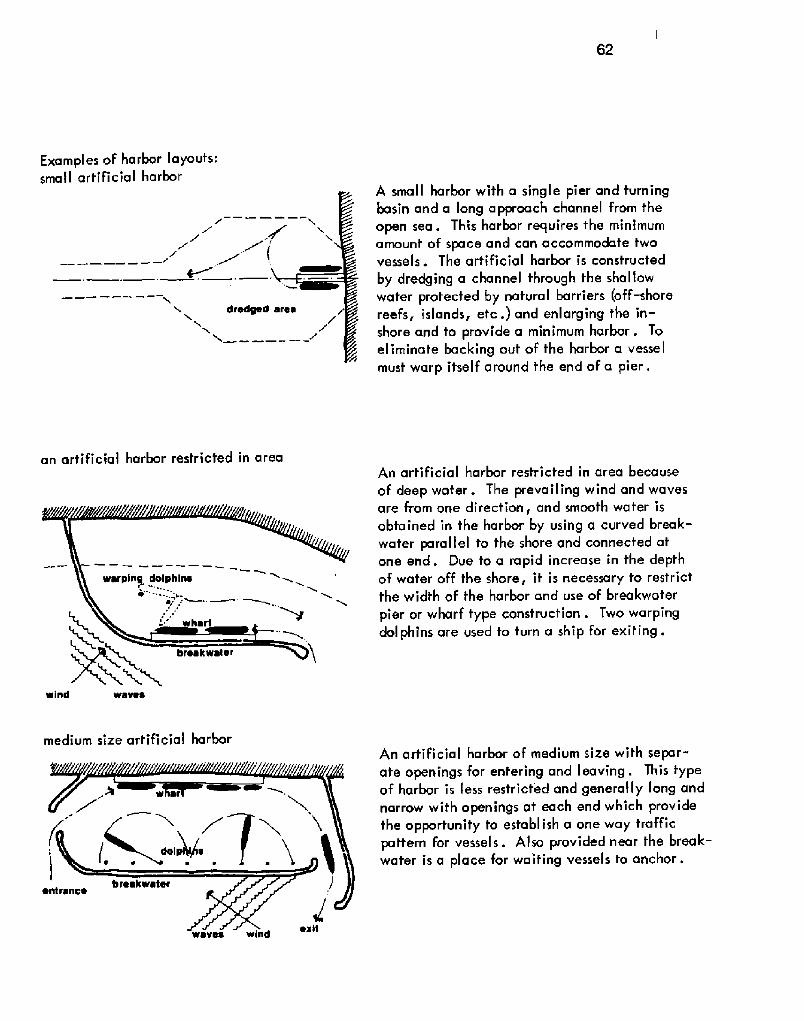
62
dredged
wind waves
waves win
Examples of harbor layouts:sma l I artificial harbor
an artificial harbor restricted in area
medium size artificial harbor
A small harbor with a single pier and turningbasin and a long approach channel from theopen sea. This harbor requires the minimumamount of space and can accommodate twovessels. The artificial harbor is constructedby dredging a channel through the shallowwater protected by natural barriers off-shorereefs, islands, etc.! and enlarging the in-shore and to provide a minimum harbor. Toeliminate backing out of the harbor a vesselmust warp itself around the end of a pier.
An artificial harbor restricted in area becauseof deep water. The prevailing wind and wavesare from one direction, and smooth water isobta ined in the harbor by using a curved break-water parallel to the shore and connected atone end. Due to a rapid increase in the depthof water off the shore, it is necessary to restrictthe width of the harbor and use of breakwaterpier or wharf type construction. Two warpingdolphins are used to turn a ship for exiting.
An artificial harbor of medium size with separ-ate openings for entering and leaving. This typeof harbor is less restrict'ed and generally long andnarrow with openings at each end which providethe opportunity to establish a one way trafficpattern for vessels. Also provided near the break-water is a place for waiting vessels to anchor.

63
medium size artificial harbor with turningbasin
wavea windA medium size artificial harbor with a fullturning basin, protected by fwo breakwaterarms. The radius of the turning basin istwice the length of the largest anticipatedvessel . this is the smallest radius a shipcan comfortably turn on, under continuousheadway without the assistance of a tug.!
large artificial harborA very large artificial harbor with anch-orage area, several berths, turning basinand several service Facilities.
bra
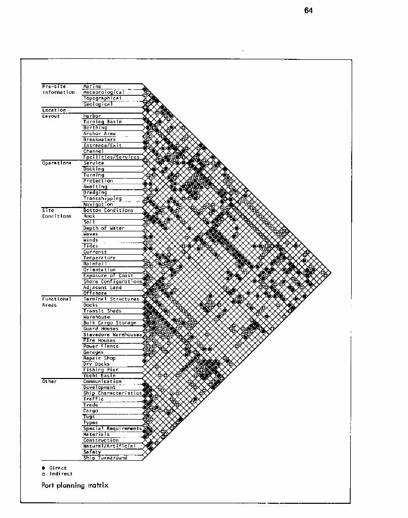
Pre-s teI nf orma t i on
MarineMetearola ica'ITopographicalGeo o ica
LocationHa rborTurnin Bas in
Layout
Bert inAnchor AreaBreakwate.rsEntrance/ExitCha nne IFacl I it ies/Services
Operations ServiceDockinTurningProtectionAwaitinDred inTranss I 'InNevi ationBottom ConditionsSite
Conditions Roc kSoiDe th of WaterWavesWindsTidesCurrentsTem eratureRa infa I IOr i enta t i onEx osure of CoastShare Conf i urat ionsAd ' scent La ndO s hareTerminal StructuresFunctional
Areas Doc ksTrans i t ShedsWarehouseBu 1 k Ca r o Stora eGuard HousesStevedore WarehousesFire HousesPawer P lantsGare esRe ir ShoDry DocksFishin PierYacht Basin
Other Communication~0tShi Characterist icsTraff icTradeCa rgoTu sTy esSpecia 1 RequirementsMateria sConstructionHa t u ra I /A r t 'I f I c il a ISa etShi Turna round
~ Directci Indirect
Port planning matrix
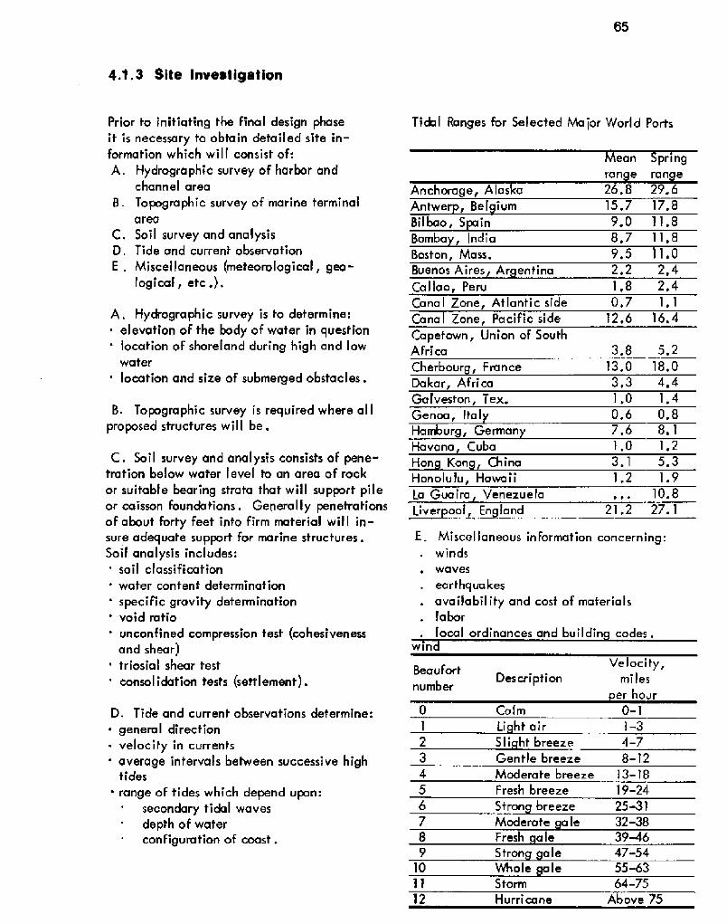
65
can pring
ran e ran e
26. 8 29. 6
15.7 17.8Anchorage, Alas aAntwer Bel ium
Bilbao, S inBomba, IndiaBoston, Mass,
9.0 11.8
8.7 11. 8
9.5 1.0
2,2 2,41,8 2,40,7 1,1
12.6 16. 4
3.8 5.2
13.0 18.0
3,3 4,4Cherbourg, FranceDakar, AfricaGalveston, Tex.Genoa, ItalHamburg, GermanHavana, Cuba
1.0 1. 4
0.6 0.87.6 8. 1
I.O 1,2
Hon Kon China 3.1 5.3
Honolulu, HawaiiLa Guaira Venezuela
1.2 1.9
10. 8
Liver ool, England 21.2 27. 1
win
Ve loci ty,mi les
er hour
Beaufort
numberDescription
4.1.3 Site Inveatigation
Prior to initiating the final design phaseit is necessary to obtain detailed site in-formation which will consist of:
A. Hydrographic survey of harbor andchannel area
8. Topographic survey of marine terminalarea
C. Soil survey and analysisD. Tide and current observation
E . Miscellaneous meteorological, geo-logical, etc.!.
A . Hydrogra phic survey is to determine:elevation of the body of water in question
' location of shoreland during high and lowwater
location and size of submerged obstacles.
B. Topographic survey is required where al Iproposed structures will be.
C. Soil survey and analysis consists of pene-tration below water I eve l to an area of rock
or suitable bearing strata that will support pileor caisson foundations. Generally penetrationsof about forty feet into firm material will in-sure adequate support for marine structures.Soil analysis includes:' soil classification
' water content determination
' specific gravity determination' void ratio
unconfined compression test cohesivenessand shear!
' triosial shear test
' consolidation tests settlement!.
D. Tide and current observations determine:
~ general direction~ velocity in currents
average intervals between successive hightides
range of tides which depend upon:secondary tidal wavesdepth of waterconfiguration of coast .
Tidal Ranges for Selected Ma jar World Ports
Buenos Aires Ar entina
Callao, PeruCanal Zone, Atlantic sideCanal Zone, Pacific sideCapetown, Union of SouthAfrica
E. Miscel laneous information concerning:winds
waves
ear thqua kesavailability and cost of materialslabor
local ordinances and buil din codes ~
0 Calm 0-1
Li ht air 1-3
2 S li ht breeze 4-7
3 Gentle breeze 8-'I2
4 Moderate breeze 13-18
5 Fresh breeze 19-24
6 Stron breeze 25-31
7 Moderate a le 32-38
8 Fresh ale 39-469 S tron a le 47-54
10 Whole le 55-63Storm 64-75
12 Hurri cane Above 75

66
Site Hydrogra hic SurveyInvestigation To ogra hic Surve
Soil Investi ationTide and Currents ObservationMi sce I la neou s I n f orma t i onChanne 1
Ha rbor
Te rmi na l sB rea kwa te r s
StructuresFoundation
P i er/Wha rfQua /Pi lesBottom Conditions
Soil
WindWaves
Ea rt ua kes
Dred ingTestinObservations
PressureD i rect ion
Veloc it
D imens I onsMaterials cost r ava i lab i l itLabor
Codes/Ordinances
~ di rect'
p indi rect
Waves are classified as deep water waves orsha I I ow water waves:
Deep water waves are those which occur inwater having a depth which is larger than halfthe wave length, a depth where the bottomdoes not have any significant influence uponthe molion of water particles. The amplitudeof waves in deep water decreases rapidly withthe depth, but the wave length remains thesame ~' Shallow water waves are those on which theinfluence of the bottom changes the form oForbital motion of the water particles from cir-cular to elliptical .
Depth of WaterConf i urat ion of CoastRock loca t ion s- size!
Ran eTime interval duration
Prob'!ems involving wave action:. forecasting wave height and length' wave action on mound breakwaters
wa ve run -up on slo pes' wave action on vertical walls, particularly
breakwaters' wave action on piles, cylinders and caissons.
Wave size for a particular location dependsupon:
~ wind velocity. duration of wind' wind direction~ greatest continuous distance over which wind
can act
' water aepth.

67
8, Environment:
' impact on ecology' impact on human
~ advantages
4.1.4 General Review
Before initiating the defail design phase, it isextremely advisable to review and reevaluatethe preliminary phases. Areas to be consider-ed are:
A, Access'.
proximity to userfor all transportation modes
C. Site:
land availabilify' land cosf
real estate value of surrounding area' alternate uses of selected site
D. Location - if selecfed site is not feasiblethen process repeats itself for new location.
4.1.5 Harbor and Channel
Final design of fhe harbor and channel mustinclude:
' navigabil ify of harbor and channel depthto meet anticipated shipping development!
' information for fuming basin dimensionsrequired
' projection of immediafe and fufure charac-feristics as well as directional flow of vesselsamount of waterfront area required fo al lowproper functioning of port
' provide protection and anchoragerequirement for a closed harbor.
An enclosed harbor is one which artificiallyseparates its facilities from fhe open sea, lakeor river. The reason to enclose a harbor is tomaintain a constant water level in the harborduring tide fluctuations . Determining factors:~ wafer depth at all sfates of fides
channel depfh at all states of tides' vessel size
range af tides' other conditions currents, type of seas!.
Comparison between open and enclosed harbors
Enclosed harbors require:~ ca issons
gateslocks
~ pumping machinery and equipment .
Size of entrance locks depends on ship charac-teristics, present and future, as well as tidaldepth at all sfages.

68
4.1.B Breakwaters
Breakwaters are the structures artificial! thatprovide the shelter for a harbor.
Types of breakwaters:4.1.6. 'I Mound
4.1 .6.2 Wa I I4.1.6.3 Pneumatic and hydraulic4,'1.6.4 Floating.
Factors to be considered in the selection of abreakwater:~ availability of materials~ water depth' sea bottom conditions~ function or use
availability of construction equipment,
Breakwater stability depends upon:' specific weight of individual cap rock' coefficient of friction
' wave heightslope of breakwater A flat slope is de-
sirable from a stand point of stability, however,such specifications would increase the volumeof the core and bedding material to such a pointthat it would not be economically feasible toconstruct. A steep slope permits a narrow pro-tection to the harbor proper.}
Comparison of breakwater types
~ advantagesSource; Design and Construction of Portsand Marine Structures

69
arraor rock
Irrla
The Oelaware 8reakwater
Marine Strucfvres
4. ].6. I Mound type breakwafer - This typeis used when unfavorable foundation condi-
tions exist because it will most readily adaptto the effects creafed by settling,
Natural rock
Type 1 � a rock mound in which the core ma-terial extends above the water level and is
covered by one or more intermediate layerswith on envelope of armor rock.
Type 2 - a rock mound in which the core fillsfops at a given depth below water level, thencovered by a medium-weight rock, and cappedwirth heavy armor rock.
Far maximum protection, the top of a rockmound breakwater should reach the maximum
height of the wave before breaking. It alsoshould extend above the level of the highesttides. It is important to have the crest at anelevation which will prevent serious overtop-pirtge
The minimum width of the top of a breakwatershould equal the approximate height of themaximum wave. One defermining factor forcontrolling the width of the top is ample pro-vision for the accommodation oF construction
equipment and vehicles.
In natural rock breakwater construction,a 20ton rock is the largest size to handle or trans-port economically.
La Guaira, Venerrrela Breakwater
Source: Oesign and Construction oF Ports and

70
Pell Mellcrown well
QeelSne4 Pattern
Newel Air Station, Coco Solo, Peneme
Source: Desi n and Construction of Portsand Marine trucfure
B. Concrete Block � generally cubic orrectangular in shape. Used in areas wherenatural rock vnavailable,
Concrete block is placed on breakwaters ineither:
~ pell mel I {random!' designed pattern.
C. Combination rock and concrete block!
D. Concrete tetrapods and tribars~ tetra pod foorl egged, truncated-cone sha pe,
precast concrete unit!~ tribar special, 3 legged, precast concrete
unit!.
Tetrapods and tribars have design advantagesover standard concrete blocks due to theirshape. They have a superior ability to absorbwave energy. They are produced up to 40 tonsin weight.
Tetrapods are placed two layers deep in equalnumbers .

71
Tribar
elevation plan
~ advantages
Placing first layer of tetrapods on rock embank-ment for a breakwaterSource: Desi n and Construction of Portsand Marine Structures
One construction technique used pell mell,combination rock and concrete block! break-water at Rotterdam, Europort. The constructionsphases were:
dredging2. laying sea gravel3. laying river gravel and rubble4. laying rubble of 1 to 6 tons5. laying 43 ton concrete blocks6. final Filling with rubble ~

72
4.1.6.2 Wall type breakwater Vertical!;This type breakwater differs from fhe slopingmound type in the manner it resists wave ac-tion. Vertical walls reflect fhe waves with-ouf reducing any of the destructive energy ofthe wave, producing stationary undulation,Whereas; a sloping mound type dissipates kine-f ic energy through run-up on the topping sur-face and through friction caused by the ir-regularity of the surface.
Design considerations for vertical wall break-wa ters include:' Stability � the design For maximum waveheight must include a safety factor. Theheight of the breakwater above fhe highesttide should be no less fhan 1.5 fimes theheight of the maximum wave. The depth be-low the lowest water level to the bottom ofthe wall should not be less than 2 times theheight of the rnaximurn wave and nof exceed-ing 60 feet. The width should be no less than.75 the height
Height � must be sufficient fo permit com-plete obstruction of waves
Foundation � should extend a sufficient dis-tance below sea bottom to prevent erosion be-neath fhe toe extension equal .25 oF wavelength!.
A. Concrete-block gravity wal I
8, Concrete caissons - reduce constructiontime on the water. The concrete caissons arebox -like structures with closed bottoms and
diaphragm walls which divide the box into sev-eral compartments the side walls of which maybe sloping or vertical . They are often used indry-dock construction

73
C. Rock-filled cellular sheet piles � consistoF cell construction that is stable and self-supporting when filled with rock or othersuitable material
D. Rock-fil led timber crib � constructed ofcribs of 30 to 35 square feet, divided intocompartments by transverse and horizontalwalls which are filled with rock and sub-merged end to end along the line of thebrea kwa ter
E . Concrete or steel sheet pilewalls � con-structed of concrete sheet piling and concretebatter piles driven through a soft bottommaterial to the underlying firm strata, Theseare capped above the low water level withpoured-in-place wal ls, generally used whereheight of waves do not exceed 10 feet or wherethe bottom is of soft material which extends toa great depth.
Source: Design and Construction of Portsand Marine Structures
~ advantages
Wal I Type Breakwaters
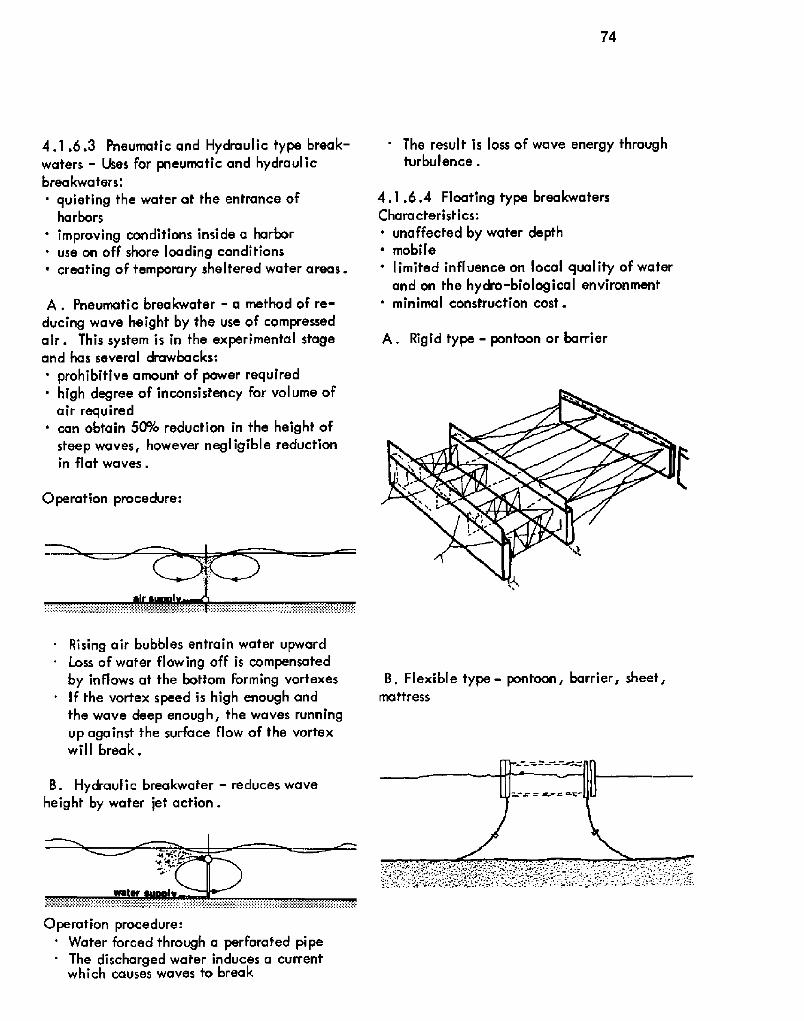
74
Operation procedure:
4.1.6.3 Pneumatic and Hydraulic type break-waters - Uses for pneumatic and hydraulicbreakwaters,'' quieting the water at the entrance of
harborsimproving conditions inside a harboruse on off shore loading conditions
~ creating of temporary sheltered water areas.
A. Pneumatic breakwater - a method of re-ducing wave height by the use of compressedair. This system is in the experimental stageand has several drawbacks:' prohibitive amount of power required
high degree of inconsistency for volume ofair required
' can obtain 5PYo reduction in the height ofsteep waves, however negligible reductionin flat waves.
Rising air bubbles entrain wafer upwardLoss of wafer flowing off is compensatedby inflows af the bottom Forming vortexesIf the vortex speed is high enough andthe wave deep enough, the waves runningup against the surface flow of the vortexwill break.
B. Hydraulic breakwater � reduces waveheight by water jet action.
Operation procedure:Water forced through a perforated pipeThe discharged water induces a currentwhich causes waves to break
The result is loss of wave energy throughturbulence .
4.1.6.4 Floating type breakwatersCharacteristics:
' unaffected by water depth~ mobile
limited influence on local quality of waterand on the hydro-biological environment
' minimal construction cost.
A. Rigid type - pontoon or barrier
B, Flexible type- pontoon, barrier, sheet,mattress

75
4.1.l Terminals
Terminals are the specialized areas of a portwhere points for discharging and receivingcargo are provided for rail, highway, pipe-lines, inland waterway carriers and oceangoing vessels. The controlling factors forterminal layout are:' characteristics of cargo to be handled
handling equipment to be usednumber of outlets For cargo
' vessel types' cargo handling efficiency.
4.1.7.1 General Cargo Terminals' .Forgenerat cargo a facility has to be equippedto handle many different types of cargo. Indesigning a general cargo terminal the fo'I-lowing must be considered:' type oF equipment required
method of cargo handling' fype of transportation vehicles used
open and closed storage space requiredvessel characteristics.
Terminal
ty pes.4.'I .7.1
4.1.7.2
4.1.7.3
4.1.7.4
4.1.7.5
4.1.7.6
4.1.7.7
s are generally classified by cargo
General Cargo TerminalsContainer Terminals
Bulk Cargo TerminalsPassenger Terminal sMilitary TerminalsFree Port Terminals
Fishing Terminals
4.1.7.2 Container Terminals: Containeriza-tion techniques provide the designer the oppor-tunity to design terminal facilities fhat willminimize individual cargo handling therebyspeeding up ship tummround time.
Control I ing design factors:~ need for vast land area
~ circulation and parking area for vehicles' shoreside equipment' vessel characteristics, LASH, Roll-on/Roll-
off, etc.
Source: Jahrbuch der HafenbautechnischenGese I I scha ft
4.1.7.3 Bulk Cargo Terminal: These facilitiesare usually designed for a single Function, thehandling oF loose cargo such as grain, coat,cemenf, sugar, ores, etc.
Basic reqviremenl s:~ storage facilities which may be open or of
etevafor type~ cargo handling equipment for loading and un-
loading which generally includes pressurepipes, conveyors, buckefs, weighing equip-ment, etc,
Bulk cargo terminals vary according to:site less requirement for still water!
' characteristics of material handled dry,liquid, powdered, granulafed, etc.!
' quantity requirements' avaitability and type of transportation mode' type of berthing' proximity to urban areas.

76
An essential part of bulk cargo operations isthe existence of adjacent industrial users suchas flour and lumber mills, refineries, iron andsteel mills. They require water front accessto export their products, therefore the distancefrom the water to their plant location dependsupon the handling techniques involved:
liquid - piped commodities may be locatedseveral miles from water front
~ bulk cargo � handled by conveyors, or similarapparatus may be located several yards fromthe water front.
8ulk terminals generally require deeper chan-nels and larger turning basins than other typesof terminals.
A. Liquid terminals utilize wharf, piers andoffshore mooring depending on water depth,bottom conditions and the rate of unloading .
The only requirement for pier or wharf is alight open structure capable of carrying theweight of the pipes and valves and withstandingthe pressure of the ships. A common policy ista construct ail terminals on the seaward sideaway from commercia'l docking areas.
Offshore mooring generally consists of eithera hose handling platForm or a floating buoy,These facilities do not require heavily pro-tected waters and are constructed in deepwater to facilitate deep draft vessels.
Loading apparatus for offshore terminals:~ submarine hose lying on bottom, used for
hard bottom conditions' Hartley hoister, used where sea bottom is
soft and a high unloading rate is required.
Source: Design and Construction oF Portsand Marine Structures

77
Additional design considerations:~ pipelines and pumping equipment~ tank storage facilities~ fire and explosive hazards.
B. Grain terminals utilize wharf loadingwith direct delivery of grain from storage fothe vessel. Necessary facilities include:. storage bins
pneumatic suet'ion devices' car and frack unloading facilities
weighing facilitieselevators.
Source: Seeverkehrswassebau
C. Ore and Coal terminals
Careful consideration should be given for:' ground. storage and stockpile areas
loading and unloading equipment towerunloaders, grabbing equipment, floatingcranes, efc.!
' vehicle circulation .
4.1.7.4 Passenger Terminals generally separatepassenger fraffic and cargo traffic to eliminafecongestion . The traditional method of accom-plishing this has been to locate passenger facil-ities on a second level over a cargo area . Sincethe passenger levels of ships are generally atupper decks, this separation works very well .
Design considerations:~ peak flow of passengers' baggage requirements' cusfoms requirements~ vehicle access' parking and storage of vehicles' office space for port administrators and
service facilities
waiting and recreation fa cilif ies,
Plan of passenger facility
4.1.7.5 Military Terminals provide militaryvessels with berthing, maintenance, storageand supply facilities. ln developing countries,it is not uncommon to find joint use of a portwith the military.
4.1.7.6 Free Port Terminals represent the de-signation of a port or portion of a port as a "freezone" where goods may be transshipped, manu-factured and packaged, duty free.
4.1.7.7 Fishing Terminals are designed to pro-vide profecfion in time of storms and a place toprocess and market the catch.

78
fixed, tendedfiaed, aeli-conialnedmobile, aubmoraibk
ii ~ i ~ moblk, ekvatlh9
elevatian
Source: Le Tourneau
Offshore, Inc .
plan
and Marine Structures
4.1.B Offshore Structures
Offshore structures may be classified in threegeneral categories:4.'1,8,1 Mobile Wharves4.1.8.2 Radar and Lighthouse Platforms4.1.8.3 Offshore Drilling Structures
4,1.8.'1 Mobile Wharves were developed to beused in areas where construction equipment andmaterials are not readily available and whereon-site construction time is limited. Majorcharacteristics are:
~ prefabricated~ temporary~ portable.
4.8.1.2 Radar and Lighthouse Platforms are usedin navigation and as early warning stations fornational defense . They are permanent structures .
Source. Desi n and Construction of Ports
4.'1.8.3 Offshore Drilling Structures are ofseveral types:
tended, permanent drilling platformsmobile submersibl e drilling structuresdrilling barges or vesselsmobile, elevating drilling platforms.
Types of drilling rigs used in the Gulf ofMexico
Mobile drilling platform in various stagesof erection
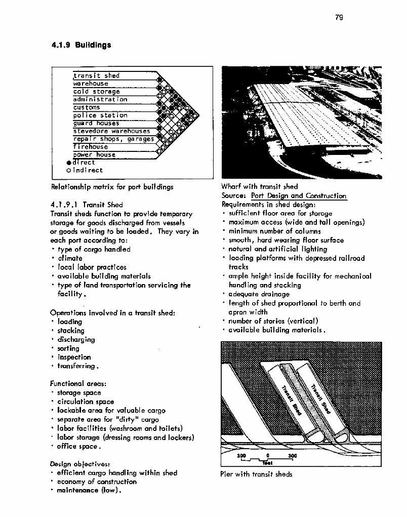
4.1.9 Suildlngs
Pier with transit sheds
Relationship mafrix for port buildings
4.1.9.1 Transit Shed
Transit sheds function to provide temporarystorage for goods discharged from vesselsor goods waiting to be loaded, They vary ineach port according to:
type of cargo handled' climate
local labor practicesavailable building materia Istype of land transportation servicing thefacil if y .
Operations involved in a transit shed:' loading
sfackingdischarging
' sortinginspection
~ tfansferr ing .
Functional areas:' storage space' circulation space' lockable area for valuable cargo
separate area for "dirty" cargo' labor facilities washroom and toilefs!
labor storage dressing rooms and lockers!' office space.
Oesign ob,jecf ives:' efficient cargo handling within shed' economy of construction' maintenance low!.
Wharf with transit shedSource: Port Desi n and ConstrucfionRequirements in shed design:. sufficient floor area for storage
maximum access wide and tall openings!minimum number of columns
' smooth, hard wearing floor surface' nafural and arfificial lighting
loading platforms with depressed railroadtracks
' ample height inside facility for mechanicalhandling and stackingadequate dra inage
' length oF shed proportional fo berth andapron widfh
' number of stories vertical!' available building materials.


83
~ Iaec»aa oosacsese or saacvao saon ocmc vaaeneau
Npnnarac nrnn" mTnnmncm spncn Nrpr pplen aTIIrssn
amissk IL k
eaggrpp.8 ldn lnmnrc k
M IM 3 0 IL irychs m dcyrcoscd wdl mUNRI %8 SMI
Q5Mi
76,2M t h,lt. Ilackl iil dsPiacpdnalt Ndnk515 SNS 25-MptM � Sall% - Soap
ttar!9%
1 5% Spt1 %,5% 2 0 a, Irnht in MDNPml wdl nshedMlt gopw IYNgk 1 Pcw 19gapa 01%5
125 20 5 115 1%1� Ikon!
Pier %1 Mocp Reer!Me 11 � lr Oper0 !Oner
Wan York
25- gert ~2D. SCS% � BwtPtw1%6 M,NN 2 Rh tieCkt i ~ dnicaen «Nl inchad. 'tCmlOmiar liged m snittwnit ai Scop It Utnt hmlr�
M,IMI 2 ~ ~ . Irnht st pmdorrn torsi Nnw d lorpr shel Open hsrtnnil nwtilprcd ih chir Nrripit ~-OllL
Wan imp Twrmad Fod Mnsih! 1%L 2%.lptt 2W 550Ctep Wept I tg sgt2 !,OMMSO Mtt 200% %0
ITS,MM 6% SylCa hr trcckt aa wslmre~ n. !%8% OL g Pmad mel inPM 3 SnklfrrIf WOO TWOICNI! %-Madge. - Slg 2%25 - Wsl1859
lprlek Pmr.pi 1,1% 3% P-UPW 2 !,0% 3% !M,MO 5% M,MM 200 OON«~~l,s!SM 35-immi 2 Ins Niiii iPlnil Prithf25 - face CINNiac ripper p Cr Satori,
Warl !, 5%1%1 12,9% 2 0 S. traps flr platform Instlaencg It rear ol hen thwtsTna Ine-swiss pnlil «ranai in~ harl apn
2 40~ % 152 P5,WM!S2 16 lett shader
Scnmwh Sate Sachs Whwt 2,1OI rid S50 ifi5 22 5 Fl 150 6% td Ic tp 2 a,k Irackt ler ptrdorm torsiIDM 35 1 8% %5 22.5 71.!gt tp 59,UIS lamtmd ~ ! rear M dl sheik TwoMg UU 22 5 %,'Ug fcg.pnat pall! Neon ea alnrl
0 IPDIL
SWa Oede-Slrpa6, 7,6 9 101DDU 2 S.R I scil lor atntwh tmpkrohna ri rtl i Ol it mt
Sergn 6 0 I WMslloperdgp Ypammg- 1917gccdwp, T!,22,28 Ipwt% 6 26 1950la%empt whsnn!
51 1 151 Ipl Usta371 1,162 IMI UohI. Idt W0
I 216tk Soignd1,%5+ 359!,9%+ SM0th - Fem
2% ON MtIM Dlo at 665179,762
ltl tp 7 00, ttachiic hlagarrc laceslard ne sl rssr at sl sd4 S M OIS 2 a.a. Irons tw rnnarm lardhmdnl U Ca st*ca
M 5% metic hainsliost,o co c s-inn argo L pmswpi 1st nsl,M,INI 2flcOrllndmrrr 'Cot n ff hrrtkrm IIOIIU cn tl ilml tcl ~ Irtcrcr'mi loci i'.ll 'teltolccfl circa lc acmeterse ci ta l,pos.aoe. pciIC tc'I 0" I' Itil Item'c D'stra- lc slkn. "C airer at mid
tM 0% !e 7sii lg Onr was' %5
sas Frees!we Mnnp hacL aoshff I,MO tcncn !,1% � fpa opn IcnI ~ rrrisml Pmr 1.109 Dkrl 31 P! Upyer Par 50 !Ã0 5%-Open 31 29 I.axw2 6% 115 I 7SK II92 Ir612 IM 17
ta tp ts 7aa 2l. Il IN' Ops tcrtnr nrn ccnldscdIS UN 1 c S8. I i 'I IN' a i rwsotcrm tt ~ lmrii r91 UW I I I Ico lr 9':do aicrtcrrircisl Micc ol re i'icosor or Mlr hsr cncdpcorUcnwmclift Nl 1 i 551 . I 15 UU st ai CI c 0 inttinre Missal709 0 tt
Ulehp 1,0!8 89S 32 garth 2 901 IICI Ul 10 91U Slc 13 '9N I h 4 Irw i ar pcrnrh lc.ciPin M Smlh 2 PI 110 16 Igt 9%1812 Kt Fax npc U piers n I at rcr r if
rnid92
0 wn
Tonnla Prw 11 Wrtecf MW % IS1%5 I X Ul !CO tdg MO iU WO I x« ir rrl c' ll c catTi'i rcl hc I ri 'crim nrr ri .". swam tnc corm Om,I p I rrri
Sr5
Ulcc .CN32 S Oarln I32 5-Soslh IhpnNNM Ptw IUI, 2 PmrIMsnnpal 5MS'I 1%1 1.0!f-gorS10!T.Sang 5% 50l IM 10 tl 71 xo ti Mo tl .IUD I vii d rat nprcemc ca oc50l 150 tky 7I,UU alai Pc tel c dsdr I'c liat:I, Wl ides lr rs i srsrdlrw c.OW
IM!ISS: Dg Icmmd dmds opcam7 ncayl nlNNDONnrma wont osdp Mrnenh"Ssgngpgatk Nnc snkalalaidn wc! lpw mmalacap DIML
%1 - Spp%8 � 0lrp
5!S Wnt5% - Teat
Wharf 1 Ogt !I I %! %9 tt 312 MO lt 515IPM C% 31 la 0%
l«daSetca IMNIN 195, Bh, I ~ I whorl 92,2M I pe6 1% 1%1I W corp<I Wlnmrot
Reproduced by permission of the AmericanAssociation of Port Authorities
01,5gl TcmcUM trannt atoll � growSia ~ Coirillnalcm ncrgl Wid Onc-rcrgar lrrmmg rlh pwaniigp~or in heargnn.

82
Recenf trends in shed construction are
toward multisfory transit sheds up to 6stories! .
Advanfages:' provide long time storage space' minimize land requirements' segregate import-export operations' reduce roof area
' distribute work area over several floors
' facilitate customs clearance.
Disa dvanfages.~ require vertical delivery facilities' require stronger, heavier foundations
increase construction costs
. require more columns' require more circulation space.
Section and detail of multistory warehouseSource: Port of Stockholm, Sweden
Cargo flow in a fwo story transit shed

83
Mul ti story Warehouses
4.1.9.2 WarehouseThe primary Function of a warehouse islang time storage.
Factors to be considered in designing awarehouse:
~ temperature
~ humidity~ air movement
~ equipment dimensions and clearances- distance from berth ar transit shed
~ optimal column spacing For longer spans~ loading platforms~ ra ilroa d ca pabil ities~ covered loading areas' wall cranes or travelling cranes.
Dimensional criteria:
' availability of space~ use of warehouse
' for fire protection structure should becorn par tmenta I ized
' provide minimum of 2 feet clearancebetween top of cargo and ceiling.
Advantages of constructing warehouse abovetransit sheds:
cargo can be transferred from transit shedto warehouse regardless of weather conditions
' provides minimum distance for cargo move-ment
' reduces external traffic congestion.
Typical Warehouse LayoutSource: Jahrbuch der HafenbautechnischenGesel lschaft
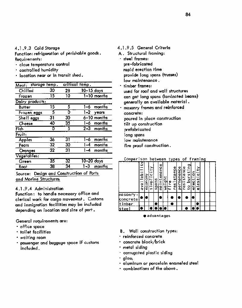
84
Dair roducts;1-6 months
1-2 ears
6-10 months1-6 mon ths
2-3 months0 5Fis
Fruit:36 31
32 3032 3'I
1-6 mont s1-4 months
1% months
A les
1-3 mont sRoot
~ adva nta ges
4.1 .9.3 Cold StorageFunction: refrigeration of perishable goods,Requirements:~ close temperature control
control I ed humi dity' location near or in transit shed.
Meat; storage tern . critica tern
Chilled 30 28 10-'l5 da sFrozen 15 10 1-10 months
Butter 15 5Frozen e s 5 0
She I I e s 31 30Cheese 40 35
Ve eta es:Green 5 32 10-20 days
Source: Design and Construction of Portsand Marine Structures
4.1 .9.4 AdministrationFunction: to handle necessary office andclerical work For cargo movement. Customsand immigration Iacilities may be inc'ludeddepending on location and size of port.
General requirements are:' office space
toilet facilities
' waiting room' passenger and baggage space if customs
included.
4.1.9.5 General CriteriaA . Structural Framing:
steel frames:
pre-fabricatedrapid erection timeprovide Iong spans trusses!low maintenance ~
' timber frames:used for roof and wall structurescan get long spans laminated beams!generally an available material .
' masonry frames and reinforcedconcrete:
poured in place constructiontilt up constructionprefabricatedlong spanslow maintenance
fire proof construction.
B Wall construction types.' reinforced concrete
' concrete block/brickmetal sidingcorrugated plastic sidingglass
~ aluminum or porcelain enameled steel' combinations of the above.
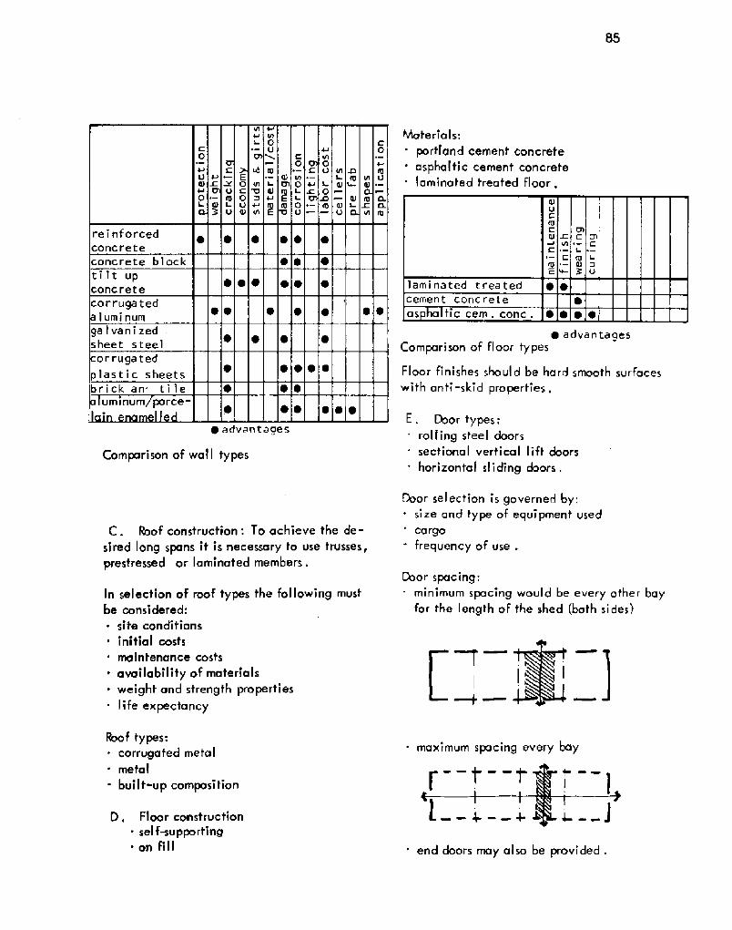
85
~ advantages
Comparison of wall types
C. Roof construction: To achieve the de-
sired long spans it is necessary to use trusses,prestressed or laminated members.
In selection of roof types the following mustbe considered:
~ site condition s
initial costs
maintenance costs
~ availability of materials. weight and strength properties
life expectancy
Roof types.. corrugated metal
metal
buil t-up composi tion
D . Floor constructionsel fwupporting
~ on fill
hAate ria I s:
' portland cement concreteasphaltic cement concretel a mina te d treated floor .
~ advantagesComparison of floor types
Ftoor finishes should be hard smooth surfaceswith anti -skid properties .
E. Door types:rolling steel doorssectional vertical lift doors
horizontal sliding doors .
Door sel ection is governed by;size and type of equipment used
cargofrequency of use .
Cbor spacing:minimum spacing would be every other bayfor the length of the shed both sides!
maximum spacing every bay
end doors may also be provided
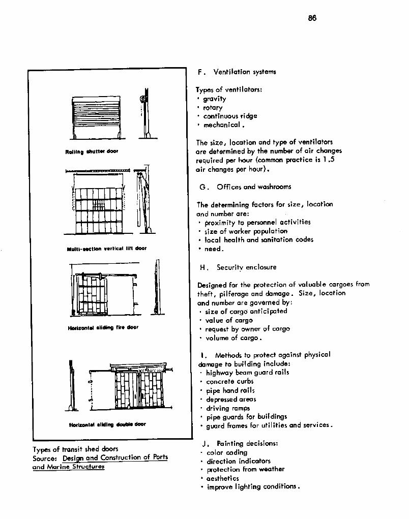
F . Ventilation systems
H, Securitv enclosure
Types of transit shed doorsSource: Desi n and Construction of Portsand hharine Structures
Types of ventilators:' gravity' rotary
continuous ridgemechanica I .
The size, location and type of ventilatarsare determined by the number of air changesrequired per hour common practice is 1.5air changes per hour!.
G. Offices and washrooms
The determining factors for size, locationand number are:' proximity to personnel activities
size of worker population~ local health and sanitation codes
' need.
Designed for the protection of valuable cargoes framtheft, pilferage and damage. Size, locationand number are governed by:
size of cargo anticipated' value of cargo~ request by owner of cargo' volume of cargo.
I, hhethods to protect against physicaldamage to building include:
highway beam guard rails~ concrete curbs
' pipe hand rails' depressed areas
driving ramps' pipe guards for buildings' guard frames for utilities and services.
J. Painting decisions.. color coding. direcfian indicators
protection from weather' aesthetics
improve lighting conditions .

87
M, Electr i ca I suppl ystandard 110/220 volt 3 way system208/120 volt 3 phase system480/277 4 wire system .
4 4 4
mercury vapor
35 feet!,
~ advantages
Chart to determine length or width of shedor warehouse based on desired square footage
lc,, Fire protection systems~ automatic sprinklers~ supervisory fire alarms~ fire walls
. auxiliary fire fighting equipment hoseracks, chemical fire extinguishers, etc.!.
L. Lighting' .general requirements for alighting system are for it to produce diffusedlight without harsh shadows or glare.
available light natural! provided by:roof lighting skylights, cleorstory, etc.!side wall lighting glazing, translucentpanels, etc,!artificial light for night operations or fosupplement natural light ..
Types of artificial light:~ incandescent
fluorescent
minimum vertical distance
The general practice has been to provide 10foot candle illumination indoors and 1 footcandle iflumination outdoors for transit sheds
and warehouses,
Comparison of type of f ixtures
4- 4- 4-
g o o
OO QOOOOOO
Lengthft.
8 F8osoOOOO lO 0O R EC!

88
4.1.10 Dock Types
Marginal wharf
Pier 90o to channelPier at angle tochannel
T-head pierOpier~ wharfL-shaped pier
The most' basic part of port facilities are thedocking facilities for the vessels.
Types of berthing facilities:4,1.10,1 Pier4.1.10.2 Marginal Wharf4.'l .10.3 Specialized Berthing
Controlling factors for dock selection are:. type of cargo' vessel types and sizes
life expectancy of facility' direction of wind and waves
bottom conditions
construction costs
' ownership.
4.'l. l0.1 Pier: a structure extending outwardat an angle from the shore into the navigablewaters of the harbor, permitting vessel berth-ing on both sides.
Piers are constructed because they provide moreberths per linear length of channel than wharvesdo ~
T-head and L-shaped piers are economical waysto provide docking facilities in deep water whicheliminate dredging .
4.1.10.2 Marginal Wharf: wharves extendingparallel with the shore line and connected to theshore at more than one point which allow berth-ing to take place on only one side.
Wharves generally permit:construction of terminal facilities on the landside of the bulkhead line
' high degree of design flexibilityprovision of loop rail and highway connectionsreduced distance for land carriers to transit
shedseasier in docking vessels
' less maintenancemore adaptability to changing requirementsbrought about by new developments in vesseltechnology, cargo handling systems, trans-portation techniques, etc .
Site conditions determine pier or wharfse'lection .
Factors governing the size and shape of pieror wharf layout:~ age and development of the port~ size, shape and dollar value of available land~ vessel characteristics~ trade requirements

89
Evolution of an apronSource: Jahrbuch de Hafenbautechnischen Gesellschaft
amount of dredging necessary for maintenancedepth of wafer
' type of cargo~ cargo handling methods
codes and regulations' types of equipment used for cargo,
Water depth required:open docks one foot more than maximumvessel draft!enclosed docks not less than entrance sill!.
Vehicle use on dock facilities depends on:strength of structure
~ equipment used' cargo handling method
available space~ volume of shipping' number of berths.
General requirements for land vehicles:road and rail should serve parallel to berth
- minimum tracks 2 but not more than 5maximum
berth railroad tracks should be shuntedindependently fram neighboring sheds
' one rail track should be located near theedge of the apron .
General requirements for piers and wharves:elevation of surface should be a minimumof 5 feet above the high water level markat maximum tide
' should have slips wide enough to aIIow shipsto be safely navigated to permit dockingshould be broadside to the prevailing wavefront. It is desirable to have the vesselanchored parallel to the direction of theprevailing winds. If this cannot be achievedthen the berth should be oriented in sucho manner that the wind holds the ship awayfrom the dock.

c f c
Recommended clearance dimensions for wharves,piers and slips
A . Wharf
1 I e 1 e I
B. Two-berth pier and slip
C. Four - berth pier and slip
a � area of transit shedb "minimum of 75 feetc � beam of vesseld - minimum of 100 feete - minimum of 50 feetf � minimum of vessel beam plus 150 feetI - length of vesselFactors affecting pier slip width are:
length of pier' beam of ship using pier
requirements for tugs or lighters which includevessel handling, docking and maneuveringspace}.
Type of construction utilized for piers or wharvesare determined by:' specific operational requirements of the pro-
posed terminal' availability, cost and anticipated life of con-
struction material
structural requirements' local foundation conditions.
Construction Types:A . Open type
~ receiving platform in which the main struc-turol slab is below the finished deck or sur-
face and the space between is filled to pro-vide additional weight for stability

~ high level decks in which the deck super-structure system is supported directly onpiles. The piles are arranged in trans-verse rows. The deck is generally con-crete, precast and prestressed.
8, Solid fill type .'~ steel sheet-pile cells: used where water
depth does not exceed 50 feet and bottomconditions are suitable to support a gravitystructure
~ sheet-pile bulkhead: constructed oF wood,steel or concrete sheet piling and support-ed by tie rods attached to an anchor or bya pile located a safe distance in the backof the face of the bulkhead or by batterpiles along the rear of the piles
Source: Port Design and Construction
rock-fil led timber crib: used for earlyconstruction of piers and wharves. Thetop of the timber crib is usually terminated.at a low water level and the retaining wallabove is constructed of concrete or masonryon which the dock paving is placed
- concrete caissons used extensivety inEurope I. Usua I I y o f two ty pcs:~ open well type sunk in the dredged
bottom for increased stabilityclose bottom type which is set on
a gravel or crushed stone bed
- gravity quay wal I usually construc-ted of 20 � 200 ton precast concreteblocks !.

92
4.'I .10.3 Specialized BerthingA . Lighterage berthsB. Ihmped cargo berths
A . Lighterage berths - for intermediatetransfer of cargo between land and waterconveyance when insufficient water depthexists for large vessels and deep water berthsare not economically feasible to construct.
8. Ihmped cargo berths - gently slopingwharves with adjustable ramps. They areused extensively for Roll-on/Jbll-off cargo.
Ihmped Cargo Herth, Kiddapore Docks-CakuttaSource: Mission Port Develo ment

93
4.1.11 Orydocks
The function of dry docks is to providemaintenance and repair on the underwaterportion of a vessel.
Types oF dry docks:A. Graving DocksB. Floating Dry Docks
Sl i pways Large tanker in drydockSource. Lisnave - Estaieiros Navais de Lisboa
~ advantages
Comparison between graving and Floatingdrydocks
Slipways provide a recessed bed plus mechani-cal hauling facilities to haul vessels out ofthe water,
Source: Seeverkehrswasserbau
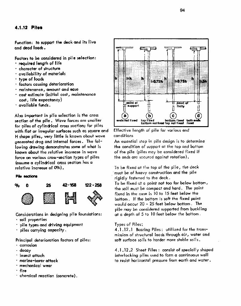
94
4.1.12 Pilee
Function: to support the deck and its liveand dead loads.
Factors to be considered in pile selection:' required length of life. character of structure
' availability of materials' type of loads. factors causing deterioration
maintenance, amount and easecost estimate initial cost, maintenancecost, life expectancy!
' available funds.
Also important in pile selection is the crosssection of the pile. Wave forces are smallerfor piles of cylindrical cross section; for pileswith flat or irregular surfaces such as square andH shape piles, very little is known about wavegenerated drag and internal forces. The fol-lowing drawing demonstrates some of what isknown about the relative increase in wave
force on various cross-section types of piles assume a cylindrical cross section has arelative increase of 0%!.
8m'+Considerations in designing pile foundations:
soil propertiespile types and driving equipment
' piles carrying capacity.
Principal deterioration factors of piles:corrosion
~ decay. insect attach
marine-borer attack. mechanical wear. fire
. chemical reaction concrete! .
Effective length of pile for various endconditions
An essential step in pile design is to determinethe condition of support at the top and bottomof the pile piles may be considered fixed ifthe ends are secured against rotation!.
To be fixed at the top of the pile, the deckmust be of heavy construction and the pilerigidly fastened to the deck.To be fixed at a point not too far below bottom,the soil must be compact and hard. The pointfixed in the case is IO to 15 feet below thebottom. If the bottom is soft the fixed pointwould occur 20 - 25 feet below bottom, Thepile may be considered supported from bucklingat a depth of 5 to 10 feet below the bottom.
Types of Pifes',4.1.12.1 Hearing Piles: utilized for the trans-mission of structural loads through air, water andsoft surface soils to harder more stable soiIs.
4.1.12.2 Sheet Piles: consist of specially shapedinterlocking piles used to form a continuous wa'llto resist horizontal pressure from earth and water.
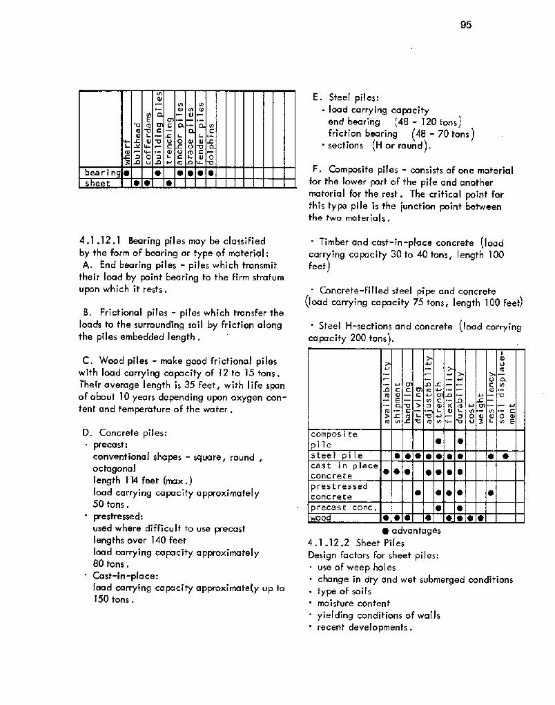
95
4.1.12,1 Bearing piles may be classifiedby the form of bearing or type of material:A. End bearing piles � piles which transmit
their load by point bearing lo the firm stratumu pon which it resf s,
8. Frictional piles � piles which transfer theloads to the surrounding soil by frictian alongthe piles embedded length .
C, Wood piles � make good fricfional pileswith load carrying capacify of 12 to 15 tons.Their average length is 35 feet, with life spanof about 10 years depending upon oxygen con-tent and temperafure of the water.
D. Concrefe piles:~ precasf:
conventional shapes - square, round,octagonallength 114 feet max.!load carrying ca pacify approximately50 tons.
. prestressed:used where d'rfficult to use precastlengths over 140 feetload carrying capacity approximately80 tons.
' Cast-in-place:load carrying capacity approximate y up to150 tons.
E. Steel piles:~ l oad ca rry ing ca pa cityend bearing �8 � 120 tons!friction bearing �8 � 70 tons }sections M or round!.
F. Composite piles - consists of one materialfor fhe lower part of the pile and anothermaterial for the rest. The crifical point forthis type pile is the junction poinf betweenthe two mater i a I s .
' Timber and cost-in-place concrete loadcarrying capacity 30 to 40 tons, length 100feet!
Concrete-filled steel pipe and concrete load carrying capacity 75 tons, length 100 feet!
' Steel H-sections and concrete load carryingca pacify 200 tons!.
~ advantages4.1.12,2 Sheet Piles
Oesign factors for sheet piles:~ use of weep holes~ change in dry and wet submerged conditions~ type af soils' moisture content
yielding conditions of wallsrecent developments .

Major types of sheef piles:A, Steel sheet piles. variety of shapes- adaptable for cellular retaining walls and
cofferdam construction' advantages over other typesin areas of
strength, salvage value, simplicity, hand-ling and heavy construction.
8. Concrete sheet piles � reinforced or pre-stressed, precast piles of rectangular crosssection,
C. Wood Sheef Piles � used to resist lightlateral 'loads.
Section thrM preceet concrete cheat plica
The primary use for sheet piles is in retainingwall constrvction.
Piles are driven into the earth by pile drivinghammers:' drop hammer
sing lemcting steam hammerdovble-acting steam hammer
4.4.13 Fender Systems
The function of a dock fender system is foprevent ships or docks from being damagedduring mooring, by control ling ship motionand reducing or eliminating the impact ofship-dock contact, The fender also pre-vents damage due to rubbing.
Design Factors for a fender sysfem:' vessel characteristics
vessel speed~ approach direction~ wind
expected tidal current conditionsrigidity and energy-absorbing characteristicsof the dockinitial cost and mainfenance costs vs, shipand dock repair costs with a fender system.
Materials to be used for fenders must possess theFol lowing requirements:~ high compressive strength
high fiber hardnesshigh ben ding stressdurability.
Classification oF fender systems is by materialused or the principles of operation:A . Wood Fender systemsB . Rubber fender systemsC. Flexible spring! fender systems0. Gravify fender systemsE . Floating fender systems
A, Wood fender systemsSingle timber "rubbing strip" Fender � Usedwhen the approach to the berth is sheltered, thewater calm and when tug assistance is available .The wood is the element absorbing the impact energy

Timber fender with two or three horizon-tal walls together with vertical timbers. Usedwhere tidal range is relatively small . Theyhave a low initial cost and have proven to beeconomical in replacement.
~ Timber fender plus fender piles. Usedwhen addltionaI energy absorptions are desiredand tidal ranges are greater than six feet
Timber fendering with cylindrical rubberunits. Used where greater deflection andenergy absorption is required.
When using wood fenders, it is necessary to:use only sfress graded timberdrill bolt holes to the same diameter as thebolfs
~ protect all cuts with creosofe' use only galvanized bolts.
Timber fenders on sheet pile bulkheads
B. Rubber fender systems - have generallyreplaced the use of flexible - spring type offenders because they have:~ longer life' less maintenance
better absorption of longitudinal forcesparallel to the dock.
Source: Desi n and Construction oF Ports
and Marine Sfructures, A.D. Quinn, 1961,McGraw Hill . Used with permission of Mc-Graw Hill Hook Company
Types of rubber fenders:Rubber-tire truck-wheel fender Utilizes
truck tires on wheels, placed in a horizontalposition along the face of the dock. Suitablefor calm waters and a small tidal range!
' Hollow-rubber cylinder fype Requires asolid fascia wall to a depth of at least sixfeet because of the curvature of the fender.
This type is adaptable to solid type dockconstruction j

Raykin fender buffers
' Combination steel beam and rubber fendersystem with steel fender piles Utilizedwhere it is not practical to use deep dockfascia beam ol wal I !
Raykin fender buffer Consists of a seriesof connected sandwiches made of steel plates,cemented to layers of rubber!.
C. Flexible fender systems � utilize steelspring fenders for additional energy absorptionor spring type wood fenders which are placedaway from the dock at a slight angle <:24!to absorb energy by deflection.
Typical springing-type wood fender
Source: Design and Construction of Portsand Marine Structures
D. Gravity fender systems � based on theprinciple of transformation of kinetic energyinto potential energy by means of raisingweights massive blocks of concrete! utilizing:~ system of cables and sheaves~ pendulum
trunno ins .
Suspended gravity fenders
E. Floating fender systems � used generallyto keep ships away from a dock or to separatevessels which are tied up adjacent to oneanother .
Types:~ rol ling type~ heavy timber box section type' floating fender log type.
Rubber tired fender and a timber pole fenderSource: Port Desi n and Construction

99
4.1.14 Mooring
Iriser clNin
QrOUIld ChSi4lsinker
Function: to anchor or tie up vessels for thefol low ing reasons:
waiting For a vacant berth' working cargo overside only
waiting in calm waterwaiting for dry dock or repairs
' to take on cargo for super-sized tankers.
Types of mooring:~ vessels own anchor
~ i.ie up to buoys' combination of buoys and anchors
tying up at a berth.
Components of a mooring buoy
Multiple mooring buoy arrangements
Source: Design and Construction of Portsand Marine Structures
A vessel should be moored as close to shoreas possible with its approach to the buoybeing into the wind and parallel to anycurrents .
Number of buoys utilized for mooring de-pends upon:
vessel size and characteristicswinds, currents and waves
' bottom conditions
economic factors.
Typical mooring accessories
Spacing of the mooring devices is based on:~ vessel characteristics
' convenience of cargo handling' wind and tidal conditions.
All mooring devices with anchorage are de-signed for worst conditions with a 50% safetyfactor added.
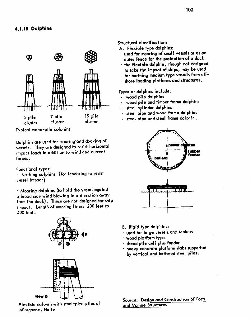
300
4.1.15 Dolphins
19 pilecluster
a
3 pile 7 pilecluster cluster
Typical wood-pile dol phins
Dolphins are used for mooring'and docking ofvessels. They are designed to resist horizontalimpact loads in addition to wind and currentforces.
Functional types:~ Berthing dolphins for fendering to resistvessel impact!
' Mooring dolphins to hold the vessel againsta broad side wind blowing in a direction awayfrom the dock!. These are not designed for shipimpact, Length af mooring lines: 200 feet to400 feet.
Flexible dolphin with steel-pipe piles ofMiragoane, Haite
Structural classification:A. Flexible type dolphins:
used for mooring of small vessels or as anouter fence for the protection of a dock
' the flexible dolphin, though not designedto take the impact of ships, may be usedfar berthing medium type vessels from off-shore loading platforms and structures.
Types of dol phins include:~ wood pile dolphins~ wood pile and timber frame dol phins
steel cylinder dol phins~ steel pipe and wood frame dolphins~ steel pipe and steel frame dolphin.
B. Rigid type dolphins:' used for large vessels and tankers
wood platform typesheed pile cell plus fender
. heavy concrete platform slabs supportedby vertical and battered steel piles ~
Source: Design and Construction of Portsand Marine tructures

101
4.1.16 Nloles, Trestles and Catwalks
Moles, trestles and catwalks are designedfor access from the shore to pier or terminal .
A. Moles - constructed of rock Fill withsloped sides for protection from erosion,similar to breakwater construction . Thefunction of the moles is to support roads,sidewalks, railroad tracks, utilities, pipe-line, conveyors, etc.
Cross section of a typical rock mole
8, Trestle - lighter construction than piers.They are designed primarily for verticalloads. The majority of trestles use precastand prestressed concrete decks because ofdura b i I i ty and economy .
Cross section of timber trustle on wood piles
Source: Design and Construction of Portsand Marine Structures
C. Catwalks - used to provide access fromone dolphin to another. They are generallylight weight construction, wood or steel . Cat-walks are located af a distance from the faceof the structure to prevent damage by vehiclesor vessels.

5 Trends
eo ';

103
This publicafion demonstrates an insightinto the complex problems involved in portand harbor design and construcfion. It isintended to serve as a starting guide to thevarious planning procedures necessary todesign a port or harbor.
The following lisf presents selected trendswhich it is believed will have the greatestimpact on ports of the future:
Functional obsolescence of port Facilities isbecoming increasingly apparent as ship con-struction technology advances. New innova-fions include:
deep draft vessels 80 feet! that exceed allchannel and harbor depthsLASH and SEABEE concepts that requireentirely different facilities
' standardization of ship componentstransocean barge concepts
' automatecl vessels confrolled by ship boardcomputers .
Movements to off-shore loading systems in orderto efficiently use deep draFt vessels. The onlycargoes loaded off-shore presently are liquid,such as oil and slurried ores.
New Facilities for oFF-shore loading vary fromsubmerged pipel ines to artificial island installa-tions .
Containerization is revamping cargo handlingtechniques .
Harbor obstacles are influencing new porfthinking:~ expensive dredging costs. expensive relocation costs of tunnels,
pipelines, etc.~ environmental and ecological factors.
Development of coastal barge terminals fo pro-vide secondary distribvfion centers.
Specialized ports; a limifed number of larger,regional type ports wifh sophisticated equip-ment designed to handle a specific type ofcargo. An example would be a regional con-tainer porf.
lnfermodal transportofion; a highly organizedand scheduled, Factory-fo-user chain under asingle bill oF lading . This system requires agreat deaf of sfandardization of components toenable all transport modes to equally participate.
Improved conditions for porf labor:~ provide and mainfain hygiene locker, dining
and toilet Facilities
- improve recruiting programs' improve and implement training programs to
facilitate highly skilled dock workers.
Improve and enforce safety standards and pro-cedures for personnel, facilities and harborsto reduce accidenf frequency .

6 Corcepts 104
6.1 Existing Port105
6.1.1 introdLtction
In the pasf few decades, while trucking,rail and air operafions have sharply risen,the shipping industry has declined. Tobetter compete, the shipping industry hasintroduced technological advances includingincreased ship size ond containerization ofgeneral bulk cargo. Rut white fhe shippingindusfry has made great sfrides in shipbuild-ing and containerization, mosf of fhe portshave not kept pace.
A major problem facing ports today is thetask of modernizing obsolete facilities, equip-ment and methods. The large marshallingyards required for containerization have nofbeen constructed in many instances, usuallybecavse of lack of available land. Manyports have been unable to cope with the in-creased truck traffic due fo limited accessroads, and shipping lanes are often toonarrow and too shallow to handle the new
superships. Such obsolete facilities oftenforce shippers to ship from ports with newfacilifies, thereby diminishing the older ports'cash inflow at a time when they can leastafford if .
In these older ports, the lack of space is amajor problem. They are typically located inthe oldesf part oF the city where narrow, con-gested sfreets do nof permit adequafe trucktraffic For transfer and delivery of cargo. Thewaferfronfs are characteristically packed withobsolete, decaying piers and wharves whichinhibit port efficiency.
The lack of appropriate planning far advancedmarine technology has created expensive de-lays in fhe loading and unloading of ships.Valuable land is often occupied by piers andwharves with aprons too narrow for eFficientcargo handling, and ship turn around time isoften needlessly lengthened by narrow channelsand congestion caused by improperly locatedindustrial sifes.
The older port could greatly increase ifsefficiency by gradual fy eliminating facilitieswhich are inefficienf, unprofitable or unfitfor modern operations because of size or loca-tion. The remaining terminals and facilitiescould be upgraded and a logical expansion plandeveloped to forestall premature functionalobsolescence .
A port can be of great economic benefit to acommunity by attracting frucking, sforage anddistribution concerns; providing jobs within theportand stimulating secondary work opportuni-ties outside; attracting port associated indvsfries;and bringing an increased flow of goods throughthe entire area. However, without proper plan-ning for transportation, Facilities and increasedtraffic flow, fhe port can become a hindranceto community progress, especially in the faceof today's rapid change.
The objective of this part of the report is fo citeimprovements which could be implemented inexisting ports. This includes aspects of portplanning, facility design and handling methodswhich would allow better land usage in theport and its surrounding area; more r'egard forthe physical and social environment oF fhe portareas; and techniques for effecting more rapidturn around of ships. The aim is not to advanceport technology so that it is more competitivewifh trucking, rail and air transport systems,but to promote better coordination of thesetransportation modes.
To il lustrate how modern facilities and betterplanning can reduce congestion within a portand increase the efficiency of its operations,the Port of Galveston has been chosen as a casestudy. The case sfvdy wilt concenfrate on newconcepfs of cargo handling which include multi-purpose warehouse - transit shed buildings anda system of vertical container storage and re-trieval . The possible svbsequent need for re-moval and relocation of exisfing Facilities wil Ialso be considered.

106
6.1.2 Port of Galveston-Case Study
History:Galveston Bay, probably the finest naturalharbor on the Gulf, is protected against theopen sea by Galveston Island. The harboropening is the pass between the island andBolivar Point. Galveston Island has such asuperior position on the coast fhat if becamethe first port in Texas and, since the middleof the nineteenth century, has served as thelargest cotton exporter in the nation. Thefirst railroads crossed the causeway toGalveston in I860 and goods exported fromTexas began to funnel through Galveston.Except for the rapid growth of the Port ofHouston and Galveston Island's susceptibilityto storms, the Port of Galveston could possiblyhave been the major seaport in the Gulf ofMexico .
Bui I ding s:Many of the present port buildings in Galvestonwere built in the 1920's or before and are inextremely bad repair . Since 1956 the Port ofGalveston has spent approximately $25 millionon repairs and renovations of these buildings,The transit sheds are of concrete, tin and wood
construction with foundations of concrete pilingsand beams. Some aprons are still extremelynarrow, however, several of them have been
widened and have had rail lines added to them.These wider aprons can be servicedby rail typeor shoreside cranes.

107
The warehouse district is intermingled withresidential areas of extremely poor quality .Very little delineation is made between com-mercial and residential areas with houses and
apartment complexes being simply insertedbetween warehouses and compresses. If thestorage facilities were relocated, warehousesand land could be converted to housing and re-creational areas. Several warehouses have al-
ready been sold and replaced with apartments
and shopping centers . Cotton is transferred by tractor trains consistingof strings of eight or ten cars pulled by smalltractors. This has proven to be the most efficientmethod of cotton transfer so the port is planningto ex pan d i ts program .
Circulation:
Warehouses and transit sheds are serviced bynarrow congested streets, and heavy trucktraffic is impeded by the maze of railways inthe area. Railroad spurs to several of the ware-houses have long been clogged by rubbish andovergrown by weeds. Tracks in the area of thecotton compresses and warehouses are often un-used due to lack of repair.

108
syaltlstoryWarehouse /Transn Shed
Expansion:Due to the age of Galveston, the port iscrowded with old buildings, streets and rail-ways. This limits space for expansion of theport �6 acres within the port and several in-dustria I areas are available! .
Expansion on Pelican Island is limited due topresent tenants, and plans for the future arealready in progress. Presently on PelicanIsland are Todd shipyards, the site for TexasMaritime Academy, the site for the Seabeebarge terminal, several marine oriented in-dustries and chemica'I and petroleum termi-nals. Future plans for the island are to zoneit for residential, recreational and commer-cial areas. Galveston Wharves the Port ofGalveston! presently owns only 48 acres onwhich the Seabee barge terminal will be built
Multistory Warehouse jl ransit Shed:One of Galveston's mator problems is presentlythe lack of available land for new facilities.
To reduce the space now occupied by outdated,single-purpose warehouses there is a possibilityof combining transit sheds and warehouses intosingle buildings, with the lower floors fortransit cargo and the upper floors for long term
storage. The combination of these two Faci-lities could reduce the time required to movecargo from the docks, through the transit shedsand to the warehouses. The cargo For storagecould be unloaded directly into the ware-house from the ship. Within this multipurpose

109
CWt IIVVVIVVVull
Laneitudinai Section
ranaveraa Section
building could exist transit storage areas,rail and truck circulation, refrigerafed stor-age, general storage, privafe renfal spacesand office spaces For port officials or ship-ping related industries.
To further implement the efficiency of thesemulfipurpose strucfures, covered facilitiescould be used for loading and unloading, en-abling cargo to be stored and handled in alltypes of weather. Wii'h no losses of man hoursbecause of rain or ice, the efficiency of theFaciHty would be increased and ship turnaround time improved.
Where multistory sheds are used in conjunc-tion with slips or finger piers, if would be asimple mafter fo cover the span with a spaceframe, a vault, a cable-supporfed strucfureor a cantilevered roof. 'ln the case of a shed
alongside a marginal wharf, a cantileveredor cable-supported roof system could cover theapron and the ship. With the facilitiescovered, the upper floors of the buildingcould then open onto the apron withoui fearoF weather damage, except in extremely harshclimates, This would allow cargo intended forrefrigerated sforage or long term storage to beunloaded directly onto the level desired.
Cargo could be loaded from the upper floors bya gantry type crane, moving on tracks along theapron. Cargo could be brought fo fhe edge affhe warehouse where it would be picked up bythe crane . A system of small ramps or balconiescould be used to pick up cargo from fork trucks.These balconies could be lowered for the forktrucks to drive onto them and raised when theywere driven off. This would allow cranes to
pick up and drop cargo without any overheadobstructions .

110
Rail and truck circulation within the buildingwould be carried out on different levels,Railcars would enter the warehouse on a levelslightly below the apron level to allow easierloading and unloading . Lanes would be pro-vided on the first level for trucks to enter be-tween the railroad tracks but the maIor trucktraffic would enter the warehouse on thesecond level .
Vertical circulation within the warehouse woul d
be accomplished by lifts or elevators, overheadcranes and conveyors and ramps. Verticaldistribution of goods for storage from ships wouldbe accomplished by the dock cranes or overheadconveyors .
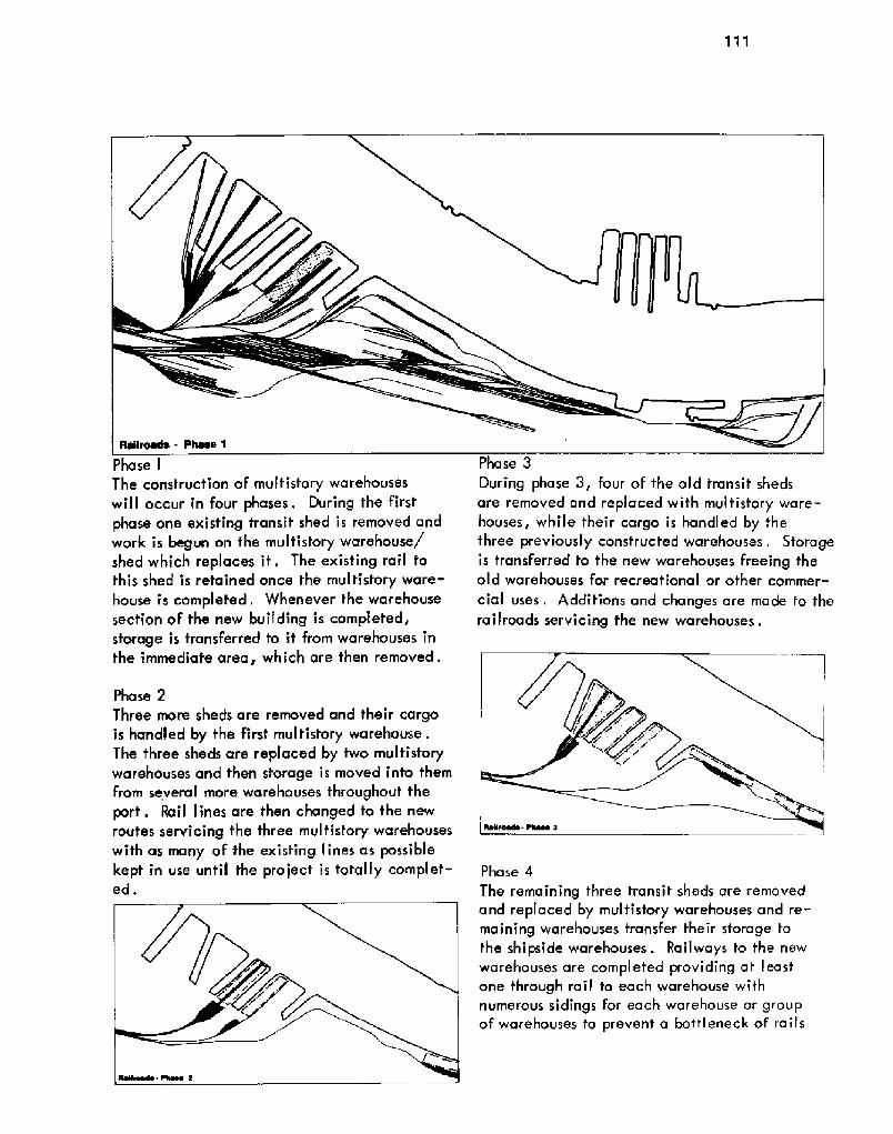
111
Phase IThe construction of multistory warehouseswill occur in four phases. During the firstphase one existing transit shed is removed andwork is begun on the multistory warehouse/shed which replaces it. The existing rail tothis shed is retained once the mul tistory ware-house is completed. Whenever the warehousesection oF the new building is completed,storage is transferred to if from warehouses inthe immediafe area, which are then removed.
Phase 2
Three more sheds are removed and their cargois handled by the First multistory warehouse.The three sheds are replaced by two multisforywarehouses and then storage is moved info themFrom several more warehouses throughout fheport. Rail lines are then changed to the newroutes servicing fhe three multistory warehouseswith as many of the existing lines as possiblekept in use until the project is totally complet-ed.
Phase 3
During phase 3, four of the old transit shedsare removed and replaced with mul tistory ware-houses, while their cargo is handled by thethree previously consfructed warehouses, Storageis transferred to the new warehouses freeing theold warehouses for recreational or other commer-
cial uses. 4dd'rtions and changes are made to therailroads servicing fhe new warehouses.
Phase 4
The remaining three transit sheds are removedand replaced by multistory warehouses and re-maining warehouses transfer their storage tothe shipside warehouses. Railways to the newwarehouses are completed providing at least'one through rail fo each warehouse withnumerous sidings For each warehouse or groupof warehouses to prevent a bottleneck of rails

112
in the waterfront area. Various switchespreceding the entrance to the waterfront areaand around the warehouses allow railcars to
be rerouted . Container FacilitiesWork is already underway on Galveston's firstcontainer facility. Two existing slips are beingfilled to gain 66 acres for a container marshall-ing yard. Storage will be available For approx-imately I800 containers stacked two high. Con-tainers will be moved by trans-tainers fromtrucks to the stacks and from the stacksto the container crane.
Approximately l700 feet of berthing space wil Ibe obtained by the filling in of the slips, allow-ing berthage for two container ships. At present,one of the slips has been filled and the facilitywill be open early in 3972, The remaining slipis to be filled later.
Vertical Container StorageInstead of filling in the remaining slip and con-verting the entire 66 acres into a marshallingyard, fhe slips could be widened and a systemof vertical container storage could be utilized.By not filling in the slip, berthing for four shipscould be provided.

113
With a vertical storage system, room could beprovided for up to 2500 containers IO high!,plus a considerable savings in land. Fewerpeople would be required to operate such afacility, therefore, part of the labor forcecould be channelled into other port operations.By creating certain zones for rail and truckunloading, congestion will be kept to a mini-mum .
Future expansion could be provided by fillingalong the eastern shoreline to gain anotherberth and area for another vertical storagestructure .
If the remaining slip is filled and the marshall-ing yard is used, a vertical storage system couldstill be installed at a later date to increase the
capacity. The storage capacity could be in-creased from l800 to approximately 2500 andmuch of the land from the previous marshallingyard could be returned to other usage. Theshoreline along the eastern side of the yardwould be filled to gain another berth.
One possible system oF vertical containerstorage is a skeleton structure of columns andslabs which would hold the containers. The
slab structure would be used in conjunctionwith elevator type gantry cranes similar indesign to those used by the ' Pidgeon Hole"parking garage system

114
6.1.3 Conclusion
These cranes travel horizontally on tracksbetween the structure and the edge of the pierwhile containers can be lifted to the desiredheight. The crane picks up containers bymeans of an extendable arm which positionsabove the container, raises the container andreturns to the crane with the container,
Containers to be stored in this facility wouldbe brought by rail, truck or barge. Large lifttrucks would carry containers from train carsto the crane, while containers on trucks andbarges would be unloaded directly onto thecrane,
With the addition of multistory warehouse jtransit sheds, Galveston could greatly in-crease the efficiency of its handling ofgeneral cargo. With covered facilities, dockgangs could work cargo in all types of weatherand the distance required for cargo transferwould be reduced with warehouses located on
the aprons. The addition of wider aprons withthe warehouses would permit the use of gantrycranes in loading and unloading .
Transfer oF cargo to the new warehouses wouldallow removal of the old warehouses and therailroad lines servicing them. Traffic conges-tion would be greatly relieved without the raillines and the heavy truck traffic which nowservice the warehouses. With the old ware-houses removed, room would be provided forexpansion of the port or for housing or recrea-tional facilities.
The implementation of a vertical containerstorage facility would reduce the area re-quired for the storage of containers. Thesmaller number of people required to operatea vertical storage Facility would allow fheport to spread its labor force over severalother facilities, By introducing verticalstorage either now or af a later date in-stead of a container marshalling yard, thestorage capacity can be greatly increased.

6.2 Interim Port 115
6.2,f Introduction
The preceding concept which dealf wifhexisfing porfs demonstrated the fact fhaf mosfpresent day ports need to update their anfi-quated facilities rind that new achievementsin marine technology demand changes, Aneed arises for Funcfionally designed facilitieswhich can respond efficient'ly to changes inmarifime technology, buf the planning ofsuch port facilities should nof end there.Much thoughf should be given to phasing oufthe old facilities in the interim between the
present and the projected fufure completiondate .
The objecfive of such interim planning shouldbe to develop transition concepts based onanticipated changes in port and harbor de-velopment, like the development of offshoreports, supersized vessels and other trends inthe shipping industry. To compound the pro-blems of transitional development, the design-er is not only Faced with conventional econo-mic, social and polifical pressures but hasalso to consider the maintenance of environ-
menfal resources, parficularly in coastal andinland water zones which are currently beinga bused and destroyed . Environmental con-strainfs directly affect the development ofports and harbors throughout the world. Theproblems are especially acute in highly in-dustrialized areas such as the Houston ShipChannel in the United States where the waters
are so polluted that no manner of life existswithin Five miles of the turning basin. Suchconditions exist where environmental balanceis neglected in porf and harbor operation andplanning .
Effecfive irnferim planning which could dealwith such imbalances would include threemajor areas of activity: A! introducing en-vironmental concern and thought into thetransitional developmenf of ports and harborsof the future; 8! developing more efficientuse of patterns in coastal and inland porfsand their surroundings; C! modernizingtransportational delivery and retrieval systems.

+ t- 2- 9 4-wast ~ dispose I
municipal sewerageindustrie I wsnte
shoreline developmentindustrie Ihousingports
exploitation of living resourcesfisheriesaqua culture
I'eereat I on
+ 2+ t
sw I nun I ngboating and sport fishing
water resourcesmuni cipal and industrie I supplies
trans parrot ionshippingweterwaysha*our
wildlife and estuarine preservationwildlife and estuarine management
exploitation of non-living resourcmoilgasgrave fmndoyster sh e! I
6.2.2 Concept Development
In order to approach the transition of porfs andharbors in a rational manner, it would be ofvalue to look first at the large scale operationsof ports and harbors, where fhey do exist and whythey exist and what Is around them. Al'l portsand harbors are found in coastal or inland waterzones, Within these zones by definition we findthat ports are in a transitional environment,between the land and the water, whether coastalor inland. Environmentally, socially, polificallyand economically this is of importance to us'.A! Socially, because a ma jority of populations livein the coastal zone or rely on some form of water-borne trade, These populations are constantlygrowing and expanding . 8! Politically, becausegovernments rely upon their people and resources.Ports and harbors have always played ma jor rolesin the development of world powers and shouldcontinue to be an important international frans-portationa l system, C! Economically, we find thata good deal of industry worldwide is located nearwater. Factors affecting waterfront locafion ofindustrial concerns are: A! Use of cheap water-borne transportation, i .e. bulk raw materials.8! Use of water in manufacturing process brack-
ish water is satisfactory,i.e. cooling of equip-ment!. C! Ability to discard waste into oceanshore, rivers and lakes,i.e. dumping of wastegases . D! Saving on product distribution usual lybeing adjacent to large metropolitan areas.
In the light of industry, availability of waterroutes is of major economic importance in oper-ationa'l planning of waterfront industry . Envi-ronmentally, these zones are the most productiveland areas, teeming with life and food for man.
In relation to natural and artificial changes inany coastal and inland water zone problems suchas these do develop:
pol lution' shoreline erosion
shoreline damage from stormsloss of wildlife and nutrient areas
- silting and shoalingdetrophication
' proliferation of pests and other unwantedspecies
' dredging and filling .
Man must be able to understand the natural
processes occuring in the nearshore environ-ment and thus predict his own effects on theenvironment. He must also use the environ-ment for the benefit of all mankind by accom-modating,with minimum conflict, multiple usesand maintain and restore if necessary to anacceptable level of public choice both nowand in the future .
Noting the chart on present coastal zoneusage, the items shown are rated to theirfuture development! those positive valueditems indicate a need for increased develop-ment and the negative values indicate adecrease in development, i.e . aqua culture�+! should have more emphasis than fisheries�+!.
From this point it would appear that somebasic concepts are developing: Wehave established the fact that the coastaland inland water zones are of basic value
to man in order for him to live on the earth andit would follow that man would be concerned
with this zoning and establish land usagearound this premise.
Conceptually it could be conceived that useof the land for urban purposes could be keptto a minimum by creating cities of' peopleliving in high density structure and using

117
areas not considered habitable such as deserts,steppes, mountains, ice-covered areas andwafer surfaces for settlements in order to de-velop the most valuable land in cultivationand nearshore and estuaries in aqua-cultiva-tion.
We can see that a transporfafion sysfem mustbe developed showing imports and exportsfraveling from coastal terminals lo fhe inlandcities nof always following nafural water-ways,l .e. cifies which would exist in deserts,mountains, steppes, etc.
The transportation system seems to be a soundidea and will be looked at more carefullybased on the fact that one of our aims is toestablish a more modern and efficirent trans-portal delivery and retrieval system.
The different sysfems of transportation to beconsidered in the development will be asfol low s:
bargestrains
. trucks
' aircraft
pi pel ine .
Barges: Advances have been made in theemployment of barges, both ocean going andinland water barges. The devetopment of theLASH vessel concept and the Seabee System Lykes Bros. Steamship Co., Inc .! for trans-porting unit barges on overseas routes coupledwith aftendanf facilities rail, road, ware-housing, transit distribution Facilities! areamong many proposals involving the use ofbarges as a major means of waterbornetraffic. The barge-tug systems appear to bea realistic approach in many aspecfs. Someobvious advantages are:. fhe draft of the barge in relation to other
forms of waterborne traffic tankers, cargovessels!the amount of load which can be carriedeconomically, outweighs other systems oftransportafion
' unif handling costs are lowerflexibility of ma jor equipment components.
barges lend themselves fo various operationaltypes:
stay-tugs remain attached to the flotillawhite cargo is worked
~ swap � fugs exchange an inbound bargefor an outbound barge
~ drop - a tug drops a barge in a part andreturns for it before proceeding on fhetransocean journey
flexibility al lows certain variety in facilitiesto handle fhe bargesbarges could maintain full time operation whileconstruction of new facilities were taking place.

118
~eardlguralane~l eMProblems which have arisen from the growingbreed of waterborne vessels are in the area ofpersonnel and management aboard these vessels:' captains with little or no training in inland or
ocean going navigationtoo little pay to attract top quality seamen tothese positions.
Trains.. Rail systems are at a different stage ofdevelopment. They have neither reached theoptimum in size or speed. The function of anytransportation system is to move cargo and peopleefficiently and economically from place to place.The Japanese have done considerable work indeveloping faster more effective trains,i.e. NewTokaido Line, Japan, reaching speeds of 130miles flour .
Perhaps we might find that our needs from thepresent day's trains to special train units for.use in an intercity transportation system arean increase in size of wheel base resultingin greater payloads in hauling capacity .
Greater power thus needed to pull these loadscould be developed through use of atomicfuels for engines, Use of air suspension inshort unit trains could also achieve maximum
speed.
Comparison between sizes and loads carriedby conventional trains and possible super trainsof the future .
Trucks: In dealing with the road system wemust recognize the two distinct areas of func-tion: those being private and those beingcommercial .Private vehicles:
passenger vehiclestrucks for private use
' farm equipment.Comrnercia I vehi cl es:
commercial trucks
buses.Being aware of this distinction in road systemsit would be feasible to separate the two with-in the transport line. This separation wouldallow the expansion of the present size ofcommercial vehicles for more efficient roadsystems as well as greater carrying capacitycombined with accompanying speed, whichleads to economic saving.
Cross section of Transportation Link

119
No optimums have been reached in thisarea of transportation, although this con-cept does not deal completely with thetrucking mode. It does suggest concept-ua I ly the consideration of super-trucksbasing size on earth moving machinerybut with adaption of speeds, making themeconomica I ly feasib'Ie for transportationuses .
These vehicles could carry enormous pay-Ioads of cargo and passengersdo and fromcoastal port terminals af conventionalspeeds. Passenger-carriers also appearfea'sible at this increased scale.
Aircraft: V/STOL systems could readily beapplied to a more rapid and efficient systemof transportafion. Helicopters could beemployed for high value � low weight cargoas well as provide shuttle service betweenport area and destination of goods. Theneed for more advanced aviation calls for
a balanced system of air, surface and waterfransportation modes. Th'rs system will maxi"mize fhe fIow of passengers and cargo frompoint to poinf .
Pipelines: A fifth area of transportationwhich has been little exploited is pipelines.Its use to date has been largely devoted toliquified petro products and tiquified sulfur,natural gas and others. It seems feasiblethat other products could be transportedthrough pipelines from one place to an-other by use of pneumatic, hydraulic ormagnetic forces.
Coupling al I five areas of fransportation systemsinto a package we might see that an efficienteconomical system could be developed to servethe need for a transportation link betweencoastal distribufion terminals and ma jor inlandmetropolitan areas. It is conceivable that interport linkage could be developed between off-shore facilifies and the coastal disfribution
termina I,
At this point our concept development is barelycomplete. By knowing what we have in presentday ports and realizing what we need in futureports we have the opportunity to take a systemsapproach to port and harbor development in theform of the interim port showing:
facilities
interface of transportation' phasing.
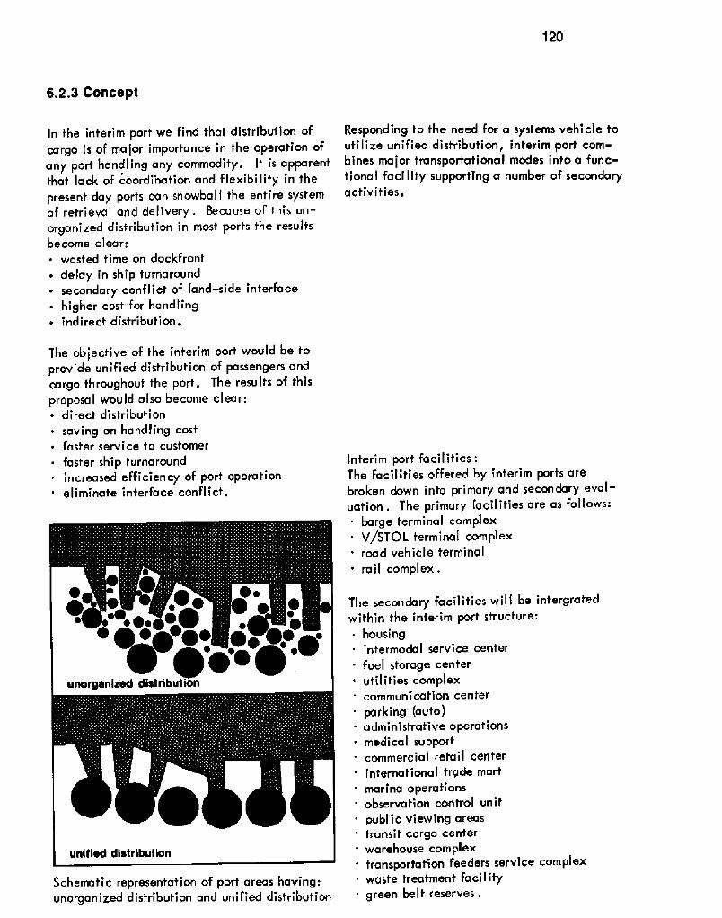
120
6.2.3 Concept
In the interim port we find that distribution ofcargo is of major importance in the operation ofany porf handling any commodity. It is apparentthat lack of coordi'nation and flexibilify in thepresent day ports can snowball the entire systemof retrieval and delivery. Because of this un-organized disfribution in most ports the resultsbecome clear;~ wasted time on dockfront
delay in ship turnaround~ secondary conflict of land-side interface~ higher cost for handling~ indirect distribution.
The objective of the interim port would be toprovide unified disfribution of passengers andcargo throughout the port. The results of thisproposal would also become clear;~ direct distribution
~ saving on handling costfaster service to customer
~ faster ship turnaround~ increased efficiency of port operation
eliminate interface conflict.
Schematic representation of port areas having..unorganized distribution and unified distribution
Responding to the need for a systems vehicle toutilize unified distribution, interim port com-bines major transportational modes into a func-tional facility supporting a number of secondaryactivities.
Interim port facilities:The facilities offered by interim ports arebroken down into primary and secondary eval-uation. The primary facilifies are as follows:
barge terminal complexV/STOL terminal complex
' road vehicle terminal' rail complex.
The secondary facilities will be intergratedwithin the interim port structure:~ housing
intermodal service center
' fuel storage centerutili ties corn pl ex
' communication center
. parking auto!administrative operationsmedical supporfcommercial refail centerinternational frgde mart
' marina operationsobservation control unitpublic viewing areastransit cargo center
' warehouse complex- transportatice feeders service complex
waste treatmenf facility. green belt reserves.

interim port hinterland structure
Plan view showing surface leve'l of interim port
Exposed interior view reveals barge and tramnfacilities first level! of interim port

122
lnferim port interface:The surface transportation network wil I consistof a central roadway traversing the aboveinterim port at the residential level .
All inbound and outbound barges wil I enterat specified levels info interim port. Specialemployee parking and traffic service laneswill be established at different levels of acti-
vity. Transit vehicles will also serve the in-terim port complex from near by metropolisareas .
Grade separation interchanges will allow un-inferrupted interface between the major trans-portational modes . Greenbel t reserves andlandscaped zones will be provided to bufferpublic usage areas from commercially un-attractive operations. Maximum usage of suchareas will establish acousfical reduction and
visual screening of interim porf services.
Vertical section through interim port showingcirculation patterns and facilities
lnf'erface in interim port will be on two levelsof importance: first is the four modes of trans-port within the port. Second, fhe operationalinterface servicing the firsf level of interface.Both these systems are inder-dependent on theother.
Phasing: Interim Port:The staging and adoption of facilities at theterminal connection would need tremendouscoordination between all persons, organizationsand governments invol ved .
Phasing could be thought of as two different ap-proaches but both very much a part of the other:~ instructive phasing~ physical phasing
The instructive or educational phasing shouldbe so designed as to educate people, the realrecipiants of fhe system, as well as ownersand operators of transportation systems peo-ple directly affected by the existence of sucha port!.

123
Educational flow for instructive phasing
The educational approach is needed for success,More thon one project has been crushed forfailure to adopt this approach. Publicity is notenough; the people must be involved, Feelingthey know what is going on as well as wantingthe project to be a success will help them knowthe benefits af the venture will be theirs.
This educational program should be carriedthroughout the entire development of interimports,After a well designed educational plan hasbeen conceived and structured the first phaseof a four phase plan could begin.
The physical phasing would begin with trans-formation of port facilities at the coastal pointsand inland points as well as the developmentof the transportation systems into a correlated'linkage matrix between interim port and thehinterland it serves.
Phase Iprocurement of rightmf~ays
' phasing out of present facilities on a tenyear program
' preparation of site area for new construction. redefinition of rail and trucking routes' temporary use of land for support facilities
pollution contracts begun.Phase 2
begin construction of linkage systems to metro-politan areas
~ establishment of alternate approach routes tosite area
~ raad and rail development near completionestablishment of greenbelt areas
' 50k total facilities near completion,Phase 3' final connection of linkage system with interim
portfull operational service to be establishedwaterborne traffic using 5' barge.
This phase is of particular importance becauseall aims of the concept should be becoming realityin the technological sense while maintaining en-vironmental integrities .
Phase 4 will be a re-evaluation of the conceptwith the establishment of objectives in relationto population growth patterns and distributionwith emphasis upon areas which shaw the greatestneed. The concept will provide a firm basis forfurther expansion of future transportational needs.
Conclusionslt is apparent that only the schematic design ofthe interim port concept has been established in 'the preceding pages, lacking dimensional characterof a finished design package. It is the aim of thisconcept to offer an option to port development;asystem, employable now, 10 years from now andin future ports of 2000 AD.
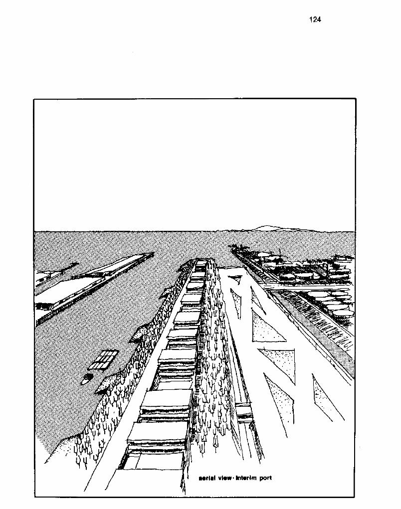
124
aerial view interim port
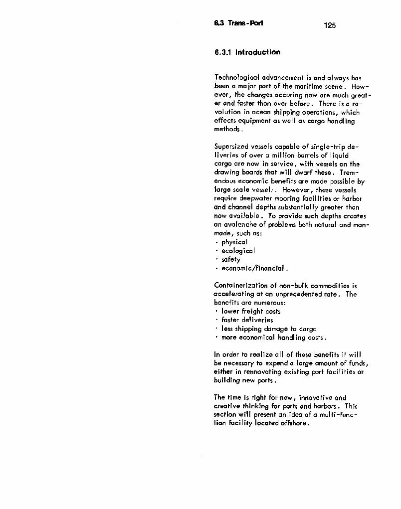
6.3 Trans-Port 125
6.3.1 introduction
Technological advancement is and always hasbeen a major port of fhe marifime scene. How-ever, the changes occuring now are much great-er and faster than ever before. There is a re-volution in ocean shipping operations, whicheffecfs equipment as wel I as cargo handlingmethods,
Supersized vessels capable of single-trip de-liveries of over a million barrels of liquidcargo are now in service, with vessels on thedrawing boards that wil I dwarf these . Trem-endous economic benefits are made possibJe bylarge scale vessel;. However, fhese vesselsrequire deepwater mooring facilities or harborand channel depths substantially greater thannow available. To provide such depths createsan avalanche of problems both natural and man-made, such as:~ physical. ecological. safety~ economic/fina n cia I .
Containerization of non-bulk commodities isaccelerafing at an unprecedented rate. Thebene fi ts are numerous:
. lower freighf costs
. faster deliveries
' less shipping damage fo cargomore economical handling costs .
In order to realize all of these benefits if will
be necessary to expend a large amount of funds,either in rennovating exisfing port facilities orbuilding new ports.
The time is right for new, innovative andcreative thinking for ports and harbors. Thissection will present an idea of a multi-func-tion facility located offshore.

126
6.3.2 Concept
Trans-Port is a facility designed to meetthe needs of an industry wifh rapid chang-ing technological advances. It is a pointof interface of transportation modes. Trans-Port becomes the common denominator foreach transportation mode,
The prime goal of each mode is to movecargo, whether it be bananas, mail orpeople, The ferminal lac ilifies wherecargo is loaded and unloaded requiresvery similar equipmenf regardless ofcarrier type .
The principal behind the Trans"Port ideais to stratify or vertically separate fhe fr<as-portation modes, In effect, separate zonesare created for each mode with a commonterminal foci'Iity .
Based on the requirement of deep waterto accommodate deep draft vessels, theTrans-Port will be located in wafer over100 feet deep,along the continental shelf,The actual site to be determined by needbased on volume of ship traffic.
Since the Trans-Port must serve the hinter-land, it is necessary to establish a directlink. There are several options avai'lable:
above surfacesurface
below surface.
By providing a submerged tunnel/tube con-necting the Trans-Port to land, it will bepossible to establish a dry connection forrail or conveyor systems. The tunnel/'tubecan be prefabricated of concrete, floatedto the site, submerged and assembled. Afterassembly the structures can be anchored fothe bottom then pumped dry. A tunnel/tubeconnection will permit continuous submergedaccess in conjunction with air and sea access.
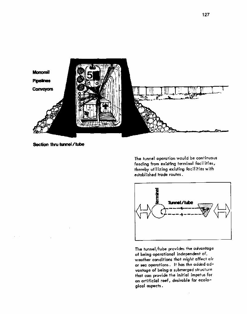
127
Section thru tunnel/tube The tunnel operation would be continuousfeeding from existing terminal facilities,thereby utilizing existing facilities withestablished trade routes.
The tunnel /tube provides the advantageof being operational independent of,weather conditions that might affect airor sea operations. If has the added ad-vantage of being a submerged structurethat can provide the initial impetus foran artificial reef, desirable for ecolo-gical aspects.

128
The need for a facility is apparent, due tothe liquid bulk cargo industry. By providinga multi-use facility the expensive cost ofconstructing such a Facility is justifiable.
The advantages are many:unlimited expansion capabilitiesfacility not dependent upon one cargotype for successeliminates noise and air pollution pro-blems from the urban areas
' inhances ship turnaround and travel timeincreases safety in navigation by elimi-na ting trea cherous channel na vigaf ion .
A study by Paul Weidlinger, consultingengineers, called FLAIR proposed a largefloating airport constructed of large modu-lar units, floated together and anchored bycables. This system when completed pro-vided a stationary platform providing twoparallel runways with necessary aircraftloading and support facilities.
Source: Architectural 8 Engineering News,December 'I 969
Plan of FLAIR

129
Applying the same technique with a 2 levelmodule, it will provide approximately50,000,000 square feet of covered spacethat can provide a year round working en-vironment for port personnel and visitors, aswell as accommodations for air travelerswith layovers.

130
With the use of conveyor systems and com-puterized coding . Storage and retrieval ofcontainers will be a simple automatic pro-cedure. Aircraft can be lowered to the portlevel to receive their cargo and returned tothe flight level for rapid delivery,
level plan, Trans- Port

UP
Interior view of container section

7 Glossary 132
Source.. Port of 4msterdom

f33
Male � a breakwater .
4 ir Rights � use of a ir space a bove .
Apron - the portion of a pier or wharf lyingbetween the waterfront edge and thetransit sheds .
Basin, Tidal � a dock or basin in which thewater level changes.
Basin, Turning � area of water set asidefor vessel turnaround.
Berth � the water area reserved for vesselsat a wharf or pier.
Breakwater - an engineering structure pro-viding shel ter from wave action .
Cofferdam � a temporary structure for theexclusion of water froim a site duringconstruction .
Crane, Gantry � a lifting device mountedon a structural frame, generally trackmounted for mobility.
Crane, Luffing - the boom can be raised orlowered without changing the heightof the load.
Dock, Dry - A! floating dry dock is a buoy-ant structure open at both ends capableof being flooded and pumped out fo faci-litate vessel entry . B! Graving DryDock - a vessel is floated in, then gatesare closed and the area pumped dry.Generally for repair or cleaning of avessel .
Dolphin � an isolated cluster of piles usedfor mooring or markers.
Dunnage � filI material placed in voids incargo holds between cargo and shipto prevent cargo movement.
DWT � dead weight tons
Fender System - protective devices to preventcontact between vessel and structures.
Iribarren Equation - determines the relation-ship between weight and slope of break-waters for different wave heights.
Mean Low Water � the average height of thelow waters determined by averaging thehourly levels over a period of time.
Mean Sea Level - the average height of thesea determined by averaging the hourlylevels over a period of time .
Overtopping � cresting of waves over the topof a breakwater.
Quay - European term for wharf.
Slip - open space of water between piers.
Stevenson Formula - developed by ThomasS te ven son to determine the a pproxima tewave height in a harbor.
Stowage - the process of placing cargo.
Terminal � the structures, facilities, or equip-ment at the end of a transportation move-ment, for the transfer of cargo .
Warp � process of turning a vessel around adol phin .
Weepholes � located in sheet piling used asa bulkhead retaining wall when the waterIevel in front of the bulkhead varies con-siderably. This equalizes some of the loadpressures caused by differences in dry andsubmerged conditions.

1348 Bibliography
8,1 Books
The American Association of Port Authorities,Inc. Handbook 1970. Washington, D.C.,1970.
Berlund, Abraham, Ocean Trans rtation.1931 .
Bird, James. The Ma'or Sea orts of the UnitedKingdom. Hutchinson of London, 'l963.
Seaport Gatewa of Australia . OxfordUniversity Press, 1968.
Borgese, Elisabeth Mann . The Ocean Regime.Center for the Study of Democratic Insti-tutions: Santa Barbara, Col ifornia,October 1968.
Bown, A.H.J,, and Dove, C.A. Port Opera-tion and Administration. Cornell Maritime
Press; Cambridge, Maryland, 1960.
Hrahtz, John . Ocean Engineering . Wil ey:New York, 'I968.
~o* ! ' . cMaritime Press: Cambridge, Maryland,1958 .
Chancy, Charles A. Marinas. NationalAssociation of Engineers and Boat Manu-facturers: New York, 1961 .
Collected Reprints ESSA Institute for Ocean-a~graph . Atlantic-Pacific OceanographicL.aboratories, U.S . Department of Com-rrterce, Environmental Science ServicesAdministration, 1966-67, � Volumes! .
Evans, J, Harvey, and Adamchak, John C.Ocean Engineering in Structures. MITPress: Cambridge, Massachusetts, 1969.
Fair, Marvin L. Port Administration in theUnited States, Cornell Maritime Press:
Gonter, Wytze. United States ShippingPolicy. Harper: New York, 1956.
Hardy, A.C. The Book oF the Ship. Thee * ill ~c. ' ', 94
Hedden, Walter P. Mission: Port Develoment ..... With Case Studies. The
American Association of Port Authorities;
Washington, D.C., 1967.
Henvelmans, Martin . Cargo DeadweightDistribution . 'I 945.
Horyle, B,S, The Seaport of East Africa.East African Publ ishing House: Na irobi,1967.
Hudson, Wiibur G. Conveyors and RelatedEquipment. J. Wiley 8 Sons, Ltd: NewYork, 1954.
Immer, John R. Container Services of fheAtlantic � 1970. Work Saving International:Washington, D,C,
Materials Handling. McGraw-Hill BookCompany; New York, 1953.
>hrbucher der Hafenbautechnischen Gesellschaft, related to Bremerhaven!. 21/21 Vol . 1950-51; 27/28 Vol . 1962-63; 30/31 Vol . 1966-68; Springer-Ver lag: Berlin .
Knauth, Arnold W. The American Law of OceanBills of Lading. American Maritime Cases,Inc: Baltimore, Maryland, 194 I .
Lederer, Eugene H. Port Terminal Operation.Cornell Maritime Press: New York, 'I 945,
McFarland, Capt. Myron E. Cargo Loss andDamage. Cornell Maritime Press: NewYork, 1942,
Marine Technolog 1970, Volumes 1 8, 2. 6th

135
Annual Conference 8 Exposition.Washington, D.C., June 29 � July 1.
Merchant Vessel Size in United States Off-shore Trades b the Year 2000. Com-mittee on Ship Channels and Harbors, TheAmerican Association of Port Authorities.June 1969.
Metcalfe, James Vernon . The Principles ofOcean Trans rtation, Simmons-BoardmanPublishing Corporation: New York, 1959.
Morgan, F .W . Ports and Ha rbors . HutchinsonUniversity Library: London, 1958.
MRIS Bulletin . Maritime Research Informa-tion Service, National Academy ofSciences-National Academy of Engineer-ing . Washington, D.C., Summer 1970.
Newan, Capt. Q.B. Marine Electric Power.1945.
O'Loughlin, Carleen. The Economics of SeaTransport. Pergamon Press: Oxford, NewYork, 1967.
Oram, Col . R,B. Cargo Handling and theModern Port. The Commonwea th andInternational Library . Pergamon Press:Oxford, New York, 1965.
Padelford, Norman J. P bl' ol'c fSeas. The MIT Press: Cambridge,Massachusetts, 1970.
Peferes, Richard J. Dakar and West AfricaEconomic Developmenf. Columbia Uni-versity Press: New York and London, 1968.
Pierce, Newton L. and Steward, John Q.Marine and Air Navigation. Ginn andCo; New York, 1944.
Port Design and Construction. The AmericanAssociation of Port Authorities. Washington,D.C., 1964.
Ports of the Americas. American Association
of Port Authorities. Washington, D.C.,l 961,
Ports of the World. Berm Brothers. Marine
Publications Limited: London, 1968.
The Ports of New South Wales. The MaritimeServices Board of New South Wales, Aus-traliaa . The Griffin Press: Adelai de, SouthAustra I ia, 1970.
Progress Into The Sea . Transactions of thepo Ocfober 'l 969!, Marine
Technology Society. Washington, D.C.,1970 .
Quinn, Alonzo De F. Design and Constructionof Ports and Marine Structures . Mc Graw-
Hill Book Company: New York, New York,1961 .
Radius, Walter A . U.S. Shipping in Trans-pacific Trade 1922-1938. GreenwoodPress: New York, 1968.
Sauerbier, Capt . Charles L ., USN R, MarineCargo Operations . 1956 .
Sibley, Marilyn McAdams, The Port ofHausfon, A History. University of TexasPress: Austin, 1968.
Stroyer, R. Concrete Structures in MarineWork. Knapp, Drewitt 8 Sons, Ltd:London 'I 949
Summeril I, John F . Tanker Manual . CornellMaritime Press: New York, 1947.
136
Wagret, Paul . Polder Lands. Methuen:London, 1968.
Wooler, R.G. Tankerman Handbook. E.W,Sweetman: New York City, 1946.
Ramsey, C.G. and Sleeper, H.R. ArchitecturalAE ~l
Wiley and Sons, Inc: New York, 1956.
8.2 Governmental Publications
Boatin Statistics 1969. Department ofTransporfation, Linlted States CoastGuard. Washingfon, D.C., 1970.
Ex rting to the United States. U,S.Department of Treasury, Bureau ofCustoms, Office of Information andPublication . Washington, D.C. 20226
fire Fighting Manual for Tank Vessels. De-partment of Transportation, United StatesCoast Guard. Washington, D.C., July1, 1968.
Harbor and Port Develo ent, A Problemand An 0 part'unit . U.S. Army Carpsof Engineers. July 1968.
Internafional Conventions and Conferences
Treasury, United States Coast Guard.Washington, D.C., June 1, 1951.
Laws Governin Marine Ins ction . Depart-ment of fhe Treasury, United Stafes CoastGuard. Washington, D.C., March 1,1965.
A Manual for the Safe Handling of Inflammableand Com usti e Liquids. Treasury Depart-ment, Un!fed States Coast Guard. Washington,D.C., March 2, 1964.
Panel Reports of the Commission on MarineScience, Engineering and Resources � Volumes1-3: Science and Environment, Industr andTechnolog, Marine Resources and Legal�Po itica Arrangemenfs for Their Development.U.S. Government Printing Office; Washington,D.C., 1969.
Port Aransas � Corpus Christi Waterwa, Texas.! .
District, Corps of Engineers. Galveston,Texas.

137
Rules and Re ulations for Artificial Islands
and Fixed Structures on the Outer Con-
tinental Shelf. Department of Trans-portation, United States Coast Guard.Washington, D.C., November I, 1968.
Rules and Regulations for Cargo and Miscel�laneous Vessels, Subcha pter I . Depart-ment of Transportation, U.S. CoastGuard. U.S . Government PrintingOffice: Washington, D.C., 1969.
Rules and Re ulations for Marine En ineeringInstallations Contracted for Prior to Jul
1 1 935 r Treasury Department, U, SCoast Guard. U.S. Government PrintingOffice. Washington, D.C,, 1953.
Rules and Regulations For Militar Explosivesand Hazardous Munitions. Department ofTransportation, United States Coast Guard.Washington, D.C., May I, 1968.
Rules and Regulations for Passenger Vessels,
tion. U.S. Government Printing Office:Washington, D.C., 1969.
Rules and Regulations for Small PassengerVessels, Subcha ter T. Department ofTransportation, U.S. Coast Guard. U.S .Government Printing Office: Washington,D,C., 1969.
Rules an d Regulations for Tank Vessel s, Sub-chapter D. Department of Transportation,U.S. Coast Guard. U.S. Government
Printing Office: Washington, D.C,, I 969.
Rules of the Road International � Inland! . De-partment of the Treasury, United StatesCoast Guard. Washington, D,C., Septem-ber 1, 1965 .
Texas Motor Vehicle Laws . Commercial Ve-
hicle Registration Data. Austin, Texas.
Transportation af Oil . Petroleum Administrationfor Defense. U,S. Government PrintingOffice: Washington, D . C ., December I 951 .
University Curricula in the Marine Sciences andRelated Fields. Nationa! Council an Marine
Resources and Engineering Development . U.S .Government Printing Office: Washington,D.C., Academic Years 1969-70 and 1970-71.
138
8.3 Reports
San Francisco, 1969.Annual Report, Pacific Maritime Association,
Berg, Ernest Koenigs, et al, TransoceanTug-Barge S stems, A Concepfual Study.Vol . 1, Vol . 2, Vol . 3, Matson ResearchCor po ra tion . San Franc i sco, Ca I i fornia gJuly 1970.
Cargo Ship Loacfing, An Analysis of GeneralCargo Loading in Selected U.S, Ports.National Academy of Science .
Containerization in Marifime Transportationof General Cargo . National ResearchCouncil, Maritime Cargo TransportationConference, 1957,
D/FW 2001, Dallas/Fort Worth Regional Air-part � 2001 . Stanko Hommel, WankWilliams and Neylan, Inc.
Deep Sea and Coastwise Longshore and CottonAgreemenf. Texas Ports, and Port of LakeCharles, Louisiana.
Feasibility Study for an Oceanographic In-dustria Park and Seaport. Bec te Cor-poration, September 'l 968.
Intermoda I Transporfa tion . Brochure fromCentral Gulf Lines.
Marine. Brown 8, Root, Incorporated.Houston, Texas.
Marine Affairs in Texas, A Report for 1968-69. Texas A8M University Sea GrantProgram . December 1969, PublicationNo. 103,
Marine Resources Activities in Texas, Pre-pared for the National Science Foundation'sSea Grant Program of Texas AB,M University,Texas Engineering Experiment Station, TexasAIM University. August 1969.
Maritime Research and Development. Re-port of the Woods Hole Conference, WoodsHole, Massachusetts, July 7-24, 1969.U.S. Department of Commerce, MaritimeAdministration .
Masterplan for Long-Range Development ofthe Porf of New Orleans. Bechtel Cor-
poration, March 1970.
Miloy, John and Copp, E. Anthony. EconomicImpact Analysis of Texas Marine Resourcesand Industries. Industria Economics Re-
search Division, Texas Engineering Experi-ment Station, Texas ASM University SeaGrant Program. June 1970,
Modular Design Applications Stud Deckhouseand Outfit! . J,J. Henry Co., Inc.,Naval Architects and Marine Engineers.U.S. Department of Commerce, MaritimeAdministration .
National Ports Council � Annual Report andStatement of Accounts December 31, 1969!.Her Majesty's Stationery Office. London,England .
National Ports Council � Research and Tech-
nical Bulletin Number 6, 1970. NationalPorts Council, May 'l970,
Oceanborne Shipping: Demand and TechnologForecast Parts 1 and 2. Litton Systems,Incorporated. Culver City, California,June '1968 .
The Ports and Waterways View, Texas MarineResources . Texas AB,M University SeaGrant Program, College Station, Texas,1970.
Port Progress Report 1969, National Ports Coun-cil, London, England. A. McLay and Com-pany, Limited: Fairwater, Cardiff, England.

139
8.4 Articles
Port Progress Re rt - Summar
Beaumont, The Port Commission,Beaumont, Texas, March 1, 1967.
Re rt of the Committee of l ui into theMa'or Ports of Great Britain. Ministryof Transport, London . Her Ma jesty'sStationery Office: 1967.
Re rt of Sea Grant Project Activities'l 968-69. Texas A8 M University SeaGrant Program, December 1969, Pub-lication Na. 104.
R.
Harris, inc: New York, New York,i 970,
Agatz, A. and Lutz, R. SeeverkehrswasserbauSpringer-Verlag, Berlin. Heidelberg,1955 .
"Government Floated in Water," Ekistics.January 1968.
Gregory, Lloyd. "Alamo Barge Lines HeadSold on Water Transport," Port of Houston~tria azine. Ctctoher 1970.
Gull ion, Edmund A . "Uses of the Seas,"American Assembl Publication . 1968.
"lnnerspace," A D Architectural Design! .7/6, Vol. XXXlX, April 1969.
"investors go t'o Sea," Business Week. August31, 1968.
Lear, John. "The Pulse of the Earth; Ex-piorintt the Air, Water, Sea," ~SaturdoReview . February 1, 1969.
Lutz, Dr. lng. Ralph. "The Docks af the FreeHanse Town of Bremen," The Dock and
*
Marshall, Kenneth. "The Supplementas: FastComers in Air Transportation," ~Trans rta-tion and Distribution Management. Novem-ber 1969.
"The Ocean," Scientific Amer1can . September1969, Vol . 221, No. 3.
"The Ocean Comes to Oklahoma," ReadersDigest . November 1970.
"Ocean is Expansive Oil Field," ScienceNews. May 14, 1966.
"Probing Ocean Shallows," Science News.March 23, 1968.
"Science from a Habitat," Science News.November 8, 1969.
"A Taxi for the Deep Frontier," National~Geogra hie. January 1968.

'140
8.5 Papers
1970.
Grant Program.
"Transportation Telephone Tickler," TheJournal of Commerce. Port of Houston,Houston, Texas, Twin Coast Newspapers,Inc: New York; August, 1970.
"Under Sea Transit," AD ArchitecturalDesign! . May 197K
"Urban Expansion Takes to the Water,"Fortune . September 1969,
"Waste Management Systems," Ekistics .November 1968.
"Working for Weeks on the Sea Floor,"National Geogra hic . April 1966.
Clark, Brigadier General Allen F. Thet fl V IS
Glickman, David L. Port Problems and
on Maritime Research and Development,xel ox ~
Juichi Kata. Status of Floating BreakwaterR h A 0 fJa
Kneiling, John G. P. E. A Modern inward*' '» I~I
Veraa, Claude F. Proposed AquaculturatProgram. Marine Tec no ogy, 196,reprint .
