port flow simulation of an ic engine - ijiert.org 2 issue... · the internal combustion engine...
TRANSCRIPT

NOVATEUR PUBLICATIONS
INTERNATIONAL JOURNAL OF INNOVATIONS IN ENGINEERING RESEARCH AND TECHNOLOGY [IJIERT]
ISSN: 2394-3696 VOLUME 2, ISSUE 9, SEP.-2015
1 | P a g e
PORT FLOW SIMULATION OF AN IC ENGINE
Himanth Kumar H Y,
PG Student
Department of Mechanical Engineering,
Vidyavardhaka College of Engineering, Mysuru, India
Jayashankar N
Associate professor,
Mechanical department,
Vidyavardhaka College of Engineering, Mysuru, India
ABSTRACT
This paper deals with the numerical analysis of 3d model which has inlet port diameter 46mm, valve
diameter 43mm and the length and diameter of the cylinder is 562mm and 93.65mm respectively
which is developed to study the effect of valve lift on the flow of fluid inside the cylinder. For
different valve lifts velocity will change inside the cylinder. Results of CFD simulation indicated that
valve lift affects velocity flow field inside the cylinder. It also proved that CFD is a convenient tool
for designing and optimizing the flow field in the engine.
KEYWORDS-Computational fluid dynamics; intake manifold; inlet port; Numerical simulation;
INTRODUCTION
The internal combustion engine usually consists of four cycles such as intake, compression,
expansion (including combustion) and exhaust. Out of these four processes intake and compression
strokes are most important as these strokes influences the pattern of air flow coming inside cylinder
during intake stroke and it generates the condition needed for the fuel injection during compression
stroke. For maximizing the air passing into the cylinder manifold design has to be optimized. Hence
design of intake manifold is more important in engine design. Experimental methods would cost time
and money to achieve this. Using CFD tool without undergoing any time consuming experiment
engine efficiency can be estimated.
Short discussions of the previous studies of authors are presented here. Chen et.al [1] gives result of
fluid flow through an IC engine inlet port both in experimental and computational mode. The port
was straight generic inlet port. They used CFD tool to analyze the velocity contours near port region.
They have used LDA and LSFV technique to analyze fluid flow. Both experimental and prediction
results shows that the valve lift that affect the flow Robert et.al [2] studied the two common motions
in an automobile engine they are tumble and swirl motion using visualization techniques. Benny et.al
[3] investigates the effect of helical, spiral manifold configuration on air motion in a diesel engine.
Using CFD tool flow patterns of these different manifold configurations are studied. The CFD results
of swirl velocity inside combustion chamber are compared with experimental results.

INTERNATIONAL JOURNAL OF INNOVATIONS IN ENGINEERING RESEARCH AND TECHNOLOGY [IJIERT]
Prasad.et.al [4] investigates the swirl air created due to injecting air into the manifold. To direct air
flow into the inlet manifold they have grooved the inlet manifold with helical groove to create
turbulence in the manifold. The tests are conducted by va
maintained constant.
The main objective of this proje
intake manifold, inlet port and valve
enhances the performance of the engine by improving combustion rate
II MATHEMATICAL FORMULATION
2.1 The physical model and coordinate system
A 3D model of a inlet port and valve with cylinder is s
(Ver. 14.5).
Table 2.1 Dimension
Diameter of
Diameter of the valve
Diameter of the cylinder
Length of the
Valve lift
Fig 2.1 Theoretical model
MESHING
� The model is created using ANSYS FLUENT
� In-cylinder problems solved in Fluent consist of three stages
geometry into different zones and mesh them properly.
� The second stage is to set up the engine case inside Fluent with the help of a setup journal.
� The third stage is to perform a transient in
INTERNATIONAL JOURNAL OF INNOVATIONS IN ENGINEERING RESEARCH AND TECHNOLOGY [IJIERT]
VOLUME 2, ISSUE 9, SEP.
sad.et.al [4] investigates the swirl air created due to injecting air into the manifold. To direct air
flow into the inlet manifold they have grooved the inlet manifold with helical groove to create
turbulence in the manifold. The tests are conducted by varying dimensions of groove and speed was
The main objective of this project is to analyze the velocity characteristics of fluid flow through the
intake manifold, inlet port and valve to get optimized swirl and tumble motion, so that one can
enhances the performance of the engine by improving combustion rate.
II MATHEMATICAL FORMULATION
2.1 The physical model and coordinate system
inlet port and valve with cylinder is shown in fig is created in
Table 2.1 Dimensions of various parts of model as shown in Fig 2.1
inlet and outlet port 46 & 39.5 mm
iameter of the valve 43 mm
ameter of the cylinder 93.65 mm
Length of the cylinder 562 mm
Valve lift 10 mm
Theoretical model Geometry model created in fluent
model is created using ANSYS FLUENT software.
solved in Fluent consist of three stages. The first stage is to decompose the
geometry into different zones and mesh them properly.
The second stage is to set up the engine case inside Fluent with the help of a setup journal.
The third stage is to perform a transient in-cylinder simulation.
NOVATEUR PUBLICATIONS
INTERNATIONAL JOURNAL OF INNOVATIONS IN ENGINEERING RESEARCH AND TECHNOLOGY [IJIERT]
ISSN: 2394-3696 VOLUME 2, ISSUE 9, SEP.-2015
2 | P a g e
sad.et.al [4] investigates the swirl air created due to injecting air into the manifold. To direct air
flow into the inlet manifold they have grooved the inlet manifold with helical groove to create
rying dimensions of groove and speed was
ct is to analyze the velocity characteristics of fluid flow through the
to get optimized swirl and tumble motion, so that one can
is created in ANSYS FLUENT
shown in Fig 2.1
& 39.5 mm
93.65 mm
562 mm
Geometry model created in fluent
first stage is to decompose the
The second stage is to set up the engine case inside Fluent with the help of a setup journal.

NOVATEUR PUBLICATIONS
INTERNATIONAL JOURNAL OF INNOVATIONS IN ENGINEERING RESEARCH AND TECHNOLOGY [IJIERT]
ISSN: 2394-3696 VOLUME 2, ISSUE 9, SEP.-2015
3 | P a g e
� First, the surface is meshed with triangular element. In order to resolve the turbulent boundary layer
on the solid surfaces, it is best to have growing prismatic cells from the Valve surfaces. Finally the
remaining region in the domain is filled with tetrahedral cells. No of elements is used for mesh
generation is 11 to 12 lakhs approximately.
� The domain has been subdivided into growing boxes to make it easier to generate the grid. The choice
for the elements has been both tetrahedral and hexahedral mesh volumes.
Fig 3.1 Meshed model in FLUENT
GOVERNING EQUATIONS
There are mainly three equations we solve in computational fluid dynamics problem. They are
Continuity equation, Momentum equation (Navier Stokes equation) and Energy equation.
4.1.1 Continuity Equation
A continuity equation expresses a conservation law by “Equating a net flux over a surface with a loss
or gain of material within the surface”. Continuity equations often can be expressed in either integral
or differential form as shown below.
0=∂
∂+ ∫∫
cvcs
dAt
dAV ρρ
This is a statement of the principle of mass conservation for a steady, one-dimensional flow, with one
inlet and one outlet.
( ) 0=∂
∂+∇
tV
ρρ

NOVATEUR PUBLICATIONS
INTERNATIONAL JOURNAL OF INNOVATIONS IN ENGINEERING RESEARCH AND TECHNOLOGY [IJIERT]
ISSN: 2394-3696 VOLUME 2, ISSUE 9, SEP.-2015
4 | P a g e
Where, ^^^
kz
jy
ix ∂
∂+
∂
∂+
∂
∂=∇
∂ρ∂t +
∂(ρ. u)∂x + ∂(ρ. v)
∂y + ∂(ρ. w)∂z = 0
4.1.2 Momentum (Navier Stokes) Equations
The momentum equation is a statement of Newton's Second Law and relates the sum of the forces
acting on an element of fluid to its acceleration or rate of change of momentum. The Newton’s
second law of motion F = ma forms the basis of the momentum equation.
ρ ∂u∂t + ρu ∂u∂x + ρv ∂u∂y + ρw∂u∂z = ρg� − ∂p
∂x + μ∂�u∂x� + μ∂�u∂y� + μ∂�u∂z�
ρ ∂v∂t + ρu ∂v∂x + ρv ∂v∂y + ρw∂v∂z = ρg� − ∂p
∂y + μ ∂�v∂x� + μ ∂�v∂y� + μ∂�v∂z�
ρ ∂w∂t + ρu ∂w∂x + ρv∂w∂y + ρw∂w∂z = ρg� − ∂p
∂z + μ∂�w∂x� + μ∂�w∂y� + μ∂�w∂z�
4.1.3 Energy Equation
This equation demonstrates that, per unit volume, the change in energy of the fluid moving through a
control volume is equal to the rate of heat transferred into the control volume plus the rate of work
done by surface forces plus the rate of work done by gravity
∂∂t �ρe +
12 ρv�� +
∂∂x �ρue +
12ρuv�� +
∂∂y �ρve +
12ρvv�� +
∂∂z �ρwe +
12ρwv�� =
k �∂�T∂x� +∂�T∂y� +
∂�T∂xz� − �u ∂p∂x + v∂p∂y + w∂p
∂z� +
μ !u ∂�u∂x� +∂∂x �v
∂v∂x + w∂w
∂x� + v∂�u∂y� +∂∂y �u
∂u∂y + w∂w
∂y� + w∂�u∂z� +
∂∂z �u
∂u∂z + v∂v∂z�"
+2μ !∂�u∂x� +∂u∂y
∂v∂x +
∂�v∂y� +
∂v∂z
∂w∂y +
∂�w∂z� +
∂w∂x
∂u∂z" + ρug� + ρvg� + ρwg�
BOUNDARY CONDITIONS In this simulation Pressure inlet boundary conditions are used to define the fluid pressure at flow
inlets, along with all other scalar properties of the flow. They are suitable for both incompressible and
compressible flow calculations. Pressure inlet boundary conditions can be used when the inlet
pressure is known but the flow rate and/or velocity is not known.
INTERNATIONAL JOURNAL OF INNOVATIONS IN ENGINEERING RESEARCH AND TECHNOLOGY [IJIERT]
Figure.5.
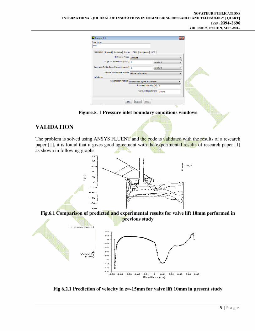
VALIDATION
The problem is solved using ANSYS FLUENT
paper [1], it is found that it gives good agreement with the experimental results of research paper
as shown in following graphs.
Fig.6.1 Comparison of predicted and experimental results for valve lift 10mm performed in
Fig 6.2.1 Prediction of velocity in z=
INTERNATIONAL JOURNAL OF INNOVATIONS IN ENGINEERING RESEARCH AND TECHNOLOGY [IJIERT]
VOLUME 2, ISSUE 9, SEP.
Figure.5. 1 Pressure inlet boundary conditions windows
oblem is solved using ANSYS FLUENT and the code is validated with the results of a
gives good agreement with the experimental results of research paper
as shown in following graphs.
Comparison of predicted and experimental results for valve lift 10mm performed in
previous study
1 Prediction of velocity in z=-15mm for valve lift 10mm in present study
NOVATEUR PUBLICATIONS
INTERNATIONAL JOURNAL OF INNOVATIONS IN ENGINEERING RESEARCH AND TECHNOLOGY [IJIERT]
ISSN: 2394-3696 VOLUME 2, ISSUE 9, SEP.-2015
5 | P a g e
Pressure inlet boundary conditions windows
the code is validated with the results of a research
gives good agreement with the experimental results of research paper [1]
Comparison of predicted and experimental results for valve lift 10mm performed in
in present study
INTERNATIONAL JOURNAL OF INNOVATIONS IN ENGINEERING RESEARCH AND TECHNOLOGY [IJIERT]
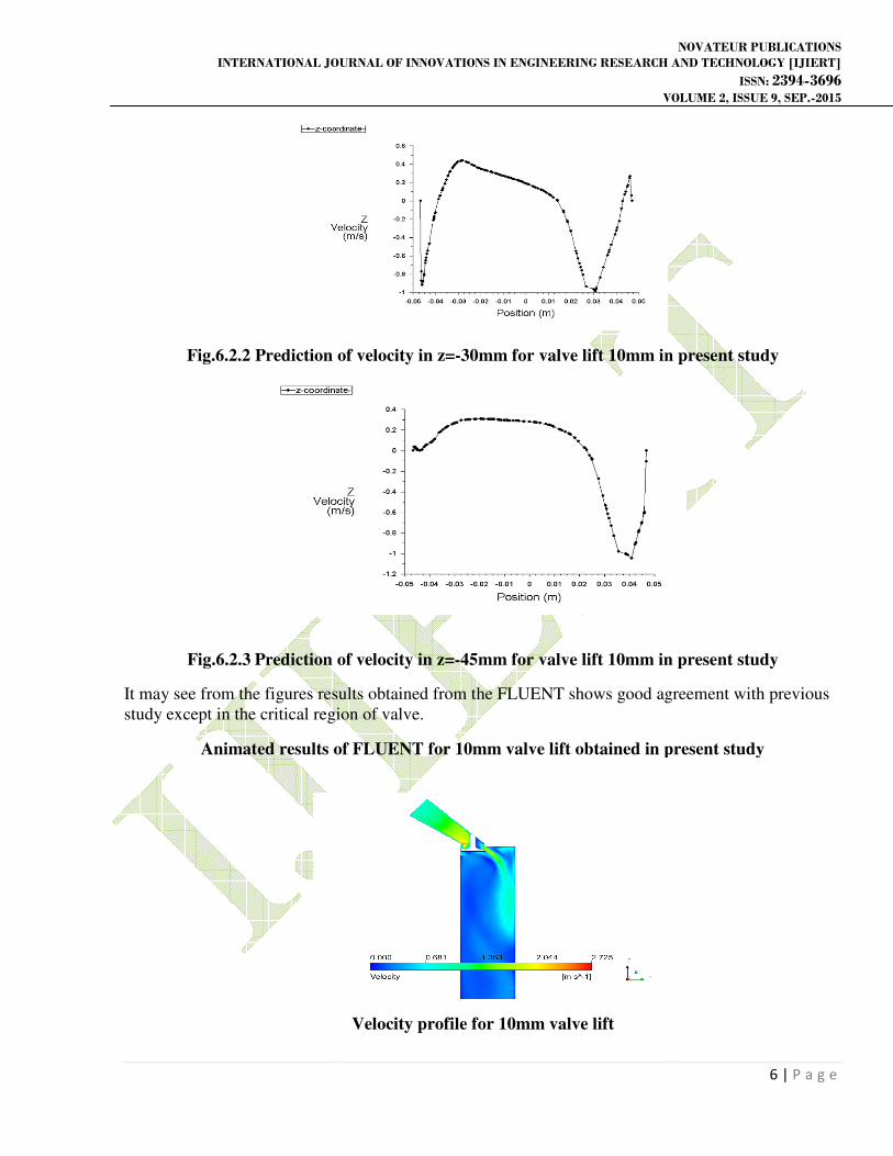
Fig.6.2.2 Prediction of velocity in z=
Fig.6.2.3 Prediction of velocity in z=
It may see from the figures results obtained from the FLUENT shows good agreement with previous
study except in the critical region of valve.
Animated results of FLUENT
INTERNATIONAL JOURNAL OF INNOVATIONS IN ENGINEERING RESEARCH AND TECHNOLOGY [IJIERT]
VOLUME 2, ISSUE 9, SEP.
Prediction of velocity in z=-30mm for valve lift 10mm in present study
Prediction of velocity in z=-45mm for valve lift 10mm in present study
from the figures results obtained from the FLUENT shows good agreement with previous
critical region of valve.
Animated results of FLUENT for 10mm valve lift obtained in present study
Velocity profile for 10mm valve lift
NOVATEUR PUBLICATIONS
INTERNATIONAL JOURNAL OF INNOVATIONS IN ENGINEERING RESEARCH AND TECHNOLOGY [IJIERT]
ISSN: 2394-3696 VOLUME 2, ISSUE 9, SEP.-2015
6 | P a g e
in present study
in present study
from the figures results obtained from the FLUENT shows good agreement with previous
for 10mm valve lift obtained in present study

NOVATEUR PUBLICATIONS
INTERNATIONAL JOURNAL OF INNOVATIONS IN ENGINEERING RESEARCH AND TECHNOLOGY [IJIERT]
ISSN: 2394-3696 VOLUME 2, ISSUE 9, SEP.-2015
7 | P a g e
Velocity profile for 10mm valve lift
Velocity streamline for 10mm valve lift
Turbulent kinetic energy profile for 10mm valve lift

NOVATEUR PUBLICATIONS
INTERNATIONAL JOURNAL OF INNOVATIONS IN ENGINEERING RESEARCH AND TECHNOLOGY [IJIERT]
ISSN: 2394-3696 VOLUME 2, ISSUE 9, SEP.-2015
8 | P a g e
Pressure profile for 10mm valve lift
Velocity contour profile for 10mm valve lift
CONCLUSIONS
To make combustion to happen air flow inside intake port plays a vital role. To get good engine
efficiency with lower emission we need to study the flow inside the intake port, manifold through the
valve. In this thesis we understand the flow characteristics through port inside the engine with the
help of CFD tool FLUENT.
CFD helps to understand the flow field inside the cylinder and also gives depth knowledge of flow in
graphical mode where measurements are not easy to make.
1. Three-dimensional modeling of intake manifold, port and valve are key factors to predict the velocity
contours inside the engine cylinder. From this thesis we can conclude that valve lift affect the flow
except region near the port bend upstream.
2. As the valve lift increases flow separation becomes critical because as valve lift increases losses near
the valve increases.

NOVATEUR PUBLICATIONS
INTERNATIONAL JOURNAL OF INNOVATIONS IN ENGINEERING RESEARCH AND TECHNOLOGY [IJIERT]
ISSN: 2394-3696 VOLUME 2, ISSUE 9, SEP.-2015
9 | P a g e
3. The results obtained from prediction shows good agreement with the experimental results except
some critical region near the valve.
REFERENCES
1. Chen, A., Lee, K.C., Yianneskis, M., and Ganti, G., Velocity Charac- teristics of Steady Flow
Through a Straight Generic Inlet Port, Interna- tional Journal for Numerical Methods in Fluids,
21:571,590, 1995
2. Robert S. Laramee , Daniel Weiskopf , Jürgen Schneider , Avl Graz , Helwig Hauser, Investigating
Swirl and Tumble Flow with a Comparison of Visualization Techniques, In Proceedings IEEE
Visualization, 2004.
3. S. L. V. Prasad, V. Pandurangadu, V. V. Prathibha bharathi and V. V. Naga deepthi, Experimental
study of the effect of air swirl in Intake manifold on diesel engine performance
4. N.Kumar.et.al "Studies on variable swirl intake system for DI diesel engine using CFD", ISSN 0973-
4562 volume 2, number 3 (2007)
5. Soonseong Hong, Byungkeunoh and Yongtae Kim, "Optimization of intake manifold design using
design for six sigma, SAE, 2007-01-3534
6. Mike Dong, Grant Chen, Min Xu and Chao Daniels, “P