portable ultrasonic flow measurement of liquids · · 2018-01-03fluxus f601 supported by handle...
TRANSCRIPT

Technical specification
FLUXUS® F601
TSFLUXUS_F601V2-1-2US_Lus, 2017-05-23 1
FLUXUS F601 supported by handle
Measurement with transducers mounted with mounting frames and flow transmitter fixed to the pipe with the Quick-Fix pipe mounting fixture
Measurement equipment in transport case
Portable ultrasonic flow measurement of liquids
Portable instrument for non-invasive, quick ultrasonic flow measurement with clamp-on technology for all types of piping
Features
• Precise bi-directional and highly dynamic flow measure-ment with the non-intrusive clamp-on technology
• High precision at fast and slow flow rates, high tem-perature and zero point stability
• Portable, easy-to-use flow transmitter with 2 flow chan-nels, multiple inputs/outputs, an integrated data logger with a serial interface
• Water and dust-tight (NEMA 4); resistant against oil, many liquids and dirt
• Li-Ion battery provides up to 25 hours of measurement operation
• Automatic loading of calibration data and transducer detection for a fast and easy set-up (less than 5 min), providing precise and long-term stable results
• User-friendly design
• Transducers available for a wide range of inner pipe di-ameters and fluid temperatures ( )
• Probe for wall thickness measurement available
• Robust, water-tight (NEMA 4) transport case with com-prehensive accessories
• HybridTrek automatically switches between transit time and NoiseTrek mode of measurement when high partic-ulate flows are encountered
• QuickFix for fast mounting of the flow transmitter in diffi-cult conditions
• Measurement is unaffected by fluid density, viscosity and solid content (max. 10 % of volume)
Applications
Designed for the following industries:
• Chemical industry
• Water and wastewater industry
• Oil and gas industry
• Cooling systems and air conditioners
• Facility management
• Aviation industry
-274 to +1112 °F

FLUXUS® F601 Technical specification
Table of contents
TSFLUXUS_F601V2-1-2US_Lus, 2017-05-232
Function ........................................................................................................................................................... 3Measurement principle...................................................................................................................................... 3Calculation of volumetric flow rate .................................................................................................................... 3Number of sound paths..................................................................................................................................... 4Typical measurement setup .............................................................................................................................. 5
Flow transmitter .............................................................................................................................................. 6Technical data................................................................................................................................................... 6Dimensions ....................................................................................................................................................... 8Standard scope of supply.................................................................................................................................. 9Connection of adapters ................................................................................................................................... 10Example for the equipment of a transport case .............................................................................................. 11
Transducers................................................................................................................................................... 12Transducer selection....................................................................................................................................... 12Transducer order code.................................................................................................................................... 13Technical data................................................................................................................................................. 14
Transducer mounting fixture ....................................................................................................................... 17
Coupling materials for transducers ............................................................................................................ 21
Connection systems ..................................................................................................................................... 22Transducer cable ............................................................................................................................................ 22
Clamp-on temperature probe (optional) ..................................................................................................... 23
Wall thickness measurement (optional) ..................................................................................................... 25

TSFLUXUS_F601V2-1-2US_Lus, 2017-05-23 3
Technical specification FLUXUS® F601
Function
Measurement principle
Transit time difference principle
In order to measure the flow of a fluid in a pipe, ultrasonic signals are used, employing the transit time differ-ence principle. Ultrasonic signals are emitted by a transducer installed on the pipe and received by a secondtransducer. These signals are emitted alternately in the flow direction and against it.
As the fluid in which the signals propagate is flowing, the transit time of the ultrasonic signals in the flow direc-tion is shorter than against the flow direction.
The transit time difference, ∆t, is measured and allows the flowmeter to determine the average flow velocityalong the propagation path of the ultrasonic signals. A flow profile correction is then performed in order to ob-tain the area averaged flow velocity, which is proportional to the volumetric flow rate.
Two integrated microprocessors control the entire measuring process. This allows the flowmeter to removedisturbance signals, and to check each received ultrasonic wave for its validity which reduces noise.
HybridTrek
If the gaseous or solid content in the fluid increases occasionally during measurement, a measurement withthe transit time difference principle is no longer possible. NoiseTrek mode will then be selected by the flowme-ter. This measurement method allows the flowmeter to achieve a stable measurement even with high gas-eous or solid content.
The transmitter can switch automatically between transit time and NoiseTrek mode without any changes tothe measurement setup.
Calculation of volumetric flow rate
= kRe . A . ka . ∆t/(2 . tfl)
where
Path of the ultrasonic signal Transit time difference ∆t
= volumetric flow ratekRe = fluid mechanics calibration factorA = cross-sectional pipe areaka = acoustical calibration factor∆t = transit time differencetfl = transit time in the fluid
V·
V·

4 TSFLUXUS_F601V2-1-2US_Lus, 2017-05-23
FLUXUS® F601 Technical specification
Number of sound paths
The number of sound paths is the number of transits of the ultrasonic signal through the fluid in the pipe. De-pending on the number of sound paths, the following methods of installation exist:
• reflect arrangementThe number of sound paths is even. Both of the transducers are mounted on the same side of the pipe. Correct positioning of the transducers is easier.
• diagonal arrangementThe number of sound paths is odd. Both of the transducers are mounted on opposite sides of the pipe.
• direct modeDiagonal arrangement with 1 sound path. This should be used in the case of a high signal attenuation by the fluid, pipe or coatings.
The preferred method of installation depends on the application. While increasing the number of sound pathsincreases the accuracy of the measurement, signal attenuation increases as well. The optimum number ofsound paths for the parameters of the application will be determined automatically by the transmitter.
As the transducers can be mounted with the transducer mounting fixture in reflect arrangement or diagonal ar-rangement, the number of sound paths can be adjusted optimally for the application..
a = transducer distance
Reflect arrangement, number of sound paths: 2
Diagonal arrangement, number of sound paths: 3
Direct mode, number of sound paths: 1 Direct mode, number of sound paths: 1,negative transducer distance
a
a
a > 0 a < 0
TSFLUXUS_F601V2-1-2US_Lus, 2017-05-23 5
Technical specification FLUXUS® F601
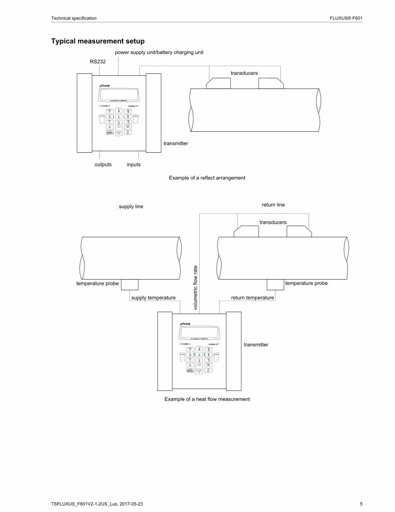
Typical measurement setup
Example of a reflect arrangement
Example of a heat flow measurement
!
" # " $ %
transducers
transmitter
RS232
outputs inputs
power supply unit/battery charging unit
!
" # " $ %
transducers
transmitter
temperature probetemperature probe
supply line return line
volu
met
ric fl
ow r
ate
supply temperature return temperature
6 TSFLUXUS_F601V2-1-2US_Lus, 2017-05-23
FLUXUS® F601 Technical specification
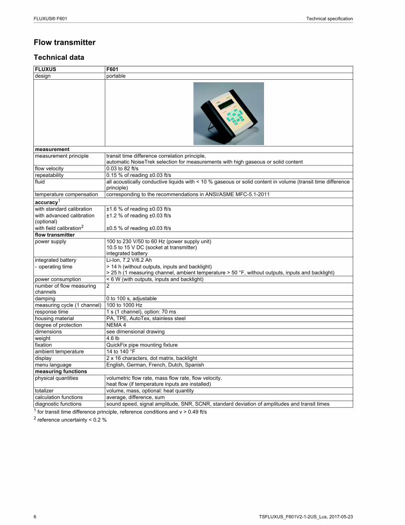
Flow transmitter
Technical data
FLUXUS F601design portable
measurementmeasurement principle transit time difference correlation principle,
automatic NoiseTrek selection for measurements with high gaseous or solid contentflow velocity 0.03 to 82 ft/srepeatability 0.15 % of reading ±0.03 ft/sfluid all acoustically conductive liquids with < 10 % gaseous or solid content in volume (transit time difference
principle)temperature compensation corresponding to the recommendations in ANSI/ASME MFC-5.1-2011
accuracy1
with standard calibration ±1.6 % of reading ±0.03 ft/swith advanced calibration (optional)
±1.2 % of reading ±0.03 ft/s
with field calibration2 ±0.5 % of reading ±0.03 ft/sflow transmitterpower supply 100 to 230 V/50 to 60 Hz (power supply unit)
10.5 to 15 V DC (socket at transmitter)integrated battery
integrated battery Li-Ion, 7.2 V/6.2 Ah- operating time > 14 h (without outputs, inputs and backlight)
> 25 h (1 measuring channel, ambient temperature > 50 °F, without outputs, inputs and backlight)power consumption < 6 W (with outputs, inputs and backlight)number of flow measuring channels
2
damping 0 to 100 s, adjustablemeasuring cycle (1 channel) 100 to 1000 Hzresponse time 1 s (1 channel), option: 70 mshousing material PA, TPE, AutoTex, stainless steeldegree of protection NEMA 4dimensions see dimensional drawingweight 4.6 lbfixation QuickFix pipe mounting fixtureambient temperature 14 to 140 °Fdisplay 2 x 16 characters, dot matrix, backlightmenu language English, German, French, Dutch, Spanishmeasuring functionsphysical quantities volumetric flow rate, mass flow rate, flow velocity,
heat flow (if temperature inputs are installed)totalizer volume, mass, optional: heat quantitycalculation functions average, difference, sumdiagnostic functions sound speed, signal amplitude, SNR, SCNR, standard deviation of amplitudes and transit times
1 for transit time difference principle, reference conditions and v > 0.49 ft/s2 reference uncertainty < 0.2 %
TSFLUXUS_F601V2-1-2US_Lus, 2017-05-23 7
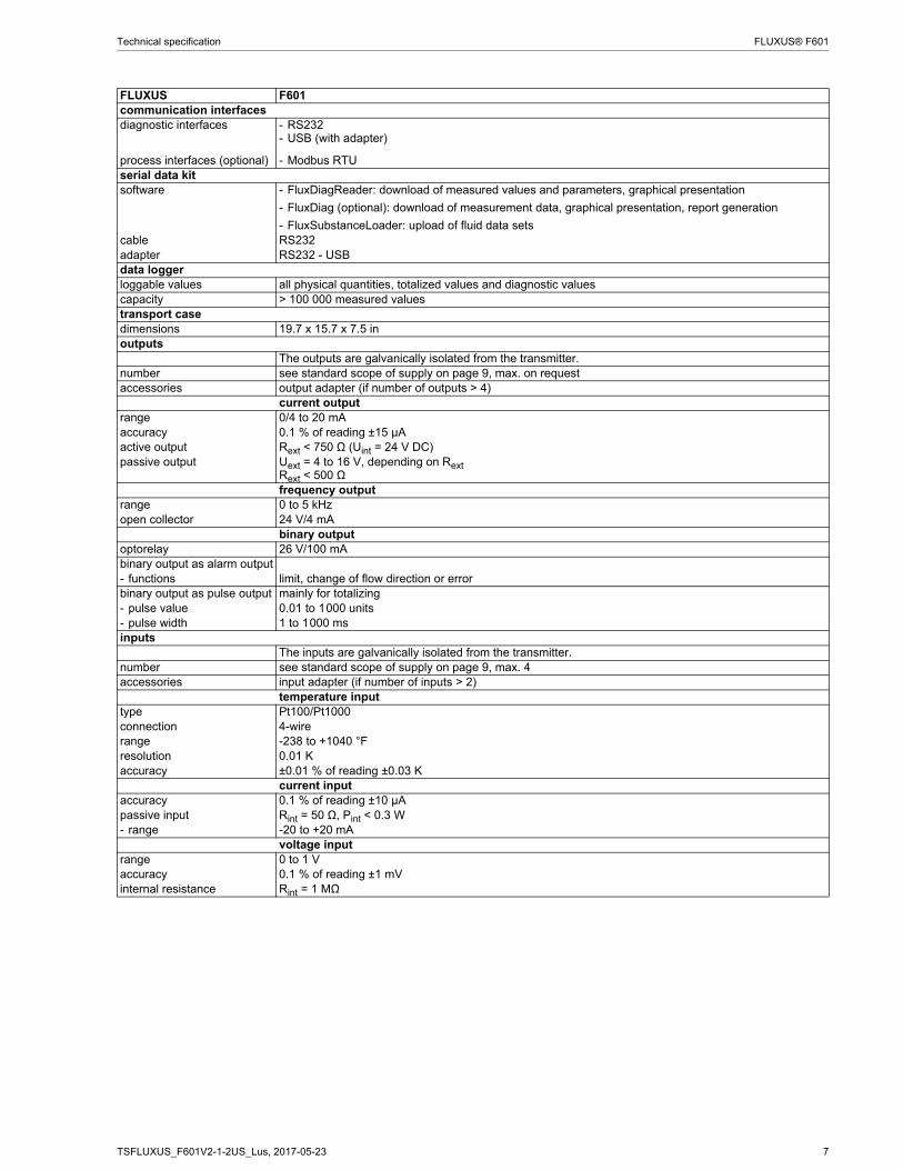
Technical specification FLUXUS® F601
communication interfacesdiagnostic interfaces - RS232
- USB (with adapter)
process interfaces (optional) - Modbus RTUserial data kitsoftware - FluxDiagReader: download of measured values and parameters, graphical presentation
- FluxDiag (optional): download of measurement data, graphical presentation, report generation
- FluxSubstanceLoader: upload of fluid data setsсable RS232adapter RS232 - USBdata loggerloggable values all physical quantities, totalized values and diagnostic valuescapacity > 100 000 measured valuestransport casedimensions 19.7 x 15.7 x 7.5 inoutputs
The outputs are galvanically isolated from the transmitter.number see standard scope of supply on page 9, max. on requestaccessories output adapter (if number of outputs > 4)
current outputrange 0/4 to 20 mAaccuracy 0.1 % of reading ±15 μAactive output Rext < 750 Ω (Uint = 24 V DC)passive output Uext = 4 to 16 V, depending on Rext
Rext < 500 Ωfrequency output
range 0 to 5 kHzopen collector 24 V/4 mA
binary outputoptorelay 26 V/100 mAbinary output as alarm output- functions limit, change of flow direction or errorbinary output as pulse output mainly for totalizing- pulse value 0.01 to 1000 units- pulse width 1 to 1000 msinputs
The inputs are galvanically isolated from the transmitter.number see standard scope of supply on page 9, max. 4accessories input adapter (if number of inputs > 2)
temperature inputtype Pt100/Pt1000connection 4-wirerange -238 to +1040 °Fresolution 0.01 Kaccuracy ±0.01 % of reading ±0.03 K
current inputaccuracy 0.1 % of reading ±10 μApassive input Rint = 50 Ω, Pint < 0.3 W- range -20 to +20 mA
voltage inputrange 0 to 1 Vaccuracy 0.1 % of reading ±1 mVinternal resistance Rint = 1 MΩ
FLUXUS F601

8 TSFLUXUS_F601V2-1-2US_Lus, 2017-05-23
FLUXUS® F601 Technical specification
Dimensions
FLUXUS F601
in inch
!
" # " $ %
8.9
2.3
28
.39
TSFLUXUS_F601V2-1-2US_Lus, 2017-05-23 9
Technical specification FLUXUS® F601
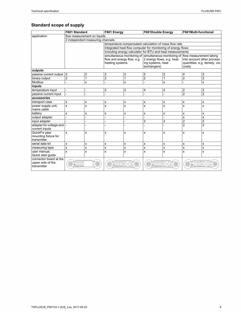
Standard scope of supply
F601 Standard F601 Energy F601Double Energy F601Multi-functionalapplication flow measurement on liquids
2 independent measuring channelstemperature-compensated calculation of mass flow rateintegrated heat flow computer for monitoring of energy flowsincluding energy calculator for BTU and heat measurementssimultaneous monitoring of flow and energy flow, e.g. heating systems
simultaneous monitoring of 2 energy flows, e.g. heat-ing systems, heat exchangers)
flow measurement taking into account other process quantities, e.g. density, vis-cosity
outputspassive current output 2 2 2 2 2 2 4 2binary output 2 1 2 1 2 1 2 2Modbus - x - x - x - xinputstemperature input - - 2 2 4 4 2 2passive current input - - - - - - 2 2accessoriestransport case x x x x x x x xpower supply unit, mains cable
x x x x x x x x
battery x x x x x x x xoutput adapter - - - - - - x xinput adapter - - - - 2 2 2 2adapter for voltage and current inputs
- - - - - - 2 2
QuickFix pipe mounting fixture for transmitter
x x x x x x x x
serial data kit x x x x x x x xmeasuring tape x x x x x x x xuser manual,Quick start guide
x x x x x x x x
connector board at the upper side of the transmitter
! $ ! "
& ' ( & '
! !
! $ ! "
& ' ( & '
) ( & '
* *
! !
! $ ! "
& ' ( & '
) ( & '
* *
! !
! $ ! "
& ' ( & '
) ( & '
* *
! !
+ + +
10 TSFLUXUS_F601V2-1-2US_Lus, 2017-05-23
FLUXUS® F601 Technical specification
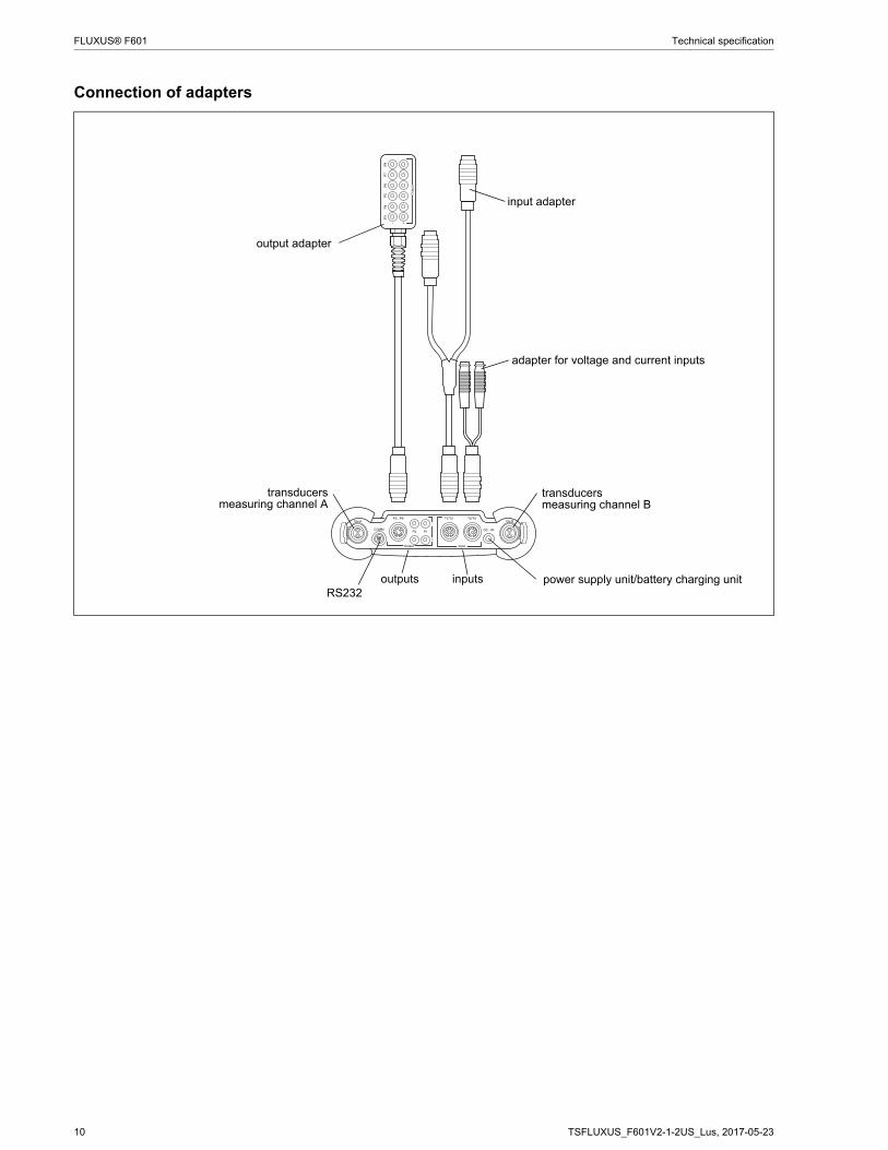
Connection of adapters
! $ ! "
& ' ( & '
) ( & '
* *
! !
+ + +
&'(&'
output adapter
input adapter
adapter for voltage and current inputs
transducersmeasuring channel A
RS232outputs inputs
transducersmeasuring channel B
power supply unit/battery charging unit
TSFLUXUS_F601V2-1-2US_Lus, 2017-05-23 11
Technical specification FLUXUS® F601
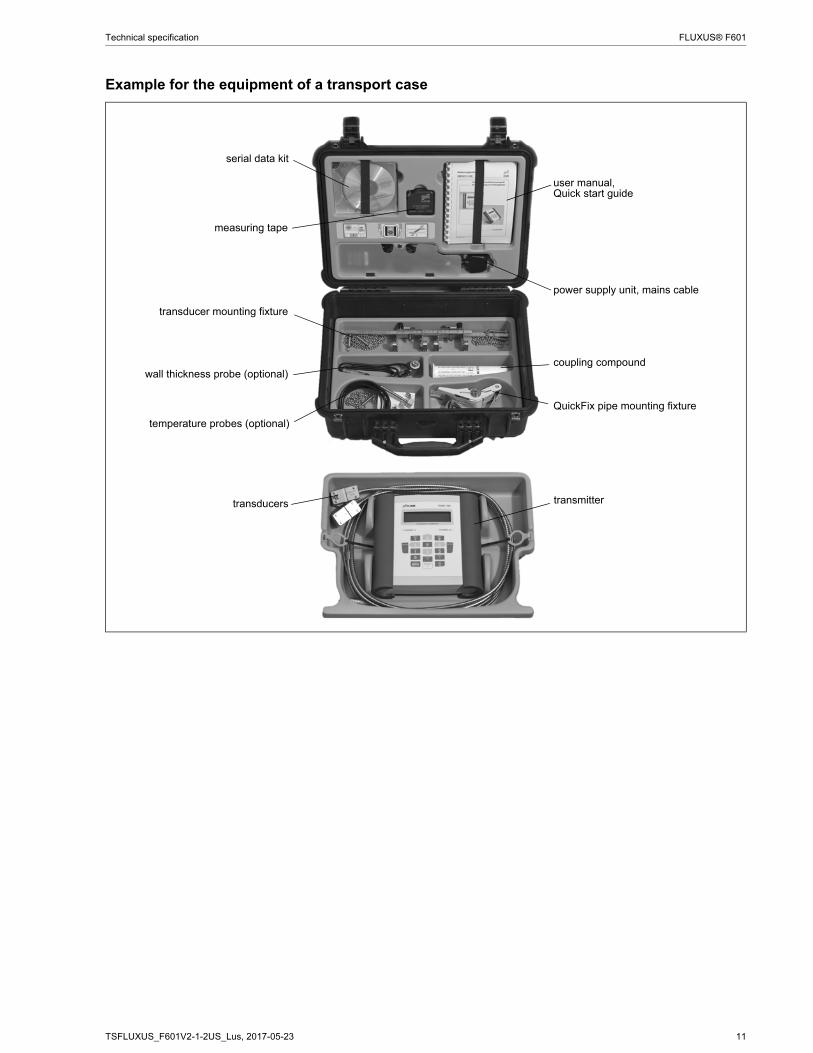
Example for the equipment of a transport case
serial data kit
power supply unit, mains cable
transducer mounting fixture
measuring tape
transmittertransducers
user manual,Quick start guide
coupling compoundwall thickness probe (optional)
QuickFix pipe mounting fixture
temperature probes (optional)

12 TSFLUXUS_F601V2-1-2US_Lus, 2017-05-23
FLUXUS® F601 Technical specification
Transducers
Transducer selection
transducer order code
FSG 15.7 19.7 157.5 255.9
FSK 3.9 7.9 78.7 255.9
FSM 2 3.9 39.4 133.9
FSP 0.98 2 15.7 23.6
FSQ 0.39 0.98 5.9 15.7
FSS 0.24 0.39 2.8
0.2 0.4 2 4 20 40 200inner pipe diameter [in]
transducer order code
FSG 0.43
FSK 0.2
FSM 0.08
FSP 0.04
FSQ 0.02
FSS 0.01
0.2 0.4 0.6 0.8 1 1.2pipe wall thickness [in]
recommended possible
TSFLUXUS_F601V2-1-2US_Lus, 2017-05-23 13
Technical specification FLUXUS® F601
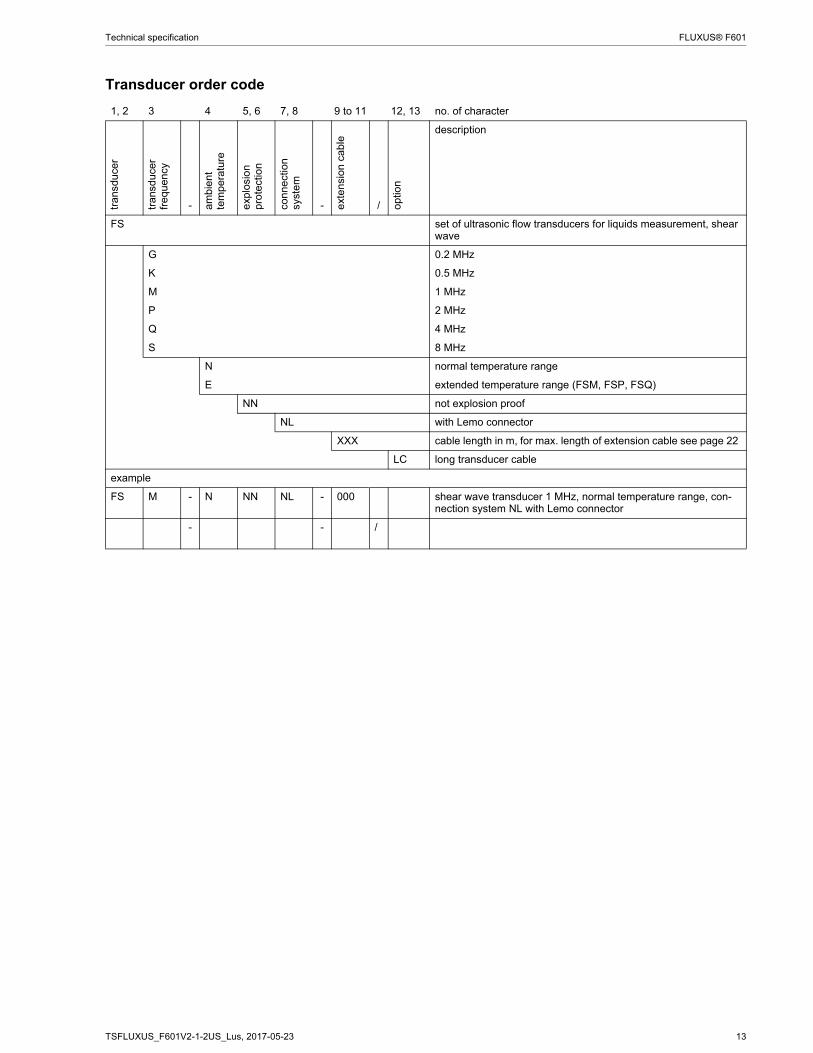
Transducer order code
1, 2 3 4 5, 6 7, 8 9 to 11 12, 13 no. of charactertr
ansd
ucer
tran
sduc
er
freq
uenc
y
- am
bien
t te
mpe
ratu
re
exp
losi
on
pro
tect
ion
conn
ect
ion
syst
em
- ext
ensi
on c
able
/ opt
ion
description
FS set of ultrasonic flow transducers for liquids measurement, shear wave
G 0.2 MHz
K 0.5 MHz
M 1 MHz
P 2 MHz
Q 4 MHz
S 8 MHz
N normal temperature range
E extended temperature range (FSM, FSP, FSQ)
NN not explosion proof
NL with Lemo connector
XXX cable length in m, for max. length of extension cable see page 22
LC long transducer cable
example
FS M - N NN NL - 000 shear wave transducer 1 MHz, normal temperature range, con-nection system NL with Lemo connector
- - /

14 TSFLUXUS_F601V2-1-2US_Lus, 2017-05-23
FLUXUS® F601 Technical specification
Technical data
Shear wave transducers
technical type CDG1NZ7 CLG1NZ7 CDK1NZ7 CLK1NZ7order code FSG-NNNNL FSG-NNNNL/LC FSK-NNNNL FSK-NNNNL/LCtransducer frequency MHz 0.2 0.2 0.5 0.5
inner pipe diameter dmin. extended in 15.7 15.7 3.9 3.9min. recommended in 19.7 19.7 7.9 7.9max. recommended in 157.5 157.5 78.7 78.7max. extended in 255.9 255.9 255.9 255.9pipe wall thicknessmin. in 0.43 0.43 0.2 0.2materialhousing PEEK with stainless steel
cap 304PEEK with stainless steel cap 304
PEEK with stainless steel cap 304
PEEK with stainless steel cap 304
contact surface PEEK PEEK PEEK PEEKdegree of protection NEMA 6 NEMA 6 NEMA 6 NEMA 6transducer cabletype 1699 1699 1699 1699length ft 16 29 16 29dimensionslength l in 5.1 5.1 4.98 4.98width b in 2.01 2.01 2.01 2.01height h in 2.64 2.64 2.66 2.66dimensional drawing
ambient temperaturemin. °F -40 -40 -40 -40max. °F +266 +266 +266 +266temperature compensation
x x x x
l
hb
l
hb
l
hb
l
hb
TSFLUXUS_F601V2-1-2US_Lus, 2017-05-23 15
Technical specification FLUXUS® F601
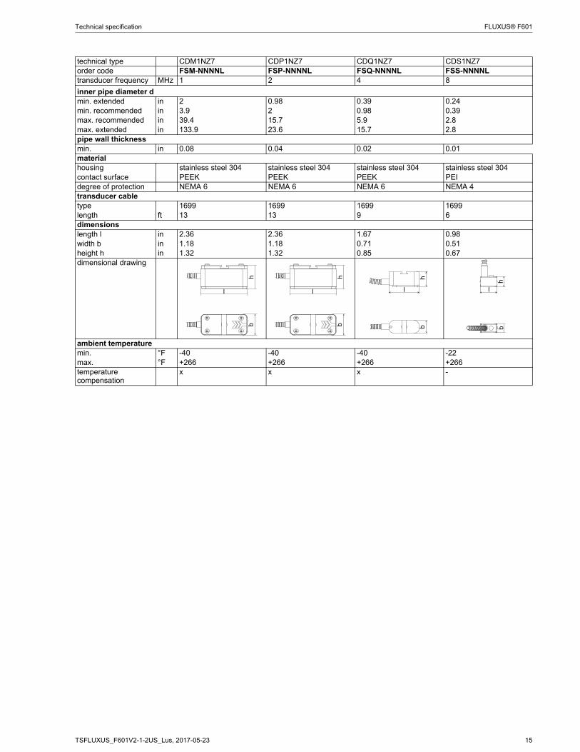
technical type CDM1NZ7 CDP1NZ7 CDQ1NZ7 CDS1NZ7order code FSM-NNNNL FSP-NNNNL FSQ-NNNNL FSS-NNNNLtransducer frequency MHz 1 2 4 8
inner pipe diameter dmin. extended in 2 0.98 0.39 0.24min. recommended in 3.9 2 0.98 0.39max. recommended in 39.4 15.7 5.9 2.8max. extended in 133.9 23.6 15.7 2.8pipe wall thicknessmin. in 0.08 0.04 0.02 0.01materialhousing stainless steel 304 stainless steel 304 stainless steel 304 stainless steel 304contact surface PEEK PEEK PEEK PEIdegree of protection NEMA 6 NEMA 6 NEMA 6 NEMA 4transducer cabletype 1699 1699 1699 1699length ft 13 13 9 6dimensionslength l in 2.36 2.36 1.67 0.98width b in 1.18 1.18 0.71 0.51height h in 1.32 1.32 0.85 0.67dimensional drawing
ambient temperaturemin. °F -40 -40 -40 -22max. °F +266 +266 +266 +266temperature compensation
x x x -
hb
l
hb
l
hb
l
hb
l
16 TSFLUXUS_F601V2-1-2US_Lus, 2017-05-23
FLUXUS® F601 Technical specification
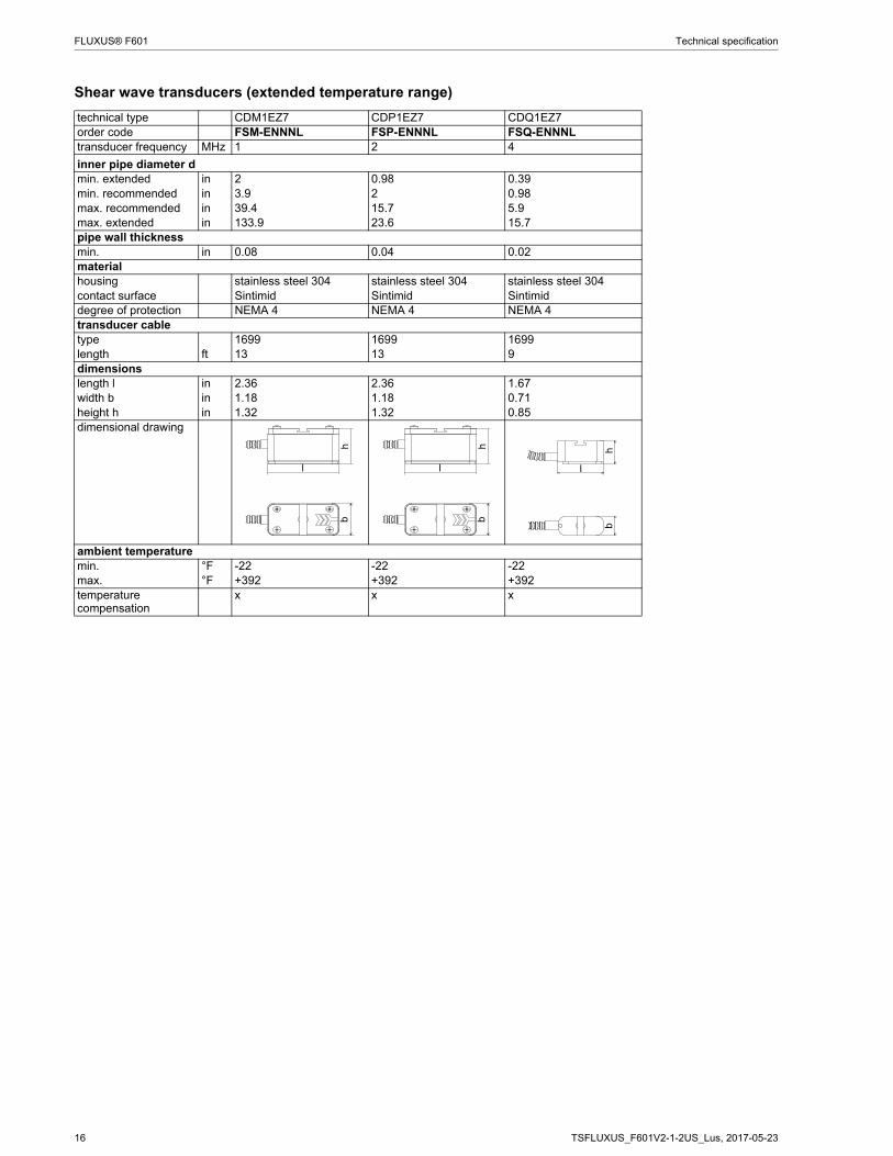
Shear wave transducers (extended temperature range)
technical type CDM1EZ7 CDP1EZ7 CDQ1EZ7order code FSM-ENNNL FSP-ENNNL FSQ-ENNNLtransducer frequency MHz 1 2 4
inner pipe diameter dmin. extended in 2 0.98 0.39min. recommended in 3.9 2 0.98max. recommended in 39.4 15.7 5.9max. extended in 133.9 23.6 15.7pipe wall thicknessmin. in 0.08 0.04 0.02materialhousing stainless steel 304 stainless steel 304 stainless steel 304contact surface Sintimid Sintimid Sintimiddegree of protection NEMA 4 NEMA 4 NEMA 4transducer cabletype 1699 1699 1699length ft 13 13 9dimensionslength l in 2.36 2.36 1.67width b in 1.18 1.18 0.71height h in 1.32 1.32 0.85dimensional drawing
ambient temperaturemin. °F -22 -22 -22max. °F +392 +392 +392temperature compensation
x x x
hb
lh
bl
hb
l

TSFLUXUS_F601V2-1-2US_Lus, 2017-05-23 17
Technical specification FLUXUS® F601
Transducer mounting fixture
Order code
1, 2 3 4 5 6 7 to 9 no. of character
tran
sduc
er
mo
untin
g fi
xtur
e
tran
sduc
er
- me
asur
emen
t a
rran
gem
ent
size
- fixat
ion
out
er p
ipe
dia
met
er
description
FS mounting frames
LM ladder chain mounting accessory
VP portable Variofix
TB tension belts
WL transducer box for WaveInjector
A all transducers
K transducers with transducer frequency G, K
M transducers with transducer frequency M, P
Q transducers with transducer frequency Q
S transducers with transducer frequency S
D reflect arrangement or diagonal arrangement/direct mode
R reflect arrangement
S small
M medium
C chains
N without fixation
L08 0.5 to 8 in
L22 0.5 to 22 in
010 0.39 to 3.9 in
025 0.39 to 9.8 in
055 0.39 to 21.7 in
150 2 to 59.1 in
210 2 to 82.7 in
example
VP A - D M - C 055 portable Variofix and chains
- -
18 TSFLUXUS_F601V2-1-2US_Lus, 2017-05-23
FLUXUS® F601 Technical specification
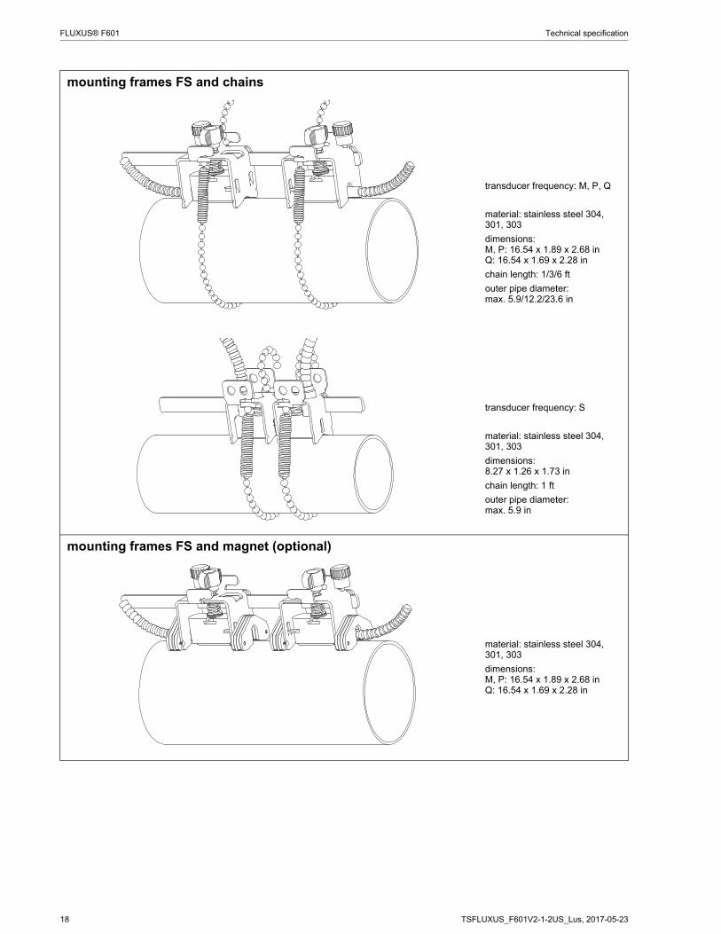
mounting frames FS and chains
transducer frequency: M, P, Q
material: stainless steel 304, 301, 303
dimensions:M, P: 16.54 x 1.89 x 2.68 inQ: 16.54 x 1.69 x 2.28 in
chain length: 1/3/6 ft
outer pipe diameter:max. 5.9/12.2/23.6 in
transducer frequency: S
material: stainless steel 304, 301, 303
dimensions:8.27 x 1.26 x 1.73 in
chain length: 1 ft
outer pipe diameter: max. 5.9 in
mounting frames FS and magnet (optional)
material: stainless steel 304, 301, 303
dimensions:M, P: 16.54 x 1.89 x 2.68 inQ: 16.54 x 1.69 x 2.28 in

TSFLUXUS_F601V2-1-2US_Lus, 2017-05-23 19
Technical specification FLUXUS® F601
ladder chain mounting accessory LM
transducer frequency: M, P, Q
chain length: 30/78 in
outer pipe diameter:max. 24 in
portable Variofix VP and chains
material: stainless steel 304, 301, 303
dimensions:16.3 x 3.7 x 2.99 in
chain length: 6 ft
portable Variofix VP and magnet (optional)
material: stainless steel 304, 301, 303
dimensions:16.3 x 3.7 x 1.57 in
(optional)

20 TSFLUXUS_F601V2-1-2US_Lus, 2017-05-23
FLUXUS® F601 Technical specification
tension belts TB
transducer frequency: G, K
material: steel, powder coated and textile tension belt
length: 16/22 ft
ambient temperature:max. 140 °F
outer pipe diameter:max. 59.1/82.7 in
transducer box WL for WaveInjector
see Technical specificationTSWaveInjectorVx-x
(optional)
transducer box and adapter

TSFLUXUS_F601V2-1-2US_Lus, 2017-05-23 21
Technical specification FLUXUS® F601
Coupling materials for transducers
Technical data
normal temperature range(4th character of transducer order code = N)
extended temperature range(4th character of transducer order code = E)
WaveInjector WI-400
< 212 °F < 338 °F < 302 °F < 392 °F < 536 °F 536 to 752 °Fcoupling compound type N
coupling compound type E
coupling compound type E
coupling compoundtype E or H
coupling pad type A and coupling pad type VT
coupling pad type B and coupling pad type VT
type ambient temperature material°F
coupling compound type N
-22 to +266 mineral grease paste
coupling compound type E
-22 to +392 silicone paste
coupling compound type H
-22 to +482 fluoropolymer paste
coupling pad type A max. 536 lead
coupling pad type B > 536 to 752 silver
coupling pad type VT 14 to +392 fluoroelastomer
coupling pad not to be used for transducer mounting fixture with magnets

22 TSFLUXUS_F601V2-1-2US_Lus, 2017-05-23
FLUXUS® F601 Technical specification
Connection systems
Transducer cable
Technical data
connection system NL
transducer frequency(3d character of transducer
order code)
F, G, H, K M, P Q S
NL
x y l1 x y l1 x y l1 x y lcable length ft 6 9 ≤ 82 6 6 ≤ 82 6 3 ≤ 82 3 3 ≤ 65
cable length (option LC) ft 6 22 ≤ 82 - - - - - - - - -1 > 82 to 328 ft on request
x, y = transducer cable lengthl = max. length of extension cable
transducer cable extension cabletype 1699 2551 1750standard length ft see table above 16
32max. length ft - see table above 32ambient temperature °F -67 to +392 -13 to +176 < 144cable jacketmaterial PTFE TPE-O PEouter diameter in 0.11 0.31 0.24thickness in 0.01 0.02color brown black blackshield x x xsheathmaterial stainless steel 304 - stainless steel 304outer diameter in 0.31 - 0.35remark optional
tran
smitt
er
l x y
-
TSFLUXUS_F601V2-1-2US_Lus, 2017-05-23 23
Technical specification FLUXUS® F601
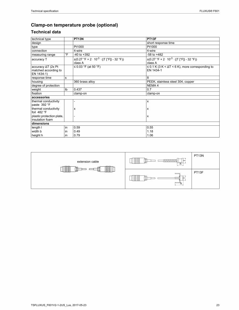
Clamp-on temperature probe (optional)
Technical data
technical type PT13N PT13Fdesign short response timetype Pt1000 Pt1000connection 4-wire 4-wiremeasuring range °F -40 to +392 -58 to +482
accuracy T ±(0.27 °F + 2 . 10-3 . (|T [°F]| - 32 °F))class A
±(0.27 °F + 2 . 10-3 . (|T [°F]| - 32 °F))class A
accuracy ∆T (2x Pt matched according to EN 1434-1)
≤ 0.03 °F (at 50 °F) ≤ 0.1 K (3 K < ∆T < 6 K), more corresponding to EN 1434-1
response time s 8housing 360 brass alloy PEEK, stainless steel 304, copperdegree of protection NEMA 4weight lb 0.437 0.7fixation clamp-on clamp-onaccessoriesthermal conductivity paste 392 °F
- x
thermal conductivity foil 482 °F
x x
plastic protection plate, insulation foam
- x
dimensionslength l in 0.59 0.55width b in 0.49 1.18height h in 0.79 1.06
PT13N
PT13F
extension cableh
lh
l

24 TSFLUXUS_F601V2-1-2US_Lus, 2017-05-23
FLUXUS® F601 Technical specification
Connection
Temperature probe
Connector
Cable
pin cable of temperature probe PT13F
cable of temperature probe PT13N
extension cable
1 white/blue white white2 red/blue red black3, 4, 5 not connected6 red red green7 white white red8 not connected
cable of temperature probe
cable of temperature probe
extension cable
temperature probe PT13F PT13Ntype 4 x 0.25 mm² black 4 x 24 AWG 4 x 18 AWGstandard length ft 9 20 -max. length ft - - 656cable jacket PTFE PTFE LS PVC
red red white whitered/blue red white/blue white
TSFLUXUS_F601V2-1-2US_Lus, 2017-05-23 25
Technical specification FLUXUS® F601
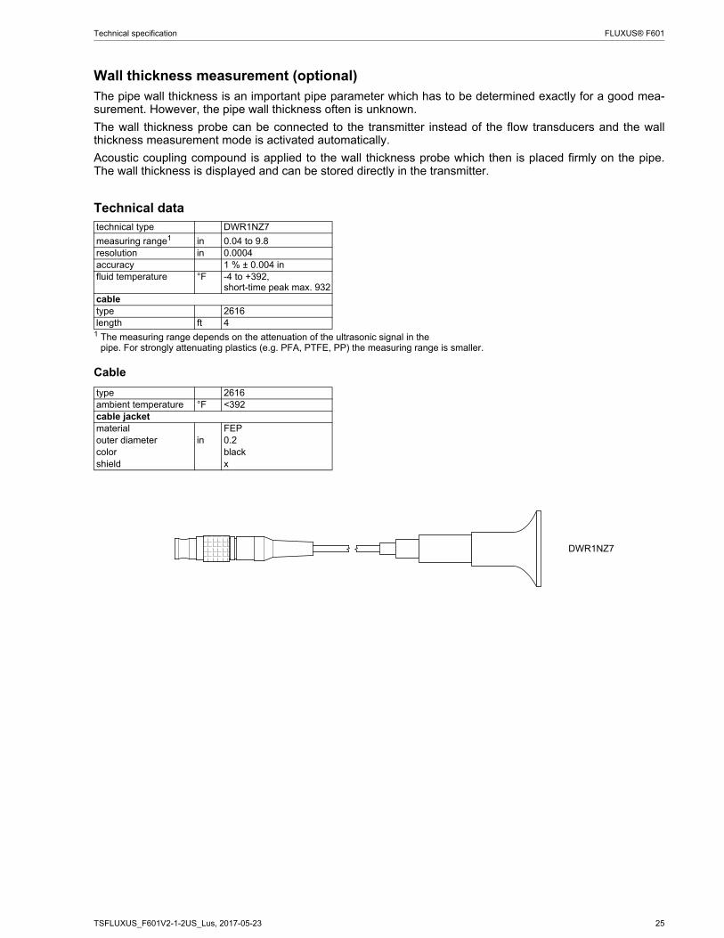
Wall thickness measurement (optional)The pipe wall thickness is an important pipe parameter which has to be determined exactly for a good mea-surement. However, the pipe wall thickness often is unknown.
The wall thickness probe can be connected to the transmitter instead of the flow transducers and the wallthickness measurement mode is activated automatically.
Acoustic coupling compound is applied to the wall thickness probe which then is placed firmly on the pipe.The wall thickness is displayed and can be stored directly in the transmitter.
Technical data
Cable
technical type DWR1NZ7
measuring range1 in 0.04 to 9.8resolution in 0.0004accuracy 1 % ± 0.004 influid temperature °F -4 to +392,
short-time peak max. 932сabletype 2616length ft 4
1 The measuring range depends on the attenuation of the ultrasonic signal in thepipe. For strongly attenuating plastics (e.g. PFA, PTFE, PP) the measuring range is smaller.
type 2616ambient temperature °F <392cable jacketmaterial FEPouter diameter in 0.2color blackshield x
DWR1NZ7

26 TSFLUXUS_F601V2-1-2US_Lus, 2017-05-23
FLUXUS® F601 Technical specification
FLEXIM AMERICAS Corporation
Edgewood, NY 11717
USA
Tel.: (631) 492-2300
Fax: (631) 492-2117
internet: www.flexim.com
e-mail: [email protected]
1-888-852-7473
Subject to change without notification. Errors excepted.
FLUXUS® is a registered trademark of FLEXIM GmbH.