potential use of ceramic coating as a thermal insulation ... · pdf filepotential use of...
TRANSCRIPT
NASA TECHNICAL
MEMORANDUM
CNLT»COco
NASA TM X-3352
POTENTIAL USE OF CERAMIC COATING
AS A THERMAL INSULATION
ON COOLED TURBINE HARDWARE
Curt H. Liebert and Francis S. Stepka
Lewis Research Center
Cleveland, Ohio 44^35*•??(} -1976
NATIONAL AERONAUTICS AND SPACE ADMINISTRATION • WASHINGTON, D. C. • FEBRUARY 1976
https://ntrs.nasa.gov/search.jsp?R=19760010053 2018-05-03T11:27:30+00:00Z

1. Report No.
NASA TM X-3352
2. Government Accession No. 3. Recipient's Catalog No.
4. Title and Subtitle
POTENTIAL USE OF CERAMIC COATING AS A THERMAL
INSULATION ON COOLED TURBINE HARDWARE
5. Report Date
February 19766. Performing Organization Code
7. Author(s)
Curt H. Liebert and Francis S. Stepka8. Performing Organization Report No.
E-8557
9. Performing Organization Name and Address
Lewis Research CenterNational Aeronautics and Space AdministrationCleveland, Ohio 44135
10. Work Unit No.
505-04
11. Contract or Grant No.
12. Sponsoring Agency Name and Address
National Aeronautics and Space AdministrationWashington, D.C. 20546
13. Type of Report and Period Covered
Technical Memorandum
14. Sponsoring Agency Code
15. Supplementary Notes
16. Abstract
An analysis was made to determine the potential benefits of using a ceramic thermal insulationcoating of calcia-stabilized zirconia on cooled engine parts. The analysis was applied to tur-bine vanes of a high-temperature and high-pressure core engine and a moderate-temperatureand low-pressure research engine. Measurements made during engine operation showed thatthe coating substantially reduced vane metal wall temperatures. Evaluations of the durabilityof the coating on turbine vanes and blades in a furnace and engine were encouraging.
17. Key Words (Suggested by Author(s) I
CeramicsInsulationStator blades
18. Distribution Statement
Unclassified - unlimitedSTAR Category 07 (rev.)
19. Security Classif. (of this report)
Unclassified20. Security Classif. (of this pagel
Unclassified21. No. of Pages
2322. Price'
$3.25
' Foi sale by the National Technical Information Service, Springfield. Virginia 22161

POTENTIAL USE OF CERAMIC COATING AS A THERMAL
INSULATION ON COOLED TURBINE HARDWARE
by Curt H. Liebert and Francis S. Stepka
Lewis Research Center
SUMMARY
An analysis was made to determine the potential benefits of using a ceramic thermalinsulation coating of calcia-stabilized zirconia on cooled engine parts. The analysis wasapplied to turbine vanes of a high-temperature and high-pressure advanced core engineand an existing moderate-temperature and low-pressure research engine. Measure-ments were also made of the insulating effect of the ceramic coating on a turbine vane inengine operation. And the durability of the coating on turbine vanes and .blades was eval-uated in a furnace and an engine.
The conditions assumed for the advanced core turbine analysis were an inlet gaspressure of 40 atmospheres, turbine-inlet gas temperatures of 1644 and 2200 K (2500°and 3500° F), and a cooling-air temperature of 811 K (1000° F). The conditions for theresearch engine turbine were an inlet gas pressure of 3 atmospheres, an inlet gas tem-perature of 1644 K (2500° F), and a cooling-air temperature of 319 K (114° F).
The results of the analysis illustrate that reductions in turbine-vane metal wall tem-perature of 390 K (700° F) are attainable at a coolant-to-gas flow ratio of 0. 10 for the ad-vanced core engine when the vanes are assumed to be coated with a 0. 051-centimeter(0. 020-in.) thickness of ceramic. Alternatively, large reductions in both coolant flowand metal temperature were also predicted. For example, core engine turbine vanescoated with 0. 051 centimeter (0. 020 in.) of ceramic could have both an eightfold reduc-tion in coolant flow and a 110 K (200° F) reduction in vane metal temperature comparedto an uncoated vane. Measurements made of the vane operating in the research engineshowed that a 0. 028-centimeter (0. Oil-in.) thickness of ceramic coating will reduce mid-span leading-edge metal temperature by 190 K (340° F) compared to the uncoated vane.Predictions of measured temperatures compared well with experiment.
Evaluations of the durability of the ceramic coating on turbine vanes and blades whentested in a furnace and during engine operation are encouraging. Further testing is re-quired at the high gas pressure and temperature conditions of advanced core engines.

INTRODUCTION
Past work with cooled rocket engines operating at high gas temperatures and heatfluxes, such as described in reference 1, shows that ceramic coatings are good heat in-sulators and can withstand large temperature differences through the coating thickness.Ceramic coatings have also been tried (ref. 2) as a means for reducing the metal tem-peratures of uncooled turbine blades in a turbojet engine during transient operation.These uses of heat barrier coatings, however, were for short time periods of a minuteor less. Furthermore, the engine tests reported in reference 2 were made at a rel-atively low turbine-inlet gas temperature and heat flux.
The operating conditions of current and future gas turbine engines - long-timesteady operation at high pressure, temperature and stress levels - impose more severestrains on the coating. Also, the coating has to withstand several thousand hours ofcyclic engine operation to gas temperatures as high as 2200 K (3500° F) without cracking,spalling, or eroding. In addition, to be useful, the airfoil coating should have a lowthermal conductivity and alow density and must not degrade turbine aerodynamic per-formance. The literature suggests that a stabilized zirconia coating may fulfill theserequirements. The results of tests presented in reference 3 show that a stabilized zir-conia coating has a very low thermal conductivity and density. In the tests described inreference 4, furnace heating elements of stabilized zirconia withstood 2000 hours and2000 cycles before failure. These elements were cycled between 2273 K (3631° F) and300 K (80 F). The hold time was 45 minutes at the higher temperature and 15 minutesat the lower temperature. Other tests described in reference 4 demonstrated that thezirconia withstood 1000 hours of steady-state operation at a temperature of 2373 K(3811° F). In reference 5, aerodynamic losses were significant when a rough zirconiacoating was applied. However, after the coating surface was smoothed, the aerodynamiclosses were reduced by a factor of 2 and were found to be caused primarily by the addi-tional thickness of the coating on the trailing edge. Based on these results, stabilizedzirconia appeared to be a reasonable candidate for insulating hot metal engine parts suchas combustor liners and turbine vanes, blades, and end-walls.
The study reported herein was conducted (1) to analyze the potential benefits of usinga calcia-stabilized zirconia ceramic as an insulating coating for reducing turbine-vaneairfoil metal temperatures and cooling flows and for increasing allowable turbine-inlettemperatures, (2) to evaluate the durability of the ceramic coating on turbine vanes andblades in furnace tests and engine operation, and (3) to measure the steady-state temper-ature reductions of a ceramic-coated vane metal wall in an engine and compare these re-sults with analysis.
To determine the heat transfer benefits to be achieved by using calcia-stabilized zir-conia as an insulator, a simple steady-state, one-dimensional heat transfer analysis wasmade on composite flat walls that consisted of a metal wall, a metallic bond coat, and

various thicknesses of zirconia coating. The analysis was made at gas and coolant con-ditions of both an advanced core engine turbine and a turbine in an existing research en-gine. The conditions assumed for the advanced core turbine were an inlet gas pressureof 40 atmospheres, turbine-inlet gas temperatures of 1644 and 2200 K (2500° and3500° F), and a cooling-air temperature of 811 K (1000° F). The conditions for the re-search engine turbine were an inlet gas pressure of 3 atmospheres, an inlet gas temper-ature of 1644 K (2500° F), and a cooling-air temperature of 319 K (114° F). Turbinecoolant-to-gas flow ratios were varied from 0.010 to 0.12. The zirconia coating thick-ness in the analysis ranged from zero to 0. 051 centimeter (0.020 in.).
Coating durability and insulating effect were experimentally evaluated in the turbineof a research engine at the gas conditions previously described and at coolant-to-gasflow ratios from about 0. 045 to 0.11. The adherence and durability of ceramic coatingswere also evaluated in an electric furnace at temperatures of 1088 to 1394 K (1500 to2050° F). The zirconia thickness on the vanes and blades was 0. 028 centimeter(0. Oil in.) in the engine tests and 0.005 centimeter (0. 002 in.) to 0.051 centimeter(0. 020 in.) in the furnace tests.
ANALYSIS
Method and Procedure
A simple one-dimensional steady-state heat balance through a composite wall,shown in the following sketch, was used to evaluate the potential benefits of using a cer-amic coating as a thermal barrier for turbine airfoils. Thermal radiation heat transferwas neglected in this analysis. Also, to simplify the analysis, the influence of the addedweight of the coating on the blade airfoil stress level was not considered.
If thermal conductivity is assumed to be a linear function of temperature, a heatbalance across the composite wall results in
q = V^S , W/m2 (1)
or
q=WTi ) te(r.) (TI -TsHr) ( T a - T s ) = f ? i v*-

The terms in equation (1) are defined in the appendix and are illustrated in the followingsketch:
CeramicBond- Metal wall
The parameters assumed to be known in this analysis were the coolant temperatureTC; the thicknesses of the various layers Lj, LJJ, and Ljjp and the heat transfer co-efficients on the gas and coolant sides h and h respectively. Appropriate values of& c
the heat transfer coefficients were obtained from the literature. The gas -side coeffi-cients were assumed to be constant for each engine condition of gas temperature andpressure selected, and. the coolant -side coefficients were assumed to be power functionsof the coolant flow. The thermal conductivities kj, kjj, and kjjj of each material layerwere obtained from the literature and correlated as linear functions of material temper-ature by using linear regression analysis. The conductivities were evaluated at layertemperatures that were the arithmetic averages of the temperatures at the respectiveboundaries (1, 2, 3, and 4) of each of the three layers (I, E, and El).
The bulk temperature of the total turbine -vane metal wall TJJ, . is a significantfactor affecting vane life and was the primary variable used in evaluating the benefits ofceramic coatings applied over vanes. The metal wall temperature at the leading -edgeregion TJJJ j was also used in comparing prediction with experimental data.
In predicting potential reductions in the metal waE temperatures TJJJ ^ or TJJJ ,with increases in ceramic coating thickness LT, we held T_. h_, T , and h constant
•*• & 5 C **for each of the two engines considered. These engines are discussed in the sectionEngine conditions. In predicting the potential of higher allowable gas temperature atgiven bulk metal wall temperatures T with increases in coating thickness, we held
h and T constant for each of the two engines considered. In predicting the potentialB *-
reductions in coolant-to-gas flow ratio at given bulk metal wall temperatures Tni b, weheld T , h and T constant for each of the two engines considered.
B B C
Conditions and Parameters
Engine conditions. - The gas and coolant conditions used were those of an advancedcore engine turbine and those of a turbine of an existing research engine. The advancedcore turbine had a high inlet gas pressure of 40 atmospheres, gas temperatures of either2200 or 1644 K (3500° or 2500° F), and a cooling-air temperature of 811 K (1000° F). Itwas chosen to evaluate the benefits of a ceramic thermal insulating coating on cooled tur-bines or parts that are subjected to conditions of high heat flux. The research enginehad a lower gas pressure level of 3 atmospheres, a gas temperature of 1644 K (2500° F),and a cooling-air temperature of 319 K (114° F). It was used to evaluate the benefits ofthe coating at lower heat flux conditions. The predicted reductions in metal wall temper-atures in the research engine were also compared with temperatures measured in the en-gine. A summary of these conditions and the equations for gas- and coolant-side heattransfer coefficients are given in table I. Cross sections of the turbine vanes of the ad-vanced core and research engines are shown in figures l(a) and (b), respectively.
Wall and coating parameters. - The thicknesses of the metal walls Lnl and thebond coating Ljj used in the analysis are given in table I. The thickness of the ceramiccoating Lj was varied from zero to 0.051 centimeter (0. 020 in.). The turbine-vanewall material was assumed to be MAR-M-509 (ref. 6) for the core engine and was MAR-M-302 (ref. 7) for the research engine. The bond coating material was nichrome(80Ni-20Cr), and the ceramic coating material was 5 weight percent of calcia-stabilizedzirconia.
Heat transfer coefficients. - Use was made of published and unpublished data to ob-tain the required heat transfer coefficients for each of the assumed engine conditions.
Core engine turbine: The gas-side heat transfer coefficient was an integrated aver-age of calculated local values determined at the hub, midspan, and tip locations aroundthe periphery of the vane. The effects of temperature on property values were neglected
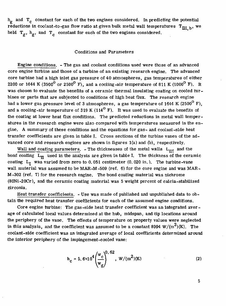
oin this analysis, and the coefficient was assumed to be a constant 8994 W/(m )(K). Thecoolant-side coefficient was an integrated average of local coefficients determined aroundthe interior periphery of the impingement-cooled vane:
r w \0 .62h =5.6X10⁴[-i] , W/(m2)(K) (2)

Research engine turbine: The heat transfer coefficients for the midspan leading -edge region and the average over the entire vane were obtained by using data from ref-erences 8 and 9 for gas-side conditions and from references 10 and 11 for coolant-sideconditions. The gas-side heat transfer coefficient at the leading edge of the vane was
jjh_ , = 1. 48 (Re)?' 5 (Pr).°- 4 _1, W/(m2)(K) (3)
g»ie l L D,le
owhich, for the conditions of the research engine, gives a value of 2326 W/(m )(K). Thecoolant-side heat transfer coefficient at the leading edge was
/w \°'49
hc,le=7-6xl° (— 1 , W/(m2)(K) (4)
n
The gas -side heat transfer coefficient for the entire vane was 1186 W/(m )(K), and thecorresponding coolant-side heat transfer coefficient was obtained from the relation
(5)
Thermal conductivity. - For the purposes of this analysis, thermal conductivities ofthe various layer materials were obtained from published experimental data as linearfunctions of average layer temperatures. The equations for the temperature variation ofthermal conductivity for the two metal wall materials considered (MAR-M-302 for theresearch engine and MAR -M -509 for the advanced core engine), the bond material (ni-chrome), and the ceramic coating material (calcia-stabilized zirconia) are presented intable n. The data for MAR-M-302 were obtained from reference 7, for MAR-M-509from reference 6, and for nichrome and the stabilized zirconia from reference 3.
APPARATUS AND PROCEDURE
The procedure used for depositing the ceramic coating onto the metal substrate wasto prepare the substrate surface, plasma spray on a bond coating, and then plasmaspray on the ceramic coating.
Various combinations of surface preparations, bond coatings, and ceramic coatingswere first evaluated for durability in furnace cyclic tests. One bond coating and one
ceramic coating thickness of each combination were applied to flat sheets of a nickel-base alloy material. Furnace cyclic testing was then performed on those coated vanesand blades that had the best coating combination, as determined from the flat sheet tests.A single surface preparation, one bond coat thickness, and three different ceramic coat-ing thicknesses were evaluated on these vanes and blades. The durability and the insu-lating capabilities of the coating were also evaluated on blades and vanes operating in aresearch turbojet engine. For these engine tests, one bond coat thickness and one ce-ramic coating thickness were used.
Coated Specimens
Flat sheets. - Twenty-seven coated flat specimens were prepared with combinationsof three different metal surface roughening preparations, three different bond coat mate-rials, and three different ceramic coating materials. The metal specimens were gritblasted (surface roughened) with either aluminum oxide or glass bead grit or were usedin the as-received condition. The bond coating materials investigated were nichrome(80Ni-20Cr), molybdenum, or nick el-aluminum (95. 5N1-4. 5A1). The ceramic coatingmaterials were 5 weight percent of calcia-stabilized zirconia, aluminum oxide, or haf-nium dioxide. The bond and ceramic coating thicknesses were maintained at 0. 0102centimeter (0.004 in.) and 0.0508 centimeter (0. 020 in.), respectively. The metalspecimens were fabricated from 0.198-centimeter (0.078-in.) thick Inconel alloy 718 HTsheet stock (ref. 6) to surface dimensions of 7. 6 centimeters by 15.2 centimeters (3 in.by 6 in.).
Vanes and blades. - All airfoil surfaces were grit blasted with aluminum oxide,after which a bond coating of nichrome was applied to a thickness of 0.0102 centimeter(0.004 in.). For the furnace tests, calcia-stabilized zirconia was applied at thicknessesof 0. 0051, 0. 0254, or 0.051 centimeter (0. 002, 0.010, and 0.020 in.). For the enginetests, the ceramic thickness was 0.028 centimeter (0.011 in.).
Coating Equipment and Procedure
Powders of bond and ceramic materials were applied separately with a plasmaflame spray gun (ref. 12). In the gun an electric arc is contained within a water-coolednozzle. Argon gas passes through the arc and is excited to temperatures of about17 000 K (30 000° F). The powders were mechanically fed into the nozzle and were al-most instantaneously melted at this temperature. The plasma of ionized gas containingthe melted powders impinged nearly perpendicularly upon the surfaces of the metal

specimens. During the plasma spray process, the metal substrate temperature did notexceed 420 K (300° F).
After the surfaces were cleaned or roughened, the bond coating and the ceramiccoating were applied within 15 minutes to minimize surface oxidation. Several otherfactors were controlled during the coating process. The inlet supply pressure to the
c e\
grit blasting equipment was maintained at about 7x10 N/m (100 psia), and the blastinggun was held nearly perpendicular to the surface. The plasma spray gun was also heldnearly perpendicular to the surface at distances of 15.2 and 10. 2 centimeters (6 and 4in.) for bond and ceramic applications, respectively.
Test Equipment
Furnace. - A commercial electric furnace was used to evaluate coating adherencein air. Coated specimens were placed in the furnace for 10 minutes and then withdrawnand air cooled to 300 K (80° F). The furnace temperature was 1367 K (2000° F) for testswith the sheet specimens and 1088 to 1394 K (1500° to 2050° F) for tests with the vanesand blades.
Engine. - An existing research turbojet engine modified to investigate air-cooledturbine vane and blade configurations was used to evaluate the durability and insulativeeffects of the coatings. Figures l(b) and (c) present cross sections of the vane and bladeused. Further details of the vane and blade are given in references 10 and 13, respec-tively. Instrumentation provided measurements of turbine-inlet gas temperature andpressure, cooling-air inlet temperature and flow rate, and test-vane metal walltemperature.
Two coated vanes and three uncoated vanes were used in the investigation. Thecoolant flow to each of these five vanes was measured in a bench test at room temper-ature over a range of inlet pressures. The flow rates between vanes were found to beuniform to within 2 percent.
One of the coated vanes and one of the uncoated vanes was instrumented with aChromel-Alumel thermocouple at the midspan of the leading edge. The thermocoupleswere imbedded in radial grooves in the wall to measure the average temperature of themetal with and without a ceramic insulating coating. The details of the thermocouple in-stallation are described in reference 14. The two coated vanes along with the three un-coated vanes were fitted into a segment of the vane ring where the coolant flow to thevane group could be independently controlled and measured.
Two coated blades were fitted into the turbine wheel for evaluation of coating dura-bility under rotating conditions. A thermocouple was installed in the metal wall of oneof the coated blades at the midspan leading-edge position.
Durability of the coating in the engine was evaluated as part of another research
8
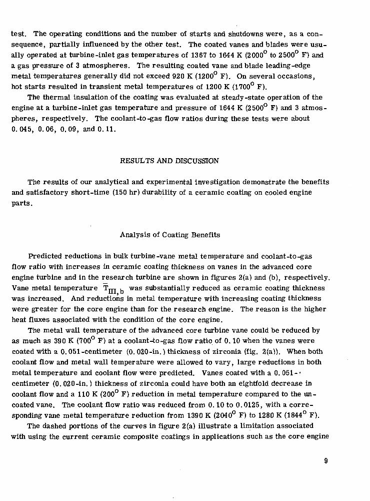
test. The operating conditions and the number of starts and shutdowns were, as a con-sequence, partially influenced by the other test. The coated vanes and blades were usu-ally operated at turbine-inlet gas temperatures of 1367 to 1644 K (2000° to 2500° F) anda gas pressure of 3 atmospheres. The resulting coated vane and blade leading-edgemetal temperatures generally did not exceed 920 K (1200° F). On several occasions,hot starts resulted in transient metal temperatures of 1200 K (1700° F).
The thermal insulation of the coating was evaluated at steady-state operation of theengine at a turbine-inlet gas temperature and pressure of 1644 K (2500° F) and 3 atmos-pheres, respectively. The coolant-to-gas flow ratios during these tests were about0.045, 0.06, 0.09, and 0.11.
RESULTS AND DISCUSSION
The results of our analytical and experimental investigation demonstrate the benefitsand satisfactory short-time (150 hr) durability of a ceramic coating on cooled engineparts.
Analysis of Coating Benefits
Predicted reductions in bulk turbine-vane metal temperature and coolant-to-gasflow ratio with increases in ceramic coating thickness on vanes in the advanced coreengine turbine and in the research turbine are shown in figures 2(a) and (b), respectively.Vane metal temperature Tni b was substantially reduced as ceramic coating thicknesswas increased. And reductions in metal temperature with increasing coating thicknesswere greater for the core engine than for the research engine. The reason is the higherheat fluxes associated with the condition of the core engine.
The metal wall temperature of the advanced core turbine vane could be reduced byas much as 390 K (700° F) at a coolant-to-gas flow ratio of 0.10 when the vanes werecoated with a 0.051-centimeter (0. 020-in.) thickness of zirconia (fig. 2(a)). When bothcoolant flow and metal wall temperature were allowed to vary, large reductions in bothmetal temperature and coolant flow were predicted. Vanes coated with a 0. 051 -•centimeter (0.020-in.) thickness of zirconia could have both an eightfold decrease incoolant flow and a 110 K (200° F) reduction in metal temperature compared to the un-coated vane. The coolant flow ratio was reduced from 0.10 to 0.0125, with a corre-sponding vane metal temperature reduction from 1390 K (2040° F) to 1280 K (1844° F).
The dashed portions of the curves in figure 2 (a) illustrate a limitation associatedwith using the current ceramic composite coatings in applications such as the core engine
9

with high gas temperature and pressure. The limitation is the ability of the ceramiccoating to adhere to the bond coating when the temperature at the interface between thesetwo layers exceeds 1367 K (2000° F). The basis for this ceramic/bond interface temper-ature limit, indicated by the tick marks in the figure, is discussed in the section CoatingDurability.
Thin layers of the ceramic coatings (<0.006 cm (0.002 in.)) at the highest coolant-to-gas flow ratio of 0.10 (fig. 2 (a)) were not sufficient to drop the temperature at theceramic/bond interface below the limiting temperature of 1367 K (2000° F). As the heatflux through the vane was reduced by lower coolant-to-gas flow ratios, thicker layers ofthe coating were required to give acceptable interface temperatures.
Reducing the heat flux also reduced the thermal gradients through the metal wall.Together with a constant limiting interface temperature, this resulted in slightly in-creased average vane wall metal temperatures (fig. 2(a)).
Although not shown in figure 2, calculations indicate large temperature dropsthrough the coating. The largest drop of 932 K (1678° F) occurred through a 0.051-centimeter (0.020-in.) thick ceramic coating on the turbine vane of the core engine at acoolant-to-gas flow ratio of 0.10. At these conditions, the coating outer temperaturewas 1980 K (3104° F) and the ceramic/bond interface temperature was 1048 K (1426° F).The temperature drop through the same coating thickness on the turbine vane of the re-search engine was calculated to be 351 K (632° F) at a coolant flow ratio of 0.06. Thecoating outer temperature for this condition was 1147 K (1604° F), and the ceramic/bondinterface temperature was 796 K (972° F). The resulting average ceramic coating tem-perature was considerably higher in the core engine (1514 K (2265° F)) than in the re-search engine (972 K (1290° F)). In general, the differences in gas temperature levelsand heat fluxes for the two engine conditions resulted in the temperature gradientsthrough the coating on the advanced core engine vanes being about 2. 7 times those of theresearch engine. The larger temperature gradient, coating exterior surface temper-ature, and ceramic/bond interface temperature would impose more severe strains on thecoating in the advanced core engine.
Figure 3 shows the calculated effect of coating thickness on allowable turbine-inletgas temperature for vanes operating at constant metal temperatures and coolant -to -gasflow ratios. Figure 3(a) shows the results for the gas pressure level of 40 atmospheresexpected'in an advanced core engine, and figure 3(b) the results for a gas pressure of3 atmospheres in the research engine. The base level of the turbine-inlet gas temper-ature for both engines was assumed to be 1644 K (2500° F) when there was no thermalbarrier on the vanes. It was at this base level that the metal temperatures of the un-coated vanes were determined for each coolant -to -gas flow ratio for each of the engines.The figure shows that, at the same vane metal temperature or coolant-to-gas flow ratio,the increase in allowable gas temperature was greater with increasing coating thickness
10

for the core engine than for the research engine. The higher heat flux through the tur-bine vanes of the core engine made the insulating properties of the coating more effectivethan it was in the lower-heat-flux research engine. For example, at a metal temper-ature of 1262 K (1812° F) a zirconia thickness of 0.0195 centimeter (0.0077 in.) per-mitted a potential increase of 556 K (1000 F) in the inlet gas temperature of the coreengine as compared to an allowable gas temperature increase of 85 K (153° F) for theresearch engine. Curves for coolant flow ratios of 0.03 and lower are not shown in fig-ure 3(a) because of unacceptably high ceramic/bond interface temperatures.
Coating Durability
The adherence of the coating composition was evaluated by cyclic testing of coatedflat sheet specimens and actual turbine-vane and blade hardware in an electric furnace:Testing at steady-state and cyclic conditions was also performed in the research turbo-jet engine.
Furnace tests. - The results of the tests on the 27 coated flat sheet specimens indi-cated that the best procedure and coating consisted of (1) abrasive blasting of the speci-mens with aluminum oxide grit, (2) plasma spraying of a bond coat of nichrome, and (3)plasma spraying of a coating of calcia-stabilized zirconia. The specimen with this coat-ing satisfactorily completed 10 cycles between room temperature and 1367 K (2000° F)before the tests were arbitrarily terminated so that tests on the durability of coatings onactual vanes and blades could be started. The sheet specimens with the other surfacepreparations and coating composites generally failed in two cycles.
The furnace cyclic test results on three different thicknesses of calcia-stabilizedzirconia on one vane and one blade showed that the coating will adhere well to a nichromebond coat without signs of deterioration for 40 cycles between 300 K (80° F) and 1367 K(2000° F). However, the zirconia ceramic separated from the bond coat after only 5cycles to temperatures of 1394 K (2050° F). The deterioration was especially apparenton the convex surfaces and leading edges of the blade and vane. These results indicatethat the ceramic/bond interface limiting temperature was about 1367 K (2000° F).
Engine tests. - The evaluation in engine operation of 0.028-centimeter (0.Oil-in.)thick calcia-stabilized zirconia on each of two vanes and blades, which was conducted aspart of other research, showed no evidence of coating deterioration after as many as 35start and stop cycles, four hot starts, and 150 hours at gas temperatures as high as1644 K (2500° F). The measured leading-edge vane and blade steady-state metal walltemperatures were as high as 920 K (1200° F), and the transient values were as high as1200 K (1700° F). Figure 4 shows one of the blades after completion of the tests. Nodeterioration is evident. Although these results are encouraging, more testing is re-quired. Based on the data given in the preceding section, the average coating temper-
11

ature and temperature drop through the coating are significantly greater for the core en-gine than for the research engine. As a consequence, the results of the tests reportedherein do not provide a basis on which to estimate the durability of the coating when it issubjected to the more severe conditions of the core engine. Testing is required at highergas pressures and temperatures.
Comparison of Measured and Predicted Coating Performance
Figure 5 compares calculated and measured wall metal temperatures at the midspanof the leading edge of an uncoated and a coated turbine vane operating in the research en-gine. The comparison is shown over a range of calculated coolant-to-gas flow ratiosfrom 0. 04 to 0.12 and includes measurements at ratios of about 0. 045, 0.06, 0.09, and0.11. The results show good agreement between prediction and measurement. The pre-dicted and measured reductions in leading-edge metal temperature for the coated vaneagreed within 25 K (45° F). The results show large reductions in leading-edge metaltemperature with the 0.028-centimeter (0. Oil-in.) thick coating. At the coolant-to-gasflow ratio of 0.06 the metal temperature was reduced by 190 K (340° F) - from 1055 K(1439° F) for the uncoated vane to 865 K (1097° F) for the coated vane.
CONCLUDING REMARKS
Thermal radiation heat flux was neglected to simplify the analysis. The effects arenegligible for the low pressure conditions of the research engine. However, as gaspressures and temperatures increase, the absorbed radiation heat flux increases, par-ticularly when the part directly views the combustion gases. The higher reflectance ofthe zirconia coating, 0. 8 compared to 0.2 for the bare metal, provides the additionalpotential benefit of reducing the radiative heat flux absorbed by hot parts. This benefitto the turbine vanes and blades was estimated to be small except at the leading edge ofthe first-stage vanes, which directly view the combustion flame. The higher reflectivityof the coating would be particularly beneficial for reducing the metal temperature of com-bustor liner walls. This benefit would be in addition to the insulating effect of the coat-ing. The ability of the coating to maintain a high reflectivity with prolonged engine oper-ation is not known and needs to be investigated.
It is important to emphasize that the benefits of a thermal barrier coating are di-rectly related to the level of heat flux through the uncoated hardware. As a consequence,hardware or portions of it that are poorly cooled will not show large benefits with a coat-ing. Trailing-edge regions of turbine vanes and blades of small engines, for example,
12

have a physical limitation on the use of effective cooling geometries and thus would notshow large benefits from a thermal barrier coating.
Application of thermal barrier coatings to existing hardware could limit the potentialbenefits for the reasons just mentioned and also could impose aerodynamic losses be-cause of increased trailing-edge thickness. Coating benefits can best be maximizedwhen the coating is integrated into an original design. The added weight of the coatingincreases the stress level in rotating parts, which may diminish some of the potentialbenefits of the coating.
Although the results obtained are encouraging, more testing is required at the highgas pressure and high temperature conditions of advanced core engines, where the coat-ing may be especially susceptible to particle erosion, corrosion, vaporization, thermalfatigue, and thermal shock.
SUMMARY OF RESULTS
The following are the results of calculations made to demonstrate the benefits ofzirconia ceramic coatings on turbine parts and of initial tests to evaluate the coatingdurability.
1. Reductions in vane metal temperature of as much as 390 K (700° F) at a constantcoolant-to-gas flow ratio of 0.10 were predicted for an advanced core turbine when thevanes were assumed to be coated with a 0.051-centimeter (0. 020-in.) thickness ofzirconia.
2. Alternatively, large reductions in both coolant flow and metal wall temperaturewere predicted for coated vanes operating in the advanced core turbine. Vanes coatedwith a 0.051-centimeter (0.020-in.) thickness of zirconia could have both an eightfolddecrease in coolant flow and a 110 K (200° F) reduction in metal temperature comparedto the uncoated vane.
3. The potential benefits from the ceramic coating were greater for a turbine of ahigh-gas-pressure core engine than for a low-gas-pressure research engine. At ametal temperature of 1262 K (1812° F), a zirconia thickness of 0.0195 centimeter(0.0077 in.) provided a potential increase in the allowable turbine-inlet gas temperatureof 556 K (1000° F) for the vanes of the core engine as compared to an increase of 85 K(153° F) for the research engine.
4. Zirconia coatings with thicknesses of 0. 0051 and 0.051 centimeter (0.002 and0. 020 in.) adhered well to vane and blade metal walls without signs of deteriorationwhen cycled 40 times by alternately heating in a furnace to 1367 K (2000° F) and aircooling to 300 K (80° F).
13

5. The zirconia coating on cooled turbine vanes and blades, which was tested as partof other research, withstood 35 start and stop cycles and 150 hours of testing in a re-search engine at gas temperatures as high as 1644 K (2500° F) without deteriorating.The coating consisted of a 0.028-centimeter (0.Oil-in.) thickness of calcia-stabilizedzirconia covering a 0.015-centimeter (0.006-in.) thickness of nichrome bond coat onMAR-M-302 metal walls.
6. The zirconia coating reduced the measured midspan leading-edge vane metal tem-perature in the research engine by 190 K (340° F) - from 1055 K (1439° F) for the un-coated vane to 865 K (1097 F) for the coated vane.
7. Predicted temperature reductions for turbine vane walls insulated with zirconiacoating compared well with experimental data taken in the research engine. The agree-ment was within 25 K (45° F).
Lewis Research Center,National Aeronautics and Space Administration,
Cleveland, Ohio, Nov. 19, 1975,505-04.
14
APPENDIX - SYMBOLS
D diameter
h heat transfer coefficient
k thermal conductivity of gas
kj,kjj,kjjj thermal conductivity of ceramic coating, bond coating, and metal wall,respectively
LpLjy, LJJJ thicknesses of ceramic coating, bond coating, and metal wall, respectively
Pr Prandtl number
q heat flux
Re Reynolds number
T temperature
TpTjj, TJJJ average layer temperature of ceramic coating, bond coating, and metalwall, respectively
w mass flow rate
Subscripts:
b bulk, integrated average over entire vane
c coolant side
f film
g gas side
le leading edge
1 gas-zirconia interface
2 zirconia-nichrome interface .
3 nichrome - metal wall interface
4 metal wall - coolant interface
15

REFERENCES
1. Price, Harold G.; Schacht, Ralph L.; and Quentmeyer, Richard J.:Reliability and Effective Thermal Conductivity of Three Metallic-CeramicComposite Insulating Coatings on Cooled Hydrogen-Oxygen Rockets.NASATND-7392, 1973.
2. Schafer, Louis J., Jr.; Stepka, Francis S.; and Brown, W. Byron: Comparison ofTheoretically and Experimentally Determined Effects of Oxide Coatings Suppliedby Fuel Additives on Uncooled Turbine-Blade Temperature During TransientTurbojet-Engine Operation. NACA RM E53A19, 1953.
3. Wilkes, K. E.; and Lagedrost, J. F.: Thermophysical Properties of PlasmaSprayed Coatings. (Battelle Columbus Labs.; NAS3-13329), NASA CR-121144,1973.
4. Halback, C. R. ; Page, R. J.; and Arthur, P. D.: 2200° C Oxidizing AtmosphereFurnace for Space Manufacturing. AIAA Paper 74-154, Jan.-Feb. 1974.
5. Stabe, Roy G.; and Liebert, Curt H.: Aerodynamic Performance of a Ceramic-Coated Core Turbine Vane Tested with Cold Air in a Two-Dimensional Cascade.NASA TM X-3191, 1975.
6. MAR-M Alloy 509: Physical Properties. Martin Marietta, 1969.
7. High Temperature, High Strength Nickel Base Alloys. The International Nickel Co. ,Inc., 1964.
8. Gladden, Herbert J.; Gauntner, Daniel J. ; and Livingood, John N. B.: Analysisof Heat-Transfer Tests of an Impingement-Convection and Film-Cooled Vane ina Cascade. NASA TM X-2376, 1971.
9. Gladden, Herbert J.; and Yeh, Frederick C.: Comparison of Heat-Transfer TestData for a Chordwise-Finned, Impingement-Cooled Turbine Vane Tested in aFour-Vane Cascade and a Research Engine. NASA TM X-2595, 1972.
10. Yeh, Frederick C. ; Gladden, Herbert J.; and Gauntner, James W.:Comparison of Heat Transfer Characteristics of Three Cooling Configurations forAir-Cooled Turbine Vanes Tested in a Turbojet Engine. NASA TM X-2580, 1972.
11. Yeh, Frederick C. ; et al.: Comparison of Cooling Effectiveness of Turbine Vaneswith and without Film Cooling. NASA TM X-3022, 1974.
12. Metals Handbook. Volume 2 - Heat Treating, Cleaning, and Finishing. Eighth ed.,Am. Soc. for Metals, 1964.
16
13. Fallon, Gerald E. ; and Livingood, John N. B.: Comparison of Heat-TransferCharacteristics of Two Air-Cooled Turbine Blades in a Turbojet Engine.NASA TM X-2564, 1972.
14. Growl, Robert J.; and Gladden, Herbert J.: Methods and Procedures for Eval-uating, Forming, and Installing Small-Diameter Sheathed Thermocouple Wiresand Sheathed Thermocouples. NASA TM X-2377, 1971.
17

TABLE I. - ANALYTICAL CONDITIONS
Parameter Turbine vane type
Advanced core engine Research engine
Turbine-inlet gastemperature, K
Turbine-inlet gaspressure, atm
Gas-side heat transfercoefficient, W/(m2)(K):
Leading edgeBulk
Coolant-side heat transfercoefficient, W/(m2)(K):
Leading edgeBulk
Coolant temperature, KMetal wall thickness, cmBond coating thickness, cmCeramic coating thickness, cm
1644 and 2200
40
1644
899423261186
5.6xl04(w /wj°'62
*• 5811
0.1270.0102
0 -0.051
7.6xl03(w /w )°'49
3190.102
0.01520 -0.051
TABLE E. - THERMAL CONDUCTIVITY OF CERAMIC, BOND,
AND METAL WALL MATERIALS
Material
MAR-M-302
MAR -M -509
NichromeC alcia-stabilized
zirconia
Use
Metal wall(research engine)
Metal wall (advan-ced core engine)
BondCeramic
Conductivity,W/(m)(K)
4.9X10"3 Tni+ 18.0
3.0X10"2 Tm+ 3.7
8. 3x10 "3 Tn + 6.74.1X10"4 fj + 0.46
Temperaturerange,
K
300 - 1260
590 - 1370
400 - 1400400 - 2400
Reference
7
6
33
18

Coating Metal wall
(a) Turbine vane of advanced core engine: impingement-cooled leading edge; impingement-cooled pressureand suction surfaces; convection-cooled trailing edge.
-Thermocouple
CD-11325-33
(b) Turbine vane of research engine: impingement-cooled and chordwise-finned leading edge-, impingement-cooled pressure and suction surfaces; convection-and film-cooled trailing edge. (From ref. 10.)
Metal wall
(c) Turbine blade of research engine: simple cast blade; all convection cooled. (From ref. 13.)
Figure 1. - Midspan cross sections of zirconia-coated vanes and blades used in the study.
19

2000
1600
« 1200
1500
1300
1100
Dashed lines represent regions whereceramic/bond interface temperatureT? is too high for good coatingadherence <T2 > 1367 K (2000° f))?
I 2000
1600
1200
800
5 900
g. 1500|— E&
]sf 1300
- I«ZJQQ
1100
900
Coolant-to-gasflow ratio,
(a) Advanced core turbine: inlet gas temperature, 2200 K (3500° F);gas pressure, 40atm; coolant temperature, 811 K (1000° F).
700.01 .02 .03 .04 .05
Zirconia coating thickness, Lj, cm.06
0 .005 .010 .015Zirconia coating thickness, Lj, in.
.020
(b) Research engine turbine: inlet gas temperature, 1644 K (2500° F);gas pressure, 3atm; coolant temperature, 319 K (114° F).
Figure 2. - Reductions in metal temperatures and coolant flows for vanes coatedwith various thicknesses of zirconia.
20

3400i—
3000 —
26001—
2200
2000
1800
1AIY1
/// / Coolant-to-gas/// / flow ratio,
ft'/ w ;w
" /7
ft 0. 10
F .06f .04
1 1 1 1
Bulk wall metaltemperature,
TTTT
K (°F)
1159 (1626)1183 (1669)1215 (1727)1262 (1812)
1 1
(a) Advanced core engine: inlet gas pressure, 40atm;coolant temperature, 811 K (1000° F).
I
sI
I€
3300r—
2900
25001—
a.
B 2200
2000
1800
1600
Coolant-to-gas Bulk wall metalflow ratio, temperature,
T
K (°F)
wc/wg
— 0.06
.04
.02
.01
944 (1239)1035(1403)1187 (1677)1318 (1912)
.01 .02 .03 .04 .05Zirconia coating thickness, Lj, cm
I I I I
.06
.005 .010 .015 .020Zirconia coating thickness, Lj, in.
(b) Research engine turbine: inlet gas pressure,3atm; coolant temperature, 319 K (114° F).
Figure 3. - Increases in allowable turbine-inlet gas temperature forvanes coated with various thicknesses of zirconia. Base turbine-inlet temperature for uncoated vanes, 1644 K (2500° F).
21

Rust deposited duringoperation -^
\\\
\
r Leading edge
: 'A'-'• (jjCarbon deposited during
I shutdown.Leading edge -»
st deposited duringoperation
C-74-683 BL _
(a) Suction surface. (b) Pressure surface.
Figure 4. - Ceramic-coated blade after testing in research engine.
C-74-682
1600,—™OJ OJ
1200
r I * 120001 Q, »—r
800
^ 5 loooSll-
•2 800
On
Uncoated vaneCoated vane
Prediction Zirconia coatingthickness,
Li-cm (in.)
a 028 Itt Oil)
600.04 .06 .08 .10 .12
Coolant-to-gas flow ratio, wc /w_
Figure 5. - Comparison of calculated and measured midspanleading-edge wall metal temperatures of uncoated andzirconia-coated turbine vanes operating in a researchengine. Inlet gas temperature, 1644 K (2500° F); inlet gaspressure, 3atm ; coolant temperature, 319 K (114° F).
22 NASA-Langley, 1976 E-8557

NATIONAL AERONAUTICS AND SPACE ADMINISTRATION
WASHINGTON. D.C. 2OS46
OFFICIAL BUSINESS
PENALTY FOR PRIVATE USE S3OO SPECIAL FOURTH-CLASS RATEBOOK
POSTAGE AND FEES PAIDNATIONAL AERONAUTICS AND
SPACE ADMINISTRATION451
POSTMASTER : If Undeliverable (Section 158Postal Mnnii.il) Do Not Return
"The aeronautical and space activities of the United States shall beconducted so as to contribute . . . to the expansion of human knowl-edge of phenomena in the atmosphere and space. The Administrationshall provide for the widest practicable and appropriate disseminationof information concerning its activities and the results thereof."
—NATIONAL AERONAUTICS AND SPACE ACT OF 1958
NASA SCIENTIFIC AND TECHNICAL PUBLICATIONSTECHNICAL REPORTS: Scientific andtechnical information considered important,complete, and a lasting contribution to existingknowledge.
TECHNICAL NOTES: Information less broadin scope but nevertheless of importance as acontribution to existing knowledge.
TECHNICAL MEMORANDUMS:Information receiving limited distributionbecause of preliminary data, security classifica-tion, or other reasons. Also includes conferenceproceedings with either limited or unlimiteddistribution.
CONTRACTOR REPORTS: Scientific andtechnical information generated under a NASAcontract or grant and considered an important'contribution to existing knowledge.
TECHNICAL TRANSLATIONS: Informationpublished in a foreign language consideredto merit NASA distribution in English.
SPECIAL PUBLICATIONS: Informationderived from or of value to NASA activities.Publications include final reports of majorprojects, monographs, data compilations,handbooks, sourcebooks, and specialbibliographies.
TECHNOLOGY UTILIZATIONPUBLICATIONS: Information on technologyused by NASA that may be of particularinterest in commercial and other non-aerospaceapplications. Publications include Tech Briefs,Technology Utilization Reports andTechnology Surveys.
Details on the availability of these publications may be obtained from:
SCIENTIFIC AND TECHNICAL INFORMATION OFFICE
N A T I O N A L A E R O N A U T I C S A N D S P A C E A D M I N I S T R A T I O NWashington, D.C. 20546