reflective coating on fibrous insulation for reduced · pdf filereflective coating on fibrous...
TRANSCRIPT

NASA Contractor Report 201733
Reflective Coating on Fibrous Insulationfor Reduced Heat Transfer
Derek D. Hass, B. Durga Prasad, David E. Glass, and Karl E. Wiedemann
Analytical Services & Materials, Inc., Hampton, Virginia
Contract NAS 1-19708
August 1997
National Aeronautics and
Space Administration
Langley Research Center
Hampton, Virginia 23681-0001
https://ntrs.nasa.gov/search.jsp?R=19970031799 2018-05-03T11:42:07+00:00Z

l,
The use of trademarks or names of manufacturers in this report is foraccurate reporting and does not constitute an official endorsement, eitherexpressed or implied, of such products or manufacturers by the NationalAeronautics and Space Administration.

Reflective Coating on Fibrous Insulation forReduced Heat Transfer
Derek D. Hass, B. Durga Prasad, David E. Glass, and Karl E. Wiedemann
Analytical Services and Materials, Inc.107 Research Drive
Hampton, VA 23666
Abstract
Radiative heat transfer through fibrous insulation used in thermal protectionsystems (TPS) is significant at high temperatures (1200°C). Decreasing the radiative heattransfer through the fibrous insulation can thus have a major impact on the insulatingability of the TPS. Reflective coatings applied directly to the individual fibers in fibrousinsulation should decrease the radiative heat transfer leading to an insulation withdecreased effective thermal conductivity. Coatings with high infrared reflectance havebeen developed using sol-gel techniques. Using this technique, uniform coatings can beapplied to fibrous insulation without an appreciable increase in insulation weight ordensity. Scanning electron microscopy, Fourier Transform infrared spectroscopy, andellipsometry have been performed to evaluate coating performance.
b
d
Ir
IsLN
n
nH
nn
1
n
Q_
r
z
P't
Nomenclature
back scattered fractionfilm thickness
reference reflected intensity
reference reflected intensitymedium thickness
number density of fibersindex of refraction
high refractive indexlow refractive index
film refractive index
substrate refractive index
extinction efficiency
scattering efficiency
fiber radius
number of coating layers
wavelengthreflectancetransmittance

Introduction
The reusable launch vehicle (RLV) currently under development for advancedspace applications will require thermal protection performance exceeding that required onpast vehicles. One option being considered for this application is a metallic thermal
protection systems (TPS), as shown in Figure 1, where fibrous insulation is placedbetween an Inconel 617 honeycomb external panel and a titanium honeycomb internalpanel. The fibrous insulation provides an extremely lightweight insulator between thehoneycomb sandwich panels. Saffil ® insulation (- 96% A1203, - 4% SiO2, with a meanfiber diameter of 3 lxm) is an attractive insulation for this system since it provides anexcellent combination of low weight, negligible weight loss below 1700°C, and lowthermal conductivity. Despite Saffirs ® already excellent properties, further advancement
may still be necessary to meet future design requirements. Therefore, any techniquewhich can further enhance the low thermal conductivity of Saffil ® without drasticallyincreasing its weight will advance current technology.
External honeycombsandwich
Fibrous insulationInternal honeycomb
sandwich panel
Figure 1: Schematic diagram of metallic thermal protection system with fibrousinsulation between honeycomb panels.
The heat transfer through fibrous insulation is composed of conduction, convection,and radiation contributions. The importance of the radiation component increases withtemperature, and is important even at the relatively low temperatures experienced inhome attic insulations [1]. Thermal radiation accounts for 40-50% of the total heat
transfer in light weight fibrous insulation at moderate temperatures [2]. Figure 2 showsthe approximate percentage of each mode of heat transfer in fibrous insulation at oneatmosphere. In reentry conditions (i.e. high temperature (1200°C) and vacuum pressures)the radiative contribution dominates [10-11] the heat transfer.
The interaction of thermal radiation with individual fibers in fibrous insulation has
been studied by several authors. Mathes, et al. [3], determined the extinction coefficient
of fibrous insulation using Mie-scattering theory with an emphasis on radiation oblique tothe fibers. Lee [4] analyzed the scattering regimes of parallel fibers accounting for
2

dependentscattering.His results indicate that the scattering is strongly dependent on thecomplex index of refraction. Cunnington, et al. [5], experimentally studied the scatteringof radiation by coated fibers. The fibers were 7.9 l.tm mean diameter silica fibers with a0.25 ktm coating. The experimental results compared well with theoretical predictions.
In addition to studies on the fundamentals of radiation heat transfer in fibrous
insulation, several studies have been performed on methods to reduce the heat transfer
through fibrous insulation. Verschoor, et al. [6], experimentally measured the effectivethermal conductivity of glass fibrous insulation ranging in density from 0.5 to 8.4 lb/ft 3.
They determined that at low pressures, the heat transfer by radiation is very small for the4.6 lb/ft 3 insulation, but becomes appreciable as the density is reduced to 0.5 lb/ft 3. Solidconduction due to fiber contact was found to contribute very little to the heat transfer in
the fibrous insulation studied. They suggest that the thermal conductivity can be reducedby using fibers with small diameters and high density insulation, i.e., 0.01 pm diameterfibers in a 10 lb/ft 3 insulation. Thermal conductivity can also be reduced by sealing a
low conductivity gas within the insulation, evacuating the insulation, or filling the poreswith powders of very fine particle size. Earlier studies [7] indicate that it is possible toreduce radiative heat transfer in silica insulation by applying dielectric coatings to thefibers.
100
80
60
% of heattransfer mode
40
20
Gas conduction
N_ Solid conduction
0 I I I /"1 I I I
300 400 500 600 700 800 900 1000
Mean temperature, °C
Figure 2: Contribution of each mode of heat transfer in fibrous insulation at one
atmosphere.
Most glasses undergo a sharp transition from almost total transparency to totalopacity in the 5 to 10 ktm infrared region depending upon the chemical composition andthickness [6]. Fibers can be opacified by variations in the chemical composition that willshift the transition to a lower wavelength. Fibrous insulation has also been opacified bythe dispersion of reflective metallic particles or flakes throughout the insulation [8]. Thisdispersion of particles substantially increased the radiation attenuating efficiency of thefibrous insulation with very little increase in the insulation bulk density.
3

The thermal conductivity of fibrous insulation is dependent on temperature, airpressure, density, fiber diameter, and the optical properties of the individual fibers. Thetemperature, pressure, and density are all fixed by either environmental conditions ordesign requirements and the fiber diameter is already optimized for low thermalconductivity. As a result, altering the optical properties of the fibers presents the bestopportunity for improving the thermal conductivity of the insulation. The opticalproperties of individual Saffil ® fibers can be altered by coating the fibers with layers of ahigh index of refraction material [9]. Such a coating should result in an improvement inthe reflectivity of the fibers and thus a decrease in the effective thermal conductivity.The radiative contribution is strongly dependent on the optical properties of the insulationfibers [12-13]. Therefore an increase in the index of refraction of the fibers should effect
the thermal conductivity of the fibrous insulation.
The objective of this work was to reduce the radiative heat flux through ceramicfibrous insulation by enhancing its reflectivity. Increased reflectance can beaccomplished through the development and application of reflective coatings. Severalcoating approaches were considered including: high index of refraction ceramic coatings,multilayer quarterwave stacks, and coatings of nanocomposite materials. Coatings wereapplied using a sol-gel technique which permitted a uniform coating to be appliedwithout unwanted increases in insulation weight and density.
Theoretical Approach
The idea of coating fibers with a reflective layer has been proposed as a means toreduce heat transfer through the insulation. Internal reflections promote the distributionof radiative energy within the medium, making the transient temperature distributionsmore uniform.
r I r2(1-r12)e i_•
I I I I/
/
' 'n 1 _ _ r2_/l_'r_= '_,/ _ ,
BnnuuFigure 3: Reflections from a nonabsorbing, homogeneous thin film at normal
incidence.
The refractive index has two effects on the temperature distributions within a
medium [15]. One is that internal reflections (resulting from a high refractive index) helpdistribute energy within the medium, resulting in a more uniform transient temperaturedistribution. However, reflections from the boundaries tend to contain radiation within
the medium for larger refractive indices. For optically thin layers, where the mediuminteraction with the thermal radiation is negligible and the temperature distribution isrelatively uniform, the effect of the reflective boundaries dominates over the refractive
4

indexeffects,andincreasingtherefractive index will tend to keepthe energywithin themedium. For anoptically thick medium,wherethemediuminteractionwith the thermalradiation is significant, the effect of the refractive index is more important than thereflective boundaries, and increasing the refractive index helps maintain uniformtemperaturesthroughoutthemedium• Specifically,for anoptical thicknesslessthan 10,internal reflections provided by a refractive index of 2 have a substantial effect inequalizingthe temperaturedistributions[14]. For the casesstudiedin reference14withconvective heating, the more uniform temperaturedistribution resulted in a lowermaximumtemperature.
Whena thin film, or coating,is appliedto a material, its optical propertiescanbealtered[16]. For thecaseof a nonabsorbing,homogeneousfilms, asshownin Figure 3,thesepropertieswill dependon film thickness,d, radiationwavelength,_,,andthe indexof refractionof the film, n, andsubstrate,n. From Figure4 it canbeseenthat if a thinfilm is appliedto asubstratewith n > n, th_nan increasein reflectancewill occur. This• . . 1 . nincrease wall reach a maximum at a film thickness of _,/4nd. The reflectance has a
oscillatory nature due to interference effects as a maximum occurs at _,14, 3_/4, 5274 etc.This result has two important effects. One is that the same coating can be both reflectiveand nonreflective depending on its thickness. The second is that coating reflectance is
dependent on the wavelength of the media to be reflected. This means that a coating thatis reflective in the visible spectrum may not be reflective to infrared radiation.
100
90
80
70(1)¢..)c 60
0• 50
o'- 40
30
20
10
r1= -r 2 =
32
28
24
20
16
12
8
4
(1)0t-
O(D
n-
o _4 _2 3_2
nld
Figure 4: Reflectance as a function of nld for films of various refractive index valueson a glass substrate.
To substantially increase the reflectivity of the individual fibers in insulationsystems, coatings must be developed which have a high index of refraction, n. Ceramicmaterials, specifically oxides, however, offer the ability to modestly increase the effective

n value for the insulation fibers. Using sol-gel techniques,oxides can be applied tofibrous insulationto producereflective coatings(if n0oa,,_> 1.7). These oxide coatingscan also be applied in multilayer quarterwave stacks or used as a matrix material for
nanocomposite materials to yield coating systems with improved reflectance over singleoxide films. Several approaches have been explored with the details described below.
High Index of Refraction Coating
The simplest approach for a reflective coating is a material with an index ofrefraction higher than the base fibers. This will result in an increase in reflectance which
is dependent on the index of refraction of the coating, the thickness of the coating, andthe wavelength of the media to be reflected. As shown above in Figure 3, the reflectanceincrease is dependent on the coating thickness. Therefore, it is important to obtain athickness approaching nd = _,/4 to obtain maximum reflectance. In addition, it can be
seen that as the wavelength of the media to be reflected increases, so does the coatingthickness required to obtain the maximum reflectance. At the expected temperatures ofthe insulation in the thermal protection systems, near infrared reflectance is required (1-5_tm). The required wavelength creates a potential problem in that the coating thicknessesrequired to substantially increase the reflectance may lead to an unacceptable increase inweight. As a result, coating approaches which can produce a higher reflectance at lowerthickness values may be needed.
Multilayer Quarterwave Stack
Since the high reflectance of a single film is due to the constructive interference of
the thermal radiation reflected at both surfaces, the reflectance can be enhanced by phaseagreement of the reflected radiation from multiple coating layers. This requires a stack ofalternating high (H) and low (L) refractive index layers. Next to the substrate is the usualhigh index layer so that the stacking order is HLHLHLHL... For z layers, it has beencalculated that the maximum reflectance is given by [17]
[";;' z-, ]2+ nzL-'n2(1)
where nil, nL, and n 2 are the high, low, and substrate indices, respectively.
Improved reflectance over a single high index of refraction layer can be achievedusing multilayer quarterwave stacks. The effect increases as the difference between the
index of refraction increases with the effective index of refraction expressed as;
neef = (nil z+I / nLZ-1)I/2
where n H is the index of refraction for the high index layer and n L is the index ofrefraction for the low index layer. The average index of refraction values for some of the
high-temperature ceramic oxides are presented in Table 1 [18]. On comparison, bothTiO 2 and ZrO 2 oxides meet the requirement of high-temperature stability and high indexof refraction. On the other hand, SiO 2 has a low index of refraction. Therefore, TiO 2 (H)- SiO 2 (L) and ZrO 2 (H) - SiO 2 (L) combinations were chosen to examine reflective
characteristics. When considering metal oxides, titania (n=2.61) and silica (n=1.54) offerthe largest difference in index of refraction. For a three layer quarterwave stackconsisting of TiO 2 and SiO 2 the effective index of refraction is given as:
6

nef f = ( 2.614 / 1.542) 1/2 = 4.42
This approach has interest due to the high theoretical reflectance possible.However, there are several disadvantages. The greatest, for the case of Saffil ® insulationwhere the fiber diameters are relatively small, is that three quarterwave layers (the
minimum necessary) leads to a large increase in weight (especially for wavelengthsgreater than 2 I.tm) and these layers are also difficult to adequately apply to the fibers. Inaddition, obtaining a coating of a specified thickness is difficult to quantify so that qualitycontrol becomes an issue. As a result, this concept does not entirely meet the specified
criteria, and therefore a concept that will give improved reflectance without increasingthe coating thickness and complexity is still desired.
Table 1: Index of Refraction of Several Metal Oxides [18]
Ceramic Material Index of Refraction
TiO 2 2.61Ta20 s 2.50FezO 5 2.35ZrO 2 2.10A1203 1.70SiO 2 1.54
Nanocomposite Layers
The need for high reflectance with a simple, low weight coating may be satisfied bythe development of nanocomposite layers. These materials consist of nano-sized particlesin a ceramic matrix. This can lead to non-linear optical properties which may showdecreases in the transmissivity of the material [19-20]. The major advantage of such an
approach is the potential for a relatively high coating reflectance/thickness ratio. Afavorable ratio would allow for an adequate increase in fiber reflectance without an
unacceptable weight gain or the need to apply multiple layer coatings. In addition, if anacceptable increase in reflectance can be achieved at thicknesses less than L/4, then notonly is the weight increase limited, but non uniform thicknesses in the coating can betolerated to some degree. If a coating with a thickness of _,/4 is used, any variation inthickness will lead to a decrease in the total reflectivity due to the peak in reflectance at
_,/4. However, thinner coatings, away from the reflectance peak, would not be effectedby thickness variations since a thinner coating in one region would result in a thickercoating in another, and the average reflectivity would remain similar to a uniform layerthickness throughout. Due to the difficult nature of applying coatings to fibrousinsulation, precise control over coating thickness and uniformity is marginal at best. As aresult, a coating which is not critically dependent on thickness and uniformity offers a bigadvantage. A large variety of nanocomposite coatings are possible with limitations setmostly by finding suitable sol-gel chemistries to obtain the nanosized particles required.Systems that show promise include TiO2(Pt) and SiO2(Pd), with the TiOE(Pt) being themost easily applied to the insulation fibers at present.
Some possible drawbacks of this concept exist. One is the unknown thermalstability of these coatings. With the high service temperatures experienced, the
possibility of particle growth leading to a decrease in reflectivity over time exists.Another possible disadvantage is that an increase in absorption may occur in these layers.Despite these uncertainties, this approach appears to be the most promising of the three

described since it offers the possibility of coatings which yield an effective reflectanceincrease without altering the attractive properties of Saffil ® insulation.
Experimental Approach
A sol-gel process was used to apply the reflective coatings to glass slides andfibrous insulation. These coatings were analyzed using optical and scanning electronmicroscopy to determine coating uniformity and look for the presence of defects. Fourier
Transform infrared (FTIR) spectroscopy was used to determine the transmissivity ofcoated slides and fibers for the initial screening of several coatings, and ellipsometry wasused to study its optical properties. The details of sol preparation of SiO 2, TiO2, and TiO 2(Pt) and the steps involved in coating these sols on glass coupons and ceramic insulationare now described.
Sol-gel Process
The necessary requirements for applying reflective coatings to fibrous insulation
can be met by the sol-gel process. The process offers several unique properties includingthe ability to use a wide range of compositions and the ability to apply coatings tocomplex substrates. Both make this process advantageous for this research.
The high and low refractive index layers were applied by a sol-gel process. A sol-gel process involves the formation of a homogenous solution of raw materials and thegelation of the solution to form a porous amorphous oxide. Upon firing, densificationmay proceed to give a glass of a polycrystalline ceramic. Organometallic compoundssuch as alkoxides are usually dissolved in alcohol to give a homogeneous solution.Oxide materials are formed from hydrolysis and condensation processes that result fromthe addition of water or exposure to the atmosphere.
N 2 out
N 2 in -'--------_Z
_ Reversablemotor
F
Sol
Substrate
Figure 5: Schematic diagram of the sol gel coating apparatus

The most common sol-gel process for oxide preparation uses monomericcompounds[normallyalkoxidesM(OR)n] of networkforming elements(e.g.,M = Si, Ti)as glassprecursors,where R is an alkyl group [21]. In alcohol/water solutions, thealkoxide groupsare removedstep-wiseby acid or basecatalyzedhydrolysis reactions,andarereplacedby hydroxyl groups.
2 M(OR)4 + 2 HzO --> 2(RO)3M-OH + 2 ROH
Subsequent condensation reactions involving the hydroxyl groups yield networks
composed of inorganic oxide (M-O-M) linkages.
2 (RO)3 M-OH --) (RO)3M-O-M(OR) 3 + H20
(RO)3M-OH + M(OR)4 _ (RO)3M-O-M (RO)3 + ROH
Depending on solution conditions, e.g., pH, water concentration, temperature,solvent, etc., continued condensation reactions result in polymers exhibiting a complete
spectrum of structures ranging from primarily linear, entangled chains, to discreteclusters, to fully condensed colloidal particles. For porosity free coatings, linear chainstructures are desired.
Table 2: Weight of Chemicals Used in Sol Preparation
Weight, g
Beaker 'A'
Material SiO z TiO z TiO z (Pt)
1 Methanol 10.000 20.000 20.000
2 HNO3 1.500 -
3 Deionized Water 3.600 -4 2,4, Pentadionate 4.840 4.840
5 Tetra Ethoxy Silane 16.833 -6 Titanium Isopropoxide 11.240 11.240
7 Dihydrogen Hexachloroplatinate - 8.000
Beaker 'B'
1 Triton X- 100 0.200 0.200 0.2002 Methanol 40.000 40.000 40.000
3 Methyl Ethyl Ketone (MEK) 40.000 40.000 40.000
4 Methyl Ethoxyacetate 8.000 8.000
SiO_, TiO_, and TiO_(Pt) Sol Preparation
In this study, tetraethoxysilane (TEOS), titanium isopropoxide anddihydrogenhexachloroplatinate precursors were used to make colloidal suspensions ofSiO 2, TiO 2, and TiO2(Pt), respectively. The mixing of solutions was done in two parts.The first solution (beaker 'A') consisted of alkoxides and acid catalysts or other complex
forming substances in alcohol. The silica sols were catalyzed using nitric acid and thetitania used 2,4 pentadionate. The second solution (beaker 'B') consisted of a surfactant
9

(Triton X-100) usedto improvesurfacewetting,methyl alcohol,andmethyl ethyl ketone(MEK). Thechemicalsin beakers'A' were thoroughly mixed on a magnetic stirrer for 30minutes at which point the contents of beaker 'B' were added to beaker 'A'. The totalvolume of beaker B could be used to control the sol dilution which in turn effected final
coating thickness. The resulting sol was mixed for at least 60 minutes before the coatingprocess. The chemicals required to make 0.1 moles of SLOE, TiO2, and TiO 2 (Pt) sols arepresented in Table 2.
Reflective Coatings on Glass Slides
Glass slides were cleaned with alcohol, dipped in the sol and pulled out at a slowrate. The coated glass slide was then dried in an oven at 70°C for 15 minutes and cured
at 600°C for 5 minutes. The transmissivity of the coated glass slides were obtained byFourier Transform Infrared (FTIR) spectroscopy and compared with uncoated slides.Ellipsometry was performed to determine the index of refraction and thickness of thecoatings.
Reflective Coatings on Ceramic Fibrous Insulation
Once coatings showed effective optical properties on glass slides, they were appliedto the fibrous insulation. The insulation used in thermal protection systems offered acoating substrate that was much more complex than coating glass slides. As a result, the
conversion from coating glass slides to fibrous insulation without dramatically alteringthe advantageous properties of the insulation was a critical step in this research.
Several coating approaches were attempted and yielded an assortment of defects.The approaches attempted and the defects observed are summarized in Table 3 and Table4.
Table 3: Techniques for Application of Reflective Coatings to Fibrous Insulation
Techniques Comments
Dipping + Drying (70°C + 25°C)Dipping + Drying with temperature gradient
Dipping + Vacuum drying (25°C)Soak In + Drying with temperature gradient
Soak In + Drying (70°C)Spraying + Drying (70°C)Dipping + Excess adsorption
+ Low temperature drying
Excessive crust formation
Non uniform coating + Excessive crustformation
Excessive crust formation
Non uniform coating + Excessive crustformation
Non uniform coatingNon uniform coatingGood uniform coating
+ Limited crust formation
Applying the reflective coatings using the traditional technique of dipping, drying,and curing was not found to be effective and led to several defects. The most seriousbeing a crust formation on the outer edges of the coated insulation. This effect was due
to the presence of excess sol after the dipping of the insulation and its migration to thesample edges during drying. This crust led to excessive weight gains and increaseddensity. As a result, other techniques were needed for satisfactory results. Severaltechniques were attempted including controlled temperature gradient drying, soaking inthe sol using a pipette for application, spraying, and removal of the excess sol via the
application of an absorbing layer after dipping. Thermal gradients, soaking, and spraying
10

were all found to produce non-uniform coatings. However, it was found that by placingan absorbent material on the outer edges of the Saffil ® after dipping and before drying, auniform semi-crust free layer could be produced. As a result, the use of an absorbentmaterial to remove excess sol from the dipped Saffil ® was considered the critical step in
the coating process.
Table 4: Coating Defects Observed During Application of Coatings to Fibrous Insulation
Defects Cause Solution
Crust Formation Excess Sol + Rapid Drying
Excessive Weight GainIncreased DensityBridging Defects
Crystal Formation
Excess SolExcess Sol
Sol Dilution + CoatingApproach
Sol Composition
Absorbing Layer+ Room Temp. Drying
Absorbing LayerAbsorbing LayerIncrease Dilution
+ Simple Approach2,4, Pentadionate
Complex Former
Two other defects, however, still persisted. The first was the formation of
"bridging" defects. These defects occurred when two or more fibers were in close contactand the coating material effectively bridged two individual fibers instead of uniformlycoating them. Such defects were excessive when "thicker" sols were used, but could beimproved by increasing the sol dilution. However, when multilayer coatings wereapplied, these defects again became excessive since small defects after one layer led toincreasingly larger defects with each successive layer. Due to these defects, coatingsconsisting of only one layer were preferred.
Figure 6:
L
Crystalline formations observed after applying sol-gel coatings to Saffil ®insulation.
11
The final defect observed was the presence of crystallites in the insulation afterfiring. These defects are shown in Figure 6. The presence of these crystals was notdesired since they increased the insulation weight without improving the fiberreflectivity. It was found, however, that by replacing acid catalysts with a complexforming substance (2,4, Pentadionate) that these defects could be avoided.
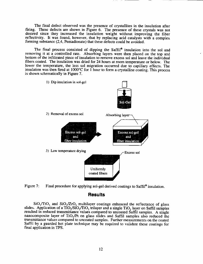
The final process consisted of dipping the Saffil ® insulation into the sol and
removing it at a controlled rate. Absorbing layers were then placed on the top andbottom of the infiltrated piece of insulation to remove excess sol and leave the individual
fibers coated. The insulation was dried for 24 hours at room temperature or below. Thelower the temperature, the less sol migration occurred due to capillary effects. Theinsulation was then fired at 1000°C for 1 hour to form a crystalline coating. This processis shown schematically in Figure 7.
1) Dip insulation in sol-gel 5
2) Removal of excess sol Absorbing
3) Low temperature drying sol
Figure 7: Final procedure for applying sol-gel derived coatings to Saffil ® insulation.
Results
SiO2/TiO 2 and SiOJZrO 2 multilayer coatings enhanced the reflectance of glassslides. Application of a TiO2/SiO2/TiO2 trilayer and a single TiO 2 layer on Saffil samplesresulted in reduced transmittance values compared to uncoated Saffil samples. A singlenanocomposite layer of TiO2/Pt on glass slides and Saffil samples also reduced thetransrmttance values compared to uncoated samples. Further measurements on the coatedSaffil by a guarded hot plate technique may be required to validate these coatings forfinal application in TPS.
12

Reflectance Measurements on Glass Slides
Specular reflectance spectra from ZrO2/SiO 2 and TiO2/SiO 2 combinations wereobtained by FTIR spectroscopy. Specular reflectance was obtained as a function of wavenumber. Figure 8 shows the spectral characteristics of multilayer stacks formed byalternating 11 layers of SiO 2 and TiO 2 on a glass slide. The infrared region of thespectrum encompasses radiation with wavenumbers ranging from about 12,800 to 10 cm -1(wavelengths from 0.78 to 1000 lxm). Since most of the blackbody radiant energy ofinterest occurs below wavenumbers of 2000 cm -_ (below wavelengths 5 ktm), themaximum wavenumber of interest shown on the figures is 2000 cm'. As shown in
Figure 8, the reflectance was increased by greater than 100% in the infrared (IR) regionby the application of sol-gel multi-layer TiOJSiO 2 coatings. The measured totalreflectance values for ZIO2/SiO 2 (11 layer stack), TiO2/SiO 2 (11 layer stack), and TiO 2-SiO 2 (21 layer stack) are 16.65%, 18.30%, and 26.30%, respectively at a wavelength ofwavenumber of 4000 cm -I (wavelength 2.5 ktm). In general, the reflectance of the
ZrO2/SiO 2 combination was observed to be smaller than that of the TiO2/SiO 2combination for an equal number of total layers. Also, it has been observed that thereflectivity increases with an increase in the total number of layers for wavenumbers lessthan 2000 cm-1.
28.57
Reflectance,%
14.29__I_'_ "_-" f 11TiO2 - SiO2 layers
.... _---__._.__ _ Uncoated "_-----__"
0.0 ' ' J _ ' ' ' ' ' '4000 3800 3600 3400 3200 3000 2800 2600 2400 2200 2000
Wavenumber, cmd
Figure 8: Spectral characteristics of uncoated and coated glass slide.
Transmittance Measurements on Saffil Samples
The initial approach to obtaining a reflective coating was to coat the fibers withalternating layers of a high and a low refractive index coating. The two materials usedfor the coatings were TiO 2 and SiO 2. To evaluate the effectiveness of the coating, a thinply of Saffil ® (-0.64 mm thick) was coated with a reflective coating. Six specimens werecoated with varying coatings, and along with two uncoated controls (one heat treated likethe coated samples and one not heat treated), were sent to NASA Lewis for testing. Theeight samples and their respective weight gains are shown in Table 5. The last twosamples, with 25 and 36 % weight gain, are obviously unacceptable.
At NASA Lewis, the transmittance of each specimen was determined. Thespecimen was placed between a black body source at 1075°C (1966°F) and aspectrometer. The transmittance is defined as the ratio of the radiation intensity detectedat the spectrometer with the sample between the blackbody and the spectrometer and theradiation intensity with no sample between the blackbody and the spectrometer. Thespecimen was approximately 50°C, and thus contributed little emission to thetransmittance. A chopper was used to assist in the measurements.
13

Table5: SamplesTestedfor TransmittanceandRespectiveWeightGains
Sample % weisht _ain
Uncoated 0Uncoated and heated treated 0
TiO 2 1.19TiO 2 4.34TiO 2 7.9TiO2/SiOJ TiO 2 4.7TiO2/SiOJ TiO 2 25
TiO2/SiOz/TiO2/SiOz/TiO 2 36
The results of the tests are shown in Figure 9 for the eight specimens. Two controlswere used. One was Saffil ® as delivered by the manufacturer. The second control wasuncoated Saffil ® that had been exposed to the same heat treatment cycles as the coatedfibers. The transmittance was nearly identical for the two cases, and therefore only theheat treated control is shown here. The six specimens with coated fibers permitted an
evaluation of the number of layers of coating and the thickness of the coating. FromFigure 9, it is evident that the transmittance of Saffil ® is highly wavelength dependent,and for the 0.64-mm-thick sample tested here, is approximately 2% below 7 ktm, 10-30%between 7 and 11 _m, and 0% above 11 lain. Coating the fibers provided a significantdecrease in the transmittance between 7 and 11 I.tm.
0.3
0.2
Transmittance,%
0.1
Figure 9:
0.0
0
TiO2, 4.34 % wt. gainUncoated
TiO2, 1.19% wt. gain
TiO2, 7.9% wt. gain
TiO2/SiO2/TiO2,
4.7% wt. gain
TiO2/SiO2/TiO2,
25% wt. gain
36% wt. gain
5 10 15
Wavelength, microns
Transmittance of coated and uncoated Saffil ® as a function of wavelength
14

The effect of the reflective coating canbestbe seenby comparingthe curves inFigure9 for a singlelayer of Tit 2(1.19%,4.34%,and7.9%weightgain) anda tri-layerof TiOJ SiOJ Tit 2. As would beexpected,increasingthemassin theonelayer coatingdecreasesthetransmittance.(Thetransmittancefor the 1.19%and4.34%weightgainareoppositetheexpectedtrends,but this is likely dueto measurementuncertainties,suchasvariationsin samplethickness.) Thetri-layer coatingwith a 4.7% weight gain showsasignificantreductionin transmittanceversusthesinglelayercoatingof approximatelythesamemass. Increasingthemassgainof the singlelayer coatingto 7.9%still resultsin ahighertransmittancethanfor thetri-layer with a 4.7%weightgain. Thetri-layer coatingwith a4.7% weight gain appearsto be the optimum coatingof the onestested. Theseresults seemto indicate that the approachof increasingthe reflectanceby alternatinglayersof high and low indexof refractionmaterialscandecreasetheamountof thermalradiationtransmittedthroughfibrousinsulation.
The diffuse, or hemispherical, transmittance of coated and uncoated Saffil®insulation was determinedat NASA Langley to be between0.45 and 1.9 I.tm,and theresultsare shownin Figure 10. An integrating spherewasusedto obtain the diffusetransmittanceby collecting all of thescatteredradiation. This is in contrastto specularmeasurementswhereonly radiationthat travelsstraightthroughthesampleis measured.The coatedsample is the tri-layer coated samplewith a 4.7% weight gain that wasevaluatedat NASA Lewis. Thediffuse transmittanceshowsasignificantreductionin thelow wavelengthrangedueto coatingthefibers.
50 -
40
30
Transmittance,%
20
10
I I ' |
0.0 0.5
0 | • I | | | | J I 0 , ,
1.0 1.5 2.0
Wavelengh, _tm
Figure 10: Diffuse transmittance of coated and uncoated Saffil ® insulation.
Diffuse transmittance measurements were also made on the catalytic grade of
Saffil ®. The catalytic grade contains porous fibers, and thus has a lower density. Inaddition, the maximum use temperature (with no significant shrinkage) is 1300°C, downfrom 1700°C for the conventional LD matte material. Three samples of Saffil ® were
15

coated. Two were coated with a tri-layer of Tit2/Sit2/Tit 2, and one was coated with asingle layer of Tit 2. The two samples that were coated with the tri-layer were coatedwith the same coating, and thus should have similar attenuation effects on the thermal
radiation. The transmittance of the coated and uncoated catalytic grade Saffil _ is shownin Figure 11 between 0.45 and 1.9 larn.
40
30
Transmittance,%
20
10
0
0.0
m i |
0.5 1.0 1.5 2.0
Wavelength, _tm
Figure 11: Diffuse transmittance of coated and uncoated catalytic grade Saffil ®.
The thickness of the samples was different for each specimen, and thus thetransmittance data alone is not sufficient to interpret the results. The extinctioncoefficient takes into account the transmittance and the thickness, and can thus be used tocompare the different samples. Table 6 shows the extinction coefficient for each of the
four Saffil ® specimens. The extinction coefficient of the Tit 2 coated and uncoatedsample are similar, indicating that the single layer coating provides negligible benefit.The two samples with the tri-layer provided significant benefit compared to the uncoatedSaffil ®. Though the transmittance is different for the two coated samples, the extinctioncoefficients are similar. The extinction coefficients shown here are for diffuse radiation
and are a function of the wavelength at which the measurements are made.
Finally, a thicker piece of Saffil ®, approximately 0.25-in. thick, was coated to
determine the effectiveness of applying the coating uniformly through the thickness.After the sample was coated, layers were peeled apart and the transmittance was
measured. A sketch of the sample and the individual layers is shown in Figure 12. All ofthe layers except layer 2 were approximately the same thickness.
16

Table6: ExtinctionCoefficientof CoatedandUncoatedCatalyticGradeSaffil®
Coating Avg. Transmittance Thickness,m ExtinctionCoefficient,m-1
Uncoated 0.19 1.85x 10⁻³ 895
TiO 2 0.1 2.67 x 10 -3 863TiO2/SIO2/TiO 2
Sample 1 0.16 1.47 x 10 -3 1244
Sample 2 0.27 1.14 x 10 -3 1145
0.25 in.
Figure 12: Sketch of the thick piece of coated Saffil ®.
Layer 1Layer 2
Layer 3a
Layer 3b
Layer 4
Layer 5
Layer 6
50f Layer 3a
40 I Layer_Transmittance,
% 30 |Layer5 --1 "_,,o,.1"_ - _ r_
Layer 2
20
10
0 1[ , . . ___ Layer6 L _ . . ,
0.0 0.5 1.0 1.5 2.0
Wavelength, btm
Figure 13: Diffuse transmittance of individual layers of coated Saffil ®.
The diffuse transmittance of the different layers is shown in Figure 13 between 0.45
and 1.9 }.tm for the seven different layers. As in the previous case, the transmittance of
the Saffil ® is dependent on the sample thickness. Table 7 shows the extinction coefficientof each layer. The extinction coefficient accounts for the sample thickness, and thus can
17

be used to evaluate the uniformity of the coating through the thickness. The uncertaintyin the extinction coefficient calculations is quite large due to the large uncertainty in thethickness measurement.
Table 7: Extinction Coefficient of Coated Saffil ®
Lancer Av_. Transmittance Thickness*, m Extinction Coefficient, m-1
1 0.27 8.89 x 10 -4 1473
2 0.27 1.78 x 10 -3 736
3a 0.37 8.89 x 10 -4 1118
3b 0.25 8.89 x 10 -4 1559
4 0.36 8.89 x 10 -4 1149
5 0.35 8.89 x 10 -4 1181
6 0.24 8.89 x 10 -4 1605
* Thickness measurements contain large uncertainties.
No pattern or trend appears to be present in the extinction coefficient values. Onemight expect the outer layers to be coated with heavier coatings and the inner layers withless coating, resulting in low extinction coefficients in the inside and high extinctioncoefficients on the outside layers. However, the transmittance measurements do notindicate a clear distinction between inner and outer layers of Saffil ®.
Figure 14: SEM image of Saffil ® insulation coated with TiO 2.
The appearance of fibrous insulation coated with TiO 2 was investigated using ascanning electron microscope (SEM). The analysis revealed that the Saffil ® fibers wereuniformly coated with TiO 2 over most (approximately 95%) of the fiber surface area.
18

Uncoated areas appeared to be due to fiber touching. Such defects are unavoidable due tothe nature of the substrate and are shown in Figure 14.
Nanocomposite Reflective Coatings
The incorporation of fine noble metallic particles into a ceramic matrix has beenknown to bring about enhanced optical properties of matrix materials [19-20]. TiO 2 (Pt)composites were prepared by mixing an alkoxide of titanium and platinum complex. Theincorporation of Pt into TiO 2 matrix followed by thermal treatment at 650°C resulted in adramatic change in the optical properties.
The transmissivity of quartz slides and Saffil ® insulation coated with single layers
of TiO 2 and TiO2(Pt) was investigated using FTIR techniques. The results revealed thatTiO2(Pt ) coatings reduced the transmissivity of the quartz slide approximately 20%. Acoating containing TiO 2 did not have as great an effect on the transmissivity. Saffil ®
insulation coated with TiO2(Pt) also resulted in a decrease in transmissivity comparedwith uncoated insulation. However, these measurements are complicated by densityvariations throughout a sample of Saffil ® insulation. These variations have been found to
lead to a wide range in the measured transmissivity of samples measured at various pointson the sample. Efforts to eliminate this problem involved the use of a special sampleholder which allowed the sample to be measured at the same point on the sample before
and after coating. These attempts drastically decreased the variability in themeasurements, but not to a level where these results can be taken qualitatively.
Specimens Coated for Conductivity Measurements
Saffil samples 4 in. x 4 in. x -0.2" thick were prepared for guarded hot platemeasurements. Three different coatings were selected for thermal evaluation using the
guarded hot plate technique. These coatings are TiO2(Pt), TiO 2, and TiO2/SiOJTiO 2.Coatings were applied on the fibrous Saffil specimens according to the proceduredescribed earlier. The edges of the samples were trimmed to avoid edge effects due tocoating in thermal measurements. The weight gain due to coating materials weremeasured and the results are presented in Table 8.
Table 8. Test Matrix for Guarded Hot Plate Measurements.
Coating Type % Weight Gain No. Specimens
Uncoated 0.0 2
TiO 2 3.8 2TiO2(Pt ) 9.3 2TiO2/SiO2/TiO2 14.5 2SiO 2 7.0 2
Conclusions
The objective of this research was to determine if reflective coatings could beapplied to a fibrous insulation and what effect they would have on the thermalconductivity of the insulation. Application of a coating onto fibrous insulation could notbe done using conventional techniques due to the complex nature of the substrate. As aresult, reflective coatings were developed using sol-gel techniques. It was found that sol-gel could be used to apply a coating to the individual fibers in Saffil ® insulation using a
19

procedure in which a sample was dipped in a sol, had the excess sol removed by theapplication of an absorbing layer, dried at low temperature, and cured at 1000°C. SEMmeasurements confirmed that an effective coating had been applied to the fibers.Transmissivity measurements showed that the coating was effective in decreasing thetransmissivity of the insulation. However, uncertainty in this data was large. Futuremeasurements using ellipsometry and a guarded hot plate will determine the index ofrefraction of the coatings and the thermal conductivity of the insulation to answerexisting questions on the validity of this technique.
References
° Gorthala, R.; Harris, K. T.; Roux, J. A., and McCarty, T. A.: Transient Conductive,Radiative Heat Transfer Coupled with Moisture Transport in Attic Insulations, J. ofThermophysics and Heat Transfer, Vol. 8, No. 1, pp. 125-132, 1994.
. Tong, T. W.; Yang, Q. S.; and Tien, C. L.: Transactions of the ASME, Vol. 105,(1983) pp. 76-81.
. Mathes, R.; Blumenberg, J.; and Keller, K.: Radiative Heat Transfer in InsulationsWith Random Fibre Orientation, International J of Heat and Mass Transfer, Vol. 33,No. 4, pp. 767-770, 1990.
. Lee, S. C.: Dependent vs. Independent Scattering on Fibrous CompositesContaining Parallel Fibers, J. of Thermophysics and Heat Transfer, Vol. 8, No. 4,pp. 641-646, 1994.
. Cunnington, G. R.; Tong, T. W.; and Swathi, P. S.: Angular Scattering of RadiationFrom Cylindrical Fibers, AIAA Thermophysics, Plasmadynamics and LasersConference, AIAA-88-2721, 1988.
, Verschoor, J. D.; Greebler, P.; and Manville, N. J.: Heat Transfer by Gas
Conduction and Radiation in Fibrous Insulation, J. of Heat Transfer, Vol. 74, pp.961-968, 1952.
, Tong, T. W.; Swathi, P. S.; and Cunnington, G. R. Jr.: Journal of ThermalInsulation, Vol. 11, (1994) pp. 7 - 31.
° Grunert, W. E.; Notaro, F.; and Reid, R. L.: Opacified Fibrous Insulations, AIAA4th Thermophysics Conference, June 16-18, 1969, AIAA-69-605, 1969.
. Tong, T. W.; Swathi, P. S.; and Cunnington, G. R. Jr.: Reduction of Radiative HeatTransfer in Thermal Insulations by Use of Dielectric Coated Fibers, Int. Comm.Heat Mass Transfer, Vol. 16, (1989).
10. Wang, K.Y.; Kumar, S.; and Tien, C. L.: Radiative Transfer in Thermal Insulationsof Hollow and Coated Fibers, J. Thermophysics and Heat Transfer, Vol. 1, No. 4,(1987).
11. Pettyjohn, R. R.: Thermal Conductivity Measurements on the Fibrous Insulation
Material, Thermal Conductivity Proceedings of the Seventh Conference, (1967).
20

12.
13.
14.
15.
16.
17.
18.
19.
20.
21.
Siegal, R. and Spuckler, C. M.: Refractive Index Effects on Radiation in anAbsorbing,Emitting, andScatteringLaminatedLayer,Transactionsof the ASME,Vol. 115,(1993).
Siegal, R. and Spuckler, C. M.: Effect of Index of Refraction on RadiationCharacteristicsin aHeatedAbsorbing,Emitting, andScatteringLayer, JournalofHeatTransfer,Vol. 114,(1992).
Siegel, R.: Transient Heat Transfer in a SemitransparentRadiating Layer withBoundaryConvectionand SurfaceReflections,InternationalJournalof Heat andMassTransfer,Vol. 39,No. 1,pp.69-79, 1996.
Siegel, R: Refractive Index Effects on Transient Cooling of a SemitransparentRadiatingLayer, Journalof ThermoPhysicsand HeatTransfer,Vol. 9, No. 1, pp.55-62,1995.
Ohring,M.: TheMaterialsScienceof Thin Films,AcademicPressInc., (1992).
Chopra,K. I.: Thin Film Phenomena, McGraw-Hill, New York (1969).
Kingery, W. D. ; Bowen, H. K.; and Uhlmann, D. R.: Introduction to Ceramics, 2nded., Wiley, New York, (1976) pp. 662.
Burkhart, T.; Menning, M. ; Schmidt, H.; and Licciulli, A.: Nano Sized Pd Particlesin a SiO 2 Matrix by Sol-Gel Processing, Mat. Res. Soc. Symp. Proc., Vol. 346,(1994)
Arnold, G. W. and Borders, J. A.: Journal of Applied Physics, vol. 48. p. 1488,1977.
Brinker, C. J.; and Scherer, G.W.: Sol-Gel-Glass: I. Gelation and Gel Structure, J.
Non-Cryst. Solids, Vol. 70, (1985 panel).
21

REPORT DOCUMENTATION PAGE FormAo_rov,_OMB No. 0704-0188
i=_mi¢ :mooning mxc4m rot _ms co#ecmsn o1 infom_tmm'_ is enomitla to m,w'aql t ,out pm'nmo_nse, inc_cung o_, m'ne m.r,m_mmng _ slWm'mg emmm'_,:;mUl sources.
gamemg am= rnmmmrungmeoamnN_. __ __ c_,ec_'_ of _'_a_. Sendcm'nments,mgxnSngmisOtarm_ umnmeorwwomer u_lc_ofmm
¢oucoon ot ia/ormatmn. :mm.,m'xj suggestmns for reducing =Its lumen. _o Wlsn_ I"tmdClUaUm,rs _ Dimc=_me rot Int'_fmalmom Ommmons and _ 1215
Higmv, Bv. Suite t204 Ar'm_on. VA 222_2-430?_ an_ to ."he Gfflcl of Management ana _u_;'et. Pao_ R_c:_n ="mec_ (0704-01881. Wumlt_0:.n. _ 20503.
Oaws
1. AGENCY USE CNL'." (LBave oa,,lnx) 2. REPORTDATE 3.REPORTTYPEANDDA1"ESCOVERED
August 1997 Contractor Report
4. TITLE AND SUBTITI._
Reflective Coating on Fibrous Insulation for ReducedHeat Transfer
s. AUTHOR(S)Derek D. Hass, B. Durga Prasad, David E. Glass,and Karl E. Wicdemann
7. PERFORMINGORGANIZATIONNAME(S)ANDADDRESS(F.S)
Analytical Services & Materials, Inc.107 Research Drive
Hampton, VA 23666-1340
9. SPONSORING I MCNffOPJNG AGENCY NAME(S)AND A_F.SS(ES)
National Aeronautics and Space AdministrationLangley Research CenterHampton, VA 23681-0001
5. FUNDING NUMBERS
2 NAS1-1 9708
WU 242-33-0 ]
8. PF.RFORMING ORGANIZATIONREPORT NUMBER
AS&M-MM6-97-01
10. SPONSORING / MONITORINGAGENCY REPORT NUMBER
NASA CR-201733
11. SUPPt.F..MENTARY NOt_
Langley Technical Monitor: Stephen J. Scotti
12a. i)k,__HII_UTION / AVAILABIL.rrY STA_I_AENI"
Unclassified Unlimited
Subject Category 34
12b. DISTRIBUTION CODE
13. ABSTRACT (Mamunum 200 wor_s)
Radiative heat transfer through fibrous insulation used in thermal protection
systems (TPS) is significant at high temperatures (1200°C). Decreasing the
radiative heat transfer through the fibrous insulation can thus have a major
impact on the insulating ability of the TPS. Reflective coatings applied directlyto the individual fibers in fibrous insulation should decrease the radiative heat
transfer leading to an insulation with decreased effective thermal conductivity.
Coatings with high infrared reflctance have been developed using sol-gel techniques.
Using this technique, uniform coatings can be applied to fibrous insulation
without an appreciable increase in insulation weight or density. Scanning electron
microscopy, Fourier Transform infrared spectroscopy, and ellipsometry have been
performed to evaluate coating performance.
14. SUBJECT TERMS
Sol-gel costings, Fibrous insulation, radiation heat transfer
15. NUMBER OF PAGES
24
16. PRICE CODE
A03
17. SECURITY CLAS3;FICATION
OF REPORT
Unclassified
18. SECURITY CLASS|F1C.I,'RONOF THIS PAGE
Unclassified
19. SECURITY CLASS;F:,CATION
OF ABSTRACT,
Unclassified
20. L_MITA'I'SONOFABSTRACT
Unlimited
NSN 7_,_G-.31-2_C-._5,30 StanOar,_ Form 298 (Rev 2-8.c_
Presc_beO _y ANSI SI '_. Z_9-_82_8-102