pow-r-commandtm (prc tm) 100 - eaton
TRANSCRIPT
April 2003
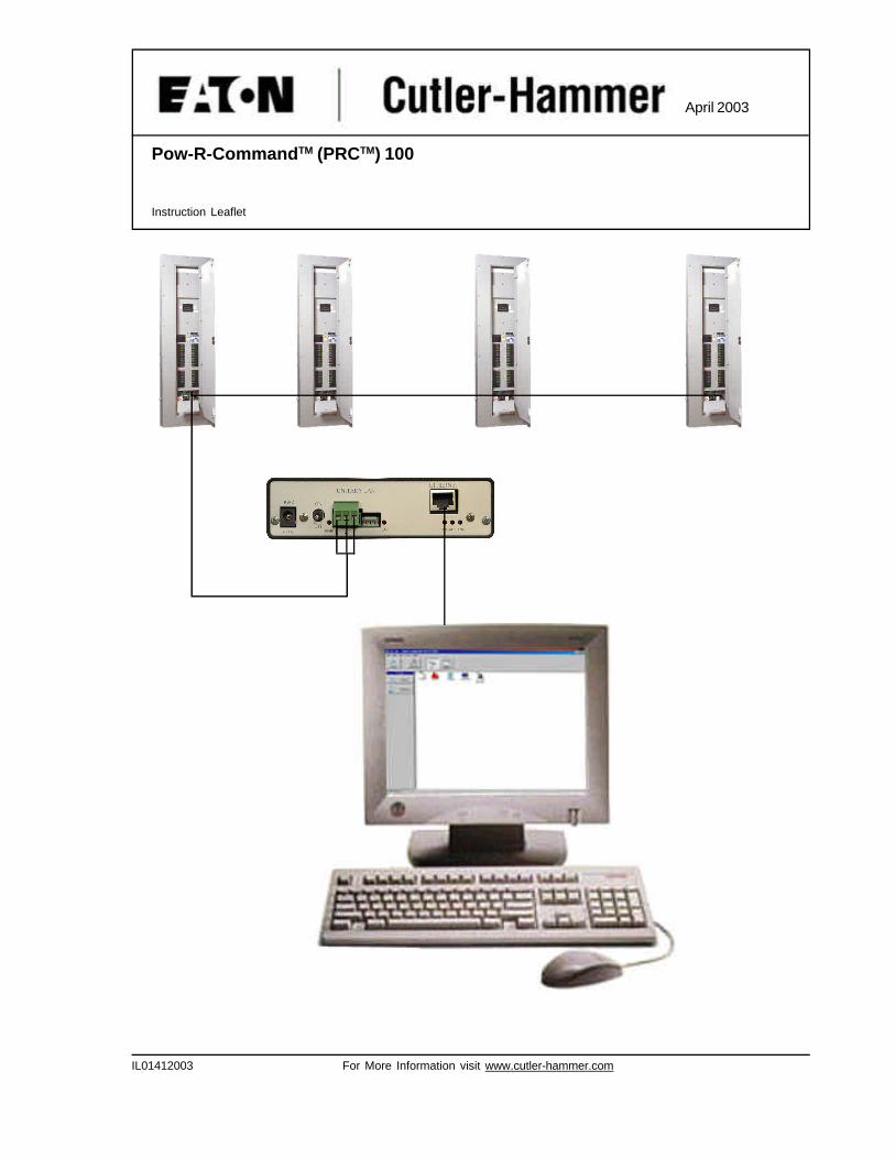
Pow-R-CommandTM (PRCTM) 100
Instruction Leaflet
IL01412003 For More Information visit www.cutler-hammer.com
Installation LeafletPage 2 Effective: April 2003
Pow-R-Command 100
IL01412003 For More Information visit www.cutler-hammer.com
Pow-R-Command System
Installation Leaflet
Notes and Warnings
-Read this guide completely and carefully prior to any installation. Failure to follow the instructions or the prescribed procedures may cause severe injury or death and/or damage to the equipment.
-All installation and service must be performed by qualified personnel or service technicians. Keep this guide available to those responsible for installation, programming, operation, and maintenance of the system.
-All installation and wiring information contained herein is based on industry-accepted standards and practices. This information is not meant to conflict with or overrule any applicable codes or ordinances. If any conflicts exist, please contact your Cutler-Hammer Representative before proceeding with the installation.
-USE EXTREME CAUTION WHEN OPERATING THE SYSTEM. DANGEROUS VOLTAGES MAY EXIST INSIDE THE UNITS. Failure to follow any or all warnings and instructions contained herein may cause severe injury or death and/or damage to the equipment.
-Panels are shipped from the factory with the electronic boards installed and tested. Many of the electronic components may be sensitive to static electricity. Do not handle electronic parts without proper electrostatic protection.
-Document all wiring, device termination and locations. This information will be required for system start up and programming.
-Under no circumstances switch on the power to the electronics during or after installation. Power up, programming and system configuration should be performed by qualified personnel during the system start up.
-The instructions and prescribed procedures in this Installation Guide do not purport to cover all possible contingencies, which may arise during installation, and all details and variations of the system. If further information is desired by regarding the particular installation of the system, please contact your Cutler-Hammer Representative.
Installation LeafletPage 3 Effective: April 2003
Pow-R-Command 100
IL01412003 For More Information visit www.cutler-hammer.com
Table Of Contents
SECTION 1: MOST COMMON CONFIGURATIONS AND DESCRIPTIONS 41-1 POW-R-COMMAND PANELBOARDS 41-2 EXPANSION/CONTROL CABINET 51-3 RELAY PANEL 5
SECTION 2: POWER SUPPLY TERMINATION 62-1 PANELBOARD 62-2 RELAY PANEL, EXPANSION/CONTROL CABINET 6
SECTION 3: LOW-VOLTAGE TERMINATION 73-1 PANELBOARD 73-2 RELAY PANEL, EXPANSION/CONTROL CABINET 83-3 CONTROLLABLE BREAKER REMOTE TERMINATION 9
SECTION 4: APPLICATION SPECIFIC CARD TERMINATION 104-1 UNIVERSAL SYSTEM CONTROLLER 104-2 SWITCH OVERRIDE CONTROLLER 104-3 UNIVERSAL I/O MODULE 114-4 LOW-VOLTAGE INPUTS & OUTPUTS 114-5 LOW-VOLTAGE WIRING APPLICATION 13
SECTION 5: NETWORK TERMINATION 215-1 NETWORK TERMINATION 225-1.1 PANELBOARD 225-1.2 RELAY PANEL, EXPANSION/CONTROL CABINET 235-2 7X EXPANSION CHASSIS NETWORK TERMINATION 245-3 NETWORK REPEATER 25
SECTION 6: PERSONAL COMPUTER TERMINATION 266-1 NIB TO PC CONNECTION 266-2 ETHERNET SERVER TO PC CONNECTION 266-3 NIB TO MODEM CONNECTION 276-4 ETHERNET SERVER TO ETHERNET WITH BACKUP CONNECTION 27
SECTION 7: CONTROLLER ADDRESSING 287-1 ADDRESSING USING A PC 287-2 ADDRESSING USING A POCKET PC TEST TOOL 30
Installation LeafletPage 4 Effective: April 2003
Pow-R-Command 100
IL01412003 For More Information visit www.cutler-hammer.com
SECTION 1: MOST COMMONCONFIGURATIONS ANDDESCRIPTIONS
Cutler-Hammer offers a full line of differenttypes of chassis and configurations forPow-R-Command 100 applications. Mostcommon configurations are describedbelow.
1-1 POW-R-COMMAND PANELBOARD
Pow-R-Command 100 Panelboard can comein two main configurations:
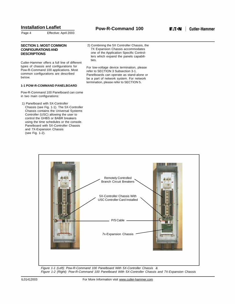
1) Panelboard with 5X-ControllerChassis (see Fig. 1-1). The 5X-ControllerChassis contains the Universal SystemsController (USC) allowing the user tocontrol the GHBS or BABR breakersusing the time schedules or the console.Panelboard with 5X-Controller Chassisand 7X-Expansion Chassis(see Fig. 1-2).
2) Combining the 5X Controller Chassis, the7X Expansion Chassis accommodatesone of the Application Specific Control-lers which expand the panels capabili-ties.
For low-voltage device termination, pleaserefer to SECTION 3 Subsection 3-1.Panelboards can operate as stand-alone orbe a part of network system. For networktermination, please refer to SECTION 5.
Remotely ControlledBranch Circuit Breakers
5X-Controller Chassis WithUSC Controller Card Installed
P/S Cable
7x-Expansion Chassis
Figure 1-1 (Left): Pow-R-Command 100 Panelboard With 5X-Controller Chassis &Figure 1-2 (Right): Pow-R-Command 100 Panelboard With 5X-Controller Chassis and 7X-Expansion Chassis
Installation LeafletPage 5 Effective: April 2003
Pow-R-Command 100
IL01412003 For More Information visit www.cutler-hammer.com
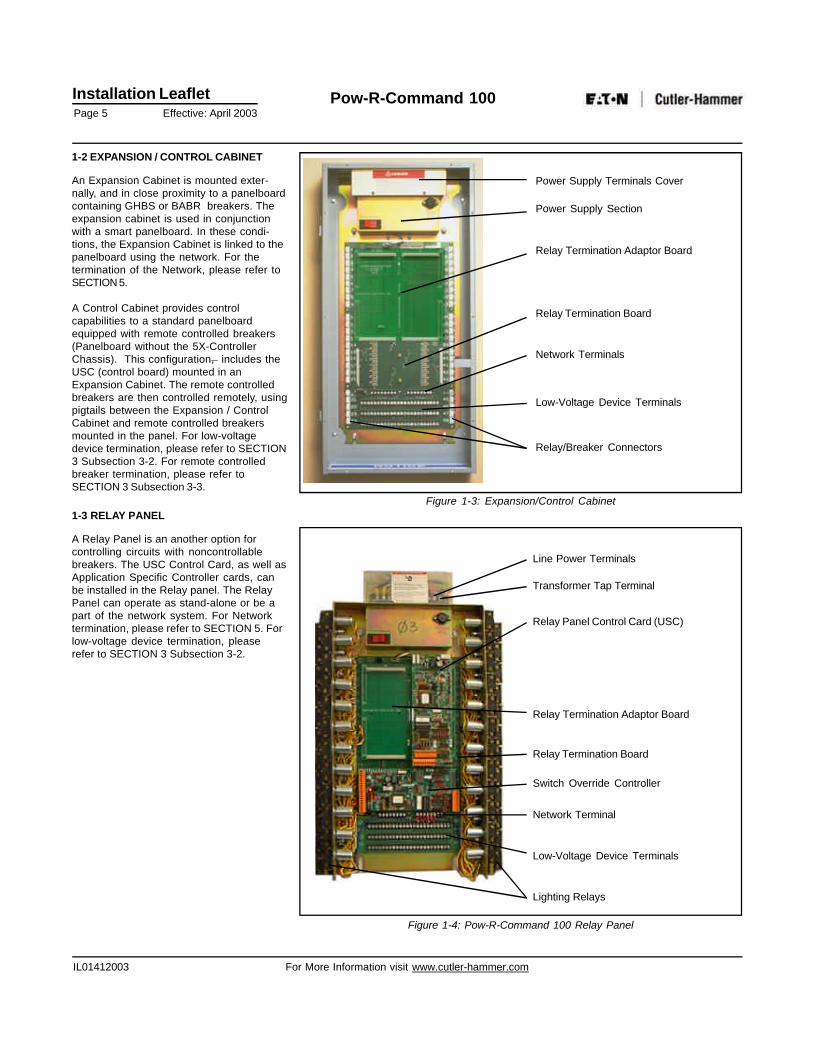
1-2 EXPANSION / CONTROL CABINET
An Expansion Cabinet is mounted exter-nally, and in close proximity to a panelboardcontaining GHBS or BABR breakers. Theexpansion cabinet is used in conjunctionwith a smart panelboard. In these condi-tions, the Expansion Cabinet is linked to thepanelboard using the network. For thetermination of the Network, please refer toSECTION 5.
A Control Cabinet provides controlcapabilities to a standard panelboardequipped with remote controlled breakers(Panelboard without the 5X-ControllerChassis). This configuration, includes theUSC (control board) mounted in anExpansion Cabinet. The remote controlledbreakers are then controlled remotely, usingpigtails between the Expansion / ControlCabinet and remote controlled breakersmounted in the panel. For low-voltagedevice termination, please refer to SECTION3 Subsection 3-2. For remote controlledbreaker termination, please refer toSECTION 3 Subsection 3-3.
1-3 RELAY PANEL
A Relay Panel is an another option forcontrolling circuits with noncontrollablebreakers. The USC Control Card, as well asApplication Specific Controller cards, canbe installed in the Relay panel. The RelayPanel can operate as stand-alone or be apart of the network system. For Networktermination, please refer to SECTION 5. Forlow-voltage device termination, pleaserefer to SECTION 3 Subsection 3-2.
Power Supply Terminals Cover
Power Supply Section
Relay Termination Adaptor Board
Network Terminals
Low-Voltage Device Terminals
Relay/Breaker Connectors
Figure 1-3: Expansion/Control Cabinet
Line Power Terminals
Transformer Tap Terminal
Relay Panel Control Card (USC)
Relay Termination Adaptor Board
Relay Termination Board
Network Terminal
Switch Override Controller
Low-Voltage Device Terminals
Lighting Relays
Figure 1-4: Pow-R-Command 100 Relay Panel
Relay Termination Board
Installation LeafletPage 6 Effective: April 2003
Pow-R-Command 100
IL01412003 For More Information visit www.cutler-hammer.com
SECTION 2: POWER SUPPLYTERMINATION
2-1 PANELBOARD
Panelboards are shipped with theController’s Chassis power supply for theelectronics terminated to the correctvoltage. There is no need for the personnelinstalling the panel to supply connections tothe power supply of the 5X-ControllerChassis or 7X-Expansion Chassis. Pleaseverify that the panels supply voltagematches the voltages specified on the labelof the panel. On the left side of the 5X-Controller Chassis find the wires feedingprimary side of the power supply. If wire isnot used for the application, it shouldcontain isolating cap. Wires are color codedas follows:
- RED 120VAC- YELLOW 277VAC- BROWN NEUTRAL- GREEN GROUND
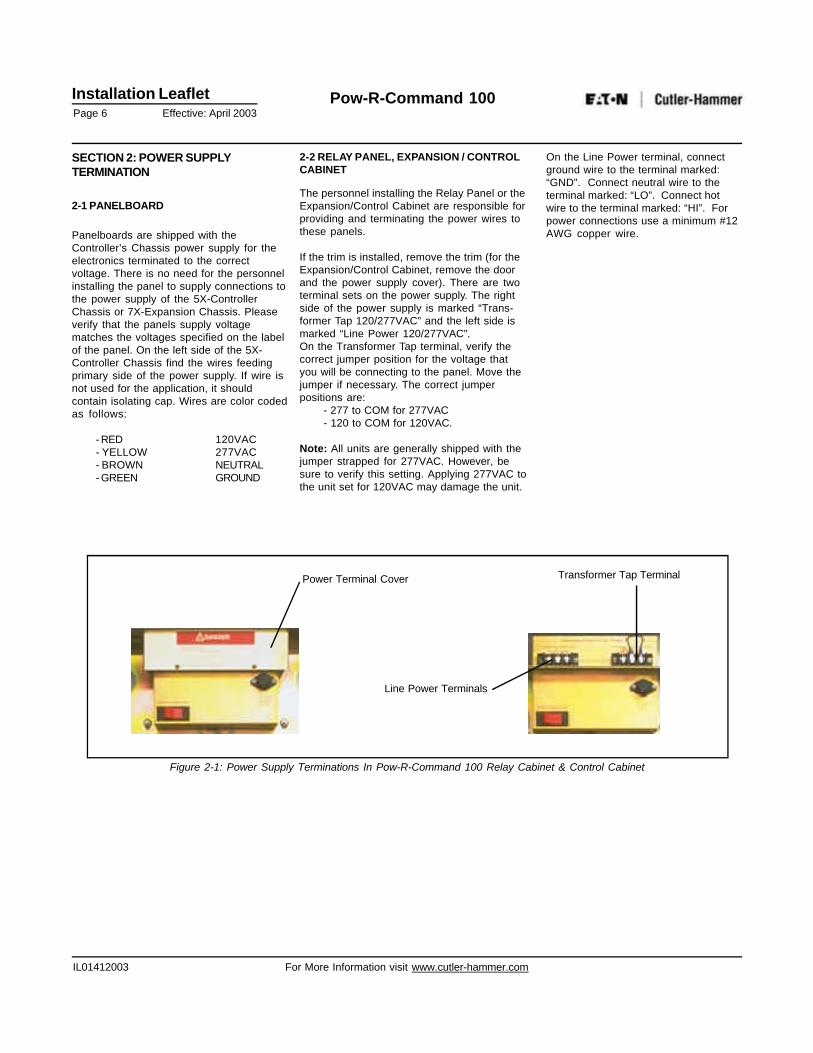
2-2 RELAY PANEL, EXPANSION / CONTROLCABINET
The personnel installing the Relay Panel or theExpansion/Control Cabinet are responsible forproviding and terminating the power wires tothese panels.
If the trim is installed, remove the trim (for theExpansion/Control Cabinet, remove the doorand the power supply cover). There are twoterminal sets on the power supply. The rightside of the power supply is marked “Trans-former Tap 120/277VAC” and the left side ismarked “Line Power 120/277VAC”.On the Transformer Tap terminal, verify thecorrect jumper position for the voltage thatyou will be connecting to the panel. Move thejumper if necessary. The correct jumperpositions are:
- 277 to COM for 277VAC- 120 to COM for 120VAC.
Note: All units are generally shipped with thejumper strapped for 277VAC. However, besure to verify this setting. Applying 277VAC tothe unit set for 120VAC may damage the unit.
On the Line Power terminal, connectground wire to the terminal marked:“GND”. Connect neutral wire to theterminal marked: “LO”. Connect hotwire to the terminal marked: “HI”. Forpower connections use a minimum #12AWG copper wire.
Power Terminal Cover
Line Power Terminals
Transformer Tap Terminal
Figure 2-1: Power Supply Terminations In Pow-R-Command 100 Relay Cabinet & Control Cabinet
Installation LeafletPage 7 Effective: April 2003
Pow-R-Command 100
IL01412003 For More Information visit www.cutler-hammer.com
SECTION 3: LOW-VOLTAGE DEVICETERMINATION
All open areas in the panels are consideredas low-voltage/class-2 termination areas.No voltages above 28VAC are permitted inthis area. Inputs are designed so that onlydry contact devices are accepted.NO EXTERNAL VOLTAGES SHOULD BEAPPLIED TO THE LOW-VOLTAGETERMINAL BLOCKS. ALL NECESSARYPOWER IS PROVIDED BY THE PANEL.Low-voltage devices should be terminatedusing a minimum #22AWG twisted pairwire. Shielding is generally not required.Low-voltage device cables should not belocated in the same conduit with the high-voltage load wires. Be sure the wire typeyou use is rated properly, especially forplenum or hazardous applications.
3-1 PANELBOARD
In most cases, Application Specific Cardswill be located in the 7X Expansion Chassisinstalled in the panel. Power supply andNetwork connections will be provided in thefactory.
In rare case of the 7X-Expansion Chassislocated externally to the panel, the networkcable and the power supply cable shouldbe installed between the panel and the 7X-Expansion Chassis. For Network termina-tion, please refer to SECTION 5.
The personnel installing the panel areresponsible for providing and terminationwiring of all external low-voltage devices.Use knockouts provided on the bottom andsides of the chassis to enter the low-voltage termination area.
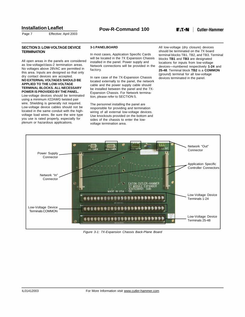
All low-voltage (dry closure) devicesshould be terminated on the 7X boardterminal blocks TB1, TB2, and TB3. Terminalblocks TB1 and TB3 are designatedlocations for inputs from low-voltagedevices—numbered respectively 1-24 and25-48. Terminal block TB2 is a COMMON(ground) terminal for all low-voltagedevices terminated in the panel.
Network “Out”Connector
Power SupplyConnector
Network “In”Connector
Low-Voltage DeviceTerminals COMMON
Application SpecificController Connectors
Low-Voltage DeviceTerminals 1-24
Low-Voltage DeviceTerminals 25-48
Figure 3-1: 7X-Expansion Chassis Back-Plane Board
Installation LeafletPage 8 Effective: April 2003
Pow-R-Command 100
IL01412003 For More Information visit www.cutler-hammer.com
3-2 RELAY PANEL, EXPANSION/CONTROLCABINET
The Relay Panel and Expansion / ControlCabinet use the same Relay TerminationBoard for low-voltage (dry-contact) devicetermination.
A Relay Panel is used to control loadsdown-line from a breaker panel notequipped with controllable breakers. ARelay Panel is shipped from the factorywith the low-voltage side of the relaysterminated to the Relay Termination Board.Personnel installing the Relay Panel areresponsible for providing and terminatingwires to load side of the relays. Maximumwire size accepted by the relay terminals is#10AWG.
An Expansion / Control Cabinet is installedexternally to a breaker panel. The person-nel installing the above mentioned devicesare responsible for providing termination ofthe power supply, network, and all externallow-voltage devices. For power supplytermination, please refer to SECTION 2Subsection 2-2. For network termination,please refer to SECTION 5.Use bottom of the previously describedenclosure types to attach conduit andprovide access to the low-voltagetermination area.
Panels using Expansion Cabinet might ormight not contain 5X-Controller Chassis. Forpanels with a 5X-Controller Chassis, theExpansion Cabinet is used for ApplicationSpecific Controllers only. Only low-voltagedevices and network are terminated in theExpansion Cabinet. For panels notcontaining the 5X-Controller Chassis theadditional step of terminating the remotecontrolled breakers to the Control CabinetRelay Termination Board is required. Forremote controlled breaker termination,please refer to SECTION 3 Subsection 3-3.
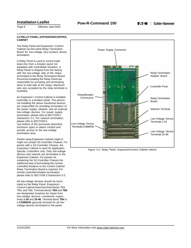
All low-voltage devices should be termi-nated on the Relay Panel, Expansion /Control Cabinet board terminal blocks TB3,TB4, and TB5. Terminal blocks TB3 and TB5are designated locations for inputs fromlow-voltage devices—numbered respec-tively 1-24 and 25-48. Terminal block TB4 isa COMMON (ground) terminal for all low-voltage devices terminated in the panel.
Power Supply Connector
Relay/BreakerConnectors
Controller Ports
Relay TerminationAdaptor Board
Network Terminal
Relay TerminationBoard
Low-Voltage DeviceTerminals 1-24
Low-Voltage DeviceTerminals 25-48
Low-Voltage DeviceTerminals COMMON
Figure 3-2: Relay Panel, Expansion/Control Cabinet Interior
Installation LeafletPage 9 Effective: April 2003
Pow-R-Command 100
IL01412003 For More Information visit www.cutler-hammer.com
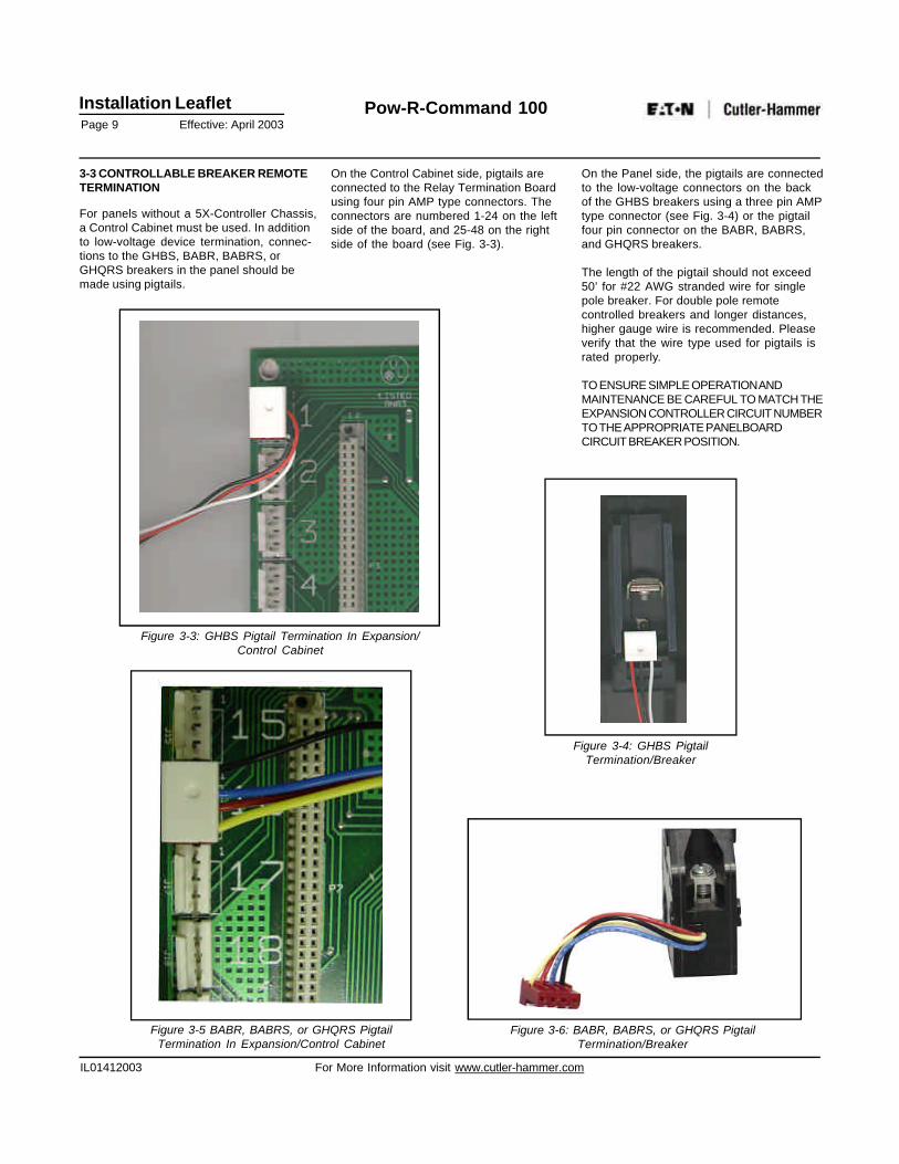
3-3 CONTROLLABLE BREAKER REMOTETERMINATION
For panels without a 5X-Controller Chassis,a Control Cabinet must be used. In additionto low-voltage device termination, connec-tions to the GHBS, BABR, BABRS, orGHQRS breakers in the panel should bemade using pigtails.
Figure 3-3: GHBS Pigtail Termination In Expansion/Control Cabinet
Figure 3-5 BABR, BABRS, or GHQRS PigtailTermination In Expansion/Control Cabinet
On the Control Cabinet side, pigtails areconnected to the Relay Termination Boardusing four pin AMP type connectors. Theconnectors are numbered 1-24 on the leftside of the board, and 25-48 on the rightside of the board (see Fig. 3-3).
On the Panel side, the pigtails are connectedto the low-voltage connectors on the backof the GHBS breakers using a three pin AMPtype connector (see Fig. 3-4) or the pigtailfour pin connector on the BABR, BABRS,and GHQRS breakers.
The length of the pigtail should not exceed50’ for #22 AWG stranded wire for singlepole breaker. For double pole remotecontrolled breakers and longer distances,higher gauge wire is recommended. Pleaseverify that the wire type used for pigtails israted properly.
TO ENSURE SIMPLE OPERATION ANDMAINTENANCE BE CAREFUL TO MATCH THEEXPANSION CONTROLLER CIRCUIT NUMBERTO THE APPROPRIATE PANELBOARDCIRCUIT BREAKER POSITION.
Figure 3-6: BABR, BABRS, or GHQRS PigtailTermination/Breaker
Figure 3-4: GHBS PigtailTermination/Breaker
Installation LeafletPage 10 Effective: April 2003
Pow-R-Command 100
IL01412003 For More Information visit www.cutler-hammer.com
SECTION 4: APPLICATION SPECIFICCARDS TERMINATION
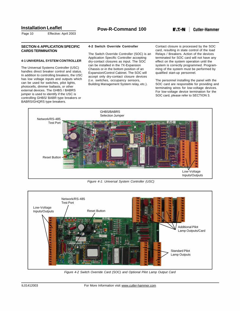
4-1 UNIVERSAL SYSTEM CONTROLLER
The Universal Systems Controller (USC)handles direct breaker control and status.In addition to controlling breakers, the USChas low voltage inputs and outputs whichcan be used for switches, pilot lights,photocells, dimmer ballasts, or otherexternal devices. The GHBS / BABRSjumper is used to identify if the USC iscontrolling GHBS/ BABR type breakers orBABRS/GHQRS type breakers.
4-2 Switch Override Controller
The Switch Override Controller (SOC) is anApplication Specific Controller acceptingdry-contact closures as input. The SOCcan be installed in the 7X-ExpansionChassis or in the bottom position of anExpansion/Control Cabinet. The SOC willaccept only dry-contact closure devices(i.e. switches, occupancy sensors,Building Management System relay, etc.).
Contact closure is processed by the SOCcard, resulting in state control of the loadRelays / Breakers. Action of the devicesterminated for SOC card will not have anyeffect on the system operation until thesystem is correctly programmed. Program-ming of the system must be performed byqualified start-up personnel.
The personnel installing the panel with theSOC card are responsible for providing andterminating wires for low-voltage devices.For low-voltage device termination for theSOC card, please refer to SECTION 3.
GHBS/BABRSSelection Jumper
Network/RS-485Test Port
Reset Button
Low-VoltageInputs/Outputs
Figure 4-1: Universal System Controller (USC)
Standard PilotLamp Outputs
Additional PilotLamp Outputs/Card
Reset ButtonLow-VoltageInputs/Outputs
Network/RS-485Test Port
Figure 4-2 Switch Override Card (SOC) and Optional Pilot Lamp Output Card
Installation LeafletPage 11 Effective: April 2003
Pow-R-Command 100
IL01412003 For More Information visit www.cutler-hammer.com
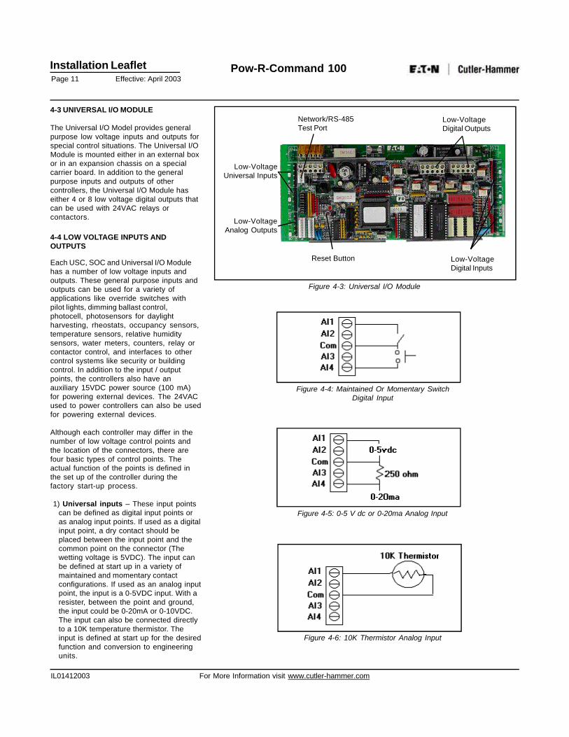
4-3 UNIVERSAL I/O MODULE
The Universal I/O Model provides generalpurpose low voltage inputs and outputs forspecial control situations. The Universal I/OModule is mounted either in an external boxor in an expansion chassis on a specialcarrier board. In addition to the generalpurpose inputs and outputs of othercontrollers, the Universal I/O Module haseither 4 or 8 low voltage digital outputs thatcan be used with 24VAC relays orcontactors.
4-4 LOW VOLTAGE INPUTS ANDOUTPUTS
Each USC, SOC and Universal I/O Modulehas a number of low voltage inputs andoutputs. These general purpose inputs andoutputs can be used for a variety ofapplications like override switches withpilot lights, dimming ballast control,photocell, photosensors for daylightharvesting, rheostats, occupancy sensors,temperature sensors, relative humiditysensors, water meters, counters, relay orcontactor control, and interfaces to othercontrol systems like security or buildingcontrol. In addition to the input / outputpoints, the controllers also have anauxiliary 15VDC power source (100 mA)for powering external devices. The 24VACused to power controllers can also be usedfor powering external devices.
Although each controller may differ in thenumber of low voltage control points andthe location of the connectors, there arefour basic types of control points. Theactual function of the points is defined inthe set up of the controller during thefactory start-up process.
1) Universal inputs – These input pointscan be defined as digital input points oras analog input points. If used as a digitalinput point, a dry contact should beplaced between the input point and thecommon point on the connector (Thewetting voltage is 5VDC). The input canbe defined at start up in a variety ofmaintained and momentary contactconfigurations. If used as an analog inputpoint, the input is a 0-5VDC input. With aresister, between the point and ground,the input could be 0-20mA or 0-10VDC.The input can also be connected directlyto a 10K temperature thermistor. Theinput is defined at start up for the desiredfunction and conversion to engineeringunits.
Reset Button
Network/RS-485Test Port
Low-VoltageUniversal Inputs
Low-VoltageAnalog Outputs
Low-VoltageDigital Outputs
Low-VoltageDigital Inputs
Figure 4-3: Universal I/O Module
Figure 4-4: Maintained Or Momentary SwitchDigital Input
Figure 4-5: 0-5 V dc or 0-20ma Analog Input
Figure 4-6: 10K Thermistor Analog Input
Installation LeafletPage 12 Effective: April 2003
Pow-R-Command 100
IL01412003 For More Information visit www.cutler-hammer.com
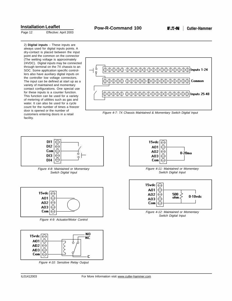
2) Digital inputs – These inputs arealways used for digital inputs points. Adry-contact is placed between the inputpoint and the common on the connector(The wetting voltage is approximately24VDC). Digital inputs may be connectedthrough terminal on the 7X chassis to anSOC. Some application specific control-lers also have auxiliary digital inputs onthe controller low voltage connectors.The input can be defined at start up as avariety of maintained and momentarycontact configurations. One special usefor these inputs is a counter function.This function can be used for a varietyof metering of utilities such as gas andwater. It can also be used for a cyclecount for the number of times a freezerdoor is opened or the number ofcustomers entering doors in a retailfacility.
Figure 4-7: 7X Chassis Maintained & Momentary Switch Digital Input
Figure 4-8: Maintained or MomentarySwitch Digital Input
Figure 4-11: Maintained or MomentarySwitch Digital Input
Figure 4-9: Actuator/Motor Control
Figure 4-10: Sensitive Relay Output
Figure 4-12: Maintained or MomentarySwitch Digital Input
Installation LeafletPage 13 Effective: April 2003
Pow-R-Command 100
IL01412003 For More Information visit www.cutler-hammer.com
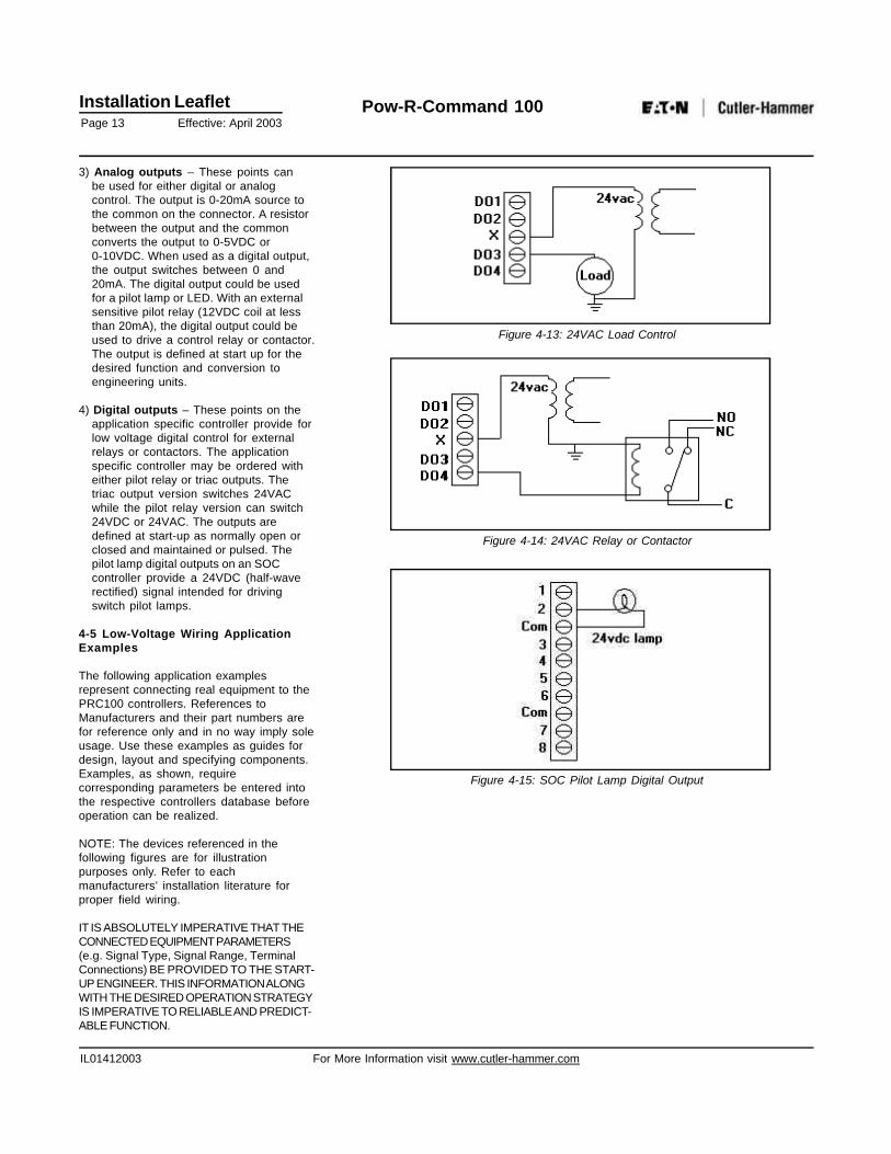
3) Analog outputs – These points canbe used for either digital or analogcontrol. The output is 0-20mA source tothe common on the connector. A resistorbetween the output and the commonconverts the output to 0-5VDC or0-10VDC. When used as a digital output,the output switches between 0 and20mA. The digital output could be usedfor a pilot lamp or LED. With an externalsensitive pilot relay (12VDC coil at lessthan 20mA), the digital output could beused to drive a control relay or contactor.The output is defined at start up for thedesired function and conversion toengineering units.
4) Digital outputs – These points on theapplication specific controller provide forlow voltage digital control for externalrelays or contactors. The applicationspecific controller may be ordered witheither pilot relay or triac outputs. Thetriac output version switches 24VACwhile the pilot relay version can switch24VDC or 24VAC. The outputs aredefined at start-up as normally open orclosed and maintained or pulsed. Thepilot lamp digital outputs on an SOCcontroller provide a 24VDC (half-waverectified) signal intended for drivingswitch pilot lamps.
4-5 Low-Voltage Wiring ApplicationExamples
The following application examplesrepresent connecting real equipment to thePRC100 controllers. References toManufacturers and their part numbers arefor reference only and in no way imply soleusage. Use these examples as guides fordesign, layout and specifying components.Examples, as shown, requirecorresponding parameters be entered intothe respective controllers database beforeoperation can be realized.
NOTE: The devices referenced in thefollowing figures are for illustrationpurposes only. Refer to eachmanufacturers’ installation literature forproper field wiring.
IT IS ABSOLUTELY IMPERATIVE THAT THECONNECTED EQUIPMENT PARAMETERS(e.g. Signal Type, Signal Range, TerminalConnections) BE PROVIDED TO THE START-UP ENGINEER. THIS INFORMATION ALONGWITH THE DESIRED OPERATION STRATEGYIS IMPERATIVE TO RELIABLE AND PREDICT-ABLE FUNCTION.
Figure 4-15: SOC Pilot Lamp Digital Output
Figure 4-14: 24VAC Relay or Contactor
Figure 4-13: 24VAC Load Control
Installation LeafletPage 14 Effective: April 2003
Pow-R-Command 100
IL01412003 For More Information visit www.cutler-hammer.com
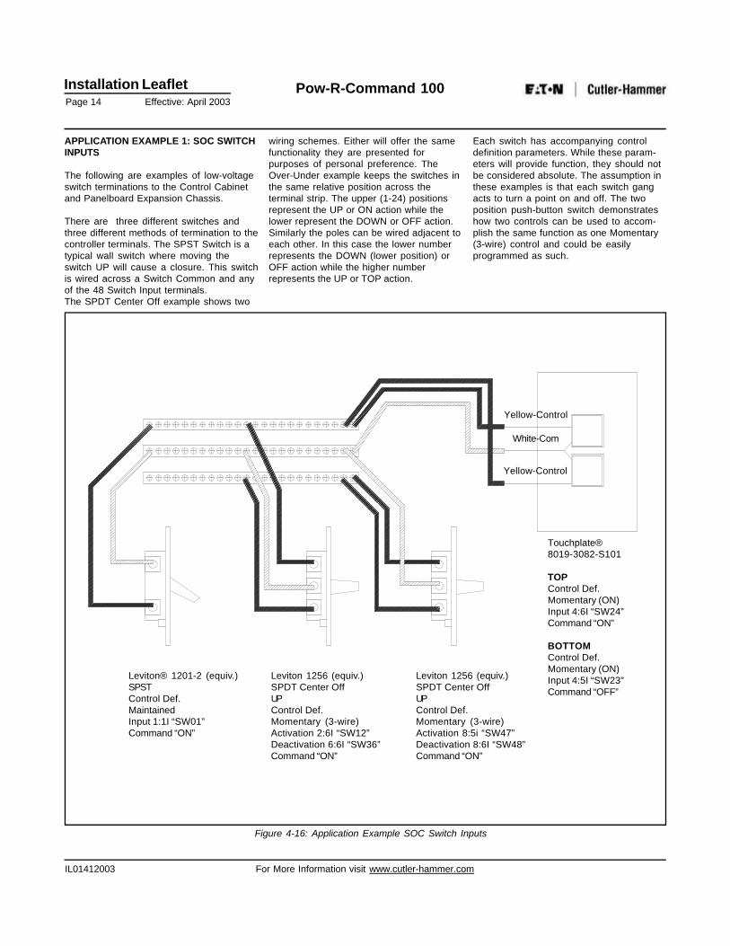
APPLICATION EXAMPLE 1: SOC SWITCHINPUTS
The following are examples of low-voltageswitch terminations to the Control Cabinetand Panelboard Expansion Chassis.
There are three different switches andthree different methods of termination to thecontroller terminals. The SPST Switch is atypical wall switch where moving theswitch UP will cause a closure. This switchis wired across a Switch Common and anyof the 48 Switch Input terminals.The SPDT Center Off example shows two
wiring schemes. Either will offer the samefunctionality they are presented forpurposes of personal preference. TheOver-Under example keeps the switches inthe same relative position across theterminal strip. The upper (1-24) positionsrepresent the UP or ON action while thelower represent the DOWN or OFF action.Similarly the poles can be wired adjacent toeach other. In this case the lower numberrepresents the DOWN (lower position) orOFF action while the higher numberrepresents the UP or TOP action.
Figure 4-16: Application Example SOC Switch Inputs
Each switch has accompanying controldefinition parameters. While these param-eters will provide function, they should notbe considered absolute. The assumption inthese examples is that each switch gangacts to turn a point on and off. The twoposition push-button switch demonstrateshow two controls can be used to accom-plish the same function as one Momentary(3-wire) control and could be easilyprogrammed as such.
Leviton® 1201-2 (equiv.)SPSTControl Def.MaintainedInput 1:1I “SW01”Command “ON”
Leviton 1256 (equiv.)SPDT Center OffUPControl Def.Momentary (3-wire)Activation 2:6I “SW12”Deactivation 6:6I “SW36”Command “ON”
Leviton 1256 (equiv.)SPDT Center OffUPControl Def.Momentary (3-wire)Activation 8:5i “SW47”Deactivation 8:6I “SW48”Command “ON”
Touchplate®8019-3082-S101
TOPControl Def.Momentary (ON)Input 4:6I “SW24”Command “ON”
BOTTOMControl Def.Momentary (ON)Input 4:5I “SW23”Command “OFF”
Yellow-Control
White-Com
Yellow-Control
Installation LeafletPage 15 Effective: April 2003
Pow-R-Command 100
IL01412003 For More Information visit www.cutler-hammer.com
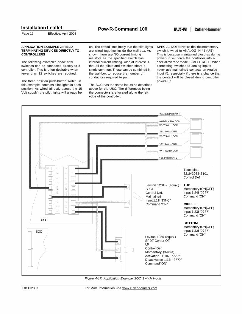
APPLICATION EXAMPLE 2: FIELDTERMINATING DEVICES DIRECTLY TOCONTROLLERS
The following examples show howswitches can be connected directly to acontroller. This is often desirable whenfewer than 12 switches are required.
The three position push-button switch, inthis example, contains pilot lights in eachposition. As wired (directly across the 15Volt supply) the pilot lights will always be
Figure 4-17: Application Example SOC Switch Inputs
on. The dotted lines imply that the pilot lightsare wired together inside the wall-box. Asshown there are NO current limitingresistors as the specified switch hasinternal current limiting. Also of interest isthat all the pilots and switches share asingle common. These can be combined inthe wall-box to reduce the number ofconductors required to pull.
The SOC has the same inputs as describedabove for the USC. The differences beingthe connectors are located along the leftedge of the controller.
SPECIAL NOTE: Notice that the momentaryswitch is wired to ANALOG IN #1 (UI1).This is because maintained closures duringpower-up will force the controller into aspecial override mode. SIMPLE RULE: Whenconnecting switches to analog inputs –never use maintained contacts on AnalogInput #1, especially if there is a chance thatthe contact will be closed during controllerpower-up.
Leviton 1201-2 (equiv.)SPSTControl Def.MaintainedInput 1:11I “DINC”Command “ON”
Leviton 1256 (equiv.)SPDT Center OffUPControl DefMomentary (3-wire)Activation 1:187I “????”Deactivation 1:17I “????”Command “ON”
Touchplate8219-3083-S101Control Def
TOPMomentary (ON|OFF)Input 1:24I “????”Command “ON”
MIDDLEMomentary (ON|OFF)Input 1:23I “????”Command “ON”
BOTTOMMomentary (ON|OFF)Input 1:22I “????”Command “ON”
SOC
USC
YEL/BLK Pilot PWR
WHT/BLK Pilot COM
WHT Switch COM
YEL Switch CNTL
WHT Switch COM
YEL Switch CNTL
WHT Switch COM
YEL Switch CNTL
Installation LeafletPage 16 Effective: April 2003
Pow-R-Command 100
IL01412003 For More Information visit www.cutler-hammer.com
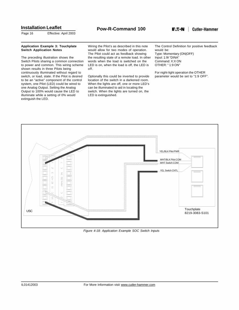
Application Example 3: TouchplateSwitch Application Notes
The preceding illustration shows theSwitch Pilots sharing a common connectionto power and common. This wiring schemeshown results in three Pilots beingcontinuously illuminated without regard toswitch, or load, state. If the Pilot is desiredto be an “active” component of the controlsystem, one Pilot (LED) could be wired toone Analog Output. Setting the AnalogOutput to 100% would cause the LED toilluminate while a setting of 0% wouldextinguish the LED.
Wiring the Pilot’s as described in this notewould allow for two modes of operation.The Pilot could act as feedback showingthe resulting state of a remote load. In otherwords when the load is switched on theLED is on, when the load is off, the LED isoff.
Optionally this could be inverted to providelocation of the switch in a darkened room.When the lights are off, one or more LED’scan be illuminated to aid in locating theswitch. When the lights are turned on, theLED is extinguished.
The Control Definition for positive feedbackwould be:Type: Momentary (ON|OFF)Input: 1:9I “DINA”Command: X:X ONOTHER: “ 1:9 ON”
For night-light operation the OTHERparameter would be set to “1:9 OFF”.
Figure 4-18: Application Example SOC Switch Inputs
Touchplate8219-3083-S101
YEL/BLK Pilot PWR
WHT/BLK Pilot COMWHT Switch COM
YEL Switch CNTL
USC
Installation LeafletPage 17 Effective: April 2003
Pow-R-Command 100
IL01412003 For More Information visit www.cutler-hammer.com
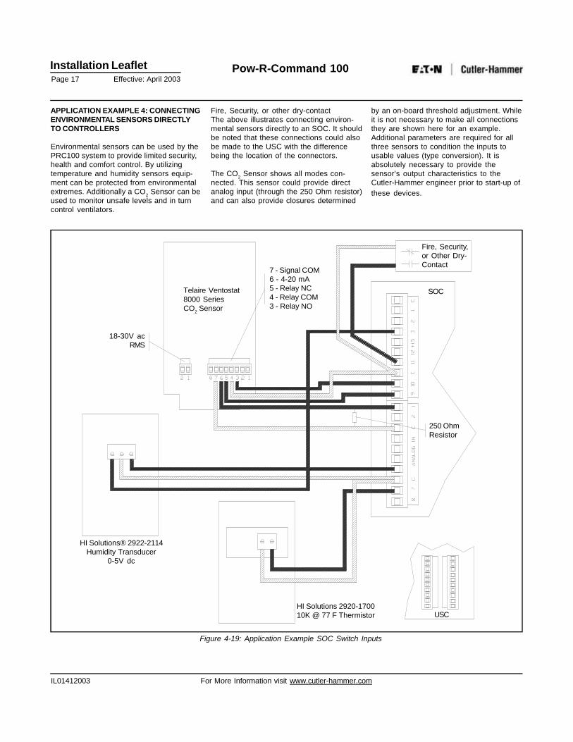
APPLICATION EXAMPLE 4: CONNECTINGENVIRONMENTAL SENSORS DIRECTLYTO CONTROLLERS
Environmental sensors can be used by thePRC100 system to provide limited security,health and comfort control. By utilizingtemperature and humidity sensors equip-ment can be protected from environmentalextremes. Additionally a CO2 Sensor can beused to monitor unsafe levels and in turncontrol ventilators.
Fire, Security, or other dry-contactThe above illustrates connecting environ-mental sensors directly to an SOC. It shouldbe noted that these connections could alsobe made to the USC with the differencebeing the location of the connectors.
The CO2 Sensor shows all modes con-nected. This sensor could provide directanalog input (through the 250 Ohm resistor)and can also provide closures determined
by an on-board threshold adjustment. Whileit is not necessary to make all connectionsthey are shown here for an example.Additional parameters are required for allthree sensors to condition the inputs tousable values (type conversion). It isabsolutely necessary to provide thesensor’s output characteristics to theCutler-Hammer engineer prior to start-up ofthese devices.
Figure 4-19: Application Example SOC Switch Inputs
18-30V acRMS
7 - Signal COM6 - 4-20 mA5 - Relay NC4 - Relay COM3 - Relay NO
Telaire Ventostat8000 SeriesCO2 Sensor
HI Solutions® 2922-2114Humidity Transducer
0-5V dc
HI Solutions 2920-170010K @ 77 F Thermistor USC
SOC
250 OhmResistor
Fire, Security,or Other Dry-Contact
Installation LeafletPage 18 Effective: April 2003
Pow-R-Command 100
IL01412003 For More Information visit www.cutler-hammer.com
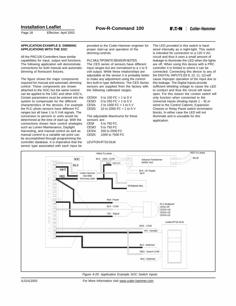
APPLICATION EXAMPLE 5: DIMMINGAPPLICATIONS WITH THE SOC
All the PRC100 Controllers have similarcapabilities for input, output and functions.The following application will demonstrateconnections for both manual and automaticdimming of florescent fixtures.
The figure shows the major componentsrequired for manual and automatic dimmingcontrol. These components are shownattached to the SOC but the same controlcan be applied to the USC and other ASC’s.Certain parameters must be entered into thesystem to compensate for the differentcharacteristics of the devices. For examplethe PLC photo sensors have different FCranges but all have 1 to 5 Volt signals. Theconversion to percent or units would bedetermined at the time of start-up. With theconnections shown here control strategiessuch as Lumen Maintenance, DaylightHarvesting, and manual control as well asmanual control to a variable set point canbe accomplished through programming thecontroller database. It is imperative that thesensor type associated with each input be
provided to the Cutler-Hammer engineer forproper start-up and operation of thedimming controls.
PLC MULTIPOINT® SENSOR NOTES.The CES series of sensors have differentinput ranges but are normalized to a 1 to 5volt output. While these relationships areadjustable at the sensor it is probably betterto make any adjustment using the control-lers built-in type definitions. The CES Seriessensors are supplied from the factory withthe following calibrated ranges.
CES®/I 0 to 100 FC = 1 to 5 VCES/O 0 to 250 FC = 1 to 5 VCES/A 2 to 1000 FC = 1 to 5 VCES/S 10 to 2000 FC = 1 to 5 V
The adjustable Maximums for thesesensors are:CES/I 5 to 750 FCCES/O 5 to 750 FCCES/A 200 to 2500 FCCES/S 1000 to 7500 FC
LEVITON IP710-DLW
The LED provided in this switch is hard-wired internally as a night-light. This switchis intended for connection to a 120 V ACcircuit and thus it uses a small amount ofleakage to illuminate the LED when the lightsare off. When using this device with a PRCcontroller it is limited to where it can beconnected. Connecting this device to any ofthe DIGITAL INPUTS (DI 9, 10, 11, 12) willcause improper operation of the input due tothis leakage. The Digital Inputs providesufficient whetting voltage to cause the LEDto conduct and thus the circuit will neveropen. For this reason the Leviton switch willonly function when connected to theUniversal Inputs (Analog Inputs 1 – 8) orwired to the Control Cabinet, ExpansionChassis or Relay Panel switch terminationblocks. In either case the LED will notilluminate and is unusable for thisapplication.
Figure 4-20: Application Example SOC Switch Inputs
SOC
BLK
RED
WHTCutler-Hammer
016-4092Dimming Cable
Yellow To Lamps
Red VIO-CV
BLK GRA - COM
40 Ballasts Max
Red - Power
BLK - COM
YEL - Signal
BLK - AC SupplyWHT
Advance TransformerMARK VII®
RED To Lamps
BLUE
PLC MultipointCES/I-1/5CES/O-1/5CES/A-1/5CES/S-1/5
GRA - COM
VIO - Variable
BLK - Switched
RED - Switch COM
BLK - Switched
Leviton IP710 -DLW
Installation LeafletPage 19 Effective: April 2003
Pow-R-Command 100
IL01412003 For More Information visit www.cutler-hammer.com
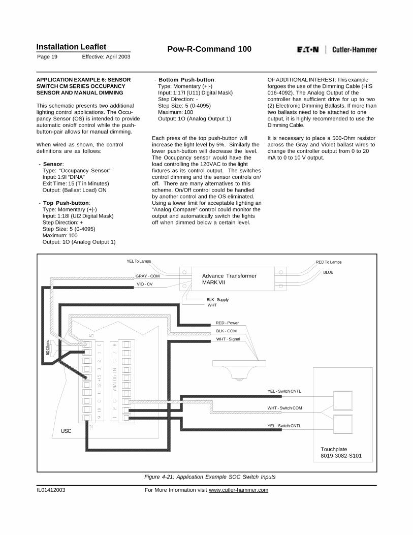
APPLICATION EXAMPLE 6: SENSORSWITCH CM SERIES OCCUPANCYSENSOR AND MANUAL DIMMING
This schematic presents two additionallighting control applications. The Occu-pancy Sensor (OS) is intended to provideautomatic on/off control while the push-button-pair allows for manual dimming.
When wired as shown, the controldefinitions are as follows:
- Sensor:Type: “Occupancy Sensor”Input: 1:9I “DINA”Exit Time: 15 (T in Minutes)Output: (Ballast Load) ON
- Top Push-button:Type: Momentary (+|-)Input: 1:18I (UI2 Digital Mask)Step Direction: +Step Size: 5 (0-4095)Maximum: 100Output: 1O (Analog Output 1)
- Bottom Push-button:Type: Momentary (+|-)Input: 1:17I (U11) Digital Mask)Step Direction: -Step Size: 5 (0-4095)Maximum: 100Output: 1O (Analog Output 1)
Each press of the top push-button willincrease the light level by 5%. Similarly thelower push-button will decrease the level.The Occupancy sensor would have theload controlling the 120VAC to the lightfixtures as its control output. The switchescontrol dimming and the sensor controls on/off. There are many alternatives to thisscheme. On/Off control could be handledby another control and the OS eliminated.Using a lower limit for acceptable lighting an“Analog Compare” control could monitor theoutput and automatically switch the lightsoff when dimmed below a certain level.
OF ADDITIONAL INTEREST: This exampleforgoes the use of the Dimming Cable (HIS016-4092). The Analog Output of thecontroller has sufficient drive for up to two(2) Electronic Dimming Ballasts. If more thantwo ballasts need to be attached to oneoutput, it is highly recommended to use theDimming Cable.
It is necessary to place a 500-Ohm resistoracross the Gray and Violet ballast wires tochange the controller output from 0 to 20mA to 0 to 10 V output.
Figure 4-21: Application Example SOC Switch Inputs
USC
50 O
hms
GRAY - COM
VIO - CV
YEL To Lamps RED To Lamps
BLUE
BLK - SupplyWHT
RED - Power
BLK - COM
YEL - Switch CNTL
WHT - Switch COM
YEL - Switch CNTL
Advance TransformerMARK VII
Touchplate8019-3082-S101
WHT - Signal
Installation LeafletPage 20 Effective: April 2003
Pow-R-Command 100
IL01412003 For More Information visit www.cutler-hammer.com
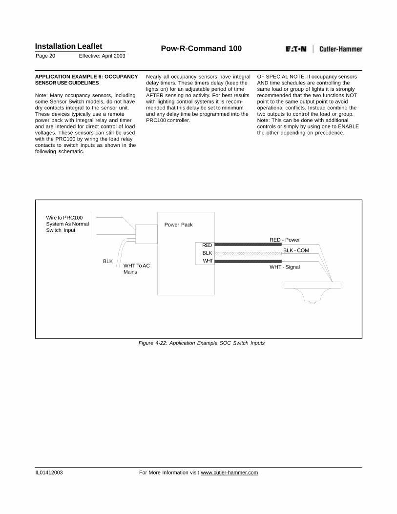
APPLICATION EXAMPLE 6: OCCUPANCYSENSOR USE GUIDELINES
Note: Many occupancy sensors, includingsome Sensor Switch models, do not havedry contacts integral to the sensor unit.These devices typically use a remotepower pack with integral relay and timerand are intended for direct control of loadvoltages. These sensors can still be usedwith the PRC100 by wiring the load relaycontacts to switch inputs as shown in thefollowing schematic.
Nearly all occupancy sensors have integraldelay timers. These timers delay (keep thelights on) for an adjustable period of timeAFTER sensing no activity. For best resultswith lighting control systems it is recom-mended that this delay be set to minimumand any delay time be programmed into thePRC100 controller.
OF SPECIAL NOTE: If occupancy sensorsAND time schedules are controlling thesame load or group of lights it is stronglyrecommended that the two functions NOTpoint to the same output point to avoidoperational conflicts. Instead combine thetwo outputs to control the load or group.Note: This can be done with additionalcontrols or simply by using one to ENABLEthe other depending on precedence.
Figure 4-22: Application Example SOC Switch Inputs
Wire to PRC100System As NormalSwitch Input
BLKWHT To ACMains
Power Pack
REDBLKWHT
RED - Power
BLK - COM
WHT - Signal
Installation LeafletPage 21 Effective: April 2003
Pow-R-Command 100
IL01412003 For More Information visit www.cutler-hammer.com
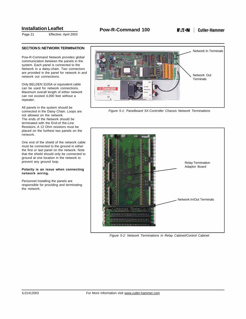
SECTION 5: NETWORK TERMINATION
Pow-R-Command Network provides globalcommunication between the panels in thesystem. Each panel is connected to theNetwork in a daisy-chain. Two connectorsare provided in the panel for network in andnetwork out connections.
Only BELDEN 3105A or equivalent cablecan be used for network connections.Maximum overall length of either networkcan not exceed 4,000 feet without arepeater.
All panels in the system should beconnected in the Daisy Chain. Loops arenot allowed on the network.The ends of the Network should beterminated with the End-of the-LineResistors. A 12 Ohm resistors must beplaced on the furthest two panels on thenetwork.
One end of the shield of the network cablemust be connected to the ground in eitherthe first or last panel on the network. Notethat the shield should only be connected toground at one location in the network toprevent any ground loop.
Polarity is an issue when connectingnetwork wiring.
Personnel installing the panels areresponsible for providing and terminatingthe network.
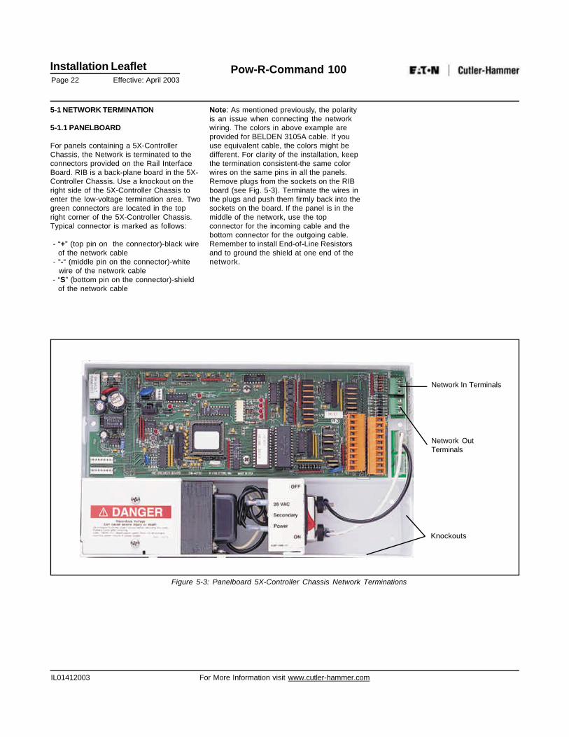
Network In/Out Terminals
Relay TerminationAdaptor Board
Figure 5-2: Network Terminations In Relay Cabinet/Control Cabinet
Network In Terminals
Network OutTerminals
Figure 5-1: Panelboard 5X-Controller Chassis Network Terminations
Installation LeafletPage 22 Effective: April 2003
Pow-R-Command 100
IL01412003 For More Information visit www.cutler-hammer.com
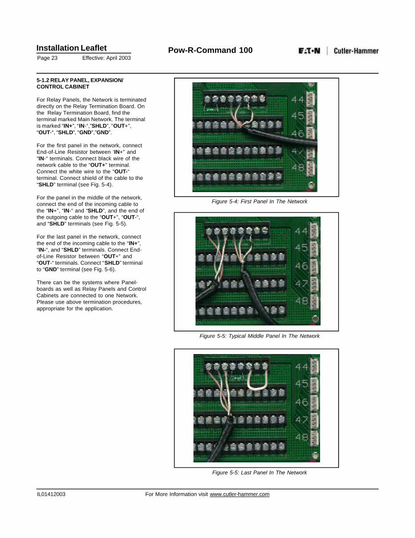
5-1 NETWORK TERMINATION
5-1.1 PANELBOARD
For panels containing a 5X-ControllerChassis, the Network is terminated to theconnectors provided on the Rail InterfaceBoard. RIB is a back-plane board in the 5X-Controller Chassis. Use a knockout on theright side of the 5X-Controller Chassis toenter the low-voltage termination area. Twogreen connectors are located in the topright corner of the 5X-Controller Chassis.Typical connector is marked as follows:
- “+” (top pin on the connector)-black wire of the network cable - “-“ (middle pin on the connector)-white wire of the network cable - “S” (bottom pin on the connector)-shield of the network cable
Network In Terminals
Network OutTerminals
Figure 5-3: Panelboard 5X-Controller Chassis Network Terminations
Knockouts
Note: As mentioned previously, the polarityis an issue when connecting the networkwiring. The colors in above example areprovided for BELDEN 3105A cable. If youuse equivalent cable, the colors might bedifferent. For clarity of the installation, keepthe termination consistent-the same colorwires on the same pins in all the panels.Remove plugs from the sockets on the RIBboard (see Fig. 5-3). Terminate the wires inthe plugs and push them firmly back into thesockets on the board. If the panel is in themiddle of the network, use the topconnector for the incoming cable and thebottom connector for the outgoing cable.Remember to install End-of-Line Resistorsand to ground the shield at one end of thenetwork.
Installation LeafletPage 23 Effective: April 2003
Pow-R-Command 100
IL01412003 For More Information visit www.cutler-hammer.com
5-1.2 RELAY PANEL, EXPANSION/CONTROL CABINET
For Relay Panels, the Network is terminateddirectly on the Relay Termination Board. Onthe Relay Termination Board, find theterminal marked Main Network. The terminalis marked “IN+”, “IN-“,”SHLD”, “OUT+”,“OUT-“, “SHLD”, “GND”,”GND”.
For the first panel in the network, connectEnd-of-Line Resistor between ‘IN+” and“IN-“ terminals. Connect black wire of thenetwork cable to the “OUT+” terminal.Connect the white wire to the “OUT-“terminal. Connect shield of the cable to the“SHLD” terminal (see Fig. 5-4).
For the panel in the middle of the network,connect the end of the incoming cable tothe “IN+”, “IN-“ and “SHLD”, and the end ofthe outgoing cable to the “OUT+”, “OUT-“,and “SHLD” terminals (see Fig. 5-5).
For the last panel in the network, connectthe end of the incoming cable to the “IN+”,“IN-“, and “SHLD” terminals. Connect End-of-Line Resistor between “OUT+” and“OUT-“ terminals. Connect “SHLD” terminalto “GND” terminal (see Fig. 5-6).
There can be the systems where Panel-boards as well as Relay Panels and ControlCabinets are connected to one Network.Please use above termination procedures,appropriate for the application.
Figure 5-5: Typical Middle Panel In The Network
Figure 5-5: Last Panel In The Network
Figure 5-4: First Panel In The Network
Installation LeafletPage 24 Effective: April 2003
Pow-R-Command 100
IL01412003 For More Information visit www.cutler-hammer.com
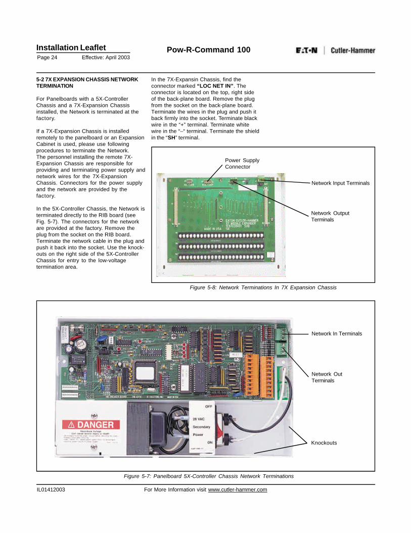
5-2 7X EXPANSION CHASSIS NETWORKTERMINATION
For Panelboards with a 5X-ControllerChassis and a 7X-Expansion Chassisinstalled, the Network is terminated at thefactory.
If a 7X-Expansion Chassis is installedremotely to the panelboard or an ExpansionCabinet is used, please use followingprocedures to terminate the Network.The personnel installing the remote 7X-Expansion Chassis are responsible forproviding and terminating power supply andnetwork wires for the 7X-ExpansionChassis. Connectors for the power supplyand the network are provided by thefactory.
In the 5X-Controller Chassis, the Network isterminated directly to the RIB board (seeFig. 5-7). The connectors for the networkare provided at the factory. Remove theplug from the socket on the RIB board.Terminate the network cable in the plug andpush it back into the socket. Use the knock-outs on the right side of the 5X-ControllerChassis for entry to the low-voltagetermination area.
Network In Terminals
Network OutTerminals
Figure 5-7: Panelboard 5X-Controller Chassis Network Terminations
Knockouts
In the 7X-Expansin Chassis, find theconnector marked “LOC NET IN”. Theconnector is located on the top, right sideof the back-plane board. Remove the plugfrom the socket on the back-plane board.Terminate the wires in the plug and push itback firmly into the socket. Terminate blackwire in the “+” terminal. Terminate whitewire in the “–“ terminal. Terminate the shieldin the “SH” terminal.
Power SupplyConnector
Network Input Terminals
Network OutputTerminals
Figure 5-8: Network Terminations In 7X Expansion Chassis
Installation LeafletPage 25 Effective: April 2003
Pow-R-Command 100
IL01412003 For More Information visit www.cutler-hammer.com
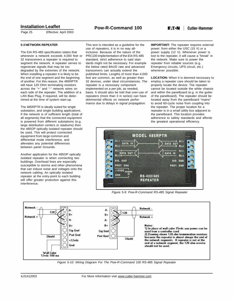
5-3 NETWORK REPEATER
The EIA RS-485 specification states thatwhenever a network exceeds 4,000 feet or32 transceivers a repeater is required tosegment the network. A repeater serves toregenerate signals that may be toodegraded by the extremes of the network.When installing a repeater it is likely to bethe end of one segment and the beginningof another. For this reason, the 485RPTRwill have 120 Ohm terminating resistorsacross the “+” and “-“ network wires oneach side of the repeater. The addition of aLAN Bias Plug, if required, will be deter-mined at the time of system start-up.
The 485RPTR is ideally suited for singlesubstation, and single building applications.If the network is of sufficient length (total ofall segments) that the connected equipmentis powered from different substations (e.g.large distribution centers or stadiums) thenthe 485OP optically isolated repeater shouldbe used. This will protect connectedequipment from large common anddifferential mode interference, andalleviates any potential differencesbetween panel Grounds.
Another application for the 485OP opticallyisolated repeater is when connecting twobuildings. Overhead lines are especiallysusceptible to storms and other phenomenathat can induce noise and voltages onto thenetwork cabling. An optically isolatedrepeater at the entry-point to each buildingwill offer greater protection against thisinterference.
This text is intended as a guideline for theuse of repeaters, it is in no way all-inclusive. Because of the nature of thePRC100 implementation of the EIA RS-485standard, strict adherence to said stan-dards might not be necessary. For examplethe below rated BAUD rate and advancedtransceivers can actually extend thepublished limits. Lengths of more than 4,000feet are common, as well as greater than32 devices, under ideal circumstances. Therepeater is a necessary componentimplemented on a per-job, as needed,basis. It should also be told that over-use ofrepeaters (more than 3 in series) can havedetrimental effects on network perfor-mance due to delays in signal propagation.
IMPORTANT: The repeater requires externalpower; from either the USC (15 V) or apower supply (12 V). Whenever power islost to the repeater, it will cause a “break” inthe network. Make sure to power therepeater from reliable sources (e.g.Emergency circuits, UPS circuit, etc.)whenever possible.
LOCATION: When it is deemed necessary toemploy a repeater care should be taken toproperly locate the device. The repeatercannot be located outside the white chassisand within the panelboard (e.g. in the gutterof the panelboard). The repeater should belocated away from the panelboard “mains”to avoid 60-cycle noise from coupling intothe repeater. The proper location for arepeater is in a small utility box adjacent tothe panelboard. This location providesadherence to safety standards and affordsthe greatest operational efficiency.
Figure 5-9: Pow-R-Command RS-485 Signal Repeater
Figure 5-10: Wiring Diagram For The Pow-R-Command 100 RS-485 Signal Repeater
Installation LeafletPage 26 Effective: April 2003
Pow-R-Command 100
IL01412003 For More Information visit www.cutler-hammer.com
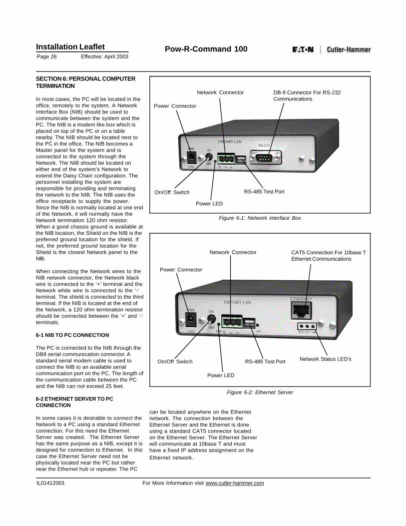
SECTION 6: PERSONAL COMPUTERTERMINATION
In most cases, the PC will be located in theoffice, remotely to the system. A NetworkInterface Box (NIB) should be used tocommunicate between the system and thePC. The NIB is a modem like box which isplaced on top of the PC or on a tablenearby. The NIB should be located next tothe PC in the office. The NIB becomes aMaster panel for the system and isconnected to the system through theNetwork. The NIB should be located oneither end of the system’s Network toextend the Daisy Chain configuration. Thepersonnel installing the system areresponsible for providing and terminatingthe network to the NIB. The NIB uses theoffice receptacle to supply the power.Since the NIB is normally located at one endof the Network, it will normally have theNetwork termination 120 ohm resistor.When a good chassis ground is available atthe NIB location, the Shield on the NIB is thepreferred ground location for the shield. Ifnot, the preferred ground location for theShield is the closest Network panel to theNIB.
When connecting the Network wires to theNIB network connector, the Network blackwire is connected to the ‘+’ terminal and theNetwork white wire is connected to the ‘-‘terminal. The shield is connected to the thirdterminal. If the NIB is located at the end ofthe Network, a 120 ohm termination resistorshould be connected between the ‘+’ and ‘-‘terminals.
6-1 NIB TO PC CONNECTION
The PC is connected to the NIB through theDB9 serial communication connector. Astandard serial modem cable is used toconnect the NIB to an available serialcommunication port on the PC. The length ofthe communication cable between the PCand the NIB can not exceed 25 feet.
6-2 ETHERNET SERVER TO PCCONNECTION
In some cases it is desirable to connect theNetwork to a PC using a standard Ethernetconnection. For this need the EthernetServer was created. The Ethernet Serverhas the same purpose as a NIB, except it isdesigned for connection to Ethernet. In thiscase the Ethernet Server need not bephysically located near the PC but rathernear the Ethernet hub or repeater. The PC
can be located anywhere on the Ethernetnetwork. The connection between theEthernet Server and the Ethernet is doneusing a standard CAT5 connector locatedon the Ethernet Server. The Ethernet Serverwill communicate at 10base T and musthave a fixed IP address assignment on theEthernet network.
Power Connector
On/Off Switch
Power LED
Network Connector
RS-485 Test Port
DB-9 Connector For RS-232Communications
Figure 6-1: Network interface Box
Power Connector
On/Off Switch
Power LED
RS-485 Test Port
Network Connector CAT5 Connection For 10base TEthernet Communications
Network Status LED’s
Figure 6-2: Ethernet Server
Installation LeafletPage 27 Effective: April 2003
Pow-R-Command 100
IL01412003 For More Information visit www.cutler-hammer.com
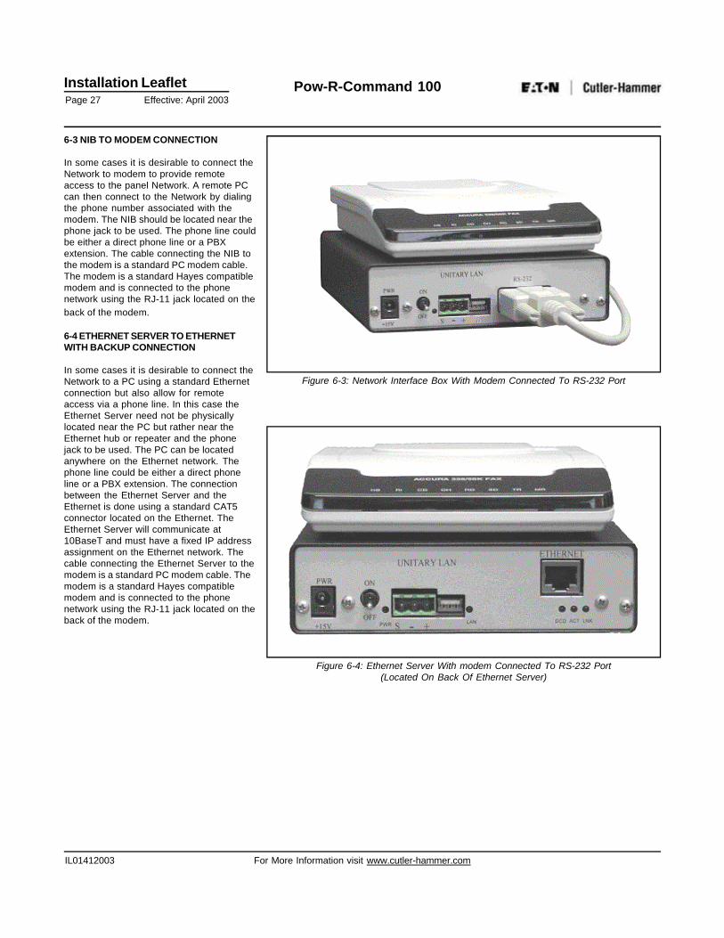
6-3 NIB TO MODEM CONNECTION
In some cases it is desirable to connect theNetwork to modem to provide remoteaccess to the panel Network. A remote PCcan then connect to the Network by dialingthe phone number associated with themodem. The NIB should be located near thephone jack to be used. The phone line couldbe either a direct phone line or a PBXextension. The cable connecting the NIB tothe modem is a standard PC modem cable.The modem is a standard Hayes compatiblemodem and is connected to the phonenetwork using the RJ-11 jack located on theback of the modem.
6-4 ETHERNET SERVER TO ETHERNETWITH BACKUP CONNECTION
In some cases it is desirable to connect theNetwork to a PC using a standard Ethernetconnection but also allow for remoteaccess via a phone line. In this case theEthernet Server need not be physicallylocated near the PC but rather near theEthernet hub or repeater and the phonejack to be used. The PC can be locatedanywhere on the Ethernet network. Thephone line could be either a direct phoneline or a PBX extension. The connectionbetween the Ethernet Server and theEthernet is done using a standard CAT5connector located on the Ethernet. TheEthernet Server will communicate at10BaseT and must have a fixed IP addressassignment on the Ethernet network. Thecable connecting the Ethernet Server to themodem is a standard PC modem cable. Themodem is a standard Hayes compatiblemodem and is connected to the phonenetwork using the RJ-11 jack located on theback of the modem.
Figure 6-3: Network Interface Box With Modem Connected To RS-232 Port
Figure 6-4: Ethernet Server With modem Connected To RS-232 Port(Located On Back Of Ethernet Server)
Installation LeafletPage 28 Effective: April 2003
Pow-R-Command 100
IL01412003 For More Information visit www.cutler-hammer.com
SECTION 7: CONTROLLERADDRESSING
Before multiple panels can interact amongthemselves and the Console, they must bephysically wired to the network asdescribed in Section 5. The following topicsdescribe the procedures available forassigning a unique network address toeach controller. With either of the followingprocedures remember optimum perfor-mance is attained when addresses areassigned contiguously from low to high (1to 120).
The following steps assume familiarity withthe Windows Operating System andgeneral computer skills. If you are unfamiliarwith such tasks as using the mouse orbasic file manipulation refer to the userdocumentation supplied with your computeror software.
7-1 ADDRESSING USING A PC
To use the Console (PC) as the point ofassignment it is first necessary to install thePow-R-Command 100 software onto thePC. Second the NIB or Ethernet Server mustbe connected between the PC and Networkper Section 6. The final step is to insurethat each device is programmed to a uniqueaddress so the computer (and operator)can determine which controller is beingqueried or programmed.
If the controllers are installed into theirrespective panels the following procedurewill require two people with remotecommunications. It is otherwise possible forone person to perform this by pre-addressing all cards at one panel. Thiswould require a temporary connection ofthe NIB to a panel and a PC connected tothe NIB. Each card is then “added” to thenetwork and removed from this panel andplaced in the appropriate panel.Alternatively a NIB can be used with aLaptop PC and a short network cable toconnect to each panel. This way theLaptop and NIB could be moved from panelto panel.
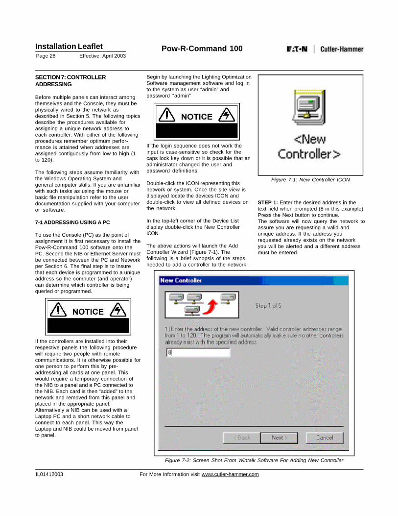
Begin by launching the Lighting OptimizationSoftware management software and log into the system as user “admin” andpassword “admin”
If the login sequence does not work theinput is case-sensitive so check for thecaps lock key down or it is possible that anadministrator changed the user andpassword definitions.
Double-click the ICON representing thisnetwork or system. Once the site view isdisplayed locate the devices ICON anddouble-click to view all defined devices onthe network.
In the top-left corner of the Device Listdisplay double-click the New ControllerICON.
The above actions will launch the AddController Wizard (Figure 7-1). Thefollowing is a brief synopsis of the stepsneeded to add a controller to the network.
Figure 7-1: New Controller ICON
STEP 1: Enter the desired address in thetext field when prompted (8 in this example).Press the Next button to continue.The software will now query the network toassure you are requesting a valid andunique address. If the address yourequested already exists on the networkyou will be alerted and a different addressmust be entered.
Figure 7-2: Screen Shot From Wintalk Software For Adding New Controller
Installation LeafletPage 29 Effective: April 2003
Pow-R-Command 100
IL01412003 For More Information visit www.cutler-hammer.com
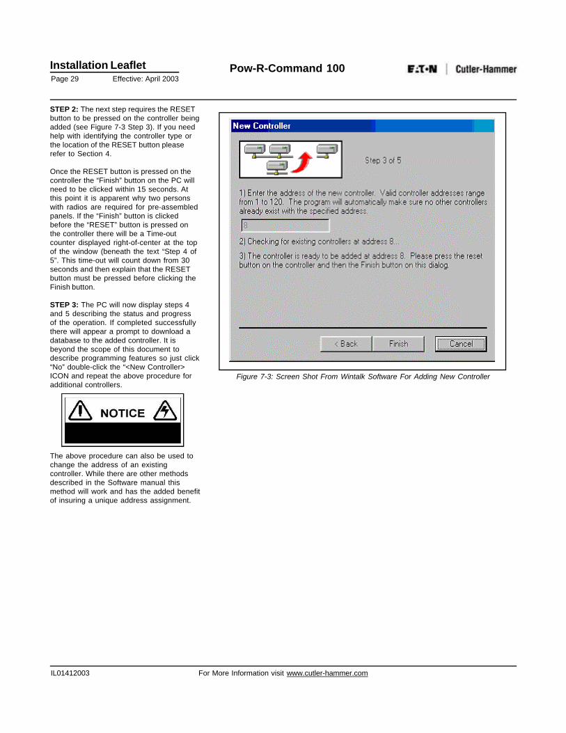
STEP 2: The next step requires the RESETbutton to be pressed on the controller beingadded (see Figure 7-3 Step 3). If you needhelp with identifying the controller type orthe location of the RESET button pleaserefer to Section 4.
Once the RESET button is pressed on thecontroller the “Finish” button on the PC willneed to be clicked within 15 seconds. Atthis point it is apparent why two personswith radios are required for pre-assembledpanels. If the “Finish” button is clickedbefore the “RESET” button is pressed onthe controller there will be a Time-outcounter displayed right-of-center at the topof the window (beneath the text “Step 4 of5”. This time-out will count down from 30seconds and then explain that the RESETbutton must be pressed before clicking theFinish button.
STEP 3: The PC will now display steps 4and 5 describing the status and progressof the operation. If completed successfullythere will appear a prompt to download adatabase to the added controller. It isbeyond the scope of this document todescribe programming features so just click“No” double-click the “<New Controller>ICON and repeat the above procedure foradditional controllers.
The above procedure can also be used tochange the address of an existingcontroller. While there are other methodsdescribed in the Software manual thismethod will work and has the added benefitof insuring a unique address assignment.
Figure 7-3: Screen Shot From Wintalk Software For Adding New Controller
Installation LeafletPage 30 Effective: April 2003
Pow-R-Command 100
IL01412003 For More Information visit www.cutler-hammer.com
7-2 ADDRESSING USING A POCKET PCTEST TOOL
The most convenient means of adding(addressing) controllers to a network iswith the Pocket PC Test Tool. This is a smallhand-held device with software duplicatingsome functionality of the ManagementSoftware. This device connects directly tothe 4-Pin Network Test Port on a controller.Refer to SECTION 4 to identify both thecontroller type and location of the NetworkTest Port. The size and connectivity of thisdevice preclude the need for a secondperson as with the PC procedure describedabove.
Adding a controller to the network with thePocket PC tool is slightly different from thePC version. The Pocket PC tool is used tofirst locate the controller needing anaddress. A connection is then establishedwith the controller and the address ismanually entered in the system table. Thefollowing steps briefly describe thisprocedure:
STEP 1: Connect the network test tool tothe four-pin test connector on the controller(or nearby networked controller).
STEP 2: Launch the Utalk application on thePocket PC.
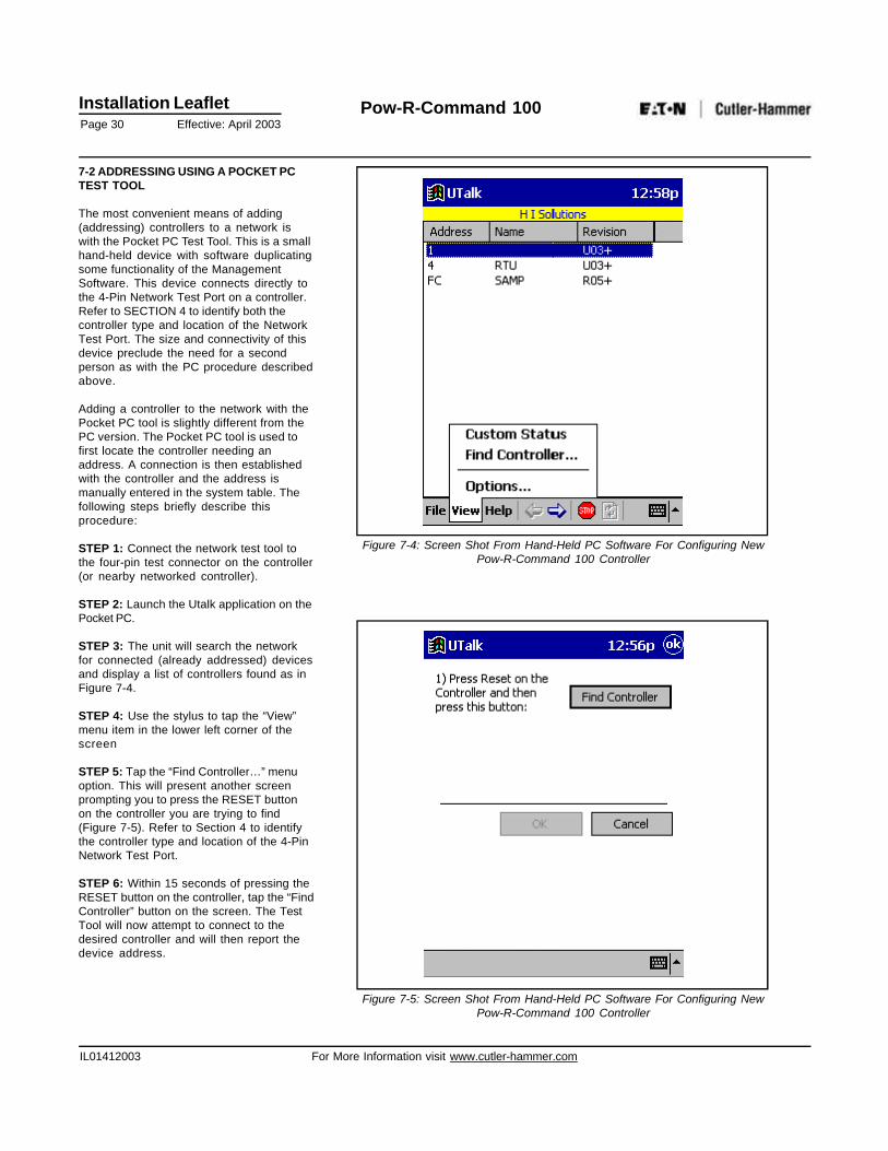
STEP 3: The unit will search the networkfor connected (already addressed) devicesand display a list of controllers found as inFigure 7-4.
STEP 4: Use the stylus to tap the “View”menu item in the lower left corner of thescreen
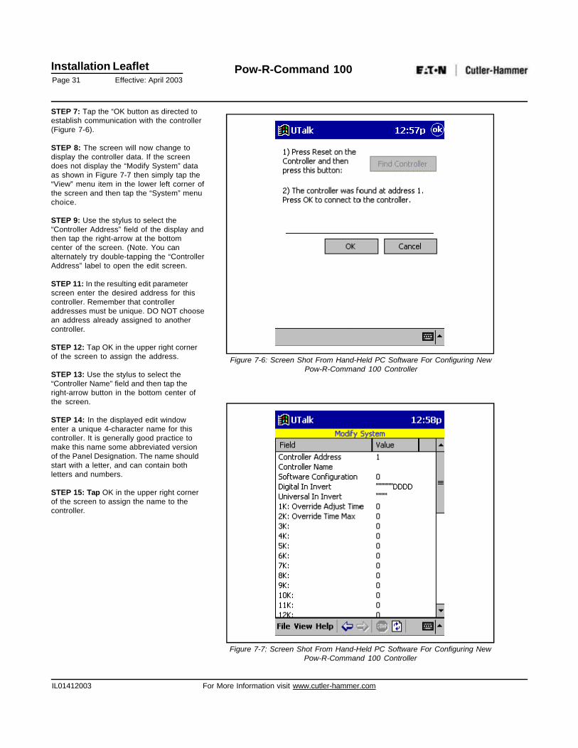
STEP 5: Tap the “Find Controller…” menuoption. This will present another screenprompting you to press the RESET buttonon the controller you are trying to find(Figure 7-5). Refer to Section 4 to identifythe controller type and location of the 4-PinNetwork Test Port.
STEP 6: Within 15 seconds of pressing theRESET button on the controller, tap the “FindController” button on the screen. The TestTool will now attempt to connect to thedesired controller and will then report thedevice address.
Figure 7-5: Screen Shot From Hand-Held PC Software For Configuring NewPow-R-Command 100 Controller
Figure 7-4: Screen Shot From Hand-Held PC Software For Configuring NewPow-R-Command 100 Controller
Installation LeafletPage 31 Effective: April 2003
Pow-R-Command 100
IL01412003 For More Information visit www.cutler-hammer.com
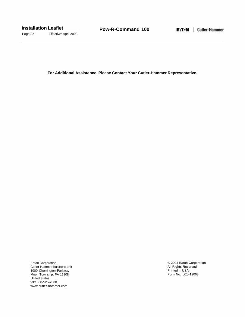
STEP 7: Tap the “OK button as directed toestablish communication with the controller(Figure 7-6).
STEP 8: The screen will now change todisplay the controller data. If the screendoes not display the “Modify System” dataas shown in Figure 7-7 then simply tap the“View” menu item in the lower left corner ofthe screen and then tap the “System” menuchoice.
STEP 9: Use the stylus to select the“Controller Address” field of the display andthen tap the right-arrow at the bottomcenter of the screen. (Note. You canalternately try double-tapping the “ControllerAddress” label to open the edit screen.
STEP 11: In the resulting edit parameterscreen enter the desired address for thiscontroller. Remember that controlleraddresses must be unique. DO NOT choosean address already assigned to anothercontroller.
STEP 12: Tap OK in the upper right cornerof the screen to assign the address.
STEP 13: Use the stylus to select the“Controller Name” field and then tap theright-arrow button in the bottom center ofthe screen.
STEP 14: In the displayed edit windowenter a unique 4-character name for thiscontroller. It is generally good practice tomake this name some abbreviated versionof the Panel Designation. The name shouldstart with a letter, and can contain bothletters and numbers.
STEP 15: Tap OK in the upper right cornerof the screen to assign the name to thecontroller.
Figure 7-6: Screen Shot From Hand-Held PC Software For Configuring NewPow-R-Command 100 Controller
Figure 7-7: Screen Shot From Hand-Held PC Software For Configuring NewPow-R-Command 100 Controller
Installation LeafletPage 32 Effective: April 2003
Pow-R-Command 100
For Additional Assistance, Please Contact Your Cutler-Hammer Representative.
Eaton CorporationCutler-Hammer business unit1000 Cherrington ParkwayMoon Township, PA 15108United Statestel:1800-525-2000www.cutler-hammer.com
© 2003 Eaton CorporationAll Rights ReservedPrinted In USAForm No. IL01412003