power and precision in perfect harmony - fuji …english).pdf · power and precision in perfect...
TRANSCRIPT

POWER AND PRECISION IN PERFECT HARMONY
J A P A N E S E Q U A L I T Y S I N C E 1 9 4 3
I N D U S T R I A L T O O L S

F U J I T O O L S
INDUSTRIAL TOOLS. JAPANESE QUALITY SINCE 1943
From the beginning, Fuji has manufactured tools for some of the toughest and most demanding industrial environments in Japan and on the planet. This has resulted in a wide
range of robust and long lasting material removal tools that is the preferred choice for metalworking in Japan and many places overseas. Our range of assembly tools and error proofing solutions was born from the needs of the Japanese manufacturing industry and delivers quality and safety together with speed of operation and ergonomic handling.
Every Fuji tool, from the simplest to the most sophisticated, is built to the same exacting standards. “Monozukuri”, Japanese craftsmanship,
is a core value in both manufacturing and design. Over 60 years of non-stop investment in R&D and kaizen manufacturing ensures that our products are built using proven, advanced technologies and provide superior ergonomics, safety and handling. Moreover, our commitment extends beyond our products to include the world we live in. Our production facilities are compliant with both the ISO 9001 and ISO 14001 standards.
A DEEP JAPANESE HERITAGE
COMMITMENT TO QUALITY AND TECHNOLOGY
Power and Prec is io n in Perfect harmony

F U J I T O O L S - N E E D T O K N O W M O R E ? : W W W . F U J I T O O L S . C O M 1
With a catalogue of over 1,400 references, we have one of the most extensive, most cost effective ranges of industrial tools available today. Our engineering team also has a long history of collaborating with customers to design solutions for special needs, both large and small.
Fuji Tools are available through our network of authorized distributors that provide highly reactive after-sales service. They ensure that after years of service our products perform just as well as on day one. We support this network through both a dedicated international team in Japan and local market representatives in over 20 countries.
WIDE RANGE OF STANDARD AND SPECIAL PRODUCT
COMMITTED TO LONG TERM CUSTOMER SATISFACTION
Need to know more?
> www.fujitools.com
OUR COMPANY IS CERTIFIED ISO 9001
QUALITY MANAGEMENT AND ISO 14001
ENVIRONMENTAL MANAGEMENT STANDARDS.
Q U A L I T Y GUARANTEED
F U J I T O O L S - N E E D T O K N O W M O R E ? : W W W . F U J I T O O L S . C O M2
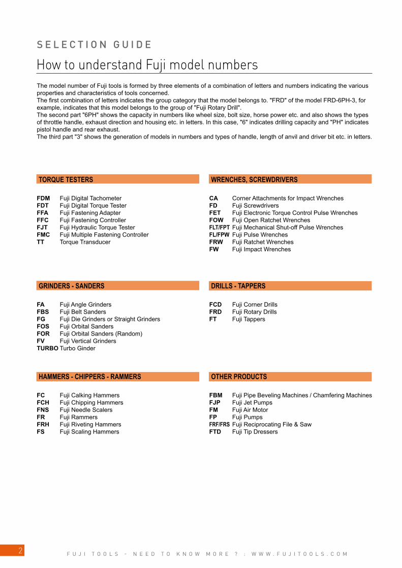
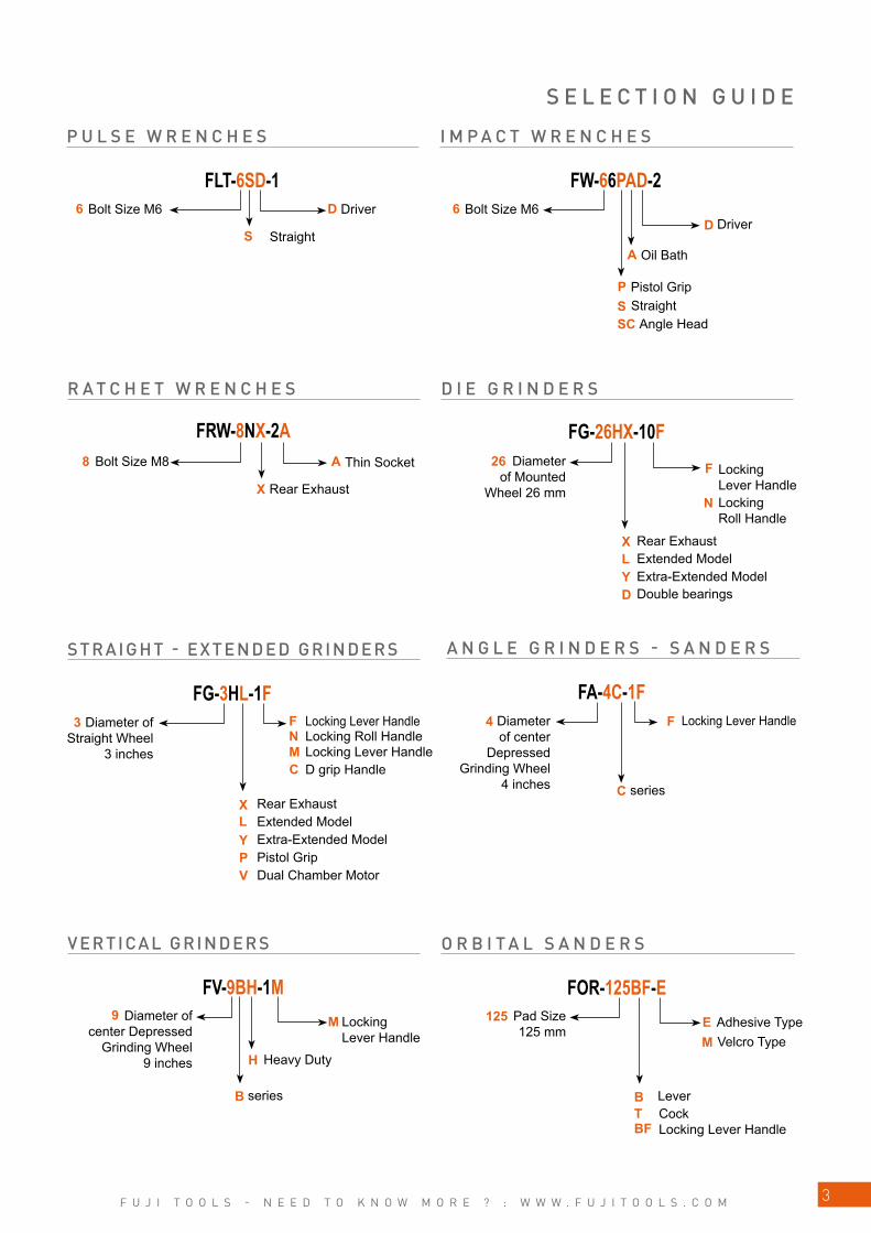
How to understand Fuji model numbersThe model number of Fuji tools is formed by three elements of a combination of letters and numbers indicating the various properties and characteristics of tools concerned. The first combination of letters indicates the group category that the model belongs to. "FRD" of the model FRD-6PH-3, for example, indicates that this model belongs to the group of "Fuji Rotary Drill". The second part "6PH" shows the capacity in numbers like wheel size, bolt size, horse power etc. and also shows the types of throttle handle, exhaust direction and housing etc. in letters. In this case, "6" indicates drilling capacity and "PH" indicates pistol handle and rear exhaust. The third part "3" shows the generation of models in numbers and types of handle, length of anvil and driver bit etc. in letters.
TORQUE TESTERS
GRINDERS - SANDERS
HAMMERS - CHIPPERS - RAMMERS
WRENCHES, SCREWDRIVERS
DRILLS - TAPPERS
OTHER PRODUCTS
FDM Fuji Digital TachometerFDT Fuji Digital Torque TesterFFA Fuji Fastening AdapterFFC Fuji Fastening ControllerFJT Fuji Hydraulic Torque Tester FMC Fuji Multiple Fastening ControllerTT Torque Transducer
FA Fuji Angle GrindersFBS Fuji Belt SandersFG Fuji Die Grinders or Straight GrindersFOS Fuji Orbital SandersFOR Fuji Orbital Sanders (Random)FV Fuji Vertical GrindersTURBO Turbo Ginder
FC Fuji Calking HammersFCH Fuji Chipping HammersFNS Fuji Needle ScalersFR Fuji RammersFRH Fuji Riveting HammersFS Fuji Scaling Hammers
CA Corner Attachments for Impact WrenchesFD Fuji ScrewdriversFET Fuji Electronic Torque Control Pulse WrenchesFOW Fuji Open Ratchet WrenchesFLT/FPT Fuji Mechanical Shut-off Pulse WrenchesFL/FPW Fuji Pulse WrenchesFRW Fuji Ratchet WrenchesFW Fuji Impact Wrenches
FCD Fuji Corner DrillsFRD Fuji Rotary DrillsFT Fuji Tappers
FBM Fuji Pipe Beveling Machines / Chamfering MachinesFJP Fuji Jet PumpsFM Fuji Air MotorFP Fuji PumpsFRF/FRS Fuji Reciprocating File & SawFTD Fuji Tip Dressers
S E L E C T I O N G U I D E
F U J I T O O L S - N E E D T O K N O W M O R E ? : W W W . F U J I T O O L S . C O M 3
S
6
8
6
FLT-6SD-1 FW-66PAD-2D
A
PSSC
X
A 26 F
N
XLYD
3 F
X
N
L
M
Y
C
PV
F4
C
FRW-8NX-2A FG-26HX-10F
FG-3HL-1F FA-4C-1F
FV-9BH-1M FOR-125BF-E
B
H
9 125M
BTBF
EM
P U L S E W R E N C H E S
R A T C H E T W R E N C H E S
S TRAIGHT - EXTENDED GRINDERS
I M P A C T W R E N C H E S
D I E G R I N D E R S
Bolt Size M6
Bolt Size M8
Diameter of Straight Wheel
3 inches
Bolt Size M6
Diameter of Mounted
Wheel 26 mm
Driver
Locking Lever Handle Locking Roll Handle Locking Lever HandleD grip Handle
Driver
Locking Lever Handle Locking Roll Handle
Straight
Rear Exhaust
Rear ExhaustExtended ModelExtra-Extended ModelPistol GripDual Chamber Motor
Pistol Grip
Rear ExhaustExtended ModelExtra-Extended ModelDouble bearings
S E L E C T I O N G U I D E
A N G L E G R I N D E R S - S A N D E R S
Diameter of center
Depressed Grinding Wheel
4 inches
Locking Lever Handle
series
VERTICAL GRINDERS
Diameter of center Depressed
Grinding Wheel 9 inches
Locking Lever Handle
series
Heavy Duty
O R B I T A L S A N D E R S
Pad Size 125 mm
Adhesive TypeVelcro Type
LeverCock Locking Lever Handle
D
Straight
Thin Socket
Angle Head
Oil Bath

F U J I T O O L S - N E E D T O K N O W M O R E ? : W W W . F U J I T O O L S . C O M4
C
PSXZ
FRD-16Z-1C FT-6BX-1
16
F
6 XZ
20
FCH-20F FC-2Z-11,H,32,R,4
2
FR-22L-2FFRH-3-1
12
3
F
FB
PB
T A P P E R S
C A L K I N G H A M M E R SC H I P P I N G H A M M E R S
Tapping Capacity 6mm
Rear Exhaust
Hex Chisel Shank
Locking Lever Handle
Floor TypeBench Type
D grip Handle
Round Chisel ShankFlux Chisel
Hex Chisel ShankRound Chisel Shank
Pistol Grip
Stroke 2 inches
Piston Diameter 22mm
Piston Diameter 20mm
Riveting Capacity 3mm
Twin-lever
S E L E C T I O N G U I D E
D R I L L S
Inside Lever Handle
Drilling Capacity 16mm
Pistol GripStraightRear ExhaustD grip Handle
22
R A M M E R SL I G H T H A M M E R S

F U J I T O O L S - N E E D T O K N O W M O R E ? : W W W . F U J I T O O L S . C O M 5
FP-20-1F-6SM-5R
FBM-80A-6
R5
S
6
80
6
3
P I P E B E V E L L I N G M A C H I N E S
P U M P SA I R M O T O R S
Set Number
Reversible
Motor SizeStraight
Rotational Frequency 500 min-1
S E L E C T I O N G U I D E
Capacity Pipe Inside Diameter 80mm
Discharge Head 20mm
F U J I T O O L S - N E E D T O K N O W M O R E ? : W W W . F U J I T O O L S . C O M6
S E L E C T I O N G U I D E
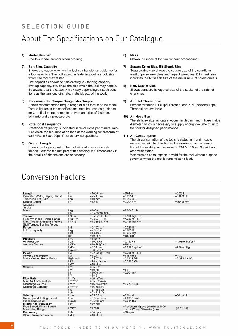
Length 1 m =1000 mm =39.4 in =3.28 ftDiameter, Width, Depth, Height 1 in =25.4 mm =0.0254 m =0.0833 ftThickness, Lift, Size 1 cm =10 mm =0.394 inSide to Center 1 ft =12 in =0.3048 m =304.8 mmCapacityStrokeMass 1 kg =1000 g =2.20462 lb
1 lb =0.45359237 kgTorque 1 N • m =0.7375 ft • lb =0.102 kgf • mRecommended Torque Range 1 kgf • m =9.807 N • m =7.233 ft • lbMax. Torque, Measuring Range 1 ft • lb =1.3558 N • m =0.138 kgf • mStall Torque, Starting TorqueForce 1 N =0.102 kgf =0.225 lbfLifting Capacity 1 kgf =9.807 N =0.205 lbf
1 lbf =4.448 N =0.454 kgf1kN =1000 N =102 kgf
Pressure 1 Pa =1 N/m2
Air Pressure 1 bar =100 kPa =0.1 MPa =1.0197 kgf/cm2
Vaccum Degree 1 MPa =10.2kfg/cm2 =10 bar1 kPa =0.01 bar =0.0102 kp/cm2 =7.5 mmHg1 kp/cm2 =98.07 kPa
Power 1 W =0.102 kgf • m/s =0.738 ft • lb/sPower Consumption 1 W =1 J/s =1 N • m/s =1VAMotor Output, Horse Power 1kgf • m/s =9.807 W =0.0133 PS =7.233 ft • lb/s
1 PS =75 kgf • m/s =0.7355 kW1 kW =1000 W
Volume 1 m3 =35.3 ft3
1 m3 =1000 =1 k1 =1000 cm3 =0.001 m3
1 ft3 =28.3Flow Rate 1 m3/s =60 m3/minMax. Air Consumption 1 m3/min =35.3 ft3/minDischarge Volume 1 m3/h =16.667 /min =0.2778 /sDischarge Capacity 1 m3/min =16.667 /s
1 /s =2.1189 cfm1 cfm =0.4719 /s
Velocity 1 m/s =3.28 ft/s =3.6km/h =60 m/minRope Speed, Lifting Speed 1 ft/s =0.3048 m/s =1.0973 km/hPropelling Speed 1 km/h =0.278 m/s =0.911 ft/sRotational Frequency 1 s-1 =60 rpmFree Speed, Pinion SpeedMeasuring Range 1 min-1 =1 rpm =Peripheral Speed (m/min) x 1000
x Wheel Diameter (mm) ( =3.14)Frequency 1 Hz =60 bpm =60 spmBlow, Stroke per minute 1 kHz =1000 Hz
About The Specifications on Our Catalogue
Conversion Factors
1) Model Number Use this model number when ordering.
2) Bolt Size, Capacity Shows the capacity, which the tool can handle, as guidance for
a tool selection. The bolt size of a fastening tool is a bolt size which the tool may fasten. The capacities shown on this catalogue - tapping capacity, riveting capacity, etc. show the size which the tool may handle. Be aware, that the capacity may vary depending on such condi-tions as the tension, joint rate, material, etc. of the work.
3) Recommended Torque Range, Max Torque Shows recommended torque range or max torque of the model. Torque figures in the specifications must be used as guidance only, as final output depends on type and size of fastener, joint rate and air pressure etc.
4) Rotational Frequency Rotational frequency is indicated in revolutions per minute, min-1 at which the tool runs at no load at the working air pressure of 0.63MPa, 6.3bar, 90psi if not otherwise specified.
5) Overall Length Shows the longest part of the tool without accessories at-tached. Refer to the last part of this catalogue «Dimensions» if the details of dimensions are necessary.
6) Mass Shows the mass of the tool without accessories.
7) Square Drive Size, Bit Shank Size Square drive size shows the square size of the spindle or anvil of pulse wrenches and impact wrenches. Bit shank size indicates the bit shank size of the driver anvil of screw drivers.
8) Hex. Socket Size Shows standard hexagonal size of the socket of the ratchet wrenches.
9) Air Inlet Thread Size Female threaded PT (Pipe Threads) and NPT (National Pipe Threads) are available.
10) Air Hose Size The air hose size indicates recommended minimum hose inside diameter which is necessary to supply enough volume of air to the tool for designed performance.
11) Air Consumption The air consumption of the tools is stated in m3/min, cubic meters per minute. It indicates the maximum air consump-tion at the working air pressure 0.63MPa, 6.3bar, 90psi if not otherwise stated.
Maximum air consumption is valid for the tool without a speed governor when the tool is running at no load.
F U J I T O O L S - N E E D T O K N O W M O R E ? : W W W . F U J I T O O L S . C O M 7
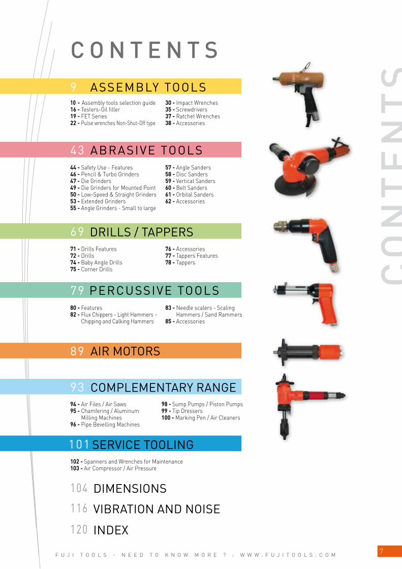
43
93
89
79
69
9
101
116
120
104
CO
NT
EN
TS
44 - Safety Use - Features46 - Pencil & Turbo Grinders47 - Die Grinders49 - Die Grinders for Mounted Point50 - Low-Speed & Straight Grinders53 - Extended Grinders55 - Angle Grinders - Small to large
57 - Angle Sanders58 - Disc Sanders59 - Vertical Sanders60 - Belt Sanders61 - Orbital Sanders62 - Accessories
71 - Drills Features72 - Drills74 - Baby Angle Drills 75 - Corner Drills
76 - Accessories77 - Tappers Features78 - Tappers
80 - Features82 - Flux Chippers - Light Hammers -
Chipping and Calking Hammers
83 - Needle scalers - Scaling Hammers / Sand Rammers
85 - Accessories
94 - Air Files / Air Saws95 - Chamfering / Aluminum
Milling Machines96 - Pipe Bevelling Machines
98 - Sump Pumps / Piston Pumps99 - Tip Dressers100 - Marking Pen / Air Cleaners
102 - Spanners and Wrenches for Maintenance103 - Air Compressor / Air Pressure
10 - Assembly tools selection guide16 - Testers-Oil filler19 - FET Series22 - Pulse wrenches Non-Shut-Off type
30 - Impact Wrenches35 - Screwdrivers37 - Ratchet Wrenches38 - Accessories
C O N T E N T SASSEMBLY TOOLS
ABRASIVE TOOLS
DRILLS / TAPPERS
PERCUSSIVE TOOLS
COMPLEMENTARY RANGE
SERVICE TOOLING
AIR MOTORS
DIMENSIONS
VIBRATION AND NOISE
INDEX

F U J I T O O L S - N E E D T O K N O W M O R E ? : W W W . F U J I T O O L S . C O M8
N O T E S
F U J I T O O L S - N E E D T O K N O W M O R E ? : W W W . F U J I T O O L S . C O M 9
ASSEMBLY TOOLS
SELECTION GUIDE ____________________________________________________________ 10
ASSEMBLY TOOLS SELECTION GUIDE ___________________________ 14
TESTERS-OIL FILLER ________________________________________________________ 16
FET SERIES __________________________________________________________________________ 19
PULSE WRENCHES NON-SHUT-OFF TYPE __________________ 22
IMPACT WRENCHES _________________________________________________________ 30
SCREWDRIVERS _________________________________________________________________ 35
RATCHET WRENCHES _______________________________________________________ 37
ACCESSORIES ____________________________________________________________________ 38

F U J I T O O L S - N E E D T O K N O W M O R E ? : W W W . F U J I T O O L S . C O M
M4 M5 M6 M8 M10 M12 M14 M16 M18
20 40 60 80 100 120 140 160 180 200 4000
0 20 30 40 60 80 100 120 140 160 180 200 400 500
M4 M5 M6 M8 M10 M12 M14 M16 M22M18 M20
10
RECOMMENDED TORQUE RANGEThe torque requirement is one of the major factors to be considered when selecting fastening tools. The following graphic presentation shows the recommended torque range of our assembly tools. This is to be used for guidance only as final torque may vary depending in the type and size of the fastener, the joint rate, air pressure, etc.Optimum performance is achieved at the mid range of the tool’s torque capability.
Bolt Size Bolt Grade Bolt Size Bolt Grade
mm 3.0 4.6 4.8 5.8 8.8 10.9 12.9 mm 4.6 4.8 5.8 8.8 10.9 12.9M2 0.10 0.13 0.17 0.22 0.35 0.49 0.58 M18 103 121 172 275 386 463
M3 0.35 0.46 0.61 0.77 1.20 1.70 2.10 M20 144 170 240 385 541 649
M4 0.81 1.10 1.40 1.80 2.90 4.00 4.90 M22 194 230 324 518 728 874
M5 0.60 2.20 2.95 3.60 5.70 8.10 9.70 M24 249 295 416 665 935 1120
M6 2.80 3.70 4.90 6.10 9.80 14.0 17.0 M27 360 435 600 961 1350 1620
M8 8.9 10.5 15 24 33 40 M30 492 590 819 1310 1840 2210
M10 17 21 29 47 65 79 M36 855 1030 1420 2280 3210 3850
M12 30 36 51 81 114 136 M42 1360 2270 3640 5110 6140
M14 48 58 80 128 181 217 M45 1690 2820 4510 6340 7610
M16 74 88 123 197 277 333 M48 2040 3400 5450 7660 9190
TIGHTENING TORQUE (N.m)This table shows the recommended tightening torque for common bolt size M2 to M48.
S E L E C T I O N G U I D E
ELECTRONIC TORQUE CONTROL PULSE WRENCHES (P.19)
PULSE WRENCHES NON SHUT-OFF TYPE (P.22)
Bolt Grade at 8.8
Bolt Grade at 8.8
MODELPISTOL-SQUARE DRIVE
FET-4-1 FET-5-1 FET-6-1 FET-7-1 FET-9-1
FET-11-1 FET-13-1 FET-16-1
MODELSQUARE DRIVE TYPE
FL-4-1FL-5-1 FL-6-1 FL-7-1 FL-9-1
FL-11-1FL-13-1
FL-4D-1(10)FL-5D-1(10) FL-6D-1(10)FPW-110-1
FPW-110D-1(10)FPW-1660-1
PISTOL-BIT SHANKFET-4D-1FET-5D-1FET-6D-1
STRAIGHT BIT SHANKFPW-110SD-1(10)FPW-330SD-1(10)
FL-4SD-1(10) FL-5SD-1(10)FL-6SD-1(10)
STRAIGHT-SQUARE DRIVEFPW-2220S-1
FPW-110S-1 FPW-330S-1 FPW-770S-1
FL-4S-1FL-5S-1FL-6S-1
ANGLE SQUARE DRIVEFPW-440SC-1FPW-550SC-1FPW-660SC-1FPW-770SC-1
GEARED-HEX SOCKETFPW-770SCG-1
according to ISO898-1
TORQUE (N•M)
TORQUE (N•M)
ASS
EMB
LY T
OO
LS

F U J I T O O L S - N E E D T O K N O W M O R E ? : W W W . F U J I T O O L S . C O M 11
S E L E C T I O N G U I D E
0 20 40 60 80 100 120 140 160 180 200 400
M4 M5 M6 M8 M10 M12 M14 M16 M18
0 50 100 150 200 250 300
M4 M5 M6 M8 M10 M12 M14 M16
0 50 100 150 200 250 300
M4 M5 M6 M8 M10 M12 M14 M16
M4 M5 M6 M8 M10 M12 M14 M16
0 50 100 150 200 250 300
PULSE WRENCHES SHUT-OFF TYPE (P.26)Bolt Grade at 8.8
MODELSTRAIGHT-SQUARE DRIVE
FPT-110S-1FPT-330S-1FPT-770S-1
FLT-4S-1FLT-5S-1
FLT-5S-1LFLT6S-1
FLT6S-1L
SQUARE DRIVE TYPEFPT-110-1
FLT-4-1 FLT-5-1 FLT-6-1 FLT-7-1 FLT-9-1
FLT-11-1 FLT-13-1
FLT-20S-1 FPT-1660-1
BIT SHANKFPT-110D-1(10)
FLT-4D-1(10)FLT-5D-1(10)FLT-6D-1(10)
STRAIGHT BIT CHANGEFPT-110SD-1(10)FPT-330SD-1(10)
FLT-4SD-1(10)FLT-5SD-1(10)
FLT-5SD-1L(10)FLT-6SD-1(10)
FLT-6SD-1L(10)
ANGLE SQUARE DRIVEFPT-440SC-1FPT-550SC-1FPT-660SC-1FPT-770SC-1
TORQUE (N•M)
GEARED-HEX SOCKETFPT-770SCG-1
IMPACT WRENCHES - SMALL SIZE (P.30-32)
Bolt Grade at 8.8
Bolt Grade at 8.8
Bolt Grade at 8.8
STRAIGHTFW-44SA-1FW-66SA-1
ANGLEFW-6SCX-6FW-8SCH-2
MODELPISTOL GRIPFW-44PA-2
FW-66PA-2FW-88P-1
MODELPISTOL GRIP
FW-5PX-6FW-6PM-1FW-6PL-1FW-6PX-5FW-6PX-6FW-6PH-1
FW-6PH-11FW-8PH-3
FW-10PH-1FW-10PH-2FW-14PX-5FW-14PH-1FW-14PH-2FW-14PH-3
MODELSTRAIGHTFW-6SX-5FW-6SX-6FW-8SH-2
FW-10SX-5FW-14SX-5
TORQUE (N•M)
TORQUE (N•M)
TORQUE (N•M)
ASS
EMB
LY T
OO
LS

F U J I T O O L S - N E E D T O K N O W M O R E ? : W W W . F U J I T O O L S . C O M
M16 M18 M20 M22 M24 M27 M30 M36
0 500 1000 1500 2000 2500 3000
M16 M18 M20 M22 M24 M27 M30 M36
0 500 1000 1500 2000 2500 3000
0 2500 5000 7500 10000 12500 15000 17500 20000 22500 25000
M45M42 M48
12
IMPACT WRENCHES MEDIUM SIZE (P.33-34)
IMPACT WRENCHES LARGE SIZE (P.34)
Bolt Grade at 8.8
Bolt Grade at 8.8
Bolt Grade at 8.8
MODELSTRAIGHT
FW-50-7FW-75-7
FW-100-1
MODELSTRAIGHT
FW-19Z-5FW-19Z-5C
FW-250-1FW-250-1C
FW-250-2FW-250-2C
FW-320-1FW-320-1CFW-320-1L
FW-320-1CLFW-420-1
FW-420-1CFW-420-1L
FW-420-1CLFW-420-2
FW-420-2C
MODELPISTOL GRIP
FW-19PX-5FW-250P-1FW-250P-2FW-320P-1FW-420-2C
TORQUE (N•M)
TORQUE (N•M)
TORQUE (N•M)
S E L E C T I O N G U I D E
ASS
EMB
LY T
OO
LS
F U J I T O O L S - N E E D T O K N O W M O R E ? : W W W . F U J I T O O L S . C O M 13
M4M3 M5 M6 M8 M10
0 5 10 15 20 25 30 35 40 45 50
0 5 10 15 20 25 30 35 40 45 50
M4M3 M5 M6 M8 M10
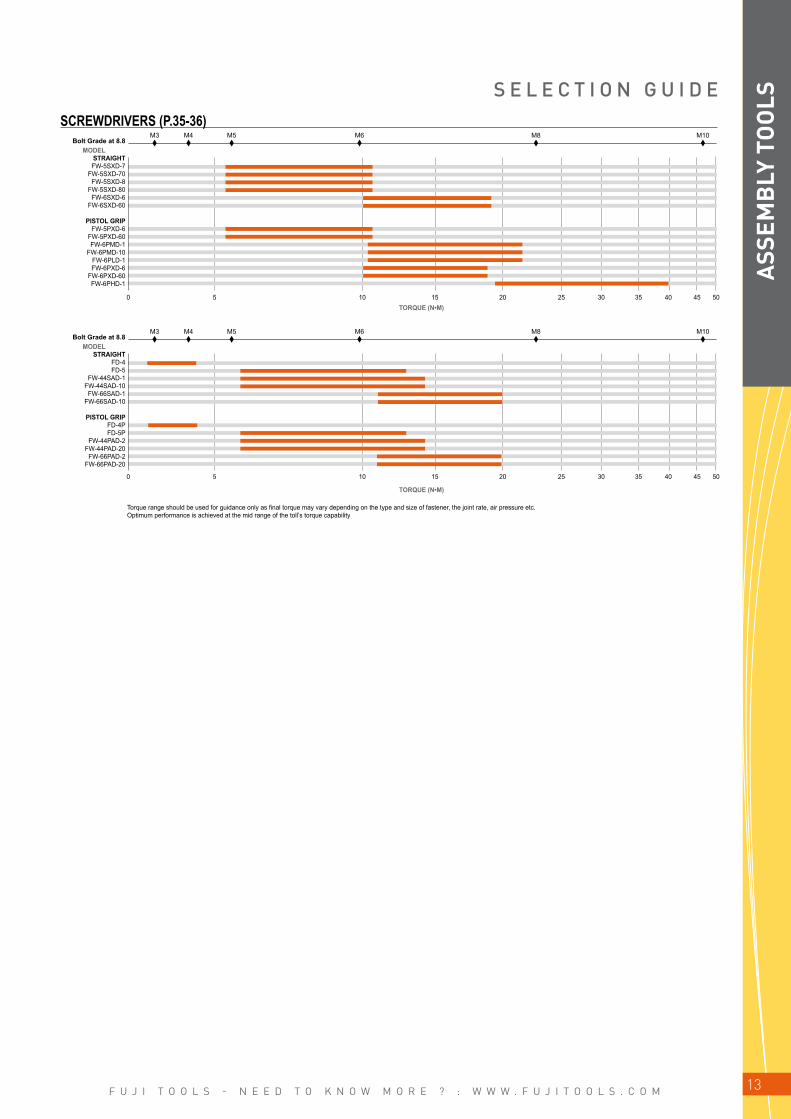
SCREWDRIVERS (P.35-36)Bolt Grade at 8.8
Bolt Grade at 8.8
MODELSTRAIGHTFW-5SXD-7
FW-5SXD-70FW-5SXD-8
FW-5SXD-80FW-6SXD-6
FW-6SXD-60
PISTOL GRIPFW-5PXD-6
FW-5PXD-60FW-6PMD-1
FW-6PMD-10FW-6PLD-1FW-6PXD-6
FW-6PXD-60FW-6PHD-1
MODELSTRAIGHT
FD-4FD-5
FW-44SAD-1FW-44SAD-10FW-66SAD-1
FW-66SAD-10
PISTOL GRIPFD-4PFD-5P
FW-44PAD-2FW-44PAD-20FW-66PAD-2
FW-66PAD-20
TORQUE (N•M)
Torque range should be used for guidance only as final torque may vary depending on the type and size of fastener, the joint rate, air pressure etc. Optimum performance is achieved at the mid range of the toll’s torque capability
S E L E C T I O N G U I D E
TORQUE (N•M)
ASS
EMB
LY T
OO
LS

F U J I T O O L S - N E E D T O K N O W M O R E ? : W W W . F U J I T O O L S . C O M14
9.5
12
13
16
A S S E M B L Y T O O L S F E A T U R E S
EXHAUST WITH A MUFFLER
TWO STAGE - SQUEEZING TYPE THROTTLE VALVE MECHANISM
REVERSE VALVE LEVER
AIR REGULATOR
SQUARE DRIVE ANVIL
BIT SHANK TYPE ANVIL FOR SCREW DRIVERS
CLUTCH MECHANISM-IMPACT WRENCHES AND DRIVERS
Our original built-in, swivel type, exhaust muffler is designed to reduce the noise level of the tool. The operator can also select a suitable direction of the exhaust air to minimise the risk of blowing any dust or debris in to the local work environment. All WRENCHES EXCEPT FW-6PL, 6PLD, 5SXD-8, 80, FD-4, 5, 4P, 5P
The two stage / squeeze type throttle enables the operator to start the tool slowly and increase to full speed to aid location of the fastening at the start of the cycle.
All models feature a reversible motor. The operator can easily and quickly select the direction of rotation simply by turning or sliding the reverse actuator.
ALL WRENCHES EXCEPT FOW, FRW
To accommodate torque adjustment, the built in air regulator is used to regulate the air flow.
Two types of square drive anvils are available. As our standard for overseas, the models larger than 25.4 mm (1 inch) square drive are supplied with P anvil (Pin hole retainer type) and the models smaller than 19 mm (3/4 inch) square drive are supplied with BF anvil (Flat button retainer type). Small models can be supplied with P anvil on your request.
Two types of quick-change bit shank type anvils are available.Both are for 6.35 mm (1/4 inch) hex driver bit, but divided into two model groups according to the bit neck size.ALL SCREW DRIVERS
n DOUBLE CLUTCH TYPEThe impact force is balanced with less torque reaction due to two impacts made per revolution.The double clutch type impact wrenches and drivers benefit from less vibration and longer service life than conventional single clutch models.
REAR EXHAUST MUFFLER
FPW PISTOL, STRAIGHT
FW PISTOL, STRAIGHT
FRONT EXHAUSTFPW-2220S, FW-19Z,
250~420, FW-50, 75, 100
n SINGLE CLUTCH TYPEThe impact force is harder and torque/weight ratio is better than the double clutch type. Single clutch type models are suitable for hard «pull-up» fastening operations for maintenance & service applications.
Hammer Clutch
Cam
Clutch Frame
Clutch Pin
Anvil
(1) GROUPS (2) GROUPS
Clutch PinHammer Clutch
Cam
Clutch Frame
Anvil
ASS
EMB
LY T
OO
LS
F U J I T O O L S - N E E D T O K N O W M O R E ? : W W W . F U J I T O O L S . C O M 15
A S S E M B L Y T O O L S F E A T U R E S
HANDLE PROTECTOR
DUAL CHAMBER MOTOR
2-BLADE PULSE UNIT
Ergonomically designed handle protectors provide reduced vibration, increased operator comfort and insulate the hand from the cold temperature generated by compressed air.
All Fuji pulse wrench models (FET, FLT, FPT, FL, FPW) and the series of impact wrenches (FW-44~88) are built with a 9 blade, dual chamber motor. This motor is designed to provide high torque at low speed, giving the best characteristics for fast reliable and accurate tightening.
As the pulsing cycle is very short, there is almost no torque reaction in the handle grip (low motor torque only is felt by the operator). Unlike an impact wrench, the pulse tool has no «metal to metal» contact and consequently the pulse wrenches provide softer and stable «impulsing». The benefits from this are less vibration, lower noise levels and longer service life when compared with conventional impact wrenches.All pulse wrenches models (FET, FLT, FPT, FL, FPW) utilise the Fuji patented 2 blade pulse unit combined with the dual chamber motor. This combination provides 50% higher power to weight ratio than comparable fastening tools. For productivity, this design reaches torque faster, is excellent for soft joint or prevailing torque applications with reduced noise and vibration levels.
Cam Clutch ShaftSpring
Anvil Hammer Clutch
CROSS SECTION EFFICIENCY COMPARISON
Dual Chamber Motor
Dual Chamber Motor
Speed (min-1)
TOR
QU
E (T
)
High Speed High Torque Operation for Super
Productivity
Conventional Motor
Single Chamber Motor
Outlet
Outlet
OutletInlet
Inlet
Inlet
Air Motor Torque in Pulsing
Air Motor Speed in Pulsing
n<N
n<N
IMPULSING CYCLE2-BLADE PULSE UNIT Controllers - Testers
High Pressure
Impulsing
Non-Impulsing
High Pressure
Low Pressure
Low Pressure
R
R
R
0°
270°180°
90°
n 2-JAW ONE-DOG CLUTCH TYPEThe Fuji 2-Jaw clutch impact wrenches generate very high torque/weight. These types of tool are most suited for tightening prevailing torque bolts and for removing corroded fasteners.
ASS
EMB
LY T
OO
LS
F U J I T O O L S - N E E D T O K N O W M O R E ? : W W W . F U J I T O O L S . C O M16
TT-20TT-50
TT-150
TT-300
FDT-2-1
TT-500 TT-1000
FJT-5-1~5C-1
FJT-10-1~10C-1
FJT-16-1~16C-1
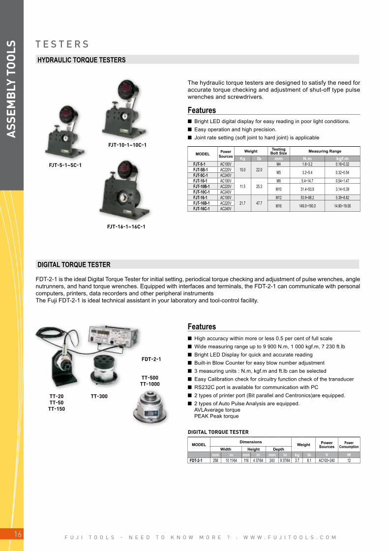
HYDRAULIC TORQUE TESTERS
DIGITAL TORQUE TESTER
The hydraulic torque testers are designed to satisfy the need for accurate torque checking and adjustment of shut-off type pulse wrenches and screwdrivers.
n Bright LED digital display for easy reading in poor light conditions. n Easy operation and high precision. n Joint rate setting (soft joint to hard joint) is applicable
n High accuracy within more or less 0.5 per cent of full scale n Wide measuring range up to 9 900 N.m, 1 000 kgf.m, 7 230 ft.lb n Bright LED Display for quick and accurate reading n Built-in Blow Counter for easy blow number adjustment n 3 measuring units : N.m, kgf.m and ft.lb can be selected n Easy Calibration check for circuitry function check of the transducer n RS232C port is available for communication with PC n 2 types of printer port (Bit parallel and Centronics)are equipped. n 2 types of Auto Pulse Analysis are equipped. AVLAverage torque PEAK Peak torque
Features
Features
MODEL Power Sources
Weight Testing Bolt Size Measuring Range
Kg lb mm N.m kgf.mFJT-5-1 AC100V
10.0 22.0M4 1.6~3.2 0.16~0.32
FJT-5B-1 AC220V M5 3.2~5.4 0.32~0.54FJT-5C-1 AC240VFJT-10-1 AC100V
11.5 25.3M6 5.4~14.7 0.54~1.47
FJT-10B-1 AC220V M10 31.4~53.9 3.14~5.39FJT-10C-1 AC240VFJT-16-1 AC100V
21.7 47.7M12 53.9~88.2 5.39~8.82
FJT-16B-1 AC220V M16 149.0~190.0 14.90~19.00FJT-16C-1 AC240V
T E S T E R S
FDT-2-1 is the ideal Digital Torque Tester for initial setting, periodical torque checking and adjustment of pulse wrenches, angle nutrunners, and hand torque wrenches. Equipped with interfaces and terminals, the FDT-2-1 can communicate with personal computers, printers, data recorders and other peripheral instrumentsThe Fuji FDT-2-1 is ideal technical assistant in your laboratory and tool-control facility.
MODELDimensions
Weight Power Sources
Power ConsumptionWidth Height Depth
mm in mm in mm in kg lb V WFDT-2-1 258 10 11/64 116 4 37/64 243 9 37/64 3.7 8.1 AC100~240 12
DIGITAL TORQUE TESTER
ASS
EMB
LY T
OO
LS
F U J I T O O L S - N E E D T O K N O W M O R E ? : W W W . F U J I T O O L S . C O M 17
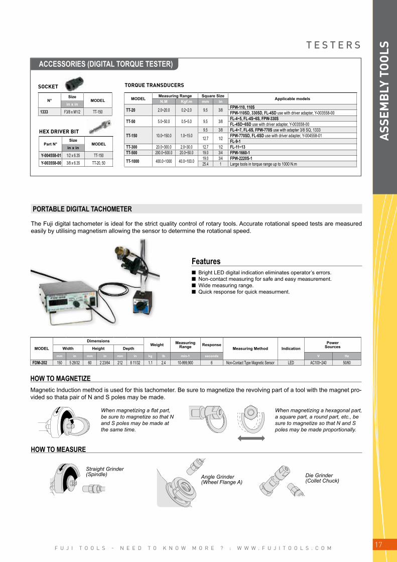
ACCESSORIES (DIGITAL TORQUE TESTER)
T E S T E R S
N°Size
MODELin x in
1333 F3/8 x M1/2 TT-150
Part N°Size
MODELin x in
Y-004558-01 1/2 x 6.35 TT-150Y-003558-00 3/8 x 6.35 TT-20, 50
SOCKET
HEX DRIVER BIT
TORQUE TRANSDUCERS
MODELMeasuring Range Square Size
Applicable modelsN.M Kgf.m mm in
TT-20 2.0~20.0 0.2~2.0 9.5 3/8 FPW-110, 110SFPW-110SD, 330SD, FL-4SD use with driver adapter, Y-003558-00
TT-50 5.0~50.0 0.5~5.0 9.5 3/8 FL-4~5, FL-4S~6S, FPW-330S FL-4SD~6SD use with driver adapter, Y-003558-00
TT-150 10.0~150.0 1.0~15.09.5 3/8 FL-4~7, FL-6S, FPW-770S use with adapter 3/8 SQ, 1333
12.7 1/2 FPW-770SD, FL-6SD use with driver adapter, Y-004558-01FL-9-1
TT-300 20.0~300.0 2.0~30.0 12.7 1/2 FL-11~13TT-500 200.0~500.0 20.0~50.0 19.0 3/4 FPW-1660-1
TT-1000 400.0~1000 40.0~100.0 19.0 3/4 FPW-2220S-125.4 1 Large tools in torque range up to 1000 N.m
ASS
EMB
LY T
OO
LS
PORTABLE DIGITAL TACHOMETER
The Fuji digital tachometer is ideal for the strict quality control of rotary tools. Accurate rotational speed tests are measured easily by utilising magnetism allowing the sensor to determine the rotational speed.
Features n Bright LED digital indication eliminates operator’s errors. n Non-contact measuring for safe and easy measurement. n Wide measuring range. n Quick response for quick measurment.
HOW TO MAGNETIZEMagnetic Induction method is used for this tachometer. Be sure to magnetize the revolving part of a tool with the magnet pro-vided so thata pair of N and S poles may be made.
When magnetizing a flat part, be sure to magnetize so that N and S poles may be made at the same time.
When magnetizing a hexagonal part, a square part, a round part, etc., be sure to magnetize so that N and S poles may be made proportionally.
HOW TO MEASURE
Straight Grinder (Spindle) Angle Grinder
(Wheel Flange A)Die Grinder (Collet Chuck)
MODEL
DimensionsWeight Measuring
Range ResponseMeasuring Method Indication
Power SourcesWidth Height Depth
mm in mm in mm in kg lb min-1 seconds V Hz
FDM-202 150 5 29/32 60 2 23/64 212 8 11/32 1.1 2.4 10-999,900 6 Non-Contact Type Magnetic Sensor LED AC100~240 50/60

F U J I T O O L S - N E E D T O K N O W M O R E ? : W W W . F U J I T O O L S . C O M18
220
214
FVT-1
TOOLSFW
FOW FRW
FL FPW
FLT FPT FET FW FL
FPWFLT FPT FET
CONTROLLER - - - FET-100 - - - FET-100COUNTDOWN ADAPTERS - - - - FFA FFA FFA FFATORQUE ADJUSTMENT x x x xSHUT-OFF M T TI TI M T
DISPLAYFASTENING OK/NOK x x x x xFASTENING OK/NOK x x
DISPLAY INPUT/OUTPUT
OK/NOK x x x x xLINE INTEGRATION x x x x xNOK REASON x x
ERROR PROOFING
BOLT COUNTING x x x x xTIME LIMITS x x x x xPULSE COUNTING x xTORQUE JUDGEMENT x x
DATA MEMORY x x
DATA OUTPUTRS232 x xETHERNET x x
TORQUE CONTROL SYSTEMTo accommodate the various requirements of torque control and assembly application, Fuji offers a complete range of faste-ning tools and reliable torque controllers designed to enhance quality and increase productivity. The following table shows various combinations of fastening tools and controllers. Choose the correct combination to meet your production requirements.
O I L F I L L E R - T E S T E R S
ASS
EMB
LY T
OO
LS
OIL FILLER
COUNTDOWN ADAPTER
The Fuji oil filler is the ideal, and indispensable, equipment required for maintenance and repair of pulse wrenches. By connec-ting a conventional air supply to the handle valve, the oil filler makes re-filling the pulse unit assembly quick and easy.
10 mm more
INOFF
ONHandle Valve
Vacuum Pressure Gauge
Spindle
Stand
OilPulseAss’y
Lid
The Fuji FFA-2-2 Countdown Adapter counts the number of bolts tightened. It is used together with FLT & FPT Shut-off Pulse Wrenches (CD type) and FL & FPW Pulse Wrenches and lifts the error proofing capabilities of these tools.Optional devices like Buzzer or Light tower can be connected for quick notice of countdown error, or a signal can be output to the line control system. With its compact size, the FFA-2-2 is easily integrated into the assembly station.
ModelDimensions
Weight Power Sources
Power ConsumptionWidth Height Depth
mm in mm in mm in kg lb V WFFA-2-2 125 4 59/64 62 2 29/64 25 63/64 0.3 0.7 DC24 3
M - Mechanical shut-off - Torque Transducer based shutoff - TI Time based shut off

F U J I T O O L S - N E E D T O K N O W M O R E ? : W W W . F U J I T O O L S . C O M 19
FET-6-1 TOOL
CONTROLLING DYNAMIC TORQUE BY OIL PRESSUREThe Fuji F1 shut off type system wrench is equipped with a torque transducer which enables torque control and monitoring on critical applications.
MINIMIZE TIGHTENING TORQUE SCATTERTightening torque tends to scatter in the soft joint application due to the relaxation of the work.As a solution of scattering Fuji new F1 system continues to tighten 3 more pulses after torque reaches lower limit to make sure the tightening in all conditions.
ModelCapacity
(Bolt size) Recommended Torque Range Square Drive Size Free Speed @0.63MPa
Air Consumption @0.63MPa Weight Overall
Length Air Hose Size
mm Nm kfg.m ft.lb mm in rpm @Load (m3/min) kg mm mm
FET-4-1 M5 to 6 5~12 0.5~1.2 3.6~8.8 9.5 3/8 6,700 0.36 0.96 162 6.3FET-5-1 M6 to 8 11~24 1.1~2.4 8~18 9.5 3/8 6,300 0.40 0.96 162 6.3FET-6-1 M8 to 10 22~35 2.2~3.6 16~26 9.5 3/8 6,700 0.42 1.0 174 9.5FET-7-1 M8 to 10 30~55 3.1~5.6 22~40 9.5 3/8 6,100 0.60 1.2 177 9.5FET-9-1 M10 50~85 5.1~8.7 50~85 9.5 3/8 4,600 0.65 1.6 195 9.5FET-11-1 M10 to 12 70~120 7.1~12.2 52~89 12.7 1/2 5,000 0.80 2.0 207 9.5FET-13-1 M12 to 14 90~155 9.2~15.8 66~115 12.7 1/2 3,800 0.85 2.3 217 9.5FET-16-1 M16 to 18 150~210 15.3~21.4 111~155 19 3/4 3,000 1.20 4.1 262 9.5
ModelCapacity
(Bolt size) Recommended Torque Range Bit Shank Size Free Speed @0.63MPa
Air Consumption @0.63MPa Weight Overall
Length Air Hose Size
mm Nm kfg.m ft.lb mm in rpm @Load (m3/min) kg mm mm
FET-4D-1 M5 to 6 5~12 0.5~1.2 3.6~8.8 6.35 1/4 6,700 0.36 0.96 162 6.3FET-5D-1 M6 to 8 11~22 1.1~2.2 8~16 6.35 1/4 6,300 0.40 0.96 162 6.3FET-6D-1 M8 to 10 19~28 1.9~2.9 14~21 6.35 1/4 6,700 0.42 1.0 174 9.5
Square drive type
Driver bit typeAir Inlet Thread Size: PT or NPT 3/8" except FET-4-1/-5-1: 1/4".
Air Inlet Thread Size: PT or NPT 1/4" except FET-6D-1: 3/8"
FET SeriesF E T S E R I E S S Y S T E M
CONVERT SIGNAL
TO TORQUE VALUE
FET-100-1 CONTROLLER
FET-200-1 COMMANDER
FET SERIES
TAKE THE SIGNAL FROMTRANSDUCER
BUILT IN TOOL
SHUT OFF THE TOOL
TORQUE CONTROL
BATCH COUNTING
ASS
EMB
LY T
OO
LS
F U J I T O O L S - N E E D T O K N O W M O R E ? : W W W . F U J I T O O L S . C O M20
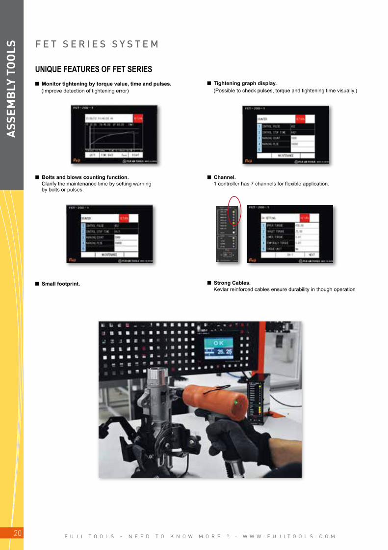
F E T S E R I E S S Y S T E M
UNIQUE FEATURES OF FET SERIES n Monitor tightening by torque value, time and pulses. n Tightening graph display. (Improve detection of tightening error) (Possible to check pulses, torque and tightening time visually.)
n Bolts and blows counting function. n Channel. Clarify the maintenance time by setting warning by bolts or pulses.
1 controller has 7 channels for flexible application.
n Small footprint. n Strong Cables. Kevlar reinforced cables ensure durability in though operation
ASS
EMB
LY T
OO
LS
F U J I T O O L S - N E E D T O K N O W M O R E ? : W W W . F U J I T O O L S . C O M 21
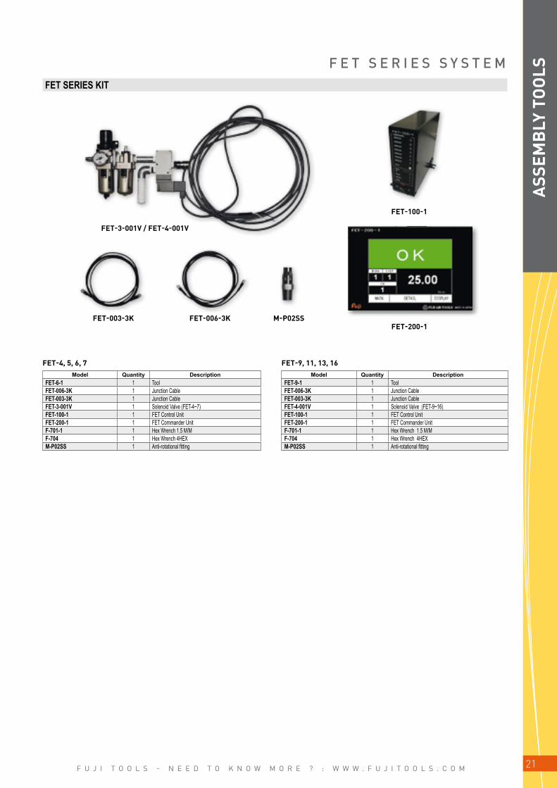
FET-3-001V / FET-4-001V
FET-100-1
FET-003-3K FET-006-3K M-P02SSFET-200-1
FET-4, 5, 6, 7 FET-9, 11, 13, 16
F E T S E R I E S S Y S T E MFET SERIES KIT
Model Quantity DescriptionFET-6-1 1 ToolFET-006-3K 1 Junction CableFET-003-3K 1 Junction CableFET-3-001V 1 Solenoid Valve (FET-4~7)FET-100-1 1 FET Control UnitFET-200-1 1 FET Commander UnitF-701-1 1 Hex Wrench 1.5 M/MF-704 1 Hex Wrench 4HEXM-P02SS 1 Anti-rotational fitting
Model Quantity DescriptionFET-9-1 1 ToolFET-006-3K 1 Junction CableFET-003-3K 1 Junction CableFET-4-001V 1 Solenoid Valve (FET-9~16)FET-100-1 1 FET Control UnitFET-200-1 1 FET Commander UnitF-701-1 1 Hex Wrench 1.5 M/MF-704 1 Hex Wrench 4HEXM-P02SS 1 Anti-rotational fitting
ASS
EMB
LY T
OO
LS

F U J I T O O L S - N E E D T O K N O W M O R E ? : W W W . F U J I T O O L S . C O M22
1
3
2
1
2
3
FL Series
Accumulator Mechanism
Ergonomic Design
Environmentally Friendly Design
ACCUMULATOR MECHANISMThe accumulator functions to compensate against the sudden rise of oil pressure when tightening a hard joint. Torque scatter and error is minimised.As the oil temperature increases during consecutive tightening, the accumulator takes in the expanded vo-lume of oil to maintain a consistent oil volume in the pulse unit. This ensures high tightening torque accuracy.
ENVIRONMENTALLY FRIENDLY DESIGNTo reduce effects on the environment and environmental energy during the life cycle of the tool, no paints is applied to th body of the tool. Consequently, the effect of paint peeling is eliminated. The fully cover protector is designed as standard.
ERGONOMIC DESIGNCompared with conventional tools, weight is kept to a minimum. The grip handle size is optimised to provide enhanced levels of operator comfort. This special grip also absorbs vibration more effectively.Furthermore, reduced noise and vibration levels are standard with the FL series due to the optimised dimensions.
F E A T U R E S
P U L S E W R E N C H E S N O N S H U T - O F F T Y P E
ASS
EMB
LY T
OO
LS

F U J I T O O L S - N E E D T O K N O W M O R E ? : W W W . F U J I T O O L S . C O M 23
FL-4-1 FL-4D-1FL-11-1FL-7-1
A
B
FL-4S-1
FL-4SD-1
ModelBolt Size Recommended Torque Range Free
SpeedSquare Drive Size
Bit Shank SizeOverall Length
(without socket)Weight
(without socket)Air Consumption
(at Load) Air Hose Size
mm N.m kgf.m ft.lb min-1 mm in mm in kg lb m3/min ft3/min mm in
FL-4-1 M6 16~24 1.6~2.4 11.8~17.7 6,700 9.5 3/8 139.5 5 31/64 0.79 1.7 0.36 12.7 6.3 1/4FL-5-1 M6~M8 20~40 2.0~4.0 14.7~29.5 6,300 9.5 3/8 139.5 5 31/64 0.79 1.7 0.40 14.1 6.3 1/4FL-6-1 M8 28~56 2.8~5.6 20.6~41.3 6,700 9.5 3/8 151.5 5 31/32 0.83 1.8 0.42 14.8 9.5 3/8FL-7-1 M8~M10 34~60 3.4~6.1 25.0~44.2 6,100 9.5 3/8 155 6 7/64 1.02 2.2 0.60 21.1 9.5 3/8FL-9-1 M10 52~96 5.3~9.7 38.3~70.8 5,000 12.7 1/2 173 6 13/16 1.45 3.2 0.65 22.9 9.5 3/8FL-11-1 M10~M12 80~136 8.1~13.8 59.0~100.3 5,000 12.7 1/2 184 7 15/64 1.80 4.0 0.80 28.2 9.5 3/8FL-13-1 M12~M14 120~172 12.2~17.5 88.5~126.8 3,800 12.7 1/2 192 7 9/16 2.10 4.6 0.85 30.0 9.5 3/8FL-4D-1(10) M6 14~20 1.4~2.0 10.3~14.7 6,700 6.35 1/4 140 5 3/64 0.79 1.7 0.36 12.7 6.3 1/4FL-5D-1(10) M6~M8 18~32 1.8~3.2 13.2~23.6 6,300 6.35 1/4 140 5 3/64 0.79 1.7 0.40 14.1 6.3 1/4FL-6D-1(10) M8 25~42 2.5~4.2 18.4~30.9 6,700 6.35 1/4 152 5 63/64 0.83 1.8 0.42 14.8 6.3 1/4
P U L S E W R E N C H E S N O N S H U T - O F F T Y P E Recommended Torque Range, Max TorqueShows recommended torque range or max torque of the model. Torque figures in the specifications must be used as guidance only, as final output depends on type and size of bolts and nuts, joint rate and air pressure etc.
PISTOL GRIP MODELS (SQUARE DRIVE - BIT SHANK) Sq. 6.35 mm (1/4") ~ 9.5 mm (3/8") ~ 12.7 mm (1/2")
Air Inlet Thread Size: PT or NPT 1/4".Figures in ( ) can be obtained at the position of " L " mark on the regulartor knob, but for another, at "H" mark.
STRAIGHT MODELS (SQUARE DRIVE) Sq. 9.5 mm (3/8")
ModelBolt Size Recommended Torque Range Free
Speed Square Drive Size Overall Length (without socket)
Weight(without socket)
Air Consumption (at Load) Air Hose Size
mm N.m kgf.m ft.lb min-1 mm in mm in kg lb m3/min ft3/min mm in
FL-4S-1 M6 6~14 0.6~1.4 4.4~10 5,600 9.5 3/8 209 8 15/64 0.85 1.8 0.36 12.7 6.3 1/4FL-5S-1 M6~M8 11~24 1.1~2.4 8~18 6,300 9.5 3/8 209 8 15/64 0.85 1.8 0.40 14.1 6.3 1/4FL-6S-1 M8 21~32 2.1~3.3 16~24 5,600 9.5 3/8 221 8 45/64 0.90 2.0 0.42 14.8 9.5 3/8
Air Inlet Thread Size: PT or NPT 1/4".
STRAIGHT MODELS (BIT SHANK) Hex. 6.35 mm (1/4")
ModelBolt Size Recommended Torque Range Free
Speed Bit Shank Size Overall Length (without socket)
Weight(without socket)
Air Consumption (at Load) Air Hose Size
mm N.m kgf.m ft.lb min-1 mm in mm in kg lb m3/min ft3/min mm in
FL-4SD-1(10) M4~M6 15~25 1.5~2.6 11.1~18.4 5,500 6.35 1/4 226 8 57/64 0.88 1.9 0.35 12.4 6.3 1/4FL-5SD-1(10) M4~M6 20~34 2.0~3.5 14.8~25.1 5,700 6.35 1/4 226 8 57/64 0.88 1.9 0.37 13.1 6.3 1/4FL-6SD-1(10) M6~M8 25~37 2.6~3.8 18.4~27.3 5,800 6.35 1/4 238 9 3/8 0.95 2.1 0.50 17.7 9.5 3/8
Air Inlet Thread Size: PT or NPT 1/4".
FL-***SD-1, FL-***D-1A:9.5mm B:12mm
FL-***SD-10, FL-***D-10A:13mm B:16mm
Bit Size
ASS
EMB
LY T
OO
LS

F U J I T O O L S - N E E D T O K N O W M O R E ? : W W W . F U J I T O O L S . C O M24
FPW-110SD
FPW-2220S-1
FPW-***SD-1, FPW-***D-1A:9.5mm B:12mm
FPW-***SD-10, FPW-***D-10A:13mm B:16mm
A
B
FPW-1100~1660FPW-110-1
STRAIGHT MODELS (SQUARE DRIVE) Sq. 9.5 mm (3/8") ~ 19 mm (3/4")
ModelBolt Size Recommended Torque Range Free
Speed Square Drive Size Overall Length (without socket)
Weight(without socket)
Air Consumption (at Load) Air Hose Size
mm N.m kgf.m ft.lb min-1 mm in mm in kg lb m3/min ft3/min mm in
FPW-110S-1 M4 2~7.5 0.2~0.8 1.5~5.5 3,200 9.5 3/8 218 8 19/32 0.65 1.4 0.20 7.1 6.3 1/4FPW-330S-1 M5 13~22 1.3~2.2 9.6~16.2 4,400 9.5 3/8 226 8 57/64 0.87 1.9 0.30 10.6 6.3 1/4FPW-770S-1 M8 44~76 4.5~7.8 32.5~56.1 6,300 9.5 3/8 240 9 7/16 0.90 2.0 0.50 17.7 9.5 1/4FPW-2220S-1 M18~M20 300~500 30.6~51.0 221.3~368.8 2,500 19.0 3/4 350 10 13/16 7.00 15.4 1.30 45.9 12.7 1/2
Air Inlet Thread Size: PT or NPT 1/4", (FPW-2220S) PT or NPT 1/2".
STRAIGHT MODELS (BIT SHANK) Hex. 6.35 mm (1/4")
ModelBolt Size Recommended Torque Range Free
Speed Bit Shank Size Overall Length (without socket)
Weight(without socket)
Air Consumption (at Load) Air Hose Size
mm N.m kgf.m ft.lb min-1 mm in mm in kg lb m3/min ft3/min mm in
FPW-110SD-1(10) M4 2~7 0.2~0.7 1.5~5.2 3,200 6.35 1/4 224 8 53/64 0.65 1.4 0.20 7.1 6.3 1/4FPW-330SD-1 (10) M5 12~17 1.2~1.7 8.9~12.5 4,400 6.35 1/4 226 8 57/64 0.88 1.9 0.30 10.6 6.3 1/4
Air Inlet Thread Size: PT or NPT 1/4".
Bit Size
P U L S E W R E N C H E S N O N S H U T - O F F T Y P EPISTOL GRIP MODELS (SQUARE DRIVE) Sq. 6.35 mm (1/4") ~ 9.5 mm (3/8") ~ 19 mm (3/4")
ModelBolt Size Recommended Torque Range Free
Speed Square Drive Size Overall Length (without socket)
Weight(without socket)
Air Consumption (at Load) Air Hose Size
mm N.m kgf.m ft.lb min-1 mm in mm in kg lb m3/min ft3/min mm in
FPW-110-1 M4~M5 7.5~13(2~7.5)
0.8~1.3(0.2~0.8)
5.5~9.6(1.4~5.5) 4,500 9.5 3/8 143 5 41/64 0.75 1.7 0.20 7.1 6.3 1/4
FPW-110D-1 M4~M5 7~11(2~7)
0.7~1.1(0.2~0.7)
5.2~8.1(1.4~5.1) 4,500 6.35 1/4 149 5 7/8 0.76 1.7 0.20 7.1 6.3 1/4
FPW-110D-10 M4~M5 7~11 0.7~1.1 5.2~8.1 4,500 6.35 1/4 149 5 7/8 0.76 1.7 0.20 7.1 6.3 1/4FPW-1660-1 M16~M18 160~270 16.3~27.5 118~199.1 3,000 19.0 3/4 243 9 37/64 3.80 8.4 1.20 42.4 9.5 3/8
Air Inlet Thread Size: PT or NPT 1/4".Figures in ( ) can be obtained at the position of " L " mark on the regulartor knob, but for another, at "H" mark.
ASS
EMB
LY T
OO
LS
F U J I T O O L S - N E E D T O K N O W M O R E ? : W W W . F U J I T O O L S . C O M
FPW-440SC~660SC
FPW-770SCG-1
FPW-770SC-1
25
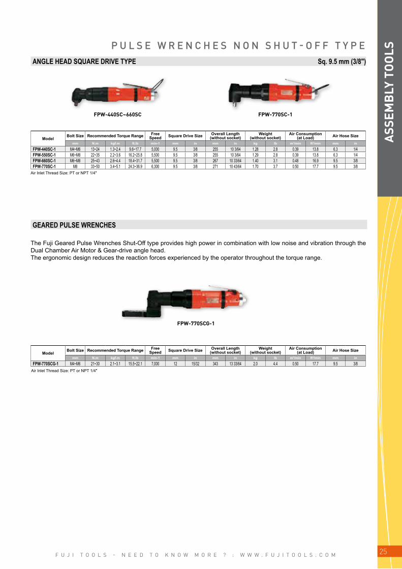
P U L S E W R E N C H E S N O N S H U T - O F F T Y P EANGLE HEAD SQUARE DRIVE TYPE Sq. 9.5 mm (3/8")
ModelBolt Size Recommended Torque Range Free
Speed Square Drive Size Overall Length (without socket)
Weight(without socket)
Air Consumption (at Load) Air Hose Size
mm N.m kgf.m ft.lb min-1 mm in mm in kg lb m3/min ft3/min mm in
FPW-440SC-1 M4~M6 13~24 1.3~2.4 9.6~17.7 5,000 9.5 3/8 255 10 3/64 1.28 2.8 0.39 13.8 6.3 1/4FPW-550SC-1 M6~M8 22~35 2.2~3.6 16.2~25.8 5,500 9.5 3/8 255 10 3/64 1.29 2.8 0.39 13.8 6.3 1/4FPW-660SC-1 M6~M8 25~43 2.6~4.4 18.4~31.7 5,500 9.5 3/8 267 10 33/64 1.40 3.1 0.48 16.9 9.5 3/8FPW-770SC-1 M8 33~50 3.4~5.1 24.3~36.9 6,300 9.5 3/8 271 10 43/64 1.70 3.7 0.50 17.7 9.5 3/8
ModelBolt Size Recommended Torque Range Free
Speed Square Drive Size Overall Length (without socket)
Weight(without socket)
Air Consumption (at Load) Air Hose Size
mm N.m kgf.m ft.lb min-1 mm in mm in kg lb m3/min ft3/min mm in
FPW-770SCG-1 M4~M6 21~30 2.1~3.1 15.5~22.1 7,000 12 15/32 343 13 33/64 2.0 4.4 0.50 17.7 9.5 3/8
GEARED PULSE WRENCHES
The Fuji Geared Pulse Wrenches Shut-Off type provides high power in combination with low noise and vibration through the Dual Chamber Air Motor & Gear-drive angle head.The ergonomic design reduces the reaction forces experienced by the operator throughout the torque range.
Air Inlet Thread Size: PT or NPT 1/4"
Air Inlet Thread Size: PT or NPT 1/4"
ASS
EMB
LY T
OO
LS

F U J I T O O L S - N E E D T O K N O W M O R E ? : W W W . F U J I T O O L S . C O M26
2
6
5
1
3
4
Plunger
Accumulator Mechanism
Environmentally Friendly Design
Ergonomic Design
Shut-off Valve
Piston Datum Return
FLT Series
P U L S E W R E N C H E S S H U T - O F F T Y P E
SHUT-OFF VALVE MECHANISM (PATENT PENDING)The New Shutoff Valve Mechanism (Patent pending) provides the benefit of Operation at Low Pressure.The new design shut off valve utilize a "total pressure" mechanism to maintain the balance of the shut off valve. The new valve design operates over a range of 0,5-0.63 MPa (5-6.3 bar, 58-90psl) air pressure.Compared to the conventional designed differential pressure valves (which require the use of a spring to maintain the balance of force against the shut off valve, and often a spring change to accomodate different air pressure levels), the "total pressure" design provides a superior efficiency operation and improve productivity levels.
PLUNGER MECHANISM (PATENT PENDING)Plunger Mechanism (Patent pending) provides the benefit of improved Torque Accuracy.For control of low torque, the oil pressure applied to the piston is maintained at a low level and improves torque control. To ensure high accuracy control of low torque, the plunger mechanism is utilised to deliver troque accurately. Oil leakage is prevented within the mechanism via a passage in the plunger which is designed to accommodate changes in oil pressure when the pulse is generated. Consequently, torque and tightening accuracy stability are maintained.
PISTON DATUM RETURN MECHANISM (PATENT PENDING)Torque control is influenced by the movement of the piston as oil pressure changes during pulse generation. The operation of the shut off valve ensures the mechanism for returning the piston to datum position is activated after detecting the change in oil pressure.The next tightening operation can be applied quickly and fastening torque scatter is improved due to this behaviour of the piston.
ACCUMULATOR MECHANISMThe Accumulator functions to compensate against the sudden rise of oil pressure when tightening a hard joint. Torque scatter and error is minimised.As the oil temperature increases during consecutive tightening, the accumulator takes in the ex-panded volume of oil to maintain a consistent oil volume in the pulse unit. This ensures high tightening torque accuracy.
ENVIRONMENT FRIENDLY DESIGNTo reduce effects on the environment and environmental energy during the life cycle of the tool, no paint is applied to the body of the tool. Consequently, the effect of paint peeling is eliminated. The full cover protector is designed as standard.
ERGONOMIC DESIGNCompared with conventionnal tools, weight is kept to a minimum. The grip handle size is optimised to provide enhanced levels of operator comfort. This special grip also absorbs vibration more effectively. Furthermor, reduced noise and vibration levels are standard with the FLT series due to the optimised dimensions.
1
2
3
4
5
6
F E A T U R E S
ASS
EMB
LY T
OO
LS
F U J I T O O L S - N E E D T O K N O W M O R E ? : W W W . F U J I T O O L S . C O M 27
FLT-20S-1
FLT-9-1 FLT-4D-1FLT-4-1
FLT-4S-1
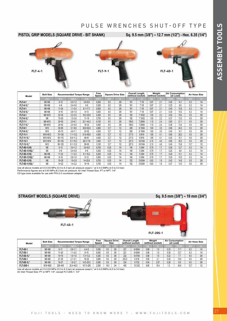
P U L S E W R E N C H E S S H U T - O F F T Y P EPISTOL GRIP MODELS (SQUARE DRIVE - BIT SHANK) Sq. 9.5 mm (3/8") ~ 12.7 mm (1/2") - Hex. 6.35 (1/4")
ModelBolt Size Recommended Torque Range Free
SpeedSquare Drive
SizeOverall Length
(without socket)Weight
(without socket)Air Consumption
(at Load) Air Hose Size
mm N.m kgf.m ft.lb min-1 mm in mm in kg lb m3/min ft3/min mm in
FLT-4S-1 M5~M6 6~11 0.6~1.1 4.4~8 5,500 9.5 3/8 221 8 45/64 0.88 1.9 0.33 11.7 6.3 1/4FLT-5S-1 M6~M8 11~20 1.1~2.0 8~15 6,400 9.5 3/8 221 8 45/64 0.88 1.9 0.36 12.7 6.3 1/4FLT-5S-1L* M6~M8 10~18 1.0~1.8 7.3~13.2 5,300 9.5 3/8 222 8 47/64 0.88 1.9 0.22 7.7 9.5 3/8FLT-6S-1 M6~M8 21~30 2.1~3.1 16~22 5,800 9.5 3/8 233.5 9 3/16 0.95 2.1 0.45 15.9 9.5 3/8FLT-6S-1L* M6~M8 19~27 1.9~2.7 14.5~20.5 5,000 9.5 3/8 234 9 7/32 0.94 2.07 0.28 9.9 9.5 3/8FLT-20S-1 M18~M20 200~400 20.4~40.8 147.5~295 2,500 19.0 3/4 405 15 3/32 8.80 19.4 1.3 45.8 12.7 1/2
Use all above models at 0.5-0.63 MPa (5.0 to 6.3 bar) air pressure exept L* at 0.4-0.5MPa (4.0 to 5.0 bar) Performance figures are at 0.63 MPa (6.3 bar) air pressure. Air Inlet Thread Size: PT or NPT: 1/4". CD type tools available for use with FFA-2-2 countdown adapter
STRAIGHT MODELS (SQUARE DRIVE) Sq. 9.5 mm (3/8") ~ 19 mm (3/4")
Use all above models at 0.5-0.63 MPa (5.0 to 6.3 bar) air pressure exept L* at 0.4-0.5MPa (4.0 to 5.0 bar)Air Inlet Thread Size: PT or NPT: 1/4", except FLT-20S-1: 1/2"
ASS
EMB
LY T
OO
LS
ModelBolt Size Recommended Torque Range Free
Speed Square Drive Size Overall Length (without socket)
Weight(without socket)
Air Consumption (at Load) Air Hose Size
mm N.m kgf.m ft.lb min-1 mm in mm in kg lb m3/min ft3/min mm in
FLT-4-1 M5~M6 5~12 0.5~1.2 3.6~8.8 6,200 9.5 3/8 181 7 1/8 0.97 2.1 0.40 14.1 6.3 1/4FLT-4-1L* M5~M6 4~8 0.4~0.8 3~6 5,300 9.5 3/8 181 7 1/8 0.97 2.1 0.25 8.8 6.3 1/4FLT-5-1 M6~M8 11~24 1.1~2.4 8.1~17.7 6,500 9.5 3/8 181 7 1/8 0.97 2.1 0.45 15.8 6.3 1/4FLT-5-1L* M6~M8 8~18 0.8~1.8 6~13 5,500 9.5 3/8 181 7 1/8 0.97 2.1 0.30 10.5 6.3 1/4FLT-6-1 M8~M10 22~35 2.2~3.5 16.2~25.8 6,300 9.5 3/8 192 7 19/32 1.00 2.2 0.55 19.4 9.5 3/8FLT-6-1L* M8 15~26 1.5~2.6 11~19 5,700 9.5 3/8 192 7 19/32 1.00 2.2 0.37 13.0 9.5 3/8FLT-7-1 M8~M10 30~55 3.0~6.1 22.1~44.2 6,100 9.5 3/8 189.5 7 29/64 1.10 2.4 0.60 21.1 9.5 3/8FLT-7-1L* M8~M10 24~45 2.4~4.6 18~33 5,400 9.5 3/8 189.5 7 29/64 1.10 2.4 0.38 13.4 9.5 3/8FLT-9-1 M10 50~85 5.1~8.6 36.8~62.6 4,800 12.7 1/2 209 8 15/64 1.60 3.5 0.68 24.0 9.5 3/8FLT-9-1L* M10 45~70 4.6~7.1 33~52 4,500 12.7 1/2 209 8 15/64 1.60 3.5 0.40 14.1 9.5 3/8FLT-11-1 M10~M12 70~120 7.1~13.2 51.6~95.8 4,500 12.7 1/2 217.5 8 9/16 1.85 4.1 0.80 28.2 9.5 3/8FLT-11-1L* M10~M12 65~110 6.6~11.2 48~81 4,400 12.7 1/2 217.5 8 9/16 1.85 4.1 0.43 15.1 9.5 3/8FLT-13-1 M12~M14 90~155 9.1~16.3 66.3~118 3,400 12.7 1/2 227.5 8 61/64 2.10 4.6 0.85 30.0 9.5 3/8FLT-13-1L* M12 80~125 8.1~12.5 59~93 3,100 12.7 1/2 227.5 8 61/64 2.10 4.6 0.45 15.8 12.7 1/2FLT-4D-1(10) M6 5~12 0.5~1.2 3.6~8.8 6,700 6.35 1/4 140 5 3/64 0.79 1.7 0.36 12.7 6.3 1/4FLT-4D-1(10)L* M5 5~8 0.4~0.8 4~6 5,300 6.35 1/4 140 5 3/64 0.79 1.7 0.25 8.8 6.3 1/4FLT-5D-1(10) M6~M8 11~22 1.1~2.2 8.1~16.2 6,300 6.35 1/4 140 5 3/64 0.79 1.7 0.40 14.1 6.3 1/4FLT-5D-1(10)L* M6~M8 8~16 0.8~1.6 6~12 5,500 6.35 1/4 140 5 3/64 0.79 1.7 0.30 10.5 6.3 1/4FLT-6D-1(10) M8 19~28 1.9~2.8 14~20.6 6,700 6.35 1/4 152 5 63/64 0.83 1.8 0.42 14.8 9.5 3/8FLT-6D-1(10)L* M8 14~22 1.4~2.2 10~16 5,700 6.35 1/4 152 5 63/64 0.83 1.8 0.37 13.0 9.5 3/8

F U J I T O O L S - N E E D T O K N O W M O R E ? : W W W . F U J I T O O L S . C O M28
FPT-110D-1 FPT-1660-1
FPT-110S-1FPT-770S
FLT-4SD-1
A
B
P U L S E W R E N C H E S S H U T - O F F T Y P E
PISTOL GRIP MODELS (SQUARE DRIVE - BIT SHANK) Hex. 6.35 mm (1/4") ~ Sq. 9.5 mm (3/8") ~ 19 mm (3/4")
ModelBolt Size Recommended Torque Range Free
SpeedSquare Drive Size
Bit Shank SizeOverall Length
(without socket)Weight
(without socket)Air Consumption
(at Load) Air Hose Size
mm N.m kgf.m ft.lb min-1 mm in mm in kg lb m3/min ft3/min mm in
FPT-110-1 M5~M6 4~7 0.4~0.7 3.0~5.2 6,000 9.5 3/8 194.5 7 21/32 0.95 2.1 0.20 7.1 6.3 1/4FPT-110D-1(10) M5~M6 4~7 0.4~0.7 3.0~5.2 6,000 6.35 1/4 197.5 7 25/32 0.95 2.1 0.20 7.1 6.3 1/4FPT-1660-1 M16~M18 150~210 15.3~21.4 110.6~154.9 2,800 19.0 3/4 266 10 31/64 4.4 9.7 1.2 42.4 9.5 3/8
Air Inlet Thread Size: PT or NPT1/4" except FPT-1660-1: 3/8"
STRAIGHT MODELS (SQUARE DRIVE) Sq. 9.5 mm (3/8")
ModelBolt Size Recommended Torque Range Free
SpeedSquare Drive
SizeOverall Length
(without socket)Weight
(without socket)Air Consumption
(at Load) Air Hose Size
mm N.m kgf.m ft.lb min-1 mm in mm in kg lb m3/min ft3/min mm in
FPT-110S-1 M4~M5 4~7 0.4~0.7 3.0~5.2 4,500 9.5 3/8 236.5 9 5/16 0.85 1.9 0.20 7.1 6.3 1/4FPT-330S-1 M5~M6 6~10 0.6~1.0 4.4~7.4 4,400 9.5 3/8 249 9 13/16 1.1 2.4 0.35 12.3 6.3 1/4FPT-770S-1 M8~M10 30~45 3.1~4.6 22.1~33.2 5,500 9.5 3/8 273.5 10 49/64 1.6 3.5 0.45 15.9 9.5 3/8
Air Inlet Thread Size: PT or NPT 1/4"
ASS
EMB
LY T
OO
LS
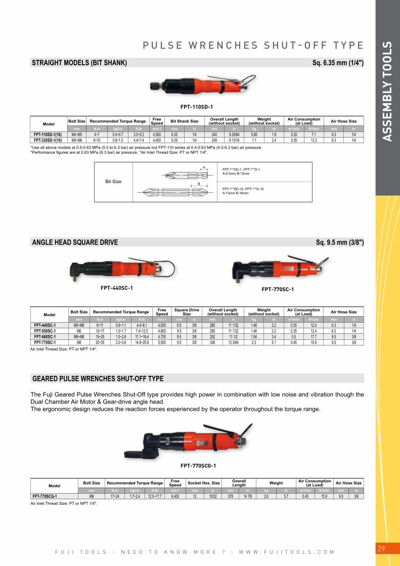
STRAIGHT MODELS (BIT SHANK) Hex. 6.35 mm (1/4")
ModelBolt Size Recommended Torque Range Free
Speed Bit Shank Size Overall Length (without socket)
Weight(without socket)
Air Consumption (at Load) Air Hose Size
mm N.m kgf.m ft.lb min-1 mm in mm in kg lb m3/min ft3/min mm in
FLT-4SD-1(10) M5~M6 5.5~11 0.5~1.1 3.8~8.4 4,300 6.35 1/4 222 8 47/64 0.88 1.94 0.33 11.6 6.3 1/4FLT-5SD-1(10) M6~M8 11~20 1.1~2.0 8.3~15.2 6,400 6.35 1/4 222 8 47/64 0.88 1.94 0.36 12.7 6.3 1/4FLT-5SD-1(10)L* M6~M8 10~18 1.0~1.8 7.6~13.7 5,300 6.35 1/4 222 8 47/64 0.88 1.94 0.22 7.7 6.3 1/4FLT-6SD-1(10) M8 21~30 2.1~3.0 22.8~13.7 5,800 6.35 1/4 234 9 7/32 0.94 2.07 0.42 14.8 9.5 3/8FLT-6SD-1(10)L* M6~M8 19~27 1.9~2.7 14.4~20 5,000 6.35 1/4 234 9 7/32 0.94 2.07 0.28 9.9 9.5 3/8
Use all above models at 0.5-0.63 MPa (5.0 to 6.3 bar) air pressure exept L* at 0.4-0.5MPa (4.0 to 5.0)Air Inlet Thread Size: PT or NPT 1/4"
Bit Size
FLT-***SD-1, FLT-***D-1A:9.5mm B:12mm
FLT-***SD-10, FLT-***D-10A:13mm B:16mm
F U J I T O O L S - N E E D T O K N O W M O R E ? : W W W . F U J I T O O L S . C O M 29
FPT-110SD-1
FPT-440SC-1 FPT-770SC-1
FPT-770SCG-1
A
B
ModelBolt Size Recommended Torque Range Free
Speed Bit Shank Size Overall Length (without socket)
Weight(without socket)
Air Consumption (at Load) Air Hose Size
mm N.m kgf.m ft.lb min-1 mm in mm in kg lb m3/min ft3/min mm in
FPT-110SD-1(10) M4~M5 4~7 0.4~0.7 3.0~5.2 4,500 6.35 1/4 240 9 29/64 0.85 1.9 0.20 7.1 6.3 1/4FPT-330SD-1(10) M5~M6 6~10 0.6~1.0 4.4~7.4 4,400 6.35 1/4 249 9 13/16 1.1 2.4 0.35 12.3 6.3 1/4
ModelBolt Size Recommended Torque Range Free
SpeedSquare Drive
SizeOverall Length
(without socket)Weight
(without socket)Air Consumption
(at Load) Air Hose Size
mm N.m kgf.m ft.lb min-1 mm in mm in kg lb m3/min ft3/min mm in
FPT-440SC-1 M5~M6 6~11 0.6~1.1 4.4~8.1 4,500 9.5 3/8 280 11 1/32 1.46 3.2 0.35 12.4 6.3 1/4FPT-550SC-1 M6 10~17 1.0~1.7 7.4~12.5 4,800 9.5 3/8 280 11 1/32 1.46 3.2 0.35 12.4 6.3 1/4FPT-660SC-1 M6~M8 15~25 1.5~2.6 11.1~18.4 4,700 9.5 3/8 292 11 1/2 1.54 3.4 0.5 17.7 9.5 3/8FPT-770SC-1 M8 20~35 2.0~3.6 14.8~25.8 5,500 9.5 3/8 306 12 3/64 2.3 5.1 0.45 15.9 9.5 3/8
*Use all above models at 0.5-0.63 MPa (5.0 to 6.3 bar) air pressure but FPT-110 series at 0.4-0.63 MPa (4.0-6.3 bar) air pressure. *Performance figures are at 0.63 MPa (6.3 bar) air pressure. *Air Inlet Thread Size: PT or NPT 1/4".
Air Inlet Thread Size: PT or NPT 1/4".
P U L S E W R E N C H E S S H U T - O F F T Y P E
Air Inlet Thread Size: PT or NPT 1/4".
The Fuji Geared Pulse Wrenches Shut-Off type provides high power in combination with low noise and vibration though the Dual Chamber Air Motor & Gear-drive angle head.The ergonomic design reduces the reaction forces experienced by the operator throughout the torque range.
ModelBolt Size Recommended Torque Range Free
Speed Socket Hex. Size Overall Length Weight Air Consumption
(at Load) Air Hose Size
mm N.m kgf.m ft.lb min-1 mm in mm in kg lb m3/min ft3/min mm in
FPT-770SCG-1 M6 17~24 1.7~2.4 12.5~17.7 6,400 12 15/32 378 14 7/8 2.6 5.7 0.45 15.9 9.5 3/8
STRAIGHT MODELS (BIT SHANK) Sq. 6.35 mm (1/4")
ANGLE HEAD SQUARE DRIVE Sq. 9.5 mm (3/8")
GEARED PULSE WRENCHES SHUT-OFF TYPE A
SSEM
BLY
TO
OLS
Bit Size
FPT-***SD-1, FPT-***D-1A:9.5mm B:12mm
FPT-***SD-10, FPT-***D-10A:13mm B:16mm

F U J I T O O L S - N E E D T O K N O W M O R E ? : W W W . F U J I T O O L S . C O M30
FW-44PA~66PA FW-88P-1
FW-44SA~66SA
I M P A C T W R E N C H E SFuji Impact Wrenches FW-44~88 have 9-blade dual chamber motor and double clutch type impact mechanism.They are designed for giving high torque at low speed, which give the best characteristics for fast reliable and accurate tighte-ning. These models are provided with two types of lubricant in clutch part, FW-44PA~66PA and FW-44SA~66SA series are with oil (Oil Bath type) which features long service life and FW-44P~88P and FW-44S~66S are with conventional grease.Both series are suitable for self tapping type soft joint.
PISTOL GRIP MODELS Sq. 9.5 mm (3/8”) ~ 12.7 mm (1/2”)
STRAIGHT MODEL Sq. 9.5 mm (3/8”)
ModelBolt Size
Recommended Torque Range
Max Torque
Free Speed Square Drive Size Overall Length
(without socket)Weight
(without socket)Air Consumption
(at Load) Air Hose Size
mm N.m kgf.m ft.lb N.m min-1 mm in mm in kg lb m3/min ft3/min mm in
•FW-44PA-2 M5 8~16 0.8~1.6 5.9~11.8 20 6,500 9.5 3/8 131 5 5/32 0.78 1.7 0.60 21.2 6.3 1/4•FW-66PA-2 M6 14~26 1.4~2.7 10.3~19.2 32 5,000 9.5 3/8 137 5 25/64 0.88 1.9 0.48 16.9 6.3 1/4FW-88P-1 M8 27~50 2.8~5.1 19.9~36.9 70 5,300 12.7 1/2 163 6 27/64 1.40 3.1 0.64 22.5 9.5 3/8
ModelBolt Size Recommended Torque Range Max
TorqueFree
Speed Square Drive Size Overall Length (without socket)
Weight(without socket)
Air Consumption (at Load) Air Hose Size
mm N.m kgf.m ft.lb N.m min-1 mm in mm in kg lb m3/min ft3/min mm in
•FW-44SA-1 M5 8~16 0.8~1.6 5.9~11.8 20 5,700 9.5 3/8 207 8 5/32 0.66 1.4 0.35 12.4 6.3 1/4•FW-66SA-1 M6 14~26 1.4~2.7 10.3~19.2 32 5,000 9.5 3/8 212 8 11/32 0.78 1.7 0.37 13.1 6.3 1/4
*Marked • are oil bath types. *All Models are double clutch types.*Air Inlet Thread Size: PT or NPT 1/4".
*Marked • are oil bath types. *All Models are double clutch types.*Air Inlet Thread Size: PT or NPT 1/4".
ASS
EMB
LY T
OO
LS

F U J I T O O L S - N E E D T O K N O W M O R E ? : W W W . F U J I T O O L S . C O M 31
FW-5PX-6
FW-6PX-5~6
FW-14PH-1~2
FW-14PH-3
FW-6PM-1
FW-6PH-1~11
FW-10PH-1~2
FW-6PL-1
FW-8PH-3
FW-14PX-5
I M P A C T W R E N C H E SFuji Impact Wrenches are suitable for various fastening and unfastening operations. The combination of high torque and fast run down minimise operator fatigue.
PISTOL GRIP MODELS Sq. 9.5 mm (3/8") ~ 12.7 mm (1/2") ~ 15.9 mm (5/8")
ModelBolt Size Recommended Torque Range Max
TorqueFree
Speed Square Drive Size Overall Length (without socket)
Weight(without socket)
Air Consumption (at Load) Air Hose Size
mm N.m kgf.m ft.lb N.m min-1 mm in mm in kg lb m3/min ft3/min mm in
•FW-5PX-6 M5 8~13 0.8~1.3 5.9~9.6 18 12,000 9.5 3/8 150 5 29/32 0.80 1.8 0.20 7.1 6.3 1/4•FW-6PM-1 M6 14~26 1.4~2.7 10.3~19.2 32 8,500 9.5 3/8 140 5 33/64 0.92 2.0 0.53 18.7 9.5 3/8•FW-6PL-1 M6 14~26 1.4~2.7 10.3~19.2 32 10,000 9.5 3/8 175 6 57/64 0.90 2.0 0.20 7.1 9.5 3/8•FW-6PX-5 M6 11~23 1.1~2.3 8.1~17.0 30 10,000 9.5 3/8 156 6 9/64 1.20 2.6 0.28 9.9 9.5 3/8•FW-6PX-6 M6 10~18 1.0~1.8 7.4~13.3 25 10,000 9.5 3/8 156 6 9/64 1.20 2.6 0.28 9.9 9.5 3/8•FW-6PH-1 M8 27~40 2.8~4.1 19.9~29.5 60 9,000 9.5 3/8 147 5 25/32 1.35 3.0 0.35 12.4 9.5 3/8•FW-6PH-11 M8 27~40 2.8~4.1 19.9~29.5 60 9,000 12.7 1/2 152 6 1.40 3.1 0.35 12.4 9.5 3/8•FW-8PH-3 M10 42~80 4.3~8.2 31.0~59.0 130 7,500 12.7 1/2 162 6 3/8 1.50 3.3 0.40 14.1 9.5 3/8•FW-10PH-1 M10 63~120 6.4~12.2 46.5~88.5 160 7,500 12.7 1/2 179 7 3/64 2.00 4.4 0.45 15.8 9.5 3/8•FW-10PH-2 M10 47~93 4.8~9.5 34.7~68.6 113 7,500 12.7 1/2 179 7 3/64 2.00 4.4 0.45 15.8 9.5 3/8•FW-14PX-5 M14 100~150 10.2~15.3 73.8~110.6 190 6,500 12.7 1/2 197 7 3/4 3.00 6.6 0.40 14.1 9.5 3/8•FW-14PH-1 M14 85~140 8.7~14.3 62.7~103.3 180 7,500 12.7 1/2 202 7 15/16 2.56 5.7 0.60 21.2 9.5 3/8•FW-14PH-2 M14 85~140 8.7~14.3 62.7~103.3 180 7,500 12.7 1/2 202 7 15/16 2.56 5.7 0.60 21.2 9.5 3/8•FW-14PH-3 M14 85~140 8.7~14.3 62.7~103.3 180 7,500 15.9 5/8 202 7 15/16 2.56 5.7 0.60 21.2 9.5 3/8
*Marked • are oil bath types. *All Models are double clutch types.*Air Inlet Thread Size: PT or NPT 1/4".
ASS
EMB
LY T
OO
LS

F U J I T O O L S - N E E D T O K N O W M O R E ? : W W W . F U J I T O O L S . C O M32
CA-14A + FW-14SX-5CA-14A
FW-6SX-5~6
FW-10SX-5
FW-6SCX-6
FW-8SH-2
FW-14SX-5
FW-8SCH-2
ACCESSORIES
CORNER ATTACHMENT (ANGLE HEAD)
ModelBolt Size Recommended Torque Range Max
TorqueFree
Speed Square Drive Size Overall Length (without socket)
Weight(without socket)
Air Consumption (at Load) Air Hose Size
mm N.m kgf.m ft.lb N.m min-1 mm in mm in kg lb m3/min ft3/min mm in
FW-6SX-5 M6 11~23 1.1~2.3 8.1~17.0 30 10,000 9.5 3/8 223 8 25/32 1.10 2.4 0.30 10.6 9.5 3/8•FW-6SX-6 M6 10~18 1.0~1.8 7.4~13.3 25 10,000 9.5 3/8 223 8 25/32 1.10 2.4 0.30 10.6 9.5 3/8•FW-8SH-2 M10 35~67 3.6~6.8 25.8~49.4 93 8,000 12.7 1/2 306 12 3/64 1.70 3.7 0.40 14.1 9.5 3/8•FW-10SX-5 M10 50~100 5.1~10.2 36.9~73.8 150 8,000 12.7 1/2 317 12 31/64 2.20 4.8 0.40 14.1 9.5 3/8•FW-14SX-5 M14 100~150 10.2~15.3 73.8~110.6 190 6,500 12.7 1/2 356 14 1/64 3.00 6.6 0.50 17.7 9.5 3/8
ModelBolt Size Recommended Torque Range Max
TorqueFree
Speed Square Drive Size Overall Length (without socket)
Weight(without socket)
Air Consumption (at Load) Air Hose Size
mm N.m kgf.m ft.lb N.m min-1 mm in mm in kg lb m3/min ft3/min mm in
•FW-6SCX-6 M6 9~18 0.9~1.8 6.6~13.3 20 8,000 9.5 3/8 261 10 9/32 1.60 3.5 0.30 10.5 9.5 3/8•FW-8SCH-2 M10 33~67 3.4~6.8 24.3~49.4 87 7,500 12.7 1/2 347 13 21/32 2.70 5.9 0.40 14.1 9.5 3/8
*Marked • are oil bath types. *All Models are double clutch types.*Air Inlet Thread Size: PT or NPT 1/4".
The Corner Attachment CA-14A can be mounted on straight or pistol grip type impact wrenches FW-14PX, 14SX to access fastening in confined spaces.
IMPACT WRENCHES + CORNER ATTACHMENT
ModelSide to Center Square Drive Size Angle Head Height Overall Length Weight
(without socket) Modelsmm in mm in mm in mm in kg lb
CA-14A 24.5 31/32 12.7 1/2 84 3 5/16 146 5 3/4 1.4 3.0 FW-14PX,14SX Series
I M P A C T W R E N C H E SSMALL SIZE STRAIGHT MODELS Sq. 9.5 mm (3/8") ~ 12.7 mm (1/2")
ANGLE HEAD MODELS Sq. 9.5 mm (3/8") ~ 12.7 mm (1/2")
Air Inlet Thread Size: PT or NPT 1/4".
ASS
EMB
LY T
OO
LS

F U J I T O O L S - N E E D T O K N O W M O R E ? : W W W . F U J I T O O L S . C O M 33
FW-19Z-5
FW-320-1
FW-250-1~2
FW-420-1C~2C
MEDIUM SIZE STRAIGHT MODELS Sq. 19 mm (3/4") ~ 25.4 mm (1") ~ 31.8 mm (1 1/4")
ModelBolt Size
Recommended Torque Range
Max Torque
Free Speed Square Drive Size Overall Length
(without socket)Weight
(without socket)Air Consumption
(at Load) Air Hose Size
mm N.m kgf.m ft.lb N.m min-1 mm in mm in kg lb m3/min ft3/min mm in
FW-19Z-5 18 235~450 24.0~45.9 174-333 560 5,000 19.0 3/4 322.0 12 43/64 5.20 0.60 0.6 21.2 9.5 3/8"•FW-19Z-5C 18 235~450 24.0~45.9 174-333 560 5,000 19.0 3/4 322.0 12 43/64 5.20 0.60 0.6 21.2 9.5 3/8"FW-250-1 24 380~1,040 38.8~106.1 281-720 1,200 5,000 25.4 1 302.0 11 57/64 6.00 0.70 0.7 24.7 12.7 1/2"FW-250-1C 24 380~1,040 38.8~106.1 281-720 1,200 5,000 25.4 1 302.0 11 57/64 6.00 0.70 0.7 24.7 12.7 1/2"FW-250-2 24 380~1,040 38.8~106.1 281-720 1,200 5,000 19.0 3/4 302.0 11 57/64 6.00 0.70 0.7 24.7 12.7 1/2"FW-250-2C 24 380~1,040 38.8~106.1 281-720 1,200 5,000 19.0 3/4 302.0 11 57/64 6.00 0.70 0.7 24.7 12.7 1/2"FW-320-1 30~33 600~1,800 61.2~183.6 444-1333 2,300 4,800 25.4 1 353.0 13 29/32 8.70 1.00 1.0 35.3 12.7 1/2"FW-320-1C 30~33 600~1,800 61.2~183.6 444-1333 2,300 4,800 25.4 1 353.0 13 29/32 8.70 1.00 1.0 35.3 12.7 1/2"FW-320-1L 30~33 600~1,800 61.2~183.6 444-1333 2,300 4,800 25.4 1 484.0 19 1/16 10.00 1.00 1.0 35.3 12.7 1/2"FW-320-1CL 30~33 600~1,800 61.2~183.6 444-1333 2,300 4,800 25.4 1 484.0 19 1/16 10.00 1.00 1.0 35.3 12.7 1/2"•FW-420-1 36~42 900~2,500 91.8~255.0 666-1852 2,800 4,500 25.4 1 349.0 13 3/7 10.80 1.20 1.2 42.4 19.0 3/4"•FW-420-1C 36~42 900~2,500 91.8~255.0 666-1852 2,800 4,500 25.4 1 349.0 13 3/7 10.80 1.20 1.2 42.4 19.0 3/4"•FW-420-1L 36~42 900~2,500 91.8~255.0 666-1852 2,800 4,500 25.4 1 501.0 19 3/4 12.50 1.20 1.2 42.4 19.0 3/4"•FW-420-1CL 36~42 900~2,500 91.8~255.0 666-1852 2,800 4,500 25.4 1 501.0 19 3/4 12.50 1.20 1.2 42.4 19.0 3/4"•FW-420-2 36~42 900~2,500 91.8~255.0 666-1852 2,800 4,500 31.8 1 1/4 351.0 13,81887 10.80 1.20 1.2 42.4 19.0 3/4"•FW-420-2C 36~42 900~2,500 91.8~255.0 666-1852 2,800 4,500 31.8 1 1/4 351.0 13,81887 10.80 1.20 1.2 42.4 19.0 3/4"
*Marked • are long anvil types. *Models with C are Inside Lever types.*FW-19Z-5 is single clutch type. Other Models are 2-Jaw clutch types.
I M P A C T W R E N C H E S
*Air Inlet Thread Size: PT 1/2" except FW-19Z-5/-5C : 3/8"
FW-320-1CL (Long Anvil Type) Inside Lever type
FW-420-1L (Long Anvil Type)
Outside Lever typeFW-420-1CL
Inside Lever type
ASS
EMB
LY T
OO
LS
F U J I T O O L S - N E E D T O K N O W M O R E ? : W W W . F U J I T O O L S . C O M34
FW-19PX-5 FW-250P-1~2 FW-320P-1
FW-50-7FW-100-1
MEDIUM SIZE STRAIGHT MODELS Sq. 19 mm (3/4") ~ 25.4 mm (1")
ModelBolt Size Recommended Torque Range Max
TorqueFree
Speed Square Drive Size Overall Length (without socket)
Weight(without socket)
Air Consumption (at Load) Air Hose Size
mm N.m kgf.m ft.lb N.m min-1 mm in mm in kg lb m3/min ft3/min mm in
•FW-19PX-5 M18 235~450 24.0~45.9 173.3~331.9 560 5,000 19.0 3/4 239 9 13/32 4.4 9.7 0.6 21.2 9.5 3/8•FW-250P-1 M24 380~1040 38.8~106.1 280.3~767.0 1200 5,000 25.4 1 228 8 31/32 5.3 11.7 0.7 24.7 12.7 1/2•FW-250P-2 M24 380~1040 38.8~106.1 280.3~767.0 1200 5,000 19.0 3/4 228 8 31/32 5.3 11.7 0.7 24.7 12.7 1/2•FW-320P-1 M30~M33 600~1800 61.2~183.6 442.5~1327.5 2300 4,800 25.4 1 268 10 36/64 8.0 17.6 1.0 35.3 12.7 1/2
ModelBolt Size Recommended Torque Range Max
TorqueFree
Speed Square Drive Size Overall Length (without socket)
Weight(without socket)
Air Consumption (at Load) Air Hose Size
mm N.m kgf.m ft.lb N.m min-1 mm in mm in kg lb m3/min ft3/min mm in
•FW-50-7 M50 3300~7050 336.6~719.1 2433.8~5199.4 8400 4,000 38.1 1 1/2 500 19 11/16 33.0 72.6 1.9 67.3 19.0 3/4•FW-75-7 M68 5100~12400 520.2~1264.8 3761.3~9145.0 14000 3,000 63.5 2 1/2 610 24 1/64 60.0 132.0 2.1 74.9 19.0 3/4•FW-100-1 M76 9250~20800 943.5~2121.6 6821.9~15340.0 22000 2,500 63.5 2 1/2 700 27 9/16 85.0 188.7 3.2 114.1 25.4 1
*FW-19PX-5 is single clutch type. Other Models are 2-Jaw clutch types.
All Models are double clutch types.
HIGH TORQUE SUPER HEAVY DUTY MODELS Sq. 38.1 mm (1 1/2") ~ 63.5 mm (2 1/2")
I M P A C T W R E N C H E S
*Air Inlet Thread Size: PT or NPT 3/8" except FW-19PX-5 1/4".
Air Inlet Thread Size: PT or NPT 1".
ASS
EMB
LY T
OO
LS

F U J I T O O L S - N E E D T O K N O W M O R E ? : W W W . F U J I T O O L S . C O M 35
A
B
FW-5SXD-7(70) FW-5SXD-8(80) FW-6SXD-6(60)
FW-5PXD-6(60)
FW-6PHD-1 FW-6PMD-1(10)
FW-6PLD-1 FW-6PXD-6(60)
FW-*SXD-6, 7, 8, *PXD-6, *PLD-1, *PHD-1 A: 9.5 mm B: 12 mm
FW-*SXD-60, 70, 80, *PXD-60, *PMD-10 A: 13 mm B: 16 mm
Air Inlet Thread Size: PT or NPT 1/4".
Air Inlet Thread Size: PT or NPT 1/4".
Fuji screwdrivers are suitable for a wide range of screw fastening and disassembly applications.The compact and lightweight design provides operator comfort. All models are reversible via a reverse lever or push button. Impact clutch type models are all of double clutch design and their high torque and fast run-down minimise operator fatigue. Slip clutch type models are suitable for sheet metal screws andthe torque setting can be adjusted easily.
IMPACT CLUTCH TYPE - STRAIGHT MODELS Hex. 6.35 mm (1/4")
PISTOL GRIP MODELS Hex. 6.35 mm (1/4")
ModelBolt Size Recommended Torque Range Max
TorqueFree
Speed Bit Shank Size Overall Length (without socket)
Weight(without socket)
Air Consumption (at Load) Air Hose Size
mm N.m kgf.m ft.lb N.m min-1 mm in mm in kg lb m3/min ft3/min mm in
FW-5SXD-7 M5 6~11 0.6~1.1 4.4~8.1 20 12,000 6.35 1/4 223 8 25/32 0.70 1.5 0.20 7.1 6.3 1/4FW-5SXD-70 M5 6~11 0.6~1.1 4.4~8.1 20 12,000 6.35 1/4 223 8 25/32 0.70 1.5 0.20 7.1 6.3 1/4FW-5SXD-8 M5 6~11 0.6~1.1 4.4~8.1 20 12,000 6.35 1/4 193 7 19/32 0.65 1.4 0.20 7.1 6.3 1/4FW-5SXD-80 M5 6~11 0.6~1.1 4.4~8.1 20 12,000 6.35 1/4 193 7 19/32 0.65 1.4 0.20 7.1 6.3 1/4FW-6SXD-6 M6 10~18 1.0~1.8 7.4~13.3 25 10,000 6.35 1/4 235 9 1/4 1.10 2.4 0.30 10.6 9.5 3/8FW-6SXD-60 M6 10~18 1.0~1.8 7.4~13.3 25 10,000 6.35 1/4 235 9 1/4 1.10 2.4 0.30 10.6 9.5 3/8
ModelBolt Size Recommended Torque Range Max
TorqueFree
Speed Bit Shank Size Overall Length (without socket)
Weight(without socket)
Air Consumption (at Load) Air Hose Size
mm N.m kgf.m ft.lb N.m min-1 mm in mm in kg lb m3/min ft3/min mm in
FW-5PXD-6 M5 6~11 0.6~1.1 4.4~8.1 20 12,000 6.35 1/4 160 6 19/64 0.80 1.8 0.30 10.6 6.3 1/4FW-5PXD-60 M5 6~11 0.6~1.1 4.4~8.1 20 12,000 6.35 1/4 160 6 19/64 0.80 1.8 0.30 10.6 6.3 1/4FW-6PMD-1 M6 11~22 1.1~2.2 8.1~16.2 34 12,000 6.35 1/4 160 6 19/64 0.80 1.8 0.30 10.6 6.3 1/4FW-6PMD-10 M6 11~22 1.1~2.2 8.1~16.2 34 8,500 6.35 1/4 146 5 3/4 0.92 2.0 0.53 18.7 9.5 3/8FW-6PLD-1 M6 11~22 1.1~2.2 8.1~16.2 34 10,000 6.35 1/4 182 7 11/64 0.90 2.0 0.20 7.1 9.5 3/8FW-6PXD-6 M6 10~18 1.0~1.8 7.4~13.3 25 10,000 6.35 1/4 168 6 5/8 1.20 2.6 0.28 9.9 9.5 3/8FW-6PXD-60 M6 10~18 1.0~1.8 7.4~13.3 25 10,000 6.35 1/4 168 6 5/8 1.20 2.6 0.28 9.9 9.5 3/8FW-6PHD-1 M8 19~40 1.9~4.1 14.0~29.5 60 9,000 6.35 1/4 154 6 1/6 1.35 3.0 0.35 12.4 9.5 3/8
Bit Size
S C R E W D R I V E R S
ASS
EMB
LY T
OO
LS

F U J I T O O L S - N E E D T O K N O W M O R E ? : W W W . F U J I T O O L S . C O M36
A
B
FW-44SAD~66SAD
FD-4FD-5
FD-4PFD-5P
FW-44PAD~66PAD
FW-**SAD-1, FD-4, 4P, 5, 5PFW-, **PAD-2A:9.5mm B:12mm
FW-**SAD-10FW-**PAD-20A:13mm B:16mm
IMPACT CLUTCH TYPE Hex. 6.35 mm (1/4")
ModelBolt Size Recommended Torque Range Max
TorqueFree
Speed Bit Shank Size Overall Length (without socket)
Weight(without socket)
Air Consumption (at Load) Air Hose Size
mm N.m kgf.m ft.lb N.m min-1 mm in mm in kg lb m3/min ft3/min mm inStraight Models
•FW-44SAD-1 M5 6~13 0.6~1.3 4.4~9.6 20 5,700 6.35 1/4 207 8 5/32 0.66 1.4 0.35 12.4 6.3 1/4•FW-44SAD-10 M5 6~13 0.6~1.3 4.4~9.6 20 5,700 6.35 1/4 207 8 5/32 0.66 1.4 0.35 12.4 6.3 1/4•FW-66SAD-1 M6 11~20 1.1~2.0 8.1~14.8 28 5,000 6.35 1/4 218 8 19/32 0.78 1.7 0.37 13.1 6.3 1/4•FW-66SAD-10 M6 11~20 1.1~2.0 8.1~14.8 28 5,000 6.35 1/4 218 8 19/32 0.78 1.7 0.37 13.1 6.3 1/4Pistol Grip Models
•FW-44PAD-2 M5 6~13 0.6~1.3 4.4~9.6 20 6,500 6.35 1/4 132 5 3/16 0.78 1.7 0.60 21.2 6.3 1/4•FW-44PAD-20 M5 6~13 0.6~1.3 4.4~9.6 20 6,500 6.35 1/4 132 5 3/16 0.78 1.7 0.60 21.2 6.3 1/4•FW-66PAD-2 M6 11~20 1.1~2.0 8.1~14.8 28 5,000 6.35 1/4 143 5 5/8 0.88 1.9 0.48 16.9 6.3 1/4•FW-66PAD-20 M6 11~20 1.1~2.0 8.1~14.8 28 5,000 6.35 1/4 143 5 5/8 0.88 1.9 0.48 16.9 6.3 1/4
ModelBolt Size Recommended Torque Range Free
Speed Bit Shank Size Overall Length (without socket)
Weight(without socket)
Air Consumption (at Load) Air Hose Size
mm N.m kgf.m ft.lb min-1 mm in mm in kg lb m3/min ft3/min mm inStraight Models
FD-4 M4 1~4 0.1~0.4 0.7~3.0 2,000 6.35 1/4 174 6 27/32 0.6 1.3 0.20 7.1 6.3 1/4•FD-5 M5 6~12 0.6~1.2 4.4~8.9 1,600 6.35 1/4 233 9 11/64 1.0 2.2 0.30 10.6 6.3 1/4Pistol Grip Models
FD-4P M4 1~4 0.1~0.4 0.7~3.0 2,000 6.35 1/4 173 6 13/16 0.8 1.7 0.20 7.1 6.3 1/4•FD-5P M5 6~12 0.6~1.2 4.4~8.9 1,600 6.35 1/4 216 8 1/2 1.2 2.6 0.30 10.6 6.3 1/4
SLIP CLUTCH TYPE Hex. 6.35 mm (1/4")
*Marked • are oil bath types.Air Inlet Thread Size: PT or NPT 1/4".
*Marked • are oil bath types.Air Inlet Thread Size: PT or NPT 1/4"..
Bit Size
S C R E W D R I V E R S
ASS
EMB
LY T
OO
LS

F U J I T O O L S - N E E D T O K N O W M O R E ? : W W W . F U J I T O O L S . C O M 37
FRW-6NX-3, ~4(A)
FRW-10N-2 FRW-13N-3,~4
FRW-8NX-2, ~2(A)
SOCKET SIZE
ModelSocket Hexagone Size (mm)
Standard Other Sizes
FRW-6NX-3 10 8 • 8W • 10WFRW-6NX-3A 10 8FRW-6NX-4 13 12 • 12W • 13WFRW-6NX-4A 13 12FRW-8NX-2 14 10 • 12 • 13 • 1/2" • 9/16" • 10W • 12W • 13W • 14WFRW-8NX-2A 14 10 • 12 • 13FRW-10N-2 17 13 • 14 • 16 • 9/16" • 5/8" • 14W • 17WFRW-13N-3 21 18 • 19 • 19W • 21WFRW-13N-4 24 22 • 26 • 27 • 22W • 24W • 26W • 27W
*Specify the socket size in ordering the tool.
Air Inlet Thread Size: PT or NPT 1/4".NX models have silencer
ModelBolt Size Max Torque Free
SpeedHex.
Socket Size
Head Size Overall Length Weight Air Consumption
(at Load) Air Hose SizeThickness Width Lengthmm N.m kgf.m ft.lb min-1 mm mm in mm in mm in mm in kg lb m3/min ft3/min mm in
FRW-6NX-3 M6 10.8 1.1 8.1 200 10 13 33/64 20 25/32 88 3 15/32 316 12 7/16 1.2 2.6 0.25 8.8 9.5 3/8FRW-6NX-3A M6 10.8 1.1 8.1 200 10 10 25/64 20 25/32 88 3 15/32 316 12 7/16 1.2 2.6 0.25 8.8 9.5 3/8FRW-6NX-4 M6 12.7 1.3 9.4 170 13 13 33/64 24 61/64 93 3 21/32 320 12 9/16 1.2 2.6 0.25 8.8 9.5 3/8FRW-6NX-4A M6 12.7 1.3 9.4 170 13 10 25/64 24 61/64 93 3 21/32 320 12 9/16 1.2 2.6 0.25 8.8 9.5 3/8FRW-8NX-2 M8 29.4 3.0 22.1 200 14 18 45/64 25 63/64 108 4 1/4 378 14 57/64 2.2 4.9 0.43 15.2 9.5 3/8FRW-8NX-2A M8 29.4 3.0 22.1 200 14 10 25/64 25 63/64 108 4 1/4 378 14 57/64 2.1 4.6 0.43 15.2 9.5 3/8FRW-10N-2 M10 44.1 4.5 33.1 140 17 18 45/64 33 1 19/64 115 4 17/32 417 16 13/32 2.7 6.0 0.58 20.5 9.5 3/8FRW-13N-3 M12 58.8 6.0 44.1 130 21 18 45/64 36 1 27/64 116 4 9/16 419 16 1/2 2.7 6.0 0.58 20.5 9.5 3/8FRW-13N-4 M12 78.4 8.0 58.8 100 24 18 45/64 46 1 13/64 129 4 5/64 431 16 31/32 3.0 6.6 0.58 20.5 9.5 3/8
Ratchet Wrenches are used for fastening operations in confined spaces where angle impact tools and nutrunners cannot reach. Reverse operation can be accomplished by simply turning the wrench over.
R A T C H E T W R E N C H E S
HEAD SIZESocket Hex. Size
Length
Width
Thickness
ASS
EMB
LY T
OO
LS
F U J I T O O L S - N E E D T O K N O W M O R E ? : W W W . F U J I T O O L S . C O M38
SSQ
BHex
L
SS
Q
SS
Q
L
D
SS
Q
SS
QD
L
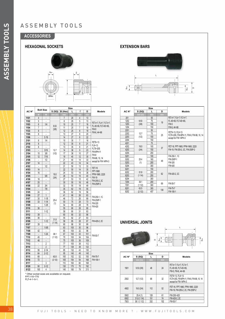
HEXAGONAL SOCKETS EXTENSION BARS
UNIVERSAL JOINTS
AC N°Bolt Size
SizeModelsS (SQ) B (Hex) L D
M W mm (in) mm mm mm mm
1101 4 -
9.53(3/8)
7 20 4 13
FET-4~7, FL4~7, FLT-4~7, FL 4S~6S, FLT-4S~6S,FW-5FW-6, 44~66
1102 5 - 8 25 5 131103 6 1/4 10 25 7 161104 7 - 11 25 7 181133 8 - 12 25 8 191105 8 - 13 27 8 201106 - 5 /16 14 27 8 222101 6 1/4
12.7(1/2)
10 35 7 18 FET9~13 FL9~13FLT9~20S FW-6PH-11FW-8FW-88, 10, 14except for FW-14PH-3
2118 8 - 12 35 8 212102 8 - 13 35 8 212103 - 5/16 14 38 9 232104 10 3/8 17 38 10 272105 12 7/16 19 40 12 302106 - 1/2 21 40 14 332107 14 - 22 43 14 344102 - 1/2
19.0(3/4)
21 50 13 33 FET-16 FPT-1660FPW-1660, 2220FW-19FW-250-2, 2CFW-250P-2
4103 14 - 22 50 14 354104 16 - 24 53 14 384105 - 5/8 26 53 15 404106 18 - 27 53 15 424107 20 - 30 55 16 464108 22 3/4 32 55 18 495104 - 7/8
25.4(1)
35 62 19 55
FW-250-1, 1CFW-250P-1FW-320FW-420
5105 24 - 36 62 19 565106 27 1 41 68 26 635107 30 1-1/8 46 72 26 695108 33 1-1/4 50 75 28 735109 - 1-3/8 54 80 28 785110 36 - 55 80 28 805111 - 1-1/2 58 80 31 835112 39 - 60 80 32 866105 36 - 31.8
(1 1/4)
55 82 27 83FW-420-2, 2C6106 - 1-1/2 58 85 28 87
6107 39 - 60 88 30 897107 - 1-5/8
38.1(1 1/2)
63 100 30 96
FW-50-7
7108 42 - 65 100 32 987109 - 1-3/4 67 100 33 1017110 45 - 70 100 34 1047112 48 - 75 105 36 1097113 - 2 77 105 38 1128110 - 2
63.5(2 1/2)
77 128 38 122
FW-75-7FW-100-1
8112 56 2-1/4 85 132 43 1308114 64 2-1/2 95 140 49 1458115 68 - 100 152 52 1508116 72 - 105 154 54 1688117 - 3 110 160 60 1688120 90 3-1/2 130 170 70 1928122 100 4 145 180 79 213
AC N°Size
ModelsS (SQ) L Dmm (in) mm mm
2019.53(3/8)
50
19
FET-4~7, FL4~7, FLT-4~7, FL 4S~6S, FLT-4S~6S,FW-5FW-6, 44~66
1202 751203 1001204 1502201
12.7(1/2)
50
25FET9~13, FL9~13FLT9~20S, FW-6PH-11, FW-8, FW-88, 10, 14except for FW-14PH-3
2202 752203 1002204 1504201
19.0(3/4)
75
37 FET-16, FPT-1660, FPW-1660, 2220FW-19, FW-250-2, 2C, FW-250P-2
4202 1004203 1504204 2005201
25.4(1)
100
49
FW-250-1, 1CFW-250P-1FW-320FW-420
5202 1605203 2005204 3006201
31.8(1 1/4)
150
62 FW-420-2, 2C6202 2006203 2506204 3007204 38.1
(1 1/2)200 69 FW-50-77201 300
8201 63.5(2 1/2)
300 130 FW-75-7FW-100-18202 457
AC N°Size
ModelsS (SQ) L Dmm (in) mm mm
1501 9.53 (3/8) 48 24FET-4~7, FL4~7, FLT-4~7, FL 4S~6S, FLT-4S~6S,FW-5, FW-6, 44~66
2502 12.7 (1/2) 68 32FET9~13, FL9~13FLT9~20S, FW-6PH-11, FW-8, FW-88, 10, 14 except for FW-14PH-3
4502 19.0 (3/4) 112 52 FET-16, FPT-1660, FPW-1660, 2220FW-19, FW-250-2, 2C, FW-250P-2
5502 25.4 (1) 128 61 FW-250~4206502 31.8 (1 1/4) 151 74 FW-420-2, 2C7503 38.1 (1 1/2) 202 102 FW-50-7
* Other socket sizes are available on request.FPT-110~770FLT-4-1~5-1.
A S S E M B L Y T O O L S
ACCESSORIES
ASS
EMB
LY T
OO
LS
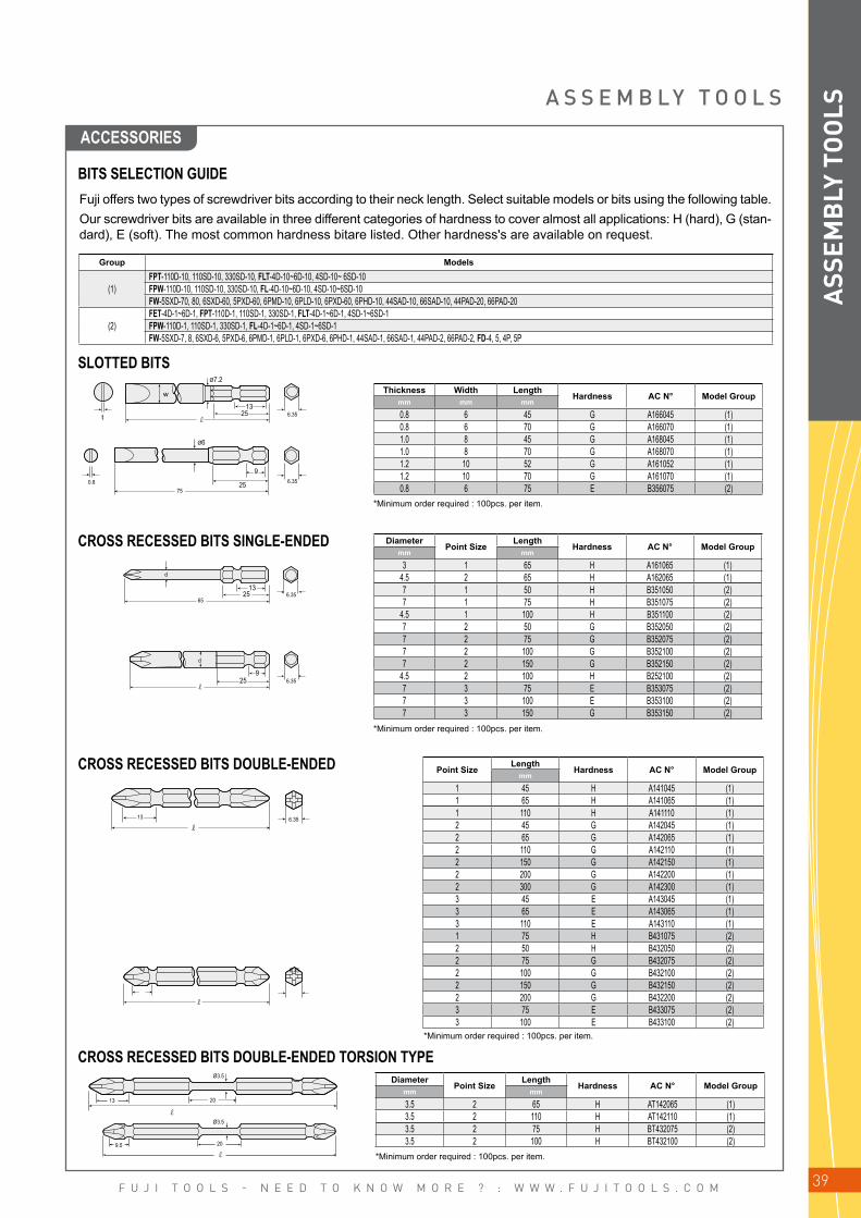
F U J I T O O L S - N E E D T O K N O W M O R E ? : W W W . F U J I T O O L S . C O M 39
t
w
25
25
25
25
13
9
13
9
Ø7.2
Ø6
0.8
d
d
75
65
13
13
13
9.5
6.35
6.35
6.35
6.35
6.35
6.35
20
20
Ø3.5
Ø3.5
SLOTTED BITS
CROSS RECESSED BITS SINGLE-ENDED
CROSS RECESSED BITS DOUBLE-ENDED
CROSS RECESSED BITS DOUBLE-ENDED TORSION TYPE
Thickness Width LengthHardness AC N° Model Group
mm mm mm
0.8 6 45 G A166045 (1)0.8 6 70 G A166070 (1)1.0 8 45 G A168045 (1)1.0 8 70 G A168070 (1)1.2 10 52 G A161052 (1)1.2 10 70 G A161070 (1)0.8 6 75 E B356075 (2)
*Minimum order required : 100pcs. per item.
*Minimum order required : 100pcs. per item.
*Minimum order required : 100pcs. per item.
DiameterPoint Size
LengthHardness AC N° Model Group
mm mm
3 1 65 H A161065 (1)4.5 2 65 H A162065 (1)7 1 50 H B351050 (2)7 1 75 H B351075 (2)
4.5 1 100 H B351100 (2)7 2 50 G B352050 (2)7 2 75 G B352075 (2)7 2 100 G B352100 (2)7 2 150 G B352150 (2)
4.5 2 100 H B252100 (2)7 3 75 E B353075 (2)7 3 100 E B353100 (2)7 3 150 G B353150 (2)
DiameterPoint Size
LengthHardness AC N° Model Group
mm mm
3.5 2 65 H AT142065 (1)3.5 2 110 H AT142110 (1)3.5 2 75 H BT432075 (2)3.5 2 100 H BT432100 (2)
Point SizeLength
Hardness AC N° Model Groupmm
1 45 H A141045 (1)1 65 H A141065 (1)1 110 H A141110 (1)2 45 G A142045 (1)2 65 G A142065 (1)2 110 G A142110 (1)2 150 G A142150 (1)2 200 G A142200 (1)2 300 G A142300 (1)3 45 E A143045 (1)3 65 E A143065 (1)3 110 E A143110 (1)1 75 H B431075 (2)2 50 H B432050 (2)2 75 G B432075 (2)2 100 G B432100 (2)2 150 G B432150 (2)2 200 G B432200 (2)3 75 E B433075 (2)3 100 E B433100 (2)
*Minimum order required : 100pcs. per item.
Group Models
(1)FPT-110D-10, 110SD-10, 330SD-10, FLT-4D-10~6D-10, 4SD-10~ 6SD-10 FPW-110D-10, 110SD-10, 330SD-10, FL-4D-10~6D-10, 4SD-10~6SD-10 FW-5SXD-70, 80, 6SXD-60, 5PXD-60, 6PMD-10, 6PLD-10, 6PXD-60, 6PHD-10, 44SAD-10, 66SAD-10, 44PAD-20, 66PAD-20
(2)FET-4D-1~6D-1, FPT-110D-1, 110SD-1, 330SD-1, FLT-4D-1~6D-1, 4SD-1~6SD-1FPW-110D-1, 110SD-1, 330SD-1, FL-4D-1~6D-1, 4SD-1~6SD-1FW-5SXD-7, 8, 6SXD-6, 5PXD-6, 6PMD-1, 6PLD-1, 6PXD-6, 6PHD-1, 44SAD-1, 66SAD-1, 44PAD-2, 66PAD-2, FD-4, 5, 4P, 5P
Fuji offers two types of screwdriver bits according to their neck length. Select suitable models or bits using the following table.Our screwdriver bits are available in three different categories of hardness to cover almost all applications: H (hard), G (stan-dard), E (soft). The most common hardness bitare listed. Other hardness's are available on request.
BITS SELECTION GUIDE
A S S E M B L Y T O O L S
ACCESSORIES
ASS
EMB
LY T
OO
LS

F U J I T O O L S - N E E D T O K N O W M O R E ? : W W W . F U J I T O O L S . C O M40
H2-2.5-3-4-5-6
H2-2.5-3-4-5-6
13
9
25
d
d
13
6.35
6.35
25
Ø7
6.35
6.35
25
9
A S S E M B L Y T O O L S
ALLEN BITS
TORX® BITS
Point SizeLength
Hardness AC N° Model Groupmm
2 65 H A16H2065 (1)2 110 H A16H2110 (1)
2.5 65 H A16H25065 (1)2.5 110 H A16H25110 (1)3 65 H A16H3065 (1)3 110 H A16H3110 (1)4 65 H A16H4065 (1)4 110 H A16H4110 (1)5 65 G A16H5065 (1)5 110 G A16H5110 (1)6 65 G A16H6065 (1)6 110 G A16H6110 (1)2 75 H B35H2075 (2)2 100 H B35H2100 (2)
2.5 75 H B35H25075 (2)2.5 100 H B35H25100 (2)3 75 H B35H3075 (2)3 100 H B35H3100 (2)4 75 H B35H4075 (2)4 100 H B35H4100 (2)5 75 G B35H5075 (2)5 100 G B35H5100 (2)6 75 G B35H6075 (2)6 100 G B35H6100 (2)
Point SizeLength Body Diameter
AC N° Model Groupmm mm
T6 65 4.0 VT6065 (1)T8 65 4.5 VT8065 (1)T8 110 4.5 VT8110 (1)T10 65 4.5 VT10065 (1)T10 110 4.5 VT10110 (1)T15 65 4.5 VT15065 (1)T15 110 4.5 VT15110 (1)T20 65 5.0 VT20065 (1)T20 110 5.0 VT20110 (1)T25 65 5.0 VT25065 (1)T25 110 5.0 VT25110 (1)T27 65 5.5 VT27065 (1)T27 110 5.5 VT27110 (1)T30 65 6.0 VT30065 (1)T30 110 6.0 VT30110 (1)T40 65 H6.35 VT40065 (1)T40 110 H6.35 VT40110 (1)T6 75 4.0 JT6075 (2)T6 100 4.0 JT6100 (2)T8 75 4.5 JT8075 (2)T8 100 4.5 JT8100 (2)T10 75 4.5 JT10075 (2)T10 100 4.5 JT10100 (2)T15 75 4.5 JT15075 (2)T15 100 4.5 JT15100 (2)T20 75 5.0 JT20075 (2)T20 100 5.0 JT20100 (2)T25 75 5.0 JT25075 (2)T25 100 5.0 JT25100 (2)T27 75 5.5 JT27075 (2)T27 100 5.5 JT27100 (2)T30 75 6.0 JT30075 (2)T30 100 6.0 JT30100 (2)T40 75 7.0 JT40075 (2)T40 100 7.0 JT40100 (2)T45 75 8.0 JT45075 (2)T45 100 8.0 JT45100 (2)
ACCESSORIES
ASS
EMB
LY T
OO
LS
*Minimum order required : 100pcs. per item.
*Minimum order required : 100pcs. per item.

F U J I T O O L S - N E E D T O K N O W M O R E ? : W W W . F U J I T O O L S . C O M 41
H4.5-5-5.5-6
20
25
25
33
20
33100
100
55
55
13
13
13
13
Ø7.2
DØ
DØ
DØ
DØ
Ø7.2
Ø7.2
Ø7.2
Ø7.2
Ø7.2
23
25
25
23
H5.5-6-7
H8-10-13
H7-8-9-9.6-10-11 12-13-14-15-17
H5.5-6-7
H8-10-12-13-14
6.35
6.35
6.35
6.35
6.35
6.35
25
25
33
33
9
9
DØ
DØ
25
25
BHEX L
S(S
Q)
BHEX
D
S(S
Q)
L
Double-ended bit
Chuck
ALLEN SOCKETS
A S S E M B L Y T O O L S
SOCKET HEAD BITS
*Minimum order required : 100pcs. /item.
Point SizeLength Body Diameter
AC N° Model Groupmm mm
4.5 55 7.5 A2045055 (1)5 55 8.5 A205055 (1)
5.5 55 10 A2055055 (1)5.5 100 10 A2055100 (1)6 55 10 A206055 (1)6 100 10 A206100 (1)7 55 13 A207055 (1)7 100 13 A207100 (1)8 55 13 A208055 (1)8 100 13 A208100 (1)9 55 16 A209055 (1)10 55 16 A2010055 (1)10 100 16 A2010100 (1)11 55 16 A2011055 (1)12 55 19 A2012055 (1)12 100 19 A2012100 (1)13 55 19 A2013055 (1)13 100 19 A2013100 (1)14 55 20 A2014055 (1)15 55 22 A2015055 (1)17 55 23 A2017055 (1)5.5 75 10 B4555075 (2)5.5 100 10 B4555100 (2)6 100 10 B456100 (2)7 75 13 B457075 (2)7 100 13 B457100 (2)8 75 13 B458075 (2)8 100 13 B458100 (2)8 150 13 B458150 (2)10 75 16 B4510075 (2)10 100 16 B4510100 (2)10 150 16 B4510150 (2)12 100 18 B4512100 (2)13 75 19 B4513075 (2)13 100 19 B4513100 (2)14 100 20 B4514100 (2)
AC N°Size
ModelsS (SQ) B(Hex) L Dmm (in) mm mm mm mm
HG-3-4
9.53(3/8)
4 50 15 19 FPT-110~770FLT-4-1~9-1FL-4-1~9-1
FPW-110~770FW-5,
FW-6, 44~66
HG-3-5 5 50 17 19HG-3-6 6 50 18 19HG-3-8 8 60 23 20HG-3-10 10 60 27 20HG-4-6
12.7(1/2)
6 60 18 25 FLT-11-1~20S-1FL-11-1~13-1
FW-6PH-11, 8, 88FW-10, 14 except
for FW-14PH-3
HG-4-8 8 60 23 25HG-4-10 10 68 27 27HG-4-12 12 68 30 27HG-4-14 14 78 40 28
CHUCKS FOR WRENCHES FOR USE OF BITS TOOL COVER FOR FPW SERIES
AC N°Size
ModelsS (SQ) B (Hex) Lmm (in) mm (in) mm
DC-1 9.53 (3/8) 6.35 (1/4) 51 FPT-110, FLT-4-1~9-1FPW-110, FL-4-1~9-1, FW-5, 6, 44~66
DC-2 12.7(1/4) 8.00 (5/16) 56 FLT-11-1~20S-1 - FL11-1~13-1FW-6PH-11, 8, 88, 10, 14 except for FW-14PH-3
AC N° ModelsTCV-1 FL-5-1~6-1TCV-2 FL-7-1
ACCESSORIES
ASS
EMB
LY T
OO
LS

F U J I T O O L S - N E E D T O K N O W M O R E ? : W W W . F U J I T O O L S . C O M42
N O T E S
ASS
EMB
LY T
OO
LS

F U J I T O O L S - N E E D T O K N O W M O R E ? : W W W . F U J I T O O L S . C O M 43
ABRASIVE TOOLS
INSTRUCTION AND WARNING FOR SAFETY USE _________ 44
ABRASIVE TOOLS FEATURES ___________________________________________ 45
PENCIL & TURBO GRINDERS __________________________________________ 46
DIE GRINDERS ___________________________________________________________________ 47
DIE GRINDERS FOR MOUNTED POINT ___________________________ 49
LOW-SPEED & STRAIGHT GRINDERS ____________________________ 50
EXTENDED GRINDERS _____________________________________________________ 53
ANGLE GRINDERS / SMALL TO LARGE _________________________ 55
ANGLE SANDERS _____________________________________________________________ 57
VERTICAL SANDERS _________________________________________________________ 59
BELT SANDERS _________________________________________________________________ 60
ORBITAL SANDERS ___________________________________________________________ 61
ACCESSORIES ___________________________________________________________________ 62

F U J I T O O L S - N E E D T O K N O W M O R E ? : W W W . F U J I T O O L S . C O M44
I N S T R U C T I O N A N D W A R N I N G F O R S A F E T Y U S E
GRINDERS AND SANDERS
INTENDED USEThe tool is designed to be used with abrasive product for grinding, cutting and sanding materials. Do not use the tool for any other purpose.
PROTECTIVE EQUIPMENTAlways wear necessary protective equipment such as an eye protector, an ear protector, a face shield, a safety apron, a helmet, gloves and other necessary protective clothing. Use protective barriers where necessary
MAXIMUM SPEEDS OF ABRASIVE PRODUCT AND TOOLAlways check the spindle speed of the tool when mounting the abrasive product. Ensure that the maximum free speed rating of the abrasive product is above that of the tool in use.
WHEEL SIZES OF ABRASIVE PRODUCT AND PERIPHERAL SPEEDThe following is a reference of Grinding wheel size / Peripheral speed / Maximum free speed. When using abrasive product, on which the peripheral speed is shown instead of the maximum allowable free speed, refer to the reference.
CORRECT WHEEL GUARD AND FLANGES FOR GRINDERAlways use the wheel guard and wheel flanges supplied with the tool and ensure that they are mounted correctly with the appropriate tightness when mounting the abrasive product. Only trained & qualified personnel should mount the abrasive product. Do not use a wheel guard or the flanges if they are damaged or worn. Do not modify or repair a wheel guard or flanges.
CORRECT ABRASIVE PRODUCT TO CORRECT TOOLMake sure the dimensions of the abrasive product are compatible with the tool and that the abrasive product fits the spindle of the tool.
MOUNTING AND DISMOUNTING ABRASIVE PRODUCTWhen mounting and dismounting the abrasive product, make sure to disconnect tool. Make sure the dimensions of the abrasive product are compatible with the tool and that the abrasive product fits the spindle of the tool.
TOOL WITH SPEED GOVERNORFor the grinder with a speed governor, check the maximum free speed regularly.Make it a rule to check the maximum free speed, whenever before use.
Wheel diameter - Peripheral speed - Maximum free speedGrinding
Wheel diameter
Peripheral Speed (m/s)10 15 20 25 28 30 33 35 40 45 48 50 60 70 80
mm Maximum free speed (min-1)
25 7639 11459 15279 19099 21390 22918 25210 26738 30558 34377 36669 38197 45837 53476 6111540 4775 7162 9549 11937 13369 14324 15756 16711 19099 21486 22918 23873 28648 33423 3819750 3820 5730 7639 9549 10695 11459 12605 13369 15279 17189 18335 19099 22918 26738 3055863 3032 4547 6063 7579 8488 9095 10004 10610 12126 13642 14551 15158 18189 21221 2425280 2387 3581 4775 5968 6685 7162 7878 8356 9549 10743 11459 11937 14324 16711 19099100 1910 2865 3820 4775 5348 5730 6303 6685 7639 8594 9167 9549 11459 13369 15279115 1661 2491 3321 4152 4650 4982 5480 5813 6643 7473 7972 8304 9964 11625 13286125 1528 2292 3056 3820 4278 4584 5042 5348 6112 6875 7334 7639 9167 10695 12223150 1273 1910 2546 3183 3565 3820 4202 4456 5093 5730 6112 6366 7639 8913 10186180 1061 1592 2122 2653 2971 3183 3501 3714 4244 4775 5093 5305 6366 7427 8488200 955 1432 1910 2387 2674 2865 3151 3342 3820 4297 4584 4775 5730 6685 7639230 830 1246 1661 2076 2325 2491 2740 2906 3321 3737 3986 4152 4982 5813 6643250 764 1146 1528 1910 2139 2292 2521 2674 3056 3438 3667 3820 4584 5348 6112300 637 955 1273 1592 1783 1910 2101 2228 2546 2865 3056 3183 3820 4456 5093
AB
RA
SIVE
TO
OLS

F U J I T O O L S - N E E D T O K N O W M O R E ? : W W W . F U J I T O O L S . C O M 45
A B R A S I V E T O O L S F E A T U R E SREAR EXHAUST
CENTRIFUGAL SPEED GOVERNOR
ANTI-FREEZING SWIVEL SILENCER
GEAR COOLING DEVICE
LOCKING LEVER HANDLE
ACCURATE COLLET ALIGNMENT
STURDY STEEL HOUSING
The rear exhaust reduces the risk of scattering debris such as grindings, shavings, etc. due to the exhaust air direction. In addition, when using the inlet and exhaust hoses supplied with the tools, this helps to reduce the sound level.
The speed governor maintains the working speed of the tool to a better degree than a conventional tool without a governor. Consequently, the abrasive life is improved due to the stability of the cutting speed. It is less susceptible to changes in air pressure and wear of the governor parts.ANGLE, STRAIGHT, VERTICAL GRINDERS
The anti-freezing swivel silencer minimises the effect of freezing during operation of the tool. In addition, it also enables the operator to direct the exhaust air to provide maximum operator comfort.ANGLE GRINDERS EXCEPT FA-2C, 3CX, 150K SERIES
The patented gear cooling device helps to minimise wearing of the bevel gear and pinion by metering some exhaust air through them and providing a cooling effect.ANGLE GRINDERS
The locking lever helps to reduce the risk of inadvertent starting of the tool. The operator needs to push the locking lever, or the locking button, to start operation of the tool. When the lever is released, the tool automatically reverts to the locked condition.
The collet is mounted in the spindle in order to provide mini-mal deflection.Furthermore, the compact collet nut enables finishing opera-tions in confined spaces.
Die Grinders feature a compact and durable steel housing for longer service life.
AB
RA
SIVE
TO
OLS

F U J I T O O L S - N E E D T O K N O W M O R E ? : W W W . F U J I T O O L S . C O M46
FG-06-1
FG-06-S-1
TURBO-100 TURBO-100A
AB
RA
SIVE
TO
OLS
Air Inlet Thread Size: PT or NPT 1/4"
Air Inlet Thread Size: PT or NPT 1/8"
P E N C I L G R I N D E R / T U R B O G R I N D E R S
Pencil Grinders are excellent tools for deburring, contouring and light grinding when used with a rotary burr. The small compact diameter, and light weight, aid precise application.
ModelCollet Size
Max. Dia. Free Speed Power Overall
Length Weight Max. Air Consumption Air Hose SizeMounted Wheel Burr Head
mm in mm in mm in min-1 W hp mm in kg lb m3/min ft3/min mm in
FG-06-1 3 1/8 10 3/8 6 1/4 60,000 100 0.14 153 6 1/32 0.2 0.4 0.17 6.0 4.0 5/32FG-06-S-1 3 1/8 10 3/8 6 1/4 60,000 107 0.15 166 6 17/32 0.13 0.28 0.17 6.0 4.0 5/32
ModelCollet Size
Max. Dia.Free Speed Power Overall
Length Weight Max. Air Consumption Air Hose SizeMounted Wheel Burr Head
mm in mm in mm in min-1 W hp mm in kg lb m3/min ft3/min mm in
TURBO-100 3 - 8 5/16 6 1/4 80,000~100,000 50 0.07 153 6 1/32 0.2 0.4 0.28 9.8 4.0 5/32TURBO-100A 6 1/4 8 5/16 8 5/16 80,000~100,000 50 0.07 155 6 7/64 0.2 0.4 0.28 9.8 4.0 5/32
TURBO GRINDERSSuper high speed operation provides a more precise finish. Ø3mm or Ø1/8" and Ø6mm or Ø1/4" collet sizes are available to suit the application.
Accessories Provided for Turbo Series
F-101 Open-End Wrench (1) F-301 Hex Wrench (1) IH-4B Inlet Hose (1) AL3000-1/4 Oiler (1) F-501 Pin Wrench (1) BB-SF0011 Ball Bearing (2)
PENCIL GRINDER

F U J I T O O L S - N E E D T O K N O W M O R E ? : W W W . F U J I T O O L S . C O M 47
FG-13-2
FG-13X-2
FG-13-1
FG-13X-1F
FG-13-10
FG-13X-10F
FG-13-20
FG-13X-20
13 mm
AB
RA
SIVE
TO
OLS
ROLL THROTTLE MODELS
LEVER HANDLE MODELS (NOT AVAILABLE FOR CE AND ANSI/NA MARKETS)
LOCKING LEVER HANDLE MODELS
ModelCollet Size
Max. Dia. Free Speed Power Overall
Length Weight Max. Air Consumption Air Hose SizeMounted Wheel Burr Head
mm in mm in mm in min-1 W hp mm in kg lb m3/min ft3/min mm in
Front Exhaust Type FG-13-2 3 1/8 13 1/2 10 3/8 30,000 150 0.21 150 5 29/32 0.3 0.3 2.5 8.8 6.3 1/4FG-13-20 3 1/8 13 1/2 10 3/8 30,000 150 0.21 150 5 29/32 0.4 0.9 2.5 8.8 6.3 1/4Rear Exhaust TypeFG-13X-2 3 - 13 1/2 10 3/8 30,000 130 0.17 179 7 3/64 0.4 0.9 0.21 7.4 6.3 1/4FG-13X-20 3 1/8 13 1/2 10 3/8 30,000 130 0.17 179 7 3/64 0.4 0.9 0.21 7.4 6.3 1/4
ModelCollet Size
Max. Dia. Free Speed Power Overall
Length Weight Max. Air Consumption Air Hose SizeMounted Wheel Burr Head
mm in mm in mm in min-1 W hp mm in kg lb m3/min ft3/min mm in
Front Exhaust Type FG-13-1 3 1/8 13 1/2 10 3/8 30,000 150 0.21 158 6 7/32 0.3 0.3 2.5 8.8 6.3 1/4FG-13-10 3 - 13 1/2 10 3/8 30,000 150 0.21 158 6 7/32 0.4 0.9 2.5 8.8 6.3 1/4Rear Exhaust TypeFG-13X-1 3 1/8 13 1/2 10 3/8 30,000 150 0.17 183 7 13/64 0.4 0.9 0.21 7.4 6.3 1/4FG-13X-10 3 - 13 1/2 10 3/8 30,000 150 0.17 183 7 13/64 0.4 0.9 0.21 7.4 6.3 1/4
ModelCollet Size
Max. Dia. Free Speed Power Overall
Length Weight Max. Air Consumption Air Hose SizeMounted Wheel Burr Head
mm in mm in mm in min-1 W hp mm in kg lb m3/min ft3/min mm in
Front Exhaust Type FG-13-1F 3 1/8 13 1/2 10 3/8 30,000 150 0.21 158 67/32 0,3 0,3 2,5 8,8 6,3 1/4FG-13-10F 3 1/8 13 1/2 10 3/8 30,000 150 0.21 158 67/32 0,4 0,9 2,5 8,8 6,3 1/4Rear Exhaust TypeFG-13X-1F 3 1/8 13 1/2 10 3/8 30,000 130 0.17 183 7 13/64 0,4 0,9 0,21 7,4 6,3 1/4FG-13X-10F 3 - 13 1/2 10 3/8 30,000 130 0.17 183 7 13/64 0,4 0,9 0,21 7,4 6,3 1/4
Air Inlet Thread Size: PT or NPT 1/4"
Air Inlet Thread Size: PT or NPT 1/4"
Air Inlet Thread Size: PT or NPT 1/4"
REAR EXHAUST MODEL (WITH HOSE)
COLLET CHUCK FOR U, D, UX, DX MODEL
DIAMETER AND OVERHANG
n Great accuracy n Strong fastening n Great durability
Please use correct diameter of burrs for the speed. Available speed is limitted by diameter and overhang of burrs applied.We show the maximum diameter in the table with overhang 13 mm.
Collet
Collet nut Spindle
D I E G R I N D E R S

F U J I T O O L S - N E E D T O K N O W M O R E ? : W W W . F U J I T O O L S . C O M48
FG-25D-2
FG-50K-1FG-25DX-2
FG-12U-1 FG-12UX-1 FG-25D-1
FG-25D-1F FG-25DX-1F
FG-12U-2
AB
RA
SIVE
TO
OLS D I E G R I N D E R S
ROLL THROTTLE MODELS (NOT AVAILABLE FOR CE AND ANSI/NA MARKETS)
LEVER HANDLE MODELS (NOT AVAILABLE FOR CE AND ANSI/NA MARKETS)
F G - 1 2 U S E R I E S , F G - 2 5 D S E R I E S A N D F G - 5 0 D S E R I E S D I E G R I N D E R
ModelCollet Size
Max. Dia. Free Speed Power Overall
Length Weight Max. Air Consumption Air Hose SizeMounted Wheel Burr Head
mm in mm in mm in min-1 W hp mm in kg lb m3/min ft3/min mm in
Side Exhaust TypeFG-12U-2 3 , 6 1/4 13 1/2 8 5/16 43,000 130 0.18 190 7 31/64 0.6 1.3 0.30 10.6 6.3 1/4FG-25D-2 3 , 6 - 25 1 13 1/2 24,000 250 0.34 202 7 61/64 0.8 1.8 0.40 14.1 9.5 3/8FG-50D-2 6 1/4 32 1 1/4 22 7/8 18,000 340 0.46 213 8 25/64 0.9 2.0 0.45 15.9 9.5 3/8FG-50K-1 6 - 20 20 7/8 19,000 320 0.43 236 9 19/64 0.8 1.8 0.42 15.9 9.5 3/8Rear Exhaust TypeFG-12UX-2 3 , 6 1/4 13 1/2 8 5/16 43,000 130 0.18 211 8 5/16 0.6 1.3 0.30 10.6 6.3 1/4FG-25DX-2 6 - 25 1 13 1/2 24,000 250 0.34 227 8 15/16 0.7 1.8 0.40 14.1 9.5 3/8FG-50DX-2 6 - 32 1 1/4 22 7/8 18,000 340 0.46 237 9 21/64 0.9 2.0 0.45 15.9 9.5 3/8
Air Inlet Thread Size: PT or NPT 1/4"
ModelCollet Size
Max. Dia. Free Speed Power Overall
Length Weight Max. Air Consumption Air Hose SizeMounted Wheel Burr Head
mm in mm in mm in min-1 W hp mm in kg lb m3/min ft3/min mm in
Front Exhaust TypeFG-12U-1 3 , 6 - 13 1/2 8 5/16 43,000 130 0.18 188 7 13/32 0.6 1.3 0.30 10.6 6.3 1/4FG-25D-1 6 1/4 25 1 13 1/2 24,000 250 0.34 198 7 51/64 0.7 1.8 0.40 14.1 9.5 3/8FG-50D-1 6 1/4 32 1 1/4 22 7/8 18,000 340 0.46 210 7 17/64 0.9 2.0 0.45 15.9 9.5 3/8Rear Exhaust TypeFG-12UX-1 3 , 6 1/4 13 1/2 8 5/16 43,000 130 0.18 213 8 25/64 0.7 1.5 0.30 10.6 6.3 1/4FG-25DX-1 3 , 6 1/4 25 1 13 1/2 24,000 250 0.34 230 9 1/16 0.8 1.8 0.40 14.1 9.5 3/8FG-50DX-1 6 1/4 32 1 1/4 22 7/8 18,000 340 0.46 243 9 9/16 0.9 2.0 0.45 15.9 9.5 3/8
Air Inlet Thread Size: PT or NPT 1/4"
LOCKING LEVER HANDLE MODELS
ModelCollet Size
Max. Dia. Free Speed Power Overall
Length Weight Max. Air Consumption Air Hose SizeMounted Wheel Burr Head
mm in mm in mm in min-1 W hp mm in kg lb m3/min ft3/min mm in
Front Exhaust TypeFG-12U-1F 3 , 6 - 13 1/2 8 5/16 43,000 130 0.18 188 7 13/32 0,6 1,3 0,30 10,6 6,3 1/4FG-25D-1F 6 1/4 25 1 13 1/2 24,000 250 0.34 198 7 51/64 0,7 1,8 0,40 14,1 9,5 3/8FG-50D-1F 6 1/4 32 1 1/4 22 7/8 18,000 340 0.46 210 7 17/64 0,9 2,0 0,45 15,9 9,5 3/8Rear Exhaust TypeFG-12UX-1F 6 1/4 13 1/2 8 5/16 43,000 130 0.18 213 8 25/64 0,7 1,5 0,30 10,6 6,3 1/4FG-25DX-1F 6 1/4 25 1 13 1/2 24,000 250 0.34 230 91/16 0,8 1,8 0,40 14,1 9,5 3/8FG-50DX-1F 6 1/4 32 1 1/4 22 7/8 18,000 340 0.46 243 99/16 0,9 2,0 0,45 15,9 9,5 3/8
Air Inlet Thread Size: PT or NPT 1/4"

F U J I T O O L S - N E E D T O K N O W M O R E ? : W W W . F U J I T O O L S . C O M 49
FG-26H-2
FG-26H-1
FG-25T
FG-50-25
FG-26HX-2 FG-50H-2 FG-50HX-2
FG-26HX-1 FG-50H-1 FG-50HX-1
FG-26HX-1F FG-50HX-1F
Ø 3 Ø6
13 mm
AB
RA
SIVE
TO
OLSD I E G R I N D E R S F O R M O U N T E D P O I N T
ROLL THROTTLE MODELS (NOT AVAILABLE FOR CE AND ANSI/NA MARKETS)
LEVER HANDLE MODELS (NOT AVAILABLE FOR CE AND ANSI/NA MARKETS)
ModelCollet Size
Max. Dia. Free Speed Power Overall
Length Weight Max. Air Consumption Air Hose SizeMounted Wheel Burr Head
mm in mm in mm in min-1 W hp mm in kg lb m3/min ft3/min mm in
Front/Side Exhaust TypeFG-26H-2 6 1/4 25 1 13 1/2 24,000 250 0.34 152 5 63/64 0.5 1.2 0.5 17.7 9.5 3/8FG-50H-2 6 1/4 32 1 1/4 22 7/8 18,000 340 0.46 180 7 3/32 0.8 1.8 0.43 15.2 9.5 3/8Rear Exhaust TypeFG-26HX-2 6 - 13 1/2 10 3/8 24,000 250 0.34 188 7 13/32 0.4 0.9 0.21 7.4 9.5 3/8FG-50HX-2 6 - 13 1/2 10 3/8 18,000 340 0.46 214 8 27/64 0.4 0.9 0.21 7.4 9.5 3/8
Air Inlet Thread Size: PT or NPT 1/4"
LOCKING LEVER HANDLE MODELS
ModelCollet Size
Max. Dia. Free Speed Power Overall
Length Weight Max. Air Consumption Air Hose SizeMounted Wheel Burr Head
mm in mm in mm in min-1 W hp mm in kg lb m3/min ft3/min mm in
Front/Side Exhaust TypeFG-26H-1 6 1/4 25 1 13 1/2 24,000 250 0.34 152 5 63/64 0.5 1.2 0.5 17.7 9.5 3/8FG-50H-1 6 - 32 1 1/4 22 7/8 18,000 340 0.46 180 7 3/32 0.8 1.8 0.43 15.2 9.5 3/8Rear Exhaust TypeFG-26HX-1 6 1/4 13 1/2 10 3/8 24,000 250 0.34 188 7 13/32 0.5 1.2 0.5 17.7 9.5 3/8FG-50HX-1 6 - 13 1/2 10 3/8 18,000 340 0.46 214 8 27/64 0.8 1.8 0.43 15.2 9.5 3/8
Air Inlet Thread Size: PT or NPT 1/4"
ModelCollet Size
Max. Dia. Free Speed Power Overall
Length Weight Max. Air Consumption Air Hose SizeMounted Wheel Burr Head
mm in mm in mm in min-1 W hp mm in kg lb m3/min ft3/min mm in
Front/Side Exhaust TypeFG-26H-1F 6 1/4 25 1 13 1/2 24,000 250 0.34 152 5 63/64 0,5 1.2 0.5 17.7 9,5 3/8FG-50H-1F 6 1/4 32 1 1/4 22 7/8 18,000 340 0.46 180 7 3/32 0,8 1,8 0,43 15,2 9,5 3/8Rear Exhaust TypeFG-26HX-1F 6 1/4 13 1/2 10 3/8 24,000 250 0.34 188 7 13/32 0,5 1.2 0.5 17.7 9,5 3/8FG-50HX-1F 6 1/4 13 1/2 10 3/8 18,000 340 0.46 214 8 27/64 0,8 1,8 0,43 15,2 9,5 3/8
Air Inlet Thread Size: PT or NPT 1/4"
ModelMax. Dia.
(Grinding Wheel)Max. Dia. Free
Speed Power Overall Length Weight Max. Air
Consumption Air Hose SizeMounted Wheel Burr Headmm in mm in mm in min-1 W hp mm in kg lb m3/min ft3/min mm in
FG-50-25 40 x - x - - 25 1 13 1/2 18,000 250 0.34 152 5 63/64 0.5 1.2 0.5 17.7 9.5 3/8
NOT AVAILABLE FOR CE AND ANSI/NA MARKETS
NOT AVAILABLE FOR CE AND ANSI/NA MARKETS
Air Inlet Thread Size: PT or NPT 1/4"
Air Inlet Thread Size: PT or NPT 1/4"
REAR EXHAUST MODEL (WITH HOSE)
COLLET BUSH (OPTION FOR 6MM COLLETS)
DIAMETER AND OVERHANG
Please use it as an adapter when using 3 mm diameter mounted points
Please use correct diameter of mounted points for the speed. Available speed is limitted by diameter and overhang of mounted points applied.We show the max. dia in the table with overhang 13 mm.
ModelCollet Size
Max. Dia. Free Speed Power Overall
Length Weight Max. Air Consumption Air Hose SizeMounted Wheel Burr Head
mm in mm in mm in min-1 W hp mm in kg lb m3/min ft3/min mm in
FG-25T 6 - 25 1 13 1/2 20,000 250 0.34 152 5 63/64 0.5 1.2 0.5 17.7 9.5 3/8

F U J I T O O L S - N E E D T O K N O W M O R E ? : W W W . F U J I T O O L S . C O M50
FG-2VX-1F
FG-3VX-2F, 3F
FG-3H-6 FG-4VA-1, 2
FG-3VX-1F, 6F
AB
RA
SIVE
TO
OLS L O W S P E E D G R I N D E R S
These powerful Grinders are designed with a gear reduction mechanism and speed control governor to maintain the power and rotational speed. Their light weight and compact design make them excellent for polishing, grinding, paint removal and can be used with non-woven cloth, brushes, flap wheels and buffs.
ModelCollet Size Free Speed Spindle
Thread Size Power Overall Length Weight Max. Air Consumption Air Hose Size
mm in min-1 in W hp mm in kg lb m3/min ft3/min mm in
Locking Lever Handle - Rear Exhaust ModelsFG-2VX-1F 6 1/4 4,300 3/8-24UNF 290 0.39 216 8 1/2 0.9 2.0 0.34 12.0 9.5 3/8FG-3VX-1F 6 - 7,600 W3/8-16 280 0.37 331 13 1/32 1.4 3.1 0.45 15.9 9.5 3/8FG-3VX-6F 6 - 12,000 W3/8-16 310 0.41 331 13 1/32 1.4 3.1 0.47 16.6 9.5 3/8
ModelMax. Dia.
(Grinding Wheel)Free
SpeedSpindle
Thread Size Power Overall Length Weight Max. Air Consumption Air Hose Size
mm in min-1 in W hp mm in kg lb m3/min ft3/min mm in
Locking Lever Handle - Rear Exhaust ModelsFG-3VX-2F 75 x 19 x 9.53 3 x 3/4 x 3/8 9,500 W3/8–16 290 0.39 316 12 7/16 • 1.4 • 3.1 0.47 16.6 9.5 3/8FG-3VX-3F 125 x 19 x 9.53 5 x 3/4 x 3/8 7,600 W3/8–16 280 0.37 316 12 7/16 • 1.4 • 3.1 0.45 15.9 9.5 3/8
ModelMax. Dia.
(Grinding Wheel)Free
SpeedSpindle
Thread Size Power Overall Length Weight Max. Air Consumption Air Hose Size
mm in min-1 in W hp mm in kg lb m3/min ft3/min mm in
Roll Throttle ModelsFG-3H-6 65 x 25 x 9.53 2-1/2 x 1 x 3/8 9,700 W3/8–16 520 0.9 329 12 61/64 1.6 3.52 0.55 19.4 9.5 3/8FG-4VA-1 75 x 13 x 9.53 3 x 1/2 x 3/8 7,500 W3/8–16 490 0.63 385 15 5/32 2.3 5.07 0.90 31.8 12.7 1/2FG-4VA-2 100 x 19 x 12.7 4 x 3/4 x 1/2 6,300 W1/2–12 490 0.63 391 15 25/64 2.3 5.07 0.90 31.8 12.7 1/2
ROLL THROTTLE MODELS (NOT AVAILABLE FOR CE AND ANSI/NA MARKETS)
LOCKING LEVER HANDLE MODELS
Air Inlet Thread Size: PT or NPT 3/8"
Air Inlet Thread Size: PT or NPT 1/4"
Air Inlet Thread Size: PT or NPT 1/4" - Model marked • are without wheel guard

F U J I T O O L S - N E E D T O K N O W M O R E ? : W W W . F U J I T O O L S . C O M 51
FG-3H-1F, 2F
FG-8H-1M, 2M
FG-3H-1, 2 FG-4H-1, 2
FG-8H-1FG-5H-1, 2, 3 6H-1
FG-8H-1C
FG-4H-1F, 2F FG-5H-1M, 2M, 6H-1MA
BR
ASI
VE T
OO
LSS T R A I G H T G R I N D E R S
ModelMax. Dia. (Grinding Wheel) Free Speed Spindle
Thread Size Power Overall Length Weight Max. Air Consumption Air Hose Size
mm in min-1 in W hp mm in kg lb m3/min ft3/min mm in
Locking Lever Handle Models FG-3H-1F 65 x 13 x 9.53 2 1/2 x 1/2 x 3/8 14,600 W3/8–16 480 0.64 342 13 15/32 1.7 3.7 0.55 19.4 9.5 3/8FG-3H-2F 75 x 13 x 9.53 3 x 1/2 x 3/8 12,700 W3/8–16 480 0.64 342 13 15/32 1.7 3.7 0.55 19.4 9.5 3/8FG-4H-1F 100 x 19 x 9.53 4 x 3/4 x 3/8 9,500 W3/8–16 700 0.94 408 16 1/16 2.3 5.1 0.80 28.2 12.7 1/2FG-4H-2F 100 x 19 x 12.7 4 x 3/4 x 1/2 9,500 W1/2–12 700 0.94 414 16 19/64 2.3 5.1 0.80 28.2 12.7 1/2FG-5H-1M 125 x 19 x 12.7 5 x 3/4 x 1/2 7,600 W1/2–12 960 1.28 506 19 59/64 2.5 5.5 1.00 35.3 12.7 1/2FG-5H-2M 125 x 19 x 15.88 5 x 3/4 x 5/8 7,600 5/8–11UNF 960 1.28 511 20 7/64 2.5 5.5 1.00 35.3 12.7 1/2FG-6H-1M 150 x 25 x 15.88 6 x 1 x 5/8 6,300 5/8–11UNF 1000 1.38 531 20 29/32 3.4 7.5 1.20 42.4 12.7 1/2FG-8H-1M 205 x 25 x 15.88 8 x 1 x 5/8 4,600 5/8–11UNF 1470 1.97 556 21 57/64 5.5 12.1 1.60 56.5 12.7 1/2FG-8H-2M 180 x 25 x 15.88 7 x 1 x 5/8 5,300 5/8–11UNF 1620 2.17 556 21 57/64 5.4 11.8 1.80 63.5 12.7 1/2Grip Handle ModelsFG-8H-1C 205 x 25 x 15.88 8 x 1 x 5/8 4,600 5/8–11UNF 1470 1.97 538 21 3/16 5.6 12.3 1.60 56.5 12.7 1/2
ModelMax. Dia. (Grinding Wheel) Free Speed Spindle
Thread Size Power Overall Length Weight Max. Air Consumption Air Hose Size
mm in min-1 in W hp mm in kg lb m3/min ft3/min mm in
Roll Throttle ModelsFG-3H-1 65 x 13 x 9.53 2 1/2 x 1/2 x 3/8 14,600 W3/8–16 520 0.7 317 12 31/64 1.5 3.3 0.55 19.4 9.5 3/8FG-3H-2 75 x 13 x 9.53 3 x 1/2 x 3/8 12,700 W3/8–16 520 0.7 317 12 31/64 1.5 3.3 0.55 19.4 9.5 3/8FG-4H-1 100 x 19 x 9.53 4 x 3/4 x 3/8 9,500 W3/8–16 700 0.9 385 15 5/32 2.2 4.8 0.80 28.2 12.7 1/2FG-4H-2 100 x 19 x 12.7 4 x 3/4 x 1/2 9,500 W1/2–12 700 0.9 391 15 25/64 2.2 4.8 0.80 28.2 12.7 1/2FG-5H-1 125 x 19 x 12.7 5 x 3/4 x 1/2 7,600 W1/2–12 960 1.3 405 15 15/16 2.7 5.9 1.00 35.3 12.7 1/2FG-5H-2 125 x 19 x 15.88 5 x 3/4 x 5/8 7,600 5/8–11UNF 960 1.3 410 16 9/64 2.8 6.2 1.00 35.3 12.7 1/2FG-5H-3 150 x 25 x 15.88 6 x 1 x 5/8 6,300 5/8–11UNF 960 1.3 421 16 37/64 2.8 6.2 0.90 31.8 12.7 1/2FG-6H-1 150 x 25 x 15.88 6 x 1 x 5/8 6,300 5/8–11UNF 1000 1.4 434 17 3/32 3.5 7.7 1.20 42.3 12.7 1/2FG-8H-1 205 x 25 x 15.88 8 x 1 x 5/8 4,600 5/8–11UNF 1470 2 472 18 37/64 5.4 11.9 1.60 56.5 12.7 1/2
All Fuji grinders are designed and produced using Fuji's latest grinder technology. Fuji straight grinders are equipped with centrifugal speed control governors, noise reducing design. These standard features assure high performance and smooth operation.
ROLL THROTTLE MODELS (NOT AVAILABLE FOR CE AND ANSI/NA MARKETS)
LOCKING LEVER HANDLE MODELS
Air Inlet Thread Size: PT or NPT 3/8" except FG-8H-1: 1/2"
Air Inlet Thread Size: PT or NPT 3/8" except FG-8H-1M/2M - FG-8H-1C: 1/2"

F U J I T O O L S - N E E D T O K N O W M O R E ? : W W W . F U J I T O O L S . C O M52
FG-26L-1, 1N FG-26-HL-2, 2N
FG-26L-1BF FG-26HL-1F
FG-3HA-1, 2
FG-3H-5F
AB
RA
SIVE
TO
OLS S T R A I G H T G R I N D E R S
ModelCollet Size Max. Dia.
(Mounted Wheel) Free Speed Power Overall Length Weight Max. Air Consumption Air Hose Size
mm in mm in min-1 W hp mm in kg lb m3/min ft3/min mm in
FG-26L-1 6 1/4 25 x 13 x - 1 x 1/2 x - 24,000 240 0.3 297 11 11/16 0.9 2 0.40 14.12 9.5 3/8FG-26L-1N 6 - 25 x 13 x - 1 x 1/2 x - 24,000 240 0.3 307 12 3/32 0.9 2 0.40 14.12 9.5 3/8FG-26HL-2 6 1/4 25 x 13 x - 1 x 1/2 x - 24,000 240 0.3 263 10 23/64 0.7 1.54 0.55 19.42 9.5 3/8FG-26HL-2N 6 - 25 x 13 x - 1 x 1/2 x - 24,000 240 0.3 273 10 3/4 0.7 1.54 0.55 19.42 9.5 3/8
ROLL HANDLE MODELS (NOT AVAILABLE FOR CE AND ANSI/NA MARKETS)
Air Inlet Thread Size: PT or NPT 1/4"
ModelCollet Size Max. Dia.
(Mounted Wheel)Free
Speed Power Overall Length Weight Max. Air Consumption Air Hose Size
mm in mm in min-1 W hp mm in kg lb m3/min ft3/min mm in
Roll Throttle ModelsFG-3HA-1 6 - 45 x 13 x 6 1 25/32 x 1/2 x 1/4 14,000 450 0.6 316 12 7/16 1.3 2.8 0.50 17.6 9.5 3/8
ModelCollet Size Max. Dia.
(Mounted Wheel) Free Speed Power Overall Length Weight Max. Air Consumption Air Hose Size
mm in mm in min-1 W hp mm in kg lb m3/min ft3/min mm in
Roll Throttle ModelsFG-3HA-2 6 - 15 x 50 x 6 19/32 x 2 x 1/4 12,000 450 0.6 316 12 7/16 1.3 2.8 0.45 17.6 9.5 3/8
FOR MOUNTED POINT
FOR SHANK BRUSH
Air Inlet Thread Size: PT or NPT 3/8"
Air Inlet Thread Size: PT or NPT 3/8"
ModelCollet Size Max. Dia.
(Mounted Wheel)Free
Speed Power Overall Length Weight Max. Air Consumption Air Hose Size
mm in mm in min-1 W hp mm in kg lb m3/min ft3/min mm in
Locking Lever Handle ModelsFG-26L-1BF 6 1/4 25 x 13 x – 1 x 1/2 x – 24,000 220 0.30 306 12 3/64 0.9 2.0 0.40 14.1 9.5 3/8FG-26HL-1F 6 1/4 45 x 13 x – 1 25/32 x 1/2 x – 24,000 220 0.30 273 10 3/4 0.7 3.3 0.55 19.4 9.5 3/8FG-3H-5F 6 1/4 45 x 13 x – 1 25/32 x 1/2 x – 14,600 480 0.64 367 14 29/64 1.5 3.3 0.55 19.4 9.5 3/8
Air Inlet Thread Size: PT or NPT 1/4", FG-3H-5, 5F: PT or NPT 3/8".
LOCKING LEVER HANDLE MODELS

F U J I T O O L S - N E E D T O K N O W M O R E ? : W W W . F U J I T O O L S . C O M 53
FG-50L-1BF
FG-50L-1 FG-50Y-1
FG-3HL-1 FG-3HY-1
FG-5HL-1~13FG-4HL-1
FG-3HL-1F
FG-4HL-1F
FG-5HL-2M
FG-50Y-1BF
AB
RA
SIVE
TO
OLSE X T E N D E D G R I N D E R S
Fuji extended grinders are ideal for grinding operations in confined spaces or inside pipes. A wide range of Grinders is offered to cover various grinding operations.
ROLL HANDLE MODELS (NOT AVAILABLE FOR CE AND ANSI/NA MARKETS)
ModelMax. Dia.
(Grinding Wheel) Free Speed Spindle Thread Size Power Overall Length Weight Max. Air
Consumption Air Hose Size
mm in min-1 in W hp mm in kg lb m3/min ft3/min mm in
Roll Throttle ModelsFG-50L-1 50 x 13 x 9.53 2 x 1/2 x 3/8 18,000 W3/8–16 290 0.4 307 12 3/32 1.4 3.1 0.43 15.2 9.5 3/8FG-50Y-1 50 x 13 x 9.53 2 x 1/2 x 3/8 18,000 W3/8–16 290 0.4 523 20 19/32 2.0 4.4 0.43 15.2 9.5 3/8FG-3HL-1 65 x 13 x 9.53 2 1/2 x 1/2 x 3/8 12,000 W3/8–16 520 0.7 522 20 35/64 1.9 4.2 0.55 19.4 9.5 3/8FG-3HY-1 65 x 13 x 9.53 2 1/2 x 1/2 x 3/8 12,000 W3/8–16 520 0.7 702 27 41/64 2.3 5.1 0.55 19.4 9.5 3/8FG-4HL-1 75 x 19 x 9.53 3 x 3/4 x 3/8 12,000 W3/8–16 690 0.9 585 23 1/32 2.7 5.9 0.80 28.2 12.7 1/2FG-5HL-1 75 x 19 x 12.7 3 x 3/4 x 1/2 12,000 W1/2–12 960 1.3 953 37 33/64 5.3 11.7 1.00 35.3 12.7 1/2FG-5HL-2 100 x 19 x 12.7 4 x 3/4 x 1/2 9,000 W1/2–12 960 1.3 953 37 33/64 5.3 11.7 1.00 35.3 12.7 1/2FG-5HL-11 75 x 19 x 9.53 3 x 3/4 x 3/8 12,000 W3/8–16 960 1.3 599 23 37/64 3.3 7.3 1.00 35.3 12.7 1/2FG-5HL-13 100 x 16 x 12.7 4 x 5/8 x 1/2 9,000 W3/8–16 960 1.3 599 23 37/64 3.3 7.3 1.00 35.3 12.7 1/2
LOCKING LEVER HANDLE MODELS
Air Inlet Thread Size: 3/8" except FG-50L-1, FG-50Y-1: 1/4"
ModelMax. Dia.
(Grinding Wheel)Free
SpeedSpindle
Thread Size Power Overall Length Weight Max. Air Consumption Air Hose Size
mm in min-1 in W hp mm in kg lb m3/min ft3/min mm in
Locking Lever Handle ModelsFG-50L-1BF 50 x 13 x 9.53 2 x 1/2 x 3/8 18,000 W3/8–16 290 0.39 316 12 7/16 1.4 3.1 0.43 15.2 9.5 3/8FG-50Y-1BF 50 x 13 x 9.53 2 x 1/2 x 3/8 18,000 W3/8–16 290 0.39 532 20 15/16 2.0 4.4 0.43 15.2 9.5 3/8FG-3HL-1F 65 x 13 x 9.53 2 1/2 x 1/2 x 3/8 12,000 W3/8–16 480 0.64 547 21 17/32 1.9 4.2 0.55 19.4 9.5 3/8FG-4HL-1F 75 x 19 x 9.53 3 x 3/4 x 3/8 12,000 W3/8–16 740 0.99 615 24 7/32 2.6 5.7 0.80 28.2 12.7 1/2FG-5HL-2M 100 x 19 x 12.7 4 x 3/4 x 1/2 9,000 W1/2–12 960 1.28 1,050 41 11/32 5.4 11.9 1.00 35.3 12.7 1/2
*FG-50L, 50Y series: 1/4" Air Inlet. FG-3HL, 4HL, 5HL series: 3/8" Air Inlet.
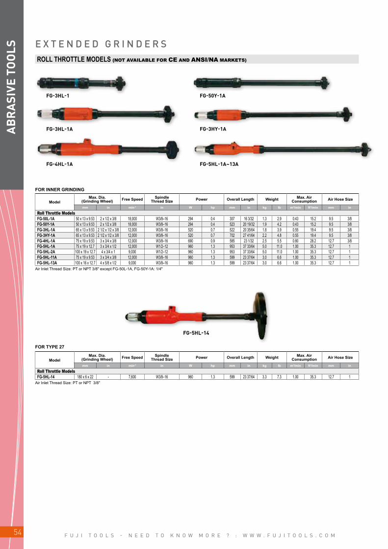
F U J I T O O L S - N E E D T O K N O W M O R E ? : W W W . F U J I T O O L S . C O M54
FG-3HL-1 FG-50Y-1A
FG-3HL-1A FG-3HY-1A
FG-4HL-1A
FG-5HL-14
FG-5HL-1A~13A
AB
RA
SIVE
TO
OLS E X T E N D E D G R I N D E R S
ModelMax. Dia.
(Grinding Wheel) Free Speed Spindle Thread Size Power Overall Length Weight Max. Air
Consumption Air Hose Size
mm in min-1 in W hp mm in kg lb m3/min ft3/min mm in
Roll Throttle ModelsFG-50L-1A 50 x 13 x 9.53 2 x 1/2 x 3/8 18,000 W3/8–16 294 0.4 307 16 3/32 1.3 2.9 0.43 15.2 9.5 3/8FG-50Y-1A 50 x 13 x 9.53 2 x 1/2 x 3/8 18,000 W3/8–16 294 0.4 523 20 19/32 1.9 4.2 0.43 15.2 9.5 3/8FG-3HL-1A 65 x 13 x 9.53 2 1/2 x 1/2 x 3/8 12,000 W3/8–16 520 0.7 522 20 35/64 1.8 3.9 0.55 19.4 9.5 3/8FG-3HY-1A 65 x 13 x 9.53 2 1/2 x 1/2 x 3/8 12,000 W3/8–16 520 0.7 702 27 41/64 2.2 4.8 0.55 19.4 9.5 3/8FG-4HL-1A 75 x 19 x 9.53 3 x 3/4 x 3/8 12,000 W3/8–16 690 0.9 585 23 1/32 2.5 5.5 0.80 28.2 12.7 3/8FG-5HL-1A 75 x 19 x 12.7 3 x 3/4 x 1/2 12,000 W1/2–12 960 1.3 953 37 33/64 5.0 11.0 1.00 35.3 12.7 1FG-5HL-2A 100 x 19 x 12.7 4 x 3/4 x 1 9,000 W1/2–12 960 1.3 953 37 33/64 5.0 11.0 1.00 35.3 12.7 1FG-5HL-11A 75 x 19 x 9.53 3 x 3/4 x 3/8 12,000 W3/8–16 960 1.3 599 23 37/64 3.0 6.6 1.00 35.3 12.7 1FG-5HL-13A 100 x 16 x 12.7 4 x 5/8 x 1/2 9,000 W3/8–16 960 1.3 599 23 37/64 3.0 6.6 1.00 35.3 12.7 1
ModelMax. Dia.
(Grinding Wheel) Free Speed Spindle Thread Size Power Overall Length Weight Max. Air
Consumption Air Hose Size
mm in min-1 in W hp mm in kg lb m3/min ft3/min mm in
Roll Throttle ModelsFG-5HL-14 180 x 6 x 22 - 7,600 W3/8–16 960 1.3 599 23 37/64 3.3 7.3 1.00 35.3 12.7 1
ROLL THROTTLE MODELS (NOT AVAILABLE FOR CE AND ANSI/NA MARKETS)
Air Inlet Thread Size: PT or NPT 3/8" except FG-50L-1A, FG-50Y-1A: 1/4"
Air Inlet Thread Size: PT or NPT 3/8"
FOR INNER GRINDING
FOR TYPE 27
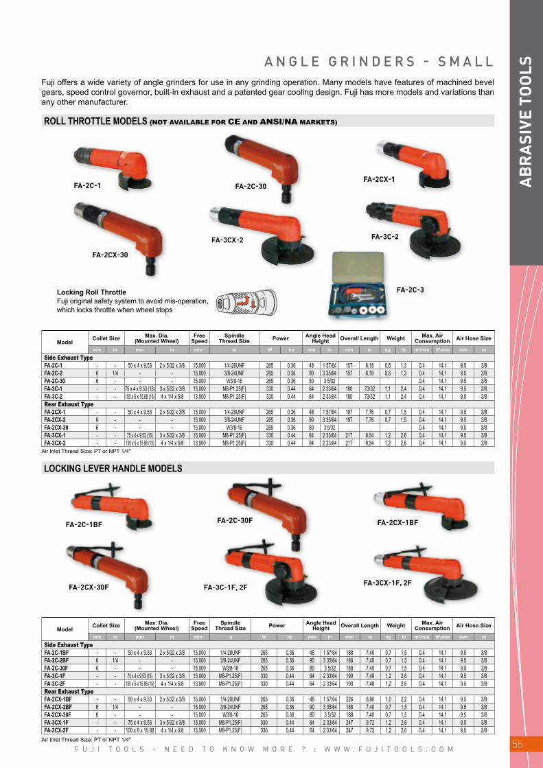
F U J I T O O L S - N E E D T O K N O W M O R E ? : W W W . F U J I T O O L S . C O M 55
FA-2C-1BF
FA-2C-1
FA-2CX-30
FA-3CX-2 FA-3C-2
FA-2C-3
FA-2C-30FA-2CX-1
FA-2CX-30F
FA-2C-30F FA-2CX-1BF
FA-3CX-1F, 2FFA-3C-1F, 2F
AB
RA
SIVE
TO
OLSA N G L E G R I N D E R S - S M A L L
Fuji offers a wide variety of angle grinders for use in any grinding operation. Many models have features of machined bevel gears, speed control governor, built-in exhaust and a patented gear cooling design. Fuji has more models and variations than any other manufacturer.
ROLL THROTTLE MODELS (NOT AVAILABLE FOR CE AND ANSI/NA MARKETS)
ModelCollet Size Max. Dia.
(Mounted Wheel)Free
SpeedSpindle
Thread Size Power Angle Head Height Overall Length Weight Max. Air
Consumption Air Hose Size
mm in mm in min-1 in W hp mm in mm in kg lb m3/min ft3/min mm in
Side Exhaust TypeFA-2C-1 - - 50 x 4 x 9.53 2 x 5/32 x 3/8 15,000 1/4-28UNF 265 0.36 48 1 57/64 157 6,18 0,6 1,3 0.4 14.1 9.5 3/8FA-2C-2 6 1/4 - - 15,000 3/8-24UNF 265 0.36 90 3 35/64 157 6,18 0,6 1,3 0.4 14.1 9.5 3/8FA-2C-30 6 - - - 15,000 W3/8-16 265 0.36 80 3 5/32 0.4 14.1 9.5 3/8FA-3C-1 - - 75 x 4 x 9.53 (15) 3 x 5/32 x 3/8 15,000 M8-P1.25(F) 330 0.44 64 2 33/64 180 73/32 1,1 2,4 0,4 14,1 9.5 3/8FA-3C-2 - - 100 x 6 x 15.88 (15) 4 x 1/4 x 5/8 13,500 M8-P1.25(F) 330 0.44 64 2 33/64 180 73/32 1,1 2,4 0,4 14,1 9.5 3/8Rear Exhaust TypeFA-2CX-1 - - 50 x 4 x 9.53 2 x 5/32 x 3/8 15,000 1/4-28UNF 265 0.36 48 1 57/64 197 7,76 0,7 1,5 0.4 14.1 9.5 3/8FA-2CX-2 6 - - - 15,000 3/8-24UNF 265 0.36 90 3 35/64 197 7,76 0,7 1,5 0.4 14.1 9.5 3/8FA-2CX-30 6 - - - 15,000 W3/8-16 265 0.36 80 3 5/32 0.4 14.1 9.5 3/8FA-3CX-1 - - 75 x 4 x 9.53 (15) 3 x 5/32 x 3/8 15,000 M8-P1.25(F) 330 0.44 64 2 33/64 217 8,54 1,2 2,6 0,4 14,1 9.5 3/8FA-3CX-2 - - 100 x 6 x 15.88 (15) 4 x 1/4 x 5/8 13,500 M8-P1.25(F) 330 0.44 64 2 33/64 217 8,54 1,2 2,6 0,4 14,1 9.5 3/8
LOCKING LEVER HANDLE MODELS
Air Inlet Thread Size: PT or NPT 1/4"
ModelCollet Size Max. Dia.
(Mounted Wheel)Free
SpeedSpindle
Thread Size Power Angle Head Height Overall Length Weight Max. Air
Consumption Air Hose Size
mm in mm in min-1 in W hp mm in mm in kg lb m3/min ft3/min mm in
Side Exhaust TypeFA-2C-1BF - - 50 x 4 x 9.53 2 x 5/32 x 3/8 15,000 1/4-28UNF 265 0.36 48 1 57/64 188 7,40 0,7 1,5 0.4 14.1 9.5 3/8FA-2C-2BF 6 1/4 - - 15,000 3/8-24UNF 265 0.36 90 3 35/64 188 7,40 0,7 1,5 0.4 14.1 9.5 3/8FA-2C-30F 6 - - - 15,000 W3/8-16 265 0.36 80 3 5/32 188 7,40 0,7 1,5 0.4 14.1 9.5 3/8FA-3C-1F - - 75 x 4 x 9.53 (15) 3 x 5/32 x 3/8 15,000 M8-P1.25(F) 330 0.44 64 2 33/64 190 7,48 1,2 2,6 0,4 14,1 9.5 3/8FA-3C-2F - - 100 x 6 x 15.88 (15) 4 x 1/4 x 5/8 13,500 M8-P1.25(F) 330 0.44 64 2 33/64 190 7,48 1,2 2,6 0,4 14,1 9.5 3/8Rear Exhaust TypeFA-2CX-1BF - - 50 x 4 x 9.53 2 x 5/32 x 3/8 15,000 1/4-28UNF 265 0.36 48 1 57/64 226 8,90 1,0 2,2 0.4 14.1 9.5 3/8FA-2CX-2BF 6 1/4 - - 15,000 3/8-24UNF 265 0.36 90 3 35/64 188 7,40 0,7 1,5 0.4 14.1 9.5 3/8FA-2CX-30F 6 - - - 15,000 W3/8-16 265 0.36 80 3 5/32 188 7,40 0,7 1,5 0.4 14.1 9.5 3/8FA-3CX-1F - - 75 x 4 x 9.53 3 x 5/32 x 3/8 15,000 M8-P1.25(F) 330 0.44 64 2 33/64 247 9,72 1,2 2,6 0,4 14,1 9.5 3/8FA-3CX-2F - - 100 x 6 x 15.88 4 x 1/4 x 5/8 13,500 M8-P1.25(F) 330 0.44 64 2 33/64 247 9,72 1,2 2,6 0,4 14,1 9.5 3/8
Air Inlet Thread Size: PT or NPT 1/4"
Locking Roll ThrottleFuji original safety system to avoid mis-operation, which locks throttle when wheel stops
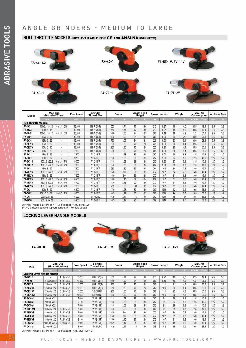
F U J I T O O L S - N E E D T O K N O W M O R E ? : W W W . F U J I T O O L S . C O M56
FA-4C-1,3
FA-6C-1
FA-40-1F FA-6C-8M FA-7E-8VF
FA-5E-1V, 3V, 11V
FA-7E-2V
FA-40-1
FA-7C-1
AB
RA
SIVE
TO
OLS A N G L E G R I N D E R S - M E D I U M T O L A R G E
ROLL THROTTLE MODELS (NOT AVAILABLE FOR CE AND ANSI/NA MARKETS)
ModelMax. Dia.
(Mounted Wheel) Free Speed Spindle Thread Size Power Angle Head
Height Overall Length Weight Max. Air Consumption Air Hose Size
mm in min-1 in W hp mm in mm in kg lb m3/min ft3/min mm in
Roll Throttle ModelsFA-4C-1 100 x 6 x 15.88 (15) 4 x 1/4 x 5/8 13,500 M8-P1.25(F) 550 0.74 77 3.0 210 8,27 1.8 4.0 0.55 19.4 9.5 3/8FA-4C-3 100 x 6 x 15 - 13,500 M8-P1.25(F) 550 0.74 77 3.0 210 8,27 1.8 4.0 0.55 19.4 9.5 3/8FA-40-1 100 x 6 x 15.88 (15) 4 x 1/4 x 5/8 13,500 M8-P1.25(F) 1000 1.36 74 2.9 208 8,19 1.9 4.2 1.0 35.3 9.5 3/8FA-5C-1 125 x 6 x 22 - 10,900 M8-P1.25(F) 790 1.06 84 3.3 226 8,90 2.3 5.14 0.80 28.3 9.5 3/8FA-5C-4 125 x 6 x 22 - 12,000 M8-P1.25(F) 790 1.06 84 3.3 226 8,90 2.3 5,1 0.80 28.3 9.5 3/8FA-5E-1V 125 x 6 x 22 - 10,900 M8-P1.25(F) 960 1.30 70 2.8 225 8.90 2.0 4.4 0.95 33.5 9.5 3/8FA-5E-3V 100 x 6 x 15 - 13,500 M8-P1.25(F) 960 1.30 70 2.8 225 8.90 2.0 4.4 0.95 33.5 9.5 3/8FA-5E-11V 180 x 6 x 22 - 7,600 M8-P1.25(F) 960 1.30 70 2.8 225 8.90 2.0 4.4 0.95 33.5 9.5 3/8FA-6C-1 180 x 6 x 22 - 7,600 W1/2-16(F) 1180 1.58 89 3.5 252 9.90 2.9 6.3 1.15 40.6 12.7 1/2FA-6C-7 150 x 6 x 22 - 9,100 W1/2-16(F) 1180 1.58 89 3.5 252 9.90 2.7 5.9 1.15 40.6 12.7 1/2FA-6C-10 150 x 6 x 22.2 6 x 1/4 x 7/8 9,000 W1/2-16(F) 1180 1.58 89 3.5 252 9.90 2.7 5.9 1.15 40.6 12.7 1/2FA-6C-12 180 x 6 x 22.2 7 x 1/4 x 7/8 7,600 W1/2-16(F) 1180 1.58 89 3.5 252 9.90 2.9 6.3 1.15 40.6 12.7 1/2FA-7C-1 180 x 6 x 22 - 7,600 W1/2-16(F) 960 1.30 89 3.5 264 10.4 3.4 7.5 1.40 49.4 12.7 1/2FA-7E-1V 180 x 6 x 22.2 7 x 1/4 x 7/8 7,000 W1/2-16(F) 1500 2.0 89 3.5 272 10,7 3.4 7.5 1.40 49.4 12.7 1/2FA-7E-2V 180 x 6 x 22 - 7,600 W1/2-16(F) 1500 2.0 89 3.5 272 10,7 3.1 6.8 1.40 49.4 12.7 1/2FA-7E-3V 180 x 6 x 22.2 7 x 1/4 x 7/8 8,400 W1/2-16(F) 1590 2.15 87 3,4 272 10,7 3.1 6.8 1.40 49.4 12.7 1/2FA-7E-4V 180 x 6 x 22.2 7 x 1/4 x 7/8 8,400 W1/2-16(F) 1590 2.15 92 3,6 272 10,7 3.1 6.8 1.40 49.4 12.7 1/2FA-7E-5V 180 x 6 x 22.2 7 x 1/4 x 7/8 7,600 W1/2-16(F) 960 1.30 100 3.9 272 10,7 3.1 6.8 1.40 49.4 12.7 1/2FA-9C-1 205 x 8 x 22 - 6,600 W1/2-16(F) 1700 2.28 89 3.5 309 121/6 4.2 9.2 1.65 58.3 12.7 1/2FA-9C-2 230 x 9.5 x 22.2 9 x 3/8 x 7/8 5,900 W1/2-16(F) 1620 2,17 95 3.7 309 121/6 4.4 9.7 1.65 58.3 12.7 1/2FA-9C-4 230 x 9.5 x 22 - 5,900 5/8-11UNC 1620 2,17 116 4.6 309 121/6 4.8 10.6 1.65 58.3 12.7 1/2FA-9C-6 230 x 9.5 x 22 - 5,900 W1/2-16(F) 1620 2,17 95 3.7 309 121/6 4.3 9.5 1.65 58.3 12.7 1/2
Air Inlet Thread Size: PT or NPT 3/8" except FA-9C serie 1/2"FA-4C-3 does not have support handle. (F): Female thread
LOCKING LEVER HANDLE MODELS
ModelMax. Dia.
(Mounted Wheel) Free Speed Spindle Thread Size Power Angle Head
Height Overall Length Weight Max. Air Consumption Air Hose Size
mm in min-1 in W hp mm in mm in kg lb m3/min ft3/min mm in
Locking Lever Handle ModelsFA-4C-1F - 4 x 1/4 x 5/8 13,500 M8-P1.25(F) 550 0.74 77 3.0 210 8.27 1,8 4,0 0.55 19.4 9.5 3/8FA-40-1F 100 x 6 x 15.88 (15) 4 x 1/4 x 5/8 13,500 M8-P1.25(F) 1000 1.36 74 2.9 208 8.19 1,9 4,2 1.0 35.3 9.5 3/8FA-5E-2F 125 x 6 x 22.2 5 x 1/4 x 7/8 12,000 M8-P1.25(F) 960 1.30 70 2.8 282 11.1 2.1 4.6 0.95 33.5 9.5 3/8FA-5E-2VF 125 x 6 x 22.2 5 x 1/4 x 7/8 12,000 M8-P1.25(F) 960 1.30 70 2.8 262 10.6 2.0 4.4 0.95 33.5 9.5 3/8FA-5E-13F 125 x 6 x 22.2 5 x 1/4 x 7/8 12,000 3/8-24 UNF 960 1.30 70 2.8 282 11.1 2.2 4.8 0.95 33.5 9.5 3/8FA-5E-13VF 125 x 6 x 22.2 5 x 1/4 x 7/8 12,000 3/8-24 UNF 960 1.30 70 2.8 262 10.6 2.2 4.8 0.95 33.5 9.5 3/8FA-6C-6M 180 x 6 x 22 - 7,600 W1/2-16(F) 1180 1.58 89 3.5 252 9.9 2.9 6.3 1.15 40.6 12.7 1/2FA-6C-8M 150 x 6 x 22 - 9,100 W1/2-16(F) 1180 1.58 89 3.5 252 9.9 2.7 5.9 1.15 40.6 12.7 1/2FA-6C-9M 180 x 6 x 22 - 7,600 W1/2-16(F) 1180 1.58 89 3.5 252 9.9 2.9 6.3 1.15 40.6 12.7 1/2FA-6C-12M 180 x 6 x 22.2 7 x 1/4 x 7/8 7,600 W1/2-16(F) 1180 1.58 89 3.5 252 9.9 2.9 6.3 1.15 40.6 12.7 1/2FA-7E-5VF 180 x 6 x 22.2 7 x 1/4 x 7/8 7,000 W1/2-16(F) 1500 2.0 89 3.5 272 10.7 3.4 7.5 1.40 49.4 12.7 1/2FA-7E-6VF 180 x 6 x 22.2 7 x 1/4 x 7/8 7,600 W1/2-16(F) 1500 2.0 89 3.5 272 10.7 3,1 6,8 1.40 49.4 12.7 1/2FA-7E-8VF 180 x 6 x 22.2 7 x 1/4 x 7/8 8,400 W1/2-16(F) 1590 2.15 87 3.4 272 10.7 3,1 6,8 1.40 49.4 12.7 1/2FA-9C-2M 230 x 9.5 x 22.2 9 x 3/8 x 7/8 5,900 W1/2-16(F) 1620 2,17 95 3.7 385 15.2 4.5 9.9 1.40 49.4 12.7 1/2FA-9C-4M 230 x 9.5 x 22 - 5,900 5/8-11UNC 1620 2,17 116 4.6 385 15.2 4.5 9.9 1.65 58.3 12.7 1/2
Air Inlet Thread Size: PT or NPT 3/8" except FA-9C-2M/-4M: 1/2"
F U J I T O O L S - N E E D T O K N O W M O R E ? : W W W . F U J I T O O L S . C O M 57
FA-5C-5 (90°)
FA-150KG-7 (120°)
FA-150K-20 (120°)
FA-5E-7V (90°)
FA-3CK-1 (120°)
FA-3CK-2(120°)
FA-150KG-5 (120°)
AB
RA
SIVE
TO
OLSA N G L E G R I N D E R S - S A N D E R S
ANGLE GRINDER - ROLL THROTTLE MODELS (NOT AVAILABLE FOR CE AND ANSI/NA MARKETS)
ModelMax. Dia.
(Mounted Wheel) Free Speed Spindle Thread Size Power Angle Head
Height Overall Length Weight Max. Air Consumption Air Hose Size
mm in min-1 in W hp mm in mm in kg lb m3/min ft3/min mm in
Roll Throttle ModelsFA-3CK-2 100 x 6 x 15.88 (15) 4 x 1/4 x 5/8 13,500 M8-1.25P(F) 340 0.4 78 3 5/64 164 6 1/2 1.2 2.6 0.40 14.1 9.5 3/8FA-150KG-5 180 x 6 x 22 - 7,600 W1/2-16(F) 900 1.2 98 4 245 9 5/8 1.8 3.9 1.15 40.6 12.7 1/2
Air Inlet Thread Size: PT or NPT FA-3CK-2: 1/4", FA-150KG-5: 3/8"FA-3CK-2 has roll throttle, does not have support handle.(F): Female thread
ANGLE SANDER - ROLL THROTTLE MODELS (NOT AVAILABLE FOR CE AND ANSI/NA MARKETS)
ModelMax. Dia. Free
SpeedSpindle
Thread Size Power Angle Head Height Overall Length Weight Max. Air
Consumption Air Hose SizeSanding Disc Wire Brushmm in mm in min-1 in W hp mm in mm in kg lb m3/min ft3/min mm in
Roll Throttle ModelsFA-5C-5 180 x – x 22.2 7 x – x 7/8 - - 7,000 W1/2-16(F) 670 0.8 85 3 11/32 230 9 2.1 4.6 0.58 20.5 9.5 3/8FA-5E-7V 180 x – x 22.2 7 x – x 7/8 - - 7,000 M8-1.25P(F) 960 1.3 70 2 3/4 212 8 11/32 1.9 4.2 0.95 33.5 9.5 3/8•FA-3CK-1 100 x – x 15.9 4 x – x 7/8 - 11,000 3/8-24UNF(M) 340 0.4 79 3 7/64 164 6 29/64 1.1 2.2 0.40 14.1 9.5 3/8FA-150KG-7 180 x – x 22.2 7 x – x 7/8 125 x – x 15.9 5 x – x 5/8 5,500 W1/2-16(F) 900 1.2 87 3 27/64 245 9 41/64 1.8 4.0 1.15 40.6 12.7 1/2•FA-150K-20 150 x – x 22.2 7 x – x 7/8 125 x – x 15.9 5 x – x 5/8 8,400 W1/2-16(F) 900 1.2 80 3 5/32 210 8 17/64 1.6 4.0 1.00 35.3 12.7 1/2
Air Inlet Thread Size: PT or NPT 3/8" except FA-3CK-1: 1/4"FA-150KG-7 has a flange for Shank brush. In case of paper sanding you needs flange for paper sanding.• Models do not have support handle. (F): Female thread (M): Male thread

F U J I T O O L S - N E E D T O K N O W M O R E ? : W W W . F U J I T O O L S . C O M58
FA-5E-6VF FA-7E-5VF
FG-5PX-1
FA-5E-8V FA-7C-21
AB
RA
SIVE
TO
OLS A N G L E S A N D E R S / A N G L E C U T T E R S
ANGLE SANDERS - LOCKING LEVER HANDLE MODELS
ModelMax. Dia. Free
Speed Power Overall Length Weight Max. Air Consumption Air Hose SizeSanding Disc Wire Brush
mm in mm in min-1 W hp mm in kg lb m3/min ft3/min mm in
3/8-24UNF Thread Male Spindle TypeFA-5E-6VF 180 x – x 22.2 7 x – x 7/8 - - 6,000 960 1.29 262 10 5/16 2.0 4.4 0.95 33.5 9.5 3/85/8-11UNC Thread Male Spindle TypeFA-7E-5VF 180 x – x 22.2 7 x – x 7/8 - - 7,000 1620 2.17 307 12 3/32 3.1 6.8 1.40 49.4 12.7 1/2
Air Inlet Thread Size: PT or NPT 3/8". *Specify Sanding Discs or Wire Brushes when ordering.
ANGLE SANDERS - DISC TYPE
ModelMax Dia.
(Sanding Disc)Free
Speed Height Power Overall Length Weight Max. Air Consumption Air Hose Size
mm in min-1 mm in W hp mm in kg lb m3/min ft3/min mm in
FG-5PX-1 125 x – x 22.2 5 x – x 7/8 12,000 170 6 11/16 370 0.49 108 4 1/4 1.0 2.2 0.50 17.7 9.5 3/8Air Inlet Thread Size: PT or NPT 1/4".
Height
Overall Length
This Sander features rear exhaust, low noise, high speed and comfortable design. It is useful for various sanding work.
Air Inlet Thread Size: PT or NPT 3/8". (F): Female thread
ModelMax. Dia. Free
SpeedSpindle
Thread Size Power Angle Head Height Overall Length Weight Max. Air
Consumption Air Hose Size
mm in min-1 in W hp mm in mm in kg lb m3/min ft3/min mm in
Side Exhaust TypeFA-5E-8V 125 x 2 x 20 - 10,900 M8-1.25P(F) 960 1.3 74 3 213 8 25/64 2.0 4.4 0.95 33.2 9.5 3/8FA-7C-21 180 x 2 x 25.5 - 7,600 W1/2-16(F) 1280 1.7 91 3 37/64 264 10 25/64 3.4 7.5 1.40 49.0 12.7 1/2
ANGLE CUTTERS - ROLL THROTTLE MODELS (NOT AVAILABLE FOR CE AND ANSI/NA MARKETS)FOR DIAMOND CUTTER

F U J I T O O L S - N E E D T O K N O W M O R E ? : W W W . F U J I T O O L S . C O M 59
FV-7-1M,4M
FV-9BH-4M
FV-7-2M
FV-9BH-1M
AB
RA
SIVE
TO
OLS
LOCKING LEVER HANDLE MODELS
V E R T I C A L G R I N D E R S - V E R T I C A L S A N D E R S
Fuji Vertical Grinders are very powerful due to their direct drive shafts. All vertical grinders feature a centrifugal speed control governor that maintains rotational frequency even under a heavy grinding load. All Models are 5/8"-11UNC male spindle type with locking lever handle.
VERTICAL GRINDERS STANDARD TYPE
Air Inlet Thread Size: PT or NPT 3/8", FV-9BH Series: PT or NPT 1/2".
ModelMax. Dia.
(Grinding Wheel) Free Speed Height Power Overall Length Weight Max. Air Consumption Air Hose Size
mm in min-1 mm in W hp mm in kg lb m3/min ft3/min mm in
FV-7-1M 180 x 6 x 22.23 (22) 7 x 1/4 x 7/8 6,000 192 7 9/16 1400 1.87 247 9 23/32 4.0 8.8 1.40 49.4 12.7 1/2FV-7-4M 180 x 6 x 22.23 (22) 7 x 1/4 x 7/8 8,400 192 7 9/16 1760 2.37 247 9 23/32 4.0 8.8 1.70 60.0 12.7 1/2FV-9BH-1M 230 x 8 x 22.23 (22) 9 x 5/16 x 7/8 5,900 222 8 47/64 2900 3.88 278 10 61/64 5.8 12.7 2.80 98.9 19.0 3/4
Air Inlet Thread Size: PT or NPT 1/2".
VERTICAL GRINDERS CUP WHEEL TYPE
Overall Length
Height (Height is a distance from wheel flange to top)
ModelMax Dia.
(Cup Wheel) Free Speed Height Power Overall Length Weight Max. Air Consumption Air Hose Size
mm in min-1 mm in W hp mm in kg lb m3/min ft3/min mm in
FV-9BH-4M 150 x 50 x 22.2 6 x 2 x 7/8 4,500 204 8 1/32 2900 3.88 278 10 61/64 6.1 13.4 2.40 84.7 19.0 3/4
SANDING DISC TYPE
Air Inlet Thread Size: PT or NPT 3/8".
ModelMax Dia.
(Sanding Disc) Free Speed Height Power Overall Length Weight Max. Air Consumption Air Hose Size
mm in min-1 mm in W hp mm in kg lb m3/min ft3/min mm in
FV-7-2M 180 x – x 22.2 7 x – x 7/8 7,000 192 7 9/16 1540 2.07 247 9 23/32 4.0 8.8 1.60 56.5 12.7 1/2v

F U J I T O O L S - N E E D T O K N O W M O R E ? : W W W . F U J I T O O L S . C O M60
FBS-1-1,3
FBS-1-2,4
AB
RA
SIVE
TO
OLS
ACCESSORIESCONTACT ARM ASSEMBLY
SANDING BELTS
ModelBelt Size Free
SpeedBelt
Speed Power Overall Length Height Weight Max. Air Consumption Air Hose Size
mm in min-1 m/min W hp mm in mm in kg lb m3/min ft3/min mm in
FBS-1-1 10 x 330 13/32 x 12 1/64 20,000 1,200 280 0.37 281 11 5/64 124 4 57/64 1.1 2.4 0.57 20.1 9.5 3/8FBS-1-2 20 x 520 51/64 x 19 1/2 20,000 1,200 280 0.37 375 14 25/32 124 4 57/64 1.2 2.6 0.57 20.1 9.5 3/8FBS-1-3 13 x 460 33/64 x 18 1/8 20,000 1,200 280 0.37 345 13 19/32 124 4 57/64 1.2 2.6 0.57 20.1 9.5 3/8FBS-1-4 20 x 460 51/64 x 18 1/8 20,000 1,200 280 0.37 345 13 19/32 124 4 57/64 1.2 2.6 0.57 20.1 9.5 3/8
Air Inlet Thread Size: PT or NPT 1/4".
Sanding Belts in different size are able to be mounted to the tool by replacing Contact Arm Ass'y.
*Marked • are Standard Accessories.
Applicable Model
Belt Size (mm)
Grit #40
Grit #60
Grit #80
Grit #100
Grit #120
FBS-1-1 10 x 330 DSB-271 DSB-273 •DSB-274 DSB-275 DSB-276FBS-1-2 20 x 520 DSB-261 DSB-263 •DSB-264 DSB-265 DSB-266FBS-1-3 13 x 460 DSB-221 DSB-223 •DSB-224 DSB-225 DSB-226FBS-1-4 20 x 460 DSB-241 DSB-243 •DSB-244 DSB-245 DSB-246
Contact Arm Ass'y Size Model
FBS-1-1 10 x 330 DSB-271FBS-1-2 20 x 520 DSB-261FBS-1-3 13 x 460 DSB-221FBS-1-4 20 x 460 DSB-241
ANGLE ADJUSTMENT
(UP TO 360 DEGREES)
B E L T S A N D E R SFuji Belt Sanders are ideal for precise and efficient sanding of confined areas such as spherical surfaces and tubes which are difficult to access with conventional grinders. They are also the ideal tool for de-burring applications.360 degree head rotation provides versatile solution for almost any application.
Flat Sanding
Round Chamfering
Inside Corner Sanding
Sanding in Narrow Space Corner Chamfering
Chamfering of Small Pipe
Flat Finishing
Grinding of Welding Beads
Spacer Needle Roller
Guide Roller
Ball Bearing
Pad
Guide Roller Spindle

F U J I T O O L S - N E E D T O K N O W M O R E ? : W W W . F U J I T O O L S . C O M 61
DA-125C
OB-75L, 90L FOS-175B
FOR-125B, 150B FOR-125BF, 150BF
AB
RA
SIVE
TO
OLSO R B I T A L S A N D E R S
Fuji Orbital Sanders are compact, lighweight & manœuvrable, yet powerful enough for finishing lacquered and metal surfaces prior to re-painting. The effective dust extraction with rear exhaust helps keep the working environment clean.
Features n Powerful sanding, high stability and low vibration. n Excellent dust extraction ability tohelp keep the work area clean n Available to suit variations of sandpapers; self-adhesive type, Velcro (Nylon Strip Fastener) Type and standard Clip-on Type.
ModelCapacity
(Sanding Disc)Free
SpeedAngle Head
Height Power Overall Length Weight Max. Air Consumption Air Hose Size
mm in min-1 mm in W hp mm in kg lb m3/min ft3/min mm in
Lever Handle ModelsDA-125L-E(M) ø125 5 8,500 94 3 45/64 60 0.079 158 6 7/32 1.2 2.6 0.26 9.1 6.3 1/4DA-125C-E(M) ø125 5 8,500 107 4 7/32 60 0.079 158 6 7/32 1.4 3.0 0.26 9.1 6.3 1/4FOR-125B-E(M) ø125 5 8,000 124 4 7/8 118 0.158 243 9 9/16 2.0 4.4 0.36 12.7 6.3 1/4FOR-150B-E(M) ø150 6 8,000 124 4 7/8 118 0.158 256 10 5/64 2.1 4.6 0.36 12.7 6.3 1/4Locking Lever Handle ModelsFOR-125BF-E(M) ø125 5 8,000 124 4 7/8 118 0.158 243 9 9/16 2.0 4.4 0.36 12.7 6.3 1/4FOR-150BF-E(M) ø150 6 8,000 124 4 7/8 118 0.158 256 10 5/64 2.1 4.6 0.36 12.7 6.3 1/4
ModelCapacity
(Sanding Pad Size)Free
SpeedAngle Head
Height Power Overall Length Weight Max. Air Consumption Air Hose Size
mm in min-1 mm in W hp mm in kg lb m3/min ft3/min mm in
Lever Handle ModelsOB-75L-E(M) 75 x 100 3 x 4 7,000 91 3 37/64 60 0.079 145 5 45/64 1.2 2.6 0.26 9.1 6.3 1/4OB-90L-E(M) 90 x 100 3.5 x 4 7,000 91 3 37/64 60 0.079 145 5 45/64 1.3 2.8 0.26 9.1 6.3 1/4FOS-175B-E(M) 100 x 175 4 x 7 6,500 130 5 1/8 118 0.158 268 10 9/16 2.4 5.2 0.34 11.9 6.3 1/4FOS-230B-E 100 x 230 4 x 9 6,000 130 5 1/8 118 0.158 291 11 29/64 2.6 5.7 0.34 11.9 6.3 1/4Locking Lever Handle ModelsFOS-175BF-E(M) 100 x 175 4 x 7 6,500 130 5 1/8 118 0.158 268 10 9/16 2.4 5.2 0.34 11.9 6.3 1/4FOS-230BF-E 100 x 230 4 x 9 6,000 130 5 1/8 118 0.158 291 11 29/64 2.6 5.7 0.34 11.9 6.3 1/4
DISC TYPE
RECTANGLE SHEET TYPE
Air Inlet Thread Size: PT or NPT 1/4".*Adhesive paper type: (E). *Velcro paper type : (M).*DA-125 Series, Orbit5mm (3/16")- FOR-125/-150 Series, Orbit 9mm (11/32")
Air Inlet Thread Size: PT or NPT 1/4".*Adhesive paper type: (E). *Velcro paper type : (M).*OB-75/-90 Series, Orbit 3mm (1/8") - FOS-175/-230/-400 Series, Orbit 5mm (3/16")
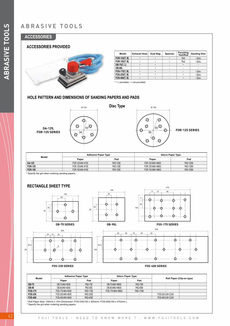
F U J I T O O L S - N E E D T O K N O W M O R E ? : W W W . F U J I T O O L S . C O M62
95
Ø 124
4334
Ø 150
5536
OB-75 SERIES OB-90L FOS-175 SERIES
100
100175
29
20
76
100
35.5 35.5
224400
2022 18 43 3239
15 32
9
9025
3
17 27 46
29
10020
FOS-230 SERIES FOS-400 SERIES
AB
RA
SIVE
TO
OLS
* Specify the grit when ordering sanding papers.
* Roll Paper Size: 100mm x 15m (Dimension: FOS-230(100 x 300)mm, FOS-400(100 x 470)mm.)* Specify the grit when ordering sanding papers.
A B R A S I V E T O O L S
ACCESSORIES PROVIDED
HOLE PATTERN AND DIMENSIONS OF SANDING PAPERS AND PADS
Model Exhaust Hose Dust Bag Spanner Punching Tool/Rod Sanding Disc
FOR-125(T, B) • • • Rod • 2pcs.FOR-150(T, B) • • • Rod • 2pcs.OB-75(T, L) • • - • -OB-90L • • - - -FOS-175(T, B) • • - - • 2pcs.FOS-230(T, B) • • - • • 2pcs.FOS-400(T, B) • • - • • 2pcs.
* • = provided,- = not provided
Disc Type
RECTANGLE SHEET TYPE
DA-125, FOR-125 SERIES
FOR-125 SERIES
ModelAdhesive Paper Type Velcro Paper Type
Paper Pad Paper PadDA-125 FOR-125-#40~#150 PAD-125E FOR-125-M40~M600 PAD-125MFOR-125 FOR-125-#40~#150 PAD-125E FOR-125-M40~M600 PAD-125MFOR-150 FOR-150-#40~#150 PAD-150E FOR-150-M40~M600 PAD-150M
ModelAdhesive Paper Type Velcro Paper Type
Roll Paper (Clip-on type)Paper Pad Paper Pad
OB-75 OB-75-#40~#240 PAD-75E OB-75-M40~M600 PAD-75M -OB-90 OB-90-#40~#240 PAD-90E OB-90-M40~M600 PAD-90M -FOS-175 FOS-175-#40~#240 PAD-175E FOS-175-M40~M600 PAD-175M -FOS-230 FOS-230-#40~#240 PAD-230E - - FOS-230-C40~C240FOS-400 FOS-400-#40~#240 PAD-400E - - FOS-400-C40~C240
ACCESSORIES
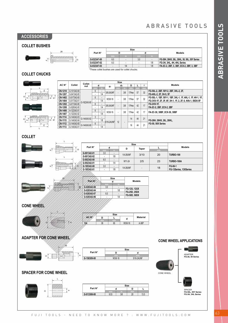
F U J I T O O L S - N E E D T O K N O W M O R E ? : W W W . F U J I T O O L S . C O M 63
L
D d d1 d2
L
DD
dd
d Ø8
L
25
L
D d
39
D d
D d
L
L
D d d1 d2
AB
RA
SIVE
TO
OLSA B R A S I V E T O O L S
COLLET BUSHES
COLLET CHUCKS
COLLET
26
d D
Part N°Size
ModelsD dmm in mm in
G-032347-00 6.0 - 3.0 - FG-26H, 26HX, 26L, 26HL, 50, 50L, 50Y SeriesG-032347-02 6.0 - - 1/8 FG-3H, 3HL, 4H, 4HL SeriesG-032347-03 - 1/4 - 1/8 FA-2C-2, 2BF, 3, 3BF, 2CX-2, 2BF, 3, 3BF
*These collet bushes are used for collet chucks.
AC N° Collet Collet nut
SizeModelsd d1
d2 D Lmm in mm in mm mm mm
CN-1210 G-101342-00
G-162343-00
6 - 3/8-24UNF - 3/8 17Hex 57 32 FG-50L-2, 2BF, 50Y-2, 2BF, 3HL-2, 2F, FG-4HL-2, 2F, 3H-5, 5FCN-1207 G-041342-00 - 1/4
CN-1402 G-017342-00 6 - W3/8-16 - 3/8 17Hex 57 32 FG-50L-1, 1BF, 50Y-1, 1BF, 3HL-1, 1F, 4HL-1, 1F, 4H-1, 1F, FG-3VX-1F, 2F, 3F, 6F, 3H-1, 1F, 2, 2F, 6, 4VA-1, 50DX-5FCN-1404 G-017342-01 - 1/4
CN-1202 G-011342-00 6 - 3/8-24UNF - 3/8 17Hex 42 17 FG-2VX-1F, FA-2C-2, 2BF, 2CX-2, 2BFCN-1208 G-028342-00 - 1/4
CN-1406 A-122342-01 6 - W3/8-16 - 3/8 17Hex 42 17 FA-2C-30, 30BF, 2CX-30, 30BFCN-1407 A-122342-02 - 1/4CN-1114 G-144342-03 G-144343-02 3 -
5/16-24UNF 12 -14 44 21 FG-26H, 26HX, 26L, 26HL,
FG-50, 50X SeriesCN-1115 G-144342-04 - 1/8CN-1112 G-144342-00 G-144343-00 6 - 16 44 21CN-1113 G-144342-01 - 1/4
Part N°Size
Modelsd D Taper Lmm in mm
G-001342-01 3.0 - 1/4-28UNF 3/10 20 TURBO-100G-001342-02 - 1/8G-002342-00 6.0 - W11-24 2/5 23 TURBO-100AG-002342-01 - 1/4G-185342-00 3.0 - 1/4-28UNF - 18 FG-06-1
FG-13Series, 13XSeriesG-185342-01 - 1/8
Part N°Size
Modelsdmm in
G-028342-08 3.0 - FG-12U, 12UX FG-25D, 25DX FG-50D, 50DX
G-028342-04 - 1/8G-028342-07 6.0 -G-028342-06 - 1/4
AC N°Size
MaterialD L dmm mm
124 38 65 W3/8-16 A-36P
Part N°Size
D dmm mm
G-158309-00 W3/8-16 5/16-24UNF
Part N°Size
d D Lmm in mm
G-013308-00 9.53 3/8 20 13.5
CONE WHEEL
ADAPTER FOR CONE WHEEL
SPACER FOR CONE WHEEL CONE WHEEL
ADAPTERFG-26, 50 Series
SPACER FG-50L, 50Y SeriesFG-3H, 3HL Series
CONE WHEEL APPLICATIONS
ACCESSORIES
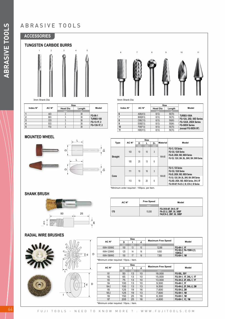
F U J I T O O L S - N E E D T O K N O W M O R E ? : W W W . F U J I T O O L S . C O M64
L
L
D D1
D1D
50 25
�Ø6
Ø15
D
D
d
d
t
t
AB
RA
SIVE
TO
OLS
TUNGSTEN CARBIDE BURRS1
62
73
84
95
10 11
3mm Shank Dia 6mm Shank Dia
Index N° AC N°Size
ModelHead Dia Lengthmm in
1 A03 3 38 FG-06-1 TURBO-100 FG-13-1F, 2 FG-13X-1F, 2
2 B03 3 383 C03 3 384 E03 3 385 F03 3 38
Index N° AC N°Size
ModelHead Dia Lengthmm in
6 A08(A13) 8(13) 55(70) TURBO-100AFG-12U, 25D, 50D SeriesFG-12UX, 25DX SeriesFG-50DX Series(except FG-50DX-5F)
7 B08(B13) 8(13) 55(75)8 C08(C13) 8(13) 55(60)9 E08(E13) 8(13) 55(84)10 F08(F13) 8(13) 55(75)11 H08(H13) 8(13) 55(70)
MOUNTED WHEELType AC N°
SizeMaterial ModelD L D1
mm mm mm
Straight
103 10 10 3
WA-60
FG-13, 13X SeriesFG-12U, 12UX SeriesFG-25, 25DX, 50D, 50DX Series
105 25 13 6FG-12U, 12UX, 26H, 26L, 26HX, 50H, 50HX Series
Cone
111 10 16 3
WA-60
FG-13, 13X SeriesFG-12U, 12UX SeriesFG-25, 25DX, 50D, 50DX Series
113 19 25 6FG-12U, 12UX, 26H, 26L, 26HX, 50H, 50HX SeriesFG-25D, 25DX, 50D, 50DX Series, 3H-5, 5FFG-3VX-6F, FA-2C-2, 30, 2CX-2, 30 Series
*Minimum order required : 100pcs. per item.
SHANK BRUSH
RADIAL WIRE BRUSHES
AC N° Free Speed Modelmin-1
170 15,000FG-3VX-6F, 3H-5, 5FFA-2C-2, 2BF, 30, 30BFFA2CX-2, 2BF, 30, 30BF
AC N°Size
Maximum Free Speed ModelD t dmm mm mm min-1
KWH-100WK5 100 13 10 12,000 FG-4H-1, 1FKWH-123WK5 125 14 16 9,500 FG-5H-2, FA-150K-2,3,
150KG-7KWH-156WK5 150 17 16 7,500 FG-6H-1, 1M
AC N°Size
Maximum Free Speed ModelD t dmm mm mm min-1
181 50 13 10 18,000 FG-50L, 50Y182 65 13 10 15,000 FG-3H-1, 1F, 3HL-1, 1F183 75 13 10 13,000 FG-3H-2, 2F, 4HL-1, 1F184 100 13 10 9,500 FG-4H-1, 1F
184-2 100 13 13 9,500 FG-4H-2, 2F, 5HL-2, 2M185 125 19 16 7,600 FG-5H-2, 2M
185-2 125 19 13 7,600 FG-5H-1, 1M186 150 25 16 6,300 FG-6H-1, 1M187 205 25 16 4,600 FG-8H-1, 1C, 1M
*Minimum order required :10pcs. / item.
*Minimum order required :10pcs. / item.
A B R A S I V E T O O L S
ACCESSORIES

F U J I T O O L S - N E E D T O K N O W M O R E ? : W W W . F U J I T O O L S . C O M 65
d
t
D
Fig 1.
Fig 2.Fig 3.
Fig 8.
Fig 4.
Fig 6.
Fig 7.
Fig 4.
Fig 6.
Fig 7.
Fig 8. Fig 5.Fig 4.
Fig 6.
Fig 7.
Fig 1.
14 10
10
5
5
D
1/4-
28U
NF
6øD
29.5
4014
Fig 2.
AB
RA
SIVE
TO
OLSA B R A S I V E T O O L S
* • = Minimum order required :100pcs. / item, others = Minimum order required : 50pcs. / item.
STRAIGHT GRINDING WHEELS FOR STRAIGHT AND EXTENSION GRINDERS
HEAT SHRINK-TUBES FOR EXTENSION GRINDERS
ACCESSORIES FOR FA-2C, -2CX SERIES
ATTACHMENTS
AC N°Size
MaterialMaximum Free
Speed ModelsD t dmm in mm in mm in min-1
•131 50 2 13 1/2 9.53 3/8 A-36Q 18,000 FG-50L, -50Y Series•132 65 2 1/2 13 1/2 9.53 3/8 A-30R 14,000 FG-3H-1, 1F, 3HL-1, 1F, 2, 2F•133 75 3 13 1/2 9.53 3/8 A-24P 12,000 FG-3H-2, 2F, 4HL-1, 1F, 2, 2F
•133-1 75 3 19 3/4 9.53 3/8 A-24P 12,000 FG-4HL-1, 1F, 2, 2F•134 100 4 19 3/4 9.53 3/8 A-24P 9,000 FG-4H-1, 1F
•136-2 125 5 19 3/4 12.70 1/2 A-24P 7,600 FG-5H-1, 1M•137 125 5 19 3/4 15.88 5/8 A-24P 7,600 FG-5H-2, 2M•138 150 6 25 1 15.88 5/8 A-24P 6,300 FG-6H-1, 1M•139 180 7 25 1 15.88 5/8 A-24P 5,300 FG-8H-2 Series•140 205 8 25 1 15.88 5/8 A-24P 4,600 FG-8H-1 Series
AC N° LengthBefore After
Object Size ModelsInside Dia. Inside Dia. Thicknessm mm mm mm mm
M20-10-1 5 20 10 1 12~17 FG-06M20-10-2 5 20 10 2 12~17M30-15-1 5 30 15 1 18~27 FG-26LM30-15-2 5 30 15 2 18~27M40-20-1 5 40 20 1 23~35 FG-50, 3HLM40-20-2 5 40 20 2 23~35M50-25-2 5 50 25 2 28~45 FG-4HLM50-25-3 5 50 25 3 28~45M60-30-2 5 60 30 2 35~55 FG-5HLM60-30-3 5 60 30 3 35~55
Parts N°Size
ModelsDA-122693-01 W3/8-16 FA-2CX-1, 1BF
Parts N°Size
ModelsDA-122693-03 W3/8-16 FA-2CX-2, FA-2CX-30
n Comfort grip to soften application vibration and warm to touch.
n Tube diameter will shrink to half size when heated to 120˚C.
n Cut to suitable size to fit the tool.
ACCESSORIES

F U J I T O O L S - N E E D T O K N O W M O R E ? : W W W . F U J I T O O L S . C O M66
Fig 3.
19 5
W 3
/8-1
6
22.7
45ø
d14
45ø
50ø
21
32
W3/
8-16
W3/
8-16
14
14
d
d
d
D
D
D
Fig 4.
Fig 4.
Fig 4.
Fig 6.
Fig 5.
Fig 7.
AB
RA
SIVE
TO
OLS
ACCESSORIES
Part N° Models
A-122308-01 FA-2C-30, 30BF, 2CX-30, 30BF
AC N°Size
dRP-2-2 W3/8-16
AC N°
MP-2-1
AC N°
MP-2-1S
RUBBER BACKING PADS FIG 4.
SANDING DISC
ADHESIVE TYPE
VELCRO TYPE
VELCRO WITH SPONGE TYPE
SHAFT TYPE
ADHESIVE TYPE
VELCRO TYPE
AC N°Size
Grit # ModelsD dmm mm
MD-1
50 1/4-28 UNF
40
FA-2C-1, 1BFFA-2CX-1, 1BF
MD-2 60MD-3 80MD-4 100MD-5 120
AC N°Size
Grit # ModelsD dmm mm
DP-2-1
50 16
40
FA-2C-2, 30FA-2CX-2, 30 Series
DP-2-2 60DP-2-3 80DP-2-4 100DP-2-5 120DP-2-6 150DP-2-7 240DP-2-8 320DP-2-9 180
DP-2-10 400
AC N°Size
Grit # ModelsDmm
MP-2-10
50
40
FA-2C-2, 30FA-2CX-2, 30 Series
MP-2-2 60MP-2-3 80MP-2-4 100MP-2-5 120MP-2-6 150
MP-2-7 240MP-2-8 320
*Minimum order required :50pcs. / item.
*Minimum order required : 100pcs. per item.
*Minimum order required : 100pcs. per item.
A B R A S I V E T O O L S
SPACER

F U J I T O O L S - N E E D T O K N O W M O R E ? : W W W . F U J I T O O L S . C O M 67
Dd
H
A B C D
d
D
t
d
D
AB
RA
SIVE
TO
OLS
ACCESSORIES
A B R A S I V E T O O L S
RUBBER BACKING PADS FOR ANGLE AND VERTICAL SANDERS
DISC BACKING PADS FOR FG-5PX-1
AC N°Size Maximum
Free Speed ModelsD t d Pin Spacemm in mm in mm in mm in min-1
RP-2-2 45 1 49/64 22.7 57/64 - W3/8-16 " 15,000 FA-2C-1, 1BF, 2CX-1, 1BF *(A-122693-01)FA-2C-2, 2CX-2, 2C-30, 2CX-30 Series *(A-122693-03)
RP-3-2 75 3 10.5 13/32 15.8 5/8 13,500 FA-3CK-1RP-5-3 125 5 17.0 43/64 22.2 7/8 44 1 47/64 8,500 FA-150K-2, 3RP-5-5 125 5 17.0 43/64 22.2 7/8 46 1 13/16 8,500 FA-5C-5, 150KG-7, 5E-7 SeriesRP-5-6 125 5 14.0 35/64 22.2 7/8 46 1 13/16 8,500 FA-5E-4 Series
RP-7 180 7 15.0 19/32 22.2 7/8 46 1 13/16 7,000 FA-150KG-7, 5C-5, 6C-9, 10, FA-5E-6 Series, 5E-7V, 7E-1, 5 Series, FV-7-1M, 2M
RP-9-1 230 9 15.0 19/32 22.2 7/8 46 1 13/16 5,900 FA-9C-2, 2M, 4, 4M, FV-9BH-1M
AC N°Size
Grit # ModelsD H dmm mm mm
MC-2-16 40 18 W3/8-16 60 FA-2C-2, 2BF, 2CX-30, 30BF
SPACER
RUBBER PAD AND WIRE BRUSH COMBINATION FOR ANGLE SANDERS
*Minimum order required :10pcs. / item
AC N°Size
ModelsD dmm mm mm in
FP-3-1 75 3 22.2 7/8 FG-5PX-1FP-5-1 125 5 22.2 7/8
MALE SPINDLE 5/8-11UNC THREAD
SANDING DISC WITH RUBBER PAD
SANDING DISC WITH RUBBER PAD
Wire Brush Wire Brush
FEMALE SPINDLE W1/2-16 THREAD
*Male Spindle 3/8-24UNF Thread type is applicable to A type A

F U J I T O O L S - N E E D T O K N O W M O R E ? : W W W . F U J I T O O L S . C O M68
d
D
d
t
D
d
t
D
d
D
t
AB
RA
SIVE
TO
OLS
AC N°Size
Grit # ModelsD dmm in mm in
DP-5** 125 5 22.2 7/8 14~60 FG-5PX-1
DP-6** 150 6 22.2 7/8 14~60 FA-150K-2, 3
DP-7 180 7 22.2 7/8 14~60FA-6C-9, 9MFA-7E-1, 5 Series, 150KG-7FV-7-1M, 2M
DP-9 230 9 22.2 7/8 14~50 FA-9C-2
AC N°Size Maximum
Free Speed ModelsD t dmm in mm min-1
195 125 35 16 8,400 FA-150K-2, 3195S 125 35 16 8,400
AC N°Size Maximum
Free Speed ModelsD t dmm in mm min-1
192 75 47 16 8,400 FA-150K-2, 3, 4CHK-3, 3F193 100 55 16 8,400 FA-150K-2, 3, 4CHK-3, 3F
192S 75 47 16 7,000 FA-6C-9, 10, 9M, 5C-5193S 100 55 16 7,000 FA-6C-9, 10, 9M, 5C-5194 120 65 16 6,000 FA-150KG-7
*Minimum order required : 100pcs. per item.**Minimum order required :500pcs. / item
*S - Stainless Steel*Minimum order required :10pcs. / item.
*S - Stainless Steel*Minimum order required :10pcs. / item.
BEVEL WIRE BRUSHES
CUP WIRE BRUSHES
DEPRESSED CENTER GRINDING WHEELS
A B R A S I V E T O O L S
SANDING DISCS FOR ANGLE AND VERTICAL SANDERS
AC N°Size
MaterialMaximum
Free Speed ModelsD t dmm in mm in mm in min-1
161 50 2 4 5/32 9.53 3/8 A-36P 15,000 FA-2C-1, 1BF, 2CX-1, 1BF161-1S 50 2 2 5/64 9.53 3/8 A-46P162 75 3 4 5/32 9.53 3/8 A-36S 15,000 FA-3C-1, 1F, 3CX-1, 1F169 125 5 6 1/4 22.00 7/8 A-36P 12,000 FA-5E-1, 2, 13 Series
165 180 7 6 1/4 22.00 7/8 A-36P 8,400 FA-150KG-5, 6C-1, 1M, 6, 6M, 8, 8M, 9, 9M, 12, 12MFA-7E-1, 2, 3, 5, 6, 8 Series, FV-7-1M, 2M, 4M
168 230 9 6 1/4 22.00 7/8 A-36P 5,900 FA-9C-2, 2M, 4, 4M, FV-9BH-1M
*Minimum order required : 25pcs. / item. (162 = Minimum order required : 500pcs. / item, 168 = Minimum order required :10pcs. / item.)
ACCESSORIES
F U J I T O O L S - N E E D T O K N O W M O R E ? : W W W . F U J I T O O L S . C O M 69
DRILLS / TAPPERS
INSTRUCTIONS _________________________________________________________________ 70
DRILLS FEATURES ___________________________________________________________ 71
DRILLS / BABY ANGLE DRILLS / CORNER DRILLS ______ 72
ACCESSORIES ___________________________________________________________________ 76
TAPPERS FEATURES _________________________________________________________ 77
TAPPERS ____________________________________________________________________________ 78

F U J I T O O L S - N E E D T O K N O W M O R E ? : W W W . F U J I T O O L S . C O M70
DR
ILLS I N S T R U C T I O N S
DRILL SIZE, CUTTING SPEED AND MATERIALWhen selecting a suitable model of drill for your application, it should be chosen on the basis of drill bit size and suitable cutting speed for the material to be drilled. The table below shows the recommended drill bit sizes for different speeds when drilling some common materials.The figures in the table are based on drill speeds at normal pressure and the minimum torque in conjunction with drill break-through. The table only shows which drill bit sizes give the cutting speeds within the ranges stated. Note that it is quite possible to drill with smaller diameter drill bits, i.e. at lower cutting speeds.Longer drill bits than those indicated may also be used for occasional drilling work. However, in the case of drill bit sizes lar-ger than the standard chuck capacity of the machine, the torque may be insufficient for the high cutting forces occurring in conjunction with drill breakthrough.In order to obtain a sufficient cutting force when applying feed pressure by hand, pre-drilling is recommended for drill bit sizes above 8 mm when drilling in mild steel, soft cast iron, malleable iron as well as for holes larger than 6 mm in forged steel and stainless steel.
Suggested Cutting Speed (min-1) for Drilling
Material Stainless Steel
Forged Steel Mild Steel Soft Cast Iron Malleable
IronBrass or Bronze Aluminum Magnesium Plastic Wood Titanium
9-12 12-15 24-33 30-45 24-27 60-90 60-90 75-120 30-45 90-120 15-18
3 mm 1100 1400 3000 4000 2700 8000 8000 10400 4000 11000 17504 mm 840 1100 2200 3000 2000 6000 6000 7800 3000 8400 13005 mm 660 860 1800 2400 1600 4800 4800 6200 2400 6700 10506 mm 550 700 1500 2000 1350 4000 4000 5200 2000 5600 8808 mm 420 540 1100 1500 1000 3000 3000 3900 1500 4200 66010 mm 330 430 900 1200 800 2400 2400 3100 1200 3300 63012 mm 280 350 750 1000 700 2000 2000 2600 1000 2800 44013 mm 260 330 700 920 630 1800 1800 2400 920 2550 40014 mm 240 300 640 850 580 1700 1700 2200 850 2400 37016 mm 210 270 560 750 500 1500 1500 1950 750 2100 33019 mm 180 230 480 630 430 1250 1250 1600 630 1800 28022 mm 150 200 410 540 370 1100 1100 1400 540 1500 24023 mm 140 190 390 520 350 1000 1000 1350 520 1450 23025 mm 130 170 360 480 320 960 960 1250 480 1330 21028 mm 120 150 320 420 290 850 850 1100 420 1200 19032 mm 100 130 280 380 250 750 750 980 380 1050 16044 mm 75 100 210 270 180 550 550 700 270 750 12050 mm 65 85 180 240 160 480 480 620 240 670 11075 mm 44 57 120 160 110 320 320 420 160 450 70100 mm 33 43 90 120 80 240 240 310 120 330 55
Cutting speed (m/min)
Drill bit size
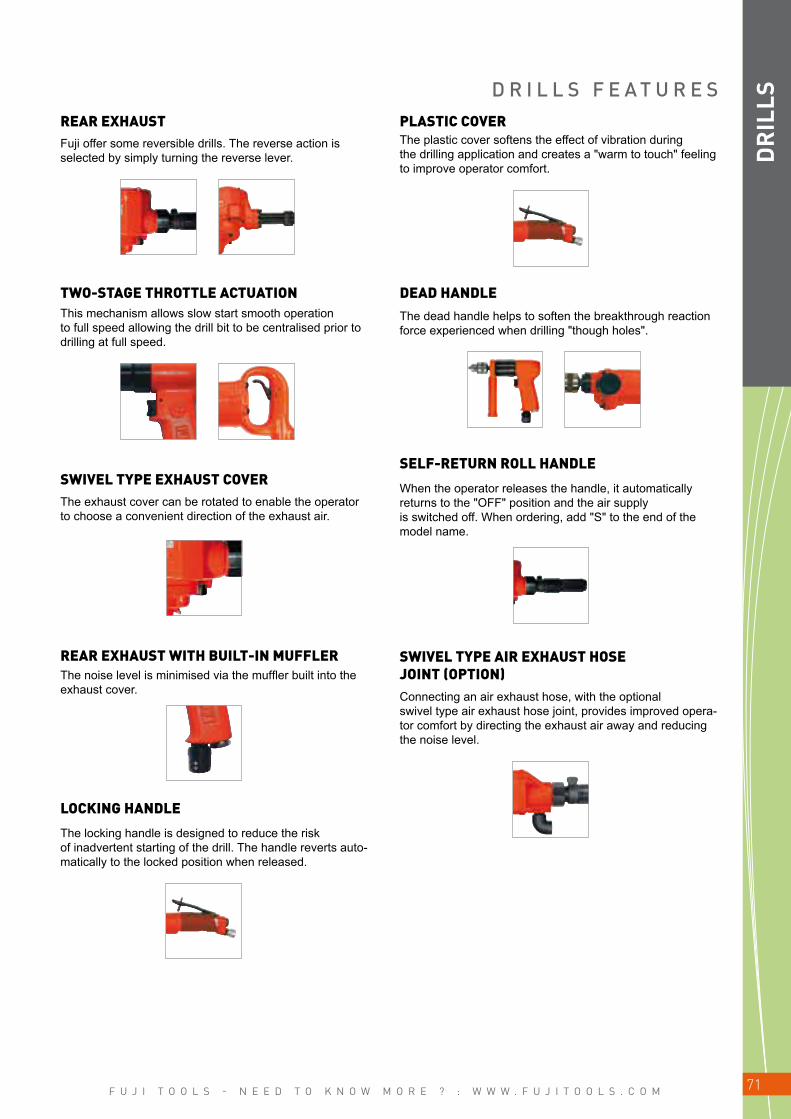
F U J I T O O L S - N E E D T O K N O W M O R E ? : W W W . F U J I T O O L S . C O M 71
DR
ILLSD R I L L S F E A T U R E S
REAR EXHAUST
TWO-STAGE THROTTLE ACTUATION
SWIVEL TYPE EXHAUST COVER
REAR EXHAUST WITH BUILT-IN MUFFLER
LOCKING HANDLE
PLASTIC COVER
DEAD HANDLE
SELF-RETURN ROLL HANDLE
SWIVEL TYPE AIR EXHAUST HOSE JOINT (OPTION)
Fuji offer some reversible drills. The reverse action is selected by simply turning the reverse lever.
This mechanism allows slow start smooth operation to full speed allowing the drill bit to be centralised prior to drilling at full speed.
The exhaust cover can be rotated to enable the operator to choose a convenient direction of the exhaust air.
The noise level is minimised via the muffler built into the exhaust cover.
The locking handle is designed to reduce the risk of inadvertent starting of the drill. The handle reverts auto-matically to the locked position when released.
The plastic cover softens the effect of vibration during the drilling application and creates a "warm to touch" feeling to improve operator comfort.
The dead handle helps to soften the breakthrough reaction force experienced when drilling "though holes".
When the operator releases the handle, it automatically returns to the "OFF" position and the air supply is switched off. When ordering, add "S" to the end of the model name.
Connecting an air exhaust hose, with the optional swivel type air exhaust hose joint, provides improved opera-tor comfort by directing the exhaust air away and reducing the noise level.

F U J I T O O L S - N E E D T O K N O W M O R E ? : W W W . F U J I T O O L S . C O M72
FRD-5S
FRD-6S
FRD-8PXFRD-6PH-3 FRD-6PH-7
DR
ILLS
Model Drilling Capacity Stall Torque Free
SpeedType and Size
of SpindleChuck
CapacitySide to Center Power Overall
Length Weight Max. Air Consumption Air Hose Size
Thread Type Taper type mm in N.m kgf.m ft.lb min-1 Thread Taper Thread Taper mm in W hp mm in kg lb m3/min ft3/min mm in
FRD-5S-1 5 3/16 0.2 0.20 0.15 3,200 3/8–24 – 6.5 – 18.5 47/64 180 0.24 175 6 57/64 0.6 1.3 0.60 21.2 6.35 1/4FRD-5S-2T 2 5/64 0.3 0.03 0.22 24,000 - J.T#D – 5.0 18.5 47/64 180 0.24 164 6 15/32 0.6 1.3 0.60 21.2 6.35 1/4FRD-6S-1T 3 1/4 0.6 0.06 0.44 21,000 - J.T#1 - 6.5 21.0 53/64 290 0.39 177 6 31/32 0.7 1.5 0.68 24.0 9.5 3/8
FRD-6S-2 5 3/16 2.5 0.25 1.84 4,300 3/8–24 – 6.5 – 21.0 53/64 290 0.39 209 8 15/64 0.9 1.9 0.68 24.0 9.5 3/8FRD-6S-3 8 5/16 2.9 0.30 2.13 2,800 3/8–24 – 8.0 – 21.0 53/64 290 0.39 212 8 23/64 1.0 2.2 0.68 24.0 9.5 3/8FRD-6S-5 10 7/16 6.9 0.70 5.08 1,300 3/8–24 – 10.0 – 23.0 29/32 290 0.39 233 9 3/16 1.0 2.2 0.68 24.0 9.5 3/8FRD-6S-7 13 1/2 15.7 1.60 11.6 600 1/2–20 13.0 21.0 53/64 290 0.39 261 10 9/32 1.5 3.3 0.68 24.0 9.5 3/8
Model Drilling Capacity Stall Torque Free
SpeedType and Size
of SpindleChuck
CapacitySide to Center Power Overall
Length Weight Max. Air Consumption Air Hose Size
Thread Type Taper type mm in N.m kgf.m ft.lb min-1 Thread Taper Thread Taper mm in W hp mm in kg lb m3/min ft3/min mm in
•FRD-5S-1F 5 3/16 2.0 0.20 1.4 3,200 3/8–24 – 6.5 – 18.5 47/64 180 0.24 175 6 57/64 0.6 1.3 0.60 21.2 6.35 1/4FRD-5S-2TF 2 5/64 0.3 0.03 0.2 24,000 – J.T#D – 5.0 18.5 47/64 180 0.24 164 6 15/32 0.6 1.3 0.60 21.2 6.35 1/4
•FRD-6S-2F 5 3/16 2.5 0.25 1.8 4,300 3/8–24 – 6.5 – 21.0 53/64 290 0.39 209 8 15/64 0.9 1.9 0.68 24.0 9.5 3/8•FRD-6S-3F 8 5/16 2.9 0.30 2.1 2,800 3/8–24 – 8.0 – 21.0 53/64 290 0.39 212 8 23/64 1.0 2.2 0.68 24.0 9.5 3/8•FRD-6S-5F 10 7/16 6.9 0.70 5.0 1,300 3/8–24 – 10.0 – 23.0 29/32 290 0.39 233 9 3/16 1.0 2.2 0.68 24.0 9.5 3/8•FRD-6S-7F 13 1/2 15.7 1.60 11.5 600 1/2–20 – 13.0 – 21.0 53/64 290 0.39 261 10 9/32 1.5 3.3 0.68 24.0 9.5 3/8
Model Drilling Capacity Stall Torque Free
SpeedType and Size
of SpindleChuck
CapacitySide to Center Power Overall
Length Weight Max. Air Consumption Air Hose Size
Thread Type Taper type mm in N.m kgf.m ft.lb min-1 Thread Taper Thread Taper mm in W hp mm in kg lb m3/min ft3/min mm in
•FRD-5P-1 5 3/16 2.0 0.20 1.4 3,200 3/8–24 – 6.5 – 18.0 45/64 180 0.24 155 6 7/64 0.6 1.3 0.40 14.1 6.35 1/4FRD-6PX-1T 3 1/8 0.6 0.06 0.44 21,000 – JT#1 6.5 21.0 0 53/64 290 0.39 182 7 11/64 1.0 2.2 0.55 19.2 9.5 3/8FRD-6PH-2 5 3/16 2.7 0.27 1.98 4,300 – JT#1 6.5 21.0 0 53/64 340 0.46 198 7 51/64 0.9 2.0 0.59 20.6 9.5 3/8FRD-6PH-3 6.5 1/4 4.3 0.43 3.17 2,800 – JT#1 6.5 21.0 0 53/64 340 0.46 198 7 51/64 0.9 2.0 0.59 20.6 9.5 3/8FRD-6PH-3(8) 8 5/16 4.3 0.43 3.17 2,800 – JT#1 8 21.0 0 53/64 340 0.46 205 8 5/64 1.0 2.2 0.59 20.6 9.5 3/8FRD-6PH-5 10 7/16 7.5 0.75 5.53 1,300 – JT#2S 10 21.0 0 53/64 320 0.43 243 9 9/16 1.4 3.1 0.59 20.6 9.5 3/8FRD-6PH-7 13 1/2 15.8 0.16 11.6 600 – JT#6 13 22.5 0 57/64 320 0.43 258 10 5/32 1.5 3.3 0.59 20.6 9.5 3/8
•FRD-8PX-1 8 5/16 5.9 0.60 4.3 2,600 3/8–24 – 8.0 – 25.0 63/64 440 0.59 187 7 3/8 1.5 3.3 0.76 26.8 9.5 3/8•FRD-8PX-2 10 7/16 11.8 1.20 8.6 1,300 3/8–24 – 10.0 – 26.5 1 3/64 440 0.59 210 8 9/32 1.9 4.2 0.76 26.8 9.5 3/8•FRD-8PX-3 13 1/2 16.7 1.70 12.3 900 1/2–20 – 13.0 – 25.5 1 440 0.59 240 9 29/64 2.5 5.5 0.76 26.8 9.5 3/8
PISTOL/REAR EXHAUST TYPE
Air Inlet Thread Size: PT or NPT 1/4"*Marked • are furnished with Dead Handle.
N° Models Type and Size of Spindle Chuck CapacityDCK-5J FRD-5S-2T, 2TF J.T.#D(Taper) 5mmDCK-6.5 FRD-5S-1, 1F, 6S-2, 2F, 5P-1, 6PX-2 3/8-24(Thread) 6.5mmDCK-8 FRD-6S-3, 3F, 6PX-3, 8PX-1 3/8-24(Thread) 8mmDCK-10 FRD-6S-5, 5F, 6PX-5, 8PX-2 3/8-24(Thread) 10mmDCK-13 FRD-6S-7, 7F, 6PX-7, 8PX-3, 12Z-1, 1C 1/2-20(Thread) 13mmDCK-16 FRD-16Z-1, 1C 5/8-16(Thread) 16mm
D R I L L S
Fuji Drills are light weight with a sturdy construction. Their practical design represents Fuji's latest developments in drills tech-nology. Fuji offers a complete line of drills with a drilling capacity range from 2 mm to 100 mm.
STRAIGHT/SIDE EXHAUST TYPE (NOT AVAILABLE FOR CE AND ANSI/NA MARKETS)
LOCKING STRAIGHT/SIDE EXHAUST TYPE
Air Inlet Thread Size: PT or NPT 1/4"*Marked • are furnished with Dead Handle.
DRILL CHUCKS
Air Inlet Thread Size: PT or NPT 1/4"
ACCESSORIES
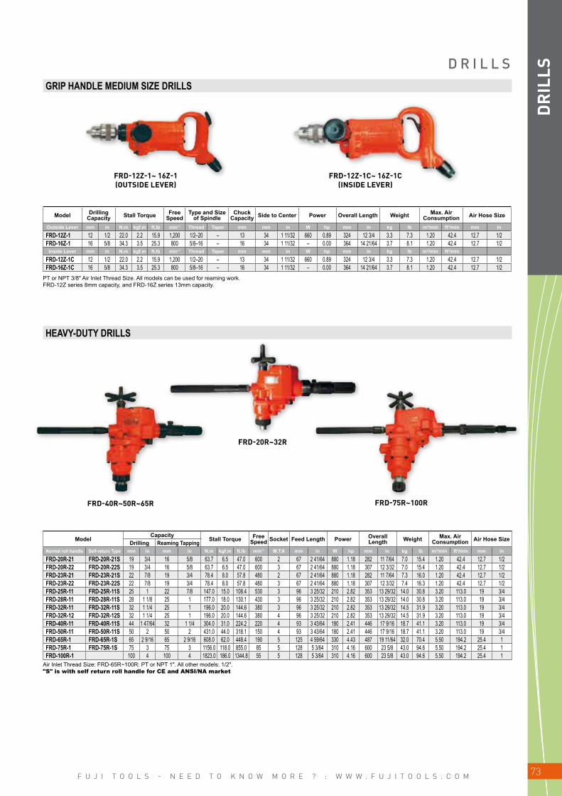
F U J I T O O L S - N E E D T O K N O W M O R E ? : W W W . F U J I T O O L S . C O M 73
FRD-40R~50R~65R
FRD-20R~32R
FRD-75R~100R
DR
ILLS
FRD-12Z-1C~ 16Z-1C(INSIDE LEVER)
FRD-12Z-1~ 16Z-1(OUTSIDE LEVER)
GRIP HANDLE MEDIUM SIZE DRILLS
HEAVY-DUTY DRILLS
Model Drilling Capacity Stall Torque Free
SpeedType and Size
of SpindleChuck
Capacity Side to Center Power Overall Length Weight Max. Air Consumption Air Hose Size
Outside Lever mm in N.m kgf.m ft.lb min-1 Thread Taper mm mm in W hp mm in kg lb m3/min ft3/min mm in
FRD-12Z-1 12 1/2 22.0 2.2 15.9 1,200 1/2–20 – 13 34 1 11/32 660 0.89 324 12 3/4 3.3 7.3 1.20 42.4 12.7 1/2FRD-16Z-1 16 5/8 34.3 3.5 25.3 800 5/8–16 – 16 34 1 11/32 – 0.00 364 14 21/64 3.7 8.1 1.20 42.4 12.7 1/2
Inside Lever mm in N.m kgf.m ft.lb min-1 Thread Taper mm mm in W hp mm in kg lb m3/min ft3/min
FRD-12Z-1C 12 1/2 22.0 2.2 15.9 1,200 1/2–20 – 13 34 1 11/32 660 0.89 324 12 3/4 3.3 7.3 1.20 42.4 12.7 1/2FRD-16Z-1C 16 5/8 34.3 3.5 25.3 800 5/8–16 – 16 34 1 11/32 – 0.00 364 14 21/64 3.7 8.1 1.20 42.4 12.7 1/2
PT or NPT 3/8" Air Inlet Thread Size. All models can be used for reaming work.FRD-12Z series 8mm capacity, and FRD-16Z series 13mm capacity.
ModelCapacity
Stall Torque Free Speed Socket Feed Length Power Overall
Length Weight Max. Air Consumption Air Hose SizeDrilling Reaming Tapping
Normal roll handle Self-return Type mm in mm in N.m kgf.m ft.lb min-1 M.T.# mm in W hp mm in kg lb m3/min ft3/min mm in
FRD-20R-21 FRD-20R-21S 19 3/4 16 5/8 63.7 6.5 47.0 600 2 67 2 41/64 880 1.18 282 11 7/64 7.0 15.4 1.20 42.4 12.7 1/2FRD-20R-22 FRD-20R-22S 19 3/4 16 5/8 63.7 6.5 47.0 600 3 67 2 41/64 880 1.18 307 12 3/32 7.0 15.4 1.20 42.4 12.7 1/2FRD-23R-21 FRD-23R-21S 22 7/8 19 3/4 78.4 8.0 57.8 480 2 67 2 41/64 880 1.18 282 11 7/64 7.3 16.0 1.20 42.4 12.7 1/2FRD-23R-22 FRD-23R-22S 22 7/8 19 3/4 78.4 8.0 57.8 480 3 67 2 41/64 880 1.18 307 12 3/32 7.4 16.3 1.20 42.4 12.7 1/2FRD-25R-11 FRD-25R-11S 25 1 22 7/8 147.0 15.0 108.4 530 3 96 3 25/32 210 2.82 353 13 29/32 14.0 30.8 3.20 113.0 19 3/4FRD-28R-11 FRD-28R-11S 28 1 1/8 25 1 177.0 18.0 130.1 430 3 96 3 25/32 210 2.82 353 13 29/32 14.0 30.8 3.20 113.0 19 3/4FRD-32R-11 FRD-32R-11S 32 1 1/4 25 1 196.0 20.0 144.6 380 3 96 3 25/32 210 2.82 353 13 29/32 14.5 31.9 3.20 113.0 19 3/4FRD-32R-12 FRD-32R-12S 32 1 1/4 25 1 196.0 20.0 144.6 380 4 96 3 25/32 210 2.82 353 13 29/32 14.5 31.9 3.20 113.0 19 3/4FRD-40R-11 FRD-40R-11S 44 1 47/64 32 1 1/4 304.0 31.0 224.2 220 4 93 3 43/64 180 2.41 446 17 9/16 18.7 41.1 3.20 113.0 19 3/4FRD-50R-11 FRD-50R-11S 50 2 50 2 431.0 44.0 318.1 150 4 93 3 43/64 180 2.41 446 17 9/16 18.7 41.1 3.20 113.0 19 3/4FRD-65R-1 FRD-65R-1S 65 2 9/16 65 2 9/16 608.0 62.0 448.4 190 5 125 4 59/64 330 4.43 487 19 11/64 32.0 70.4 5.50 194.2 25.4 1FRD-75R-1 FRD-75R-1S 75 3 75 3 1156.0 118.0 855.0 85 5 128 5 3/64 310 4.16 600 23 5/8 43.0 94.6 5.50 194.2 25.4 1FRD-100R-1 100 4 100 4 1823.0 186.0 1344.8 55 5 128 5 3/64 310 4.16 600 23 5/8 43.0 94.6 5.50 194.2 25.4 1
Air Inlet Thread Size: FRD-65R~100R: PT or NPT 1". All other models: 1/2"."S" is with self return roll handle for CE and ANSI/NA market
D R I L L S

F U J I T O O L S - N E E D T O K N O W M O R E ? : W W W . F U J I T O O L S . C O M74
FCD-6A-1
FCD-6EX-3
FCD-6B-1
FCD-6EX-4
FCD-6X-1, 2 FCD-10X-1
FCD-6B-1F
FCD-10X-1FFCD-6X-1F, 2F
DR
ILLS
SNAKE DRILLS(SN-2~6)
DRILL CHUCKS(CN-1802~1807)
*PT or NPT 1/4" Air Inlet Thread Size, All models are Rear Exhaust types.
*PT or NPT 1/4" Air Inlet Thread Size, All models are Rear Exhaust types.
B A B Y A N G L E D R I L L S
Fuji Baby Angle Drills are equipped with a compact head (low height and side-to-center head dimensions) to allow these tools to be used in confined areas. Ball and needle bearings used throughout angle heads provide long service life and less spindle run-out.
Snake Drill Bits 2mm to 6mm and Drill Chuck capacities1/16" to 1/4" are available on request
Thread1/4–28
Thread1/4–28
ModelDrilling
Capacity (Guidance)
Stall Torque Free Speed
Spindle Thread Size Side to Center Power Overall Length Weight Max. Air
Consumption Air Hose Size
mm in N.m kgf.m ft.lb min-1 in mm in W hp mm in kg lb m3/min ft3/min mm in
Front Exhaust TypeFCD-6A-1 6 1/4 2.5 0.25 1.8 2,500 1/4–28UNF 9.5 3/8 160 0.21 223 8 49/64 0.60 1.3 0.56 19.8 6.3 1/4FCD-6B-1 6 1/4 2.5 0.25 1.8 2,500 1/4–28UNF 9.5 3/8 160 0.21 222 8 47/64 0.60 1.3 0.56 19.8 6.3 1/4Rear Exhaust TypeFCD-6EX-3 6 1/4 2.9 0.30 2.2 3,500 1/4–28UNF 8.5 11/32 290 0.39 246 9 11/16 0.69 1.5 0.76 26.9 6.3 1/4FCD-6EX-4 6 1/4 2.9 0.30 2.2 3,500 1/4–28UNF 8.5 11/32 290 0.39 246 9 11/16 0.69 1.5 0.76 26.9 6.3 1/4
ModelDrilling
Capacity (Guidance)
Stall Torque Free Speed Spindle Thread Size Side to Center Power Overall Length Weight Max. Air
ConsumptionAir Hose
Sizemm in N.m kgf.m ft.lb min-1 in mm in W hp mm in kg lb m3/min ft3/min mm in
Front Exhaust TypeFCD-6B-1F 6 1/4 2.5 0.25 1.8 2,500 1/4–28UNF 9.5 3/8 160 0.21 222 8 47/64 0.60 1.3 0.56 19.8 6.3 1/4
CORNER DRILLS (NOT AVAILABLE FOR CE AND ANSI/NA MARKETS)
BABY ANGLE DRILLS (NOT AVAILABLE FOR CE AND ANSI/NA MARKETS)
LOCKING LEVER BABY ANGLE DRILLS
LOCKING LEVER CORNER DRILLS
Fuji utilizes their power transmission knowledge in their line of corner drills. In addition to their power, these drills are designed to work well in confined spaces.
ModelDrilling
Capacity (Guidance)
Stall Torque Free Speed
Spindle Thread Size
Chuck Capacity Side to Center Power Overall Length Weight Max. Air
ConsumptionAir Hose
Sizemm in N.m kgf.m ft.lb min-1 in mm mm in W hp mm in kg lb m3/min ft3/min mm in
FCD-6X-1 6 1/4 4.9 0.50 3.6 2,500 3/8–24UNF 6.5 21 53/64 340 0.46 267 10 33/64 1.7 3.7 0.68 24.0 9.5 3/8 FCD-6X-2 8 5/16 7.8 0.80 5.7 1,500 3/8–24UNF 8.0 21 53/64 290 0.39 281 11 1/16 1.9 4.1 0.68 24.0 9.5 3/8 FCD-10X-1 10 7/16 11.8 1.20 8.6 1,200 1/2–20UNF 10.0 21 53/64 420 0.56 377 14 27/32 2.2 4.8 0.50 17.6 9.5 3/8
ModelDrilling
Capacity (Guidance)
Stall Torque Free Speed
Spindle Thread Size
Chuck Capacity Side to Center Power Overall Length Weight Max. Air
ConsumptionAir Hose
Sizemm in N.m kgf.m ft.lb min-1 in mm mm in W hp mm in kg lb m3/min ft3/min mm in
FCD-6X-1F 6 1/4 4.9 0.50 3.6 2,500 3/8–24UNF 6.5 21 53/64 340 0.46 267 10 33/64 1.7 3.7 0.68 24.0 9.5 3/8 FCD-6X-2F 8 5/16 7.8 0.80 5.7 1,500 3/8–24UNF 8.0 21 53/64 290 0.39 281 11 1/16 1.9 4.1 0.68 24.0 9.5 3/8 FCD-10X-1F 10 7/16 11.8 1.20 8.6 1,200 1/2–20UNF 10.0 21 53/64 420 0.56 377 14 27/32 2.2 4.8 0.50 17.6 9.5 3/8
Air Inlet Thread Size: PT or NPT 1/4"
Air Inlet Thread Size: PT or NPT 1/4

F U J I T O O L S - N E E D T O K N O W M O R E ? : W W W . F U J I T O O L S . C O M 75
F-14CN.S F-22RCN.S
F-32RCN, 32RCNS
F-22RCR.S
FCD-23R~50R.S
F-32RCR.S
FCD-75R, 100R.SD
RIL
LS
Air Inlet Size: F-14CN series: PT or NPT 3/8", All others: 1/2"."S" is with self return roll handle for CE and ANSI/NA market
Air Inlet Thread Size: PT or NPT 1/2"."S" is with self return roll handle for CE and ANSI/NA market
HEAVY-DUTY CORNER DRILLS (NON-REVERSIBLE)
C O R N E R D R I L L S
ModelDrilling Capacity
Stall Torque Free Speed Socket Side to
CenterFeed
Length Power Overall Length Weight Max. Air
Consumption Air Hose SizeDrilling Reaming TappingNormal roll handle Self-return Type mm in mm in N.m kgf.m ft.lb min-1 M.T.# mm in mm in W hp mm in kg lb m3/min ft3/min mm in
F-14CN F-14CN-1S 14 9/16 9.5 3/8 31.4 3.2 23.1 1,000 1 24 15/16 38 1 1/2 700 0.94 410 16 9/64 4.6 10.1 1.25 44.1 12.7 1/2F-14CN-2 F-14CN-2S 14 9/16 9.5 3/8 31.4 3.2 23.1 1,000 2 24 15/16 38 1 1/2 700 0.94 410 16 9/64 4.6 10.1 1.25 44.1 12.7 1/2F-22RCN F-22RCN-1S 22 7/8 19.0 3/4 108.0 11.0 79.5 450 2 35 1 3/8 60 2 3/8 1100 1.48 493 19 13/32 8.5 18.7 1.50 53.0 12.7 1/2F-32RCN F-32RCN-1S 32 1 1/4 25.0 1 127.0 13.0 94.0 400 3 40 1 37/64 60 2 3/8 1320 1.77 523 20 19/32 9.7 21.3 1.50 53.0 12.7 1/2F-32RCNS F-32RCNS-1S 32 1 1/4 25.0 1 127.0 13.0 94.0 400 3 40 1 37/64 25 1 1320 1.77 529 20 53/64 8.8 19.3 1.50 53.0 12.7 1/2
ModelDrilling Capacity
Stall Torque Free Speed Socket Side to
CenterFeed
Length Power Overall Length Weight Max. Air
ConsumptionAir Hose
SizeDrilling Reaming TappingNormal roll handle Self-return Type mm in mm in N.m kgf.m ft.lb min-1 M.T.# mm in mm in W hp mm in kg lb m3/min ft3/min mm in
F-22RCR F-22RCR-1S 22 7/8 19.0 3/4 93.2 9.5 68.7 400 2 35 1 3/8 60 2 3/8 900 1.21 505 19 7/8 8.5 18.7 1.50 53.0 12.7 1/2F-32RCR F-32RCR-1S 32 1 1/4 25.0 1 113.0 11.5 83.1 315 3 40 1 37/64 60 2 3/8 810 1.09 538 21 3/16 10.0 22.0 1.50 53.0 12.7 1/2FCD-23R-11 FCD-23R-11S 22 7/8 19.0 3/4 80.4 8.2 59.3 430 2 27 1 1/16 35 1 3/8 900 1.21 472 18 37/64 7.0 15.4 1.50 53.0 12.7 1/2FCD-23R-12 FCD-23R-12S 22 7/8 19.0 3/4 80.4 8.2 59.3 430 3 27 1 1/16 35 1 3/8 900 1.21 472 18 37/64 7.1 15.6 1.50 53.0 12.7 1/2FCD-32R-11 FCD-32R-11S 32 1 1/4 32.0 1 1/4 177.0 18.0 130.1 350 3 35 1 3/8 53 22 3/4 1600 2.15 578 22 3/4 13.5 29.7 1.80 63.5 12.7 1/2FCD-50R-11 FCD-50R-11S 50 2 50.0 2 392.0 40.0 289.0 140 4 41 1 5/8 58 2 5/16 1600 2.15 595 23 27/64 16.0 35.2 2.25 79.4 19 3/4FCD-75R-11 FCD-75R-11S 75 3 75.0 3 834.0 85.0 614.8 85 5 49 1 15/16 57 2 1/4 1900 2.55 651 25 5/8 20.5 45.1 2.50 88.3 19 3/4FCD-100R-11 FCD-100R-11S 100 4 100.0 4 1370.0 140.0 1012.6 40 5 62 2 7/16 105 4 1/8 1900 2.55 730 28 3/4 29.3 64.4 2.25 79.4 19 3/4
HEAVY-DUTY CORNER DRILLS (REVERSIBLE)
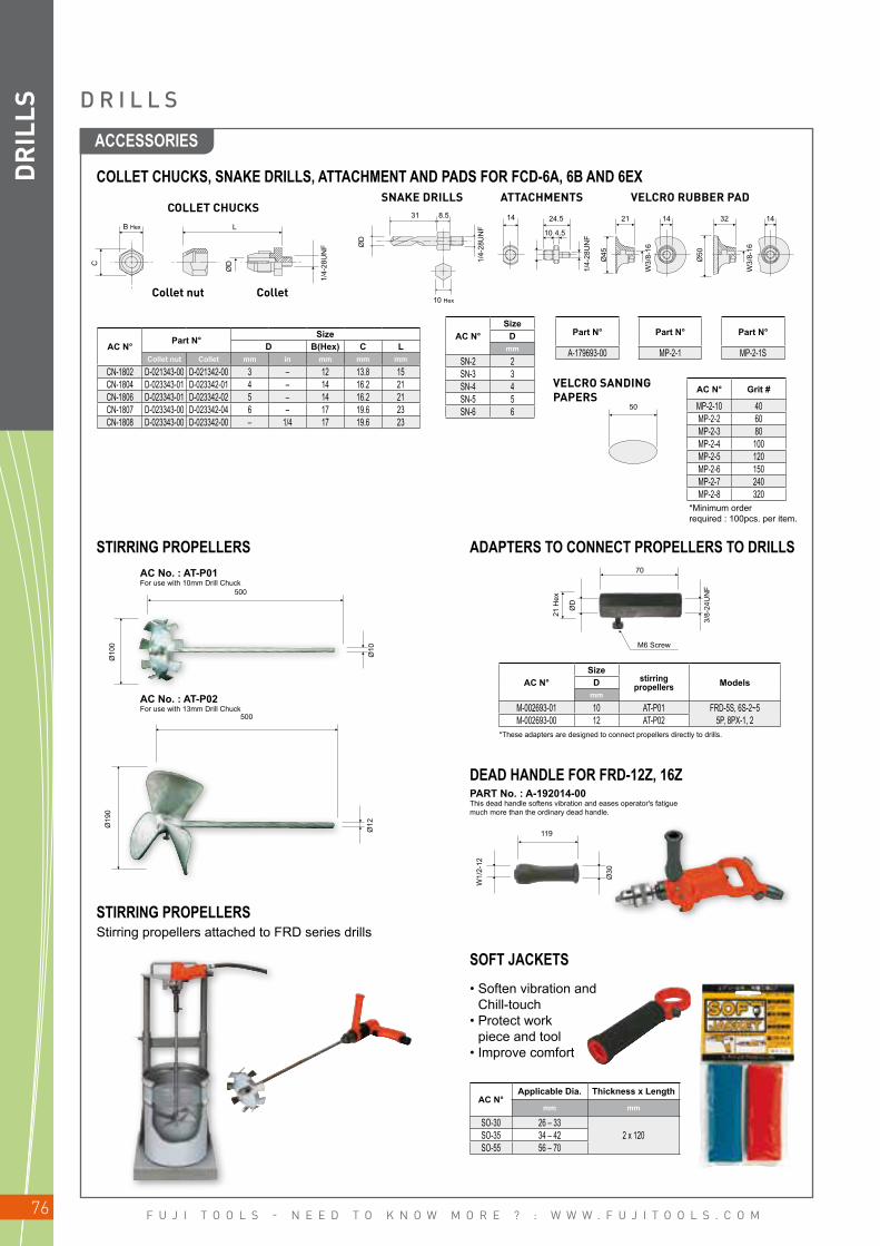
F U J I T O O L S - N E E D T O K N O W M O R E ? : W W W . F U J I T O O L S . C O M76
50
31 148.5
1/4-
28U
NF
ØD
1/4-
28U
NF
ØDC
B Hex L
10 Hex
24.5
4.510
Ø45
1/4-
28U
NF
W3/
8-16
Ø50
W3/
8-16
14321421
500
Ø10
Ø10
0
500
Ø19
0
Ø12
ØD
M6 Screw
70
21 H
ex
3/8-
24U
NF
W1/
2-12
119
Ø30
DR
ILLS
COLLET CHUCKS
Collet nut Collet
SNAKE DRILLS
VELCRO SANDING PAPERS
ATTACHMENTS VELCRO RUBBER PAD
AC No. : AT-P01For use with 10mm Drill Chuck
AC No. : AT-P02For use with 13mm Drill Chuck
AC N°Part N°
SizeD B(Hex) C L
Collet nut Collet mm in mm mm mm
CN-1802 D-021343-00 D-021342-00 3 – 12 13.8 15CN-1804 D-023343-01 D-023342-01 4 – 14 16.2 21CN-1806 D-023343-01 D-023342-02 5 – 14 16.2 21CN-1807 D-023343-00 D-023342-04 6 – 17 19.6 23CN-1808 D-023343-00 D-023342-00 – 1/4 17 19.6 23
AC N°Size
stirring propellers ModelsD
mm
M-002693-01 10 AT-P01 FRD-5S, 6S-2~55P, 8PX-1, 2M-002693-00 12 AT-P02
AC N°Size
Dmm
SN-2 2SN-3 3SN-4 4SN-5 5SN-6 6
Part N°
A-179693-00
Part N°
MP-2-1
Part N°
MP-2-1S
AC N° Grit #
MP-2-10 40MP-2-2 60MP-2-3 80MP-2-4 100MP-2-5 120MP-2-6 150MP-2-7 240MP-2-8 320
STIRRING PROPELLERS
STIRRING PROPELLERS
DEAD HANDLE FOR FRD-12Z, 16Z
AC N°Applicable Dia. Thickness x Length
mm mm
SO-30 26 – 332 x 120SO-35 34 – 42
SO-55 56 – 70
ADAPTERS TO CONNECT PROPELLERS TO DRILLS
Stirring propellers attached to FRD series drills
• Soften vibration and Chill-touch
• Protect work piece and tool
• Improve comfort
PART No. : A-192014-00This dead handle softens vibration and eases operator's fatigue much more than the ordinary dead handle.
*These adapters are designed to connect propellers directly to drills.
SOFT JACKETS
ACCESSORIES
D R I L L S
COLLET CHUCKS, SNAKE DRILLS, ATTACHMENT AND PADS FOR FCD-6A, 6B AND 6EX
*Minimum order required : 100pcs. per item.

F U J I T O O L S - N E E D T O K N O W M O R E ? : W W W . F U J I T O O L S . C O M 77
L
L
R
R
R L
A B C
T A P P E R S F E A T U R E SREVERSING
TWO-STAGE THROTTLING
AIR REGULATOR
DEAD HANDLE
REAR EXHAUST WITH AIR EXHAUST HOSE
REAR EXHAUST WITH BUILT-IN MUFFLER
UNIVERSAL TAPPING CHUCK
DRILL CHUCKS
A. Twin lever type-one lever for forward rotation (with throttle actuation) and one lever for reverse rotation (with throttle actuation).
B. See-saw type lever for throttle actuation and reversing.C. Push/Pull type-forward rotation when the tool is pushed
into the work-piece, reverse rotation when the tool is pulled away from the work-piece.
This mechanism allows a "slow start" to ensure tap is correctly aligned prior to actuating "full speed".
A 4 click stop regulator is built in and the operator can regu-late air supply for torque adjustment.
The dead handle is used to reduce the effect of "snatching" when tapping a through hole. It is also used when tapping "high torque" threads.
Connecting an air exhaust hose, provides improved operator comfort by directing the exhaust air away and reducing the noise level.
The noise level is minimised via the muffler built into the exhaust cover.
The universal tapping chuck provides optimal grip of the tap during the tapping operation.
A drill chuck can also be used for tapping where appropriate.
Push Pull
TAPP
ERS
F U J I T O O L S - N E E D T O K N O W M O R E ? : W W W . F U J I T O O L S . C O M78
FT-6P-1
FT-8PX-1 FT-13Z-1
FT-6BX-1(DRILL CHUCK TYPE)
FT-6BX-1(UNIVERSAL TAPPING
CHUCK TYPE)
ModelType
Tapping Capacity (Guidance) Free Speed (min-1)
Type and Size of Spindle Chuck Capacity Overall
Length Weight Max. Air Consumption Air Hose SizeSteel Aluminum
mm in mm in R L Tapper # M.T.# mm in kg lb m3/min ft3/min mm in
FT-6P-1 - 6 1/4 8 5/16 1,000 1,000 J.T.#1 8 236 9 19/64 1.8 4.0 0.50 17.7 9.5 3/8FT-6BX-1 D 6 1/4 8 5/16 2,000 2,000 J.T.#1 6.5 205 8 7/64 1.3 2.9 0.56 19.8 8.0 5/16 FT-6BX-1 T 6 1/4 8 5/16 2,000 2,000 J.T.#1 8 240 9 29/64 1.3 2.9 0.56 19.8 8.0 5/16 FT-8PX-1 - 8 5/16 10 3/8 450 450 M.T.#1 9 232 9 9/64 2.0 4.4 0.50 17.7 9.5 3/8 FT-13Z-1 - 13 1/2 – – 400 480 J.T.#6 13 384 15 1/8 4.0 8.8 1.25 44.1 12.7 1/2
N° Models Type and Size of SpindleTaper # Chuck Capacity
TCK-6 FT-6BX-1T J.T.#1 8mmTCK-8F FT-8PX-1 M.T.#1 9mmTCK-13-1 FT-13Z-1 J.T.#6 13mm
N° Models Type and Size of SpindleTaper # Chuck Capacity
DCK-6.5J FT-6BX-1(D Type) J.T.#1 6.5mmDCK-8J FT-6P-1 J.T.#1 8mm
*FT-6P-1, 6BX-1, 8PX-1: Air Inlet Thread Size: PT or NPT 1/4" *FT-13Z-1: Air Inlet Thread Size: PT or NPT 3/8" TYPE: D...Drill Chuck, T...Tapping Chuck.
TAPPING CHUCKS
DRILL CHUCKS
T A P P E R SEasy to use throttle and reversing trigger combined with a universal tapping chuck provide a smooth tapping operation. Fuji Tappers are available in tapping capacities from 6mm to 13mm.
ACCESSORIES
TAPP
ERS

F U J I T O O L S - N E E D T O K N O W M O R E ? : W W W . F U J I T O O L S . C O M 79
PERCUSSIVE TOOLS
PERCUSSIVE TOOLS FEATURES _____________________________________ 80
FLUX CHIPPERS / LIGHT HAMMERS ______________________________ 82
CHIPPING & CALKING HAMMERS / NEEDLE SCALERS __ 83
SCALING HAMMERS / SAND RAMMERS ________________________ 84
ACCESSORIES ____________________________________________________________________ 85

F U J I T O O L S - N E E D T O K N O W M O R E ? : W W W . F U J I T O O L S . C O M80
A B1
2
PER
CUSS
IVE
TOO
LS P E R C U S S I V E T O O L S F E A T U R E SVALVE MECHANISM
LOW AIR CONSUMPTION
QUICK CHANGE ATTACHMENTS FOR PERCUSSIVE TOOLS
MULTI-NEEDLES
PLASTIC HANDLE COVER
Equipped with following valve mechanism, Fuji Percussion Tools have trouble-free long life.
A. PLATE VALVEPlate valve consists of four parts of valve sheet, valve cover, valve case and valve. This simple mechanism and plate valve surface provide longer durability.FR Series
B. SLEEVE VALVEHollow valve enables a light and compact body and longer strokefor its size.
C. PISTON VALVEHigh blow frequency (60Hz to 90Hz) can be maintained as this piston functions as a valve providing high working efficiency.
Low air consumption 0.14-0.18 m3/min (due to the valve mechanism) enables Fuji Percussion Tools to be used with a smaller compressor.
A
B
C
Attachment, such as chisels and needles, can be quickly and easily changed.
Fuji Needle Scalers utilise multiple needles that do not contaminate the workpiece.
The plastic handle cover reduces the effect of vibration and provides an insulated grip for the operator.
SCALING HEADS
LOCKING HANDLE
TUNGSTEN CARBIDE TIPPED PISTON (OPTION)
LOW BLOW FREQUENCY
Three models are available to suit different applications- single head, dual head and triple head.
The locking handle are designed to reduce the risk of acci-dental starting of the tools. The handle is automatically locked when the operator releases the handle.
4-point Tungsten Carbide Piston is available on request for heavy removal operations.
The built-in Sleeve Valve allows the operator to adjust the blow frequency by adjusting the throttle valve.
A. Locking Roll Handle : FS-2AB. Locking Locking Lever Handle : FS, FR, FCH, FNS Series

F U J I T O O L S - N E E D T O K N O W M O R E ? : W W W . F U J I T O O L S . C O M 81
A B
PER
CUSS
IVE
TOO
LSP E R C U S S I V E T O O L S F E A T U R E SCHISEL RETAINER CHISEL HOLDER
A. Holder Spring (Bee-Hive Retainer)B. Holder Spring (B) (Quick Change Retainer)
Fuji Chipping and Calking Hammers are supplied with a chisel retainer as standard. This reduces the risk of the chisel relea-sing during operation.

F U J I T O O L S - N E E D T O K N O W M O R E ? : W W W . F U J I T O O L S . C O M82
FCH-20 FCH-20F
FCH-25
FCH-25-1F
FRH-3 FRH-6 FRH-6A
PER
CUSS
IVE
TOO
LS
FCH-25B-1F (SEPARATE BLOW TYPE)
FCH-25B (SEPARATE BLOW TYPE)
P E R C U S S I V E T O O L SFuji offers 3 variants of flux chippers with different removal rates.They are ideal for various removal operations; light chipping, carving stone, scaling, removing paint, rust, weld flux and light fins from castings. FCH-25B offers a "blow" function which is ideal for blowing particles away from the work piece.
Model Blows Piston Diameter Stroke Overall Length Weight Air Consumption (at Load) Air Hose Size
Push Lever Hz mm in mm in mm in kg lb m3/min ft3/min mm in
FCH-20 90 20 25/32 16 5/8 176 6 13/64 0.8 1.8 0.14 4.9 6.3 1/4FCH-20F 90 20 25/32 16 5/8 182 7 5/32 1.0 2.2 0.14 4.9 9.5 3/8FCH-25 60 25 1 20 25/32 204 8 1/32 1.5 3.3 0.18 6.4 9.5 3/8FCH-25B 60 25 1 20 25/32 239 9 13/32 1.7 3.7 0.18 6.4 8.0 5/16
Model Blows Piston Diameter Stroke Overall Length Weight Air Consumption (at Load) Air Hose Size
Locking Lever Hz mm in mm in mm in kg lb m3/min ft3/min mm in
FCH-20-1F 90 20 25/32 16 5/8 176 6 13/64 0.8 1.8 0.14 4.9 6.3 1/4FCH-20F-1F 90 20 25/32 16 5/8 182 7 5/32 1.0 2.2 0.14 4.9 9.5 3/8FCH-25-1F 60 25 1 20 25/32 204 8 1/32 1.5 3.3 0.18 6.4 9.5 3/8FCH-25B-1F 60 25 1 20 25/32 239 9 13/32 1.7 3.7 0.18 6.4 8.0 5/16
Model Chisel Shank
Riveting Capacity (mm) Blows Piston Diameter Stroke Overall Length Weight Air Consumption
(at Load) Air Hose Size
Duralmin Steel Hz mm in mm in mm in kg lb m3/min ft3/min mm in
FRH-3-1 Hex 3.2 2.5 60 14.3 9/16 38.0 1 1/2 140 5 33/64 1.1 2.4 0.35 12.4 9.5 3/8FRH-3-2 Round 3.2 2.5 60 14.3 9/16 38.0 1 1/2 140 5 33/64 1.1 2.4 0.35 12.4 9.5 3/8FRH-6-1 Hex 6.4 5.0 30 12.7 1/2 100.0 4 206 8 7/64 1.4 3.0 0.35 12.4 9.5 3/8FRH-6-2 Round 6.4 5.0 30 12.7 1/2 100.0 4 206 8 7/64 1.4 3.0 0.35 12.4 9.5 3/8FRH-6A-1 Hex 6.4 5.0 50 20.0 25/32 44.5 1 3/4 193 7 19/32 1.5 3.3 0.40 14.1 9.5 3/8FRH-6A-2 Round 6.4 5.0 50 20.0 25/32 44.5 1 3/4 193 7 19/32 1.5 3.3 0.40 14.1 9.5 3/8
LIGHT HAMMERS
Fuji light hammers provide a controllable impact for rivetting to reduce the effect of work hardening of the rivet or damage to the surrounding metal. These tools are easily adapted to perform other operations, such as cutting, ripping, shearing, punching and gouging with suitable chisels fitted.
FRH-SERIES KIT
FRH-ModelAir RegulatorHose NippleHolder SpringHolder Spring (B)7 kinds of ChiselMetal Carrying Case
FLUX CHIPPERS (NOT AVAILABLE FOR CE AND ANSI/NA MARKETS)
LOCKING LEVER FLUX CHIPPERS
Air Inlet Thread Size: PT or NPT 1/4"
Air Inlet Thread Size: PT or NPT 1/4"
Air Inlet Thread Size: PT or NPT 1/4"

F U J I T O O L S - N E E D T O K N O W M O R E ? : W W W . F U J I T O O L S . C O M 83
FNS-2 FNS-2P
FNS-2-1F FNS-2P-1F
FC-01SA FC-01 FC-1Z~4Z
PER
CUSS
IVE
TOO
LS
CHIPPING & CALKING HAMMERS
NEEDLE SCALERS (NOT AVAILABLE FOR CE AND ANSI/NA MARKETS)
LOCKING LEVER NEEDLE SCALERS
Fuji chipping and calking hammers are durable. They are excellent for concrete, stone, weld flux removal.
ModelBlows Piston Diameter Stroke Chisel
Insert Overall Length Weight Air Consumption (at Load) Air Hose Size
Hz mm in mm in mm in mm in kg lb m3/min ft3/min mm mm
FC-01SA-H 50 20.0 25/32 44.5 1 3/4 12 x 45 273 10 3/4 2.5 5.5 0.42 14.8 9.5 3/8FC-01SA-R 50 20.0 25/32 44.5 1 3/4 14 x 45 273 10 3/4 2.5 5.5 0.42 14.8 9.5 3/8FC-01-3 50 20.0 25/32 44.5 1 3/4 12 x 45 273 10 3/4 2.6 5.7 0.42 14.8 9.5 3/8FC-01-4 50 20.0 25/32 44.5 1 3/4 14 x 45 273 10 3/4 2.6 5.7 0.42 14.8 9.5 3/8FC-1Z-1 50 28.5 1 1/8 25.0 1 14.8 x 60 301 11 27/32 5.0 11 0.60 21.2 12.7 1/2FC-1Z-2 50 28.5 1 1/8 25.0 1 17.5 x 60 301 11 27/32 5.0 11 0.60 21.2 12.7 1/2FC-2Z-1 42 28.5 1 1/8 51.0 2 14.8 x 60 342 13 15/32 5.7 12.5 0.60 21.2 12.7 1/2FC-2Z-2 42 28.5 1 1/8 51.0 2 17.5 x 60 342 13 15/32 5.7 12.5 0.60 21.2 12.7 1/2FC-3Z-1 38 28.5 1 1/8 76.0 3 14.8 x 60 386 15 13/64 6.3 13.8 0.65 22.9 12.7 1/2FC-3Z-2 38 28.5 1 1/8 76.0 3 17.5 x 60 386 15 13/64 6.3 13.8 0.65 22.9 12.7 1/2FC-4Z-1 28 28.5 1 1/8 102.0 4 14.8 x 60 425 16 47/64 6.8 14.9 0.65 22.9 12.7 1/2FC-4Z-2 28 28.5 1 1/8 102.0 4 17.5 x 60 425 16 47/64 6.8 14.9 0.65 22.9 12.7 1/2
P E R C U S S I V E T O O L S
Fuji needle scalers are useful for removing weld flux, sand from castings, scales from forgings, rust, paint, scales from ship hulls and finishing rough surfaces of rock or concrete. Fuji needle scalers feature a unique valve less design and work well on uneven or irregular surfaces.
MOVEMENT OF NEEDLES
Model Throttle Type
Blows Piston Diameter Needle Roller N° and Dia. of Needle Needle Stroke Overall Length Weight Air Consumption
(at Load) Air Hose Size
Locking Lever Hz mm in mm in 3 mm 2 mm mm in mm in kg lb m3/min ft3/min mm in
FNS-2-1F Straight 133 25 1 180 7 3/32 19 37 7 9/32 325 12 51/64 1.9 4.1 0.18 6.4 9.5 3/8FNS-2P-1F Pistol 133 25 1 180 7 3/32 19 37 7 9/32 371 14 39/64 2.5 5.5 0.18 6.4 9.5 3/8
Model Throttle Type
Blows Piston Diameter Needle Roller N° and Dia. of Needle Needle Stroke Overall Length Weight Air Consumption
(at Load)Air Hose
SizePush Lever Hz mm in mm in 3 mm 2 mm mm in mm in kg lb m3/min ft3/min mm in
FNS-2 Straight 133 25 1 180 7 3/32 19 37 7 9/32 325 12 51/64 1.9 4.1 0.18 6.4 9.5 3/8FNS-2P Pistol 133 25 1 180 7 3/32 19 37 7 9/32 371 14 39/64 2.5 5.5 0.18 6.4 9.5 3/8
*Specify needle diameter (3mm or 2mm) when ordering.
*Specify needle diameter (3mm or 2mm) when ordering.
Air Inlet Thread Size PT or NPT: 3/8" exept FC-01 serie 1/4"
Air Inlet Thread Size: PT or NPT 1/4"
Air Inlet Thread Size: PT or NPT 1/4"

F U J I T O O L S - N E E D T O K N O W M O R E ? : W W W . F U J I T O O L S . C O M84
FS-2A
FS-2A-1F
FR-18B~25B
FR-18L~32
FR-18B-2F~25B-2F FR-18L-2F~32-2F
PER
CUSS
IVE
TOO
LS
Model Blows Piston Diameter Stroke Butt Diameter Overall Length Weight Air Consumption (at Load) Air Hose Size
Locking Lever Hz mm in mm in mm in mm in kg lb m3/min ft3/min mm in
FR-18B-2F 30 18.0 45/64 50 1 31/32 41 1 5/8 280 (383) 11 1/32 (15 5/64) 1.5 3.3 0.40 14.1 9.5 3/8FR-22B-2F 17 22.0 55/64 64 2 33/64 51 2 1/32 350 (451) 13 25/32 (17 3/4) 3.0 6.6 0.50 17.7 9.5 3/8FR-25B-2F 13 25.4 1 83 3 17/64 67 2 41/64 506 (597) 19 59/64 (23 1/2) 5.5 12.1 0.70 24.7 12.7 1/2FR-18L-2F 30 18.0 45/64 50 1 31/32 41 1 5/8 558 (523) 21 31/32 (20 19/32) 2.0 4.4 0.40 14.1 9.5 3/8FR-22L-2F 17 22.0 55/64 64 2 33/64 51 2 1/32 633 (600) 24 59/64 (23 5/8) 3.3 7.2 0.50 17.7 9.5 3/8FR-25L-2F 13 25.4 1 83 3 17/64 67 2 41/64 1,043 (1,005) 41 1/16 (39 9/16) 6.0 13.2 0.70 24.7 12.7 1/2FR-32-2F 12 32.0 1 17/64 127 5 75 2 61/64 1,086 (1,090) 42 3/4 (42 29/32) 10.0 22.0 0.80 28.2 12.7 1/2
Model Blows Piston Diameter Stroke Butt Diameter Overall Length Weight Air Consumption (at Load) Air Hose Size
Push Lever Hz mm in mm in mm in mm in kg lb m3/min ft3/min mm in
FR-18B 30 18.0 45/64 50 1 31/32 41 1 5/8 280 (383) 11 1/32 (15 5/64) 1.5 3.3 0.40 14.1 9.5 3/8FR-22B 17 22.0 55/64 64 2 33/64 51 2 1/32 350 (451) 13 25/32 (17 3/4) 3.0 6.6 0.50 17.7 9.5 3/8FR-25B 13 25.4 1 83 3 17/64 67 2 41/64 506 (597) 19 59/64 (23 1/2) 5.5 12.1 0.70 24.7 12.7 1/2FR-18L 30 18.0 45/64 50 1 31/32 41 1 5/8 558 (523) 21 31/32 (20 19/32) 2.0 4.4 0.40 14.1 9.5 3/8FR-22L 17 22.0 55/64 64 2 33/64 51 2 1/32 633 (600) 24 59/64 (23 5/8) 3.3 7.2 0.50 17.7 9.5 3/8FR-25L 13 25.4 1 83 3 17/64 67 2 41/64 1,043 (1,005) 41 1/16 (39 9/16) 6.0 13.2 0.70 24.7 12.7 1/2FR-32 12 32.0 1 17/64 127 5 75 2 61/64 1,086 (1,090) 42 3/4 (42 29/32) 10.0 22.0 0.80 28.2 12.7 1/2
SAND RAMMERS (NOT AVAILABLE FOR CE AND ANSI/NA MARKETS)
LOCKING LEVER SAND RAMMERS
Fuji sand rammers are powerful but light with a stroke range from 50mm to 127mm. Fuji sand rammers are excellent for ramming sand for casting in any ferrous or non-ferrous foundry. Non-rotary type rammers are available for use with irregular shaped butts.
Model Number of Cylinder
Blows Piston Diameter Stroke Angle Height Overall Length Weight Air Consumption
(at Load) Air Hose Size
Hz mm in mm in mm in mm in kg lb m3/min ft3/min mm in
FS-2A 1 133 30 1 3/16 16 5/8 94 3 11/16 510 (537) 20 5/64 (21 9/64) 2.5 5.5 0.25 8.8 9.5 3/8
Model Number of Cylinder
Blows Piston Diameter Stroke Angle Height Overall Length Weight Air Consumption
(at Load) Air Hose Size
Hz mm in mm in mm in mm in kg lb m3/min ft3/min mm in
FS-2A-1F 1 133 30 1 3/16 16 5/8 94 3 11/16 510 (537) 20 5/64 (21 9/64) 2.5 5.5 0.25 8.8 9.5 3/8
Air Inlet Thread Size: PT or NPT 3/8"
Air Inlet Thread Size: PT or NPT 3/8"
SCALING HAMMERS (NOT AVAILABLE FOR CE AND ANSI/NA MARKETS)
LOCKING LEVER SCALING HAMMERS
Fuji offers 1, 2 and 3 head scaling hammers. These tools have proven to be very efficient in cleaning heavily oxidized surfaces which occur on ships' hulls, bridges and storage tanks.
P E R C U S S I V E T O O L S
Air Inlet thread size : PT 1/4" except FR-25B, FR-25L, FR-32: 3/8"
Air Inlet thread PT : 3/8" except FR-18B-2F, FR-18L-2F, FR22L-2F: 1/4"

F U J I T O O L S - N E E D T O K N O W M O R E ? : W W W . F U J I T O O L S . C O M 85
20
20 20 20
L
L
Ø12
Ø12
Ø15
Ø15
Ø11
Ø11
9
9
204
4
27 25
L L L
25 25 2536 36
38 453.6 3.625 25
36
253.6
Ø12
Ø12
Ø12
Ø9.53 Ø9.53 Ø9.53
12.7
12.7
15.5
25
12.7
� �
�
�
�
PER
CUSS
IVE
TOO
LS
Type AC N°Size
Lmm
Blank
G-1-1 125G-1-2 155G-1-3 200G-1-4 250G-1-5 300
Flat
G-2-1 130G-2-2 155G-2-3 200G-2-4 250G-2-5 300
Type AC N°Size
Lmm
Blank
F-1-1 140F-1-2 155F-1-3 200F-1-4 250F-1-5 300
Type AC N°Size
Lmm
Flat
F-2-2 155F-2-3 200F-2-4 250F-2-5 300F-2-7* 400
Type AC N°Size
Lmm
Flux
F-3-2 155F-3-3 200F-3-4 250F-3-5 300F-3-7 400
BUSHING CHISELS FOR FCH-20F, 25 AND 25B
CHISELS FOR FCH-20
BUSHING CHISELS FOR FCH-20
CHISELS FOR FCH-20F, 25 AND 25B
TIPPED CHISELS FOR FCH-20
Type AC N°Overall Length Remark
mm
Point S-1 120 StandardS-3 160 Small Point
Flat S-2 120 StandardS-4-1 160 Small Flat
AC N°Tip Size
Point I x w x L
TWH-0006 4 2.5 x 2.5 x 5
AC N°Tip Size
Point I x w x L
TWH-0007 4 6 x 6 x 12
TWH-0003 9 5 x 5 x 15
TWH-0002 16 4 x 4 x 16
TWH-0004 25 4.5 x 4.5 x 22.5
w
Ll
w
Ll
w
w
w
l
l
l
L
L
L
ACCESSORIES
P E R C U S S I V E T O O L S
*Minimum order required :10pcs. / item.

F U J I T O O L S - N E E D T O K N O W M O R E ? : W W W . F U J I T O O L S . C O M86
53
15°
23
55
10
2 13
196
208
155
178
43.5 24
29.46
8.7Hex
43.5
Ø12
.7
Ø19 Ø1929.56
R12.7 R12.7
Ø12
.7
Ø10
.185
Ø10
.185
�� ��
90
46.5
Ø19 R12.7
R
43.5
Ø10
.185
Ø12
.7
29.56
��
�Ø30.
95
D
H 70
Chisel
812
813
814
815
50178
3.2
150
45
66
1512
.7
18212
.7
145
5028
35
1913
.57
808
809
810
65
27
203
58
PER
CUSS
IVE
TOO
LS
AC N°R Size Rivet
Sizemm mm
SNAP-3 3.0 3SNAP-4 3.7 4SNAP-5 4.8 5SNAP-6 5.1 6
HOLDER SPRING
HOLDER SPRING (B)
RETAINER FOR FRH AND FC-01SA SERIES
CHISEL HOLDERS FOR FC SERIES BUTTON-HEAD RIVET SNAPS FOR B SERIES
RIVET SNAPS FOR FRH SERIES
P E R C U S S I V E T O O L S
Round shank Hexagonal shank
Part N°Part Name
FC-01SA FRH-3, 6 FRH-6A
H-043715-00 H-019715-00 H-024715-00 Holder SpringH-043719-00 H-019719-00 H-024719-01 Holder Spring (B)
Part N°Part Name
FC-01 FC-1Z~-4Z
H-059714-00 H-047714-01 Chisel HolderH-059761-00 H-047761-00 Retainer Spring
AC N°Button Head Rivet Rivet Snap Dimensions
(mm)Rivet Diametermm in D H
SNAP-50 10 3/8 15.8 6.5SNAP-51 13 1/2 20.5 8.3SNAP-52 16 5/8 25.5 10.2SNAP-53 19 3/4 29.5 12.5SNAP-54 22 7/8 34.5 14.4SNAP-55 25 1 39.5 16.2
Chisel Holder Retainer Spring
ACCESSORIES
TypeAC N°
Part NameRound Hexagonal
808 WA-808 WA-808H Muffler Cutter809 WA-809 WA-809H Double Edge Panel Cutter810 WA-810 WA-810H Flat Chisel812 WA-812 WA-812H Taper Punch813 WA-813 WA-813H Rivet Cutter814 WA-814 WA-814H Blank Chisel815 WA-815 WA-815H Spot Weld Breaker
CHISELS FOR FRH SERIES
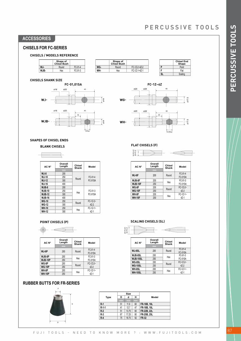
F U J I T O O L S - N E E D T O K N O W M O R E ? : W W W . F U J I T O O L S . C O M 87
Ø16
Ø14
Ø20 45
Ø14
12Hex
Ø16 Ø20 45
18
Ø20 Ø28
Ø17
.5
60
Ø20 Ø28
22
Ø17
.5
60
14.8Hex16
FC
-01
20 F
C-Z
25 F
C-0
132
FC
-Z
WJ-
WJB-
WG-
WH-
d
H
D
PER
CUSS
IVE
TOO
LS
CHISELS FOR FC-SERIES
RUBBER BUTTS FOR FR-SERIES
CHISELS / MODELS REFERENCE
CHISELS SHANK SIZE
SHAPES OF CHISEL ENDS
FC-01,01SA FC-1Z~4Z
Shape of Chisel Bush
WJ- Round FC-01-4WJB- Hex FC-01-3
Shape of Chisel Bush
WG- Round FC-1Z-2~4Z-2WH- Hex FC-1Z-1~4Z-1
Chisel End Shape
P PointF FlatSL Scaling
BLANK CHISELS FLAT CHISELS (F)
SCALING CHISELS (SL)POINT CHISELS (P)
AC N°Overall Length Chisel
Shank Modelmm
WJ-8 200
Round FC-01-4FC-01SA
WJ-10 250WJ-12 300WJ-16 400WJB-8 200
Hex FC-01-3FC-01SA
WJB-10 250WJB-12 300WJB-16 400WG-10 250 Round FC-1Z-2~
4Z-2WG-12 300WH-10 250 Hex FC-1Z-1~
4Z-1WH-12 300
AC N°Overall Length Chisel
Shank Modelmm
WJ-8P 200 Round FC-01-4FC-01SA
WJB-8P 200 Hex FC-01-3FC-01SAWJB-10P 250
WG-8P 200 Round FC-1Z-2~4Z-2WG-10P 250
WH-8P 200 Hex FC-1Z-1~4Z-1WH-10P 250
AC N°Overall Length Chisel
Shank Modelmm
WJ-8SL 200 Round FC-01-4FC-01SA
WJB-8SL 200 Hex FC-01-3FC-01SAWJB-10SL 250
WG-8SL 200 Round FC-1Z-2~4Z-2WG-10SL 250
WH-8SL 200 Hex FC-1Z-1~4Z-1WH-10SL 250
AC N°Overall Length Chisel
Shank Modelmm
WJ-8F 200 Round FC-01-4FC-01SA
WJB-8F 200 Hex FC-01-3FC-01SAWJB-10F 250
WG-8F 200 Round FC-1Z-2~4Z-2WG-10F 250
WH-8F 200 Hex FC-1Z-1~4Z-1WH-10F 250
TypeSize
ModelD d Hmm mm mm
R-1 51 11.8 60 FR-18B, 18LR-1-1 41 12.7 47 FR-18B, 18LR-2 51 13.75 60 FR-22B, 22LR-3 67 17.25 80 FR-25B, 25LR-4 75 18.75 92 FR-32
P E R C U S S I V E T O O L S
ACCESSORIES

F U J I T O O L S - N E E D T O K N O W M O R E ? : W W W . F U J I T O O L S . C O M88
PER
CUSS
IVE
TOO
LS N O T E S

F U J I T O O L S - N E E D T O K N O W M O R E ? : W W W . F U J I T O O L S . C O M 89
AIR MOTORS
REVERSIBLE / NON-REVERSIBLE TYPE ________________________ 90
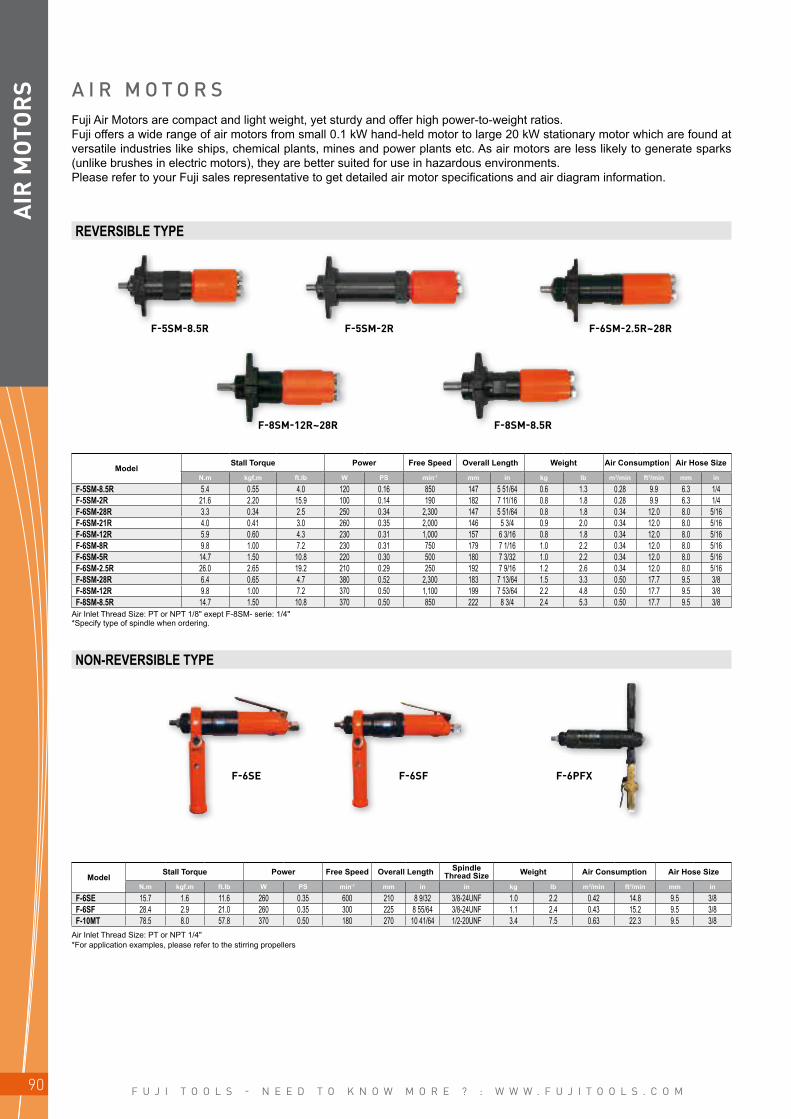
F U J I T O O L S - N E E D T O K N O W M O R E ? : W W W . F U J I T O O L S . C O M90
F-5SM-8.5R F-5SM-2R F-6SM-2.5R~28R
F-8SM-12R~28R F-8SM-8.5R
F-6SE F-6SF F-6PFX
AIR
MOT
OR
S
*Specify type of spindle when ordering.
*For application examples, please refer to the stirring propellers
A I R M O T O R SFuji Air Motors are compact and light weight, yet sturdy and offer high power-to-weight ratios.Fuji offers a wide range of air motors from small 0.1 kW hand-held motor to large 20 kW stationary motor which are found at versatile industries like ships, chemical plants, mines and power plants etc. As air motors are less likely to generate sparks (unlike brushes in electric motors), they are better suited for use in hazardous environments.Please refer to your Fuji sales representative to get detailed air motor specifications and air diagram information.
REVERSIBLE TYPE
NON-REVERSIBLE TYPE
ModelStall Torque Power Free Speed Overall Length Weight Air Consumption Air Hose Size
N.m kgf.m ft.lb W PS min-1 mm in kg lb m3/min ft3/min mm in
F-5SM-8.5R 5.4 0.55 4.0 120 0.16 850 147 5 51/64 0.6 1.3 0.28 9.9 6.3 1/4F-5SM-2R 21.6 2.20 15.9 100 0.14 190 182 7 11/16 0.8 1.8 0.28 9.9 6.3 1/4F-6SM-28R 3.3 0.34 2.5 250 0.34 2,300 147 5 51/64 0.8 1.8 0.34 12.0 8.0 5/16F-6SM-21R 4.0 0.41 3.0 260 0.35 2,000 146 5 3/4 0.9 2.0 0.34 12.0 8.0 5/16F-6SM-12R 5.9 0.60 4.3 230 0.31 1,000 157 6 3/16 0.8 1.8 0.34 12.0 8.0 5/16F-6SM-8R 9.8 1.00 7.2 230 0.31 750 179 7 1/16 1.0 2.2 0.34 12.0 8.0 5/16F-6SM-5R 14.7 1.50 10.8 220 0.30 500 180 7 3/32 1.0 2.2 0.34 12.0 8.0 5/16F-6SM-2.5R 26.0 2.65 19.2 210 0.29 250 192 7 9/16 1.2 2.6 0.34 12.0 8.0 5/16F-8SM-28R 6.4 0.65 4.7 380 0.52 2,300 183 7 13/64 1.5 3.3 0.50 17.7 9.5 3/8F-8SM-12R 9.8 1.00 7.2 370 0.50 1,100 199 7 53/64 2.2 4.8 0.50 17.7 9.5 3/8F-8SM-8.5R 14.7 1.50 10.8 370 0.50 850 222 8 3/4 2.4 5.3 0.50 17.7 9.5 3/8
ModelStall Torque Power Free Speed Overall Length Spindle
Thread Size Weight Air Consumption Air Hose Size
N.m kgf.m ft.lb W PS min-1 mm in in kg lb m3/min ft3/min mm in
F-6SE 15.7 1.6 11.6 260 0.35 600 210 8 9/32 3/8-24UNF 1.0 2.2 0.42 14.8 9.5 3/8F-6SF 28.4 2.9 21.0 260 0.35 300 225 8 55/64 3/8-24UNF 1.1 2.4 0.43 15.2 9.5 3/8F-10MT 78.5 8.0 57.8 370 0.50 180 270 10 41/64 1/2-20UNF 3.4 7.5 0.63 22.3 9.5 3/8
Air Inlet Thread Size: PT or NPT 1/8" exept F-8SM- serie: 1/4"
Air Inlet Thread Size: PT or NPT 1/4"
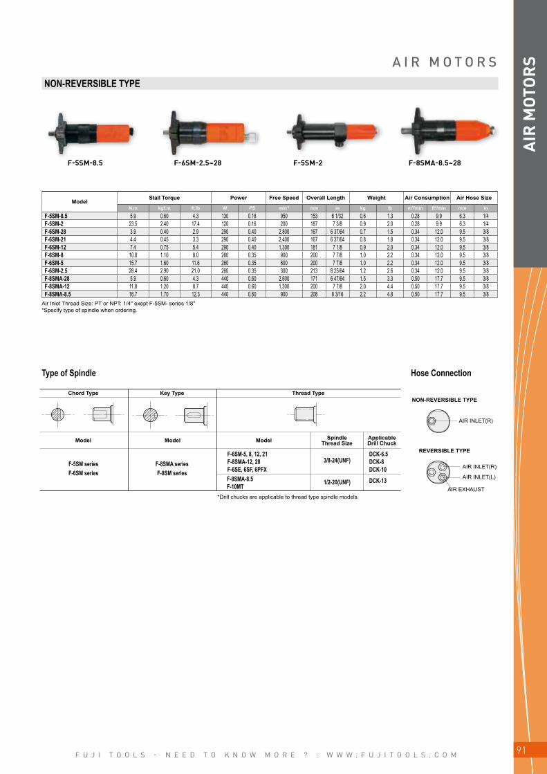
F U J I T O O L S - N E E D T O K N O W M O R E ? : W W W . F U J I T O O L S . C O M 91
AIR
MOT
OR
SA I R M O T O R SNON-REVERSIBLE TYPE
F-5SM-8.5 F-6SM-2.5~28 F-5SM-2 F-8SMA-8.5~28
ModelStall Torque Power Free Speed Overall Length Weight Air Consumption Air Hose Size
N.m kgf.m ft.lb W PS min-1 mm in kg lb m3/min ft3/min mm in
F-5SM-8.5 5.9 0.60 4.3 130 0.18 950 153 6 1/32 0.6 1.3 0.28 9.9 6.3 1/4F-5SM-2 23.5 2.40 17.4 120 0.16 200 187 7 3/8 0.9 2.0 0.28 9.9 6.3 1/4F-6SM-28 3.9 0.40 2.9 290 0.40 2,800 167 6 37/64 0.7 1.5 0.34 12.0 9.5 3/8F-6SM-21 4.4 0.45 3.3 290 0.40 2,400 167 6 37/64 0.8 1.8 0.34 12.0 9.5 3/8F-6SM-12 7.4 0.75 5.4 290 0.40 1,300 181 7 1/8 0.9 2.0 0.34 12.0 9.5 3/8F-6SM-8 10.8 1.10 8.0 260 0.35 900 200 7 7/8 1.0 2.2 0.34 12.0 9.5 3/8F-6SM-5 15.7 1.60 11.6 260 0.35 600 200 7 7/8 1.0 2.2 0.34 12.0 9.5 3/8F-6SM-2.5 28.4 2.90 21.0 260 0.35 300 213 8 25/64 1.2 2.6 0.34 12.0 9.5 3/8F-8SMA-28 5.9 0.60 4.3 440 0.60 2,600 171 6 47/64 1.5 3.3 0.50 17.7 9.5 3/8F-8SMA-12 11.8 1.20 8.7 440 0.60 1,300 200 7 7/8 2.0 4.4 0.50 17.7 9.5 3/8F-8SMA-8.5 16.7 1.70 12.3 440 0.60 900 208 8 3/16 2.2 4.8 0.50 17.7 9.5 3/8
*Specify type of spindle when ordering.
*Drill chucks are applicable to thread type spindle models.
Type of Spindle Hose Connection
Chord TypeNON-REVERSIBLE TYPE
REVERSIBLE TYPE
Model Model Model Spindle Thread Size
Applicable Drill Chuck
Key Type Thread Type
F-5SM seriesF-6SM series
F-8SMA seriesF-8SM series
DCK-6.5DCK-8DCK-10
3/8-24(UNF)
1/2-20(UNF) DCK-13
F-6SM-5, 8, 12, 21 F-8SMA-12, 28 F-6SE, 6SF, 6PFXF-8SMA-8.5F-10MT
AIR INLET(R)
AIR INLET(L)
AIR EXHAUST
Air Inlet Thread Size: PT or NPT: 1/4" exept F-5SM- series 1/8"
AIR INLET(R)

F U J I T O O L S - N E E D T O K N O W M O R E ? : W W W . F U J I T O O L S . C O M92
AIR
MOT
OR
S N O T E S

F U J I T O O L S - N E E D T O K N O W M O R E ? : W W W . F U J I T O O L S . C O M 93
COMPLEMENTARY RANGE
AIR FILES / AIR SAWS _______________________________________________________ 94
CHAMFERING / ALUMINUM MILLING MACHINES ________ 95
PIPE BEVELLING MACHINES __________________________________________ 96
SUMP PUMPS / PISTON PUMPS _____________________________________ 98
TIP DRESSERS ___________________________________________________________________ 99
MARKING PEN / AIR CLEANERS _____________________________________ 100

F U J I T O O L S - N E E D T O K N O W M O R E ? : W W W . F U J I T O O L S . C O M94
FRF-4-1, 2FRS-45
1
2
3
4
5
12
W
L
18
22L
W
COM
PLEM
ENTA
RY
RA
NG
E
*Models marked 1F, 2F are locking lever handle types.
• =Accessories included in FRF-4-1, 1F
A I R F I L E S / A I R S A W SFuji FRF series compact Air File & Saws feature reduced vibration and are designed for deburring, filing and cutting of metal, wood, plastic, and fibreglass.The FRS-45 Air Saw is equipped with a damper to minimize vibration and, a stroke regulator and blade cooling device. The cutting direction is adjustable to provide optimal operator comfort.
Model Tool Name
Stroke Per Minute SPM
Stroke Chuck Capacity Overall Length Weight Max. Air Consumption Air Hose Sizemm in mm in mm in kg lb m3/min ft3/min mm in
FRF-4-1F File 1,600 12.0 15/32 4.0 x 13.0 x 20 5/32 x 1/2 x 25/32 229 9 1/32 0.8 1.7 0.28 9.9 6.3 1/4FRF-4-2F Saw 1,600 12.0 15/32 2.0 x 13.0 x 20 5/64 x 1/2 x 25/32 233 9 3/16 0.8 1.7 0.28 9.9 6.3 1/4FRS-45 Saw 1,200 45.0 1 25/32 2.5 x 17.7 x 31 3/32 x 45/64 x 1 7/32 419 16 1/2 2.9 6.3 0.40 14.1 9.5 3/8
Model Tool Name
Stroke Per Minute SPM
Strokemm
1 •FILE-4P Pillar
1502 •FILE-4H Half Round3 •FILE-4R Round4 •FILE-4C Triangle5 •FILE-4S Square Model
StrokeL
mmmm
•SAW-4 123 25
FILE BLADES FOR FRF-4-1, 1F
SAW BLADES FOR FRS-45
STANDARD ACCESSORIES FOR FRS-45
SAW BLADE FOR FRF-4-2, 2F
• =Accessories included in FRF-4-2, 2F.* W =The number of teeth per inch.
• =Accessories included in FRS-45. W =The number of teeth per inch.*Using cutting fluid extends life of blade. A mixture of turpentine and kerosene with spindle oil, *soapsuds, grease at the rate of 7 to 3 is recommended.
AC N°Size
Cutting MaterialsL WmmSAW-2014 200 14 steel plate, pipe, copper, brass, plastic, slate•SAW-2018 200 18 steel plate, pipe•SAW-2024 200 24 steel plate, pipe•SAW-2514 250 14 steel plate, pipe, copper, brass, plastic, slate•SAW-2518 250 18 steel plate, pipe•SAW-3014 300 14 steel plate, pipe, copper, brass, plastic, slate•SAW-3018 300 18 steel plate, pipe
SAW-2018SAW-2024F-704F-706AO-30CASE-T431
Saw Blade (1)Saw Blade (1)4mm Hex. Pin Wrench (1)6mm Hex. Pin Wrench (1)Oil (1)Steel Case (1)
Air Inlet Thread Size: PT or NPT1/4"
ACCESSORIES
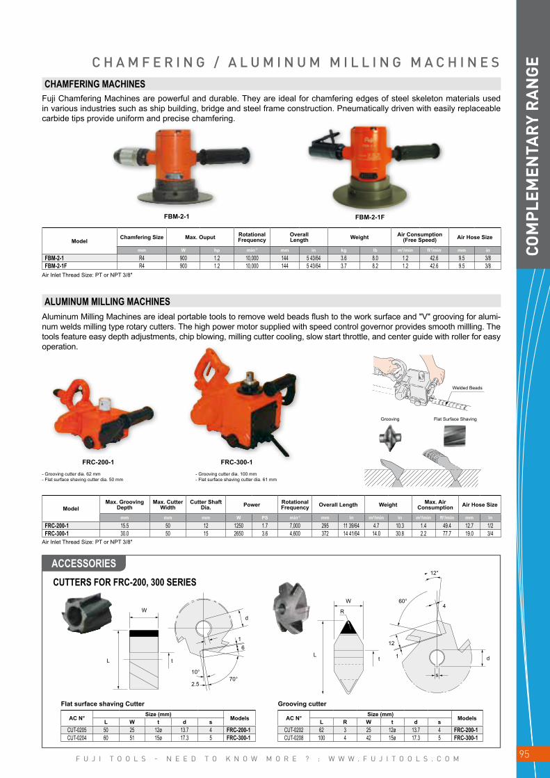
F U J I T O O L S - N E E D T O K N O W M O R E ? : W W W . F U J I T O O L S . C O M 95
FBM-2-1 FBM-2-1F
W
L t
d
16
70°10°
2.5
R
W
Lt
12°
60°4
12
1
s
d
FRC-200-1 FRC-300-1
COM
PLEM
ENTA
RY
RA
NG
EC H A M F E R I N G / A L U M I N U M M I L L I N G M A C H I N E S
CUTTERS FOR FRC-200, 300 SERIES
ALUMINUM MILLING MACHINES
CHAMFERING MACHINES
AC N°Size (mm)
ModelsL W t d sCUT-0205 50 25 12ø 13.7 4 FRC-200-1CUT-0204 60 51 15ø 17.3 5 FRC-300-1
AC N°Size (mm)
ModelsL R W t d sCUT-0202 62 3 25 12ø 13.7 4 FRC-200-1CUT-0208 100 4 42 15ø 17.3 5 FRC-300-1
ModelMax. Grooving
DepthMax. Cutter
WidthCutter Shaft
Dia. Power Rotational Frequency Overall Length Weight Max. Air
Consumption Air Hose Size
mm mm mm W PS min-1 mm in m3/min in m3/min ft3/min mm in
FRC-200-1 15.5 50 12 1250 1.7 7,000 295 11 39/64 4.7 10.3 1.4 49.4 12.7 1/2FRC-300-1 30.0 50 15 2650 3.6 4,600 372 14 41/64 14.0 30.8 2.2 77.7 19.0 3/4
ModelChamfering Size Max. Ouput Rotational
FrequencyOverall Length Weight Air Consumption
(Free Speed) Air Hose Size
mm W hp min-1 mm in kg lb m3/min ft3/min mm in
FBM-2-1 R4 900 1.2 10,000 144 5 43/64 3.6 8.0 1.2 42.6 9.5 3/8FBM-2-1F R4 900 1.2 10,000 144 5 43/64 3.7 8.2 1.2 42.6 9.5 3/8
Grooving Flat Surface Shaving
- Grooving cutter dia. 62 mm- Flat surface shaving cutter dia. 50 mm
- Grooving cutter dia. 100 mm- Flat surface shaving cutter dia. 61 mm
Flat surface shaving Cutter Grooving cutter
Aluminum Milling Machines are ideal portable tools to remove weld beads flush to the work surface and "V" grooving for alumi-num welds milling type rotary cutters. The high power motor supplied with speed control governor provides smooth millling. The tools feature easy depth adjustments, chip blowing, milling cutter cooling, slow start throttle, and center guide with roller for easy operation.
Fuji Chamfering Machines are powerful and durable. They are ideal for chamfering edges of steel skeleton materials used in various industries such as ship building, bridge and steel frame construction. Pneumatically driven with easily replaceable carbide tips provide uniform and precise chamfering.
Welded Beads
Air Inlet Thread Size: PT or NPT 3/8"
Air Inlet Thread Size: PT or NPT 3/8"
ACCESSORIES
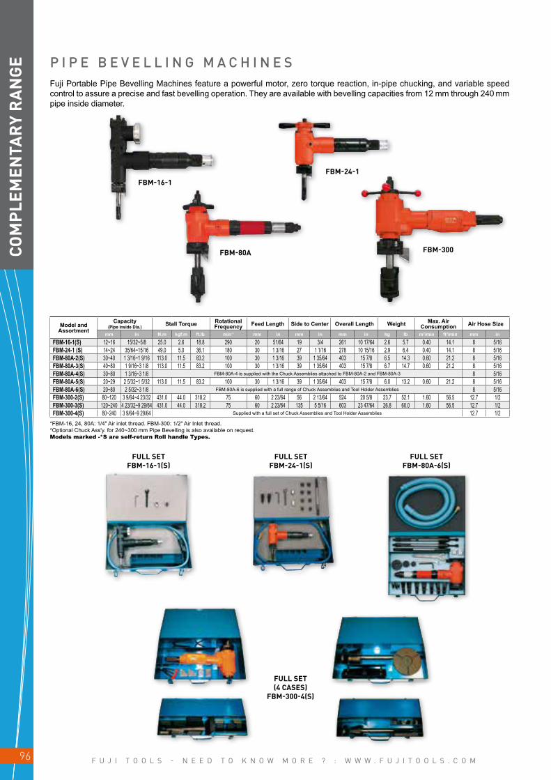
F U J I T O O L S - N E E D T O K N O W M O R E ? : W W W . F U J I T O O L S . C O M96
FBM-16-1
FBM-80A FBM-300
FBM-24-1
COM
PLEM
ENTA
RY
RA
NG
E P I P E B E V E L L I N G M A C H I N E S
FULL SET FBM-16-1(S)
FULL SET FBM-24-1(S)
FULL SET (4 CASES)
FBM-300-4(S)
FULL SET FBM-80A-6(S)
Model and Assortment
Capacity (Pipe inside Dia.) Stall Torque Rotational
Frequency Feed Length Side to Center Overall Length Weight Max. Air Consumption Air Hose Size
mm in N.m kgf.m ft.lb min-1 mm in mm in mm in kg lb m3/min ft3/min mm in
FBM-16-1(S) 12~16 15/32~5/8 25.0 2.6 18.8 290 20 51/64 19 3/4 261 10 17/64 2.6 5.7 0.40 14.1 8 5/16FBM-24-1 (S) 14~24 35/64~15/16 49.0 5.0 36.1 180 30 1 3/16 27 1 1/16 278 10 15/16 2.9 6.4 0.40 14.1 8 5/16FBM-80A-2(S) 30~40 1 3/16~1 9/16 113.0 11.5 83.2 100 30 1 3/16 39 1 35/64 403 15 7/8 6.5 14.3 0.60 21.2 8 5/16FBM-80A-3(S) 40~80 1 9/16~3 1/8 113.0 11.5 83.2 100 30 1 3/16 39 1 35/64 403 15 7/8 6.7 14.7 0.60 21.2 8 5/16FBM-80A-4(S) 30~80 1 3/16~3 1/8 FBM-80A-4 is supplied with the Chuck Assemblies attached to FBM-80A-2 and FBM-80A-3 8 5/16FBM-80A-5(S) 20~29 2 5/32~1 5/32 113.0 11.5 83.2 100 30 1 3/16 39 1 35/64 403 15 7/8 6.0 13.2 0.60 21.2 8 5/16FBM-80A-6(S) 20~80 2 5/32~3 1/8 FBM-80A-6 is supplied with a full range of Chuck Assemblies and Tool Holder Assemblies 8 5/16FBM-300-2(S) 80~120 3 9/64~4 23/32 431.0 44.0 318.2 75 60 2 23/64 56 2 13/64 524 20 5/8 23.7 52.1 1.60 56.5 12.7 1/2FBM-300-3(S) 120~240 4 23/32~9 29/64 431.0 44.0 318.2 75 60 2 23/64 135 5 5/16 603 23 47/64 26.8 60.0 1.60 56.5 12.7 1/2FBM-300-4(S) 80~240 3 9/64~9 29/64 Supplied with a full set of Chuck Assemblies and Tool Holder Assemblies 12.7 1/2
Fuji Portable Pipe Bevelling Machines feature a powerful motor, zero torque reaction, in-pipe chucking, and variable speed control to assure a precise and fast bevelling operation. They are available with bevelling capacities from 12 mm through 240 mm pipe inside diameter.
*FBM-16, 24, 80A: 1/4" Air inlet thread. FBM-300: 1/2" Air Inlet thread.*Optional Chuck Ass'y. for 240~300 mm Pipe Bevelling is also available on request.Models marked -*S are self-return Roll handle Types.

F U J I T O O L S - N E E D T O K N O W M O R E ? : W W W . F U J I T O O L S . C O M 97
•
∆
COM
PLEM
ENTA
RY
RA
NG
E
ACCESSORIES
C O M P L E M E N T A R Y R A N G E
FBM-16, 24, 80A, 300
FBM-16-1FBM-24-1FBM-80A (20mm~29mm)
FBM-80A (30mm~80mm)FBM-300 (240mm) 3 pcs are necesary for each size
Parts N°Pipe size
mm
S-138638-00 12~16S-138638-01 14~16S-138638-03 18~20
Parts N°Pipe size
mm
S-120638-10 14~16S-120638-11 16~18S-120638-12 18~20S-120638-13 20~22S-120638-14 22~24
ModelsParts N° (S-121638) Parts N° (S-162638)-00
20~23-01
23~26-02
26~29-00
30~35-01
35~40-02
40~48-03
48~56-04
56~64-05
64~72-06
72~80
-2(30~40mm) – – – • • – – – – –-3(40~80mm) – – – – – • • • • •-4(30~80mm) – – – • • • • • • •-5(20~29mm) ∆ ∆ ∆ – – – – – – –-6(20~80mm) ∆ ∆ ∆ • • • • • • •
ModelsParts N° (S-158638)
-00 80~90
-01 90~100
-02 100~110
-03 110~120
-04 120~130
-05 130~140
-06 140~150
-07 150~160
-08 160~170
-09 170~180
-10 180~190
-11 190~200
-12 200~210
-13 210~220
-14 220~230
-15 230~240
-2(80~120mm) • • • • – – – – – – – – – – – –-3(120~240mm) – – – – • • • • • • • • • • • •
FBM-16-1, 1S ∆
CHUCK TYPE ∆ CHUCK TYPE •
FOR FBM-80A ∆ •
FOR FBM-300 •
FBM-24-1, 1S ∆
Bit Tool Shape Parts N°Parts N° Dimensions (mm)
Models(Q) a b Thickness
For Exterior BevellingBIT-016E01 30˚ 12 25 6.0 FBM-16BIT-024E01 30˚ 14 30 8.0 FBM-24BIT-042E02 37.5˚ 35 56 11.5
FBM-80A, 300BIT-042E03 45˚ 25 50 11.5BIT-042E06 30˚ 25 40 11.5BIT-042E01 30˚ 35 50 11.5 FBM-300BIT-120E01 30˚ 60 60 11.5 FBM-80A, 300
For Interior BevellingBIT-024B06 30˚ 14 30 8.0 FBM-24BIT-042B01 30˚ 25 40 11.5
FBM-80A, 300BIT-042B02 45˚ 25 50 11.5
For Surface BevellingBIT-024F01 – 14 25 8.0 FBM-24BIT-042F02 – 25 30 11.5 FBM-80A, 300BIT-120F01 – 60 40 11.5 FBM-300
a
a
a
b
b
b
Q
Q
CHUCKS PROVIDED FOR FBM-16, 24, 80A AND 300
STANDARD BIT TOOLS
*Bit Tools provided: FBM-16: Bit-016E01. FBM-24: BIT-024E01, 024F01 FBM-80A: BIT-042E06, 042F02 FBM-300: BIT-120E01, 120F01*Other sizes of Bit Tool are available. Specify dimensions when ordering.
Pipe Chuck Pipe Chuck

F U J I T O O L S - N E E D T O K N O W M O R E ? : W W W . F U J I T O O L S . C O M98
= = = =
30
30
40
40
50
(m)
(m)
(m)
20
20
30
10
10
20
10
1
10
10 20 30 40 50 60 70 80
20 30 40 50
2 3 4 5 6 7 8
0.7MPa
0.7MPa
0.63MPa0.5MPa0.4MPa
0.63MPa
0.63MPa
0.5MPa
0.5MPa
0.4MPa
0.4MPa
0.63MPa0.5MPa0.4MPa0.3MPa
1
10
20
30
40
50
(m)
2 3 4
COM
PLEM
ENTA
RY
RA
NG
E S U M P P U M P S / P I S T O N P U M P S
FP-7-2
FP-11-1 FP-11-2
FP-7-2
FP-20-1
FP-35-1
FP-20-1 FP-35-1
ModelDischarge Volume Piston Diameter Stroke Stroke
N° Overall Length Weight Max. Air Consumption Air Hose Size
m3/hr mm in mm in Hz mm in kg lb m3/min ft3/min mm in
FP-11-1 4.2 48 1 57/64 100 3 15/16 4 622 24 31/64 4.7 10.3 0.20 7.1 9.5 3/8FP-11-2 4.2 48 1 57/64 100 3 15/16 4 622 24 31/64 7.8 17.2 0.20 7.1 9.5 3/8
Fuji Sump Pumps are indespensable for discharging water, oil, sewage and sludge from sumps, trenches, manholes, bilges and tanks. They may be used in non-spark environments and their housing are rust-proof.
PUMPING PERFORMANCE CURVE
PUMPING PERFORMANCE CURVE
SUMP PUMPS
PISTON PUMPS
ModelCapacity Water
Output Thread Size
Air Outlet Thread Size Height Weight Max. Air
Consumption Air Hose SizeHead Discharge
m ft m3/h l/min PT mm in kg lb m3/min ft3/min mm in
FP-7-2 15 49 4.2 70 PT3/4 3/4 234 9 1/4 4.3 9.4 0.80 28.2 9.5 3/8FP-20-1 20 66 28.0 467 W82.5-5 1 374 14 3/4 22.0 48.4 3.40 120.1 19.0 3/4FP-35-1 28 92 28.0 467 W82.5-5 1 1/4 410 16 9/64 34.0 74.8 5.20 183.6 25.4 1
Fuji Piston Pumps FP-11 series are ideal pumps for pumping oil out from tanks and bilges in the vessels. Various flanges are optionally available for hose connection.
*Testing Oil ... ISO VG32Oil
Discharge (m3/h)
Discharge (m3/h)
Discharge (m3/h)
Pum
ping
Hea
dP
umpi
ng H
ead
Pum
ping
Hea
d
FP-11-1, 2
Discharge (m3/h)
Pum
ping
Hea
d
Air Inlet Thread Size: PT or NPT 3/8". FP35-1 : 1".
Air Inlet Thread Size: PT or NPT 1/4".

F U J I T O O L S - N E E D T O K N O W M O R E ? : W W W . F U J I T O O L S . C O M 99
(1)
R x ØD
D
R R RR
A A A
r
D D D D
R x ØD ØA x R x ØA r x ØA x R x ØD r x °x ØD
(2) (3) (4) (5)
(6) (7) (8) (9)
ØA x °x ØD r x ØA x °x ØD ØA x r x °x ØD F x ØD
D D D D
A A A
ØD
Ø22.2
FTD-18-1 FTD-18A-1
r
COM
PLEM
ENTA
RY
RA
NG
ET I P D R E S S E R SFuji Tip Dresser FTD-18 series are designed to be compact, light weight and ideal for dressing tips in narrow space between opposing tips on electric spot welders. Patent applied FTD-18A clamp system provides excellent tip center alignment and accurate tip repairing. Various types of welding tips can be dressed by replacing cutter and cutter case.
ModelCapacity Tip Size Max. Clamp
Height Free Speed Overall Length Weight Max. Air Consumption Air Hose Size
mm in mm in min-1 mm in kg lb m3/min ft3/min mm in
FTD-18-1 12~16 15/32~5/8 – – 1,300 290 11 7/16 1.65 3.64 0.5 17.7 9.5 3/8FTD-18A-1 13~16 33/64~5/8 25 63/64 1,300 307 12 3/32 2.02 4.45 0.5 17.7 9.5 3/8
CLASSIFICATION TABLE FOR CUTTERS SHAPES OF TIPS AND CUTTERS
Type Item N° Tip shape (Normal)
Max. diameter repaired (ØD) Standard
(1) CUT-1001 6R ø12 6R x ø12CUT-1002 6.5R ø13 6.5R x ø13CUT-1003 8R ø16 8R x ø16
(2) CUT-2001 16R x ø16– 10R~150R ø16 –
(3) – øA x 6R ø12 –– øA x 6.5R ø13 –
CUT-3001 ø5 x 8R x ø16CUT-3002 øA x 8R ø16 ø6 x 8R x ø16
(4) – r x øA x 6R ø12 –CUT-1002 r x øA x 6.5R ø13 –CUT-1003 r x øA x 8R ø16 40r x ø6 x 8R x ø16
(5) – 5~6r x 60˚ ø13 –– 3r or more x 90˚ ø16 –
(6) – 7~ø9 x 50˚ ø13 –– ø10 or more x 50˚ ø16 –
CUT-6001 5~ø7 x 60˚ ø13 ø6 x 60˚ x ø13– ø8 or more x 60˚ ø16 –– 3~ø4 x 75˚ ø13 –
CUT-6002 ø5 or more x 75˚ ø16 ø6 x 75˚ x ø16CUT-6003 ø3 or more x 90˚ ø16 ø4 x 90˚ x ø16CUT-6004 ø3 or more x 90˚ ø16 ø6 x 90˚ x ø16
– ø3 or more x 120˚ ø16 –(7) – r x øA x˚ øD –(8) – øA x r x˚ øD –(9) – F ø16 –
* Beside item listed above table, minimum 10pcs. per item is required for ordering optional cutters. Specify the nominal dimensions when ordering.
*Cutter is not provided as a standard accessory.
CUTTER CASES
<FTD-18A-1> PAT.P
*Cutter dresses Welding Tip correctly as inside diameter (dia. D) of cutter case act as a guide. Specify cutter case diameter which matches tip size. dia. 16 cutter case is included as a standard accessory. Specify cutter case dia. 12 or dia. 13 otherwise.
Item N° ØD
S-167716-00 16S-167716-01 13S-167716-02 12 TIP
Holder
Air Inlet Thread Size: PT or NPT 1/4".
ACCESSORIES

F U J I T O O L S - N E E D T O K N O W M O R E ? : W W W . F U J I T O O L S . C O M100
AC-200F FJP-500
1
2
3
5
4
7
6
COM
PLEM
ENTA
RY
RA
NG
E M A R K I N G P E N / A I R C L E A N E R S
Fuji Marking Pen features a lower vibration level when compared to conventional marking pens enabling operators to use this tool for a full working day. This tool also requires no lubrication and meets requirements where oil free operation is specified.
Fuji air cleaners remove dust, chips, sawdust, water and oil with their powerful vacuum action.
ModelDiameter Overall Length Weight Air Consumption
(at Load)mm in mm in kg lb m3/min ft3/min
G-400 20 25/32 140 5 1/2 0.15 0.33 0.03 1.1
ModelVaccum Degree Overall Length Outside Dia. of
Discharge Weight Max. Air Consumption Air Hose Size
mm Hg in Hg mm in mm kg lb m3/min ft3/min mm in
AC-200F 130 5 1/8 145 5 45/64 34 0.5 1.1 0.60 21.2 9.5 3/8FJP-500 200 7 7/8 1020 40 5/32 37.5 1.5 3.3 1.10 38.8 9.5 3/8
AIR CLEANERS
MARKING PEN
G-400
ACCESSORIES PROVIDED FOR AC-200F
Index N° AC N° Name1 ACB-1F Main Nozzle2 ACB-2F Fan Shape Nozzle3 ACB-3F Small-Size End Nozzle4 ACB-4F Flexible Hose5 ACB-5F Rubber Joint6 ACB-6F Dust Bag7 ACB-7F Hose Band
Air Inlet Thread Size: PT or NPT : 1/4 for AC-200F - FJP-500 : 3/8.
ACCESSORIES

F U J I T O O L S - N E E D T O K N O W M O R E ? : W W W . F U J I T O O L S . C O M 101
SERVICE TOOLING
SPANNERS AND WRENCHES FOR MAINTENANCE _________________________________________________________ 102
AIR COMPRESSOR / AIR PRESSURE ______________________________ 103

F U J I T O O L S - N E E D T O K N O W M O R E ? : W W W . F U J I T O O L S . C O M102
L
S
t
L
105
59
Ø9
2
�
L
S
t
L
H
BHex
3.5
L
L
t
t
BHex
BHex
SER
VICE
TO
OLI
NG
OPEN-END WRENCHES
HOOK SPANNERS
OPEN-END PIN WRENCHES HEXAGONAL PIN WRENCHES
HEXAGONAL WRENCHES
ANGLE WRENCH
AC N°Size
ModelsS L tmm mm mm
F-100 5.5 81 2.5 FBM-1-1, 1F, 2, 2FF-101 8.0 80 3.0 FG-13, 13X, TURBO-100F-102 9.5 80 1.5 FCD-6A, 6BF-103 10.0 80 3.0 FRD-5P-1, 5S-1, 1F, 6PX-2, 3, 5, •F-6SM-12, 21, 28, 28R, FRD-6S-2, 3, 5
F-103-1 10.0 105 4.0 FBM-16, 24F-104 12.0 88 3.0 FG-12U, 12UX, 25D, 25DX, 50D, 50DX, FRD-8PX-1, 2, •F-5SM-2, 8.5, •8SMA-12, 28
F-105 14.0 100 3.0FG-12U, 12UX, 2VX-1F, 3VX-1F, 6F, 25D, 25DX, 50DX, 26, 26X, 50X, 50D, FA-2C,2CX, TURBO-100A, FRD-6PX-7, 6S-7, 7F, 8PX-3, •F-6SM-2.5, 2.5R, •5, 8, F-6SE, 6SF, •8SM-8.5RA, •8SMA-8.5, 6PFX
F-106 17.0 130 3.0 FRD-16Z, FCD-6X, F-10MTF-117-1 17.0 150 6.0 FBM-300F-107 19.0 130 3.0 FCD-10X, FA-2C, 2CX, FT-8PX, FBM-80AF-117 21.0 180 5.0 FG-3H, 3HL, 4HL, 50L, 50YF-109 24.0 200 4.0 FA-5E-3 Series, 7E-5, 6, 8 Series, FV-7, 9BH-1M, FX-027-1, FA-6C-6M, 8M, 9M, 9C-4, 4M
F-110 26.0 170 4.5 FA-150KG-5, 7, FA-5E-1, 2, 8, 13 Series,FA-7E-1, 2, 3 Series, 6C-1, 10, 12, 12M, 20, 9C-2, 2M, 7C-21
F-111 27.0 170 4.5 FG-5PX, FD-4, 4PF-112 32.0 170 4.5 FG-3VX-2F, 3F, 4H, 4VA, 5HL, FA-4C, 4CH, 4CHK-1, FD-5, 5PF-113 41.0 180 4.0 FV-9BH-4M, FRC-300-1
AC N°Size
ModelsS Lmm mm
F-401 130 2 FD-4P, 4F-402 160 2 FD-5P, 5F-404 135 4.5 FA-3C, 3CXF-405 170 4.5 FA-4CHK-3, 150K-2, 3
AC N° Models
F-601 FD-5, 5P
* • =Thread Spindle type
AC N°Size
ModelsS L tmm mm mm
F-201 16 130 4.0 FG-5PXF-202 30 160 4.5 FV-9BH-4M
F-203 32 180 4.5 FA-6C, 9C, 5E-13 Series, 7E-5, 6, 8 Series,FV-7-1M, 2M, 4M, 9BH-1M
AC N°Size
B(Hex) L Hmm in mm mm
F-701-2 1.27 - 45 10F-701 1.5 - 52 12
F-701-1 1.5 - 52 52F-712 2.0 - 58 12
F-702-1 2.0 - 60 60F-702 2.5 - 60 15F-703 3.0 - 65 20F-704 4.0 - 72 25F-705 5.0 - 80 28F-706 6.0 - 90 32F-707 - 1/4 90 32F-708 8.0 - 100 36F-710 - 3/8 112 40F-709 10.0 - 112 40
AC N°Size
ModelsB(Hex) L tmm mm mm
F-301 8 80 3 TURBO-100, FG-06-1, 13, 13XF-304 9 100 3 FG-06-1F-306 14 101 4 TURBO-100AF-302 17 135 2 FD-4P, 4F-303 21 138 2 FD-5P, 5
S P A N N E R S A N D W R E N C H E S F O R M A I N T E N A N C E
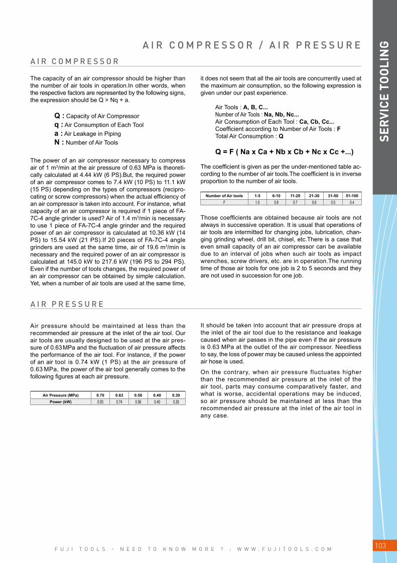
F U J I T O O L S - N E E D T O K N O W M O R E ? : W W W . F U J I T O O L S . C O M 103
SER
VICE
TO
OLI
NGA I R C O M P R E S S O R / A I R P R E S S U R E
The capacity of an air compressor should be higher than the number of air tools in operation.In other words, when the respective factors are represented by the following signs, the expression should be Q > Nq + a.
Q : Capacity of Air Compressor q : Air Consumption of Each Tool a : Air Leakage in Piping N : Number of Air Tools
The power of an air compressor necessary to compress air of 1 m3/min at the air pressure of 0.63 MPa is theoreti-cally calculated at 4.44 kW (6 PS).But, the required power of an air compressor comes to 7.4 kW (10 PS) to 11.1 kW (15 PS) depending on the types of compressors (recipro-cating or screw compressors) when the actual efficiency of an air compressor is taken into account. For instance, what capacity of an air compressor is required if 1 piece of FA-7C-4 angle grinder is used? Air of 1.4 m3/min is necessary to use 1 piece of FA-7C-4 angle grinder and the required power of an air compressor is calculated at 10.36 kW (14 PS) to 15.54 kW (21 PS).If 20 pieces of FA-7C-4 angle grinders are used at the same time, air of 19.6 m3/min is necessary and the required power of an air compressor is calculated at 145.0 kW to 217.6 kW (196 PS to 294 PS).Even if the number of tools changes, the required power of an air compressor can be obtained by simple calculation.Yet, when a number of air tools are used at the same time,
it does not seem that all the air tools are concurrently used at the maximum air consumption, so the following expression is given under our past experience.
Air Tools : A, B, C... Number of Air Tools : Na, Nb, Nc... Air Consumption of Each Tool : Ca, Cb, Cc... Coefficient according to Number of Air Tools : F Total Air Consumption : Q
Q = F ( Na x Ca + Nb x Cb + Nc x Cc +...)
The coefficient is given as per the under-mentioned table ac-cording to the number of air tools.The coefficient is in inverse proportion to the number of air tools.
Number of Air tools 1-5 6-10 11-20 21-30 31-50 51-100F 1.0 0.8 0.7 0.6 0.5 0.4
Those coefficients are obtained because air tools are not always in successive operation. It is usual that operations of air tools are intermitted for changing jobs, lubrication, chan-ging grinding wheel, drill bit, chisel, etc.There is a case that even small capacity of an air compressor can be available due to an interval of jobs when such air tools as impact wrenches, screw drivers, etc. are in operation.The running time of those air tools for one job is 2 to 5 seconds and they are not used in succession for one job.
A I R P R E S S U R E
A I R C O M P R E S S O R
Air pressure should be maintained at less than the recommended air pressure at the inlet of the air tool. Our air tools are usually designed to be used at the air pres-sure of 0.63 MPa and the fluctuation of air pressure affects the performance of the air tool. For instance, if the power of an air tool is 0.74 kW (1 PS) at the air pressure of 0.63 MPa, the power of the air tool generally comes to the following figures at each air pressure.
Air Pressure (MPa) 0.70 0.63 0.50 0.40 0.30Power (kW) 0.93 0.74 0.56 0.40 0.26
It should be taken into account that air pressure drops at the inlet of the air tool due to the resistance and leakage caused when air passes in the pipe even if the air pressure is 0.63 MPa at the outlet of the air compressor. Needless to say, the loss of power may be caused unless the appointed air hose is used.
On the contrary, when air pressure fluctuates higher than the recommended air pressure at the inlet of the air tool, parts may consume comparatively faster, and what is worse, accidental operations may be induced, so air pressure should be maintained at less than the recommended air pressure at the inlet of the air tool in any case.

F U J I T O O L S - N E E D T O K N O W M O R E ? : W W W . F U J I T O O L S . C O M104
a
a a
bb
j
k
h i
c d
j
k
c d
aa
b c db
k
c vb
j
k
c d
e
o h i
e f
w
ihe
k
o
h i
e
oh i
e
o
DIM
ENSI
ON
S
PULSE WRENCHNon Shut-off type (square)
Fig N° Model a b c d e h i j k o01 FL-4-1 139.5 23.5 35.5 80.5 44 144 169 11 12 3901 FL-5-1 139.5 23.5 35.5 80.5 44 144 169 11 12 3901 FL-6-1 151.5 23.5 40.5 87.5 44 144 169 11 12 3901 FL-7-1 157.0 24.5 53.0 79.5 51 147 173 12 12 3901 FL-9-1 175.0 29.0 59.5 86.5 51 150 179 17 16 4001 FL-11-1 184.5 29.0 64.5 91.0 65 160 191 17 16 4401 FL-13-1 193.5 29.0 67.5 97.0 69 162 196 17 16 44
PULSE WRENCHNon Shut-off type (square)
Fig N° Model a b c d e h i j k o02 FL-4D-1(10) 140 24 35.5 80.5 44 144 169 20 18 3902 FL-5D-1(10) 140 24 35.5 80.5 44 144 169 20 18 3902 FL-6D-1(10) 152 24 40.5 87.5 44 144 169 20 18 39
PULSE WRENCHShut-off type (square)
Fig N° Model a b c d e f h i j k01 FLT-4-1 180.5 23.5 54 103 44 142 169 11 12 4001 FLT-5-1 180.5 23.5 54 103 44 142 169 11 12 4001 FLT-6-1 192.5 23.5 59 110 44 142 169 11 12 4001 FLT-7-1 191.5 23.5 54 114 50 147 177 13 12 4001 FLT-9-1 210.5 28.0 61 122 56 150 181 18 16 4001 FLT-11-1 219.5 28.0 65 127 65 160 192 17 16 4301 FLT-13-1 229.5 28.0 67 135 68 163 200 17 16 45
PULSE WRENCHShut-off type (bit shank)
Fig N° Model a b c d e f h i j k02 FLT-4D-1(10) 181 24 54 103 44 142 169 20 18 4002 FLT-5D-1(10) 181 24 54 103 44 142 169 20 18 4002 FLT-6D-1(10) 193 24 59 110 44 142 169 20 18 40
PULSE WRENCHStraight Shut-off type (straight)
Fig N° Model a b c v w e f h i j k03 FLT-20S-1 401 37 117 150 140 90 47.5 144 205 22 25
A S S E M B L Y T O O L S
Fig 03Fig 02Fig 01
Fig 01 Fig 02
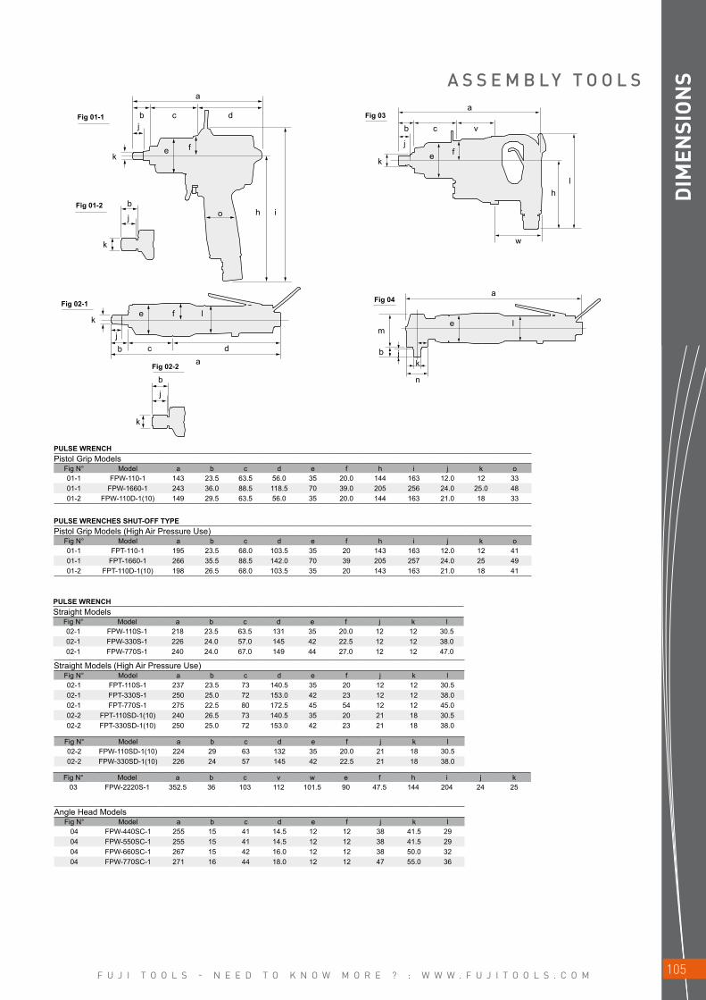
F U J I T O O L S - N E E D T O K N O W M O R E ? : W W W . F U J I T O O L S . C O M 105
a
b
ke f
ob
ba
c d
j
j
e f
b
j
k
l
k
k
h i
jc d
a
b
j
k e f
h
w
l
c v
m
b jk
n
e l
a
DIM
ENSI
ON
SA S S E M B L Y T O O L S
PULSE WRENCHES SHUT-OFF TYPEPistol Grip Models (High Air Pressure Use)
Fig N° Model a b c d e f h i j k o01-1 FPT-110-1 195 23.5 68.0 103.5 35 20 143 163 12.0 12 4101-1 FPT-1660-1 266 35.5 88.5 142.0 70 39 205 257 24.0 25 4901-2 FPT-110D-1(10) 198 26.5 68.0 103.5 35 20 143 163 21.0 18 41
PULSE WRENCHPistol Grip Models
Fig N° Model a b c d e f h i j k o01-1 FPW-110-1 143 23.5 63.5 56.0 35 20.0 144 163 12.0 12 3301-1 FPW-1660-1 243 36.0 88.5 118.5 70 39.0 205 256 24.0 25.0 4801-2 FPW-110D-1(10) 149 29.5 63.5 56.0 35 20.0 144 163 21.0 18 33
Straight Models (High Air Pressure Use)Fig N° Model a b c d e f j k l02-1 FPT-110S-1 237 23.5 73 140.5 35 20 12 12 30.502-1 FPT-330S-1 250 25.0 72 153.0 42 23 12 12 38.002-1 FPT-770S-1 275 22.5 80 172.5 45 54 12 12 45.002-2 FPT-110SD-1(10) 240 26.5 73 140.5 35 20 21 18 30.502-2 FPT-330SD-1(10) 250 25.0 72 153.0 42 23 21 18 38.0
PULSE WRENCHStraight Models
Fig N° Model a b c d e f j k l02-1 FPW-110S-1 218 23.5 63.5 131 35 20.0 12 12 30.502-1 FPW-330S-1 226 24.0 57.0 145 42 22.5 12 12 38.002-1 FPW-770S-1 240 24.0 67.0 149 44 27.0 12 12 47.0
Fig N° Model a b c v w e f h i j k03 FPW-2220S-1 352.5 36 103 112 101.5 90 47.5 144 204 24 25
Fig N° Model a b c d e f j k l02-2 FPW-110SD-1(10) 224 29 63 132 35 20.0 21 18 30.502-2 FPW-330SD-1(10) 226 24 57 145 42 22.5 21 18 38.0
Angle Head ModelsFig N° Model a b c d e f j k l
04 FPW-440SC-1 255 15 41 14.5 12 12 38 41.5 2904 FPW-550SC-1 255 15 41 14.5 12 12 38 41.5 2904 FPW-660SC-1 267 15 42 16.0 12 12 38 50.0 3204 FPW-770SC-1 271 16 44 18.0 12 12 47 55.0 36
Fig 01-1
Fig 02-2
Fig 01-2
Fig 02-1
Fig 03
Fig 04

F U J I T O O L S - N E E D T O K N O W M O R E ? : W W W . F U J I T O O L S . C O M106
b
j
k e f
o h l
c d
a
Fig 02-1m
b jk
n
e l
a
ba
c dj
e f lk
ac
p
s
tu
e
o
q
DIM
ENSI
ON
S
DUAL CHAMBER MOTOR IMPACT WRENCHESPistol Grip Models
Fig N° Model a b c d e f h i j k o06 FW-44PA-2 131.0 23.0 38.0 70.0 39.5 22.5 144.0 166.0 12.0 12 3806 FW-66PA-2 137.0 18.0 49.0 70.0 42.0 22.5 144.0 166.0 12.0 12 3806 FW-88P-1 163.0 22.5 54.0 86.5 50.0 29.0 173.0 211.0 16.5 16 41
IMPACT WRENCHESSmall Pistol Grip Models
Fig N° Model a b c d e f h i j k o06 FW-5PX-6 150.0 14.0 49.0 87.0 34.0 18.0 137.0 155.0 12.0 12.0 36.0 06 FW-6PM-1 140.0 18.0 48.0 74.0 42.0 23.5 145.0 168.0 12.0 12.0 38.0 06 FW-6PL-1 175.0 18.0 52.5 104.5 42.0 27.0 122.0 152.0 12.0 12.0 35.0 06 FW-6PX-5(6) 166.0 15.0 57.0 94.0 44.0 24.0 146.0 172.0 12.0 14.0 40.0 06 FW-6PH-1(11) 147.0 16.5 62.0 68.5 50.0 29.0 162.0 198.0 12.0 14.0 43.0 06 FW-8PH-3 162.0 21.0 65.0 76.0 54.0 29.0 168.0 208.0 16.5 16.0 45.5 06 FW-10PX-5 181.8 20.8 78.0 83.0 55.5 29.0 188.0 229.0 17.0 17.0 44.0 06 FW-10PH-1 179.4 23.9 77.5 78.0 58.0 33.0 171.0 214.0 17.0 17.0 44.3 06 FW-10PH-2 179.0 24.0 77.0 78.0 58.0 31.0 171.0 213.0 16.5 17.0 44.3 06 FW-14PX-5 197.3 21.3 93.0 83.0 66.0 34.5 192.0 237.0 16.5 16.8 50.0 06 FW-14PH-1 202.0 23.0 94.5 84.5 67.0 37.5 181.5 229.5 16.5 16.8 47.6 06 FW-14PH-2 202.0 23.0 94.0 85.0 67.0 37.5 181.0 228.0 16.5 20.0 47.6 06 FW-14PH-3 202.0 23.0 94.0 85.0 67.0 37.5 181.0 228.0 18.5 20.0 47.6
Straight ModelsFig N° Model a b c d e f j k l02-1 FW-44SA-1 197.5 14.5 38 145 39.5 22.5 12 12 3802-1 FW-66SA-1 212.0 18.0 49 145 42.0 22.5 12 12 38
A S S E M B L Y T O O L S
Angle Head Models (High Air Pressure Use)Fig N° Model a b e d e f j k l
04 FPT-440SC-1 281 15.0 41 14.5 12 12 38 41.5 2904 FPT-550SC-1 281 15.0 41 14.5 12 12 38 41.5 2904 FPT-660SC-1 294 15.0 42 16.0 12 12 38 50.0 3204 FPT-770SC-1 307 16.0 50 18.0 12 12 45 55.0 36
Geared Pulse Wrenches Shut-Off TypeFig N° Model a c d e f l o p q r s t u
05 FPT-770SCG-1 378 136 171 50 27 45 15 58 109 38 25 78 90
GEARED PULSE WRENCHESFig N° Model a c d e f l o p q r s t u
05 FPW-770SCG-1 343 124 148 44 27 45 15 58 109 38 25 78 90
Fig 06
Fig 04Fig 02-1
Fig 05
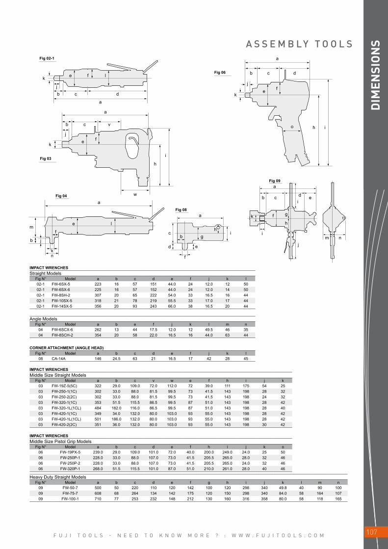
F U J I T O O L S - N E E D T O K N O W M O R E ? : W W W . F U J I T O O L S . C O M 107
k
k
m
b j
nk
f
e
a
c i
d
l
a
a
b c d ei
k f g
h
i
jm n
je
h
i
f
e
jb c d
a
w
a
b c v
a
b
j
ke f
o h i
c df l
b gh
e
f
DIM
ENSI
ON
SA S S E M B L Y T O O L S
IMPACT WRENCHESStraight Models
Fig N° Model a b c d e f j k l02-1 FW-6SX-5 223 16 57 151 44.0 24 12.0 12 5002-1 FW-6SX-6 225 16 57 152 44.0 24 12.0 14 5002-1 FW-8SH-2 307 20 65 222 54.0 33 16.5 16 4402-1 FW-10SX-5 318 21 78 219 55.5 33 17.0 17 4402-1 FW-14SX-5 356 20 93 243 66.0 38 16.5 20 44
IMPACT WRENCHESMiddle Size Straight Models
Fig N° Model a b c v w e f h i j k03 FW-19Z-5(5C) 322 29.0 109.0 72.0 112.0 72 39.0 111 175 54 2503 FW-250-1(1C) 302 33.0 88.0 81.5 99.5 73 41.5 143 198 28 3203 FW-250-2(2C) 302 33.0 88.0 81.5 99.5 73 41.5 143 198 24 3203 FW-320-1(1C) 353 51.5 115.5 86.5 99.5 87 51.0 143 198 28 4203 FW-320-1L(1CL) 484 182.0 116.0 86.5 99.5 87 51.0 143 198 28 4003 FW-420-1(1C) 349 34.0 132.0 80.0 103.0 93 55.0 143 198 28 4203 FW-420-1L(1CL) 501 186.0 132.0 80.0 103.0 93 55.0 143 198 28 4203 FW-420-2(2C) 351 36.0 132.0 80.0 103.0 93 55.0 143 198 30 42
IMPACT WRENCHESMiddle Size Pistol Grip Models
Fig N° Model a b c d e f h i j k o06 FW-19PX-5 239.0 29.0 109.0 101.0 72.0 40.0 200.0 249.0 24.0 25 50 06 FW-250P-1 228.0 33.0 88.0 107.0 73.0 41.5 205.5 265.0 28.0 32 46 06 FW-250P-2 228.0 33.0 88.0 107.0 73.0 41.5 205.5 265.0 24.0 32 46 06 FW-320P-1 268.0 51.5 115.5 101.0 87.0 51.0 210.0 261.0 28.0 40 46
Heavy Duty Straight ModelsFig N° Model a b c d e f g h i j k l m n
09 FW-50-7 500 50 220 110 120 142 100 120 298 340 49.8 40 90 10009 FW-75-7 608 68 264 134 142 175 120 150 298 340 84.0 58 164 10709 FW-100-1 710 77 253 232 148 212 130 160 316 358 80.0 58 118 165
CORNER ATTACHMENT (ANGLE HEAD)Fig N° Model a b c d e f j k l
08 CA-14A 146 24.5 63 21 16.5 17 42 28 45
Angle ModelsFig N° Model a b e f j k l m n
04 FW-6SCX-6 262 13 44 17.5 12.0 12 49.5 46 3504 FW-8SCH-2 354 20 58 22.0 16.5 16 44.0 63 44
Fig 02-1
Fig 03
Fig 06
Fig 04
Fig 08
Fig 09

F U J I T O O L S - N E E D T O K N O W M O R E ? : W W W . F U J I T O O L S . C O M108
k
e
a
a
a
c d
v
z w
aa ab y
b
e
kj
c d
b c d
e
jb c d
a
f l
ïf g h i
f g h
le f l
x
a
bj
ke f
o h i
c d
DIM
ENSI
ON
S
IMPACT WRENCHESImpact Clutch TypeStraight Models
Fig N° Model a b c d e f j k l02-2 FW-5SXD-7(70) 223 24 50 149 34 18 21 18 33.002-2 FW-5SXD-8(80) 194 27 50 117 34 18 21 18 33.002-2 FW-6SXD-6(60) 235 27 57 151 44 24 21 18 49.5
Pistol Grip ModelsFig N° Model a b c d e f h i j k o06-2 FW-5PXD-6(60) 160 24.0 49.5 86.5 34 18.0 137 155 21 18 3606-2 FW-6PMD-1(10) 146 24.0 48.0 74.0 42 23.5 145 168 21 18 3806-2 FW-6PLD-1 180 23.5 52.5 104.0 42 30.0 122 152 20 19 3506-2 FW-6PXD-6(60) 177 27.0 57.0 93.0 44 24.0 146 181 21 18 4006-2 FW-6PHD-1 154 24.0 62.0 68.0 50 29.0 162 198 21 19 43
Fig N° Model a b c d e f j k l02-2 FW-44SAD-1(10) 207 24 38 145 39.5 22.5 21 18 3802-2 FW-66SAD-1(10) 218 24 49 145 42.0 22.5 21 18 38
Fig N° Model a b c d e f h i j k o06-2 FW-44PAD-2(20) 132.0 24 38.0 70 39.5 22.5 144 166 21 18 3806-2 FW-66PAD-2(20) 143.0 24 49.0 70 42.0 22.5 144 166 21 18 38
Slip Clutch TypeStraight Models
Fig N° Model a b c d e f g h i10 FD-4 174 38.5 64 71.5 7.4 25 26 37 3210 FD-5 233 45.0 92 96.0 7.4 25 32 42 38
Pistol Grip ModelsFig N° Model a b c d e f g h j k l
11 FD-4P 173 39 64 70 7.4 25 26 37 125 143 4211 FD-5P 210 45 92 73 7.4 25 32 42 130 150 42
RATCHET WRENCHESFig N° Model a c d e f l v w x y z aa ab
12 FRW-6NX-3(3A) 316.0 182.0 134 38.6 21.5 32 20 13(10) 13(10) 88.0 20.2(15.2) 10.0 28.012 FRW-6NX-4(4A) 320.0 186.0 134 38.6 21.5 32 24 13(10) 13(10) 92.7 20.2(15.2) 12.0 30.712 FRW-8NX-2(2A) 380.0 217.0 163 46.0 25.0 48 25 18(10) 16(10) 108.0 25.5(15.2) 12.5 32.012 FRW-10N-2 417.0 228.0 189 46.0 29.0 32 33 18 16 115.0 25.5 16.5 37.512 FRW-13N-3 418.5 229.5 189 46.0 29.0 32 36 18 16 116.0 25.5 18.0 37.512 FRW-13N-4 431.0 242.0 189 46.0 29.0 32 46 18 16 129.0 25.5 23.0 45.0
A S S E M B L Y T O O L S
Fig 02-2
Fig 10
Fig 11 Fig 12
Fig 06-2

F U J I T O O L S - N E E D T O K N O W M O R E ? : W W W . F U J I T O O L S . C O M 109
a
a
a
b
g
c d e f
b
b c1 c2 d
k
k
c d
e2 e3
h
e2
a
b
k
c1 c2 d
d
e3
i j
a
a
b
b
k g
ef
j
ih
c d
k g h i j
c d e
e1 e2 e3
e1 e2 e3
a
a
c2b1
k
b c1
k
d
bb1
k
c1 c2 d
e1
me1 e2 e3 e4
DIM
ENSI
ON
SA B R A S I V E T O O L S
PENCIL GRINDERSFig N° Model a b c d e2 e3 k
14 FG-06-1 153 11 90 52 14.5 16 9.5
TURBO GRINDERSFig N° Model a b c d e f g h i j
15 TURBO-100 153 28 70 18 9.0 28 9.5 29 31 2915 TURBO-100A 155 30 70 18 9.0 28 16.0 29 31 29
Fig N° Model a b c d e f g h i15 bis FG-13-2 149.5 27.0 42.0 35.0 45.5 30.5 29 33 9.515 bis FG-13-20 149.5 44.0 25.5 35.0 45.5 30.5 29 33 9.515 bis FG-13X-2 179.0 27.0 42.0 35.5 74.5 30.5 29 30 9.515 bis FG-13X-20 179.0 44.0 25.5 35.5 74.5 30.5 29 30 9.5
DIE GRINDERSFig N° Model a b c d e f g h i
16 FG-12U-1(F) 188.0 28.5 48.0 101.5 10.0 36.0 35 34.0 17.016 FG-13-1(F) 158.0 27.0 42.0 76.0 13.0 30.5 32 32.0 9.516 FG-13-10(F) 158.0 43.5 25.5 76.0 13.0 30.5 32 32.0 9.516 FG-25D-1(F) 198.0 28.0 52.0 108.0 10.0 38.5 39 38.0 17.016 FG-50D-1(F) 210.0 28.0 51.0 121.0 10.0 40.5 41 40.0 17.016 FG-12UX-1(F) 213.0 28.0 40.0 111.0 34.0 35.5 36 34.0 17.016 FG-13X-1(F) 183.0 27.0 42.0 83.5 30.5 30.5 32 32.0 9.516 FG-13X-10(F) 183.0 43.5 25.5 83.5 30.5 30.5 32 32.0 9.516 FG-25DX-1(F) 231.0 28.0 50.0 119.0 34.0 38.5 39 34.0 17.016 FG-50DX-1(F) 243.0 26.0 52.5 129.0 35.5 40.5 41 34.0 17.0
16 bis FG-12U-2 191 28.5 47.5 79.5 35.5 36.0 35 33.0 1716 bis FG-25D-2 202 28.0 54.5 84.0 35.5 38.5 39 33.0 3016 bis FG-50D-2 213 28.0 51.0 98.5 35.5 40.5 41 37.0 1716 bis FG-12UX-2 211 29.0 40.0 54.0 88.0 36.0 36 30.5 1716 bis FG-25DX-2 227 28.0 50.0 61.0 88.0 38.5 36 30.5 1716 bis FG-50DX-2 237 26.5 52.5 72.0 86.0 40.5 42 30.5 17
DIE GRINDERSFig N° Model a b c d e f g h i j k
17 FG-50-25 187 44 34.5 53.5 57 16 39.5 36 38 33 16
DIE GRINDERSFig N° Model a b c d e f g h i j k
18 FG-25T 76 14 17.5 44.5 14 21 39 80 54 7.5 17Hex
Extension Type ModelsFig N° Model a b1 b c1 c2 d e1 e2 e3 k
22 FG-3HA-1 316 18 70.5 23 150.8 71.7 27 48 32 17Hex
Fig N° Model a b1 b c1 c2 d e1 e2 e3 k22 FG-3HA-2 316 18 70.5 23 150.8 71.7 27 48 32 17Hex
Fig N° Model a b1 b c1 c2 d e1 e2 e3 e4 k l m23 FG-3H-6 329 14 56 24 148 101 32 27 48 32.0 17Hex 29.3 41.023 FG-4VA-1 385 14 53 31 203 98 38 34 52 38.5 17Hex 30.0 45.523 FG-4VA-2 391 17 59 31 203 98 38 34 52 38.5 21Hex 31.0 58.5
Fig 14
Fig 15
Fig 15 bis
Fig 16
Fig 16 bis
Fig 17
Fig 18
Fig 22
Fig 23
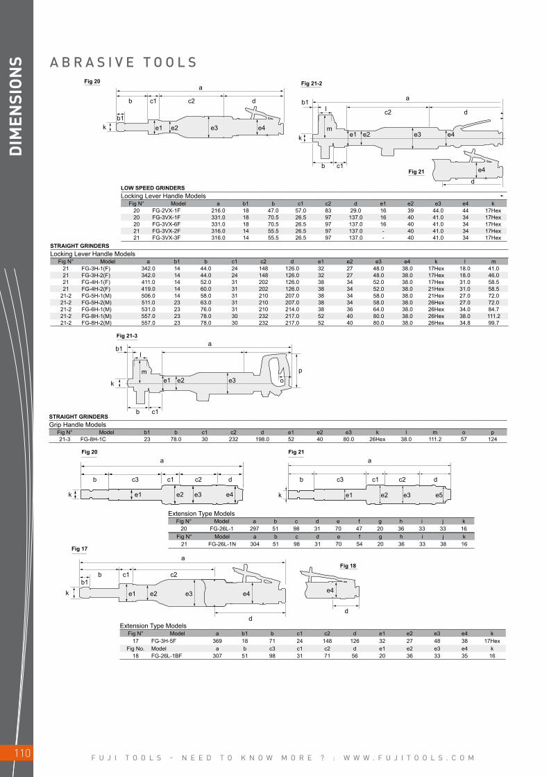
F U J I T O O L S - N E E D T O K N O W M O R E ? : W W W . F U J I T O O L S . C O M110
b1
b c1
k e1 e2 e3 op
a
l
m
b
kk
b1l
b1
c1 c2 d
e1 e2 e3 e4 m
b c1
e1 e2 e3
d
c2
aa
d
e4
e4
a a
b b c3 c1 c2 d
k
c3 c1 c2 d
ke1 e2 e3 e4 e1 e2 e3 e5
a
kb1
b c1 c2
dd
É Qe1 e2 e3 e4 e4
DIM
ENSI
ON
S A B R A S I V E T O O L S
STRAIGHT GRINDERSGrip Handle Models
Fig N° Model b1 b c1 c2 d e1 e2 e3 k l m o p 21-3 FG-8H-1C 23 78.0 30 232 198.0 52 40 80.0 26Hex 38.0 111.2 57 124
LOW SPEED GRINDERSLocking Lever Handle Models
Fig N° Model a b1 b c1 c2 d e1 e2 e3 e4 k20 FG-2VX-1F 216.0 18 47.0 57.0 83 29.0 16 39 44.0 44 17Hex20 FG-3VX-1F 331.0 18 70.5 26.5 97 137.0 16 40 41.0 34 17Hex20 FG-3VX-6F 331.0 18 70.5 26.5 97 137.0 16 40 41.0 34 17Hex21 FG-3VX-2F 316.0 14 55.5 26.5 97 137.0 - 40 41.0 34 17Hex21 FG-3VX-3F 316.0 14 55.5 26.5 97 137.0 - 40 41.0 34 17Hex
STRAIGHT GRINDERSLocking Lever Handle Models
Fig N° Model a b1 b c1 c2 d e1 e2 e3 e4 k l m21 FG-3H-1(F) 342.0 14 44.0 24 148 126.0 32 27 48.0 38.0 17Hex 18.0 41.021 FG-3H-2(F) 342.0 14 44.0 24 148 126.0 32 27 48.0 38.0 17Hex 18.0 46.021 FG-4H-1(F) 411.0 14 52.0 31 202 126.0 38 34 52.0 38.0 17Hex 31.0 58.521 FG-4H-2(F) 419.0 14 60.0 31 202 126.0 38 34 52.0 38.0 21Hex 31.0 58.5
21-2 FG-5H-1(M) 506.0 14 58.0 31 210 207.0 38 34 58.0 38.0 21Hex 27.0 72.021-2 FG-5H-2(M) 511.0 23 63.0 31 210 207.0 38 34 58.0 38.0 26Hex 27.0 72.021-2 FG-6H-1(M) 531.0 23 76.0 31 210 214.0 38 36 64.0 38.0 26Hex 34.0 84.721-2 FG-8H-1(M) 557.0 23 78.0 30 232 217.0 52 40 80.0 38.0 26Hex 38.0 111.221-2 FG-8H-2(M) 557.0 23 78.0 30 232 217.0 52 40 80.0 38.0 26Hex 34.8 99.7
Extension Type ModelsFig N° Model a b c d e f g h i j k
20 FG-26L-1 297 51 98 31 70 47 20 36 33 33 16Fig N° Model a b c d e f g h i j k
21 FG-26L-1N 304 51 98 31 70 54 20 36 33 38 16
Extension Type ModelsFig N° Model a b1 b c1 c2 d e1 e2 e3 e4 k
17 FG-3H-5F 369 18 71 24 148 126 32 27 48 38 17HexFig No. Model a b c3 c1 c2 d e1 e2 e3 e4 k
18 FG-26L-1BF 307 51 98 31 71 56 20 36 33 35 16
Fig 21-3
Fig 20 Fig 21-2
Fig 21
Fig 20 Fig 21
Fig 17
Fig 18

F U J I T O O L S - N E E D T O K N O W M O R E ? : W W W . F U J I T O O L S . C O M 111
aa
a
l
k
b1b
l
lc2 d
c3 c1 c2 dc3 c1 c2 d
e1 e2 e3 e4m mk
k
e1 e2 e3 e4
b1
b1
e1 e2 e3 e4
c1
b
b
a
a
c2 d
d
b1
b1
k
b c1
me1 e2
c2 d
a
e3 e4
l
k
k
b1
b1b
m
l
e1
c3 c1 c2 d
e2 e3 e4
e4
me1 e2 e3 e4
c1
DIM
ENSI
ON
S
Extension Type ModelsFig N° Model a b1 b c3 c1 c2 d e1 e2 e3 e4 k l m
24 FG-50L-1(A) 307.5 8 36.0 91 29 103.5 48 23 39.5 36 37 17Hex 22 3224 FG-50Y-1(A) 523.0 8 36.5 306 29 103.5 48 23 39.5 36 37 17Hex 22 32
Fig N° Model a b1 b c3 c1 c2 d e1 e2 e3 e4 k l m25 FG-3HL-1(A) 522 14 43 252 21 105 101 23 40 48 32 17Hex 22.5 40.525 FG-3HY-1(A) 702 14 43 405 21 104 102 23 40 48 32 17Hex 22.5 40.5
Fig N° Model a b1 b c1 c2 d e1 e2 e3 e4 k l m26 FG-4HL-1(A) 585.0 14.0 50 22 415.0 98 27 34 52 38.5 17Hex 30 45.526 FG-5HL-1(A) 957.5 17.0 63 24 764.5 106 46 34 58 38.5 17Hex 30 43.526 FG-5HL-2(A) 953.0 14.0 63 24 760.0 106 36 34 58 38.5 17Hex 31 58.526 FG-5HL-11(A) 599.0 16.0 50 22 418.5 108 27 34 58 38.0 19Hex 30 45.526 FG-5HL-13(A) 599.0 16.5 50 23 418.5 108 27 34 58 38.0 19Hex 31 56.526 FG-5HL-14 599.0 16.5 50 23 418.5 108 27 34 58 38 19Hex 31 56.5
A B R A S I V E T O O L S
EXTENDED GRINDERSLocking Lever Handle Models
Fig N° Model a b1 b c3 c1 c2 d e1 e2 e3 e4 k l m23 FG-50L-1BF 316.5 8 36.0 91 29 103.5 57 23 39.5 36 39 17Hex 22.0 32.023 FG-50Y-1BF 532.0 8 36.5 306 29 103.5 57 23 39.5 36 39 17Hex 22.0 32.023 FG-3HL-1F 547.0 14 43.0 252 21 105.0 126 23 40.0 48 38 17Hex 22.5 40.5
Fig N° Model a b1 b c3 c1 c2 d e1 e2 e3 e4 k l21-4 FG-4HL-1F 613.0 14 50.0 22 415 126.0 27 34 52.0 38 17Hex 33 45.521-2 FG-5HL-2M 1055.0 14 63.0 24 760 208.0 36 34 58.0 38 21Hex 31 58.5
Fig 24 Fig 25
Fig 26
Fig 21-2
Fig 21-4
Fig 21
Fig 23
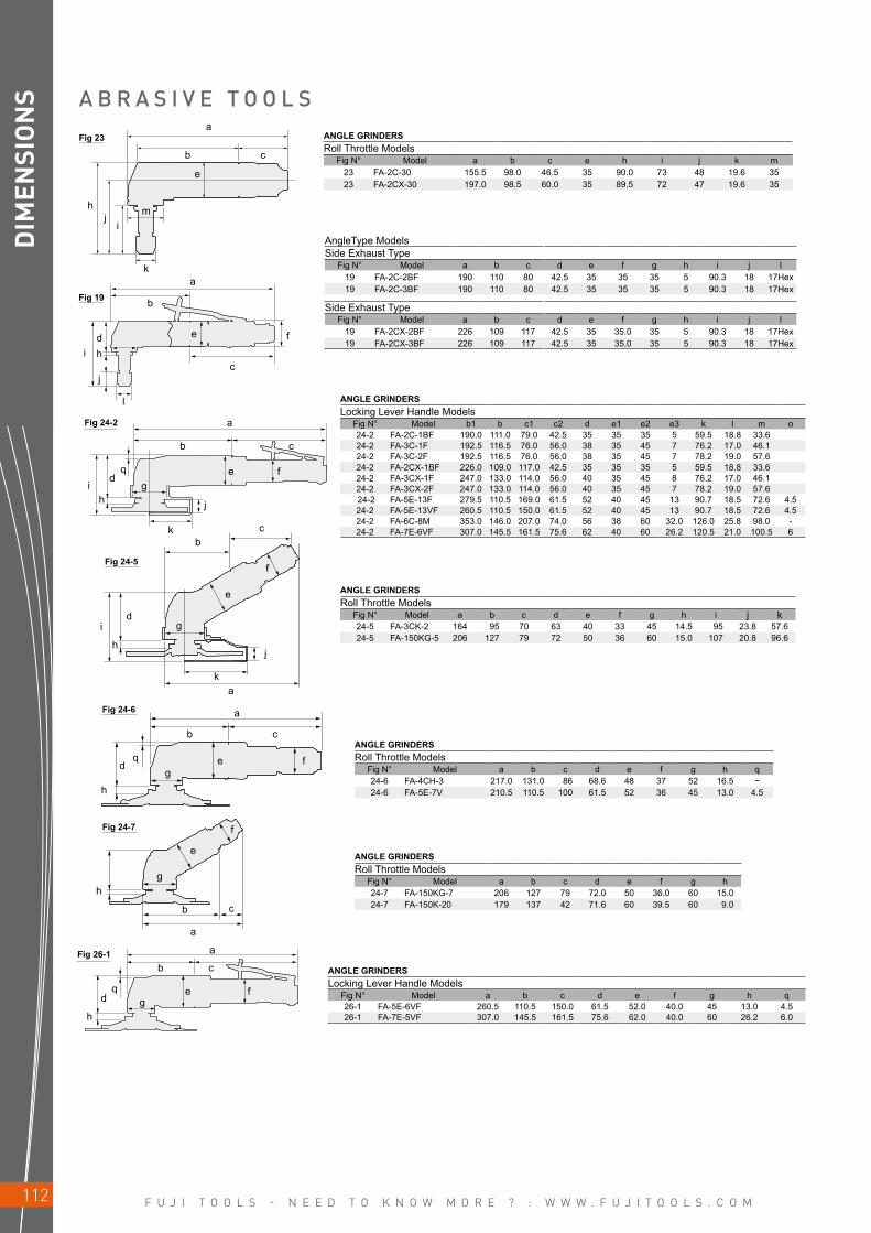
F U J I T O O L S - N E E D T O K N O W M O R E ? : W W W . F U J I T O O L S . C O M112
a
b c
k
a
b c
qd
h
ih
dq fe
j
g
ge f
cb
i
h
h
h
a
b c
d
j
g
ka
a
b
qd
ge f
c
f
e
g
e
f
a
hj
i
b c
m
k
e
id e f
h
j
l
a
b
c
DIM
ENSI
ON
S
ANGLE GRINDERSLocking Lever Handle Models
Fig N° Model b1 b c1 c2 d e1 e2 e3 k l m o24-2 FA-2C-1BF 190.0 111.0 79.0 42.5 35 35 35 5 59.5 18.8 33.624-2 FA-3C-1F 192.5 116.5 76.0 56.0 38 35 45 7 76.2 17.0 46.124-2 FA-3C-2F 192.5 116.5 76.0 56.0 38 35 45 7 78.2 19.0 57.624-2 FA-2CX-1BF 226.0 109.0 117.0 42.5 35 35 35 5 59.5 18.8 33.624-2 FA-3CX-1F 247.0 133.0 114.0 56.0 40 35 45 8 76.2 17.0 46.124-2 FA-3CX-2F 247.0 133.0 114.0 56.0 40 35 45 7 78.2 19.0 57.6 24-2 FA-5E-13F 279.5 110.5 169.0 61.5 52 40 45 13 90.7 18.5 72.6 4.524-2 FA-5E-13VF 260.5 110.5 150.0 61.5 52 40 45 13 90.7 18.5 72.6 4.524-2 FA-6C-8M 353.0 146.0 207.0 74.0 56 38 60 32.0 126.0 25.8 98.0 -24-2 FA-7E-6VF 307.0 145.5 161.5 75.6 62 40 60 26.2 120.5 21.0 100.5 6
ANGLE GRINDERSLocking Lever Handle Models
Fig N° Model a b c d e f g h q26-1 FA-5E-6VF 260.5 110.5 150.0 61.5 52.0 40.0 45 13.0 4.526-1 FA-7E-5VF 307.0 145.5 161.5 75.6 62.0 40.0 60 26.2 6.0
ANGLE GRINDERSRoll Throttle Models
Fig N° Model a b c d e f g h i j k24-5 FA-3CK-2 164 95 70 63 40 33 45 14.5 95 23.8 57.624-5 FA-150KG-5 206 127 79 72 50 36 60 15.0 107 20.8 96.6
ANGLE GRINDERSRoll Throttle Models
Fig N° Model a b c d e f g h q24-6 FA-4CH-3 217.0 131.0 86 68.6 48 37 52 16.5 −24-6 FA-5E-7V 210.5 110.5 100 61.5 52 36 45 13.0 4.5
ANGLE GRINDERSRoll Throttle Models
Fig N° Model a b c d e f g h24-7 FA-150KG-7 206 127 79 72.0 50 36.0 60 15.024-7 FA-150K-20 179 137 42 71.6 60 39.5 60 9.0
A B R A S I V E T O O L SANGLE GRINDERSRoll Throttle Models
Fig N° Model a b c e h i j k m23 FA-2C-30 155.5 98.0 46.5 35 90.0 73 48 19.6 3523 FA-2CX-30 197.0 98.5 60.0 35 89.5 72 47 19.6 35
AngleType ModelsSide Exhaust Type
Fig N° Model a b c d e f g h i j l19 FA-2C-2BF 190 110 80 42.5 35 35 35 5 90.3 18 17Hex19 FA-2C-3BF 190 110 80 42.5 35 35 35 5 90.3 18 17Hex
Side Exhaust TypeFig N° Model a b c d e f g h i j l
19 FA-2CX-2BF 226 109 117 42.5 35 35.0 35 5 90.3 18 17Hex19 FA-2CX-3BF 226 109 117 42.5 35 35.0 35 5 90.3 18 17Hex
Fig 24-2
Fig 26-1
Fig 24-5
Fig 24-6
Fig 24-7
Fig 23
Fig 19

F U J I T O O L S - N E E D T O K N O W M O R E ? : W W W . F U J I T O O L S . C O M 113
a
b
i dq
h
c
g
k
j
e f
hf
ac2
i ej
a
b
bb
c
ea
dg
c
c d
c1b
e
a
h
f
m
d
e
f
g
lk
ji
b c
f
g h
hf
ea
f gh
DIM
ENSI
ON
S
ANGLE GRINDERSRoll Throttle Models
Fig N° Model a b c d e f g h i j k24 FA-4C-1 212 111 101 69.0 48 32 52 8 95 14.8 57.624 FA-4C-3 212 110 103 69.0 48 37 52 8 95 14.8 57.624 FA-6C-1 252 146 106 74.0 56 38 60 15 108 20.8 96.624 FA-6C-7 252 146 106 74.0 56 38 60 18 108 17.8 84.124 FA-7C-1 263 143 120 74.0 63 42 60 15 109 17.8 96.624 FA-9C-1 305 166 139 80.0 69 42 60 15 114 20.0 110.024 FA-9C-6 305 166 139 80.0 69 42 60 17 117 21.0 122.0
Fig N° Model a b c d e f g h i j k q24 FA-5E-1V 210.5 110.5 100.0 61.5 52 36 45 13.0 90.7 18.5 72.6 4.524 FA-5E-3V 210.5 110.5 100.0 61.5 52 36 45 13.0 90.2 19.0 57.6 4.524 FA-5E-11V 210.0 109.0 101.0 63.0 52 36 45 10.5 96.0 19.0 100.5 4.524 FA-7E-2V 266.0 145.5 120.5 75.6 62 42 60 17.0 110.5 21.0 100.5 6.0
Fig N° Model a b c d e f g h i j k q24 FA-7E-4V 305 135 163 77.5 62 42 60 20 112.5 19 95.8 6
A B R A S I V E T O O L S
DISC SANDERSFig N° Model a b c1 c2 e f g h
28 FG-5PX-10 108.0 21.0 24.0 63.0 50.0 25.0 41 147.0
VERTICAL GRINDERSStandard Type
Fig N° Model a b c d e f g h i j k l29-1 FV-7-1M 247.0 100.0 147.0 63.0 94.4 26.2 64 201.0 46 38 22.0 96.629-1 FV-7-4M 247.0 100.0 147.0 63.0 94.4 26.2 64 201.0 46 38 22.0 96.629-1 FV-9BH-1M 266.0 127.5 138.5 69.0 119.0 50.2 69 238.2 46 38 30.0 122.0
Cup Wheel TypeFig N° Model a b c d e f g h i j l m29-3 FV-9BH-4M 266.0 127.5 138.5 69.0 119.0 76 69 264.0 46 38 88.4 56~85
Sanding Disc TypeFig N° Model a b c d e f g i j29-2 FV-7-2M 247.0 100.0 147.0 63.0 94.4 38 64 46 38
BELT SANDERSFig N° Model a b c d e f g h i j
30 FBS-1-1 281 87 84 110 10 51 35 121 18 45.230 FBS-1-2 375 181 84 110 20 51 35 121 22 45.230 FBS-1-3 345 151 84 110 13 51 35 121 18 45.230 FBS-1-4 345 151 84 110 20 51 35 121 22 45.2
ORBITAL SANDERSLocking Lever Handle Models
Fig N° Model a b c d e f g h31 DA-125L-E(-M) 172 142 33 97 125 - 45 2631 DA-125C-E(-M) 172 142 33 117 125 - 45 2631 FOR-125B-E(-M) 259 216 35 122 125 42 69 2631 FOR-150B-E(-M) 276 124 35 122 150 42 68 2631 FOR-125BF-E(-M) 259 216 35 122 125 42 69 2631 FOR-150BF-E(-M) 276 124 35 122 150 42 68 2632 FOS-175BF-E(-M) 285 216 35 130 100X175 42 69 2632 FOS-230BF-E 312 217 35 132 100X230 42 68 2632 FOS-400BF-E 400 211 32 138 100X400 43 66 26
Fig 24
Fig 28
Fig 30
Fig 31Fig 32
Fig 29-1 Fig 29-2
Fig 29-3
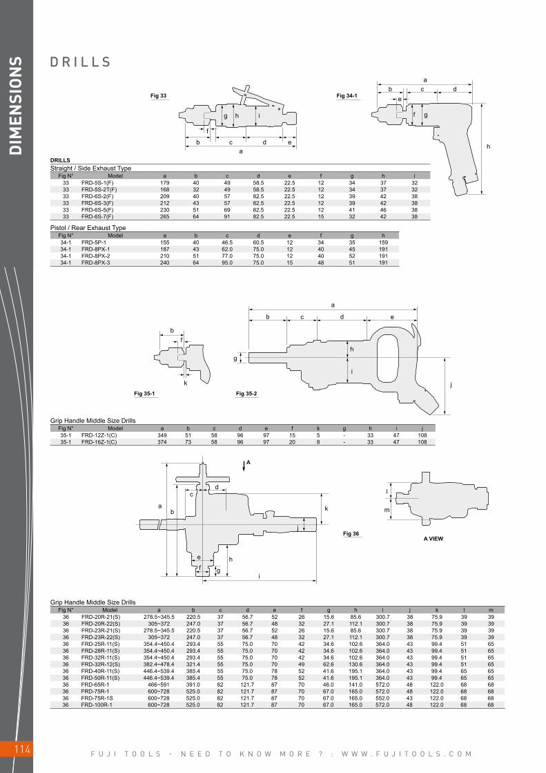
F U J I T O O L S - N E E D T O K N O W M O R E ? : W W W . F U J I T O O L S . C O M114
A
a
b
a k m
l
b
cd
a
b
g
c d e
k
f
a
h
f
eb c d
g
b c d e
f
g h i
h
i
j
e
f g
h
i
j
DIM
ENSI
ON
S
DRILLSStraight / Side Exhaust Type
Fig N° Model a b c d e f g h i33 FRD-5S-1(F) 179 40 49 58.5 22.5 12 34 37 3233 FRD-5S-2T(F) 168 32 49 58.5 22.5 12 34 37 3233 FRD-6S-2(F) 209 40 57 82.5 22.5 12 39 42 3833 FRD-6S-3(F) 212 43 57 82.5 22.5 12 39 42 3833 FRD-6S-5(F) 230 51 69 82.5 22.5 12 41 46 3833 FRD-6S-7(F) 265 64 91 82.5 22.5 15 32 42 38
Pistol / Rear Exhaust TypeFig N° Model a b c d e f g h34-1 FRD-5P-1 155 40 46.5 60.5 12 34 35 15934-1 FRD-8PX-1 187 43 62.0 75.0 12 40 45 19134-1 FRD-8PX-2 210 51 77.0 75.0 12 40 52 19134-1 FRD-8PX-3 240 64 95.0 75.0 15 48 51 191
Grip Handle Middle Size DrillsFig N° Model a b c d e f k g h i j35-1 FRD-12Z-1(C) 349 51 58 96 97 15 5 - 33 47 10835-1 FRD-16Z-1(C) 374 73 58 96 97 20 8 - 33 47 108
Grip Handle Middle Size DrillsFig N° Model a b c d e f g h i j k l m
36 FRD-20R-21(S) 278.5~345.5 220.5 37 56.7 52 26 15.6 85.6 300.7 38 75.9 39 3936 FRD-20R-22(S) 305~372 247.0 37 56.7 48 32 27.1 112.1 300.7 38 75.9 39 3936 FRD-23R-21(S) 278.5~345.5 220.5 37 56.7 52 26 15.6 85.6 300.7 38 75.9 39 3936 FRD-23R-22(S) 305~372 247.0 37 56.7 48 32 27.1 112.1 300.7 38 75.9 39 3936 FRD-25R-11(S) 354.4~450.4 293.4 55 75.0 70 42 34.6 102.6 364.0 43 99.4 51 6536 FRD-28R-11(S) 354.4~450.4 293.4 55 75.0 70 42 34.6 102.6 364.0 43 99.4 51 6536 FRD-32R-11(S) 354.4~450.4 293.4 55 75.0 70 42 34.6 102.6 364.0 43 99.4 51 6536 FRD-32R-12(S) 382.4~478.4 321.4 55 75.0 70 49 62.6 130.6 364.0 43 99.4 51 6536 FRD-40R-11(S) 446.4~539.4 385.4 55 75.0 78 52 41.6 195.1 364.0 43 99.4 65 6536 FRD-50R-11(S) 446.4~539.4 385.4 55 75.0 78 52 41.6 195.1 364.0 43 99.4 65 6536 FRD-65R-1 466~591 391.0 82 121.7 87 70 46.0 141.0 572.0 48 122.0 68 6836 FRD-75R-1 600~728 525.0 82 121.7 87 70 67.0 165.0 572.0 48 122.0 68 6836 FRD-75R-1S 600~728 525.0 82 121.7 87 70 67.0 165.0 552.0 43 122.0 68 6836 FRD-100R-1 600~728 525.0 82 121.7 87 70 67.0 165.0 572.0 48 122.0 68 68
D R I L L S
Fig 33
Fig 35-1 Fig 35-2
Fig 34-1
Fig 36A VIEW
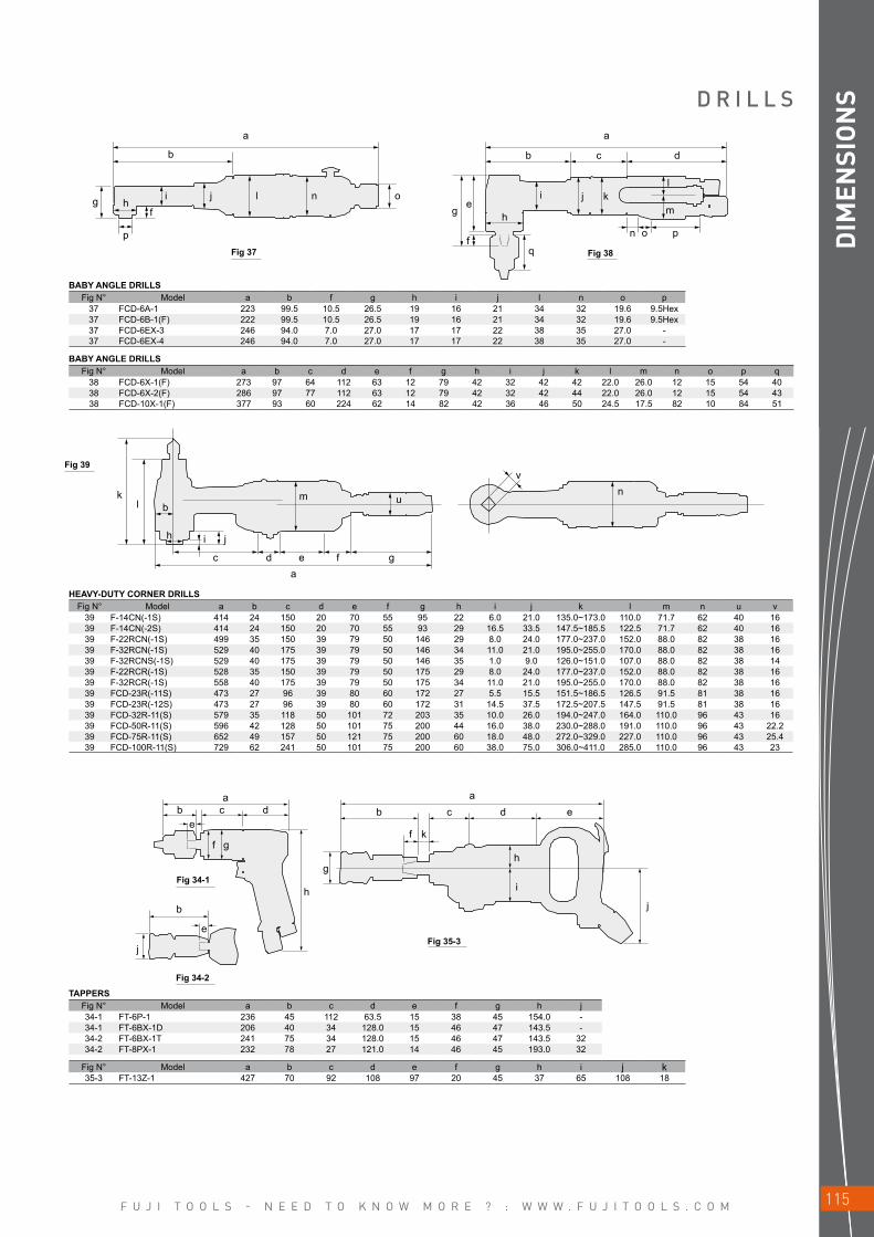
F U J I T O O L S - N E E D T O K N O W M O R E ? : W W W . F U J I T O O L S . C O M 115
a a
b
g
f
e
c db
g
p
kl
hf
i j l n o
h
q
i j kl
m
n o p
b
h i j
c
a a
b
h
g
f k
e
b b c d ec
j
de
ad e
m u
vn
f g
f gh
i
j
DIM
ENSI
ON
SD R I L L S
BABY ANGLE DRILLSFig N° Model a b f g h i j l n o p
37 FCD-6A-1 223 99.5 10.5 26.5 19 16 21 34 32 19.6 9.5Hex37 FCD-6B-1(F) 222 99.5 10.5 26.5 19 16 21 34 32 19.6 9.5Hex37 FCD-6EX-3 246 94.0 7.0 27.0 17 17 22 38 35 27.0 -37 FCD-6EX-4 246 94.0 7.0 27.0 17 17 22 38 35 27.0 -
BABY ANGLE DRILLSFig N° Model a b c d e f g h i j k l m n o p q
38 FCD-6X-1(F) 273 97 64 112 63 12 79 42 32 42 42 22.0 26.0 12 15 54 4038 FCD-6X-2(F) 286 97 77 112 63 12 79 42 32 42 44 22.0 26.0 12 15 54 4338 FCD-10X-1(F) 377 93 60 224 62 14 82 42 36 46 50 24.5 17.5 82 10 84 51
HEAVY-DUTY CORNER DRILLSFig N° Model a b c d e f g h i j k l m n u v
39 F-14CN(-1S) 414 24 150 20 70 55 95 22 6.0 21.0 135.0~173.0 110.0 71.7 62 40 1639 F-14CN(-2S) 414 24 150 20 70 55 93 29 16.5 33.5 147.5~185.5 122.5 71.7 62 40 1639 F-22RCN(-1S) 499 35 150 39 79 50 146 29 8.0 24.0 177.0~237.0 152.0 88.0 82 38 1639 F-32RCN(-1S) 529 40 175 39 79 50 146 34 11.0 21.0 195.0~255.0 170.0 88.0 82 38 1639 F-32RCNS(-1S) 529 40 175 39 79 50 146 35 1.0 9.0 126.0~151.0 107.0 88.0 82 38 1439 F-22RCR(-1S) 528 35 150 39 79 50 175 29 8.0 24.0 177.0~237.0 152.0 88.0 82 38 1639 F-32RCR(-1S) 558 40 175 39 79 50 175 34 11.0 21.0 195.0~255.0 170.0 88.0 82 38 1639 FCD-23R(-11S) 473 27 96 39 80 60 172 27 5.5 15.5 151.5~186.5 126.5 91.5 81 38 1639 FCD-23R(-12S) 473 27 96 39 80 60 172 31 14.5 37.5 172.5~207.5 147.5 91.5 81 38 1639 FCD-32R-11(S) 579 35 118 50 101 72 203 35 10.0 26.0 194.0~247.0 164.0 110.0 96 43 1639 FCD-50R-11(S) 596 42 128 50 101 75 200 44 16.0 38.0 230.0~288.0 191.0 110.0 96 43 22.239 FCD-75R-11(S) 652 49 157 50 121 75 200 60 18.0 48.0 272.0~329.0 227.0 110.0 96 43 25.439 FCD-100R-11(S) 729 62 241 50 101 75 200 60 38.0 75.0 306.0~411.0 285.0 110.0 96 43 23
TAPPERSFig N° Model a b c d e f g h j34-1 FT-6P-1 236 45 112 63.5 15 38 45 154.0 -34-1 FT-6BX-1D 206 40 34 128.0 15 46 47 143.5 -34-2 FT-6BX-1T 241 75 34 128.0 15 46 47 143.5 3234-2 FT-8PX-1 232 78 27 121.0 14 46 45 193.0 32
Fig N° Model a b c d e f g h i j k35-3 FT-13Z-1 427 70 92 108 97 20 45 37 65 108 18
Fig 39
Fig 34-1
Fig 34-2
Fig 35-3
Fig 37 Fig 38
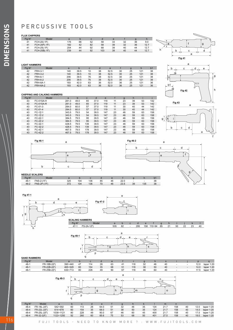
F U J I T O O L S - N E E D T O K N O W M O R E ? : W W W . F U J I T O O L S . C O M116
gfe
b
b
g j
b c de
f
d ec
dca
a
a
a
a
a
ab
f
qp
c d e l n
b
f
qp
c d e r
b
f g
h
d e
e
a
b
b c d
c d
h
g
h
b1
e f e f
g h
jk
l l
g h s
g h k m o
h i
DIM
ENSI
ON
S
FLUX CHIPPERSFig N° Model a b c d e f g h
41 FCH-20(-1F) 176 66 52 58 33 32 36 9.041 FCH-20F(-1F) 182 42 82 58 39 32 36 12.741 FCH-25(-1F) 204 44 92 68 39 40 44 12.741 FCH-25B(-1F) 239 44 92 103 39 40 44 12.7
LIGHT HAMMERSFig N° Model a b c d e f g h b1
42 FRH-3-1 140 39.5 10 38 52.5 30 25 121 3842 FRH-3-2 140 39.5 10 38 52.5 30 25 121 3842 FRH-6-1 206 39.5 76 38 52.5 30 25 121 3842 FRH-6-2 206 39.5 76 38 52.5 30 25 121 3842 FRH-6A-1 193 42.0 63 36 52.0 36 25 121 3642 FRH-6A-2 193 42.0 63 36 52.0 36 25 121 36
CHIPPING AND CALKING HAMMERSFig N° Model a b c d e f g h i j
43 FC-01SA-H 281.0 49.0 65 37.0 119 11 23 39 53 14243 FC-01SA-R 281.0 49.0 65 37.0 119 11 23 39 53 14243 FC-01-3 284.0 60.0 57 37.0 119 11 30 40 44 14243 FC-01-4 284.0 60.0 57 37.0 119 11 30 40 44 14243 FC-1Z-1 343.5 79.5 54 39.5 147 23 46 59 63 15843 FC-1Z-2 343.5 79.5 54 39.5 147 23 46 59 63 15843 FC-2Z-1 384.5 79.5 95 39.5 147 23 46 59 63 15843 FC-2Z-2 384.5 79.5 95 39.5 147 23 46 59 63 15843 FC-3Z-1 428.5 79.5 139 39.5 147 23 46 59 63 15843 FC-3Z-2 428.5 79.5 139 39.5 147 23 46 59 63 15843 FC-4Z-1 467.5 79.5 178 39.5 147 23 46 59 63 15843 FC-4Z-2 467.5 79.5 178 39.5 147 23 46 59 63 158
P E R C U S S I V E T O O L S
NEEDLE SCALERSFig N° Model a b c d e f g h b146-1 FNS-2-(1F) 325 104 136 85 46 22.0 - - 3846-2 FNS-2P-(1F) 372 104 136 70 46 23.5 39 135 38
SCALING HAMMERSFig N° Model a b c d e f g h i j k l47-1 FS-2A-1(F) 535 82 - 295 158 110~94 85 21 50 22 23 40
SAND RAMMERSFig N° Model a b c d e f r g h s i j p q48-1 FR-18B-2(F) 390~440 47 114 28 63 41 118 32 46 40 - - 12.0 taper 1:2048-1 FR-22B-2(F) 465~529 60 154 35 68 51 118 38 50 40 - - 14.0 taper 1:2048-1 FR-25B-2(F) 630~713 80 228 49 90 67 118 46 60 40 - - 17.5 taper 1:20
Fig N° Model a b c d e f g h k l m n48-4 FR-18L-2(F) 542~592 60 113 28 64.0 51 32 46 35 124 21.7 158 40 12.0 taper 1:2048-4 FR-22L-2(F) 614~678 60 154 35 68.0 51 38 50 35 124 21.7 158 40 14.0 taper 1:2048-4 FR-25L-2(F) 1038~1121 80 228 49 90.0 67 46 60 45 400 21.7 158 40 17.5 taper 1:2048-4 FR-32-2(F) 1123~1250 92 260 60 85.6 75 53 68 50 401 27.5 158 40 19.0 taper 1:20
Fig 41
Fig 42
Fig 43
Fig 46-1 Fig 46-2
Fig 47-1
Fig 48-1
Fig 48-3
Fig 47-2
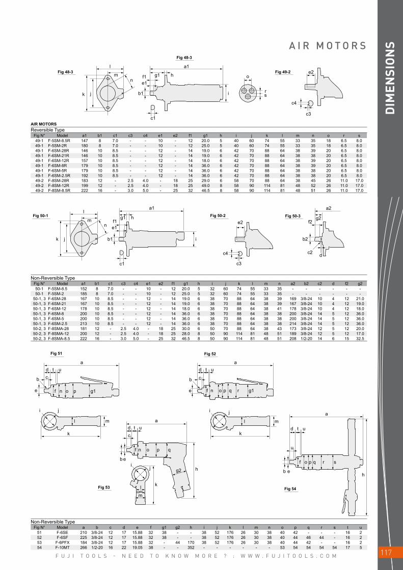
F U J I T O O L S - N E E D T O K N O W M O R E ? : W W W . F U J I T O O L S . C O M 117
l
l
a a
ai j
d
dc
b e
d
d
b
e
cb
e
i j
ct
t
t
t
u
u
u
u
u
b e
mn
b1 i
e1f1
g1 h
a1
e2g2
f2
b2
c2 d
a2
c4
c3c1
k j
mn
a1
c1
b1
e1f1 g1 h o
e2
c4
c3
rsik j
f n o p g1 f n o p q r g1
l
k
m a
f n o p q
h
k
ij
l
m
g2
l m
k
f o p q r s
h
DIM
ENSI
ON
SA I R M O T O R S
AIR MOTORSReversible Type
Fig N° Model a1 b1 c1 c3 c4 e1 e2 f1 g1 h i j k l m n o r s49-1 F-5SM-8.5R 147 8 7.0 - - 10 - 12 20.0 5 40 60 74 55 33 35 18 6.5 8.049-1 F-5SM-2R 180 8 7.0 - - 10 - 12 25.0 5 40 60 74 55 33 35 18 6.5 8.049-1 F-6SM-28R 146 10 8.5 - - 12 - 14 19.0 6 42 70 88 64 38 39 20 6.5 8.049-1 F-6SM-21R 146 10 8.5 - - 12 - 14 19.0 6 42 70 88 64 38 38 20 6.5 8.049-1 F-6SM-12R 157 10 8.5 - - 12 - 14 18.0 6 42 70 88 64 38 39 20 6.5 8.049-1 F-6SM-8R 179 10 8.5 - - 12 - 14 36.0 6 42 70 88 64 38 39 20 6.5 8.049-1 F-6SM-5R 179 10 8.5 - - 12 - 14 36.0 6 42 70 88 64 38 38 20 6.5 8.049-1 F-6SM-2.5R 192 10 8.5 - - 12 - 14 36.0 6 42 70 88 64 38 38 20 6.5 8.049-2 F-8SM-28R 183 12 - 2.5 4.0 - 18 25 29.0 6 58 70 88 64 38 45 26 11.0 17.049-2 F-8SM-12R 199 12 - 2.5 4.0 - 18 25 49.0 8 58 90 114 81 48 52 26 11.0 17.049-2 F-8SM-8.5R 222 16 - 3.0 5.0 - 25 32 46.5 8 58 90 114 81 48 51 26 11.0 17.0
Non-Reversible TypeFig N° Model a1 b1 c1 c3 c4 e1 e2 f1 g1 h i j k l m n a2 b2 c2 d f2 g250-1 F-5SM-8.5 152 8 7.0 - - 10 - 12 20.0 5 32 60 74 55 33 35 - - - - - -50-1 F-5SM-2 185 8 7.0 - - 10 - 12 25.0 5 32 60 74 55 33 35 - - - - - -
50-1, 3 F-6SM-28 167 10 8.5 - - 12 - 14 19.0 6 38 70 88 64 38 39 169 3/8-24 10 4 12 21.050-1, 3 F-6SM-21 167 10 8.5 - - 12 - 14 19.0 6 38 70 88 64 38 39 167 3/8-24 10 4 12 19.050-1, 3 F-6SM-12 178 10 8.5 - - 12 - 14 18.0 6 38 70 88 64 38 41 178 3/8-24 10 4 12 18.050-1, 3 F-6SM-8 200 10 8.5 - - 12 - 14 36.0 6 38 70 88 64 38 38 200 3/8-24 14 5 12 36.050-1, 3 F-6SM-5 200 10 8.5 - - 12 - 14 36.0 6 38 70 88 64 38 38 200 3/8-24 14 5 12 36.050-1, 3 F-6SM-2.5 213 10 8.5 - - 12 - 14 36.0 6 38 70 88 64 38 38 214 3/8-24 14 5 12 36.050-2, 3 F-8SMA-28 181 12 - 2.5 4.0 - 18 25 30.0 6 50 70 88 64 38 43 173 3/8-24 12 5 12 20.050-2, 3 F-8SMA-12 200 12 - 2.5 4.0 - 18 25 28.0 8 50 90 114 81 48 51 189 3/8-24 12 5 12 17.050-2, 3 F-8SMA-8.5 222 16 - 3.0 5.0 - 25 32 46.5 8 50 90 114 81 48 51 208 1/2-20 14 6 15 32.5
Non-Reversible TypeFig N° Model a b c d e f g1 g2 h i j k l m n o p q r s t u
51 F-6SE 210 3/8-24 12 17 15.88 32 38 - - 38 52 176 26 30 38 40 42 - - - 16 252 F-6SF 225 3/8-24 12 17 15.88 32 38 - - 38 52 176 26 30 38 40 44 46 44 - 16 253 F-6PFX 184 3/8-24 12 17 15.88 32 - 44 170 38 52 176 26 30 38 40 44 42 - - 16 254 F-10MT 266 1/2-20 16 22 19.05 38 - - 352 - - - - - - 53 54 54 54 54 17 5
Fig 48-3
Fig 50-1
Fig 51
Fig 53
Fig 52
Fig 54
Fig 50-2 Fig 50-3
Fig 48-3
Fig 49-2

F U J I T O O L S - N E E D T O K N O W M O R E ? : W W W . F U J I T O O L S . C O M118
a
d b
c
f
d g
ab c
w
T
T
H
w
L
L
e
e f
b
e
c
m
h
l
d a
k
i
d
c
g
f
e
a
b
j
DIM
ENSI
ON
S C O M P L E M E N T A R Y R A N G E
Fig N° Model a b c d e f69 FRS-45 421 24 50 46 131 48
ALUMINUM MILLING MACHINESFig N° Model a b c d e
70 FRC-200-1 295 172 111 79 24
ALUMINUM MILLING MACHINESFig N° Model a b c d e f g h i j k l m
71 FRC-300-1 376 252 250 79 140.5 30.5 100 240 222 97 125 50 50.5
AIR FILESFig N° Model a b c d e f g T W L H
68 FRF-4-1F 228 73 133.5 30 40 32 27 4 13 21 6
AIR SAWSFig N° Model a b c d e f g T W L
68 FRF-4-2F 232 77 133.5 30 40 32 27 2 13 21
Fig 69
Fig 68
Fig 70
Fig 71

F U J I T O O L S - N E E D T O K N O W M O R E ? : W W W . F U J I T O O L S . C O M 119
a
e
d
c
b
f DIM
ENSI
ON
SC O M P L E M E N T A R Y R A N G E
PIPE BEVELLING MACHINESFig N° Model a b c d e f
80 FBM-16-1(S) 261 19.0 51 268 48 4280 FBM-24-1(S) 278 27.5 67 240 48 4280 FBM-80A-2(S) 403 39.0 160 388 58 4880 FBM-80A-3(S) 403 39.0 160 388 58 4880 FBM-80A-4(S) 403 39.0 160 388 58 4880 FBM-80A-5(S) 403 39.0 160 388 58 4880 FBM-80A-6(S) 403 39.0 160 388 58 4880 FBM-300-2(S) 524 56.0 179 511 74 9380 FBM-300-3(S) 524 135.0 179 511 74 9380 FBM-300-4(S) 524 135.0 179 511 74 93
SUMP PUMPSFig N° Model a b c d e f
81 FP-7-2 288.6 231.0 9 110 63 PT 3/481 FP-20-1 500.0 374.0 52 200 177 W82.5-581 FP-35-1 607.0 452.6 50 220 187 W82.5-5
PISTON PUMPSFig N° Model a b c d e f g
82 FP-11-1 622 137.5 55 PT 1/4 PT 3/4 PT 11/2 8482 FP-11-2 622 137.5 55 PT 1/4 PT 3/4 PT 11/2 84
Fig 80
Fig 81
Fig 82
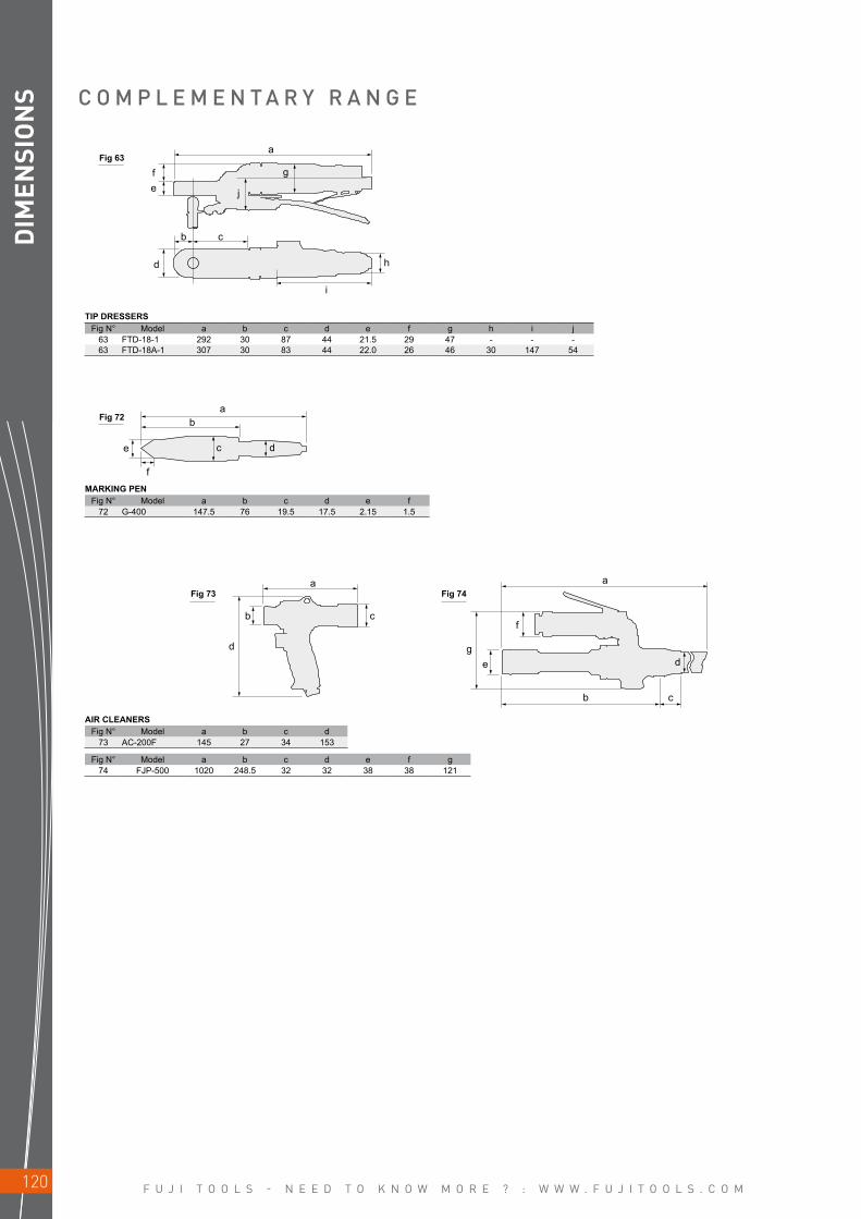
F U J I T O O L S - N E E D T O K N O W M O R E ? : W W W . F U J I T O O L S . C O M120
a
a
a a
g
f
e
b c
d
e
f
b
fe
d
b c
g
h
i
j
c d
d
b c
DIM
ENSI
ON
S C O M P L E M E N T A R Y R A N G E
TIP DRESSERSFig N° Model a b c d e f g h i j
63 FTD-18-1 292 30 87 44 21.5 29 47 - - -63 FTD-18A-1 307 30 83 44 22.0 26 46 30 147 54
Fig N° Model a b c d e f g74 FJP-500 1020 248.5 32 32 38 38 121
MARKING PENFig N° Model a b c d e f
72 G-400 147.5 76 19.5 17.5 2.15 1.5
AIR CLEANERSFig N° Model a b c d
73 AC-200F 145 27 34 153
Fig 63
Fig 72
Fig 73 Fig 74

F U J I T O O L S - N E E D T O K N O W M O R E ? : W W W . F U J I T O O L S . C O M 121
DIM
ENSI
ON
SN O T E S

F U J I T O O L S - N E E D T O K N O W M O R E ? : W W W . F U J I T O O L S . C O M122
V I B R A T I O N A N D N O I S E
VIB
RAT
ION
AN
D N
OIS
E
MODELSOUND PRESS.
SOUND POWER
VIBRATION LEVEL ISO 28927 (m/s2)
ISO 15744 - dB(A) a kAC-200F 87 98 < 2.5 0.5DA-125C-E 81 92 3 1.3DA-125L-E 81 92 3 1.3F-10MT 89 100 < 2.5 0.5F-14CN-1S 102 113 < 2.5 0.5F-14CN-2S 102 113 < 2.5 0.5F-22RCN-1S 102 113 < 2.5 0.5F-22RCR-1S 102 113 < 2.5 0.5F-32RCN-1S 101 112 < 2.5 0.5F-32RCNS-1S 101 112 < 2.5 0.5F-32RCR-1S 101 112 < 2.5 0.5F-5SM-2 89 100 < 2.5 0.5F-5SM-2R 89 100 < 2.5 0.5F-5SM-8.5 89 100 < 2.5 0.5F-5SM-8.5R 89 100 < 2.5 0.5F-6SE 89 100 < 2.5 0.5F-6SF 89 100 < 2.5 0.5F-6SM-12 89 100 < 2.5 0.5F-6SM-12R 89 100 < 2.5 0.5F-6SM-2.5 89 100 < 2.5 0.5F-6SM-2.5R 89 100 < 2.5 0.5F-6SM-21 89 100 < 2.5 0.5F-6SM-21R 89 100 < 2.5 0.5F-6SM-28 89 100 < 2.5 0.5F-6SM-28R 89 100 < 2.5 0.5F-6SM-5 89 100 < 2.5 0.5F-6SM-5R 89 100 < 2.5 0.5F-6SM-8 89 100 < 2.5 0.5F-6SM-8R 89 100 < 2.5 0.5F-8SM-12R 91 102 < 2.5 0.5F-8SM-28R 91 102 < 2.5 0.5F-8SM-8.5R 91 102 < 2.5 0.5F-8SMA-12 91 102 < 2.5 0.5F-8SMA-28 91 102 < 2.5 0.5F-8SMA-8.5 91 102 < 2.5 0.5FA-150K-20 86 97 3,1 1.0FA-150KG-5 89 100 3,1 1.0FA-150KG-7 89 100 3,1 1.0FA-2C-1 89 100 4,3 1.3FA-2C-1BF 89 100 4,3 1.3FA-2C-2 89 100 3,6 2.2FA-2C-2BF 89 100 3,6 2.2FA-2C-30 89 100 3,6 2.2FA-2C-30F 89 100 3,6 2.2FA-2CX-1 89 100 3,6 2.2FA-2CX-1BF 89 100 3,2 1.3FA-2CX-2 89 100 3,6 2.2FA-2CX-2BF 89 100 3,2 1.3FA-2CX-30 89 100 3,6 2.2FA-2CX-30F 89 100 3,2 1.3FA-3C-1 89 100 3,2 1.3FA-3C-1F 89 100 3,2 1.3FA-3C-2 83 94 3,2 1.3FA-3C-2F 85 96 3,2 1.3FA-3CK-1 86 97 3,2 1.3FA-3CK-2 88 99 2,8 1.0FA-3CX-1 88 99 3,2 1.3FA-3CX-1F 78 89 3,2 1.3FA-3CX-2 78 89 3,2 1.3FA-3CX-2F 78 89 3,2 1.3FA-40-1 78 89 4,5 1.4FA-40-1F 75 86 4,5 1.4FA-4C-1 84 95 4,5 1.4FA-4C-1F 84 95 4,5 1.4FA-4C-3 81 92 4,5 1.4FA-4chk-3F 81 92 2,8 1.0FA-5C-1 81 92 5,1 1.6FA-5C-4 81 92 5,1 1.6FA-5C-5 81 92 < 2.5 0.9FA-5E-11V 80 91 5,1 1.6FA-5E-13F 80 91 5,1 1.6FA-5E-13VF 80 91 5,1 1.6FA-5E-1V 87 98 5,1 1.6FA-5E-2F 85 96 5,1 1.6FA-5E-2VF 88 99 4,8 1.5FA-5E-3V 88 99 4,3 1.3FA-5E-6VF 74 85 < 2.5 0.9FA-5E-7V 75 86 2,8 1.0FA-6C-1 88 99 4,7 1.4FA-6C-12 81 92 6,4 1.9FA-6C-12M 81 92 6,4 1.9FA-6C-6M 85 96 6,4 1.9FA-6C-7 85 96 4,7 1.4FA-6C-8M 85 96 4,7 1.4FA-6C-9M 85 96 2,8 1.4FA-7C-1 84 95 3,1 1.0FA-7E-1V 89 100 3,9 1.2FA-7E-2V 89 100 4,6 1.6FA-7E-3V 92 103 6,7 2.3FA-7E-4V 92 103 6,7 2.3FA-7E-5V 89 100 3,9 1.2FA-7E-5VF 89 100 2,8 1.2FA-7E-6VF 89 100 6,7 2.3FA-7E-8VF 89 100 6,7 2.3FA-9C-1 82 93 6,4 2.7FA-9C-2M 79 90 6,4 2.7FA-9C-4M 79 90 6,4 2.7FBM-16-1 83 94 < 2.5 0.3
MODELSOUND PRESS.
SOUND POWER
VIBRATION LEVEL ISO 28927 (m/s2)
ISO 15744 - dB(A) a kFBM-2-1 96 107 < 2.5 0.3FBM-2-1F 96 107 < 2.5 0.3FBM-24-1 83 94 < 2.5 0.1FBM-300-2 89 90 < 2.5 0.2FBM-300-3 89 90 < 2.5 0.2FBM-300-4 89 90 < 2.5 0.2FBM-80A-2 87 98 < 2.5 0.3FBM-80A-3 87 98 < 2.5 0.3FBM-80A-4 87 98 < 2.5 0.3FBM-80A-5 87 98 < 2.5 0.3FBM-80A-6 87 98 < 2.5 0.3FBS-1-1 83 94 < 2.5 0.5FBS-1-2 83 94 < 2.5 0.5FBS-1-3 83 94 < 2.5 0.5FBS-1-4 83 94 < 2.5 0.5FC-01-3 95 106 8,1 2.4FC-01-4 95 106 8,1 2.4FC-01SA-H 93 104 8,3 2.5FC-01SA-R 93 104 8,3 2.5FC-1Z-1 98 109 7,3 2.3FC-1Z-2 98 109 7,3 2.3FC-2Z-1 99 110 7,8 2.4FC-2Z-2 99 110 7,8 2.4FC-3Z-1 100 111 8,4 2.5FC-3Z-2 100 111 8,4 2.5FC-4Z-1 101 112 9 2.7FC-4Z-2 101 112 9 2.7FCD-100R-11S 108 119 < 2.5 0.6FCD-10X-1 84 95 < 2.5 0.4FCD-23R-11S 106 117 < 2.5 0.5FCD-23R-12S 106 117 < 2.5 0.5FCD-32R-11S 104 115 < 2.5 1.4FCD-50R-11S 107 118 < 2.5 0.6FCD-6A-1 80 91 10,4 3.1FCD-6B-1 80 91 10,4 3.1FCD-6B-1F 80 91 10,4 3.1FCD-6EX-3 85 96 9,9 3.0FCD-6EX-4 85 96 9,9 3.0FCD-6X-1 81 92 < 2.5 0.5FCD-6X-2 81 92 < 2.5 0.6FCD-75R-11S 105 116 < 2.5 0.6FCH-20 94 105 7,7 2.3FCH-20-1F 94 105 7,7 2.3FCH-20F 97 108 8,4 2.5FCH-20F-1F 94 105 8,4 2.5FCH-25 96 107 12,3 3.7FCH-25-1F 96 107 12,3 3.7FCH-25B 97 108 11,9 3.6FCH-25B-1F 97 108 11,9 3.6FD-4 77 88 2,7 0.8FD-4P 77 88 2,7 0.8FD-5 78 89 4 1.3FD-5P 78 89 4 1.3FET-11-1 85 96 < 2.5 0.7FET-13-1 83 94 4,9 2.4FET-16-1 85 96 4,9 2.4FET-4-1 75 86 < 2.5 0.4FET-5-1 79 90 < 2.5 0.8FET-6-1 79 90 < 2.5 0.8FET-7-1 81 92 < 2.5 0.9FET-9-1 80 91 3,7 1.5FG-06-1 71 82 < 2.5 0.8FG-06-S-1 76 87 < 2.5 0.7FG-12U-1 85 96 < 2.5 0.4FG-12U-1F 85 96 < 2.5 0.4FG-12U-2 85 96 < 2.5 0.4FG-12UX-1 85 96 < 2.5 0.4FG-12UX-1F 85 96 < 2.5 0.4FG-12UX-2 85 96 < 2.5 0.4FG-13-1 85 96 < 2.5 0.4FG-13-10 85 96 < 2.5 0.5FG-13-10F 85 96 < 2.5 0.5FG-13-1F 85 96 < 2.5 0.4FG-13-2 85 96 < 2.5 0.4FG-13-20 85 96 < 2.5 0.5FG-13X-1 79 90 < 2.5 0.5FG-13X-10 79 90 < 2.5 0.5FG-13X-10F 79 90 < 2.5 0.5FG-13X-1F 79 90 < 2.5 0.5FG-13X-2 85 96 < 2.5 0.5FG-13X-20 85 96 < 2.5 0.5FG-25D-1 80 91 < 2.5 0.4FG-25D-1F 80 91 < 2.5 0.4FG-25D-2 80 91 < 2.5 0.7FG-25DX-1 84 95 < 2.5 0.4FG-25DX-1F 84 95 < 2.5 0.4FG-25DX-2 84 95 < 2.5 0.4FG-25T 82 93 4,2 1.5FG-26H-1 78 89 1,8 0.6FG-26H-1F 78 89 1,8 0.6FG-26HL-1F 79 90 < 2.5 1.3FG-26HL-2 79 90 < 2.5 1.3FG-26HL-2N 79 90 < 2.5 1.3FG-26H-2 78 89 1,8 0.6FG-26HX-1 79 90 < 2.5 1.0FG-26HX-1F 79 90 < 2.5 1.0FG-26HX-2 78 89 < 2.5 1.0FG-26L-1 85 96 3 1.0
Listed specifications are for reference only. Please check documents in each tool.

F U J I T O O L S - N E E D T O K N O W M O R E ? : W W W . F U J I T O O L S . C O M 123
V I B R A T I O N A N D N O I S E
VIB
RAT
ION
AN
D N
OIS
E
MODELSOUND PRESS.
SOUND POWER
VIBRATION LEVEL ISO 28927 (m/s2)
ISO 15744 - dB(A) a kFG-26L-1BF 85 96 3 1.0FG-26L-1N 85 96 3 1.0FG-2VX-1F 81 92 3,6 1.2FG-3H-1 85 96 2,7 0.9FG-3H-1F 81 92 2,9 0.9FG-3H-2 81 92 2,9 0.9FG-3H-2F 81 92 2,9 0.9FG-3H-5F 82 93 2,9 0.9FG-3H-6 82 93 2,9 0.9FG-3HA-1 91 102 2,9 0.9FG-3HA-2 92 103 2,9 0.9FG-3HL-1 83 94 3,1 0.9FG-3HL-1A 83 94 3,5 1.1FG-3HL-1F 83 94 3,1 0.9FG-3HY-1 80 91 2,6 0.8FG-3HY-1A 80 91 2,6 0.8FG-3VX-1F 73 84 < 2.5 0.8FG-3VX-2F 73 84 < 2.5 0.8FG-3VX-3F 73 84 < 2.5 0.8FG-3VX-6F 73 84 < 2.5 0.8FG-4H-1 83 94 < 2.5 0.8FG-4H-1F 83 94 3,2 1.7FG-4H-2 83 94 3,2 1.7FG-4H-2F 83 94 3,2 1.7FG-4HL-1 81 92 2,6 0.8FG-4HL-1A 81 92 2,6 0.8FG-4HL-1F 81 92 2,6 0.8FG-4VA-1 90 101 < 2.5 0.6FG-4VA-2 90 101 < 2.5 0.6FG-50-25 87 98 3,6 1.7FG-50D-1 87 98 <2.5 0.4FG-50D-1F 87 98 <2.5 0.4FG-50D-2 87 98 3,6 1.7FG-50DX-1 85 96 <2.5 0.4FG-50DX-1F 85 96 <2.5 0.4FG-50DX-2 85 96 3,6 1.7FG-50H-1 81 92 <2.5 0.4FG-50H-1F 81 92 <2.5 0.4FG-50H-2 79 90 <2.5 0.4FG-50HX-1 81 92 <2.5 0.4FG-50HX-1F 81 92 <2.5 0.4FG-50HX-2 79 90 <2.5 0.4FG-50K-1 87 98 3,6 1.7FG-50L-1 84 95 3,3 1.8FG-50L-1A 84 95 3,3 1.8FG-50L-1BF 84 95 3,3 1.8FG-50Y-1 86 97 3,3 1.8FG-50Y-1A 86 97 3,3 1.8FG-50Y-1BF 86 97 3,3 1.8FG-5H-1 80 91 < 2.5 0.5FG-5H-1M 80 91 < 2.5 0.5FG-5H-2 80 91 < 2.5 0.3FG-5H-2M 80 91 < 2.5 0.3FG-5H-3 76 87 1,1 0.4FG-5HL 83 94 < 2.6 0.3FG-5HL-1 83 94 < 2.6 0.3FG-5HL-11 90 101 4,8 1.5FG-5HL-11A 90 101 4,8 1.5FG-5HL-13 83 94 4,8 1.5FG-5HL-13A 83 94 4,8 1.5FG-5HL-1A 90 101 4,8 1.5FG-5HL-2 83 94 < 2.5 0.3FG-5HL-2A 83 94 < 2.5 0.3FG-5HL-2M 83 94 < 2.5 0.3FG-5PX-1 84 95 < 2.5 0.5FG-6H-1 83 94 < 2.5 1.3FG-6H-1M 83 94 < 2.5 1.3FG-8H-1 87 98 < 2.5 0.4FG-8H-1C 87 98 < 2.5 0.4FG-8H-1M 87 98 < 2.5 0.4FG-8H-2M 88 99 < 2.5 0.3FJP-500 98 109 < 2.5FL-4-1 76 87 < 2.5 0.8FL-4D-1 76 87 < 2.5 0.6FL-4S-1 72 83 < 2.5 0.8FL-4SD-1 72 83 3 1.4FL-5-1 79 90 < 2.5 0.4FL-5D-1 79 90 < 2.5 0.7FL-5S-1 79 90 4,3 2.2FL-5SD-1 79 90 4,6 2.3FL-6-1 82 93 < 2.5 0.6FL-6D-1 82 93 < 2.5 0.7FL-6S-1 80 91 5,2 2.4FL-6SD-1 80 91 4,9 2.3FL-7-1 84 95 < 2.5 0.6FL-9-1 79 90 3,4 1.3FL-11-1 85 96 < 2.5 0.7FL-13-1 84 95 4.1 2.1FLT-11-1 85 96 3,9 1.8FLT-13-1 83 94 4,9 2.4FLT-20S-1 89 100 7,1 3.3FLT-4-1 75 86 < 2.5 0.4FLT-4-1L 72 83 < 2.5 0.4FLT-4D-1(10) 75 86 < 2.5 0.7FLT-4D-1(10)L 77 88 3,7 2.3FLT-4S-1 77 88 3,7 2.3FLT-4S-1L 77 88 3,7 2.3FLT-4SD-1 77 88 < 2.5 1.0
MODELSOUND PRESS.
SOUND POWER
VIBRATION LEVEL ISO 28927 (m/s2)
ISO 15744 - dB(A) a kFLT-4SD-1L 77 88 < 2.5 1.0FLT-5-1 79 90 < 2.5 0.8FLT-5-1L 75 86 < 2.5 0.8FLT-5D-1(10) 79 90 < 2.5 0.7FLT-5D-1(10)L 75 86 < 2.5 0.8FLT-5S-1 80 91 3,4 1.6FLT-5S-1L 79 90 2,8 1.3FLT-5SD-1 80 91 3,7 2.0FLT-5SD-1L 79 90 3 1.4FLT-6-1 79 90 < 2.5 0.8FLT-6-1L 76 87 < 2.5 0.8FLT-6D-1(10) 79 90 < 2.5 0.8FLT-6D-1(10)L 76 87 < 2.5 0.8FLT-6S-1 79 90 6,2 2.1FLT-6S-1L 79 90 6,2 2.1FLT-6SD-1 79 90 4,6 2.2FLT-7-1 81 92 < 2.5 0.9FLT-7-1L 81 92 < 2.5 0.9FLT-9-1 80 91 3,7 1.5FLT-9-1L 80 91 3,7 1.5FLT-11-1 85 96 3,9 1.8FLT-11-1L 83 94 3,9 1.8FLT-13-1 83 94 4,9 2.4FLT-13-1L 81 92 4,9 2.4FNS-2 99 110 8 2.5FNS-2-1F 99 110 8 2.5FNS-2P 99 110 7,4 2.3FNS-2P-1F 99 110 7,4 2.3FOR-125B-E 81 92 3 1.3FOR-125BF-E 81 92 3 1.3FOR-150B-E 81 92 3 1.3FOR-150BF-E 81 92 3 1.3FOS-175B-E 81 92 3 1.3FOS-175BF-E 81 92 3 1.3FOS-230B-E 81 92 3 1.3FOS-230BF-E 81 92 3 1.3FP-11-1 78 89 3 1.4FP-11-2 78 89 3 1.4FP-20-1 78 89 3 1.4FP-35-1 78 89 3 1.4FP-7-2 78 89 3 1.4FPT-110-1 72 83 < 2.5 0.5FPT-110D-1 72 83 < 2.5 0.5FPT-110S-1 72 83 < 2.5 0.5FPT-110SD-1 72 83 3,5 1.1FPT-1660-1 89 100 7,1 3.3FPT-330S-1 74 85 3,2 1.0FPT-330SD-1 74 85 3,2 1.0FPT-440SC-1 82 93 3,2 1.0FPT-550SC-1 82 93 3,4 1.6FPT-660SC-1 82 93 4,6 2.2FPT-770SC-1 82 93 4,6 2.2FPT-770SCG-1 82 93 4,6 2.2FPW-110-1 72 83 < 2.5 0.5FPW-110D-1 72 83 < 2.5 0.5FPW-110D-10 72 83 < 2.5 0.5FPW-110S-1 72 83 2,8 0.9FPW-110SD-1 72 83 3 0.9FPW-1660-1 89 100 7,1 3.3FPW-2220S-1 91 102 6,3 3.1FPW-330S-1 74 85 3,2 1.0FPW-330SD-1 74 85 3,2 1.0FPW-440SC-1 82 93 3,2 1.0FPW-550SC-1 82 93 3,4 1.6FPW-660SC-1 82 93 4,6 2.2FPW-770S-1 82 93 4,6 2.2FPW-770SC-1 82 93 4,6 2.2FPW-770SCG-1 82 93 4,6 2.2FR-18B 95 106 19,4 5.9FR-18B-2F 95 106 19,4 5.9FR-18L 95 106 19,4 5.9FR-18L-2F 95 106 19,4 5.9FR-22B 94 105 19,4 6.1FR-22B-2F 94 105 19,4 6.1FR-22L 94 105 19,4 6.1FR-22L-2F 94 105 19,4 6.1FR-25B 94 105 22,3 7.4FR-25B-2F 94 105 22,3 7.4FR-25L 94 105 22,3 7.4FR-25L-2F 94 105 22,3 7.4FR-32 96 107 25,8 7.8FR-32-2F 96 107 25,8 7.8FRC-200-1 104 115 < 2.5 0.6FRC-300-1 107 118 2,5 0.8FRD-100R-1 110 121 2,5 0.8FRD-12Z-1 89 100 < 2.5 0.5FRD-12Z-1C 89 100 < 2.5 0.5FRD-16Z-1 90 101 < 2.5 0.5FRD-16Z-1C 90 101 < 2.5 0.5FRD-20R-21 98 109 3,8 1.2FRD-20R-22 98 109 3,8 1.2FRD-23R-21 98 109 3,8 1.2FRD-23R-22 98 109 3,8 1.2FRD-25R-11 98 109 3,8 1.2FRD-28R-11 98 109 3,8 1.2FRD-32R-11 110 121 2,5 0.8FRD-32R-12 110 121 2,5 0.8FRD-40R-11 110 121 2,5 0.8

F U J I T O O L S - N E E D T O K N O W M O R E ? : W W W . F U J I T O O L S . C O M124
V I B R A T I O N A N D N O I S E
VIB
RAT
ION
AN
D N
OIS
E
MODELSOUND PRESS.
SOUND POWER
VIBRATION LEVEL ISO 28927 (m/s2)
ISO 15744 - dB(A) a kFRD-50R-11 110 121 2,5 0.8FRD-5P-1 75 86 < 2.5 0.5FRD-5S-1 85 96 < 2.5 0.7FRD-5S-1F 85 96 < 2.5 0.7FRD-5S-2T 85 96 3 0.9FRD-5S-2TF 85 96 3 0.9FRD-65R-1 110 121 2,5 0.8FRD-6PH-2 73 84 < 2.5 1.0FRD-6PH-3 73 84 < 2.5 1.0FRD-6PH-5 71 82 < 2.5 1.1FRD-6PH-7 73 84 < 2.5 0.7FRD-6PX-1T 71 82 < 2.5 1.1FRD-6S-1T 71 82 < 2.5 1.1FRD-6S-2 71 82 < 2.5 1.1FRD-6S-2F 71 82 < 2.5 1.1FRD-6S-3 92 103 2,7 0.8FRD-6S-3F 92 103 2,7 0.8FRD-6S-5 86 97 2,9 0.9FRD-6S-5F 86 97 2,9 0.9FRD-6S-7 91 102 4,3 1.3FRD-6S-7F 91 102 4,3 1.3FRD-75R-1 110 121 2,5 0.8FRD-8PX-1 82 92 < 2.5 0.5FRD-8PX-2 82 92 < 2.5 0.6FRD-8PX-3 82 92 < 2.5 0.6FRF-4-1F 80 91 8,1 2.5FRF-4-2F 80 91 8,1 2.5FRH-3-1 91 102 8,1 2.5FRH-3-2 91 102 6,3 1.9FRH-6-1 91 102 5,6 1.7FRH-6-2 91 102 5,6 1.7FRH-6A-1 101 112 11,8 3.5FRH-6A-2 101 112 11,8 3.5FRS-45 82 92 10,4 3.1FRW-10N-2 90 101 < 2.5 0.7FRW-13N-3 92 103 < 2.5 0.6FRW-13N-4 92 103 < 2.5 0.7FRW-6NX-3 85 96 < 2.5 0.6FRW-6NX-3A 85 96 < 2.5 0.6FRW-6NX-4 89 100 3,5 1.2FRW-6NX-4A 89 100 3,5 1.2FRW-8NX-2 90 101 < 2.5 0.6FRW-8NX-2A 90 101 < 2.5 0.6FS-2A 88 99 4,9 6.9FS-2A-1F 88 99 4,9 6.9FT-13Z-1 89 100 < 2.5 0.5FT-6BX-1 71 82 < 2.5 0.4FT-6P-1 71 82 < 2.5 0.6FT-8PX-1 82 92 < 2.5 0.4FTD-18-1 84 95 3,1 1.0FTD-18A-1 86 97 3,1 1.0FV-7-1M 79 90 6,3 2.1FV-7-2M 89 100 2,9 0.9FV-7-4M 89 100 4,9 1.5FV-9BH-1M 93 104 3 0.9FV-9BH-4M 93 104 < 2.5 0.6FW-100-1 107 118 4,5 1.5FW-10PH-1 93 104 5 1.6FW-10PH-2 96 107 5,7 1.7FW-10SX-5 88 99 4,2 1.3FW-14PH-1 92 103 4,2 1.3FW-14PH-2 92 103 4,2 1.3FW-14PH-3 95 106 4,2 1.3FW-14PX-5 90 101 3,1 1.0FW-14SX-5 90 101 3,1 1.0FW-19PX-5 93 104 9,2 2.8FW-19Z-5 93 104 9,2 2.8FW-19Z-5C 93 104 9,2 2.8FW-250-1 94 105 8,8 3.7FW-250-1C 94 105 8,8 3.7FW-250-2 94 105 6,9 2.1FW-250-2C 94 105 6,9 2.1FW-250P-1 98 109 9,2 3.0FW-250P-2 98 109 10,3 3.2FW-320-1 93 104 13,3 4.3FW-320-1C 93 104 13,3 4.3FW-320-1CL 93 104 13,3 4.3FW-320-1L 93 104 13,3 4.3FW-320P-1 100 111 20,05 6.2FW-420-1 98 109 13,7 4.4FW-420-1C 98 109 13,7 4.4FW-420-1CL 98 109 13,7 4.4FW-420-1L 98 109 13,7 4.4FW-420-2 98 109 13,7 4.4FW-420-2C 98 109 13,7 4.4FW-44PA-2 77 88 5,2 1.6FW-44PAD-2 77 88 5,2 1.6FW-44PAD-20 77 88 5,2 1.6FW-44SA-1 86 97 5,5 1.7FW-44SAD-1 86 97 5,2 1.7FW-44SAD-10 86 97 5,2 1.7
MODELSOUND PRESS.
SOUND POWER
VIBRATION LEVEL ISO 28927 (m/s2)
ISO 15744 - dB(A) a kFW-50-7 104 115 4,7 1.7FW-5PX-6 89 100 3,1 1.2FW-5PXD-6 89 100 4 1.2FW-5PXD-60 89 100 4 1.2FW-5SXD-7 82 93 9,5 2.8FW-5SXD-70 82 93 9,5 2.8FW-5SXD-8 81 92 9,4 2.8FW-5SXD-80 81 92 9,4 2.8FW-66PA-2 78 89 6,5 1.9FW-66PAD-2 78 89 4,5 1.4FW-66PAD-20 78 89 4,5 1.4FW-66SA-1 83 94 7,6 2.3FW-66SAD-1 83 94 6,6 2.0FW-66SAD-10 83 94 6,6 2.0FW-6PH-1 95 106 4,5 1.4FW-6PH-11 95 106 9 2.7FW-6PHD-1 95 106 5,3 1.7FW-6PL-1 91 102 4,8 1.5FW-6PLD-1 91 102 4,7 1.4FW-6PM-1 94 105 4,6 1.6FW-6PMD-1 94 105 4,6 1.5FW-6PMD-10 94 105 4,6 1.5FW-6PX-5 94 105 4,2 1.3FW-6PX-6 94 105 3,7 1.2FW-6PXD-6 94 105 4,1 1.4FW-6PXD-60 94 105 4,1 1.4FW-6SCX-6 93 104 8,9 2.8FW-6SX-5 95 106 5 1.5FW-6SX-6 95 106 5,3 1.6FW-6SXD-6 92 103 7,2 2.2FW-6SXD-60 92 103 7,2 2.2FW-75-7 107 118 4,5 1.5FW-88P-1 94 105 4,5 1.4FW-8PH-3 94 105 5,1 1.6FW-8SCH-2 92 103 7,4 2.3FW-8SH-2 95 106 6,3 1.9G-400 79 90 5,1 2.4OB-75L-E(M) 81 92 3 1.3OB-90L-E(M) 81 92 3 1.3TURBO-100 85 96 < 2.5 2.0TURBO-100A 84 95 < 2.5 1.7
Fuji Tools follows a policy of continuous product improvement. Specifications and descriptions are thus subject to change without notice.Please contact your Fuji representative for the latest product information.

F U J I T O O L S - N E E D T O K N O W M O R E ? : W W W . F U J I T O O L S . C O M 125
VIB
RAT
ION
AN
D N
OIS
EN O T E S

F U J I T O O L S - N E E D T O K N O W M O R E ? : W W W . F U J I T O O L S . C O M126
I N D E XMODELS RANGE PAGEAC-200F Specialty Tools 100DA-125C-E(M) Orbital Sanders 61DA-125L-E(M) Orbital Sanders 61F-10MT Air Motors 90F-14CN-1S Corner Drills 75F-14CN-2S Corner Drills 75F-22RCN-1S Corner Drills 75F-22RCR-1S Corner Drills 75F-32RCN-1S Corner Drills 75F-32RCNS-1S Corner Drills 75F-32RCR-1S Corner Drills 75F-5SM-2 Air Motors 91F-5SM-2R Air Motors 90F-5SM-8.5 Air Motors 91F-5SM-8.5R Air Motors 90F-6SE Air Motors 90F-6SF Air Motors 90F-6SM-12 Air Motors 91F-6SM-12R Air Motors 90F-6SM-2.5 Air Motors 91F-6SM-2.5R Air Motors 90F-6SM-21 Air Motors 91F-6SM-21R Air Motors 90F-6SM-28 Air Motors 91F-6SM-28R Air Motors 90F-6SM-5 Air Motors 91F-6SM-5R Air Motors 90F-6SM-8 Air Motors 91F-6SM-8R Air Motors 90F-8SM-12R Air Motors 90F-8SM-28R Air Motors 90F-8SM-8.5R Air Motors 90F-8SMA-12 Air Motors 91F-8SMA-28 Air Motors 91F-8SMA-8.5 Air Motors 91FA-150K-20 Angle Sanders 57FA-150KG-5 Angle Grinders 57FA-150KG-7 Angle Sanders 57FA-2C-1 Angle Grinders 55FA-2C-2 Angle Grinders 55FA-2C-30 Angle Grinders 55FA-2CX-1 Angle Grinders 55FA-2CX-2 Angle Grinders 55FA-2CX-30 Angle Grinders 55FA-3C-1 Angle Grinders 55FA-3C-2 Angle Grinders 55FA-3CK-1 Angle Sanders 57FA-3CK-2 Angle Grinders 57FA-3CX-1 Angle Grinders 55FA-3CX-2 Angle Grinders 55FA-40-1 Angle Grinders 56FA-40-1F Angle Grinders 56FA-4C-1 Angle Grinders 56FA-4C-1F Angle Grinders 56FA-4C-3 Angle Grinders 56FA-4chk-3F Angle Sanders 58FA-5C-1 Angle Grinders 56FA-5C-4 Angle Grinders 56FA-5C-5 Angle Sanders 57FA-5E-11V Angle Grinders 56FA-5E-13F Angle Grinders 56FA-5E-13VF Angle Grinders 56FA-5E-1V Angle Grinders 56FA-5E-2F Angle Grinders 56FA-5E-2VF Angle Grinders 56FA-5E-3V Angle Grinders 56FA-5E-6VF Angle Sanders 58FA-5E-7V Angle Sanders 57FA-6C-1 Angle Grinders 56FA-6C-12 Angle Grinders 56FA-6C-12M Angle Grinders 56FA-6C-6M Angle Grinders 56FA-6C-7 Angle Grinders 56FA-6C-8M Angle Grinders 56FA-6C-9M Angle Grinders 56FA-6C-9M Angle Sanders 58FA-7C-1 Angle Grinders 56FA-7E-1V Angle Grinders 56FA-7E-2V Angle Grinders 56FA-7E-3V Angle Grinders 56FA-7E-4V Angle Grinders 56FA-7E-5V Angle Grinders 56FA-7E-5VF Angle Grinders 56FA-7E-5VF Angle Sanders 58FA-7E-6VF Angle Grinders 56FA-7E-8VF Angle Grinders 56FA-9C-1 Angle Grinders 56FA-9C-2 Angle Grinders 56FA-9C-2M Angle Grinders 56FA-9C-4 Angle Grinders 56FA-9C-4M Angle Grinders 56FA-9C-6 Angle Grinders 56FBM-16-1(S) Specialty Tools 96FBM-2-1 Specialty Tools 95FBM-2-1F Specialty Tools 95FBM-24-1 (S) Specialty Tools 96FBM-300-2(S) Specialty Tools 96FBM-300-3(S) Specialty Tools 96FBM-300-4(S) Specialty Tools 96FBM-80A-2(S) Specialty Tools 96
MODELS RANGE PAGEFBM-80A-3(S) Specialty Tools 96FBM-80A-4(S) Specialty Tools 96FBM-80A-5(S) Specialty Tools 96FBM-80A-6(S) Specialty Tools 96FBS-1-1 Belt Sanders 60FBS-1-2 Belt Sanders 60FBS-1-3 Belt Sanders 60FBS-1-4 Belt Sanders 60FC-01-3 Percussive Tools 83FC-01-4 Percussive Tools 83FC-01SA-H Percussive Tools 83FC-01SA-R Percussive Tools 83FC-1Z-1 Percussive Tools 83FC-1Z-2 Percussive Tools 83FC-2Z-1 Percussive Tools 83FC-2Z-2 Percussive Tools 83FC-3Z-1 Percussive Tools 83FC-3Z-2 Percussive Tools 83FC-4Z-1 Percussive Tools 83FC-4Z-2 Percussive Tools 83FCD-100R-11S Corner Drills 75FCD-10X-1 Drills 74FCD-10X-1F Drills 74FCD-23R-11S Corner Drills 75FCD-23R-12S Corner Drills 75FCD-32R-11S Corner Drills 75FCD-50R-11S Corner Drills 75FCD-6A-1 Drills 74FCD-6B-1 Drills 74FCD-6B-1F Drills 74FCD-6EX-3 Drills 74FCD-6EX-4 Drills 74FCD-6X-1 Drills 74FCD-6X-1F Drills 74FCD-6X-2 Drills 74FCD-6X-2F Drills 74FCD-75R-11S Corner Drills 75FCH-20 Percussive Tools 82FCH-20-1F Percussive Tools 82FCH-20F Percussive Tools 82FCH-20F-1F Percussive Tools 82FCH-25 Percussive Tools 82FCH-25-1F Percussive Tools 82FCH-25B Percussive Tools 82FCH-25B-1F Percussive Tools 82FD-4 Screwdrivers 36FD-4P Screwdrivers 36FD-5 Screwdrivers 36FD-5P Screwdrivers 36FET-11-1 Pulse Wrenches 19FET-13-1 Pulse Wrenches 19FET-16-1 Pulse Wrenches 19FET-4-1 Pulse Wrenches 19FET-4D-1 Pulse Wrenches 19FET-5-1 Pulse Wrenches 19FET-5D-1 Pulse Wrenches 19FET-6-1 Pulse Wrenches 19FET-6D-1 Pulse Wrenches 19FET-7-1 Pulse Wrenches 19FET-9-1 Pulse Wrenches 19FG-06-1 Pencil Grinder 46FG-06-S-1 Pencil Grinder 46FG-12U-1 Die Grinders 48FG-12U-1F Die Grinders 48FG-12U-2 Die Grinders 48FG-12UX-1 Die Grinders 48FG-12UX-1F Die Grinders 48FG-12UX-2 Die Grinders 48FG-13-1 Die Grinders 47FG-13-10 Die Grinders 47FG-13-10F Die Grinders 47FG-13-1F Die Grinders 47FG-13-2 Die Grinders 47FG-13-20 Die Grinders 47FG-13X-1 Die Grinders 47FG-13X-10 Die Grinders 47FG-13X-10F Die Grinders 47FG-13X-1F Die Grinders 47FG-13X-2 Die Grinders 47FG-13X-20 Die Grinders 47FG-25D-1 Die Grinders 48FG-25D-1F Die Grinders 48FG-25D-2 Die Grinders 48FG-25DX-1 Die Grinders 48FG-25DX-1F Die Grinders 48FG-25DX-2 Die Grinders 48FG-25T Die Grinders 49FG-26H-1 Die Grinders 49FG-26H-1F Die Grinders 49FG-26H-2 Die Grinders 49FG-26HX-1 Die Grinders 49FG-26HX-1F Die Grinders 49FG-26HX-2 Die Grinders 49FG-26HL-2 Straight Grinders 52FG-26HL-2N Straight Grinders 52FG-26HL-1F Straight Grinders 52FG-26L-1 Straight Grinders 52FG-26L-1BF Straight Grinders 52FG-26L-1N Straight Grinders 52FG-2VX-1F Grinder 50
MODELS RANGE PAGEFG-3H-1 Grinder 51FG-3H-1F Straight Grinders 51FG-3H-2 Straight Grinders 51FG-3H-2F Straight Grinders 51FG-3H-5F Straight Grinders 52FG-3H-6 Grinder 50FG-3HA-1 Straight Grinders 52FG-3HA-2 Straight Grinders 52FG-3HL-1 Extended Grinders 53FG-3HL-1A Extended Grinders 54FG-3HL-1F Extended Grinders 53FG-3HY-1 Extended Grinders 53FG-3HY-1A Extended Grinders 54FG-3VX-1F Grinder 50FG-3VX-2F Grinder 50FG-3VX-3F Grinder 50FG-3VX-6F Grinder 50FG-4H-1 Straight Grinders 51FG-4H-1F Straight Grinders 51FG-4H-2 Straight Grinders 51FG-4H-2F Straight Grinders 51FG-4HL-1 Extended Grinders 53FG-4HL-1A Extended Grinders 54FG-4HL-1F Extended Grinders 53FG-4VA-1 Grinder 50FG-4VA-2 Grinder 50FG-50-25 Die Grinders 49FG-50D-1 Die Grinders 48FG-50D-1F Die Grinders 48FG-50D-2 Die Grinders 48FG-50DX-1 Die Grinders 48FG-50DX-1F Die Grinders 48FG-50DX-2 Die Grinders 48FG-50H-1 Die Grinders 49FG-50H-1F Die Grinders 49FG-50H-2 Die Grinders 49FG-50HX-1 Die Grinders 49FG-50HX-1F Die Grinders 49FG-50HX-2 Die Grinders 49FG-50K-1 Die Grinders 48FG-50L-1 Extended Grinders 53FG-50L-1A Extended Grinders 54FG-50L-1BF Extended Grinders 53FG-50Y-1 Extended Grinders 53FG-50Y-1A Extended Grinders 54FG-50Y-1BF Extended Grinders 53FG-5H-1 Straight Grinders 51FG-5H-1M Straight Grinders 51FG-5H-2 Straight Grinders 51FG-5H-2M Straight Grinders 51FG-5H-3 Straight Grinders 51FG-5HL Extended Grinders 54FG-5HL-1 Extended Grinders 53FG-5HL-11 Extended Grinders 53FG-5HL-11A Extended Grinders 54FG-5HL-1A Extended Grinders 54FG-5HL-2 Extended Grinders 53FG-5HL-2A Extended Grinders 54FG-5HL-2M Extended Grinders 53FG-5PX-1 Disc Sanders 58FG-6H-1 Straight Grinders 51FG-6H-1M Straight Grinders 51FG-8H-1 Straight Grinders 51FG-8H-1C Straight Grinders 51FG-8H-1M Straight Grinders 51FG-8H-2M Straight Grinders 51FJP-500 Specialty Tools 100FJT-10-1 Testers 16FJT-10A-1 Testers 16FJT-10B-1 Testers 16FJT-10C-1 Testers 16FJT-16-1 Testers 16FJT-16A-1 Testers 16FJT-16B-1 Testers 16FJT-16C-1 Testers 16FJT-5-1 Testers 16FJT-5A-1 Testers 16FJT-5B-1 Testers 16FJT-5C-1 Testers 16FL-11-1 Pulse Wrenches 23FL-13-1 Pulse Wrenches 23FL-4-1 Pulse Wrenches 23FL-4D-1(10) Pulse Wrenches 23FL-4S-1 Pulse Wrenches 23FL-4SD-1(10) Pulse Wrenches 23FL-5-1 Pulse Wrenches 23FL-5D-1(10) Pulse Wrenches 23FL-5S-1 Pulse Wrenches 23FL-5SD-1(10) Pulse Wrenches 23FL-6-1 Pulse Wrenches 23FL-6D-1(10) Pulse Wrenches 23FL-6S-1 Pulse Wrenches 23FL-6SD-1(10) Pulse Wrenches 23FL-7-1 Pulse Wrenches 23FL-9-1 Pulse Wrenches 23FLT-11-1 Pulse Wrenches 27FLT-13-1 Pulse Wrenches 27FLT-20S-1 Pulse Wrenches 27FLT-4-1 Pulse Wrenches 27FLT-4D-1(10) Pulse Wrenches 27
IND
EX

F U J I T O O L S - N E E D T O K N O W M O R E ? : W W W . F U J I T O O L S . C O M 127
I N D E XMODELS RANGE PAGEFLT-4D-1(10)L Pulse Wrenches 27FLT-4-1L Pulse Wrenches 27FLT-4S-1 Pulse Wrenches 27FLT-4S-1L Pulse Wrenches 27FLT-4SD-1(10) Pulse Wrenches 28FLT-4SD-1(10)L Pulse Wrenches 28FLT-5-1 Pulse Wrenches 27FLT-5-1L Pulse Wrenches 27FLT-5D-1(10) Pulse Wrenches 27FLT-5D-1(10)L Pulse Wrenches 27FLT-5S-1 Pulse Wrenches 27FLT-5S-1L Pulse Wrenches 27FLT-5SD-1(10) Pulse Wrenches 28FLT-5SD-1(10)L Pulse Wrenches 28FLT-6-1 Pulse Wrenches 27FLT-6-1L Pulse Wrenches 27FLT-6D-1(10) Pulse Wrenches 27FLT-6D-1(10)L Pulse Wrenches 27FLT-6S-1 Pulse Wrenches 27FLT-6S-1L Pulse Wrenches 27FLT-6SD-1(10) Pulse Wrenches 28FLT-6SD-1(10)L Pulse Wrenches 28FLT-7-1 Pulse Wrenches 27FLT-7-1L Pulse Wrenches 27FLT-9-1 Pulse Wrenches 27FLT-9-1L Pulse Wrenches 27FLT-11-1 Pulse Wrenches 27FLT-11-1L Pulse Wrenches 27FLT-13-1 Pulse Wrenches 27FLT-13-1L Pulse Wrenches 27FNS-2 Percussive Tools 83FNS-2 Percussive Tools 83FNS-2-1F Percussive Tools 83FNS-2P Percussive Tools 83FNS-2P Percussive Tools 83FNS-2P-1F Percussive Tools 83FOR-125B-E(M) Orbital Sanders 61FOR-125BF-E(M) Orbital Sanders 61FOR-150B-E(M) Orbital Sanders 61FOR-150BF-E(M) Orbital Sanders 61FOS-175B-E(M) Rectangle Sheet Sander 61FOS-175BF-E(M) Rectangle Sheet Sander 61FOS-230B-E Rectangle Sheet Sander 61FOS-230BF-E Rectangle Sheet Sander 61FP-11-1 Specialty Tools 98FP-11-2 Specialty Tools 98FP-20-1 Specialty Tools 98FP-35-1 Specialty Tools 98FP-7-2 Specialty Tools 98FPT-110-1 Pulse Wrenches 28FPT-110D-1(10) Pulse Wrenches 28FPT-110S-1 Pulse Wrenches 28FPT-110SD-1(10) Pulse Wrenches 29FPT-1660-1 Pulse Wrenches 28FPT-330S-1 Pulse Wrenches 28FPT-330SD-1(10) Pulse Wrenches 29FPT-440SC-1 Pulse Wrenches 29FPT-550SC-1 Pulse Wrenches 29FPT-660SC-1 Pulse Wrenches 29FPT-770S-1 Pulse Wrenches 28FPT-770SC-1 Pulse Wrenches 29FPT-770SCG-1 Pulse Wrenches 29FPW-110-1 Pulse Wrenches 24FPW-110D-1 Pulse Wrenches 24FPW-110D-10 Pulse Wrenches 24FPW-110S-1 Pulse Wrenches 24FPW-110SD-1(10) Pulse Wrenches 24FPW-1660-1 Pulse Wrenches 24FPW-2220S-1 Pulse Wrenches 24FPW-330S-1 Pulse Wrenches 24FPW-330SD-1 (10) Pulse Wrenches 24FPW-440SC-1 Pulse Wrenches 25FPW-550SC-1 Pulse Wrenches 25FPW-660SC-1 Pulse Wrenches 25FPW-770S-1 Pulse Wrenches 24FPW-770SC-1 Pulse Wrenches 25FPW-770SCG-1 Pulse Wrenches 25FRC-200-1 Specialty Tools 95FRC-300-1 Specialty Tools 95FRD-100R-1 Drills 73FRD-12Z-1 Drills 73FRD-12Z-1C Drills 73FRD-16Z-1 Drills 73FRD-16Z-1C Drills 73FRD-20R-21 Drills 73FRD-20R-22 Drills 73FRD-23R-21 Drills 73FRD-23R-22 Drills 73FRD-25R-11 Drills 73FRD-28R-11 Drills 73FRD-32R-11 Drills 73FRD-32R-12 Drills 73FRD-40R-11 Drills 73FRD-50R-11 Drills 73FRD-5P-1 Drills 72FRD-5S-1 Drills 72FRD-5S-1F Drills 72FRD-5S-2T Drills 72FRD-5S-2TF Drills 72FRD-65R-1 Drills 73
MODELS RANGE PAGEFRD-6PH-2 Drills 72FRD-6PH-3 Drills 72FRD-6PH-5 Drills 72FRD-6PH-7 Drills 72FRD-6PX-1T Drills 72FRD-6S-1T Drills 72FRD-6S-2 Drills 72FRD-6S-2F Drills 72FRD-6S-3 Drills 72FRD-6S-3F Drills 72FRD-6S-5 Drills 72FRD-6S-5F Drills 72FRD-6S-7 Drills 72FRD-6S-7F Drills 72FRD-75R-1 Drills 73FRD-8PX-1 Drills 72FRD-8PX-2 Drills 72FRD-8PX-3 Drills 72FRF-4-1F Specialty Tools 94FRF-4-2F Specialty Tools 94FRH-3-1 Percussive Tools 82FRH-3-2 Percussive Tools 82FRH-6-1 Percussive Tools 82FRH-6-2 Percussive Tools 82FRH-6A-1 Percussive Tools 82FRH-6A-2 Percussive Tools 82FRS-45 Specialty Tools 94FRW-6NX-3 Ratchets 37FRW-6NX-3A Ratchets 37FRW-6NX-4 Ratchets 37FRW-6NX-4A Ratchets 37FRW-8NX-2 Ratchets 37FRW-8NX-2A Ratchets 37FT-13Z-1 Tappers 78FT-6BX-1 Tappers 78FT-6BX-1 Tappers 78FT-6P-1 Tappers 78FT-8PX-1 Tappers 78FTD-18-1 Specialty Tools 99FTD-18A-1 Specialty Tools 99FV-7-1M Vertical Sanders 59FV-7-2M Vertical Sanders 59FV-7-4M Vertical Sanders 59FV-9BH-1M Vertical Sanders 59FV-9BH-4M Vertical Sanders 59FW-100-1 Impact Wrenches 34FW-10PH-1 Impact Wrenches 31FW-10SX-5 Impact Wrenches 32FW-14SX-5 Impact Wrenches 32FW-19PX-5 Impact Wrenches 34FW-19Z-5 Impact Wrenches 33FW-19Z-5C Impact Wrenches 33FW-250-1 Impact Wrenches 33FW-250-1C Impact Wrenches 33FW-250-2 Impact Wrenches 33FW-250-2C Impact Wrenches 33FW-250P-1 Impact Wrenches 34FW-250P-2 Impact Wrenches 34FW-320-1 Impact Wrenches 33FW-320-1C Impact Wrenches 33FW-320-1CL Impact Wrenches 33FW-320-1L Impact Wrenches 33FW-320P-1 Impact Wrenches 34FW-420-1 Impact Wrenches 33FW-44PA-2 Impact Wrenches 30FW-44PAD-2 Screwdrivers 36FW-44PAD-20 Screwdrivers 36FW-44SA-1 Impact Wrenches 30FW-44SAD-1 Screwdrivers 36FW-44SAD-10 Screwdrivers 36FW-50-7 Impact Wrenches 34FW-5PX-6 Impact Wrenches 31FW-5PXD-6 Screwdrivers 35FW-5PXD-60 Screwdrivers 35FW-5SXD-7 Screwdrivers 35FW-5SXD-70 Screwdrivers 35FW-5SXD-8 Screwdrivers 35FW-5SXD-80 Screwdrivers 35FW-66PA-2 Impact Wrenches 30FW-66PAD-2 Screwdrivers 36FW-66PAD-20 Screwdrivers 36FW-66SA-1 Impact Wrenches 30FW-66SAD-1 Screwdrivers 36FW-66SAD-10 Screwdrivers 36FW-6PH-1 Impact Wrenches 31FW-6PH-11 Impact Wrenches 31FW-6PHD-1 Screwdrivers 35FW-6PL-1 Impact Wrenches 31FW-6PLD-1 Screwdrivers 35FW-6PM-1 Impact Wrenches 31FW-6PMD-1 Screwdrivers 35FW-6PMD-10 Screwdrivers 35FW-6PX-5 Impact Wrenches 31FW-6PX-6 Impact Wrenches 31FW-6PXD-6 Screwdrivers 35FW-6PXD-60 Screwdrivers 35FW-6SCX-6 Impact Wrenches 32FW-6SX-5 Impact Wrenches 32FW-6SX-6 Impact Wrenches 32FW-6SXD-6 Screwdrivers 35
MODELS RANGE PAGEFW-6SXD-60 Screwdrivers 35FW-75-7 Impact Wrenches 34FW-88P-1 Impact Wrenches 30FW-8PH-3 Impact Wrenches 31FW-8SCH-2 Impact Wrenches 32FW-8SH-2 Impact Wrenches 32G-400 Specialty Tools 100OB-75L-E(M) Rectangle Sheet Sander 61OB-90L-E(M) Rectangle Sheet Sander 61Turbo-100 Turbo Grinders 46Turbo-100A Turbo Grinders 46FW-66PA-2 Impact Wrenches 28FW-66PAD-2 Screwdrivers 34FW-66PAD-20 Screwdrivers 34FW-66SA-1 Impact Wrenches 28FW-66SAD-1 Screwdrivers 34FW-66SAD-10 Screwdrivers 34FW-6PH-1 Impact Wrenches 29FW-6PH-11 Impact Wrenches 29FW-6PHD-1 Screwdrivers 33FW-6PL-1 Impact Wrenches 29FW-6PLD-1 Screwdrivers 33FW-6PM-1 Impact Wrenches 29FW-6PMD-1 Screwdrivers 33FW-6PMD-10 Screwdrivers 33FW-6PX-5 Impact Wrenches 29FW-6PX-6 Impact Wrenches 29FW-6PXD-6 Screwdrivers 33FW-6PXD-60 Screwdrivers 33FW-6SCX-6 Impact Wrenches 30FW-6SX-5 Impact Wrenches 30FW-6SX-6 Impact Wrenches 30FW-6SXD-6 Screwdrivers 33FW-6SXD-60 Screwdrivers 33FW-75-7 Impact Wrenches 32FW-88P-1 Impact Wrenches 28FW-8PH-3 Impact Wrenches 29FW-8SCH-2 Impact Wrenches 30FW-8SH-2 Impact Wrenches 30G-400 Specialty Tools 92OB-75L-E(M) Orbital Sanders 59OB-90L-E(M) Orbital Sanders 59TURBO-100 Pencil Grinder 44TURBO-100A Pencil Grinder 44
IND
EX

N O T E S

P O W E R A N D P R E C I S I O N I N P E R F E C T H A R M O N Y
INDUSTRIAL TOOLS FROM FUJI
2 – 1 – 14, Kamiji, Higashinari-ku
Osaka 537-0003, JAPAN
www. fujitools.com
Specifications and designs in this catalogue are subject to change without notice
Engl
ish
615
994
2631
- ©
Cop
yrig
ht 2
014
- Fe
brua
ry 2
014
- Is
sue
1