power and precision in perfect harmony - hydex.nohydex.no/sylinderteknikk/arch/_img/9102895.pdf ·...
TRANSCRIPT

J a p a n e s e e c o - q u a l i t y s i n c e 1 9 4 3
Power and Precision in Perfect harmonyIndustrial tools from Fuji

J a p a n e s e e c o - q u a l i t y s i n c e 1 9 4 3
Power and Precision in Perfect harmony
Industrial tools from Fuji
For over sixty years, the name Fuji has been synonymous with performance, reliability and quality in industrial tools. Behind
this reputation lies a deeply rooted corporate philosophy built on continuous learning, customer service and kaizen. These
precepts guarantee that every Fuji tool, from the simplest to the most sophisticated, performs its task in perfect harmony with
the operator and the industrial process. They also enable us to offer one of the most extensive, most cost-effective ranges of
high quality industrial air tools available today.


Length 1 m =1000 mm =39.4 in =3.28 ftDiameter, Width, Depth, Height 1 in =25.4 mm =0.0254 m =0.0833 ftThickness, Lift, Size 1 cm =10 mm =0.394 in Side to Center 1 ft =12 in =0.3048 m =304.8 mmCapacityStrokeMass 1 kg =1000 g =2.20462 lb 1 lb =0.45359237 kgTorque 1 N • m =0.7375 ft • lb =0.102 kgf • mRecommended Torque Range 1 kgf • m =9.807 N • m =7.233 ft • lbMax. Torque, Measuring Range 1 ft • lb =1.3558 N • m =0.138 kgf • mStall Torque, Starting TorqueForce 1 N =0.102 kgf =0.225 lbfLifting Capacity 1 kgf =9.807 N =0.205 lbf 1 lbf =4.448 N =0.454 kgf 1kN =1000 N =102 kgfPressure 1 Pa =1 N/m2
Air Pressure 1 bar =100 kPa =0.1 MPa =1.0197 kgf/cm2
Vacuum Degree 1 MPa =10.2kfg/cm2 =10 bar 1 kPa =0.01 bar =0.0102 kp/cm2 =7.5 mmHg 1 kp/cm2 =98.07 kPaPower 1 W =0.102 kgf • m/s =0.738 ft • lb/sPower Consumption 1 W =1 J/s =1 N • m/s =1VAMotor Output, Horse Power 1kgf • m/s =9.807 W =0.0133 PS =7.233 ft • lb/s 1 PS =75 kgf • m/s =0.7355 kW 1 kW =1000 WVolume 1 m3 =35.3 ft3
1 m3 =1000 =1 k 1 =1000 cm3 =0.001 m3
1 ft3 =28.3Flow Rate 1 m3/s =60 m3/minMax. Air Consumption 1 m3/min =35.3 ft3/minDischarge Volume 1 m3/h =16.667 /min =0.2778 /sDischarge Capacity 1 m3/min =16.667 /s 1 /s =2.1189 cfm 1 cfm =0.4719 /sVelocity 1 m/s =3.28 ft/s =3.6km/h =60 m/minRope Speed, Lifting Speed 1 ft/s =0.3048 m/s =1.0973 km/hPropelling Speed 1 km/h =0.278 m/s =0.911 ft/sRotational Frequency 1 s-1 =60 rpmFree Speed, Pinion Speed 1 min-1 =1 rpm =Peripheral Speed (m/min) x 1000Measuring Range x Wheel Diameter (mm) ( =3.14)Frequency 1 Hz =60 bpm =60 spmBlow, Stroke per minute 1 kHz =1000 Hz
1) Model Number Use this model number when ordering.
2) Bolt Size, Capacity Shows the capacity, which the tool can handle, as guidance for tool selection. The bolt size of a fastening tool is a bolt size which the tool may fasten. The capacities shown in this catalogue tapping capacity, riveting capacity, etc. show the size which the tool may handle. Be aware, that the capacity may vary depending on such conditions as the tension, joint rate, material, etc. of the work.
3) Recommended Torque Range, Max Torque Shows recommended torque range or max torque of the model. Torque figures in the specifications must be used as guidance only, as final output depends on type and size of fastener, joint rate and air pressure etc.
4) Free Speed Free speed is indicated in revolutions per minute, min-1 at which the tool runs at no load at the working air pressure of 0.63MPa, 6.3bar, 90psi if not otherwise specified.
5) Overall Length Shows the longest part of the tool without accessories attached. Refer to the last part of this catalogue "Dimensions" if the details of dimensions are necessary.
6) Mass Shows the mass of the tool without accessories.
7) Square Drive Size, Bit Shank Size Square drive size shows the square size of the spindle or anvil of pulse wrenches and impact wrenches. Bit shank size indicates the bit shank size of the driver anvil of screw drivers.
8) Hex. Socket Size Shows standard hexagonal size of the socket of the ratchet wrenches.
9) Air Inlet Thread Size Female threaded BSP and NPT ( National Pipe Threads ) are available.
10) Air Hose Size The air hose size indicates recommended minimum hose inside diameter which is necessary to supply enough volume of air to the tool for designed performance.
11) Air Consumption The air consumption of the tools is stated in m3/min, cubic meters per minute. It indicates the maximum air consumption at the working air pressure 0.63MPa, 6.3bar, 90psi if not otherwise stated. Maximum air consumption is valid for the tool without a speed governor when the tool is running at no load.


TIGHTENING TORQUE (N.m)This table shows the recommended tightening torque for common bolt size M2 to M48.
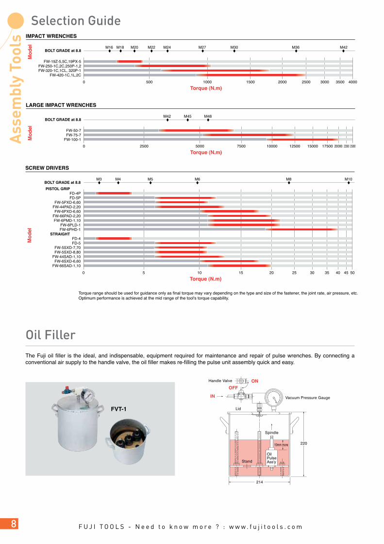
RECOMMENDED TORQUE RANGEThe torque requirement is one of the major factors to be considered when selecting fastening tools. The following graphic presentation shows the recommended torque range of our assembly tools. This is to be used for guidance only as final torque may vary depending on the type and size of the fastener, the joint rate, air pressure, etc.Optimum performance is achieved at the mid range of the tool's torque capability.
according to ISO898/1
Bolt Size Bolt Grade
mm 3.0 4.6 4.8 5.8 8.8 10.9 12.9
M2 0.10 0.13 0.17 0.22 0.35 0.49 0.58
M3 0.35 0.46 0.61 0.77 1.20 1.70 2.10
M4 0.81 1.10 1.40 1.80 2.90 4.00 4.90
M5 0.60 2.20 2.95 3.60 5.70 8.10 9.70
M6 2.80 3.70 4.90 6.10 9.80 14.0 17.0
M8 8.9 10.5 15 24 33 40
M10 17 21 29 47 65 79
M12 30 36 51 81 114 136
M14 48 58 80 128 181 217
M16 74 88 123 197 277 333
Bolt Size Bolt Grade
mm 4.6 4.8 5.8 8.8 10.9 12.9
M18 103 121 172 275 386 463
M20 144 170 240 385 541 649
M22 194 230 324 518 728 874
M24 249 295 416 665 935 1120
M27 360 435 600 961 1350 1620
M30 492 590 819 1310 1840 2210
M36 855 1030 1420 2280 3210 3850
M42 1360 2270 3640 5110 6140
M45 1690 2820 4510 6340 7610
M48 2040 3400 5450 7660 9190
SQUARE DRIVE TYPE FPT-110-1
FLT-4-1FLT-5-1FLT-6-1FLT-7-1FLT-9-1
FLT-11-1FLT-13-1
FLT-20S-1FPT-1660-1
BIT SHANK TYPE FPT-110D-1,10FPT330D-1, 10FPT440D-1, 10
FLT-4D-1FLT-4D-10FLT-5D-1
FLT-5D-10FLT-6D-1
FLT-6D-10
STRAIGHT-SQUARE DRIVE FPT-110S-1FPT-330S-1FPT-440S-1FPT-550S-1FPT-660S-1FPT-770S-1
STRAIGHT-BIT CHANGE FPT-110SD-1,10FPT-330SD-1,10FPT-440SD-1,10FPT-550SD-1,10FPT-660SD-1,10
ANGLE SQUARE DRIVE FPT-440SC-1FPT-550SC-1FPT-660SC-1FPT-770SC-1
GEARED-HEX SOCKET FPT-770SCG-1
0 20 40 60 80 100 120 140 160 180 200 400
PULSE WRENCHES SHUT-OFF TYPE
Torque (N.m)
Mo
del
BOLT GRADE at 8.8

Torque range should be used for guidance only as final torque may vary depending on the type and size of fastener, the joint rate, air pressure etc.Optimum performance is achieved at the mid range of the tool's torque capability.
IMPACT WRENCHES
Torque (N.m)
Mo
del
0 50 100 200 250 300150
BOLT GRADE at 8.8 M6 M8 M10 M12 M14 M16
STRAIGHT FW-44SA-1FW-6SX-6FW-6SX-5
FW-66SA-1FW-8SH-2
FW-10SX-5FW-14SX-5
ANGLE FW-6SCX-6FW-8SCH-2
PISTOL GRIP FW-44PA-2FW-5PX-6FW-6PX-6FW-6PX-5
FW-66PA-2FW-6PM-1FW-6PL-1
FW-6PH-1,11FW-88P-1FW-8PH-3
FW-10PH-2FW-10PX-5FW-10PH-1
FW-14PH-2,3FW-14PX-5FW-14PH-1
PISTOL-SQUARE DRIVE FPW-110-1
FL-4-1FL-5-1FL-6-1FL-7-1FL-9-1
FL-11-1FL-13-1
FPW-1660-1STRAIGHT-SQUARE DRIVE
FPW-2220S-1FPW-110S-1FPW-330S-1FPW-440S-1FPW-550S-1FPW-660S-1FPW-770S-1
PISTOL-BIT SHANK FPW-110D-1,10
FL-4D-1,10 FL-5D-1,10FL-6D-1,10
STRAIGHT-BIT SHANK FPW-110SD-1,10FPW-330SD-1,10FPW-440SD-1,10FPW-550SD-1,10FPW-660SD-1,10
ANGLE-SQUARE DRIVE FPW-440SC-1FPW-550SC-1FPW-660SC-1FPW-770SC-1
GEARED-HEX SOCKET FPW-770SCG-1
0 50 100 150 200 250 300
500
PULSE WRENCHES
Torque (N .m)
Mo
del
BOLT GRADE at 8.8 M4 M5 M6 M8 M10 M12 M14 M16 M18 M20
IMPACT WRENCHES
Torque (N.m)
Mo
del
0 500 1000 1500 400025002000 3000 3500
BOLT GRADE at 8.8 M16 M18 M20 M22 M24 M27 M30 M36 M42
FW-19Z-5,5C,19PX-5FW-250-1C,2C,250P-1,2FW-320-1C,1CL, 320P-1
FW-420-1C,1L,2C
LARGE IMPACT WRENCHES
Torque (N.m)
Mo
del
0 5000 7500 150001250010000 250002500 17500 20000 22500
BOLT GRADE at 8.8 M42 M45 M48
FW-50-7FW-75-7
FW-100-1
Torque range should be used for guidance only as final torque may vary depending on the type and size of the fastener, the joint rate, air pressure, etc.Optimum performance is achieved at the mid range of the tool's torque capability.
The Fuji oil filler is the ideal, and indispensable, equipment required for maintenance and repair of pulse wrenches. By connecting a conventional air supply to the handle valve, the oil filler makes re-filling the pulse unit assembly quick and easy.
FVT-1
Handle Valve
Vacuum Pressure Gauge
OilPulseAss'y
Lid
Spindle
220
214
10mm more
Stand
IN
OFFON
SCREW DRIVERS
Torque (N.m)
Mo
del
0 5 10 20 503525 30 4015 45
BOLT GRADE at 8.8 M3 M4 M5 M6 M8 M10
PISTOL GRIP FD-4PFD-5P
FW-5PXD-6,60FW-44PAD-2,20FW-6PXD-6,60
FW-66PAD-2,20FW-6PMD-1,10
FW-6PLD-1FW-6PHD-1
STRAIGHT FD-4FD-5
FW-5SXD-7,70FW-5SXD-8,80
FW-44SAD-1,10FW-6SXD-6,60
FW-66SAD-1,10
2 TWO STAGE / SQUEEZING TYPE THROTTLE VALVE MECHANISM
3 REVERSE VALVE LEVER
4 AIR REGULATOR
6 BIT SHANK TYPE ANVIL FOR SCREW DRIVERS
7 CLUTCH MECHANISM-IMPACT WRENCHES AND DRIVERS
5 SQUARE DRIVE ANVIL
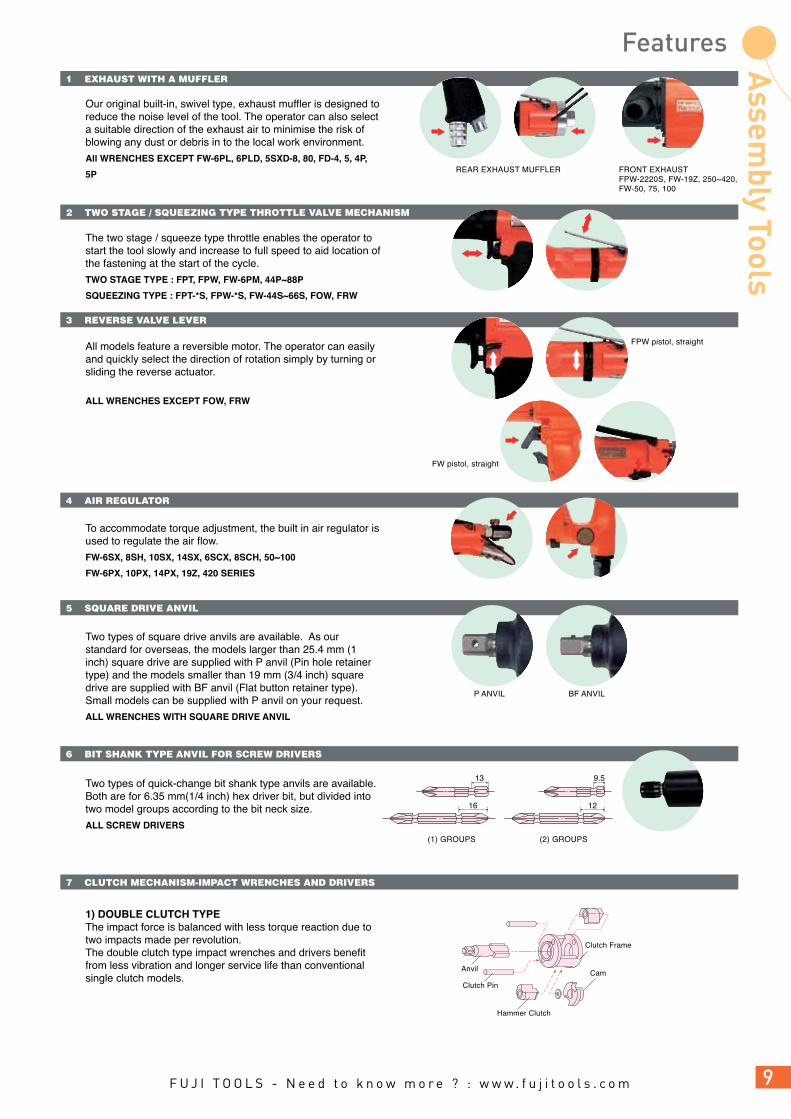
Our original built-in, swivel type, exhaust muffler is designed to reduce the noise level of the tool. The operator can also select a suitable direction of the exhaust air to minimise the risk of blowing any dust or debris in to the local work environment.
All WRENCHES EXCEPT FW-6PL, 6PLD, 5SXD-8, 80, FD-4, 5, 4P,
5P
The two stage / squeeze type throttle enables the operator to start the tool slowly and increase to full speed to aid location of the fastening at the start of the cycle.
TWO STAGE TYPE : FPT, FPW, FW-6PM, 44P~88P
SQUEEZING TYPE : FPT-*S, FPW-*S, FW-44S~66S, FOW, FRW
All models feature a reversible motor. The operator can easily and quickly select the direction of rotation simply by turning or sliding the reverse actuator.
ALL WRENCHES EXCEPT FOW, FRW
To accommodate torque adjustment, the built in air regulator is used to regulate the air flow.
FW-6SX, 8SH, 10SX, 14SX, 6SCX, 8SCH, 50~100
FW-6PX, 10PX, 14PX, 19Z, 420 SERIES
Two types of square drive anvils are available. As our standard for overseas, the models larger than 25.4 mm (1 inch) square drive are supplied with P anvil (Pin hole retainer type) and the models smaller than 19 mm (3/4 inch) square drive are supplied with BF anvil (Flat button retainer type). Small models can be supplied with P anvil on your request.
ALL WRENCHES WITH SQUARE DRIVE ANVIL
Two types of quick-change bit shank type anvils are available. Both are for 6.35 mm(1/4 inch) hex driver bit, but divided into two model groups according to the bit neck size.
ALL SCREW DRIVERS
1) DOUBLE CLUTCH TYPEThe impact force is balanced with less torque reaction due to two impacts made per revolution.The double clutch type impact wrenches and drivers benefit from less vibration and longer service life than conventional single clutch models.
1 EXHAUST WITH A MUFFLER
REAR EXHAUST MUFFLER
P ANVIL BF ANVIL
(1) GROUPS (2) GROUPS
FPW pistol, straight
FW pistol, straight
FRONT EXHAUSTFPW-2220S, FW-19Z, 250~420,FW-50, 75, 100
9.5
12
13
16
Cam
Clutch Frame
Clutch Pin
Anvil
Hammer Clutch
8 HANDLE PROTECTOR
9 DUAL CHAMBER MOTOR
10 2-BLADE PULSE UNIT
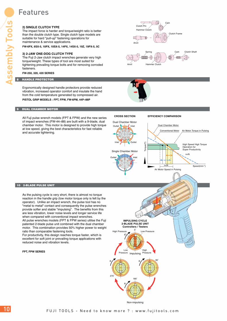
2) SINGLE CLUTCH TYPEThe impact force is harder and torque/weight ratio is better than the double clutch type. Single clutch type models are suitable for hard "pull-up" fastening operations for maintenance & service applications.
FW-6PX, 6SX-5, 10PX, 10SX-5, 14PX, 14SX-5, 19Z, 19PX-5, 5C
3) 2-JAW ONE-DOG CLUTCH TYPEThe Fuji 2-Jaw clutch impact wrenches generate very high torque/weight. These types of tool are most suited for tightening prevailing torque bolts and for removing corroded fasteners.
FW-250, 320, 420 SERIES
Ergonomically designed handle protectors provide reduced vibration, increased operator comfort and insulate the hand from the cold temperature generated by compressed air.
PISTOL GRIP MODELS : FPT, FPW, FW-6PM, 44P~88P
All Fuji pulse wrench models (FPT & FPW) and the new series of impact wrenches (FW-44~88) are built with a 9-blade, dual chamber motor. This motor is designed to provide high torque at low speed, giving the best characteristics for fast reliable and accurate tightening.
As the pulsing cycle is very short, there is almost no torque reaction in the handle grip (low motor torque only is felt by the operator). Unlike an impact wrench, the pulse tool has no "metal to metal" contact and consequently the pulse wrenches provide softer and stable "impulsing". The benefits from this are less vibration, lower noise levels and longer service life when compared with conventional impact wrenches.All pulse wrenches models (FPT & FPW series) utilise the Fuji patented 2-blade pulse unit combined with the dual chamber motor. This combination provides 50% higher power to weight ratio than comparable fastening tools. For productivity, this design reaches torque faster, which is excellent for soft joint or prevailing torque applications with reduced noise and vibration levels.
FPT, FPW SERIES
Dual Chamber Motor
InletOutlet
InletOutlet
Low Pressure0˚
180˚
90˚
HighPressure
Inlet Outlet
Clutch Shaft
Hammer ClutchAnvil
CamSpring
Dual Chamber Motor
Impulsing
IMPULSING CYCLE2-BLADE PULSE UNITControllers / Testers
Non-impulsing
EFFICIENCY COMPARISONCROSS SECTION
Conventional Motor
Single Chamber Motor
Air Motor Torque in Pulsing
High Speed High TorqueOperation forSuper Productivity
Air Motor Speed in Pulsing
n<N
n<N
Speed(min-1)
Torq
ue(T
)
R
R
270˚
R
R
LowPressure
High Pressure
Cam
Hammer Clutch
Clutch Frame
Clutch Pin
Anvil

FPT-1110~1660
"FPT and FLT Series" are provided with Fuji patented original shut-off control mechanism having a dual chamber motor and 2-blade pulsing mechanism. It is designed for giving high torque at low speed, which gives the best characteristics for fast, reliable and accurate tightening. FPT and FLT Series contribute to high productivity, quality improvement, working environment improvement, and operator fatigue minimization in various industries.
FPT-330S~660SFPT-110S FPT-770S
Models to be operated at air pressure 0.5MPa to 0.6MPa (5.0 to 6.3 bar)
Straight ModelsFPT-110S-1 M4~M5 4~7 0.4~0.7 3.0~5.2 4,500 9.5 3/8 236.5 9 5/16 0.85 1.9 0.20 7.1FPT-330S-1 M5~M6 6~10 0.6~1.0 4.4~7.4 4,400 9.5 3/8 249 9 13/16 1.1 2.4 0.35 12.3FPT-440S-1 M5~M6 8~13 0.8~1.3 5.9~9.6 5,000 9.5 3/8 250 9 27/32 1.1 2.4 0.35 12.3FPT-550S-1 M6~M8 12~20 1.2~2.0 8.9~14.8 5,000 9.5 3/8 250 9 27/32 1.1 2.4 0.35 12.3FPT-660S-1 M6~M8 20~30 2.0~3.1 14.8~22.1 5,000 9.5 3/8 262 10 21/64 1.1 2.4 0.50 17.6FPT-770S-1 M8~M10 30~45 3.1~4.6 22.1~33.2 5,500 9.5 3/8 273.5 10 49/64 1.6 3.5 0.45 15.9Pistol Grip ModelsFPT-110-1 M5~M6 4~7 0.4~0.7 3.0~5.2 6,000 9.5 3/8 194.5 7 21/32 0.95 2.1 0.20 7.1FLT-4-1 M5~M6 5~12 0.5~1.2 3.6~8.8 6,200 9.5 3/8 181 7 1/8 0.97 2.1 0.40 14.1FLT-5-1 M6~M8 11~24 1.1~2.4 8.1~17.7 6,500 9.5 3/8 181 7 1/8 0.97 2.1 0.45 15.8FLT-6-1 M8~M10 22~35 2.2~3.5 16.2~25.8 6,300 9.5 3/8 192 7 19/32 1.00 2.2 0.55 19.4FLT-7-1 M8~M10 30~60 3.0~6.1 22.1~44.2 6,100 9.5 3/8 189.5 7 29/64 1.10 2.4 0.60 21.1FLT-9-1 M10 50~85 5.1~8.6 36.8~62.6 5,300 12.7 1/2 209 8 15/64 1.60 3.5 0.68 24.0FLT-11-1 M10~M12 70~130 7.1~13.2 51.6~95.8 5,000 12.7 1/2 217.5 8 9/16 1.85 4.1 0.80 28.2FLT-13-1 M12~M14 90~160 9.1~16.3 66.3~118 3,400 12.7 1/2 227.5 8 61/64 2.10 4.6 0.85 30.0FLT-20S-1 M18~M20 200~400 20.4~40.8 147.5~295 2,500 19.0 3/4 405 15 3/32 8.80 19.4 1.3 45.8FPT-1660-1 M16~M18 150~210 15.3~21.4 110.6~154.9 2,800 19.0 3/4 266 10 31/64 4.4 9.7 1.2 42.4
Model
mm inmm inmm kg lb m3/min ft3/minN • m kgf • m ft • lb min-1
FreeSpeed
SquareDrive Size
Air Consumption(at Load)
OverallLength
RecommendedTorque RangeBolt Size
Weight(without socket)
*Use all above models at 0.5-0.63 MPa (5.0 to 6.3 bar) air pressure but FPT-110 series at 0.4-0.63 MPa (4.0-6.3 bar) air pressure.*Performance figures are at 0.63 MPa (6.3 bar) air pressure. *Air Inlet Thread Size: BSP or NPT 1/4", (FPT-1660) BSP or NPT 3/8".*Air Hose Size: (FPT-110S, 330S, 440S, 550S, FLT-4-1, 5-1) 6.3mm (1/4"). (660S, 770S, 1660-1, FLT-6-1, 7-1, 9-1, 11-1, 13-1) 9.5mm (3/8"), (FLT-20S-1) 12.7mm (1/2").
FLT-4 FLT-5 FLT-6
SQUARE DRIVE TYPE

FPT-330SD~660SDFPT-110SD
*Use all above models at 0.5-0.63 MPa (5.0 to 6.3 bar) air pressure but FPT-110 series at 0.4-0.63 MPa (4.0-6.3 bar) air pressure.*Performance figures are at 0.63 MPa (6.3 bar) air pressure. *Air Inlet Thread Size: or NPT 1/4".*Air Hose Size: (FPT-110SD, 330SD, 440SD, 550SD, 110D, 330D, FLT-4D-1, 4D-10, 5D-1, 5D-10) 6.3mm (1/4"). (FPT660SD, FLT-6D-1, FLD-6D-10) 9.5mm (3/8").
Model
mm inmm mm in kg lb m3/min ft3/minN • m kgf • m ft • lb min-1
FreeSpeed
Air Consumption(at Load)
OverallLength
RecommendedTorque Range
Bit ShankSize
FPT-***SD-1, ***D-1,1LA:9.5mm B:12mm
FPT-***SD-10, ***D-10,10LA:13mm B:16mm
BIT SHANK TYPE
Models to be operated at air pressure 0.5MPa to 0.63MPa (5.0 to 6.3 bar)
Bolt Size Weight(without socket)
Angle Head ModelsFPT-440SC-1 M5~M6 6~11 0.6~1.1 4.4~8.1 4,500 9.5 3/8 280 11 1/32 1.46 3.2 0.35 12.4 FPT-550SC-1 M6 10~17 1.0~1.7 7.4~12.5 4,800 9.5 3/8 280 11 1/32 1.46 3.2 0.35 12.4 FPT-660SC-1 M6~M8 15~25 1.5~2.6 11.1~18.4 4,700 9.5 3/8 292 11 1/2 1.54 3.4 0.5 17.7 FPT-770SC-1 M8 20~35 2.0~3.6 14.8~25.8 5,500 9.5 3/8 306 12 3/64 2.3 5.1 0.45 15.9
Model
mm inmm mm in kg lb m3/min ft3/minN • m kgf • m ft • lb min-1
FreeSpeed
Air Consumption(at Load)
OverallLength
*Air Inlet Thread Size: BSP or NPT 1/4". *Air Hose Size: 6.3mm (1/4"). (660SC, 770SC) 9.5mm (3/8").
RecommendedTorque Range
Square DriveSize
Models to be operated at air pressure 0.5MPa to 0.63MPa (5.0 to 6.3 bar)
Bolt Size Weight(without socket)
Bit Size
A
B
FPT-440SC~660SC FPT-770SC-1
Straight ModelsFPT-110SD-1(10) M4~M5 4~7 0.4~0.7 3.0~5.2 4,500 6.35 1/4 240 9 29/64 0.85 1.9 0.20 7.1FPT-330SD-1(10) M5~M6 6~10 0.6~1.0 4.4~7.4 4,400 6.35 1/4 249 9 13/16 1.1 2.4 0.35 12.3FPT-440SD-1(10) M5~M6 8~13 0.8~1.3 5.9~9.6 5,000 6.35 1/4 251 9 57/64 1.1 2.4 0.35 12.3FPT-550SD-1(10) M6~M8 12~20 1.2~2.0 8.9~14.8 5,000 6.35 1/4 251 9 57/64 1.1 2.4 0.35 12.3FPT-660SD-1(10) M6~M8 15~28 1.5~2.9 11.1~20.7 5,000 6.35 1/4 262 10 21/64 1.1 2.4 0.50 17.6Pistol Grip ModelsFPT-110D-1(10) M5~M6 4~7 0.4~0.7 3.0~5.2 6,000 6.35 1/4 197.5 7 25/32 0.95 2.1 0.20 7.1FPT-330-1 M5~M6 6~11 0.6~1.1 4.4~8.1 6,000 9.5 3/8 198 7 51/64 1.2 2.6 0.39 13.8FPT-440D-1(10) M6 10~16 1.0~1.6 7.4~11.8 6,700 6.35 1/4 193 7 39/64 1.2 2.6 0.35 12.3FLT-4D-1 M6 14~20 1.4~2.0 10.3~14.7 6,700 6.35 1/4 140 5 3/64 0.79 1.7 0.36 12.7FLT-4D-10 M6 14~20 1.4~2.0 10.3~14.7 6,700 6.35 1/4 140 5 3/64 0.79 1.7 0.36 12.7 FLT-5D-1 M6~M8 18~32 1.7~3.2 13.2~23.6 6,300 6.35 1/4 140 5 3/64 0.79 1.7 0.40 14.1FLT-5D-10 M6~M8 18~32 1.7~3.2 13.2~23.6 6,300 6.35 1/4 140 5 3/64 0.79 1.7 0.40 14.1FLT-6D-1 M8 25~42 2.5~4.2 18.4~30.9 6,700 6.35 1/4 152 5 63/64 0.83 1.8 0.42 14.8 FLT-6D-10 M8 25~42 2.5~4.2 18.4~30.0 6,700 6.3 1/4 152 5 63/64 0.83 1.8 0.42 14.8
FLT-4 FLT-5 FLT-6
SQUARE DRIVE TYPE

FPT-770SCG-1 M6 17~24 1.7~2.4 12.5~17.7 6,400 12 15/32 378 14 7/8 2.6 5.7 0.45 15.9 9.5 3/8
Model
mm in inmm mminmm kg lb m3/min ft3/minN • m kgf • m ft • lb min-1
FreeSpeed
Air HoseSize
Socket HexSize
Air Consumption(at Load)Overall Length
RecommendedTorque RangeBolt Size Weight
*Air Inlet Thread Size: BSP or NPT 1/4".
FPT-770SCG-1
The Fuji Geared Pulse Wrenches Shut-Off type provides high power in combination with low noise and vibration though the Dual Chamber Air Motor & Gear-drive angle head.The ergonomic design reduces the reaction forces experienced by the operator throughout the torque range.
Models to be operated at air pressure 0.5MPa to 0.63MPa (5.0 to 6.3 bar)

FPW-1660
FPW-110-1
FL-.D
Featured with dual chamber air motor, FPW and FL series pulse wrenches are designed to generate higher torque and yet reducing vibration, torque reaction and noise levels. Combined with 2-blade impulsing mechanism, 9-blade dual chamber motor creates about 50% higher power-to-weight ratio than our former series of the same physical size. The reduction of vibration and torque reaction helps reduce operator fatigue and other problems associated with repeated vibration or impact motion.
SQUARE DRIVE TYPE
Pistol Grip Models
FPW-110-1 M4~M5 7.5~13 0.8~1.3 5.5~9.6
4,500 9.5 3/8 143 5 41/64 0.75 1.7 0.20 7.1 6.3 1/4 (2~7.5) (0.2~0.8) (1.4~5.5)FL-4-1 M6 16~24 1.6~2.4 11.8~17.7 6,700 9.5 3/8 139.5 5 31/64 0.79 1.7 0.36 12.7 6.3 1/4 FL-5-1 M6~M8 20~40 2.0~4.0 14.7~29.5 6,300 9.5 3/8 139.5 5 31/64 0.79 1.7 0.40 14.1 6.3 1/4FL-6-1 M8 28~56 2.8~5.6 20.6~41.3 6,700 9.5 3/8 151.5 5 31/32 0.83 1.8 0.42 14.8 9.5 3/8FL-7-1 M8~M10 34~60 3.4~6.1 25.0~44.2 6,100 9.5 3/8 155 6 7/64 1.02 2.2 0.60 21.1 9.5 3/8FL-9-1 M10 52~96 5.3~9.7 38.3~70.8 5,000 12.7 1/2 173 6 13/16 1.45 3.2 0.65 22.9 9.5 3/8FL-11-1 M10~M12 80~136 8.1~13.8 59.0~100.3 5,000 12.7 1/2 184 7 15/64 1.80 4.0 0.80 28.2 9.5 3/8FL-13-1 M12~M14 120~172 12.2~17.5 88.5~126.8 3,800 12.7 1/2 192 7 9/16 2.10 4.6 0.85 30.0 9.5 3/8FPW-1660-1 M16~M18 160~270 16.3~27.5 118~199.1 3,000 19.0 3/4 243 9 37/64 3.80 8.4 1.20 42.4 9.5 3/8
Model
mm in inmm mminmm kg lb m3/min ft3/minN • m kgf • m ft • lb min-1
FreeSpeed
Air HoseSize
Square DriveSize
Air Consumption(at Load)
Overall Length(without socket)
RecommendedTorque RangeBolt Size
Weight(without socket)
*Air Inlet Thread Size: BSP or NPT 1/4", (FPW-1660)PT or NPT 3/8".*Figures in ( ) can be obtained at the position of "L" mark on the regulator knob, but for another, at "H" mark.
BIT SHANK TYPE
Pistol Grip Models
FPW-110D-1 M4~M5 7~11 0.7~1.1 5.2~8.1
4,500 6.35 1/4 149 5 7/8 0.76 1.7 0.20 7.1 6.3 1/4 (2~7) (0.2~0.7) (1.4~5.1)FPW-110D-10 M4~M5 7~11 0.7~1.1 5.2~8.1 4,500 6.35 1/4 149 5 7/8 0.76 1.7 0.20 7.1 6.3 1/4FL-4D-1 M6 14~20 1.4~2.0 10.3~14.7 6,700 6.35 1/4 140 5 3/64 0.79 1.7 0.36 12.7 6.3 1/4FL-4D-10 M6 14~20 1.4~2.0 10.3~14.7 6,700 6.35 1/4 140 5 3/64 0.79 1.7 0.36 12.7 6.3 1/4FL-5D-1 M6~M8 18~32 1.8~3.2 13.2~23.6 6,300 6.35 1/4 140 5 3/64 0.79 1.7 0.40 14.1 6.3 1/4FL-5D-10 M6~M8 18~32 1.8~3.2 13.2~23.6 6,300 6.35 1/4 140 5 3/64 0.79 1.7 0.40 14.1 6.3 1/4FL-6D-1 M8 25~42 2.5~4.2 18.4~30.9 6,700 6.35 1/4 152 5 63/64 0.83 1.8 0.42 14.8 6.3 1/4FL-6D-10 M8 25~42 2.5~4.2 18.4~30.9 6,700 6.35 1/4 152 5 63/64 0.83 1.8 0.42 14.8 6.3 1/4
Model
mm in inmm mminmm kg lb m3/min ft3/minN • m kgf • m ft • lb min-1
FreeSpeed
Air HoseSize
Bit ShankSize
Air Consumption(at Load)
Overall Length(without socket)
RecommendedTorque RangeBolt Size
Weight(without socket)
*Air Inlet Thread Size: BSP or NPT 1/4".*Figures in ( ) can be obtained at the position of "L" mark on the regulator knob, but for another, at "H" mark.
FPW-110D-1
FL-4 FL-5 FL-6

FPW-110S~660S FPW-770S-1
FPW-110SD FPW-330SD~660SD
SQUARE DRIVE TYPE
Straight ModelsFPW-110S-1 M4 2~7.5 0.2~0.8 1.5~5.5 3,200 9.5 3/8 218 8 19/32 0.65 1.4 0.20 7.1 6.3 1/4FPW-330S-1 M5 13~22 1.3~2.2 9.6~16.2 4,400 9.5 3/8 226 8 57/64 0.87 1.9 0.30 10.6 6.3 1/4FPW-440S-1 M4~M6 20~34 2.0~3.5 14.8~25.1 5,500 9.5 3/8 226 8 57/64 0.87 1.9 0.35 12.4 6.3 1/4FPW-550S-1 M6~M8 27~44 2.8~4.5 19.9~32.5 5,700 9.5 3/8 226 8 57/64 0.87 1.9 0.37 13.1 6.3 1/4FPW-660S-1 M6~M8 34~54 3.5~5.5 25.1~39.8 5,800 9.5 3/8 238 9 3/8 0.95 2.1 0.50 17.7 9.5 3/8FPW-770S-1 M8 44~76 4.5~7.8 32.5~56.1 6,300 9.5 3/8 240 9 7/16 1.25 2.7 0.50 17.7 9.5 3/8FPW-2220S-1 M18~M20 300~500 30.6~51.0 221.3~368.8 2,500 19.0 3/4 350 10 13/16 7.00 15.4 1.30 45.9 12.7 1/2
Model
mm in inmm mminmm kg lb m3/min ft3/minN • m kgf • m ft • lb min-1
FreeSpeed
Air HoseSize
Square DriveSize
Air Consumption(at Load)
Overall Length(without socket)
RecommendedTorque RangeBolt Size
Weight(without socket)
*Air Inlet Thread Size: BSP or NPT 1/4", (FPW-2220S) BSP or NPT 1/2".
BIT SHANK TYPE
Straight ModelsFPW-110SD-1 M4 2~7 0.2~0.7 1.5~5.2 3,200 6.35 1/4 224 8 53/64 0.65 1.4 0.20 7.1 6.3 1/4FPW-110SD-10 M4 2~7 0.2~0.7 1.5~5.2 3,200 6.35 1/4 224 8 53/64 0.65 1.4 0.20 7.1 6.3 1/4FPW-330SD-1 M5 12~17 1.2~1.7 8.9~12.5 4,400 6.35 1/4 226 8 57/64 0.88 1.9 0.30 10.6 6.3 1/4FPW-330SD-10 M5 12~17 1.2~1.7 8.9~12.5 4,400 6.35 1/4 226 8 57/64 0.88 1.9 0.30 10.6 6.3 1/4FPW-440SD-1 M4~M6 15~25 1.5~2.6 11.1~18.4 5,500 6.35 1/4 226 8 57/64 0.88 1.9 0.35 12.4 6.3 1/4FPW-440SD-10 M4~M6 15~25 1.5~2.6 11.1~18.4 5,500 6.35 1/4 226 8 57/64 0.88 1.9 0.35 12.4 6.3 1/4FPW-550SD-1 M4~M6 20~34 2.0~3.5 14.8~25.1 5,700 6.35 1/4 226 8 57/64 0.88 1.9 0.37 13.1 6.3 1/4FPW-550SD-10 M4~M6 20~34 2.0~3.5 14.8~25.1 5,700 6.35 1/4 226 8 57/64 0.88 1.9 0.37 13.1 6.3 1/4FPW-660SD-1 M6~M8 25~37 2.6~3.8 18.4~27.3 5,800 6.35 1/4 238 9 3/8 0.95 2.1 0.50 17.7 9.5 3/8FPW-660SD-10 M6~M8 25~37 2.6~3.8 18.4~27.3 5,800 6.35 1/4 238 9 3/8 0.95 2.1 0.50 17.7 9.5 3/8
Model
mm in inmm mminmm kg lb m3/min ft3/minN • m kgf • m ft • lb min-1
FreeSpeed
Air HoseSize
Bit shankSize
Air Consumption(at Load)
Overall Length(without socket)
RecommendedTorque RangeBolt Size
Weight(without socket)
*Air Inlet Thread Size: BSP or NPT 1/4".
FPW-2220S-1
FPW-***SD-1, FPW-***D-1,2,3,4A:9.5mm B:12mm
FPW-***SD-10, FPW-***D-10,20,30,40A:13mm B:16mm
Bit Size
A
B

FPW-770SCG-1 M4~M6 21~30 2.1~3.1 15.5~22.1 7,000 12 15/32 343 13 33/64 2.0 4.4 0.50 17.7 9.5 3/8
Model
mm in inmm mminmm kg lb m3/min ft3/minN • m kgf • m ft • lb min-1
FreeSpeed
Air HoseSize
Socket HexSize
Air Consumption(at Load)Overall Length
RecommendedTorque RangeBolt Size Weight
*Air Inlet Thread Size: BSP or NPT 1/4".
FPW-770SCG-1
The Fuji Geared Pulse Wrenches Shut-Off type provides high power in combination with low noise and vibration through the Dual Chamber Air Motor & Gear-drive angle head.The ergonomic design reduces the reaction forces experienced by the operator throughout the torque range.
FPW-770SC-1FPW-440SC~660SC
SQUARE DRIVE TYPE
Angle Head ModelsFPW-440SC-1 M4~M6 13~24 1.3~2.4 9.6~17.7 5,000 9.5 3/8 255 10 3/64 1.28 2.8 0.39 13.8 6.3 1/4FPW-550SC-1 M6~M8 22~35 2.2~3.6 16.2~25.8 5,500 9.5 3/8 255 10 3/64 1.29 2.8 0.39 13.8 6.3 1/4FPW-660SC-1 M6~M8 25~43 2.6~4.4 18.4~31.7 5,500 9.5 3/8 267 10 33/64 1.40 3.1 0.48 16.9 9.5 3/8FPW-770SC-1 M8 33~50 3.4~5.1 24.3~36.9 6,300 9.5 3/8 271 10 43/64 1.70 3.7 0.50 17.7 9.5 3/8
Model
mm in inmm mminmm kg lb m3/min ft3/minN • m kgf • m ft • lb min-1
FreeSpeed
Air HoseSize
Square DriveSize
Air Consumption(at Load)
Overall Length(without socket)
RecommendedTorque RangeBolt Size
Weight(without socket)
*Air Inlet Thread Size: BSP or NPT 1/4".

Fuji Impact Wrenches FW-44~88 have 9-blade dual chamber motor and double clutch type impact mechanism. They are designed for giving high torque at low speed, which give the best characteristics for fast reliable and accurate tightening. These models are provided with two types of lubricant in clutch part, FW-44PA~66PA and FW-44SA~66SA series are with oil (Oil Bath type) which features long service life and FW-44P~88P and FW-44S~66S are with conventional grease. Both series are suitable for self tapping type soft joint.
FW-44SA~66SA
Model
mm in inmmN • mft • lbkgf • mN • m mminmm kg lb m3/min ft3/minmin-1
FreeSpeed
Max.Torque
RecommendedTorque Range
Air HoseSize
Square DriveSize
Air Consumption(at Load)
Overall Length(without socket)
BoltSize
Weight(without socket)
*Marked • are oil bath types. *All Models are double clutch types.*Air Inlet Thread Size: BSP or NPT 1/4".
•FW-44SA-1 M5 8~16 0.8~1.6 5.9~11.8 20 5,700 9.5 3/8 207 8 5/32 0.66 1.4 0.35 12.4 6.3•FW-66SA-1 M6 14~26 1.4~2.7 10.3~19.2 32 5,000 9.5 3/8 212 8 11/32 0.78 1.7 0.37 13.1 6.3
Straight Model
FW-88P-1FW-44PA~66PA
Model
mm in inmm mminmm kg lb m3/min ft3/minmin-1
FreeSpeed
Air HoseSize
Square DriveSize
Air Consumption(at Load)
Overall Length(without socket)
BoltSize
Weight(without socket)
*Marked • are oil bath types. *All Models are double clutch types.*Air Inlet Thread Size: BSP or NPT 1/4".
N • mft • lbkgf • mN • m
Max.Torque
RecommendedTorque Range
Pistol Grip Models
•FW-44PA-2 M5 8~16 0.8~1.6 5.9~11.8 20 6,500 9.5 3/8 131 5 5/32 0.78 1.7 0.60 21.2 6.3•FW-66PA-2 M6 14~26 1.4~2.7 10.3~19.2 32 5,000 9.5 3/8 137 5 25/64 0.88 1.9 0.48 16.9 6.3FW-88P-1 M8 27~50 2.8~5.1 19.9~36.9 70 5,300 12.7 1/2 163 6 27/64 1.40 3.1 0.64 22.5 9.5
9.5mm(3/8")~12.7mm(1/2")
1/41/43/8
1/41/4

FW-6PM-1
FW-6PX-5,6 FW-6PH-1,11 FW-8PH-3
FW-5PX-6FW-6PL-1
Fuji Impact Wrenches are suitable for various fastening and unfastening operations. The combination of high torque and fast run down minimise operator fatigue.
•FW-5PX-6 M5 8~13 0.8~1.3 5.9~9.6 18 12,000 9.5 3/8 150 5 29/32 0.80 1.8 0.20 7.1 6.3•FW-6PM-1 M6 14~26 1.4~2.7 10.3~19.2 32 8,500 9.5 3/8 140 5 33/64 0.92 2.0 0.53 18.7 9.5•FW-6PL-1 M6 14~26 1.4~2.7 10.3~19.2 32 10,000 9.5 3/8 175 6 57/64 0.90 2.0 0.20 7.1 9.5FW-6PX-5 M6 11~23 1.1~2.3 8.1~17.0 30 10,000 9.5 3/8 156 6 9/64 1.20 2.6 0.28 9.9 9.5
•FW-6PX-6 M6 10~18 1.0~1.8 7.4~13.3 25 10,000 9.5 3/8 156 6 9/64 1.20 2.6 0.28 9.9 9.5•FW-6PH-1 M8 27~40 2.8~4.1 19.9~29.5 60 9,000 9.5 3/8 147 5 25/32 1.35 3.0 0.35 12.4 9.5•FW-6PH-11 M8 27~40 2.8~4.1 19.9~29.5 60 9,000 12.7 1/2 152 6 1.40 3.1 0.35 12.4 9.5•FW-8PH-3 M10 42~80 4.3~8.2 31.0~59.0 130 7,500 12.7 1/2 162 6 3/8 1.50 3.3 0.40 14.1 9.5FW-10PX-5 M10 50~100 5.1~10.2 36.9~73.8 150 8,000 12.7 1/2 182 7 11/64 2.30 5.0 0.40 14.1 9.5
•FW-10PH-1 M10 63~120 6.4~12.2 46.5~88.5 160 7,500 12.7 1/2 179 7 3/64 2.00 4.4 0.45 15.8 9.5•FW-10PH-2 M10 47~93 4.8~9.5 34.7~68.6 113 7,500 12.7 1/2 179 7 3/64 2.00 4.4 0.45 15.8 9.5FW-14PX-5 M14 100~150 10.2~15.3 73.8~110.6 190 6,500 12.7 1/2 197 7 3/4 3.00 6.6 0.40 14.1 9.5
•FW-14PH-1 M14 85~140 8.7~14.3 62.7~103.3 180 7,500 12.7 1/2 202 7 15/16 2.56 5.7 0.60 21.2 9.5•FW-14PH-2 M14 85~140 8.7~14.3 62.7~103.3 180 7,500 12.7 1/2 202 7 15/16 2.56 5.7 0.60 21.2 9.5•FW-14PH-3 M14 85~140 8.7~14.3 62.7~103.3 180 7,500 15.9 5/8 202 7 15/16 2.56 5.7 0.60 21.2 9.5
Model
mm in inmm mminmm kg lb m3/min ft3/minmin-1
FreeSpeed
Air HoseSize
Square DriveSize
Air Consumption(at Load)
Overall Length(without socket)
BoltSize
Weight(without socket)
*Marked • are double clutch types. Others are single clutch types.*Air Inlet Thread Size: BSP or NPT 1/4".
Small Size Pistol Grip Models
FW-10PH-1,2FW-10PX-5 FW-14PX-5
FW-14PH-1,2 FW-14PH-3
9.5mm (3/8")~15.9mm (5/8")
1/43/83/83/83/83/83/83/83/83/83/83/83/83/83/8
N • mft • lbkgf • mN • m
Max.Torque
RecommendedTorque Range

Small Size Straight Models
Angle Head Models
FW-8SH-2
FW-14SX-5FW-10SX-5
FW-6SX-5,-6
FW-6SX-5 M6 11~23 1.1~2.3 8.1~17.0 30 10,000 9.5 3/8 223 8 25/32 1.10 2.4 0.30 10.6 9.5•FW-6SX-6 M6 10~18 1.0~1.8 7.4~13.3 25 10,000 9.5 3/8 223 8 25/32 1.10 2.4 0.30 10.6 9.5•FW-8SH-2 M10 35~67 3.6~6.8 25.8~49.4 93 8,000 12.7 1/2 306 12 3/64 1.70 3.7 0.40 14.1 9.5FW-10SX-5 M10 50~100 5.1~10.2 36.9~73.8 150 8,000 12.7 1/2 317 12 31/64 2.20 4.8 0.40 14.1 9.5FW-14SX-5 M14 100~150 10.2~15.3 73.8~110.6 190 6,500 12.7 1/2 356 14 1/64 3.00 6.6 0.50 17.7 9.5
Model
mm in inmminmmmm kg lb m3/min ft3/minmin-1
FreeSpeed
Air HoseSize
RecommendedTorque Range
Air Consumption(at Load)
Overall Length(without socket)
BoltSize
Weight(without socket)
*Marked • are double clutch types. Others are single clutch types.*Air Inlet Thread Size: BSP or NPT 1/4".
•FW-6SCX-6 M6 9~18 0.9~1.8 6.6~13.3 20 8,000 9.5 3/8 261 10 9/32 1.60 3.5 0.30 10.5 9.5•FW-8SCH-2 M10 33~67 3.4~6.8 24.3~49.4 87 7,500 12.7 1/2 347 13 21/32 2.70 5.9 0.40 14.1 9.5
Model
mm in inmm mminmm kg lb m3/min ft3/minmin-1
FreeSpeed
Max.Torque
Max.Torque
Air HoseSize
RecommendedTorque Range
Square DriveSize
Square DriveSize
Air Consumption(at Load)
Overall Length(without socket)
BoltSize
Weight(without socket)
*Marked • are double clutch types.*Air Inlet Thread Size: BSP or NPT 1/4".
FW-6SCX-6 FW-8SCH-2
Model Models
mm ininin mmmminmm kg lb
SquareDrive Size
Weight(without socket)
Angle HeadHeight
Side toCenter
OverallLength
CA-14A 24.5 31/32 12.7 1/2 84 3 5/16 146 5 3/4 1.4 3.0 FW-14PX,14SX Series
IMPACT WRENCHES+CORNER ATTACHMENT
The Corner Attachment CA-14A can be mounted on straight or pistol grip type impact wrenches FW-14PX, 14SX to access fastening in confined spaces.
CA-14A + FW-14SX-5CA-14A
9.5mm (3/8")~12.7mm (1/2")
ft • lbkgf • mN • m
ft • lbkgf • mN • m
N • m
N • m
3/83/83/83/83/8
3/83/8

Medium Size Straight Models
FW-19Z-5
FW-420-1CL(Long Anvil Type)
Inside Lever type
FW-320-1CL(Long Anvil Type)
Inside Lever type
FW-320-1 FW-420-1C,2C
Model
mm in inmm mmBSP or NPTinmm kg lb m3/min ft3/minmin-1
FreeSpeed
Max.Torque
Air HoseSize
Square DriveSize
Air Consumption(at Load)
Air InletThread
Size
Overall Length(without socket)
Bolt Size Recommended Torque Range Weight(without socket)
5,000 19.0 3/4 322 12 43/64 5.2 11.5 0.6 21.2 3/8 9.5 3/8 5,000 25.4 1 302 11 57/64 6.0 13.2 0.7 24.7 1/2 12.7 1/2 5,000 19.0 3/4 302 11 57/64 6.0 13.2 0.7 24.7 1/2 12.7 1/2 4,800 25.4 1 353 13 29/32 8.7 19.2 1.0 35.3 1/2 12.7 1/2 4,800 25.4 1 484 19 1/16 10.0 22.0 1.0 35.3 1/2 12.7 1/2 4,500 25.4 1 349 13 3/7 10.8 23.8 1.2 42.4 1/2 19.0 3/4 4,500 25.4 1 501 19 3/4 12.5 27.5 1.2 42.4 1/2 19.0 3/4 4,500 31.8 1 1/4 351 13 13/16 10.8 23.8 1.2 42.4 1/2 19.0 3/4
FW-19Z-5C M18 235~450 24.0~45.9 173.3~331.9 560FW-250-1C M24 380~1040 38.8~106.1 280.3~767.0 1200FW-250-2C M24 380~1040 38.8~106.1 280.3~767.0 1200
FW-320-1C M30~M33 600~1800 61.2~183.6 442.5~1327.5 2300•FW-320-1CL M30~M33 600~1800 61.2~183.6 442.5~1327.5 2300FW-420-1C M36~M42 900~2500 91.8~255.0 663.8~1843.8 2800
•FW-420-1CL M36~M42 900~2500 91.8~255.0 663.8~1843.8 2800FW-420-2C M36~M42 900~2500 91.8~255.0 663.8~1843.8 2800
FW-250-1,2
19mm (3/4")~31.8mm (1 1/4")
ft • lbkgf • mN • m N • m
*Marked • are long anvil types. *Models with C are Inside Lever types.*FW-19Z-5 is single clutch type. Other Models are 2-Jaw clutch types.

Model
mm in inmm mminmm kg lb m3/min ft3/minmin-1
FreeSpeed
Air HoseSize
Square DriveSize
Air Consumption(at Load)
Air InletThread
Size
Overall Length(without socket)
Bolt Size Recommended Torque Range Weight(without socket)
5,000 19.0 3/4 239 9 13/32 4.4 9.7 0.6 21.2 1/4 9.5 3/8 5,000 25.4 1 228 8 31/32 5.3 11.7 0.7 24.7 3/8 12.7 1/2 5,000 19.0 3/4 228 8 31/32 5.3 11.7 0.7 24.7 3/8 12.7 1/2 4,800 25.4 1 268 10 36/64 8.0 17.6 1.0 35.3 3/8 12.7 1/2
FW-19PX-5 M18 235~450 24.0~45.9 173.3~331.9 560FW-250P-1 M24 380~1040 38.8~106.1 280.3~767.0 1200FW-250P-2 M24 380~1040 38.8~106.1 280.3~767.0 1200FW-320P-1 M30~M33 600~1800 61.2~183.6 442.5~1327.5 2300
*FW-19PX-5 is single clutch type. Other Models are 2-Jaw clutch types.
Medium Size Pistol Grip Models
Heavy Duty Straight Models
FW-19PX-5
Model
mm in inmm mminmm kg lb m3/min ft3/minmin-1
FreeSpeed
Air HoseSize
Square DriveSize
Air Consumption(at Load)
Air InletThread
Size
Overall Length(without socket)
Bolt Size Recommended Torque Range Weight(without socket)
4,000 38.1 1 1/2 500 19 11/16 33.0 72.6 1.9 67.3 1 19.0 3/4 3,000 63.5 2 1/2 610 24 1/64 60.0 132.0 2.1 74.9 1 19.0 3/4 2,500 63.5 2 1/2 700 27 9/16 85.0 188.7 3.2 114.1 1 25.4 1
FW-50-7 M50 3300~7050 336.6~719.1 2433.8~5199.4 8400FW-75-7 M68 5100~12400 520.2~1264.8 3761.3~9145.0 14000FW-100-1 M76 9250~20800 943.5~2121.6 6821.9~15340.0 22000
FW-50-7, 75-7 FW-100-1
FW-250P-1,2 FW-320P-1
*All Models are double clutch types.
19mm (3/4")~25.4mm (1")
38.1mm (1 1/2")~63.5mm (2 1/2")
ft • lbkgf • mN • m
ft • lbkgf • mN • m
N • m
N • m
Max.Torque
Max.Torque
BSP or NPT
BSP or NPT

12,000 6.35 1/4 223 8 25/32 0.70 1.5 0.20 7.1 6.3 1/4 12,000 6.35 1/4 223 8 25/32 0.70 1.5 0.20 7.1 6.3 1/4 12,000 6.35 1/4 193 7 19/32 0.65 1.4 0.20 7.1 6.3 1/4 12,000 6.35 1/4 193 7 19/32 0.65 1.4 0.20 7.1 6.3 1/4 10,000 6.35 1/4 235 9 1/4 1.10 2.4 0.30 10.6 9.5 3/8 10,000 6.35 1/4 235 9 1/4 1.10 2.4 0.30 10.6 9.5 3/8
FW-5SXD-7 M5 6~11 0.6~1.1 4.4~8.1 20FW-5SXD-70 M5 6~11 0.6~1.1 4.4~8.1 20FW-5SXD-8 M5 6~11 0.6~1.1 4.4~8.1 20FW-5SXD-80 M5 6~11 0.6~1.1 4.4~8.1 20FW-6SXD-6 M6 10~18 1.0~1.8 7.4~13.3 25FW-6SXD-60 M6 10~18 1.0~1.8 7.4~13.3 25
Model
mm inmminmminmm kg lb m3/min ft3/minmin-1
FreeSpeed
Air HoseSize
Bit ShankSize
Air Consumption(at Load)
Overall Length(without socket)Bolt Size
Weight(without socket)
*Air Inlet Thread Size: BSP or NPT 1/4".
12,000 6.35 1/4 160 6 19/64 0.80 1.8 0.30 10.6 6.3 1/4 12,000 6.35 1/4 160 6 19/64 0.80 1.8 0.30 10.6 6.3 1/4 8,500 6.35 1/4 146 5 3/4 0.92 2.0 0.53 18.7 9.5 3/8 8,500 6.35 1/4 146 5 3/4 0.92 2.0 0.53 18.7 9.5 3/8 10,000 6.35 1/4 182 7 11/64 0.90 2.0 0.20 7.1 9.5 3/8 10,000 6.35 1/4 168 6 5/8 1.20 2.6 0.28 9.9 9.5 3/8 10,000 6.35 1/4 168 6 5/8 1.20 2.6 0.28 9.9 9.5 3/8 9,000 6.35 1/4 154 6 1/6 1.35 3.0 0.35 12.4 9.5 3/8
FW-5PXD-6 M5 6~11 0.6~1.1 4.4~8.1 20FW-5PXD-60 M5 6~11 0.6~1.1 4.4~8.1 20FW-6PMD-1 M6 11~22 1.1~2.2 8.1~16.2 34FW-6PMD-10 M6 11~22 1.1~2.2 8.1~16.2 34FW-6PLD-1 M6 11~22 1.1~2.2 8.1~16.2 34FW-6PXD-6 M6 10~18 1.0~1.8 7.4~13.3 25FW-6PXD-60 M6 10~18 1.0~1.8 7.4~13.3 25FW-6PHD-1 M8 19~40 1.9~4.1 14.0~29.5 60
Model
mm inmminmminmm kg lb m3/min ft3/minmin-1
FreeSpeed
Max.Torque
Max.Torque
Air HoseSize
Bit ShankSize
Air Consumption(at Load)
Overall Length(without socket)Bolt Size
Weight(without socket)
*Air Inlet Thread Size: BSP or NPT 1/4".
FW-5SXD-7(70) FW-5SXD-8(80) FW-6SXD-6(60)
FW-5PXD-6(60) FW-6PLD-1 FW-6PXD-6(60)
FW-6PHD-1 FW-6PMD-1(10)
Fuji screwdrivers are suitable for a wide range of screw fastening and disassembly applications. The compact and lightweight design provides operator comfort. All models are reversible via a reverse lever or push button. Impact clutch type models are all of double clutch design and their high torque and fast run-down minimise operator fatigue. Slip clutch type models are suitable for sheet metal screws and the torque setting can be adjusted easily.
FW-*SXD-6, 7, 8, *PXD-6, *P*D-1 A:9.5mm B:12mm
FW-*SXD-60, 70, 80, *PXD-60, *P*D-10A:13mm B:16mm
ft • lbkgf • mN • m N • m
ft • lbkgf • mN • m N • m
Recommended Torque Range
Recommended Torque Range
Pistol Grip Models
Bit Size
A
B
IMPACT CLUTCH TYPE - Straight Models

FW-**SD-1, **SAD-1, FD-4, 4P, 5, 5PFW-**PD-2, **PAD-2A:9.5mm B:12mm
FW-**SD-10, **SAD-10FW-**PD-20, **PAD-20A:13mm B:16mm
FW-44SAD~66SAD FW-44PAD~66PAD
Straight Models 5,700 6.35 1/4 207 8 5/32 0.66 1.4 0.35 12.4 6.3 1/4 5,700 6.35 1/4 207 8 5/32 0.66 1.4 0.35 12.4 6.3 1/4 5,000 6.35 1/4 218 8 19/32 0.78 1.7 0.37 13.1 6.3 1/4 5,000 6.35 1/4 218 8 19/32 0.78 1.7 0.37 13.1 6.3 1/4Pistol Grip Models 6,500 6.35 1/4 132 5 3/16 0.78 1.7 0.60 21.2 6.3 1/4 6,500 6.35 1/4 132 5 3/16 0.78 1.7 0.60 21.2 6.3 1/4 5,000 6.35 1/4 143 5 5/8 0.88 1.9 0.48 16.9 6.3 1/4 5,000 6.35 1/4 143 5 5/8 0.88 1.9 0.48 16.9 6.3 1/4
•FW-44SAD-1 M5 6~13 0.6~1.3 4.4~9.6 20•FW-44SAD-10 M5 6~13 0.6~1.3 4.4~9.6 20•FW-66SAD-1 M6 11~20 1.1~2.0 8.1~14.8 28•FW-66SAD-10 M6 11~20 1.1~2.0 8.1~14.8 28
•FW-44PAD-2 M5 6~13 0.6~1.3 4.4~9.6 20•FW-44PAD-20 M5 6~13 0.6~1.3 4.4~9.6 20•FW-66PAD-2 M6 11~20 1.1~2.0 8.1~14.8 28•FW-66PAD-20 M6 11~20 1.1~2.0 8.1~14.8 28
Model
mm inmminin mmmm kg lb m3/min ft3/minmin-1
FreeSpeed
Air HoseSize
Bit ShankSize
Bit ShankSize
Air Consumption(at Load)
Overall Length(without socket)
BoltSize
Weight(without socket)
*Marked • are oil bath types.*Air Inlet Thread Size: BSP or NPT 1/4".
Straight ModelsFD-4 M4 1~4 0.1~0.4 0.7~3.0 2,000 6.35 1/4 174 6 27/32 0.6 1.3 0.20 7.1FD-5 M5 6~12 0.6~1.2 4.4~8.9 1,600 6.35 1/4 233 9 11/64 1.0 2.2 0.30 10.6
Pistol Grip ModelsFD-4P M4 1~4 0.1~0.4 0.7~3.0 2,000 6.35 1/4 173 6 13/16 0.8 1.7 0.20 7.1FD-5P M5 6~12 0.6~1.2 4.4~8.9 1,600 6.35 1/4 216 8 1/2 1.2 2.6 0.30 10.6
min-1
Model
mm inmm inmm kg lb m3/min ft3/min
FreeSpeed
Air Consumption(at Load)
Overall Length(without socket)
BoltSize
Weight(without socket)
*Air Inlet Thread Size: BSP or NPT 1/4". *Air Hose Size: 6.3mm (1/4").
IMPACT CLUTCH TYPE
SLIP CLUTCH TYPE
FD-4FD-5
FD-4PFD-5P
Max.Torque
ft • lbkgf • mN • m N • m
Recommended Torque Range
ft • lbkgf • mN • m
Recommended Torque Range
Bit Size
A
B

FOW-10-1 FOW-10-2
Fuji offers stall torque type Open-end Wrenches for fast, accurate tube nut tightening mainly used in the assembly of hydraulic and pneumatic brake pipes and other hose and cable connections in the car and aircraft assembly lines. Gear driven mechanism without ratcheting provides precise torque, low noise operation and long life service. One hand two-step mechanism simplifies the socket release back to the open position.
ModelSocket Hexagon Size (mm)
Other SizesStandard
*Specify the socket size in ordering the tool.
FOW-10-1 10 8 • 9 • 3/8"FOW-10-2 14 10 • 11 • 12 • 13 • 1/2"
HEAD SIZE SOCKET SIZESocket Hex. Size
Wid
th
Ope
ning
Thi
ckne
ss
1.5 3.3 0.4 14.1 1.6 3.5 0.4 14.1
FOW-10-1 13.6 1.4 10.0 410 14 35/64 6 15/64 36 1 27/64 10 25/64 294 11 37/64FOW-10-2 18.5 1.9 13.6 300 14 35/64 9 23/64 40 1 37/64 14 35/64 306 12 3/64
Model
ininin mm mm in inmm mmmm kg lb m3/min ft3/minN • m kgf • m ft • lb min-1
FreeSpeed
Hex. SocketSize
(Standard)Head Size Air Consumption
(at Load)OverallLengthThickness
Max. Torque Weight
*Air Inlet Thread Size: BSP or NPT 1/4". *Air Hose Size: 9.5mm (3/8").
WidthOpening
ModelSocket Hexagon Size (mm)
Other SizesStandard
*Specify the socket size in ordering the tool.
FRW-6NX-3 10 8 • 8W • 10WFRW-6NX-3A 10 8FRW-6NX-4 13 12 • 12W • 13WFRW-6NX-4A 13 12FRW-8NX-2 14 10 • 12 • 13 • 1/2" • 9/16" • 10W • 12W • 13W • 14WFRW-8NX-2A 14 10 • 12 • 13FRW-10N-2 17 13 • 14 • 16 • 9/16" • 5/8" • 14W • 17WFRW-13N-3 21 18 • 19 • 19W • 21WFRW-13N-4 24 22 • 26 • 27 • 22W • 24W • 26W • 27W
Ratchet Wrenches are used for fastening operations in confined spaces where angle impact tools and nutrunners cannot reach. Reverse operation can be accomplished by simply turning the wrench over.
FRW-6NX-3, -4(A) FRW-8NX-2, (-2A)
FRW-10N-2 FRW-13N-3,-4
HEAD SIZE SOCKET SIZESocket Hex. Size
Length
Width
Thickness
1.2 2.6 0.25 8.8 1.2 2.6 0.25 8.8 1.2 2.6 0.25 8.8 1.2 2.6 0.25 8.8 2.2 4.9 0.43 15.2 2.1 4.6 0.43 15.2 2.7 6.0 0.58 20.5 2.7 6.0 0.58 20.5 3.0 6.6 0.58 20.5
FRW-6NX-3 M6 10.8 1.1 8.1 200 10 13 33/64 20 25/32 88 3 15/32 316 12 7/16FRW-6NX-3A M6 10.8 1.1 8.1 200 10 10 25/64 20 25/32 88 3 15/32 316 12 7/16FRW-6NX-4 M6 12.7 1.3 9.4 170 13 13 33/64 24 61/64 93 3 21/32 320 12 9/16FRW-6NX-4A M6 12.7 1.3 9.4 170 13 10 25/64 24 61/64 93 3 21/32 320 12 9/16FRW-8NX-2 M8 29.4 3.0 22.1 200 14 18 45/64 25 63/64 108 4 1/4 378 14 57/64FRW-8NX-2A M8 29.4 3.0 22.1 200 14 10 25/64 25 63/64 108 4 1/4 378 14 57/64FRW-10N-2 M10 44.1 4.5 33.1 140 17 18 45/64 33 1 19/64 115 4 17/32 417 16 13/32FRW-13N-3 M12 58.8 6.0 44.1 130 21 18 45/64 36 1 27/64 116 4 9/16 419 16 1/2FRW-13N-4 M12 78.4 8.0 58.8 100 24 18 45/64 46 1 13/64 129 4 5/64 431 16 31/32
Model
mm ininmm mm in inmm mmmm kg lb m3/min ft3/minN • m kgf • m ft • lb min-1
FreeSpeed
BoltSize
Hex.Socket
Size
Head SizeWidth
Air Consumption(at Load)Length
Overall LengthThickness
Max. Torque Weight
*Air Inlet Thread Size: BSP or NPT 1/4". *Air Hose Size: 9.5mm (3/8").
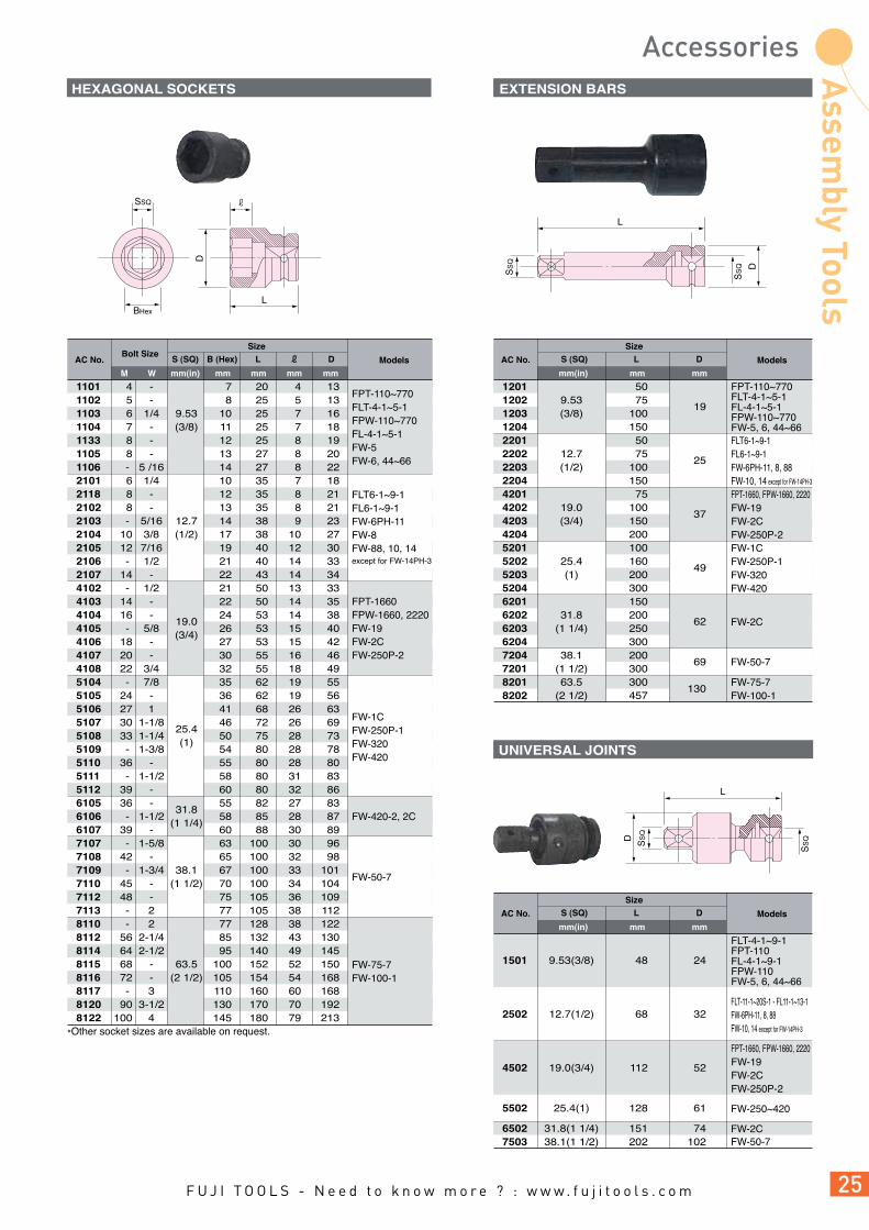
HEXAGONAL SOCKETS EXTENSION BARS
UNIVERSAL JOINTS
LBHex
SSQD
L
SS
Q
SS
Q D
L
SS
Q
SS
QD
1101 4 - 7 20 4 13 1102 5 - 8 25 5 13 1103 6 1/4 9.53 10 25 7 16 1104 7 - (3/8) 11 25 7 18 1133 8 - 12 25 8 19 1105 8 - 13 27 8 20 1106 - 5 /16 14 27 8 22 2101 6 1/4 10 35 7 18 2118 8 - 12 35 8 21 2102 8 - 13 35 8 21 2103 - 5/16 12.7 14 38 9 23 2104 10 3/8 (1/2) 17 38 10 27 2105 12 7/16 19 40 12 30 2106 - 1/2 21 40 14 33 2107 14 - 22 43 14 34 4102 - 1/2 21 50 13 33 4103 14 - 22 50 14 35 4104 16 -
19.0 24 53 14 38
4105 - 5/8 (3/4)
26 53 15 40 4106 18 - 27 53 15 42 4107 20 - 30 55 16 46 4108 22 3/4 32 55 18 49 5104 - 7/8 35 62 19 55 5105 24 - 36 62 19 56 5106 27 1 41 68 26 63 5107 30 1-1/8
25.4 46 72 26 69
5108 33 1-1/4 (1)
50 75 28 73 5109 - 1-3/8 54 80 28 78 5110 36 - 55 80 28 80 5111 - 1-1/2 58 80 31 83 5112 39 - 60 80 32 86 6105 36 -
31.8 55 82 27 83
6106 - 1-1/2 (1 1/4)
58 85 28 87 6107 39 - 60 88 30 89 7107 - 1-5/8 63 100 30 96 7108 42 - 65 100 32 98 7109 - 1-3/4 38.1 67 100 33 101 7110 45 - (1 1/2) 70 100 34 104 7112 48 - 75 105 36 109 7113 - 2 77 105 38 112 8110 - 2 77 128 38 122 8112 56 2-1/4 85 132 43 130 8114 64 2-1/2 95 140 49 145 8115 68 - 63.5 100 152 52 150 8116 72 - (2 1/2) 105 154 54 168 8117 - 3 110 160 60 168 8120 90 3-1/2 130 170 70 192 8122 100 4 145 180 79 213
AC No. Models
mm(in)M W mm mm mm mm
SizeBolt Size
S (SQ) B (Hex) L D
*Other socket sizes are available on request.
FPT-110~770FLT-4-1~5-1FPW-110~770FL-4-1~5-1FW-5FW-6, 44~66
FLT6-1~9-1FL6-1~9-1FW-6PH-11FW-8FW-88, 10, 14except for FW-14PH-3
FPT-1660FPW-1660, 2220FW-19FW-2CFW-250P-2
FW-1CFW-250P-1FW-320FW-420
FW-420-2, 2C
FW-50-7
FW-75-7FW-100-1
1201 50 1202 9.53 75
19 1203 (3/8) 100 1204 150 2201 50 2202 12.7 75
25 2203 (1/2) 100 2204 150 4201 75 4202 19.0 100
37 4203 (3/4) 150 4204 200 5201 100 5202 25.4 160
49 5203 (1) 200 5204 300 6201 150 6202 31.8 200
62 6203 (1 1/4) 250 6204 300 7204 38.1 200
69 7201 (1 1/2) 300 8201 63.5 300
130 8202 (2 1/2) 457
AC No. Models
mm(in) mm mm
SizeS (SQ) L D
FW-50-7
FW-75-7FW-100-1
FW-1CFW-250P-1FW-320FW-420
FW-2C
1501 9.53(3/8) 48 24
2502 12.7(1/2) 68 32
4502 19.0(3/4) 112 52
5502 25.4(1) 128 61 6502 31.8(1 1/4) 151 74 7503 38.1(1 1/2) 202 102
AC No. Models
mm(in) mm mm
SizeS (SQ) L D
FW-250~420
FW-2CFW-50-7
FPT-110~770FLT-4-1~5-1FL-4-1~5-1FPW-110~770FW-5, 6, 44~66FLT6-1~9-1FL6-1~9-1FW-6PH-11, 8, 88FW-10, 14 except for FW-14PH-3
FPT-1660, FPW-1660, 2220FW-19FW-2CFW-250P-2
FLT-4-1~9-1FPT-110FL-4-1~9-1FPW-110FW-5, 6, 44~66
FLT-11-1~20S-1 - FL11-1~13-1FW-6PH-11, 8, 88FW-10, 14 except for FW-14PH-3
FPT-1660, FPW-1660, 2220FW-19FW-2CFW-250P-2

Hardness AC No. Model Groupmm mm mm
Thickness Width Length
SLOTTED BITS
BITS SELECTION GUIDE
6.352513
t
ø7.2
W
6.350.8 25
75
9
ø6
1325 6.35
65
d
6.3525
9
d
6.3513
6.359
ø3.5
20
ø3.5
209.5
13
0.8 6 45 G A166045 (1) 0.8 6 70 G A166070 (1) 1.0 8 45 G A168045 (1) 1.0 8 70 G A168070 (1) 1.2 10 52 G A161052 (1) 1.2 10 70 G A161070 (1) 0.8 6 75 E B356075 (2)
Hardness AC No. Model Groupmm mm
DiameterPoint Size
Length
CROSS RECESSED BITS SINGLE-ENDED
3 1 65 H A161065 (1) 4.5 2 65 H A162065 (1) 7 1 50 H B351050 (2) 7 1 75 H B351075 (2) 4.5 1 100 H B351100 (2) 7 2 50 G B352050 (2) 7 2 75 G B352075 (2) 7 2 100 G B352100 (2) 7 2 150 G B352150 (2) 4.5 2 100 H B252100 (2) 7 3 75 E B353075 (2) 7 3 100 E B353100 (2) 7 3 150 G B353150 (2)
Hardness AC No. Model Groupmm mm
DiameterPoint Size
Length
CROSS RECESSED BITS DOUBLE-ENDED TORSION TYPE
3.5 2 65 H AT142065 (1) 3.5 2 110 H AT142110 (1) 3.5 2 75 H BT432075 (2) 3.5 2 100 H BT432100 (2)
Hardness AC No. Model Groupmm
Point SizeLength
CROSS RECESSED BITS DOUBLE-ENDED
1 45 H A141045 (1) 1 65 H A141065 (1) 1 110 H A141110 (1) 2 45 G A142045 (1) 2 65 G A142065 (1) 2 110 G A142110 (1) 2 150 G A142150 (1) 2 200 G A142200 (1) 2 300 G A142300 (1) 3 45 E A143045 (1) 3 65 E A143065 (1) 3 110 E A143110 (1) 1 75 H B431075 (2) 2 50 H B432050 (2) 2 75 G B432075 (2) 2 100 G B432100 (2) 2 150 G B432150 (2) 2 200 G B432200 (2) 3 75 E B433075 (2) 3 100 E B433100 (2)
FPT-110D-10, FLT-4D-1~4D-10~5D-1~5D-10~6D-1~6D10, 110SD-10, 330SD-10, 440SD-10, 550SD-10, 660SD-10
FPW-110D-10, 770D-30 - FL-4D-10~5D-10~6D-10, 110SD-10, 330SD-10, 440SD-10, 550SD-10, 660SD-10
FW-5SXD-70, 80, 6SXD-60, 5PXD-60, 6PMD-10, 6PLD-10, 6PXD-60, 6PHD-10, 44SAD-10, 66SAD-10, 44PAD-20, 66PAD-20
FPT-110D-1, FLT-4D-1~4D-10~5D-1~5D-10~6D-1~6D10, 110SD-1, 330SD-1, 440SD-1, 550SD-1, 660SD-1
FPW-110D-1, 770D-3 - FL-4D-1~5D-1~6D-1, 110SD-1, 330SD-1, 440SD-1, 550SD-1, 660SD-1
FW-5SXD-7, 8, 6SXD-6, 5PXD-6, 6PMD-1, 6PLD-1, 6PXD-6, 6PHD-1, 44SAD-1, 66SAD-1, 44PAD-2, 66PAD-2, FD-4, 5, 4P, 5P
(1)
GROUP MODELS
(2)
*Minimum order required : 100pcs. /item.
*Minimum order required : 100pcs. /item.
*Minimum order required : 100pcs. /item.
*Minimum order required : 100pcs. /item.
Fuji offers two types of screwdriver bits according to their neck length. Select suitable models or bits using the following table. Our screwdriver bits are available in three different categories of hardness to cover almost all applications: H (hard), G (standard), E (soft). The most common hardness bit are listed. Other hardness's are available on request.

ALLEN BITS
6.3513
H2•2.5•3•4•5•6
H2•2.5•3•4•5•66.35
259
ø7
Hardness AC No. Model Groupmm
Length
mm
Hex Size
2 65 H A16H2065 (1) 2 110 H A16H2110 (1) 2.5 65 H A16H25065 (1) 2.5 110 H A16H25110 (1) 3 65 H A16H3065 (1) 3 110 H A16H3110 (1) 4 65 H A16H4065 (1) 4 110 H A16H4110 (1) 5 65 G A16H5065 (1) 5 110 G A16H5110 (1) 6 65 G A16H6065 (1) 6 110 G A16H6110 (1) 2 75 H B35H2075 (2) 2 100 H B35H2100 (2) 2.5 75 H B35H25075 (2) 2.5 100 H B35H25100 (2) 3 75 H B35H3075 (2) 3 100 H B35H3100 (2) 4 75 H B35H4075 (2) 4 100 H B35H4100 (2) 5 75 G B35H5075 (2) 5 100 G B35H5100 (2) 6 75 G B35H6075 (2) 6 100 G B35H6100 (2)
TORX® BITS
Point Size AC No. Model Groupmm
Length
mm
Body Diameter
T6 65 4.0 VT6065 (1) T8 65 4.5 VT8065 (1) T8 110 4.5 VT8110 (1) T10 65 4.5 VT10065 (1) T10 110 4.5 VT10110 (1) T15 65 4.5 VT15065 (1) T15 110 4.5 VT15110 (1) T20 65 5.0 VT20065 (1) T20 110 5.0 VT20110 (1) T25 65 5.0 VT25065 (1) T25 110 5.0 VT25110 (1) T27 65 5.5 VT27065 (1) T27 110 5.5 VT27110 (1) T30 65 6.0 VT30065 (1) T30 110 6.0 VT30110 (1) T40 65 H6.35 VT40065 (1) T40 110 H6.35 VT40110 (1) T6 75 4.0 JT6075 (2) T6 100 4.0 JT6100 (2) T8 75 4.5 JT8075 (2) T8 100 4.5 JT8100 (2) T10 75 4.5 JT10075 (2) T10 100 4.5 JT10100 (2) T15 75 4.5 JT15075 (2) T15 100 4.5 JT15100 (2) T20 75 5.0 JT20075 (2) T20 100 5.0 JT20100 (2) T25 75 5.0 JT25075 (2) T25 100 5.0 JT25100 (2) T27 75 5.5 JT27075 (2) T27 100 5.5 JT27100 (2) T30 75 6.0 JT30075 (2) T30 100 6.0 JT30100 (2) T40 75 7.0 JT40075 (2) T40 100 7.0 JT40100 (2) T45 75 8.0 JT45075 (2) T45 100 8.0 JT45100 (2)
25
13
d
6.35
d
6.35
25
9
*TORX® is a registered trademark of Camcar Div., Textron Inc., USA.
*Minimum order required : 100pcs. /item.
*Minimum order required : 100pcs. /item.

L
S(S
Q)
BHex
DOUBLE-ENDED BIT
CHUCK
BHexL
S(S
Q)
D
ALLEN SOCKETS
CHUCKS FOR WRENCHES FOR USE OF BITS TOOL COVER FOR FPW SERIES
HG-3-4 4 50 15 19 HG-3-5
9.53 5 50 17 19
HG-3-6 (3/8)
6 50 18 19 HG-3-8 8 60 23 20 HG-3-10 10 60 27 20 HG-4-6 6 60 18 25 HG-4-8
12.7 8 60 23 25
HG-4-10 (1/2)
10 68 27 27 HG-4-12 12 68 30 27 HG-4-14 14 78 40 28
AC No. Models
mm(in) mm mm mm mm
SizeS (SQ) B (Hex) L D
DC-1 9.53(3/8) 6.35(1/4) 51
DC-2 12.7(1/4) 8.00(5/16) 56
AC No. Models
mm(in) mm mm
SizeS (SQ) B (Hex) L
TCV-1 FL-5-1~6-1 TCV-2 FL-7-1
AC No. Models
FPT-110~770FLT-4-1~9-1FL-4-1~9-1FPW-110~770FW-5,FW-6, 44~66
FLT-11-1~20S-1FL-11-1~13-1FW-6PH-11, 8, 88FW-10, 14 except for FW-14PH-3
FPT-110, FLT-4-1~9-1FPW-110, FL-4-1~9-1, FW-5, 6, 44~66FLT-11-1~20S-1 - FL11-1~13-1FW-6PH-11, 8, 88, 10, 14 except for FW-14PH-3
SOCKET HEAD BITS
AC No. Model Groupmm
Length
mm
Body Diameter
mm
Hex Size
4.5 55 7.5 A2045055 (1) 5 55 8.5 A205055 (1) 5.5 55 10 A2055055 (1) 5.5 100 10 A2055100 (1) 6 55 10 A206055 (1) 6 100 10 A206100 (1) 7 55 13 A207055 (1) 7 100 13 A207100 (1) 8 55 13 A208055 (1) 8 100 13 A208100 (1) 9 55 16 A209055 (1) 10 55 16 A2010055 (1) 10 100 16 A2010100 (1) 11 55 16 A2011055 (1) 12 55 19 A2012055 (1) 12 100 19 A2012100 (1) 13 55 19 A2013055 (1) 13 100 19 A2013100 (1) 14 55 20 A2014055 (1) 15 55 22 A2015055 (1) 17 55 23 A2017055 (1) 5.5 75 10 B4555075 (2) 5.5 100 10 B4555100 (2) 6 100 10 B456100 (2) 7 75 13 B457075 (2) 7 100 13 B457100 (2) 8 75 13 B458075 (2) 8 100 13 B458100 (2) 8 150 13 B458150 (2) 10 75 16 B4510075 (2) 10 100 16 B4510100 (2) 10 150 16 B4510150 (2) 12 100 18 B4512100 (2) 13 75 19 B4513075 (2) 13 100 19 B4513100 (2) 14 100 20 B4514100 (2)
25
33 2513
H5.5•6•7
Dø
6.35
ø7.2
2513
33
25
H8•10•136.35
H8•10•12•13•146.35
Dø
ø7.2
33
25
259
H5.5•6•76.35
Dø
ø7.2
33
25
259
20
2355
55
100
100
13
H4.5•5•5.5•6
Dø
ø7.2
6.35
23
20
13
H7•8•9•9.6•10•1112•13•14•15•17
Dø
ø7.2
6.35
*Minimum order required : 100pcs. /item.
ø7.2
Dø


1) INTENDED USEThe tool is designed to be used with abrasive product for grinding, cutting and sanding materials. Do not use the tool for any other purpose.
2) PROTECTIVE EQUIPMENTAlways wear necessary protective equipment such as an eye protector, an ear protector, a face shield, a safety apron, a helmet, gloves and other necessary protective clothing. Use protective barriers where necessary.
3) MAXIMUM SPEEDS OF ABRASIVEPRODUCT AND TOOL
Always check the spindle speed of the tool when mounting the abrasive product. Ensure that the maximum free speed rating of the abrasive product is above that of the tool in use.
4) WHEEL SIZES OF ABRASIVE PRODUCTAND PERIPHERAL SPEED
The following is a reference of Grinding wheel size / Peripheral speed / Maximum free speed. When using abrasive product, on which the peripheral speed is shown instead of the maximum allowable free speed, refer to the reference.
5) CORRECT WHEEL GUARD ANDFLANGES FOR GRINDER
Always use the wheel guard and wheel flanges supplied with the tool and ensure that they are mounted correctly with the appropriate tightness when mounting the abrasive product. Only trained & qualified personnel should mount the abrasive product. Do not use a wheel guard or the flanges if they are damaged or worn. Do not modify or repair a wheel guard or flanges.
6) CORRECT ABRASIVE PRODUCT TOCORRECT TOOL
Make sure the dimensions of the abrasive product are compatible with the tool and that the abrasive product fits the spindle of the tool.
7) MOUNTING AND DISMOUNTINGABRASIVE PRODUCT
When mounting and dismounting the abrasive product, make sure to disconnect tool. Make sure the dimensions of the abrasive product are compatible with the tool and that the abrasive product fits the spindle of the tool.
8) TOOL WITH SPEED GOVERNORFor the grinder with a speed governor, check the maximum free speed regularly. Make it a rule to check the maximum free speed, whenever before use.
INSTRUCTION AND WARNING FOR SAFETY USE
Grinding Peripheral speed (m/s) wheel diameter 10 15 20 25 28 30 33 35 40 45 48 50 60 70
25 40 50 63 80 100 115 125 150 180 200 230 250 300
mm Maximum free speed (min-1)
Wheel diameter / Peripheral speed / Maximum free speed
7639 11459 15279 19099 21390 22918 25210 26738 30558 34377 36669 38197 45837 53476 61115 4775 7162 9549 11937 13369 14324 15756 16711 19099 21486 22918 23873 28648 33423 38197 3820 5730 7639 9549 10695 11459 12605 13369 15279 17189 18335 19099 22918 26738 30558 3032 4547 6063 7579 8488 9095 10004 10610 12126 13642 14551 15158 18189 21221 24252 2387 3581 4775 5968 6685 7162 7878 8356 9549 10743 11459 11937 14324 16711 19099 1910 2865 3820 4775 5348 5730 6303 6685 7639 8594 9167 9549 11459 13369 15279 1661 2491 3321 4152 4650 4982 5480 5813 6643 7473 7972 8304 9964 11625 13286 1528 2292 3056 3820 4278 4584 5042 5348 6112 6875 7334 7639 9167 10695 12223 1273 1910 2546 3183 3565 3820 4202 4456 5093 5730 6112 6366 7639 8913 10186 1061 1592 2122 2653 2971 3183 3501 3714 4244 4775 5093 5305 6366 7427 8488 955 1432 1910 2387 2674 2865 3151 3342 3820 4297 4584 4775 5730 6685 7639 830 1246 1661 2076 2325 2491 2740 2906 3321 3737 3986 4152 4982 5813 6643 764 1146 1528 1910 2139 2292 2521 2674 3056 3438 3667 3820 4584 5348 6112 637 955 1273 1592 1783 1910 2101 2228 2546 2865 3056 3183 3820 4456 5093
80

2 CENTRIFUGAL SPEED GOVERNOR
3 ANTI-FREEZING SWIVEL SILENCER
4 GEAR COOLING DEVICE
6 ACCURATE COLLET ALIGNMENT
7 STURDY STEEL HOUSING
5 LOCKING LEVER HANDLE
The rear exhaust reduces the risk of scattering debris such as grindings, shavings, etc. due to the exhaust air direction. In addition, when using the inlet and exhaust hoses supplied with the tools, this helps to reduce the sound level.
FG-06-1, 13X, 12UX, 25DX, 26X, 50X, FA-2CX, 3CX SERIES
The speed governor maintains the working speed of the tool to a better degree than a conventional tool without a governor. Consequently, the abrasive life is improved due to the stability of the cutting speed. It is less susceptible to changes in air pressure and wear of the governor parts.
ANGLE, STRAIGHT, VERTICAL GRINDERS
The anti-freezing swivel silencer minimises the effect of freezing during operation of the tool. In addition, it also enables the operator to direct the exhaust air to provide maximum operator comfort.
ANGLE GRINDERS EXCEPT FA-2C, 3CX, 150K SERIES
The patented gear cooling device helps to minimise wearing of the bevel gear and pinion by metering some exhaust air through them and providing a cooling effect.
ANGLE GRINDERS
The locking lever helps to reduce the risk of inadvertent starting of the tool. The operator needs to push the locking lever, or the locking button, to start operation of the tool. When the lever is released, the tool automatically reverts to the locked condition.
The collet is mounted in the spindle in order to provide minimal deflection.Furthermore, the compact collet nut enables finishing operations in confined spaces.
DIE GRINDERS
Die Grinders feature a compact and durable steel housing for longer service life.
FG-13-2,13X-2, 20, 26-20
1 REAR EXHAUST
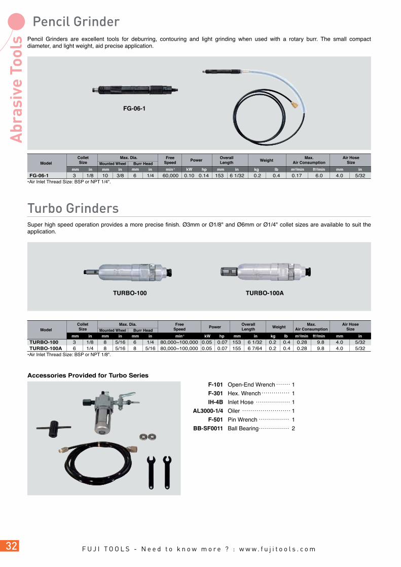
Pencil Grinders are excellent tools for deburring, contouring and light grinding when used with a rotary burr. The small compact diameter, and light weight, aid precise application.
FG-06-1 3 1/8 10 3/8 6 1/4 60,000 0.10 0.14 153 6 1/32 0.2 0.4 0.17 6.0 4.0 5/32
Model
m3/minkgmm in lb mmft3/min inmin-1mm in mm in in
Max. Dia. OverallLength
Air HoseSize
ColletSize
*Air Inlet Thread Size: BSP or NPT 1/4".
WeightMax.
Air ConsumptionFree
SpeedPower
FG-06-1
TURBO-100 3 1/8 8 5/16 6 1/4 80,000~100,000 0.05 0.07 153 6 1/32 0.2 0.4 0.28 9.8 4.0 5/32TURBO-100A 6 1/4 8 5/16 8 5/16 80,000~100,000 0.05 0.07 155 6 7/64 0.2 0.4 0.28 9.8 4.0 5/32
Model
mmin min-1 inkW hpmm
mm hpkW
mm in mm in
ColletSize
*Air Inlet Thread Size: BSP or NPT 1/8".
FreeSpeed
OverallLength
Max. Dia.
Mounted Wheel Burr Head
TURBO-100 TURBO-100A
Mounted Wheel Burr Head
m3/minkg lb mmft3/min in
Air HoseSizeWeightPower
Max.Air Consumption
Accessories Provided for Turbo Series
Open-End Wrench 1
Hex. Wrench 1
Inlet Hose 1
Oiler 1
Pin Wrench 1
Ball Bearing 2
F-101
F-301
IH-4B
AL3000-1/4
F-501
BB-SF0011
Super high speed operation provides a more precise finish. Ø3mm or Ø1/8" and Ø6mm or Ø1/4" collet sizes are available to suit the application.
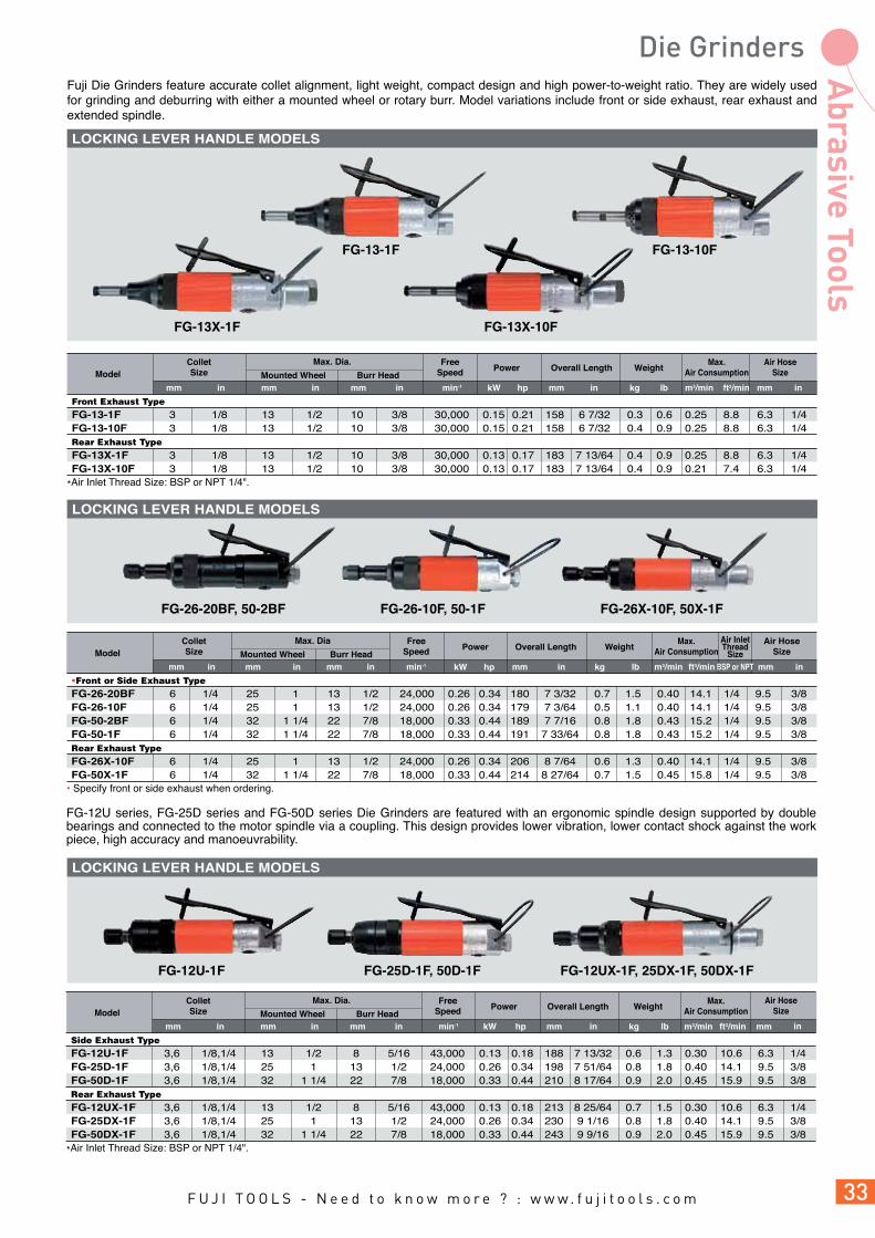
Fuji Die Grinders feature accurate collet alignment, light weight, compact design and high power-to-weight ratio. They are widely used for grinding and deburring with either a mounted wheel or rotary burr. Model variations include front or side exhaust, rear exhaust and extended spindle.
FG-13-1F FG-13-10F
FG-13X-1F FG-13X-10F
Front Exhaust TypeFG-13-1F 3 1/8 13 1/2 10 3/8 30,000 0.15 0.21 158 6 7/32 0.3 0.6 0.25 8.8 6.3 1/4FG-13-10F 3 1/8 13 1/2 10 3/8 30,000 0.15 0.21 158 6 7/32 0.4 0.9 0.25 8.8 6.3 1/4Rear Exhaust TypeFG-13X-1F 3 1/8 13 1/2 10 3/8 30,000 0.13 0.17 183 7 13/64 0.4 0.9 0.25 8.8 6.3 1/4FG-13X-10F 3 1/8 13 1/2 10 3/8 30,000 0.13 0.17 183 7 13/64 0.4 0.9 0.21 7.4 6.3 1/4
Model
kgmm mmkW hpmin-1 in m3/min mmlb ft3/minin inin mm in mm
ColletSize
Max. Dia. FreeSpeed
Air HoseSize
Max.Air ConsumptionMounted Wheel Burr Head
WeightOverall LengthPower
*Air Inlet Thread Size: BSP or NPT 1/4".
FG-26-10F, 50-1FFG-26-20BF, 50-2BF FG-26X-10F, 50X-1F
Front or Side Exhaust TypeFG-26-20BF 6 1/4 25 1 13 1/2 24,000 0.26 0.34 180 7 3/32 0.7 1.5 0.40 14.1 1/4 9.5FG-26-10F 6 1/4 25 1 13 1/2 24,000 0.26 0.34 179 7 3/64 0.5 1.1 0.40 14.1 1/4 9.5FG-50-2BF 6 1/4 32 1 1/4 22 7/8 18,000 0.33 0.44 189 7 7/16 0.8 1.8 0.43 15.2 1/4 9.5FG-50-1F 6 1/4 32 1 1/4 22 7/8 18,000 0.33 0.44 191 7 33/64 0.8 1.8 0.43 15.2 1/4 9.5Rear Exhaust TypeFG-26X-10F 6 1/4 25 1 13 1/2 24,000 0.26 0.34 206 8 7/64 0.6 1.3 0.40 14.1 1/4 9.5FG-50X-1F 6 1/4 32 1 1/4 22 7/8 18,000 0.33 0.44 214 8 27/64 0.7 1.5 0.45 15.8 1/4 9.5
Model
kgmm mmmin-1 in m3/min mmlb ft3/minin inin mm in mm
ColletSize
Max. Dia FreeSpeed
Air HoseSize
Air InletThread
Size
Max.Air ConsumptionMounted Wheel Burr Head
WeightPower Overall Length
3/83/83/83/8
3/83/8
• Specify front or side exhaust when ordering.
BSP or NPT
FG-12U series, FG-25D series and FG-50D series Die Grinders are featured with an ergonomic spindle design supported by double bearings and connected to the motor spindle via a coupling. This design provides lower vibration, lower contact shock against the work piece, high accuracy and manoeuvrability.
FG-12U-1F FG-25D-1F, 50D-1F FG-12UX-1F, 25DX-1F, 50DX-1F
Side Exhaust TypeFG-12U-1F 3,6 1/8,1/4 13 1/2 8 5/16 43,000 0.13 0.18 188 7 13/32 0.6 1.3 0.30 10.6 6.3 1/4FG-25D-1F 3,6 1/8,1/4 25 1 13 1/2 24,000 0.26 0.34 198 7 51/64 0.8 1.8 0.40 14.1 9.5 3/8FG-50D-1F 3,6 1/8,1/4 32 1 1/4 22 7/8 18,000 0.33 0.44 210 8 17/64 0.9 2.0 0.45 15.9 9.5 3/8Rear Exhaust TypeFG-12UX-1F 3,6 1/8,1/4 13 1/2 8 5/16 43,000 0.13 0.18 213 8 25/64 0.7 1.5 0.30 10.6 6.3 1/4FG-25DX-1F 3,6 1/8,1/4 25 1 13 1/2 24,000 0.26 0.34 230 9 1/16 0.8 1.8 0.40 14.1 9.5 3/8FG-50DX-1F 3,6 1/8,1/4 32 1 1/4 22 7/8 18,000 0.33 0.44 243 9 9/16 0.9 2.0 0.45 15.9 9.5 3/8
Model
kgmm mmmin-1 in m3/min mmlb ft3/minin inin mm in mm
ColletSize
Max. Dia. FreeSpeed
Air HoseSize
Max.Air ConsumptionMounted Wheel Burr Head
Weight
kW hp
Power Overall Length
*Air Inlet Thread Size: BSP or NPT 1/4".
kW hp
LOCKING LEVER HANDLE MODELS
LOCKING LEVER HANDLE MODELS
LOCKING LEVER HANDLE MODELS

FG-3H-5F
Locking Lever Handle ModelsFG-26L-1BF 6 1/4 25 x 13 x – 1 x 1/2 x – 24,000 5/16–24UNF 0.22 0.30 306 12 3/64 0.9 2.0 0.40 14.1 9.5 3/8FG-3H-5F 6 1/4 45 x 13 x – 1 25/32 x 1/2 x – 14,600 3/8-24UNF 0.48 0.64 367 14 29/64 1.5 3.3 0.55 19.4 9.5 3/8
Model
kgmm inmin-1 in mm m3/min mmlb ft3/min inin mm in
Max.Air Consumption
SpindleThread Size Air Hose SizeOverall Length Weight
kW hp
PowerCollet SizeFree
SpeedMax. Dia. (Mounted Wheel)
*Air Inlet Thread Size: BSP or NPT 1/4", FG-3H-5, 5F: BSP or NPT 3/8".
FG-26L-1BF
FA-2C-2BF, 3BF
FA-2CX-2BF, 3BF
Side Exhaust Type
Model
kgmm inmin-1 in mm m3/min mmlb ft3/min inin mm in
Max.Air Consumption
SpindleThread Size Air Hose SizeOverall Length Weight
kW hp
PowerCollet Size Max. Dia. (Mounted Wheel)
Locking Lever Handle ModelsFA-2C-2BF 6 1/4 38 x 13 x – 1 1/2 x 1/2 x – 15,000 3/8–24UNF(M) 0.26 0.34 188 7 13/32 0.7 1.5 0.40 14.1 9.5 3/8FA-2C-3BF 6 1/4 38 x 13 x – 1 1/2 x 1/2 x – 15,000 W3/8–16(M) 0.26 0.34 188 7 13/32 0.7 1.5 0.40 14.1 9.5 3/8
*Air Inlet Thread Size: BSP or NPT 1/4".
Rear Exhaust Type
Model
kgmm inmin-1 in mm m3/min mmlb ft3/min inin mm in
Max.Air Consumption
SpindleThread Size Air Hose SizeOverall Length Weight
kW hp
PowerCollet SizeFree
SpeedMax. Dia. (Mounted Wheel)
Locking Lever Handle ModelsFA-2CX-2BF 6 1/4 38 x 13 x – 1 1/2 x 1/2 x – 15,000 3/8–24UNF(M) 0.26 0.34 226 8 57/64 1.0 2.2 0.40 14.1 9.5 3/8FA-2CX-3BF 6 1/4 38 x 13 x – 1 1/2 x 1/2 x – 15,000 W3/8–16(M) 0.26 0.34 226 8 57/64 1.0 2.2 0.40 14.1 9.5 3/8
*Air Inlet Thread Size: BSP or NPT 1/4".
FreeSpeed
EXTENDED TYPE MODELS
ANGLE TYPE MODELS

These powerful Grinders are designed with a gear reduction mechanism and speed control governor to maintain the power and rotational speed. Their light weight and compact design make them excellent for polishing, grinding, paint removal and can be used with non-woven cloth, brushes, flap wheels and buffs.
FG-2VX-1F
FG-3VX-2F, 3F
FG-3VX-1F, 6F
Locking Lever Handle / Rear Exhaust ModelsFG-2VX-1F 6 1/4 4,300 3/8-24UNF 0.29 0.39 216 8 1/2 0.9 2.0 0.34 12.0 1/4 9.5 3/8FG-3VX-1F 6 1/4 7,600 W3/8-16 0.28 0.37 331 13 1/32 1.4 3.1 0.45 15.9 1/4 9.5 3/8FG-3VX-6F 6 1/4 12,000 W3/8-16 0.31 0.41 331 13 1/32 1.4 3.1 0.47 16.6 1/4 9.5 3/8
Model
kgmm mmmin-1 inin m3/min mmPT or NPTlb ft3/min inin
FreeSpeed
SpindleThread Size
Max.Air Consumption
Air InletThread SizeWeight
kW hp
Power Air Hose SizeOverall LengthCollet Size
Air InletThread SizeModel
kgmm inmin-1 inmm m3/min mmlb ft3/min inin
Max.Air Consumption
Weight(with wheel guard)
WheelThread Size Air Hose SizeOverall Length
hpkW
PowerCapacityFree
Speed
Locking lever Handle / Rear Exhaust ModelsFG-3VX-2F 75 x 19x 9.5 3 x 3/4 x 3/8 9,500 W3/8–16 0.29 0.39 316 12 7/16 • 1.4 • 3.1 0.47 16.6 1/4 9.5 3/8FG-3VX-3F 125 x 19x 9.5 5 x 3/4 x 3/8 7,600 W3/8–16 0.28 0.37 316 12 7/16 • 1.4 • 3.1 0.45 15.9 1/4 9.5 3/8
*Models marked • are without wheel guard.
BSP or NPT
Locking Lever Handle ModelsFG-3H-1F 65 x 13 x 9.53 2 1/2 x 1/2 x 3/8 14,600 W3/8–16 0.48 0.64 342 13 15/32 1.7 3.7 0.55 19.4 3/8 9.5 3/8FG-3H-2F 75 x 13 x 9.53 3 x 1/2 x 3/8 12,700 W3/8–16 0.48 0.64 342 13 15/32 1.7 3.7 0.55 19.4 3/8 9.5 3/8FG-4H-1F 100 x 19 x 9.53 4 x 3/4 x 3/8 9,500 W3/8–16 0.70 0.94 408 16 1/16 2.3 5.1 0.80 28.2 3/8 12.7 1/2FG-4H-2F 100 x 19 x 12.7 4 x 3/4 x 1/2 9,500 W1/2–12 0.70 0.94 414 16 19/64 2.3 5.1 0.80 28.2 3/8 12.7 1/2FG-5H-1M 125 x 19 x 12.7 5 x 3/4 x 1/2 7,600 W1/2–12 0.96 1.28 506 19 59/64 2.5 5.5 1.00 35.3 3/8 12.7 1/2FG-5H-2M 125 x 19 x 15.8 5 x 3/4 x 5/8 7,600 5/8–11UNF 0.96 1.28 511 20 7/64 2.5 5.5 1.00 35.3 3/8 12.7 1/2FG-6H-1M 150 x 25 x 15.8 6 x 1 x 5/8 6,300 5/8–11UNF 1.03 1.38 531 20 29/32 3.4 7.5 1.20 42.4 3/8 12.7 1/2FG-8H-1M 205 x 25 x 15.8 8 x 1 x 5/8 4,600 5/8–11UNF 1.47 1.97 556 21 57/64 5.5 12.1 1.60 56.5 1/2 12.7 1/2FG-8H-2M 180 x 25 x 15.8 7 x 1 x 5/8 5,300 5/8–11UNF 1.62 2.17 556 21 57/64 5.4 11.8 1.80 63.5 1/2 12.7 1/2Grip Handle ModelsFG-8H-1C 205 x 25 x 15.8 8 x 1 x 5/8 4,600 5/8–11UNF 1.47 1.97 538 21 3/16 5.6 12.3 1.60 56.5 3/8 12.7 1/2
Model
kgmm min-1 in inmm m3/min BSP or NPT mm inlb ft3/minin
FreeSpeed
SpindleThread Size
Max. AirConsumptionWeight
kW hp
PowerAir InletThread
SizeAir Hose SizeMax. Dia. (Grinding Wheel) Overall Length
FG-5H-1M, 2M, 6H-1MFG-3H-1F, 2F
FG-8H-1CFG-8H-1M, 2M
FG-4H-1F, 2F
All Fuji Grinders are designed and produced using Fuji's latest grinder technology. Fuji Straight Grinders are equipped with centrifugal speed control governors, noise reducing design, and a locking handle. These standard features assure high performance and smooth operation.

Fuji Extended Grinders are ideal for grinding operations in confined spaces or inside pipes. A wide range of Grinders is offered to cover various grinding operations.
Locking Lever Handle ModelsFG-50L-1BF 50 x 13 x 9.53 2 x 1/2 x 3/8 18,000 W3/8–16 0.29 0.39 316 12 7/16 1.4 3.1 0.43 15.2 9.5 3/8FG-50Y-1BF 50 x 13 x 9.53 2 x 1/2 x 3/8 18,000 W3/8–16 0.29 0.39 532 20 15/16 2.0 4.4 0.43 15.2 9.5 3/8FG-3HL-1F 65 x 13 x 9.53 2 1/2 x 1/2 x 3/8 12,000 W3/8–16 0.48 0.64 547 21 17/32 1.9 4.2 0.55 19.4 9.5 3/8FG-4HL-1F 75 x 19 x 9.53 3 x 3/4 x 3/8 12,000 W3/8–16 0.74 0.99 615 24 7/32 2.6 5.7 0.80 28.2 12.7 1/2FG-5HL-2M 100 x 19 x 12.7 4 x 3/4 x 1/2 9,000 W1/2–12 0.96 1.28 1,050 41 11/32 5.4 11.9 1.00 35.3 12.7 1/2
Model
kgmm min-1 inmm m3/min mm inlb ft3/minin
FreeSpeed
Max. AirConsumptionWeight
kW hp
Power Air Hose SizeMax. Dia. (Grinding Wheel) Overall Length
in
SpindleThread
Size
*FG-50L, 50Y series: 1/4" Air Inlet. FG-3HL, 4HL, 5HL series: 3/8" Air Inlet.
FG-50Y-1BF FG-4HL-1F
FG-50L-1BF FG-3HL-1F
Rear Exhaust TypeFA-2CX-1BF 50 x 4 x 9.5 2 x 5/32 x 3/8 15,000 1/4-28UNF(F) 47 1 55/64 0.26 0.34 226 8 57/64 1.0 2.2 0.40 14.1 9.5 3/8FA-3CX-1F 75 x 4 x 9.5 3 x 5/32 x 3/8 15,000 M8-1.25P(F) 63 2 31/64 0.33 0.44 247 9 3/4 1.3 2.9 0.40 14.1 9.5 3/8FA-3CX-2F 100 x 6 x 15.8 4 x 1/4 x 5/8 13,500 M8-1.25P(F) 63 2 31/64 0.33 0.44 247 9 3/4 1.3 2.9 0.40 14.1 9.5 3/8
FreeSpeed
FA-2CX-1BF
Model
kgmm min-1 inin mm inmm m3/min mm inlb ft3/minin
Max. Dia(Grinding Wheel)
Angle HeadHeight
SpindleThread Size
Max. AirConsumption
Air HoseSizeWeight
kW hp
Power Overall Length
Locking Lever Handle Models
*Air Inlet Thread SIze: BSP or NPT 1/4".
Max. Dia.(Grinding Wheel)
Angle HeadHeight
Air HoseSize
3/8-24UNF Thread Male Spindle TypeFA-5E-13F 125 x 6 x 22.2 5 x 1/4 x 7/8 12,000 75 2 61/64 0.96 1.29 282 11 7/64 2.2 4.8 0.95 33.5 9.5 3/8FA-5E-13VF 125 x 6 x 22.2 5 x 1/4 x 7/8 12,000 75 2 61/64 0.96 1.29 262 10 5/16 2.2 4.8 0.95 33.5 9.5 3/8
Model
kgmm min-1 in in inmm mm mmm3/minlb ft3/minin
Max. AirConsumptionOverall Length
FreeSpeed Weight
kW hp
Power
*Air Inlet Thread Size: BSP or NPT 3/8".
FA-5E-13F FA-5E-13VF
Locking Lever Handle Models
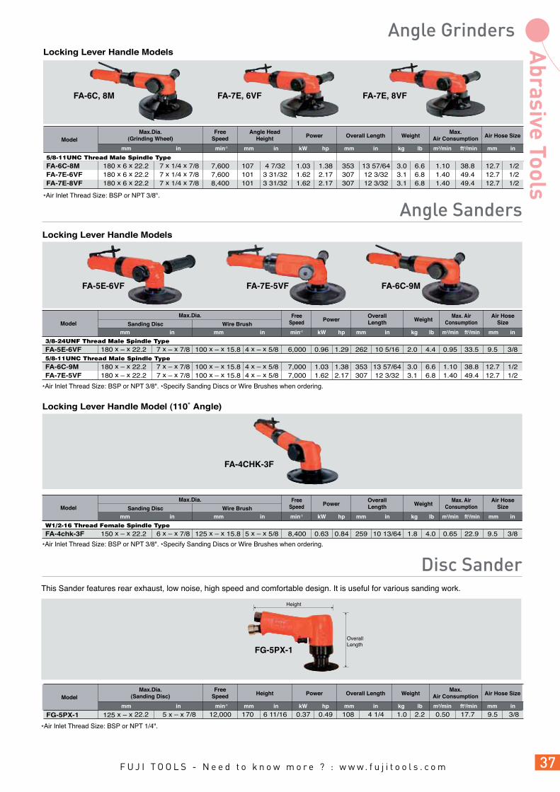
Fuji offers a wide variety of Angle Grinders for use in any grinding operation. Many models have features of machined bevel gears, speed control governor, built-in exhaust and a patented gear cooling design. Fuji has more models and variations than any other manufacturer.
FA-3CX-1F/2F
Locking Lever Handle Models
*Air Inlet Thread Size: BSP or NPT 3/8".
Model
mm in mmmin-1 in inmm m3/min mmin kW hp ft3/min
Weight Air Hose SizeOverall LengthFree
SpeedMax.Dia.
(Grinding Wheel)Max.
Air Consumption
lbkg
Angle HeadHeight Power
5/8-11UNC Thread Male Spindle TypeFA-6C-8M 180 x 6 x 22.2 7 x 1/4 x 7/8 7,600 107 4 7/32 1.03 1.38 353 13 57/64 3.0 6.6 1.10 38.8 12.7 1/2FA-7E-6VF 180 x 6 x 22.2 7 x 1/4 x 7/8 7,600 101 3 31/32 1.62 2.17 307 12 3/32 3.1 6.8 1.40 49.4 12.7 1/2FA-7E-8VF 180 x 6 x 22.2 7 x 1/4 x 7/8 8,400 101 3 31/32 1.62 2.17 307 12 3/32 3.1 6.8 1.40 49.4 12.7 1/2
Locking Lever Handle Models
FA-6C-9MFA-7E-5VF
*Air Inlet Thread Size: BSP or NPT 3/8". *Specify Sanding Discs or Wire Brushes when ordering.
Max.Dia.
Sanding Disc Wire BrushAir Hose
Size
3/8-24UNF Thread Male Spindle TypeFA-5E-6VF 180 x – x 22.2 7 x – x 7/8 100 x – x 15.8 4 x – x 5/8 6,000 0.96 1.29 262 10 5/16 2.0 4.4 0.95 33.5 9.5 3/85/8-11UNC Thread Male Spindle TypeFA-6C-9M 180 x – x 22.2 7 x – x 7/8 100 x – x 15.8 4 x – x 5/8 7,000 1.03 1.38 353 13 57/64 3.0 6.6 1.10 38.8 12.7 1/2FA-7E-5VF 180 x – x 22.2 7 x – x 7/8 100 x – x 15.8 4 x – x 5/8 7,000 1.62 2.17 307 12 3/32 3.1 6.8 1.40 49.4 12.7 1/2
Model
kgmm min-1in in inmm mm mmm3/minlb ft3/minin
Max. AirConsumption
OverallLengthPower
FreeSpeed Weight
kW hp
FA-5E-6VF
FA-4CHK-3F
Locking Lever Handle Model (110˚ Angle)
Max.Dia.
Sanding Disc Wire BrushAir Hose
Size
W1/2-16 Thread Female Spindle TypeFA-4chk-3F 150 x – x 22.2 6 x – x 7/8 125 x – x 15.8 5 x – x 5/8 8,400 0.63 0.84 259 10 13/64 1.8 4.0 0.65 22.9 9.5 3/8
Model
kgmm min-1in in inmm mm mmm3/minlb ft3/minin
Max. AirConsumption
OverallLengthPower
FreeSpeed Weight
kW hp
*Air Inlet Thread Size: BSP or NPT 3/8". *Specify Sanding Discs or Wire Brushes when ordering.
This Sander features rear exhaust, low noise, high speed and comfortable design. It is useful for various sanding work.
*Air Inlet Thread Size: BSP or NPT 1/4".
FG-5PX-1
OverallLength
Height
Model
mm in mmmin-1 in inmm m3/min mmin kW hp ft3/min
Weight Air Hose SizeOverall LengthFree
SpeedMax.Dia.
(Sanding Disc)Max.
Air Consumption
lbkg
Height Power
FG-5PX-1 125 x – x 22.2 5 x – x 7/8 12,000 170 6 11/16 0.37 0.49 108 4 1/4 1.0 2.2 0.50 17.7 9.5 3/8
FA-6C, 8M FA-7E, 6VF FA-7E, 8VF

Fuji Vertical Grinders are very powerful due to their direct drive shafts. All vertical grinders feature a centrifugal speed control governor that maintains rotational frequency even under a heavy grinding load. All Models are 5/8"-11UNC male spindle type with locking lever handle.
Height is a distance from wheel flange to top.Height
Overall Length
FV-9BH-1MFV-7-1M,4M
FV-9BH-4M
FV-7-2M
*Air Inlet Thread Size: BSP or NPT 3/8".
*Air Inlet Thread Size: BSP or NPT 1/2".
*Air Inlet Thread Size: BSP or NPT 3/8", FV-9BH Series: BSP or NPT 1/2".
FV-7-1M 180 x 6 x 22.2 7 x 1/4 x 7/8 6,000 192 7 9/16 1.40 1.87 247 9 23/32 4.0 8.8 1.40 49.4 12.7 1/2FV-7-4M 180 x 6 x 22.2 7 x 1/4 x 7/8 8,400 192 7 9/16 1.76 2.37 247 9 23/32 4.0 8.8 1.70 60.0 12.7 1/2FV-9BH-1M 230 x 10 x 22.2 9 x 3/8 x 7/8 5,900 222 8 47/64 2.90 3.88 278 10 61/64 5.8 12.7 2.80 98.9 19.0 3/4
Model
mm in mmmin-1 in inmm m3/min mmin kW hp ft3/min
Weight Air Hose SizeOverall LengthFree
SpeedMax.Dia.
(Grinding Wheel)Max.
Air Consumption
lbkg
Height Power
FV-9BH-4M 150 x 50 x 22.2 6 x 2 x 7/8 4,500 204 8 1/32 2.90 3.88 278 10 61/64 6.1 13.4 2.40 84.7 19.0 3/4
Model
mm in mmmin-1 in inmm m3/min mmin kW hp ft3/min
Weight Air Hose SizeOverall LengthFree
SpeedMax.Dia.
(Cup Wheel)Max.
Air Consumption
lbkg
Height Power
FV-7-2M 180 x – x 22.2 7 x – x 7/8 7,000 192 7 9/16 1.54 2.07 247 9 23/32 4.0 8.8 1.60 56.5 12.7 1/2
Model
mm in mmmin-1 in inmm m3/min mmin kW hp ft3/min
Weight Air Hose SizeOverall LengthFree
SpeedMax.Dia.
(Sanding Disc)Max.
Air Consumption
lbkg
Height Power
STANDARD TYPE
CUP WHEEL TYPE
SANDING DISC TYPE

Fuji Belt Sanders are ideal for precise and efficient sanding of confined areas such as spherical surfaces and tubes which are difficult to access with conventional grinders. They are also the ideal tool for de-burring applications. 360 degree head rotation provides versatile solution for almost any application.
FBS-1-1 10 x 330 13/32 x 12 1/64 20,000 1,200 0.28 0.37 281 11 5/64 124 4 57/64 1.1 2.4 0.57 20.1 9.5 3/8FBS-1-2 20 x 520 51/64 x 19 1/2 20,000 1,200 0.28 0.37 375 14 25/32 124 4 57/64 1.2 2.6 0.57 20.1 9.5 3/8FBS-1-3 13 x 460 33/64 x 18 1/8 20,000 1,200 0.28 0.37 345 13 19/32 124 4 57/64 1.2 2.6 0.57 20.1 9.5 3/8FBS-1-4 20 x 460 51/64 x 18 1/8 20,000 1,200 0.28 0.37 345 13 19/32 124 4 57/64 1.2 2.6 0.57 20.1 9.5 3/8
Model
kgmm in m3/min mmlb ft3/minmm inin min-1 m/min
BeltSpeed
FreeSpeed
Air HoseSize
Max. AirConsumptionWeightOverall LengthBelt Size
*Air Inlet Thread Size: BSP or NPT 1/4".
*Marked • are Standard Accessories.
inmm
Height
Corner Chamfering
Grinding of Welding BeadsFlat Sanding
Round Chamfering Flat Finishing
Inside Corner Sanding Chamfering of Small Pipe
Sanding in Narrow Space
FBS-1-2,4FBS-1-1,3
Angle Adjustment(Up to 360 degrees)
Sanding Belts
FBS-1-1 10 x 330 DSB-271 DSB-273 •DSB-274 DSB-275 DSB-276 FBS-1-2 20 x 520 DSB-261 DSB-263 •DSB-264 DSB-265 DSB-266 FBS-1-3 13 x 460 DSB-221 DSB-223 •DSB-224 DSB-225 DSB-226 FBS-1-4 20 x 460 DSB-241 DSB-243 •DSB-244 DSB-245 DSB-246
Grit#40
Belt Size(mm)
ApplicableModel
Grit#60
Grit#80
Grit#100
Grit#120
S-169044-00 10 x 330 FBS-1-1 S-169044-01 20 x 520 FBS-1-2 S-169044-02 13 x 460 FBS-1-3 S-169044-03 20 x 460 FBS-1-4
ModelSizeContact Arm Ass'y
Contact Arm Assembly
Guide Roller Spindle
Pad
Guide Roller
Needle RollerSpacer
Ball Bearing
Sanding Belts in different size are able to be mounted to the tool by replacing Contact Arm Ass'y.
kW hp
Power

Fuji Orbital Sanders are compact, lightweight & manoeuvrable, yet powerful enough for finishing lacquered and metal surfaces prior to re-painting. The effective dust extraction with rear exhaust helps to keep the working environment clean.
Capacity(Sanding Disc)
Angle HeadHeight
Power Air HoseSize
Locking Lever Handle ModelsFOR-125BF-E(M) ø125 5 8,000 124 4 7/8 0.118 0.158 243 9 9/16 2.0 4.4 0.36 12.7 6.3 1/4FOR-150BF-E(M) ø150 6 8,000 124 4 7/8 0.118 0.158 256 10 5/64 2.1 4.6 0.36 12.7 6.3 1/4
Model
kgmm min-1 in in inmm mm mmm3/minlb ft3/minin
Max. AirConsumptionOverall Length
FreeSpeed Weight
*Air Inlet Thread Size: BSP or NPT 1/4".*Adhesive paper type: (E). *Velcro paper type : (M).*FOR Series, Orbit 9mm (11/32")
Locking Lever Handle ModelsFOS-175BF-E(M) 100 x 175 4 x 7 6,500 130 5 1/8 0.118 0.158 268 10 9/16 2.4 5.2 0.34 11.9 6.3 1/4FOS-230BF-E 100 x 230 4 x 9 6,000 130 5 1/8 0.118 0.158 291 11 29/64 2.6 5.7 0.34 11.9 6.3 1/4FOS-400BF-E 100 x 400 4 x 16 5,500 130 5 1/8 0.118 0.158 400 16 3.3 7.2 0.32 11.3 6.3 1/4
Model
*Air Inlet Thread Size: BSP or NPT 1/4".*Adhesive paper type: (E). *Velcro paper type : (M).*FOS Series, Orbit 5mm (3/16")
FOS-175BF
FOR-125BF, 150BF
FeaturesPowerful sanding, high stability and low vibration.Excellent dust extraction ability to help keep the work area cleanAvailable to suit variations of sandpapers; self-adhesive type, Velcro (Nylon Strip Fastener) Type and standard Clip-on Type.
kW hp
Capacity(Sanding Pad Size)
Angle HeadHeight
Power Air HoseSize
kgmm min-1 in in inmm mm mmm3/minlb ft3/minin
Max. AirConsumptionOverall Length
FreeSpeed Weight
kW hp
DISC TYPE
RECTANGLE SHEET TYPE

43
34
55
36
175
100
29
3
27 4617
FOS-175 Series
224
95
35.5 ø9
321520
FOS-230 Series
400
100
35.5
321822 39 43
FOS-400 Series
FOR-125 Series FOR-150 Series
ø124 ø150Disc Type
Rectangle Sheet Type
FOR-125B • • • Rod • 2pcs. FOR-150B • • • Rod • 2pcs. FOS-175BF • • - - • 2pcs. FOS-230BF-E • • - • • 2pcs. FOS-400BF-E • • - • • 2pcs.
PunchingTool / Rod
Model Dust Bag Spanner Sanding DiscExhaust Hose
* • = provided, - = not provided
FOR-125 FOR-125-#40~#150 PAD-125E FOR-125-M40~M600 PAD-125M FOR-150 FOR-150-#40~#150 PAD-150E FOR-150-M40~M600 PAD-150M
Model
* Specify the grit when ordering sanding papers.
- - FOS-175 FOS-175-#40~#240 PAD-175E FOS-175-M40~M600 PAD-175M - FOS-230 FOS-230-#40~#240 PAD-230E - - FOS-230-C40~C240 FOS-400 FOS-400-#40~#240 PAD-400E - - FOS-400-C40~C240
ModelAdhesive Paper Type
Paper Pad Paper Pad
Velcro Paper Type
Adhesive Paper Type
Paper Pad Paper Pad
Velcro Paper Type
Roll Paper (Clip-on type)
* Roll Paper Size: 100mm x 15m (Dimension: FOS-230 (100 x 300)mm, FOS-400 (100 x 470) mm). * Specify the grit when ordering sanding papers.
ACCESSORIES PROVIDED
HOLE PATTERN AND DIMENSIONS OF SANDING PAPERS AND PADS

AC No. Collet Collet Nut
Size
LDd2dd1
Models
mm mm mminin mmmm
G-001342-01 3.0 - 1/4-28UNF 3/10 20 TURBO-100
G-001342-02 - 1/8 G-002342-00 6.0 -
W11-24 2/5 23 TURBO-100A G-002342-01 - 1/4 G-185342-00 3.0 -
1/4-28UNF - 18 FG-06-1
G-185342-01 - 1/8 FG-13Series, 13XSeries
Parts No.
Size
LD Taper
d Models
mm in mm
CONE WHEEL APPLICATIONS
CONE WHEEL
d D
L
L
L
D d d1 d2
G-013308-00 9.53 3/8 20 13.5
Part No.
Size
Ld D
mm in mmmm
124 38 65 W3/8-16 A-36P
AC No.
Size
Ld
D Material
mm mm
G-028342-08 3.0 - FG-12U, 12UX
G-028342-04 - 1/8 FG-25D, 25DX
G-028342-07 6.0 - FG-50D, 50DX
G-028342-06 - 1/4
Parts No.
Size
d Models
mm in
G-032347-00 6.0 - 3.0 - FG-26, 26X, 26L, 50, 50L, 50Y Series G-032347-02 6.0 - - 1/8 FG-3H, 3HL, 4H, 4HL Series G-032347-03 - 1/4 - 1/8 FA-2C, 2BF, 3BF, 2CX,2BF, 3BF
Parts No. Models
Size
D d
mm in mm in
G-158309-00 W3/8-16 5/16-24UNF
Part No.
Size
D d
dD
L
d
d
D
L
d D
L
D d d1 d2
39
D
ADAPTER
SPACER
FG-26, 50 Series
FG-50L, 50Y SeriesFG-3H, 3HL Series
d ø8
25
d D
26
*These collet bushes are used for collet chucks.
FG-50L-, 1BF, 50Y-, 1BF, 3HL-, 1F, 4HL-1F, 4H-1F
CN-1210 G-101342-00 6 - 3/8-24UNF
- 3/8 17Hex 57 32
FG-50L, 2BF, 50Y, 2BF, 3HL, 2F,
CN-1207 G-041342-00 - 1/4 CN-1402 G-017342-00 6 -
W3/8-16
- 3/8 17Hex 57 32
CN-1404 G-017342-01 G-162343-00
- 1/4 CN-1202 G-011342-00 6 -
3/8-24UNF
- 3/8 17Hex 42 17 FG-2VX-1F,
CN-1208 G-028342-00 - 1/4 FA-2C, 2BF, 2CX, 2BF CN-1406 A-122342-01 6 -
W3/8-16 - 3/8 17Hex 42 17
FA-2C, 3BF, 2CX, 3BF CN-1407 A-122342-02 - 1/4 CN-1114 G-144342-03
G-144343-02 3 -
14 44 21 CN-1115 G-144342-04 - 1/8
5/16-24UNF
12
- FG-26, 26X, 26L,
CN-1112 G-144342-00 G-144343-00
6 - 16 44 21
FG-50, 50X Series CN-1113 G-144342-01 - 1/4
COLLET BUSHES
COLLET CHUCKS
COLLETS
CONE WHEEL
ADAPTER FOR CONE WHEEL
SPACER FOR CONE WHEEL
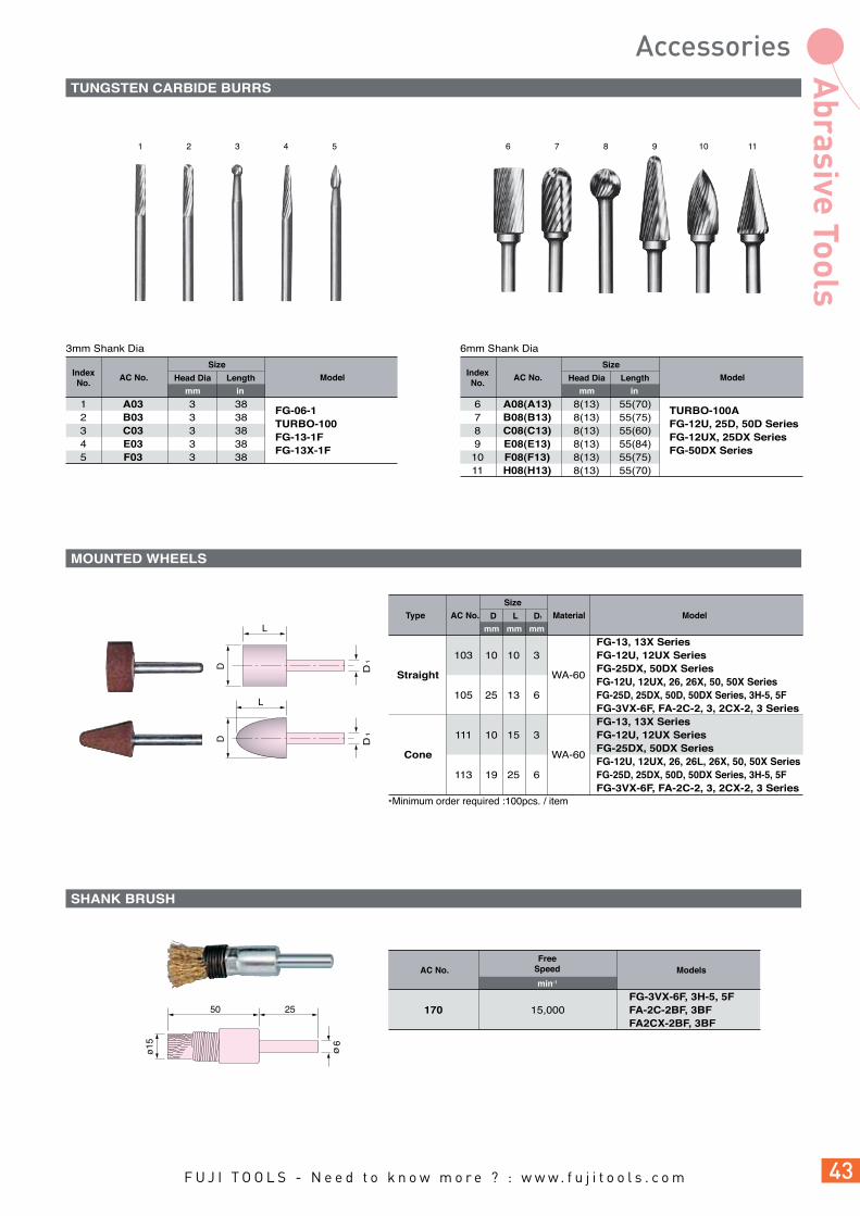
ø15 ø6
50 25
3mm Shank Dia
FG-3VX-6F, 3H-5, 5F170 15,000 FA-2C-2BF, 3BF FA2CX-2BF, 3BF
AC No. Models
FG-13, 13X Series 103 10 10 3 FG-12U, 12UX Series
Straight
WA-60 FG-25DX, 50DX Series
FG-12U, 12UX, 26, 26X, 50, 50X Series 105 25 13 6 FG-25D, 25DX, 50D, 50DX Series, 3H-5, 5F FG-3VX-6F, FA-2C-2, 3, 2CX-2, 3 Series FG-13, 13X Series 111 10 15 3 FG-12U, 12UX Series
Cone
WA-60 FG-25DX, 50DX Series
FG-12U, 12UX, 26, 26L, 26X, 50, 50X Series 113 19 25 6 FG-25D, 25DX, 50D, 50DX Series, 3H-5, 5F FG-3VX-6F, FA-2C-2, 3, 2CX-2, 3 Series
Type AC No.
Size
L D1D ModelMaterial
mm mm mm
1 A03 3 38 FG-06-1
2 B03 3 38 TURBO-100
3 C03 3 38 FG-13-1F
4 E03 3 38 FG-13X-1F
5 F03 3 38
AC No.IndexNo.
1 6 7 8 9 10 112 3 4 5
Size
LengthHead Dia Model
mm in
6mm Shank Dia
6 A08(A13) 8(13) 55(70) TURBO-100A
7 B08(B13) 8(13) 55(75) FG-12U, 25D, 50D Series
8 C08(C13) 8(13) 55(60) FG-12UX, 25DX Series
9 E08(E13) 8(13) 55(84) FG-50DX Series
10 F08(F13) 8(13) 55(75)
11 H08(H13) 8(13) 55(70)
AC No.IndexNo.
Size
LengthHead Dia Model
mm in
min-1
FreeSpeed
D1
D1
L
L
DD
*Minimum order required :100pcs. / item
TUNGSTEN CARBIDE BURRS
MOUNTED WHEELS
SHANK BRUSH

48
in
d D
d D
AC No. Models
Size Maximum FreeSpeedt dD
mm mmmm min-1
KWH-100WK5 100 13 10 12,000 FG-4H-1F KWH-123WK5 125 14 16 9,500 FG-5H KWH-156WK5 150 17 16 7,500 FG-6H-1M
t
t
AC No. ModelsSize Maximum Free
Speedt dD
mm mmmm min-1
181 50 13 10 18,000 182 65 13 10 15,000 FG-3H-1F, 3HL-1F 183 75 13 10 13,000 FG-3H-2F, 4HL-1F 184 100 13 10 9,500 FG-4H-1F 184-2 100 13 13 9,500 FG-4H-2F, 5HL-2M 185 125 19 16 7,600 FG-5H-2M 185-2 125 19 13 7,600 FG-5H-1M 186 150 25 16 6,300 FG-6H-1M 187 205 25 16 4,600 FG-8H-1C, 1M
*Minimum order required :10pcs. / item.
*Minimum order required :10pcs. / item.
d
t
D
Maximum FreeSpeedAC No. Models
Size
t dD Material
mm in in inmmmm min-1
•131 50 2 13 1/2 9.53 3/8 A-36Q 18,000 •132 65 2 1/2 13 1/2 9.53 3/8 A-30R 14,000 FG-3H-1F, 3HL-1F, 2F •133 75 3 13 1/2 9.53 3/8 A-24P 12,000 FG-3H-2F, 4HL-1F •133-1 75 3 19 3/4 9.53 3/8 A-24P 12,000 FG-4HL-1F 134 100 4 19 3/4 9.53 3/8 A-24P 9,000 FG-4H-1F 136-2 125 5 19 3/4 12.70 1/2 A-24P 7,600 FG-5H-1M 137 125 5 19 3/4 15.88 5/8 A-24P 7,600 FG-5H-2M 138 150 6 25 1 15.88 5/8 A-24P 6,300 FG-6H-1M 139 180 7 25 1 15.88 5/8 A-24P 5,300 FG-8H-2 Series
140 205 8 25 1 15.88 5/8 A-24P 4,600 FG-8H-1 Series
Comfort grip to soften application vibration
and warm to touch.
Tube diameter will shrink to half size when
heated to 120ºC (250ºF).
Cut to suitable size to fit the tool.
AC No. ModelsLengthBefore After Object
SizeInside Diameter Thickness
mmmmmm
Inside Diameter
mmm
M20-10-1 5 20 10 1 12~17 FG-06
M20-10-2 5 20 10 2 12~17 M30-15-1 5 30 15 1 18~27
FG-26L M30-15-2 5 30 15 2 18~27 M40-20-1 5 40 20 1 23~35
FG-50, 3HL M40-20-2 5 40 20 2 23~35 M50-25-2 5 50 25 2 28~45
FG-4HL M50-25-3 5 50 25 3 28~45 M60-30-2 5 60 30 2 35~55
FG-5HL M60-30-3 5 60 30 3 35~55
* • = Minimum order required :100pcs. / item, others = Minimum order required : 50pcs. / item.
RADIAL WIRE BRUSHES
STRAIGHT GRINDING WHEELS FOR STRAIGHT AND EXTENSION GRINDERS
HEAT SHRINK-TUBES FOR EXTENSION GRINDERS

65
ADHESIVE TYPE
Fig 1.
Fig 1.
Fig 8.Fig 8.
Fig 2.
Fig 2.
Fig 3. Fig 4.
Fig 6.
Fig 7.
Fig 4.
Fig 6.
Fig 7.
Fig 4.
Fig 5.
Fig 6.
Fig 7.
Fig 3.
45ø
22.7 14
40
29.5
14
14
19 5
10 5
10 5
DD
W3/
8-16
6ø
1/4-
28U
NF
d
45ø
21
14
14
W3/
8-16
RP-2-1 W3/8-24 RP-2-2 W3/8-16
AC No.Size
d
A-122693-00 W3/8-24 FA-2C-1BF A-122693-01 W3/8-16 FA-2CX-1BF
Parts No. ModelsSize
D
A-122693-03 W3/8-16 FA-2CX-2, 3 Series
Parts No. Models
Models
Size
D
A-122308-01 FA-2C-3BF, 2CX-3BF
Part No.
MP-2-1
AC No.
VELCRO TYPE
MP-2-1S
AC No.
VELCRO WITH SPONGE TYPE
50ø
32
W3/
8-16
ACCESSORIES FOR FA-2C, -2CX SERIES
ATTACHMENTS
SPACER
RUBBER BACKING PADS Fig 4.
Fig. 4
Fig. 4
Fig. 4

Fig 5.
Fig 8.
Fig 6.
Fig 7.
AC No.
Size
H dD Grit # Models
mm mmmm
D
d
D
d
D
Dd
H MC-2-16 40 18 W3/8-16 60 FA-2C-2BF, 2CX, 3BF
MD-1 40 MD-2
1/4-28 60
FA-2C-1BF MD-3 50
UNF 80
FA-2CX-1BF MD-4 100 MD-5 120
AC No.
Size
dD ModelsGrit #
mm mm
*Minimum order required : 50pcs. / item
DP-2-1 40 DP-2-2 60 DP-2-3 80 DP-2-4 100
DP-2-5
50 16 120
FA-2CX-2, 3 DP-2-6 150
Series DP-2-7 180 DP-2-8 240 DP-2-9 320 DP-2-10
400
AC No.
Size
dD ModelsGrit #
mm mm
*Minimum order required :100pcs. / item
MP-2-10 40 MP-2-2 60 MP-2-3 80
MP-2-4
50 100
FA-2CX-2, 3 MP-2-5
120
Series MP-2-6 150 MP-2-7 240 MP-2-8 320
AC No.
Size
D ModelsGrit #
mm
*Minimum order required :100pcs. / item
*Minimum order required :10pcs. / item
SHAFT TYPE
ADHESIVE TYPE
VELCRO TYPE
SANDING DISCS
CUP WHEEL

AC No. Models
Size MaximumFree
Speedt dD Pin Space
mm in in inmmmm inmm
d
D
t
min-1
d
D
FP-3-1 75 3 22.2 7/8 FG-5PX-1
FP-5-1 125 5 22.2 7/8
AC No.
Size
dD Model
mm in inmm
RP-2-1 45 1 49/64 22.7 57/64 - 3/8-24UNF 15,000 FA-2C-1BF, 1BF *(A-122693-00) RP-2-2 45 1 49/64 22.7 57/64 - W3/8-16 15,000 FA-2C-1BF, 2CX-1BF *(A-122693-01) RP-4-3 100 4 12.0 15/32 15.8 5/8 34 1 11/32 13,500 FA3CX-2F RP-5-5 125 5 17.0 43/64 22.2 7/8 46 1 13/16 8,500 FA-4CHK-3 RP-5-6 125 5 14.0 35/64 22.2 7/8 46 1 13/16 8,500 FA-5E-4 Series RP-7 180 7 15.0 19/32 22.2 7/8 46 1 13/16 7,000 FA-5E-6 Series, 7E-1, 5 Series, FV-7-1M, 2M RP-9-1 230 9 15.0 19/32 22.2 7/8 46 1 13/16 5,900 FV-9BH-1M
with Attachments
"
*Marked * are attachment number.
WIRE BRUSHWIRE BRUSH
SANDING DISCWITH RUBBER PAD
MALE SPINDLE5/8-11UNC THREAD
FEMALE SPINDLEW1/2-16 THREAD
SANDING DISCWITH RUBBER PAD
A
A
B C D
*Male Spindle 3/8-24UNF Thread type is applicable to type
RUBBER PAD AND WIRE BRUSH COMBINATION FOR ANGLE SANDERS
RUBBER BACKING PADS FOR ANGLE AND VERTICAL SANDERS
DISC BACKING PADS FOR FG-5PX-1
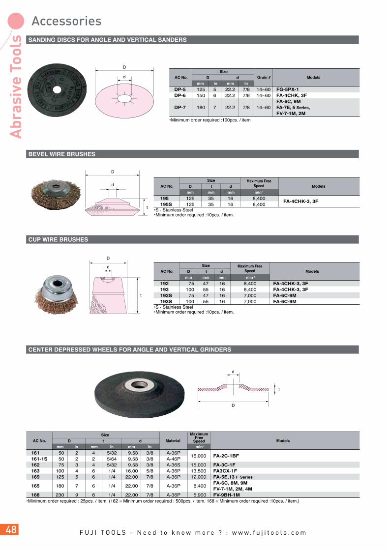
DP-5 125 5 22.2 7/8 14~60 FG-5PX-1 DP-6 150 6 22.2 7/8 14~60 FA-4CHK, 3F FA-6C, 9M DP-7 180 7 22.2 7/8 14~60 FA-7E, 5 Series, FV-7-1M, 2M
AC No.
Size
dD Models
mm in inmm
D
d Grain #
*Minimum order required :100pcs. / item
d
t
D
AC No. ModelsSize Maximum
FreeSpeedt dD Material
mm in in inmmmm min-1
161 50 2 4 5/32 9.53 3/8 A-36P 15,000 FA-2C-1BF
161-1S 50 2 2 5/64 9.53 3/8 A-46P 162 75 3 4 5/32 9.53 3/8 A-36S 15,000 FA-3C-1F 163 100 4 6 1/4 16.00 5/8 A-36P 13,500 FA3CX-1F 169 125 5 6 1/4 22.00 7/8 A-36P 12,000 FA-5E,13 F Series
165 180 7 6 1/4 22.00 7/8 A-36P 8,400
FA-6C, 8M, 9M FV-7-1M, 2M, 4M 168 230 9 6 1/4 22.00 7/8 A-36P 5,900 FV-9BH-1M
*Minimum order required : 25pcs. / item. (162 = Minimum order required : 500pcs. / item, 168 = Minimum order required :10pcs. / item.)
AC No. Models
Size Maximum FreeSpeedt dD
mm mmmm
d
D
t
d
D
min-1
195 125 35 16 8,400 FA-4CHK-3, 3F
195S 125 35 16 8,400
AC No. Models
Size Maximum FreeSpeedt dD
mm mmmm min-1
192 75 47 16 8,400 FA-4CHK-3, 3F 193 100 55 16 8,400 FA-4CHK-3, 3F 192S 75 47 16 7,000 FA-6C-9M 193S 100 55 16 7,000 FA-6C-9M
t
*S - Stainless Steel*Minimum order required :10pcs. / item.
*S - Stainless Steel*Minimum order required :10pcs. / item.
SANDING DISCS FOR ANGLE AND VERTICAL SANDERS
BEVEL WIRE BRUSHES
CUP WIRE BRUSHES
CENTER DEPRESSED WHEELS FOR ANGLE AND VERTICAL GRINDERS


9-12 12-15 24-33 30-45 24-27 60-90 60-90 75-120 30-45 90-120 15-18
3mm 1100 1400 3000 4000 2700 8000 8000 10400 4000 11000 1750
4mm 840 1100 2200 3000 2000 6000 6000 7800 3000 8400 1300
5mm 660 860 1800 2400 1600 4800 4800 6200 2400 6700 1050
6mm 550 700 1500 2000 1350 4000 4000 5200 2000 5600 880
8mm 420 540 1100 1500 1000 3000 3000 3900 1500 4200 660
10mm 330 430 900 1200 800 2400 2400 3100 1200 3300 630
12mm 280 350 750 1000 700 2000 2000 2600 1000 2800 440
13mm 260 330 700 920 630 1800 1800 2400 920 2550 400
14mm 240 300 640 850 580 1700 1700 2200 850 2400 370
16mm 210 270 560 750 500 1500 1500 1950 750 2100 330
19mm 180 230 480 630 430 1250 1250 1600 630 1800 280
22mm 150 200 410 540 370 1100 1100 1400 540 1500 240
23mm 140 190 390 520 350 1000 1000 1350 520 1450 230
25mm 130 170 360 480 320 960 960 1250 480 1330 210
28mm 120 150 320 420 290 850 850 1100 420 1200 190
32mm 100 130 280 380 250 750 750 980 380 1050 160
44mm 75 100 210 270 180 550 550 700 270 750 120
50mm 65 85 180 240 160 480 480 620 240 670 110
75mm 44 57 120 160 110 320 320 420 160 450 70
100mm 33 43 90 120 80 240 240 310 120 330 55
When selecting a suitable model of drill for your application, it should be chosen on the basis of drill bit size and suitable cutting speed for the material to be drilled. The table below shows the recommended drill bit sizes for different speeds when drilling some common materials. The figures in the table are based on drill speeds at normal pressure and the minimum torque in conjunction with drill breakthrough. The table only shows which drill bit sizes give the cutting speeds within the ranges stated. Note that it is quite possible to drill with smaller diameter drill bits, i.e. at lower cutting speeds. Longer drill bits than those indicated may also be used for occasional drilling work. However, in the case of drill bit sizes larger than the standard chuck capacity of the machine, the torque may be insufficient for the high cutting forces occurring in conjunction with drill breakthrough.In order to obtain a sufficient cutting force when applying feed pressure by hand, pre-drilling is recommended for drill bit sizes above 8 mm when drilling in mild steel, soft cast iron, malleable iron as well as for holes larger than 6 mm in forged steel and stainless steel.
Soft CastIron
Suggested Cutting Speed (min-1) for Drilling
Titanium
Drill bit size
Cutting speed(m/min)
Material StainlessSteel
ForgedSteel
Mild Steel MalleableIron
Brass orBronze
Aluminum Magnesium Plastic Wood
DRILL SIZE, CUTTING SPEED AND MATERIAL

Fuji offer some reversible drills. The reverse action is selected by simply turning the reverse lever.
FRD-20R~100R, FCD-23R~100R, F-22RCR, 32RCR
This mechanism allows slow start smooth operation to full speed allowing the drill bit to be centralised prior to drilling at full speed.
FRD-5P, 8PX, 12Z~16Z
The locking handle is designed to reduce the risk of inadvertent starting of the drill. The handle reverts automatically to the locked position when released.
The plastic cover softens the effect of vibration during the drilling application and creates a "warm to touch" feeling to improve operator comfort.
FCD-10X, 6EX
The dead handle helps to soften the breakthrough reaction force experienced when drilling "through holes".
FRD-6S-7, 6PX-7, 8PX-2, 3, 12Z~16Z
When the operator releases the handle, it automatically returns to the "OFF" position and the air supply is switched off. When ordering, add "S" to the end of the model name.
FRD-20R~100R, FCD-23R~100R
Connecting an air exhaust hose, with the optional swivel type air exhaust hose joint, provides improved operator comfort by directing the exhaust air away and reducing the noise level.
FRD-20R~50R, FCD-23R~100R
The exhaust cover can be rotated to enable the operator to choose a convenient direction of the exhaust air.
FRD-20R~50R, FCD-23R~100R
The noise level is minimised via the muffler built into the exhaust cover.
FRD-5P, 6PX, 8PX, FCD-6X, 10X
1 REVERSIBLE DRILLS
2 TWO-STAGE THROTTLE ACTUATION
3 SWIVEL TYPE EXHAUST COVER
4 REAR EXHAUST WITH BUILT-IN MUFFLER
5 LOCKING HANDLE
6 PLASTIC COVER
7 DEAD HANDLE
8 SELF-RETURN ROLL HANDLE
9 SWIVEL TYPE AIR EXHAUST HOSE JOINT (OPTION)

Fuji Drills are light weight with a sturdy construction. Their practical design represents Fuji's latest developments in drills technology.Fuji offers a complete line of drills with a drilling capacity range from 2mm to 100mm.
*FRD-5 series: 1/4" Air Inlet, 1/4"(6.35mm) Air Hose. All other models: 1/4" Air Inlet, 3/8"(9.5mm) Air Hose.*Marked • are furnished with Dead Handle.
FRD-5S-1F – 5 3/16 2.0 0.20 1.4 3,200 3/8–24 – 6.5 – 18.5 47/64 0.18 0.24 175 6 57/64 0.6 1.3 0.60 21.2 – FRD-5S-2TF 2 5/64 0.3 0.03 0.2 24,000 – J.T#D – 5.0 18.5 47/64 0.18 0.24 164 6 15/32 0.6 1.3 0.60 21.2FRD-6S-2F – 5 3/16 2.5 0.25 1.8 4,300 3/8–24 – 6.5 – 21.0 53/64 0.29 0.39 209 8 15/64 0.9 1.9 0.68 24.0FRD-6S-3F – 8 5/16 2.9 0.30 2.1 2,800 3/8–24 – 8.0 – 21.0 53/64 0.29 0.39 212 8 23/64 1.0 2.2 0.68 24.0FRD-6S-5F – 10 7/16 6.9 0.70 5.0 1,300 3/8–24 – 10.0 – 23.0 29/32 0.29 0.39 233 9 3/16 1.0 2.2 0.68 24.0
•FRD-6S-7F – 13 1/2 15.7 1.60 11.5 600 1/2–20 – 13.0 – 21.0 53/64 0.29 0.39 261 10 9/32 1.5 3.3 0.68 24.0
kgmm N•m kgf•m ft•lbThread Type Taper Type min-1 in inThread Taper Thread Taper mm kW hp mm m3/minlb ft3/minin
DrillingCapacity
Max. AirConsumptionOverall LengthSide to Center Power
ChuckCapacity
(mm)Stall TorqueModel
FreeSpeed
Type and Size of Spindle Weight
*FRD-5 series: 1/4" Air Inlet, 1/4"(6.35mm) Air Hose. All other models: 1/4" Air Inlet, 3/8"(9.5mm) Air Hose.*Marked • are furnished with Dead Handle.
FRD-5P-1 FRD-6PXSeries
FRD-8PXSeries
FRD-5S-1F~6S-7F
DCK-5J FRD-5S-2T, 2TF J.T.#D(Taper) 5mmDCK-6.5 FRD-5S-1, 1F, 6S-2, 2F, 5P-1, 6PX-2 3/8-24(Thread) 6.5mmDCK-8 FRD-6S-3, 3F, 6PX-3, 8PX-1 3/8-24(Thread) 8mmDCK-10 FRD-6S-5, 5F, 6PX-5, 8PX-2 3/8-24(Thread) 10mmDCK-13 FRD-6S-7, 7F, 6PX-7, 8PX-3, 12Z-1, 1C 1/2-20(Thread) 13mmDCK-16 FRD-16Z-1, 1C 5/8-16(Thread) 16mm
Models Type and Size of Spindle Chuck CapacityNo.
Power
FRD-5P-1 5 3/16 2.0 0.20 1.4 3,200 3/8–24 – 6.5 – 18.0 45/64 0.18 0.24FRD-6PX-2 5 3/16 2.5 0.25 1.8 4,300 3/8–24 – 6.5 – 21.0 53/64 0.29 0.39FRD-6PX-3 8 5/16 3.0 0.30 2.1 2,800 3/8–24 – 8.0 – 21.0 53/64 0.33 0.44FRD-6PX-5 10 7/16 6.9 0.70 5.0 1,300 3/8–24 – 10.0 – 22.5 57/64 0.27 0.36
•FRD-6PX-7 13 1/2 15.7 1.60 11.5 600 1/2–20 – 13.0 – 22.5 57/64 0.23 0.31FRD-8PX-1 8 5/16 5.9 0.60 4.3 2,600 3/8–24 – 8.0 – 25.0 63/64 0.44 0.59
•FRD-8PX-2 10 7/16 11.8 1.20 8.6 1,300 3/8–24 – 10.0 – 26.5 1 3/64 0.44 0.59•FRD-8PX-3 13 1/2 16.7 1.70 12.3 900 1/2–20 – 13.0 – 25.5 1 0.44 0.59
155 6 7/64 0.6 1.3 0.40 14.1 167 6 37/64 1.1 2.4 0.55 19.4 171 6 47/64 1.1 2.4 0.55 19.4 187 7 3/8 1.3 2.8 0.55 19.4 222 8 3/4 1.7 3.7 0.55 19.4 187 7 3/8 1.5 3.3 0.76 26.8 210 8 9/32 1.9 4.2 0.76 26.8 240 9 29/64 2.5 5.5 0.76 26.8
kgmm N•m kgf•m ft•lbThread Type min-1 in inThread Taper Thread Taper mm mm m3/minlb ft3/minin
DrillingCapacity
Max. AirConsumptionOverall LengthSide to Center
ChuckCapacity
(mm)Stall TorqueModel
FreeSpeed
Type andSize of Spindle Weight
kW hp
STRAIGHT/SIDE EXHAUST TYPE
PISTOL/REAR EXHAUST TYPE
DRILL CHUCKS
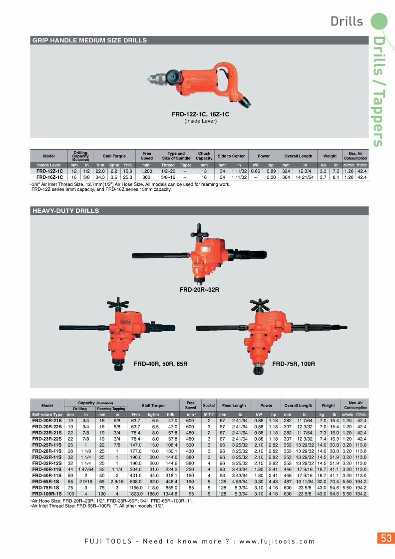
*Air Hose Size: FRD-20R~23R: 1/2", FRD-25R~50R: 3/4", FRD-65R~100R: 1".*Air Inlet Thread Size: FRD-65R~100R: 1". All other models: 1/2".
FRD-75R, 100R
FRD-20R~32R
Max. AirConsumptionStall Torque Socket Feed Length Overall Length Weight
FRD-20R-21S 19 3/4 16 5/8 63.7 6.5 47.0 600 2 67 2 41/64 0.88 1.18 282 11 7/64FRD-20R-22S 19 3/4 16 5/8 63.7 6.5 47.0 600 3 67 2 41/64 0.88 1.18 307 12 3/32FRD-23R-21S 22 7/8 19 3/4 78.4 8.0 57.8 480 2 67 2 41/64 0.88 1.18 282 11 7/64FRD-23R-22S 22 7/8 19 3/4 78.4 8.0 57.8 480 3 67 2 41/64 0.88 1.18 307 12 3/32FRD-25R-11S 25 1 22 7/8 147.0 15.0 108.4 530 3 96 3 25/32 2.10 2.82 353 13 29/32FRD-28R-11S 28 1 1/8 25 1 177.0 18.0 130.1 430 3 96 3 25/32 2.10 2.82 353 13 29/32FRD-32R-11S 32 1 1/4 25 1 196.0 20.0 144.6 380 3 96 3 25/32 2.10 2.82 353 13 29/32FRD-32R-12S 32 1 1/4 25 1 196.0 20.0 144.6 380 4 96 3 25/32 2.10 2.82 353 13 29/32FRD-40R-11S 44 1 47/64 32 1 1/4 304.0 31.0 224.2 220 4 93 3 43/64 1.80 2.41 446 17 9/16FRD-50R-11S 50 2 50 2 431.0 44.0 318.1 150 4 93 3 43/64 1.80 2.41 446 17 9/16FRD-65R-1S 65 2 9/16 65 2 9/16 608.0 62.0 448.4 190 5 125 4 59/64 3.30 4.43 487 19 11/64FRD-75R-1S 75 3 75 3 1156.0 118.0 855.0 85 5 128 5 3/64 3.10 4.16 600 23 5/8FRD-100R-1S 100 4 100 4 1823.0 186.0 1344.8 55 5 128 5 3/64 3.10 4.16 600 23 5/8
7.0 15.4 1.20 42.4 7.0 15.4 1.20 42.4 7.3 16.0 1.20 42.4 7.4 16.3 1.20 42.4 14.0 30.8 3.20 113.0 14.0 30.8 3.20 113.0 14.5 31.9 3.20 113.0 14.5 31.9 3.20 113.0 18.7 41.1 3.20 113.0 18.7 41.1 3.20 113.0 32.0 70.4 5.50 194.2 43.0 94.6 5.50 194.2 43.0 94.6 5.50 194.2
ModelCapacity (Guidance)
Drilling Reaming TappingkgmmSelf-return Type N•m kgf•m ft•lb
FreeSpeed
min-1 M.T.# inmminmm
Power
hpkW m3/minlb ft3/minin mm in
FRD-12Z-1C 12 1/2 22.0 2.2 15.9 1,200 1/2–20 – 13 34 1 11/32 0.66 0.89 FRD-16Z-1C 16 5/8 34.3 3.5 25.3 800 5/8–16 – 16 34 1 11/32 – 0.00
324 12 3/4 3.3 7.3 1.20 42.4 364 14 21/64 3.7 8.1 1.20 42.4
kgmm N•m kgf•m ft•lbInside Lever min-1 in inThread Taper mm mm mm m3/minlb ft3/minin
Max. AirConsumptionOverall LengthSide to Center
DrillingCapacity(Guidance)
Stall TorqueModelFree
SpeedType and
Size of SpindleChuck
Capacity Weight
kW hp
Power
*3/8" Air Inlet Thread Size. 12.7mm(1/2") Air Hose Size. All models can be used for reaming work. FRD-12Z series 8mm capacity, and FRD-16Z series 13mm capacity.
FRD-12Z-1C, 16Z-1C(Inside Lever)
FRD-40R, 50R, 65R
GRIP HANDLE MEDIUM SIZE DRILLS
HEAVY-DUTY DRILLS

Fuji Baby Angle Drills are equipped with a compact head (low height and side-to-center head dimensions) to allow these tools to be used in confined areas. Ball and needle bearings used throughout angle heads provide long service life and less spindle run-out.
Snake Drill Bits 2mm to 6mm and Drill Chuck capacities1/16" to 1/4" are available on request.FCD-6B-1F
SNAKE DRILLS(SN-2~6)
DRILL CHUCKS(CN-1802~1807)
31 8.5
Thread1/4–28
Thread1/4–28
Max. AirConsumption
Air HoseSizeStall Torque
SpindleThread Size
DrillingCapacity(Guidance)
Side to Center Overall LengthPower
FreeSpeed
ChuckCapacity Weight
FCD-6X-1F 6 1/4 4.9 0.50 3.6 2,500 3/8–24UNF 6.5 21 53/64 0.34 0.46 267 10 33/64 1.7 3.7FCD-6X-2F 8 5/16 7.8 0.80 5.7 1,500 3/8–24UNF 8.0 21 53/64 0.29 0.39 281 11 1/16 1.9 4.1FCD-10X-1F 10 7/16 11.8 1.20 8.6 1,200 1/2–20UNF 10.0 21 53/64 0.42 0.56 377 14 27/32 2.2 4.8
0.68 24.0 9.5 3/8 0.68 24.0 9.5 3/8 0.50 17.6 9.5 3/8
Model
kgN•m kgf•m ft•lb min-1 in inmmin kW hpin mmmm mmm3/minlb ft3/minmmLocking Lever in
Fuji utilizes their power transmission knowledge in their line of corner drills. In addition to their power, these drills are designed to work well in confined spaces.
*1/4" Air Inlet Thread Size, All models are Rear Exhaust types.
FCD-6X-1F, 2F FCD-10X-1F
Max. AirConsumption
Air HoseSizeStall Torque
DrillingCapacity(Guidance)
Side toCenter Overall LengthPower Weight
Air InletThread
SizeModel
kgN•m kgf•m ft•lb
FreeSpeed
min-1 in inmmin
Spindle ThreadSize
in mm hpkW mmBSP or NPTm3/minlb ft3/minmm in
Front Exhaust TypeFCD-6B-1F 6 1/4 2.5 0.25 1.8 2,500 1/4–28UNF 9.5 3/8 0.16 0.21 222 8 47/64 0.60 1.3 0.56 19.8 1/4 6.3 1/4
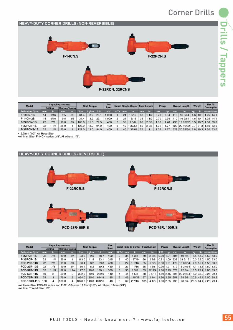
F-22RCR-1S 22 7/8 19.0 3/4 93.2 9.5 68.7 400 2 35 1 3/8 60 2 3/8 0.90 1.21 F-32RCR-1S 32 1 1/4 25.0 1 113.0 11.5 83.1 315 3 40 1 37/64 60 2 3/8 0.81 1.09 FCD-23R-11S 22 7/8 19.0 3/4 80.4 8.2 59.3 430 2 27 1 1/16 35 1 3/8 0.90 1.21 FCD-23R-12S 22 7/8 19.0 3/4 80.4 8.2 59.3 430 3 27 1 1/16 35 1 3/8 0.90 1.21 FCD-32R-11S 32 1 1/4 32.0 1 1/4 177.0 18.0 130.1 350 3 35 1 3/8 53 22 3/4 1.60 2.15 FCD-50R-11S 50 2 50.0 2 392.0 40.0 289.0 140 4 41 1 5/8 58 2 5/16 1.60 2.15 FCD-75R-11S 75 3 75.0 3 834.0 85.0 614.8 85 5 49 1 15/16 57 2 1/4 1.90 2.55 FCD-100R-11S 100 4 100.0 4 1370.0 140.0 1012.6 40 5 62 2 7/16 105 4 1/8 1.90 2.55
ModelMax. Air
ConsumptionStall Torque Socket Feed Length PowerSide to Center Overall LengthFree
Speed WeightCapacity (Guidance)
Drilling Reaming Tappingkgmm N•m kgf•m ft•lb min-1 M.T.# inmminmm inmm kW hp m3/minlb ft3/minin mm in
505 19 7/8 8.5 18.7 1.50 53.0 538 21 3/16 10.0 22.0 1.50 53.0 472 18 37/64 7.0 15.4 1.50 53.0 472 18 37/64 7.1 15.6 1.50 53.0 578 22 3/4 13.5 29.7 1.80 63.5 595 23 27/64 16.0 35.2 2.25 79.4 651 25 5/8 20.5 45.1 2.50 88.3 730 28 3/4 29.3 64.4 2.25 79.4
*12.7mm (1/2") Air Hose Size.*Air Inlet Size: F-14CN series: 3/8", All others: 1/2".
F-14CN.S
F-32RCN, 32RCNS
F-22RCN.S
F-14CN-1S 14 9/16 9.5 3/8 31.4 3.2 23.1 1,000 1 24 15/16 38 1 1/2 0.70 0.94 F-14CN-2S 14 9/16 9.5 3/8 31.4 3.2 23.1 1,000 2 24 15/16 38 1 1/2 0.70 0.94 F-22RCN-1S 22 7/8 19.0 3/4 108.0 11.0 79.5 450 2 35 1 3/8 60 2 3/8 1.10 1.48 F-32RCN-1S 32 1 1/4 25.0 1 127.0 13.0 94.0 400 3 40 1 37/64 60 2 3/8 1.32 1.77 F-32RCNS-1S 32 1 1/4 25.0 1 127.0 13.0 94.0 400 3 40 1 37/64 25 1 1.32 1.77
Model
Self-return Type
Self-return Type
Max. AirConsumptionStall Torque Socket Feed Length PowerSide to Center Overall Length
FreeSpeed Weight
410 16 9/64 4.6 10.1 1.25 44.1 410 16 9/64 4.6 10.1 1.25 44.1 493 19 13/32 8.5 18.7 1.50 53.0 523 20 19/32 9.7 21.3 1.50 53.0 529 20 53/64 8.8 19.3 1.50 53.0
Capacity (Guidance)
Drilling Reaming Tappingkgmm N•m kgf•m ft•lb min-1 M.T.# inmminmm inmm kW hp m3/minlb ft3/minin mm in
*Air Hose Size: FCD-23 series and F-22, -32series 12.7mm(1/2"), All others: 19mm (3/4") .*Air Inlet Thread Size: 1/2".
FCD-23R~50R.S FCD-75R, 100R.S
F-32RCR.SF-22RCR.S
HEAVY-DUTY CORNER DRILLS (NON-REVERSIBLE)
HEAVY-DUTY CORNER DRILLS (REVERSIBLE)
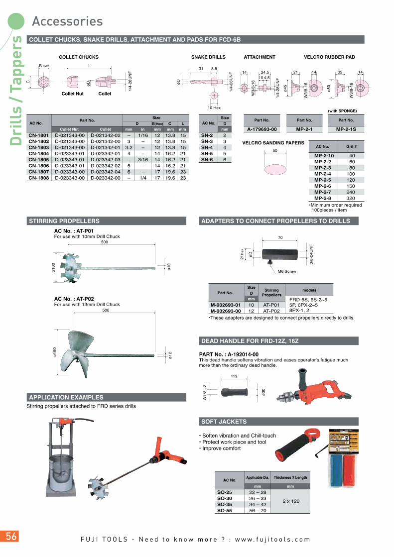
Stirring propellers attached to FRD series drills
500
ø10
0
ø10
500
ø19
0
ø12
AC No. : AT-P01For use with 10mm Drill Chuck
AC No. : AT-P02For use with 13mm Drill Chuck
Part No.
CN-1801 D-021343-00 D-021342-02 – 1/16 12 13.8 15CN-1802 D-021343-00 D-021342-00 3 – 12 13.8 15CN-1803 D-021343-00 D-021342-01 3.2 – 12 13.8 15CN-1804 D-023343-01 D-023342-01 4 – 14 16.2 21CN-1805 D-023343-01 D-023342-03 – 3/16 14 16.2 21CN-1806 D-023343-01 D-023342-02 5 – 14 16.2 21CN-1807 D-023343-00 D-023342-04 6 – 17 19.6 23CN-1808 D-023343-00 D-023342-00 – 1/4 17 19.6 23
AC No.
Collet inmm mm mm mmCollet Nut
Size
D B(Hex) C L
Size
Collet Nut Collet
B Hex L
C
øD
1/4-
28U
NF
31 8.5
øD
1/4-
28U
NF
10 Hex
SN-2 2SN-3 3SN-4 4SN-5 5SN-6 6
AC No.
mmD
MP-2-10 40MP-2-2 60MP-2-3 80MP-2-4 100MP-2-5 120MP-2-6 150MP-2-7 240MP-2-8 320
AC No. Grit #
SizeStirring
Propellersmodels
M-002693-01 10 AT-P01M-002693-00 12 AT-P02
Part No.
Thickness x LengthApplicable Dia.AC No.
A-179693-00
Part No.
mmD
PART No. : A-192014-00This dead handle softens vibration and eases operator's fatigue much more than the ordinary dead handle.
• Soften vibration and Chill-touch• Protect work piece and tool• Improve comfort
W1/
2-12
119
ø30
VELCRO SANDING PAPERS
ATTACHMENTCOLLET CHUCKS SNAKE DRILLS
MP-2-1
Part No.
VELCRO RUBBER PAD
MP-2-1S
Part No.
(with SPONGE)
70
M6 Screw
øD
3/8-
24U
NF
21H
ex
144.510
24.5
W3/
8-16
1/4-
28U
NF
ø45
W3/
8-16
21 14
ø50
W3/
8-16
32 14
50
*These adapters are designed to connect propellers directly to drills.
FRD-5S, 6S-2~55P, 6PX-2~58PX-1, 2
SO-25 22 – 28SO-30 26 – 33SO-35 34 – 42
2 x 120
SO-55 56 – 70
mm mm
* Minimum order required :100pieces / item
COLLET CHUCKS, SNAKE DRILLS, ATTACHMENT AND PADS FOR FCD-6B
STIRRING PROPELLERS ADAPTERS TO CONNECT PROPELLERS TO DRILLS
DEAD HANDLE FOR FRD-12Z, 16Z
SOFT JACKETS
APPLICATION EXAMPLES
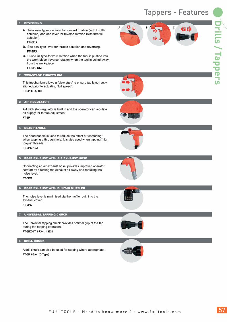
A. Twin lever type-one lever for forward rotation (with throttle actuaion) and one lever for reverse rotation (with throttle actuaion).
FT-6BX
B. See-saw type lever for throttle actuaion and reversing.
FT-8PX
C. Push/Pull type-forward rotation when the tool is pushed into the work-piece, reverse rotation when the tool is pulled away from the work-piece.
FT-6P, 13Z
This mechanism allows a "slow start" to ensure tap is correctly aligned prior to actuating "full speed".
FT-6P, 8PX, 13Z
A 4 click stop regulator is built in and the operator can regulate air supply for torque adjustment.
FT-6P
The dead handle is used to reduce the effect of "snatching" when tapping a through hole. It is also used when tapping "high torque" threads.
FT-8PX, 13Z
Connecting an air exhaust hose, provides improved operator comfort by directing the exhaust air away and reducing the noise level.
FT-6BX
The noise level is minimised via the muffler built into the exhaust cover.
FT-8PX
The universal tapping chuck provides optimal grip of the tap during the tapping operation.
FT-6BX-1T, 8PX-1, 13Z-1
A drill chuck can also be used for tapping where appropriate.
FT-6P, 6BX-1(D Type)
2 TWO-STAGE THROTTLING
3 AIR REGULATOR
4 DEAD HANDLE
5 REAR EXHAUST WITH AIR EXHAUST HOSE
6 REAR EXHAUST WITH BUILT-IN MUFFLER
7 UNIVERSAL TAPPING CHUCK
8 DRILL CHUCK
1 REVERSING
A B CL R
RL
PUSHR
PULLL

Easy to use throttle and reversing trigger combined with a universal tapping chuck provide a smooth tapping operation. Fuji Tappers are available in tapping capacities from 6mm to 13mm.
FT-8PX-1
FT-6BX-1(Drill Chuck type)
FT-6BX-1(Universal Tapping Chuck type)
FT-6P-1
TCK-6 FT-6BX-1T J.T.#1 8mmTCK-8F FT-8PX-1 M.T.#1 9mm
Models Type and Size of SpindleTaper #
Chuck CapacityNo.
DCK-6.5J FT-6BX-1(D Type) J.T.#1 6.5mmDCK-8J FT-6P-1 J.T.#1 8mm
Models Type and Size of SpindleTaper #
Chuck CapacityNo.
*FT-6P-1, 6BX-1, 8PX-1: 1/4" Air Inlet Thread Size. *TYPE: D...Drill Chuck, T...Tapping Chuck.
Max. AirConsumptionOverall Length Weight Air Hose Size
FT-6P-1 6 1/4 8 5/16 1,000 1,000 J.T.#1 8 236 9 19/64 1.8 4.0FT-6BX-1 6 1/4 8 5/16 2,000 2,000 J.T.#1 6.5 205 8 7/64 1.3 2.9FT-6BX-1 6 1/4 8 5/16 2,000 2,000 J.T.#1 8 240 9 29/64 1.3 2.9FT-8PX-1 8 5/16 10 3/8 450 450 M.T.#1 9 232 9 9/64 2.0 4.4
0.50 17.7 9.5 3/8 0.56 19.8 8.0 5/16 0.56 19.8 8.0 5/16 0.50 17.7 9.5 3/8
Model TypeTapping Capacity (Guidance) Free
Speed(min-1)Type and Size
of SpindleChuck
CapacitySteel AluminumkgTaper # in inmmmm mmm3/minlb ft3/minmm mmin in R L
–DT–
TAPPING CHUCKS
DRILL CHUCKS


A
C
B
1 VALVE MECHANISM
2 LOW AIR CONSUMPTION
3 QUICK CHANGE ATTACHMENTS FOR PERCUSSIVE TOOLS
5 PLASTIC HANDLE COVER
4 MULTI-NEEDLES
Equipped with following valve mechanism, Fuji Percussion Tools have trouble-free long life.
A. PLATE VALVE
Plate valve consists of four parts of valve sheet, valve cover, valve case and valve. This simple mechanism and plate valve surface provide longer durability.
FR Series
B. SLEEVE VALVE
Hollow valve enables a light and compact body and longer stroke for its size.
FRH Series
C. PISTON VALVE
High blow frequency (60Hz to 90Hz) can be maintained as this piston functions as a valve providing high working efficiency.
FCH Series, FNS Series and FS Series
Low air consumption 0.14-0.18 m3/min (due to the valve mechanism) enables Fuji Percussion Tools to be used with a smaller compressor.
FCH Series and FNS Series
Attachment, such as chisels and needles, can be quickly and easily changed.
FCH Series and FNS Series
Fuji Needle Scalers utilise multiple needles that do not contaminate the workpiece.
FNS Series
The plastic handle cover reduces the effect of vibration and provides an insulated grip for the operator.
FNS-2P-1F

A B
6 SCALING HEADS
7 LOCKING HANDLE
8 TUNGSTEN CARBIDE TIPPED PISTON (OPTION)
9 LOW BLOW FREQUENCY
11 CHISEL HOLDER
10 CHISEL RETAINER
Three models are available to suit different applications- single head, dual head and triple head.
FS Series
The locking handle are designed to reduce the risk of accidental starting of the tools. The handle is automatically locked when the operator releases the handle.
Locking Lever Handle
FS, FR, FCH, FNS Series
4-point Tungsten Carbide Piston is available on request for heavy removal operations.
FS Series
The built-in Sleeve Valve allows the operator to adjust the blow frequency by adjusting the throttle valve.
FRH Series
A. Holder Spring (Bee-Hive Retainer)B. Holder Spring (B) (Quick Change Retainer)
FRH Series, FC-01SA
Fuji Chipping and Calking Hammers are supplied with a chisel retainer as standard. This reduces the risk of the chisel releasing during operation.
FC Series

Fuji offers 3 variants of Flux Chippers with different removal rates. They are ideal for various removal operations like light chipping, carving stone, scaling, removing paint, rust, weld flux and light fins from castings. FCH-25B offers a "blow" function which is ideal for blowing particles away from the work piece.
FCH-20-1F 90 20 25/32 16 5/8 176 6 13/64 0.8 1.8 0.14 4.9 1/4 6.3 1/4FCH-20F-1F 90 20 25/32 16 5/8 182 7 5/32 1.0 2.2 0.14 4.9 1/4 9.5 3/8FCH-25-1F 60 25 1 20 25/32 204 8 1/32 1.5 3.3 0.18 6.4 1/4 9.5 3/8FCH-25B-1F 60 25 1 20 25/32 239 9 13/32 1.7 3.7 0.18 6.4 1/4 8.0 5/16
Model
m3/minkgmm in lb mmBSP or NPTft3/min ininHzLocking Lever mm in mm
Piston Diameter Overall Length Air Hose SizeBlows WeightAir Consumption
(At Load)Air Inlet
Thread SizeStroke
FCH-20F-1F FCH-25-1F FCH-25B-1F(Separate Blow Type)
FRH-3-1 Hex 3.2 2.5 60 14.3 9/16 38.0 1 1/2 140 5 33/64 1.1 2.4 0.35 12.4FRH-3-2 Round 3.2 2.5 60 14.3 9/16 38.0 1 1/2 140 5 33/64 1.1 2.4 0.35 12.4FRH-6-1 Hex 6.4 5.0 30 12.7 1/2 100.0 4 206 8 7/64 1.4 3.0 0.35 12.4FRH-6-2 Round 6.4 5.0 30 12.7 1/2 100.0 4 206 8 7/64 1.4 3.0 0.35 12.4FRH-6A-1 Hex 6.4 5.0 50 20.0 25/32 44.5 1 3/4 193 7 19/32 1.5 3.3 0.40 14.1FRH-6A-2 Round 6.4 5.0 50 20.0 25/32 44.5 1 3/4 193 7 19/32 1.5 3.3 0.40 14.1
1/4 9.5 3/8 1/4 9.5 3/8 1/4 9.5 3/8 1/4 9.5 3/8 1/4 9.5 3/8 1/4 9.5 3/8
Model
m3/minkgmm in lb mmBSP or NPTft3/min ininHzDuralmin Steel mm in mm
Piston Diameter Overall Length Air Hose SizeBlows WeightAir Consumption
(At Load)ChiselShank
Riveting Capacity(mm)
Air InletThread SizeStroke
Fuji Light Hammers provide a controllable impact for rivetting to reduce the effect of work hardening of the rivet or damage to the surrounding metal. These tools are easily adapted to perform other operations, such as cutting, ripping, shearing, punching and gouging with suitable chisels fitted.
FRH-3 FRH-6 FRH-6A
FRH-SERIES KIT
FRH-ModelAir RegulatorHose NippleHolder SpringHolder Spring (B)7 kinds of ChiselMetal Carrying Case
Fuji Needle Scalers are useful for removing weld flux, sand from castings, scales from forgings, rust, paint, scales from ship hulls and finishing rough surfaces of rock or concrete. Fuji Needle Scalers feature a unique valve less design and work well on uneven or irregular surfaces.
FNS-2P-1F
MOVEMENT OF NEEDLES
*Specify needle diameter (3mm or 2mm) when ordering.
FNS-2-1F Straight 133 25 1 180 7 3/32 19 37 7 9/32 325 12 51/64 1.9 4.1FNS-2P-1F Pistol 133 25 1 180 7 3/32 19 37 7 9/32 371 14 39/64 2.5 5.5
0.18 6.4 1/4 9.5 3/8 0.18 6.4 1/4 9.5 3/8
Model
m3/minkgmm in mm in lb mmBSP or NPTft3/min in2mmHz mm mmin in 3mm
Needle Length Overall LengthAir Hose
SizeBlows WeightAir Consumption
(At Load)ThrottleType
No. and Diaof Needle
PistonDiameter
Air InletThread SizeNeedle Stroke
Locking Lever
FNS-2-1F

Fuji offers 1, 2 and 3-Head Scaling Hammers. These tools have proven to be very efficient in cleaning heavily oxidized surfaces which occur on ships' hulls, bridges and storage tanks.
FS-2A-1F
FS-2A-1F 1 133 30 1 3/16 16 5/8 94 3 11/16 510(537) 20 5/64(21 9/64) 2.5 5.5 0.25 8.8 3/8
Model
m3/minkgmm in lbmm BSP or NPTft3/minininHz mm in mm
Piston Diameter Overall LengthAngle HeightNumberof
Cylinder
Blows WeightAir Consumption
(At Load)Air Inlet
Thread SizeStroke
*9.5mm (3/8") Air Hose.
FR-18B-2F 30 18.0 45/64 50 1 31/32 41 1 5/8 280(383) 11 1/32(15 5/64) 1.5 3.3 0.40 14.1FR-22B-2F 17 22.0 55/64 64 2 33/64 51 2 1/32 350(451) 13 25/32(17 3/4) 3.0 6.6 0.50 17.7FR-25B-2F 13 25.4 1 83 3 17/64 67 2 41/64 506(597) 19 59/64(23 1/2) 5.5 12.1 0.70 24.7FR-18L-2F 30 18.0 45/64 50 1 31/32 41 1 5/8 558(523) 21 31/32(20 19/32) 2.0 4.4 0.40 14.1FR-22L-2F 17 22.0 55/64 64 2 33/64 51 2 1/32 633(600) 24 59/64(23 5/8) 3.3 7.2 0.50 17.7FR-25L-2F 13 25.4 1 83 3 17/64 67 2 41/64 1,043(1,005) 41 1/16(39 9/16) 6.0 13.2 0.70 24.7FR-32-2F 12 32.0 1 17/64 127 5 75 2 61/64 1,086(1,090) 42 3/4(42 29/32) 10.0 22.0 0.80 28.2
1/4 9.5 3/8 3/8 9.5 3/8 3/8 12.7 1/2 1/4 9.5 3/8 1/4 9.5 3/8 1/2 12.7 1/2 1/2 12.7 1/2
m3/minkgmmmm inin lb mmBSP or NPTft3/min ininHzLocking Lever mm in mm
Overall LengthButt DiameterBlows WeightAir InletThread
Size
AirConsumption
(At Load)Piston
DiameterAir Hose
SizeStrokeModel
Fuji Sand Rammers are powerful but light with a stroke range from 50mm to 127mm. Fuji Sand Rammers are excellent for ramming sand for casting in any ferrous or non-ferrous foundry. Non-rotary type rammers are available for use with irregular shaped butts.
FR-18L-2F~32-2F
FR-18B-2F~25B-2F

27L
2020 4
ø11
ø12 ø159
L
2020 420
ø11
ø12 ø15
9
4
G-1-1 125 G-1-2 155 Blank G-1-3 200 G-1-4 250 G-1-5 300 G-2-1 130 G-2-2 155 Flat G-2-3 200 G-2-4 250 G-2-5 300
Type AC No.
mm
Size
L
F-1-1 140 F-1-2 155 Blank F-1-3 200 F-1-4 250 F-1-5 300
Type AC No.
mm
Size
L
TWH-0006 4 2.5 x 2.5 x 5
AC No.
l x w x LPoint
Tip Size
F-2-2 155 F-2-3 200 Flat F-2-4 250 F-2-5 300 F-2-7 400
Type AC No.
mm
Size
L
F-3-2 155 F-3-3 200 Flux F-3-4 250 F-3-5 300 F-3-7 400
Type AC No.
mm
Size
L
S-1 120 Standard
Point S-3 160 Small Point
S-2 120 Standard
Flat S-4-1 160 Small Flat
Type AC No. Remark
mm
OverallLength
25
L
3625
25
ø12
12.7
ø9.53
3.6
ø12
15.5
L
3625
2538
ø9.53
3.6
12.7
ø12
25
L
3625
2545
30˚
ø9.53
3.6
12.7
l
w
L
TWH-0007 4 6 x 6 x 12
TWH-0003 9 5 x 5 x 15
TWH-0002 16 4 x 4 x 16
TWH-0004 25 4.5 x 4.5 x 22.5
AC No.
l x w x LPoint
Tip Size
l
w
L
l
w
L
L
L
l
w
l
w
CHISELS FOR FCH-20 TIPPED CHISELS FOR FCH-20
BUSHING CHISELS FOR FCH-20
CHISELS FOR FCH-20F, 25 AND 25B
BUSHING CHISELS FOR FCH-20F, 25 AND 25B

AC No.Part Name
808 WA-808 WA-808H Muffler Cutter 809 WA-809 WA-809H Double Edge Panel Cutter 810 WA-810 WA-810H Flat Chisel 812 WA-812 WA-812H Taper Punch 813 WA-813 WA-813H Rivet Cutter 814 WA-814 WA-814H Blank Chisel 815 WA-815 WA-815H Spot Weld Breaker
Index No.
HexagonalRound43.5
29.56
R12.7ø19
ø10
.185
ø12
.7
24
43.5
29.46
ø10
.185
ø19
ø12
.7
8.7Hex
R12.7
Round shank Hexagonal shank
810
812
809
808
13
53
5515˚
208
10
2
813
814
815
23
58155
196
27
65178
203
50178
3.2
66150
45
1512
.7
182
12.7
35145
5028
13.5
19 7
CHISELS FOR FRH SERIES

Holder Spring (B) R Size Rivet Size
SNAP-3 3.0 3 SNAP-4 3.7 4 SNAP-5 4.8 5 SNAP-6 5.1 6
AC No.
mm mmPart No.Part Name
H-043715-00 H-019715-00 H-024715-00 Holder Spring H-043719-00 H-019719-00 H-024719-01 Holder Spring (B)
FC-01SA FRH-3, 6 FRH-6A
90
29.56
R12.7
43.546.5
R
ø10
.185
ø12
.7Holder Spring
ø19
RUBBER BUTTS FOR FR-SERIES
RETAINER FOR FRH SERIES RIVET SNAPS FOR FRH SERIES
Model
R-1 51 11.8 60 FR-18B, 18L R-1-1 41 12.7 47 FR-18B, 18L R-2 51 13.75 60 FR-22B, 22L R-3 67 17.25 80 FR-25B, 25L R-4 75 18.75 92 FR-32
AC No.
mm mm mm
Size
d HD
D
d
H


Fuji Air Motors are compact and light weight, yet sturdy and offer high power-to-weight ratios. Fuji offers a wide range of air motors from small 0.1 kW hand-held motor to large 20 kW stationary motor which are found at versatile industries like ships, chemical plants, mines and power plants etc. As air motors are less likely to generate sparks (unlike brushes in electric motors), they are better suited for use in hazardous environments.
F-5SM-2R F-6SM-2.5R~28RF-5SM-8.5R
F-8SM-12R~28R
F-5SM-8.5R 5.4 0.55 4.0 0.12 0.16 850 147 5 51/64 0.6 1.3F-5SM-2R 21.6 2.20 15.9 0.10 0.14 190 182 7 11/16 0.8 1.8F-6SM-28R 3.3 0.34 2.5 0.25 0.34 2,300 147 5 51/64 0.8 1.8F-6SM-21R 4.0 0.41 3.0 0.26 0.35 2,000 146 5 3/4 0.9 2.0F-6SM-12R 5.9 0.60 4.3 0.23 0.31 1,000 157 6 3/16 0.8 1.8F-6SM-8R 9.8 1.00 7.2 0.23 0.31 750 179 7 1/16 1.0 2.2F-6SM-5R 14.7 1.50 10.8 0.22 0.30 500 180 7 3/32 1.0 2.2F-6SM-2.5R 26.0 2.65 19.2 0.21 0.29 250 192 7 9/16 1.2 2.6F-8SM-28R 6.4 0.65 4.7 0.38 0.52 2,300 183 7 13/64 1.5 3.3F-8SM-12R 9.8 1.00 7.2 0.37 0.50 1,100 199 7 53/64 2.2 4.8F-8SM-8.5R 14.7 1.50 10.8 0.37 0.50 850 222 8 3/4 2.4 5.3
0.28 9.9 1/8 6.3 1/4 0.28 9.9 1/8 6.3 1/4 0.34 12.0 1/8 8.0 5/16 0.34 12.0 1/8 8.0 5/16 0.34 12.0 1/8 8.0 5/16 0.34 12.0 1/8 8.0 5/16 0.34 12.0 1/8 8.0 5/16 0.34 12.0 1/8 8.0 5/16 0.50 17.7 1/4 9.5 3/8 0.50 17.7 1/4 9.5 3/8 0.50 17.7 1/4 9.5 3/8
Model
m3/minmm in lbkg mmBSP or NPTft3/min inPSN • m kgf • m ft • lb kW
Horse Power Overall Length Air Hose SizeAir InletThread
SizeStall Torque Weight
Max. AirConsumption
FreeSpeed
min-1
*Specify type of spindle when ordering.
Model Model *Model SpindleThread Size
ApplicableDrill Chuck
Type of Spindle Hose Connection
Non-Reversible Type
AIR INLET(R)
Reversible Type
*Drill chucks are applicable to thread type spindle models.
Chord Type Thread TypeKey Type
F-6SM-5, 8, 12, 21 DCK-6.5 F-5SM Series F-8SMA Series F-8SMA-12, 28 3/8-24(UNF) DCK-8 F-6SE, 6SF, 6PFX DCK-10 F-6SM Series F-8SM Series F-8SMA-8.5
1/2-20(UNF) DCK-13 F-10MT
AIR INLET(R)
AIR INLET(L)
AIR EXHAUST
F-8SM-8.5R
F-5SM-8.5 5.9 0.60 4.3 0.13 0.18 950 153 6 1/32 0.6 1.3F-5SM-2 23.5 2.40 17.4 0.12 0.16 200 187 7 3/8 0.9 2.0F-6SM-28 3.9 0.40 2.9 0.29 0.40 2,800 167 6 37/64 0.7 1.5F-6SM-21 4.4 0.45 3.3 0.29 0.40 2,400 167 6 37/64 0.8 1.8F-6SM-12 7.4 0.75 5.4 0.29 0.40 1,300 181 7 1/8 0.9 2.0F-6SM-8 10.8 1.10 8.0 0.26 0.35 900 200 7 7/8 1.0 2.2F-6SM-5 15.7 1.60 11.6 0.26 0.35 600 200 7 7/8 1.0 2.2F-6SM-2.5 28.4 2.90 21.0 0.26 0.35 300 213 8 25/64 1.2 2.6F-8SMA-28 5.9 0.60 4.3 0.44 0.60 2,600 171 6 47/64 1.5 3.3F-8SMA-12 11.8 1.20 8.7 0.44 0.60 1,300 200 7 7/8 2.0 4.4F-8SMA-8.5 16.7 1.70 12.3 0.44 0.60 900 208 8 3/16 2.2 4.8
0.28 9.9 1/8 6.3 1/4 0.28 9.9 1/8 6.3 1/4 0.34 12.0 1/4 9.5 3/8 0.34 12.0 1/4 9.5 3/8 0.34 12.0 1/4 9.5 3/8 0.34 12.0 1/4 9.5 3/8 0.34 12.0 1/4 9.5 3/8 0.34 12.0 1/4 9.5 3/8 0.50 17.7 1/4 9.5 3/8 0.50 17.7 1/4 9.5 3/8 0.50 17.7 1/4 9.5 3/8
F-6SM-2.5~28 F-8SMA-8.5~28F-5SM-2
Model
m3/minmm in lbkg mmBSP or NPTft3/min inPSN • m kgf • m ft • lb kW
Horse Power Overall Length Air Hose SizeAir InletThread
SizeStall Torque Weight
Max. AirConsumption
FreeSpeed
min-1
F-5SM-8.5
*Specify type of spindle when ordering.
REVERSIBLE TYPE
NON-REVERSIBLE TYPE
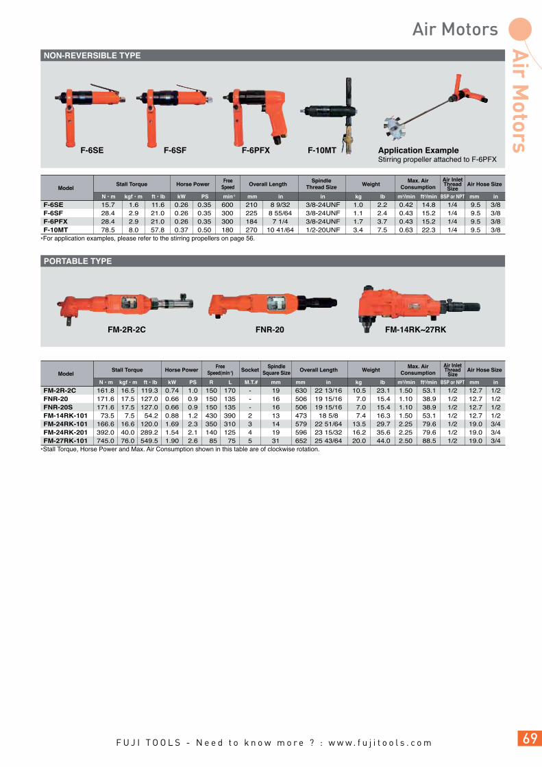
FM-2R-2C 161.8 16.5 119.3 0.74 1.0 150 170 - 19 630 22 13/16 10.5FNR-20 171.6 17.5 127.0 0.66 0.9 150 135 - 16 506 19 15/16 7.0FNR-20S 171.6 17.5 127.0 0.66 0.9 150 135 - 16 506 19 15/16 7.0FM-14RK-101 73.5 7.5 54.2 0.88 1.2 430 390 2 13 473 18 5/8 7.4FM-24RK-101 166.6 16.6 120.0 1.69 2.3 350 310 3 14 579 22 51/64 13.5FM-24RK-201 392.0 40.0 289.2 1.54 2.1 140 125 4 19 596 23 15/32 16.2FM-27RK-101 745.0 76.0 549.5 1.90 2.6 85 75 5 31 652 25 43/64 20.0
23.1 1.50 53.1 1/2 12.7 1/2 15.4 1.10 38.9 1/2 12.7 1/2 15.4 1.10 38.9 1/2 12.7 1/2 16.3 1.50 53.1 1/2 12.7 1/2 29.7 2.25 79.6 1/2 19.0 3/4 35.6 2.25 79.6 1/2 19.0 3/4 44.0 2.50 88.5 1/2 19.0 3/4
Model
m3/minmmmmM.T.# in lbkg mmBSP or NPTft3/min inPSN • m kgf • m ft • lb kW
Horse Power Overall Length Air Hose SizeAir InletThread
SizeStall Torque WeightSocket
Max. AirConsumption
FreeSpeed(min-1)
SpindleSquare Size
R L
*Stall Torque, Horse Power and Max. Air Consumption shown in this table are of clockwise rotation.
FM-2R-2C FM-14RK~27RKFNR-20
F-6SE 15.7 1.6 11.6 0.26 0.35 600 210 8 9/32 3/8-24UNF 1.0 2.2F-6SF 28.4 2.9 21.0 0.26 0.35 300 225 8 55/64 3/8-24UNF 1.1 2.4F-6PFX 28.4 2.9 21.0 0.26 0.35 300 184 7 1/4 3/8-24UNF 1.7 3.7F-10MT 78.5 8.0 57.8 0.37 0.50 180 270 10 41/64 1/2-20UNF 3.4 7.5
0.42 14.8 1/4 9.5 3/8 0.43 15.2 1/4 9.5 3/8 0.43 15.2 1/4 9.5 3/8 0.63 22.3 1/4 9.5 3/8
Model
m3/minmm inin lbkg mmBSP or NPTft3/min inPSN • m kgf • m ft • lb kW
Horse Power Overall Length Air Hose SizeAir InletThread
SizeSpindle
Thread SizeStall Torque WeightMax. Air
ConsumptionFree
Speed
min-1
*For application examples, please refer to the stirring propellers on page 56.
F-6SE F-6SF F-6PFX F-10MT Application ExampleStirring propeller attached to F-6PFX
NON-REVERSIBLE TYPE
PORTABLE TYPE
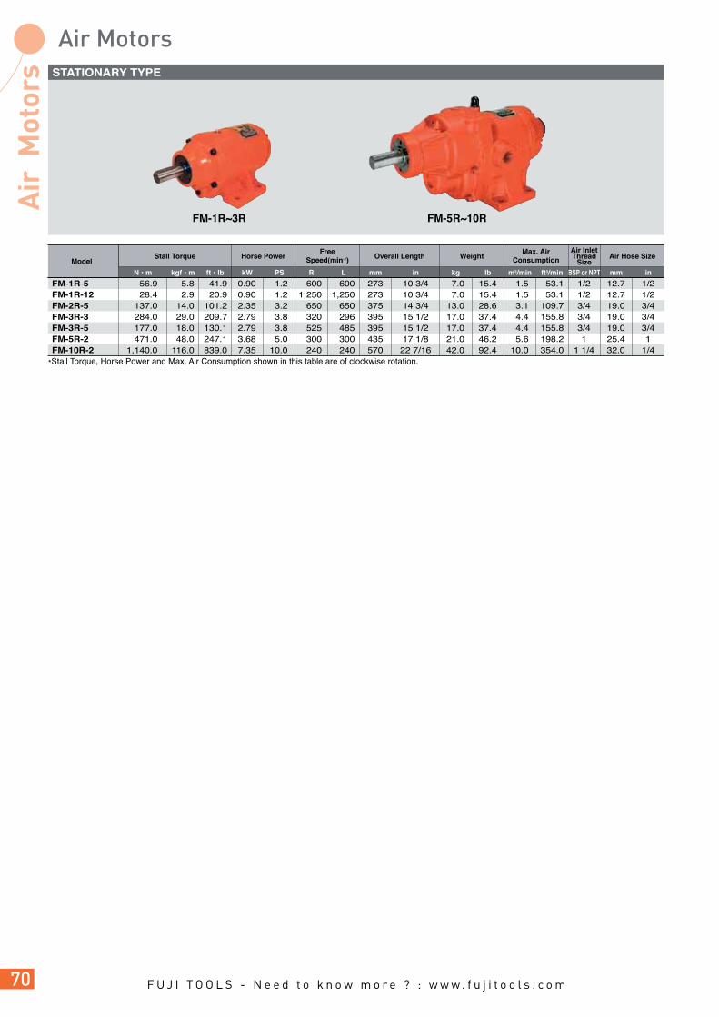
mmBSP or NPTft3/min in
Air Hose Size
FM-1R-5 56.9 5.8 41.9 0.90 1.2 600 600 273 10 3/4 7.0 15.4FM-1R-12 28.4 2.9 20.9 0.90 1.2 1,250 1,250 273 10 3/4 7.0 15.4FM-2R-5 137.0 14.0 101.2 2.35 3.2 650 650 375 14 3/4 13.0 28.6FM-3R-3 284.0 29.0 209.7 2.79 3.8 320 296 395 15 1/2 17.0 37.4FM-3R-5 177.0 18.0 130.1 2.79 3.8 525 485 395 15 1/2 17.0 37.4FM-5R-2 471.0 48.0 247.1 3.68 5.0 300 300 435 17 1/8 21.0 46.2FM-10R-2 1,140.0 116.0 839.0 7.35 10.0 240 240 570 22 7/16 42.0 92.4
1.5 53.1 1/2 12.7 1/2 1.5 53.1 1/2 12.7 1/2 3.1 109.7 3/4 19.0 3/4 4.4 155.8 3/4 19.0 3/4 4.4 155.8 3/4 19.0 3/4 5.6 198.2 1 25.4 1 10.0 354.0 1 1/4 32.0 1/4
Model
m3/minmm in lbkg mmBSP or NPTft3/min inPSN • m kgf • m ft • lb kW
Horse Power Overall Length Air Hose SizeAir InletThread
SizeStall Torque Weight
Max. AirConsumption
FreeSpeed(min-1)
R L
*Stall Torque, Horse Power and Max. Air Consumption shown in this table are of clockwise rotation.
FM-1R~3R FM-5R~10R
STATIONARY TYPE


Fuji Tip Dresser FTD-18 series are designed to be compact, light weight and ideal for dressing tips in narrow space between opposing tips on electric spot welders. Patent applied FTD-18A clamp system provides excellent tip center alignment and accurate tip repairing. Various types of welding tips can be dressed by replacing cutter and cutter case.
FTD-18-1 12~16 15/32~5/8 – – 1,300 290 11 7/16 1.65 3.64 0.5 17.7 BSP or NPT 1/4 9.5 3/8FTD-18A-1 13~16 33/64~5/8 25 63/64 1,300 307 12 3/32 2.02 4.45 0.5 17.7 BSP or NPT 1/4 9.5 3/8
Model
m3/minkg mmmm in lb ininft3/minmmmm in in
Overall Length WeightCapacity Tip Size Air Inlet Thread Size Air Hose SizeMax. Air
ConsumptionFree
SpeedMax. Clamp
Height
min-1
(1) CUT-1001 6R ø12 6R x ø12 CUT-1002 6.5R ø13 6.5R x ø13 CUT-1003 8R ø16 8R x ø16 (2) CUT-2001 16R x ø16 – 10R~150R ø16 – (3) – øA x 6R ø12 – – øA x 6.5R ø13 – CUT-3001 ø5 x 8R x ø16 CUT-3002 øA x 8R ø16 ø6 x 8R x ø16 (4) – r x øA x 6R ø12 – CUT-1002 r x øA x 6.5R ø13 – CUT-1003 r x øA x 8R ø16 40r x ø6 x 8R x ø16 (5) – 5~6r x 60˚ ø13 – – 3r or more x 90˚ ø16 – (6) – 7~ø9 x 50˚ ø13 – – ø10 or more x 50˚ ø16 – CUT-6001 5~ø7 x 60˚ ø13 ø6 x 60˚ x ø13 – ø8 or more x 60˚ ø16 – – 3~ø4 x 75˚ ø13 – CUT-6002 ø5 or more x 75˚ ø16 ø6 x 75˚ x ø16 CUT-6003 ø3 or more x 90˚ ø16 ø4 x 90˚ x ø16 CUT-6004 ø3 or more x 90˚ ø16 ø6 x 90˚ x ø16 – ø3 or more x 120˚ ø16 – (7) – r x øA x ˚ øD – (8) – øA x r x ˚ øD – (9) – F ø16 –
StandardItem No.TypeMax. diameterrepaired(øD)
Tip shape(Nominal)
*Beside item listed above table, minimum 10pcs. per item is required for ordering optional cutters. Specify the nominal dimensions when ordering.
*Cutter is not provided as a standard accessory.
S-167716-00 16 S-167716-01 13 S-167716-02 12
Item No.
FTD-18-1 FTD-18A-1
(1)
R x øD
(2)
R x øD
(3)
øA x R x øD
(4)
r x øA x R x øD
(5)
r x ˚ x øD
(6)
øA x ˚ x øD
(7)
r x øA x ˚ x øD
(8)
øA x r x ˚ x øD
(9)
F x øD
<FTD-18A-1> PAT.P
*Cutter dresses Welding Tip correctly as inside diameter (øD) of cutter case act as a guide. Specify cutter case diameter which matches tip size. ø16 cutter case is included as a standard accessory. Specify cutter case ø12 or ø13 otherwise.
Holder
TIP
D
D D D D
D D D
r
rD
R R
R
A
R
Ar
rA A A
øD
øD
ø22.2
CLASSIFICATION TABLE FOR CUTTERS
CUTTER CASES
SHAPES OF TIPS AND CUTTERS

StrokePer
MinuteSPM
ToolName
Air HoseSize
Air InletThread
Size
FRF-4-1F File 1,600 12.0 15/32 4.0 x 13.0 x 20 5/32 x 1/2 x 25/32 229 9 1/32 0.8 1.7 0.28 9.9 1/4 6.3 1/4FRF-4-2F Saw 1,600 12.0 15/32 2.0 x 13.0 x 20 5/64 x 1/2 x 25/32 233 9 3/16 0.8 1.7 0.28 9.9 1/4 6.3 1/4FRS-45 Saw 1,200 45.0 1 25/32 2.5 x 17.7 x 31 3/32 x 45/64 x 1 7/32 419 16 1/2 2.9 6.3 0.40 14.1 1/4 9.5 3/8
Model
kgin in in inmm mm mm mmBSP or NPTm3/minlb ft3/min
Max. AirConsumption
OverallLength WeightStroke Chuck Capacity
FRF-4-1, 2 FRS-45
Fuji FRF series compact Air File & Saws feature reduced vibration and are designed for deburring, filing and cutting of metal, wood, plastic, and fibreglass.The FRS-45 Air Saw is equipped with a damper to minimize vibration and, a stroke regulator and blade cooling device. The cutting direction is adjustable to provide optimal operator comfort.
*Models marked 1F, 2F are locking lever handle types.
1
2
3
4
5
L
W
12
IndexNo.
1 •FILE-4P Pillar 2 FILE-4H Half Round 3 FILE-4R Round 150 4 FILE-4C Triangle 5 FILE-4S Square
AC No. Name
mm
OverallLength
* • =Accessories included in FRF-4-1, 1F
AC No.
•SAW-4 123 25
LW
Size
mm
* • =Accessories included in FRF-4-2, 2F. W =The number of teeth per inch.
L22
W
18
AC No. Cutting Materials
SAW-2014 200 14 steel plate, pipe, copper, brass, plastic, slate •SAW-2018 200 18 steel plate, pipe •SAW-2024 200 24 steel plate, pipe SAW-2514 250 14 steel plate, pipe, copper, brass, plastic, slate SAW-2518 250 18 steel plate, pipe SAW-3014 300 14 steel plate, pipe, copper, brass, plastic, slate SAW-3018 300 18 steel plate, pipe
LW
Size
mm
* • =Accessories included in FRS-45. W =The number of teeth per inch.*Using cutting fluid extends life of blade. A mixture of turpentine and kerosene with spindle oil, soapsuds, grease at the rate of 7 to 3 is recommended.
Saw Blade 1
Saw Blade 1
4mm Hex. Pin Wrench 1
6mm Hex. Pin Wrench 1
Oil 1
Steel Case 1
SAW-2018
SAW-2024
F-704
F-706
AO-30
CASE-T431
FILE BLADES FOR FRF-4-1, 1F
STANDARD ACCESSORIES FOR FRS-45
SAW BLADES FOR FRS-45
SAW BLADE FOR FRF-4-2, 2F

Fuji Marking Pen features a lower vibration level when compared to conventional marking pens enabling operators to use this tool for a full working day. This tool also requires no lubrication and meets requirements where oil free operation is specified.
G-400
G-400 20 25/32 140 5 1/2 0.15 0.33 0.03 1.1
Model
m3/min ft3/minmm in mm in kg lb
Air Consumption(at Load)Diameter Overall Length Weight
Fuji Air Cleaners remove dust, chips, sawdust, water and oil with their powerful vacuum action.
AC-200F FJP-500
AC-200F 130 5 1/8 145 5 45/64 34 0.5 1.1 0.60 21.2 1/4 9.5 3/8 FJP-500 200 7 7/8 1020 40 5/32 37.5 1.5 3.3 1.10 38.8 3/8 9.5 3/8
Model
m3/min ft3/minmm mm kg lb mmin inmm Hg in Hg BSP or NPT
Air InletThread Size
Max. AirConsumption
Outside Dia. ofDischarge
Air HoseSizeVacuum Degree Overall Length Weight
Index No. AC No. Name
1 ACB-1F Main Nozzle 2 ACB-2F Fan Shape Nozzle 3 ACB-3F Small-Size End Nozzle 4 ACB-4F Flexible Hose 5 ACB-5F Rubber Joint 6 ACB-6F Dust Bag 7 ACB-7F Hose Band
1
2 4
3
5
7
6
Accessories Provided for AC-200F


L
t
S
AC No. Models
mm mm mm
SizeS tL
F-100 5.5 81 2.5 FBM-1-1, 1F, 2, 2F F-101 8.0 80 3.0 FG-13, 13X, TURBO-100 F-102 9.5 80 1.5 FCD-6A, 6B F-103 10.0 80 3.0 FRD-5P-1, 5S-1, 1F, 6PX-2, 3, 5, •F-6SM-12, 21, 28, 28R, FRD-6S-2, 3, 5 F-103-1 10.0 105 4.0 FBM-16, 24 F-104 12.0 88 3.0 FG-12U, 12UX, 25D, 25DX, 50D, 50DX, FRD-8PX-1, 2, •F-5SM-2, 8.5, •8SMA-12, 28 FG-12U, 12UX, 2VX-1F, 3VX-1F, 6F, 25D, 25DX, 50DX, 26, 26X, 50X, 50D, F-105 14.0 100 3.0 FA-2C,2CX, TURBO-100A, FRD-6PX-7, 6S-7, 7F, 8PX-3, •F-6SM-2.5, 2.5R, •5, 8, F-6SE, 6SF, •8SM-8.5RA, •8SMA-8.5, 6PFX F-106 17.0 130 3.0 FRD-16Z, FCD-6X, F-10MT F-117-1 17.0 150 6.0 FBM-300 F-107 19.0 130 3.0 FCD-10X, FA-2C, 2CX, FT-8PX, FBM-80A F-117 21.0 180 5.0 FG-3H, 3HL, 4HL, 50L, 50Y F-109 24.0 200 4.0 FA-5E-3 Series, 7E-5, 6, 8 Series, FV-7, 9BH-1M, FX-027-1, FA-6C-6M, 8M, 9M, 9C-4, 4M
F-110 26.0 170 4.5 FA-150KG-5, 7, FA-5E-1, 2, 8, 13 Series,
FA-7E-1, 2, 3 Series, 6C-1, 10, 12, 12M, 20, 9C-2, 2M, 7C-21 F-111 27.0 170 4.5 FG-5PX, FD-4, 4P F-112 32.0 170 4.5 FG-3VX-2F, 3F, 4H, 4VA, 5HL, FA-4C, 4CH, 4CHK-1, FD-5, 5P F-113 41.0 180 4.0 FV-9BH-4M, FRC-300-1
AC No.Models
mm mm mm
SizeS tL
F-201 16 130 4.0 FG-5PX F-202 30 160 4.5 FV-9BH-4M
F-203 32 180 4.5 FA-6C, 9C, 5E-13 Series, 7E-5, 6, 8 Series,
FV-7-1M, 2M, 4M, 9BH-1M
AC No. Models
mm mm mm
SizeB(Hex) tL
F-301 8 80 3 TURBO-100, FG-06-1, 13, 13X F-304 9 100 3 FG-06-1 F-306 14 101 4 TURBO-100A F-302 17 135 2 FD-4P, 4 F-303 21 138 2 FD-5P, 5
AC No.
mm mmin mm
SizeB(Hex) HL
F-701-2 1.25 - 45 10 F-701 1.5 - 52 12 F-701-1 1.5 - 52 52 F-712 2.0 - 58 12 F-702-1 2.0 - 60 60 F-702 2.5 - 60 15 F-703 3.0 - 65 20 F-704 4.0 - 72 25 F-705 5.0 - 80 28 F-706 6.0 - 90 32 F-707 - 1/4 90 32 F-708 8.0 - 100 36 F-710 - 3/8 112 40 F-709 10.0 - 112 40
L
L
H
105
59
ø9
2
L
t
S
BHex
L
BHext
3.5
L
BHext
AC No. Models
mm mm
SizeL Thickness
F-401 130 2 FD-4P, 4 F-402 160 2 FD-5P, 5 F-404 135 4.5 FA-3C, 3CX F-405 170 4.5 FA-4CHK-3, 150K-2, 3
AC No. Models
F-601 FD-5, 5P
* • =Thread Spindle type
OPEN-END WRENCHES
HOOK SPANNERS ANGLE WRENCH
OPEN-END PIN WRENCHES
HEXAGONAL WRENCHES
HEXAGONAL PIN WRENCHES

The capacity of an air compressor should be higher than the number of air tools in operation. In other words, when the respective factors are represented by the following signs, the expression should be Q > Nq + a.
The power of an air compressor necessary to compress air of 1 m3/min at the air pressure of 0.63 MPa is theoretically calculated at 4.44 kW (6 PS). But, the required power of an air compressor comes to 7.4 kW (10 PS) to 11.1 kW (15 PS) depending on the types of compressors (reciprocating or screw compressors) when the actual efficiency of an air compressor is taken into account. For instance, what capacity of an air compressor is required if 1 piece of FA-7C-4 angle grinder is used? Air of 1.4 m3/min is necessary to use 1 piece of FA-7C-4 angle grinder and the required power of an air compressor is calculated at 10.36 kW (14 PS) to 15.54 kW (21 PS). If 20 pieces of FA-7C-4 angle grinders are used at the same time, air of 19.6 m3/min is necessary and the required power of an air compressor is calculated at 145.0 kW to 217.6 kW (196 PS to 294 PS). Even if the number of tools changes, the required power of an air compressor can be obtained by simple calculation. Yet, when a number of air tools are used at the same time, it does not seem that all the air tools are concurrently used
at the maximum air consumption, so the following expression is given under our past experience.
The coefficient is given as per the under-mentioned table according to the number of air tools. The coefficient is in inverse proportion to the number of air tools.
Those coefficients are obtained because air tools are not always in successive operation. It is usual that operations of air tools are intermitted for changing jobs, lubrication, changing grinding wheel, drill bit, chisel, etc. There is a case that even small capacity of an air compressor can be available due to an interval of jobs when such air tools as impact wrenches, screw drivers, etc. are in operation. The running time of those air tools for one job is 2 to 5 seconds and they are not used in succession for one job.
Q : Capacity of Air Compressor
q : Air Consumption of Each Tool
a : Air Leakage in Piping
N : Number of Air Tools
Air Tools : A, B, C...
Number of Air Tools : Na, Nb, Nc...
Air Consumption of Each Tool : Ca, Cb, Cc...
Coefficient according to Number of Air Tools : F
Total Air Consumption : Q
Q = F ( Na x Ca + Nb x Cb + Nc x Cc +...)
Number of Air tools 1-5 6-10 11-20 21-30 31-50 51-100
F 1.0 0.8 0.7 0.6 0.5 0.4
Air Tools and Air PressureAir pressure should be maintained at less than the recommended air pressure at the inlet of the air tool. Our air tools are usually designed to be used at the air pressure of 0.63 MPa and the fluctuation of air pressure affects the performance of the air tool. For instance, if the power of an air tool is 0.74 kW (1 PS) at the air pressure of 0.63 MPa , the power of the air tool generally comes to the following figures at each air pressure.
It should be taken into account that air pressure drops at the inlet of the air tool due to the resistance and leakage caused when air passes in the pipe even if the air pressure is 0.63 MPa at the outlet of the air compressor. Needless to say, the loss of power may be caused unless the appointed air hose is used.On the contrary, when air pressure fluctuates higher than the recommended air pressure at the inlet of the air tool, parts may consume comparatively faster, and what is worse, accidental operations may be induced, so air pressure should be maintained at less than the recommended air pressure at the inlet of the air tool in any case.
Air Pressure (MPa) 0.70 0.63 0.50 0.40 0.30
Power (kW) 0.93 0.74 0.56 0.40 0.26

PipingPiping layout is very important to use the air tool efficiently. When a pipe is connected to an air compressor, the pipe should be installed at a reasonably high position from the air compressor to prevent drain from coming into the pipe from the air compressor. A slope more than 1/100 is necessary to drain water easily. The diameter of the main pipe should be determined according to an average air flow at load. The diameter of branch pipes should be 50% to 70% of the main pipe. Thin pipes may cause the drop of air pressure, so the pipes should be chosen lest air pressure should drop more than 0.0315 MPa. The drop of air pressure due to joints, elbows, etc. should be also taken into account.
Drop of Air Pressure (MPa) in 100 MStraight Pipe at Air Pressure of 0.63 MPa (6.3 bar)
0.5 1.0 1.5 2.0 2.5 3.0 4.0
9.5mm (3/8") 0.0095 0.0485 12.7mm (1/2") 0.0047 0.0317 0.0948 0.1826 19.0mm (3/4") 0.0009 0.0041 0.0087 0.0190 0.0306 0.0463 25.0mm (1") 0.0009 0.00213 0.0041 0.0074 0.0105 0.0126 38.0mm (1 1/2") 0.0005 0.0009 0.0013
0.5 1.0 2.0 5.0 10.0 15.0
20 0.0095 0.0380 0.1428 25 0.0038 0.0095 0.0476 0.2380 32 0.0038 0.0190 0.0761 0.2857 40 0.0038 0.0285 0.0857 0.1142 50 0.0076 0.0476 0.0571 60 0.0028 0.0095 0.0190 70 0.00476 0.0095 80 0.0028
Recommended Piping Lay-Out for Air Line System
PipeInside Dia. (mm)
AirConsumption
(m3/min)
Drop of Air Pressure (MPa) in 10 MAir Hose at Air Pressure of 0.63 MPa (6.3 bar)
Air Consumption(m3/min)
Hose Dia. (mm)
Drop of Air Pressure in Coupling(Valve, Elbow, etc.)
Pipe inside Dia. Drop of air pressure Drop of air pressure (mm) in valve (m) in elbow (m)
25 0.61 0.41 38 1.24 0.92 50 2.14 1.53 65 3.05 2.14 75 3.96 2.76 90 4.82 3.36 100 6.10 3.90 125 8.54 5.82 150 11.00 7.30
MORE THAN 1/100 SLOPE
STOP VALVE
STOP VALVE
AIR COMPRESSOR
COUPLER
FILTERREGULATOROILER
AUTODRAIN VALVE
AIR TOOL
STOP VALVE

Low Air Pressure Use
GEARED PULSE WRENCHES SHUT-OFF TYPE a b c d e f h i j o q r s t u 202 15 88.5 98.5 47 29 169 259 29 41 109 38 25 78 90 a c d e f l o p q r s t u 378 136 171 50 27 45 15 58 109 38 25 78 90
a b c d e f h i j o q r s t u 202 15 88.5 98.5 47 29 169 259 29 41 109 38 25 78 90PULSE WRENCHESPistol Grip Models Fig No. Model a b c d e f h i j k o 01-1 FPW-110-1 143 23.5 63.5 56.0 35 20.0 144 163 12.0 12 33 01-1 FPW-1660-1 243 36.0 88.5 118.5 70 39.0 205 256 24.0 25 48 Fig No. Model a b c d e f h i j k o 01-2 FPW-110D-1(10) 149 29.5 63.5 56 35 20.0 144 163 21 18 33 01-2 FPW-770D-3(30) 174 22.5 64.5 87 47 26.0 168 206 21 18 41Straight Models Fig No. Model a b c d e f j k l 02-1 FPW-110S-1 218 23.5 63.5 131 35 20.0 12 12 30.5 02-1 FPW-330S-1 226 24.0 57.0 145 42 22.5 12 12 38.0 02-1 FPW-440S-1 226 24.0 57.0 145 42 22.5 12 12 38.0 02-1 FPW-550S-1 226 24.0 57.0 145 42 22.5 12 12 38.0 02-1 FPW-660S-1 238 24.0 62.0 152 42 23.0 12 12 38.0 02-1 FPW-770S-1 240 24.0 67.0 149 44 27.0 12 12 47.0
Fig No. Model 05 FPT-770G-1 Fig No. Model 06 FPT-770SCG-1
Fig No. Model 05 FPT-770G-1L
High Air Pressure Use
ab c d
i
h
q u t
fej
a
o
rs
Fig 05
a
dc
u
t
q
r s
o
p
Fig 06
e lf
b c
e f
d
j
o h i
k
Fig 01-1
a
e lf
b c d
j
k
Fig 02-1
b
j
k
Fig 02-2
a
b jk
n
m
Fig 04
f
e l
High Air Pressure Use
High Air Pressure Use
High Air Pressure Use
PULSE WRENCHES SHUT-OFF TYPEPistol Grip Models Fig No. Model a b c d e f h i j k o 01-1 FPT-110D-1(10) 198 26.5 68.0 103.5 35 20 143 163 21.0 18 41 01-1 FPT-440D-1(10) 193 25.0 72.0 96.0 42 23 146 169 21.0 18 39 01-1 FPT-660D-1(10) 202 25.0 77.0 100.0 42 23 146 169 21.0 18 39Straight Models Fig No. Model a b c d e f j k l 02-1 FPT-330S-1 250 25.0 72 153.0 42 23 12 12 38.0 02-1 FPT-550S-1 250 25.0 72 153.0 42 23 12 12 38.0 02-1 FPT-770S-1 275 22.5 80 172.5 45 54 12 12 45.0 02-2 FPT-330SD-1(10) 250 25.0 72 153.0 42 23 21 18 38.0 02-2 FPT-550SD-1(10) 251 25.0 72 154.0 42 23 21 18 38.0Angle Head Models Fig No. Model a b e f j k l m n 04 FPT-550SC-1 281 15.0 41 14.5 12 12 38 41.5 29 04 FPT-770SC-1 307 16.0 50 18.0 12 12 45 55.0 36
b
j
k
Fig 01-2
a
b c
j
v
e f
w
h
i
k
Fig 03
PULSE WRENCHESStraight Models Fig No. Model a b c v w e f h i j k 03 FPW-2220S-1 352.5 36 103 112 101.5 90 47.5 144 204 24 25 Fig No. Model a b c d e f j k l 02-2 FPW-110SD-1(10) 224 29 63 132 35 20.0 21 18 30.5 02-2 FPW-330SD-1(10) 226 24 57 145 42 22.5 21 18 38.0 02-2 FPW-440SD-1(10) 226 24 57 145 42 22.5 21 18 38.0 02-2 FPW-550SD-1(10) 226 24 57 145 42 22.5 21 18 38.0 02-2 FPW-660SD-1(10) 238 24 62 152 42 23.0 21 18 38.0Angle Head Models Fig No. Model a b e f j k l m n 04 FPW-440SC-1 255 15 41 14.5 12 12 38 41.5 29 04 FPW-550SC-1 255 15 41 14.5 12 12 38 41.5 29 04 FPW-660SC-1 267 15 42 16.0 12 12 38 50.0 32 04 FPW-770SC-1 271 16 44 18.0 12 12 47 55.0 36

Fig No. Model 05 FPW-770G-1 Fig No. Model 06 FPW-770SCG-1
GEARED PULSE WRENCHES a b c d e f h i j o q r s t u 177 15 75 87 47 26 169 258 29 41 109 38 25 78 90 a c d e f l o p q r s t u 343 124 148 44 27 45 15 58 109 38 25 78 90
a
e lf
b c d
j
k
Fig 02-1 a
b jk
n
m
Fig 04
f
e l
a
dc
u
t
q
r s
o
p
Fig 06
e lf
ab c d
i
h
q u t
fej
a
o
rs
Fig 05
DUAL CHAMBER MOTOR IMPACT WRENCHESPistol Grip Models Fig No. Model a b c d e f h i j k o 07-1 FW-44PA-2 131.0 23.0 38.0 70.0 39.5 22.5 144.0 166.0 12.0 12 38 07-1 FW-66PA-2 137.0 18.0 49.0 70.0 42.0 22.5 144.0 166.0 12.0 12 38 07-1 FW-88P-1 163.0 22.5 54.0 86.5 50.0 29.0 173.0 211.0 16.5 16 41Straight Models Fig No. Model a b c d e f j k l 02-1 FW-44SA-1 197.5 14.5 38 145 39.5 22.5 12 12 38 02-1 FW-66SA-1 212.0 18.0 49 145 42.0 22.5 12 12 38
a
b c
e f
d
j
oh i
k
Fig 07-1
IMPACT WRENCHESSmall Pistol Grip Models Fig No. Model a b c d e f h i j k o 07-1 FW-5PX-6 150.0 14.0 49.0 87.0 34.0 18.0 137.0 155.0 12.0 12.0 36.0 07-1 FW-6PM-1 140.0 18.0 48.0 74.0 42.0 23.5 145.0 168.0 12.0 12.0 38.0 07-1 FW-6PL-1 175.0 18.0 52.5 104.5 42.0 27.0 122.0 152.0 12.0 12.0 35.0 07-1 FW-6PX-5(6) 166.0 15.0 57.0 94.0 44.0 24.0 146.0 172.0 12.0 14.0 40.0 07-1 FW-6PH-1(11) 147.0 16.5 62.0 68.5 50.0 29.0 162.0 198.0 12.0 14.0 43.0 07-1 FW-8PH-3 162.0 21.0 65.0 76.0 54.0 29.0 168.0 208.0 16.5 16.0 45.5 07-1 FW-10PX-5 181.8 20.8 78.0 83.0 55.5 29.0 188.0 229.0 17.0 17.0 44.0 07-1 FW-10PH-1 179.4 23.9 77.5 78.0 58.0 33.0 171.0 214.0 17.0 17.0 44.3 07-1 FW-10PH-2 179.0 24.0 77.0 78.0 58.0 31.0 171.0 213.0 16.5 17.0 44.3 07-1 FW-14PX-5 197.3 21.3 93.0 83.0 66.0 34.5 192.0 237.0 16.5 16.8 50.0 07-1 FW-14PH-1 202.0 23.0 94.5 84.5 67.0 37.5 181.5 229.5 16.5 16.8 47.6 07-1 FW-14PH-2 202.0 23.0 94.0 85.0 67.0 37.5 181.0 228.0 16.5 20.0 47.6 07-1 FW-14PH-3 202.0 23.0 94.0 85.0 67.0 37.5 181.0 228.0 18.5 20.0 47.6 Straight Models Fig No. Model a b c d e f j k l 02-1 FW-6SX-5 223 16 57 151 44.0 24 12.0 12 50 02-1 FW-6SX-6 225 16 57 152 44.0 24 12.0 14 50 02-1 FW-8SH-2 307 20 65 222 54.0 33 16.5 16 44 02-1 FW-10SX-5 318 21 78 219 55.5 33 17.0 17 44 02-1 FW-14SX-5 356 20 93 243 66.0 38 16.5 20 44Angle Models Fig No. Model a b e f j k l m n 04 FW-6SCX-6 262 13 44 17.5 12.0 12 49.5 46 35 04 FW-8SCH-2 354 20 58 22.0 16.5 16 44.0 63 44
CORNER ATTACHMENT(ANGLE HEAD) Fig No. Model a b c d e f g h i 08 CA-14A 146 24.5 63 21 16.5 17 42 28 45
f
a
ic
d e
Fig 08
hg
b

a
b c
e f
d
j
oh i
k
Fig 07-1a
b c
j
v
e f
w
h
i
k
Fig 03
IMPACT WRENCHESMiddle Size Straight Models Fig No. Model a b c v w e f h i j k 03 FW-19Z-5C 322 29.0 109.0 72.0 112.0 72 39.0 111 175 54 25 03 FW-250-1C 302 33.0 88.0 81.5 99.5 73 41.5 143 198 28 32 03 FW-250-2C 302 33.0 88.0 81.5 99.5 73 41.5 143 198 24 32 03 FW-320-1C 353 51.5 115.5 86.5 99.5 87 51.0 143 198 28 42 03 FW-320-1CL 484 182.0 116.0 86.5 99.5 87 51.0 143 198 28 40 03 FW-420-1C 349 34.0 132.0 80.0 103.0 93 55.0 143 198 28 42 03 FW-420-1CL 501 186.0 132.0 80.0 103.0 93 55.0 143 198 28 42 03 FW-420-2C 351 36.0 132.0 80.0 103.0 93 55.0 143 198 30 42Middle Size Pistol Grip Models Fig No. Model a b c d e f h i j k o 07-1 FW-19PX-5 239.0 29.0 109.0 101.0 72.0 40.0 200.0 249.0 24.0 25 50 07-1 FW-250P-1 228.0 33.0 88.0 107.0 73.0 41.5 205.5 265.0 28.0 32 46 07-1 FW-250P-2 228.0 33.0 88.0 107.0 73.0 41.5 205.5 265.0 24.0 32 46 07-1 FW-320P-1 268.0 51.5 115.5 101.0 87.0 51.0 210.0 261.0 28.0 40 46 Heavy Duty Straight Models Fig No. Model a b c d e f g h i j k l m 09 FW-50-7 500 50 220 110 120 142 100 120 298 340 49.8 40 90 09 FW-75-7 608 68 264 134 142 175 120 150 298 340 84.0 58 164 09 FW-100-1 710 77 253 232 148 212 130 160 316 358 80.0 58 118
n100107165
m
Fig 09
n
a
b c d
i
j
e
k f g
h
l
a
e lf
b c d
j
k
Fig 02-2
b
j
k
Fig 07-2
SCREW DRIVERSImpact Clutch TypeStraight Models Fig No. Model a b c d e f j k l 02-2 FW-5SXD-7(70) 223 24 50 149 34 18 21 18 33.0 02-2 FW-5SXD-8(80) 194 27 50 117 34 18 21 18 33.0 02-2 FW-6SXD-6(60) 235 27 57 151 44 24 21 18 49.5Pistol Grip Models Fig No. Model a b c d e f h i j k o 07-2 FW-5PXD-6(60) 160 24.0 49.5 86.5 34 18.0 137 155 21 18 36 07-2 FW-6PMD-1(10) 146 24.0 48.0 74.0 42 23.5 145 168 21 18 38 07-2 FW-6PLD-1 180 23.5 52.5 104.0 42 30.0 122 152 20 19 35 07-2 FW-6PXD-6(60) 177 27.0 57.0 93.0 44 24.0 146 181 21 18 40 07-2 FW-6PHD-1 154 24.0 62.0 68.0 50 29.0 162 198 21 19 43Straight Models Fig No. Model a b c d e f j k l 02-2 FW-44SAD-1(10) 207 24 38 145 39.5 22.5 21 18 38 02-2 FW-66SAD-1(10) 218 24 49 145 42.0 22.5 21 18 38Pistol Grip Models Fig No. Model a b c d e f h i j k o 07-2 FW-44PAD-2(20) 132.0 24 38.0 70 39.5 22.5 144 166 21 18 38 07-2 FW-66PAD-2(20) 143.0 24 49.0 70 42.0 22.5 144 166 21 18 38
Slip Clutch TypeStraight Models Fig No. Model a b c d e f g h i 10 FD-4 174 38.5 64 71.5 7.4 25 26 37 32 10 FD-5 233 45.0 92 96.0 7.4 25 32 42 38Pistol Grip Models Fig No. Model a b c d e f g h j k l 11 FD-4P 173 39 64 70 7.4 25 26 37 125 143 42 11 FD-5P 210 45 92 73 7.4 25 32 42 130 150 42
OPEN-END WRENCHES a c d f l ac ad ae af ag ai aj ah 294 177 117 21 40 23.5 34.4 71 40 36 18 14 10.5 306 189 117 21 40 28.0 42.0 83 40 40 18 14 14.0
Fig No. Model 12 FOW-10-1 12 FOW-10-2
e
Fig 10
a
b c d
g h if
e
Fig 11a
b c d
g h
jl k
f
ai aj
ah
af ag
Fig 12
a
cadac
d
ae
f l

RATCHET WRENCHES a c d e f l v w x y z aa ab 316.0 182.0 134 38.6 21.5 32 20 13(10) 13(10) 88.0 20.2(15.2) 10.0 28.0 320.0 186.0 134 38.6 21.5 32 24 13(10) 13(10) 92.7 20.2(15.2) 12.0 30.7 380.0 217.0 163 46.0 25.0 48 25 18(10) 16(10) 108.0 25.5(15.2) 12.5 32.0 417.0 228.0 189 46.0 29.0 32 33 18 16 115.0 25.5 16.5 37.5 418.5 229.5 189 46.0 29.0 32 36 18 16 116.0 25.5 18.0 37.5 431.0 242.0 189 46.0 29.0 32 46 18 16 129.0 25.5 23.0 45.0
Fig No. Model 13 FRW-6NX-3(3A) 13 FRW-6NX-4(4A) 13 FRW-8NX-2(2A) 13 FRW-10N-2 13 FRW-13N-3 13 FRW-13N-4
z w w
v
Fig 13 a
c d
y
f le
aa ab
x
Fig 16
PENCIL GRINDERS Fig No. Model a b c d e2 e3 k 14 FG-06-1 153 11 90 52 14.5 16 9.5
TURBO GRINDERS Fig No. Model a b c d e f g h i j 15 TURBO-100 153 28 70 18 9.0 28 9.5 29 31 29 15 TURBO-100A 155 30 70 18 9.0 28 16.0 29 31 29
DIE GRINDERSLocking Lever Handle Models Fig No. Model a b c1 c2 d e1 e2 e3 k 16 FG-12U-1F 188.0 28.5 48.0 101.5 10.0 36.0 35 34.0 17.0 16 FG-13-1F 158.0 27.0 42.0 76.0 13.0 30.5 32 32.0 9.5 16 FG-13-10F 158.0 43.5 25.5 76.0 13.0 30.5 32 32.0 9.5 16 FG-25D-1F 198.0 28.0 52.0 108.0 10.0 38.5 39 38.0 17.0 16 FG-26-10F 179.0 49.0 30.0 90.0 10.0 35.5 36 35.0 16.0 16 FG-26-20BF 180.0 49.0 30.0 45.0 56.0 35.5 33 33.0 16.0 16 FG-50-1F 191.0 49.0 29.0 103.0 10.0 39.5 37 38.0 16.0 16 FG-50-2BF 189.0 49.0 29.0 54.0 57.0 39.5 36 39.0 16.0 16 FG-50D-1F 210.0 28.0 51.0 121.0 10.0 40.5 41 40.0 17.0 16 FG-12UX-1F 213.0 28.0 40.0 111.0 34.0 35.5 36 34.0 17.0 16 FG-13X-1F 183.0 27.0 42.0 83.5 30.5 30.5 32 32.0 9.5 16 FG-13X-10F 183.0 43.5 25.5 83.5 30.5 30.5 32 32.0 9.5 16 FG-25DX-1F 231.0 28.0 50.0 119.0 34.0 38.5 39 34.0 17.0 16 FG-26X-10F 206.0 49.0 30.0 96.5 30.5 35.5 35 34.0 16.0 16 FG-50DX-1F 243.0 26.0 52.5 129.0 35.5 40.5 41 34.0 17.0 16 FG-50X-1F 214.0 48.5 29.0 106.0 30.5 39.5 41 34.0 16.0
a
b c d
k
Fig 14
e2 e3
a
b c d e f
g
Fig 15
h ji
e2
c2 d
e3
a
b
ch
j
l
d
i
Fig 19
e fg
Fig 17
Fig 18
e4e4e4
d
d
a
b c1 c2
b1
k e1 e2 e3
Extension Type Models Fig No. Model a b1 b c1 c2 d e1 e2 e3 e4 k 17 FG-3H-5F 369 18 71 24 148 126 32 27 48 38 17Hex Fig No. Model a b c3 c1 c2 d e1 e2 e3 e4 k 18 FG-26L-1BF 307 51 98 31 71 56 20 36 33 35 16AngleType Models Side Exhaust Type Fig No. Model a b c d e f g h i j l 19 FA-2C-2BF 190 110 80 42.5 35 35 35 5 90.3 18 17Hex 19 FA-2C-3BF 190 110 80 42.5 35 35 35 5 90.3 18 17HexRear Exhaust Type Fig No. Model a b c d e f g h i j l 19 FA-2CX-2BF 226 109 117 42.5 35 35.0 35 5 90.3 18 17Hex 19 FA-2CX-3BF 226 109 117 42.5 35 35.0 35 5 90.3 18 17Hex
LOW SPEED GRINDERSLocking Lever Handle Models Fig No. Model a b1 b c1 c2 d e1 e2 e3 e4 k 20 FG-2VX-1F 216.0 18 47.0 57.0 83 29.0 16 39 44.0 44 17Hex 20 FG-3VX-1F 331.0 18 70.5 26.5 97 137.0 16 40 41.0 34 17Hex 20 FG-3VX-6F 331.0 18 70.5 26.5 97 137.0 16 40 41.0 34 17Hex 21 FG-3VX-2F 316.0 14 55.5 26.5 97 137.0 - 40 41.0 34 17Hex 21 FG-3VX-3F 316.0 14 55.5 26.5 97 137.0 - 40 41.0 34 17Hex
Fig 20
e1 e3e2 e4
a
b c1 c2 d
b1
kFig 21 e4
d
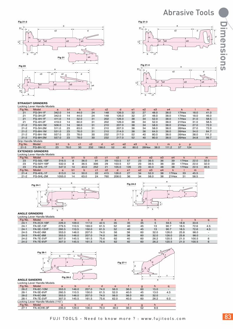
STRAIGHT GRINDERSLocking Lever Handle Models Fig No. Model a b1 b c1 c2 d e1 e2 e3 e4 k l m 21 FG-3H-1F 342.0 14 44.0 24 148 126.0 32 27 48.0 38.0 17Hex 18.0 41.0 21 FG-3H-2F 342.0 14 44.0 24 148 126.0 32 27 48.0 38.0 17Hex 18.0 46.0 21 FG-4H-1F 411.0 14 52.0 31 202 126.0 38 34 52.0 38.0 17Hex 31.0 58.5 21 FG-4H-2F 419.0 14 60.0 31 202 126.0 38 34 52.0 38.0 21Hex 31.0 58.5 21-2 FG-5H-1M 506.0 14 58.0 31 210 207.0 38 34 58.0 38.0 21Hex 27.0 72.0 21-2 FG-5H-2M 511.0 23 63.0 31 210 207.0 38 34 58.0 38.0 26Hex 27.0 72.0 21-2 FG-6H-1M 531.0 23 76.0 31 210 214.0 38 36 64.0 38.0 26Hex 34.0 84.7 21-2 FG-8H-1M 557.0 23 78.0 30 232 217.0 52 40 80.0 38.0 26Hex 38.0 111.2 21-2 FG-8H-2M 557.0 23 78.0 30 232 217.0 52 40 80.0 38.0 26Hex 34.8 99.7Grip Handle Models Fig No. Model b1 b c1 c2 d e1 e2 e3 k l m o p 21-3 FG-8H-1C 23 78.0 30 232 198.0 52 40 80.0 26Hex 38.0 111.2 57 124
Fig 21-2 Fig 21-3
e1 e2 e3 e4
a
c2 d
b
m
b1
c1
l
k e1 e2 e3
a
c2 d
b
m
b1
c1
o
p
l
k
Fig 21 e4
d
EXTENDED GRINDERSLocking Lever Handle Models Fig No. Model a b1 b c3 c1 c2 d e1 e2 e3 e4 k l m 23 FG-50L-1BF 316.5 8 36.0 91 29 103.5 57 23 39.5 36 39 17Hex 22.0 32.0 23 FG-50Y-1BF 532.0 8 36.5 306 29 103.5 57 23 39.5 36 39 17Hex 22.0 32.0 23 FG-3HL-1F 547.0 14 43.0 252 21 105.0 126 23 40.0 48 38 17Hex 22.5 40.5 Fig No. Model a b1 b c1 c2 d e1 e2 e3 e4 k l m 21-4 FG-4HL-1F 613.0 14 50.0 22 415 126.0 27 34 52.0 38 17Hex 33 45.5 21-2 FG-5HL-2M 1055.0 14 63.0 24 760 208.0 36 34 58.0 38 21Hex 31 58.5
Fig 23
e4e1 e2 e3m
l
k
a
b
c3 c2 d
b1
c1
Fig 21-4
e1 e2 e3 e4
a
c2 d
b
m
b1
c1
l
k
Fig 24-1a
b c
e
g
qd
i
h
k
j
f
ANGLE GRINDERSLocking Lever Handle Models Fig No. Model a b c d e f g h i j k q 24-1 FA-2CX-1BF 226.0 109.0 117.0 42.5 35 35 35 5 59.5 18.8 33.6 - 24-1 FA-5E-13F 279.5 110.5 169.0 61.5 52 40 45 13 90.7 18.5 72.6 4.5 24-1 FA-5E-13VF 260.5 110.5 150.0 61.5 52 40 45 13 90.7 18.5 72.6 4.5 24-3 FA-6C-9M 353.0 146.0 207.0 74.0 56 38 60 32.0 126.0 25.8 98.0 - 24-3 FA-6C-8M 353.0 146.0 207.0 74.0 56 38 60 32.0 126.0 25.8 98.0 - 24-2 FA-7E-5VF 307.0 145.5 161.5 75.6 62 40 60 26.2 120.5 21.0 100.5 6 24-2 FA-7E-6VF 307.0 145.5 161.5 75.6 62 40 60 26.2 120.5 21.0 100.5 6
Fig 24-2a
b c
e
g
qd
i
h
k
j
f
ANGLE SANDERSLocking Lever Handle Models Fig No. Model a b c d e f g h q 26-2 FA-6C-10M 353.0 146.0 207.0 74.0 56.0 38.0 60 15.0 - 26-1 FA-5E-6VF 260.5 110.5 150.0 61.5 52.0 40.0 45 13.0 4.5 26-2 FA-6C-9M 353.0 146.0 207.0 74.0 56.0 38.0 60 32.0 - 26-1 FA-7E-5VF 307.0 145.5 161.5 75.6 62.0 40.0 60 26.2 6.0Locking Lever Handle Models (110˚) Fig No. Model a b c d e f g h 27-1 FA-4CHK-3F 235.0 129.0 106.0 70.0 48.0 38.0 52 8.6
Fig 26-1 a
b c
qd
h
e
g
f
Fig 26-2
Fig 27-1
a
b c
d
e
h
f
g
f

Fig 29-2
Fig 29-3
DISC SANDER Fig No. Model a b c1 c2 e f g h 28 FG-5PX-1 108.0 21.0 24.0 63.0 50.0 25.0 41 147.0
VERTICAL GRINDERSStandard Type Fig No. Model a b c d e f g h i j k l 29-1 FV-7-1M 247.0 100.0 147.0 63.0 94.4 26.2 64 201.0 46 38 22.0 96.6 29-1 FV-7-4M 247.0 100.0 147.0 63.0 94.4 26.2 64 201.0 46 38 22.0 96.6 29-1 FV-9BH-1M 266.0 127.5 138.5 69.0 119.0 50.2 69 238.2 46 38 30.0 122.0Cup Wheel Type Fig No. Model a b c d e f g h i j l m 29-3 FV-9BH-4M 266.0 127.5 138.5 69.0 119.0 76 69 264.0 46 38 88.4 56~85Sanding DiscType Fig No. Model a b c d e f g i j 29-2 FV-7-2M 247.0 100.0 147.0 63.0 94.4 38 64 46 38
Fig 28
f h
a
b
c1
c2
e
g f
m
Fig 29-1
ab c
l
kf
eh
d
i jg
BELT SANDERS Fig No. Model a b c d e f g h i j 30 FBS-1-1 281 87 84 110 10 51 35 121 18 45.2 30 FBS-1-2 375 181 84 110 20 51 35 121 22 45.2 30 FBS-1-3 345 151 84 110 13 51 35 121 18 45.2 30 FBS-1-4 345 151 84 110 20 51 35 121 22 45.2
a
b c d
Fig 30
i
e
j
f
hg
bb
cc
ae
ae
Fig 31
d
Fig 32
d
gg
ORBITAL SANDERSLocking Lever Handle Models Fig No. Model a b c d e f g h 31 FOR-125BF-E(-M) 259 216 35 122 125 42 69 26 31 FOR-150BF-E(-M) 276 124 35 122 150 42 68 26 32 FOS-175BF-E(-M) 285 216 35 130 100X175 42 69 26 32 FOS-230BF-E 312 217 35 132 100X230 42 68 26 32 FOS-400BF-E 400 211 32 138 100X400 43 66 26
ff
hh
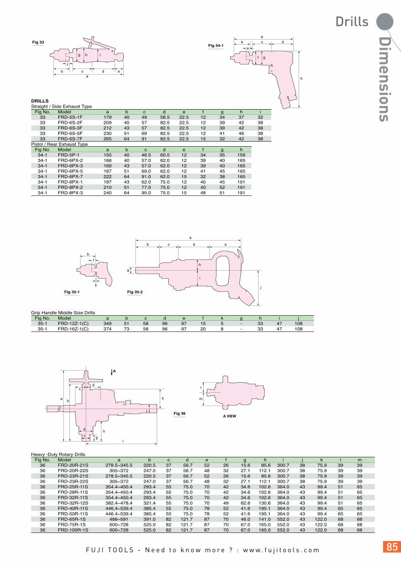
ab
b
c d
c d
e
f
DRILLSStraight / Side Exhaust Type Fig No. Model a b c d e f g h i 33 FRD-5S-1F 179 40 49 58.5 22.5 12 34 37 32 33 FRD-6S-2F 209 40 57 82.5 22.5 12 39 42 38 33 FRD-6S-3F 212 43 57 82.5 22.5 12 39 42 38 33 FRD-6S-5F 230 51 69 82.5 22.5 12 41 46 38 33 FRD-6S-7F 265 64 91 82.5 22.5 15 32 42 38Pistol / Rear Exhaust Type Fig No. Model a b c d e f g h 34-1 FRD-5P-1 155 40 46.5 60.5 12 34 35 159 34-1 FRD-6PX-2 166 40 57.0 62.0 12 39 40 165 34-1 FRD-6PX-3 169 43 57.0 62.0 12 39 40 165 34-1 FRD-6PX-5 187 51 69.0 62.0 12 41 45 165 34-1 FRD-6PX-7 222 64 91.0 62.0 15 32 38 165 34-1 FRD-8PX-1 187 43 62.0 75.0 12 40 45 191 34-1 FRD-8PX-2 210 51 77.0 75.0 12 40 52 191 34-1 FRD-8PX-3 240 64 95.0 75.0 15 48 51 191
Fig 33Fig 34-1
a
e
gf
h
h
gi
Grip Handle Middle Size Drills Fig No. Model a b c d e f k g h i j 35-1 FRD-12Z-1(C) 349 51 58 96 97 15 5 - 33 47 108 35-1 FRD-16Z-1(C) 374 73 58 96 97 20 8 - 33 47 108
edcb
Fig 35-2Fig 35-1
a
b
f
kj
h
i
g
Fig 36
i
l
mk
A
A VIEW
ab
j
g
h
cd
e
f
Heavy -Duty Rotary Drills Fig No. Model a b c d e f g h i j k l m 36 FRD-20R-21S 278.5~345.5 220.5 37 56.7 52 26 15.6 85.6 300.7 38 75.9 39 39 36 FRD-20R-22S 305~372 247.0 37 56.7 48 32 27.1 112.1 300.7 38 75.9 39 39 36 FRD-23R-21S 278.5~345.5 220.5 37 56.7 52 26 15.6 85.6 300.7 38 75.9 39 39 36 FRD-23R-22S 305~372 247.0 37 56.7 48 32 27.1 112.1 300.7 38 75.9 39 39 36 FRD-25R-11S 354.4~450.4 293.4 55 75.0 70 42 34.6 102.6 364.0 43 99.4 51 65 36 FRD-28R-11S 354.4~450.4 293.4 55 75.0 70 42 34.6 102.6 364.0 43 99.4 51 65 36 FRD-32R-11S 354.4~450.4 293.4 55 75.0 70 42 34.6 102.6 364.0 43 99.4 51 65 36 FRD-32R-12S 382.4~478.4 321.4 55 75.0 70 49 62.6 130.6 364.0 43 99.4 51 65 36 FRD-40R-11S 446.4~539.4 385.4 55 75.0 78 52 41.6 195.1 364.0 43 99.4 65 65 36 FRD-50R-11S 446.4~539.4 385.4 55 75.0 78 52 41.6 195.1 364.0 43 99.4 65 65 36 FRD-65R-1S 466~591 391.0 82 121.7 87 70 46.0 141.0 552.0 43 122.0 68 68 36 FRD-75R-1S 600~728 525.0 82 121.7 87 70 67.0 165.0 552.0 43 122.0 68 68 36 FRD-100R-1S 600~728 525.0 82 121.7 87 70 67.0 165.0 552.0 43 122.0 68 68

Fig 37 Fig 38
a
b
g hf
i o i j kg
e
qf
j l n
p
a
b
h
c d
n o p
m
l
BABY ANGLE DRILLS Fig No. Model a b f g h i j l n o p 37 FCD-6B-1(F) 222 99.5 10.5 26.5 19 16 21 34 32 19.6 9.5HexCORNER DRILLS Fig No. Model a b c d e f g h i j k l m 38 FCD-6X-1(F) 273 97 64 112 63 12 79 42 32 42 42 22.0 26.0 38 FCD-6X-2(F) 286 97 77 112 63 12 79 42 32 42 44 22.0 26.0 38 FCD-10X-1(F) 377 93 60 224 62 14 82 42 36 46 50 24.5 17.5
n o p q 12 15 54 40 12 15 54 43 82 10 84 51
Fig 39
ac
i
d
b
h
e f g
nml
ku
j
v
Heavy-Duty Corner Drills Fig No. Model a b c d e f g h i j k l m 39 F-14CN-1S 414 24 150 20 70 55 95 22 6.0 21.0 135.0~173.0 110.0 71.7 39 F-14CN-2S 414 24 150 20 70 55 93 29 16.5 33.5 147.5~185.5 122.5 71.7 39 F-22RCN-1S 499 35 150 39 79 50 146 29 8.0 24.0 177.0~237.0 152.0 88.0 39 F-32RCN-1S 529 40 175 39 79 50 146 34 11.0 21.0 195.0~255.0 170.0 88.0 39 F-32RCNS-1S 529 40 175 39 79 50 146 35 1.0 9.0 126.0~151.0 107.0 88.0 39 F-22RCR-1S 528 35 150 39 79 50 175 29 8.0 24.0 177.0~237.0 152.0 88.0 39 F-32RCR-1S 558 40 175 39 79 50 175 34 11.0 21.0 195.0~255.0 170.0 88.0 39 FCD-23R-11(S) 473 27 96 39 80 60 172 27 5.5 15.5 151.5~186.5 126.5 91.5 39 FCD-23R-12(S) 473 27 96 39 80 60 172 31 14.5 37.5 172.5~207.5 147.5 91.5 39 FCD-32R-11S 579 35 118 50 101 72 203 35 10.0 26.0 194.0~247.0 164.0 110.0 39 FCD-50R-11(S) 596 42 128 50 101 75 200 44 16.0 38.0 230.0~288.0 191.0 110.0 39 FCD-75R-11(S) 652 49 157 50 121 75 200 60 18.0 48.0 272.0~329.0 227.0 110.0 39 FCD-100R-11(S) 729 62 241 50 101 75 200 60 38.0 75.0 306.0~411.0 285.0 110.0
n u v 62 40 16 62 40 16 82 38 16 82 38 16 82 38 14 82 38 16 82 38 16 81 38 16 81 38 16 96 43 16 96 43 22.2 96 43 25.4 96 43 23
TAPPERS Fig No. Model a b c d e f g h j 34-1 FT-6P-1 236 45 112 63.5 15 38 45 154.0 - 34-1 FT-6BX-1D 206 40 34 128.0 15 46 47 143.5 - 34-2 FT-6BX-1T 241 75 34 128.0 15 46 47 143.5 32 34-2 FT-8PX-1 232 78 27 121.0 14 46 45 193.0 32
Fig 34-2Fig 34-1
b c da
e
f
h
g
be
j
b dc
Fig 41
FLUX CHIPPERS Fig No. Model a b c d e f g h 41 FCH-20-1F 176 66 52 58 33 32 36 9.0 41 FCH-20F-1F 182 42 82 58 39 32 36 12.7 41 FCH-25-1F 204 44 92 68 39 40 44 12.7 41 FCH-25B-1F 239 44 92 103 39 40 44 12.7
a
h
fe g
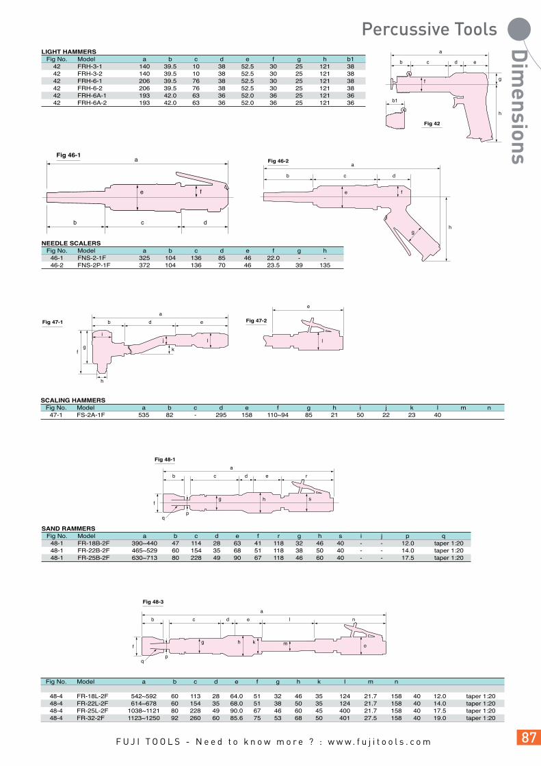
LIGHT HAMMERS Fig No. Model a b c d e f g h b1 42 FRH-3-1 140 39.5 10 38 52.5 30 25 121 38 42 FRH-3-2 140 39.5 10 38 52.5 30 25 121 38 42 FRH-6-1 206 39.5 76 38 52.5 30 25 121 38 42 FRH-6-2 206 39.5 76 38 52.5 30 25 121 38 42 FRH-6A-1 193 42.0 63 36 52.0 36 25 121 36 42 FRH-6A-2 193 42.0 63 36 52.0 36 25 121 36
d ecb
Fig 42
a
h
gf
b1
NEEDLE SCALERS Fig No. Model a b c d e f g h 46-1 FNS-2-1F 325 104 136 85 46 22.0 - - 46-2 FNS-2P-1F 372 104 136 70 46 23.5 39 135
Fig 46-1a
b
e f
c d
Fig 46-2
b c d
e
hg
f
a
SCALING HAMMERS Fig No. Model a b c d e f g h i j k l 47-1 FS-2A-1F 535 82 - 295 158 110~94 85 21 50 22 23 40 m n
Fig 47-1
fg k
h
a
b d e
ij l
Fig 47-2
e
l
SAND RAMMERS Fig No. Model a b c d e f r g h s i j 48-1 FR-18B-2F 390~440 47 114 28 63 41 118 32 46 40 - - 12.0 taper 1:20 48-1 FR-22B-2F 465~529 60 154 35 68 51 118 38 50 40 - - 14.0 taper 1:20 48-1 FR-25B-2F 630~713 80 228 49 90 67 118 46 60 40 - - 17.5 taper 1:20
p q
Fig 48-1
a
b c d e r
g s
pq
hf
Fig 48-3
a
b c d e l n
g k mhf
pq
o
Fig No. Model a b c d e f g h k l m n
48-4 FR-18L-2F 542~592 60 113 28 64.0 51 32 46 35 124 21.7 158 40 12.0 taper 1:20 48-4 FR-22L-2F 614~678 60 154 35 68.0 51 38 50 35 124 21.7 158 40 14.0 taper 1:20 48-4 FR-25L-2F 1038~1121 80 228 49 90.0 67 46 60 45 400 21.7 158 40 17.5 taper 1:20 48-4 FR-32-2F 1123~1250 92 260 60 85.6 75 53 68 50 401 27.5 158 40 19.0 taper 1:20

Fig 51
Fig 49-1
Fig 50-1 Fig 50-2 Fig 50-3
Fig 49-2
a
ji
b c
d t u
k
a1
g1
b1
nm
l
jk i r
o
s
c1c3
c4
e1f1
e1f1
h
a1 a2
g1 h
c2d
f2g2
AIR MOTORSReversible Type Fig No. Model a1 b1 c1 c3 c4 e1 e2 f1 g1 h i j k 49-1 F-5SM-8.5R 147 8 7.0 - - 10 - 12 20.0 5 40 60 74 49-1 F-5SM-2R 180 8 7.0 - - 10 - 12 25.0 5 40 60 74 49-1 F-6SM-28R 146 10 8.5 - - 12 - 14 19.0 6 42 70 88 49-1 F-6SM-21R 146 10 8.5 - - 12 - 14 19.0 6 42 70 88 49-1 F-6SM-12R 157 10 8.5 - - 12 - 14 18.0 6 42 70 88 49-1 F-6SM-8R 179 10 8.5 - - 12 - 14 36.0 6 42 70 88 49-1 F-6SM-5R 179 10 8.5 - - 12 - 14 36.0 6 42 70 88 49-1 F-6SM-2.5R 192 10 8.5 - - 12 - 14 36.0 6 42 70 88 49-2 F-8SM-28R 183 12 - 2.5 4.0 - 18 25 29.0 6 58 70 88 49-2 F-8SM-12R 199 12 - 2.5 4.0 - 18 25 49.0 8 58 90 114 49-2 F-8SM-8.5R 222 16 - 3.0 5.0 - 25 32 46.5 8 58 90 114
l m n o r s 55 33 35 18 6.5 8.0 55 33 35 18 6.5 8.0 64 38 39 20 6.5 8.0 64 38 38 20 6.5 8.0 64 38 39 20 6.5 8.0 64 38 39 20 6.5 8.0 64 38 38 20 6.5 8.0 64 38 38 20 6.5 8.0 64 38 45 26 11.0 17.0 81 48 52 26 11.0 17.0 81 48 51 26 11.0 17.0
Non-reversible Type Fig No. Model a1 b1 c1 c3 c4 e1 e2 f1 g1 h i j k 50-1 F-5SM-8.5 152 8 7.0 - - 10 - 12 20.0 5 32 60 74 50-1 F-5SM-2 185 8 7.0 - - 10 - 12 25.0 5 32 60 74 50-1, 3 F-6SM-28 167 10 8.5 - - 12 - 14 19.0 6 38 70 88 50-1, 3 F-6SM-21 167 10 8.5 - - 12 - 14 19.0 6 38 70 88 50-1, 3 F-6SM-12 178 10 8.5 - - 12 - 14 18.0 6 38 70 88 50-1, 3 F-6SM-8 200 10 8.5 - - 12 - 14 36.0 6 38 70 88 50-1, 3 F-6SM-5 200 10 8.5 - - 12 - 14 36.0 6 38 70 88 50-1, 3 F-6SM-2.5 213 10 8.5 - - 12 - 14 36.0 6 38 70 88 50-2, 3 F-8SMA-28 181 12 - 2.5 4.0 - 18 25 30.0 6 50 70 88 50-2, 3 F-8SMA-12 200 12 - 2.5 4.0 - 18 25 28.0 8 50 90 114 50-2, 3 F-8SMA-8.5 222 16 - 3.0 5.0 - 25 32 46.5 8 50 90 114
l m n a2 b2 c2 d f2 g2 55 33 35 - - - - - - 55 33 35 - - - - - - 64 38 39 169 3/8-24 10 4 12 21.0 64 38 39 167 3/8-24 10 4 12 19.0 64 38 41 178 3/8-24 10 4 12 18.0 64 38 38 200 3/8-24 14 5 12 36.0 64 38 38 200 3/8-24 14 5 12 36.0 64 38 38 214 3/8-24 14 5 12 36.0 64 38 43 173 3/8-24 12 5 12 20.0 81 48 51 189 3/8-24 12 5 12 17.0 81 48 51 208 1/2-20 14 6 15 32.5
m n o p q r s t u 30 38 40 42 - - - 16 2 30 38 40 44 46 44 - 16 2 30 38 40 44 42 - - 16 2 - - 53 54 54 54 54 17 5
Non-reversible Type Fig No. Model a b c d e f g1 g2 h i j k l 51 F-6SE 210 3/8-24 12 17 15.88 32 38 - - 38 52 176 26 52 F-6SF 225 3/8-24 12 17 15.88 32 38 - - 38 52 176 26 53 F-6PFX 184 3/8-24 12 17 15.88 32 - 44 170 38 52 176 26 54 F-10MT 266 1/2-20 16 22 19.05 38 - - 352 - - - -
b1 i
c1
e
b2
nm
l
jk
e2
e2
c3
c4
f
ml
n g1o p
Fig 52
c
a
d t u
e
b
g1f n o p rq
ji
k
mlFig 54
a
c
d t u
hb e
sof p rq
Fig 53
a
b e
c
d t u
f n o p q
g2ji
h
kl
m
Fig 55-1
df
c
b
a
eg
Fig 55-2
d
b
f
c
a
eg
Portable Type Fig No. Model a b c d e f g h 55-1 FM-2R-2C 630 19 40 24 100 60 132 55-2 FNR-20 506 16 17 20 62 31 95 55-2 FNR-20S 506 16 17 20 62 31 95 56 FM-14RK-101 473 13 16 16.5 80 27 133 158 56 FM-24RK-101 579 14 17 17.5 98 35 170 197 56 FM-24RK-201 596 19 20 25.0 122 42 197 227 56 FM-27RK-101 652 31 30 35.0 151 49 233 275
Fig 56
h
e
c
db
g
a
f

Stationary Type Fig No. Model a b c d e f g h i j k l m 57 FM-1R-5 273 150 135 80 55 80 120 70 140 20 50 40 3.0 57 FM-1R-12 273 150 135 80 55 80 120 70 140 20 50 40 3.0 57 FM-2R-5 375 180 200 125 75 75 150 70 100 28 60 55 4.0 57 FM-3R-3 395 180 209 140 75 75 150 70 117 28 60 55 4.0 57 FM-3R-5 395 180 209 140 75 75 150 70 117 28 60 55 4.0 57 FM-5R-2 435 210 245 145 100 100 180 90 250 28 60 55 4.0 57 FM-10R-2 570 240 266 155 95 95 200 130 315 35 80 60 4.5
n o p q r 5 125 100 15 12 5 125 100 15 12 7 102 100 18 14 7 102 100 18 14 7 102 100 18 14 7 250 120 18 14 10 316 170 20 18
ao p
i h
fe
Fig 57
b
g
rk
l
j
m
n
c
d
q
TIP DRESSER Fig No. Model a b c d e f g h i j 63 FTD-18-1 292 30 87 44 21.5 29 47 - - - 63 FTD-18A-1 307 30 83 44 22.0 26 46 30 147 54
Fig 63a
b
d
c
i
h
e
f g
j
Fig 68
H
L
L
T
T
W
W
d
a
b
c
Fig 69
e
f
d
a
b c
g e f
AIR FILES Fig No. Model a b c d e f g T W L H 68 FRF-4-1F 228 73 133.5 30 40 32 27 4 13 21 6
AIR SAWS Fig No. Model a b c d e f g T W L 68 FRF-4-2F 232 77 133.5 30 40 32 27 2 13 21 Fig No. Model a b c d e f 69 FRS-45 421 24 50 46 131 48
Fig 72
f
ab
c de
MARKING PEN Fig No. Model a b c d e f 72 G-400 147.5 76 19.5 17.5 2.15 1.5
Fig 73 Fig 74a
cb
d
a
b c
e
f
g
d
AIR CLEANERS Fig No. Model a b c d 73 AC-200F 145 27 34 153 Fig No. Model a b c d e f g 74 FJP-500 1020 248.5 32 32 38 38 121
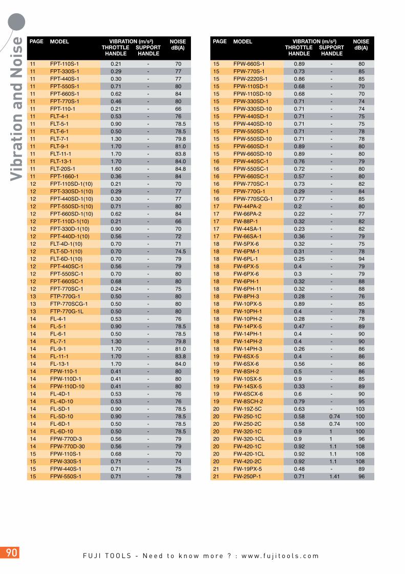
11 FPT-110S-1 0.21 - 70 11 FPT-330S-1 0.29 - 77 11 FPT-440S-1 0.30 - 77 11 FPT-550S-1 0.71 - 80 11 FPT-660S-1 0.62 - 84 11 FPT-770S-1 0.46 - 80 11 FPT-110-1 0.21 - 66 11 FLT-4-1 0.53 - 76 11 FLT-5-1 0.90 - 78.5 11 FLT-6-1 0.50 - 78.5 11 FLT-7-1 1.30 - 79.8 11 FLT-9-1 1.70 - 81.0 11 FLT-11-1 1.70 - 83.8 11 FLT-13-1 1.70 - 84.0 11 FLT-20S-1 1.60 - 84.8 11 FPT-1660-1 0.36 - 84 12 FPT-110SD-1(10) 0.21 - 70 12 FPT-330SD-1(10) 0.29 - 77 12 FPT-440SD-1(10) 0.30 - 77 12 FPT-550SD-1(10) 0.71 - 80 12 FPT-660SD-1(10) 0.62 - 84 12 FPT-110D-1(10) 0.21 - 66 12 FPT-330D-1(10) 0.90 - 70 12 FPT-440D-1(10) 0.56 - 72 12 FLT-4D-1(10) 0.70 - 71 12 FLT-5D-1(10) 0.70 - 74.5 12 FLT-6D-1(10) 0.70 - 79 12 FPT-440SC-1 0.56 - 79 12 FPT-550SC-1 0.70 - 80 12 FPT-660SC-1 0.68 - 80 12 FPT-770SC-1 0.24 - 75 13 FTP-770G-1 0.50 - 80 13 FTP-770SCG-1 0.50 - 80 13 FTP-770G-1L 0.50 - 80 14 FL-4-1 0.53 - 76 14 FL-5-1 0.90 - 78.5 14 FL-6-1 0.50 - 78.5 14 FL-7-1 1.30 - 79.8 14 FL-9-1 1.70 - 81.0 14 FL-11-1 1.70 - 83.8 14 FL-13-1 1.70 - 84.0 14 FPW-110-1 0.41 - 80 14 FPW-110D-1 0.41 - 80 14 FPW-110D-10 0.41 - 80 14 FL-4D-1 0.53 - 76 14 FL-4D-10 0.53 - 76 14 FL-5D-1 0.90 - 78.5 14 FL-5D-10 0.90 - 78.5 14 FL-6D-1 0.50 - 78.5 14 FL-6D-10 0.50 - 78.5 14 FPW-770D-3 0.56 - 79 14 FPW-770D-30 0.56 - 79 15 FPW-110S-1 0.68 - 70 15 FPW-330S-1 0.71 - 74 15 FPW-440S-1 0.71 - 75 15 FPW-550S-1 0.71 - 78
PAGE MODEL VIBRATION (m/s²)THROTTLE
HANDLESUPPORTHANDLE
NOISEdB(A)
15 FPW-660S-1 0.89 - 80 15 FPW-770S-1 0.73 - 85 15 FPW-2220S-1 0.86 - 85 15 FPW-110SD-1 0.68 - 70 15 FPW-110SD-10 0.68 - 70 15 FPW-330SD-1 0.71 - 74 15 FPW-330SD-10 0.71 - 74 15 FPW-440SD-1 0.71 - 75 15 FPW-440SD-10 0.71 - 75 15 FPW-550SD-1 0.71 - 78 15 FPW-550SD-10 0.71 - 78 15 FPW-660SD-1 0.89 - 80 15 FPW-660SD-10 0.89 - 80 16 FPW-440SC-1 0.76 - 79 16 FPW-550SC-1 0.72 - 80 16 FPW-660SC-1 0.57 - 80 16 FPW-770SC-1 0.73 - 82 16 FPW-770G-1 0.29 - 84 16 FPW-770SCG-1 0.77 - 85 17 FW-44PA-2 0.2 - 80 17 FW-66PA-2 0.22 - 77 17 FW-88P-1 0.32 - 82 17 FW-44SA-1 0.23 - 82 17 FW-66SA-1 0.36 - 79 18 FW-5PX-6 0.32 - 75 18 FW-6PM-1 0.31 - 78 18 FW-6PL-1 0.25 - 94 18 FW-6PX-5 0.4 - 79 18 FW-6PX-6 0.3 - 79 18 FW-6PH-1 0.32 - 88 18 FW-6PH-11 0.32 - 88 18 FW-8PH-3 0.28 - 76 18 FW-10PX-5 0.89 - 85 18 FW-10PH-1 0.4 - 78 18 FW-10PH-2 0.28 - 78 18 FW-14PX-5 0.47 - 89 18 FW-14PH-1 0.4 - 90 18 FW-14PH-2 0.4 - 90 18 FW-14PH-3 0.26 - 86 19 FW-6SX-5 0.4 - 86 19 FW-6SX-6 0.56 - 86 19 FW-8SH-2 0.5 - 86 19 FW-10SX-5 0.9 - 85 19 FW-14SX-5 0.33 - 89 19 FW-6SCX-6 0.6 - 90 19 FW-8SCH-2 0.79 - 95 20 FW-19Z-5C 0.63 - 103 20 FW-250-1C 0.58 0.74 100 20 FW-250-2C 0.58 0.74 100 20 FW-320-1C 0.9 1 100 20 FW-320-1CL 0.9 1 96 20 FW-420-1C 0.92 1.1 108 20 FW-420-1CL 0.92 1.1 108 20 FW-420-2C 0.92 1.1 108 21 FW-19PX-5 0.48 - 89 21 FW-250P-1 0.71 1.41 96
PAGE MODEL VIBRATION (m/s²)THROTTLE
HANDLESUPPORTHANDLE
NOISEdB(A)
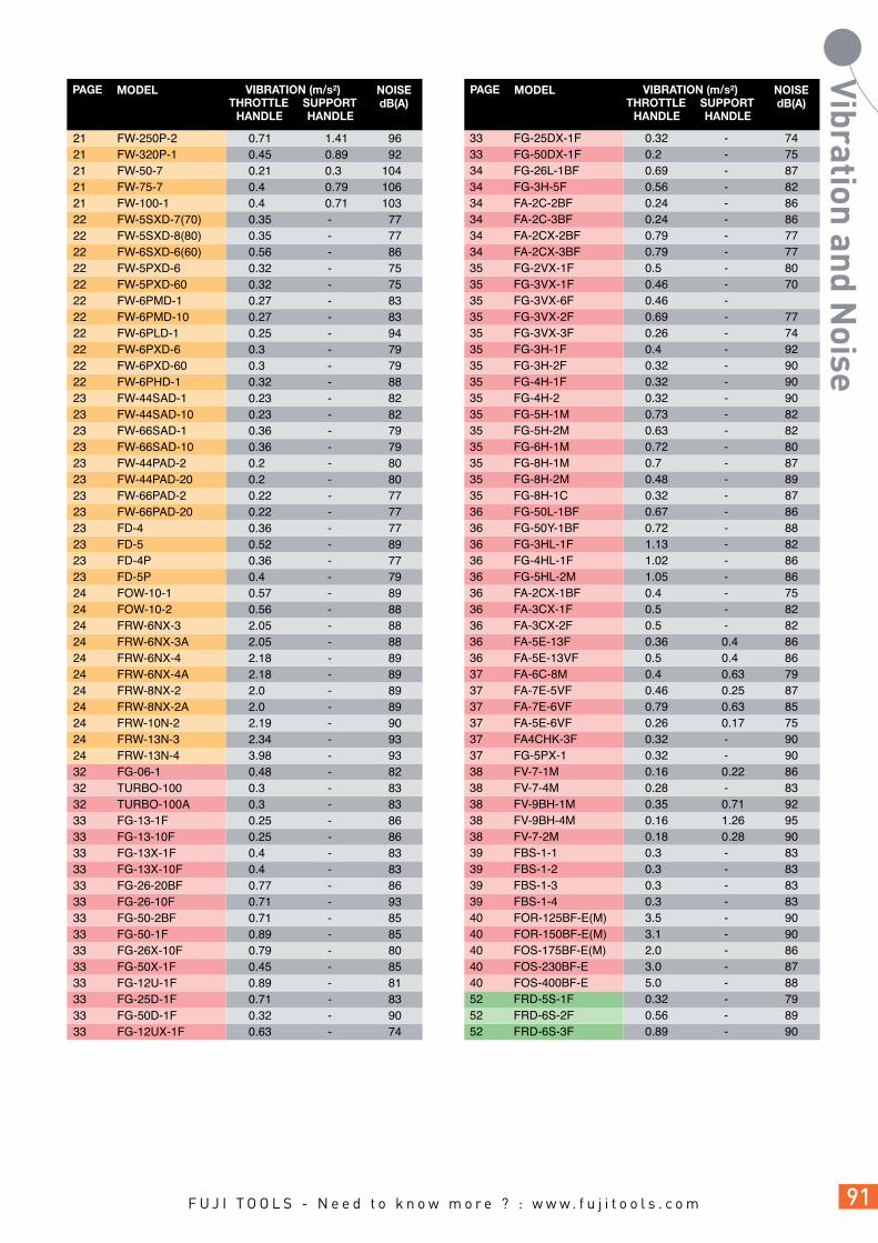
21 FW-250P-2 0.71 1.41 96 21 FW-320P-1 0.45 0.89 92 21 FW-50-7 0.21 0.3 104 21 FW-75-7 0.4 0.79 106 21 FW-100-1 0.4 0.71 103 22 FW-5SXD-7(70) 0.35 - 77 22 FW-5SXD-8(80) 0.35 - 77 22 FW-6SXD-6(60) 0.56 - 86 22 FW-5PXD-6 0.32 - 75 22 FW-5PXD-60 0.32 - 75 22 FW-6PMD-1 0.27 - 83 22 FW-6PMD-10 0.27 - 83 22 FW-6PLD-1 0.25 - 94 22 FW-6PXD-6 0.3 - 79 22 FW-6PXD-60 0.3 - 79 22 FW-6PHD-1 0.32 - 88 23 FW-44SAD-1 0.23 - 82 23 FW-44SAD-10 0.23 - 82 23 FW-66SAD-1 0.36 - 79 23 FW-66SAD-10 0.36 - 79 23 FW-44PAD-2 0.2 - 80 23 FW-44PAD-20 0.2 - 80 23 FW-66PAD-2 0.22 - 77 23 FW-66PAD-20 0.22 - 77 23 FD-4 0.36 - 77 23 FD-5 0.52 - 89 23 FD-4P 0.36 - 77 23 FD-5P 0.4 - 79 24 FOW-10-1 0.57 - 89 24 FOW-10-2 0.56 - 88 24 FRW-6NX-3 2.05 - 88 24 FRW-6NX-3A 2.05 - 88 24 FRW-6NX-4 2.18 - 89 24 FRW-6NX-4A 2.18 - 89 24 FRW-8NX-2 2.0 - 89 24 FRW-8NX-2A 2.0 - 89 24 FRW-10N-2 2.19 - 90 24 FRW-13N-3 2.34 - 93 24 FRW-13N-4 3.98 - 93 32 FG-06-1 0.48 - 82 32 TURBO-100 0.3 - 83 32 TURBO-100A 0.3 - 83 33 FG-13-1F 0.25 - 86 33 FG-13-10F 0.25 - 86 33 FG-13X-1F 0.4 - 83 33 FG-13X-10F 0.4 - 83 33 FG-26-20BF 0.77 - 86 33 FG-26-10F 0.71 - 93 33 FG-50-2BF 0.71 - 85 33 FG-50-1F 0.89 - 85 33 FG-26X-10F 0.79 - 80 33 FG-50X-1F 0.45 - 85 33 FG-12U-1F 0.89 - 81 33 FG-25D-1F 0.71 - 83 33 FG-50D-1F 0.32 - 90 33 FG-12UX-1F 0.63 - 74
33 FG-25DX-1F 0.32 - 74 33 FG-50DX-1F 0.2 - 75 34 FG-26L-1BF 0.69 - 87 34 FG-3H-5F 0.56 - 82 34 FA-2C-2BF 0.24 - 86 34 FA-2C-3BF 0.24 - 86 34 FA-2CX-2BF 0.79 - 77 34 FA-2CX-3BF 0.79 - 77 35 FG-2VX-1F 0.5 - 80 35 FG-3VX-1F 0.46 - 70 35 FG-3VX-6F 0.46 - 35 FG-3VX-2F 0.69 - 77 35 FG-3VX-3F 0.26 - 74 35 FG-3H-1F 0.4 - 92 35 FG-3H-2F 0.32 - 90 35 FG-4H-1F 0.32 - 90 35 FG-4H-2 0.32 - 90 35 FG-5H-1M 0.73 - 82 35 FG-5H-2M 0.63 - 82 35 FG-6H-1M 0.72 - 80 35 FG-8H-1M 0.7 - 87 35 FG-8H-2M 0.48 - 89 35 FG-8H-1C 0.32 - 87 36 FG-50L-1BF 0.67 - 86 36 FG-50Y-1BF 0.72 - 88 36 FG-3HL-1F 1.13 - 82 36 FG-4HL-1F 1.02 - 86 36 FG-5HL-2M 1.05 - 86 36 FA-2CX-1BF 0.4 - 75 36 FA-3CX-1F 0.5 - 82 36 FA-3CX-2F 0.5 - 82 36 FA-5E-13F 0.36 0.4 86 36 FA-5E-13VF 0.5 0.4 86 37 FA-6C-8M 0.4 0.63 79 37 FA-7E-5VF 0.46 0.25 87 37 FA-7E-6VF 0.79 0.63 85 37 FA-5E-6VF 0.26 0.17 75 37 FA4CHK-3F 0.32 - 90 37 FG-5PX-1 0.32 - 90 38 FV-7-1M 0.16 0.22 86 38 FV-7-4M 0.28 - 83 38 FV-9BH-1M 0.35 0.71 92 38 FV-9BH-4M 0.16 1.26 95 38 FV-7-2M 0.18 0.28 90 39 FBS-1-1 0.3 - 83 39 FBS-1-2 0.3 - 83 39 FBS-1-3 0.3 - 83 39 FBS-1-4 0.3 - 83 40 FOR-125BF-E(M) 3.5 - 90 40 FOR-150BF-E(M) 3.1 - 90 40 FOS-175BF-E(M) 2.0 - 86 40 FOS-230BF-E 3.0 - 87 40 FOS-400BF-E 5.0 - 88 52 FRD-5S-1F 0.32 - 79 52 FRD-6S-2F 0.56 - 89 52 FRD-6S-3F 0.89 - 90
PAGE MODEL VIBRATION (m/s²)THROTTLE
HANDLESUPPORTHANDLE
NOISEdB(A)
PAGE MODEL VIBRATION (m/s²)THROTTLE
HANDLESUPPORTHANDLE
NOISEdB(A)

52 FRD-6S-5F 0.79 - 86 52 FRD-6S-7F 0.56 0.4 88 52 FRD-5P-1 0.56 0.4 88 52 FRD-6PX-2 0.56 - 79 52 FRD-6PX-3 0.32 - 77 52 FRD-6PX-5 0.25 - 88 52 FRD-6PX-7 0.35 0.35 78 52 FRD-8PX-1 0.18 - 87 52 FRD-8PX-2 0.45 0.25 88 52 FRD-8PX-3 0.45 0.35 85 53 FRD-12Z-1C 0.32 - 96 53 FRD-16Z-1C 0.32 - 96 53 FRD-20R-21S 0.18 - 105 53 FRD-20R-22S 0.18 - 105 53 FRD-23R-21S 0.18 - 110 53 FRD-23R-22S 0.18 - 110 53 FRD-25R-11S 0.5 - 108 53 FRD-28R-11S 0.22 - 110 53 FRD-32R-11S 0.32 - 109 53 FRD-32R-12S 0.32 - 109 53 FRD-40R-11S 0.25 - 110 53 FRD-50R-11S 0.57 - 107 53 FRD-65R-1S 0.45 - 103 53 FRD-75R-1S 0.56 - 106 53 FRD-100R-1S 0.5 - 103 54 FCD-6B-1F 0.5 - 81 54 FCD-6X-1F 0.5 - 81 54 FCD-6X-2F 0.32 - 81 54 FCD-10X-1F 0.32 - 86 55 F-14CN-1S 0.28 - 100 55 F-14CN-2S 0.32 - 100 55 F-22RCN-1S 0.4 - 103 55 F-32RCN-1S 0.32 - 105 55 F-32RCNS-1S 0.56 - 104 56 F-22RCR-1S 0.32 - 101 56 F-32RCR-1S 0.32 - 102 56 FCD-23R-11S 0.2 - 105 56 FCD-23R-12S 0.2 - 105 56 FCD-32R-11S 0.18 - 108 56 FCD-50R-11S 0.22 - 110 56 FCD-75R-11S 0.2 - 101 56 FCD-100R-11S 0.32 - 107 58 FT-6P-1 0.45 - 87 58 FT-6BX-1 0.45 - 74 58 FT-8PX-1 0.45 - 89 62 FCH-20-1F 15.54 - 93 62 FCH-20F-1F 12.6 - 101 62 FCH-25-1F 31.6 - 83 62 FCH-25B-1F 31.6 - 83 62 FRH-3-1 7.32 - 99 62 FRH-3-2 7.32 - 99 62 FRH-6-1 6.22 - 97 62 FRH-6-2 6.22 - 97 62 FRH-6A-1 19.88 - 103 62 FRH-6A-2 19.88 - 103 62 FNS-2-1F (NEEDLE_3) 13.09 - 100
62 FNS-2P-1F (NEEDLE_3) 13.46 - 102 63 FS-2A-1F 11.96 - 103 63 FR-18B-2F 14.8 - 99 63 FR-22B-2F 26.22 - 98 63 FR-25B-2F 5.01 - 96 63 FR-18L-2F 3.16 - 96 63 FR-22L-2F 5.01 - 92 63 FR-25L-2F 5.01 - 96 63 FR-32-2F 5.62 - 99 70 G400 1.4 - 78
PAGE MODEL VIBRATION (m/s²)THROTTLE
HANDLESUPPORTHANDLE
NOISEdB(A)
PAGE MODEL VIBRATION (m/s²) THROTTLE
HANDLESUPPORTHANDLE
NOISEdB(A)

MODEL PAGE MODEL PAGE MODEL PAGE AC-200F 74 CA-14A 19 F-10MT 69 F-14CN-1S 55 F-14CN-2S 55 F-22RCN-1S 55 F-22RCR-1S 55 F-32RCN-1S 55 F-32RCNS-1S 55 F-32RCR-1S 55 F-5SM-2 68 F-5SM-2R 68 F-5SM-8.5 68 F-5SM-8.5R 68 F-6PFX 69 F-6SE 69 F-6SF 69 F-6SM-12 68 F-6SM-12R 68 F-6SM-2.5 68 F-6SM-2.5R 68 F-6SM-21 68 F-6SM-21R 68 F-6SM-28 68 F-6SM-28R 68 F-6SM-5 68 F-6SM-5R 68 F-6SM-8 68 F-6SM-8R 68 F-8SM-12R 68 F-8SM-28R 68 F-8SM-8.5R 68 F-8SMA-12 68 F-8SMA-28 68 F-8SMA-8.5 6 FA-2C-2BF 34 FA-2C-3BF 34 FA-2CX-1BF 36 FA-2CX-2BF 34 FA-2CX-3BF 34 FA-3CX-1F 36 FA-3CX-2F 36 FA-4CHK-3F 37 FA-5E-13F 36 FA-5E-13VF 36 FA-5E-6VF 37 FA-6C-8M 37 FA-6C-9M 37 FA-7E-5VF 37 FA-7E-6(8)V F 37 FBS-1-1 39 FBS-1-2 39 FBS-1-3 39 FBS-1-4 39 FCD-100R-11S 55 FCD-10X-1F 54 FCD-23R-11S 55 FCD-23R-12S 55 FCD-32R-11S 55 FCD-50R-11S 55 FCD-6B-1F 54 FCD-6X-1F 54 FCD-6X-2F 54 FCD-75R-11S 55 FCH-20-1F 62 FCH-20F-1F 62 FCH-25-1F 62
FCH-25B-1F 62 FD-4 23 FD-4P 23 FD-5 23 FD-5P 23 FG-06-1 32 FG-12U-1F 33 FG-12UX-1F 33 FG-13-1F 33 FG-13-10F 33 FG-13X-1F 33 FG-13X-10F 33 FG-25D-1F 33 FG-25DX-1F 33 FG-26-10F 33 FG-26-20BF 33 FG-26L-1BF 34 FG-26X-10F 33 FG-2VX-1F 35 FG-3H-1F 35 FG-3H-2F 35 FG-3H-5F 34 FG-3HL-1F 36 FG-3VX-1F 35 FG-3VX-2F 35 FG-3VX-3F 35 FG-3VX-6F 35 FG-4H-1F 35 FG-4H-2F 35 FG-4HL-1F 36 FG-50-1F 33 FG-50-2BF 33 FG-50D-1F 33 FG-50DX-1F 33 FG-50L-1BF 36 FG-50X-1F 33 FG-50Y-1BF 36 FG-5H-1M 35 FG-5H-2M 35 FG-5HL-2M 36 FG-5PX-1 37 FG6H-1M 35 FG8H-1C 35 FG-8H-1M 35 FG-8H-2M 35 FJP-500 74 FM-10R-2 70 FM-14RK-101 69 FM-1R-12 70 FM-1R-5 70 FM-24RK-101 69 FM-24RK-201 69 FM-27RK-101 69 FM-2R-2C 68 FM-2R-5 70 FM-3R-3 70 FM-3R-5 70 FM-5R-2 70 FNR-20 69 FNR-20S 69 FNS-2-1F 62 FNS-2P-1F 62 FOR-125BF-E (M) 40 FOR-150BF-E (M) 40 FOS-175BF-E (M) 40 FOS-230BF-E 40 FOS-400BF-E 40
FOW-10-1 25 FOW-10-2 25 FPT-110-1 11 FPT-110D-1 12 FPT-110D-10 12 FPT-110S-1 11 FPT-110SD-1 12 FPT-110SD-10 12 FL-4-1 14 FL-5-1 14 FL-6-1 14 FL-7-1 14 FL-9-1 14 FL-11-1 14 FL-13-1 14 FL-4D-1 14 FL-4D-10 14 FL-5D-1 14 FL-5D-10 14 FL-6D-1 14 FL-6D-10 14 FLT-4-1 11 FLT-4D-1 12 FLT-4D-10 12 FLT-5D-1 12 FLT-5D-10 12 FLT-5-1 11 FLT-6-1 11 FLT-6D-1 12 FLT-6D-10 12 FLT-7-1 11 FPT-1660-1 11 FLT-9-1 11 FPT-330 12 FPT-330S-1 11 FPT-330SD-1 12 FPT-330SD-10 12 FLT-11-1 11 FLT-13-1 11 FPT-440D-1 12 FPT-440D-10 12 FPT-440S-1 11 FPT-440SC-1 12 FPT-440SD-1 12 FPT-440SD-10 12 FLT-20S-1 11 FPT-550S-1 11 FPT-550SC-1 12 FPT-550SD-1 12 FPT-550SD-10 12 FPT-660SD-1 12 FPT-660SD-10 12 FPT-660S-1 11 FPT-660SC-1 12 FPT-770S-1 11 FPT-770SC-1 12 FPT-770SCG-1 13 FPW-110-1 14 FPW-110D-1 14 FPW-110D-10 14 FPW-110S-1 15 FPW-110SD-1 15 FPW-110SD-10 15 FPW-1660-1 14 FPW-2220S-1 15 FPW-330S-1 15 FPW-330SD-1 15

MODEL PAGE MODEL PAGE MODEL PAGE FPW-330SD-10 15 FPW-440S-1 15 FPW-440SC-1 16 FPW-440SD-1 15 FPW-440SD-10 15 FPW-550S-1 15 FPW-550SC-1 16 FPW-550SD-1 15 FPW-550SD-10 15 FPW-660S-1 15 FPW-660SC-1 16 FPW-660SD-1 15 FPW-660SD-10 15 FPW-770G-1 16 FPW-770S-1 15 FPW-770SC-1 16 FPW-770SCG-1 16 FR-18B-2F 63 FR-18L-2F 63 FR-22B-2F 63 FR-22L-2F 63 FR-25B-2F 63 FR-25L-2F 63 FR-32-2F 63 FRD-100R-1S 53 FRD-12Z-1C 53 FRD-16Z-1C 53 FRD-20R-21S 53 FRD-20R-22S 53 FRD-23R-21S 53 FRD-23R-22S 53 FRD-25R-11S 53 FRD-28R-11S 53 FRD-32R-11S 53 FRD-32R-12S 53 FRD-40R-11S 53 FRD-50R-11S 53 FRD-5P-1 52 FRD-5S-1F 52 FRD-5S-2T, 2TF 52 FRD-65R-1S 53 FRD-6PX-2 52 FRD-6PX-3 52 FRD-6PX-5 52 FRD-6PX-7 52 FRD-6S-2F 52 FRD-6S-3F 52 FRD-6S-5F 52 FRD-6S-7F 52 FRD-75R-1S 53 FRD-8PX-1 52 FRD-8PX-2 52 FRD-8PX-3 52 FRF-4-1F 73 FRF-4-2F 73 FRH-3-1 62 FRH-3-2 62 FRH-6-1 62 FRH-6-2 62 FRH-6A-1 62 FRH-6A-2 62 FRS-45 73 FRW-10N-2 24 FRW-13N-3 24 FRW-13N-4 24 FRW-6NX-3 24 FRW-6NX-3A 24
FRW-6NX-4 24 FRW-6NX-4A 24 FRW-8NX-2 24 FRW-8NX-2A 24 FS-2A-1F 63 FT-6BX-1 D 58 FT-6BX-1 T 58 FT-6P-1 58 FT-8PX-1 58 FTD-18-1 72 FTD-18A-1 72 FV-7-1M 38 FV-7-2M 38 FV-7-4M 38 FV-9BH-1M 38 FV-9BH-4M 38 FVT-1 8 FW-100-1 21 FW-10PH-1 18 FW-10PH-2 18 FW-10PX-5 18 FW-10SX-5 19 FW-14PH-1 18 FW-14PH-2 18 FW-14PH-3 18 FW-14PX-5 18 FW-14SX-5 19 FW-19PX-5 21 FW-19Z-5C 20 FW-250-1C 20 FW-250-2C 20 FW-250P-1 21 FW-250P-2 21 FW-320-1C 20 FW-320-1CL 20 FW-320P-1 21 FW-420-1C 20 FW-420-1CL 20 FW-420-2C 20 FW-44PA-2 17 FW-44PAD-2 23 FW-44PAD-20 23 FW-44SA-1 17 FW-44SAD-1 23 FW-44SAD-10 23 FW-50-7 21 FW-5PX-6 18 FW-5PXD-6 22 FW-5PXD-60 22 FW-5SXD-7 22 FW-5SXD-70 22 FW-5SXD-8 22 FW-5SXD-80 22 FW-66PA-2 17 FW-66PAD-2 23 FW-66PAD-20 23 FW-66SA-1 17 FW-66SAD-1 23 FW-66SAD-10 23 FW-6PH-1 18 FW-6PH-11 18 FW-6PHD-1 22 FW-6PL-1 18 FW-6PLD-1 22 FW-6PM-1 18 FW-6PMD-1 22 FW-6PMD-10 22
FW-6PX-5 18 FW-6PX-6 18 FW-6PXD-6 22 FW-6PXD-60 22 FW-6SCX-6 19 FW-6SX-5 19 FW-6SX-6 19 FW-6SXD-6 22 FW-6SXD-60 22 FW-75-7 21 FW-88P-1 17 FW-8PH-3 18 FW-8SCH-2 19 FW-8SH-2 19 G-400 74 TURBO-100 32 TURBO-100A 32


Power and Precision in Perfect harmony
Industrial tools from Fuji