power aware mobile displays ali iranli wonbok lee massoud pedram july 26, 2006 department of...
TRANSCRIPT


Power Aware Mobile Displays
Ali IranliWonbok Lee
Massoud Pedram
July 26, 2006
Department of Electrical EngineeringUniversity of Southern California

Outline
Display Systems and LCD Architecture Review of Dynamic Backlight Scaling Previous Work in Backlight Scaling Temporally Aware Backlight Scaling Implementation Experimental Results Conclusions & Future directions
LCD Architecture
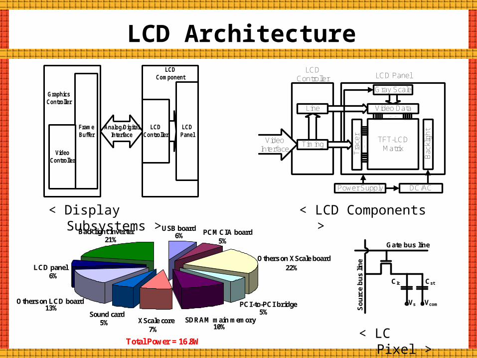
< Display Subsystems >
FrameBuffer
VideoController
GraphicsController
Analog/DigitalInterface
LCDPanel
LCDController
LCD Component
Gray Scale
Video Data
TFT-LCDMatrix
Tra
cer
Bac
klig
ht
…..
Power Supply DC/AC
LCDController LCD Panel
…..Video
InterfaceTiming
Line
Gate bus line
VcomVs
So
urc
e b
us
lin
e
CstCIc
Sound card
Others on LCD board
LCD panel
Backlight inverter USB board PCMCIA board
Others on XScale board
PCI-to-PCI bridge
SDRAM main memoryXScale core
6%21%
6%
13%
5%7% 10%
5%
22%
5%
Total Power = 16.8W
< LCD Components >
< LC Pixel >

Review of Backlight Scaling
Perceived light emitted from an LCD panel is a function of two parameters
Light intensity of the backlight Transmittance of the LCD panel
Two important observations: We can have the same perception of an image by using different
value assignments to the aforesaid parameters Power consumption of the BackLight Unit (BLU) is orders of
magnitude larger than the power consumption of the LCD panel
Backlight Scaling Idea: Dynamically dim the backlight while adjusting the transmittance of the LCD pixels such that the perceived luminance is preserved, yet the overall power consumption is reduced.
There is a trade off between the degree of image distortion and the amount of power saving

Precise Problem Statement
Dynamic Backlight Scaling Problem: Given the original image and the maximum tolerable image distortion , find the backlight scaling factor and the corresponding pixel transformation function
such that is minimized and
maxD
' ( , ) ( ', )P ( , ')D maxD
Let and '= (, ) denote the original and the transformed image data after backlight scaling, respectively
Moreover, let D(, ') and P(', ) denote the distortion of the images and ' and the power consumption of the LCD subsystem while displaying image ' with backlight scaling factor of
( ) ( )L x b t x
Perceived Luminance (L(x)) of a pixel is represented by:
: Grayscale level of a pixel (8 bits) : Transmittance of a pixel : Normalized backlight illumination factor
[0 : 255]x
[0,1]b( )t x

Prior Work
Dynamic backlight Luminance Scaling (DLS): Chang et al. in 2004 proposed a backlight scaling scheme based on two mechanisms: Grayscale Shifting: concentrate on the brightness loss compensation Grayscale Spreading: concentrate on the contrast enhancement
( , ) min(1, )x
x
( , ) min(1, (1 ))x x
: Pixel transformation function : Normalized pixel value in 8 bits color depth : Backlight scaling factor
x( , )x
255input grayscale
output grayscale
255identity transformation functionscaled transformation function
input grayscale
output grayscale
255
255identity transformation functionscaled transformation function
< Grayscale Shifting > < Grayscale Spreading >

Prior Work (Cont’d)
Concurrent Brightness and Contrast Scaling (CBCS): Cheng et al. in 2004 proposed two-sided single band grayscale spreading technique in the backlight scaling domain Truncate the image histogram in both ends to obtain a smaller
dynamic range and spread out the pixel values within this range Maintain the contrast fidelity and aggressively saves power
10, 0
( , ) ,
1, 1
lu l
l ul
uu l
cgg g
x cx d g x g whereg
dg xg g
input grayscale
output grayscale
255
255
lg ug
Pros: Eliminate the pixel-by-pixel transformation of the displayed image in DLS approach through the change of built-in LCD reference driver

Prior Work (Cont’d)
Histogram Equalization in Backlight Scaling (HEBS): Iranli et al. in 2005 proposed a non-linear grayscale spreading technique Present global histogram equalization algorithm to preserve visual
information in spite of image transformation
1
0( ( )) ( )U x H x dx
: Original cumulative histogram of an image : Cumulative uniform histogram of an image : Monotonic pixel transformation function
( )H x( )U x( )x
1
input pixel value
output pixel value
1
Histogram Equalization Problem: Find the monotonic transformation function that minimizes the above formula
Need modification in the built-in LCD reference driver to produce piece-wise linear image transformation function
Temporally-Aware Backlit Scaling (TABS)
Original Movie Sequence Modified Movie Sequence
Spatial distortion
Temporal distortion
Frame #1
Frame #2
Frame #3
Frame #N
Dark pixelBright pixel
Original Sequence Modified Sequence #1 Modified Sequence #2
time time time
0
0
0
0
0
00
+10
+10
+10
+10
-10
-10
-10
+10
+10
+10
+10
-10
-10
-10
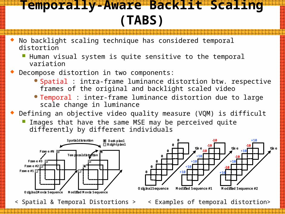
< Spatial & Temporal Distortions > < Examples of temporal distortion>
No backlight scaling technique has considered temporal distortion Human visual system is quite sensitive to the temporal variation
Decompose distortion in two components:Spatial : intra-frame luminance distortion btw. respective frames
of the original and backlight scaled videoTemporal : inter-frame luminance distortion due to large scale
change in luminance Defining an objective video quality measure (VQM) is difficult
Images that have the same MSE may be perceived quite differently by different individuals

Temporal Response Models Two models of the dynamics of light perception in temporal domain
Aperiodic stimuli: Measure the impulse response of human visual system (HVS)
Periodic stimuli: Measure the critical fusion frequency (CFF) at various amplitude
sensitivity (AS) valuesCFF: Minimum frequency above which an observer cannot detect
flickering effect when a series of light flashes at that frequency is presented to him/her
We adopt a computational temporal response model of HVS due to Weigand et al. proposed in 1995, which can be used to determine the AS threshold
< Temporal Response Model of the HVS >
ControlLow-Pass
filter
QuadraticLow-Pass
filter
QuadraticLow-Pass
filter
Parameter Extraction
XInput Light intensity Perceived
Light Brightness
rc(t)
f1, d1 f2, d2 gV(X(t))
X(t)
Luminance
Brightness
Static Spatial HVS Characteristic

Spatial and Temporal Distortions Two types of distortions:
Spatial:Upper bounded by user-given maximum value
Temporal: Not given but captures flickering, i.e., time-varying luminanceMSE between spectral power density of brightness
( , ') ( , ') (1 ) ( , ')spatial temporalD x x D x x D x x 2
'2
( { ( )} { ( ')} )
max( ( , )) (1 )( { ( )} )
j jj
spatial i ii
jj
F V x F V x
D x xF V x
: Original and backlight scaled video sequences, respectively : Spatial distortion between respective frames in two video : Temporal distortion in some consecutive frames : Perceived brightness : Weighting factor : Fourier transform operator
( , ')spatialD x x( , ')temporalD x x( )V x{}F
, 'x x

Distortions (Cont’d)
Spatial distortion is in time domain Temporal distortion is in frequency domain: Use Parseval’s theorem
Integral of squared signal equals integral of its spectral power density
1. For each video frame at time t, calculate the mean brightness value of all pixels, ,
2. Filter signals , using temporal response model to get perceived luminance signals
3. Calculate 4. Using above, modify
the maximum allowed spatial distortion,
( )X t ( )Y t
( )X t ( )Y t
( , )tmpD x y
( , )tmpD x y
< TABS Model >
Frame-by-FrameBacklight Scaling
Temporal Model of
HVS
-
AmplitudeSensitivity
Comparator
Input Video SequenceMaximumDistortion
Level
Output Video Sequence
Temporal Model of
HVSDtmp
maxDspt
TABS approach: Measure the temporal distortion of backlight scaled video and utilize this information to change the maximum allowed spatial distortion of frames < TABS Algorithm >
maxsptD
Implementation
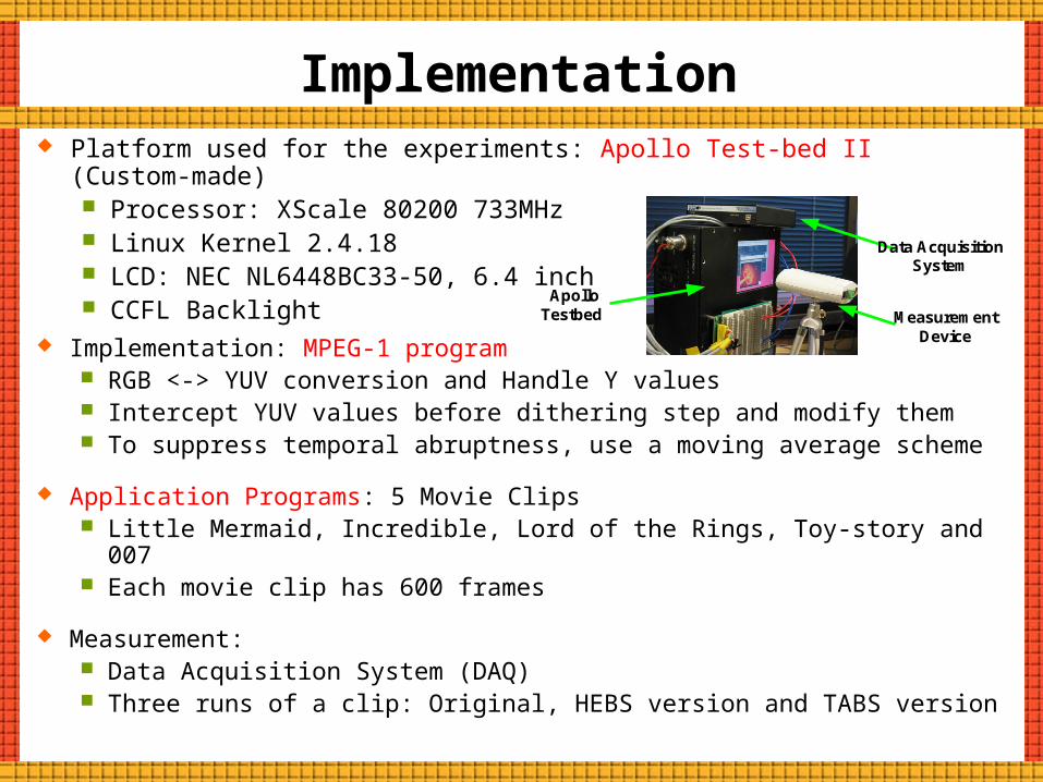
Implementation: MPEG-1 program RGB <-> YUV conversion and Handle Y values Intercept YUV values before dithering step and modify them To suppress temporal abruptness, use a moving average scheme
Application Programs: 5 Movie Clips Little Mermaid, Incredible, Lord of the Rings, Toy-story and 007 Each movie clip has 600 frames
Measurement: Data Acquisition System (DAQ) Three runs of a clip: Original, HEBS version and TABS version
Platform used for the experiments: Apollo Test-bed II (Custom-made) Processor: XScale 80200 733MHz Linux Kernel 2.4.18 LCD: NEC NL6448BC33-50, 6.4 inch CCFL Backlight
Data AcquisitionSystem
Measurement Device
ApolloTestbed

Experimental Results Backlight luminance changes
Time (frame #)
Bac
klig
ht lu
min
ance
(%)
0 10 20 30 40 50 60 70 80 90 1000.4
45
0.5
55
0.6
65
40
45
50
55
60
65
HEBSTABS
0
Flickering in HEBS occurs due to abrupt and frequent changes in the backlight intensity
To avoid this flickering, HEBS should be changed such that luminance changes are suppressed and smoothed out

Nor
mal
ized
Am
plitu
de
Frequency (Hz)0 7.5 15 22.5 30 22.5 15 7.5 0
0.125
0.250
0.375
0.500
0.625
0.750
0.875
1.000
Original Video5% max. Dist.15% max. Dist.
Nor
mal
ized
Am
plitu
de
Frequency (Hz)0 7.5 15 22.5 30 22.5 15 7.5 0
0.125
0.250
0.375
0.500
0.625
0.750
0.875
1.000
Original Video5% max. Dist.15% max. Dist.
0 7.5 15 22.5 30 22.5 15 7.5 0
0.125
0.250
0.375
0.500
0.625
0.750
0.875
1.000
No
rmal
ized
Am
plit
ud
e
Frequency (Hz)
Original Video5% max. Dist.15% max. Dist.
0 7.5 15 22.5 30 22.5 15 7.5 0
0.125
0.250
0.375
0.500
0.625
0.750
0.875
1.000
No
rmal
ized
Am
plit
ud
e
Frequency (Hz)
Original Video5% max. Dist.15% max. Dist.
< A little mermaid >
< The Incredibles >
Experimental Results (Cont’d)

Experimental Results (Cont’d)
0.0
5.0
10.0
15.0
20.0
25.0
30.0
En
erg
y S
av
ing
s (
%)
Mermaid Incredible Spongebob Toystory 00_7
5% distortion 10% distortion 15% distortion
< Energy Savings in TABS >
Energy Savings with human visual system awareness Savings become smaller when distortion goes up
Experimental Results (Cont’d)
0
5
10
15
20
25
En
erg
y S
av
ing
s (
%)
mermaid incredible spongebob toystory 00_7
HEBS TABS
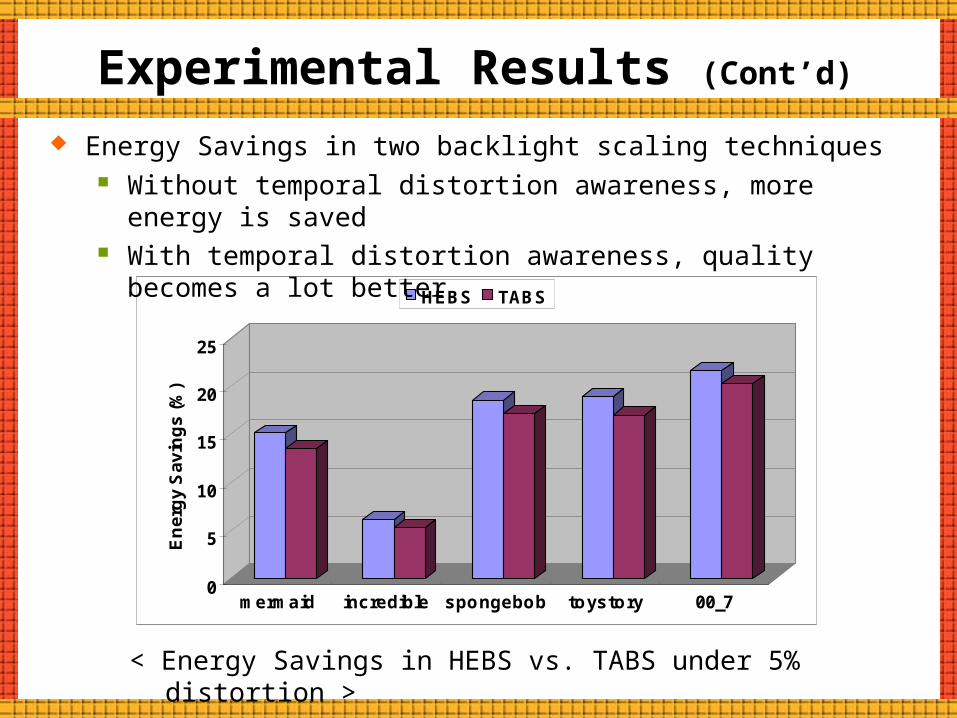
< Energy Savings in HEBS vs. TABS under 5% distortion >
Energy Savings in two backlight scaling techniques Without temporal distortion awareness, more energy is saved With temporal distortion awareness, quality becomes a lot better

Experimental Results (Cont’d)
Sound card
Others on LCD board
LCD panel
Backlight inverter USB board PCMCIA board
Others on XScale board
PCI-to-PCI bridge
SDRAM main memoryXScale core
6%21%
6%
13%
5%7% 10%
5%
22%
5%
Total Power = 16.8W
Backlight inverter15%
LCD panel6%
Others on LCD board13% Sound card
5%XScale core
7%SDRAM main memory
10%
PCI-to-PCI bridge5%
Others on XScale board22%
PCMCIA board5%
USB board6%
Reduction6%
Total Power = 15.8W
< Before >
< After >
System-wide Power Savings with 5% distortion in Apollo Test-bed II

Conclusions and Future Directions
For backlight scaling technique in video, consideration of both spatial and temporal distortion are quite important to video quality
Consideration of temporal distortion as well as spatial distortion lead to less energy savings (compared to the spatial distortion only method), but it achieve high quality gains. Simulation results show that 15 ~ 25% of energy savings are achieved in display systems with almost negligible perceivable flickering
Future Work: Manage the color shift problem in backlight scaling Account for the effect of ambient light on backlight scaling Consider other types of display technology
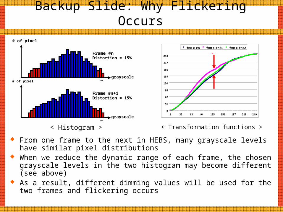
Backup Slide: Why Flickering Occurs
From one frame to the next in HEBS, many grayscale levels have similar pixel distributions
When we reduce the dynamic range of each frame, the chosen grayscale levels in the two histogram may become different (see above)
As a result, different dimming values will be used for the two frames and flickering occurs
grayscale
grayscale
# of pixel
# of pixel
Frame #n
Frame #n+1
255
255
< Histogram > < Transformation functions >
Distortion = 15%
Distortion = 15%
0
31
62
93
124
155
186
217
248
1 32 63 94 125 156 187 218 249
frame #n frame #n+1 frame #n+2