power connections
TRANSCRIPT
8/3/2019 Power Connections
http://slidepdf.com/reader/full/power-connections 1/22
Schneider Electric37 Assembly and installation guide
5
Version 3.0
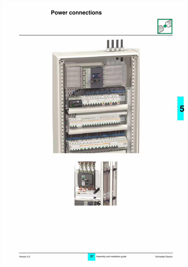
Power connections
8/3/2019 Power Connections
http://slidepdf.com/reader/full/power-connections 2/22
38 Schneider ElectricAssembly and installation guideVersion 3.0
Connecting the power devices
Electricalconnections offunctionalunits
Practical rules Examples for Prisma Plus
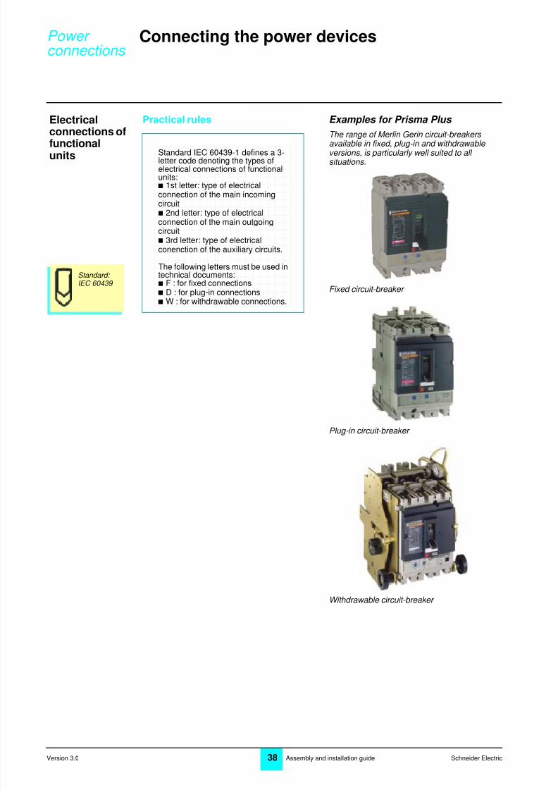
The range of Merlin Gerin circuit-breakers available in fixed, plug-in and withdrawable versions, is particularly well suited to all situations.
Fixed circuit-breaker
Plug-in circuit-breaker
Withdrawable circuit-breaker
Standard: IEC 60439
Standard IEC 60439-1 defines a 3-letter code denoting the types ofelectrical connections of functionalunits:b 1st letter: type of electricalconnection of the main incomingcircuitb 2nd letter: type of electricalconnection of the main outgoingcircuitb 3rd letter: type of electricalconenction of the auxiliary circuits.
The following letters must be used in
technical documents:b F : for fixed connectionsb D : for plug-in connectionsb W : for withdrawable connections.
Power connections
8/3/2019 Power Connections
http://slidepdf.com/reader/full/power-connections 3/22
Schneider Electric39 Assembly and installation guide
5
Version 3.0
Principle Practical rules Examples for Prisma Plus
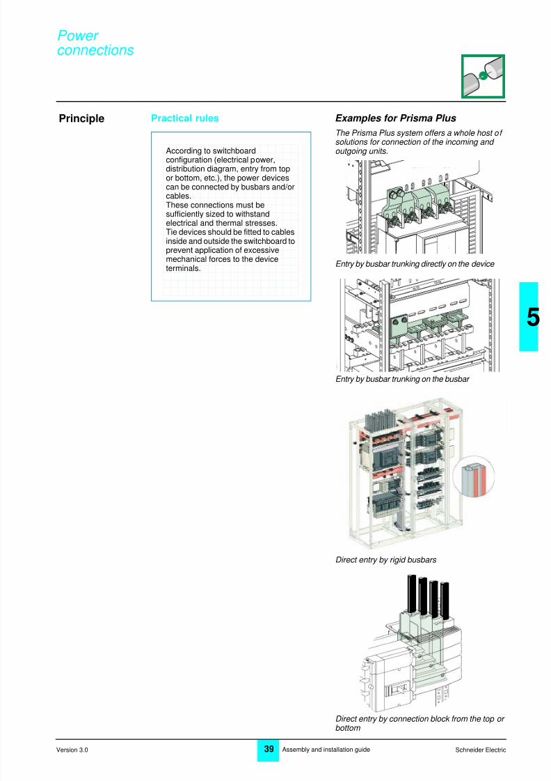
The Prisma Plus system offers a whole host of solutions for connection of the incoming and outgoing units.
Entry by busbar trunking directly on the device
Entry by busbar trunking on the busbar
Direct entry by rigid busbars
Direct entry by connection block from the top or bottom
According to switchboardconfiguration (electrical power,distribution diagram, entry from topor bottom, etc.), the power devicescan be connected by busbars and/orcables.These connections must besufficiently sized to withstandelectrical and thermal stresses.Tie devices should be fitted to cablesinside and outside the switchboard toprevent application of excessivemechanical forces to the deviceterminals.
H
Power connections
8/3/2019 Power Connections
http://slidepdf.com/reader/full/power-connections 4/22
40 Schneider ElectricAssembly and installation guideVersion 3.0
Connecting the power devices
Principle(continued)
Practical rules Examples for Prisma Plus
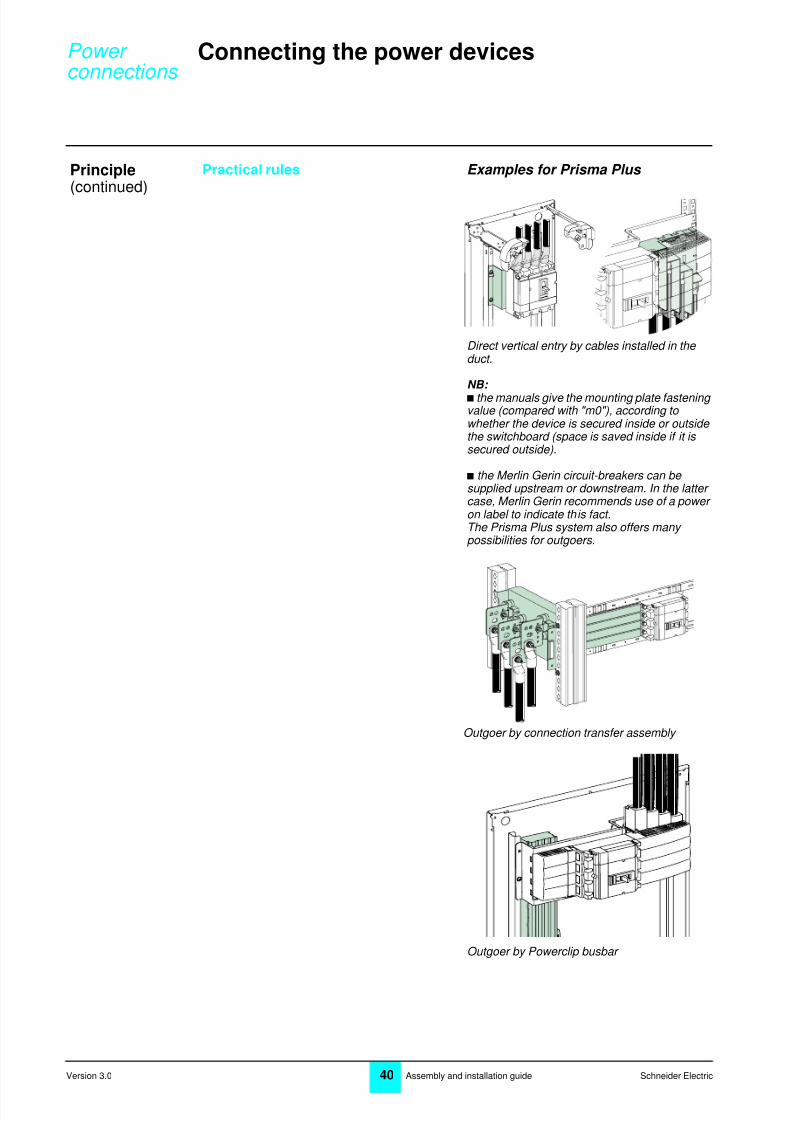
Direct vertical entry by cables installed in the duct.
NB: b the manuals give the mounting plate fastening value (compared with "m0"), according to whether the device is secured inside or outside the switchboard (space is saved inside if it is secured outside).
b the Merlin Gerin circuit-breakers can be supplied upstream or downstream. In the latter case, Merlin Gerin recommends use of a power on label to indicate this fact.The Prisma Plus system also offers many possibilities for outgoers.
Outgoer by connection transfer assembly
Outgoer by Powerclip busbar
Power connections

8/3/2019 Power Connections
http://slidepdf.com/reader/full/power-connections 5/22
Schneider Electric41 Assembly and installation guide
5
Version 3.0
Connecting to the main busbar
Transfer barson the side
Practical rules Examples for Prisma Plus
The transfer busbars must be secured to one another and fixed to the framework. Provide supports as close as possible to the device terminals. If necessary, follow the instructions given in the device technical documentation (Masterpact, etc.).The connection terminals are installed in the duct, to the left or right of the device.
Merlin Gerin recommends a derating coefficient with respect to the main busbars: b 0.85 for edgewise bars b
0.75 for flat bars.Example: For a main1000 A busbar installed in an IP30 switchboard, a copper bar with a cross- section of 400 mm 2 should be used.
The cross-sections for the transfer bars should be: b edgewise bar: 400 mm 2 /0.85 = 470 mm 2 of copper, i.e. one 50 x 10 bar b flat bar: 400 mm 2 /0.75 = 533 mm 2 of copper,i.e. one 60 x 10 bar. The distance between the supports is exactly the same as the one calculated for the main busbar.Locate a support as close as possible to the
device terminals.
Use of transfer bars on the sidesimplifies front connection.
menu
.4.5
.6
.7.8 .9
.95
.98
1
delay
shortt ime
I i
tsd(s)
on I2t
.2
.3.4.4
.1
.2.3
.10off
in s tantan eou
s
longtime
ala rm
Ir
x In
setting
x Ir
22.5
34 5
68
10
Isd
1.5
.512
48 12
16
20
tr(s)
@ 6 Ir24
800
ear th lea
ka ge
123
5 710
20
30
Ðt(ms)
60
.5
140
230350
IÐn(A)
xIn
test
2
4
10
3
68
12
15
off
Transfer conections often have across-section greater than that ofthe main busbar to allow for:b temperature rises at the points ofconnection to the device (proximityeffect)b derating caused, in certain cases,by the orientation of the bars(edgewise or flat bars: see page 12).
Power connections

8/3/2019 Power Connections
http://slidepdf.com/reader/full/power-connections 6/22
42 Schneider ElectricAssembly and installation guideVersion 3.0
Connecting to the main busbar
Directconnection bybars
Practical rules Examples for Prisma Plus
Connection bars can be secured, if possible,using free supports or, failing this, with insulating threaded rods.
A busbar drawing can be supplied when the prefabricated connections are not available in the catalogue.On these drawings, the connections are shown with oblong holes (which help positioning) but to simplify you can make cylindrical holes.
Connection totransferbusbars
Copper connections of the same phase are separated by 5 mm spacers.Flat bars are secured using insulating bars.The space required for connection to the busbar is allowed for in the device height requirements specified in the catalogue.
Linergy busbars: a continuous channel makes it possible to connect bars at any height, without
holes drilled on the busbar.
In this case, use the deratingcoefficient (flat bars).
Power connections
8/3/2019 Power Connections
http://slidepdf.com/reader/full/power-connections 7/22
Schneider Electric43 Assembly and installation guide
5
Version 3.0
Preparing the bars
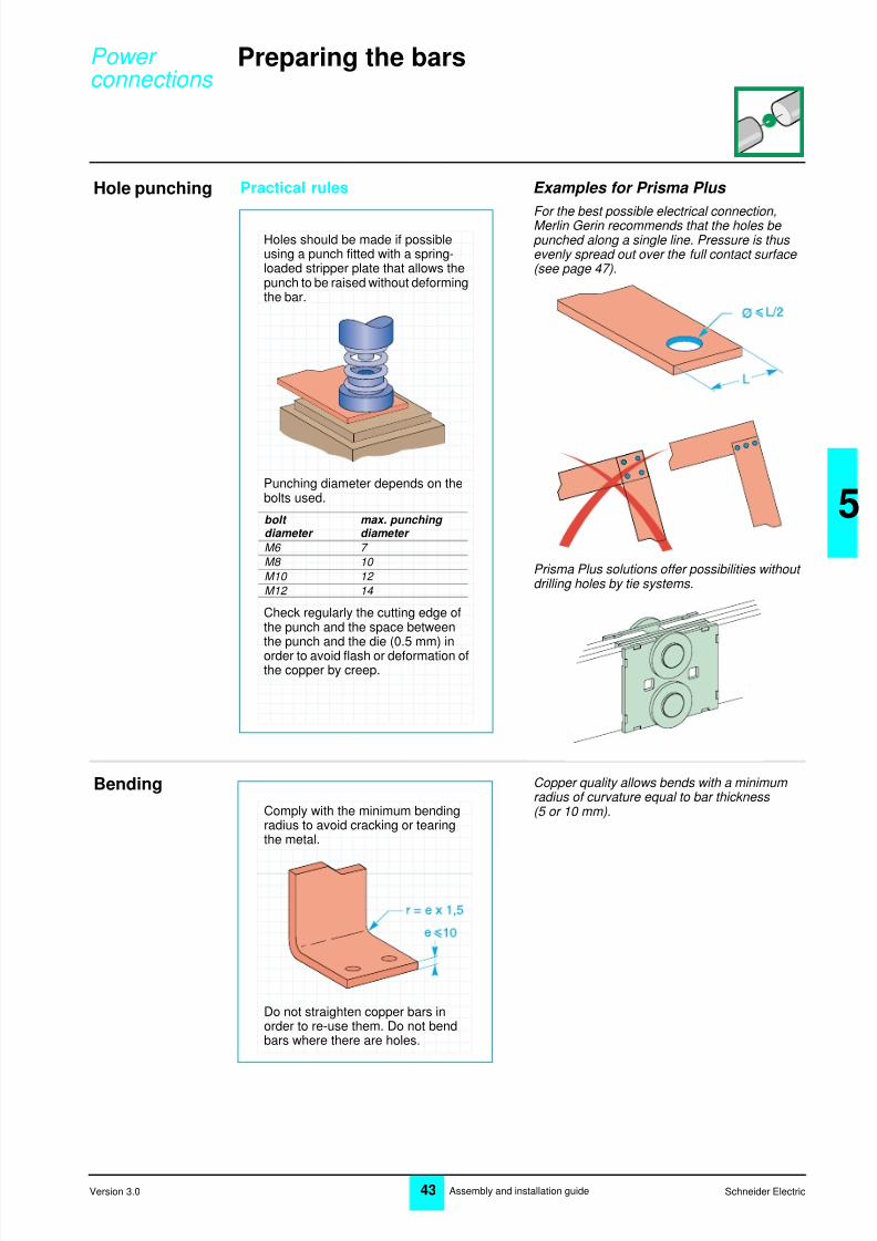
Hole punching Practical rules Examples for Prisma Plus
For the best possible electrical connection,Merlin Gerin recommends that the holes be punched along a single line. Pressure is thus evenly spread out over the full contact surface (see page 47).
Prisma Plus solutions offer possibilities without drilling holes by tie systems.
Bending Copper quality allows bends with a minimum radius of curvature equal to bar thickness (5 or 10 mm).
Holes should be made if possibleusing a punch fitted with a spring-loaded stripper plate that allows thepunch to be raised without deformingthe bar.
Punching diameter depends on thebolts used.
Check regularly the cutting edge ofthe punch and the space betweenthe punch and the die (0.5 mm) in
order to avoid flash or deformation ofthe copper by creep.
bolt max. punching diameter diameter
M6 7 M8 10 M10 12 M12 14
Comply with the minimum bendingradius to avoid cracking or tearingthe metal.
Do not straighten copper bars inorder to re-use them. Do not bendbars where there are holes.
Power connections

8/3/2019 Power Connections
http://slidepdf.com/reader/full/power-connections 8/22
44 Schneider ElectricAssembly and installation guideVersion 3.0
Preparing the bars
Preparingcontactsurfaces
Practical rules Examples for Prisma Plus
With Linergy channelled busbars, you no longer need to sand contact surfaces.A rough, hard surface enhances the quality of the electrical connection by multiplying the contact points.
Surfaces in contact must be clean,dry, flat and exhibit no deepscratches.
Carefully remove any flash on cutsand punch holes and then eliminatethe resulting filings. If necessary,remove any grease from the bar andthen sand contact surfaces lightlywith a fine abrasive cloth.
Power connections
8/3/2019 Power Connections
http://slidepdf.com/reader/full/power-connections 9/22
Schneider Electric45 Assembly and installation guide
5
Version 3.0
Assembling the bars
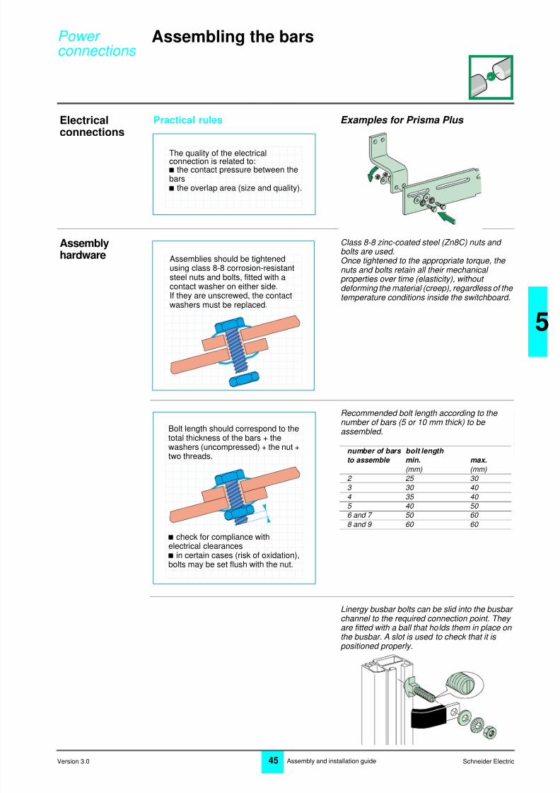
Electricalconnections
Practical rules Examples for Prisma Plus
Assemblyhardware
Class 8-8 zinc-coated steel (Zn8C) nuts and bolts are used.Once tightened to the appropriate torque, the nuts and bolts retain all their mechanical
properties over time (elasticity), without deforming the material (creep), regardless of the temperature conditions inside the switchboard.
Recommended bolt length according to the number of bars (5 or 10 mm thick) to be assembled.
Linergy busbar bolts can be slid into the busbar channel to the required connection point. They are fitted with a ball that holds them in place on the busbar. A slot is used to check that it is positioned properly.
The quality of the electricalconnection is related to:b the contact pressure between thebarsb the overlap area (size and quality).
Assemblies should be tightenedusing class 8-8 corrosion-resistant
steel nuts and bolts, fitted with acontact washer on either side.If they are unscrewed, the contactwashers must be replaced.
Bolt length should correspond to thetotal thickness of the bars + thewashers (uncompressed) + the nut +two threads.
b check for compliance withelectrical clearances
b in certain cases (risk of oxidation),bolts may be set flush with the nut.
number of bars bolt length
to assemble min. max.
(mm) (mm)2 25 30 3 30 40 4 35 40 5 40 50 6 and 7 50 60 8 and 9 60 60
Power connections
8/3/2019 Power Connections
http://slidepdf.com/reader/full/power-connections 10/22
46 Schneider ElectricAssembly and installation guideVersion 3.0
Assembling the bars
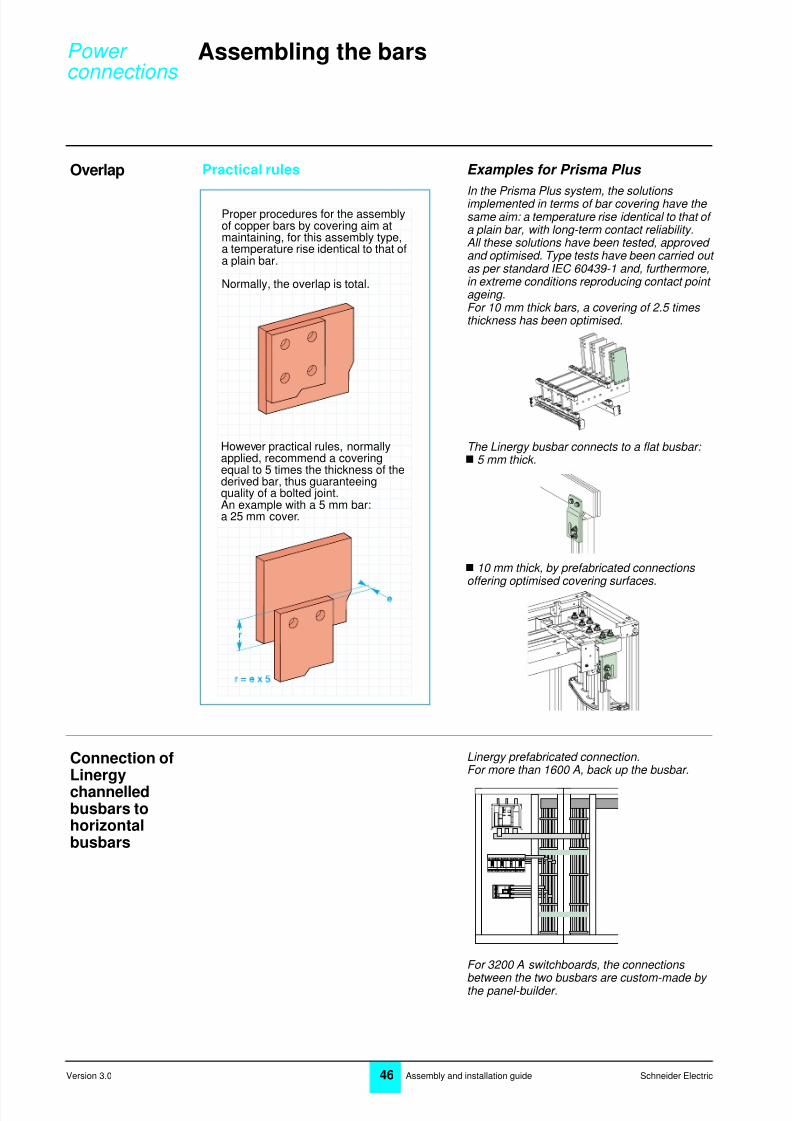
Overlap Practical rules Examples for Prisma Plus
In the Prisma Plus system, the solutions implemented in terms of bar covering have the same aim: a temperature rise identical to that of a plain bar, with long-term contact reliability.All these solutions have been tested, approved and optimised. Type tests have been carried out as per standard IEC 60439-1 and, furthermore,in extreme conditions reproducing contact point ageing.For 10 mm thick bars, a covering of 2.5 times thickness has been optimised.
The Linergy busbar connects to a flat busbar: 5 mm thick.
10 mm thick, by prefabricated connections offering optimised covering surfaces.
Connection ofLinergychannelledbusbars tohorizontalbusbars
Linergy prefabricated connection.For more than 1600 A, back up the busbar.
For 3200 A switchboards, the connections
between the two busbars are custom-made by the panel-builder.
Proper procedures for the assemblyof copper bars by covering aim atmaintaining, for this assembly type,a temperature rise identical to that ofa plain bar.
Normally, the overlap is total.
However practical rules, normallyapplied, recommend a coveringequal to 5 times the thickness of thederived bar, thus guaranteeingquality of a bolted joint.An example with a 5 mm bar:a 25 mm cover.
Power connections
8/3/2019 Power Connections
http://slidepdf.com/reader/full/power-connections 11/22
Schneider Electric47 Assembly and installation guide
5
Version 3.0
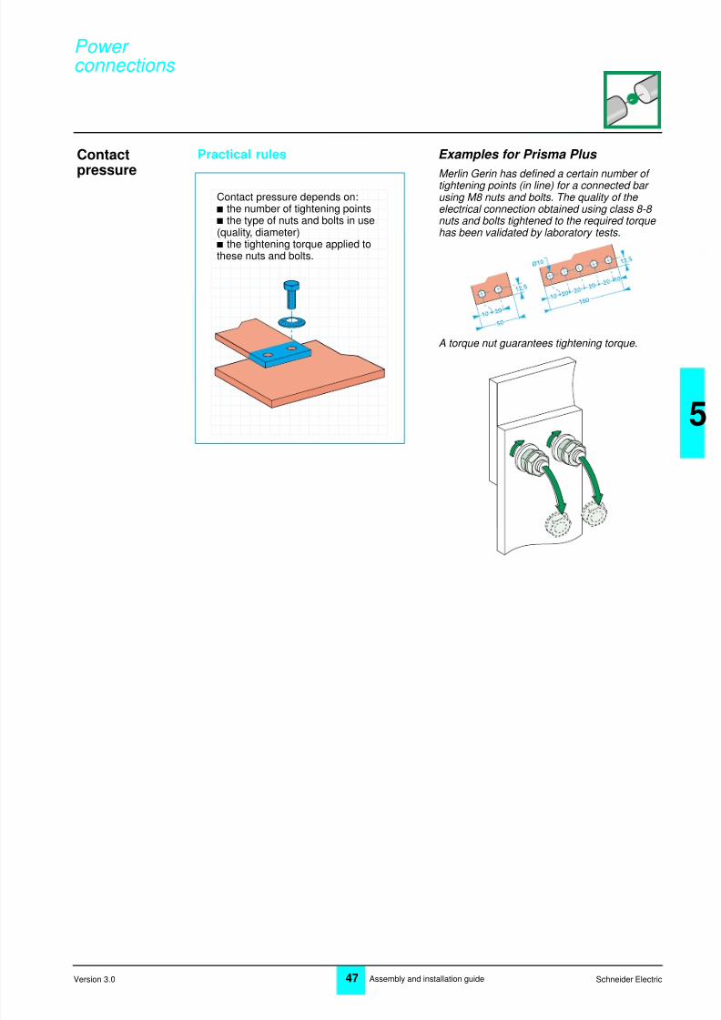
Contactpressure
Practical rules Examples for Prisma Plus
Merlin Gerin has defined a certain number of tightening points (in line) for a connected bar using M8 nuts and bolts. The quality of the electrical connection obtained using class 8-8 nuts and bolts tightened to the required torque has been validated by laboratory tests.
A torque nut guarantees tightening torque.
Contact pressure depends on:b the number of tightening pointsb the type of nuts and bolts in use(quality, diameter)b the tightening torque applied tothese nuts and bolts.
Power connections
8/3/2019 Power Connections
http://slidepdf.com/reader/full/power-connections 12/22
48 Schneider ElectricAssembly and installation guideVersion 3.0
Assembling the bars
Tightening
torque
Practical rules Examples for Prisma Plus
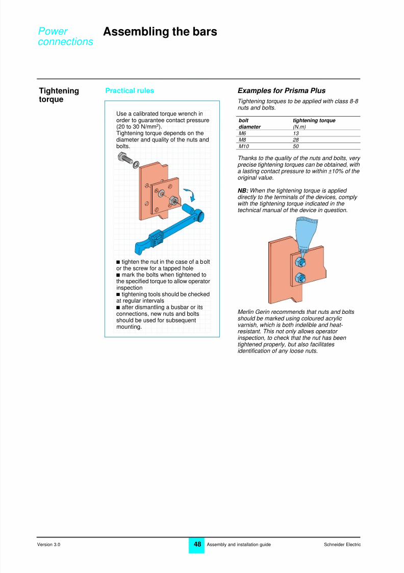
Tightening torques to be applied with class 8-8 nuts and bolts.
Thanks to the quality of the nuts and bolts, very precise tightening torques can be obtained, with a lasting contact pressure to within ±10% of the original value.
NB: When the tightening torque is applied directly to the terminals of the devices, comply with the tightening torque indicated in the technical manual of the device in question.
Merlin Gerin recommends that nuts and bolts should be marked using coloured acrylic varnish, which is both indelible and heat- resistant. This not only allows operator inspection, to check that the nut has been tightened properly, but also facilitates identification of any loose nuts.
Use a calibrated torque wrench inorder to guarantee contact pressure(20 to 30 N/mm2).Tightening torque depends on thediameter and quality of the nuts andbolts.
b tighten the nut in the case of a boltor the screw for a tapped holeb mark the bolts when tightened tothe specified torque to allow operatorinspectionb tightening tools should be checked
at regular intervalsb after dismantling a busbar or itsconnections, new nuts and boltsshould be used for subsequentmounting.
bolt tightening torque
diameter (N.m)
M6 13
M8 28
M10 50
Power connections

8/3/2019 Power Connections
http://slidepdf.com/reader/full/power-connections 13/22
Schneider Electric49 Assembly and installation guide
5
Version 3.0
Connecting with flexible bars
Flexible bartypes
Practical rules Examples for Prisma Plus
To determine the required cross-sections for flexible bars connecting a Merlin Gerin device inside a Prisma Plus enclosure, use the tables below.
Circuit-breakers, switches and fuses: b in a Prisma Plus cubicle b temperature inside switchboard: 60 °C.
(1) the values indicated for circuit-breakers also apply to contactors with the same ratings.
Disconnectors, terminal blocks and busbar/ busbar connections: b in a Prisma Plus cubicle b temperature inside switchboard: 60 °C.
Insulation of the Prisma Plus flexible bars withstands temperature of 125 °C.NB: in all cases, comply with the bar cross- sections given in the manuals.
Cutting tolength
Bending
Standard: IEC 60332
Standard: IEC 60439
Flexible bars must comply withstandard IEC 60332-1 whichguarantees:the electrical characteristics of theconducting coreresistance to temperature and fire ofthe insulation.
To determine the cross-sections offlexible bars required forswitchboards complying withstandard IEC 60439-1, the followingparameters must be considered:location of the device within theenclosuresizes of the other circuitsambient temperature around theswitchboardheat dissipated by the installeddevicetemperature rise generated by theinstalled deviceconnection length
It is therefore necessary to respectthe instructions provided by theelectrical equipment manufacturer.
device s device s
(mm) (mm)IN125 20 x 2 NS250 (1) 20 x 3 IN160 20 x 2 NS400 (1) 32 x 5 IN250 20 x 3 NS630 32 x 8 IN400 32 x 5 Fu250 24 x 5 IN630 32 x 8 Fu400 32 x 5
NS100 (1)
20 x 2 Fu630 32 x 8 NS160 (1) 20 x 2
I max s
(60 °C) (mm)200 A 20 x 2 250 A 20 x 3 400 A 24 x 5 480 A 24 x 6
520 A 32 x 5 580 A 24 x 8 660 A 32 x 8
Cutting, using shears if possible,should leave a clean cut, withoutflash. The cutting length is equal tothe required final length of the bar +
a safety margin (generally 10 mm)which allows for possible slippagebetween the individual copper layerswhen the bar is bent.
Fig. 1
Fig. 2
Flexible bars should be bent by hand,to avoid damaging the insulation,with a curvature radius equivalent toat least the thickness of the bar(see fig. 1).The copper layers, whose position in
relation to each other may havechanged during bending, are thencut off flush(see fig. 2).
Power connections
8/3/2019 Power Connections
http://slidepdf.com/reader/full/power-connections 14/22
50 Schneider ElectricAssembly and installation guideVersion 3.0
Connecting with flexible bars
Insulationstripping
Practical rules Examples for Prisma Plus
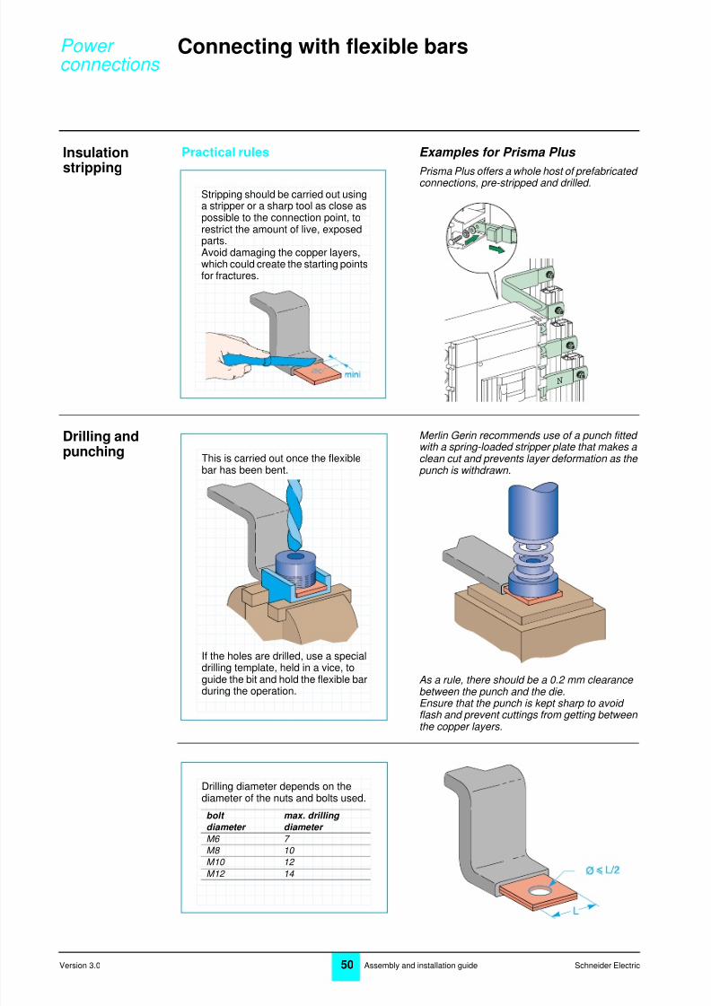
Prisma Plus offers a whole host of prefabricated connections, pre-stripped and drilled.
Drilling andpunching
Merlin Gerin recommends use of a punch fitted with a spring-loaded stripper plate that makes a clean cut and prevents layer deformation as the punch is withdrawn.
As a rule, there should be a 0.2 mm clearance between the punch and the die.
Ensure that the punch is kept sharp to avoid flash and prevent cuttings from getting between the copper layers.
Stripping should be carried out usinga stripper or a sharp tool as close aspossible to the connection point, torestrict the amount of live, exposedparts.Avoid damaging the copper layers,which could create the starting pointsfor fractures.
N
This is carried out once the flexiblebar has been bent.
If the holes are drilled, use a specialdrilling template, held in a vice, toguide the bit and hold the flexible barduring the operation.
Drilling diameter depends on thediameter of the nuts and bolts used.
bolt max. drilling
diameter diameter
M6 7 M8 10 M10 12 M12 14
Power connections

8/3/2019 Power Connections
http://slidepdf.com/reader/full/power-connections 15/22
Schneider Electric51 Assembly and installation guide
5
Version 3.0
Busbars inwall- mount andfloor- standingenclosures andcubicles
Practical rules Examples for Prisma Plus
No sharp edges on busbars in Prisma Plus.
Powerclip busbar in a wall-mount enclosure
Flat busbar at the back of a wall-mount enclosure
Standard: IEC 60439
Standard: IEC 60204
According to standards IEC 60439-1and IEC 60204-1, insulatedconductors must not rest up againstbare live parts or against sharpedges. Their maintenance must becarried out properly.
Power connections
8/3/2019 Power Connections
http://slidepdf.com/reader/full/power-connections 16/22
52 Schneider ElectricAssembly and installation guideVersion 3.0
Connecting with flexible bars
Securing thebars
Practical rules Examples for Prisma Plus
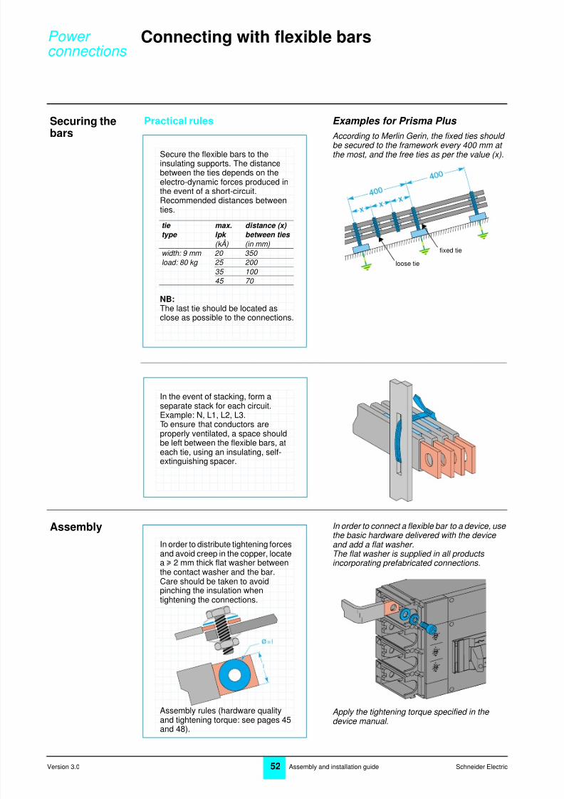
According to Merlin Gerin, the fixed ties should be secured to the framework every 400 mm at the most, and the free ties as per the value (x).
Assembly In order to connect a flexible bar to a device, use the basic hardware delivered with the device and add a flat washer.The flat washer is supplied in all products incorporating prefabricated connections.
Apply the tightening torque specified in the device manual.
Secure the flexible bars to theinsulating supports. The distancebetween the ties depends on theelectro-dynamic forces produced inthe event of a short-circuit.Recommended distances betweenties.
NB:The last tie should be located asclose as possible to the connections.
tie max. distance (x)
type Ipk between ties
(kÂ) (in mm)width: 9 mm 20 350 load: 80 kg 25 200
35 100
45 70
fixed tie
loose tie
In the event of stacking, form aseparate stack for each circuit.Example: N, L1, L2, L3.To ensure that conductors areproperly ventilated, a space shouldbe left between the flexible bars, ateach tie, using an insulating, self-extinguishing spacer.
In order to distribute tightening forcesand avoid creep in the copper, locatea u 2 mm thick flat washer betweenthe contact washer and the bar.Care should be taken to avoidpinching the insulation whentightening the connections.
Assembly rules (hardware qualityand tightening torque: see pages 45and 48).
Power connections

8/3/2019 Power Connections
http://slidepdf.com/reader/full/power-connections 17/22
Schneider Electric53 Assembly and installation guide
5
Version 3.0
Connection tothe busbars
Practical rules Examples for Prisma Plus
For each current, there is a prefabricated connection for the device/busbar connection.
Insulated flexible prefabricated connection
Bare bar prefabricated connection
If the busbars have several bars perphase, the connection points must bedistributed over the various bars ofthe same phase.
Flexible bars should be connectedwithout separating the copper layers.
Power connections

8/3/2019 Power Connections
http://slidepdf.com/reader/full/power-connections 18/22
54 Schneider ElectricAssembly and installation guideVersion 3.0
Connecting with cables
Principle Practical rules Examples for Prisma Plus
Above 125 A, Merlin Gerin recommends use of flexible bars for connection between the main busbar and the outgoers.
Cablecharacteristics
Merlin Gerin recommends use of a U 1000 flexible or semi-rigid cable (1000 V insulation).
For an operating voltage of less than half the cable insulating voltage, or in other words < 500 V, these cables are treated as belonging
to class 2. Consequently, they may be secured directly to metal supports without inserting an insulator.Merlin Gerin recommends black power cables with a blue mark for the neutral and a green/ yellow mark for the protective conductor.
Cable cross-section
Copper cable cross-sections recommended for connecting circuit-breakers on a switchboard with an external temperature of 35 °C.
Cables may be used for all mediumpower connections.However, above a certain powerrating, cable connections becomemore difficult on account ofrequirements such as the cross-section of the cables, the number ofconductors, the radius of curvature orthe space available inside theenclosure.
As a rule, flexible or semi-rigidcopper cables are used for wiring theinside of a switchboard.H05VK cables with 500 V insulationor H07VK cables with 750 Vinsulation can be used.The standard cable has a resistantinsulator at 105 °C.
Cable cross-section should becompatible with:b the current to be carriedb the ambient temperaturesurrounding the conductors.
cross- permissible current (A)
section switchboard switchboard
(mm 2 ) IP y yy y 30 ( ∼∼∼∼ 60°C) IP > 31 ( ∼∼∼∼ 70°C)
separate bundle separate bundle
1.5 16 14 14 12 2.5 25 22 23 20 4 32 28 29 24 6 40 36 39 33 10 63 55 55 50 16 90 80 77 70 25 110 100 100 93 35 135 125 125 120
Power connections

8/3/2019 Power Connections
http://slidepdf.com/reader/full/power-connections 19/22
Schneider Electric55 Assembly and installation guide
5
Version 3.0
Bundles Practical rules Examples for Prisma Plus
Number of cables recommended according to their diameter :
Stripping For u 6 mm 2 cross-sections, lugs offer better tightening, without risk of creep in the terminal.For cross-sections < 6 mm 2 , Merlin Gerin prefers use of direct connection in the device terminal.However, it also proposes a variety of connection types: steel terminals, multi-hole terminals, reduced lugs, etc
Bundles are normally created circuitby circuit.The number of cables by bundledepends on cable diameter.
They must be assembled beforebeing secured to their support.Distance between securing centres:(see page 57).
cable number of cables
cross-section by bundle
(in mm 2 )y 10 8 16 to 35 4
Use a wire stripper taking care toavoid cutting the strands ordamaging the insulation.
The length stripped should allow for:b the depth of the lug to be crimped
b the depth of the connection tunnelon the device.
Power connections
8/3/2019 Power Connections
http://slidepdf.com/reader/full/power-connections 20/22
56 Schneider ElectricAssembly and installation guideVersion 3.0
Connecting with cables
Lug crimping Practical rules Examples for Prisma Plus
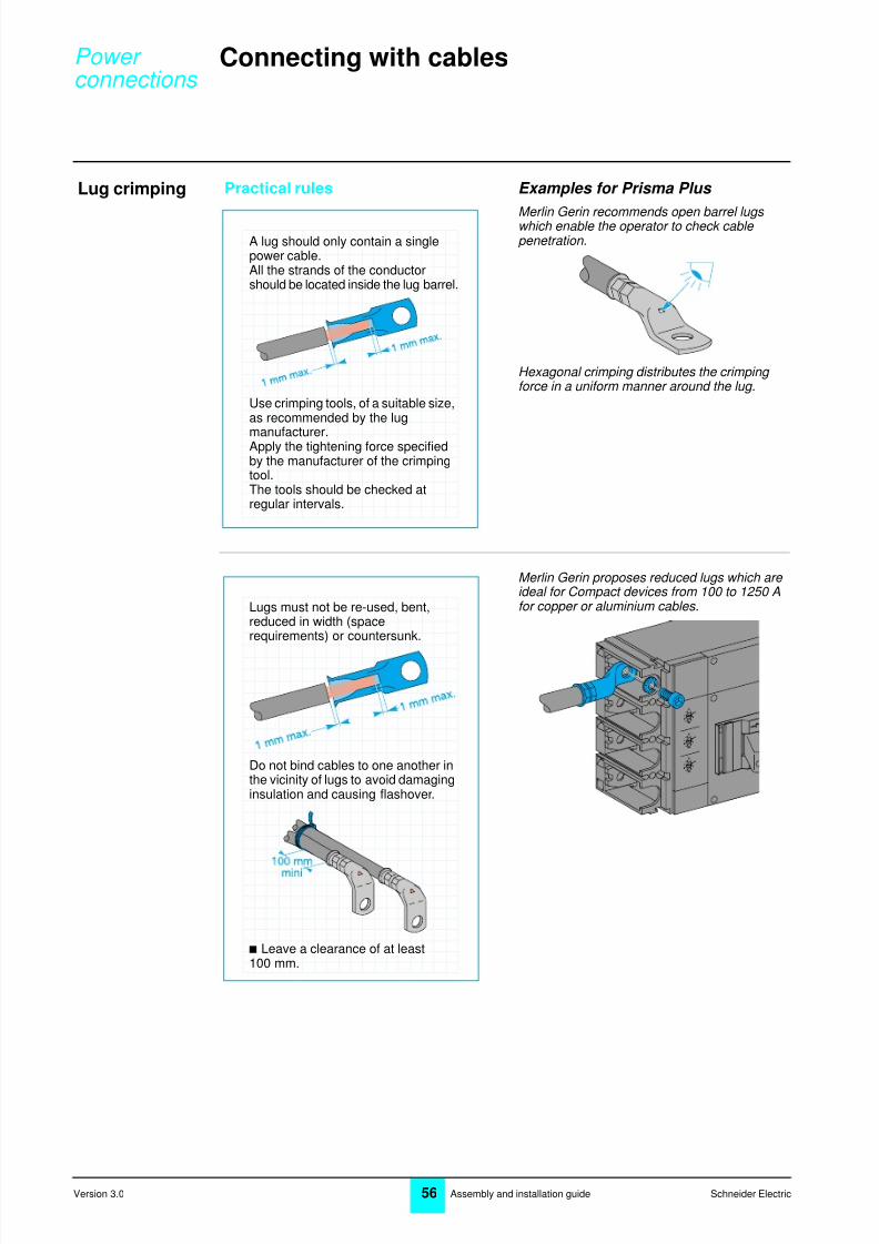
Merlin Gerin recommends open barrel lugs which enable the operator to check cable penetration.
Hexagonal crimping distributes the crimping force in a uniform manner around the lug.
Merlin Gerin proposes reduced lugs which are ideal for Compact devices from 100 to 1250 Afor copper or aluminium cables.
A lug should only contain a singlepower cable.All the strands of the conductorshould be located inside the lug barrel.
Use crimping tools, of a suitable size,as recommended by the lug
manufacturer.Apply the tightening force specifiedby the manufacturer of the crimpingtool.The tools should be checked atregular intervals.
Lugs must not be re-used, bent,reduced in width (spacerequirements) or countersunk.
Do not bind cables to one another inthe vicinity of lugs to avoid damaginginsulation and causing flashover.
b Leave a clearance of at least100 mm.
Power connections
8/3/2019 Power Connections
http://slidepdf.com/reader/full/power-connections 21/22
Schneider Electric57 Assembly and installation guide
5
Version 3.0
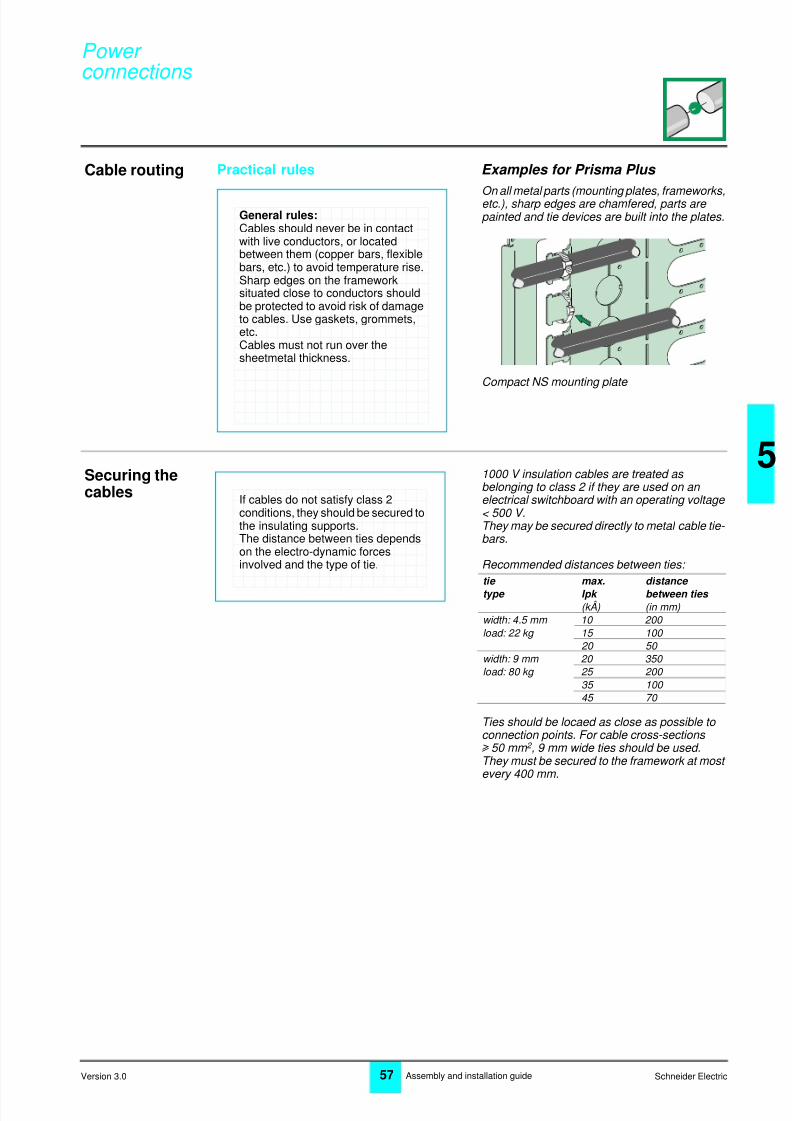
Cable routing Practical rules Examples for Prisma Plus
On all metal parts (mounting plates, frameworks,etc.), sharp edges are chamfered, parts are painted and tie devices are built into the plates.
Compact NS mounting plate
Securing thecables
1000 V insulation cables are treated as belonging to class 2 if they are used on an electrical switchboard with an operating voltage < 500 V.They may be secured directly to metal cable tie- bars.
Recommended distances between ties:
Ties should be locaed as close as possible to connection points. For cable cross-sections u 50 mm 2 , 9 mm wide ties should be used.They must be secured to the framework at most every 400 mm.
General rules:Cables should never be in contactwith live conductors, or locatedbetween them (copper bars, flexiblebars, etc.) to avoid temperature rise.Sharp edges on the frameworksituated close to conductors shouldbe protected to avoid risk of damageto cables. Use gaskets, grommets,etc.Cables must not run over thesheetmetal thickness.
If cables do not satisfy class 2conditions, they should be secured tothe insulating supports.The distance between ties dependson the electro-dynamic forcesinvolved and the type of tie.
tie max. distance
type Ipk between ties
(kÂ) (in mm)width: 4.5 mm 10 200 load: 22 kg 15 100
20 50 width: 9 mm 20 350 load: 80 kg 25 200
35 100 45 70
Power connections

8/3/2019 Power Connections
http://slidepdf.com/reader/full/power-connections 22/22
Distribution blocks
Distributionblocks
Practical rules Examples for Prisma Plus
Spring terminal With connection accessories such as Multiclip,Polybloc, Distribloc, a spring terminal rather than a screw is used to tighten the cables.These accessories are all fully comptible with the breaking capacity of the Merlin Gerin devices.Contact pressure of the spring is automatically adapted to conductor cross-section and does not depend on the operator.Tightening is very reliable as it is not sensitive to vibrations or temperature variations, and is guaranteed over time.
Do not fit ferrules on spring terminals. Each terminal can only take a single wire.Use a flat screwdriver with cylindrical cross-
section only to open the spring.Tests have been carried out on terminals both alone and in association with Merlin Gerin devices. They are shown to comply with standards IEC 60947-7 (cable withstand tests)and IEC 60439-1 (temperature rise and electro- dynamic tests).
Tunnel terminal This connection type such as on additional block or Multiclip allows several cables to be connected. However it is best not to use a ferrule.Tunnel terminals are used mainly for supplying the various distribution blocks and certain circuit-breakers (Multi 9).
Tunnel terminals on Multiclip distribution block
Standard: IEC 60947
Standard: IEC 60439
Distribution blocks must withstandthermal stresses generated in theevent of a short-circuit.
Tighten taking care not to cut theconductor strands. In the case ofterminals with pointed screws, it isadvisable to fit ferrules on the ends ofmulti-strand conductors.The ferrules must be adapted tocable cross-sections and terminaldimensions and crimped usingsuitable tools for the purpose.For spring terminals, comply with thestripping lengths and tighteningtorques of the various connectiontypes.
1 3
2
12
N
L1
L2
Power connections