power conversion for a novel ac/dc aircraft electrical ...eprints.nottingham.ac.uk/34478/1/power...
TRANSCRIPT

Power Conversion for a Novel AC/DC Aircraft
Electrical Distribution System
Andrew Trentin, Pericle Zanchetta, Pat Wheeler, Jon Clare
Abstract: This paper proposes a novel and compact AC/DC electrical distribution system for new generation
aircraft. In these new aircraft power systems, all loads are fed by two dc bus systems: at 28V and at +/-270V.
The electrical distribution system, whose design and implementation are described in this paper, has only one
primary AC source (360-900Hz at 230V) with all the required dc voltage levels being derived from this source.
This solution enables elimination of the complex mechanical coupling apparatus currently used, for fixed
frequency AC systems, to maintain the generator speed at constant level while the engines operate at variable
speed. Under the proposed solution, all conversion stages needed to generate the various output voltage levels
are implemented using power converters assembled in one unit. Each converter has a current control loop in
order to regulate the output current even during output line short circuits and also to limit the inrush current
to the circuit at turn-on. To prove the concept a 5 kW prototype was designed and tested, and demonstrated to
meet all the specifications within relevant standards regarding input and output power quality.
Index Terms: 3-phase buck-type PWM rectifier, DC/DC converter, Multiple DC Network
1. Introduction
Modern aircraft employ an increasing amount of electrical power in place of hydraulic, pneumatic and mechanical
power. This has led to the massively increased use of power converters and electrical drives for different on board
applications. In fact within the so called More Electric Aircraft (MEA) approach, electrical power is employed for
primary and secondary systems, including flight surface actuators, de-icing, flight control, passenger entertainment,
cabin air conditioning and engine start. The engine control has also significantly changed, removing the necessity for
many hydraulic systems and the bleed air system; thus the MEA will be a lighter and more efficient airplane, resulting
in energy and fuel saving, higher reliability and reduced running costs [1]-[4]. To meet the requirements, it is becoming
vital to produce lighter, more efficient and more reliable power converters to be installed on board.
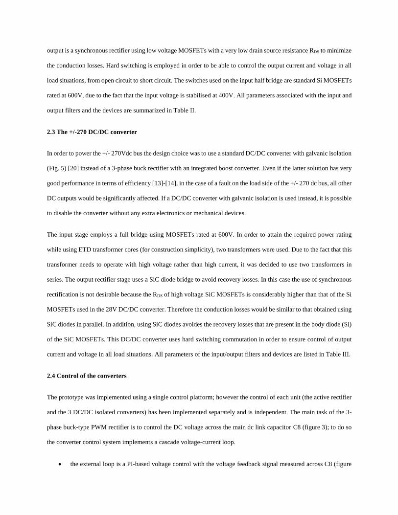
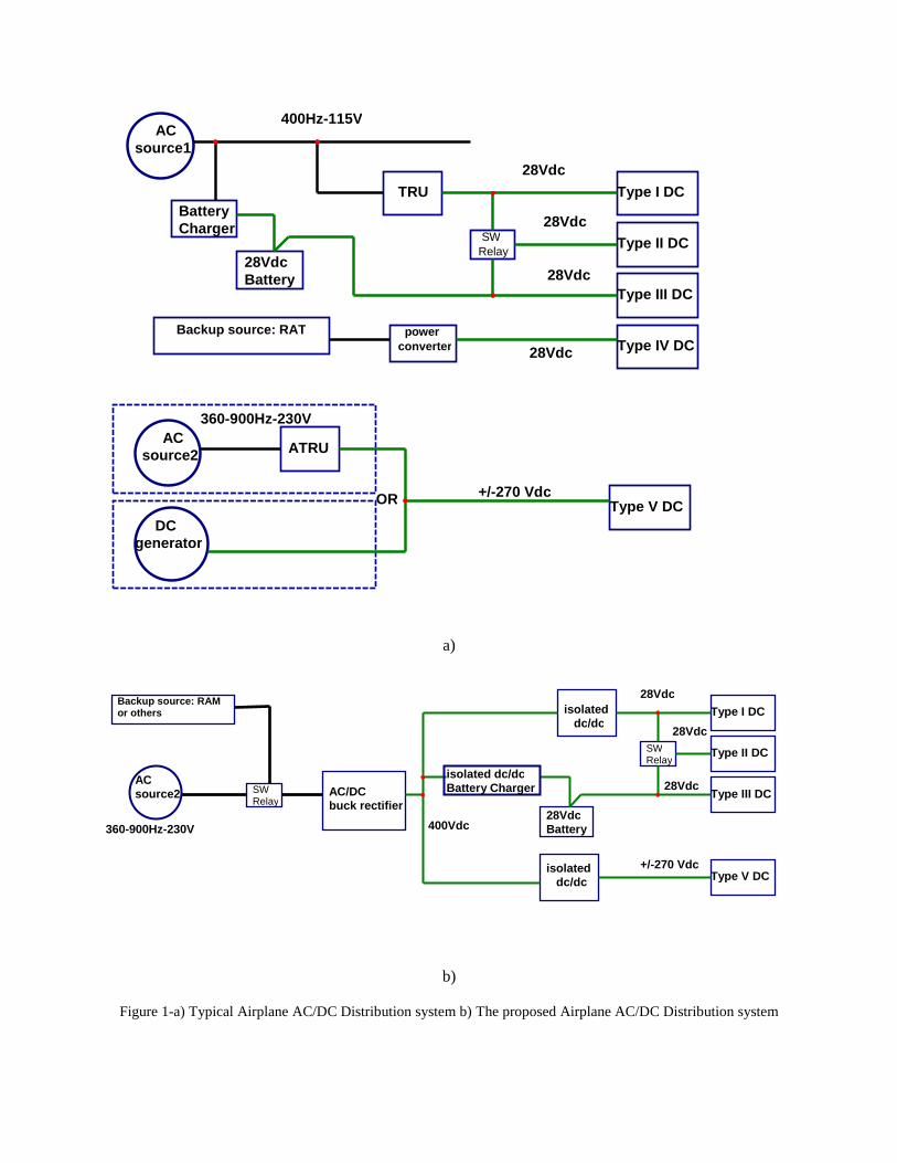
Figure 1a shows the state of the art of a modern aircraft AC/DC distribution system. The primary source to generate
the 28Vdc power line is the 3 phase AC source1 (115V at fixed frequency 400Hz). A Transformer Rectifier Unit
(TRU) generates the 28Vdc. During extreme emergency situations the power source becomes the ram air turbine
(RAT) generator. Figure 1 also shows the presence of a backup battery system and its associated battery charger fed
by the same AC source 1. The high voltage DC power line (HVDC), with a nominal voltage of +/270V can be supplied
by two different power sources according to design choices: either a high voltage DC generator or an Auto transformer
Rectifier Unit (ATRU) powered by AC source 2. This high voltage AC source (HVAC) is 230Vphase to neutral in

Variable Speed Variable Frequency (VSVF) systems, with a frequency variation between 360-900Hz.
This paper proposes a novel AC/DC aircraft distribution system, whose structure is shown in figure 1-b. The main
differences of the proposed scheme, compared to the traditional one are:
The main input source is the VSVF (variable speed, variable frequency) AC generator at high voltage
(HVAC); there is no need for a 400Hz-115Vac generator.
The TRU and ATRU (that normally work in a low frequency range <1KHZ with bulky magnetics) are
eliminated. Their functions are replaced by isolated DC/DC converter(s) with high frequency transformers
(usually within the range 20kHz-100kHz)
All isolated DC/DC converters in the scheme are fed by the output voltage of the AC/DC buck rectifier, at a rated
value of 400V [5]-[6]-[7]. Each DC/DC converter includes current control, in order to regulate and limit the output
current in all operating conditions (including implementing output I2t protection).
In this study a prototype of the proposed distribution system has been designed, assembled and tested with all
components shown in figure 1-b, with the exception of the battery storage system. The power level is around 5kW
and the system features three different DC outputs: two at 28V and 20A (called V1 and V2) and one at +/- 270V at 6
A (called V3). The prototype is shown in figure 2, where it is possible to identify the different elements:
1) The 3-phase PWM buck-type rectifier
2) The main dc link capacitor (at 400V)
3) The first DC/DC converter from 400V to 28V, 15A (V1)
4) The second DC/DC converter from 400V to 28V, 15A (V2)
5) The DC/DC converter from 400V to +/- 270V, 5A (V3)
6) The digital control unit for all power electronics systems
All outputs have been designed for an overload capability of 30%.
The remainder of this paper describes the design and implementation of the individual power conversion blocks and
the comprehensive experimental results obtained. Control strategies for the individual converters are described.
Stability analysis of complete DC networks is considered beyond the scope of the paper and has been widely discussed

elsewhere, for example [8].
2. Description of the system
2.1 The 3-phase buck-type PWM rectifier
The circuit of a 3-phase buck-type PWM rectifier [9]-[19] is shown in figure 3. The main characteristics of this
converter can be summarised as follows:
The maximum output voltage is equal to 86.6% of the input phase-to-phase voltage.
It is capable of achieving almost sinusoidal input currents with the use of a small input filter designed to
remove switching harmonic components.
Capability to control the input power factor (under some limitations relative to the maximum output voltage).
It does not need any pre-charge circuit.
In recent years this converter topology has generated substantial attention from industry and the research community
for aircraft applications particularly for its high reliability [9], [17].
Another important advantage of this topology for aircraft applications is its low weight [9]: the main input filter is not
designed to store any bulk energy, but only to filter the switching harmonics, while the output filter can be designed
according to different criteria: filtering the switching harmonics (in which case it can be very small) or it can be used
to store a sufficient amount of energy to maintain the quality of the output voltage during faults and/or interruption of
the input voltage.
In order to meet aerospace power quality standards for the input current and at the same time maintain a reduced size
of the input filter, the switching frequency must be chosen as high as possible [19]. This is made possible by using
SiC MOSFETs instead of traditional IGBTs without compromising the converter efficiency. The parameters of the
input and output filters together with the devices used are listed in Table I.
2.2 The 400-28V DC/DC converter
To generate the 28V dc bus voltage, traditional DC/DC converters with transformer isolation (see figure 4) are used
[20]. The input stage is represented by a half bridge configuration followed by an isolated centre-tap transformer; the
output is a synchronous rectifier using low voltage MOSFETs with a very low drain source resistance RDS to minimize
the conduction losses. Hard switching is employed in order to be able to control the output current and voltage in all
load situations, from open circuit to short circuit. The switches used on the input half bridge are standard Si MOSFETs
rated at 600V, due to the fact that the input voltage is stabilised at 400V. All parameters associated with the input and
output filters and the devices are summarized in Table II.
2.3 The +/-270 DC/DC converter
In order to power the +/- 270Vdc bus the design choice was to use a standard DC/DC converter with galvanic isolation
(Fig. 5) [20] instead of a 3-phase buck rectifier with an integrated boost converter. Even if the latter solution has very
good performance in terms of efficiency [13]-[14], in the case of a fault on the load side of the +/- 270 dc bus, all other
DC outputs would be significantly affected. If a DC/DC converter with galvanic isolation is used instead, it is possible
to disable the converter without any extra electronics or mechanical devices.
The input stage employs a full bridge using MOSFETs rated at 600V. In order to attain the required power rating
while using ETD transformer cores (for construction simplicity), two transformers were used. Due to the fact that this
transformer needs to operate with high voltage rather than high current, it was decided to use two transformers in
series. The output rectifier stage uses a SiC diode bridge to avoid recovery losses. In this case the use of synchronous
rectification is not desirable because the RDS of high voltage SiC MOSFETs is considerably higher than that of the Si
MOSFETs used in the 28V DC/DC converter. Therefore the conduction losses would be similar to that obtained using
SiC diodes in parallel. In addition, using SiC diodes avoides the recovery losses that are present in the body diode (Si)
of the SiC MOSFETs. This DC/DC converter uses hard switching commutation in order to ensure control of output
current and voltage in all load situations. All parameters of the input/output filters and devices are listed in Table III.
2.4 Control of the converters
The prototype was implemented using a single control platform; however the control of each unit (the active rectifier
and the 3 DC/DC isolated converters) has been implemented separately and is independent. The main task of the 3-
phase buck-type PWM rectifier is to control the DC voltage across the main dc link capacitor C8 (figure 3); to do so
the converter control system implements a cascade voltage-current loop.
the external loop is a PI-based voltage control with the voltage feedback signal measured across C8 (figure
8)
The internal current loop is implemented using a second order controller with plant pole-zero cancellation.
The current sensor measures the current flowing through L3 (figure 8)
Full details about the control of the 3-phase buck-type PWM rectifier are reported in [18].
The converter control system for the three DC/DC isolated converters implements a simple cascade voltage –current
loop as shown in figure 6:
the external loop is a PI-based voltage control with output voltage feedback
the internal loop is a PI-based current control (the current sensor for the 28V scheme is a shunt resistor (see
figure 4), while the current sensor for the 540Vdc scheme is located on L6 (see figure 5)
The performance of the control system is shown in detail in figure 7, which depicts experimental results with data
recorded by the control platform with a sampling time of 50us. Figure 7a shows the turn on sequence of each dc/dc
power converter, while part b) shows the behavior of the low voltage converter when the high voltage one is turned
off. It is clear that the 28V rail remains inside the limit line when there are large step loads on the V3 output.
3. Experimental results
3.1 AC input power quality
Figure 8 shows oscilloscope traces of the AC input line current and line voltage at the rated power condition, when
the input frequency is 900 Hz. It clear that the voltage and current are almost in phase: more details regarding power
factor values are reported in Table IV. Figure 8b show the spectrum of the line current and figure 8c presents a zoom
of figure 8b at lower frequencies, highlighting that the designed system fulfils the aircraft standards specification.
3.2 28V DC output power quality
Figure 9 shows oscilloscope traces of the voltage and current at the output of the 28V dc/dc converter, while figure
9b shows the spectrum of the output voltage plotted with the standard limits, highlighting that this part of the designed
system also fulfils the aircraft standards specification.
3.3 The +/-270V DC output power quality

Figure 10 shows the input current and input voltage of the transformer. Figure 11a shows oscilloscope traces of the
positive and negative voltage (+/-270), the differential voltage (540V) and the output current for the +/-270V high
voltage DC/DC power converter. Figure 11b shows the spectrum of the differential output voltage plotted with its
standards limit; figure 11c show the spectrum of the common mode voltage plotted against the standards limit while
figure 11d presents a zoom of Figure 11c on the vertical axis. Both differential and common mode voltage largely
fulfill the aircraft standards specification.
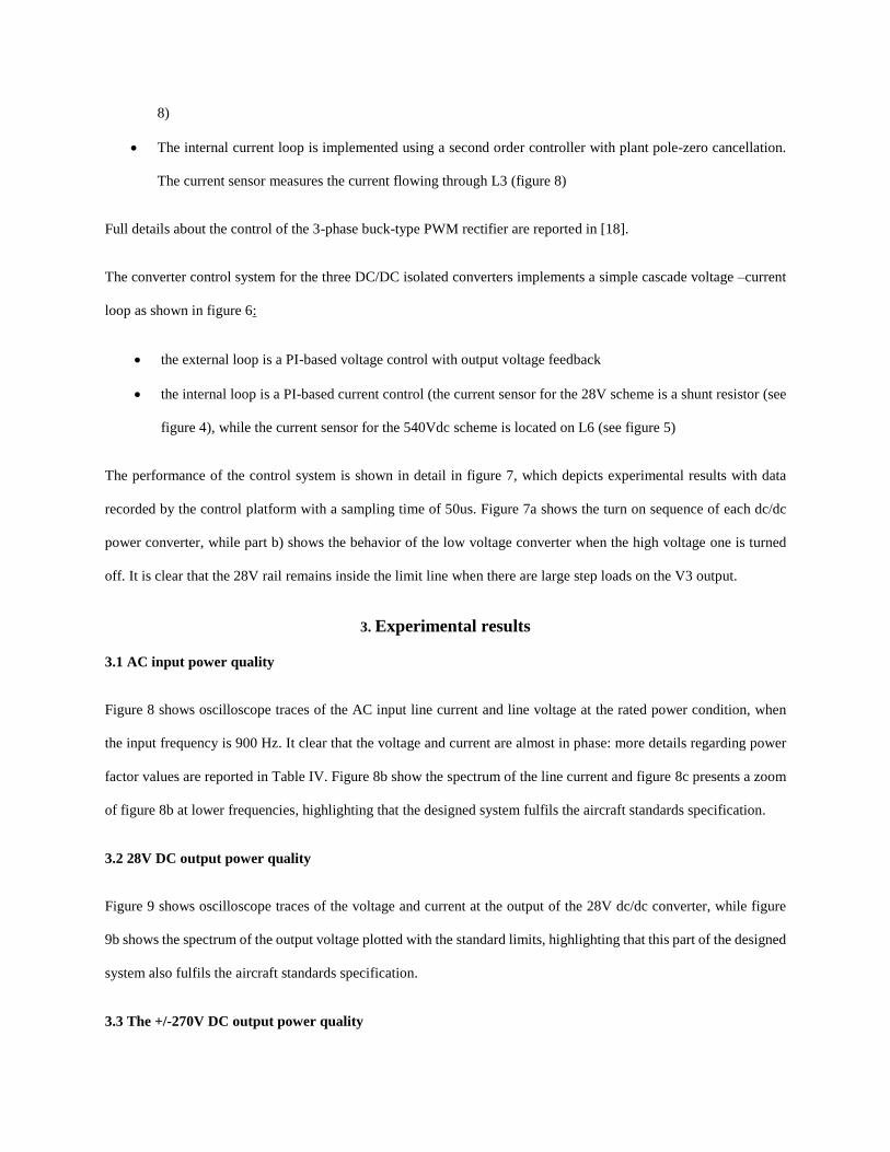
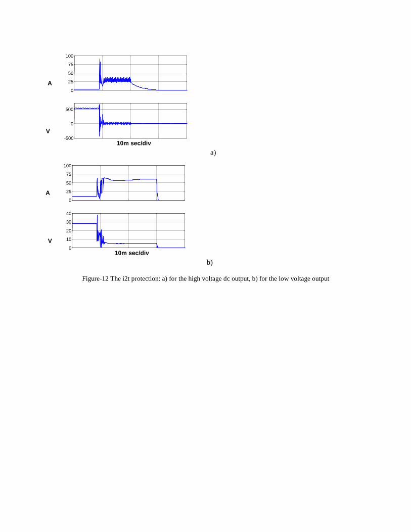
3.4 I2t protection for all DC outputs
All DC/DC converters in the proposed distribution system are equipped with i2t protection at the output. In this
implementation, when a short circuit occurs, each single converter control will limit its output current to a fixed value
(4 times rated for the low voltage converters and 5 times rated for the high voltage converter) until the computation
of I2t reaches its limit, when the converter is disabled. Figure 12a shows the behavior of the high voltage DC/DC
converter during a short circuit, while figure 12b shows the behavior of the low voltage dc/dc converter during a short
circuit. This data was recorded by the control unit with a sampling time of 50s. When the short circuit occurs, the
control system has some difficulty to maintain the current level to a fixed value; this is due to two specific factors,
firstly there is a limitation due to the controller bandwidth and secondly the short circuit was generated using a standard
contactor which has “bounce” and creates some ringing effects.
3.6 Efficiency of the whole distribution system
The efficiency of the proposed AC/DC distribution system was measured using two power analyzers (PPA2530), one
placed at the input and the second one at the output of the system. Table IV summarizes the measured characteristics
of the distribution system under different load conditions and also at different input frequencies. In all tests the power
factor is almost equal to 1 and the total efficiency is between 91-93 %. Table V shows the efficiency for the 3-phase
buck-type rectifier when the dc output voltage reference has been set to 390V. At low power levels, in order to maintain
unity power factor operation, the dc output voltage has been limited so as to compensate the high reactive power of
the input capacitor due to the high input frequency [19]. The efficiency of the 3-phase buck-type rectifier including
input and output filters is around 96.2%; this means that the high voltage DC/DC converter has an estimated efficiency
of around 96.7%, and the low voltage DC/DC converter has an efficiency of around 94%.

4. Discussion
The experimental investigation carried out in this paper has demonstrated that it is possible to use an integrated power
electronics based solution for an AC/DC distribution system in aircraft applications. At the input (AC) the proposed
conversion unit exhibits unity power factor operation for almost all operating conditions, well within the standard
limits. The input current has a very high quality with its entire harmonic spectrum up to 150kHz (EMC frequencies
were not considered in this study) within aircraft standards specifications; this result was achieved due to the use of
high voltage SiC MOSFETs presenting very low switching losses. In addition all DC outputs feature a power quality
within the aircraft standards specifications. The DC/DC converters are also easy to control and it is possible to regulate
the output current during short circuits with the implemented i2t protection. Thanks to the configuration of the DC/DC
converters with an isolation transformer, the common mode voltage does not contain any harmonics of the supply
frequency; however this is not the only advantage given by the galvanic isolation. The more significant advantage is
that if a fault occurs on the load side of each single converter, it is possible to disable that particular converter without
any extra electronics or mechanical devices, while the DC bus at 400V will still be available to feed the other DC
outputs.
Another significant advantage of the proposed distribution system, over a fixed frequency AC generation system, is
that it enables the elimination of complex mechanical coupling apparatus currently used to maintain the generator
speed at a constant level, while the engines are operated at variable speed. In this way the presence of the TRU and
ATRU (that normally work at low frequency <1k Hz) is avoided.
The total efficiency of 91-93% measured during the experimental tests is not particularly high. However there is
considerable scop to improve this, since it is possible to increase the efficiency of the power electronic systems by
increasing the number of MOSFETs and SiC diodes in parallel to reduce conduction losses [5]. It is also possible to
reduce the losses of the passive elements, such as inductors and transformers, through an optimisation including
efficiency size and weight, all of which are important targets in aircraft applications.
5. Conclusions
This paper has presented a novel compact AC/DC electrical distribution system for new generation aircraft featuring
two dc buses at 28V and at +/-270V. The proposed distribution system only has one primary AC source (360-900Hz
at 230V), while all the required dc voltage levels are derived from this primary source. All conversion stages needed

to generate the various output voltage levels are implemented using power converters assembled in one unit.
Experimental results obtained from a 5 kW prototype, demonstrates that all the aircraft standard specifications
regarding input and output power quality are met.
6. References
[1] Mecrow, B., Cullen, J., and Mellor, P.: “Editorial - Electrical machines and drives for the more electric aircraft”,
Electric Power Applications, IET, Volume: 5 , Issue: 1 , Publication Year: 2011 , Page(s): 1 – 2
[2] Trentin, A., Zanchetta, P., Wheeler, P., and Clare, J.: “Power flow analysis in electro-mechanical actuators for
civil aircraft”, Electric Power Applications, IET, Volume: 5 , Issue: 1 , Publication Year: 2011 , Page(s): 48 – 58
[3] Cross, A., Baghramian, A., and Forsyth, A.: “Approximate, average, dynamic models of uncontrolled rectifiers
for aircraft applications”, Power Electronics, IET, Volume: 2 , Issue: 4 , Publication Year: 2009 , Page(s): 398 – 409
[4] Jomier T., “Final-Public MOET Technical Report”, Dec 2009, website: www.eurtd.com/moet
[5] Stupar , A.; Friedli , T.; Minibock, J., and Kolar, J. W.: “Towards a 99% Efficient Three-Phase Buck-Type PFC
Rectifier for 400-V DC Distribution Systems”, Power Electronics, IEEE Transactions on, Volume: 27 , Issue: 4,
Publication Year: 2012 , Page(s): 1732 – 1744
[6] A. Pratt, P. Kumar, and T. V. Aldridge, “Evaluation of 400 V DC distribution in Telco and data centers to improve
energy efficiency,” in Proc. 29th Int. Telecommun. Energy Conf., Rome, Italy, Oct. 2007,pp-32-39
[7] A. Matsumoto, A. Fukui, T. Takeda, K. Hirose, and M. Yamasaki, “Development of 400 Vdc power distribution
system and 400 Vdc output rectifier ,” in Proc. 31st Int. Telecommun. Energy Conf., Incheon, Korea, Oct. 2009, pp-
1-5
[8] Barruel, F., Retiere, N., Schanen, J.L., Caisley, A., “Stability Approach for Vehicles DC Power Network:
Application to Aircraft On-board System”, Power Electronics Specialists Conference, 2005. PESC '05. IEEE 36th,
Publication Year: 2005, Page(s): 1163 - 1169
[9] Guanghai Gong, Heldwein, M.L., Drofenik, U., Minibock, J., Mino, K., and Kolar, J.W.: “Comparative evaluation

of three-phase high-power-factor AC-DC converter concepts for application in future More Electric Aircraft”,
Industrial Electronics, IEEE Transactions on, Volume: 52 , Issue: 3 , Publication Year: 2005 , Page(s): 727 – 737
[10] Malesani, L., and Tenti, P.: “Three-Phase AC/DC PWM Converter with Sinusoidal AC Currents and Minimum
Filter Requirements”, Industry Applications, IEEE Transactions on, Volume: IA-23 , Issue: 1, Publication Year: 1987
, Page(s): 71 - 77
[11] Nussbaumer, T., Baumann, M., and Kolar, J.W: “Comprehensive Design of a Three-Phase Three-Switch Buck-
Type PWM Rectifier”, Power Electronics, IEEE Transactions on, Volume: 22 , Issue: 2 , Publication Year: 2007 ,
Page(s): 551 - 562
[12] Nussbaumer, T., Heldwein, M.L., Guanghai Gong, Round, S.D., and Kolar, J.W.: “Comparison of Prediction
Techniques to Compensate Time Delays Caused by Digital Control of a Three-Phase Buck-Type PWM Rectifier
System”, Industrial Electronics, IEEE Transactions on, Volume: 55 , , Issue: 2, Publication Year: 2008 , Page(s): 791
- 799
[13] Heldwein, M.L., Nussbaumer, T., and Kolar, J.W.: “Common mode modelling and filter design for a three-phase
buck-type pulse width modulated rectifier system”, Power Electronics, IET , Volume: 3 , Issue: 2 , Publication Year:
2010 , Page(s): 209 - 218
[14] Nussbaumer, T., Heldwein, M.L., and Kolar, J.W: “Differential Mode Input Filter Design for a Three-Phase
Buck-Type PWM Rectifier Based on Modeling of the EMC Test Receiver”, Industrial Electronics, IEEE Transactions
on, Volume: 53 , Issue: 5 , Publication Year: 2006 , Page(s): 1649 – 1661
[15] Baumann, M., Nussbaumer, T., and Kolar, J.W.: “Comparative evaluation of modulation methods of a three-
phase buck + boost PWM rectifier. Part I: Theoretical analysis”, Power Electronics, IET, Volume: 1 , Issue: 2 ,
Publication Year: 2008 , Page(s): 255 - 267
[16] Nussbaumer, T., Baumann, M., and Kolar, J.W.: “Comparative evaluation of modulation methods of a three-
phase buck + boost PWM rectifier. Part II: Experimental verification”, Power Electronics, IET , Volume: 1 , Issue: 2
, Publication Year: 2008 , Page(s): 268 – 274
[17] Baumann, M., and Kolar, J.W: “A novel control concept for reliable operation of a three-phase three-switch

buck-type unity-power-factor rectifier with integrated boost output stage under heavily unbalanced mains condition”,
Industrial Electronics, IEEE Transactions on, Volume: 52 , Issue: 2 , Publication Year: 2005 , Page(s): 399 – 409
[18] Nussbaumer, T., and Kolar, J.W.: “Improving mains current quality for three-phase three-switch buck-type PWM
rectifiers”, Power Electronics, IEEE Transactions on, Volume: 21 , Issue: 4 , Publication Year: 2006 , Page(s): 967 –
973
[19] Trentin, A., Zanchetta, P., Wheeler, P., and Clare, J.: “Performance evaluation of high-voltage 1.2 kV silicon
carbide metal oxide semi-conductor field effect transistors for three-phase buck-type PWM rectifiers in aircraft
applications” Power Electronics, IET, Volume: 5 , Issue: 9 Publication Year: 2012, Page(s): 1873 – 1881
[20] N. Moham, T. M. Undeland, W. P. Robbins, “Power Electronics”, Media Enhanced Third Edition
a)
b)
Figure 1-a) Typical Airplane AC/DC Distribution system b) The proposed Airplane AC/DC Distribution system
Backup source: RAT
OR
power converter
SW Relay
28Vdc Battery
AC source1
AC source2
TRU
400Hz-115V
28Vdc
Type I DC
Type II DC
Type III DC
Type IV DC
Type V DC
Battery Charger
28Vdc
DC generator
ATRU
360-900Hz-230V
+/-270 Vdc
28Vdc
28Vdc
360-900Hz-230V
isolated dc/dc
Backup source: RAM or others
SW Relay
28Vdc Battery
AC source2
28Vdc Type I DC
Type II DC
Type III DC
Type V DC
isolated dc/dc Battery Charger
+/-270 Vdc
400Vdc
SW Relay
isolated dc/dc
AC/DC buck rectifier
28Vdc
28Vdc

Figure 2-The prototype: 1) 3-phase PWM buck-type rectifier, 2) Main dc link capacitor (at 400V), 3) DC/DC
converter, 400V to 28V, 15A, 4) DC/DC converter, 400V to 28V, 15A, 5) DC/DC converter, 400V to +/-
270V, 5A, 6) Digital control unit for all power electronic systems
Figure 3-Schematic of the 3-Phase Buck-Type PWM Rectifiers
R1
400V
230V
C3 C4
C2
M1
D1 Lc1 Lc2 Lc3
C1 C3
L1 L2
C5 C6
D1
D2
D2
L3
L3
D1
Lc4 C7 C8
C7

Figure 4-Schematic of the 28V DC/DC converter
Figure 5-Schematic of the +/-270V DC/DC converter
Figure 6-Control scheme for the dc/dc converters
M2
M2
C9
C10
C10 T1
M3
M3
shunt
L4 L5
C11 C12
delay and isolation
400V 28V
delay and isolation
400V
+270V
-270V
C13
C14 C15 C16
M2
M2 T2
L6 L7
M2
M2
T2
leakage
L6 L7
Lc5 C17
C17
D1
D1
+ duty cycle PI PI
I_ref
I_feedback V_feedback
V_out_reference +
- -

a) b)
Figure 7-(a) Turn on transient from zero to nominal power, (b) turn off of the V3output - upper plot, the 3 output
voltages and the steady state limits of the 28V rail, lower plot - the 3 output currents.
a)
b) c)
20 V/div for V1 and V2, 200 V/div for V3
0.5 sec/div
5 A
/div
V1
I1
I2 I3
V2
V3steady state limit of the 28Vdc
20 V/div for V1 and V2, 200V/div for V3
50m sec/div
5 A
/div
V1,V2
I3
I2
I1
V3 steady state limit of the 28V
0 30 60 90 120 150 0.01
0.1
1
10
Frequency kHz
Apk
Limit
0 10 20 30 40 50 0.01
0.1
1
10
Frequency kHz
Apk
Limit

Figure 8 Input power quality: a) Line Voltage 100V/div, line current 5A/div, 1m sec/div, b) spectrum of the line
current, c) Zoom of figure b)
a)
b)
Figure-9: The 28V output characteristics a) output voltage 5V/div, output current 5A/div, 10m sec/div, b) spectrum
of the 28V output voltage and its limit
.01 .1 1 10 100 0.001
0.01
0.1
1
10
Frequency kHz
Vrms Limit

Figure 10-Performance of the high voltage dc/dc converter. From the top: output current (through L6); differential
output and the input voltage and current of the transformers
a) b)
c) d)
Figure-11: The +/-270V output characteristics a) voltage : common mode and differential mode 200V/div , output
current 2A/div, 5m sec/div, b) spectrum of the differential voltage and its limit, c) spectrum of the common mode
voltage and its limit, d) zoom of figure c.
1 10 100 .01
0.1
1
10
Frequency kHz
Vrms
Limit
2000 4000 6000 8000 10000 0
5
10
15
20
Frequency Hz
Vpk
Limit
2000 4000 6000 8000 10000 0
0.05
0.1
0.15
0.2
0.25
Frequency Hz
Vpk
a)
b)
Figure-12 The i2t protection: a) for the high voltage dc output, b) for the low voltage output
0 25 50 75
100
A
-500
0
500
10m sec/div
V
0 25 50 75
100
A
0 10 20 30 40
10m sec/div
V

Table I Parameters of the input/output filter and devices used in the 3-phase buck type PWM rectifier
Input filter Output filter
Lc1 3-phse common mode-2mH,TX51/32/11-3E27 L3 Differential mode-0.8mH, AMCC-16A
Lc2 3-phse common mode-55uH,58438-A2 Lc4 2-phase common mode-
2.5mH,TX40/24/16,3E27
Lc3 3-phse common mode-35uH, 55439-A2 C7 100nF (B32652A6104J)
C1 100nF (B32652A6104J) C8 40uF (2x B32926E3206M)
C2 470nF (B32653A6474J)
C3 200nF (2xB32652A6104J) Devices
C4 200nF (2xB32652A6104J) M1 MOSFET SiC,GE12S15S2, 1200V, 15A
C5 470nF (B32653A6474J) D1 DIODE SiC, CD10120D, 1200V, 10A
C6 2uF (2xB32652A6105J) D2 DIODE Si,30EPF12PbF,1200V,30A
L1 Differential mode-70uH, 55551-A2
L2 Differential mode-125uH,55326-A2
R1 10Ω, 2W Fsw Switching frequency 80kHz
Table II Parameters of the input/output filter and devices used in 28V output DC/DC converter
Input filter Output filter
C9 4.7uF (BFC233841475) L4 19uH, 58548-A2
C10 13.5uF (2xECWF268JA) L5 11uH, 55326-A2
Devices C11 44uF( 2xR60DR52205040J)
M2 MOSFE,T CoolMOS, IPW60R041C6,
600V,70A,RDS=37mΩ
C12 22uF( R60DR52205040J)
M3 MOSFET, Si, IRFP4568PbF,150V,170A,
RDS=5mΩ
Fsw Switching frequency 40kHz
Table III Parameters of the input/output filter and devices used in +/-270V output DC/DC converter
Input filetr Output filter
C13 40uF (B32926E3206M) L6 Differential mode-0.9mH,AMCC-16A
Devices L7 Differential mode-42uH, 55326-A2
M2 2x MOSFET CoolMOS, IPW60R041C6,
600V,70A,RDS=37mΩ
Lc6 Common mode,100uH,58438-A2
C14 9.4uF (2Xbfc233841475)
D1 DIODE, 2x CD20120D, 1200V, 20A C15 20uF (2xBFC233841106)
C16 20uF (2xBFC233841106)
Fsw Switching frequency 40k Hz C17 470nF (B32653A6474J)

Table IV Efficiency measurements of the distribution system
Input Test1-400[Hz] Test2-400[Hz] Test3-400[Hz] Test4-800[Hz]
Vin [V] 229.7 229.7 229.6 229.6
Iin [A] 3.99 4.90 6.88 6.99
PF .999 .999 .999 .995
Input Power [W] 2741 3367 4728 4785
Output
V1 [V] 0 28.6 28.43 28.42
I1 [A] 0 19.4 16.8 16.8
Output Power 1[W] 0 555 478 477
V2 [V] 0 0 28.1 28.1
I2[A] 0 0 16.4 16.4
Output Power 2[W] 0 0 461 461
V3 [V] 543.8 544.6 543.5 548.9
I3[A] 4.68 4.69 6.21 6.29
Output Power 3[W] 2545 2554 3375 3453
TOTAL_OUTPUT_POWER 2545 3109 4314 4391
TOTAL_EFFICENY [%] 92.9 92.3 91.2 91.8
Table V Efficiency measurements of the 3-phase buck-type PWM rectifier
Input Test1-400[Hz] Test2-400[Hz] Test3-400[Hz] Test4-400[Hz]
Vin [V] 229.8 229.7 229.6 229.6
Iin [A] 3.55 4.51 5.8 6.63
PF 1 1 .999 .999
Input Power [W] 2447 3108 2991 4564
Output
Vdc [V] 369.3 380.3 386.6 387.4
Idc [A] 6.36 7.86 9.93 11.35
Output power DC [W] 2349 2989 2991 4397
Efficiency [%] 96 96.2 96.2 96.3