power conversion system design for tidal stream … · power conversion system design for tidal...
TRANSCRIPT
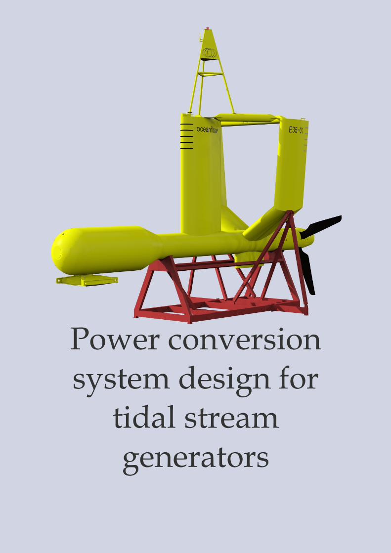
Power conversion system design for
tidal stream generators
This report describes the development of a power conversion system to capture energy with a floating horizontal axis tidal stream generator. All data provided in this report is for informational purposes only. Reproduction and citations are allowed after appropriate referencing to the full report. All copyrights reserved. http://www.optimacs.com/resources/reports/
Authors: Dr. Adrian West Dr. Mark Knös
Generating energy from ocean tidal flow is an emerging technology which
could contribute between 6GW to 12GW of clean power to the renewable
energy mix in the UK. Tidal flows are highly predictable and the power
generation cycle can be calculated years in advance. However, there are many
technical challenges that must be overcome before placing electrical generating
devices in the hostile marine environment. Tidal generators can be located in
the sea at 1km or more from the shore. They are susceptible to the effects of fast
tidal streams and must survive waves generated by storm activity. In addition,
a robust electrical transmission system is required to transmit generated power
back to the shore with minimal losses.
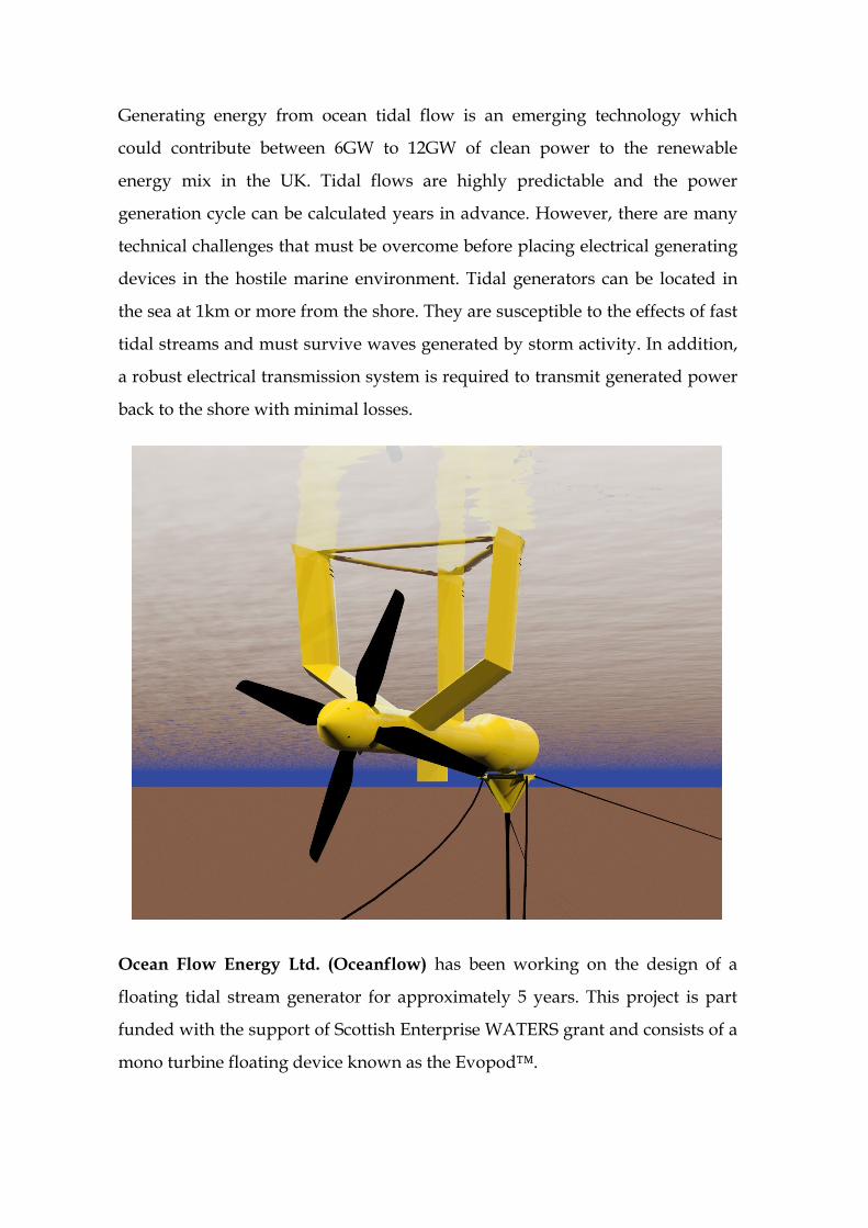
Ocean Flow Energy Ltd. (Oceanflow) has been working on the design of a
floating tidal stream generator for approximately 5 years. This project is part
funded with the support of Scottish Enterprise WATERS grant and consists of a
mono turbine floating device known as the Evopod™.

This patented device floats with most of the structure just below the surface of
the sea and is moored to the sea bed using cables. As the tide flows past the
submerged hull, the turbine turns and this generates electrical energy from an
on board generator. When the tide changes direction, the Evopod™ hull turns
around on a swivel in a similar way to a boat at anchor. Energy is then
generated on the return tidal flow in a similar way.
A prototype quarter-scale Evopod™ device is currently being constructed
which will generate approximately 25kW steady state in nominal tidal flows.
Using this prototype, the effect of the marine environment will be studied in
preparation for a full scale device which is expected to generate 1MW at
nominal tidal flow.
Approximately one year ago, Optima Control Solutions received the contract
to design and deliver the power conversion and transmission equipment for the
prototype Evopod™ tidal generator to be located in Sanda Sound, South
Kintyre, Scotland. A number of challenges were immediately apparent such as
how to deliver the power to the shore at minimal losses and also the fact that
some elements of the power conversion equipment would be within the
submerged hull and not accessible between the scheduled annual maintenance
slots. Other unknowns were the control strategies required to extract the
maximum power at all tidal flow states and how to protect the device during
wave activity caused by storm conditions.
After much discussion about power conversion equipment topologies, it was
decided to locate a fully regenerative power converter within Evopod’s hull.
This transmitted power via the mooring swivel slip rings to an umbilical cable
down to a sea bed located transformer. The 400V supply was boosted to a high
voltage and sent over a custom designed submerged 1km long cable to the
shore. This approach considerably reduced the cost of the sea bed cable and

minimised transmission losses. A step down transformer on the shore allowed
connection to the SSE local grid connection point.
Siemens was chosen as the preferred supplier for all power conversion and low
voltage switchgears. A 37kW Rotor induction generator was used, together
with Siemens SINAMICS S120 drive and active interface modules to generate
power at close to unity power factor with low harmonics. The generator was
operated in closed-loop vector mode in order to allow accurate control of
generator torque and speed. A Siemens three phase power supply was used to
generate all the on board auxiliary power supplies. This power supply, together
with the SINAMICS S120 drive allowed operation over the wide voltage range
expected due to transmission equipment impedances. All control equipment
was fitted into a dedicated equipment skid that will be fitted into the hull.
Local supplier Admagnetics was chosen to design and supply the two power
transformers. A rugged steel waterproof container was designed by Oceanflow
to house the sea bed transformer, together with special dry mate connectors for
the high voltage sub-sea cable and Evopod™ umbilical.
A major challenge still remained as to how to control the turbine to achieve
maximum generated power at all tidal flow states. Another problem was how
to protect the turbine from overload due to wave activity arising from storm
conditions. It was also difficult to experiment with different control strategies
with a deployed device due to the long time periods (6 hours) between similar
tidal flow rates. In order to overcome these difficulties, a two-pronged design
approach was used.
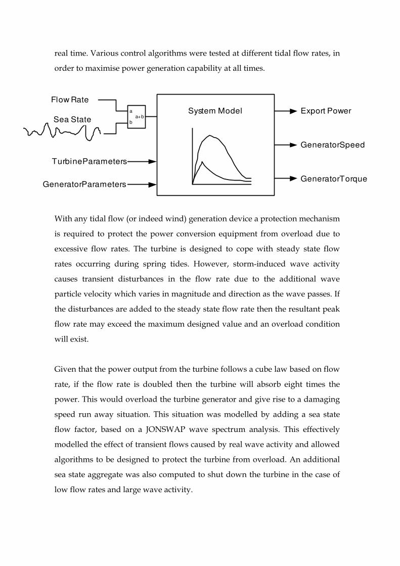
A full computer based simulation was designed by Optima using existing
models of a drive and motor, together with a new model of the turbine using
data supplied by Oceanflow. The software model was written within a
National Instruments LabVIEW programming environment and operated in
Flow Rate
Turbine Parameters
Generator Parameters
Export Power
Generator Speed
Generator Torque
System Modelaa+b
bSea State
real time. Various control algorithms were tested at different tidal flow rates, in
order to maximise power generation capability at all times.
With any tidal flow (or indeed wind) generation device a protection mechanism
is required to protect the power conversion equipment from overload due to
excessive flow rates. The turbine is designed to cope with steady state flow
rates occurring during spring tides. However, storm-induced wave activity
causes transient disturbances in the flow rate due to the additional wave
particle velocity which varies in magnitude and direction as the wave passes. If
the disturbances are added to the steady state flow rate then the resultant peak
flow rate may exceed the maximum designed value and an overload condition
will exist.
Given that the power output from the turbine follows a cube law based on flow
rate, if the flow rate is doubled then the turbine will absorb eight times the
power. This would overload the turbine generator and give rise to a damaging
speed run away situation. This situation was modelled by adding a sea state
flow factor, based on a JONSWAP wave spectrum analysis. This effectively
modelled the effect of transient flows caused by real wave activity and allowed
algorithms to be designed to protect the turbine from overload. An additional
sea state aggregate was also computed to shut down the turbine in the case of
low flow rates and large wave activity.

Generator PowerConversion
TestMotor
Set Torque
Set Flow
Torque
Flow
Laptop Test Drive
Export Power
Set Flow = 1.5mps
Evopod Electrical SystemTest Rig
Belt DriveTqAC
AC
The computer model produced outputs of export power, generator torque and
generator speed and these were trended to examine and refine system
behaviour for all expected flow rates and wave activity. With the control
algorithms completed, the second design approach was to construct a
dynamometer test rig to verify complete system operation.
In order to simulate the torque produced by the turbine a 37kW test motor was
connected to the generator using a belt drive. The test motor was supplied from
an inverter drive operating in closed loop vector torque control. Using the
software model, the expected torque value produced by the turbine was used to
supply the test drive torque set point. In addition, a simulated flow rate was
supplied by the model to the actual Evopod™ control equipment. The software
model was run on a lap top computer such that the test rig could be operated
under exactly the same flow and sea state conditions as the original software
simulation.
The two transformers were connected up with a test length of sub-sea cable,
together with the Optima-designed shore control panel, such that as much
electrical equipment as possible was in use for the load tests. The complete
length of sub-sea cable was not available for the tests but, due to the small
currents, cable core sizes and relatively short length in transmission terms, this
omission was considered to have a negligible effect.
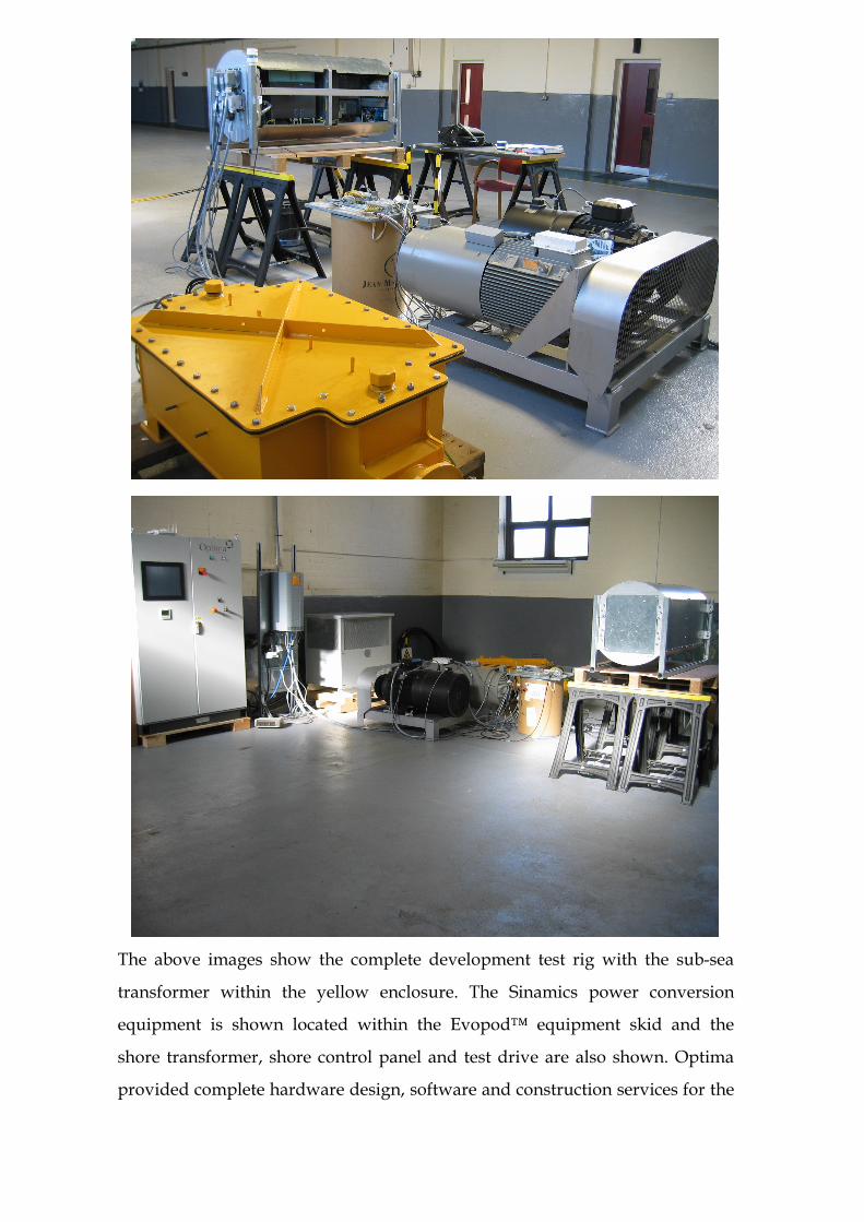
The above images show the complete development test rig with the sub-sea
transformer within the yellow enclosure. The Sinamics power conversion
equipment is shown located within the Evopod™ equipment skid and the
shore transformer, shore control panel and test drive are also shown. Optima
provided complete hardware design, software and construction services for the

shore panel and equipment skid. The modular system design has made testing
easier as it can completed away from Evopod’s hull.
The test rig was used extensively to further refine the control algorithms to
cope with all expected flow and sea states. Sufficient tests were performed to
prove operation and to provide confidence that the generator, power
conversion and transmission equipment would operate correctly when the tidal
generator is deployed. The power generated from the generator matched
exactly with the calculated values produced by Oceanflow using estimated
turbine characteristics. A turbine calibration algorithm was developed to allow
fine tuning of the control algorithms based on the actual turbine in real tidal
flow conditions.
A triple redundant communications system was designed to allow basic control
of the remote Evopod™ device. The extensive software running in a Siemens
PLC within the equipment skid is responsible for complete control of the
generator, independently of the communications link. A comprehensive alarm
system is used to shut down the generator in case of equipment failure or
extreme operating conditions.
Since this is a development prototype, a comprehensive data logging and
trending system was designed to collect all operational data such as export
power, speed, torque, equipment temperatures and mooring line tensions etc.
via the communications link. A universal marine GPS sensor is used to measure
the geographic position, pitch, roll, compass heading and weather information
for subsequent control and data logging. A tri-axial accelerometer is used to
measure dynamic motion.
The data collection system is based on the InfoServe365 data collection platform
which allows historical and real time data to be collected and displayed from
any location using web browser technologies. The data logging system was
integrated into a custom designed, tag based SCADA system based on the

National Instruments LabVIEW programming environment which is ideally
suited for the application.
In conclusion, the extensive use of software simulation and a comprehensive
dynamometer test rig has ensured that the overall hardware and software
design has been tested to a level where minimal commissioning will be
required during sea trials of the tidal generator. An additional benefit is that the
on board equipment has been used sufficiently to expose any early life failures
and provide a more reliable solution. Considering the marine operations costs
involved during recovery and deployment of the tidal generator, the additional
design costs incurred during this design approach are negligible.

References:
Ocean Flow Energy Ltd http://www.oceanflowenergy.com
Optima Control Solutions Ltd http://www.optimacs.com
Siemens Automation
Technologies http://www.automation.siemens.com
Admagnetics http://www.admagnetics.co.uk
InfoServe365 Ltd http://www.infoserve365.com
National Instruments UK http://uk.ni.com