power distribution module - graco · power distribution module for use with hfr, vrm, and vpm...
TRANSCRIPT
3A0239FEN
Instructions - Parts
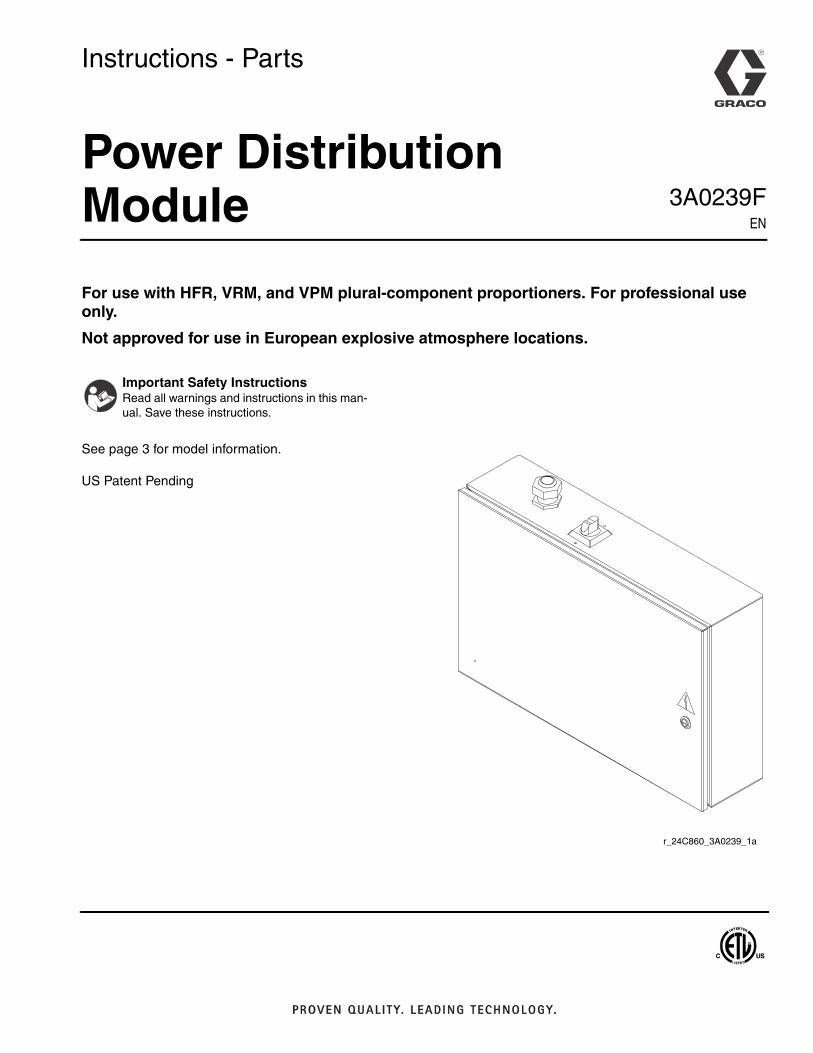
Power Distribution Module
For use with HFR, VRM, and VPM plural-component proportioners. For professional use only.
Not approved for use in European explosive atmosphere locations.
See page 3 for model information.
US Patent Pending
Important Safety InstructionsRead all warnings and instructions in this man-ual. Save these instructions.
r_24C860_3A0239_1a

2 3A0239F
ContentsModels . . . . . . . . . . . . . . . . . . . . . . . . . . . . . . . . . . . 3Warnings . . . . . . . . . . . . . . . . . . . . . . . . . . . . . . . . . 4Troubleshooting . . . . . . . . . . . . . . . . . . . . . . . . . . . . 5Repair . . . . . . . . . . . . . . . . . . . . . . . . . . . . . . . . . . . . 6
Replace Power Supply . . . . . . . . . . . . . . . . . . . . 6Replace Circuit Breaker . . . . . . . . . . . . . . . . . . . 6
Electrical Schematics . . . . . . . . . . . . . . . . . . . . . . . 7Parts . . . . . . . . . . . . . . . . . . . . . . . . . . . . . . . . . . . . 20
HFR Power Distribution Modules . . . . . . . . . . . 20VRM Power Distribution Modules . . . . . . . . . . . 23VPM Power Distribution Modules . . . . . . . . . . . 26
Graco Standard Warranty . . . . . . . . . . . . . . . . . . . 30Graco Information . . . . . . . . . . . . . . . . . . . . . . . . 30
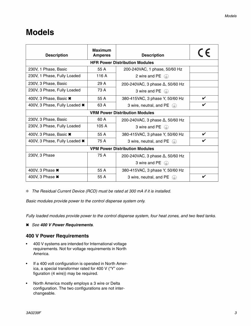
Models
3A0239F 3
Models
The Residual Current Device (RCD) must be rated at 300 mA if it is installed.
Basic modules provide power to the control dispense system only.
Fully loaded modules provide power to the control dispense system, four heat zones, and two feed tanks.
See 400 V Power Requirements.
400 V Power Requirements
• 400 V systems are intended for International voltage requirements. Not for voltage requirements in North America.
• If a 400 volt configuration is operated in North Amer-ica, a special transformer rated for 400 V (“Y” con-figuration (4 wire)) may be required.
• North America mostly employs a 3 wire or Delta configuration. The two configurations are not inter-changeable.
DescriptionMaximum Amperes Description
HFR Power Distribution Modules
230V, 1 Phase, Basic 55 A 200-240VAC, 1 phase, 50/60 Hz
2 wire and PE 230V, 1 Phase, Fully Loaded 116 A
230V, 3 Phase, Basic 29 A 200-240VAC, 3 phase Δ, 50/60 Hz
3 wire and PE 230V, 3 Phase, Fully Loaded 73 A
400V, 3 Phase, Basic 55 A 380-415VAC, 3 phase Y, 50/60 Hz
3 wire, neutral, and PE
400V, 3 Phase, Fully Loaded 63 A
VRM Power Distribution Modules
230V, 3 Phase, Basic 60 A 200-240VAC, 3 phase Δ, 50/60 Hz
3 wire and PE 230V, 3 Phase, Fully Loaded 105 A
400V, 3 Phase, Basic 55 A 380-415VAC, 3 phase Y, 50/60 Hz
3 wire, neutral, and PE
400V, 3 Phase, Fully Loaded 75 A
VPM Power Distribution Modules
230V, 3 Phase 75 A 200-240VAC, 3 phase Δ, 50/60 Hz
3 wire and PE
400V, 3 Phase 55 A 380-415VAC, 3 phase Y, 50/60 Hz
3 wire, neutral, and PE 400V, 3 Phase 55 A
Warnings
4 3A0239F
WarningsThe following warnings are for the setup, use, grounding, maintenance, and repair of this equipment. The exclama-tion point symbol alerts you to a general warning and the hazard symbol refers to procedure-specific risk. Refer back to these warnings. Additional, product-specific warnings may be found throughout the body of this manual where applicable.
WARNINGELECTRIC SHOCK HAZARD This equipment must be grounded. Improper grounding, setup, or usage of the system can cause electric shock.• Turn off and disconnect power at main switch before disconnecting any cables and before servicing
equipment.• Connect only to grounded power source.• All electrical wiring must be done by a qualified electrician and comply with all local codes and
regulations.
EQUIPMENT MISUSE HAZARD Misuse can cause death or serious injury.• Do not operate the unit when fatigued or under the influence of drugs or alcohol.• Do not exceed the maximum working pressure or temperature rating of the lowest rated system
component. See Technical Data in all equipment manuals.• Do not leave the work area while equipment is energized or under pressure. Turn off all equipment
and follow the Pressure Relief Procedure in this manual when equipment is not in use.• Check equipment daily. Repair or replace worn or damaged parts immediately with genuine manu-
facturer’s replacement parts only.• Do not alter or modify equipment.• Use equipment only for its intended purpose. Call your distributor for information.• Route hoses and cables away from traffic areas, sharp edges, moving parts, and hot surfaces.• Do not kink or over bend hoses or use hoses to pull equipment.• Keep children and animals away from work area.• Comply with all applicable safety regulations.
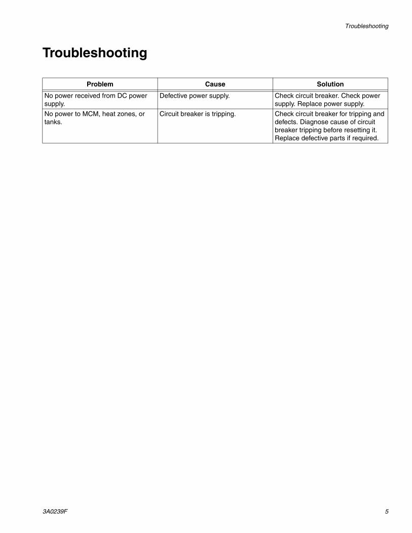
Troubleshooting
3A0239F 5
Troubleshooting
Problem Cause Solution
No power received from DC power supply.
Defective power supply. Check circuit breaker. Check power supply. Replace power supply.
No power to MCM, heat zones, or tanks.
Circuit breaker is tripping. Check circuit breaker for tripping and defects. Diagnose cause of circuit breaker tripping before resetting it. Replace defective parts if required.
Repair
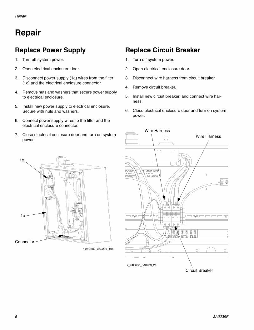
6 3A0239F
Repair
Replace Power Supply1. Turn off system power.
2. Open electrical enclosure door.
3. Disconnect power supply (1a) wires from the filter (1c) and the electrical enclosure connector.
4. Remove nuts and washers that secure power supply to electrical enclosure.
5. Install new power supply to electrical enclosure. Secure with nuts and washers.
6. Connect power supply wires to the filter and the electrical enclosure connector.
7. Close electrical enclosure door and turn on system power.
Replace Circuit Breaker1. Turn off system power.
2. Open electrical enclosure door.
3. Disconnect wire harness from circuit breaker.
4. Remove circuit breaker.
5. Install new circuit breaker, and connect wire har-ness.
6. Close electrical enclosure door and turn on system power.
1c
Connector
r_24C680_3A0239_10a
1a
Wire HarnessWire Harness
Circuit Breakerr_24C686_3A0239_2a
Electrical Schematics
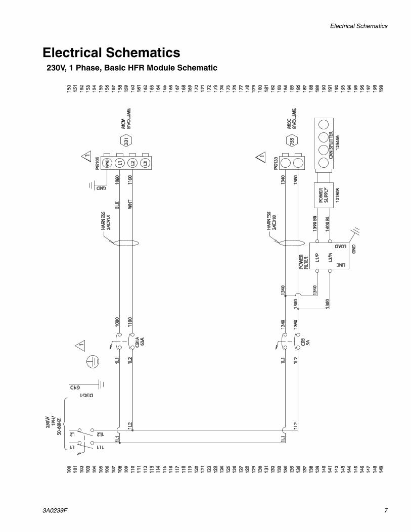
3A0239F 7
Electrical Schematics230V, 1 Phase, Basic HFR Module Schematic
Electrical Schematics
8 3A0239F
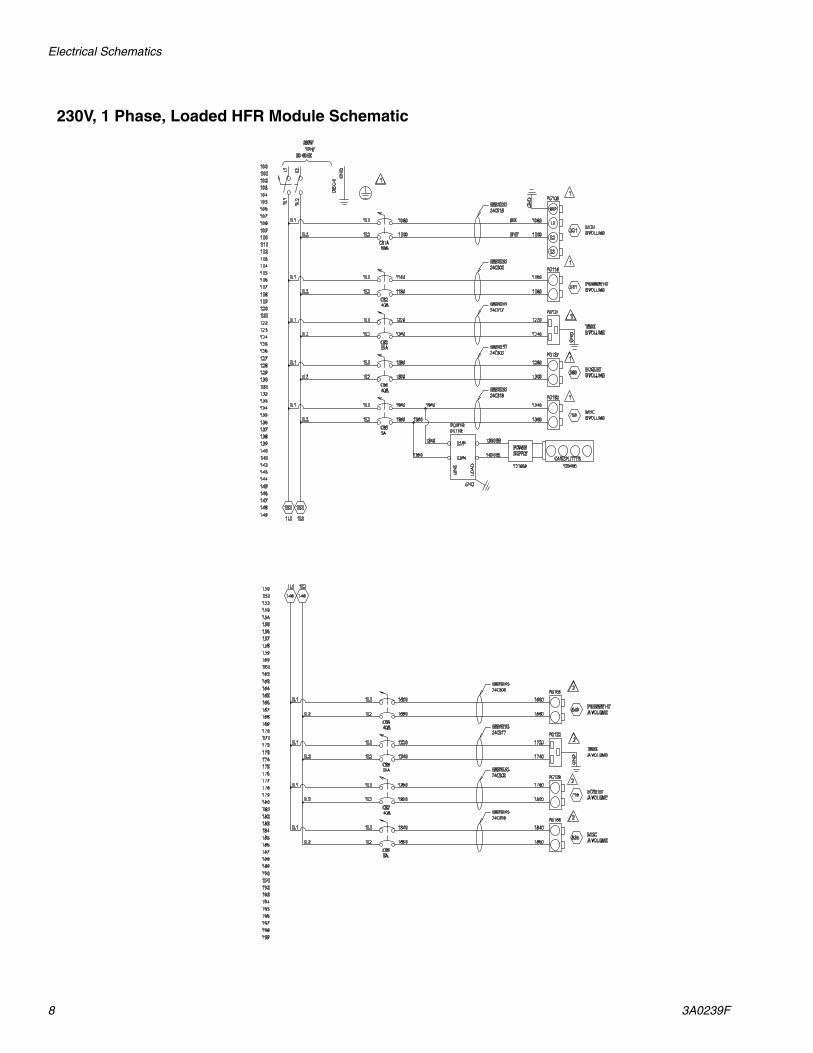
230V, 1 Phase, Loaded HFR Module Schematic

Electrical Schematics
3A0239F 9
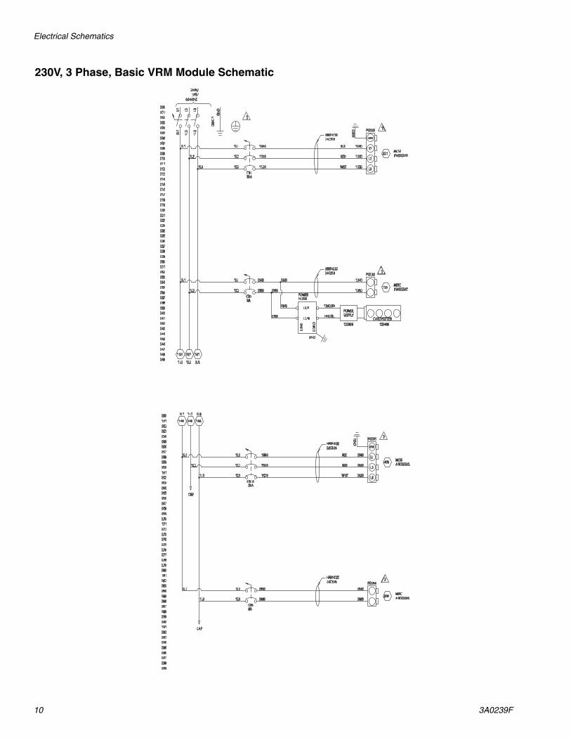
230V, 3 Phase, Basic HFR Module Schematic
Electrical Schematics
10 3A0239F
230V, 3 Phase, Basic VRM Module Schematic
Electrical Schematics
3A0239F 11
230V, 3 Phase, Loaded HFR Module Schematic

Electrical Schematics
12 3A0239F
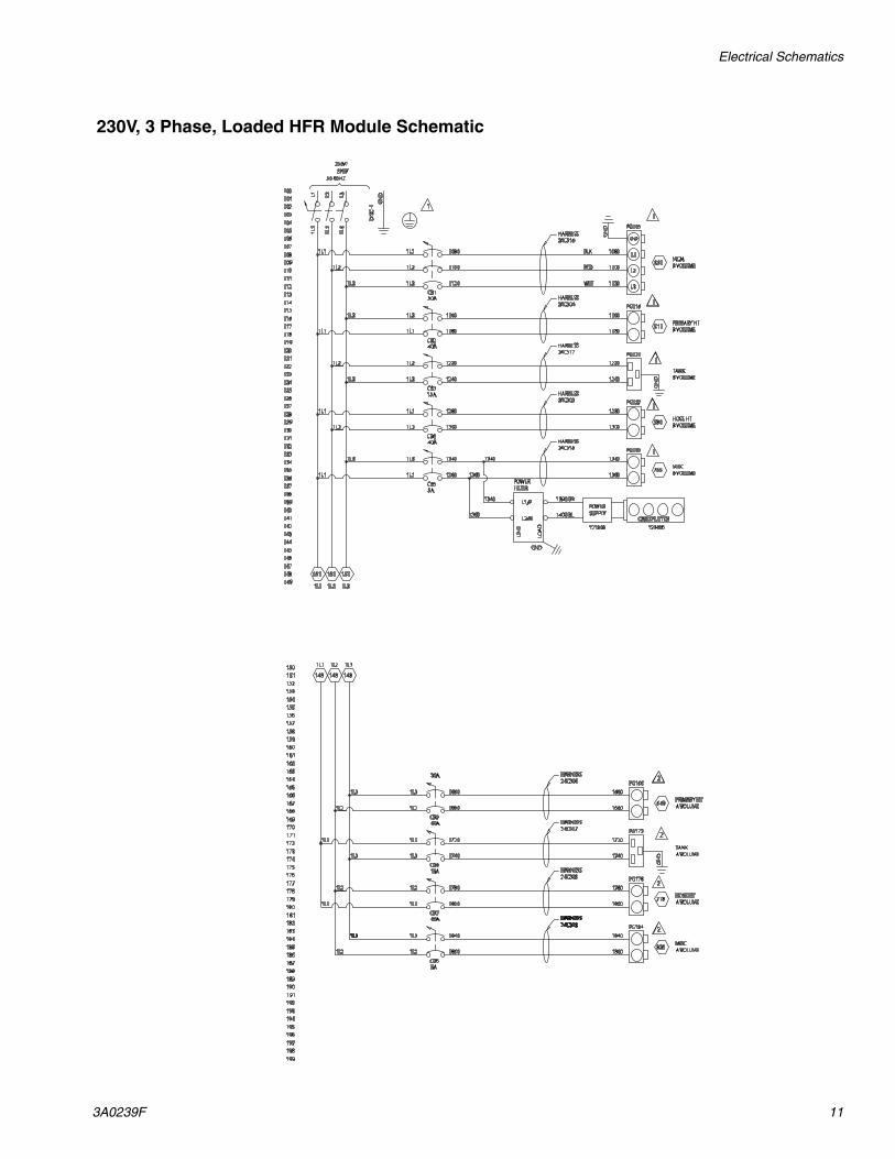
230V, 3 Phase, Loaded VRM Module Schematic
Electrical Schematics
3A0239F 13
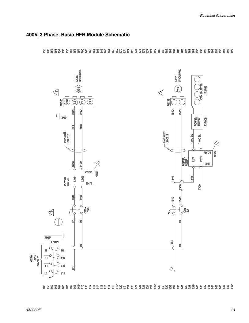
400V, 3 Phase, Basic HFR Module Schematic
Electrical Schematics
14 3A0239F
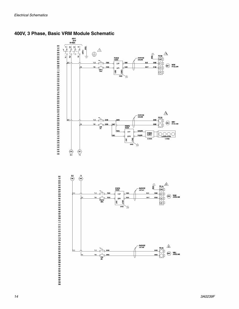
400V, 3 Phase, Basic VRM Module Schematic

Electrical Schematics
3A0239F 15
400V, 3 Phase, Loaded HFR Module Schematic
Electrical Schematics
16 3A0239F
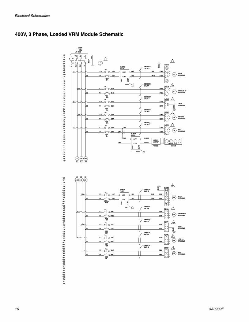
400V, 3 Phase, Loaded VRM Module Schematic
Electrical Schematics
3A0239F 17
190
199
197
195
192
160
188
186
184
182
180
178
176
174
172
170
168
164
166
162
158
156
154
152
150
191
198
194
196
193
161
189
187
185
183
181
179
177
175
173
171
169
165
167
163
159
157
155
153
151 148
1L3
148
1L2
PRIMARY HTA VOLUME
CB9
PG166
649
MISCA VOLUME
CB6
PG184
824
HARNESS
HARNESS
HARNESS
20A
5A
148
1L1
1L11L1
1L21L2
1L31L3
CB1030A
1L31L3
1L11L1
1L21L2
1L1 1660
1680
1660
1680
1840
1860
1840
1860
MCMA VOLUME
PG156
1580
1600469
GN
D
L1
GND
L2
L31620
1580
1600
1620
2
2
2
BLK
RED
WHT
1L1
140
149
147
145
142
110
138
136
134
132
130
128
126
124
122
120
118
114
116
112
108
106
104
102
100
141
148
144
146
143
111
139
137
135
133
131
129
127
125
123
121
119
115
117
113
109
107
105
103
101
50-60HZ3PH/
230V/
DIS
C-1
L31L
3
L21L
2
L11L
1
GN
D
151
1L3
151
1L2
TANKVOLUME
CB3
PG121
GN
D
PRIMARY HTB VOLUME
CB2
PG116
511
MISCB VOLUME
CB5
PG133
755
HARNESS
HARNESS
HARNESS
20A
15A
5A
1L11L1
1L21L2
151
1L1
1L31L3
CB130A
1L21L2
1L3
1L31L3
1L11L1
1L1
1L2
1L1
1220
1240
1220
1240
1160
1180
1160
1180
1340
1360
1340
1360
MCMB VOLUME
PG105
1080
1100331
GN
D
L1
GND
L2
L31120
HARNESS
1080
1100
1120
1360
1340
1340
1360POWERSUPPLY
121808 123466CAN SPLITTER
GND
POWERFILTER
L1/P
L2/N
LOA
D
LIN
E
1390 BR
1400 BL
1
1
1
1
1
BLK
RED
WHT
1L3
1L2
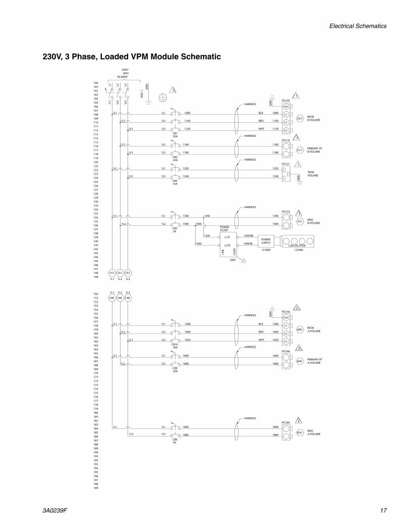
230V, 3 Phase, Loaded VPM Module Schematic
Electrical Schematics
18 3A0239F
190
199
197
195
192
160
188
186
184
182
180
178
176
174
172
170
168
164
166
162
158
156
154
152
150
191
198
194
196
193
161
189
187
185
183
181
179
177
175
173
171
169
165
167
163
159
157
155
153
151 148
1N
148
1L3
148
1L2
PRIMARY HTA VOLUME
CB9
1660
1N1N 1680
PG1661660
1680649
1L2MISCA VOLUME
CB6
1840
1N1N 1860
PG1841840
1860824
1L3MCMA VOLUME
CB10A
1L3
1N1N
PG156
1580
1600469
GN
D
HARNESS
HARNESS
HARNESS
20A
63A
5A
L1
GND
L2
L3
1580
1600
1L2 1L2
2
2
2
BLK
WHT
1L2
140
149
147
145
142
110
138
136
134
132
130
128
126
124
122
120
118
114
116
112
108
106
104
102
100
141
148
144
146
143
111
139
137
135
133
131
129
127
125
123
121
119
115
117
113
109
107
105
103
101
151
50-60HZ3PH/
400V/
DIS
C-1
L31L
3
L21L
2
L11L
1
N1N
GN
D
1N
151
1L3
151
1L2
1L2TANKB VOLUME
CB3
1220
1N1N 1240
PG121
GN
D
1220
1240
PRIMARY HTB VOLUME
CB2
1160
1N1N 1180
PG1161160
1180511
MISCB VOLUME
CB5
1340
1N1N 1360
PG1331340
1360755
1L1MCMB VOLUME
CB1A
1N1N
PG105
1080
1100331
GN
D
HARNESS
HARNESS
HARNESS
20A
63A
15A
5A
L1
GND
L2
L3
HARNESS
1080
1100
1360
1340
1340
1360POWERSUPPLY
121808 123466CAN SPLITTER
GND
POWERFILTER
L1/P
L2/N
LOA
D
LIN
E
1390 BR
1400 BL
1L2 1L2
1L2
1
1
1
1
1
BLK
WHT
1L2
1L1
1L2
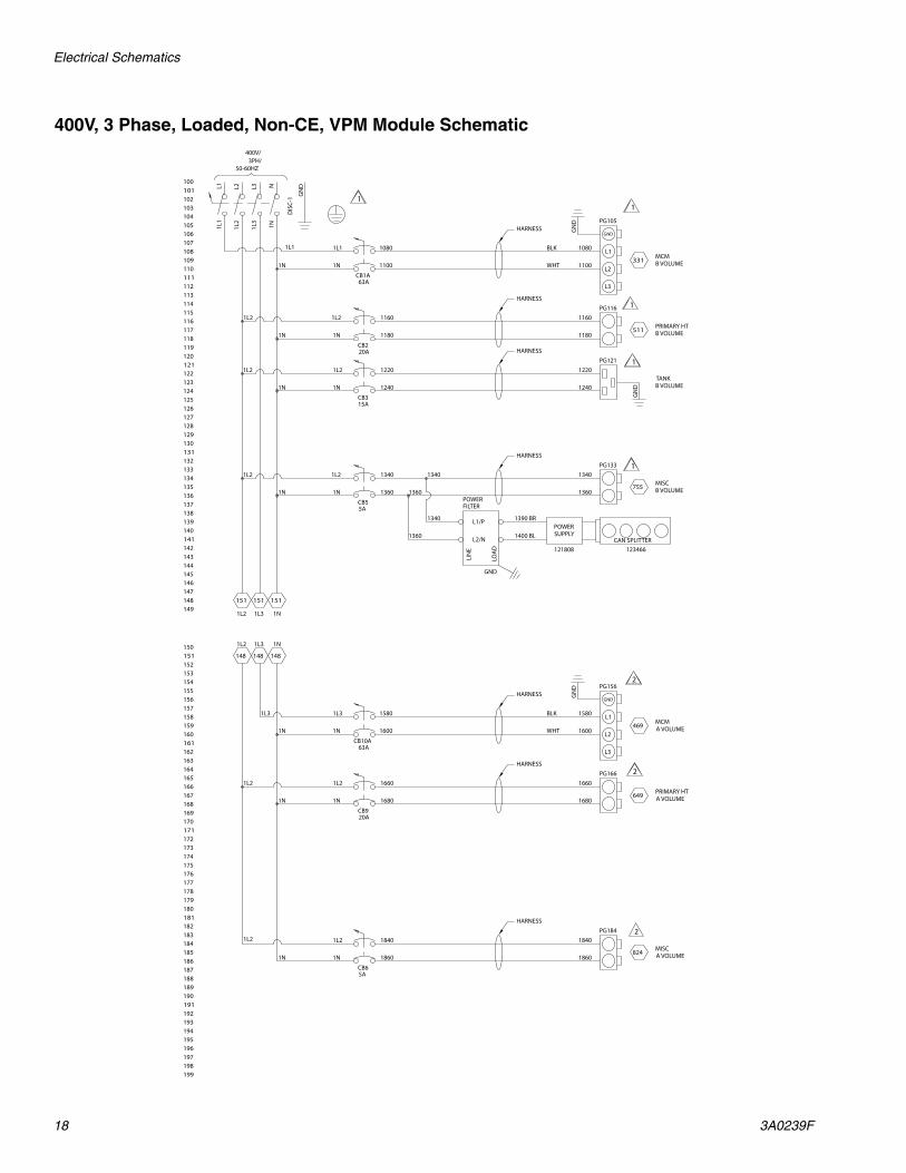
400V, 3 Phase, Loaded, Non-CE, VPM Module Schematic
Electrical Schematics
3A0239F 19
190
199
197
195
192
160
188
186
184
182
180
178
176
174
172
170
168
164
166
162
158
156
154
152
150
191
198
194
196
193
161
189
187
185
183
181
179
177
175
173
171
169
165
167
163
159
157
155
153
151 148
1N
148
1L3
148
1L2
PRIMARY HTA VOLUME
CB9
1660
1N1N 1680
PG1661660
1680649
1L2MISCA VOLUME
CB6
1840
1N1N 1860
PG1841840
1860824
1L3MCMA VOLUME
CB10A
1L3
1N1N
PG156
1580
1600469
GN
D
HARNESS
HARNESS
HARNESS
20A
63A
5A
L1
GND
L2
L3
1581
1601
GND
POWERFILTER
L1/P
L2/N
LOA
D
LIN
E
1580
1600
1L2 1L2
2
2
2
BLK
WHT
1L2
140
149
147
145
142
110
138
136
134
132
130
128
126
124
122
120
118
114
116
112
108
106
104
102
100
141
148
144
146
143
111
139
137
135
133
131
129
127
125
123
121
119
115
117
113
109
107
105
103
101
151
50-60HZ3PH/
400V/
DIS
C-1
L31L
3
L21L
2
L11L
1
N1N
GN
D
1N
151
1L3
151
1L2
1L2TANKB VOLUME
CB3
1220
1N1N 1240
PG121
GN
D
1220
1240
PRIMARY HTB VOLUME
CB2
1160
1N1N 1180
PG1161160
1180511
MISCB VOLUME
CB5
1340
1N1N 1360
PG1331340
1360755
1L1MCMB VOLUME
CB1A
1N1N
PG105
1080
1100331
GN
D
HARNESS
HARNESS
HARNESS
20A
63A
15A
5A
L1
GND
L2
L3
HARNESS
1081
1101
GND
POWERFILTER
L1/P
L2/N
LOA
D
LIN
E
1080
1100
1360
1340
1340
1360POWERSUPPLY
121808 123466CAN SPLITTER
GND
POWERFILTER
L1/P
L2/NLO
AD
LIN
E1390 BR
1400 BL
1L2 1L2
1L2
1
1
1
1
1
BLK
WHT
1L2
1L1
1L2
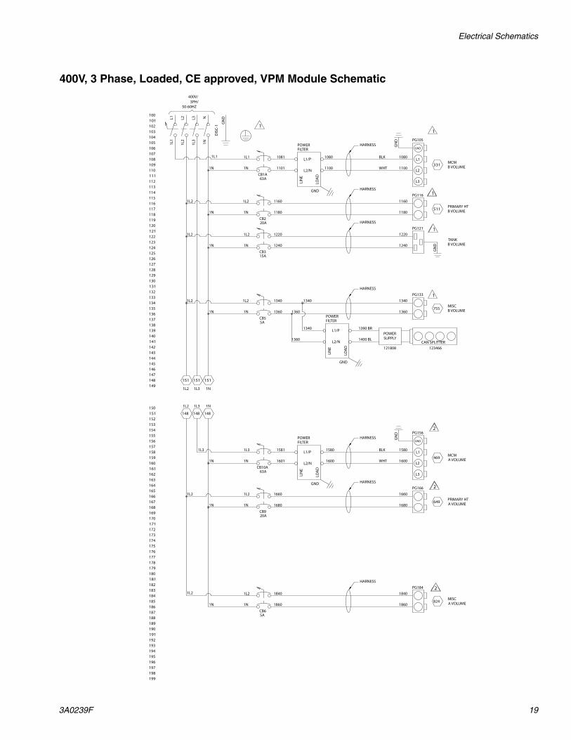
400V, 3 Phase, Loaded, CE approved, VPM Module Schematic
Parts
20 3A0239F
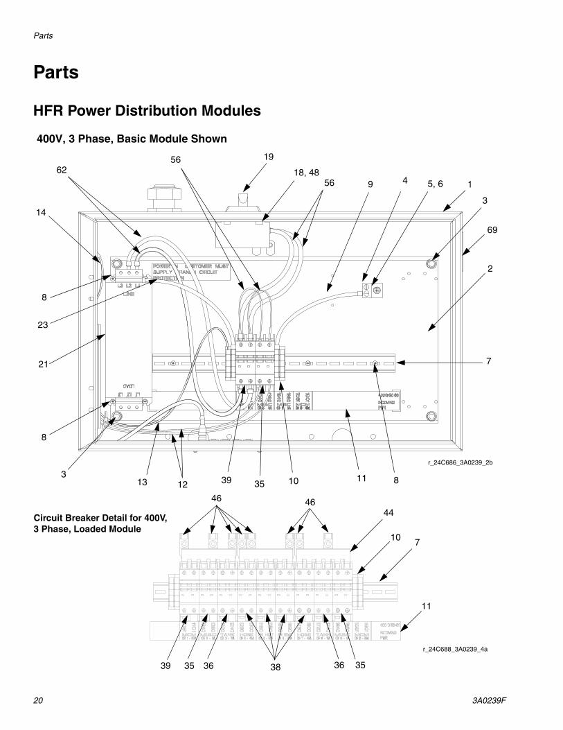
Parts
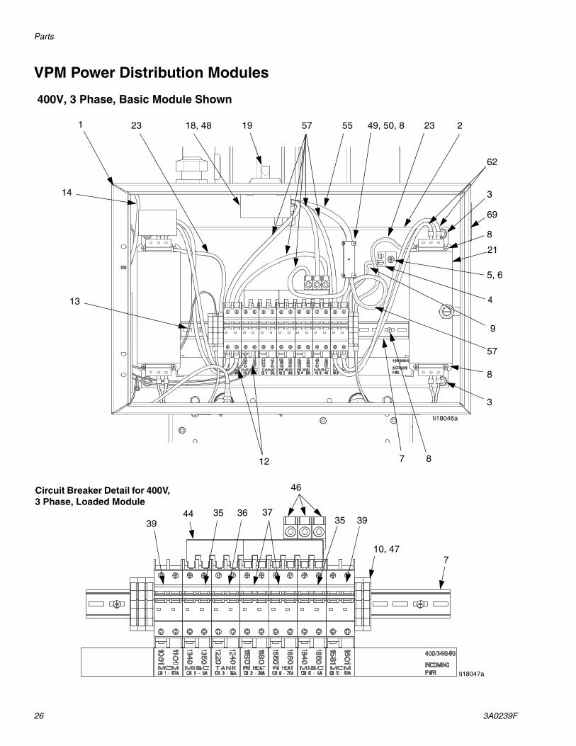
HFR Power Distribution Modules
r_24C686_3A0239_2b
400V, 3 Phase, Basic Module Shown
r_24C688_3A0239_4a
Circuit Breaker Detail for 400V, 3 Phase, Loaded Module
19
18, 4856 4
11 8
5, 69
7
3
1
2
8
313 12 39 35 10
21
5662
14
8
23
710
44
35 36 38 36 3539
46 46
11
69
Parts
3A0239F 21
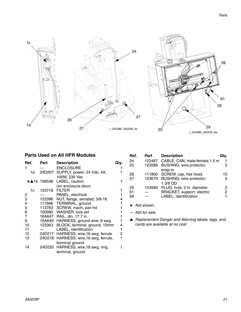
Parts Used on All HFR Modules
Not shown.
--- Not for sale.
Replacement Danger and Warning labels, tags, and cards are available at no cost.
r_24C680_3A0239_5ar_24C680_3A0239_6a
24
26
61
26
292527
2027
1c
1a
Ref. Part Description Qty.1 --- ENCLOSURE 1
1a 24D207 SUPPLY, power; 24 Vdc, 4A, 100W, 230 Vac
1
1b 196548 LABEL, caution (on enclosure door)
1
1c 123718 FILTER 12 --- PANEL, electrical 13 123396 NUT, flange, serrated; 3/8-16 44 117666 TERMINAL, ground 15 113783 SCREW, mach, pan hd 16 100985 WASHER, lock ext 17 16A647 RAIL, din, 17.7 in. 19 16A649 HARNESS, ground wire; 8 awg 110 123363 BLOCK, terminal, ground, 10mm 411 --- LABEL, identification 112 24D217 HARNESS, wire,16 awg, ferrule 213 24D218 HARNESS, wire,16 awg, ferrule,
terminal ground1
14 24D220 HARNESS, wire,18 awg, ring, terminal, ground
1
24 122487 CABLE, CAN, male-female,1.5 m 125 123589 BUSHING, wire protector,
snap-in2
26 111800 SCREW, cap, hex head 1027 123679 BUSHING, wire protector;
1 3/8 OD3
29 123590 PLUG, hole; 2 in. diameter 261 --- BRACKET, support, electric 269 --- LABEL, identification 1
Ref. Part Description Qty.
Parts
22 3A0239F
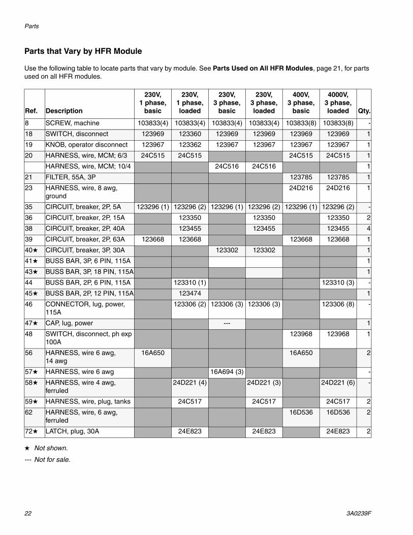
Parts that Vary by HFR Module
Use the following table to locate parts that vary by module. See Parts Used on All HFR Modules, page 21, for parts used on all HFR modules.
Not shown.
--- Not for sale.
Ref. Description
230V, 1 phase,
basic
230V, 1 phase, loaded
230V, 3 phase,
basic
230V, 3 phase, loaded
400V, 3 phase,
basic
4000V, 3 phase, loaded Qty.
8 SCREW, machine 103833(4) 103833(4) 103833(4) 103833(4) 103833(8) 103833(8) -
18 SWITCH, disconnect 123969 123360 123969 123969 123969 123969 1
19 KNOB, operator disconnect 123967 123362 123967 123967 123967 123967 1
20 HARNESS, wire, MCM; 6/3 24C515 24C515 24C515 24C515 1
HARNESS, wire, MCM; 10/4 24C516 24C516 1
21 FILTER, 55A, 3P 123785 123785 1
23 HARNESS, wire, 8 awg, ground
24D216 24D216 1
35 CIRCUIT, breaker, 2P, 5A 123296 (1) 123296 (2) 123296 (1) 123296 (2) 123296 (1) 123296 (2) -
36 CIRCUIT, breaker, 2P, 15A 123350 123350 123350 2
38 CIRCUIT, breaker, 2P, 40A 123455 123455 123455 4
39 CIRCUIT, breaker, 2P, 63A 123668 123668 123668 123668 1
40 CIRCUIT, breaker, 3P, 30A 123302 123302 1
41 BUSS BAR, 3P, 6 PIN, 115A 1
43 BUSS BAR, 3P, 18 PIN, 115A 1
44 BUSS BAR, 2P, 6 PIN, 115A 123310 (1) 123310 (3) -
45 BUSS BAR, 2P, 12 PIN, 115A 123474 1
46 CONNECTOR, lug, power, 115A
123306 (2) 123306 (3) 123306 (3) 123306 (8) -
47 CAP, lug, power --- 1
48 SWITCH, disconnect, ph exp 100A
123968 123968 1
56 HARNESS, wire 6 awg, 14 awg
16A650 16A650 2
57 HARNESS, wire 6 awg 16A694 (3) -
58 HARNESS, wire 4 awg, ferruled
24D221 (4) 24D221 (3) 24D221 (6) -
59 HARNESS, wire, plug, tanks 24C517 24C517 24C517 2
62 HARNESS, wire, 6 awg, ferruled
16D536 16D536 2
72 LATCH, plug, 30A 24E823 24E823 24E823 2

Parts
3A0239F 23
VRM Power Distribution Modules
400V, 3 Phase, Basic Module Shown
r_24C687_3A0239_3a
r_24C689_3A0239_7a
Circuit Breaker Detail for 400V, 3 Phase, Loaded Module
1918, 48
56
4
11 8
5, 623
7
3
1
2
8
313 12 39 35 10
21
5657
14
23
7
10
44
35 36 38 36 3539
46 46
11
21
9
8, 49, 5055
39
69

Parts
24 3A0239F
Parts Used on All VRM Modules
Not shown.
--- Not for sale.
Replacement Danger and Warning labels, tags, and cards are available at no cost.
r_24C683_3A0239_9ar_24C683_3A0239_8a
2663, 64, 65
27
26 25 29
27
28
20
24
20
1c
1a
Ref. Part Description Qty.1 --- ENCLOSURE 1
1a 24D207 SUPPLY, power; 24 Vdc, 4A, 100W, 230 Vac
1
1b 196548 LABEL, caution (on enclosure door)
1
1c 123718 FILTER 12 --- PANEL, electrical 13 123396 NUT, flange, serrated; 3/8-16 44 117666 TERMINAL, ground 15 113783 SCREW, mach, pan hd 16 100985 WASHER, lock ext 17 16A647 RAIL, din, 17.7 in. 19 16A649 HARNESS, ground wire; 8 awg 110 123363 BLOCK, terminal, ground, 10mm 411 --- LABEL, identification 112 24D217 HARNESS, wire,16 awg, ferrule 213 24D218 HARNESS, wire,16 awg, ferrule,
terminal ground1
14 24D220 HARNESS, wire,18 awg, ring, terminal, ground
1
24 122487 CABLE, CAN, male-female;1.5 m
2
25 123589 BUSHING, wire protector, snap-in
2
26 111800 SCREW, cap, hex head 1027 123679 BUSHING, wire protector;
1 3/8 OD3
28 123398 PLUG, hole,1.5 in. diameter 229 123590 PLUG, hole; 2 in. diameter 235 123296 CIRCUIT, breaker, 2P, 5A 263 24C477 BRACE, wireway, divided 164 24C478 COVER, wireway 165 102040 NUT, lock, hex 266 124128 BUSHING, wire protector 169 --- LABEL, identification 1
Ref. Part Description Qty.
Parts
3A0239F 25
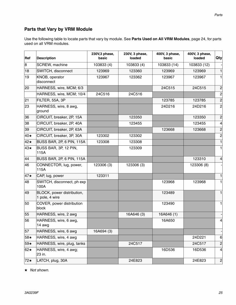
Parts that Vary by VRM Module
Use the following table to locate parts that vary by module. See Parts Used on All VRM Modules, page 24, for parts used on all VRM modules.
Not shown.
Ref Description230V,3 phase,
basic230V, 3 phase,
loaded400V, 3 phase,
basic400V, 3 phase,
loaded Qty
8 SCREW, machine 103833 (4) 103833 (4) 103833 (14) 103833 (12) -
18 SWITCH, disconnect 123969 123360 123969 123969 1
19 KNOB, operator disconnect
123967 123362 123967 123967 1
20 HARNESS, wire, MCM; 6/3 24C515 24C515 2
HARNESS, wire, MCM; 10/4 24C516 24C516 2
21 FILTER, 55A, 3P 123785 123785 2
23 HARNESS, wire, 8 awg, ground
24D216 24D216 2
36 CIRCUIT, breaker, 2P, 15A 123350 123350 2
38 CIRCUIT, breaker, 2P, 40A 123455 123455 4
39 CIRCUIT, breaker, 2P, 63A 123668 123668 2
40 CIRCUIT, breaker, 3P, 30A 123302 123302 2
42 BUSS BAR, 2P, 6 PIN, 115A 123308 123308 1
43 BUSS BAR, 3P, 12 PIN, 115A
123309 1
44 BUSS BAR, 2P, 6 PIN, 115A 123310 4
46 CONNECTOR, lug, power, 115A
123306 (3) 123306 (3) 123306 (8) -
47 CAP, lug, power 123311 1
48 SWITCH, disconnect, ph exp 100A
123968 123968 1
49 BLOCK, power distribution, 1 pole, 4 wire
123489 1
50 COVER, power distribution block
123490 1
55 HARNESS, wire, 2 awg 16A646 (3) 16A646 (1) -
56 HARNESS, wire, 6 awg, 14 awg
16A650 4
57 HARNESS, wire, 6 awg 16A694 (3) -
58 HARNESS, wire, 4 awg 24D221 6
59 HARNESS, wire, plug, tanks 24C517 24C517 2
62 HARNESS, wire, 4 awg; 23 in.
16D536 16D536 4
72 LATCH, plug, 30A 24E823 24E823 2
Parts
26 3A0239F
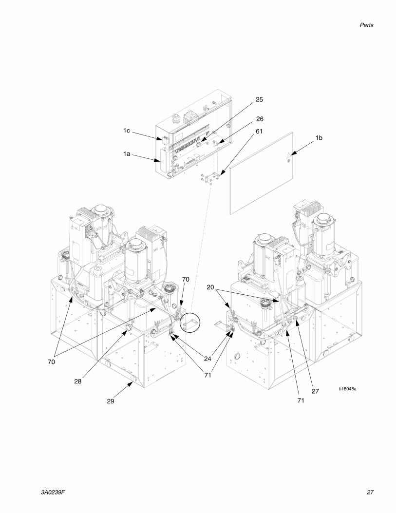
VPM Power Distribution Modules
400V, 3 Phase, Basic Module Shown
Circuit Breaker Detail for 400V, 3 Phase, Loaded Module
23
46
710, 47
393544 373635
39
18, 48 19 57 55 49, 50, 8 23
62
3
8
21
9
57
8
3
12
13
2
4
5, 6
87
1
69
14
ti18047a
ti18046a
Parts
3A0239F 27
ti18048a
25
26
29
61
28
27
24
71
71
2070
70
1b1c
1a

Parts
28 3A0239F
Parts Used on All VPM Modules
Not shown.
--- Not for sale.
Replacement Danger and Warning labels, tags, and cards are available at no cost.
Parts that Vary by VPM Module
Use the following table to locate parts that vary by module. See Parts Used on All VPM Modules, page 28, for parts used on all VPM modules.
Ref. Part Description Qty1 --- ENCLOSURE 1
1a 24D207 SUPPLY, power; 24Vdc, 4A, 100W, 230 Vac
1
1b 196548 LABEL, caution (on enclosure door)
1
1c 123718 FILTER 12 16A360 PANEL, electrical 13 123396 NUT, flange, serrated; 3/8-16 44 117666 TERMINAL, ground 15 113783 SCREW, mach, pan hd 16 100985 WASHER, lock ext 17 16A647 RAIL, din, 17.7 in. 18 103833 SCREW, mach, crbh 69 16A649 HARNESS, ground wire; 8 awg 110 123363 BLOCK, terminal, ground, 10mm 512 24D217 HARNESS, wire, 16 awg, ferrule 213 24D218 HARNESS, wire, 16 awg, ferrule,
terminal ground1
14 24D220 HARNESS, wire, 18 awg, ring, terminal, ground
1
18 123969 SWITCH, disconnect 119 123967 KNOB, operator disconnect 124 122487 CABLE, can, male-female, 1.5 m 125 123589 BUSHING, wire protector, snap-in 426 111800 SCREW, cap, hex hd 1027 123679 BUSHING, wire protector, snap-in 628 123398 PLUG, hole, 1 1/2 diameter 629 123590 PLUG, hole, 2 in. diameter 435 123296 CIRCUIT, breaker, 2P, 5A 236 123350 CIRCUIT, breaker, 2P, 15A 137 123298 CIRCUIT, breaker, 2P, 20A 246 123306 CONNECTOR, lug, power, 115A 361 --- BRACKET, support, electric 269 --- LABEL, identification 171 123652 CABLE, can, male / female 3.5m 1
Ref. Part Description Qty
Ref. Description
400V, 3 phase,non-CE
230V, 3 phase
400v, 3 phase,
CE Qty.
20 HARNESS, wire, MCM 24E624 24E625 24E624 1
21 FILTER, 55A, 3P 123785 2
23 HARNESS, wire, 8 awg, ground 24D216 2
39 CIRCUIT, breaker, 2P, 63A 123688 123668 2
CIRCUIT, breaker, 3P, 30A 123302 2
42 BUSS BAR, 3P, 12 PIN, 115A 123308 1
44 BUSS BAR, 3P, 18 PIN, 115A 123309 1
BUSS BAR, 2P, 6 PIN, 115A 123310 123310 2
47 CAP, lug, power (not shown) 123311 1
48 SWITCH, disconnect, ph exp 100A 123968 123968 1
49 BLOCK, power distribution, 1 pole, 4 wire 123489 123489 1
50 COVER, power distribution block 123490 123490 1
55 HARNESS, wire, 2 awg 16A646 16A646 1
57 HARNESS, wire, 6 awg 16A694 16A694 6
HARNESS, wire, 4 awg, ferruled 24D221 3
62 HARNESS, wire, 6 awg, ferruled 16D536 4
70 HARNESS, wire, MCM 24E620 24E621 24E620 1

Parts
3A0239F 29

Graco Standard Warranty
30 3A0239F
Graco Standard WarrantyGraco warrants all equipment referenced in this document which is manufactured by Graco and bearing its name to be free from defects in material and workmanship on the date of sale to the original purchaser for use. With the exception of any special, extended, or limited warranty published by Graco, Graco will, for a period of twelve months from the date of sale, repair or replace any part of the equipment determined by Graco to be defective. This warranty applies only when the equipment is installed, operated and maintained in accordance with Graco’s written recommendations.
This warranty does not cover, and Graco shall not be liable for general wear and tear, or any malfunction, damage or wear caused by faulty installation, misapplication, abrasion, corrosion, inadequate or improper maintenance, negligence, accident, tampering, or substitution of non-Graco component parts. Nor shall Graco be liable for malfunction, damage or wear caused by the incompatibility of Graco equipment with structures, accessories, equipment or materials not supplied by Graco, or the improper design, manufacture, installation, operation or maintenance of structures, accessories, equipment or materials not supplied by Graco.
This warranty is conditioned upon the prepaid return of the equipment claimed to be defective to an authorized Graco distributor for verification of the claimed defect. If the claimed defect is verified, Graco will repair or replace free of charge any defective parts. The equipment will be returned to the original purchaser transportation prepaid. If inspection of the equipment does not disclose any defect in material or workmanship, repairs will be made at a reasonable charge, which charges may include the costs of parts, labor, and transportation.
THIS WARRANTY IS EXCLUSIVE, AND IS IN LIEU OF ANY OTHER WARRANTIES, EXPRESS OR IMPLIED, INCLUDING BUT NOT LIMITED TO WARRANTY OF MERCHANTABILITY OR WARRANTY OF FITNESS FOR A PARTICULAR PURPOSE.
Graco’s sole obligation and buyer’s sole remedy for any breach of warranty shall be as set forth above. The buyer agrees that no other remedy (including, but not limited to, incidental or consequential damages for lost profits, lost sales, injury to person or property, or any other incidental or consequential loss) shall be available. Any action for breach of warranty must be brought within two (2) years of the date of sale.
GRACO MAKES NO WARRANTY, AND DISCLAIMS ALL IMPLIED WARRANTIES OF MERCHANTABILITY AND FITNESS FOR A PARTICULAR PURPOSE, IN CONNECTION WITH ACCESSORIES, EQUIPMENT, MATERIALS OR COMPONENTS SOLD BUT NOT MANUFACTURED BY GRACO. These items sold, but not manufactured by Graco (such as electric motors, switches, hose, etc.), are subject to the warranty, if any, of their manufacturer. Graco will provide purchaser with reasonable assistance in making any claim for breach of these warranties.
In no event will Graco be liable for indirect, incidental, special or consequential damages resulting from Graco supplying equipment hereunder, or the furnishing, performance, or use of any products or other goods sold hereto, whether due to a breach of contract, breach of warranty, the negligence of Graco, or otherwise.
FOR GRACO CANADA CUSTOMERSThe Parties acknowledge that they have required that the present document, as well as all documents, notices and legal proceedings entered into, given or instituted pursuant hereto or relating directly or indirectly hereto, be drawn up in English. Les parties reconnaissent avoir convenu que la rédaction du présente document sera en Anglais, ainsi que tous documents, avis et procédures judiciaires exécutés, donnés ou intentés, à la suite de ou en rapport, directement ou indirectement, avec les procédures concernées.
Graco Information For the latest information about Graco products, visit www.graco.com.
TO PLACE AN ORDER, contact your Graco distributor or call to identify the nearest distributor.Phone: 612-623-6921 or Toll Free: 1-800-328-0211 Fax: 612-378-3505