power pump drive (ppd)
TRANSCRIPT

Page 1 of 8 WIM-PD-003 REV_C
Power Pump Drive (PPD) Unit #’s WP1-03-000, WP1-03-001 & WP1-03-002
Installation & Maintenance
WPT Power Corporation
1600 Fisher Road – Wichita Falls TX 76305
P.O. Box 8148 – Wichita Falls TX 76307
Phone: 940.761.1971 www.WPTPower.com
Page 2 of 8 WIM-PD-003 REV_C
Contents
1.0 Introduction ____________________________________________________________ 3
2.0 General Warnings _______________________________________________________ 3
3.0 Installation _____________________________________________________________ 4
4.0 Maintenance ___________________________________________________________ 5
5.0 Belt Replacement _______________________________________________________ 5
6.0 Exploded View __________________________________________________________ 6
7.0 Bolt Torque Specifications_________________________________________________ 8
Page 3 of 8 WIM-PD-003 REV_C
1.0 Introduction
The WPT Power Pump Drive model WPD-03 is an innovative modular pump drive designed to be
mounted on industrial engines with SAE flywheels and housings. The input is a rugged Rubber Block
Drive flywheel coupling. This elastic coupling absorbs radial and angular misalignments as well as
dampens torsional vibrations. The model WPD-03 output is a dual pad pump drive as well as SAE
flywheel and flywheel housing. To allow for easy installation the pump tower can be mounted in 12
possible positions over 360 degrees. The output flywheel can accept transmissions, pumps,
compressors, and PTO’s.
Throughout the manual there are several HAZARD WARNINGS that must be read and followed to
prevent possible loss of equipment and/or personal injury and/or loss of life. The three warning words
are “DANGER”, “WARNING” and “CAUTION”. They are used to indicate the severity of the hazard and are preceded by a safety alert symbol.
DANGER
Denotes the most serious injury hazard and is used when serious injury or death WILL result from
misuse or failure to follow the specific instructions sit forth in this manual.
WARNING
Denotes when serious injury or death MAY result from misuse or failure to follow the specific
instructions set forth in this manual.
CAUTION
Denotes when injury, product or equipment damage may result from the misuse or failure to follow
the specific instructions set forth in this manual.
2.0 General Warnings
Before assembling and operating the product, carefully read all the safety and operating instructions in
this manual.
Always follow all the instructions and make sure that all operators standing by the machinery are
wearing protective equipment necessary for the job type and application being performed.
WARNING
Do not use the machinery if you do not understand these instructions. Please refer to the
manufacturer or customer service for assistance.
WARNING
The product must be protected by a convenient cover guard to avoid personal injury or injury to
others.
Axial and radial ventilation openings should be incorporated in the guard for heat dissipation.
If the product is fitted with fusible plugs, the ventilation openings should not be directed towards
operators or any hot or electrical installation.
Page 4 of 8 WIM-PD-003 REV_C
3.0 Installation
CAUTION
Before mounting the pump drive onto the engine, it is important to check that the flywheel is within
SAE tolerances.
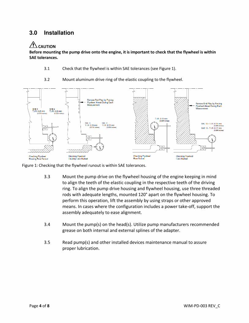
3.1 Check that the flywheel is within SAE tolerances (see Figure 1).
3.2 Mount aluminum drive ring of the elastic coupling to the flywheel.
Figure 1: Checking that the flywheel runout is within SAE tolerances.
3.3 Mount the pump drive on the flywheel housing of the engine keeping in mind
to align the teeth of the elastic coupling in the respective teeth of the driving
ring. To align the pump drive housing and flywheel housing, use three threaded
rods with adequate lengths, mounted 120° apart on the flywheel housing. To
perform this operation, lift the assembly by using straps or other approved
means. In cases where the configuration includes a power take-off, support the
assembly adequately to ease alignment.
3.4 Mount the pump(s) on the head(s). Utilize pump manufacturers recommended
grease on both internal and external splines of the adapter.
3.5 Read pump(s) and other installed devices maintenance manual to assure
proper lubrication.
Page 5 of 8 WIM-PD-003 REV_C
4.0 Maintenance
There are no specific maintenance items for the WPT Power Pump model WPD-03. No lubrication is
required for this unit.
5.0 Belt Replacement
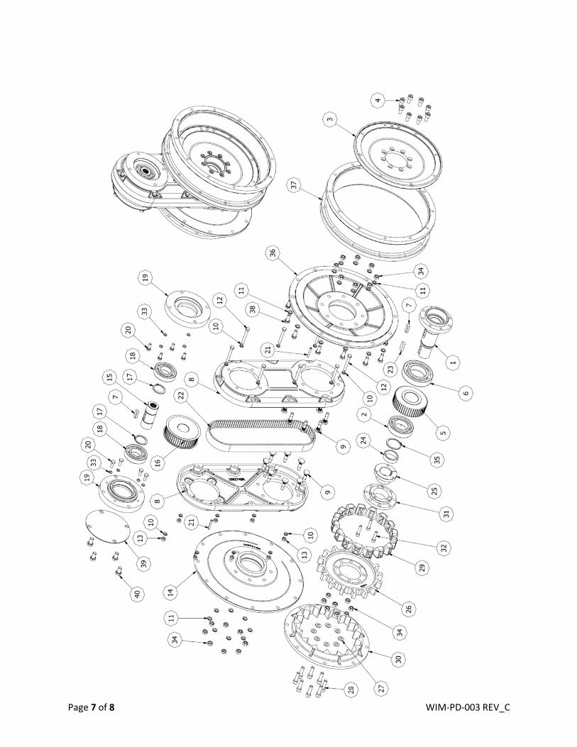
To replace the belt, follow steps below. See exploded view in section 6.
5.1 Remove pump drive from engine
5.2 Remove rubber block coupling assembly by removing bolts (32) and install into (31), use
them as jack bolts to separate from (25).
5.3 Remove flywheel (3) from output side.
5.4 Remove nuts (34) from output side to remove output flange and spacer (36) & (37).
5.5 Remove nuts (34) from engine input side to remove input flange (14).
5.6 Remove bolts (12) to separate belt housing halves (8).
5.7 Replace belt
5.8 Reassemble pump drive and install unit on engine. See Section 7 for bolt torque
specifications.
Page 6 of 8 WIM-PD-003 REV_C
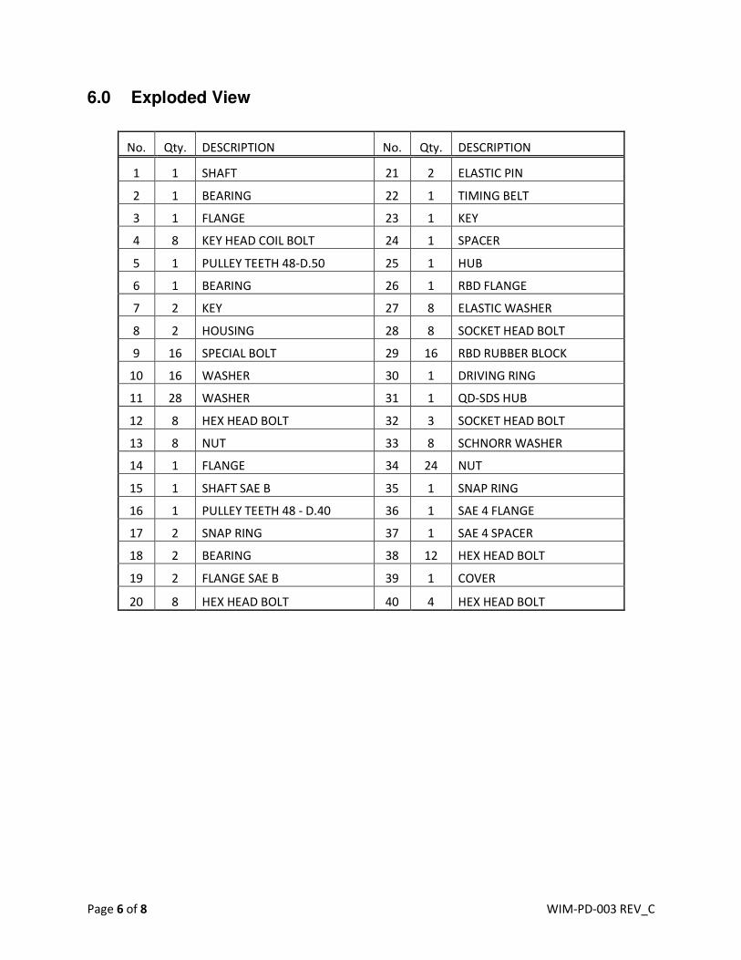
6.0 Exploded View
No. Qty. DESCRIPTION No. Qty. DESCRIPTION
1 1 SHAFT 21 2 ELASTIC PIN
2 1 BEARING 22 1 TIMING BELT
3 1 FLANGE 23 1 KEY
4 8 KEY HEAD COIL BOLT 24 1 SPACER
5 1 PULLEY TEETH 48-D.50 25 1 HUB
6 1 BEARING 26 1 RBD FLANGE
7 2 KEY 27 8 ELASTIC WASHER
8 2 HOUSING 28 8 SOCKET HEAD BOLT
9 16 SPECIAL BOLT 29 16 RBD RUBBER BLOCK
10 16 WASHER 30 1 DRIVING RING
11 28 WASHER 31 1 QD-SDS HUB
12 8 HEX HEAD BOLT 32 3 SOCKET HEAD BOLT
13 8 NUT 33 8 SCHNORR WASHER
14 1 FLANGE 34 24 NUT
15 1 SHAFT SAE B 35 1 SNAP RING
16 1 PULLEY TEETH 48 - D.40 36 1 SAE 4 FLANGE
17 2 SNAP RING 37 1 SAE 4 SPACER
18 2 BEARING 38 12 HEX HEAD BOLT
19 2 FLANGE SAE B 39 1 COVER
20 8 HEX HEAD BOLT 40 4 HEX HEAD BOLT
Page 7 of 8 WIM-PD-003 REV_C
Page 8 of 8 WIM-PD-003 REV_C
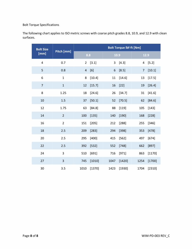
Bolt Torque Specifications
The following chart applies to ISO metric screws with coarse pitch grades 8.8, 10.9, and 12.9 with clean
surfaces.
Bolt Size
[mm] Pitch [mm]
Bolt Torque lbf-ft [Nm]
8.8 10.9 12.9
4 0.7 2 [3.1] 3 [4.3] 4 [5.2]
5 0.8 4 [6] 6 [8.5] 7 [10.1]
6 1 8 [10.4] 11 [14.6] 13 [17.5]
7 1 12 [15.7] 16 [22] 19 [26.4]
8 1.25 18 [24.6] 26 [34.7] 31 [41.6]
10 1.5 37 [50.1] 52 [70.5] 62 [84.6]
12 1.75 63 [84.8] 88 [119] 105 [143]
14 2 100 [135] 140 [190] 168 [228]
16 2 151 [205] 212 [288] 255 [346]
18 2.5 209 [283] 294 [398] 353 [478]
20 2.5 295 [400] 415 [562] 497 [674]
22 2.5 392 [532] 552 [748] 662 [897]
24 3 510 [691] 716 [971] 863 [1170]
27 3 745 [1010] 1047 [1420] 1254 [1700]
30 3.5 1010 [1370] 1423 [1930] 1704 [2310]