power supply system knx ps640-ip - id...
TRANSCRIPT

Power Supply System KNX PS640-IP with Ethernet Interface
Installation and Adjustment
Elsner Elektronik GmbH Steuerungs- und Automatisierungstechnik Herdweg 7 • D-75391 Gechingen • Germany Phone: +49 (0) 70 56/93 97-0 • Fax: +49 (0) 70 56/93 97-20 [email protected] • www.elsner-elektronik.de
2
Contents
Product description.......................................................................................................3 Application ........................................................................................................................................... 4 Technical data ...................................................................................................................................... 6
Installation and commissioning ....................................................................................7 Installation............................................................................................................................................ 7
Operation (Settings at the Device) ................................................................................9 Starting position .................................................................................................................................. 9 Line reset .............................................................................................................................................. 9 Data memory ..................................................................................................................................... 10 Operating data ................................................................................................................................... 11 Language............................................................................................................................................ 11
Setting of parameters (Software ETS).........................................................................13 General ............................................................................................................................................... 13 IP configuration.................................................................................................................................. 14 Routing (KNX -> IP)............................................................................................................................ 16 Routing (IP -> KNX)............................................................................................................................ 17
ETS Connection Manager ............................................................................................19
KNX PS640-IP from software version display 1.0, IP chip 1.1, ETS programme version 1.0 Version: 01/09/2009. Errors excepted. Subject to technical changes.

3
Product description The Power Supply System KNX PS640-IP combines the central functions of a KNX bus line: Power supply with throttle, IP router and IP interface: The power supply unit of the KNX PS640-IP delivers a 29 V bus voltage for the KNX system and 24 V DC supply voltage for 24 V devices. Special operating conditions such as short circuit, electrical surge, overcharge or excess temperature are recorded and may be read off on the display. The present power discharge is displayed as well. It is possible to reset the connected bus devices directly by means of the key pad. The IP router of the KNX PS640-IP allows for forwarding of telegrams between different lines via a rapid LAN (IP) backbone. The KNX PS640-IP therfore also takes on the function of a line coupler. In parallel, the KNX PS640-IP can be used as interface for accessing the bus via IP. Like this, the KNX system can be configuered and supervised from any PC in the LAN (Tunnelling). This device works according to the KNXnet/IP specification using the core, the device management, the tunnelling and the routing part. The router of KNX PS640-IP has a filter table and is able to buffer up to 150 telegrams.
Functions: • Delivers a 29 V KNX bus voltage (reduced), output current max. 640 mA, short-
circuit proof • Delivers 24 V DC (not reduced), output current max. 150 mA • Reset of a line directly on the device • Record of operating hours, overload, external overvoltage, internal overvoltage,
short circuit and excess temperature • Display of operating data bus voltage, bus current and temperature of the device • The display may be shown in German, English, Spanish or Dutch • Routing: Transfer of KNX data via LAN (rapid backbone) • Line coupler function via LAN • Tunnelling: Configuration and supervising of the KNX system from any PC in the
LAN
4
Application
Coupler function (KNXnet/IP Routing)
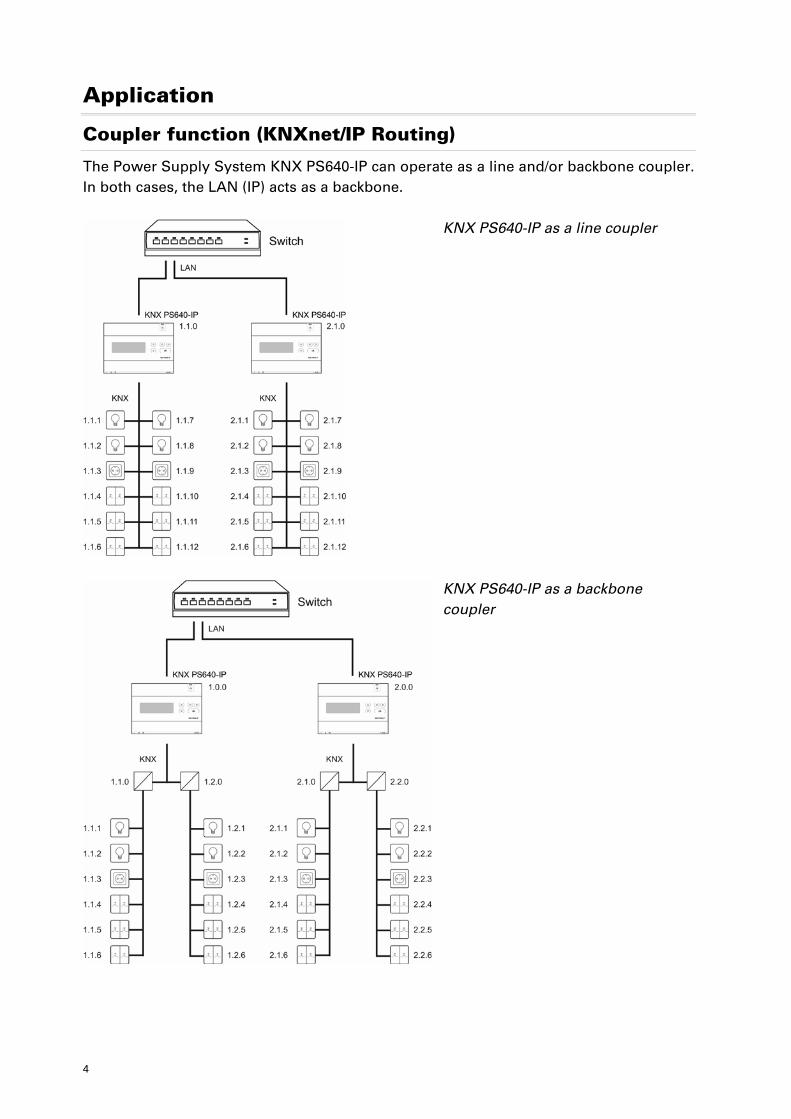
The Power Supply System KNX PS640-IP can operate as a line and/or backbone coupler. In both cases, the LAN (IP) acts as a backbone.
KNX PS640-IP as a line coupler
KNX PS640-IP as a backbone coupler
5
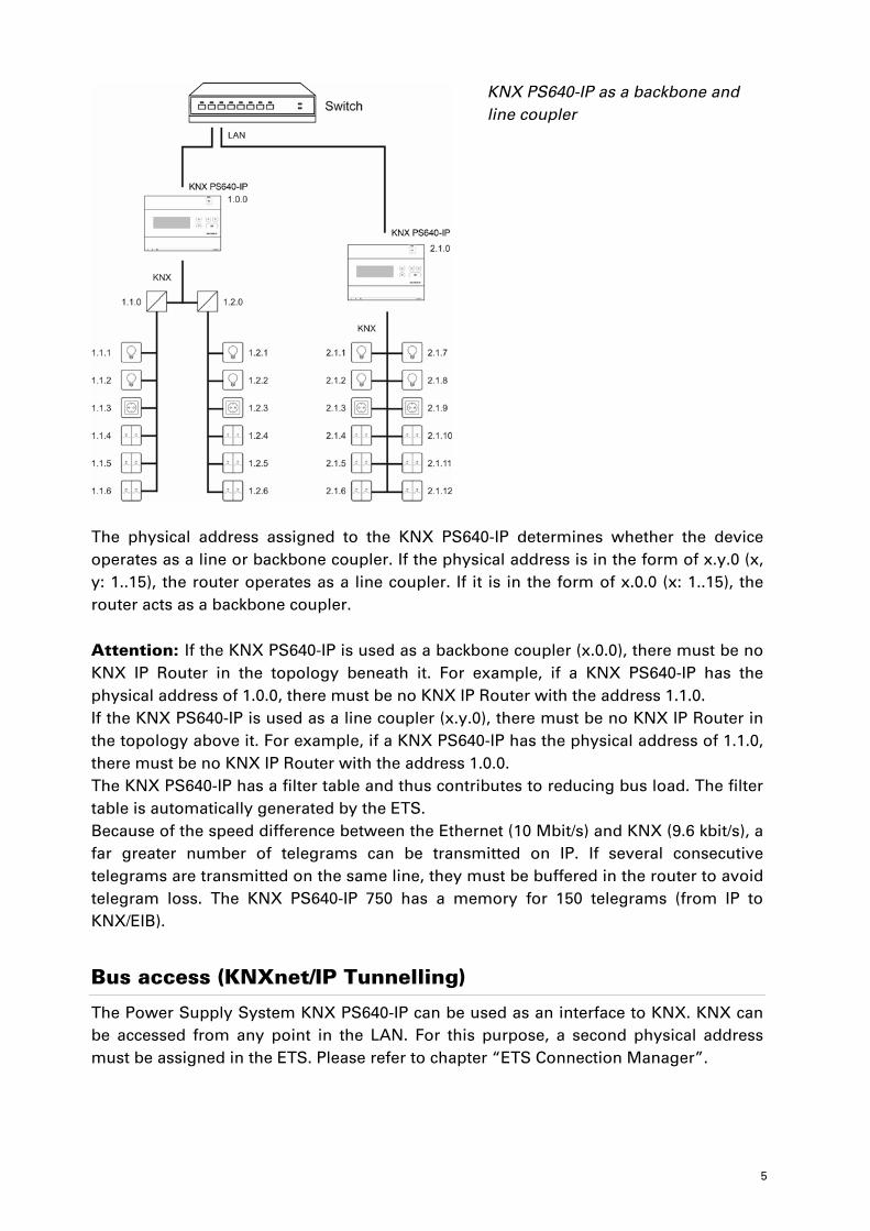
KNX PS640-IP as a backbone and line coupler
The physical address assigned to the KNX PS640-IP determines whether the device operates as a line or backbone coupler. If the physical address is in the form of x.y.0 (x, y: 1..15), the router operates as a line coupler. If it is in the form of x.0.0 (x: 1..15), the router acts as a backbone coupler. Attention: If the KNX PS640-IP is used as a backbone coupler (x.0.0), there must be no KNX IP Router in the topology beneath it. For example, if a KNX PS640-IP has the physical address of 1.0.0, there must be no KNX IP Router with the address 1.1.0. If the KNX PS640-IP is used as a line coupler (x.y.0), there must be no KNX IP Router in the topology above it. For example, if a KNX PS640-IP has the physical address of 1.1.0, there must be no KNX IP Router with the address 1.0.0. The KNX PS640-IP has a filter table and thus contributes to reducing bus load. The filter table is automatically generated by the ETS. Because of the speed difference between the Ethernet (10 Mbit/s) and KNX (9.6 kbit/s), a far greater number of telegrams can be transmitted on IP. If several consecutive telegrams are transmitted on the same line, they must be buffered in the router to avoid telegram loss. The KNX PS640-IP 750 has a memory for 150 telegrams (from IP to KNX/EIB).
Bus access (KNXnet/IP Tunnelling)
The Power Supply System KNX PS640-IP can be used as an interface to KNX. KNX can be accessed from any point in the LAN. For this purpose, a second physical address must be assigned in the ETS. Please refer to chapter “ETS Connection Manager”.
6
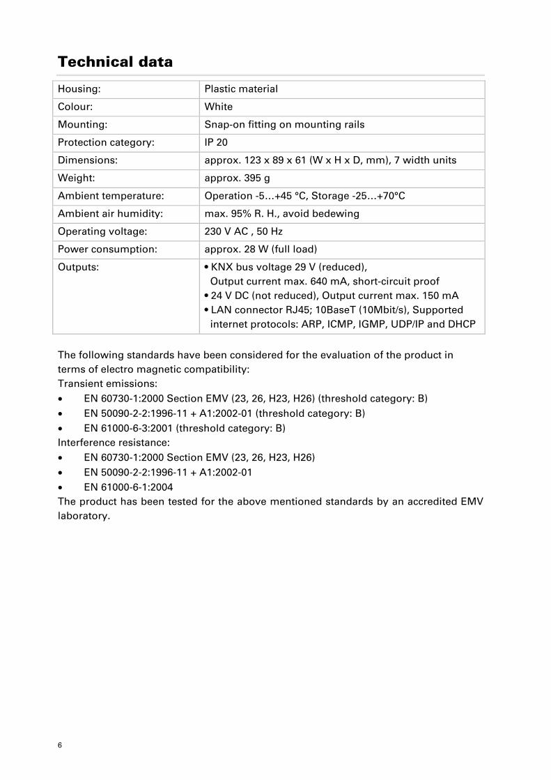
Technical data
Housing: Plastic material
Colour: White
Mounting: Snap-on fitting on mounting rails
Protection category: IP 20
Dimensions: approx. 123 x 89 x 61 (W x H x D, mm), 7 width units
Weight: approx. 395 g
Ambient temperature: Operation -5…+45 °C, Storage -25…+70°C
Ambient air humidity: max. 95% R. H., avoid bedewing
Operating voltage: 230 V AC , 50 Hz
Power consumption: approx. 28 W (full load)
Outputs: • KNX bus voltage 29 V (reduced), Output current max. 640 mA, short-circuit proof • 24 V DC (not reduced), Output current max. 150 mA • LAN connector RJ45; 10BaseT (10Mbit/s), Supported internet protocols: ARP, ICMP, IGMP, UDP/IP and DHCP
The following standards have been considered for the evaluation of the product in terms of electro magnetic compatibility: Transient emissions: • EN 60730-1:2000 Section EMV (23, 26, H23, H26) (threshold category: B) • EN 50090-2-2:1996-11 + A1:2002-01 (threshold category: B) • EN 61000-6-3:2001 (threshold category: B) Interference resistance: • EN 60730-1:2000 Section EMV (23, 26, H23, H26) • EN 50090-2-2:1996-11 + A1:2002-01 • EN 61000-6-1:2004 The product has been tested for the above mentioned standards by an accredited EMV laboratory.
7
Installation and commissioning
Attention! Mains voltage! The legal national regulations must be complied with.
Installation, inspection, commissioning and troubleshooting of the power supply system must only be carried out by a competent electrician. Disconnect all lines to be assembled, and take safety precautions against accidental switch-on. The power supply is exclusively intended for appropriate use. With each inappropriate change or non-observance of the instructions for use, any warranty or guarantee claim will be void. After unpacking the device, check immediately for any mechanical damages. In case of transport damage, this must immediately notified to the supplier.
If damaged, the power supply system must not be put into operation.
If an operation without risk may supposedly not be guaranteed, the plant must be put out of operation and be secured against accidental operation. The power supply system must only be operated as stationary system, i.e. only in a fitted state and after completion of all installation and start-up works, and only in the environment intended for this purpose. Elsner Elektronik does not assume any liability for changes in standards after publication of this instruction manual.
Installation
Observe the correct installation. Incorrect installation may destroy the power supply system or connected electronic devices.
8
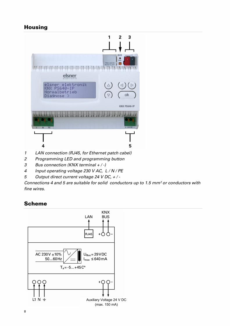
Housing
1 LAN connection (RJ45, for Ethernet patch cabel) 2 Programming LED and programming button 3 Bus connection (KNX terminal + / -) 4 Input operating voltage 230 V AC, L / N / PE 5 Output direct current voltage 24 V DC, + / - Connections 4 and 5 are suitable for solid conductors up to 1.5 mm² or conductors with fine wires.
Scheme
Auxiliary Voltage 24 V DC
(max. 150 mA)
9
Operation (Settings at the Device)
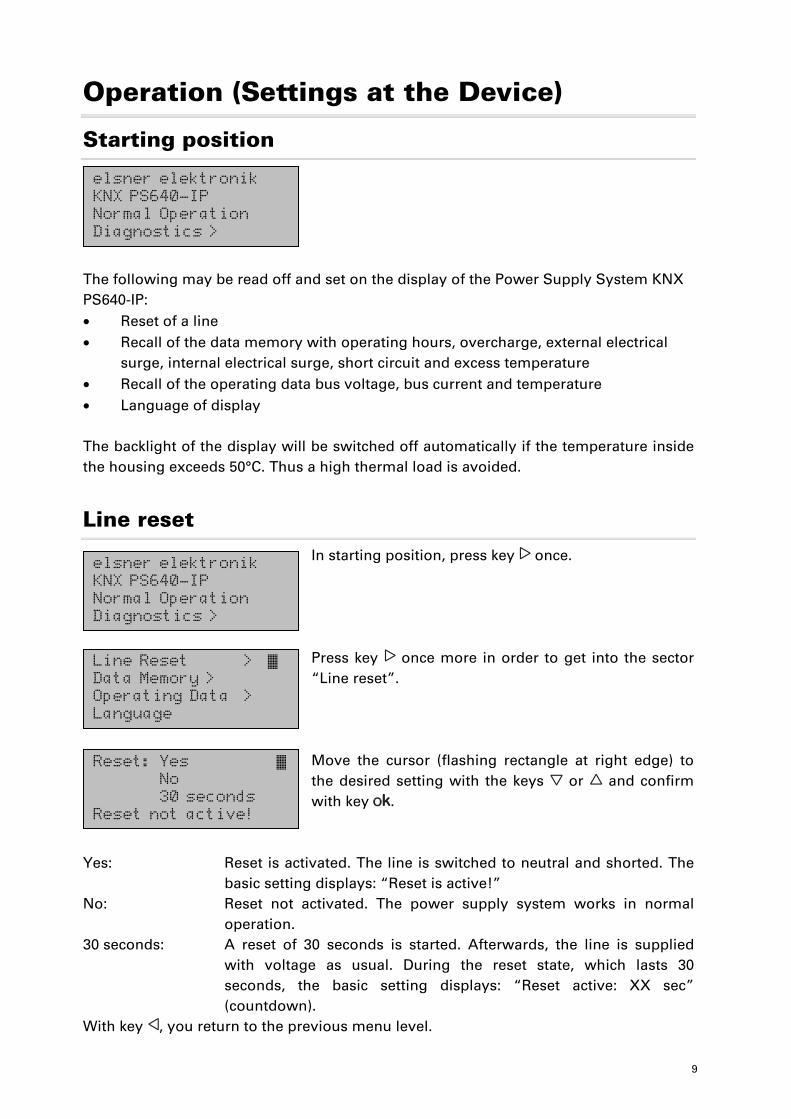
Starting position
The following may be read off and set on the display of the Power Supply System KNX PS640-IP: • Reset of a line • Recall of the data memory with operating hours, overcharge, external electrical
surge, internal electrical surge, short circuit and excess temperature • Recall of the operating data bus voltage, bus current and temperature • Language of display The backlight of the display will be switched off automatically if the temperature inside the housing exceeds 50°C. Thus a high thermal load is avoided.
Line reset
In starting position, press key once. Press key once more in order to get into the sector “Line reset”. Move the cursor (flashing rectangle at right edge) to the desired setting with the keys or and confirm with key .
Yes: Reset is activated. The line is switched to neutral and shorted. The
basic setting displays: “Reset is active!” No: Reset not activated. The power supply system works in normal
operation. 30 seconds: A reset of 30 seconds is started. Afterwards, the line is supplied
with voltage as usual. During the reset state, which lasts 30 seconds, the basic setting displays: “Reset active: XX sec” (countdown).
With key , you return to the previous menu level.
elsner elektronik KNX PS640-IP Normal Operation Diagnostics >
elsner elektronik KNX PS640-IP Normal Operation Diagnostics >
Line Reset > � Data Memory > Operating Data > Language
Reset: Yes � No 30 seconds Reset not active!
10
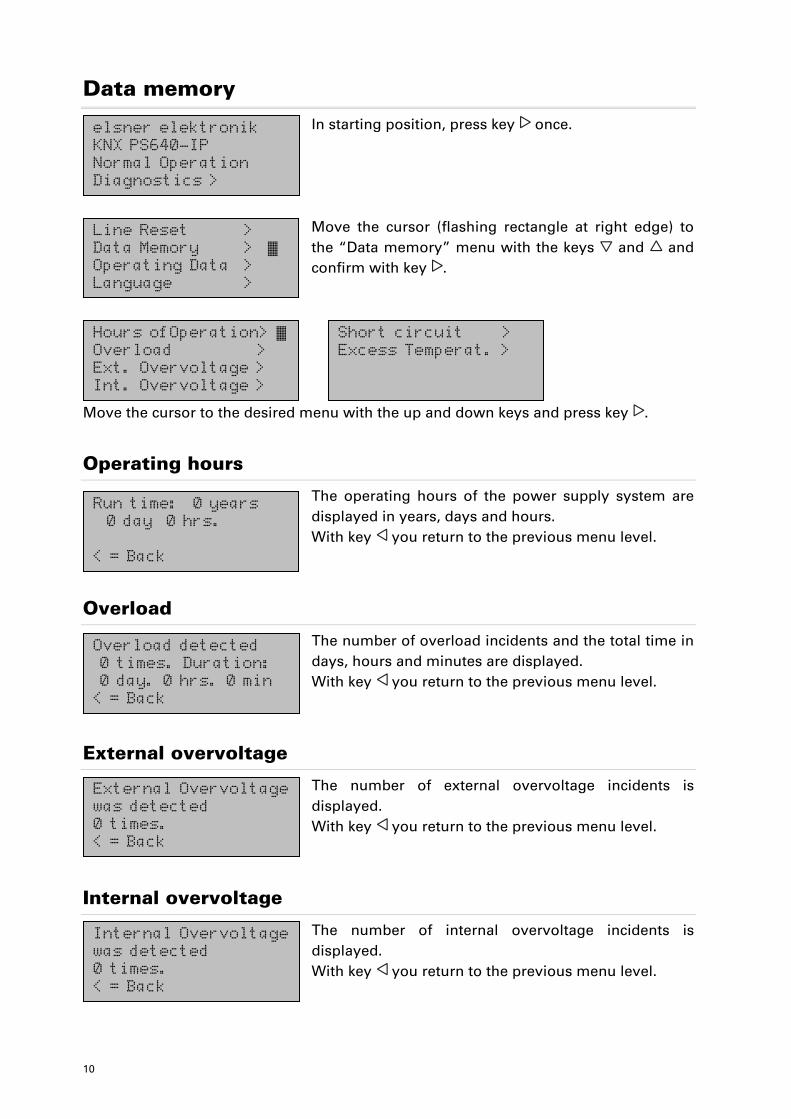
Data memory
In starting position, press key once.
Move the cursor (flashing rectangle at right edge) to the “Data memory” menu with the keys and and confirm with key .
Move the cursor to the desired menu with the up and down keys and press key .
Operating hours
The operating hours of the power supply system are displayed in years, days and hours. With key you return to the previous menu level.
Overload
The number of overload incidents and the total time in days, hours and minutes are displayed. With key you return to the previous menu level.
External overvoltage
The number of external overvoltage incidents is displayed. With key you return to the previous menu level.
Internal overvoltage
The number of internal overvoltage incidents is displayed. With key you return to the previous menu level.
Short circuit >Excess Temperat. >
Hours ofOperation> � Overload > Ext. Overvoltage > Int. Overvoltage >
elsner elektronik KNX PS640-IP Normal Operation Diagnostics >
Line Reset > Data Memory > � Operating Data > Language >
Run time: 0 years 0 day 0 hrs. < = Back
Overload detected 0 times. Duration: 0 day. 0 hrs. 0 min < = Back
External Overvoltage was detected 0 times. < = Back
Internal Overvoltage was detected 0 times. < = Back
11
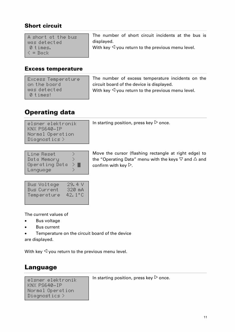
Short circuit
The number of short circuit incidents at the bus is displayed. With key you return to the previous menu level.
Excess temperature
The number of excess temperature incidents on the circuit board of the device is displayed. With key you return to the previous menu level.
Operating data
In starting position, press key once.
Move the cursor (flashing rectangle at right edge) to the “Operating Data” menu with the keys and and confirm with key .
The current values of • Bus voltage • Bus current • Temperature on the circuit board of the device are displayed. With key you return to the previous menu level.
Language
In starting position, press key once.
Bus Voltage 29.4 V Bus Current 320 mA Temperature 42.1°C
A short at the bus was detected 0 times. < = Back
Excess Temperature on the board was detected 0 times!
elsner elektronik KNX PS640-IP Normal Operation Diagnostics >
Line Reset > Data Memory > Operating Data > � Language >
elsner elektronik KNX PS640-IP Normal Operation Diagnostics >
12
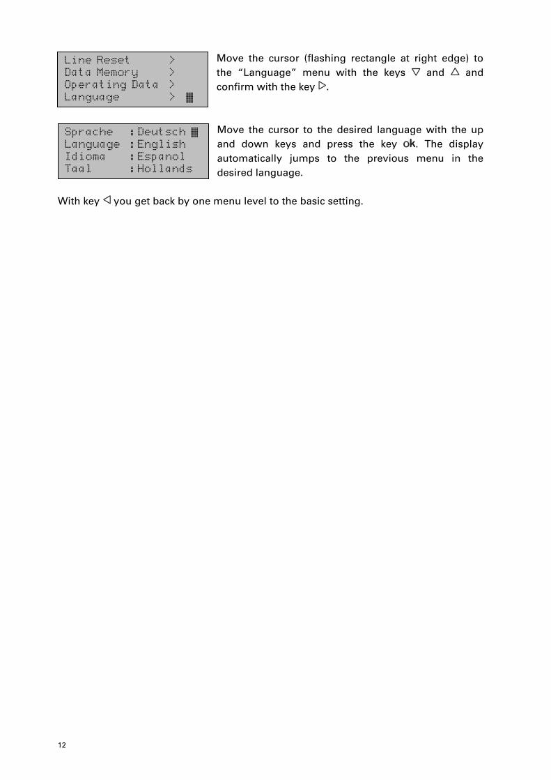
Move the cursor (flashing rectangle at right edge) to the “Language” menu with the keys and and confirm with the key .
Move the cursor to the desired language with the up and down keys and press the key . The display automatically jumps to the previous menu in the desired language.
With key you get back by one menu level to the basic setting.
Line Reset > Data Memory > Operating Data > Language > �
Sprache :Deutsch � Language :English Idioma :Espanol Taal :Hollands
13
Setting of parameters (Software ETS)
General
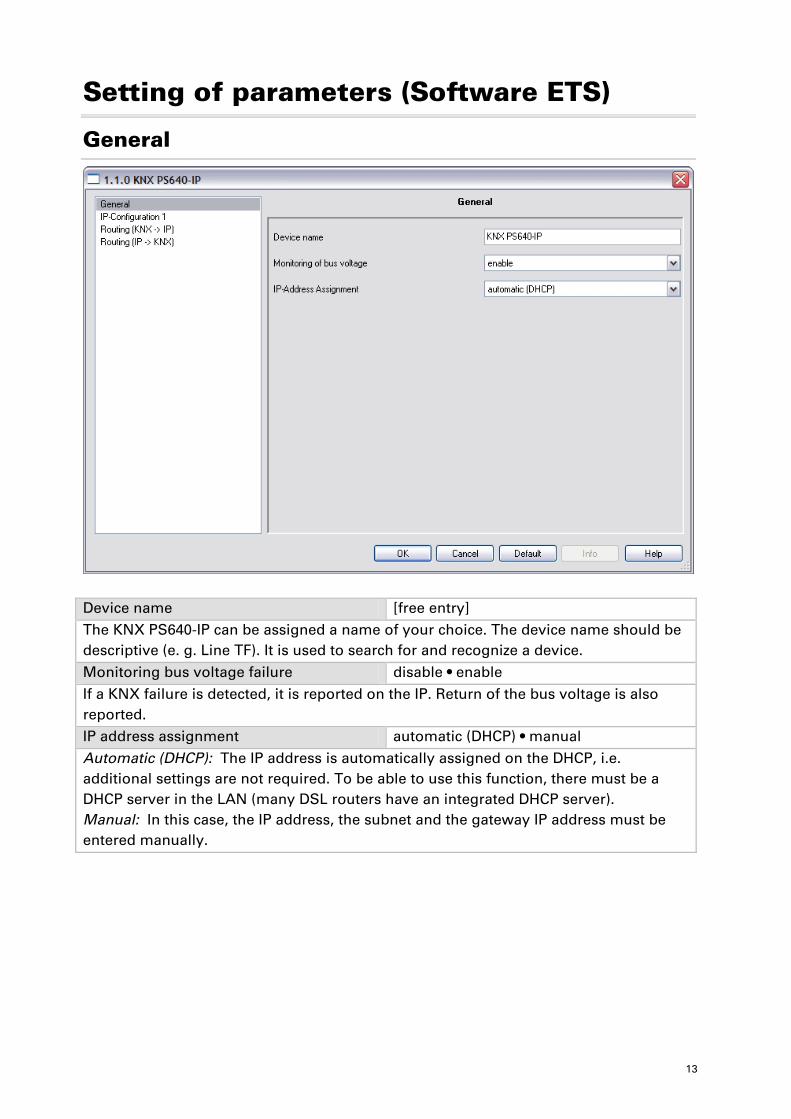
Device name [free entry] The KNX PS640-IP can be assigned a name of your choice. The device name should be descriptive (e. g. Line TF). It is used to search for and recognize a device.
Monitoring bus voltage failure disable • enable
If a KNX failure is detected, it is reported on the IP. Return of the bus voltage is also reported. IP address assignment automatic (DHCP) • manual
Automatic (DHCP): The IP address is automatically assigned on the DHCP, i.e. additional settings are not required. To be able to use this function, there must be a DHCP server in the LAN (many DSL routers have an integrated DHCP server). Manual: In this case, the IP address, the subnet and the gateway IP address must be entered manually.
14
IP configuration
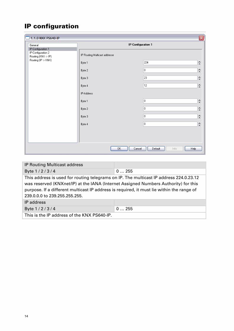
IP Routing Multicast address
Byte 1 / 2 / 3 / 4 0 … 255 This address is used for routing telegrams on IP. The multicast IP address 224.0.23.12 was reserved (KNXnet/IP) at the IANA (Internet Assigned Numbers Authority) for this purpose. If a different multicast IP address is required, it must lie within the range of 239.0.0.0 to 239.255.255.255.
IP address Byte 1 / 2 / 3 / 4 0 … 255
This is the IP address of the KNX PS640-IP.
15
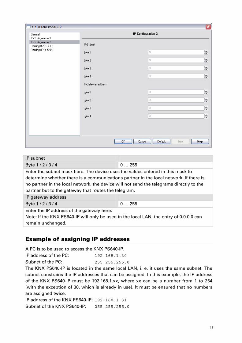
IP subnet
Byte 1 / 2 / 3 / 4 0 … 255 Enter the subnet mask here. The device uses the values entered in this mask to determine whether there is a communications partner in the local network. If there is no partner in the local network, the device will not send the telegrams directly to the partner but to the gateway that routes the telegram.
IP gateway address Byte 1 / 2 / 3 / 4 0 … 255
Enter the IP address of the gateway here. Note: If the KNX PS640-IP will only be used in the local LAN, the entry of 0.0.0.0 can remain unchanged.
Example of assigning IP addresses
A PC is to be used to access the KNX PS640-IP. IP address of the PC: 192.168.1.30 Subnet of the PC: 255.255.255.0 The KNX PS640-IP is located in the same local LAN, i. e. it uses the same subnet. The subnet constrains the IP addresses that can be assigned. In this example, the IP address of the KNX PS640-IP must be 192.168.1.xx, where xx can be a number from 1 to 254 (with the exception of 30, which is already in use). It must be ensured that no numbers are assigned twice. IP address of the KNX PS640-IP: 192.168.1.31 Subnet of the KNX PS640-IP: 255.255.255.0
16
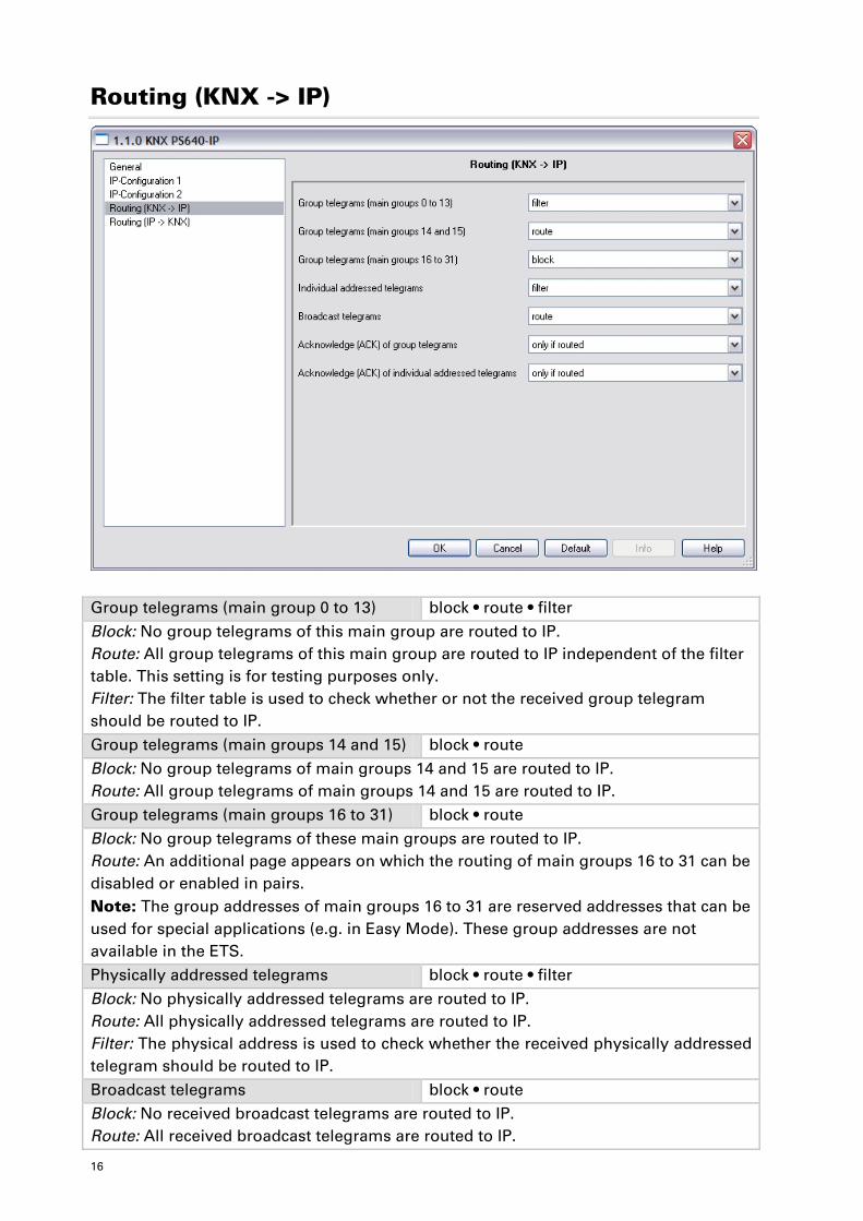
Routing (KNX -> IP)
Group telegrams (main group 0 to 13) block • route • filter
Block: No group telegrams of this main group are routed to IP. Route: All group telegrams of this main group are routed to IP independent of the filter table. This setting is for testing purposes only. Filter: The filter table is used to check whether or not the received group telegram should be routed to IP.
Group telegrams (main groups 14 and 15) block • route
Block: No group telegrams of main groups 14 and 15 are routed to IP. Route: All group telegrams of main groups 14 and 15 are routed to IP. Group telegrams (main groups 16 to 31) block • route
Block: No group telegrams of these main groups are routed to IP. Route: An additional page appears on which the routing of main groups 16 to 31 can be disabled or enabled in pairs. Note: The group addresses of main groups 16 to 31 are reserved addresses that can be used for special applications (e.g. in Easy Mode). These group addresses are not available in the ETS. Physically addressed telegrams block • route • filter
Block: No physically addressed telegrams are routed to IP. Route: All physically addressed telegrams are routed to IP. Filter: The physical address is used to check whether the received physically addressed telegram should be routed to IP.
Broadcast telegrams block • route Block: No received broadcast telegrams are routed to IP. Route: All received broadcast telegrams are routed to IP.
17
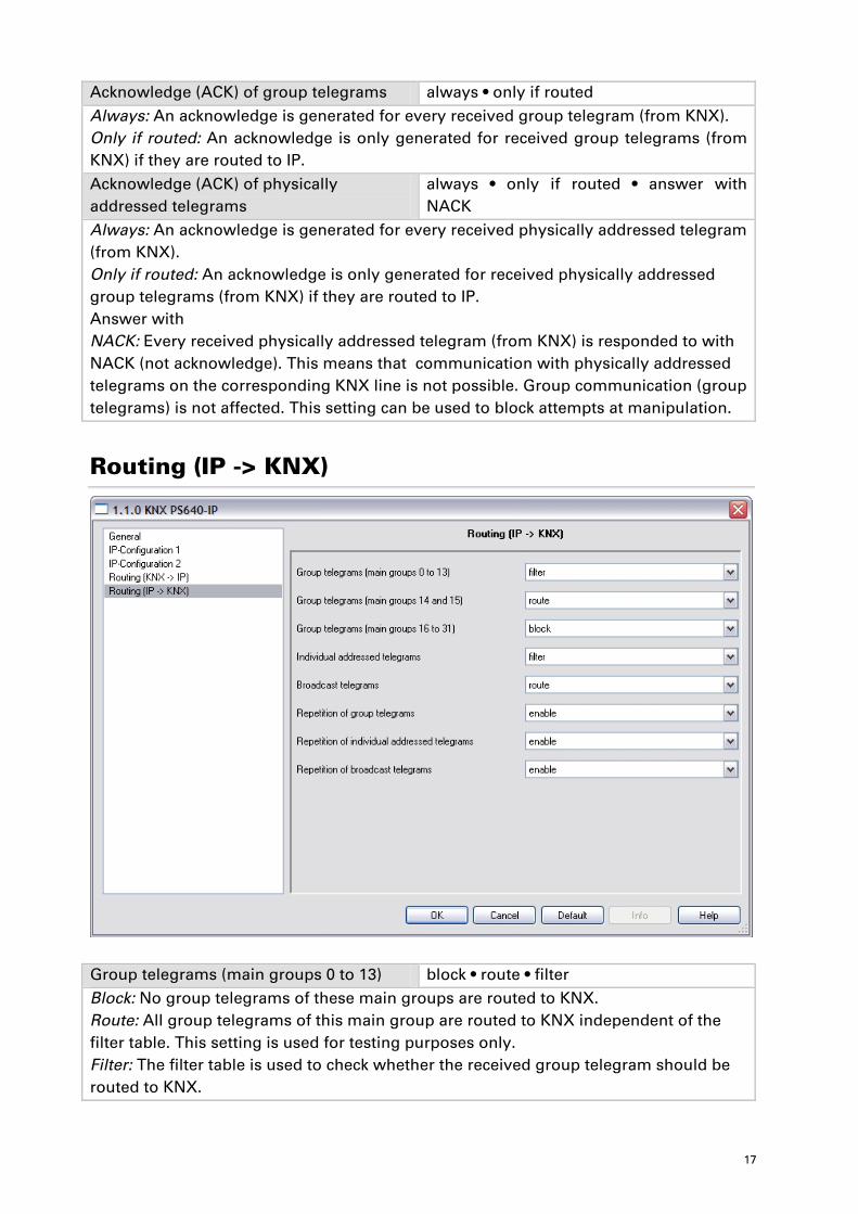
Acknowledge (ACK) of group telegrams always • only if routed
Always: An acknowledge is generated for every received group telegram (from KNX). Only if routed: An acknowledge is only generated for received group telegrams (from KNX) if they are routed to IP.
Acknowledge (ACK) of physically addressed telegrams
always • only if routed • answer with NACK
Always: An acknowledge is generated for every received physically addressed telegram (from KNX). Only if routed: An acknowledge is only generated for received physically addressed group telegrams (from KNX) if they are routed to IP. Answer with NACK: Every received physically addressed telegram (from KNX) is responded to with NACK (not acknowledge). This means that communication with physically addressed telegrams on the corresponding KNX line is not possible. Group communication (group telegrams) is not affected. This setting can be used to block attempts at manipulation.
Routing (IP -> KNX)
Group telegrams (main groups 0 to 13) block • route • filter Block: No group telegrams of these main groups are routed to KNX. Route: All group telegrams of this main group are routed to KNX independent of the filter table. This setting is used for testing purposes only. Filter: The filter table is used to check whether the received group telegram should be routed to KNX.
18
Group telegrams (main groups 14 and 15) block • route
Block: No group telegrams of main groups 14 and 15 are routed to KNX. Route: All group telegrams of the main groups 14 and 15 are routed to KNX.
Group telegrams (main groups 16 to 31) block • route
Block: No group telegrams of these main groups are routed to KNX. Route: An additional page appears on which the routing of main groups 16 to 31 can be disabled or enabled in pairs. Physically addressed telegrams block • route • filter
Block: No physically addressed telegrams are routed to KNX. Route: All physically addressed telegrams are routed to KNX. Filter: The physical address is used to check whether the received physically addressed telegram should be routed to KNX. Broadcast telegrams block • route
Block: No received broadcast telegrams are routed to KNX. Route: All received broadcast telegrams are routed to KNX. Resending of group telegrams block • route
Disable: The received group telegram is not resent to KNX in case of a fault. Enable: The received group telegram is resent up to three times in case of a fault. Resending of physically addressed telegrams
block • route
Disable: The received physically addressed telegram is not resent to KNX in case of a fault. Enable: The received physically addressed telegram is resent up to three times in case of a fault. Resending of broadcast telegrams block • route
Disable: The received broadcast telegram is not resent to KNX in case of a fault. Enable: The received broadcast telegram is resent up to three times in case of a fault.
19
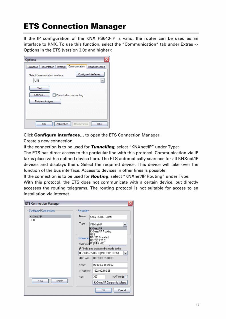
ETS Connection Manager If the IP configuration of the KNX PS640-IP is valid, the router can be used as an interface to KNX. To use this function, select the “Communication” tab under Extras -> Options in the ETS (version 3.0c and higher):
Click Configure interfaces… to open the ETS Connection Manager. Create a new connection. If the connection is to be used for Tunnelling, select “KNXnet/IP” under Type: The ETS has direct access to the particular line with this protocol. Communication via IP takes place with a defined device here. The ETS automatically searches for all KNXnet/IP devices and displays them. Select the required device. This device will take over the function of the bus interface. Access to devices in other lines is possible. If the connection is to be used for Routing, select “KNXnet/IP Routing” under Type: With this protocol, the ETS does not communicate with a certain device, but directly accesses the routing telegrams. The routing protocol is not suitable for access to an installation via internet.
20
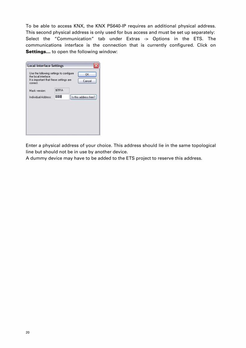
To be able to access KNX, the KNX PS640-IP requires an additional physical address. This second physical address is only used for bus access and must be set up separately: Select the “Communication” tab under Extras -> Options in the ETS. The communications interface is the connection that is currently configured. Click on Settings… to open the following window:
Enter a physical address of your choice. This address should lie in the same topological line but should not be in use by another device. A dummy device may have to be added to the ETS project to reserve this address.