powerflex 755 integarated safety - safe torque off option ... · throughout this manual, the...
TRANSCRIPT

PowerFlex 755/755T Integrated Safety - Safe Torque Off Option ModuleCatalog Number 20-750-S3
User ManualOriginal Instructions

Important User Information
Read this document and the documents listed in the additional resources section about installation, configuration, and operation of this equipment before you install, configure, operate, or maintain this product. Users are required to familiarize themselves with installation and wiring instructions in addition to requirements of all applicable codes, laws, and standards.
Activities including installation, adjustments, putting into service, use, assembly, disassembly, and maintenance are required to be carried out by suitably trained personnel in accordance with applicable code of practice.
If this equipment is used in a manner not specified by the manufacturer, the protection provided by the equipment may be impaired.
In no event will Rockwell Automation, Inc. be responsible or liable for indirect or consequential damages resulting from the use or application of this equipment.
The examples and diagrams in this manual are included solely for illustrative purposes. Because of the many variables and requirements associated with any particular installation, Rockwell Automation, Inc. cannot assume responsibility or liability for actual use based on the examples and diagrams.
No patent liability is assumed by Rockwell Automation, Inc. with respect to use of information, circuits, equipment, or software described in this manual.
Reproduction of the contents of this manual, in whole or in part, without written permission of Rockwell Automation, Inc., is prohibited.
Throughout this manual, when necessary, we use notes to make you aware of safety considerations.
Labels may also be on or inside the equipment to provide specific precautions.
WARNING: Identifies information about practices or circumstances that can cause an explosion in a hazardous environment, which may lead to personal injury or death, property damage, or economic loss.
ATTENTION: Identifies information about practices or circumstances that can lead to personal injury or death, property damage, or economic loss. Attentions help you identify a hazard, avoid a hazard, and recognize the consequence.
IMPORTANT Identifies information that is critical for successful application and understanding of the product.
SHOCK HAZARD: Labels may be on or inside the equipment, for example, a drive or motor, to alert people that dangerous voltage may be present.
BURN HAZARD: Labels may be on or inside the equipment, for example, a drive or motor, to alert people that surfaces may reach dangerous temperatures.
ARC FLASH HAZARD: Labels may be on or inside the equipment, for example, a motor control center, to alert people to potential Arc Flash. Arc Flash will cause severe injury or death. Wear proper Personal Protective Equipment (PPE). Follow ALL Regulatory requirements for safe work practices and for Personal Protective Equipment (PPE).

Table of Contents
Preface Summary of Changes . . . . . . . . . . . . . . . . . . . . . . . . . . . . . . . . . . . . . . . . . . . 7Conventions . . . . . . . . . . . . . . . . . . . . . . . . . . . . . . . . . . . . . . . . . . . . . . . . . . . 7Terminology . . . . . . . . . . . . . . . . . . . . . . . . . . . . . . . . . . . . . . . . . . . . . . . . . . . 8Product Firmware and Release Notes . . . . . . . . . . . . . . . . . . . . . . . . . . . . 9Additional Resources . . . . . . . . . . . . . . . . . . . . . . . . . . . . . . . . . . . . . . . . . . 10
Chapter 1Safety Concept What Is the Integrated Safety - Safe Torque Off Option Module? . 11
Compatible Drives . . . . . . . . . . . . . . . . . . . . . . . . . . . . . . . . . . . . . . . . . . . . 12Compatible Safety Controllers . . . . . . . . . . . . . . . . . . . . . . . . . . . . . . . . . 13
Network Mode. . . . . . . . . . . . . . . . . . . . . . . . . . . . . . . . . . . . . . . . . . . . 13Hardwired Mode . . . . . . . . . . . . . . . . . . . . . . . . . . . . . . . . . . . . . . . . . . 14
Safety Application Requirements . . . . . . . . . . . . . . . . . . . . . . . . . . . . . . . 14Safety Certification. . . . . . . . . . . . . . . . . . . . . . . . . . . . . . . . . . . . . . . . . . . . 14
Important Safety Considerations . . . . . . . . . . . . . . . . . . . . . . . . . . . 14Stop Category Definitions. . . . . . . . . . . . . . . . . . . . . . . . . . . . . . . . . . 15Performance Level and Safety Integrity Level (SIL) CL3 . . . . . . 16
Functional Proof Tests . . . . . . . . . . . . . . . . . . . . . . . . . . . . . . . . . . . . . . . . 16PFD and PFH Definitions . . . . . . . . . . . . . . . . . . . . . . . . . . . . . . . . . . . . . 16PFD and PFH Data . . . . . . . . . . . . . . . . . . . . . . . . . . . . . . . . . . . . . . . . . . . 17Safety Reaction Time . . . . . . . . . . . . . . . . . . . . . . . . . . . . . . . . . . . . . . . . . . 17
Reaction Time in Network STO Mode. . . . . . . . . . . . . . . . . . . . . . 17Reaction Time in Hardwired STO Mode. . . . . . . . . . . . . . . . . . . . 18
Considerations for Safety Ratings. . . . . . . . . . . . . . . . . . . . . . . . . . . . . . . 18Contact Information If Safety Option Failure Occurs . . . . . . . . . . . . 18
Chapter 2Installation Remove Power from the Drive System . . . . . . . . . . . . . . . . . . . . . . . . . . 20
Access the Control Pod . . . . . . . . . . . . . . . . . . . . . . . . . . . . . . . . . . . . . . . . 20Set the Safety Jumper . . . . . . . . . . . . . . . . . . . . . . . . . . . . . . . . . . . . . . . . . . 21Install the Safety Option Module . . . . . . . . . . . . . . . . . . . . . . . . . . . . . . . 22
Chapter 3Configuration Description of Operation . . . . . . . . . . . . . . . . . . . . . . . . . . . . . . . . . . . . . . 25
Out-of-Box State . . . . . . . . . . . . . . . . . . . . . . . . . . . . . . . . . . . . . . . . . . . . . . 26Recognize Out-of-Box State . . . . . . . . . . . . . . . . . . . . . . . . . . . . . . . . 26Restore the Drive to Out-of-Box State. . . . . . . . . . . . . . . . . . . . . . . 26
Chapter 4Standard I/O – Network STO Programmingand Operation
Description of Integrated Operation . . . . . . . . . . . . . . . . . . . . . . . . . . . . 29Safe Torque Off Assembly Tags . . . . . . . . . . . . . . . . . . . . . . . . . . . . . . . . 30Configure Safe Torque Off in the Logix Designer Application . . . . 31
Rockwell Automation Publication 750-UM004C-EN-P - August 2019 3

Table of Contents
Add a PowerFlex 755/755T Drive Product to the ControllerProject. . . . . . . . . . . . . . . . . . . . . . . . . . . . . . . . . . . . . . . . . . . . . . . . . . . . 33Add an Option Module to a PowerFlex 755/755T DriveProduct in I/O Mode . . . . . . . . . . . . . . . . . . . . . . . . . . . . . . . . . . . . . . 34Generate the Safety Network Number (SNN) . . . . . . . . . . . . . . . 35Configure Safety Connections . . . . . . . . . . . . . . . . . . . . . . . . . . . . . . 36Using a 20-750-ENETR Dual-port EtherNet/IP OptionModule with a 20-750-S3 Option Module . . . . . . . . . . . . . . . . . . . 40Safety Configuration Signature and Ownership . . . . . . . . . . . . . . 42Reset Ownership . . . . . . . . . . . . . . . . . . . . . . . . . . . . . . . . . . . . . . . . . . 42
Safe Torque Off – Stop Category 0 Example Program . . . . . . . . . . . . 43Safe Torque Off – Stop Category 1 Example Program . . . . . . . . . . . . 44
Falling Edge Reset . . . . . . . . . . . . . . . . . . . . . . . . . . . . . . . . . . . . . . . . . 45Safety Tags in Standard Routines . . . . . . . . . . . . . . . . . . . . . . . . . . . 45Standard Tags in Safety Routines (tag mapping). . . . . . . . . . . . . . 45
Safe Torque Off Fault Reset . . . . . . . . . . . . . . . . . . . . . . . . . . . . . . . . . . . . 46Understand Integrated Safety Drive Replacement . . . . . . . . . . . . . . . . 47Replace an Integrated Safety Drive in a GuardLogix System . . . . . . . 47
Chapter 5Integrated Motion – Network STO Programming and Operation
Requirements . . . . . . . . . . . . . . . . . . . . . . . . . . . . . . . . . . . . . . . . . . . . . . . . . 51Description of Operation . . . . . . . . . . . . . . . . . . . . . . . . . . . . . . . . . . . . . . 51
Safe Torque Off Assembly Tags. . . . . . . . . . . . . . . . . . . . . . . . . . . . . 52Configure Safe Torque Off in the Logix Designer Application . . . . 54
Add a PowerFlex 755 Drive to the Controller Project. . . . . . . . . 55Configure an Option Card on a PowerFlex 755 Drive inIntegrated Motion on EtherNet/IP Network Applications. . . . 56Generate the Safety Network Number (SNN) . . . . . . . . . . . . . . . 57Configure Safety Connections . . . . . . . . . . . . . . . . . . . . . . . . . . . . . . 58Safety Configuration Signature and Ownership . . . . . . . . . . . . . . 60Reset Ownership . . . . . . . . . . . . . . . . . . . . . . . . . . . . . . . . . . . . . . . . . . 60
Safe Torque Off – Stop Category 0 Example Program . . . . . . . . . . . . 61Safe Torque Off – Stop Category 1 Example Program . . . . . . . . . . . . 62
Falling Edge Reset . . . . . . . . . . . . . . . . . . . . . . . . . . . . . . . . . . . . . . . . . 62Safety Tags in Standard Routines . . . . . . . . . . . . . . . . . . . . . . . . . . . 63Standard Tags in Safety Routines (tag mapping). . . . . . . . . . . . . . 63STO Fault Reset. . . . . . . . . . . . . . . . . . . . . . . . . . . . . . . . . . . . . . . . . . . 64Troubleshoot the Safe Torque Off Function . . . . . . . . . . . . . . . . . 65Understand Integrated Safety Drive Replacement . . . . . . . . . . . . 65Replace an Integrated Safety Drive in a GuardLogix System . . . 66Motion Direct Commands in Motion Control Systems. . . . . . . 67
4 Rockwell Automation Publication 750-UM004C-EN-P - August 2019

Table of Contents
Chapter 6Hardwired STO Wiring and Operation
Wiring . . . . . . . . . . . . . . . . . . . . . . . . . . . . . . . . . . . . . . . . . . . . . . . . . . . . . . . 75Cabling . . . . . . . . . . . . . . . . . . . . . . . . . . . . . . . . . . . . . . . . . . . . . . . . . . . 76Power Supply Requirements . . . . . . . . . . . . . . . . . . . . . . . . . . . . . . . . 76
Description of Hardwired Operation . . . . . . . . . . . . . . . . . . . . . . . . . . . 77Selection of Hardwired Operation . . . . . . . . . . . . . . . . . . . . . . . . . . . . . . 77Configure the Drive with Hardwired Safety Connections . . . . . . . . 77Timing Diagrams . . . . . . . . . . . . . . . . . . . . . . . . . . . . . . . . . . . . . . . . . . . . . 78
Chapter 7Monitoring and Troubleshooting Monitor STO Status . . . . . . . . . . . . . . . . . . . . . . . . . . . . . . . . . . . . . . . . . . 81
Module Status Indicator (DS1) . . . . . . . . . . . . . . . . . . . . . . . . . . . . . 81Network Status Indicator (DS2) . . . . . . . . . . . . . . . . . . . . . . . . . . . . 82Motion Output Status Indicator (DS3) . . . . . . . . . . . . . . . . . . . . . 82
Monitor STO With a HIM or Software. . . . . . . . . . . . . . . . . . . . . . . . . 83Fault Messages on HIM, Drive Module, and Connected Components Workbench Software . . . . . . . . . . . . . . . . . . . . . . . . . 83Safety Supervisor State . . . . . . . . . . . . . . . . . . . . . . . . . . . . . . . . . . . . . 86Safe Torque Off Faults . . . . . . . . . . . . . . . . . . . . . . . . . . . . . . . . . . . . . 86
Appendix ASpecifications, Certifications, and CE Conformity
Integrated Safety - Safe Torque Off Option Module Specifications 87Environmental Specifications . . . . . . . . . . . . . . . . . . . . . . . . . . . . . . . . . . 88Certifications . . . . . . . . . . . . . . . . . . . . . . . . . . . . . . . . . . . . . . . . . . . . . . . . . 89
Waste Electrical and Electronic Equipment (WEEE) . . . . . . . . . 89
Appendix BSTO Option Module Replacement Considerations
Installation Considerations . . . . . . . . . . . . . . . . . . . . . . . . . . . . . . . . . . . . 91Option Module Slots . . . . . . . . . . . . . . . . . . . . . . . . . . . . . . . . . . . . . . 91
Wiring . . . . . . . . . . . . . . . . . . . . . . . . . . . . . . . . . . . . . . . . . . . . . . . . . . . . . . . 92Safe Torque Off Option Module. . . . . . . . . . . . . . . . . . . . . . . . . . . . 92Integrated Safety - Safe Torque Off Option Module . . . . . . . . . . 92
Appendix CParameter Data Parameters and Settings in a Linear List . . . . . . . . . . . . . . . . . . . . . . . . . 93
Device Config Parameters . . . . . . . . . . . . . . . . . . . . . . . . . . . . . . . . . . 93Host Config Parameters. . . . . . . . . . . . . . . . . . . . . . . . . . . . . . . . . . . . 95
Index . . . . . . . . . . . . . . . . . . . . . . . . . . . . . . . . . . . . . . . . . . . . . . . . . . . . . . . . . . . . . . . . 97
Rockwell Automation Publication 750-UM004C-EN-P - August 2019 5

Table of Contents
Notes:
6 Rockwell Automation Publication 750-UM004C-EN-P - August 2019

Preface
This user manual explains how to use PowerFlex® 755 drives and PowerFlex 755T drive products in safety integrity level (SIL) 3, Performance Level (PL) PLe, Category (CAT) 3 applications.
This user manual is intended for people that design, install, configure, or troubleshoot safety applications that use the Integrated Safety - Safe Torque Off option module (catalog number 20-750-S3).
This user manual describes the safety requirements, including probability of a dangerous failure on demand (PFD) and average frequency of a dangerous failure (PFH) values and application verification information (see PFD and PFH Data on page 17).
Summary of Changes This manual contains new and updated information as indicated in the following table.
Conventions This manual lists parameter names followed by the number in brackets. For example, STO Fault Type [P7]. Both Host Config and Device Config parameters exist for this option module and the parameter numbers overlap. For example, there is a Device Config Identity Status [P1], and a Host Config Guard Status [P1].
Topic Page
Summary of Changes 7
Conventions 7
Terminology 8
Product Firmware and Release Notes 9
Additional Resources 10
IMPORTANT You must have a basic understanding of electrical circuitry and familiarity with PowerFlex 755 drives and PowerFlex 755T drive products. You must also be trained and experienced in the creation, operation, and maintenance of safety systems.
Topic Page
Added additional frame sizes to Table 3 and Table 4 17
Updated screen captures to reflect latest add-on profile (AOP) throughout manual
Added additional information about using the 20-750-ENETR Dual-port EtherNet/IP option module with the Integrated Safety - Safe Torque Off option module
33, 40, and 41
Rockwell Automation Publication 750-UM004C-EN-P - August 2019 7

Preface
Throughout this manual, the PowerFlex 755 Integrated Safety - Safe Torque Off option module is also referred to as the Integrated Safety - Safe Torque Off option module. Throughout this manual, the PowerFlex 755TL low harmonic drives, PowerFlex 755TR regenerative drives, PowerFlex 755TM drive systems are also referred to as PowerFlex 755T drive products. The PowerFlex 755 drive is used for the examples in this manual.
Terminology Table 1 defines the abbreviations that are used in this manual.
Table 1 - Abbreviations and Definitions
Abbreviation Full Term Definition
1oo2 One out of Two Refers to the behavioral design of a dual-channel safety system.
CAT CategoryClassification of the safety-related parts of a control system in respect of their resistance to faults and their subsequent behavior in the fault condition, and which is achieved by the structural arrangement of the parts, fault detection, and/or by their reliability (source ISO 13849).
CL Claim Limit The maximum SIL rating that can be claimed for a safety-related electrical control system subsystem in relation to architectural constraints and systematic safety integrity (source IEC 62061).
DeviceID Device ID A unique identifier, comprised of the module number and SNN, to make sure that duplicate module numbers do not compromise communication between the correct safety devices.
EN European Norm The official European Standard.
ESD Emergency Shutdown Systems A system, usually independent of the main control system, which is designed to safely shut down an operating system.
ESPE Electro-sensitive Protective Equipment
An assembly of devices and/or components working together for protective tripping or presence-sensing purposes and includes as a minimum:• A sensing device.• Controlling/monitoring devices.• Output signal-switching devices (OSSD).
HFT Hardware Fault Tolerance The HFT equals n, where n+1 faults could cause the loss of the safety function. An HFT of one means that two faults are required before safety is lost.
HIM Human Interface Module A module that is used to configure a device.
IEC International Electrotechnical Commission The International Electrotechnical Commission (IEC) is the organization that prepares and publishes international standards for all electrical, electronic, and related technologies.
IGBT Insulated Gate Bipolar Transistors Typical power switch that is used to control main current.
ISO International Organization for Standardization The International Organization for Standardization is an international standard-setting body that is composed of representatives from various national standards organizations.
NC Normally Closed A set of contacts on a relay or switch that are closed when the relay is de-energized or the switch is de-activated.
NO Normally Open A set of contacts on a relay or switch that are open when the relay is de-energized or the switch is de-activated.
OSSD Output Signal Switching DeviceThe component of the electro-sensitive protective equipment (ESPE) connected to the control system of a machine. When the sensing device is actuated during normal operation, the device responds by going to the OFF-state.
PELV Protective Extra Low Voltage An electrical system where the voltage cannot exceed ELV under normal conditions, and under single-fault conditions, except earth faults in other circuits.
PFD Probability of a Dangerous Failure on Demand The average probability of a system to fail to perform its design function on demand.
PFH Average Frequency of a Dangerous Failure per hour The average frequency of a system to have a dangerous failure occur per hour.
PL Performance Level EN ISO 13849-1 safety rating
PM Permanent Magnet In permanent magnet (PM) motors, magnets mounted on or embedded in the rotor, couple with the current-induced internal magnetic fields of the motor generated by electrical input to the stator.
8 Rockwell Automation Publication 750-UM004C-EN-P - August 2019

Preface
Product Firmware and Release Notes
Product firmware and release notes are available online within the Product Compatibility and Download Center.
1. From the Search bar on http://www.ab.com, choose Compatibility and Downloads.
2. Search for your product.
3. On the search results page, find the firmware and release notes for your product. If no firmware/release notes are available, the module is still shipping with its original firmware release.
See the Product Compatibility and Download Center Quick Start Guide, publication PCDC-QS001, for instructions on how to find and download firmware and release notes.
SELV Safety Extra Low Voltage Circuit A secondary circuit that is designed and protected so that, under normal and single fault conditions, its voltages do not exceed a safe value.
SIL Safety Integrity Level A measure of a products ability to lower the risk that a dangerous failure could occur.
SSN Safety Network Number A unique number that identifies a section of a safety network.
STO Safe Torque OffThe Safe Torque Off (STO) function is used to help prevent unexpected motor rotation during an emergency while the drive remains connected to the power supply. When STO is activated, the torque power cannot reach the drive, which stops and helps prevent any motor shaft rotation.
Table 1 - Abbreviations and Definitions (continued)
Abbreviation Full Term Definition
Rockwell Automation Publication 750-UM004C-EN-P - August 2019 9

Preface
Additional Resources These documents contain additional information concerning related Rockwell Automation products.
You can view or download publications athttp://www.rockwellautomation.com/global/literature-library/overview.page. To order paper copies of technical documentation, contact your local Allen-Bradley distributor or Rockwell Automation sales representative.
Resource Description
PowerFlex 750-Series Products with TotalFORCE® Control Installation Instructions, publication 750-IN100
Provides the basic steps to install PowerFlex 755TL low harmonic drives, PowerFlex 755TR regenerative drives, and PowerFlex 755TM drive systems.
PowerFlex 755TM IP00 Open Type Kits Installation Instructions, publication 750-IN101
Provides instructions to install IP00 Open Type kits in user-supplied enclosures.
PowerFlex Drives with TotalFORCE Control Programming Manual, publication 750-PM100
Provides detailed information on:• I/O, control, and feedback options• Parameters and programming• Faults, alarms, and troubleshooting
PowerFlex 750-Series AC Drive Installation Instructions, publication 750-IN001 Provides information on how to install the Safe Torque Off option module in a PowerFlex 750-Series drive.
PowerFlex 750-Series AC Drives Programming Manual, publication 750-PM001 Provides information on how to mount, install, and configure PowerFlex 750-Series drives.
Enhanced PowerFlex 7-Class Human Interface Module (HIM) User Manual, publication 20HIM-UM001
Provides information for using the 20-HIM-A6 HIM to configure PowerFlex 750-Series drives and the Safe Torque Off option module.
Connected Components Workbench Online Help Online Help that provides a description of the different elements of the Connected Components Workbench™ software.
GuardLogix 5570 and Compact GuardLogix 5370 Controller Systems Safety Reference Manual, publication 1756-RM099
Provides information on safety application requirements for GuardLogix® 5570 andCompact GuardLogix 5370 controllers in Studio 5000 Logix Designer® applications. Also provides details on how to calculate system reaction times.
System Design for Control of Electrical Noise Reference Manual, publication GMC-RM001
Information, examples, and techniques that are designed to minimize system failures caused by electrical noise.
Safety Guidelines for the Application, Installation, and Maintenance of Solid-State Control, publication SGI-1.1
Describes important differences between solid-state control and hardwired electromechanical devices.
GuardLogix 5580 and Compact GuardLogix 5380 Controller Systems Safety Reference, publication 1756-RM012
Provides information on safety application requirements for GuardLogix 5580 andCompact GuardLogix 5380 controllers in Studio 5000 Logix Designer applications. Also provides details on how to calculate system reaction times.
GuardLogix 5570 Controllers User Manual, publication 1756-UM022 Provides information on how to use standard Guard Logix 5570 controllers.
ControlLogix 5580 Controllers User Manual, publication 1756-UM543 Provides information on how to use standard ControlLogix® 5580 controllers.
Compact GuardLogix 5370 Controllers User Manual, publication 1769-UM022 Provides information on how to use Compact GuardLogix 5370 controllers.
CompactLogix 5380 and Compact GuardLogix 5380 Controllers User Manual, publication 5069-UM001
Provides information on how to use CompactLogix™ 5380 and Compact GuardLogix 5380 controllers.
10 Rockwell Automation Publication 750-UM004C-EN-P - August 2019

Chapter 1
Safety Concept
This chapter provides information on safety considerations for the Integrated Safety - Safe Torque Off option module.
What Is the Integrated Safety - Safe Torque Off Option Module?
The Integrated Safety - Safe Torque Off (STO) option module provides either a hardwired or a networked STO function via an EtherNet/IP® network. See Chapter 6 for detailed information on hardwired operation.
With networked Safe Torque Off, a GuardLogix® safety controller issues the Safe Torque Off command over the EtherNet/IP network, and the PowerFlex® drive executes the command. The Integrated Safety - Safe Torque Off option module includes these features:
• Is designed to remove power from the gate firing circuits of the drive output power devices (IGBTs). With the power removed, the drive output power devices cannot turn on to generate AC power to the motor.
• Can be used in combination with other safety devices to satisfy the requirements of IEC 61508, EN/IEC 61800-5-2 SIL 3, ISO 13849-1 PLe, and Category 3 for Safe Torque Off (STO).
Topic Page
What Is the Integrated Safety - Safe Torque Off Option Module? 11
Compatible Drives 12
Compatible Safety Controllers 13
Safety Application Requirements 14
Safety Certification 14
Functional Proof Tests 16
PFD and PFH Definitions 16
PFD and PFH Data 17
Safety Reaction Time 17
Considerations for Safety Ratings 18
Contact Information If Safety Option Failure Occurs 18
IMPORTANT The Integrated Safety - Safe Torque Off option module is suitable for performing mechanical work on the drive train or affected area of a machine only. It does not provide electrical safety.
Rockwell Automation Publication 750-UM004C-EN-P - August 2019 11

Chapter 1 Safety Concept
Compatible Drives The Integrated Safety - Safe Torque Off option module is compatible with these PowerFlex 755 drives and PowerFlex 755T drive products:
• PowerFlex 755 drives (firmware revision 13 or later)• PowerFlex 755TL low harmonic drives• PowerFlex 755TR regenerative drives• PowerFlex 755TM drive systems
Integrated STO is via the embedded Ethernet port on the drive only. Device Level Ring (DLR) capability is supported for the PowerFlex 755 when a20-750-ENETR Dual Port EtherNet/IP option module is used in Tap mode.
IMPORTANT The Integrated Safety - Safe Torque Off option module does not remove dangerous voltages at the drive output. Before performing any electrical work on the drive or motor, turn off the input power to the drive, and follow all safety procedures. See Remove Power from the Drive System on page 20 for more information.
IMPORTANT You cannot install multiple safety option modules simultaneously. Only one of these safety option modules can be installed in the drive: • PowerFlex® 750-Series Safe Torque Off option module
(catalog number 20-750-S)• PowerFlex 750-Series Safe Speed Monitor option module
(catalog number 20-750-S1)• PowerFlex 755 Integrated Safety - Safe Torque Off option module
(catalog number 20-750-S3)• PowerFlex 755 Integrated Safety Functions option module
(catalog number 20-750-S4)
ATTENTION: If two output IGBTs fail in the drive, when the Integrated Safety - Safe Torque Off option module has controlled the drive outputs to the Off state, the drive can provide stored energy for up to 180° of rotation in a 2-pole motor before torque production in the motor stops.
ATTENTION: The STO function only disables motor torque. A mechanical force on the motor shaft, such as suspended loads or back pressure in a pump or fan, can cause motor rotation.
IMPORTANT Do not use this option module as a control for starting or stopping the drive.
12 Rockwell Automation Publication 750-UM004C-EN-P - August 2019

Safety Concept Chapter 1
The PowerFlex 755T has DLR capability standard with its two embedded Ethernet ports.
For use with the Studio 5000 Logix Designer® application, you need the following drive Add-on Profiles (AOPs) for I/O mode:
• For PowerFlex 755 drives, AOP version 4.09 (or later)• For PowerFlex 755T drive products, all AOP versions
The following Integrated Motion AOPs are needed:• For PowerFlex 755 drives, Integrated Motion AOP version 18.00.00 (or
later)• PowerFlex 755T drive products do not support Integrated Motion at
this time.
Compatible Safety Controllers
Network Mode
A GuardLogix safety controller is required for use of the Integrated Safety - Safe Torque Off option module that is used in Network mode control (‘Safety’, ‘Standard and Safety’, or ‘Motion and Safety’ used for Connection type). The following GuardLogix controllers may be used:
The GuardLogix 5570 controller requires a 1756 EtherNet/IP adapter for network communication, but the other controllers have built-in EtherNet/IP ports. See the user and safety reference manuals listed in Additional Resources on page 10 for details on using these controllers.
IMPORTANT The Integrated Safety - Safe Torque Off option module is not compatible with PowerFlex 753 drives.
ControllerController Firmware Revision
Studio 5000 Logix Designer Version
GuardLogix 5570 safety controller 30.00 30.00.00
GuardLogix 5580 safety controller 31.00 31.00.00
Compact GuardLogix 5370 safety controller 30.00 30.00.00
Compact GuardLogix 5380 safety controller 31.00 31.00.00
IMPORTANT Integrated Motion support of the Integrated Safety - Safe Torque Off option module (catalog number 20-750-S3) is only available with GuardLogix 5580 and Compact GuardLogix 5380 safety controllers.
Rockwell Automation Publication 750-UM004C-EN-P - August 2019 13

Chapter 1 Safety Concept
Hardwired Mode
Various safety controllers or other safety devices can be used with the Integrated Safety - Safe Torque Off option module when it is used in Hardwired mode control.
Safety Application Requirements
Create, record, and verify the safety signature as part of the required safety application development process. The safety controller creates the safety signature. The safety signature consists of an identification number, date, and time that uniquely identifies the safety portion of a project. This signature covers all safety logic, data, and safety I/O configuration.
For safety system requirements, including information on the safety network number (SNN), verifying the safety signature, and functional verification tests, see the GuardLogix Controller Systems Safety Reference Manuals listed in the Additional Resources on page 10.
Safety Certification The TÜV Rheinland group has approved the PowerFlex 755 Integrated Safety - Safe Torque Off option module (catalog number 20-750-S3) as suitable for use in hardwired or integrated safety applications:
• Up to and including SIL 3 according to EN 62061/IEC 61508• Up to and including SIL CL3 according to EN/IEC 61800-5-2/
EN 62061/IEC 61508• Up to and including Performance Level PLe (Category 3) according to
EN ISO 13849-1.
In these applications, the removal of motion-producing power is considered to be the safe state.
All components in the system must be chosen and applied correctly to achieve the desired level of operator safeguarding.
Important Safety Considerations
You are responsible for these system safety considerations:• Set-up, safety rating, and validation of any sensors or actuators
connected to the system.• Complete a system-level risk assessment, and reassess the system any
time a change is made.• Certification of the system to the desired safety Performance Level.• Project management and proof testing.• Programming the application software and the safety option module
configurations in accordance with the information in this manual.
14 Rockwell Automation Publication 750-UM004C-EN-P - August 2019

Safety Concept Chapter 1
• Access control to the system.• Analyze all configuration settings and choose the proper setting to
achieve the required safety rating.
Stop Category Definitions
Perform a risk assessment to select a stop category for each stop function:• Stop Category 0 is achieved with immediate removal of power to the
machine actuators, which results in an uncontrolled coast-to-stop. Safe Torque Off accomplishes a Stop Category 0 stop. See Safe Torque Off – Stop Category 0 Example Program on page 61.
• Stop Category 1 is achieved with a ramp to stop followed with immediate removal of power to the machine actuators. Additional logic is required in the safety task and main program for this stop function. See Safe Torque Off – Stop Category 1 Example Program on page 62.
IMPORTANT Only qualified, authorized personnel that are trained and experienced in functional safety can plan, implement, and apply functional safety systems.
ATTENTION: When designing your system, consider how personnel exit the machine if the door locks while they are in the machine. Additional safeguard devices can be required for your specific application.
ATTENTION: In circumstances where external influences (for example, suspended loads that can fall) are present, additional measures (for example, mechanical brakes) can be necessary to help prevent any hazard.
IMPORTANT The Integrated Safety - Safe Torque Off option module does not directly support Stop Category 2.Stop Category 2 is a controlled stop with power left available to the machine actuators.
IMPORTANT When designing the machine application, consider timing and distance for a coast-to-stop (Stop Category 0 or Safe Torque Off). For more information on stop categories and Safe Torque Off, see EN 60204-1 and EN 61800-5-2.
Rockwell Automation Publication 750-UM004C-EN-P - August 2019 15
Chapter 1 Safety Concept
Performance Level and Safety Integrity Level (SIL) CL3
For safety-related control systems, Performance Level (PL), according to ISO 13849-1, and SIL levels, according to IEC 61508 and EN 62061, include a rating of the ability of the system to perform its safety functions. All safety-related components of the control system must be included in both a risk assessment and the determination of the achieved levels.
See the ISO 13849-1, IEC 61508, and EN 62061 standards for complete information on requirements for PL and SIL determination.
Functional Proof Tests The functional safety standards require that functional proof tests be performed on the equipment that is used in the system. Proof tests are performed at user-defined intervals and are dependent upon PFD and PFH values.
PFD and PFH Definitions Safety-related systems can be classified as operating in either a Low Demand mode, or in a High Demand/Continuous mode.
• Low Demand mode: where the frequency of demands for operation, made on a safety-related system, is no greater than one per year, or no greater than twice the proof test frequency.
• High Demand/Continuous mode: where the frequency of demands for operation, made on a safety-related system, is greater than once per year, or greater than twice the proof test interval.
The SIL value for a low-demand safety-related system is directly related to order-of-magnitude ranges of its average probability of failure to perform its safety function on demand or, simply, the probability of a dangerous failure on demand (PFD).
The SIL value for a High Demand/Continuous mode safety-related system is directly related to the average frequency of a dangerous failure (PFH) per hour.
IMPORTANT The time frame for the proof test interval depends on the specific application.
16 Rockwell Automation Publication 750-UM004C-EN-P - August 2019

Safety Concept Chapter 1
PFD and PFH Data These PFD and PFH calculations are based on the equations from Part 6 of EN 61508 and show worst-case values.
This table provides data for a 20-year proof test interval and demonstrates the worst-case effect of various configuration changes on the data.
Table 2 - PFD and PFH for PowerFlex 755 Drives
Table 3 - PFD and PFH for PowerFlex 755T Drive Products
Safety Reaction Time The safety reaction time is the length of time from a safety-related event as input to the system until the system is in the safe state.
Table 4 shows the safety reaction time from an input signal condition that triggers a safe stop, to the initiation of the configured Stop Type.
Reaction Time in Network STO Mode
Reaction Time in Network STO Mode is the delay between the time when the drive STO function receives the STO request, and when power that produces the motion is removed from the motor.
Attribute Frames 1…7 Frame 8 Frame 9 Frame 10
PFD(average) 1.44E-4 2.84E-4 3.76E-4 4.67E-4
PFH (1/hour) 1.79E-9 3.41E-9 4.46E-9 5.51E-9
SIL 3 3 3 3
PL e e e e
Category 3 3 3 3
MTTFD years 193.4 (high) 91.0 (high) 67.8 (high) 54.3 (high)
DCavg% 90.3% (medium) 94.1% (high) 95.0% (high) 95.5% (high)
HFT 1 (1oo2) 1 (1oo2) 1 (1oo2) 1 (1oo2)
Mission time 20 years 20 years 20 years 20 years
Attribute Frames 5 and 6 Frames 7 and 8 Frame 9 Frame 10 Frame 11 Frame 12 Frame 13 Frame 14 Frame 15
PFD(average) 1.48E-4 3.59E-4 3.85E-4 4.11E-4 4.37E-4 4.63E-4 4.89 E-4 5.41 E-4 5.93 E-4
PFH (1/hour) 1.84E-9 4.28E-9 4.57E-9 4.87E-9 5.17E-9 5.47E-9 5.76 E-9 6.36 E-9 6.96 E-9
SIL 3 3 3 3 3 3 3 3 3
PL e e e e e e e e e
Category 3 3 3 3 3 3 3 3 3
MTTFD years 178.4 (high) 99.9 (high) 85.7 (high) 75.1 (high) 66.8 (high) 60.2 (high) 54.8 (high) 46.4 (high) 40.2 (high)
DCavg% 90.7% (medium) 93.3% (medium) 93.8% (medium) 94.2% (high) 94.5% (high) 94.7% (high) 94.9% (high) 95.2% (high) 95.4% (high)
HFT 1 (1oo2) 1 (1oo2) 1 (1oo2) 1 (1oo2) 1 (1oo2) 1 (1oo2) 1 (1oo2) 1 (1oo2) 1 (1oo2)
Mission time 20 years 20 years 20 years 20 years 20 years 20 years 20 years 20 years 20 years
Rockwell Automation Publication 750-UM004C-EN-P - August 2019 17

Chapter 1 Safety Concept
Reaction Time in Hardwired STO Mode
Reaction time in hardwired STO mode is a combination of the STO hardwired input reaction time and STO reaction time.
For details on how to calculate system reaction times with GuardLogix controllers, see the GuardLogix Controller Systems Safety Reference Manuals listed in the Additional Resources on page 10.
Table 4 - Safety Reaction Time
Considerations for Safety Ratings
The achievable safety rating of an application that uses the Integrated Safety - Safe Torque Off option module that is installed in PowerFlex 755 drives (firmware revision 13 or later), and PowerFlex 755T drive products are dependent upon many factors, drive options, and the type of motor.
For applications that immediately remove power to the actuator, which results in an uncontrolled coast-to-stop, a safety rating up to and including SIL CL3, PL e, and Category 3 can be achieved.
Contact Information If Safety Option Failure Occurs
If you experience a failure with any safety-certified device, contact your local Allen-Bradley distributor to request any of these actions:
• Return the device to Rockwell Automation so the failure is appropriately logged for the catalog number that is affected and a record is made of the failure.
• Request a failure analysis (if necessary) to determine the probable cause of the failure.
Drive Product Network STO Reaction Time, Max Hardwired STO Reaction Time, Max
PowerFlex 755 drives (firmware revision 13 or later), Frames 1…10PowerFlex 755TL low harmonic drives, Frames 7…15PowerFlex 755TR regenerative drives, Frames 7…15PowerFlex 755TM drive systems, Frames 7…15
15 ms 25 ms
PowerFlex 755TL low harmonic drives, Frames 5 and 6 26 ms 36 ms
IMPORTANT An input signal condition that is present for less than the reaction time may not result in the safety function being performed. Repeated requests of the safety function for less than the reaction time can result in a spurious detection of a fault.
IMPORTANT In network STO Mode, the safety reaction time in Table 4 does not include the connection reaction time limit. See the GuardLogix Controller Systems Safety Reference Manuals, listed in the Additional Resources on page 10, for details.
18 Rockwell Automation Publication 750-UM004C-EN-P - August 2019

Chapter 2
Installation
This chapter provides installation, jumper settings, and wiring for the Integrated Safety - Safe Torque Off option module.
The Integrated Safety - Safe Torque Off option module is intended to be part of the safety-related control system. Before installation, perform a risk assessment that compares the Integrated Safety - Safe Torque Off option module specifications and all foreseeable operational and environmental characteristics of the control system.
A safety analysis is required to determine how often to test the safety function for proper operation during the life of the machine.
Topic Page
Remove Power from the Drive System 20
Access the Control Pod 20
Set the Safety Jumper 21
Install the Safety Option Module 22
ATTENTION: The following information is a guide for proper installation. Rockwell Automation does not assume responsibility for the compliance or the noncompliance to any code, national, local, or otherwise for the proper installation of this equipment. A hazard of personal injury and/or equipment damage exists if codes are ignored during installation.
IMPORTANT Installation must be in accordance with the instructions in this user manual and the installation instructions for your drive. Only qualified, authorized personnel that are trained and experienced in functional safety can plan, implement, and apply functional safety systems.
IMPORTANT During installation and maintenance, check your drive firmware release notes for known anomalies and verify that there are not safety-related anomalies.
Rockwell Automation Publication 750-UM004C-EN-P - August 2019 19

Chapter 2 Installation
Remove Power from the Drive System
Before performing any work on the drive, remove all power to the system.
Access the Control Pod The option module is installed in the drive control pod. Different drives have different ways to access the control pod.
To access the control pod, follow these steps.
1. Remove the door or cover.
2. Loosen the retention screw on the HIM cradle.
3. Lift the cradle until the latch engages.
ATTENTION: • Electrical Shock Hazard. Verify that all sources of AC and DC power are de-
energized and locked out or tagged out in accordance with the requirements of ANSI/NFPA 70E, Part II.
• To avoid an electric shock hazard, verify that the voltage on the bus capacitors has discharged before performing any work on the drive. Measure the DC bus voltage at the +DC and -DC terminals or test points. The voltage must be zero. For the location of the terminal block and test point sockets, see the manual for your drive:
• PowerFlex® 750-Series AC Drive Installation Instructions,publication 750-IN001
• PowerFlex 750-Series Products with TotalFORCE™ Control Installation Instructions, publication 750-IN100
• PowerFlex 755TM IP00 Open Type Kits Installation Instructions, publication 750-IN101
• In Safe Torque Off mode, hazardous voltages may still be present at the motor. To avoid an electric shock hazard, disconnect power to the motor and verify that the voltage is zero before performing any work on the motor.
Panel-mounted Drives Drives in Cabinet Enclosures
20 Rockwell Automation Publication 750-UM004C-EN-P - August 2019

Installation Chapter 2
See the installation instructions for your drive for more information.
Set the Safety Jumper The PowerFlex 755 drives ship with the safety jumper (SAFETY) installed.
If the Integrated Safety - Safe Torque Off option module is installed, the control board SAFETY jumper must be removed or a Safety Jumper In Fault (F213) occurs.
If the Integrated Safety - Safe Torque Off option module is installed, the control board hardware ENABLE jumper must be installed. If the jumper is not installed, a ‘HW Enbl Jmpr Out’ fault (F210) occurs (PowerFlex 755 drives, frames 1…7 only).
Figure 1 - PowerFlex 755 Drives Jumper Locations (frames 1…7)
IMPORTANT PowerFlex 755 drives (frames 8…10) control boards do not have a SAFETY jumper.
PowerFlex 755 AC Drive
SAFETY Jumper(jumper is removed)
Hardware ENABLE Jumper(jumper in place)
Rockwell Automation Publication 750-UM004C-EN-P - August 2019 21

Chapter 2 Installation
Figure 2 - PowerFlex 755T Drive Products Jumper Locations (all frame sizes)
Install the Safety Option Module
To install the Integrated Safety - Safe Torque Off option module in a drive port, follow these steps:
1. Firmly press the module edge connector into the desired port.
2. Tighten the top and bottom retaining screws.– Recommended torque = 0.45 N•m (4.0 lb•in)– Recommended screwdriver = T15 Hexalobular
PowerFlex 755T Drive Products
SAFETY Jumper(jumper is removed)
Hardware ENABLE Jumper (jumper in place)
IMPORTANT The Integrated Safety - Safe Torque Off option module can be installed in ports 4, 5, or 6.
IMPORTANT Do not overtighten the retaining screws.
IMPORTANT Only one safety option module can be installed at a time. Multiple or duplicate safety option module installations are not supported.
22 Rockwell Automation Publication 750-UM004C-EN-P - August 2019

Installation Chapter 2
Figure 3 - Tighten Screws
PowerFlex 755 DrivesFrames 1…7 Shown
Rockwell Automation Publication 750-UM004C-EN-P - August 2019 23

Chapter 2 Installation
Notes:
24 Rockwell Automation Publication 750-UM004C-EN-P - August 2019

Chapter 3
Configuration
This chapter provides information on how to configure the Integrated Safety - Safe Torque Off option module.
Description of Operation Safe Torque Off (STO) disables the power transistors so that the probability of torque producing switching is sufficiently low for SIL 3. This STO results in a condition where the motor is coasting (stop category 0). Disabling the power transistor output does not provide mechanical isolation of the electrical output that is required for some applications.
If STO is performed, the Start Inhibits parameter indicates the IGBTs are inhibited, and the HIM indicates that the drive is not enabled. The Start Inhibits parameter is parameter 933 in PowerFlex® 755 drives and parameter 603 in PowerFlex 755T drive products.
You can use the Safe Torque Off circuit in combination with other safety devices to achieve the stop and protection-against-restart as specified in IEC 60204-1.
Topic Page
Description of Operation 25
Out-of-Box State 26
ATTENTION: If two output IGBTs fail in the drive, when the Integrated Safety - Safe Torque Off option module has controlled the drive outputs to the Off state, the drive can provide stored energy for up to 180° of rotation in a 2-pole motor before torque production in the motor stops.
IMPORTANT The Integrated Safety - Safe Torque Off option module is suitable for performing mechanical work on the drive train or affected area of a machine only. It does not provide electrical safety.Do not use this option as a control for starting and/or stopping the drive.
Rockwell Automation Publication 750-UM004C-EN-P - August 2019 25

Chapter 3 Configuration
Out-of-Box State When the drive is in the out-of-box state with the SAFETY jumper removed, the STO function is in hardwired mode. See Chapter 6 for hardwired information.
Recognize Out-of-Box State
You can determine if the drive is in the out-of-box state by using a diagnostic parameter or by using the Logix Designer application.
The safety control state can be read from the Host Config Safety State [P3] parameter via the HIM or Connected Components Workbench™ software. You can also use an MSG command in the Studio 5000 Logix Designer® application to read the Safety Supervisor Status.
If the state is ‘Waiting’ (8) or ‘Wait w Trq’ (51), then the safety control is in the out-of-box state.
Restore the Drive to Out-of-Box State
Use the Safety Reset [#14] Diagnostic Item (only online)
Before you can reset the drive to out-of-box state, the value of the Safety Reset [#14] diagnostic item must be ‘Ready’ (1) or the reset is not allowed. Set the Safety Reset [#14] diagnostic item to ‘Reset’ (2) by using a HIM or Connected Components Workbench software.
IMPORTANT The Integrated Safety - Safe Torque Off option module does not remove dangerous voltages at the drive output. Before performing any electrical work on the drive or motor, turn off the input power to the drive, and follow all safety procedures. See Remove Power from the Drive System on page 20 for more information.
IMPORTANT Out-of-box state = hardwired mode.All other states = network mode.
IMPORTANT Only authorized personnel can reset ownership. The safety connection must be inhibited before the reset. If any active connection is detected, the safety reset is rejected.
26 Rockwell Automation Publication 750-UM004C-EN-P - August 2019

Configuration Chapter 3
Reset the Drive by Using the Logix Designer Application
After the integrated safety connection configuration is applied to the PowerFlex 755 drive at least once, you can follow these steps to restore your PowerFlex 755 drive to the out-of-box state while online.
1. Right-click the PowerFlex 755 drive you created, and choose Properties.
2. Select Connection.
3. Select the Inhibit Module check box.
4. Click Apply.
Rockwell Automation Publication 750-UM004C-EN-P - August 2019 27

Chapter 3 Configuration
5. Select Safety Configuration.
6. Click Reset Ownership.
7. Select Connection.
8. Clear the Inhibit Module check box.
9. Click Apply.
10. Click OK.
28 Rockwell Automation Publication 750-UM004C-EN-P - August 2019

Chapter 4
Standard I/O – Network STO Programmingand Operation
This chapter provides information for the programming and operation of the Integrated Safety - Safe Torque Off option module when used in Standard I/O mode.
Description of Integrated Operation
The Safe Torque Off (STO) feature provides a method, with sufficiently low probability of failure, to force the power-transistor control signals to a disabled state. When the command to execute the STO function is received from the GuardLogix® controller, all the drive output-power transistors are released from the ON-state. This results in a condition where the drive is coasting. Disabling the power transistor output does not provide mechanical isolation of the electrical output that is required for some applications.
You can use the Safe Torque Off circuit in combination with other safety devices to achieve the stop and protection-against-restart as specified in IEC 60204-1. These conditions must be met for integrated control of the STO function:
• You must have a GuardLogix safety controller project with an EtherNet/IP network connection configured.
• You must add the PowerFlex® drive to the Ethernet network connection in the safety controller I/O tree.
The PowerFlex 755 drives and PowerFlex 755T drive product STO function reaction time is 15 ms maximum. Reaction time is the delay between the time when the drive STO function receives the STO request, and when power that produces the motion is removed from the motor.
Topic Page
Description of Integrated Operation 29
Safe Torque Off Assembly Tags 30
Configure Safe Torque Off in the Logix Designer Application 31
Safe Torque Off – Stop Category 0 Example Program 43
Safe Torque Off – Stop Category 1 Example Program 44
Safe Torque Off Fault Reset 46
Understand Integrated Safety Drive Replacement 47
Replace an Integrated Safety Drive in a GuardLogix System 47
Rockwell Automation Publication 750-UM004C-EN-P - August 2019 29
Chapter 4 Standard I/O – Network STO Programming and Operation
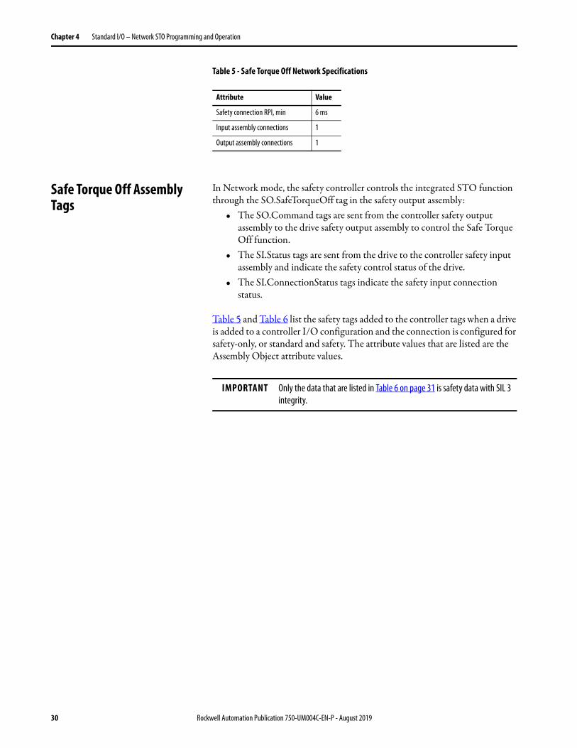
Table 5 - Safe Torque Off Network Specifications
Safe Torque Off Assembly Tags
In Network mode, the safety controller controls the integrated STO function through the SO.SafeTorqueOff tag in the safety output assembly:
• The SO.Command tags are sent from the controller safety output assembly to the drive safety output assembly to control the Safe Torque Off function.
• The SI.Status tags are sent from the drive to the controller safety input assembly and indicate the safety control status of the drive.
• The SI.ConnectionStatus tags indicate the safety input connection status.
Table 5 and Table 6 list the safety tags added to the controller tags when a drive is added to a controller I/O configuration and the connection is configured for safety-only, or standard and safety. The attribute values that are listed are the Assembly Object attribute values.
Attribute Value
Safety connection RPI, min 6 ms
Input assembly connections 1
Output assembly connections 1
IMPORTANT Only the data that are listed in Table 6 on page 31 is safety data with SIL 3 integrity.
30 Rockwell Automation Publication 750-UM004C-EN-P - August 2019

Standard I/O – Network STO Programming and Operation Chapter 4
Table 6 - Integrated STO Specifications
Configure Safe Torque Off in the Logix Designer Application
This chapter provides instructions for how to add and configure an Integrated Safety - Safe Torque Off option module in a PowerFlex 755 drive or PowerFlex 755T drive product in an existing project in the Logix Designer application. This chapter is specific to safety and does not cover all aspects of drive configuration.
Before you can configure your option module in the Logix Designer application:
• You must have a safety controller project with an EtherNet/IP® network connection configured and Time Sync enabled. See the documentation for your controller, drive, and Ethernet adapter for information on configuring those products (see Additional Resources on page 10).
• You must add a drive and option card to your project.
Logix Designer Tag NameAttribute[bit]
Type Description
SI.ConnectionStatus (1) (2) (3) DINT RunMode Status
Connection Fault Status Safety Connection Operation
SI.RunModeSI.ConnectionFault
[0][1]
BOOLBOOL
1 = Run 0 = Valid Data is being controlled by the producing device. The producing device is in Run mode.
0 = Idle 0 = Valid The connection is active and the producing device is in the Idle state. The safety data is reset to zero.
O = Idle 1 = Faulted The safety connection is faulted. The state of the producing device is unknown. The safety data is reset to zero.
1 1 Invalid state.
SI.Status (1) (4) 0x1A0 DINT
SI.TorqueDisabled [0] BOOL0 = Torque Permitted1 = Torque Disabled
SI.SafetyFault [6] BOOL 1 = STO fault present
SI.ResetRequired [7] BOOL 1 = Reset is required
SO.Command (1) (5) 0x180 DINT
SO.SafeTorqueOff [0] BOOL0 = Disable Torque1 = Permit Torque
SO.Reset [7] BOOL 0 --> 1 = Reset STO fault
(1) Bits not listed are always zero.(2) The Safety Validator in the safety controller determines the Connection Status.(3) The first 2 bits of SI.ConnectionStatus contain the SI.RunMode and SI.ConnectionFault status bits of the device. The table describes the combinations of the RunMode and ConnectionFault states.(4) Status is sent from the drive to the controller by using integrated safety protocol.(5) Commands are sent from the controller to the drive by using integrated safety protocol.
ATTENTION: Safety I/O connections and produced/consumed connections cannot be automatically configured to fault the controller if a connection is lost and the system transitions to the safe state. Therefore, if you must detect a module fault to be sure that the system maintains SIL 3, you must monitor the SI.ConnectionStatus bits and initiate the fault via program logic.
Rockwell Automation Publication 750-UM004C-EN-P - August 2019 31

Chapter 4 Standard I/O – Network STO Programming and Operation
To set up your drive with the 20-750-S3 option module, you must configure the following attributes, in addition to the drive’s IP address, revision, ratings, and power structure settings:
The Enable Automatic Device Configuration and Fail Drive Connection on Peripheral Error check boxes cannot be selected, as ADC is not needed to download configuration to the 20-750-S3 option module. This is handled automatically in the Safety Forward open each time the safety connection gets established with the option module.
Depending on the type of drive that you choose, the configuration options may appear on different dialog boxes in the programming software.
Port 4, 5, or 6
Electronic Keying
Exact Match Indicates that all keying attributes must match to establish communication. If any attribute does not match precisely, communication with the device does not occur.
Compatible Module
Lets the installed device accept the key of the device that is defined in the project when the installed device can emulate the defined device. With Compatible Module, you can typically replace a device with another device that has the following characteristics: • Same catalog number• Same or higher Major Revision• Minor Revision as follows:
– If the Major Revision is the same, the Minor Revision must be the same or higher.– If the Major Revision is higher, the Minor Revision can be any number.
Disable Keying
Indicates that the keying attributes are not considered when attempting to communicate with a device. With Disable Keying, communication can occur with a device other than the type specified in the project.
Connection Description Requires Controller Firmware Revision
Standard Control is managed by this controller. Safety is managed by another controller and can be either networked or hardwired.
30.011 or later
Standard and Safety
Both control and network safety connections are managed by this controller. A Standard and Safety connection can only be made from a GuardLogix® controller.
30.012 or later
Safety Only Network safety connection is managed by this controller. Control is managed by another controller. A Safety connection can only be made from a GuardLogix controller.
30.011 or later
ATTENTION: Disable Keying is not permitted for safety devices.
32 Rockwell Automation Publication 750-UM004C-EN-P - August 2019

Standard I/O – Network STO Programming and Operation Chapter 4
Add a PowerFlex 755/755T Drive Product to the Controller Project
1. Right-click Ethernet network and choose New Module.
2. Choose one of the following, and then click Create:
• PowerFlex 755 HiPwr-EENET• PowerFlex 755-EENET• PowerFlex 755T
TIP If you want to use a 20-750-ENETR Dual-port EtherNet/IP option module with the Integrated Safety - Safe Torque Off option module, you must select PowerFlex 755-EENET or PowerFlex 755 HiPwr-EENET from this list. Later in this procedure, you will use the Synchronize command so that the module reflects an ENETR module and will work with the Integrated Safety - Safe Torque Off module.
Rockwell Automation Publication 750-UM004C-EN-P - August 2019 33

Chapter 4 Standard I/O – Network STO Programming and Operation
Add an Option Module to a PowerFlex 755/755T Drive Product in I/O Mode
1. In the Device Definition dialog box, under Identity, enter the Connection type that you want to use. Select from one of the following types. The ‘Standard and Safety’ connection is used in this example.
2. Enter additional Device Definition data (such as Name, Description, and Ethernet Address) for the drive product being used.
Connection Type Description Requires Controller Firmware Revision
Standard Control is managed by this controller. Safety is managed by another controller.
V31 or later
Standard and Safety Both control and network safety connections are managed by this controller. A Standard and Safety connection can only be made from a GuardLogix 5580 or Compact GuardLogix 5380 controller.
V31.012 or later
Safety Only Network safety connection is managed by this controller. Control is managed by another controller. A Safety connection can only be made from a GuardLogix 5580 or Compact GuardLogix 5380 controller.
V31 or later
TIP When the Connection type is ‘Standard and Safety’ or ‘Safety Only’,20-750-S3 appears as the default Safety Peripheral. This is the correct selection for the Integrated Safety - Safe Torque Off option module.
34 Rockwell Automation Publication 750-UM004C-EN-P - August 2019

Standard I/O – Network STO Programming and Operation Chapter 4
Generate the Safety Network Number (SNN)
The assignment of a time-based SNN is automatic when you create a GuardLogix safety controller project and add new Safety I/O devices.
Manual manipulation of an SNN is required in the following situations:• If safety consumed tags are used• If the project consumes safety input data from a device whose
configuration is owned by some other device• If a safety project is copied to another hardware installation within the
same routable Safety system
If an SNN is assigned manually, the SNN has to be unique.
To edit the SNN, follow these steps:
1. In the Device Definition dialog box, click Edit next to the Safety Network Number.
IMPORTANT If you assign an SNN manually, make sure that the system expansion does not result in duplication of SNN and node address combinations.A warning appears if your project contains duplicate SNN and node address combinations. You can still verify the project, but Rockwell Automation recommends that you resolve the duplicate combinations.
Rockwell Automation Publication 750-UM004C-EN-P - August 2019 35

Chapter 4 Standard I/O – Network STO Programming and Operation
2. Select either Time-based or Manual.
• If you select Manual, enter a value from 1…9999 decimal.• If you select Time-based, click Generate SNN. • Click Copy to copy the SNN from the controller, which owns the
safety configuration for the drive module.• Click Paste to paste the SNN from the configuration owner to the
drive module.
3. Click OK on the Edit Safety Network Number dialog box, then click OK on the Device Definition dialog box to add the drive to the project.
Configure Safety Connections
After performing the steps in the preceding sections, additional options are available on the Overview page.
36 Rockwell Automation Publication 750-UM004C-EN-P - August 2019

Standard I/O – Network STO Programming and Operation Chapter 4
This section describes changes that you can make on the Connection page.
1. Select Connection.
2. Adjust the Safety Input Requested Packet Interval (RPI) as desired for your safety system.
IMPORTANT If the drive is used with an induction motor, there is a general rule of no repeated (three or more) start/stops with less than 10 seconds between them (assumes the highest RPI of 500 ms is used). Otherwise a safety connection loss can occur. If less than 10 seconds is needed, a lower RPI can be used per the following formula:RPI (ms) * 19 = Min. Repeated Start/Stop time (seconds)For example, a 50 ms RPI equates to a minimum of 0.95 seconds required between repeated start/stops.
Rockwell Automation Publication 750-UM004C-EN-P - August 2019 37

Chapter 4 Standard I/O – Network STO Programming and Operation
3. Specify additional settings for the Safety Output and Safety Input Connections by clicking Edit next to the Connection Reaction Time Limit.
4. In the Connection Reaction Time Limit dialog box, specify additional settings as required.
38 Rockwell Automation Publication 750-UM004C-EN-P - August 2019

Standard I/O – Network STO Programming and Operation Chapter 4
5. Click OK to close the Connection Reaction Time Limit dialog box.
Advanced Reaction Connection Time Limit Configuration Settings
Description
Requested Packet Interval (RPI)
The RPI specifies the period that data updates over a connection. For example, an input module produces data at the RPI that you assign. For safety input connections, you can set the RPI on the Safety tab of the Module Properties dialog box. The RPI is entered in 1 ms increments, with a range of 6…500 ms. The default is 10 ms.The Connection Reaction Time Limit is adjusted immediately when the RPI is changed via the Logix Designer application. For safety output connections, the RPI is fixed at the safety task period. If the corresponding Connection Time Reaction Limit is not satisfactory, you can adjust the safety task period via the Safety Task Properties dialog box of the safety controller. See the user manual for the controller.For typical applications, the default RPI is sufficient. If you are experiencing nuisance connection timeouts, you can either increase the RPI or increase the Time Multiplier.
Timeout Multiplier
The Timeout Multiplier determines the number of RPIs to wait for a packet before declaring a connection timeout. This value translates into the number of messages that can be lost before a connection error is declared. For example, a Timeout Multiplier of 1 indicates that messages must be received during each RPI interval. A Timeout Multiplier of 2 indicates that one message can be lost as long as at least one message is received in two times the RPI (2 x RPI). If you are experiencing nuisance connection timeouts, you can either increase the Time Multiplier or increase the RPI.
Network Delay Multiplier
The Network Delay Multiplier defines the message transport time that the safety protocol enforces. The Network Delay Multiplier specifies the round-trip delay from the producer to the consumer and the acknowledge back to the producer. You can use the Network Delay Multiplier to reduce or increase the Connection Reaction Time Limit in cases where the enforced message transport time is significantly less or more than the RPI. For example, to adjust the Network Delay Multiplier is helpful when the RPI of an output connection is the same as a lengthy safety task period.
Connection Reaction Time Limit
The Connection Reaction Time Limit is the maximum age of safety packets on the associated connection. If the age of the data that is used by the consuming device exceeds the Connection Reaction Time Limit, a connection fault occurs. The following equations determine the Connection Reaction Time Limit:Input Connection Reaction Time Limit = Input RPI x [Timeout Multiplier + Network Delay Multiplier]Output Connection Reaction Time Limit = Safety Task Period x [Timeout Multiplier + Network Delay Multiplier - 1]
Rockwell Automation Publication 750-UM004C-EN-P - August 2019 39

Chapter 4 Standard I/O – Network STO Programming and Operation
Using a 20-750-ENETR Dual-port EtherNet/IP Option Module with a 20-750-S3 Option Module
When using a PowerFlex 755 drive with 20-750-ENETR and 20-750-S3 option modules, the drive must be added to the Controller Organizer as a PowerFlex 755-EENET module instead of a PowerFlex 755-ENETR module. See page 33 for more information.
1. Make sure that the jumper on the 20-750-ENETR option module is in the Tap position.
2. Click Synchronize from the Connect menu. (The Connection to the PowerFlex 755/755T drive product must be ‘Standard’ or ‘Standard and Safety’ in order for Synchronize option to be selectable.)
3. If necessary, select your drive in the Synchronize - Identifying Device dialog box, and then click Continue.
40 Rockwell Automation Publication 750-UM004C-EN-P - August 2019

Standard I/O – Network STO Programming and Operation Chapter 4
4. After selecting Synchronize, select the check box for Use Physical. This matches the project’s configuration to the physical configuration of the drive.
5. Click Continue.
6. After the synchronization is completed, verify that the 20-750-ENETR option module appears as EtherNet/IP *ENETR (TAP), indicating that the option module is in tap mode.
TIP If you have already configured parameters offline, you can select the Use Project check box associated with the Parameters Category so that your parameters will not be overwritten during the synchronization. Selecting Use Project sets the parameters in the drive to match the parameter configuration of the offline project.
Rockwell Automation Publication 750-UM004C-EN-P - August 2019 41
Chapter 4 Standard I/O – Network STO Programming and Operation
Safety Configuration Signature and Ownership
The connection between the controller and the drive is based on the following criteria:
• Drive catalog number must be for PowerFlex 755 drives, PowerFlex 755TL low harmonic drives, PowerFlex 755TR regenerative drives, or PowerFlex 755TM drive systems
• Drive Safety Network Number (SNN) (displayed on the General tab of the drive’s Module Properties dialog box)
• GuardLogix slot number• GuardLogix safety network number• Path from the GuardLogix safety controller to the PowerFlex 755 drive
or PowerFlex 755T drive product• Configuration signature (displayed on the Safety tab of the drive’s
Module Properties dialog box)
If any differences are detected, the safety connection between the safety controller and the drive is not established (new drive/system) or lost (existing drive/system), and a yellow icon appears next to the drive in the controller project tree. Configuration Ownership has to be reset to establish (new) or re-establish (existing) the connection.
Reset Ownership
To reset ownership, see Restore the Drive to Out-of-Box State on page 26.
42 Rockwell Automation Publication 750-UM004C-EN-P - August 2019

Standard I/O – Network STO Programming and Operation Chapter 4
Safe Torque Off – Stop Category 0 Example Program
This safety task code is an example for a category 0 stop. The STO output is energized if the safety interlocks are satisfied, there are no faults, there is a valid connection, and there is a falling edge on the ‘Safety_Reset’ button.
‘Safety_Reset’ and ‘Safety_Interlocks_OK’ come from elsewhere in the safety program:
• ‘Safety_Reset’ is the user-initiated manual reset action that is used in the safety system
• ‘Safety_Interlocks_OK’ are the safety interlocks that are used with this safety function
The accumulated 'Safety_Interlocks_OK' tag is used in the seal-in rung to drive the STO tag. When a demand is placed on safety interlocks and 'Safety_Interlocks_OK' goes to low (0), then the 20-750-S3 STO output immediately goes to low (0) as well. ‘Safe Torque Off ’ (STO) remains off until a manual reset action is completed after the safety interlocks are satisfied.
Rockwell Automation Publication 750-UM004C-EN-P - August 2019 43

Chapter 4 Standard I/O – Network STO Programming and Operation
Safe Torque Off – Stop Category 1 Example Program
This safety task code is an example for a category 1 stop. The STO output is energized if the safety interlocks are satisfied, there are no faults, there is a valid connection, and there is a falling edge on the ‘Safety_Reset’ button.
‘Safety_Reset’ and ‘Safety_Interlocks_OK’ come from elsewhere in the safety program:
• ‘Safety_Reset’ is the user-initiated manual reset action that is used in the safety system
• ‘Safety_Interlocks_OK’ are the safety interlocks that are used with this safety function
The accumulated 'Safety_Interlocks_OK' tag is used in the seal-in rung to drive the STO tag. When a demand is placed on the safety interlocks, then the 20-750-S3 STO output goes to low (0) after a three-second delay. The risk assessment determines the length of the delay. During the three-second delay, the 'Safety_CAT1_Stop_to_Drive' tag can be used in parallel with other main program stop logic to stop the drive in the main program.
‘Safe Torque Off ’ (STO) remains off until a manual reset action is completed after the safety interlocks are satisfied.
44 Rockwell Automation Publication 750-UM004C-EN-P - August 2019

Standard I/O – Network STO Programming and Operation Chapter 4
Falling Edge Reset
ISO 13849-1 stipulates that instruction reset functions must occur on falling edge signals. To comply with this requirement, a One Shot Falling (OSF) instruction is used on the reset rung. Then, the OSF instruction Output Bit tag is used as the reset bit for the STO output or enable rungs.
Safety Tags in Standard Routines
Tags that are classified as safety tags are either controller-scoped or program-scoped.
• Controller-scoped safety tags are read by either standard or safety logic or other communication devices.
• Controller-scoped safety tags are written only by safety logic or another GuardLogix safety controller.
Program-scoped safety tags are accessible only by local safety routines. These routines reside within the safety program.
Standard Tags in Safety Routines (tag mapping)
Controller-scoped standard tags can be mapped into safety tags, providing a mechanism to synchronize standard and safety actions. In the Logix Designer application, click Logic > Map Safety Tags... to open the Safety Tag Mapping window.
ATTENTION: When using standard data in a safety routine, you are responsible to verify that the data is used in an appropriate manner. The use of standard data in a safety tag does not make it safety data.Do not directly control a safety output with standard tag data.
Rockwell Automation Publication 750-UM004C-EN-P - August 2019 45

Chapter 4 Standard I/O – Network STO Programming and Operation
Safe Torque Off Fault Reset To clear the STO Fault condition, a transition from logic 0 to 1 of the SO.Reset tag is required.
If the drive safety controller detects a fault, the input assembly tag SI.SafetyFault is set to 1.
See Figure 4 on page 46 for an understanding of the PowerFlex 755 drive and PowerFlex 755T drive products state restart functionality.
Figure 4 - Reset Safe Torque Off Fault Diagram
IMPORTANT All PowerFlex 755 drives and PowerFlex 755T drive products enter the faulted state if any STO function fault is detected. See Table 16 on page 83 for integrated safety troubleshooting.
B D EC FA
Disable Torque Permit Torque
No Fault
No Fault
Reset Request
Torque Disabled
Faulted
Reset Required
Faulted
Reset Request
Reset Required
Disable Torque
Torque Disabled
Faulted
Start Inhibited
Faulted
Host Config [P4] Safety Status (bit 0)--->Safety Fault
Host Config [P4] Safety Status (bit 3)--->STO Active
Host Config [P4] Safety Status (bit 4)--->Trq Disabled
Drive Start Inhibits (bit 7)1--->Safety
Drive Fault Status B (bit 9) 2--->SafetyBrdFlt
Host Config [P5] Safety Status (bit 3)--->STO Fault
Host Config [P4] Safety Status (bit 2)--->Restart Req
Host Config [P4] Safety Status (bit 1)--->Safety Reset
SO.SafeTorqueOff (bit 0)
SO.Reset (bit 7)
SI.TorqueDisabled (bit 0)
SI.SafetyFault (bit 6)
SI.ResetRequired (bit 7)
A. Set SO.SafeTorqueOff = 1B. FaultDetected
C. Set SO.SafeTorqueOff = 0D. Set SO.SafeTorqueOff = 1
E. Set SO.ResetRequest = 1F. PF 755 Clear Fault (I/O Mode) or MAFR (CIP Motion™)
1 Drive Start Inhibits is parameter 933 in PowerFlex 755 drives and parameter 603 in PowerFlex 755T drive products.2 Drive Fault Status B is parameter 953 in PowerFlex 755 drives and parameter 462 in PowerFlex 755T drive products.
46 Rockwell Automation Publication 750-UM004C-EN-P - August 2019

Standard I/O – Network STO Programming and Operation Chapter 4
Understand Integrated Safety Drive Replacement
GuardLogix controllers retain I/O device configuration onboard and are able to download the configuration to the replacement device.
Replacing an entire PowerFlex 755 drive or PowerFlex 755T drive product on an integrated safety network is more involved than replacing standard devices because of the safety network number (SNN). The device number and SNN is the safety Device ID of the device. Safety devices require this complex identifier to make sure that duplicate device numbers do not compromise communication between the safety devices. The SNN is also used to provide integrity on the initial download to the PowerFlex 755 drive or PowerFlex 755T drive product.
When the Logix Designer application is online, the Safety tab of the Module Properties dialog box displays the current configuration ownership. When the opened project owns the configuration, Local is displayed.
A communication error is displayed if the module read fails. See Replace an Integrated Safety Drive in a GuardLogix System on page 47 for integrated safety drive replacement examples.
Replace an Integrated Safety Drive in a GuardLogix System
Two options for I/O device replacement are available on the Safety tab of the Controller Properties dialog box in the Logix Designer application:
• Configure Only When No Safety Signature Exists• Configure Always
IMPORTANT If the replacement card/module was used before, clear the existing configuration before installing the card/module on a safety network by resetting the card/module to Hardwired Safe Torque Off mode. See Out-of-Box State on page 26 for more information.
ATTENTION: During replacement or functional testing of a device, the safety of the system must not rely on any portion of the affected device.
IMPORTANT The replacement of safety devices requires that the replacement device is properly configured, and that the proper operation of the replacement device is verified.
Rockwell Automation Publication 750-UM004C-EN-P - August 2019 47

Chapter 4 Standard I/O – Network STO Programming and Operation
Figure 5 - Safety I/O Replacement Options
Configure Only When No Safety Signature Exists
This setting instructs the GuardLogix controller to configure a safety device only when the safety task does not have a safety task signature, and the replacement device is in out-of-box condition. Therefore, a safety network number does not exist in the safety device.
If the safety task has a safety task signature, the GuardLogix controller only configures the replacement Safety I/O device if the following is true:
• The device already has the correct safety network number.• The device electronic keying is correct.• The node or IP address is correct.
For detailed information on how to replace a safety I/O device, see the user manual for the safety controllers listed in the Additional Resources on page 10.
48 Rockwell Automation Publication 750-UM004C-EN-P - August 2019
Standard I/O – Network STO Programming and Operation Chapter 4
Configure Always
The GuardLogix controller always attempts to configure a replacement Safety I/O device if the device is in an out-of-box condition, meaning that a safety network number does not exist in the replacement safety device, and the node number and I/O device keying matches the configuration of the controller.
ATTENTION: Enable the Configure Always feature only if the entire safety control system is not being relied on to maintain SIL 3 behavior during the replacement and functional testing of a device.If other parts of the Safety control system are being relied upon to maintain SIL 3, make sure that the ‘Configure Always’ feature in the controller is disabled.It is your responsibility to implement a process to make sure that proper safety functionality is maintained during device replacement.
ATTENTION: If you place any devices in the out-of-box condition on any safety network when the Configure Always feature is enabled, follow the device replacement procedure in the respective controller user manual listed in the Additional Resources on page 10.
Rockwell Automation Publication 750-UM004C-EN-P - August 2019 49

Chapter 4 Standard I/O – Network STO Programming and Operation
Notes:
50 Rockwell Automation Publication 750-UM004C-EN-P - August 2019

Chapter 5
Integrated Motion – Network STO Programming and Operation
This chapter provides information for network installation and operation of the Integrated Safety - Safe Torque Off option module when used with Integrated Motion.
Requirements The following items are required:• GuardLogix® 5580 or Compact GuardLogix 5380 controller• Studio 5000 Logix Designer® application version 31 (or later)• PowerFlex® 755 v14 firmware (or later)• PowerFlex Integrated Motion profile version 19.00.00 (or later)
Integrated Motion support for PowerFlex 755T drive products is planned for a future drive firmware release.
Description of Operation The Safe Torque Off (STO) feature provides a method, with sufficiently low probability of failure, to force the power-transistor control signals to a disabled state. When the command to execute the STO function is received from the GuardLogix controller, all the drive output-power transistors are released from the ON-state. This results in a condition where the drive is coasting. Disabling the power transistor output does not provide mechanical isolation of the electrical output that is required for some applications.
Topic Page
Requirements 51
Description of Operation 51
Configure Safe Torque Off in the Logix Designer Application 54
Safe Torque Off – Stop Category 0 Example Program 61
Safe Torque Off – Stop Category 1 Example Program 62
Rockwell Automation Publication 750-UM004C-EN-P - August 2019 51

Chapter 5 Integrated Motion – Network STO Programming and Operation
You can use the Safe Torque Off circuit in combination with other safety devices to achieve the stop and protection-against-restart as specified in IEC 60204-1. These conditions must be met for integrated control of the STO function:
• You must have a GuardLogix safety controller project with anEtherNet/IP® network connection configured.
• You must add the PowerFlex drive to the Ethernet network connection in the safety controller I/O tree.
The PowerFlex 755 drive STO function response time is less than 15 ms. Response time for the drive is the delay between the time the drive STO command receives the CIP Safety™ packet with an STO request and the time when motion producing power is removed from the motor.
Table 7 - Safe Torque Off Network Specifications
Safe Torque Off Assembly Tags
In Integrated Safe Torque Off (STO) mode, a GuardLogix 5580 or Compact GuardLogix 5380 safety controller controls the PowerFlex 755 Safe Torque Off function through the SO.SafeTorqueOff tag in the safety output assembly.
The SO.Command tags are sent from the GuardLogix safety output assembly to the PowerFlex 755 safety output assembly to control the Safe Torque Off function.
The SI.Status tags are sent from the PowerFlex 755 to the GuardLogix safety input assembly and indicate the PowerFlex 755 safety control status.
The SI.ConnectionStatus tags indicate the safety input connection status.
Table 8 lists the safety tags added to the controller tags when a PowerFlex 755 drive is added to a GuardLogix I/O configuration and the connection is configured for Motion and Safety or Safety-only.
The attribute values listed are the Assembly Object attribute values.
Attribute Value
Safety connection RPI, min 6 ms
Input assembly connections (1)
(1) Motion and Safety and Safety-only connections with the inverter uses 1 input assembly connection and 1 output assembly connection.
1
Output assembly connections (1) 1
52 Rockwell Automation Publication 750-UM004C-EN-P - August 2019

Integrated Motion – Network STO Programming and Operation Chapter 5
Table 8 - Integrated STO Specifications
Logix Designer Tag NameAttribute[bit]
Type Description
SI.ConnectionStatus (1) (2)
(1) Bits not listed are always zero.(2) ConnectionStatus is determined by the Safety Validator in the GuardLogix controller.
DINTThe ConnectionStatus data type contains RunMode and ConnectionFault status bits.
SI.RunMode [0] BOOL See Table 9 for descriptions of the combinations of the RunMode and ConnectionFault states. SI.ConnectionFault [1] BOOL
SI.Status (1) (3)
(3) Status is sent from the drive to the controller using integrated safety protocol.
0x1A0 SINT
SI.TorqueDisabled [0] BOOL 0 = Torque Permitted1 = Torque Disabled
SI.SafetyFault [6] BOOL 1 = STO fault present
SI.ResetRequired [7] BOOL 1 = Reset is required
SO.Command (1) (4)
(4) Commands are sent from the controller to the drive using integrated safety protocol.
0x180 SINT
SO.SafeTorqueOff [0] BOOL 0 = Disable Permit1 = Permit Torque
SO.Reset [7] BOOL 0 --> 1 = Reset STO fault
IMPORTANT Only the data listed in Table 8 is safety data with SIL 3 integrity.
Table 9 - Safety Connection Status
RunMode Status ConnectionFaulted Status Safety Connection Operation
1 = Run 0 = Valid Data is actively being controlled by the producing device. The producing device is in Run mode.
0 = Idle 0 = Valide The connection is active and the producing device is in the Idle state. The safety data is reset to zero.
0 = Idle 1 = Faulted The safety connection is faulted. The state of the producing device is unknown. The safety data is reset to zero.
1 1 Invalid state.
Rockwell Automation Publication 750-UM004C-EN-P - August 2019 53

Chapter 5 Integrated Motion – Network STO Programming and Operation
Configure Safe Torque Off in the Logix Designer Application
This chapter provides instructions for how to add and configure an Integrated Safety - Safe Torque Off option module in a PowerFlex 755 drive in an existing project in the Logix Designer application. This chapter is specific to safety and does not cover all aspects of drive configuration.
Before you can configure your option module in the Logix Designer application:
• You must have a safety controller project with an EtherNet/IP network connection configured and Time Sync enabled. See the documentation for your controller, drive, and Ethernet adapter for information on configuring those products (see Additional Resources on page 10).
• You must add a drive and option card to your project.
To set up your drive with the 20-750-S3 option card, you must configure the following attributes, in addition to the drive’s IP address, revision, ratings, and power structure settings:
Port Integrated Motion: Port 6 only
Electronic Keying
Exact Match Indicates that all keying attributes must match to establish communication. If any attribute does not match precisely, communication with the device does not occur.
Compatible Module
Lets the installed device accept the key of the device that is defined in the project when the installed device can emulate the defined device. With Compatible Module, you can typically replace a device with another device that has the following characteristics: • Same catalog number• Same or higher Major Revision• Minor Revision as follows:
– If the Major Revision is the same, the Minor Revision must be the same or higher.– If the Major Revision is higher, the Minor Revision can be any number.
Disable Keying
Indicates that the keying attributes are not considered when attempting to communicate with a device. With Disable Keying, communication can occur with a device other than the type specified in the project.
Connection Description Requires ControllerFirmware Revision
Motion Integrated Motion on an EtherNet/IP network is managed by this controller. Safety is managed by another controller and can be either networked or hardwired.
31.000(1) or later for ControlLogix 5570 and GuardLogix 5580
31.000(1) or later for Compact Logix 5370 and Compact GuardLogix 5380
(1) Firmware revision 30.011 can be used if the drive is used in Standard I/O Mode.
Motion and Safety
Integrated Motion on an EtherNet/IP network and integrated STO are managed by this controller. A Motion and Safety connection can only be made from a GuardLogix controller.
31.000 or later for GuardLogix 5580 and Compact GuardLogix 5380
Safety Only Network safety connection is managed by this controller. Control is managed by another controller. A Safety connection can only be made from a GuardLogix controller.
ATTENTION: Disable Keying is not permitted for safety devices.
54 Rockwell Automation Publication 750-UM004C-EN-P - August 2019

Integrated Motion – Network STO Programming and Operation Chapter 5
Add a PowerFlex 755 Drive to the Controller Project
1. Right-click EtherNet network and choose New Module.
2. Select a PowerFlex 755 drive for Integrated Motion on EtherNet/IP networks (selection catalog number ends in –CM-S3 for drives with network STO option).
3. Configure an Option Card on a PowerFlex 755 Drive in Integrated Motion on EtherNet/IP Network Applications as described in the following section.
Rockwell Automation Publication 750-UM004C-EN-P - August 2019 55

Chapter 5 Integrated Motion – Network STO Programming and Operation
Configure an Option Card on a PowerFlex 755 Drive in Integrated Motion on EtherNet/IP Network Applications
1. On the New Module dialog box, name the drive.
2. Type the IP Address.
3. Click Change to edit the Module Definition.
4. On the Module Definition dialog box, configure the drive’s properties:
a. Revisionb. Electronic Keyingc. Power Structured. Connection Type
5. If desired, select the Verify Power Rating on Connection check box to verify the power rating on connection.
56 Rockwell Automation Publication 750-UM004C-EN-P - August 2019

Integrated Motion – Network STO Programming and Operation Chapter 5
6. Click Safety Definition to configure 20-750-S3 revision and Electronic Keying.
7. Click OK to close the Safety Definition dialog box.
8. Click OK to close the Module Definition dialog box.
Note that the Safety Network Number (SNN) is on the General page and that there is a Safety page.
9. Continue with Generate the SNN as described in the following section.
Generate the Safety Network Number (SNN)
The assignment of a time-based SNN is automatic when you create a GuardLogix safety controller project and add new Safety I/O devices.
Manual manipulation of an SNN is required in the following situations:• If safety consumed tags are used• If the project consumes safety input data from a device whose
configuration is owned by some other device• If a safety project is copied to another hardware installation within the
same routable Safety system
If an SNN is assigned manually, the SNN has to be unique.
To edit the SNN, follow these steps.
1. To open the Safety Network Number dialog box, click to the right of the Safety Network Number.
2. Select either Time-based or Manual.
If you select Manual, enter a value from 1…9999 decimal.
IMPORTANT If you assign an SNN manually, make sure that the system expansion does not result in duplication of SNN and node address combinations.A warning appears if your project contains duplicate SNN and node address combinations. You can still verify the project, but Rockwell Automation recommends that you resolve the duplicate combinations.
Rockwell Automation Publication 750-UM004C-EN-P - August 2019 57

Chapter 5 Integrated Motion – Network STO Programming and Operation
3. Click Generate.
4. Click OK.
Configure Safety Connections
To configure the safety tab, follow these steps.
1. Click the Safety tab in the drive Module Properties.
2. Adjust the Safety Input Requested Packet Interval (RPI) as desired for your safety system.
IMPORTANT If the drive is used with an induction motor, there is a general rule of no repeated (three or more) start/stops with less than 10 seconds between them (assumes the highest RPI of 500 ms is used). Otherwise a safety connection loss can occur. If less than 10 seconds is needed, a lower RPI can be used per the following formula:RPI (ms) * 19 = Min. Repeated Start/Stop time (seconds)For example, a 50 ms RPI equates to a minimum of 0.95 seconds required between repeated start/stops.
58 Rockwell Automation Publication 750-UM004C-EN-P - August 2019

Integrated Motion – Network STO Programming and Operation Chapter 5
3. Click Advanced… for more advanced settings.
4. Configure the advanced settings as desired.
5. Click OK.
Advanced Reaction Connection Time Limit Configuration Settings
Description
Requested Packet Interval (RPI)
The RPI specifies the period that data updates over a connection. For example, an input module produces data at the RPI that you assign. For safety input connections, you can set the RPI on the Safety tab of the Module Properties dialog box. The RPI is entered in 1 ms increments, with a range of 6…500 ms. The default is 10 ms.The Connection Reaction Time Limit is adjusted immediately when the RPI is changed via the Logix Designer application. For safety output connections, the RPI is fixed at the safety task period. If the corresponding Connection Time Reaction Limit is not satisfactory, you can adjust the safety task period via the Safety Task Properties dialog box of the safety controller. See the user manual for the controller.For typical applications, the default RPI is sufficient.
Timeout Multiplier
The Timeout Multiplier determines the number of RPIs to wait for a packet before declaring a connection timeout. This value translates into the number of messages that can be lost before a connection error is declared. For example, a Timeout Multiplier of 1 indicates that messages must be received during each RPI interval. A Timeout Multiplier of 2 indicates that one message can be lost as long as at least one message is received in two times the RPI (2 x RPI).
Network Delay Multiplier
The Network Delay Multiplier defines the message transport time that the safety protocol enforces. The Network Delay Multiplier specifies the round-trip delay from the producer to the consumer and the acknowledge back to the producer. You can use the Network Delay Multiplier to reduce or increase the Connection Reaction Time Limit in cases where the enforced message transport time is significantly less or more than the RPI. For example, to adjust the Network Delay Multiplier is helpful when the RPI of an output connection is the same as a lengthy safety task period.
Connection Reaction Time Limit
The Connection Reaction Time Limit is the maximum age of safety packets on the associated connection. If the age of the data that is used by the consuming device exceeds the Connection Reaction Time Limit, a connection fault occurs. The following equations determine the Connection Reaction Time Limit:Input Connection Reaction Time Limit = Input RPI x [Timeout Multiplier + Network Delay Multiplier]Output Connection Reaction Time Limit = Safety Task Period x [Timeout Multiplier + Network Delay Multiplier - 1]
Rockwell Automation Publication 750-UM004C-EN-P - August 2019 59

Chapter 5 Integrated Motion – Network STO Programming and Operation
Safety Configuration Signature and Ownership
The connection between the controller and the drive is based on the following criteria:
• Drive catalog number must be for PowerFlex 755 drives• Drive Safety Network Number (SNN) (displayed in the drive’s Module
Properties dialog box.)• GuardLogix slot number• GuardLogix safety network number• Path from the GuardLogix 5580 safety controller or Compact
GuardLogix 5380 safety controller to the PowerFlex 755 drive • Configuration signature (displayed on the Safety tab of the drive
Module Properties dialog box)
If any differences are detected, the safety connection between the safety controller and the drive is not established (new drive/system) or lost (existing drive/system), and a yellow icon appears next to the drive in the controller project tree. Configuration Ownership has to be reset to establish (new) or re-establish (existing) the connection.
Reset Ownership
To reset ownership, see Restore the Drive to Out-of-Box State on page 26.
60 Rockwell Automation Publication 750-UM004C-EN-P - August 2019

Integrated Motion – Network STO Programming and Operation Chapter 5
Safe Torque Off – Stop Category 0 Example Program
This safety task code is an example for a category 0 stop. The STO output is energized if the safety interlocks are satisfied, there are no faults, there is a valid connection, and there is a falling edge on the ‘Safety_Reset’ button.
‘Safety_Reset’ and ‘Safety_Interlocks_OK’ come from elsewhere in the safety program:
• ‘Safety_Reset’ is the user-initiated manual reset action that is used in the safety system
• ‘Safety_Interlocks_OK’ are the safety interlocks that are used with this safety function
The accumulated 'Safety_Interlocks_OK' tag is used in the seal-in rung to drive the STO tag. When a demand is placed on safety interlocks and 'Safety_Interlocks_OK' goes to low (0), then the 20-750-S3 STO output immediately goes to low (0) as well. ‘Safe Torque Off ’ (STO) remains off until a manual reset action is completed after the safety interlocks are satisfied.
Rockwell Automation Publication 750-UM004C-EN-P - August 2019 61

Chapter 5 Integrated Motion – Network STO Programming and Operation
Safe Torque Off – Stop Category 1 Example Program
This safety task code is an example for a category 1 stop. The STO output is energized if the safety interlocks are satisfied, there are no faults, there is a valid connection, and there is a falling edge on the ‘Safety_Reset’ button.
‘Safety_Reset’ and ‘Safety_Interlocks_OK’ come from elsewhere in the safety program:
• ‘Safety_Reset’ is the user-initiated manual reset action that is used in the safety system
• ‘Safety_Interlocks_OK’ are the safety interlocks that are used with this safety function
The accumulated 'Safety_Interlocks_OK' tag is used in the seal-in rung to drive the STO tag. When a demand is placed on the safety interlocks, then the 20-750-S3 STO output goes to low (0) after a three-second delay. The risk assessment determines the length of the delay. During the three-second delay, the 'Safety_CAT1_Stop_to_Drive' tag can be used in parallel with other main program stop logic to stop the drive in the main program.
‘Safe Torque Off ’ (STO) remains off until a manual reset action is completed after the safety interlocks are satisfied.
Falling Edge Reset
ISO 13849-1 stipulates that instruction reset functions must occur on falling edge signals. To comply with this requirement, a One Shot Falling (OSF)
62 Rockwell Automation Publication 750-UM004C-EN-P - August 2019

Integrated Motion – Network STO Programming and Operation Chapter 5
instruction is used on the reset rung. Then, the OSF instruction Output Bit tag is used as the reset bit for the STO output or enable rungs.
Safety Tags in Standard Routines
Tags that are classified as safety tags are either controller-scoped or program-scoped.
• Controller-scoped safety tags are read by either standard or safety logic or other communication devices.
• Controller-scoped safety tags are written only by safety logic or another GuardLogix safety controller.
Program-scoped safety tags are accessible only by local safety routines. These routines reside within the safety program.
Standard Tags in Safety Routines (tag mapping)
Controller-scoped standard tags can be mapped into safety tags, providing a mechanism to synchronize standard and safety actions. In the Logix Designer application, click Logic > Map Safety Tags... to open the Safety Tag Mapping window.
ATTENTION: When using standard data in a safety routine, you are responsible to verify that the data is used in an appropriate manner. The use of standard data in a safety tag does not make it safety data.Do not directly control a safety output with standard tag data.
Rockwell Automation Publication 750-UM004C-EN-P - August 2019 63

Chapter 5 Integrated Motion – Network STO Programming and Operation
STO Fault Reset
To clear the STO Fault condition, a transition from logic 0 to 1 of the SO.Reset tag is required.
If the PowerFlex 755 drive safety controller detects a fault, the input assembly tag SI.SafetyFault is set to 1.
To reset an Axis.SafetyFault, a Motion Axis Fault Reset (MAFR) command must be issued.
See Figure 6 for an understanding of the PowerFlex 755 STO state restart functionality.
Figure 6 - Reset Safe Torque Off Fault Diagram
IMPORTANT The PowerFlex drive will enter the faulted state if a STO function fault is detected. See Table 10 for integrated safety troubleshooting.
B D EC FA
Disable Torque Permit Torque
No Fault
No Fault
Reset Request
Torque Disabled
Faulted
Reset Required
Faulted
Reset Request
Reset Required
Disable Torque
Torque Disabled
Faulted
Start Inhibited
Faulted
Axis.SafetyFaultStatus
Axis.SafeTorqueActiveStatus
Axis.SafeTorqueDisabledStatus
Asix.SafeTorqueOffActiveInhibit
Axis. SafetyFault
Axis.SafeTorqueOffFault
Axis.SafetyResetRequestStatus
Axis.SafetyResetRequestStatus
SO.SafeTorqueOff (bit 0)
SO.Reset (bit 7)
SI.TorqueDisabled (bit 0)
SI.SafetyFault (bit 6)
SI.ResetRequired (bit 7)
A. Set SO.SafeTorqueOff = 1B. FaultDetected
C. Set SO.SafeTorqueOff = 0D. Set SO.SafeTorqueOff = 1
E. Set SO.ResetRequest = 1F. PF 755 Clear Fault (I/O Mode) or MAFR (CIP Motion)
64 Rockwell Automation Publication 750-UM004C-EN-P - August 2019

Integrated Motion – Network STO Programming and Operation Chapter 5
Troubleshoot the Safe Torque Off Function
Table 10 - PowerFlex 755 Integrated STO
Understand Integrated Safety Drive Replacement
GuardLogix controllers retain I/O device configuration onboard and are able to download the configuration to the replacement device.
Replacing a PowerFlex 755 drive that is on an integrated safety network is more complicated than replacing standard devices because of the safety network number (SNN). The device number and SNN make up the safety device’s DeviceID. Safety devices require this more complex identifier to make sure that duplicate device numbers do not compromise communication between the correct safety devices. The SNN is also used to provide integrity on the initial download to the drive.
When the Logix Designer application is online, the Safety tab of the Module Properties dialog box displays the current configuration ownership. When the opened project owns the configuration, Local is displayed.
A communication error is displayed if the module read fails. See Replace an Integrated Safety Drive in a GuardLogix System on page 66 for integrated safety drive replacement information.
Fault Message Logix Designer Problem Possible Solutions
SafetyFault Drive safety diagnostic detected internal STO design failure.
• Cycle drive control power• Return drive and/or option module for repair if fault continues
SafeTorqueOffFault (1)Drive safety diagnostic detected internal STO design failure or hardwired input received while in integrated safety mode.
• Check the cause of the fault using an MSG instruction. See Safe Torque Off Faults on page 86.• Remove any connection to the hardwired safety inputs and reset using the STO Fault Reset
procedure. See STO Fault Reset on page 64.• Execute STO function.• Return drive and/or option module for repair if fault continues.
InvalidSafetyFirmwareFault (2) Invalid safety firmware.
• Cycle control power.• Upgrade the drive firmware.• Call Technical Support.• Return drive for repair if fault continues.
(1) Displayed in the Quick View Pane as Safety Fault.(2) Displayed in the Quick View Pane as Initialization Fault.
IMPORTANT If the replacement option module was used previously, clear the existing configuration before installing it on a safety network. See Out-of-Box State on page 26.
Rockwell Automation Publication 750-UM004C-EN-P - August 2019 65

Chapter 5 Integrated Motion – Network STO Programming and Operation
Replace an Integrated Safety Drive in a GuardLogix System
When you replace an integrated safety drive, the replacement device must be configured properly and the replacement drives operation be user-verified.
Two options for safety drive replacement are available on the Safety tab of the Controller Properties dialog box in the Logix Designer application:
• Configure Only When No Safety Signature Exists• Configure Always
Figure 7 - Safety Drive Replacement Options
Configure Only When No Safety Signature Exists
This setting instructs the GuardLogix controller to automatically configure a safety drive only when the safety task does not have a safety task signature, and the replacement drive is in an out-of-box condition, meaning that a safety network number does not exist in the safety drive.
If the safety task has a safety task signature, the GuardLogix controller automatically configures the replacement CIP Safety I/O device only if the following is true:
• The device already has the correct safety network number.• The device electronic keying is correct.• The node or IP address is correct.
For details, see information about replacing a safety I/O device in the GuardLogix 5580 Controllers User Manual, publication 1756-UM543 or Compact GuardLogix 5380 Controllers User Manual, publication 5069-UM001.
ATTENTION: During drive replacement or functional test, the safety of the system must not rely on any portion of the affected drive.
66 Rockwell Automation Publication 750-UM004C-EN-P - August 2019

Integrated Motion – Network STO Programming and Operation Chapter 5
Configure Always
When the Configure Always feature is enabled, the controller automatically checks for and connects to a replacement drive that meets all of the following requirements:
• The controller has configuration data for a compatible drive at that network address
• The drive is in Hardwired STO mode or has an SNN that matches the configuration
Motion Direct Commands in Motion Control Systems
You can use the Motion Direct Command (MDC) feature to initiate motion while the controller is in Program mode, independent of application code that is executed in Run mode. These commands let you perform various functions, for example, move an axis, jog an axis, or home an axis.
A typical use might involve a machine integrator testing different parts of the motion system while the machine is being commissioned or a maintenance engineer, under certain restricted scenarios in accordance with safe machine operating procedures, wanting to move an axis (like a conveyor) to clear a jam before resuming normal operation.
ATTENTION: Enable the Configure Always feature only if the entire integrated safety control system is not being relied on to maintain SIL 3 behavior during the replacement and functional testing of a PowerFlex 755 drive. If other parts of the integrated safety control system are being relied upon to maintain SIL 3, make sure that the controller’s Configure Always feature is disabled.It is your responsibility to implement a process to make sure proper safety functionality is maintained during device replacement.
ATTENTION: Do not place any devices in the out-of-box condition on any integrated safety network when the Configure Always feature is enabled, except while following the device replacement procedure in the GuardLogix user manual appropriate for your Logix5000 controller:• GuardLogix 5580 Controllers User Manual, publication 1756-UM543 • Compact GuardLogix 5580 Controllers User Manual, publication 5069-UM001
Rockwell Automation Publication 750-UM004C-EN-P - August 2019 67

Chapter 5 Integrated Motion – Network STO Programming and Operation
Understand STO Bypass When Using Motion Direct Commands
If a Safety-only connection between the GuardLogix safety controller and the PowerFlex 755 drive was established at least once after the drive was received from the factory, the drive does not allow motion while the safety controller is in Program mode by default.
This is because the safety task is not executed while the GuardLogix safety controller is in Program mode. This applies to applications running in a single-safety controller (with Motion and Safety connections). When an integrated safety drive has a Motion connection to a standard controller and a separate Safety connection to a dual-safety controller, the standard controller can transition to Program mode while the safety controller stays in Run mode and continues to execute the safety task.
However, PowerFlex 755 drive systems are designed with a bypass feature for the STO function in single-safety controller configurations. You can use the MDC feature to allow motion while following all the necessary and prescribed steps per your machine’s safety operating procedures.
ATTENTION: To avoid personal injury or damage to equipment, follow these rules regarding Run mode and Program mode.• Only authorized, trained personnel with knowledge of safe machine
operation should be allowed to use Motion Direct Commands• Additional supervisory methods, like removing the controller key switch,
should be used to maintain the safety integrity of the system after returning the safety controller to RUN mode
ATTENTION: Consider the consequences of allowing motion through the use of MDC when the controller is in Program mode. You must acknowledge warning messages in the Logix Designer application that warn of the drive bypassing the STO function and unintended motion can occur. The integrated safety drive does not respond to requests of the STO function if MDC mode is entered.It is your responsibility to maintain machine safety integrity while executing motion direct commands. One alternative is to provide ladder logic for Machine Maintenance mode that leaves the controller in Run mode with safety functions executing.
68 Rockwell Automation Publication 750-UM004C-EN-P - August 2019

Integrated Motion – Network STO Programming and Operation Chapter 5
Logix Designer Application Warning Messages
When the controller is in Run mode, executing safety functions, the PowerFlex 755 drive follows the commands that it receives from the safety controller. The controller reports Safety State = Running and Axis State = Stopped/Running, as shown in Figure 8.
Figure 8 - Safety State Indications When Controller is in Run Mode (safety task executing)
When the controller transitions to Program mode, the integrated safety drive is in the safe state (torque is not permitted). The controller reports Safety State = Not Running and Axis State = Start Inhibited, as shown in Figure 9).
Figure 9 - Safety State Indications After Controller Transitions to Program Mode
Rockwell Automation Publication 750-UM004C-EN-P - August 2019 69

Chapter 5 Integrated Motion – Network STO Programming and Operation
When you issue a motion direct command to an axis to produce torque in Program mode, for example MSO or MDS, with the safety connection present to the drive, a warning message is presented before the motion direct command is executed, as shown in Figure 10.
Figure 10 - STO Bypass Prompt When the Safety Controller is in Program Mode
After you acknowledge the warning message by clicking Yes, torque is permitted by the drive and a warning message is indicated in the software as shown in Figure 11. The controller reports Safety State = Not Running (Torque Permitted), Axis State = Stopped/Running and Persistent Warning = Safe Torque Off Bypassed.
IMPORTANT The warning in Figure 10 is displayed only the first time a motion direct command is issued.
IMPORTANT Switch the controller to Run mode to exit Motion Direct Command mode and end the STO function bypass.
70 Rockwell Automation Publication 750-UM004C-EN-P - August 2019

Integrated Motion – Network STO Programming and Operation Chapter 5
Figure 11 - Safety State Indications After Controller Transitions to Program Mode (MDC executing)
IMPORTANT The persistent warning message text Safe Torque Off bypassed appears when a motion direct command is executed. The warning message persists even after the dialog is closed and reopened as long as the integrated safety drive is in STO Bypass mode.The persistent warning message is removed only after the integrated safety drive's Safety State is restored to the Running state.
Rockwell Automation Publication 750-UM004C-EN-P - August 2019 71

Chapter 5 Integrated Motion – Network STO Programming and Operation
Torque Permitted in a Multi-workstation Environment
The warning in Figure 12 is displayed to notify a second user working in a multi-workstation environment that the first user has placed the integrated safety drive in the STO state and that the current action is about to bypass the STO state and permit torque.
Figure 12 - STO Bypass Prompt When MDC is Issued in Multi-workstation Environment
Warning Icon and Text in Axis Properties
In addition to the other warnings that require your acknowledgement, the Logix Designer application also provides warning icons and persistent warning messages in other Axis Properties dialog boxes when the integrated safety drive is in STO Bypass mode.
Figure 13 - Axis and Safe State Indications on the Hookup Services Dialog Box
Figure 14 - Axis and Safe State Indications on Motion Direct Commands Dialog Box
72 Rockwell Automation Publication 750-UM004C-EN-P - August 2019

Integrated Motion – Network STO Programming and Operation Chapter 5
Figure 15 - Axis and Safe State Indications on the Motion Console Dialog Box
Functional Safety Considerations
ATTENTION: Before maintenance work can be performed in Program mode, the developer of the application must consider the implications of allowing motion through motion direct commands and should consider developing logic for runtime maintenance operations to meet the requirements of machine safety operating procedures.
ATTENTION: Motion is allowed and the STO function is not available when motion direct commands are used in Program mode.Motion direct commands issued when the controller is in Program mode cause the drive to bypass the STO Active condition.It is your responsibility to implement additional preventive measures to maintain safety integrity of the machinery during execution of motion direct commands in Program mode.
ATTENTION: To avoid personal injury and damage to equipment in the event of unauthorized access or unexpected motion during authorized access, return the controller to Run mode and remove the key before leaving the machine unattended.
Rockwell Automation Publication 750-UM004C-EN-P - August 2019 73

Chapter 5 Integrated Motion – Network STO Programming and Operation
Notes:
74 Rockwell Automation Publication 750-UM004C-EN-P - August 2019

Chapter 6
Hardwired STO Wiring and Operation
This chapter provides information for hardwired installation and operation of the Integrated Safety - Safe Torque Off option module.
Wiring Observe these wiring guidelines when installing the safety option module:• Use copper wire with an insulation rating of 600V or greater.• Separate control wires from power wires by at least 0.3 m (1 ft).
Table 11 - Safety Option Module Terminal Block Specifications
Table 12 - TB2 Terminal Designation
Topic Page
Wiring 75
Description of Hardwired Operation 77
Selection of Hardwired Operation 77
Configure the Drive with Hardwired Safety Connections 77
Timing Diagrams 78
Wire Size Range Wire Type Strip Length
Max Min
0.8 mm2 (18 AWG)
0.3 mm2 (28 AWG)
Multi-conductor shielded cable
10 mm(0.39 in.)
Terminal Name Description
Si0 Safety input 0 Safety input 0
SC Safety common Safety power common
Si1 Safety input 1 Safety input 1
SC Safety common Safety power common
SP Safety power +24V DC from customer-supplied SELV/PELV safety power
Safety Input Connection ExamplePower supply
Integrated Safety - Safe Torque Off Option Module (catalog number 20-750-S3)
TB2
These tabs are only for Rockwell Automation use.
SiOSCSi1SCSP
SiOSCSi1SCSP
24V DCSELV/PELV
Supply
Safety Input 0Safety Common
Safety Input 1Safety Common
Safety Power
Rockwell Automation Publication 750-UM004C-EN-P - August 2019 75

Chapter 6 Hardwired STO Wiring and Operation
Cabling• Safety input wiring must be protected against external damage by cable
ducts, conduit, armored cable, or other means.• Shielded cable is required. For proper shield termination, follow the
installation requirements that are related to EN 61800-3 and the EMC Directive as described in these publications:– PowerFlex® 755 AC Drive Installation Instructions,
publication 750-IN001 – PowerFlex 750-Series Products with TotalFORCE™ Control
Installation Instructions, publication 750-IN100
Power Supply Requirements• The external power supply must conform to the Directive 2006/95/EC
Low Voltage, by applying the requirements of EN61131-2 Programmable Controllers, Part 2 - Equipment Requirements and Tests, and one of the following:– EN60950 - SELV (Safety Extra Low Voltage)– EN60204 - PELV (Protective Extra Low Voltage)– IEC 60536 Safety Class III (SELV or PELV)– UL 508 Limited Voltage Circuit– 24V DC ±10% must be supplied by a power supply that complies
with IEC 60204 and IEC 61558-1.For more information, see the guidelines in Industrial Automation Wiring and Grounding Guidelines, publication 1770-4.1.
IMPORTANT The National Electrical Code and local electrical codes take precedence over the values and methods provided.
76 Rockwell Automation Publication 750-UM004C-EN-P - August 2019

Hardwired STO Wiring and Operation Chapter 6
Description of Hardwired Operation
The Safe Torque Off feature provides a method, with sufficiently low probability of failure, to force the power-transistor control signals to a disabled state. If either hardwired safety input is de-energized, the drive output-power transistors are released from the On state. This release results in a condition where the drive coasts (stop category 0). Disabling the power transistor output does not provide mechanical isolation of the electrical output that is required for some applications.
Under normal operation, the Safe Torque Off inputs are energized. If either of the safety enable inputs are de-energized, then the output power transistors turn off. Parameter 933 [Start Inhibits] will indicate that IGBTs are inhibited and the HIM will indicate that the drive is not enabled.
Selection of Hardwired Operation
To select hardwired control of Safe Torque Off:• The safety control must be in the out-of-box state. See Restore the Drive
to Out-of-Box State on page 26.• An appropriate safety device must be connected to terminals Si0, Si1,
and SP.
Configure the Drive with Hardwired Safety Connections
To add the 20-750-S3 peripheral device, and configure the safety connection, see these sections:
• Add an Option Module to a PowerFlex 755/755T Drive Product in I/O Mode on page 34
• Generate the Safety Network Number (SNN) on page 35
ATTENTION: If any of the safety enable inputs de-energize, the Start Inhibit field indicates SafeTorqueOffInhibit. The input must be de-energized within 1 second and re-energized within 1 second to avoid a fault condition.See Figure 6 on page 64.
Rockwell Automation Publication 750-UM004C-EN-P - August 2019 77

Chapter 6 Hardwired STO Wiring and Operation
Timing Diagrams Figure 16 is a timing diagram for normal operation.
Figure 16 - System Operation When Inputs Are Meeting Timing Requirements
A C DB
0 .90 .9
24V
24V
No Fault
Torque Disabled
Disable Torque
Request Stop
No Fault
8 = Waiting
No Fault
Disable Torque
Torque Disabled
Start Inhibited
No Fault
51 = Wait w Trq51 = Wait w Trq
(Safety Input) TB1--->Si1
(Safety Input) TB1--->Si0
Host Config [P1] Guard Status (bit 0)--->Status OKAxis.GuardOKStatus
Host Config [P1] Guard Status (bit 1)--->MP OutAxis.GateDriveOutputStatus
Host Config [P1] Guard Status (bit 2)--->SS InAxis.SafeStopInputStatus
Host Config [P1] Guard Status (bit 3)--->SS ReqAxis.SafeStopRequestStatus
Host Config [P2] Guard Faults (bit 9)--->SS In FltAxis.GuardStopInputFault
Host Config [P3] Safety StateAxis.SafetyState
Host Config [P4] Safety Status (bit 0)--->Safety FaultAxis.SafetyFaultStatus
Host Config [P4] Safety Status (bit 3)--->STO ActiveAxis.SafeTorqueOffActiveStatus
Host Config [P4] Safety Status (bit 4)--->Trq DisabledAxis.SafeTorqueDisabledStatus
Drive Start Inhibits (bit 7)1--->SafetyAxis.SafeTorqueOffInhibit
Drive Fault Status B (bit 9)2--->SafetyBrdFltAxis.GuardFault
A. Set Safety Input Si0 = 0 voltsB. Set Safety Input Si1 = 0 volts within 0.9 seconds
C. Set Safety Input Si0 = 24 voltsD. Set Safety Input Si1 = 0 volts within 0.9 seconds
1 Drive Start Inhibits is parameter 933 in PowerFlex 755 drives and parameter 603 in PowerFlex 755T drive products.2 Drive Fault Status B is parameter 953 in PowerFlex 755 drives and parameter 462 in PowerFlex 755T drive products.
78 Rockwell Automation Publication 750-UM004C-EN-P - August 2019

Hardwired STO Wiring and Operation Chapter 6
Figure 17 demonstrates when a Safe Torque Off safety input mismatch is detected and a Fault is posted.
Figure 17 - System Operation in the Event That the Safety Enable Inputs Mismatch
0.9
A C DB GE F
0.91.0
24V
24V
No FaultFaulted
Torque Disabled
Disable Torque
Request Stop
Faulted
8 = Waiting
Faulted
Disable Torque
Torque Disabled
Start Inhibited
Faulted
51 51 = Wait w Trq
A. Set Safety Input Si0 = 0 voltsB. Discrepancy fault after 0.9 seconds C. Set Safety Input Si1 = 0 volts
Host Config [P1] Guard Status (bit 0)--->Status OKAxis.GuardOKStatus
Host Config [P1] Guard Status (bit 1)--->MP OutAxis.GateDriveOutputStatus
Host Config [P1] Guard Status (bit 2)--->SS InAxis.SafeStopInputStatus
Host Config [P1] Guard Status (bit 3)--->SS ReqAxis.SafeStopRequestStatus
Host Config [P2] Guard Faults (bit 9)--->SS In FltAxis.GuardStopInputFault
Host Config [P3] Safety StateAxis.SafetyState
Host Config [P4] Safety Status (bit 0)--->Safety FaultAxis.SafetyFaultStatus
Host Config [P4] Safety Status (bit 3)--->STO ActiveAxis.SafeTorqueOffActiveStatus
Host Config [P4] Safety Status (bit 4)--->Trq DisabledAxis.SafeTorqueDisabledStatus
Drive Start Inhibits (bit 7)1--->SafetyAxis.SafeTorqueOffInhibit
Drive Fault Status B (bit 9)2--->SafetyBrdFltAxis.GuardFault
(Safety Input) TB1--->Si1
(Safety Input) TB1--->Si0
D. Discrepancy fault cleared after 1.0 secondE. Set Safety Input Si0 = 24 volts
F. Set Safety Input Si1 = 24 voltsG. PF 755 Clear Fault (I/O Mode)
1 Drive Start Inhibits is parameter 933 in PowerFlex 755 drives and parameter 603 in PowerFlex 755T drive products.2 Drive Fault Status B is parameter 953 in PowerFlex 755 drives and parameter 462 in PowerFlex 755T drive products.
Rockwell Automation Publication 750-UM004C-EN-P - August 2019 79

Chapter 6 Hardwired STO Wiring and Operation
Both Safe Torque Off safety inputs must turn off together, otherwise a fault is asserted. Figure 18 shows the timing diagram when the safety inputs mismatch momentarily. A fault will be asserted even if the first safety input gets turned on again.
Figure 18 - System Operation in the Event That the Safety Enable Inputs Mismatch Momentarily
0.9
A C DB GE F
0.91.0
24V
24V
No FaultFaulted
Torque Disabled
Disable Torque
Request Stop
Faulted
8 = Waiting
Faulted
Disable Torque
Torque Disabled
Start Inhibited
Faulted
51 51 = Wait w Trq
(Safety Input) TB1--->Si1
(Safety Input) TB1--->Si0
Host Config [P1] Guard Status (bit 0)--->Status OKAxis.GuardOKStatus
Host Config [P1] Guard Status (bit 1)--->MP OutAxis.GateDriveOutputStatus
Host Config [P1] Guard Status (bit 2)--->SS InAxis.SafeStopInputStatus
Host Config [P1] Guard Status (bit 3)--->SS ReqAxis.SafeStopRequestStatus
Host Config [P2] Guard Faults (bit 9)--->SS In FltAxis.GuardStopInputFault
Host Config [P3] Safety StateAxis.SafetyState
Host Config [P4] Safety Status (bit 0)--->Safety FaultAxis.SafetyFaultStatus
Host Config [P4] Safety Status (bit 3)--->STO ActiveAxis.SafeTorqueOffActiveStatus
Host Config [P4] Safety Status (bit 4)--->Trq DisabledAxis.SafeTorqueDisabledStatus
Drive Start Inhibits (bit 7)1--->Safety
Drive Fault Status B (bit 9)--->2SafetyBrdFlt
A. Set Safety Input Si0 = 0 volts for > 0.1 secondsB. Discrepancy fault after 0.9 seconds C. Set Safety Input Si1 = 0 volts
D. Discrepancy fault cleared after 1.0 secondE. Set Safety Input Si0 = 24 volts
F. Set Safety Input Si1 = 24 voltsG. PF 755 Clear Fault (I/O Mode)
1 Drive Start Inhibits is parameter 933 in PowerFlex 755 drives and parameter 603 in PowerFlex 755T drive products.2 Drive Fault Status B is parameter 953 in PowerFlex 755 drives and parameter 462 in PowerFlex 755T drive products.
ATTENTION: The STO fault is detected upon demand of the STO function. After troubleshooting, a safety function must be executed to verify correct operation.
IMPORTANT A discrepancy STO fault type (102) can be reset by placing both inputs in the off state for more than one second. Any other STO fault types can only be cleared in hardwired STO mode by power cycling or resetting the device.
80 Rockwell Automation Publication 750-UM004C-EN-P - August 2019

Chapter 7
Monitoring and Troubleshooting
This chapter provides information for monitoring and troubleshooting the Integrated Safety - Safe Torque Off option module.
Monitor STO Status The option module has three status indicators to provide status of the module, safety network, and motion output of the drive. When viewing the installed option module, the status indicators are arranged in this order (top to bottom):
• Module status (DS1)• Network status (DS2)• Motion output status (DS3)
Module Status Indicator (DS1)
Table 13 provides information for the module status.
Table 13 - Module Status LED (DS1)
Topic Page
Monitor STO Status 81
Monitor STO With a HIM or Software 83
IMPORTANT Status indicators are not reliable for safety functions. Use status indicators only for general diagnostics during commissioning or troubleshooting. Do not attempt to use status indicators to determine operational status.
For Safety Supervisor State (1)
(1) The numbers in parentheses are the values in the Host Config P[3] Safety State parameter.
Status Indicator Problem
No power Off No power is applied to drive.
Executing (4) Green Drive is operational. No faults or failures.
Idle state (2) Flashing green Standby (drive not configured).
Abort (5) Flashing red Major recoverable fault. The drive detected a recoverable fault.
Critical fault (6) Red The drive detected a non-recoverable fault.
Device self-test (1)Waiting (8)Configuring
Flashing red/green The drive performs self-test during power-up.
Firmware update in progress Flashing red Firmware update in progress.
Rockwell Automation Publication 750-UM004C-EN-P - August 2019 81

Chapter 7 Monitoring and Troubleshooting
Network Status Indicator (DS2)
Table 14 provides information for the network status.
Table 14 - Network Status LED (DS2)
Motion Output Status Indicator (DS3)
Table 15 provides information for the motion output status.
Table 15 - Motion Output Status LED (DS3)
State Status Indicator Problem
Not powered/not online Off Device is not online.
No connections Flashing green Device is online but has no connections in the established state.
Connected Green Device is online and connections in the established state.
Connection timeout Flashing red One or more I/O connections are in the Timed-Out state.
Critical link failure Red Failed communication device. The device has detected an error that has rendered it incapable of communicating on the network.
Self-test Flashing red/green The device is performing its power-on test.
Firmware update in progress Flashing red Firmware update in progress.
State Status Indicator Problem
Torque disabled Off Torque is disabled.
Torque permitted Solid green The STO circuit is permitting torque.
Circuit fault Flashing red The STO circuit is faulted.
82 Rockwell Automation Publication 750-UM004C-EN-P - August 2019

Monitoring and Troubleshooting Chapter 7
Monitor STO With a HIM or Software
This section describes safety-related status information available for viewing with a HIM, drive module properties in the Logix Designer application, or Connected Components Workbench™ software.
Fault Messages on HIM, Drive Module, and Connected Components Workbench Software
The only message displayed for any fault originating from the option card is ‘SAFETY BRD FAULT’ with a fault code of 211. This fault is displayed by the HIM, drive module, and Connected Components Workbench software. To determine the cause of the fault, read the value from STO Fault Type [P7] and see Table 16 to determine possible troubleshooting steps based on fault type.
Table 16 - STO Fault Messages
STO Fault Type(Value) Problem Possible Solutions
Circuit Err(3) Internal STO diagnostics has found an issue with STO circuitry.
• Cycle power (or perform fault reset if in network mode).
• Execute STO function• Return module for repair if fault persists.
Stuck Low(4) Internal STO Health and/or Power input stuck low.
• Cycle power (or perform fault reset if in network mode).
• Execute STO function• Return module for repair if fault persists.
Stuck High(5) Internal STO Health and/or Power input stuck high.
• Cycle power(or perform fault reset if in network mode)
• Execute STO function• Return module for repair if fault persists.
Discrepancy(102) Difference detected between safety input values.
• Put both Safety inputs low for more than 1s to clear fault.
• Check wiring of safety inputs if issue persists.
Mode Conflict(104) Hardwired inputs are detected in network mode.
• Cycle Power (or perform fault reset).• Check to make sure there are no
connections to the safety inputs.
ATTENTION: The status data that are described in this section is STANDARD data (not SAFETY data) and cannot be used as part of a safety function.
IMPORTANT Guard Status [P1] and Guard Faults [P2] only function in Hardwired mode (for backwards compatibility with previous hardwired safety modules).
Rockwell Automation Publication 750-UM004C-EN-P - August 2019 83

Chapter 7 Monitoring and Troubleshooting
For diagnostic purposes, you can also view status attributes by accessing these Host Config parameters (note: these are different than the ‘Device Config’ parameters) from a HIM, Connected Components Workbench software, or the Logix Designer application:
• Guard Status [P1]• Guard Faults [P2]• Safety State [P3]• Safety Status [P4]• Safety Faults [P5]
See Table 17 through Table 21 for a description of these parameters.
Table 17 - Guard Status [P1]
Bit Display Text Description0 Status OK This bit indicates when there are no faults.
This bit is set to 1 when the Fault Status bits 1…31 are 0 (no faults).This bit is 0 if any Fault Status bit from 1…31 indicates a fault (1).
2 MP Out This bit shows the status of the safety option module Motion Power command to the drive.1 = indicates that Motion Power is enabled.0 = indicates that Motion Power is disabled.
3 SS In This bit displays the logical value evaluated for the dual-channel SS_In input.0 = Off 1 = On
4 SS Req This bit indicates the status of the safe stop request.0 = Inactive1 = Active
Table 18 - Guard Faults [P2]
Value Display Text Description1 Critical Flt A nonrecoverable microprocessor error has occurred.3 MP Out Flt An MP Output fault occurs if an error is detected in the Motion Power command to the
drive. An MP Out fault is cleared at power down or by a successful reconfiguration.9 SS In Flt An error was detected in the safe stop input.
Table 19 - Safety State [P3]
Value Display Text Description Mode1 Testing Device is performing test diagnostics Networked/Hardwired2 Idle No active connections Networked3 Test Flt A fault has occurred while executing test diagnostics Networked/Hardwired4 Executing Normal running state Networked5 Abort A major recoverable fault has occurred Networked/Hardwired6 Critical Flt A critical fault has occurred Networked/Hardwired7 Configuring Transition state. Networked8 Waiting Out-of-box state Hardwired51 Wait w Trq Out-of-box state Hardwired52 Exec w Trq STO bypass state
(Not currently supported. Reserved for future revision for CIP Motion™.)
Networked
84 Rockwell Automation Publication 750-UM004C-EN-P - August 2019

Monitoring and Troubleshooting Chapter 7
A hardwired input discrepancy occurs when the values of the two hardwired inputs differ for greater than 1 second. To recover from this fault, de-energize both inputs for 1 second and issue a drive fault clear command to clear the latched fault in the drive.
A hardwired safety input that is detected while in network mode causes a fault. Only one mode, hardwired or safety, can be used. If network safety is used, no wiring should be present on the terminal block of 20-750-S3.
Table 20 - Safety Status [P4]
Bit Display Text Description0 Safety Fault Indicates the existence of a safety fault
0 = no fault1 = faulted
1 Safety Reset A transition from 0 to 1 resets the safety function.2 Restart Req Indicates whether a manual restart is required following a stop function,
0 = restart not required1 = restart required
3 STO Active Indicates whether STO control is active.0 = Not Active (Permit Torque)1 = Active (Disable Torque)
4 Trq Disable Displays the status of STO control0 = Torque Permitted1 = Torque Disabled
30 Conn Closed No active connection of an output assembly from the safety controller exists.31 Conn Idle An active output assembly connection exists but the safety controller is in Program mode.
Table 21 - Safety Faults [P5]
Bit Display Text Description1 Core Fault Internal STO circuitry fault3 STO Fault This bit indicates the fault status of the STO function.
0 = no fault1 = faultedThe cause of the fault is recorded in the Device Config STO Fault Type [P7] status parameter.
IMPORTANT If the STO Fault bit is set, you can read the value of the Device Config STO Fault Type [P7] parameter to determine the type of fault.
Rockwell Automation Publication 750-UM004C-EN-P - August 2019 85

Chapter 7 Monitoring and Troubleshooting
Safety Supervisor State
The Safety Supervisor State provides information on the state of the safety connection and the mode of operation. It can be read in the user's Logix program via the MSG instruction.
For Safety State [P3] information, see Table 19 on page 84.
Safe Torque Off Faults
When a safety fault is indicated in the SI.SafetyFault tag, you can also use an MSG instruction to read the cause of the fault.
Table 22 - Safety Supervisor State: MSG
Parameter Value DescriptionService Code 0x0E Get Attribute SingleClass 0x39 Safety SupervisorInstance 1 –Attribute 0x0B Device StatusData Type SINT Unsigned Short Integer
Table 23 - Safe Torque Off Fault Type: MSG
Parameter Value DescriptionService Code 0x0E Get Attribute SingleClass 0x5A Safety Stop FunctionsInstance 1 Axis numberAttribute 0x108 STO Fault TypeData Type SINT Unsigned Short Integer
86 Rockwell Automation Publication 750-UM004C-EN-P - August 2019

Appendix A
Specifications, Certifications, and CE Conformity
This appendix provides general specifications for the Integrated Safety - Safe Torque Off option module.
Integrated Safety - Safe Torque Off Option Module Specifications
These specifications apply to the Integrated Safety - Safe Torque Off option module. For additional specifications, see these publications:
• PowerFlex® 755 AC Drives Technical Data, publication 750-TD001 • PowerFlex 750-Series Products with TotalFORCE™ Control Technical
Data, publication 750-TD100
Topic Page
Integrated Safety - Safe Torque Off Option Module Specifications 87
Environmental Specifications 88
Certifications 89
Table 24 - General Specifications
Attribute Value
Standards (when used with PowerFlex 755)
IEC 61800-5-2, EN 61800-5-1, EN 61800-3, EN ISO 13849-1, EN 62061,EN 60204-1, IEC 61508 parts 1-7
Safety ratings (when used with PowerFlex 755)
SIL 3 according to EN 62061 / IEC 61508SIL CL 3 according to IEC 61800-5-2 / EN 62061 / IEC 61508Cat. 3 and PL e according to EN ISO 13849-1
Standards (when used with PowerFlex 755T)
EN 61800-5-2, EN 61800-5-1, EN 61800-3, EN ISO 13849-1, EN 62061,EN 60204-1, IEC 61508 parts 1-7
Safety ratings (when used with PowerFlex 755T)
SIL 3 according to EN 62061 / IEC 61508SIL CL 3 according to EN 61800-5-2 / EN 62061 / IEC 61508Cat. 3 and PL e according to EN ISO 13849-1
Power supply (user I/O) 24V DC ±10%, 0.8…1.1 x rated voltage(2) PELV or SELV
Input type Current sinking
Voltage, on-state input 11…30V, 3.5 mA DC
Voltage, off-state input, max 5V, 3.5 mA DC
Current, on-state input, min 3.3 mA
Current, off-state, max 1.5 mA
IEC 61131-2 (input type) Type 3
Conductor type Multi-conductor shielded cable
Rockwell Automation Publication 750-UM004C-EN-P - August 2019 87

Appendix A Specifications, Certifications, and CE Conformity
Environmental Specifications The installation must comply with all environmental, pollution degree, and drive enclosure rating specifications required for the operating environment.
Table 25 - Environmental Pollution Degree Description (EN 61800-5-1)
The drive storage temperature is -40…70 °C (-40…158 °F) and relative humidity is 5…95% noncondensing.
For detailed information on environmental, pollution degree, and drive enclosure rating specifications, see the technical data publication for your drive.
• PowerFlex 755 AC Drives Technical Data, publication 750-TD001
• PowerFlex 750-Series Products with TotalFORCE™ Control Technical Data, publication 750-TD100
• PowerFlex 755TM IP00 Open Type Kits Technical Data, publication 750-TD101
Conductor size (1) 0.3…0.8 mm2 (28…18 AWG)
Strip length 10 mm (0.39 in.)
Recovery time (approximate time before drive can start after the torque enable request is made)
Hardwired STO mode: 200 msNetwork STO mode: 100 ms
(1) See the Industrial Automation Wiring and Grounding Guidelines, publication 1770-4.1.(2) Safety outputs need additional fuse for reverse voltage protection of the control circuit. Install a 6 A slow-blow or 10 A fast-
acting fuse.
Table 24 - General Specifications (continued)
Attribute Value
Surrounding EnvironmentPollution Degree
Conductive Contamination Allowed by Pollution Degree
Acceptable Enclosures
Pollution degree 1 and 2 No possibility of conductive dust. All enclosures are acceptable.
Pollution degree 3 and 4 The possibility of conductive dust is allowed.
Enclosure that meets or exceeds IP54, NEMA/UL Type 12 is required.
IMPORTANT Drive must not be installed in an area where the ambient atmosphere contains volatile or corrosive gas, vapors, or dust. If the drive is not going to be installed for a period of time, it must be stored in an area where it will not be exposed to a corrosive atmosphere.
IMPORTANT Products with a safety function installed must be protected against conductive contamination by one of the following methods:• Select a product with an enclosure type of at least IP54,
NEMA/UL Type 12• Provide an environmentally controlled location for the product that does
not contain conductive contamination
88 Rockwell Automation Publication 750-UM004C-EN-P - August 2019

Specifications, Certifications, and CE Conformity Appendix A
Certifications
Waste Electrical and Electronic Equipment (WEEE)
Certification (1)
(1) See the Product Certification link at http://www.rockwellautomation.com/global/certification/overview.page for Declarations of Conformity, Certificates, and other certifications details.
Value
c-UL-us (2)
(2) Underwriters Laboratories Inc. has not evaluated the Integrated Safety - Safe Torque Off, or Safe Speed Monitor option modules for functional safety.
UL Listed, certified for US and Canada
CE European Union and 2014/30/EU EMC Directive, compliant with:EN 61800-3; PowerFlex 750-Series AC Drive, Emissions and ImmunityEN 62061; Safety Function, Immunity
European Union 2006/42/EC Machinery Directive:EN ISO 13849-1; Safety FunctionEN ISO 13849-2; Safety FunctionEN 60204-1; Safety FunctionEN 62061; Safety FunctionEN 61800-5-2; Safety Function
C-Tick Australian Radiocommunications Act, compliant with:EN 61800-3; categories C2 and C3
TÜV Certified by TÜV for Functional Safety:Up to SIL 3, according to EN 61800-5-2 and IEC 61508, and SIL CL3 according to EN IEC 62061; Up to Performance Level PLe and Category 3, according to EN ISO 13849-1;When used as described in this PowerFlex 755 Integrated Safety - Safe Torque Off User Manual, publication 750-UM004.
At the end of its life, this equipment should be collected separately from any unsorted municipal waste.
Rockwell Automation Publication 750-UM004C-EN-P - August 2019 89

Appendix A Specifications, Certifications, and CE Conformity
Notes:
90 Rockwell Automation Publication 750-UM004C-EN-P - August 2019

Appendix B
STO Option Module Replacement Considerations
This appendix provides a comparison of the differences between the Safe Torque Off option module (catalog number 20-750-S) and the new Integrated Safety - Safe Torque Off option module (catalog number 20-750-S3).
Installation Considerations This section provides information for differences between the Safe Torque Off option modules.
Option Module Slots
The Integrated Safety - Safe Torque Off option module (catalog number 20-750-S3) can be installed in slots 4, 5, or 6.
The Safe Torque Off option module (catalog number 20-750-S) can be installed in slots 4…8.
Topic Page
Installation Considerations 91
Wiring 92
Rockwell Automation Publication 750-UM004C-EN-P - August 2019 91

Appendix B STO Option Module Replacement Considerations
Wiring The wiring and terminal blocks for the option modules are different.
Safe Torque Off Option Module
This section describes the terminal block and power supply for the Safe Torque Off option module.
Table 26 - TB2 Terminal Designation
Integrated Safety - Safe Torque Off Option Module
This section describes the terminal block and power supply for the Integrated Safety - Safe Torque Off option module.
Table 27 - TB2 Terminal Designation
TB2
Catalog Number 20-750-S
Terminal Name Description
SP+ +24 Volt Safety Power User-supplied power: 24 volt ±10%45 mA typicalSP- Safety Power Common
SE+ +24 Volt Safety Enable User-supplied power: 24 volt ±10%25 mA typicalSE- Safety Enable Common
Sd Shield Terminating point for wiring shields when an EMC plate or conduit box is not installed.
Sd Shield
Safety Input Connection ExamplePower Supply
SP+SE+Sd
SP-SE-Sd
SE-SP+
SP-
SE+
Sd Sd
Common+24V
+24V
Common
TB2
Catalog Number 20-750-S3
These tabs are only for Rockwell Automation use.
Terminal Name Description
SiO Safety input 0 Safety input 0
SC Safety common Safety power common
Si1 Safety input 1 Safety input 1
SC Safety common Safety power common
SP Safety power +24V DC from customer-supplied SELV/PELV safety power
Safety Input Connection ExamplePower Supply
SiOSCSi1SCSP
SiOSCSi1SCSP
24V DCSELV/PELV
Supply
Safety Input 0Safety Common
Safety Input 1Safety Common
Safety Power
92 Rockwell Automation Publication 750-UM004C-EN-P - August 2019

Appendix C
Parameter Data
This appendix provides a description of the device config parameters and host config parameters.
Parameters and Settings in a Linear List
This section lists the configurable parameters and their valid settings in numerical order.
Device Config Parameters
These parameters are part of the device configuration parameters.
Table 28 - Device Config Parameters
No. Display NameFull NameDescription
Values Description Data Type
1 Identity StatusDescribes the status of the module.
“Owned" (0) Indicates whether the safety option module has an owner.1 = owned0 = not owned
DWORD
“Configured" (2) Indicated whether the safety option module has a configuration other than out-of-box.1 = configured0 = out of box configuration
“Min Rec Flt" (8) If set (1), the safety option module has detected a minor recoverable fault. The device does not enter a faulted state.
“Min Unr Flt" (9) If set (1), the safety option module has detected a minor unrecoverable fault. The device does not enter a faulted state.
“Maj Rec Flt" (10) If set (1), the safety option module has detected a major recoverable fault and is in the major recoverable fault state.
“Maj Unr Flt" (11) If set (1), the safety option module has detected a major unrecoverable fault is in the major unrecoverable fault state.
Rockwell Automation Publication 750-UM004C-EN-P - August 2019 93

Appendix C Parameter Data
2 Extended StatusDetailed description of the module status based on Identity State.
“Self Test” (0) A self test is in progress. USINT
“FW Update” (1) A firmware update is in progress.
“IO Faulted” (2) At least one I/O connection is faulted.
“No IO Conect” (3) No I/O connections are established.
“Config Err” (4) Non-volatile configuration is bad.
“Major Flt” (5) A major fault has occurred.
“IO In Run” (6) At least one I/O connection is in Run mode.
“IO In Idle” (7) At least one I/O connection is in Idle mode.
3 Identity StateState of the module.
“Invalid” (0) The device is without power. USINT
“Self Test” (1) The device is executing self tests.
“Standby” (2) The device has incorrect or incomplete configuration.
“Operational” (3) The device is currently operating in normal fashion.
“Maj Rec Flt” (4) The device has experienced a fault that is recoverable.
“Maj Unr Flt” (5) Device has encountered a fault that is unrecoverable.
4 Max Data AgeMaximum data age
– Holds the largest data age detected in 128 μs increments.
UINT
5 Cons Flt CountConsumer connection fault count
– The number of faults detected in this hour from the consumer connection.
UINT
6 Prod Flt CountProducer connection fault count
– The number of faults detected in this hour from the producer connection.
UINT
7 STO Fault CodeIndicates the current STO fault type of the module.
“No Fault” (1) STO functions are not faulted. USINT
“Circuit Err” (3) Internal STO circuitry error.
“Stuck Low” (4) Internal STO Health and/or Power input stuck low.
“Stuck High” (5) Internal STO Health and/or Power input stuck high.
“Discrepancy” (102) Hardwired input discrepancy.
“Mode Conflict” (104) Hardwired input is detected in Network mode.
Table 28 - Device Config Parameters (continued)
No. Display NameFull NameDescription
Values Description Data Type
94 Rockwell Automation Publication 750-UM004C-EN-P - August 2019

Parameter Data Appendix C
Host Config Parameters
These parameters are part of the host configuration parameters.
8 Safety In ValuesCurrent value of the safety inputs.
“In0 Value” (0) Safety Input 0 Value0 = Off1 = On
BYTE
“In1 Value” (1) Safety Input 1 Value0 = Off1 = On
9 Safety In StatusCurrent status of the safety inputs.
“In0 Status” (0) Safety Input 0 Status0 = Fault/Alarm has occurred1 = OK
BYTE
“In1 Status” (1) Safety Input 1 Status0 = Fault/Alarm has occurred1 = OK
Table 28 - Device Config Parameters (continued)
No. Display NameFull NameDescription
Values Description Data Type
Table 29 - Host Config ParametersNo. Display Name
Full NameDescription
Values
Read
-Writ
e
Data
Type
1 Guard StatusIndicates the state of the safety functions while in Run mode.
Bit 0 “Status OK” – 0 = Fault; 1 = OKBit 2 “MP Out” – MP_Out_Value: 0 = Off; 1 = OnBit 3 “SS In” – SS_In_Value: 0 = Off; 1 = OnBit 4 “SS Req” – SS_Request_Status: 0 = Inactive; 1 = Active
RO 32-bit integer
2 Guard FaultsBit-encoded faults.
Bit 1 “Critical Flt” – Critical FaultBit 3 “MP Out Flt” – MP Out FaultBit 9 “SS In Flt” – SS_In Fault
RO 32-bit integer
Options
Rese
rved
Rese
rved
Rese
rved
Rese
rved
Rese
rved
Rese
rved
Rese
rved
Rese
rved
Rese
rved
Rese
rved
Rese
rved
Rese
rved
Rese
rved
Rese
rved
Rese
rved
Rese
rved
Rese
rved
Rese
rved
Rese
rved
Rese
rved
Rese
rved
Rese
rved
Rese
rved
Rese
rved
Rese
rved
Rese
rved
Rese
rved
SS Re
qSS
InM
P Out
Rese
rved
Stat
usOK
Default 0 0 0 0 0 0 0 0 0 0 0 0 0 0 0 0 0 0 0 0 0 0 0 0 0 0 0 0 0 0 0 0Bit 31 30 29 28 27 26 25 24 23 22 21 20 19 18 17 16 15 14 13 12 11 10 9 8 7 6 5 4 3 2 1 0
Options
Rese
rved
Rese
rved
Rese
rved
Rese
rved
Rese
rved
Rese
rved
Rese
rved
Rese
rved
Rese
rved
Rese
rved
Rese
rved
Rese
rved
Rese
rved
Rese
rved
Rese
rved
Rese
rved
Rese
rved
Rese
rved
Rese
rved
Rese
rved
Rese
rved
Rese
rved
SS In
Flt
Rese
rved
Rese
rved
Rese
rved
Rese
rved
Rese
rved
MP O
ut Fl
tRe
serv
edCr
itica
l Flt
Rese
rved
Default 0 0 0 0 0 0 0 0 0 0 0 0 0 0 0 0 0 0 0 0 0 0 0 0 0 0 0 0 0 0 0 0Bit 31 30 29 28 27 26 25 24 23 22 21 20 19 18 17 16 15 14 13 12 11 10 9 8 7 6 5 4 3 2 1 0
Rockwell Automation Publication 750-UM004C-EN-P - August 2019 95

Appendix C Parameter Data
3 Safety StateProvides information on the state of the safety connection and the mode of operation.“Testing” (1) – The safety option module is in self-test“Idle” (2) – No active connections (networked)"Test Flt" (3) - Indicates a fault has occurred during testing of the safety module“Executing” (4) – Normal running state (networked)"Abort" (5) - Safety module is in a recoverable fault state"Critical Flt" (6) - A critical fault has occurred“Configuring” (7) – Transition state (networked)“Waiting” (8) – Out-of-Box state (hardwired)“Wait w Trq” (51) – Out-of-Box state (hardwired)“Exec w Trq” (52) – STO Bypass state (networked)
RO USINT
4 Safety StatusIndicates status of the safety functions.
Bit 0 “Safety Fault” – Indicates the existence of a safety fault, where 0 = no fault and 1 = faulted.Bit 1 “Safety Reset” – A transition from 0 to 1 resets the safety function.Bit 2 “Restart Req” – Indicates whether a manual restart is required following a stop function, where 0 = restart not required and 1 = restart required.Bit 3 “STO Active” – Indicates whether STO control is active, where 0 = Not Active (Permit Torque) and 1 = Active (Disable Torque).Bit 4 “Trq Disabled” – Displays the status of STO control, where 0 = Torque Permitted and 1 = Torque Disabled.Bit 30 “Conn Closed” – No active connection of an output assembly from the safety controller exists.Bit 31 “Conn Idle” – An active output assembly connection exists but the safety controller is in Program mode.
RO 32-bit integer
5 Safety FaultsIndicates what type of safety fault has occurred.“Core Fault” (1) – Safety Functions Fault“STO Fault” (3) – This bit indicates the fault status of the STO function, where0 = no fault1 = faultedThe cause of the fault is recorded in the Device Config STO Fault Code [P7] status parameter.
RO USINT
Table 29 - Host Config Parameters (continued)No. Display Name
Full NameDescription
Values
Read
-Writ
e
Data
Type
Options
Conn
Idle
Conn
Clos
edRe
serv
edRe
serv
edRe
serv
edRe
serv
edRe
serv
edRe
serv
edRe
serv
edRe
serv
edRe
serv
edRe
serv
edRe
serv
edRe
serv
edRe
serv
edRe
serv
edRe
serv
edRe
serv
edRe
serv
edRe
serv
edRe
serv
edRe
serv
edRe
serv
edRe
serv
edRe
serv
edRe
serv
edRe
serv
edTrq
Disa
bled
STO
Activ
Resta
rt Re
qSa
fety R
eset
Safet
y Fau
lt
Default 0 0 0 0 0 0 0 0 0 0 0 0 0 0 0 0 0 0 0 0 0 0 0 0 0 0 0 0 0 0 0 0Bit 31 30 29 28 27 26 25 24 23 22 21 20 19 18 17 16 15 14 13 12 11 10 9 8 7 6 5 4 3 2 1 0
96 Rockwell Automation Publication 750-UM004C-EN-P - August 2019

Index
Numerics20-750-S 12, 9120-750-S1 1220-750-S3 12, 91
Aadditional resources 10assembly
connectionsinput 52output 52
tagsSI.ConnectionStatus tags 30SI.Status tags 30SO.Command tags 30
Ccable 76category 0 stop 43, 61category 1 stop 44, 62coast to stop 18compatible drives 12configuration ownership 42, 47, 60Configure Always feature 49connection reaction time limit 39, 59connection type
description 32, 54controllers
Compact GuardLogix 5370 13Compact GuardLogix 5380 13GuardLogix 5570 13GuardLogix 5580 13
Ddiagnostics 84documentation
additional resources 10drive replacement
integrated safety 47, 65DS1 81DS2 81DS3 81duplicate device numbers 47
Eencoder wiring 92environmental pollution degree 88external power supply 76
Ffailure analysis 18falling edge signals 45, 62fault
code211 83
conditionSTO 46
detectionspurious 18
messages 83firmware revisions 9function response time 29functional proof test 16
Ggate firing circuits 11
Hhazard prevention 15
IIGBT 11
failure 12, 25input
assembly connections 52assembly tag 46power
turn off before maintenance 12, 26integrated STO mode
drive replacement 47, 65operation 51STO bypass 68STO state reset 64
IP address 56
Jjumper
locationsPowerflex 755 drives 21PowerFlex 755T drive products 22
settings 19
LLEDs
module status 81motion output status 82network status 82
Logix Designer tag name 31, 53
Mmaintenance
turn input power off 12, 26
Rockwell Automation Publication 750-UM004C-EN-P - August 2019 97

Index
mappingsafety tags 45, 63
mechanical brakes 15mechanical force
back pressure 12suspended loads 12
mission time 17motion and safety connection 54motion connection 54motion direct commands
STO bypass 68warning messages 69
MSG command 26
Nnetwork delay multiplier 39, 59new
module definition 33, 56
OOff state 12, 25On state 77One Shot Falling instruction 45, 62out-of-box state
restore 26verify 26
output assembly connections 52
Pdiagnostic parameters
guard status 84guard faults 84safety state 84safety status 85safety faults 85
parametersdevice 93host 95
PFD 16PFD and PFH
PowerFlex 755 drives 17PowerFlex 755T drive products 17
pollution degree 88power supply
external 76product compatibility and download center
9proof test interval 16proof testing 14
Rreaction times 18release notes 9replace
PowerFlex 755 drive
on an integrated safety network 47safety devices 47safety I/O device 48
requested packet interval 37, 58risk assessment 14, 16, 19RPI 37, 39, 52, 58, 59
Ssafe torque off
fault typeMSG 86
safe torque-offintegrated STO mode
STO bypass 68STO state reset 64troubleshooting 65
safeguarding devices 15safety
analysis 19category 87control state 26DeviceID 47fault 86function testing 19network number 14, 47network number, edit 57performance level 14rating 15, 18reaction time 17, 18reset 26routines 45, 63signature 14supervisor state 86
MSG 86supervisor status 26system requirements 14tag mapping 45, 63tags 30, 45, 52, 63task 48task signature 48
SAFETY BRD FAULT 83safety only connection 32, 54shielded cable 76SI.ConnectionStatus tags 30, 52SI.Status tags 30, 52SIL 3 integrity safety data 30, 53SNN 35, 47, 57SO.Command tags 30, 52SO.SafeTorqueOff 52spurious fault detection 18standard
tags 45, 63standard and safety connection 32standard connection 32standard data
in a safety routine 45, 63in a safety tag 45, 63
start inhibits 25
98 Rockwell Automation Publication 750-UM004C-EN-P - August 2019

Index
statusattributes 84indicators 81LEDs
module status (DS1) 81motion output status (DS3) 82network status (DS2) 82
STOfault
condition 46reset 46
fault messages 83Circuit Err(3) 83Discrepancy(102) 83Mode Conflict(104) 83Stuck High(5) 83Stuck Low(4) 83
fault type 83function response time 29, 52
stop category0 15, 25, 771 152 15
stored energy 12, 25suspended loads 15synchronize actions 45, 63system
reaction times 18safety considerations 14
Ttimeout multiplier 39, 59troubleshooting
safe torque-offintegrated STO mode 65
TÜV Rheinland 14
WWait w Trq 26Waiting 26wiring 19, 76
encoder 92wiring guidelines 75
Rockwell Automation Publication 750-UM004C-EN-P - August 2019 99

Index
Notes:
100 Rockwell Automation Publication 750-UM004C-EN-P - August 2019


Publication 750-UM004C-EN-P - August 2019Supersedes Publication 750-UM004B-EN-P - October 2018 Copyright © 2019 Rockwell Automation, Inc. All rights reserved. Printed in the U.S.A.
Rockwell Automation SupportUse the following resources to access support information.
Documentation FeedbackYour comments will help us serve your documentation needs better. If you have any suggestions on how to improve this document, complete the How Are We Doing? form at http://literature.rockwellautomation.com/idc/groups/literature/documents/du/ra-du002_-en-e.pdf.
Technical Support Center Knowledgebase Articles, How-to Videos, FAQs, Chat, User Forums, and Product Notification Updates. https://rockwellautomation.custhelp.com/
Local Technical Support Phone Numbers Locate the phone number for your country. http://www.rockwellautomation.com/global/support/get-support-now.page
Direct Dial Codes Find the Direct Dial Code for your product. Use the code to route your call directly to a technical support engineer. http://www.rockwellautomation.com/global/support/direct-dial.page
Literature Library Installation Instructions, Manuals, Brochures, and Technical Data. http://www.rockwellautomation.com/global/literature-library/overview.page
Product Compatibility and Download Center (PCDC)
Get help determining how products interact, check features and capabilities, and find associated firmware. http://www.rockwellautomation.com/global/support/pcdc.page
.
Rockwell Otomasyon Ticaret A.Ş., Kar Plaza İş Merkezi E Blok Kat:6 34752 İçerenköy, İstanbul, Tel: +90 (216) 5698400
Rockwell Automation maintains current product environmental information on its website at http://www.rockwellautomation.com/rockwellautomation/about-us/sustainability-ethics/product-environmental-compliance.page.
Allen-Bradley, Connected Components Workbench, CompactLogix, ControlLogix, GuardLogix, PowerFlex, Rockwell Automation, Rockwell Software, Studio 5000 Logix Designer, and TotalFORCE are trademarks ofRockwell Automation, Inc.
CIP Motion, CIP Safety, and EtherNet/IP are trademarks of ODVA, Inc.
Trademarks not belonging to Rockwell Automation are property of their respective companies.